US8944709B2 - Fluid application device - Google Patents
Fluid application device Download PDFInfo
- Publication number
- US8944709B2 US8944709B2 US13/251,247 US201113251247A US8944709B2 US 8944709 B2 US8944709 B2 US 8944709B2 US 201113251247 A US201113251247 A US 201113251247A US 8944709 B2 US8944709 B2 US 8944709B2
- Authority
- US
- United States
- Prior art keywords
- fluid
- trigger
- sponge
- base plate
- clamp arms
- Prior art date
- Legal status (The legal status is an assumption and is not a legal conclusion. Google has not performed a legal analysis and makes no representation as to the accuracy of the status listed.)
- Expired - Fee Related, expires
Links
Images


Classifications
-
- A—HUMAN NECESSITIES
- A01—AGRICULTURE; FORESTRY; ANIMAL HUSBANDRY; HUNTING; TRAPPING; FISHING
- A01M—CATCHING, TRAPPING OR SCARING OF ANIMALS; APPARATUS FOR THE DESTRUCTION OF NOXIOUS ANIMALS OR NOXIOUS PLANTS
- A01M21/00—Apparatus for the destruction of unwanted vegetation, e.g. weeds
- A01M21/04—Apparatus for destruction by steam, chemicals, burning, or electricity
- A01M21/043—Apparatus for destruction by steam, chemicals, burning, or electricity by chemicals
-
- B—PERFORMING OPERATIONS; TRANSPORTING
- B05—SPRAYING OR ATOMISING IN GENERAL; APPLYING FLUENT MATERIALS TO SURFACES, IN GENERAL
- B05C—APPARATUS FOR APPLYING FLUENT MATERIALS TO SURFACES, IN GENERAL
- B05C1/00—Apparatus in which liquid or other fluent material is applied to the surface of the work by contact with a member carrying the liquid or other fluent material, e.g. a porous member loaded with a liquid to be applied as a coating
- B05C1/04—Apparatus in which liquid or other fluent material is applied to the surface of the work by contact with a member carrying the liquid or other fluent material, e.g. a porous member loaded with a liquid to be applied as a coating for applying liquid or other fluent material to work of indefinite length
- B05C1/06—Apparatus in which liquid or other fluent material is applied to the surface of the work by contact with a member carrying the liquid or other fluent material, e.g. a porous member loaded with a liquid to be applied as a coating for applying liquid or other fluent material to work of indefinite length by rubbing contact, e.g. by brushes, by pads
-
- B—PERFORMING OPERATIONS; TRANSPORTING
- B05—SPRAYING OR ATOMISING IN GENERAL; APPLYING FLUENT MATERIALS TO SURFACES, IN GENERAL
- B05C—APPARATUS FOR APPLYING FLUENT MATERIALS TO SURFACES, IN GENERAL
- B05C17/00—Hand tools or apparatus using hand held tools, for applying liquids or other fluent materials to, for spreading applied liquids or other fluent materials on, or for partially removing applied liquids or other fluent materials from, surfaces
- B05C17/005—Hand tools or apparatus using hand held tools, for applying liquids or other fluent materials to, for spreading applied liquids or other fluent materials on, or for partially removing applied liquids or other fluent materials from, surfaces for discharging material from a reservoir or container located in or on the hand tool through an outlet orifice by pressure without using surface contacting members like pads or brushes
- B05C17/00569—Hand tools or apparatus using hand held tools, for applying liquids or other fluent materials to, for spreading applied liquids or other fluent materials on, or for partially removing applied liquids or other fluent materials from, surfaces for discharging material from a reservoir or container located in or on the hand tool through an outlet orifice by pressure without using surface contacting members like pads or brushes with a pump in the hand tool
Definitions
- Plant and weed killing apparatuses are widely used in gardens, lawns, and plant beds both professionally and in by private gardeners.
- a common method of killing plants and weeds includes spraying herbicide onto the plant or weeds. However, this method can result in wasted herbicide, killing adjacent plants, and harming other plants and ecosystems when the herbicide runs off into the water supply.
- a fluid application device having a trigger that performs the functions of clamping a clamp and applying a fluid to sponges attached to the clamp.
- a fluid application device including a clamp portion including two clamp arms, at least one of the clamp arms including a sponge, a reservoir to store a fluid, and a trigger to move the clamp arms towards each other and to pump fluid from the reservoir, both while pressing the trigger in the same direction.
- the clamp arms may move toward each other when the trigger is pressed a first distance and the fluid may be pumped from the reservoir to the sponge when pressed a second distance greater than the first distance.
- the fluid application device may include a cable connected between the trigger and the clamp arms to move the clamp arms towards each other when the trigger is pressed.
- the cable may include an elastic portion, such that the clamp arms move toward each other when the trigger is pressed the first distance, and the elastic portion prevents the clamp arms from moving toward each other when the trigger is pressed the second distance.
- Each of the clamp arms may include a sponge, and the sponges may contact each other when the trigger is pressed the first distance.
- the fluid application device may further include first and second tubes to supply fluid to the respective sponges of the clamp arms, and a third tube to supply fluid from the reservoir to the first and second tubes.
- the fluid application device may further include a pump to pump fluid from the reservoir to the third tube, and wherein the trigger may activate the pump when pressed the second distance.
- the trigger may not activate the pump when pressed the first distance.
- Each sponge may be mounted to a base plate, and each base plate may be mounted to a respective clamp arm.
- Each sponge may include a first portion to cover an inside surface of a respective base plate facing an opposing base plate, and a second portion to cover a side surface of the base plate.
- the side surface of the base plate may include a bottom surface of the base plate.
- the side surface of the base plate may further include at least a portion of a front surface of the base plate.
- Each sponge may be mounted to an inside surface of a respective base plate facing an opposing base plate, and each sponge may extend past a bottom edge of the respective base plate.
- Each sponge may not cover a side surface of the respective base plate other than the inside surface of the respective base plate.
- Each base plate may include a nozzle to supply the fluid to the sponges, and each sponge may include an opening surrounding the nozzle.
- a fluid application device including a clamp portion including two clamp arms, each clamp arm having a base plate mounted thereon, at least one of the base plates having a sponge mounted thereon to face the other base plate, a fluid storing reservoir, and a trigger to move the clamp arms towards each other without providing fluid to the sponge when moved from a rest position toward a first position, and to provide fluid to the sponge when moved to a second position past the first position with respect to the rest position.
- the trigger may not move the clamp arms towards each other when moving from the first position to the second position.
- a method of supplying fluid in a fluid supplying device including two clamping arms, at least one of the clamping arms having a sponge mounted thereon, and a trigger to move the clamp arms and to supply a fluid to the sponge, the method including moving a trigger from a rest position to a first position, in response to moving the trigger from the rest position to the first position, moving the clamp arms toward each other, moving the trigger from the first position to a second position, the second position being farther from the rest position than the first position, and in response to moving the trigger from the first position to the second position, supplying fluid to the sponge.
- the clamp arms may not be moved toward each other when the trigger is moved from the first position to the second position.
- the fluid may not be supplied to the sponge when the trigger is moved from the rest position to the first position.
- FIG. 1A is a top view of the plant-treatment device
- FIG. 1B is a side view of the plant-treatment device.
- FIGS. 2A to 2D are cross-section views illustrating the two separate functions of the trigger mechanism and the positions of the clamp and sponges.
- FIGS. 3A to 3F illustrate different trigger mechanisms.
- FIGS. 4A and 4B illustrate sponges and nozzles to supply the liquid to the sponges.
- FIGS. 5A to 5C illustrate side views of clamp portions.
- FIGS. 6A to 6D illustrate front views of clamp portions.
- FIGS. 7A to 7C illustrate bottom views of clamp portions.
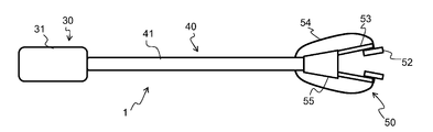
- FIG. 1A illustrates a top view of a fluid application device 1
- FIG. 1B is a side view of the device 1
- the device 1 includes a storage portion 30 including a reservoir 31 to store a liquid, an extended portion 40 including a shaft 41 , and a clamp portion 50 at an end of the extended shaft 41 .
- the clamp portion 50 includes sponges 52 to apply a fluid from the reservoir 31 to a plant or other surface.
- the device 1 may be used to apply an herbicide or other liquid to a plant, or it may be used to apply a cleaning liquid, paint, or any other liquid to a surface clasped between the sponges 52 .
- the device 1 includes a grip portion 10 including a handle 11 and trigger 12 .
- the reservoir 31 may rest on a support 32 , and may connect to the main body of the device 1 via a connector 33 .
- the reservoir 31 is illustrated as being on an opposite side of the handle 11 from the extended portion 40 , according to alternative embodiments, the reservoir may be located at any location, such as at a bottom portion of the handle 11 .
- the clamp portion 50 includes first and second arms 53 holding sponges 52 .
- Tubes 54 connect the reservoir 31 to the sponges 52 .
- the clamp portion 50 may also include a cover 55 and one or more hinge portions 56 to control the movement of the arms 53 towards and away from each other.
- the arms 53 When a user presses the trigger 12 , the arms 53 are moved together, and the sponges 52 may be pressed against each other. An object or plant to which a liquid is to be applied may be positioned between the sponges 52 . When the trigger 12 is pressed further, the fluid may be pumped from the reservoir 31 to the sponges 52 to apply the fluid to the object or plant.
- both the clamping and the fluid pumping operations are performed simultaneously when the trigger 12 is pressed in one direction.
- FIGS. 2A to 2D illustrate the structure and operation of the trigger portion 10 and the clamp portion 50 .
- the top portion of each figure corresponds to the trigger portion 10
- the lower portion of each figure illustrates a corresponding state of the clamp portion 50 .
- the trigger portion 10 includes the trigger 12 and handle 11 .
- the trigger 12 may rotate about a shaft 14 .
- a wire, cord, cable, or other connection line 15 may connect the trigger 12 to the arms 53 of the clamp portion 50 .
- the trigger 12 moves within a hole 13 in the body, represented by dashed lines in FIGS. 2A to 2D .
- a pump 16 is connected between the reservoir 31 and the trigger 12 .
- An actuator 18 extends from the pump 18 towards the trigger 12 , and tube 17 connects the reservoir 31 to the pump 16 .
- a tube 19 extends from the pump 16 to the tubes 54 a and 54 b that connect to the sponges 52 .
- FIG. 2A illustrates the trigger 12 in a resting state.
- the trigger 12 is located at a first distance, d 0 , from the handle 11 .
- FIG. 2A illustrates the position of the clamp portion 50 in the resting state.
- the clamp portion 50 includes two portions. Each portion may include a sponge 52 mounted onto a base plate 51 .
- FIG. 2A illustrates a first sponge 52 a mounted to a first base plate 51 a opposing a second sponge 52 b mounted to a second base plate 51 b .
- First and second tube connectors 54 a and 54 b supply fluid to the sponges 52 a and 52 b .
- First and second clamp arms 53 a and 53 b are connected to the first and second base plates 51 a and 51 b , and are designed to move toward and away from each other to cause the sponges 52 a and 52 b to contact each other and move away from each other.
- the sponges 52 a and 52 b and the base plates 51 a and 51 b are spaced apart from each other.
- the trigger 12 does not exert force upon the cable 15 , and consequently, the clamp arms 53 a and 53 b do not approach each other.
- the trigger 12 may constantly exert a force upon the cable 15 , but the force exerted in the resting state may be insufficient to cause the clamp arms 53 a and 53 b to approach each other.
- the trigger 12 does not press against the actuator 18 to cause the pump 16 to pump fluid from the reservoir 31 to the sponges 52 a and 52 b.
- FIG. 2B illustrates the trigger mechanism in a second state.
- the trigger 12 is pressed towards the handle 11 , as represented by the arrow A 1 .
- the trigger 12 pulls the cable 15 , as indicated by the arrow A 2 . Consequently, as shown in the lower portion of FIG. 2B , the clamp arms 53 a and 53 b are moved toward each other as indicated by the arrows A 3 and A 4 , and the sponges 52 a and 52 b are brought together to contact each other.
- the trigger 12 may contact the actuator 18 . However, the trigger 12 does not press the actuator toward the pump 16 , so that no fluid is pumped through the tube 19 to the sponges 52 a and 52 b . In other words, when the trigger 12 is squeezed a first distance, illustrated in FIG. 2B , the clamp arms 53 a and 53 b are moved towards each other, but the fluid is not pumped from the reservoir 31 to the clamp portion 50 .
- FIGS. 2C and 2D illustrate the trigger 12 pressed further toward the handle 11 to cause the pump 16 to pump fluid from the reservoir 31 to the sponges 52 a and 52 b .
- the trigger 12 is pressed toward the handle 11 as indicated by the arrow A 5 until the trigger 12 is located a distance d 2 from the handle 11 , where the distance d 2 is less than d 1 and d 0 .
- the trigger 12 presses the actuator 18 toward the pump 16 , activating the pump 16 , and pumping fluid from the reservoir 31 through the tube 19 as indicated by the arrow A 7 to the tubes 54 a and 54 b and the sponges 52 a and 52 b as indicated by the arrows A 10 and A 11 .
- the trigger 12 pulls the cable 15 as indicated by the arrow A 6 , so that the clamp arms 53 a and 53 b move toward each other, as indicated by the arrows A 8 and A 9 .
- the sponges 52 a and 52 b are pressed toward each other, which may compress the sponges 52 a and 52 b against each other.
- FIG. 2D illustrates a cable 15 having first and second portions 15 a and 15 b separated by a spring or elastic portion 21 and a stopper 20 .
- the trigger 12 is pulled up to the first position illustrated in FIG. 2B , the cable 15 is also pulled with the trigger 12 .
- the first portion of the cable 15 a is stopped by the stopper 20 so that the sponges 52 a and 52 b are not compressed together, and the second portion of the cable 15 b moves with the trigger 12 . Consequently, when the cable 15 includes an elastic portion or spring portion, the fluid may be pumped to the clamp portions 50 without further pressing the sponges 52 a and 52 b against each other.
- the spring or elastic member 21 may be positioned so that the sponges 52 a and 52 b compress against each other to a predetermined degree.
- FIG. 2D illustrates a configuration in which the sponges 52 a and 52 b do not compress each other
- the cable 15 may be configured to allow any predetermined degree of compression.
- the cable may be designed to have a predetermined degree of elasticity instead of having a separate elastic member or spring 21 .
- FIGS. 2A to 2D illustrate one configuration of a trigger 12 , pump 16 , and cable 15
- the cable may be a rigid rod, a rope, or a metal cable.
- the pump 16 may be on an opposing side of the trigger 12 , the pump 16 may be controlled by a pulling motion, a pressure-generating function, or by any other pumping function, and the trigger 12 may have any configuration including a rotation about the top as illustrated in FIGS. 2A to 2D , rotation about a bottom, or a linear sliding motion.
- FIGS. 3A to 3F illustrate different types of trigger mechanisms.
- the trigger 12 rotates about a shaft in a top portion of the trigger 12 .
- the trigger slides linearly toward the handle 11 .
- the trigger 12 may not have a rotation motion when pressed toward the handle 11 .
- FIGS. 3E and 3F illustrate a trigger that rotates about a shaft or hinge in a bottom portion of the trigger 12 .
- FIGS. 4A and 4B illustrate the sponge and base plate of the clamp portion 50 .
- the sponge 52 is mounted to the base plate 51 which provides a stiff rear surface to allow the sponge 52 to compress against another sponge 52 .
- only one of the clamp arms may include a sponge 52 , and the other may be a rigid surface against which the sponge 52 may press.
- the base plate 51 may include a nozzle 59 to provide liquid to the sponges 52 .
- the sponge 52 may include an opening 58 .
- the opening 58 may provide a path for the fluid to enter the sponge 52 .
- the inner surface of the opening 58 may also provide a surface area into which the fluid may penetrate to saturate the entire sponge 52 .
- the nozzle 59 may supply the fluid directly into the sponge 52 , and there may be no opening in the sponge 52 .
- the base plate 51 may also be provided with grooves or ridges to provide a capillary action for the fluid to disperse to the entire sponge 52 .
- FIGS. 1A to 4B illustrate a substantially rectangular sponge located on an inside surface of the base plate.
- the sponge may be of any desired shape, and may also be located on different surfaces of the base plate.
- the base plate may have different shapes.
- FIGS. 5A to 5C illustrate side views of the clamp portion 50 , including the clamp arm 53 and the base plate 51 .
- sponges 57 are included on a bottom side of the base plate 51 , where the bottom side is the side that faces the ground.
- the clamp arm 53 may be arranged at any angle, as illustrated in the figures.
- the clamp arm 53 may be arranged between 30 degrees to 60 degrees with respect to a horizontal plane defined by the ground and parallel to a bottom surface of the base plate 51 .
- a user may hold the handle 11 and the bottom surface of the base plate may be aligned with the horizontal plane to allow the user to apply the sponge 57 to the ground.
- FIGS. 5A to 5C also illustrate the fluid receiving hole or tube 54 to receive fluid from the reservoir 31 and to provide the fluid to the sponges 52 .
- FIG. 5C illustrates a base plate 51 having a rounded shape, and the sponge 57 located on the outer surface of the base plate 51 . Consequently, the clamp arm 53 may be held at any angle to correspond to users of different heights or ground levels of varying elevations, and the sponge 57 may still be parallel to or tangential to the ground to allow the user to apply the sponge 57 to the ground.
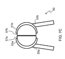
- FIGS. 6A to 6D illustrate front views of the clamp portion 50 .
- sponges 57 a and 57 b are positioned below each of the sponges 52 a and 52 b and the base plates 51 a and 51 b .
- the fluid tubes 54 a and 54 b may supply fluid to the sponges 52 a and 52 b , and the fluid may drain to the sponges 57 a and 57 b .
- the fluid tubes 54 a and 54 b may include a second set of tubes that supply fluid directly to the sponges 57 a and 57 b.
- the sponges 52 and 57 are illustrated as separate sponges. However, the sponges 52 and 57 may be a single sponge that is bent to cover the inside surface and bottom surface of the respective base plate 51 .
- FIG. 6B illustrates a clamp portion 50 in which the sponges 57 a and 57 b are located along the front sides of the base plates 51 a and 51 b
- the device of FIG. 6B may correspond to the device of FIG. 5C , in which the sponges 57 a and 57 b surround the bottom and front sides of the base plate 51 .
- FIG. 6C illustrates an embodiment in which the inside sponges 52 a and 52 b extend past a bottom ends of the base plates 51 a and 51 b by a distance d 3 to allow the sponges 52 a and 52 b to contact a surface below the bottom side or surface of the base plates 52 a and 52 b .
- No sponge may be located directly beneath the bottom surfaces of the base plates 51 a and 51 b .
- the clamp portion 50 of FIG. 6C may correspond to the clamp portions 50 of FIGS. 5A and 5B , for example.
- FIG. 6D illustrates a front view of a clamp portion 50 having base plates 51 a and 51 b which each have bottom surfaces extending from the main portion of the base plates 52 a and 52 b .
- the bottom surfaces may be of rectangular shapes, semi-circular shapes, or any other desired shape, as viewed from the bottom, and they provide a larger surface area for contacting a surface beneath the clamp portion 50 .
- the sponges 57 a and 57 b provide the user with a larger surface area for contacting the plant.
- the features of FIG. 6D may be combined with those of FIGS. 5C to provide a sponge 57 that extends around the outer sides of the base plate 51 while also extending outward from the base plate 51 .
- FIGS. 7A to 7C illustrate the clamp portion 50 from the bottom side view.
- FIG. 7A illustrates a clamp portion 50 in which sponges 52 a and 52 b are located on inside surfaces of the base plates 51 a and 51 b , respectively, but no sponge is located on the bottom surfaces of the base plates 51 a and 51 b .
- the clamp portion 50 of FIG. 7A may correspond to the clamp portion 50 of FIG. 6C , for example.
- FIG. 7B illustrates a bottom side view of a clamp portion in which the sponges 57 a and 57 b extend across the bottom surface of the base plates 51 a and 51 b .
- sponges 57 a and 57 b cover the bottom surface of the base plates 51 a and 51 b .
- each base plate 51 a and 51 b may include only a single sponge 52 a and 52 b , respectively, that is bent to cover both the inside surface of the base plate 51 and the bottom surface of the base plate 51 .
- FIG. 7C illustrates the clamp portion 50 in which the base plates 51 a and 51 b include extended portions at the bottom.
- the extended portions are covered in part by sponges 57 a and 57 b to provide a larger surface area to apply a fluid in the sponges 57 a and 57 b to a surface adjacent to the bottom surface of the base plates 51 a and 51 b .
- the clamp portion 50 of FIG. 7C may correspond to the clamp portion 50 of FIG. 6D , for example.
Abstract
A fluid application device includes a clamp portion including two clamp arms, at least one of the clamp arms including a sponge, a reservoir to store a fluid, and a trigger to move the clamp arms towards each other when pressed a first distance and to pump fluid from the reservoir to the sponge when pressed a second distance greater than the first distance.
Description
The present application claims the benefit of Provisional Application No. 61/392,965, filed Oct. 14, 2010.
Plant and weed killing apparatuses are widely used in gardens, lawns, and plant beds both professionally and in by private gardeners. A common method of killing plants and weeds includes spraying herbicide onto the plant or weeds. However, this method can result in wasted herbicide, killing adjacent plants, and harming other plants and ecosystems when the herbicide runs off into the water supply.
Other plant and weed killing apparatuses allow a gardener to apply herbicide directly to a plant or weed using a porous surface, such as a sponge. However, in a crowded garden, herbicide may still contact adjacent plants.
Disclosed are a system and apparatus to apply a fluid to an object without applying the fluid to adjacent objects. In particular, disclosed is a fluid application device having a trigger that performs the functions of clamping a clamp and applying a fluid to sponges attached to the clamp.
Features of the present invention may be realized by a fluid application device including a clamp portion including two clamp arms, at least one of the clamp arms including a sponge, a reservoir to store a fluid, and a trigger to move the clamp arms towards each other and to pump fluid from the reservoir, both while pressing the trigger in the same direction. The clamp arms may move toward each other when the trigger is pressed a first distance and the fluid may be pumped from the reservoir to the sponge when pressed a second distance greater than the first distance.
The fluid application device may include a cable connected between the trigger and the clamp arms to move the clamp arms towards each other when the trigger is pressed.
The cable may include an elastic portion, such that the clamp arms move toward each other when the trigger is pressed the first distance, and the elastic portion prevents the clamp arms from moving toward each other when the trigger is pressed the second distance.
Each of the clamp arms may include a sponge, and the sponges may contact each other when the trigger is pressed the first distance.
The fluid application device may further include first and second tubes to supply fluid to the respective sponges of the clamp arms, and a third tube to supply fluid from the reservoir to the first and second tubes.
The fluid application device may further include a pump to pump fluid from the reservoir to the third tube, and wherein the trigger may activate the pump when pressed the second distance.
The trigger may not activate the pump when pressed the first distance.
Each sponge may be mounted to a base plate, and each base plate may be mounted to a respective clamp arm.
Each sponge may include a first portion to cover an inside surface of a respective base plate facing an opposing base plate, and a second portion to cover a side surface of the base plate.
The side surface of the base plate may include a bottom surface of the base plate.
The side surface of the base plate may further include at least a portion of a front surface of the base plate.
Each sponge may be mounted to an inside surface of a respective base plate facing an opposing base plate, and each sponge may extend past a bottom edge of the respective base plate.
Each sponge may not cover a side surface of the respective base plate other than the inside surface of the respective base plate.
Each base plate may include a nozzle to supply the fluid to the sponges, and each sponge may include an opening surrounding the nozzle.
Features of the present invention may also be realized by a fluid application device, including a clamp portion including two clamp arms, each clamp arm having a base plate mounted thereon, at least one of the base plates having a sponge mounted thereon to face the other base plate, a fluid storing reservoir, and a trigger to move the clamp arms towards each other without providing fluid to the sponge when moved from a rest position toward a first position, and to provide fluid to the sponge when moved to a second position past the first position with respect to the rest position.
The trigger may not move the clamp arms towards each other when moving from the first position to the second position.
Features of the present invention may also be realized by a method of supplying fluid in a fluid supplying device including two clamping arms, at least one of the clamping arms having a sponge mounted thereon, and a trigger to move the clamp arms and to supply a fluid to the sponge, the method including moving a trigger from a rest position to a first position, in response to moving the trigger from the rest position to the first position, moving the clamp arms toward each other, moving the trigger from the first position to a second position, the second position being farther from the rest position than the first position, and in response to moving the trigger from the first position to the second position, supplying fluid to the sponge.
The clamp arms may not be moved toward each other when the trigger is moved from the first position to the second position.
The fluid may not be supplied to the sponge when the trigger is moved from the rest position to the first position.
The device 1 includes a grip portion 10 including a handle 11 and trigger 12. The reservoir 31 may rest on a support 32, and may connect to the main body of the device 1 via a connector 33.
Although the reservoir 31 is illustrated as being on an opposite side of the handle 11 from the extended portion 40, according to alternative embodiments, the reservoir may be located at any location, such as at a bottom portion of the handle 11.
The clamp portion 50 includes first and second arms 53 holding sponges 52. Tubes 54 connect the reservoir 31 to the sponges 52. The clamp portion 50 may also include a cover 55 and one or more hinge portions 56 to control the movement of the arms 53 towards and away from each other.
When a user presses the trigger 12, the arms 53 are moved together, and the sponges 52 may be pressed against each other. An object or plant to which a liquid is to be applied may be positioned between the sponges 52. When the trigger 12 is pressed further, the fluid may be pumped from the reservoir 31 to the sponges 52 to apply the fluid to the object or plant.
According to an alternative embodiment, both the clamping and the fluid pumping operations are performed simultaneously when the trigger 12 is pressed in one direction.
The trigger portion 10 includes the trigger 12 and handle 11. The trigger 12 may rotate about a shaft 14. A wire, cord, cable, or other connection line 15 may connect the trigger 12 to the arms 53 of the clamp portion 50. The trigger 12 moves within a hole 13 in the body, represented by dashed lines in FIGS. 2A to 2D . A pump 16 is connected between the reservoir 31 and the trigger 12. An actuator 18 extends from the pump 18 towards the trigger 12, and tube 17 connects the reservoir 31 to the pump 16. A tube 19 extends from the pump 16 to the tubes 54 a and 54 b that connect to the sponges 52.
The lower portion of FIG. 2A illustrates the position of the clamp portion 50 in the resting state. The clamp portion 50 includes two portions. Each portion may include a sponge 52 mounted onto a base plate 51. For example, FIG. 2A illustrates a first sponge 52 a mounted to a first base plate 51 a opposing a second sponge 52 b mounted to a second base plate 51 b. First and second tube connectors 54 a and 54 b supply fluid to the sponges 52 a and 52 b. First and second clamp arms 53 a and 53 b are connected to the first and second base plates 51 a and 51 b, and are designed to move toward and away from each other to cause the sponges 52 a and 52 b to contact each other and move away from each other.
In the resting position, the sponges 52 a and 52 b and the base plates 51 a and 51 b are spaced apart from each other. The trigger 12 does not exert force upon the cable 15, and consequently, the clamp arms 53 a and 53 b do not approach each other. Alternatively, the trigger 12 may constantly exert a force upon the cable 15, but the force exerted in the resting state may be insufficient to cause the clamp arms 53 a and 53 b to approach each other. In addition, the trigger 12 does not press against the actuator 18 to cause the pump 16 to pump fluid from the reservoir 31 to the sponges 52 a and 52 b.
In the second state illustrated in FIG. 2B , the trigger 12 may contact the actuator 18. However, the trigger 12 does not press the actuator toward the pump 16, so that no fluid is pumped through the tube 19 to the sponges 52 a and 52 b. In other words, when the trigger 12 is squeezed a first distance, illustrated in FIG. 2B , the clamp arms 53 a and 53 b are moved towards each other, but the fluid is not pumped from the reservoir 31 to the clamp portion 50.
In FIG. 2C , the trigger 12 pulls the cable 15 as indicated by the arrow A6, so that the clamp arms 53 a and 53 b move toward each other, as indicated by the arrows A8 and A9. The sponges 52 a and 52 b are pressed toward each other, which may compress the sponges 52 a and 52 b against each other.
In addition, the spring or elastic member 21 may be positioned so that the sponges 52 a and 52 b compress against each other to a predetermined degree. In other words, although FIG. 2D illustrates a configuration in which the sponges 52 a and 52 b do not compress each other, the cable 15 may be configured to allow any predetermined degree of compression. Alternatively, the cable may be designed to have a predetermined degree of elasticity instead of having a separate elastic member or spring 21.
Although FIGS. 2A to 2D illustrate one configuration of a trigger 12, pump 16, and cable 15, any configuration may be used to achieve a similar result. For example, the cable may be a rigid rod, a rope, or a metal cable. Likewise, the pump 16 may be on an opposing side of the trigger 12, the pump 16 may be controlled by a pulling motion, a pressure-generating function, or by any other pumping function, and the trigger 12 may have any configuration including a rotation about the top as illustrated in FIGS. 2A to 2D , rotation about a bottom, or a linear sliding motion.
The base plate 51 may include a nozzle 59 to provide liquid to the sponges 52. The sponge 52 may include an opening 58. The opening 58 may provide a path for the fluid to enter the sponge 52. The inner surface of the opening 58 may also provide a surface area into which the fluid may penetrate to saturate the entire sponge 52. Alternatively, as illustrated in FIG. 4B , the nozzle 59 may supply the fluid directly into the sponge 52, and there may be no opening in the sponge 52. The base plate 51 may also be provided with grooves or ridges to provide a capillary action for the fluid to disperse to the entire sponge 52.
In FIG. 6A , the sponges 52 and 57 are illustrated as separate sponges. However, the sponges 52 and 57 may be a single sponge that is bent to cover the inside surface and bottom surface of the respective base plate 51.
Although a few examples have been shown and described, it would be appreciated by those skilled in the art that changes may be made in these examples without departing from the principles and spirit of the general inventive concept.
Claims (17)
1. A fluid application device, including:
a clamp portion including two clamp arms, at least one of the clamp arms including a sponge;
a reservoir to store a fluid;
a trigger to move the clamp arms towards each other when pressed a first distance and to pump fluid from the reservoir to the sponge when pressed a second distance greater than the first distance; and
a cable connected between the trigger and the clamp arms to move the clamp arms towards each other when the trigger is pressed.
2. The fluid application device of claim 1 , wherein the cable includes an elastic portion, such that the clamp arms move toward each other when the trigger is pressed the first distance, and the elastic portion prevents the clamp arms from moving toward each other when the trigger is pressed the second distance.
3. The fluid application device of claim 1 , wherein each of the clamp arms includes a sponge, and the sponges contact each other when the trigger is pressed the first distance.
4. The fluid application device of claim 3 , further comprising first and second tubes to supply fluid to the respective sponges of the clamp arms, and a third tube to supply fluid from the reservoir to the first and second tubes.
5. The fluid application device of claim 4 , further comprising a pump to pump fluid from the reservoir to the third tube,
wherein the trigger activates the pump when pressed the second distance.
6. The fluid application device of claim 5 , wherein the trigger does not activate the pump when pressed the first distance.
7. The fluid application device of claim 3 , wherein each sponge is mounted to a base plate, and
each base plate is mounted to a respective clamp arm.
8. The fluid application device of claim 7 , wherein each sponge includes a first portion to cover an inside surface of a respective base plate facing an opposing base plate, and a second portion to cover a side surface of the base plate.
9. The fluid application device of claim 8 , wherein the side surface of the base plate includes a bottom surface of the base plate.
10. The fluid application device of claim 9 , wherein the side surface of the base plate further includes at least a portion of a front surface of the base plate.
11. The fluid application device of claim 7 , wherein each sponge is mounted to an inside surface of a respective base plate facing an opposing base plate, and
each sponge extends past a bottom edge of the respective base plate.
12. The fluid application device of claim 11 , wherein each sponge does not cover a side surface of the respective base plate other than the inside surface of the respective base plate.
13. The fluid application device of claim 7 , wherein each base plate includes a nozzle to supply the fluid to the sponges, and
each sponge includes an opening surrounding the nozzle.
14. A fluid application device, comprising:
a clamp portion including two clamp arms, each clamp arm having a base plate mounted thereon, at least one of the base plates having a sponge mounted thereon to face the other base plate;
a fluid storing reservoir; and
a trigger to move the clamp arms towards each other without providing fluid to the sponge when moved from a rest position toward a first position, and to provide fluid to the sponge when moved to a second position past the first position with respect to the rest position,
wherein the trigger does not move the clamp arms towards each other when moving from the first position to the second position.
15. A method of supplying fluid in a fluid supplying device including two clamping arms, at least one of the clamping arms having a sponge mounted thereon, and a trigger to move the clamp arms and to supply a fluid to the sponge, the method comprising:
moving a trigger from a rest position to a first position;
in response to moving the trigger from the rest position to the first position, moving the clamp arms toward each other;
moving the trigger from the first position to a second position, the second position being farther from the rest position than the first position; and
in response to moving the trigger from the first position to the second position, supplying fluid to the sponge,
wherein the clamp arms are not moved toward each other when the trigger is moved from the first position to the second position.
16. The method of claim 15 , wherein fluid is not supplied to the sponge when the trigger is moved from the rest position to the first position.
17. A fluid application device, including:
a clamp portion including two clamp arms, each of the clamp arms includes a sponge;
a reservoir to store a fluid;
a trigger configured to move the clamp arms towards each other when pressed a first distance, the sponges configured to contract each other when the trigger is pressed the first distance, and the trigger configured to pump fluid from the reservoir to the sponge when pressed a second distance greater than the first distance; and
first and second tubes configured to supply fluid to the respective sponges of the clamp arms, and a third tube configured to supply fluid from the reservoir to the first and second tubes.
Priority Applications (2)
| Application Number | Priority Date | Filing Date | Title |
|---|---|---|---|
| US13/251,247 US8944709B2 (en) | 2010-10-14 | 2011-12-15 | Fluid application device |
| US14/596,294 US20150122834A1 (en) | 2010-10-14 | 2015-01-14 | Fluid Application Device and Method |
Applications Claiming Priority (2)
| Application Number | Priority Date | Filing Date | Title |
|---|---|---|---|
| US39296510P | 2010-10-14 | 2010-10-14 | |
| US13/251,247 US8944709B2 (en) | 2010-10-14 | 2011-12-15 | Fluid application device |
Related Child Applications (1)
| Application Number | Title | Priority Date | Filing Date |
|---|---|---|---|
| US14/596,294 Continuation US20150122834A1 (en) | 2010-10-14 | 2015-01-14 | Fluid Application Device and Method |
Publications (2)
| Publication Number | Publication Date |
|---|---|
| US20120093568A1 US20120093568A1 (en) | 2012-04-19 |
| US8944709B2 true US8944709B2 (en) | 2015-02-03 |
Family
ID=45934283
Family Applications (2)
| Application Number | Title | Priority Date | Filing Date |
|---|---|---|---|
| US13/251,247 Expired - Fee Related US8944709B2 (en) | 2010-10-14 | 2011-12-15 | Fluid application device |
| US14/596,294 Abandoned US20150122834A1 (en) | 2010-10-14 | 2015-01-14 | Fluid Application Device and Method |
Family Applications After (1)
| Application Number | Title | Priority Date | Filing Date |
|---|---|---|---|
| US14/596,294 Abandoned US20150122834A1 (en) | 2010-10-14 | 2015-01-14 | Fluid Application Device and Method |
Country Status (1)
| Country | Link |
|---|---|
| US (2) | US8944709B2 (en) |
Cited By (6)
| Publication number | Priority date | Publication date | Assignee | Title |
|---|---|---|---|---|
| US9409003B2 (en) | 2012-12-07 | 2016-08-09 | Cook Medical Technologies, LLC | System for reducing local discomfort |
| US20170027154A1 (en) * | 2015-07-30 | 2017-02-02 | James E. Waller | Hand-held clamping herbicide applicator |
| US10561137B1 (en) | 2016-09-06 | 2020-02-18 | Dennis R. Dullinger | Weed-e-bug |
| USD908489S1 (en) | 2019-08-02 | 2021-01-26 | Ross Lazarov | Herbicide sprayer low pressure foam tip |
| US11000658B2 (en) | 2014-05-18 | 2021-05-11 | Awair, Inc. | Device to reduce discomfort in the upper airway |
| US11207708B2 (en) | 2018-12-21 | 2021-12-28 | Chapin Manufacturing, Inc. | Handheld fluid applicator |
Families Citing this family (2)
| Publication number | Priority date | Publication date | Assignee | Title |
|---|---|---|---|---|
| BE1021614B1 (en) * | 2013-01-17 | 2015-12-18 | TEUGELS, Peter Wilfried M. | DEVICE FOR WEED SPREADING |
| CA3199696A1 (en) * | 2020-11-01 | 2022-05-05 | Darrell Lee Fuller | Fluid application device |
Citations (10)
| Publication number | Priority date | Publication date | Assignee | Title |
|---|---|---|---|---|
| US2338195A (en) * | 1942-04-16 | 1944-01-04 | Ibm | Stencil moistening machine |
| US3048878A (en) * | 1959-07-15 | 1962-08-14 | Kleer Site Corp | Eyeglass liquid applicator device |
| US4347010A (en) * | 1979-08-13 | 1982-08-31 | Alex Petkoff | Cleaning device for eyeglasses |
| US4716677A (en) | 1986-03-26 | 1988-01-05 | Moore James E | Manual devices and methods for selective application of chemical substances to plants |
| US4947580A (en) * | 1986-03-26 | 1990-08-14 | Moore James E | Manual devices and methods for selective application of chemical substances to plants |
| US5222268A (en) * | 1992-01-24 | 1993-06-29 | Snodgrass George F | Pocket eyeglass cleaner apparatus |
| US5329727A (en) | 1993-08-10 | 1994-07-19 | Dixon Madison F | Topical herbal treatment applicator |
| US5499474A (en) | 1994-11-28 | 1996-03-19 | Knooihuizen; Louis D. | Method and apparatus for liquid application |
| US5724765A (en) | 1996-01-22 | 1998-03-10 | Wegner; Walter A. | Herbicide applicator with vegetation grabbing jaws |
| US6558060B1 (en) * | 2002-01-11 | 2003-05-06 | Seshadri Raju | Catheter guidewire lubricating device |
Family Cites Families (1)
| Publication number | Priority date | Publication date | Assignee | Title |
|---|---|---|---|---|
| CA2633071A1 (en) * | 2005-12-14 | 2007-06-21 | Rad Omid | Chemical applicator |
-
2011
- 2011-12-15 US US13/251,247 patent/US8944709B2/en not_active Expired - Fee Related
-
2015
- 2015-01-14 US US14/596,294 patent/US20150122834A1/en not_active Abandoned
Patent Citations (10)
| Publication number | Priority date | Publication date | Assignee | Title |
|---|---|---|---|---|
| US2338195A (en) * | 1942-04-16 | 1944-01-04 | Ibm | Stencil moistening machine |
| US3048878A (en) * | 1959-07-15 | 1962-08-14 | Kleer Site Corp | Eyeglass liquid applicator device |
| US4347010A (en) * | 1979-08-13 | 1982-08-31 | Alex Petkoff | Cleaning device for eyeglasses |
| US4716677A (en) | 1986-03-26 | 1988-01-05 | Moore James E | Manual devices and methods for selective application of chemical substances to plants |
| US4947580A (en) * | 1986-03-26 | 1990-08-14 | Moore James E | Manual devices and methods for selective application of chemical substances to plants |
| US5222268A (en) * | 1992-01-24 | 1993-06-29 | Snodgrass George F | Pocket eyeglass cleaner apparatus |
| US5329727A (en) | 1993-08-10 | 1994-07-19 | Dixon Madison F | Topical herbal treatment applicator |
| US5499474A (en) | 1994-11-28 | 1996-03-19 | Knooihuizen; Louis D. | Method and apparatus for liquid application |
| US5724765A (en) | 1996-01-22 | 1998-03-10 | Wegner; Walter A. | Herbicide applicator with vegetation grabbing jaws |
| US6558060B1 (en) * | 2002-01-11 | 2003-05-06 | Seshadri Raju | Catheter guidewire lubricating device |
Cited By (10)
| Publication number | Priority date | Publication date | Assignee | Title |
|---|---|---|---|---|
| US9409003B2 (en) | 2012-12-07 | 2016-08-09 | Cook Medical Technologies, LLC | System for reducing local discomfort |
| US9744340B2 (en) | 2012-12-07 | 2017-08-29 | Cook Medical Technologies Llc | System for reducing local discomfort |
| US10363403B2 (en) | 2012-12-07 | 2019-07-30 | Cook Medical Technologies Llc | System for reducing local discomfort |
| US11690987B2 (en) | 2012-12-07 | 2023-07-04 | Awair, Inc. | System for reducing local discomfort |
| US11000658B2 (en) | 2014-05-18 | 2021-05-11 | Awair, Inc. | Device to reduce discomfort in the upper airway |
| US20170027154A1 (en) * | 2015-07-30 | 2017-02-02 | James E. Waller | Hand-held clamping herbicide applicator |
| US10561137B1 (en) | 2016-09-06 | 2020-02-18 | Dennis R. Dullinger | Weed-e-bug |
| US11517009B1 (en) * | 2016-09-06 | 2022-12-06 | Lori J. Sommerfield | Weed-E-Bug |
| US11207708B2 (en) | 2018-12-21 | 2021-12-28 | Chapin Manufacturing, Inc. | Handheld fluid applicator |
| USD908489S1 (en) | 2019-08-02 | 2021-01-26 | Ross Lazarov | Herbicide sprayer low pressure foam tip |
Also Published As
| Publication number | Publication date |
|---|---|
| US20120093568A1 (en) | 2012-04-19 |
| US20150122834A1 (en) | 2015-05-07 |
Similar Documents
| Publication | Publication Date | Title |
|---|---|---|
| US8944709B2 (en) | Fluid application device | |
| US7040510B1 (en) | Extension arm for trigger pump spray containers | |
| US20120227763A1 (en) | Floor mop | |
| AU2011276963B2 (en) | Applicator device | |
| US5775595A (en) | Gravity fed sprayer | |
| US20090256033A1 (en) | Brush holder | |
| CN203897106U (en) | All-dimensional pesticide spraying device | |
| CN204260686U (en) | Mopping device | |
| KR200493688Y1 (en) | spray apparatus with easy shoot even at little remains of contents | |
| WO2004087333A3 (en) | Liquid application system | |
| EP3282838B1 (en) | Handheld device | |
| KR200484036Y1 (en) | A multi-purpose liquid sprayer | |
| US6088867A (en) | Combined mop and brush assembly | |
| KR200487258Y1 (en) | Holder Bar For Crop Duster | |
| US20110079617A1 (en) | Actuation device for a spray can | |
| US8083155B2 (en) | Rolling herbicide applicator with an adjustable shield | |
| CN205196805U (en) | Pesticide spraying device | |
| US7418758B1 (en) | Baseboard cleaning apparatus | |
| CN203872873U (en) | Applicator special for sterilant herbicides | |
| KR101381011B1 (en) | Compression device of sprayer | |
| US20070113864A1 (en) | Disposable manicure and nail cleaning device | |
| USD502759S1 (en) | Herbicide applicator | |
| JP3513628B2 (en) | Spraying device for chemicals on tea plant | |
| KR200495968Y1 (en) | Spray apparatus for easy spraying of the remaining amount | |
| JP2015177923A (en) | Spray for cosmetic |
Legal Events
| Date | Code | Title | Description |
|---|---|---|---|
| FEPP | Fee payment procedure |
Free format text: MAINTENANCE FEE REMINDER MAILED (ORIGINAL EVENT CODE: REM.); ENTITY STATUS OF PATENT OWNER: SMALL ENTITY |
|
| LAPS | Lapse for failure to pay maintenance fees |
Free format text: PATENT EXPIRED FOR FAILURE TO PAY MAINTENANCE FEES (ORIGINAL EVENT CODE: EXP.); ENTITY STATUS OF PATENT OWNER: SMALL ENTITY |
|
| STCH | Information on status: patent discontinuation |
Free format text: PATENT EXPIRED DUE TO NONPAYMENT OF MAINTENANCE FEES UNDER 37 CFR 1.362 |
|
| FP | Expired due to failure to pay maintenance fee |
Effective date: 20190203 |