US8942775B2 - Handheld apparatus and method for the automated application of cosmetics and other substances - Google Patents
Handheld apparatus and method for the automated application of cosmetics and other substances Download PDFInfo
- Publication number
- US8942775B2 US8942775B2 US13/019,462 US201113019462A US8942775B2 US 8942775 B2 US8942775 B2 US 8942775B2 US 201113019462 A US201113019462 A US 201113019462A US 8942775 B2 US8942775 B2 US 8942775B2
- Authority
- US
- United States
- Prior art keywords
- skin
- applicator
- area
- light sources
- handheld device
- Prior art date
- Legal status (The legal status is an assumption and is not a legal conclusion. Google has not performed a legal analysis and makes no representation as to the accuracy of the status listed.)
- Expired - Fee Related, expires
Links
Images


Classifications
-
- A—HUMAN NECESSITIES
- A45—HAND OR TRAVELLING ARTICLES
- A45D—HAIRDRESSING OR SHAVING EQUIPMENT; EQUIPMENT FOR COSMETICS OR COSMETIC TREATMENTS, e.g. FOR MANICURING OR PEDICURING
- A45D44/00—Other cosmetic or toiletry articles, e.g. for hairdressers' rooms
- A45D44/005—Other cosmetic or toiletry articles, e.g. for hairdressers' rooms for selecting or displaying personal cosmetic colours or hairstyle
-
- A—HUMAN NECESSITIES
- A45—HAND OR TRAVELLING ARTICLES
- A45D—HAIRDRESSING OR SHAVING EQUIPMENT; EQUIPMENT FOR COSMETICS OR COSMETIC TREATMENTS, e.g. FOR MANICURING OR PEDICURING
- A45D34/00—Containers or accessories specially adapted for handling liquid toiletry or cosmetic substances, e.g. perfumes
- A45D34/04—Appliances specially adapted for applying liquid, e.g. using roller or ball
- A45D34/041—Appliances specially adapted for applying liquid, e.g. using roller or ball using a roller, a disc or a ball
Definitions
- the current invention relates to automated computer-controlled methods to identify skin texture and to selectively and precisely apply one or more reflectance modifying agent, such as a dye or pigment, to human skin to improve its visual attractiveness.
- one or more reflectance modifying agent such as a dye or pigment
- Prior art techniques for modifying the appearance of skin include natural tanning, artificial tanning, and the deliberate application of cosmetics. Each of these prior art techniques has limitations.
- the applications of cosmetic substances to skin are largely manual, for example through the use of brushes, application tubes, pencils, pads, and fingers.
- the application methods make prior art cosmetics imprecise, labor intensive, expensive, and sometimes harmful, when compared to the computerized techniques of the present invention.
- RMA reflectance modifying agent
- Some examples of RMA are inks, dyes, pigments, bleaching agents, chemically altering agents, and other substances that can alter the reflectance of human skin and other features.
- the terms “dye” and “transparent dyes” are used for brevity in this specification to represent any RMA.
- Manual cosmetic applications are imprecise compared to computer-controlled techniques, and this imprecision may make them less effective.
- the heavy application of a foundation base for makeup may cause an unattractive, caked-on appearance.
- Manual techniques also typically take a long time to employ, as can be seen in any morning commute on a highway, where people concentrically take advantage of stops to finish applying their makeup.
- manually applied makeup is not cheap, and when the help of professionals such as beauticians is required, is even more expensive.
- materials applied to the skin in manual techniques are themselves potentially harmful.
- a foundation base for makeup may cause skin to dry out and may inhibit the skin's breathing. Sunlight or artificial light used for tanning may cause cancer.
- a useful applicator would be small enough to be held in the hand, would be easy to clean, and would be inexpensive to produce.
- it would maintain the scanner and RMA application system at an appropriate distance from the surface to be treated, to ensure accurate scanning and deposition. If the scanner is located too far from or too close to the surface, for example, the results of scanning may not be not be accurate enough to provide a basis for pixel-level cosmetic enhancements. In the same way, a printer head that is not maintained at a proper distance from the surface, for example, will not be able to apply the RMAs with pixel-level precision.
- An additional challenge in designing an automated RMA system is preventing outside light from entering around the base of the applicator and scanner and distorting the accuracy of the scanning.
- the design of the applicator must limit smudging of the RMAs on the surface treated, which may result from contact with hardware elements of the scanner or inkjet printer head. If the rim of an inkjet printer head used for applying RMAs drags across the skin during deposition, for example, it may smudge the effect of the RMAs on the skin. This is especially a problem when applications involve making multiple passes over the surface, because the freshly deposited RMAs may be easily smudged by too much contact with hard surfaces.
- an RMA applicator head designed so that the applicator is small enough to be handheld, easy to clean, and inexpensive, and that maintains a proper distance between the scanner and RMA printer head and the surface to be treated, while reducing the influence of outside light during scanning and limiting smudging during deposition.
- An important element of a cosmetic enhancement system is the ability to separate a scanned image of an area of skin or other human feature into two components, color and surface texture.
- Color refers to an area's light value, such as lightness and darkness, as well as hue, such as pinkness or yellowness.
- Surface texture refers to the area's topography, such as the contours of pores, wrinkles, and bumps, both large and small.
- the system's software uses strategies to accentuate, alter, or camouflage color effects and different strategies for surface texture effects, to make a woman look both young and real.
- a computer-controlled system determines attributes of a frexel, an area of human skin, and applies a reflectance modifying agent (RMA) at the pixel level, to make the skin appear more attractive.
- the system's scanner and RMA applicator are moved across the skin by means of elements with dispersed raised contact points, for example pounce wheels, which are wheels with points around their outer rims. These contact points maintain a proper distance from the surface to be treated, reduce the influence of outside light during scanning, and limit smudging during deposition.
- Different motion means with dispersed raise contact points may also used, such as a ball, a comb-like walker, or other geometrical shapes. For example, a square configuration of motion means may be used or a circular one.
- the applicator head further comprises a thin inkjet printer head, a telecentric field lens, a camera, and an RMA reservoir and is attached via a power and data cable to a computer.
- software on the computer uses a camera to sense aspects of color and texture on human features, calculates cosmetic enhancements, and uses the printer head to apply RMA precisely to the features to create those enhancements. Skin landmarks are used for registration.
- a software method of differential lighting automatically determines aspects of surface texture from scanned data about an area of skin or other human feature, using a computerized system for scanning that area, calculating enhancements, and applying cosmetics.
- Scanning with varying configurations of applied lighting captures images in a cycle, with the lighting for some exposures left dark.
- the exposures are co-synchronized in stacks, where each stack is a grouping of data about a particular instant of time during the scanning. This data may be obtained from directly captured exposures or from interpolated data.
- Data from an exposure made without applied lighting is subtracted from each stack to remove edge leakage from ambient light.
- the remaining exposures are used to generate the albedo (color), the north-south tilt, and the east-west tilt of the scanned area.
- the exposures are then stacked in their visual position in computer memory, and the data is updated using a noise filtering average.
- FIG. 1 is a block diagram that illustrates the relative size an RMA applicator head
- FIG. 2 is a block diagram that illustrates elements of an RMA applicator head
- FIG. 3 is a flow chart illustrating the general steps for a process of applying RMA with the applicator head
- FIG. 4 is a representative diagram illustrating a path of movement of the applicator head over an area of skin whereby multiple overlapping images may be captured;
- FIG. 5 is a representative diagram illustrating aspects associated with the present invention that require registration
- FIG. 6A is a representational diagram illustrating a side view of a pounce wheel
- FIG. 6B is a representational diagram illustrating a view of a pounce wheel at an angle
- FIG. 7 is a representational diagram illustrating a ball with dispersed contact points
- FIG. 8 is a representational diagram illustrating a comb-like walker with dispersed contact points
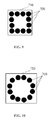
- FIG. 9 is a representational diagram illustrating a square configuration of motion means
- FIG. 10 is a representational diagram illustrating a circular configuration of motion means
- FIG. 11 is a block diagram showing an operating environment in which embodiments of the present invention may be employed for applying RMAs onto skin, using motion means with dispersed contact points;
- FIG. 12 is a block diagram illustrating an operating environment in which embodiments of the present invention may be employed for applying RMAs onto skin through communications over a network, using motion means with dispersed contact points;
- FIG. 13 is a block diagram illustrating an operating environment in which embodiments of the present invention may be employed for applying RMAs onto skin through communications over a network and a portable application device, using motion means with dispersed contact points.
- FIG. 14 is a flow chart illustrating the general steps for a process to determine surface texture from scanned data about an area of skin or other human feature
- FIG. 15 is a chart illustrating a configuration of exposures for determining textures.
- the present invention comprises an applicator head for an applicator used with a computer-controlled system and method that scans an area of human skin, identifies unattractive attributes, and applies the RMA, typically with an inkjet printer, to improve the appearance of that area of skin.
- RMA typically with an inkjet printer
- An example applicator head 2 shown in FIG. 1 , covers an area of skin about equal to a single electric razor head. Such a size is proven daily to fit in intimate contact across a human face.
- multiple applicator heads 2 may be assembled in a floating mount, just as multiple floating heads are combined in a single electric razor.
- the applicator head 2 comprises the following elements, as illustrated in FIG. 2 .
- the molded case 4 A and 4 B has rubber “O” type rings for waterproofing, so that the applicator head 2 can be run under the faucet for cleaning, like a razor.
- the inkjet printer head 8 can be maintained this way, which is not an option in normal printers.
- the applicator head 2 may “park” for storage on a stand that would cap the applicator head 2 .
- the applicator head 2 is moved across the skin by means of a floating ring 6 with elements with dispersed raised contact points. These contact points maintain a proper distance from the surface to be treated, reduce the influence of outside light during scanning, and limit smudging during deposition.
- dispersed raised contact points are pounce wheels which are discussed below.
- a very thin inkjet head 8 illustrated in FIG. 2 , fits perpendicularly to the skin into case groove 10 .
- a field lens 12 assembly with LED assembly 13 provides telecentric viewing so that size is independent of distance and the view fits around the inkjet head. It fits into case groove 14 and helps protect the electronics behind the lens from water and dirt.
- the camera module 16 may be a module made for mobile devices such as cell phones.
- the newer of these modules have 3 megapixels and above. In covering an area half an inch across, just a 1 megapixel camera would have 4 times the resolution of the human eye at 10 inches.
- a replaceable cosmetics reservoir 20 and ink is shown only as a block, but it should have a visually appealing and protectable design because it is what consumers would actually buy repeatedly, like razor blades.
- the cosmetics reservoir 20 may contain multiple separate RMA colors that may be mixed to achieve desired effects. In another embodiment, it may contain a single RMA color premixed to achieve a desired aim color or effect.
- the applicator head 2 is attached to a computer with a cable.
- a data and power cable 22 is required.
- a USB 2.0 cable may be used.
- a consumer computer 24 is required. Almost any newer computer configured correctly with enough disk memory, good display, and a USB port may be used.
- Software 26 is required that runs on the computer 24 and provides the functionality for scanning an area of a human feature, such as skin, calculating cosmetic enhancements, tracking registration, and applying the RMA, explained in detail in the cross-referenced application and outlined below.
- the applicator head 2 enables RMA applications that are like conventional cosmetic applications in the sense that the user actually chooses an aim color and “brushes” it on the desired area. This allows a user to select an “aim” skin color, and then deposit to that density. By optical feedback on each frexel (area of human skin), RMA, such as ink or dye, is deposited on each pass until that density is reached. Then no more dye is deposited on subsequent passes. The user may choose to change the aim color manually while applying to different parts of the skin, just as current art requires different colors of blush to be manually selected and applied to different parts of the face to achieve a shaded effect.
- RMA such as ink or dye
- area of skin is used to represent any human feature to be enhanced.
- Step 1000 in FIG. 3 Choosing an Aim Color.
- a user employs an interface on the computer 24 , shown in FIG. 2 , to select an “aim” skin color to be achieved through an appropriate mix of separate RMA colors contained in the cosmetic reservoir 20 .
- controls on the applicator may be used to select the aim color.
- an applicator may contain premixed RMA for a single aim color, and different applicators may contain different single aim colors. For example, one user might buy an applicator with a light RMA aim color, and another user might buy a different applicator with a darker aim color.
- Step 1002 in FIG. 3 Moving the Applicator Containing the Applicator Head 2 Over the Area to be Enhanced.
- the user moves the applicator containing the applicator head 2 , shown in FIG. 2 , over an area of skin 302 , shown in FIG. 4 , to be enhanced.
- the applicator head 2 shown in FIG. 2
- data from the skin under the applicator is immediately seen as a “current” view.
- Step 1004 in FIG. 3 Capturing Images of the Area to be Enhanced.
- overlapping images 32 are captured by the camera module 16 , shown in FIG. 2 , at least 10 per second. Most of the image at each capture is redundant with the previous capture.
- Step 1006 in FIG. 3 Using Landmarks on the Area to be Enhanced to Provide a Current View of the Area.
- landmarks or “skinmarks” on the area of skin 302 , shown in FIG. 4
- software 26 shown in FIG. 2 , tracks relative movement of the applicator and combines images in computer memory to give an expanded current view of the skin, using only views from the current application session. For example, pores, moles, scars, lines, wrinkles, age spots, sun damage, freckles, color variations, contours of features, textural variations such as bumps, and many other aspects of human features may be used as landmarks.
- An application session is defined to start when the applicator touches the skin and to end when it is retracted.
- the applicator is retracted from the skin, in this mode, all knowledge is erased, and the next application session starts fresh by again placing the applicator some place on the skin and manually sweeping it around an area.
- this current view can cover a large area of skin 302 and develop momentary strategies for partial and overlapping deposition on each sweep.
- Whole-body makeup may be accomplished through multiple sweeps without retracting the applicator from the skin.
- the software 26 shown in FIG. 2 , must be able to determine that a skin defect is underneath the inkjet head 8 at the moment the inkjet head 8 needs to be fired, even though at that precise moment the inkjet head 8 is covering the skin defect from view. As shown in FIG. 5 , this requires knowledge of applicator head 2 position relative to real skin 36 , and a mapping from real skin 36 to abstract layers 38 in computer memory that model that skin, describe aesthetic choices, guide execution strategies, and track long term changes. The positional information provided by the skinmarks described above enables the software 26 , shown in FIG. 2 , to keep the applicator head 2 , the area of skin 302 , shown in FIG. 4 , and computer models in register.
- Step 1008 in FIG. 3 Calculating Enhancements for the Area Represented by the Current View.
- the software 26 calculates cosmetic enhancements to the area of skin 302 , shown in FIG. 4 , using the methods described in the cross-referenced patent application.
- Step 1010 in FIG. 3 Applying RMA to the Area Represented by the Current View.
- RMA such as ink or dye
- the cosmetic reservoir 20 shown in FIG. 2
- RMA is deposited by the inkjet head 8 onto the area of skin shown in the current view, for example the area of skin 302 shown in FIG. 4 , to achieve desired cosmetic enhancement.
- the RMA is deposited on each pass of the applicator over the area of skin 302 until the chosen aim color is reached. Then no more dye is deposited on subsequent passes.
- the applicator of the present invention may be used to apply other substances than RMAs, for example medically beneficial compounds or live skin.
- FIG. 6A and FIG. 6B illustrate a pounce wheel 7 , which is a wheel with points around its outer rim.
- pounce wheels 7 have been used to transfer a design onto a surface.
- a pounce wheel 7 on a handle is rolled over an object and leaves holes in the object's surface, and chalk or another marker is then rubbed over the surface to reveal the holes.
- pounce wheels 7 are used for tracing regular designs onto wood for wood-burning or carving.
- FIG. 6B illustrates a view of a pounce wheel 7 at an angle.
- FIG. 7 illustrates a ball 704 with dispersed points
- FIG. 8 a comb-like walker 706 .
- the floating ring 6 shown in FIG. 2 has multiple micro pounce wheels 7 , shown in FIG. 6A and FIG. 6B , around the rim.
- the height of the points maintains a proper distance from the surface for both scanning and inkjet deposition.
- the pounce wheels 7 shown in FIG. 2 , also reduce the amount of outside light entering around the base of the applicator to prevent distorting the accuracy of the scanning.
- the points on the pounce wheels 7 limit contact of the applicator head 2 with the cosmetics being deposited, to prevent smudging. Thus, they will typically leave behind minimal deposits of the RMA as they are moved over surfaces.
- the pounce wheels 7 should be made of durable non-absorptive and hydrophobic material, for example silicon rubber or Teflon, so that they last and do not absorb the RMA. Their heights should also be low, for example 3/16 of an inch (4.8 mm). The use of low heights keeps the system close to the surface so that too much light does not come in underneath the system.
- the pounce wheels 7 may further be colored black to help absorb light. Their widths should be narrow to further reduce the area that comes into contact with the RMA. Their points should not be very sharp, so that they will not easily puncture surfaces such as skin.
- the pounce wheels 7 may be mounted on thin wires serving as axles.
- twelve pounce wheels may be mounted on each side of the floating ring 6 .
- a non-contact, electrostatic wipe (not shown) may be used to blow off the RMA from the pounce wheels 7 .
- Still other geometrical shapes with dispersed contact points may also be used.
- Motion means with dispersed contact points are useful for the present invention in several ways.
- the height of the contact points can be used to maintain proper distance from the surface. During scanning, they may be used to maintain a proper distance from the surface to be scanned to ensure effective scanning During deposition, they may also be used to maintain a proper distance from the surface to be enhanced by application with the RMA and so ensure proper application.
- the configuration of the dispersed contact points can be used to reduce the amount of outside light entering around the base of the applicator and scanner, to prevent distorting the accuracy of the scanning.
- the contact points serve a baffle to block outside light.
- the dispersion and sharpness of the contact points can be used to limit contact with the RMA on the surface being enhanced, reducing smudging.
- Other motion means such as a shroud that simply drags across the surface or wheel with flat rims without raised points, would typically cause greater smudging.
- Motion means with dispersed contact points are especially useful during multiple-pass enhancement, when the applicator must be moved more than once over a freshly applied RMA that would smudge easily.
- motion means 700 with dispersed contact points may be mounted in a square pattern on a housing side 710 .
- these motion means 700 may be mounted in a circular pattern, as shown in FIG. 10 , as well as in other useful patterns, for example a rectangle.
- the motion means 700 should be made of durable non-absorptive and hydrophobic material, for example silicon rubber or Teflon, so that they last do not absorb the RMA. Thus, they will typically leave behind minimal deposits of the RMA as they are moved over surfaces.
- Their heights should also be low, for example 3/16 of an inch. The use of low heights keeps elements of the system close to the surface so that too much light doesn't come in underneath the system. Their widths should be narrow to further reduce the area that comes into contact with the RMA
- Multiple contact points may be used to achieve the advantages explained above, including baffling light.
- twelve pounce wheels or balls may be mounted on a side, as shown in FIG. 9 and FIG. 10 .
- a hundred comb-like walkers may be mounted in a circle on a side.
- the motion means 700 is preferably colored black to help absorb light.
- FIG. 11 shows an operating environment in which embodiments of the present invention may be employed for applying RMAs onto skin, using motion means 700 with dispersed contact points.
- the motion means 700 may be used on
- FIG. 12 shows an operating environment in which embodiments of the present invention may be employed for applying RMAs onto skin through communications over a network, using motion means 700 with dispersed contact points. Again, the motion means 700 may be used on
- FIG. 13 shows an operating environment in which embodiments of the present invention may be employed for applying RMAs onto skin through communications over a network and a portable application device, using motion means 700 with dispersed contact points.
- the motion means 700 may be used on the side of the application device 246 that comes into contact with the surface to be treated, such as an area of skin 302 .
- the application device 246 further comprises both an inkjet printer 242 and a scanner 220 .
- the present invention comprises a method of differential lighting that can be used to determine surface texture from scanned data about an area of skin or other human feature.
- this method may be used with a computer-controlled system and method that scans an area of human skin, identifies unattractive attributes, and applies RMA, typically with an inkjet printer, to improve the appearance of that area of skin.
- RMA typically with an inkjet printer
- the present invention is an innovation comprising a method of differential lighting that, in an embodiment, may be employed using this computer-controlled system and method and applicator head.
- area of skin is used to represent any human feature to be enhanced cosmetically.
- a plurality of light sources such as LEDs, are provided, such that each light source represents a directional orientation with respect to the housing.
- one directional orientation is a North-South-East-West orientation where one or more lights represents each of those directions.
- Another directional orientation is a circular alignment of light sources such as three light sources arranged about 120 degrees apart. These three sources may be one or more LED.
- a field lens 12 with LED assembly 13 provides telecentric viewing so that size is independent of distance and the view fits around the inkjet head. It fits into case groove 14 and helps protect the electronics behind the lens from water and dirt.
- the LEDs are configured on a North/South and East/West alignment so that one or more LEDs representing each of those directions may be cycled on an off.
- FIG. 14 The general steps of the present invention's method of using differential lighting to determine surface texture from scanned data about an area of skin are illustrated in FIG. 14 .
- Step 2010 in FIG. 14 Using Varying Lighting Configurations to Capture Images in a Cycle
- Images are scanned in a cycle by the applicator head 2 , shown in FIG. 2 , which comprises lighting means and one or more cameras 16 .
- the lighting means comprise a field lens 12 and LEDs 13 .
- each image represents an exposure 40 , shown in FIG. 15 , that is captured in 1/60 second in the US to null out the 120 Hz flicker of ambient fluorescent lighting leaking under the edges of the floating ring 6 , shown in FIG. 2 , during scanning.
- each exposure 40 in one example lighting cycle represents a different configuration or lighting mode of flashed and unflashed LEDs 13 , shown in FIG. 2 .
- the exposures 40 in a cycle are arbitrarily labeled as follows:
- every third exposure 40 is D (Dark), an exposure captured with the LEDs 13 , shown in FIG. 2 , or other lighting means, turned off. This is done so that the software 26 , shown in FIG. 2 , can identify edge leakage in the D (Dark) exposure 40 , shown in FIG. 15 , and subtract that edge leakage from calculations.
- Step 2020 in FIG. 14 Stacking Channels of Exposures
- the exposures 40 are co-synchronized in stacks, where each stack is a grouping of data about a P representing a particular instant of time during the scanning. This data may be obtained from directly captured exposures or from interpolated data.
- five channels of exposures 40 , N, S, E, W, and D are stacked in a stack 42 every 1/60 second frame.
- the stacking may be calculated at other time periods, for example 1/15 sec.; 1/20 sec.; or 1/30 sec.
- One channel 44 in each stack 4 may be directly captured by the camera 16 , shown in FIG. 2 .
- the other four channels are then interpolated from data temporally adjacent exposures 40 , shown in FIG. 15 , based on image movement calculated in software 26 , shown in FIG. 2 .
- Such movement may be calculated at video rates by, for example, a hardware motion detection engine in an MPEG encoder, such as the one found in NVIDIA GPUs for mobile devices, or other techniques in CPU software.
- the use of one or more accelerometers associated with the applicator head 2 may provide additional data showing micro-variations in positioning.
- channel 44 may be interpolated from data from one or more temporally adjacent direct exposures 40 . That is, data from either a frame captured before channel 44 or after it, or from an average of the two, may be used for interpolation of channel 44 .
- Interpolations may be derived by simple averaging of data from one or more temporally adjacent frames.
- a weighted average may also be used, where the weight in the average may be higher for a directly captured frame that is closer in temporal position to the frame that is to be derived.
- Step 2040 in FIG. 14 Subtracting the Dark Exposure from Each Stack to Remove Edge Leakage
- the D (Dark) signal is subtracted from the other four. This gives a precise black level, and eliminates the effect of light leaking around the pounce wheels 7 , shown in FIG. 2 , so long as the total light is not so bright as to saturate the camera 16 or the ratio so low as to amplify sensor noise excessively.
- Step 2060 in FIG. 14 Using a Set of Exposures to Generate Albedo and Tilt
- the remaining N, S, E, and W exposures 40 shown in FIG. 15 , in a stack 42 are an overspecified set of three exposures 40 each, which are used to generate three numbers, namely the albedo (color), the north-south tilt, and the east-west tilt of each area of skin.
- the overspecification allows some options to detect and remove specular reflections when the fourth dimension is in disagreement.
- the color is actually three numbers for R, G, and B, while the captured image is reduced to monochrome using the lowest noise combination before calculating tilt.
- the tilt is a complex equation derived from the differential brightness as seen when illuminated by each LED 13 , shown in FIG. 2 , as a function of the four LED configurations. Because the angle struck by each LED 13 varies across the field, the equation changes for each pixel.
- the practical approach to refine the equation is to first reduce the image to a N/S and E/W differential, and then calibrate gains in a matrix empirically by passing the applicator head 2 over a dimpled surface with known dimple depth.
- Step 2080 in FIG. 14 Synchronization of the Derived Data in Computer Memory
- the derived data is stored in the computer memory of computer 24 , shown in FIG. 2 .
- Step 2090 in FIG. 14 Using a Noise Filtering Average
- the stored data is updated using a noise filtering average.
- the method explained above may be adapted for extrapolating the position of the applicator for actual application of the RMA, for example for firing the inkjet head 8 shown in FIG. 2 .
- the view from the leading part of the applicator head 2 would confirm and refine position of the applicator head 2 prior to deposition.
- the “P” value, shown in FIG. 15 would be extrapolated to determine the exact moment to fire the inkjet head 8 , shown in FIG. 2 , because the skin is not visible when directly under the inkjet head 8 .
- the differential of P, shown in FIG. 15 indicating velocity, would be used to determine how rapidly to fire the inkjet head 8 , shown in FIG. 2 .
- the inkjet head 8 would deposit more ink to attain an aim density if the applicator head 2 were moving faster, or deposition would stop if the applicator head 2 were held motionless at the end of a stroke.
- the trailing part of the applicator head 2 would then be used to update the data about color and texture with the effects of the immediately preceding deposition.
- the applicator head 2 is bidirectional, and can be passed back and forth over the skin with continuous deposition. The sensing of the leading and trailing part of the applicator head 2 would alternate according to software's 26 determination of position and direction of movement.
- the molded plastic case 4 shown in FIG. 2 , may be colored black to reduce retro reflections and reverse reflections off the opposite wall relative to a particular LED configuration.
- LEDs 13 may be stacked in a group, or other diffusion techniques may be used to reduce specular glare effects.
- polarization may be highly beneficial to reduce specular glare effects, although this may complicate assembly and require several fold more power and light from the LEDs 13 .
- the term computer is used here in its broadest sense to include personal computers, laptops, telephones with computer capabilities, personal data assistants (PDAs) and servers, and it should be recognized that it could include multiple servers, with storage and software functions divided among the servers.
- PDAs personal data assistants
- a wide array of operating systems, compatible e-mail services, Web browsers and other communications systems can be used to transmit messages among client applications and Web services.
Abstract
Description
-
- the side of the means of
application 240 that comes into contact with the surface to be treated, such as an area ofskin 302, and - the side of the
scanner 220 that comes into contact with the surface to be treated, such as an area ofskin 302.
- the side of the means of
-
- the side of a
printer 241 that comes into contact with the surface to be treated, such as an area ofskin 302, and - the side of the
scanner 220 that comes into contact with the surface to be treated, such as an area ofskin 302.
- the side of a
-
- N (North),
- S (South),
- D (Dark),
- E (East),
- W (West), and
- D (Dark).
Claims (23)
Priority Applications (1)
| Application Number | Priority Date | Filing Date | Title |
|---|---|---|---|
| US13/019,462 US8942775B2 (en) | 2006-08-14 | 2011-02-02 | Handheld apparatus and method for the automated application of cosmetics and other substances |
Applications Claiming Priority (6)
| Application Number | Priority Date | Filing Date | Title |
|---|---|---|---|
| US11/503,806 US8007062B2 (en) | 2005-08-12 | 2006-08-14 | System and method for applying a reflectance modifying agent to improve the visual attractiveness of human skin |
| US88928807P | 2007-02-11 | 2007-02-11 | |
| US88929107P | 2007-02-11 | 2007-02-11 | |
| US88929907P | 2007-02-12 | 2007-02-12 | |
| US12/028,835 US7890152B2 (en) | 2007-02-11 | 2008-02-11 | Handheld apparatus and method for the automated application of cosmetics and other substances |
| US13/019,462 US8942775B2 (en) | 2006-08-14 | 2011-02-02 | Handheld apparatus and method for the automated application of cosmetics and other substances |
Related Parent Applications (1)
| Application Number | Title | Priority Date | Filing Date |
|---|---|---|---|
| US12/028,835 Continuation US7890152B2 (en) | 2006-08-14 | 2008-02-11 | Handheld apparatus and method for the automated application of cosmetics and other substances |
Publications (2)
| Publication Number | Publication Date |
|---|---|
| US20110124989A1 US20110124989A1 (en) | 2011-05-26 |
| US8942775B2 true US8942775B2 (en) | 2015-01-27 |
Family
ID=52392464
Family Applications (1)
| Application Number | Title | Priority Date | Filing Date |
|---|---|---|---|
| US13/019,462 Expired - Fee Related US8942775B2 (en) | 2006-08-14 | 2011-02-02 | Handheld apparatus and method for the automated application of cosmetics and other substances |
Country Status (1)
| Country | Link |
|---|---|
| US (1) | US8942775B2 (en) |
Cited By (18)
| Publication number | Priority date | Publication date | Assignee | Title |
|---|---|---|---|---|
| US20170004635A1 (en) * | 2006-08-14 | 2017-01-05 | Albert D. Edgar | System and Method for Applying a Reflectance Modifying Agent to Change a Person's Appearance Based on a Digital Image |
| US20170256084A1 (en) * | 2014-09-30 | 2017-09-07 | Tcms Transparent Beauty, Llc | Precise application of cosmetic looks from over a network environment |
| US10016046B2 (en) | 2005-08-12 | 2018-07-10 | Tcms Transparent Beauty, Llc | System and method for applying a reflectance modifying agent to improve the visual attractiveness of human skin |
| US10092082B2 (en) | 2007-05-29 | 2018-10-09 | Tcms Transparent Beauty Llc | Apparatus and method for the precision application of cosmetics |
| US10486174B2 (en) | 2007-02-12 | 2019-11-26 | Tcms Transparent Beauty Llc | System and method for applying a reflectance modifying agent electrostatically to improve the visual attractiveness of human skin |
| US10933156B2 (en) | 2018-02-01 | 2021-03-02 | The Procter & Gamble Company | System and method for dispensing material |
| US10945515B2 (en) | 2017-06-16 | 2021-03-16 | The Procter & Gamble Company | Personal care device with audible feedback |
| US11076675B2 (en) | 2017-06-16 | 2021-08-03 | The Procter & Gamble Company | Method for camouflaging tonal imperfections |
| US11077689B2 (en) | 2015-12-07 | 2021-08-03 | The Procter & Gamble Company | Systems and methods for providing a service station routine |
| US11083672B2 (en) | 2018-02-01 | 2021-08-10 | The Procter & Gamble Company | Cosmetic ink composition comprising a surface tension modifier |
| US11090474B2 (en) | 2018-12-27 | 2021-08-17 | Johnson & Johnson Consumer Inc. | Device and method for application of topical compositions guided by projected fiducials |
| US11090238B2 (en) | 2017-06-16 | 2021-08-17 | The Procter & Gamble Company | Array of cosmetic compositions for camouflaging tonal imperfections |
| US11110257B2 (en) | 2018-12-27 | 2021-09-07 | Johnson & Johnson Consumer Inc. | Device and method for selective application of topical composition using dynamic threshold values |
| US11116302B2 (en) | 2015-06-11 | 2021-09-14 | The Procter & Gamble Company | Apparatus and methods for modifying keratinous surfaces |
| USRE49230E1 (en) | 2015-06-11 | 2022-10-04 | The Procter & Gamble Company | Cartridges for use in an apparatus for modifying keratinous surfaces |
| US11590782B2 (en) | 2015-12-07 | 2023-02-28 | The Procter & Gamble Company | Systems and methods for providing a service station routine |
| US11833236B2 (en) | 2018-02-01 | 2023-12-05 | The Procter And Gamble Company | Heterogenous cosmetic ink composition for inkjet printing applications |
| US11857665B2 (en) | 2018-02-01 | 2024-01-02 | The Procter And Gamble Company | Stable cosmetic ink composition |
Families Citing this family (12)
| Publication number | Priority date | Publication date | Assignee | Title |
|---|---|---|---|---|
| TR201901658T4 (en) | 2008-05-20 | 2019-02-21 | Univ Health Network | EQUIPMENT AND METHOD FOR FLUORESCENT-BASED IMAGING AND MONITORING |
| FR2933582B1 (en) * | 2008-07-10 | 2011-10-07 | Oreal | DEVICE FOR TREATING HUMAN KERATINIC MATERIALS |
| FR2933581B1 (en) * | 2008-07-10 | 2011-12-02 | Oreal | MAKE-UP METHOD AND DEVICE FOR IMPLEMENTING SUCH A METHOD |
| FR2933583B1 (en) * | 2008-07-10 | 2011-10-07 | Oreal | DEVICE FOR APPLYING A COMPOSITION ON HUMAN KERATINIC MATERIALS |
| FR2933611B1 (en) * | 2008-07-10 | 2012-12-14 | Oreal | MAKE-UP PROCESS AND DEVICE FOR IMPLEMENTING SUCH A METHOD |
| US10390601B2 (en) * | 2014-01-05 | 2019-08-27 | Je Matadi, Inc | System and method for applying cosmetics |
| JP2017526617A (en) * | 2014-06-13 | 2017-09-14 | ザ プロクター アンド ギャンブル カンパニー | Treatment composition, apparatus and method for modifying keratinous surface |
| CN115919256A (en) | 2014-07-24 | 2023-04-07 | 大学健康网络 | Data collection and analysis for diagnostic purposes |
| US10188193B2 (en) * | 2014-07-25 | 2019-01-29 | The Procter & Gamble Company | Applicator heads for handheld treatment apparatus for modifying keratinous surfaces |
| EP4013294A1 (en) * | 2019-08-16 | 2022-06-22 | Johnson & Johnson Consumer Inc. | Device and method for application of cosmetic compositions through a grated end effector |
| KR102199603B1 (en) * | 2020-09-09 | 2021-01-07 | 주식회사 티씨엠에스 | Film clip and film stretching apparatus including the same for manufacturing separation membrane |
| US11893826B2 (en) | 2021-03-26 | 2024-02-06 | L'oreal | Determining position of a personal care device relative to body surface |
Citations (111)
| Publication number | Priority date | Publication date | Assignee | Title |
|---|---|---|---|---|
| US4190056A (en) | 1977-10-31 | 1980-02-26 | General Medical Company | Method and means for recording sweat gland activity |
| US4401122A (en) | 1979-08-02 | 1983-08-30 | Children's Hospital Medical Center | Cutaneous methods of measuring body substances |
| JPS59171280U (en) | 1983-05-02 | 1984-11-15 | 三谷セキサン株式会社 | perforated tube |
| US4628356A (en) | 1984-10-15 | 1986-12-09 | Imagex, Inc. | Digital X-ray scanner |
| US4807991A (en) | 1986-04-07 | 1989-02-28 | Electro-Organic Company | Method of inspecting and repairing a structural defect in the surface of an object |
| US4882492A (en) | 1988-01-19 | 1989-11-21 | Biotronics Associates, Inc. | Non-invasive near infrared measurement of blood analyte concentrations |
| US5027817A (en) | 1989-06-22 | 1991-07-02 | New York University | Statistical based display for positron emission tomography scans |
| US5156479A (en) | 1988-12-16 | 1992-10-20 | Yoshino Kogyosho Co., Ltd. | Cosmetic applicator brush having a reservoir and insulated, pressurized chamber |
| US5241468A (en) | 1989-04-13 | 1993-08-31 | Vanguard Imaging Ltd. | Apparatus and method for spectral enhancement of body-surface images to improve sensitivity of detecting subtle color features |
| US5268166A (en) | 1991-07-15 | 1993-12-07 | Elizabeth Arden Company, Division Of Conopco, Inc. | Cosmetic application system |
| US5836872A (en) | 1989-04-13 | 1998-11-17 | Vanguard Imaging, Ltd. | Digital optical visualization, enhancement, quantification, and classification of surface and subsurface features of body surfaces |
| JPH1119050A (en) | 1997-07-01 | 1999-01-26 | Nippon Colin Co Ltd | Image transmitting device for medical treatment |
| JPH1119051A (en) | 1997-07-07 | 1999-01-26 | Nippon Colin Co Ltd | Image transmitting device for medical treatment |
| US5931166A (en) | 1998-12-22 | 1999-08-03 | Weber; Paul J. | Fingernail decorating |
| US6021344A (en) | 1996-12-04 | 2000-02-01 | Derma Technologies, Inc. | Fluorescence scope system for dermatologic diagnosis |
| JP2000139846A (en) | 1998-11-02 | 2000-05-23 | Jena Optronik Gmbh | Method and device for creating diagnostic data in degree of wound to skin tissue of patient |
| US6111653A (en) | 1995-08-07 | 2000-08-29 | Dia-Stron Limited | Translucency measurement |
| US6122042A (en) | 1997-02-07 | 2000-09-19 | Wunderman; Irwin | Devices and methods for optically identifying characteristics of material objects |
| US6151031A (en) | 1996-09-09 | 2000-11-21 | Hewlett-Packard Company | Map builder system and method for enabling generic interfacing of an application with a display map generation process in a management system |
| JP2000331167A (en) | 1999-05-25 | 2000-11-30 | Medeikku Engineering:Kk | Method and device for collating facial image |
| US6208749B1 (en) | 1997-02-28 | 2001-03-27 | Electro-Optical Sciences, Inc. | Systems and methods for the multispectral imaging and characterization of skin tissue |
| WO2001026735A1 (en) | 1999-10-08 | 2001-04-19 | Ultra Cure Ltd. | A method and device for affecting an object by accoustic radiation |
| JP2001112722A (en) | 1999-10-19 | 2001-04-24 | Shiseido Co Ltd | Surface state analyzing method |
| US6250927B1 (en) | 1999-11-29 | 2001-06-26 | Jean Narlo | Cosmetic application training system |
| WO2001049360A1 (en) | 1999-12-30 | 2001-07-12 | Pearl Technology Holdings, Llc. | Skin decoration apparatus and method |
| US6286517B1 (en) | 1998-12-22 | 2001-09-11 | Pearl Technology Holdings, Llc | Fingernail and toenail decoration using ink jets |
| US6292277B1 (en) | 1998-10-16 | 2001-09-18 | Lextron Systems, Inc. | Method and apparatus for creating a white-light interference hologram from PC input photographic data |
| US6293284B1 (en) | 1999-07-07 | 2001-09-25 | Division Of Conopco, Inc. | Virtual makeover |
| US6295737B2 (en) | 1998-01-27 | 2001-10-02 | Eastman Kodak Company | Apparatus and method for marking a contoured surface having complex topology |
| WO2001077976A2 (en) | 2000-03-28 | 2001-10-18 | Eyeweb, Inc. | Image segmenting to enable electronic shopping for wearable goods and cosmetic services |
| US6312124B1 (en) | 1999-10-27 | 2001-11-06 | Hewlett-Packard Company | Solid and semi-flexible body inkjet printing system |
| US20010040982A1 (en) | 1997-10-29 | 2001-11-15 | Lg Electronics Inc. | Object extracting method using motion picture |
| FR2810761A1 (en) | 2000-06-26 | 2001-12-28 | Oreal | Cosmetic treatment method for care, make-up or coloring of the human body, uses image processing to identify surface of part of body to be treated, and uses a computer to control the path of a treatment head |
| JP2002017689A (en) | 2000-07-07 | 2002-01-22 | Naris Cosmetics Co Ltd | Method of measuring and evaluating quality sensation of skin, and use of compound showing effectiveness by this method |
| EP1184663A2 (en) | 2000-09-01 | 2002-03-06 | Spectron Tech Co., Ltd. | Method and apparatus for measuring skin moisture |
| US20020054714A1 (en) | 2000-11-03 | 2002-05-09 | Unilever Home & Personal Care Usa, Division Of Conopco, Inc. | Method of evaluating cosmetic products on a consumer with future predictive transformation |
| US20020064302A1 (en) | 2000-04-10 | 2002-05-30 | Massengill R. Kemp | Virtual cosmetic autosurgery via telemedicine |
| EP1210909A2 (en) | 2000-11-29 | 2002-06-05 | L'oreal | Process for acquiring image data relating to an external body portion and/or a product applied thereto |
| US20020081003A1 (en) | 2000-12-27 | 2002-06-27 | Sobol Robert E. | System and method for automatically enhancing graphical images |
| US20020107456A1 (en) | 2000-08-01 | 2002-08-08 | L'oreal | Method of acquiring an image of a non-dermatoglyphic zone of the skin or of a zone of the hair by means of acquisition apparatus including a non-optical sensor |
| US20020105662A1 (en) | 1998-12-21 | 2002-08-08 | Eastman Kodak Company | Method and apparatus for modifying a portion of an image in accordance with colorimetric parameters |
| US6436127B1 (en) | 1997-10-08 | 2002-08-20 | The General Hospital Corporation | Phototherapy methods and systems |
| JP2002263084A (en) | 2000-11-29 | 2002-09-17 | L'oreal Sa | Method for diagnosing state of outside part of body and feature of product applied to outside part of body |
| US20020155069A1 (en) | 2000-06-26 | 2002-10-24 | Francis Pruche | Cosmetic treatment and device |
| US20020172419A1 (en) | 2001-05-15 | 2002-11-21 | Qian Lin | Image enhancement using face detection |
| US6487440B2 (en) | 1998-07-08 | 2002-11-26 | Lifespex, Inc. | Optical probe having and methods for difuse and uniform light irradiation |
| US20020176926A1 (en) | 1995-06-06 | 2002-11-28 | Pletcher Timothy Allen | Method and apparatus for electrostatically depositing a medicament powder upon predefined regions of a substrate |
| US6502583B1 (en) | 1997-03-06 | 2003-01-07 | Drdc Limited | Method of correcting face image, makeup simulation method, makeup method makeup supporting device and foundation transfer film |
| JP2003052642A (en) | 2001-08-13 | 2003-02-25 | Shiseido Co Ltd | Detector for epidermis-dermis interface of skin |
| JP2003057169A (en) | 2001-08-13 | 2003-02-26 | Shiseido Co Ltd | Three-dimensional image generation apparatus for skin |
| JP2003057170A (en) | 2001-08-13 | 2003-02-26 | Shiseido Co Ltd | Melanin evaluation apparatus |
| US20030045799A1 (en) | 2001-07-09 | 2003-03-06 | L'oreal | Device, system and method for observing a typological characteristic of the body |
| US20030050561A1 (en) | 2001-07-09 | 2003-03-13 | L'oreal | System and method for evaluating a characteristic of body typology |
| US20030053685A1 (en) | 2001-06-01 | 2003-03-20 | Canon Kabushiki Kaisha | Face detection in colour images with complex background |
| US20030060810A1 (en) | 2000-02-16 | 2003-03-27 | Diego Syrowicz | Method and apparatus for treating and/or removing an undesired presence on the skin of an individual |
| US20030063102A1 (en) | 2001-10-01 | 2003-04-03 | Gilles Rubinstenn | Body image enhancement |
| US20030067545A1 (en) | 2001-08-29 | 2003-04-10 | L'oreal | Device and method for acquiring an image of a portion of the human body |
| EP1304056A2 (en) | 2001-10-22 | 2003-04-23 | Hewlett-Packard Company | Cosmetic applicator |
| US6554452B1 (en) | 1997-08-19 | 2003-04-29 | Ppt Vision, Inc. | Machine-vision ring-reflector illumination system and method |
| US20030100837A1 (en) | 1997-08-26 | 2003-05-29 | Ihor Lys | Precision illumination methods and systems |
| US6575751B1 (en) | 1998-11-03 | 2003-06-10 | Shade Analyzing Technologies, Inc. | Interactive dental restorative network |
| US20030108228A1 (en) | 2001-03-02 | 2003-06-12 | L'oreal | Process, system, and kit for evaluating the relief of the skin with a substrate |
| US6578276B2 (en) | 1998-01-27 | 2003-06-17 | Eastman Kodak Company | Apparatus and method for marking multiple colors on a contoured surface having a complex topography |
| US20030130575A1 (en) | 1991-10-18 | 2003-07-10 | Ashvin Desai | Method and apparatus for tissue treatment with laser and electromagnetic radiation |
| US6641578B2 (en) | 2000-06-28 | 2003-11-04 | Nidek Co., Ltd. | Laser treatment apparatus |
| US20030208190A1 (en) | 2001-07-20 | 2003-11-06 | Cynthia Roberts | Methods and instruments for refractive ophthalmic surgery |
| US20030223622A1 (en) | 2002-05-31 | 2003-12-04 | Eastman Kodak Company | Method and system for enhancing portrait images |
| US20030229514A2 (en) | 1992-11-17 | 2003-12-11 | Stephen Brown | Multi-user remote health monitoring system with biometrics support |
| US20040005086A1 (en) | 2002-07-03 | 2004-01-08 | Equinox Corporation | Method and apparatus for using thermal infrared for face recognition |
| US6706035B2 (en) | 2001-07-27 | 2004-03-16 | Koninklijke Phillips Electronics N.V. | Skin treating device comprising a processor for determination of the radiation pulse dose |
| JP2004105748A (en) | 2002-07-09 | 2004-04-08 | Ric:Kk | Digital zooming skin diagnosing device |
| WO2004028420A1 (en) | 2002-09-26 | 2004-04-08 | Pharmacia Corporation | Method for ophtalmic administration of medicament |
| US6719467B2 (en) | 2001-04-30 | 2004-04-13 | Hewlett-Packard Development Company, L.P. | Floor printer |
| US20040125996A1 (en) | 2002-12-27 | 2004-07-01 | Unilever Home & Personal Care Usa, Division Of Conopco, Inc. | Skin diagnostic imaging method and apparatus |
| US20040170337A1 (en) | 2003-02-28 | 2004-09-02 | Eastman Kodak Company | Method and system for enhancing portrait images that are processed in a batch mode |
| US20040174525A1 (en) | 2003-03-07 | 2004-09-09 | Mullani Nizar A. | Dermoscopy epiluminescence device employing cross and parallel polarization |
| US20040179101A1 (en) * | 2002-12-13 | 2004-09-16 | Gary Bodnar | Method for using an electronic imaging device to measure color |
| US20040201694A1 (en) | 2001-02-07 | 2004-10-14 | Vladimir Gartstein | Noninvasive methods and apparatus for monitoring at least one hair characteristic |
| US6810130B1 (en) * | 1999-09-29 | 2004-10-26 | L'oreal | Apparatus for assisting makeup and an assembly constituted by such apparatus and apparatus for delivering makeup having a predetermined BRDF as selected by the apparatus for assisting makeup |
| WO2004091590A1 (en) | 2003-04-17 | 2004-10-28 | Lts Lohmann Therapie-Systeme Ag | Medical active agent patch optically less visible on skin |
| WO2004095372A1 (en) | 2003-04-22 | 2004-11-04 | Provincia Italiana Della Congregazione Dei Figli Dell'immacolata Concezione - Instituto Dermopatico Dell'immacolata | Automatic detection of skin lesions |
| JP2004315426A (en) | 2003-04-16 | 2004-11-11 | L'oreal Sa | Additive for cosmetic |
| US20040236229A1 (en) | 1999-07-02 | 2004-11-25 | Freeman Jenny E. | Integrated imaging apparatus |
| US20040254546A1 (en) | 2001-11-06 | 2004-12-16 | Lefebvre Marc Andre' | Device for use in measuring and/or analysing at least one parameter of an external body portion |
| US20040267189A1 (en) | 2001-10-24 | 2004-12-30 | Daniela Mavor | Device and method for controlled delivery of active substance into the skin |
| US20050004475A1 (en) | 2003-06-13 | 2005-01-06 | L'oreal | Method of comparing the appearance of a region of the human body at at least two different instants |
| EP1495781A2 (en) | 2003-03-21 | 2005-01-12 | Hewlett-Packard Development Company, L.P. | Cartridge for a device for targeted epithelial delivery of medicinal and related agents |
| US20050010102A1 (en) | 2003-03-20 | 2005-01-13 | Marchesini Renato Angelo | Apparatus for the characterisation of pigmented skin lesions |
| US20050053628A1 (en) | 2001-06-29 | 2005-03-10 | Daniela Montanari | Method and device for the classfication and cosmetic treatment of wrinkles |
| US20050053637A1 (en) | 2003-09-07 | 2005-03-10 | Ma'or Ze'ev | Personalized cosmetics |
| DE202004003148U1 (en) | 2004-03-01 | 2005-03-24 | Merlaku Kastriot | Makeup application device for automatically applying makeup to user, applies makeup liquid or powder in form of fine jet |
| US20050154382A1 (en) | 2003-12-31 | 2005-07-14 | Altshuler Gregory B. | Dermatological treatment with visualization |
| WO2006008414A1 (en) | 2004-07-02 | 2006-01-26 | Biomedical Electronics | Method for parametering a skin treatment device using light sources |
| US7027619B2 (en) | 2001-09-13 | 2006-04-11 | Honeywell International Inc. | Near-infrared method and system for use in face detection |
| EP1677254A1 (en) | 2004-12-30 | 2006-07-05 | GSF-Forschungszentrum für Umwelt und Gesundheit GmbH | Method and device for collimating an energy input beam |
| WO2006074881A1 (en) | 2005-01-14 | 2006-07-20 | Nutrinova Nutrition Specialties & Food Ingredients Gmbh | Mixture of high fructose corn syrup (hfcs 42 or hfcs 55) and high-intensity sweeteners with a taste profile of pure sucrose |
| JP2006271654A (en) | 2005-03-29 | 2006-10-12 | Canon Inc | Cosmetic-application system and method using liquid delivery method |
| US20070016078A1 (en) | 2004-12-06 | 2007-01-18 | Hoyt Clifford C | Systems and methods for in-vivo optical imaging and measurement |
| US20070035815A1 (en) * | 2005-08-12 | 2007-02-15 | Edgar Albert D | System and method for applying a reflectance modifying agent to improve the visual attractiveness of human skin |
| US20070047761A1 (en) | 2005-06-10 | 2007-03-01 | Wasilunas Elizabeth A | Methods Of Analyzing Human Facial Symmetry And Balance To Provide Beauty Advice |
| US7233693B2 (en) | 2003-04-29 | 2007-06-19 | Inforward, Inc. | Methods and systems for computer analysis of skin image |
| US20070203413A1 (en) | 2003-09-15 | 2007-08-30 | Beth Israel Deaconess Medical Center | Medical Imaging Systems |
| JP2007231883A (en) | 2006-03-02 | 2007-09-13 | Toyota Motor Corp | Air fuel ratio control device for internal combustion engine |
| US7382400B2 (en) | 2004-02-19 | 2008-06-03 | Robert Bosch Gmbh | Image stabilization system and method for a video camera |
| US20080194971A1 (en) | 2007-02-12 | 2008-08-14 | Edgar Albert D | System and method for applying a reflectance modifying agent electrostatically to improve the visual attractiveness of human skin |
| US20080193195A1 (en) | 2007-02-11 | 2008-08-14 | Edgar Albert D | Handheld apparatus and method for the automated application of cosmetics and other substances |
| US20080192999A1 (en) | 2007-02-12 | 2008-08-14 | Edgar Albert D | System and method for applying a reflectance modifying agent to change a person's appearance based on a digital image |
| US20080219528A1 (en) | 2007-02-11 | 2008-09-11 | Edgar Albert D | System and method for providing simulated images through cosmetic monitoring |
| US20090025747A1 (en) | 2007-05-29 | 2009-01-29 | Edgar Albert D | Apparatus and method for the precision application of cosmetics |
| US7602942B2 (en) | 2004-11-12 | 2009-10-13 | Honeywell International Inc. | Infrared and visible fusion face recognition system |
| US8610767B2 (en) | 2008-03-18 | 2013-12-17 | Koninklijke Philips N.V. | Apparatus for skin imaging, system for skin analysis |
-
2011
- 2011-02-02 US US13/019,462 patent/US8942775B2/en not_active Expired - Fee Related
Patent Citations (137)
| Publication number | Priority date | Publication date | Assignee | Title |
|---|---|---|---|---|
| US4190056A (en) | 1977-10-31 | 1980-02-26 | General Medical Company | Method and means for recording sweat gland activity |
| US4401122A (en) | 1979-08-02 | 1983-08-30 | Children's Hospital Medical Center | Cutaneous methods of measuring body substances |
| JPS59171280U (en) | 1983-05-02 | 1984-11-15 | 三谷セキサン株式会社 | perforated tube |
| US4628356A (en) | 1984-10-15 | 1986-12-09 | Imagex, Inc. | Digital X-ray scanner |
| US4807991A (en) | 1986-04-07 | 1989-02-28 | Electro-Organic Company | Method of inspecting and repairing a structural defect in the surface of an object |
| US4882492A (en) | 1988-01-19 | 1989-11-21 | Biotronics Associates, Inc. | Non-invasive near infrared measurement of blood analyte concentrations |
| US5156479A (en) | 1988-12-16 | 1992-10-20 | Yoshino Kogyosho Co., Ltd. | Cosmetic applicator brush having a reservoir and insulated, pressurized chamber |
| US5241468A (en) | 1989-04-13 | 1993-08-31 | Vanguard Imaging Ltd. | Apparatus and method for spectral enhancement of body-surface images to improve sensitivity of detecting subtle color features |
| US5836872A (en) | 1989-04-13 | 1998-11-17 | Vanguard Imaging, Ltd. | Digital optical visualization, enhancement, quantification, and classification of surface and subsurface features of body surfaces |
| US5027817A (en) | 1989-06-22 | 1991-07-02 | New York University | Statistical based display for positron emission tomography scans |
| US5268166A (en) | 1991-07-15 | 1993-12-07 | Elizabeth Arden Company, Division Of Conopco, Inc. | Cosmetic application system |
| US20030130575A1 (en) | 1991-10-18 | 2003-07-10 | Ashvin Desai | Method and apparatus for tissue treatment with laser and electromagnetic radiation |
| US20030229514A2 (en) | 1992-11-17 | 2003-12-11 | Stephen Brown | Multi-user remote health monitoring system with biometrics support |
| US20020176926A1 (en) | 1995-06-06 | 2002-11-28 | Pletcher Timothy Allen | Method and apparatus for electrostatically depositing a medicament powder upon predefined regions of a substrate |
| US6111653A (en) | 1995-08-07 | 2000-08-29 | Dia-Stron Limited | Translucency measurement |
| US6151031A (en) | 1996-09-09 | 2000-11-21 | Hewlett-Packard Company | Map builder system and method for enabling generic interfacing of an application with a display map generation process in a management system |
| US6021344A (en) | 1996-12-04 | 2000-02-01 | Derma Technologies, Inc. | Fluorescence scope system for dermatologic diagnosis |
| US6122042A (en) | 1997-02-07 | 2000-09-19 | Wunderman; Irwin | Devices and methods for optically identifying characteristics of material objects |
| US6208749B1 (en) | 1997-02-28 | 2001-03-27 | Electro-Optical Sciences, Inc. | Systems and methods for the multispectral imaging and characterization of skin tissue |
| US6502583B1 (en) | 1997-03-06 | 2003-01-07 | Drdc Limited | Method of correcting face image, makeup simulation method, makeup method makeup supporting device and foundation transfer film |
| US20030062058A1 (en) | 1997-03-06 | 2003-04-03 | Ryuichi Utsugi | Method of modifying facial images, makeup simulation method, makeup method, makeup support apparatus and foundation transfer film |
| JPH1119050A (en) | 1997-07-01 | 1999-01-26 | Nippon Colin Co Ltd | Image transmitting device for medical treatment |
| JPH1119051A (en) | 1997-07-07 | 1999-01-26 | Nippon Colin Co Ltd | Image transmitting device for medical treatment |
| US6554452B1 (en) | 1997-08-19 | 2003-04-29 | Ppt Vision, Inc. | Machine-vision ring-reflector illumination system and method |
| US20030100837A1 (en) | 1997-08-26 | 2003-05-29 | Ihor Lys | Precision illumination methods and systems |
| US6436127B1 (en) | 1997-10-08 | 2002-08-20 | The General Hospital Corporation | Phototherapy methods and systems |
| US20010040982A1 (en) | 1997-10-29 | 2001-11-15 | Lg Electronics Inc. | Object extracting method using motion picture |
| US6295737B2 (en) | 1998-01-27 | 2001-10-02 | Eastman Kodak Company | Apparatus and method for marking a contoured surface having complex topology |
| US6578276B2 (en) | 1998-01-27 | 2003-06-17 | Eastman Kodak Company | Apparatus and method for marking multiple colors on a contoured surface having a complex topography |
| US6487440B2 (en) | 1998-07-08 | 2002-11-26 | Lifespex, Inc. | Optical probe having and methods for difuse and uniform light irradiation |
| US6292277B1 (en) | 1998-10-16 | 2001-09-18 | Lextron Systems, Inc. | Method and apparatus for creating a white-light interference hologram from PC input photographic data |
| JP2000139846A (en) | 1998-11-02 | 2000-05-23 | Jena Optronik Gmbh | Method and device for creating diagnostic data in degree of wound to skin tissue of patient |
| US6575751B1 (en) | 1998-11-03 | 2003-06-10 | Shade Analyzing Technologies, Inc. | Interactive dental restorative network |
| US20020105662A1 (en) | 1998-12-21 | 2002-08-08 | Eastman Kodak Company | Method and apparatus for modifying a portion of an image in accordance with colorimetric parameters |
| US6286517B1 (en) | 1998-12-22 | 2001-09-11 | Pearl Technology Holdings, Llc | Fingernail and toenail decoration using ink jets |
| US5931166A (en) | 1998-12-22 | 1999-08-03 | Weber; Paul J. | Fingernail decorating |
| US6067996A (en) | 1998-12-22 | 2000-05-30 | Pearl I. Llc | Nail decoration using ink jets |
| US6341831B1 (en) | 1999-03-09 | 2002-01-29 | Paul J. Weber | Skin decoration apparatus and method |
| JP2000331167A (en) | 1999-05-25 | 2000-11-30 | Medeikku Engineering:Kk | Method and device for collating facial image |
| US20040236229A1 (en) | 1999-07-02 | 2004-11-25 | Freeman Jenny E. | Integrated imaging apparatus |
| US6293284B1 (en) | 1999-07-07 | 2001-09-25 | Division Of Conopco, Inc. | Virtual makeover |
| US6810130B1 (en) * | 1999-09-29 | 2004-10-26 | L'oreal | Apparatus for assisting makeup and an assembly constituted by such apparatus and apparatus for delivering makeup having a predetermined BRDF as selected by the apparatus for assisting makeup |
| WO2001026735A1 (en) | 1999-10-08 | 2001-04-19 | Ultra Cure Ltd. | A method and device for affecting an object by accoustic radiation |
| JP2001112722A (en) | 1999-10-19 | 2001-04-24 | Shiseido Co Ltd | Surface state analyzing method |
| US6312124B1 (en) | 1999-10-27 | 2001-11-06 | Hewlett-Packard Company | Solid and semi-flexible body inkjet printing system |
| US6543893B2 (en) | 1999-10-27 | 2003-04-08 | Hewlett-Packard Development Company, L.P. | Solid and semi-flexible body inkjet printing system |
| US6250927B1 (en) | 1999-11-29 | 2001-06-26 | Jean Narlo | Cosmetic application training system |
| WO2001049360A1 (en) | 1999-12-30 | 2001-07-12 | Pearl Technology Holdings, Llc. | Skin decoration apparatus and method |
| JP2003519019A (en) | 1999-12-30 | 2003-06-17 | パール アイ,エルエルシー | Skin decoration device and method |
| US20030060810A1 (en) | 2000-02-16 | 2003-03-27 | Diego Syrowicz | Method and apparatus for treating and/or removing an undesired presence on the skin of an individual |
| WO2001077976A2 (en) | 2000-03-28 | 2001-10-18 | Eyeweb, Inc. | Image segmenting to enable electronic shopping for wearable goods and cosmetic services |
| US20020064302A1 (en) | 2000-04-10 | 2002-05-30 | Massengill R. Kemp | Virtual cosmetic autosurgery via telemedicine |
| FR2810761A1 (en) | 2000-06-26 | 2001-12-28 | Oreal | Cosmetic treatment method for care, make-up or coloring of the human body, uses image processing to identify surface of part of body to be treated, and uses a computer to control the path of a treatment head |
| US20020155069A1 (en) | 2000-06-26 | 2002-10-24 | Francis Pruche | Cosmetic treatment and device |
| US20040078278A1 (en) | 2000-06-26 | 2004-04-22 | Christophe Dauga | Cosmetic treatment method and device, in particular for care, make-up or colouring |
| JP2004501707A (en) | 2000-06-26 | 2004-01-22 | ロレアル | Beauty treatment method and device, especially for care, makeup or coloring |
| US6641578B2 (en) | 2000-06-28 | 2003-11-04 | Nidek Co., Ltd. | Laser treatment apparatus |
| JP2002017689A (en) | 2000-07-07 | 2002-01-22 | Naris Cosmetics Co Ltd | Method of measuring and evaluating quality sensation of skin, and use of compound showing effectiveness by this method |
| US20020107456A1 (en) | 2000-08-01 | 2002-08-08 | L'oreal | Method of acquiring an image of a non-dermatoglyphic zone of the skin or of a zone of the hair by means of acquisition apparatus including a non-optical sensor |
| EP1184663A2 (en) | 2000-09-01 | 2002-03-06 | Spectron Tech Co., Ltd. | Method and apparatus for measuring skin moisture |
| US20020054714A1 (en) | 2000-11-03 | 2002-05-09 | Unilever Home & Personal Care Usa, Division Of Conopco, Inc. | Method of evaluating cosmetic products on a consumer with future predictive transformation |
| EP1210909A2 (en) | 2000-11-29 | 2002-06-05 | L'oreal | Process for acquiring image data relating to an external body portion and/or a product applied thereto |
| JP2002263084A (en) | 2000-11-29 | 2002-09-17 | L'oreal Sa | Method for diagnosing state of outside part of body and feature of product applied to outside part of body |
| US20020081003A1 (en) | 2000-12-27 | 2002-06-27 | Sobol Robert E. | System and method for automatically enhancing graphical images |
| US20040201694A1 (en) | 2001-02-07 | 2004-10-14 | Vladimir Gartstein | Noninvasive methods and apparatus for monitoring at least one hair characteristic |
| US20030108228A1 (en) | 2001-03-02 | 2003-06-12 | L'oreal | Process, system, and kit for evaluating the relief of the skin with a substrate |
| US6719467B2 (en) | 2001-04-30 | 2004-04-13 | Hewlett-Packard Development Company, L.P. | Floor printer |
| US20020172419A1 (en) | 2001-05-15 | 2002-11-21 | Qian Lin | Image enhancement using face detection |
| US20030053685A1 (en) | 2001-06-01 | 2003-03-20 | Canon Kabushiki Kaisha | Face detection in colour images with complex background |
| US20050053628A1 (en) | 2001-06-29 | 2005-03-10 | Daniela Montanari | Method and device for the classfication and cosmetic treatment of wrinkles |
| US20030050561A1 (en) | 2001-07-09 | 2003-03-13 | L'oreal | System and method for evaluating a characteristic of body typology |
| US20030045799A1 (en) | 2001-07-09 | 2003-03-06 | L'oreal | Device, system and method for observing a typological characteristic of the body |
| US20030208190A1 (en) | 2001-07-20 | 2003-11-06 | Cynthia Roberts | Methods and instruments for refractive ophthalmic surgery |
| US6706035B2 (en) | 2001-07-27 | 2004-03-16 | Koninklijke Phillips Electronics N.V. | Skin treating device comprising a processor for determination of the radiation pulse dose |
| JP2003052642A (en) | 2001-08-13 | 2003-02-25 | Shiseido Co Ltd | Detector for epidermis-dermis interface of skin |
| JP2003057170A (en) | 2001-08-13 | 2003-02-26 | Shiseido Co Ltd | Melanin evaluation apparatus |
| JP2003057169A (en) | 2001-08-13 | 2003-02-26 | Shiseido Co Ltd | Three-dimensional image generation apparatus for skin |
| US20030067545A1 (en) | 2001-08-29 | 2003-04-10 | L'oreal | Device and method for acquiring an image of a portion of the human body |
| US7027619B2 (en) | 2001-09-13 | 2006-04-11 | Honeywell International Inc. | Near-infrared method and system for use in face detection |
| US20030063102A1 (en) | 2001-10-01 | 2003-04-03 | Gilles Rubinstenn | Body image enhancement |
| JP2003210248A (en) | 2001-10-22 | 2003-07-29 | Hewlett Packard Co <Hp> | Cosmetic applicator |
| EP1304056A2 (en) | 2001-10-22 | 2003-04-23 | Hewlett-Packard Company | Cosmetic applicator |
| US20040267189A1 (en) | 2001-10-24 | 2004-12-30 | Daniela Mavor | Device and method for controlled delivery of active substance into the skin |
| US20040254546A1 (en) | 2001-11-06 | 2004-12-16 | Lefebvre Marc Andre' | Device for use in measuring and/or analysing at least one parameter of an external body portion |
| US20030223622A1 (en) | 2002-05-31 | 2003-12-04 | Eastman Kodak Company | Method and system for enhancing portrait images |
| US20040005086A1 (en) | 2002-07-03 | 2004-01-08 | Equinox Corporation | Method and apparatus for using thermal infrared for face recognition |
| JP2004105748A (en) | 2002-07-09 | 2004-04-08 | Ric:Kk | Digital zooming skin diagnosing device |
| WO2004028420A1 (en) | 2002-09-26 | 2004-04-08 | Pharmacia Corporation | Method for ophtalmic administration of medicament |
| US20040179101A1 (en) * | 2002-12-13 | 2004-09-16 | Gary Bodnar | Method for using an electronic imaging device to measure color |
| US20040125996A1 (en) | 2002-12-27 | 2004-07-01 | Unilever Home & Personal Care Usa, Division Of Conopco, Inc. | Skin diagnostic imaging method and apparatus |
| US20060228039A1 (en) | 2003-02-28 | 2006-10-12 | Simon Richard A | Method and system for enhancing portrait images that are processed in a batch mode |
| US20060228040A1 (en) | 2003-02-28 | 2006-10-12 | Simon Richard A | Method and system for enhancing portrait image that are processed in a batch mode |
| US20060228038A1 (en) | 2003-02-28 | 2006-10-12 | Simon Richard A | Method and system for enhancing portrait images that are processed in a batch mode |
| US20060228037A1 (en) | 2003-02-28 | 2006-10-12 | Simon Richard A | Method and system for enhancing portrait images that are processed in a batch mode |
| US20060153470A1 (en) | 2003-02-28 | 2006-07-13 | Simon Richard A | Method and system for enhancing portrait images that are processed in a batch mode |
| US20040170337A1 (en) | 2003-02-28 | 2004-09-02 | Eastman Kodak Company | Method and system for enhancing portrait images that are processed in a batch mode |
| US20040174525A1 (en) | 2003-03-07 | 2004-09-09 | Mullani Nizar A. | Dermoscopy epiluminescence device employing cross and parallel polarization |
| US20050010102A1 (en) | 2003-03-20 | 2005-01-13 | Marchesini Renato Angelo | Apparatus for the characterisation of pigmented skin lesions |
| WO2005123172A1 (en) | 2003-03-21 | 2005-12-29 | Hewlett-Packard Development Company, L.P. | Device for targeted delivery of medicinal, cosmetic, and related agents |
| EP1495781A2 (en) | 2003-03-21 | 2005-01-12 | Hewlett-Packard Development Company, L.P. | Cartridge for a device for targeted epithelial delivery of medicinal and related agents |
| JP2004315426A (en) | 2003-04-16 | 2004-11-11 | L'oreal Sa | Additive for cosmetic |
| RU2336866C2 (en) | 2003-04-17 | 2008-10-27 | Лтс Ломанн Терапи-Зюстеме Аг | Invisible on skin plaster, containing active substance |
| WO2004091590A1 (en) | 2003-04-17 | 2004-10-28 | Lts Lohmann Therapie-Systeme Ag | Medical active agent patch optically less visible on skin |
| WO2004095372A1 (en) | 2003-04-22 | 2004-11-04 | Provincia Italiana Della Congregazione Dei Figli Dell'immacolata Concezione - Instituto Dermopatico Dell'immacolata | Automatic detection of skin lesions |
| US7233693B2 (en) | 2003-04-29 | 2007-06-19 | Inforward, Inc. | Methods and systems for computer analysis of skin image |
| US20050004475A1 (en) | 2003-06-13 | 2005-01-06 | L'oreal | Method of comparing the appearance of a region of the human body at at least two different instants |
| US20050053637A1 (en) | 2003-09-07 | 2005-03-10 | Ma'or Ze'ev | Personalized cosmetics |
| US20070203413A1 (en) | 2003-09-15 | 2007-08-30 | Beth Israel Deaconess Medical Center | Medical Imaging Systems |
| US20050154382A1 (en) | 2003-12-31 | 2005-07-14 | Altshuler Gregory B. | Dermatological treatment with visualization |
| US7382400B2 (en) | 2004-02-19 | 2008-06-03 | Robert Bosch Gmbh | Image stabilization system and method for a video camera |
| DE202004003148U1 (en) | 2004-03-01 | 2005-03-24 | Merlaku Kastriot | Makeup application device for automatically applying makeup to user, applies makeup liquid or powder in form of fine jet |
| EP1763380A1 (en) | 2004-07-02 | 2007-03-21 | Biomedical Electronics | Method for parametering a skin treatment device using light sources |
| WO2006008414A1 (en) | 2004-07-02 | 2006-01-26 | Biomedical Electronics | Method for parametering a skin treatment device using light sources |
| US7602942B2 (en) | 2004-11-12 | 2009-10-13 | Honeywell International Inc. | Infrared and visible fusion face recognition system |
| US20070016078A1 (en) | 2004-12-06 | 2007-01-18 | Hoyt Clifford C | Systems and methods for in-vivo optical imaging and measurement |
| JP2008526284A (en) | 2004-12-30 | 2008-07-24 | ヘルムホルツ・ツェントルム・ミュンヒェン・ドイチェス・フォルシュンクスツェントルム・フューア・ゲズントハイト・ウント・ウムベルト(ゲーエムベーハー) | Method and apparatus for collimating an energy input beam |
| EP1677254A1 (en) | 2004-12-30 | 2006-07-05 | GSF-Forschungszentrum für Umwelt und Gesundheit GmbH | Method and device for collimating an energy input beam |
| JP2008526241A (en) | 2005-01-14 | 2008-07-24 | ニュートリノヴァ ニュートリション スペシャリティーズ アンド フード イングリーディエンツ ゲゼルシャフト ミット ベシュレンクテル ハフツング | Mixture of high fructose corn syrup (HFCS42 or HFCS55) and high intensity sweetener with a taste profile of pure sucrose |
| WO2006074881A1 (en) | 2005-01-14 | 2006-07-20 | Nutrinova Nutrition Specialties & Food Ingredients Gmbh | Mixture of high fructose corn syrup (hfcs 42 or hfcs 55) and high-intensity sweeteners with a taste profile of pure sucrose |
| JP2006271654A (en) | 2005-03-29 | 2006-10-12 | Canon Inc | Cosmetic-application system and method using liquid delivery method |
| US20070047761A1 (en) | 2005-06-10 | 2007-03-01 | Wasilunas Elizabeth A | Methods Of Analyzing Human Facial Symmetry And Balance To Provide Beauty Advice |
| CN101287607B (en) | 2005-08-12 | 2010-09-01 | 里克·B·耶格尔 | System and method for spraying reflectivity modifier to improve skin appearance |
| US20070049832A1 (en) | 2005-08-12 | 2007-03-01 | Edgar Albert D | System and method for medical monitoring and treatment through cosmetic monitoring and treatment |
| US20110270200A1 (en) | 2005-08-12 | 2011-11-03 | Tcms Transparent Beauty Llc | System And Method For Applying A Reflectance Modifying Agent To Improve The Visual Attractiveness Of Human Skin |
| WO2007022095A1 (en) | 2005-08-12 | 2007-02-22 | Yeager Rick B | System and method for applying a reflectance modifying agent to improve the visual attractiveness of human skin |
| US20070035815A1 (en) * | 2005-08-12 | 2007-02-15 | Edgar Albert D | System and method for applying a reflectance modifying agent to improve the visual attractiveness of human skin |
| JP2007231883A (en) | 2006-03-02 | 2007-09-13 | Toyota Motor Corp | Air fuel ratio control device for internal combustion engine |
| US20140050377A1 (en) | 2006-08-14 | 2014-02-20 | Albert D. Edgar | System and Method for Applying a Reflectance Modifying Agent to Change a Persons Appearance Based on a Digital Image |
| US8027505B2 (en) | 2007-02-11 | 2011-09-27 | Tcms Transparent Beauty Llc | System and method for providing simulated images through cosmetic monitoring |
| US20080193195A1 (en) | 2007-02-11 | 2008-08-14 | Edgar Albert D | Handheld apparatus and method for the automated application of cosmetics and other substances |
| US20080219528A1 (en) | 2007-02-11 | 2008-09-11 | Edgar Albert D | System and method for providing simulated images through cosmetic monitoring |
| US7890152B2 (en) | 2007-02-11 | 2011-02-15 | Tcms Transparent Beauty Llc | Handheld apparatus and method for the automated application of cosmetics and other substances |
| US20080192999A1 (en) | 2007-02-12 | 2008-08-14 | Edgar Albert D | System and method for applying a reflectance modifying agent to change a person's appearance based on a digital image |
| US8582830B2 (en) | 2007-02-12 | 2013-11-12 | Tcms Transparent Beauty Llc | System and method for applying a reflectance modifying agent to change a persons appearance based on a digital image |
| US20080194971A1 (en) | 2007-02-12 | 2008-08-14 | Edgar Albert D | System and method for applying a reflectance modifying agent electrostatically to improve the visual attractiveness of human skin |
| US20090025747A1 (en) | 2007-05-29 | 2009-01-29 | Edgar Albert D | Apparatus and method for the precision application of cosmetics |
| US8610767B2 (en) | 2008-03-18 | 2013-12-17 | Koninklijke Philips N.V. | Apparatus for skin imaging, system for skin analysis |
Non-Patent Citations (51)
| Title |
|---|
| "Lehrstuhl für Optik 2004 Annual Report" Jun. 2005 (2005-2006), Lehrstuhl Für Optik, Institute Für Optik, Information and Photonik, Max-Planck-Forschungsgruppe, Universität Erlangen-Nu{umlaut over (r)}nberg, Erlangen, Germany, XP002460048, 2 pages. |
| Anonymous, "Circular Polarizer Films," Internet Article, [Online] 2005, http://www.optigrafix.com/circular.htm [retrieved on Sep. 5, 2008]. |
| Authorized Officer Athina Nickitas-Etienne, International Preliminary Report on Patentability for International Application No. PCT/US2008/053640, mailed Aug. 19, 2009, 5 pages. |
| Authorized Officer Carlos Nicolas, International Search Report and Written Opinion for Application No. PCT/US2008/065168, mailed Sep. 19, 2008, 13 pages. |
| Authorized Officer Dorothee Mulhausen, International Preliminary Report on Patentability for International Application No. PCT/US2006/031657, mailed Feb. 12, 2008, 7 pages. |
| Authorized Officer Jens Clevorn, International Preliminary Report on Patentability and Written Opinion of the International Searching Authority for Application No. PCT/US2008/053528, dated Aug. 11, 2009, 9 pages. |
| Authorized Officer Jens Clevorn, International Search Report for Application No. PCT/US2008/053528, dated Nov. 13, 2008, 4 pages. |
| Authorized Officer Lars-Oliver Romich, International Search Report and the Written Opinion for International Application No. PCT/US2006/031441, mailed Dec. 7, 2007, 14 pages. |
| Authorized Officer Laure Acquaviva, Invitation to Pay Additional Fees and, where applicable, Protest Fees International Application No. PCT/US2008/053527, mailed Jul. 7, 2008, 8 pages. |
| Authorized Officer Michael Eberwein, International Search Report and Written Opinion for International Application No. PCT/US2008/053640, mailed Jun. 3, 2008, 9 pages. |
| Authorized Officer Moritz Knupling, International Search Report for International Application No. PCT/US2006/031441, mailed Dec. 7, 2007, 2 pages. |
| Authorized Officer Nora Lindner, International Preliminary Report on Patentability and Written Opinion of the International Searching Authority for International Application No. PCT/US2006/031441, mailed Feb. 12, 2008, 9 pages. |
| Authorized Officer Simin Baharlou, International Preliminary Report on Patentability and Written Opinion of the International Searching Authority for Application No. PCT/US2008/065168, mailed Dec. 1, 2009, 8 pages. |
| Bon et al; Quantitative and Kinetic Evolution of Wound Healing through Image Analysis; 2000 IEEE Transactions on Medical Imaging, vol. 19, No. 7; Jul. 2000; 767-772. |
| Chiu et al; Fractionated Photothermolysis: The Fraxel 1550-nm Glass Fiber Laser Treatment; Facial Plastic Surgery Clinics of North America (2007), vol. 15, Issue 2; May 2007, 229-237. |
| Chujit Jeamsinkul, "MasqueArray Automatic Makeup Selector/Applicator", Nov. 11, 1998, Rochester Institute of Technology, 79 pages. |
| Cula et al; Bidirectional Imaging and Modeling of Skin Texture; IEEE Engineering of Medicine and Biology Society; Nov. 2004; 1-6. |
| Cula O G et al., "Bidirectional Imaging and Modeling of Skin Texture," IEEE Transactions on Biomedical Engineering, IEEE Service Center, Piscataway, NJ, USA, vol. 51, No. 12, Dec. 1, 2004, pp. 2148-2159. |
| EPO Office Action in App. No. 06 801 295.4, mailed Feb. 3, 2010, 3 pages. |
| EPO Office Action in App. No. 06 801 295.4, mailed Oct. 10, 2011, 5 pages. |
| EPO Office Action in Application No. 06 789 746.2, mailed Apr. 3, 2009, 3 pages. |
| EPO Office Action in Application No. 06 801 295.4, mailed Jun. 10, 2008, 3 pages. |
| European Patent Office Action for Application No. 08 729 481.5, dated Aug. 23, 2010, 5 pages. |
| Examination Report for Canadian Patent Application No. 2,619,706, Jul. 31, 2014, 3 pages. |
| Examination Report for European Application No. 08769826.2, dated Jul. 16, 2013, 6 pages. |
| Examiner's First Report in Application No. 2006279652, mailed Jan. 28, 2011, 2 pages. |
| Examiner's First Report in Application No. 2006279800, mailed Feb. 2, 2011, 2 pages. |
| Examiner's First Report in Application No. 2008260040, mailed Apr. 13, 2012, 2 pages. |
| International Search Report for International Application No. PCT/US2006/031657, mailed Dec. 20, 2006, 2 pages. |
| Laubach et al; Effects of Skin Temperature on Lesion Size in Fractional Photothermolysis; Lasers in Surgery and Medicine; Jan. 2007; 14-18. |
| Mike Topping et al., "The Development of Handy 1, A Robotic System to Assist the Severely Disabled," ICORR '99, Sixth International Conference of Rehabilitation Robotics, Stanford, CA, Jul. 1-2, 1999, pp. 244-249. |
| Mike Topping, "An Overview of the Development of Handy 1, a Rehabilitation Robot to Assist the Severely Disabled" Journal of Intelligent and Robotic Systems, vol. 34, No. 3, 2002, pp. 253-263. |
| Notice of Reasons for Rejection for Application No. 2008-526241, dated Aug. 31, 2011, 7 pages. |
| Notice of Reasons for Rejection for Application No. 2008-526284, dated Apr. 18, 2012, 10 pages. |
| Notice to File a Response in Application No. 10-2008-7006041, dated Jan. 29, 2013, 10 pages. |
| Notice to File a Response in Application No. 10-2008-7006079, dated Aug. 6, 2012, 10 pages. |
| Notice to File a Response in Application No. 10-2008-7006079, dated Jun. 25, 2013, 5 pages. |
| Notification of First Office Action for Application No. 200880009579.0, dated Jul. 14, 2010, 10 pages. |
| Notification of the First Office Action (including translation) in Application No. 200680037560.8, mailed Jul. 17, 2009, 8 pages. |
| Notification of the First Office Action (including translation) in Application No. 200680037564.6, mailed Jul. 31, 2009, 7 pages. |
| Notification of the First Office Action (including translation) in Application No. 200880009069.3, mailed Jul. 1, 2011, 8 pages. |
| Notification of the Second Office Action for Application No. 200880009579.0, dated Mar. 10, 2012, 4 pages. |
| Notification of the Third Office Action for Application No. 200880009579.0, dated Jan. 7, 2013, 8 pages. |
| Office Action for Application No. 2009148819, mailed May 30, 2012, 7 pages. |
| Office Action for Japanese Patent Application No. 2009-549296, Apr. 30, 2013, 12 pages. |
| Office Action for Korean Patent Application No. 10-2009-7019063, Mar. 24, 2014, 8 pages. |
| Railan et al; Laser Treatment of Acne, Psoriasis, Leukoderma and Scars; Seminars in Cutaneous Medicine and Surgery; Dec. 2008; 285-291. |
| Robot News, "Handy1-Rehabilitation robot for the severely disabled; helping you to eat and drink and brush and even do make-up!", posted on Apr. 3, 2006, http://robotnews.wordpress.com/2006/04/03/handy1-rehabiliation-robot-for-the-severely-disabledhelping-you-to-eat-and-drink-and-brush-and-even-do-make-up/, 6 pages. |
| Russian Deputy Chief S.V. Artamonov, Decision on Grant Patent for Invention (including translation) in Application 2008109235, dated Feb. 19, 2009. |
| Russian Official Action (including translation) for Application No. 2008109234, mailed Apr. 2, 2009, 7 pages. |
| Second Examiner's Report in Application No. 2006279652, mailed Nov. 3, 2011, 2 pages. |
Cited By (26)
| Publication number | Priority date | Publication date | Assignee | Title |
|---|---|---|---|---|
| US10016046B2 (en) | 2005-08-12 | 2018-07-10 | Tcms Transparent Beauty, Llc | System and method for applying a reflectance modifying agent to improve the visual attractiveness of human skin |
| US11445802B2 (en) | 2005-08-12 | 2022-09-20 | Tcms Transparent Beauty, Llc | System and method for applying a reflectance modifying agent to improve the visual attractiveness of human skin |
| US11147357B2 (en) | 2005-08-12 | 2021-10-19 | Tcms Transparent Beauty, Llc | System and method for applying a reflectance modifying agent to improve the visual attractiveness of human skin |
| US20170004635A1 (en) * | 2006-08-14 | 2017-01-05 | Albert D. Edgar | System and Method for Applying a Reflectance Modifying Agent to Change a Person's Appearance Based on a Digital Image |
| US10043292B2 (en) * | 2006-08-14 | 2018-08-07 | Tcms Transparent Beauty Llc | System and method for applying a reflectance modifying agent to change a person's appearance based on a digital image |
| US10163230B2 (en) | 2007-02-12 | 2018-12-25 | Tcms Transparent Beauty Llc | System and method for applying a reflectance modifying agent to change a person's appearance based on a digital image |
| US10467779B2 (en) | 2007-02-12 | 2019-11-05 | Tcms Transparent Beauty Llc | System and method for applying a reflectance modifying agent to change a person's appearance based on a digital image |
| US10486174B2 (en) | 2007-02-12 | 2019-11-26 | Tcms Transparent Beauty Llc | System and method for applying a reflectance modifying agent electrostatically to improve the visual attractiveness of human skin |
| US10092082B2 (en) | 2007-05-29 | 2018-10-09 | Tcms Transparent Beauty Llc | Apparatus and method for the precision application of cosmetics |
| US20170256084A1 (en) * | 2014-09-30 | 2017-09-07 | Tcms Transparent Beauty, Llc | Precise application of cosmetic looks from over a network environment |
| US10553006B2 (en) * | 2014-09-30 | 2020-02-04 | Tcms Transparent Beauty, Llc | Precise application of cosmetic looks from over a network environment |
| US11116302B2 (en) | 2015-06-11 | 2021-09-14 | The Procter & Gamble Company | Apparatus and methods for modifying keratinous surfaces |
| USRE49230E1 (en) | 2015-06-11 | 2022-10-04 | The Procter & Gamble Company | Cartridges for use in an apparatus for modifying keratinous surfaces |
| US11077689B2 (en) | 2015-12-07 | 2021-08-03 | The Procter & Gamble Company | Systems and methods for providing a service station routine |
| US11590782B2 (en) | 2015-12-07 | 2023-02-28 | The Procter & Gamble Company | Systems and methods for providing a service station routine |
| US11090238B2 (en) | 2017-06-16 | 2021-08-17 | The Procter & Gamble Company | Array of cosmetic compositions for camouflaging tonal imperfections |
| US11076675B2 (en) | 2017-06-16 | 2021-08-03 | The Procter & Gamble Company | Method for camouflaging tonal imperfections |
| US10945515B2 (en) | 2017-06-16 | 2021-03-16 | The Procter & Gamble Company | Personal care device with audible feedback |
| US11090239B2 (en) | 2018-02-01 | 2021-08-17 | The Procter & Gamble Company | Cosmetic ink composition comprising a surface tension modifier |
| US10933156B2 (en) | 2018-02-01 | 2021-03-02 | The Procter & Gamble Company | System and method for dispensing material |
| US11083672B2 (en) | 2018-02-01 | 2021-08-10 | The Procter & Gamble Company | Cosmetic ink composition comprising a surface tension modifier |
| US11833236B2 (en) | 2018-02-01 | 2023-12-05 | The Procter And Gamble Company | Heterogenous cosmetic ink composition for inkjet printing applications |
| US11857665B2 (en) | 2018-02-01 | 2024-01-02 | The Procter And Gamble Company | Stable cosmetic ink composition |
| US11110257B2 (en) | 2018-12-27 | 2021-09-07 | Johnson & Johnson Consumer Inc. | Device and method for selective application of topical composition using dynamic threshold values |
| US11090474B2 (en) | 2018-12-27 | 2021-08-17 | Johnson & Johnson Consumer Inc. | Device and method for application of topical compositions guided by projected fiducials |
| US11745000B2 (en) | 2018-12-27 | 2023-09-05 | Johnson & Johnson Consumer Inc. | Device and method for selective application of topical composition using dynamic threshold values |
Also Published As
| Publication number | Publication date |
|---|---|
| US20110124989A1 (en) | 2011-05-26 |
Similar Documents
| Publication | Publication Date | Title |
|---|---|---|
| US8942775B2 (en) | Handheld apparatus and method for the automated application of cosmetics and other substances | |
| US7890152B2 (en) | Handheld apparatus and method for the automated application of cosmetics and other substances | |
| WO2008098234A2 (en) | Handheld apparatus and method for the automated application of cosmetics and other substances | |
| US11147357B2 (en) | System and method for applying a reflectance modifying agent to improve the visual attractiveness of human skin | |
| US10486174B2 (en) | System and method for applying a reflectance modifying agent electrostatically to improve the visual attractiveness of human skin | |
| US8027505B2 (en) | System and method for providing simulated images through cosmetic monitoring | |
| AU2013200395B2 (en) | System and method for applying a reflectance modifying agent to improve the visual attractiveness of human skin | |
| EP2120709B1 (en) | System and method for providing simulated images through cosmetic monitoring | |
| FR2933585A1 (en) | Process for makeup of human keratin material, preferably skin or hair, comprises measuring optical characteristic, preferably color, at least in any location of material and forming automatically deposit corresponding to a impression | |
| WO2014035793A1 (en) | Printer head with prism for sensing |
Legal Events
| Date | Code | Title | Description |
|---|---|---|---|
| AS | Assignment |
Owner name: TCMS TRANSPARENT BEAUTY LLC, TEXAS Free format text: ASSIGNMENT OF ASSIGNORS INTEREST;ASSIGNORS:EDGAR, ALBERT D.;IGLEHART, DAVID C.;YEAGER, RICK B.;REEL/FRAME:025887/0523 Effective date: 20080415 |
|
| STCF | Information on status: patent grant |
Free format text: PATENTED CASE |
|
| CC | Certificate of correction | ||
| FEPP | Fee payment procedure |
Free format text: ENTITY STATUS SET TO UNDISCOUNTED (ORIGINAL EVENT CODE: BIG.) |
|
| MAFP | Maintenance fee payment |
Free format text: PAYMENT OF MAINTENANCE FEE, 4TH YEAR, LARGE ENTITY (ORIGINAL EVENT CODE: M1551) Year of fee payment: 4 |
|
| FEPP | Fee payment procedure |
Free format text: MAINTENANCE FEE REMINDER MAILED (ORIGINAL EVENT CODE: REM.); ENTITY STATUS OF PATENT OWNER: LARGE ENTITY |
|
| LAPS | Lapse for failure to pay maintenance fees |
Free format text: PATENT EXPIRED FOR FAILURE TO PAY MAINTENANCE FEES (ORIGINAL EVENT CODE: EXP.); ENTITY STATUS OF PATENT OWNER: LARGE ENTITY |
|
| STCH | Information on status: patent discontinuation |
Free format text: PATENT EXPIRED DUE TO NONPAYMENT OF MAINTENANCE FEES UNDER 37 CFR 1.362 |
|
| FP | Lapsed due to failure to pay maintenance fee |
Effective date: 20230127 |