US8923315B2 - Packet router having a hierarchical buffer structure - Google Patents
Packet router having a hierarchical buffer structure Download PDFInfo
- Publication number
- US8923315B2 US8923315B2 US13/777,629 US201313777629A US8923315B2 US 8923315 B2 US8923315 B2 US 8923315B2 US 201313777629 A US201313777629 A US 201313777629A US 8923315 B2 US8923315 B2 US 8923315B2
- Authority
- US
- United States
- Prior art keywords
- buffer module
- packets
- buffer
- packet
- queue
- Prior art date
- Legal status (The legal status is an assumption and is not a legal conclusion. Google has not performed a legal analysis and makes no representation as to the accuracy of the status listed.)
- Active, expires
Links
Images


Classifications
-
- H—ELECTRICITY
- H04—ELECTRIC COMMUNICATION TECHNIQUE
- H04L—TRANSMISSION OF DIGITAL INFORMATION, e.g. TELEGRAPHIC COMMUNICATION
- H04L49/00—Packet switching elements
- H04L49/90—Buffering arrangements
-
- H—ELECTRICITY
- H04—ELECTRIC COMMUNICATION TECHNIQUE
- H04L—TRANSMISSION OF DIGITAL INFORMATION, e.g. TELEGRAPHIC COMMUNICATION
- H04L49/00—Packet switching elements
- H04L49/10—Packet switching elements characterised by the switching fabric construction
- H04L49/103—Packet switching elements characterised by the switching fabric construction using a shared central buffer; using a shared memory
-
- H—ELECTRICITY
- H04—ELECTRIC COMMUNICATION TECHNIQUE
- H04L—TRANSMISSION OF DIGITAL INFORMATION, e.g. TELEGRAPHIC COMMUNICATION
- H04L49/00—Packet switching elements
- H04L49/90—Buffering arrangements
- H04L49/9047—Buffering arrangements including multiple buffers, e.g. buffer pools
Definitions
- Packet switching is a communications method that handles transmitted data in suitably sized blocks, referred to as “packets.”
- a packet may have a destination address and one or more payload bits that are to be delivered to that address.
- a packet router is an apparatus that transports sequences of packets from a set of input ports or nodes, over a shared routing infrastructure, to a set of output ports or nodes. Specific implementations of the routing infrastructure depend on the type of physical packet carrier (e.g., electrical or optical) used in the packet router and may include various adapters, signal converters, interconnect fabrics, routing switches, packet buffers, controllers, schedulers, etc.
- a packet router is an interleaver configured to rearrange packets in a received set of packets according to a specified packet-permutation scheme, without repeating or omitting any of the packets in the set, wherein the payload of a packet can be a symbol, a word, or a bit-set consisting of one or more bits.
- a packet router is a de-interleaver configured to reverse the rearrangement imposed by the corresponding interleaver.
- Interleavers and/or de-interleavers are used, e.g., for (i) error-correction coding in data transmission, disk storage, and computer memory; (ii) multiplexing/de-multiplexing for transport of data over shared media and for streaming video and audio applications; and (iii) non-contiguous storage patterns in disk storage and interleaved memory for improved performance in accessing the physical storage medium.
- Representative examples of the use of interleavers and de-interleavers in turbo encoders, equalizers, and decoders are disclosed, e.g., in U.S. Pat. Nos. 7,917,830, 7,734,989, 7,631,243, 7,530,011, 7,228,483, and 6,819,630, all of which are incorporated herein by reference in their entirety.
- a packet router may be presented with two or more packets arriving at the input ports at the same time while being destined for a common output port.
- the packet router is typically designed to recognize this conflict (or contention) between the packets and resolve it, e.g., by temporarily storing or buffering one or more of the contending packets within the router's internal structure.
- This temporary storage usually causes the packet router to have a variable delay and a variable throughput, both of which depend on the applied traffic load and its characteristics.
- different packet-router designs may exhibit different latency characteristics, with some of the packet-router designs outperforming the others.
- a packet-router architecture in which buffer modules are interconnected by one or more interconnect fabrics and arranged to form a plurality of hierarchical buffer levels, with each higher buffer level having more buffer modules than a corresponding lower buffer level.
- An interconnect fabric is configured to connect three or more respective buffer modules, with one of these buffer modules belonging to one buffer level and the other two or more buffer modules belonging to a next higher buffer level.
- a buffer module is configured to implement a packet queue that (i) enqueues received packets at the end of the queue in the order of their arrival to the buffer module, (ii) dequeues packets from the head of the queue, and (iii) advances packets toward the head of the queue when the buffer module transmits one or more packets to the higher buffer level or to a respective set of output ports connected to the buffer module.
- this packet-router architecture can be used to design a packet router that is specifically tailored to meet the requirements of a desired packet-router application, with the ability to achieve a sensible trade-off between the router's performance characteristics and the router's implementation complexity.
- FIG. 1 shows a block diagram of a packet router according to one embodiment of the disclosure.
- FIG. 2 shows a block diagram illustrating packet flow in three interconnected buffer modules in the packet router shown in FIG. 1 according to one embodiment of the disclosure.
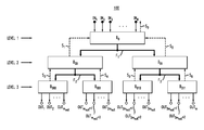
- FIG. 1 shows a block diagram of a packet router 100 according to one embodiment of the disclosure.
- packet router 100 can, for example, be used to implement an interleaver or a de-interleaver for error-correction-coding (ECC) processing in a disk storage system and/or a computer memory.
- ECC error-correction-coding
- Other (e.g., optical) implementations of packet router 100 are also contemplated.
- Packet router 100 has N input ports labeled IN 1 -IN N , where N is an integer greater than three. Packet router 100 further has M output ports labeled OUT 1 -OUT M , where M is a positive integer whose relationship with the number of input ports N and other structural parameters of the packet router is described in more detail below.
- packet router 100 is shown in FIG. 1 as having three hierarchical levels of buffer modules, with each buffer module being labeled by a capital letter “B” having a corresponding binary subscript.
- the subscript length depends on the level number. For example, the subscript corresponding to Level 1 is one bit long. The subscript corresponding to Level 2 is two bits long, etc.
- the number of levels (L) in packet router 100 can be two or greater than three.
- Level number provides an indicator of the relative position of a buffer-module level within the level hierarchy. More specifically, the greater the level number, the higher the position within the level hierarchy.
- Level 3 is a “higher” level than Level 2 or Level 1.
- Level 1 is a “lower” level than Level 2 or Level 3.
- Level 2 is a “higher” level than Level 1, but a lower level than Level 3.
- each buffer module B in the last (highest) level is connected to the same number (m out ) of output ports.
- M 2 L-1 m out (2)
- different buffer modules of the last level may be connected to different respective numbers of output ports OUT.
- each packet applied to an input port IN j of packet router 100 may have (i) a payload portion that carries W information bits and (ii) an address portion that carries up to L max address bits (also see Eq. (1)), with each of output ports OUT 1 -OUT M being assigned a unique address.
- input ports IN 1 -IN N of packet router 100 may receive a total maximum of N ⁇ W payload bits
- output ports OUT 1 -OUT M may output a total maximum of M ⁇ W payload bits.
- time slot refers to an internal time unit used in packet router 100 to synchronize and/or coordinate the operation of its various components.
- a time slot can be a cycle of a common clock, a time period occupied by a modulated symbol, etc.
- Each buffer module B of a lower (e.g., i-th) level in packet router 100 is connected to two corresponding buffer modules B in the immediately adjacent higher (e.g., (i+1)-th) level by a respective non-buffered interconnect fabric depicted in FIG. 1 by a respective branched solid line with two arrowheads.
- non-buffered means that, when a data packet is transmitted from a buffer module in one level of packet router 100 to a buffer module in the next level of the packet router, a packet transit time through the corresponding interconnect fabric is shorter than a single time-slot duration.
- interconnect fabric F 1 the interconnect fabric that connects the buffer modules of the first and second levels is labeled F 1 .
- the two interconnect fabrics that connect the buffer modules of the second and third levels are labeled F 2 and F 3 .
- interconnect fabrics F 1 , F 2 , and F 3 are analogous to one another and can be implemented as separate instances (copies) of the same physical device, circuit, or system.
- each of interconnect fabrics F 1 , F 2 , and F 3 can be implemented as a cross-connect switch.
- each of interconnect fabrics F 1 , F 2 , and F 3 can be implemented as a sorting network.
- Level 2 in packet router 100 is an intermediate level.
- interconnect fabric F 1 is an upstream interconnect fabric
- interconnect fabrics F 2 and F 3 are downstream interconnect fabrics. More specifically, for buffer module B 00 , interconnect fabrics F 1 and F 2 are the upstream and downstream interconnect fabrics, respectively. Similarly, for buffer module B 01 , interconnect fabrics F 1 and F 3 are the upstream and downstream interconnect fabrics, respectively.
- Each buffer module B in packet router 100 comprises an array of memory cells (not explicitly shown in FIG. 1 ) configured to operate as a packet queue. In each time slot, each buffer module B can enqueue up to a first corresponding number of packets and dequeue up to a second corresponding number of packets. For example, buffer module B 0 in Level 1 of packet router 100 can enqueue up to N packets in each time slot. Each of buffer modules B 000 , B 001 , B 010 , and B 011 in Level 3 of packet router 100 can dequeue up to m out packets in each time slot. The packet flow between different adjacent levels in packet router 100 depends on the throughput capacity of interconnect fabrics F 1 , F 2 , and F 3 .
- buffer module B 0 can dequeue up to n packets in each time slot.
- Each of buffer modules B 00 and B 01 in Level 2 of packet router 100 can (i) enqueue up to n packets in each time slot and (ii) dequeue up to n packets in each time slot.
- Each of buffer modules B 000 , B 001 , B 010 , and B 011 in Level 3 of packet router 100 can enqueue up to n packets in each time slot.
- each buffer module B may be able to enqueue/dequeue fewer than the above-indicated number(s) of packets, for example, when one or more of the following conditions apply to that buffer module: (i) buffer module B has an insufficient available storage space for receiving packets; (ii) one or both of the buffer modules to which buffer module B is directly connected in the higher level of packet router 100 has an insufficient available storage space for receiving packets from buffer module B; and (iii) two or more enqueued packets in buffer module B contend for the same output port.
- each buffer module B generates a respective backpressure signal S i , which is asserted when the buffer module is unable to accommodate a set of additional packets.
- backpressure signal S 0 is asserted when buffer module B 0 is unable to accommodate a set of additional packets directed to it via input ports IN 1 -IN N .
- Backpressure signal S 1 is asserted when buffer module B 00 is unable to accommodate a set of additional packets from buffer module B 0 .
- Backpressure signal S 2 is asserted when buffer module B 01 is unable to accommodate a set of additional packets from buffer module B 0 .
- Backpressure signal S 3 is asserted when buffer module B 000 is unable to accommodate additional a set of packets from buffer module B 00 , and so on.
- FIG. 2 shows a block diagram illustrating packet flow in buffer modules B 0 , B 00 , and B 01 in packet router 100 according to one embodiment of the disclosure.
- Buffer module B 0 has a chain of serially connected memory cells C 1 -C d0 that, in each time slot, can shift packets along the chain, from right to left, in a manner similar to that of a conventional unidirectional shift register. More specifically, when memory cell C i in buffer module B 0 is read out, the packet (if any) saved in memory cell C i+1 is shifted to memory cell C i ; the packet (if any) saved in memory cell C i+2 is shifted to memory cell C i+1 ; the packet (if any) saved in memory cell C i+3 is shifted to memory cell C i+2 , and so on. As indicated in FIG.
- each memory cell C i has a first partition configured to store payload bits (D) of a packet and a second partition configured to store a destination address (A) of that packet.
- address A i of each packet received by the packet router has been generated by an interleave-address generator (not explicitly shown in FIGS. 1 and 2 ) that generates addresses, as known in the art, in accordance with the operative interleave algorithm.
- Representative interleave-address generators that can be used for this purpose in conjunction with packet router 100 are disclosed, e.g., in U.S. Pat. Nos. 6,748,560, 6,507,629, and 6,321,311, all of which are incorporated herein by reference in their entirety.
- Buffer module B 0 further has an input interface 202 configured to write the received packets into the available memory cells of buffer module B 0 . More specifically, when backpressure signal S 0 is not asserted, input interface 202 writes a set of received packets into a corresponding set of empty memory cells that follow the last filled memory cell in the memory-cell chain of buffer module B 0 .
- memory cell C 5 represents the end of the packet queue in buffer module B 0 .
- input interface 202 receives three packets while the packets saved in memory cells C 1 -C 5 are not being moved. Then, the received packets will be written into memory cells C 6 -C 8 , respectively. After the write-in is completed, memory cell C 8 becomes the end of the packet queue in buffer module B 0 .
- Buffer module B 0 further has an output interface 204 configured to send the packets saved in memory cells C 1 and C 2 , via interconnect fabric F 1 , to buffer modules B 00 and B 01 . More specifically, if neither of backpressure signals S 1 and S 2 is asserted, then, depending on the destination addresses of the packets saved in memory cells C 1 and C 2 , output interface 204 may (i) send both packets to buffer module B 00 ; or (ii) send both packets to buffer module B 01 ; or (iii) send one packet to buffer module B 00 and one packet to buffer module B 01 .
- output interface 204 may (i) send both packets to buffer module B 00 or (ii) send only one packet to buffer module B 00 .
- output interface 204 may (i) send both packets to buffer module B 01 or (ii) send only one packet to buffer module B 01 .
- memory cells C 1 and C 2 represent the head of the packet queue in buffer module B 0 .
- the size of the head of the packet queue is directly related to the size of the corresponding output interface. More specifically, if the output interface is designed to read out data packets from any of the m left-most memory cells of the buffer module, then the head of the packet queue has a size of m.
- output interface 204 is configured to direct that packet, via interconnect fabric F 1 , to buffer module B 00 .
- the latter modifies the packet's destination address by removing the most significant bit (MSB) of the address, thereby shortening the length of the destination address by one bit.
- MSB most significant bit
- output interface 204 is configured to direct that packet, via interconnect fabric F 1 , to buffer module B 01 .
- the latter modifies the packet's destination address by removing the MSB of the address, thereby shortening the length of the destination address by one bit.
- This feature of packet router 100 may similarly be beneficial, e.g., because it enables buffer module B 01 to employ memory cells of smaller capacity than that in buffer module B 0 .
- the remaining packets located to the right of the read-out memory cell(s) in the head of the queue advance to the left by one or two positions so that the chain of the occupied memory cells is continuous and does not have any gaps within it. This advancement causes the enqueued packets to move into or closer to the head of the packet queue in buffer module B 0 .
- packets (A 1 ,D 1 ) and (A 2 ,D 2 ) are sent out, then (i) packet (A 3 ,D 3 ) advances from memory cell C 3 to memory cell C 1 ; (ii) packet (A 4 ,D 4 ) advances from memory cell C 4 to memory cell C 2 ; and (iii) packet (A 5 ,D 5 ) advances from memory cell C 5 to memory cell C 3 .
- input interface 202 also receives a set of new packets in that time slot, then those new packets are saved in a corresponding continuous set of memory cells in buffer module B 0 , starting with memory cell C 4 .
- packet (A 1 ,D 1 ) advances from memory cell C 2 to memory cell C 1 ;
- packet (A 3 ,D 3 ) advances from memory cell C 3 to memory cell C 2 ;
- packet (A 4 ,D 4 ) advances from memory cell C 4 to memory cell C 3 ;
- packet (A 5 ,D 5 ) advances from memory cell C 5 to memory cell C 4 .
- input interface 202 also receives a set of new packets in that time slot, then those new packets are saved in a corresponding continuous set of memory cells in buffer module B 0 , starting with memory cell C 5 .
- packet (A 2 ,D 2 ) if only packet (A 2 ,D 2 ) is sent out, then (i) packet (A 1 ,D 1 ) stays in memory cell C 1 ; (ii) packet (A 3 ,D 3 ) advances from memory cell C 3 to memory cell C 2 ; (iii) packet (A 4 ,D 4 ) advances from memory cell C 4 to memory cell C 3 ; and (iv) packet (A 5 ,D 5 ) advances from memory cell C 5 to memory cell C 4 . If input interface 202 also receives a set of new packets in that time slot, then those new packets are saved in a corresponding continuous set of memory cells in buffer module B 0 , starting with memory cell C 5 .
- Each of buffer modules B 00 and B 01 operates similar to buffer module B 0 . More specifically, each of buffer modules B 00 and B 01 has a respective chain of serially connected memory cells C 1 -C d1 that can shift packets in the chain from right to left. Note that, in various embodiments, d 1 (the number of memory cells in each of buffer modules B 00 and B 01 ) may be the same as or different from d0 (the number of memory cells in buffer module B 0 ). In some embodiments, the number of memory cells in buffer module B 00 may differ from the number of memory cells in buffer module B 01 . Each of buffer modules B 00 and B 01 further has a respective input interface 206 and a respective output interface 208 , each operating similar to input interface 202 and output interface 204 , respectively, of buffer module B 0 .
- each of input interfaces 202 and 206 is shown in FIG. 2 as being coupled to and configured to load received packets into any memory cell of the corresponding buffer module, alternative embodiments are also contemplated.
- an input interface analogous to any one of input interfaces 202 and 206 can be coupled to and configured to load received packets into a specified number (e.g., two or any other number smaller than d i ) of memory cells located at the (“right”) end of the corresponding buffer module.
- the packets loaded in at the “right” end of the buffer module are then properly moved along the chain of memory cells toward the “left” end of the buffer module to remove any possible gaps in the queue of packets therein.
- the packet-router architecture exemplified by packet router 100 has an advantageous characteristic of enabling the packet-router designer to realize any desired trade-off between the router's performance characteristics and the router's implementation complexity.
- the fact that buffer modules in different levels of the packet router have the same parameterized structure (although the use of different level-specific parameters is still possible) significantly streamlines the design process in general and the RTL (register-transfer level) models of buffer modules in particular.
- the packet-router designer has remarkable flexibility in choosing a suitable implementation of interconnect fabrics for connecting the appropriate buffer modules in adjacent packet-router levels to one another. For example, by limiting the number of packets that an interconnect fabric can transmit per time slot to a relatively small value, the relative implementation complexity of the interconnect fabrics can be in a low-to-moderate range.
- a packet router it is useful in general to configure a packet router to remove the MSB of the (present) routing address while moving packets to progressively higher levels within the router. As already indicated above, this feature may be beneficial because it enables the buffer modules in the higher levels of the packet router to have progressively smaller space for the storage of destination addresses.
- an act of “transmitting” a packet is implemented by not moving the payload of the packet from its physical storage location, but rather by manipulating pointers identifying that physical storage location, e.g., by moving the pointers through an interconnect structure.
- a packet router can be implemented using a hierarchy of buffer levels in which (i) an interconnect fabric analogous to any one of interconnect fabrics F 1 , F 2 , and F 3 is configured to connect one buffer module of a lower level to four, eight, or sixteen, etc., buffer modules of the next higher level and (iii) two, three, or four MSBs, respectively, are used to route packets from said lower level to said next higher level.
- an interconnect fabric analogous to any one of interconnect fabrics F 1 , F 2 , and F 3 is configured to connect one buffer module of a lower level to four, eight, or sixteen, etc., buffer modules of the next higher level and (iii) two, three, or four MSBs, respectively, are used to route packets from said lower level to said next higher level.
- terminal memory cell and “terminal position” refer to a memory cell that is analogous to memory cell C 1 in any of buffer modules B 0 , B 00 , and B 01 shown in FIG. 2 .
- memory cell C 1 is characterized in that (i) it represents the most “advanced” position in the packet queue and (ii) a packet stored in memory cell C 1 is normally removed from it only through the corresponding output interface, such as one of output interfaces 204 or 208 , rather than by being shifted to another memory cell within the same buffer module.
- a packet router may include: an input buffer module configured to receive packets from a set of input ports; a set of output buffer modules, each configured to direct packets stored therein to a respective set of output ports; and one or more interconnect fabrics configured to transport packets between the input buffer module and the set of the output buffer modules.
- Each of said one or more interconnect fabrics is disposed between a respective first buffer module, a respective second buffer module, and a respective third buffer module and is configured to transport packets from said respective first buffer module to said respective second and third buffer modules.
- Said respective first buffer module is configured to: enqueue packets at an end of a queue therein in an order of their arrival to said respective first buffer module; dequeue packets from a head of the queue; and advance packets toward the head of the queue when the first buffer module dequeues one or more packets from the head of the queue and transmits the one or more dequeued packets, via the interconnect fabric, to at least one of said respective second buffer module and said respective third buffer module.
- the packet router comprises a first interconnect fabric configured to transport packets from the input buffer module directly to a first output buffer module and a second output buffer module in said set of the output buffer modules.
- the packet router further includes a plurality of intermediate buffer modules, wherein an intermediate buffer module of said plurality is configured to: receive, via a respective upstream interconnect fabric, packets from a buffer module in a next lower level; and transmit, via a respective downstream interconnect fabric, packets to a respective pair of buffer modules in a next higher level.
- the head of the queue includes two or more positions; and said respective first buffer module is configured to dequeue packets from any position within the head of the queue.
- said respective first buffer module is configured to dequeue a packet currently located in a non-terminal position in the head of the queue before before dequeueing a packet currently located in a terminal position in the head of the queue.
- said respective first buffer module is configured to advance packets in the queue to fill one or more gaps formed by the dequeued packets and without forming other gaps in the queue.
- said respective first buffer module is configured to dequeue, from the head of the queue, two or more packets per time slot.
- each enqueued packet has a destination address; and said respective first buffer module is configured to: transmit an enqueued packet to said respective second buffer module if the most significant bit (MSB) in the packet's destination address has a first binary value; and transmit the enqueued packet to said respective third buffer module if the MSB in the packet's destination address has a second binary value different from the first binary value.
- MSB most significant bit
- each of said respective second buffer module and said respective third buffer module is configured to: enqueue received packets at an end of a respective queue therein in an order of their arrival to the buffer module; and shorten the received packet's destination address by removing the MSB.
- each of said respective second buffer module and said respective third buffer module is configured to: enqueue received packets at an end of a respective queue therein in an order of their arrival to the buffer module; and dequeue enqueued packets from a head of said respective queue; and advance enqueued packets toward the head of said respective queue when the buffer module dequeues one or more of the enqueued packets from the head of said respective queue.
- the packet router further includes: a respective first signal path for transmitting a first backpressure signal from the respective second buffer module to the respective first buffer module, said first backpressure signal being asserted when the respective second buffer module has insufficient space for receiving packets from the respective first buffer module; and a respective second signal path for transmitting a second backpressure signal from the respective third buffer module to the respective first buffer module, said second backpressure signal being asserted when the respective third buffer module has insufficient space for receiving packets from the respective first buffer module.
- the respective first buffer module when the first backpressure signal is asserted, is configured to transmit packets, via the interconnect fabric, to the respective third buffer module, but not to the respective second buffer module.
- the respective first buffer module is configured to transmit, via the interconnect fabric, to the respective third buffer module two or more packets per time slot.
- the packet router is configured to implement an interleaver or a de-interleaver.
- said interleaver or de-interleaver is part of a circuit configured to perform error-correction-coding processing in a data-storage device.
- At least one of said one or more interconnect fabrics is configured to transport packets therethrough using an optical carrier wave.
- a packet router may include: a plurality of buffer modules arranged into a plurality of hierarchical buffer levels; and one or more interconnect fabrics, each disposed between a respective first buffer module, a respective second buffer module, and a respective third buffer module and configured to transport packets from said respective first buffer module to said respective second and third buffer modules.
- a higher hierarchical buffer level has more buffer modules than a corresponding lower hierarchical buffer level.
- said respective second buffer module and said respective third buffer module belong to a common hierarchical buffer level; and said respective first buffer module belongs to a hierarchical buffer level that is one level lower than said common hierarchical buffer level.
- each of said respective first, second, and third buffer modules is configured to: enqueue packets at an end of a respective queue therein in an order of their arrival to said respective buffer module; dequeue packets from a head of the respective queue; and advance packets toward the head of the respective queue when the respective buffer module dequeues one or more packets from the head of the respective queue and transmits the one or more dequeued packets to at least one buffer module in a next higher hierarchical buffer level or to a respective set of output ports connected to the buffer module.
- a packet-routing method comprises transporting packets using a plurality of buffer modules arranged into a plurality of hierarchical buffer levels, wherein: a higher hierarchical buffer level has more buffer modules than a corresponding lower hierarchical buffer level; and said transporting comprises: in each set of three buffer modules that comprises a respective first buffer module, a respective second buffer module, and a respective third buffer module, enqueueing a respective subset of the packets in a packet queue at said respective first buffer module; transmitting a packet of said respective subset of the packets, through a respective interconnect fabric, to said respective second buffer module or said respective third buffer module, when said packet reaches a head of the packet queue in said respective first buffer module; and enqueueing respective received packets in respective packet queues at said respective second buffer module and said respective third buffer module, wherein: said respective second buffer module and said respective third buffer module belong to a common hierarchical buffer level; and said respective first buffer module belongs to a hierarchical buffer level
- the disclosed embodiments may be implemented as circuit-based processes, including possible implementation on a single integrated circuit.
- each numerical value and range should be interpreted as being approximate as if the word “about” or “approximately” preceded the value of the value or range.
- figure numbers and/or figure reference labels in the claims is intended to identify one or more possible embodiments of the claimed subject matter in order to facilitate the interpretation of the claims. Such use is not to be construed as necessarily limiting the scope of those claims to the embodiments shown in the corresponding figures.
- Couple refers to any manner known in the art or later developed in which energy is allowed to be transferred between two or more elements, and the interposition of one or more additional elements is contemplated, although not required. Conversely, the terms “directly coupled,” “directly connected,” etc., imply the absence of such additional elements.
- program storage devices e.g., digital data storage media, which are machine or computer readable and encode machine-executable or computer-executable programs of instructions where said instructions perform some or all of the steps of methods described herein.
- the program storage devices may be, e.g., digital memories, magnetic storage media, such as magnetic disks or tapes, hard drives, or optically readable digital data storage media.
- processors may be provided through the use of dedicated hardware as well as hardware capable of executing software in association with appropriate software.
- the functions may be provided by a single dedicated processor, by a single shared processor, or by a plurality of individual processors, some of which may be shared.
- explicit use of the term “processor” or “controller” should not be construed to refer exclusively to hardware capable of executing software, and may implicitly include, without limitation, digital signal processor (DSP) hardware, network processor, application specific integrated circuit (ASIC), field programmable gate array (FPGA), read only memory (ROM) for storing software, random access memory (RAM), and non volatile storage.
- DSP digital signal processor
- ASIC application specific integrated circuit
- FPGA field programmable gate array
- ROM read only memory
- RAM random access memory
- non volatile storage Other hardware, conventional and/or custom, may also be included.
Abstract
Description
L max=┌ log2 M┐ (1)
where the ceiling brackets denote the ceiling function (that rounds up to the nearest integer).
M=2L-1 m out (2)
For example, in the embodiment shown in
Claims (14)
Applications Claiming Priority (2)
| Application Number | Priority Date | Filing Date | Title |
|---|---|---|---|
| RU2012130778/08A RU2012130778A (en) | 2012-07-18 | 2012-07-18 | PACKAGE ROUTER WITH HIERARCHIC BUFFER STRUCTURE |
| RU2012130778 | 2012-07-18 |
Publications (2)
| Publication Number | Publication Date |
|---|---|
| US20140023085A1 US20140023085A1 (en) | 2014-01-23 |
| US8923315B2 true US8923315B2 (en) | 2014-12-30 |
Family
ID=49946511
Family Applications (1)
| Application Number | Title | Priority Date | Filing Date |
|---|---|---|---|
| US13/777,629 Active 2033-08-05 US8923315B2 (en) | 2012-07-18 | 2013-02-26 | Packet router having a hierarchical buffer structure |
Country Status (2)
| Country | Link |
|---|---|
| US (1) | US8923315B2 (en) |
| RU (1) | RU2012130778A (en) |
Families Citing this family (3)
| Publication number | Priority date | Publication date | Assignee | Title |
|---|---|---|---|---|
| US10425371B2 (en) * | 2013-03-15 | 2019-09-24 | Trane International Inc. | Method for fragmented messaging between network devices |
| US10439952B1 (en) * | 2016-07-07 | 2019-10-08 | Cisco Technology, Inc. | Providing source fairness on congested queues using random noise |
| KR102165864B1 (en) * | 2019-07-22 | 2020-10-14 | 성균관대학교산학협력단 | Methods and apparatuses for packet scheduling for software defined networking in edge computing environment |
Citations (19)
| Publication number | Priority date | Publication date | Assignee | Title |
|---|---|---|---|---|
| US6321311B1 (en) | 1996-10-02 | 2001-11-20 | Samsung Electronics Co., Ltd. | Interleave read address generator |
| US20020012356A1 (en) * | 2000-06-16 | 2002-01-31 | Li Shuo-Yen Robert | Packet switch with one-stop buffer in memory with massive parallel access |
| US6507629B1 (en) | 1998-04-07 | 2003-01-14 | Sony Corporation | Address generator, interleave unit, deinterleave unit, and transmission unit |
| US20030112817A1 (en) * | 2001-11-16 | 2003-06-19 | Woo Leon K. | Methods and apparatus for differentiated services over a packet-based network |
| US6813445B2 (en) | 1997-02-24 | 2004-11-02 | Hitachi, Ltd. | Optical crossconnect apparatus and optical transmission system |
| US6819630B1 (en) | 2002-09-20 | 2004-11-16 | The United States Of America As Represented By The Secretary Of The Navy | Iterative decision feedback adaptive equalizer |
| US7228483B2 (en) | 2003-06-09 | 2007-06-05 | Matsushita Electric Industrial Co., Ltd. | Turbo decoding device |
| US7397808B2 (en) | 2002-10-31 | 2008-07-08 | Seoul National University Industry Foundation | Parallel switching architecture for multiple input/output |
| US7530011B2 (en) | 2002-06-05 | 2009-05-05 | Fujitsu Limited | Turbo decoding method and turbo decoding apparatus |
| US7603509B1 (en) | 2008-02-06 | 2009-10-13 | Adaptive Design Solutions, Inc. | Crossbar switch with grouped inputs and outputs |
| US7631243B2 (en) | 2005-03-09 | 2009-12-08 | Harris Corporation | System and method for communicating data using iterative equalizing and decoding and recursive inner code |
| US7734989B2 (en) | 2003-12-11 | 2010-06-08 | Freescale Semiconductor, Inc. | Multi-standard turbo interleaver using tables |
| US7917830B2 (en) | 2007-09-28 | 2011-03-29 | Via Technologies, Inc. | Turbo decoder and iteration stopping method thereof |
| US7994818B2 (en) | 2007-06-20 | 2011-08-09 | Agate Logic (Beijing), Inc. | Programmable interconnect network for logic array |
| US8006024B2 (en) | 2001-10-17 | 2011-08-23 | Jinsalas Solutions, Llc | Multi-port system and method for routing a data element within an interconnection fabric |
| US8089959B2 (en) | 2006-05-30 | 2012-01-03 | Ted Henryk Szymanski | Method and apparatus to schedule packets through a crossbar switch with delay guarantees |
| US8107779B2 (en) | 2007-02-26 | 2012-01-31 | Fiberzone Networks Ltd. | Optical crossbar switch |
| US8171186B1 (en) | 2011-01-31 | 2012-05-01 | Texas Instruments Incorporated | On-chip interconnect fabric |
| US20130125097A1 (en) * | 2011-11-15 | 2013-05-16 | Global Supercomputing Corporation | Method and system for converting a single-threaded software program into an application-specific supercomputer |
-
2012
- 2012-07-18 RU RU2012130778/08A patent/RU2012130778A/en not_active Application Discontinuation
-
2013
- 2013-02-26 US US13/777,629 patent/US8923315B2/en active Active
Patent Citations (20)
| Publication number | Priority date | Publication date | Assignee | Title |
|---|---|---|---|---|
| US6321311B1 (en) | 1996-10-02 | 2001-11-20 | Samsung Electronics Co., Ltd. | Interleave read address generator |
| US6813445B2 (en) | 1997-02-24 | 2004-11-02 | Hitachi, Ltd. | Optical crossconnect apparatus and optical transmission system |
| US6507629B1 (en) | 1998-04-07 | 2003-01-14 | Sony Corporation | Address generator, interleave unit, deinterleave unit, and transmission unit |
| US6748560B2 (en) | 1998-04-07 | 2004-06-08 | Sony Corporation | Address generator, interleave unit, deinterleaver unit, and transmission unit |
| US20020012356A1 (en) * | 2000-06-16 | 2002-01-31 | Li Shuo-Yen Robert | Packet switch with one-stop buffer in memory with massive parallel access |
| US8006024B2 (en) | 2001-10-17 | 2011-08-23 | Jinsalas Solutions, Llc | Multi-port system and method for routing a data element within an interconnection fabric |
| US20030112817A1 (en) * | 2001-11-16 | 2003-06-19 | Woo Leon K. | Methods and apparatus for differentiated services over a packet-based network |
| US7530011B2 (en) | 2002-06-05 | 2009-05-05 | Fujitsu Limited | Turbo decoding method and turbo decoding apparatus |
| US6819630B1 (en) | 2002-09-20 | 2004-11-16 | The United States Of America As Represented By The Secretary Of The Navy | Iterative decision feedback adaptive equalizer |
| US7397808B2 (en) | 2002-10-31 | 2008-07-08 | Seoul National University Industry Foundation | Parallel switching architecture for multiple input/output |
| US7228483B2 (en) | 2003-06-09 | 2007-06-05 | Matsushita Electric Industrial Co., Ltd. | Turbo decoding device |
| US7734989B2 (en) | 2003-12-11 | 2010-06-08 | Freescale Semiconductor, Inc. | Multi-standard turbo interleaver using tables |
| US7631243B2 (en) | 2005-03-09 | 2009-12-08 | Harris Corporation | System and method for communicating data using iterative equalizing and decoding and recursive inner code |
| US8089959B2 (en) | 2006-05-30 | 2012-01-03 | Ted Henryk Szymanski | Method and apparatus to schedule packets through a crossbar switch with delay guarantees |
| US8107779B2 (en) | 2007-02-26 | 2012-01-31 | Fiberzone Networks Ltd. | Optical crossbar switch |
| US7994818B2 (en) | 2007-06-20 | 2011-08-09 | Agate Logic (Beijing), Inc. | Programmable interconnect network for logic array |
| US7917830B2 (en) | 2007-09-28 | 2011-03-29 | Via Technologies, Inc. | Turbo decoder and iteration stopping method thereof |
| US7603509B1 (en) | 2008-02-06 | 2009-10-13 | Adaptive Design Solutions, Inc. | Crossbar switch with grouped inputs and outputs |
| US8171186B1 (en) | 2011-01-31 | 2012-05-01 | Texas Instruments Incorporated | On-chip interconnect fabric |
| US20130125097A1 (en) * | 2011-11-15 | 2013-05-16 | Global Supercomputing Corporation | Method and system for converting a single-threaded software program into an application-specific supercomputer |
Non-Patent Citations (6)
| Title |
|---|
| Batcher, K. E., "Sorting Networks and their Applications," Proceeding AFIPS '68 (Spring) Proceedings of the Apr. 30-May 2, 1968, Spring Joint Computer Conference, pp. 307-314. |
| Briffa, Johann, "Interleavers for Turbo Codes," Master of Philosophy Dissertation, Dept. of Communications and Computer Engineering, University of Malta, Oct. 1999 (130 pages). |
| Devault, Michel, et al., "The "Prelude" ATD Experiment: Assessments and Future Prospects," IEEE Journal on Selected Areas in Communications, vol. 6, No. 9, Dec. 1988, pp. 1528-1537. |
| Hui, Joseph Y., et al., "A Broadband Packet Switch for Integrated Transport," IEEE Journal on Selected Areas in Communications, vol. SAC-5, No. 8, Oct. 1987, pp. 1264-1273. |
| Tüchler, Michael, et al., "Turbo Equalization: Principles and New Results," IEEE Transactions on Communications, vol. 50, No. 5, May 2002, pp. |
| Yeh, Yu-Shuan, et al., "The Knockout Switch: A Simple, Modular Architecture for High-Performance Packet Switching," IEEE Journal on Selected Areas in Communications, vol. SAC-5, No. 8, Oct. 1987 pp. 1274-1280. |
Also Published As
| Publication number | Publication date |
|---|---|
| RU2012130778A (en) | 2014-01-27 |
| US20140023085A1 (en) | 2014-01-23 |
Similar Documents
| Publication | Publication Date | Title |
|---|---|---|
| EP1839166B1 (en) | Shared-memory switch fabric architecture | |
| JP5863076B2 (en) | Method, apparatus, and system for reconstructing and reordering packets | |
| TWI390913B (en) | Apparatus, method, and machine-readable storage medium for transferring data between data modules using a buffered crossbar switch system | |
| EP2239895B1 (en) | Space-Space-Memory (SSM) Clos-Network Packet Switch | |
| EP1045558B1 (en) | Very wide memory TDM switching system | |
| US7546399B2 (en) | Store and forward device utilizing cache to store status information for active queues | |
| US8243737B2 (en) | High speed packet FIFO input buffers for switch fabric with speedup and retransmit | |
| CA2297836C (en) | Multi-port internally cached drams | |
| US7439763B1 (en) | Scalable shared network memory switch for an FPGA | |
| WO2006082923A1 (en) | Parallel interleaver, parallel deinterleaver, and interleave method | |
| US7991926B1 (en) | Scalable memory architecture for high speed crossbars using variable cell or packet length | |
| EP0848891A1 (en) | Switching device, method and apparatus | |
| CN110247970B (en) | Dynamic sharing buffer device for interconnected chips | |
| US8923315B2 (en) | Packet router having a hierarchical buffer structure | |
| JP5332430B2 (en) | Shared memory system | |
| US7568074B1 (en) | Time based data storage for shared network memory switch | |
| CN111611180A (en) | Dynamic shared buffer area supporting multiple protocols | |
| JPH0863954A (en) | First-in first-out (fifo) memory | |
| US6954466B1 (en) | Link-layer receiver | |
| US7111093B2 (en) | Ping-pong buffer system having a buffer to store a subset of data from a data source | |
| US7730276B1 (en) | Striping of data into memory of a network data switch to prevent read and write collisions | |
| US5546393A (en) | Asynchronous transfer mode data cell routing device for a reverse omega network | |
| US9544229B2 (en) | Packet processing apparatus and packet processing method | |
| US7996604B1 (en) | Class queue for network data switch to identify data memory locations by arrival time | |
| Simos et al. | Building an FoC using large, buffered crossbar cores |
Legal Events
| Date | Code | Title | Description |
|---|---|---|---|
| AS | Assignment |
Owner name: LSI CORPORATION, CALIFORNIA Free format text: ASSIGNMENT OF ASSIGNORS INTEREST;ASSIGNORS:ALISEYCHIK, PAVEL ALEKSANDROVICH;GASANOV, ELYAR ELDAROVICH;NEZNANOV, ILYA VLADIMIROVICH;AND OTHERS;REEL/FRAME:029879/0768 Effective date: 20120807 |
|
| AS | Assignment |
Owner name: DEUTSCHE BANK AG NEW YORK BRANCH, AS COLLATERAL AG Free format text: PATENT SECURITY AGREEMENT;ASSIGNORS:LSI CORPORATION;AGERE SYSTEMS LLC;REEL/FRAME:032856/0031 Effective date: 20140506 |
|
| STCF | Information on status: patent grant |
Free format text: PATENTED CASE |
|
| AS | Assignment |
Owner name: AVAGO TECHNOLOGIES GENERAL IP (SINGAPORE) PTE. LTD Free format text: ASSIGNMENT OF ASSIGNORS INTEREST;ASSIGNOR:LSI CORPORATION;REEL/FRAME:035390/0388 Effective date: 20140814 |
|
| AS | Assignment |
Owner name: LSI CORPORATION, CALIFORNIA Free format text: TERMINATION AND RELEASE OF SECURITY INTEREST IN PATENT RIGHTS (RELEASES RF 032856-0031);ASSIGNOR:DEUTSCHE BANK AG NEW YORK BRANCH, AS COLLATERAL AGENT;REEL/FRAME:037684/0039 Effective date: 20160201 Owner name: AGERE SYSTEMS LLC, PENNSYLVANIA Free format text: TERMINATION AND RELEASE OF SECURITY INTEREST IN PATENT RIGHTS (RELEASES RF 032856-0031);ASSIGNOR:DEUTSCHE BANK AG NEW YORK BRANCH, AS COLLATERAL AGENT;REEL/FRAME:037684/0039 Effective date: 20160201 |
|
| AS | Assignment |
Owner name: BANK OF AMERICA, N.A., AS COLLATERAL AGENT, NORTH CAROLINA Free format text: PATENT SECURITY AGREEMENT;ASSIGNOR:AVAGO TECHNOLOGIES GENERAL IP (SINGAPORE) PTE. LTD.;REEL/FRAME:037808/0001 Effective date: 20160201 Owner name: BANK OF AMERICA, N.A., AS COLLATERAL AGENT, NORTH Free format text: PATENT SECURITY AGREEMENT;ASSIGNOR:AVAGO TECHNOLOGIES GENERAL IP (SINGAPORE) PTE. LTD.;REEL/FRAME:037808/0001 Effective date: 20160201 |
|
| AS | Assignment |
Owner name: AVAGO TECHNOLOGIES GENERAL IP (SINGAPORE) PTE. LTD., SINGAPORE Free format text: TERMINATION AND RELEASE OF SECURITY INTEREST IN PATENTS;ASSIGNOR:BANK OF AMERICA, N.A., AS COLLATERAL AGENT;REEL/FRAME:041710/0001 Effective date: 20170119 Owner name: AVAGO TECHNOLOGIES GENERAL IP (SINGAPORE) PTE. LTD Free format text: TERMINATION AND RELEASE OF SECURITY INTEREST IN PATENTS;ASSIGNOR:BANK OF AMERICA, N.A., AS COLLATERAL AGENT;REEL/FRAME:041710/0001 Effective date: 20170119 |
|
| MAFP | Maintenance fee payment |
Free format text: PAYMENT OF MAINTENANCE FEE, 4TH YEAR, LARGE ENTITY (ORIGINAL EVENT CODE: M1551) Year of fee payment: 4 |
|
| AS | Assignment |
Owner name: AVAGO TECHNOLOGIES INTERNATIONAL SALES PTE. LIMITE Free format text: MERGER;ASSIGNOR:AVAGO TECHNOLOGIES GENERAL IP (SINGAPORE) PTE. LTD.;REEL/FRAME:047229/0408 Effective date: 20180509 |
|
| AS | Assignment |
Owner name: AVAGO TECHNOLOGIES INTERNATIONAL SALES PTE. LIMITE Free format text: CORRECTIVE ASSIGNMENT TO CORRECT THE EFFECTIVE DATE PREVIOUSLY RECORDED ON REEL 047229 FRAME 0408. ASSIGNOR(S) HEREBY CONFIRMS THE THE EFFECTIVE DATE IS 09/05/2018;ASSIGNOR:AVAGO TECHNOLOGIES GENERAL IP (SINGAPORE) PTE. LTD.;REEL/FRAME:047349/0001 Effective date: 20180905 |
|
| AS | Assignment |
Owner name: AVAGO TECHNOLOGIES INTERNATIONAL SALES PTE. LIMITE Free format text: CORRECTIVE ASSIGNMENT TO CORRECT THE PATENT NUMBER 9,385,856 TO 9,385,756 PREVIOUSLY RECORDED AT REEL: 47349 FRAME: 001. ASSIGNOR(S) HEREBY CONFIRMS THE MERGER;ASSIGNOR:AVAGO TECHNOLOGIES GENERAL IP (SINGAPORE) PTE. LTD.;REEL/FRAME:051144/0648 Effective date: 20180905 |
|
| MAFP | Maintenance fee payment |
Free format text: PAYMENT OF MAINTENANCE FEE, 8TH YEAR, LARGE ENTITY (ORIGINAL EVENT CODE: M1552); ENTITY STATUS OF PATENT OWNER: LARGE ENTITY Year of fee payment: 8 |