US8920441B2 - Methods of meniscus repair - Google Patents
Methods of meniscus repair Download PDFInfo
- Publication number
- US8920441B2 US8920441B2 US13/462,760 US201213462760A US8920441B2 US 8920441 B2 US8920441 B2 US 8920441B2 US 201213462760 A US201213462760 A US 201213462760A US 8920441 B2 US8920441 B2 US 8920441B2
- Authority
- US
- United States
- Prior art keywords
- arm
- suture
- tissue
- tissue penetrator
- shuttle
- Prior art date
- Legal status (The legal status is an assumption and is not a legal conclusion. Google has not performed a legal analysis and makes no representation as to the accuracy of the status listed.)
- Active
Links
Images


Classifications
-
- A—HUMAN NECESSITIES
- A61—MEDICAL OR VETERINARY SCIENCE; HYGIENE
- A61B—DIAGNOSIS; SURGERY; IDENTIFICATION
- A61B17/00—Surgical instruments, devices or methods, e.g. tourniquets
- A61B17/04—Surgical instruments, devices or methods, e.g. tourniquets for suturing wounds; Holders or packages for needles or suture materials
- A61B17/0401—Suture anchors, buttons or pledgets, i.e. means for attaching sutures to bone, cartilage or soft tissue; Instruments for applying or removing suture anchors
-
- A—HUMAN NECESSITIES
- A61—MEDICAL OR VETERINARY SCIENCE; HYGIENE
- A61B—DIAGNOSIS; SURGERY; IDENTIFICATION
- A61B17/00—Surgical instruments, devices or methods, e.g. tourniquets
- A61B17/04—Surgical instruments, devices or methods, e.g. tourniquets for suturing wounds; Holders or packages for needles or suture materials
- A61B17/0482—Needle or suture guides
-
- A—HUMAN NECESSITIES
- A61—MEDICAL OR VETERINARY SCIENCE; HYGIENE
- A61B—DIAGNOSIS; SURGERY; IDENTIFICATION
- A61B17/00—Surgical instruments, devices or methods, e.g. tourniquets
- A61B17/04—Surgical instruments, devices or methods, e.g. tourniquets for suturing wounds; Holders or packages for needles or suture materials
- A61B17/0483—Hand-held instruments for holding sutures
-
- A—HUMAN NECESSITIES
- A61—MEDICAL OR VETERINARY SCIENCE; HYGIENE
- A61B—DIAGNOSIS; SURGERY; IDENTIFICATION
- A61B17/00—Surgical instruments, devices or methods, e.g. tourniquets
- A61B17/04—Surgical instruments, devices or methods, e.g. tourniquets for suturing wounds; Holders or packages for needles or suture materials
- A61B17/0485—Devices or means, e.g. loops, for capturing the suture thread and threading it through an opening of a suturing instrument or needle eyelet
-
- A—HUMAN NECESSITIES
- A61—MEDICAL OR VETERINARY SCIENCE; HYGIENE
- A61B—DIAGNOSIS; SURGERY; IDENTIFICATION
- A61B17/00—Surgical instruments, devices or methods, e.g. tourniquets
- A61B17/04—Surgical instruments, devices or methods, e.g. tourniquets for suturing wounds; Holders or packages for needles or suture materials
- A61B17/06—Needles ; Sutures; Needle-suture combinations; Holders or packages for needles or suture materials
- A61B17/06166—Sutures
-
- A—HUMAN NECESSITIES
- A61—MEDICAL OR VETERINARY SCIENCE; HYGIENE
- A61B—DIAGNOSIS; SURGERY; IDENTIFICATION
- A61B17/00—Surgical instruments, devices or methods, e.g. tourniquets
- A61B17/04—Surgical instruments, devices or methods, e.g. tourniquets for suturing wounds; Holders or packages for needles or suture materials
- A61B17/0469—Suturing instruments for use in minimally invasive surgery, e.g. endoscopic surgery
- A61B2017/0472—Multiple-needled, e.g. double-needled, instruments
-
- A—HUMAN NECESSITIES
- A61—MEDICAL OR VETERINARY SCIENCE; HYGIENE
- A61B—DIAGNOSIS; SURGERY; IDENTIFICATION
- A61B17/00—Surgical instruments, devices or methods, e.g. tourniquets
- A61B17/04—Surgical instruments, devices or methods, e.g. tourniquets for suturing wounds; Holders or packages for needles or suture materials
- A61B17/06—Needles ; Sutures; Needle-suture combinations; Holders or packages for needles or suture materials
- A61B17/06004—Means for attaching suture to needle
- A61B2017/06042—Means for attaching suture to needle located close to needle tip
-
- A—HUMAN NECESSITIES
- A61—MEDICAL OR VETERINARY SCIENCE; HYGIENE
- A61B—DIAGNOSIS; SURGERY; IDENTIFICATION
- A61B17/00—Surgical instruments, devices or methods, e.g. tourniquets
- A61B17/04—Surgical instruments, devices or methods, e.g. tourniquets for suturing wounds; Holders or packages for needles or suture materials
- A61B17/06—Needles ; Sutures; Needle-suture combinations; Holders or packages for needles or suture materials
- A61B2017/06052—Needle-suture combinations in which a suture is extending inside a hollow tubular needle, e.g. over the entire length of the needle
Definitions
- U.S. patent application Ser. No. 13/090,089 is also a continuation-in-part of U.S. patent application Ser. No. 12/291,159, filed on Nov. 5, 2008, titled “SUTURE PASSING INSTRUMENT AND METHOD,” now Publication No. US-2010-0331863-A2, which claims the benefit of the filing dates of U.S. Provisional Patent Application Nos. 60/985,543, filed on Nov. 5, 2007; 60/985,556, filed on Nov. 5, 2007; 61/013,989, filed on Dec. 14, 2007; 61/013,994, filed on Dec. 14, 2007; 61/014,728, filed on Dec. 18, 2007; 61/013,999, filed on Dec. 14, 2007; 61/014,003, filed on Dec. 14, 2007; 61/014,012, filed on Dec. 14, 2007; 61/042,678, filed on Apr. 4, 2008; and 61/127,658, filed on May 14, 2008.
- This invention relates to surgical stitching devices by which a stitch or continuous stitches may be made during surgery.
- Suturing instruments for assisting a medical practitioner in placing stitches during surgical procedures are particularly helpful in surgical procedures requiring the placement of secure and accurate sutures in difficult to access regions of the body.
- Instruments and methods for suturing remotely are especially important in minimally invasive surgical procedures such as laparoscopic and endoscopic procedures.
- suturing instruments may also allow the efficient manipulation of very small needles and the formation of small and precise sutures.
- the meniscus is a C-shaped piece of fibrocartilage which is located at the peripheral aspect of the joint (e.g., the knee).
- the central 2 ⁇ 3 rds of the meniscus has a limited blood supply while the peripheral 1 ⁇ 3 rd typically has an excellent blood supply.
- Young patients typically tear their menisci from traumatic events while degenerative tears are common in older patients as the menisci become increasingly brittle with age.
- the torn piece begins to move in an abnormal fashion inside the joint, which may lead to pain and loss of function of the joint.
- Arthroscopy typically involves inserting a fiberoptic telescope that is about the size of a pencil into the joint through an incision that is approximately 1 ⁇ 8 inch long. Fluid may then be inserted into the joint to distend the joint and to allow for the visualization of the structures within that joint. Then, using miniature instruments which may be as small as 1/10 of an inch, the structures are examined and the surgery is performed.
- FIGS. 59A-B illustrate the anatomy of the meniscus in the context of a knee joint.
- the capsule region (the outer edge region of the meniscus) is vascularized.
- a typical meniscus has a flattened (“bottom”) and a concave top, and the outer cross-sectional shape is somewhat triangular.
- the outer edge of the meniscus transitions into the capsule.
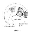
- FIG. 61 illustrates the various fibers forming a meniscus. As illustrated in FIG. 61 , there are circumferential fibers extending along the curved length of the meniscus, as well as radial fibers, and more randomly distributed mesh network fibers.
- FIGS. 62A-62E illustrate various tear patterns or injuries to a meniscus. Tears may be vertical/longitudinal ( FIG. 62A ), Oblique ( FIG. 62B ), Degenerative ( FIG. 62C ), including radially degenerative, Transverse or radial ( FIG. 62D ) and Horizontal ( FIG. 62E ). Most prior art devices for suturing or repairing the meniscus are only capable of reliably repairing vertical/longitudinal tears. Such devices are not typically recommended for repair of radial tears, particularly not arthroscopically/minimally invasively. FIGS.
- FIG. 63A-63C illustrate sutures placed with prior art devices to repair (via suturing) a torn meniscus (showing a longitudinal tear).
- FIG. 63A illustrates the results of a repair by a Smith&Nephew “Fast-T-Fix” device (comparable to a repair by a Biomet MaxFire device).
- FIG. 63B illustrates a Cayanne “CrossFix” device
- FIG. 63C illustrates a repair using an Arthrex meniscal “Viper” device.
- FIGS. 63A-62C the devices affecting these repairs require projection through the meniscus and substantially into the capsule region outside of the meniscus, which could potentially damage the nearby major nerves and large blood vessels.
- the prior art devices such as those placing the sutures illustrated in FIG. 63A-63C , typically place horizontal mattress suture patterns rather than vertical mattress suture patterns because vertical patterns are considerably more difficult for surgeons to place when using these devices. Vertical mattress patterns would have improved pull through strength because of the aforementioned predominance of circumferential collagen fibers found within the meniscus structure.
- the devices forming the suture patterns illustrated in FIG. 63A-63C are only capable of point fixation; that is they cannot compress the tears uniformly across the torn surface.
- such prior art devices are designed for repairing peripheral vertical meniscus tears (torn from the superior surface to the inferior surface in line with the C-shape of the meniscus) and are incapable of repairing commonly encountered radial meniscus tears.
- Described herein are methods for meniscus repair using suture passers.
- these suture passer devices may be referred to herein as meniscus repair suture passers, meniscus repair devices, or simply suture passers.
- the devices described herein may be configured to stitch continuously or multiple times.
- a method of repairing or reconstructing a meniscus of a knee comprising: positioning a first arm and a second arm of a suture passer around a meniscus, wherein at least one arm of the suture passer is movable relative to the other arm; extending a tissue penetrator out of the first arm along a first path through the meniscus, and engaging a suture shuttle held by the second arm with the tissue penetrator; retracting the tissue penetrator and suture shuttle back through the meniscus along the first path; repositioning the arms of the suture passer relative to the meniscus; extending the tissue penetrator and suture shuttle from the first arm along a second path through the meniscus and coupling the suture shuttle to the second arm; and retracting the tissue penetrator back through the meniscus along the second path.
- the step of extending the tissue penetrator out of the first arm along a first path through the meniscus may include engaging the suture shuttle over a distal end region of the tissue penetrator that is proximal to the distal tip of the tissue penetrator.
- the shuttle may snap, clip or otherwise engage the distal end region of the tissue penetrator (which may also be referred to as a needle or penetrator).
- the shuttle may engage with a region of the tissue penetrator proximal to the distal tip of the tissue penetrator; this region of the tissue penetrator may be adapted to retain and/or seat the shuttle.
- the method of claim 1 wherein repositioning the arms of the suture passer relative to the meniscus comprises moving the suture passer relative to the meniscus without removing the first and second arms of the suture passer from around the meniscus.
- the method may also include the step of accessing the meniscus, including minimally invasively accessing the meniscus to position the suture passer.
- the method may comprise arthroscopically accessing the meniscus to position the suture passer.
- the first and second paths through the meniscus are curved paths.
- the tissue penetrator may be curved or curveable (as it extends from the arm of the suture passer).
- the devices and methods described herein may be performed with continuous suture passers, but are not limited to operation with continuous suture passers.
- the devices are configured to pass a suture from one side of a tissue (e.g., meniscus) to another side of the tissue, and then back from the second side to the first side. Additional stitches or passes may also be (but are not necessarily) performed.
- the step of retracting the tissue penetrator and suture shuttle along the first path comprises retracing the tissue penetrator back into the first arm.
- the method may also include a step of connecting a suture to the suture shuttle while the suture shuttle is within the patient.
- the method may include pulling a suture thought the tissue; a suture may be coupled to the suture shuttle as it is passed, or it may be coupled later.
- the suture shuttle may include a pull element such a leash, wire, loop, string, leader, or the like extending from it that may be passed through the tissue; the suture may be coupled to the end of this pull element and then drawn through the tissue to follow the path taken by the shuttle.
- the method may further comprise pulling a suture through the meniscus along the first path (and the second path) where the suture is held within a loop that is connected to the suture shuttle.
- the step of positioning the first arm and the second arm around the meniscus may also comprise positioning the meniscus so that a tear in the meniscus is spanned by the first arm and the second arm.
- Positioning the first arm and the second arm around the meniscus may comprise pushing against the meniscus capsule with one of the first arm or second arm.
- the capsule may be positioned with one arm so that the second arm can be placed under or around it.
- the method may include the step of inserting a distal end of the suture passer into the patient's knee and then forming an opening between the first arm and the second arm of the suture passer at the distal end of the suture passer prior to positioning the first arm and the second arm around the meniscus.
- the method further comprises inserting a distal end of the suture passer into the patient's knee and forming an opening between the first arm and the second arm of the suture passer at the distal end of the suture passer by extending the second arm distally relative to the first arm.
- Also described herein are methods of repairing or reconstructing a torn meniscus of a knee using a suture passer and a suture shuttle the method comprising: positioning a first arm and a second arm of a suture passer around at least a portion of a meniscus, wherein at least one arm of the suture passer is movable relative to the other arm; extending a tissue penetrator from the first arm, along a first curved path through the meniscus, and engaging the tissue penetrator with a suture shuttle held by the second arm; retracting the tissue penetrator and suture shuttle back through the meniscus along the first curved path; repositioning at least one arm of the suture passer relative to the meniscus without removing the suture passer from around at least a portion of the meniscus; extending the tissue penetrator and suture shuttle from the first arm along a second curved path through the meniscus and coupling the suture shuttle to the second arm; and retracting the tissue penetrator back through the meniscus along the second curved
- the step of repositioning at least one arm of the suture passer relative to the meniscus may comprise moving one arm of the suture passer relative to the other arm.
- the method may also include minimally invasively accessing the meniscus to position the suture passer (e.g., arthroscopically accessing the meniscus to position the suture passer).
- Also described herein are methods of arthroscopic meniscus repair or reconstruction using a suture passer and suture shuttle the method comprising: accessing the meniscus with a suture passer having a first arm and second arm at the distal end region of the suture passer, wherein at least one of the first and second arms are movable relative to each other to form a distal-facing opening; extending one of the anus distally, relative to the other arm, and positioning the arms of the suture passer around the meniscus; extending a tissue penetrator from within the first arm along a first path through the meniscus, and transferring a suture shuttle held by the second arm onto the tissue penetrator; retracting the tissue penetrator and suture shuttle back through the meniscus along the first path; repositioning at least one arm of the suture passer around the meniscus without removing the meniscus from between the first and second arms; extending the tissue penetrator and suture shuttle from the first arm along a second path through the meniscus, and transferring the suture shuttle from
- the devices may be configured to repair a meniscus (e.g., knee joint meniscus), and may have two arms which extend longitudinally and can be expanded around a meniscus from a lateral (central) approach.
- a meniscus e.g., knee joint meniscus
- the distal end region e.g., the distal-most 3 or less cm
- the other arm is axially movable distally and proximally (in the direction of the long axis of the device).
- Extending the distally and proximally movable arm distally will form an acute angled opening at the distal end that can be positioned around the meniscus, and a suture can be passed from one arm to the other through the meniscus or adjacent tissues to repair meniscal tears.
- the suture may be passed back and forth through the tissue multiple times by using a tissue penetrator that can extend and retract from just one of the arms to move a suture shuttle between the two arms.
- the devices described herein include suture passer devices and components for continuous suture passing.
- the devices described herein may include shuttles to which a suture may be attached directly or using an additional clip, for securing a suture when used with a continuous suture passer device.
- continuous suture passers are capable of passing a suture through a tissue multiple times without having to remove and reload the device, the devices and methods described herein may also be used to pass a suture a single time.
- described herein are improved continuous suture passers, particularly suture passers having jaws that open and close in parallel, and that are capable of passing a suture when the jaws are open in any position. Any of the devices described herein may be used for continuous stitching and/or knot tying.
- the device may include elements such as shuttles, tissue penetrators, shuttles having suture attachers, and shuttle retainer seats.
- methods of treating tissue using a continuous suture passer which may include some embodiments of suture passers having jaws that open and close substantially parallel to each other, and that are capable of passing a suture and/or shuttle when the jaws are in any position.
- a suture is passed from the first jaw to the second jaw and/or back from the second jaw to the first jaw.
- This may be accomplished using an extendable tissue penetrator that is connected to the first jaw.
- the extendable tissue penetrator can pierce the tissue, and may also engage a suture shuttle (to which a suture may be attached) and thereby pull the suture shuttle through the passage that the tissue penetrator forms in the tissue. Extending the tissue penetrator forms a passage through the tissue, and can also pass the suture between the first and second jaws.
- the tissue penetrator may include a suture shuttle engagement region, such as, in a cavity within the tissue penetrator, along the outside of the tissue penetrator, or the like, to which the suture shuttle can be releasably attached.
- the suture can be passed from the tissue penetrator in the first jaw to or from a shuttle retainer seat connected to the second jaw.
- both the tissue penetrator and the shuttle retainer seat are configured to releasably secure the suture and suture shuttle.
- the suture passer may pass a suture that is not attached to a suture shuttle.
- the suture may be knotted, and the knot may be removably held by each jaw of the device.
- a continuous suture passer device may include a first jaw, a second jaw, a tissue penetrator which may penetrate through tissue positioned between the first and second jaws, and a suture shuttle which may be releasably secured to the tissue penetrator and adapted to carry a suture.
- the device may include an actuator which may manipulate at least one of the first or second jaws and the tissue penetrator, and the second jaw may have a suture shuttle retainer seat on which the suture shuttle may be releasably secured.
- the tissue penetrator may be movable towards the second jaw such that the suture shuttle carried by the tissue penetrator may be transferred to the shuttle retainer seat on the second jaw.
- the first and second jaws may be substantially parallel to one another at any position to which the at least one jaw is manipulated.
- a continuous suture passer device may include a first jaw and a second jaw; an actuator including a jaw control which may manipulate at least one jaw; and a tissue penetrator which may be configured to travel along an arcuate pathway from the first jaw to the second jaw.
- the first and second jaws may be substantially parallel to one another at any position to which the at least one jaw is manipulated, and wherein the at least one jaw may be manipulated such that it travels along a path that is substantially the same arcuate path traveled by the tissue penetrator.
- a method of passing a suture may include positioning a tissue between a first jaw and a second jaw of a suture passer device, wherein the suture passer includes an arcuate extendable tissue penetrator connected with the first jaw and a shuttle retainer seat which may be connected with the second jaw, wherein a suture shuttle may be releasably held by either the shuttle retainer seat or the tissue penetrator; manipulating at least one of the first jaw and second jaw to secure tissue between them; extending the tissue penetrator through the tissue from a retracted position in the first jaw; transferring the suture shuttle between the shuttle retainer seat and the tissue penetrator; and retracting the tissue penetrator through the tissue and back into the first jaw.
- the first jaw and second jaw may remain parallel throughout the manipulation.
- a suture passer device may include a first jaw and a second jaw and a tissue penetrator configured to extend from the first jaw.
- the device may further include an actuator including a jaw motion control configured to control the motion of the first and second jaws so that at least one of the jaws extends or retracts so that the tissue penetrator extending from the first jaw will contact the second jaw regardless of the position of the at least one jaw.
- the device may also include a tissue penetrator control configured to extend and retract the tissue penetrator from the first jaw, such that the tissue penetrator control may operate independently of the jaw motion control layer.
- the device may include a retainer pin control which may control a retainer pin, located in the second jaw, independently of the jaw motion control or the tissue penetrator control.
- the tissue penetrator control may include an alternating stroke limiter, or bi-modal limiter, to alternately pull on a capstan, which may be connected to the retainer pin.
- the tissue penetrator control and retaining pin control may operate independently, but using a single trigger which may include two pivot points: a fixed pivot point and a pin and slot interface which may be a moving pivot.
- the jaw motion control may include a lock, such as a ratchet mechanism to secure the at least one jaw in place relative to the other jaw.
- the devices described herein may include multiple control layers to accomplish the controlled motion.
- the devices may include a conjugate motion layer having a conjugate motion cam surface, and a tissue penetrator control layer controlling the extension and retraction of the tissue penetrator.
- the devices also include a retainer controller layer controls the retention of a suture shuttle.
- the conjugate motion layer may operate to open and close the jaws independently of the tissue penetrator control layer.
- Features of the tissue control layer may interact with features of the conjugate motion layer.
- the methods of passing a suture described herein may be used to form virtually any number of suture stitches that require multiple passes of the suture through tissue.
- a modified Mason-Allen stitch may be particularly useful for orthopedic and other applications and may be formed by the methods described herein, using the continuous suture passers.
- the methods described herein may be used as part of any appropriate medical procedure, including (but not limited to) arthroscopic and endoscopic procedures.
- the devices, systems, kits, and methods described herein may be used to repair any appropriate type of tissue.
- the devices described herein may be used during arthroscopic rotator cuff repair, open or mini-open rotator cuff repair, arthroscopic labral repair (e.g., Bankart repair or anterior-inferior labral repair, SLAP or superior labrum anterior posterior repair, hip labral repair, etc.), arthroscopic biceps tenodesis, arthroscopic capsular plication, rotator interval closure, capsular shift, arthroscopic capsular repair or reconstruction, arthroscopic meniscus repair or reconstruction, open tendon, ligament and muscle suturing, Achilles tendon repair, ACL repair, or the like.
- arthroscopic labral repair e.g., Bankart repair or anterior-inferior labral repair, SLAP or superior labrum anterior posterior repair, hip labral repair, etc.
- arthroscopic biceps tenodesis e.g., Bankart repair or anterior-inferior labral repair, SLAP or superior labrum anterior posterior repair, hip
- the devices described herein may be used for general suturing (laparoscopic, endoscopic, thoracoscopic, transoral, open, cutaneous, etc.
- Examples include: laparoscopic Nissen fundoplication, laparoscopic Rou-en-Y gastric bypass, laparoscopic Herniorrhaphy, laparoscopic Hiatal Hernia Repair, laparoscopic suturing of the uterus, hemorrhoidectomy, thoracoscopic esophagectomy, intrathoracic esophagogastric anastamosis, transvaginal sacrospinous colpopexy, vaginal prolaps, incontinence procedures, bladder neck suspensions, laparoscopic dismembered pyeloplasties, fistula tract closure, and the like.
- FIG. 1A is a perspective view of a first embodiment suture passer device.
- FIG. 1B illustrates a planar view of the suture passer device of FIG. 1A .
- FIG. 2 illustrates a cross-sectional view of one embodiment of the suture passer device.
- FIG. 3 illustrates a cross-sectional view of the distal end of one embodiment of the suture passer device.
- FIG. 4 illustrates a close-up, perspective view of the distal end of one embodiment of the suture passer device, wherein the upper jaw is transparent.
- FIGS. 5A and 5B illustrate one embodiment of a suture shuttle.
- FIGS. 6A and 6B illustrate another embodiment of the suture shuttle.
- FIG. 7 illustrates yet another embodiment of the suture shuttle.
- FIG. 8 illustrates one embodiment of a tissue penetrator.
- FIGS. 9A-9D illustrate one embodiment of the interaction between the suture shuttle and the tissue penetrator.
- FIG. 10 illustrates a first embodiment of a suture clip.
- FIGS. 11A-B illustrate another embodiment of the suture clip, split into two pieces.
- FIG. 12 illustrates the suture clip of FIGS. 11A-B , but combined to form the complete suture clip.
- FIG. 13A-13B illustrates another embodiment of the suture clip.
- FIG. 14 illustrates yet a further embodiment of the suture clip.
- FIG. 15 illustrates the suture clip of FIG. 14 in use with a suture and suture passer device.
- FIG. 16 illustrates another embodiment of a suture linkage wherein the linkage forms a FIG. 8 .
- FIGS. 17A-17B illustrates a first embodiment of the shuttle retainer seat.
- FIG. 18 illustrates a second embodiment of the shuttle retainer seat.
- FIG. 19 illustrates one embodiment of the interaction of the suture shuttle and shuttle retainer seat.
- FIGS. 20A-20B illustrate, in cross-section of a lower jaw, one embodiment of the interaction of the suture shuttle, shuttle retainer seat, and a retaining pin.
- FIG. 21 illustrates, in cross-section of a lower jaw, one embodiment of the interaction of the suture shuttle, shuttle retaining seat, tissue penetrator, and retaining pin.
- FIG. 22 illustrates a further embodiment of a shuttle retainer seat within the jaw.
- FIG. 23 illustrates, in cross-section of a lower jaw, one embodiment of a retaining pin, including a spring.
- FIG. 24 illustrates another embodiment of a suture shuttle.
- FIG. 25 is a close-up cross-section illustrating the interaction of a retaining pin, shuttle retainer seat, tissue penetrator and lower jaw.
- FIG. 26 is a top plan view of one embodiment of a lower jaw and shuttle retainer seat.
- FIG. 27 is a perspective view of a further embodiment of a lower jaw.
- FIG. 28 illustrates a top plan view of a lower jaw wherein one embodiment of the shuttle retainer seat and stiff member is positioned.
- FIGS. 29A-29K illustrate an embodiment of the interaction of the shuttle, shuttle retainer seat, retainer pin and tissue penetrator as the shuttle is passed between the shuttle retainer seat, the tissue penetrator, and back again.
- FIGS. 30A-30B illustrate one embodiment of a distal portion of a suture passer device including first and second jaws.
- FIG. 31 illustrates another embodiment of a distal portion of a suture passer device.
- FIGS. 32A-32C show yet another embodiment of a distal portion of a suture passer device.
- FIG. 33 illustrates a first embodiment of a jaw control mechanism.
- FIGS. 34A-34C illustrate another embodiment of a jaw control mechanism.
- FIGS. 35A-35B illustrate a first embodiment of a tissue penetrator control mechanism.
- FIGS. 36A-36B illustrate further features of the first embodiment tissue penetrator control mechanism of FIGS. 34A-34B .
- FIGS. 37A-37C illustrate one embodiment of retainer pin control layer.
- FIGS. 38A-38C illustrate the interaction between one embodiment of the tissue penetrator control layer and one embodiment of the jaw control layer.
- FIGS. 39A-39B illustrate further detail of retainer pin control layer, specifically the communication from the actuator control to retainer pin.
- FIGS. 40A-42B illustrate the interaction of one embodiment of the tissue penetrator control layer and one embodiment of the retainer pin control layer.
- FIGS. 43A-43D illustrate further detail of one embodiment of the slide block of FIGS. 40A-42B .
- FIG. 44 illustrates one embodiment of a shuttleless suture passer device.
- FIG. 45 illustrates a further embodiment of a tissue penetrator and at least one of a shuttle and a suture.
- FIG. 46 illustrates a further embodiment of a shuttle retaining device on a tissue penetrator.
- FIG. 47 illustrates one position in which the shuttle retaining device of FIG. 46 may be placed on the tissue penetrator.
- FIG. 48 illustrates the interaction of the suture shuttle, tissue penetrator and shuttle retaining device of FIG. 45 .
- FIG. 49 illustrates one example of meniscus surgery using the suture passer device of the present invention.
- FIGS. 50A-50D illustrate yet another embodiment of meniscus surgery, whereby suture is passed from an anteromedial or anterolateral portal using the suture passer device of the present invention.
- FIG. 51 illustrates one example of anterior cruciate ligament surgery using the suture passer device of the present invention.
- FIG. 52 illustrates one example of Achilles tendon repair using the suture passer device of the present invention.
- FIGS. 53A-53C illustrates one example of a superior labrum anterior posterior repair using the suture passer device of the present invention.
- FIG. 54 illustrates one example of labral repair using the suture passer device of the present invention.
- FIGS. 55A-55E illustrate a modified Masson-Allen Double Row suture knot for rotator cuff repair using the suture passer device of the present invention.
- FIGS. 56A-56C illustrate a further step, following FIGS. 55A-55E , in which the remaining strands of suture are tied to at least one knotless suture anchor.
- FIGS. 57A-57C illustrate one example of a dural tear repair using the suture passer device of the present invention.
- FIG. 58 illustrates one example of an annulus repair using the suture passer device of the present invention.
- FIGS. 59A and 59B illustrate the anatomy of the meniscus.
- FIG. 60 illustrates the anatomy of the meniscus, including the capsule and associated vascular tissue.
- FIG. 61 illustrates the structure of a meniscus.
- FIGS. 62A-62E illustrate various tear patterns that may be repaired using the invention described herein.
- FIGS. 63A-63C illustrate meniscus repair using prior art devices.
- FIG. 63D illustrates meniscus repair using a device as described herein.
- FIGS. 64A and 64B illustrate one variation of a meniscus repair suture passer.
- FIGS. 64C and 64D show a meniscus repair suture passer from two different side perspective views in which the upper (bent) arm extended and the lower (straight) arm retracted.
- FIGS. 64E and 64F show the meniscus repair suture passer of FIGS. 10C and 10D after the lower (straight) arm has been extended.
- FIGS. 64G and 64H show the meniscus repair suture passer of FIGS. 10C and 10D after the lower (straight) arm has been extended and the curved tissue penetrator has been extended.
- suture passers for passing a suture through tissue, and components of suture passers that particularly enhance use.
- the suture passers described herein are continuous suture passers that are configured to pass a suture back and forth through a tissue without having to reload the device.
- these devices may be used for continuous stitching of tissue.
- FIG. 1A illustrates a first embodiment of a continuous suture passer 10 , including some of the enhanced features described herein, which may include, but is in no way limited to, a tissue penetrator (not shown), shuttle (not shown), reciprocating parallel-opening first and second jaws 20 and 21 , jaw lock (not shown), and lower-jaw shuttle retainer seat 25 .
- FIG. 1B shows a planar view of the device 10 , including the parallel-opening jaws 20 and 21 , tissue penetrator 50 , and lower-jaw shuttle retainer seat 25 .
- FIG. 2 illustrates a cross-sectional view of a first embodiment device 10 .
- An actuator portion 15 of device 10 may include the mechanical elements which operate the entire device 10 .
- the actuator 15 includes mechanical elements for movement of at least one of the jaws 20 and 21 , movement of the tissue penetrator 50 , and retainer pin 30 (not shown), and associated equipment.
- Actuator 15 may be, in one embodiment, a handle. However, actuator 15 could also be any other type of mechanism to interface the device 10 with a user, such as, a keyboard or remote control for electronic embodiments of the device 10 .
- FIGS. 3 and 4 show enlarged sectional views of the distal end of device 10 .
- FIG. 3 one embodiment of the distal portion of device 10 is shown in cross-section.
- Tissue penetrator 50 is retracted within upper jaw 20
- shuttle retainer seat 25 is positioned near the distal end of lower jaw 21 .
- Tissue penetrator 50 may move from a retracted position, as shown, to an extended position whereby tissue penetrator 50 may move out of the distal end of upper jaw 20 and towards lower jaw 21 and shuttle retainer seat 25 .
- FIG. 4 illustrates another embodiment of the relationship of tissue penetrator 50 with a shuttle 70 .
- the upper jaw 20 is shown as translucent to uncover detail of tissue penetrator 50 and shuttle 70 .
- Shuttle 70 engages the tissue penetrator such that it can extend from upper jaw 20 along with tissue penetrator 50 towards lower jaw 21 and shuttle retainer seat 25 .
- FIGS. 5A-7 illustrate various embodiments of shuttle 70 , 170 and 270 .
- Shuttle 70 , 170 and 270 may be any shape such that it may be releasably attached to tissue penetrator 50 . While the shape of shuttle 70 , 170 and 270 may correspond to the shape of at least a portion of the tissue penetrator 50 for attachment purposes, it may be of any suitable shape.
- the shuttle is generally triangular in shape, which may correspond to a tissue penetrator 50 having a generally triangular cross-sectional shape.
- the illustrated examples of suture shuttles are “channel shuttles” which may engage a tissue penetrator 50 .
- a triangular or cylindrical tissue penetrator 50 may be used, as illustrated in FIGS. 8-9D , to which the suture shuttle 70 , 170 and 270 is adapted to connect.
- Tissue penetrator 50 may be, for example, a needle or any like instrument capable of puncturing through tissue.
- Shuttle 70 , 170 and 270 may be substantially hollow within the triangular shape, and may further have a channel 71 , 171 and 271 , or opening, along a portion of the triangular body. This channel 71 , 171 or 271 may serve as an entry way for tissue penetrator 50 to engage the shuttle 70 , 170 and 270 .
- the shuttle 70 , 170 and 270 wraps around a portion of the tissue penetrator 50 , which is positioned within the body of the shuttle.
- the channel 71 may be positioned on any portion of the shuttle 70 .
- the channel is positioned along an apex of the triangular shape.
- a channel may also be placed along a side of triangular shape or in any other appropriate place.
- shuttle 170 , 270 may also contain openings 73 or 273 which may make the shuttle lighter, and may also facilitate flexing of the shuttle so that it can readily attach/detach from the tissue penetrator 50 . Further, opening 73 or 273 may provide an area through which a retaining mechanism, such as a retainer pin 30 , may pass to secure shuttle 170 , 270 .
- a retaining mechanism such as a retainer pin 30
- shuttle 70 , 170 of the present invention may include additional features which may provide controllable, positive, robust, repeatable, and manufacturable retaining structures.
- Such features may include, for example, protrusions, such as dimples 72 , 172 or the like, and finger springs 175 a and b , both of which may help to retain shuttle 170 on the tissue penetrator 50 .
- the protruding dimples 72 , 172 may interact with divots 52 , 152 (see FIG. 8 ) located within a cut-out 51 , 151 , or recessed portion, of the tissue penetrator 50 .
- the dimples 72 , 172 allow for controllable, repeatable retaining of the shuttle 70 , 170 on the tissue penetrator 50 , whereby the shuttle may, in a preferred embodiment, snap on and off the tissue penetrator repeatedly, as necessary.
- the position of shuttle 70 , 170 on the tissue penetrator 50 may be the same given an additional feature such as the dimples and divots.
- dimples 72 , 172 may be located on the tissue penetrator 50 , while the divots 52 , 152 may be located on the suture shuttle 70 , 170 .
- the cut-out 51 in FIGS. 8-9D , may be configured to seat the shuttle against the outer surface of the tissue penetrator, thereby allowing the tissue penetrator to present a uniform outer surface as it penetrates the tissue; meaning the shuttle does not “stick out” from the tissue penetrator, but is flush with the outer surface of the tissue penetrator. This helps keep the shuttle on the tissue penetrator as it extends from upper jaw 20 and penetrates tissue.
- tissue penetrator 50 may be sharpened to provide additional cutting surface on tissue penetrator.
- the shuttle 70 should not interact with the upper edge 54 such that upper edge 54 is exposed to assist in the piercing action of tissue penetrator.
- tissue penetrator 50 may include an additional cut-out 51 ′ along a portion of tissue penetrator 50 within cut-out 51 .
- Cut-out 51 ′ may allow additional room for a linkage 85 (see FIG. 15 , for example). Cut-out 51 ′ may reduce the chance of damage to linkage 85 during tissue penetrator 50 insertion into shuttle 70 , since cut-out 51 ′ may provide additional clearance for linkage 85 .
- finger springs 175 a and 175 b may interact with a ramp 153 within the cut-out 151 of the tissue penetrator 150 .
- the finger springs, and even the entire sides of the shuttle 170 may be sloped inwardly towards one end of the shuttle.
- the finger springs are located at the narrowest portion of the shuttle. This slope of the finger springs may interact with the slope of the ramp 153 of the cut-out portion 151 .
- the interaction of these two slopes may regulate the holding force of the shuttle 170 on the tissue penetrator 150 prior to the dimples 172 interacting with the divots 152 to firmly secure the shuttle to the tissue penetrator.
- the holding force is regulated as the shuttle is removed from the tissue penetrator in a similar manner.
- the finger springs may be forced along the ramp, towards the tip of tissue penetrator, to engage the ramp, causing the finger springs, and thus the sides of the shuttle, to flex apart from one another, and disengage the dimples from the divots.
- FIG. 9A for example, the dimple 172 of the shuttle is engaged with the divot 152 on the tissue penetrator 150 .
- the finger springs may only be slightly engaged to the tissue penetrator.
- FIG. 9B illustrates the shuttle 170 beginning to be removed from tissue penetrator. The dimple is no longer in the divot and is instead moving along the surface of the tissue penetrator.
- the finger springs 175 a are increasingly engaged onto the tissue penetrator as they move along ramp 153 within cut-out on tissue penetrator.
- FIG. 9C the finger springs are shown as fully engaged with tissue penetrator, particularly at the point where the ramp ends (at the distal end of cut-out portion).
- FIG. 9D illustrates the final step wherein the dimple and finger spring are no longer touching the tissue penetrator at all, and the tissue penetrator may be retracted, leaving the shuttle 170 free.
- the tissue penetrator 50 may be adapted to mate with one or more elements on the suture shuttle, whether it is a dimple, or like protrusion, or finger springs, or the like, that can engage with a divot, depression, cut-out or ramp portion on the tissue penetrator.
- Shuttle 70 , 170 and 270 may be made of any material suitable for use in surgical applications.
- the shuttle must have strength, yet also have sufficient flexibility and resiliency to be able to move on and off the tissue penetrator. Such movement requires the shuttle to flex during removal from and addition to the tissue penetrator.
- a suitable spring characteristic may be achieved with a high stiffness material, such as steel, by designing the spring such that it has a high preload characteristic when installed relative to the tolerances.
- one shuttle design illustrated herein may include retention features that are lower spring stiffness & high preload, which may help provide more consistent performance and decrease sensitivity to tolerances.
- the intrinsic stiffness of the material (Young's modulus) and the spring constant of the shuttle may be related, but may not be equivalent.
- these shuttle designs may have significantly reduced tolerance sensitivity, wherein the tolerance is a small percentage of deflection, compared to other shuttle designs.
- One suitable material may be stainless steel.
- the shuttle may be composed of 0.004 in. (0.01 mm) thick 17-7 PH stainless steel, Condition CH-900.
- Shuttle 70 may be made of material whose hardness is matched to the tissue penetrator 50 . Tissue penetrators of a material that is too hard relative to the shuttle may wear the shuttle out.
- the tissue penetrator is stainless steel, Rockwell 60C hardness.
- the shuttle then may be precipitation hardened stainless steel, “17-4 PH”, which is also known as stainless steel grade 630.
- the shape of the shuttle is matched to the shape of the tissue penetrator, and the shuttle clips onto a portion of the tissue penetrator, and can be slipped on and off repeatedly.
- the shuttle 70 may be made of a material having a hardness, stiffness and elasticity sufficient so that it may partially elastically deflect to clamp onto the tissue penetrator 50 .
- the shuttle may be made of Nitinol, beryllium copper, copper, stainless steel, and alloys of stainless steel (e.g., precipitation hardened stainless steel such as 17-7 PH stainless steel), cermet (ceramic and metal), various polymers, or other biocompatible materials.
- the material chosen may be matched to the material of the tissue penetrator for various properties including, for example, hardness and the like.
- the shuttles may be formed in any appropriate manner, including punching, progressive die, CNC, photolithography, molding, etc.
- a pull-out force or the force required to remove the shuttle 70 from the tissue penetrator 50 , may be more than about 2 pounds of force. Preferably, the force may be about 2 to about 5 pounds.
- the force may be from, for example, the pulling of a suture, or suture clip or connector, attached through one of the bore holes 73 located on shuttle 70 . This force should be from the direction of about the tip of the tissue penetrator.
- the bore holes 73 are located away from channel 71 and towards the base of the triangle, which may be in a fold in the shuttle, as shown in FIG. 5B .
- FIGS. 6A-7 for example, the bore holes 173 are adjacent the channel.
- FIGS. 5A-B illustrate a position of bore holes 73 which may reduce, or even eliminate, the bending forces on the sides of shuttle 70 , when suture, or the like, applies a force at bore holes 73 .
- bore holes 73 are located adjacent channel, as in FIG.
- the bending force on the side of the shuttle may peel the shuttle from the tissue penetrator 50 at a force lower than the desired removal force, due to the advantage of the force being applied to a corner of the shuttle 70 .
- bore holes 73 located as shown in FIG. 5B limits this bending force, or torque, and thus prevents removal of shuttle 70 from tissue penetrator 50 at a premature time and at a force less than is desired for removal of shuttle 70 .
- the shuttle 70 may be in the shape of a spiraled wire, or the like, such as a “finger torture” type device, whereby as the shuttle is pulled by the tissue penetrator 50 , the shuttle may tighten around, thereby securing itself to the tissue penetrator. The stronger the force of the pull, the tighter the spiraled wire secures to the tissue penetrator.
- the shuttle may be twisted, or the like, to “unlock” the shuttle from the tissue penetrator.
- shuttles 70 which may be able to clamp onto the tissue penetrator to secure itself, may be torsion springs, snap rings, a portion of wire, elastically deformable shapes, conically tapered shapes, and the like.
- Elastically deformable shapes may be any shape desired, such that it can be deformed to wrap around at least a portion of the tissue penetrator.
- Useful shapes may include, but are not limited to, cylinders, triangles, overlapping rings, and any partial portion of a shape such as a semi-circle.
- the cut-out 51 , or recess, or receiving area, on the tissue penetrator may in a preferred embodiment be shaped such that it coincides with the shape of the shuttle.
- the tissue penetrator may include a conically tapered cut-out on a portion of the surface.
- the conically tapered shuttle may be deformable, and may deform upon being moved into the cut-out. Once completely within the cut-out, the conically tapered shuttle would return to its original shape and secure itself within the cut-out.
- the cut-out may include, for example, a lip, or the like, to assist in securing the shuttle, fully or partially, within the cut-out.
- the shuttle may constitute the tip of the tissue penetrator 50 itself, such that the tip may be releasably coupled on the end of the tissue penetrator.
- the tip of the tissue penetrator may be passed between jaws of the suture passer device to pass the suture, which suture is attached to the tip, back and forth through the tissue.
- Suture 90 may, in one embodiment, be attached directly to shuttle 70 at bore hole 73 , or other like retention location.
- suture need not be secured only by a bore hole. Instead, suture may be secured to shuttle by adhesive, a clamp, by being ties or engaged to a portion of the shuttle, or in any other suitable manner.
- suture 90 may be secured to shuttle 70 via an intermediary device, such as the various examples in FIGS. 10-15 .
- One such intermediary device may be a suture clip, or suture retainer, 80 , 180 , 280 or 380 .
- a suture clip allows for simple and efficient releasable connection of a suture to a shuttle.
- a suture clip may be used for continuous suture passing, or alternatively for single passing of a suture.
- suture clips 80 , 180 , 280 , or 380 may be used as part of a system for suturing tissue, particularly when used with a continuous suture passer 10 .
- a suture 90 may be passed from the first jaw 20 to the second jaw 21 and/or back from the second jaw to the first jaw of a suture passer. This may be accomplished using an extendable tissue penetrator 50 that is connected to the first jaw. The extendable tissue penetrator can pierce the tissue, and can also engage a suture shuttle 70 , to which a suture is attached through the suture clip 80 , 180 , 280 , 380 .
- the suture may then be pulled through the passage that the tissue penetrator forms in the tissue. Extending the tissue penetrator forms a passage through the tissue, which may also pass the suture between the first and second jaws.
- the tissue penetrator may include a suture shuttle engagement region which may be, for example, a cavity within the tissue penetrator, along the outside of the tissue penetrator, or the like, to which the suture shuttle can be releasably attached.
- the suture can be passed from the tissue penetrator in the first jaw to or from a suture shuttle retainer seat 25 connected to the second jaw.
- both the tissue penetrator and the suture shuttle retainer seat are configured to releasably secure the suture, which may be attached to a suture shuttle.
- the suture clip 80 , 180 , 280 , 380 described herein may include an attachment linkage 85 to a suture shuttle 70 , for example a tether, leash, lead wire, or the like, which may be configured to connect the suture clip to the shuttle.
- the suture clip includes a bias, for example, a spring, for securing a linkage 85 within a snap-fit element.
- the suture clip may include a central opening through which a linkage may be threaded. This linkage can act as a spacer.
- the linkage may be stiffly attached to the shuttle 70 such that it both spaces the shuttle from the suture and also controls the position of the shuttle based on a force exerted on the linkage.
- the linkage will also control the position of the suture as the shuttle is passed from one jaw to the other.
- the linkage 85 may be a stiff metallic wire, a portion of suture, a flexible polymeric strand, or the like.
- the wire may be welded to the shuttle such that it may project from the shuttle in a predictable manner.
- the shuttle 70 may be connected to a suture clip 80 that may be a compressed loop, in which the compressed loop has an inner, generally “teardrop” shaped opening 86 that is wider in one end than the other.
- the suture 90 may then be threaded through the inner loop 86 such that it becomes wedged within the narrow portion of the teardrop shape.
- the suture may then be secured by any method known in the art such as by tying a knot or bringing the end outside of the body.
- the suture may also be secured solely by being wedged within the teardrop shape, which may be sufficient to secure the suture within the suture clip.
- the suture clip may be a ring, which may have a circular outer shape and a circular inner opening.
- the suture would be passed through the circular inner opening and secured by any method known in the art such that the suture is not easily separable from the suture clip.
- the suture clip 180 may be a two-piece assembly that snaps together.
- the first piece 181 may include a connector 186 for one of the suture 90 or linkage 85
- the second piece 182 may include a connector for the other of the suture 90 or linkage 85 .
- a suture may be formed onto the second piece 182 , or knotted onto the second piece, or the like.
- the first and second pieces are configured to be secured together.
- the first and second pieces are configured to be releasably secured together.
- the first and second piece may be snapped together, but may include a releasable securing element 183 , such as a button or the like, for separating them.
- the suture clip 180 is shown with the first and second pieces 181 and 182 forming the clip 180 when connected together.
- the clip 180 may be configured so that it may readily pass through tissue.
- the shape may be smooth, and may be tapered along the axis of its length.
- the surface may be lubricious or otherwise coated. Other shapes are possible.
- This “snap-fit” example of a suture clip also may include a suture retaining location on either of the pieces, or, alternatively, in between the two pieces.
- a lead wire, or other extension may be secured within the connector 186 , or alternatively on the tip of the second piece 182 , or also secure in between the two pieces.
- the clip 180 may be separated into the first and second pieces by releasing the securing element 183 between the two pieces.
- the first and second pieces of the assembly may also be referred to as “male” and “female” components.
- the pieces may be separated by applying pressure through the window region 184 , releasing the securing element that holds the two pieces together. Snapping the first and second pieces together to from the assembly shown in FIG. 12 causes the securing element to engage and hold the first and second pieces together.
- the securing element may be disengaged by applying pressure.
- the first and second pieces do not include either a suture or an attachment linkage to the shuttle. It should be understood that these components may be included.
- the securing element 183 may be made of a plastic polymeric material, a metal, or the like.
- the latch is shown extending from the first piece 181 , it may alternatively extend from the second piece 182 . More than one latch may be used. Also, alternative variations of the latch may also be used.
- the suture 90 and/or linkage 85 may be glued, heat-staked, or otherwise attached permanently or semi-permanently to the second piece 182 .
- the suture may be knotted.
- the suture or linkage may be attached to the second piece 182 by first threading the end of the suture through the hollow second piece and then knotting the suture; the larger-diameter knot will be retained by the second piece since the suture knot cannot pass through the tapered or smaller-diameter opening or passage in the second piece.
- the second piece may be pre-threaded with a suture.
- a surgeon can easily snap the two pieces together, and the assembly may pass through the tissue with minimal drag.
- the assembly can be separated back into the first and second pieces by releasing the latch, if necessary.
- the latch may be released manually, or by using a special tool configured to disengage the latch.
- a disengaging tool may be used to clamp on the assembly in the proper orientation and to apply pressure to release the latch.
- the clip 280 may be a piece of tubing which has been laser cut to accommodate suture 90 and linkage 85 connections.
- clip 280 may be crimped securely to suture at suture-attachment element 286 .
- Linkage 85 may be secured within the laser cut path 287 .
- suture 90 may protrude into central region of clip 280 to interact with linkage 85 , which may also secure linkage 85 within laser cut path 287 .
- Epoxy, or the link may also be used to secure linkage in clip 280 .
- the laser cut path 287 need not be formed by a laser, but may be machined in other ways known in the art. Alternative embodiments may exist where the linkage 85 is connected to position 286 and suture is connected to position 287 . Additionally, linkage 85 may include a second portion of a suture.
- the suture clip 380 may include a flexible planar structure that is looped back on itself. This type of clip may be attached to an end of the suture, as illustrated in FIGS. 14-15 .
- One end of the clip which may include a suture-attachment element 386 , may be secured to the end of the suture 90 .
- the suture-attachment element may be crimped to the suture and may be polymeric tubing, such as cyanoacrylate and polyester, for example.
- the opposite end of the clip may be folded over itself to form a latch 387 within which a suture, wire or the like may be placed.
- the clip is secured to the suture at the suture-attachment element, and is latched to a wire loop 85 which is attached to the shuttle.
- the clip may be reversed such that the clip engages the suture rather than the wire loop.
- the wire may be replaced by an additional suture or the like.
- the linkage 85 may be a wire loop.
- the wire may include nitinol.
- FIG. 16 shows a wire loop linkage 85 bonded in the middle to form a double-loop construction, having at least two loops, or in a preferred embodiment, a “ Figure-8” shape.
- a double-loop or a Figure-8 shape may provide additional safety in that if any portion of the wire loop linkage 85 fails, the linkage remains fixed to at least one of the suture clip 80 or the shuttle 70 .
- a wire loop linkage looped through both the clip 80 and shuttle 70 may fall into the body upon failing. In arthroscopic applications, this may create a dangerous situation for the patient.
- suture passer devices 10 may include a seating region 25 into which the tissue penetrator engages. This region may be referred to as a seat, a tissue penetrating engagement region, or a shuttle retainer seat.
- a seating region 25 into which the tissue penetrator engages.
- This region may be referred to as a seat, a tissue penetrating engagement region, or a shuttle retainer seat.
- the suture passers described in the Ser. No. 11/773,338 patent application (previously incorporated by reference) as well as provisional patent application U.S. Ser. No. 60/985,543 (herein incorporated by reference in its entirety) form a cavity or opening into which a tissue penetrator 50 can be inserted.
- a suture shuttle 70 is passed between the tissue penetrator 50 and the seat 25 , although shuttleless variations (as described below) may also include a seat region for engaging the tissue penetrator and suture 90 .
- FIGS. 17-19 illustrate various embodiments of the shuttle retainer seat 25 , 125 .
- the shuttle retainer seat may be positioned with respect to the lower jaw 21 , and in a preferred embodiment, within the lower jaw 21 as shown.
- Hole and pin 126 , 26 may be for the attachment of a stiff member which may rotate the shuttle retainer seat to substantially match the motion, or angle of approach, of the tissue penetrator 50 , such that the shuttle retainer seat is moved to substantially match the angle of penetration of the tissue penetrator into the shuttle retainer seat.
- the amount of motion required may be dependent upon the distance the jaws 20 and 21 are spread apart.
- the shuttle retainer seat may move complimentary to any direction from which the tissue penetrator 50 is extending from jaw 20 towards jaw 21 and shuttle retainer seat 25 , 125 .
- Opening 28 , 128 in the suture retaining seat provides a throughway for a set screw or a retaining pin, for example, which may secure the shuttle 70 within the suture retaining seat.
- FIG. 19 illustrates, in one embodiment, an example of the interaction of the shuttle 70 and the shuttle retaining seat 125 .
- the shuttle is lodged within the central cavity of shuttle retaining seat.
- the tissue penetrator may then enter through the central bore of both shuttle and shuttle retainer seat to retrieve the shuttle.
- the shuttle retainer seat 25 may include flexible seat portions 27 , which may contact two sides of shuttle 70 , while providing additional clearance for shuttle and tissue penetrator during insertion and removal.
- the flexible seat portions 27 may provide dynamic clearance for expanding shuttle sides, during release from tissue penetrator 50 , thus accommodating shuttle flexure. Further, the device 10 may be more reliable because the flexible seat portions may lessen any effects of high forces during the seating process.
- the shuttle retainer seat 25 may include prominent side walls against which the tissue may be pressed by the collapsing of jaws 20 and 21 around the tissue. The side walls may stretch the tissue, or assist is pulling it taught, to prevent the tissue from prolapsing into the seat where the shuttle is retained. Maintaining pressure on the tissue during puncturing with the tissue penetrator may also form a cleaner cut by the tissue penetrator.
- These anti-prolapse features may also be incorporated into the non-moving lower jaw component 21 or on the upper jaw 20 , rather than on the shuttle retainer seat 25 , with spreading features disposed on each side of the shuttle retainer seat.
- FIGS. 20A-B illustrate one embodiment of the mechanics within lower jaw 21 concerning the shuttle retainer seat 25 and retaining pin 30 .
- shuttle retainer seat 25 may pivot within lower jaw 21 , and retaining pin 30 may remain in contact throughout the seat's range of motion.
- Retaining pin 30 may be moveable in the forward and rearward direction along its longitudinal axis, and may further be spring loaded to provide a force in at least one of the distal or proximal directions, as required.
- Shuttle retainer seat 25 may, in a preferred embodiment, include a cam surface 29 on which retaining pin 30 may at least partially interact.
- the cam surface 29 may limit retainer pin 30 movement, or depth, into the central bore of seat 25 , thereby eliminating interference of retaining pin with tissue penetrator 50 .
- cam surface 29 may provide spring loaded rotation of shuttle retainer seat to the position needed to interact with the tissue penetrator.
- the retaining pin 30 may be adjusted dependent upon the distance the jaws 20 , 21 are apart. The adjustment of retaining pin applies a force on the cam surface 29 of seat 25 , thereby rotating the seat to the desirable position.
- the cam surface 29 may maintain a precise retaining pin protrusion distance into the seat for any seat rotation angle.
- tissue penetrator may prevent the tissue penetrator from adversely interacting with the pin, aside from any proximal deflection of the retainer pin caused by the tissue penetrator contacting the pin radius 31 , as the tissue penetrator enters the seat.
- a second portion of cam surface 29 (labeled as seat radius 29 ′) may interact with tissue penetrator 50 as tissue penetrator 50 extends into shuttle retainer seat 25 . This interaction may provide further alignment of shuttle retainer seat 25 and tissue penetrator 50 for tissue penetrator 50 —shuttle 70 interaction.
- seat may return to its original position. This may occur once tissue penetrator terminates contact with seat radius 29 ′, allowing seat to return to its starting position. Upon withdrawal of tissue penetrator, retainer pin 30 returns to its distal position. Retainer pin may then also interact with cam surface 29 to return the seat to its original position.
- retainer pin 30 may be considered passive, wherein the spring, which pushes the pin distally, is not displaced dependent upon the other factors, such as the distance between jaws 20 and 21 .
- passive retainer pin 30 is held in a distal position in lower jaw 21 , which also therefore holds shuttle retainer seat 25 in a distal position as well.
- shuttle retainer seat 25 includes a seat radius 29 ′, which is the radius of a portion of cam surface 29
- retainer pin includes a pin radius 31 .
- Seat radius and pin radius may interact with tissue penetrator 50 upon extension of tissue penetrator from upper jaw 20 towards lower jaw 21 .
- tissue penetrator 50 may contact both seat radius 29 ′ and pin radius 31 , thereby rotating seat 25 to the desired position (which is dependent upon tissue penetrator angle of entry, which is dependent upon the distance between the jaws), for tissue penetrator entry and collection of shuttle 70 .
- the entry of tissue penetrator upon contact pin radius 31 , pushes against pin 30 and pushes pin, against its spring force, in the proximal direction.
- the lower jaw 21 mechanics are passive, and are adjusted to proper angles and positions by the tissue penetrator contacting the pin and seat radii to create the adjustment necessary for proper tissue penetrator—seat alignment for precise collection of shuttle 70 .
- FIG. 22 illustrates a shuttle retainer seat 25 which may include a further degree-of-freedom aside from the aforementioned rotational degree-of-freedom.
- seat 25 may have a translational movement in the distal-proximal direction through at least a portion of the longitudinal length of lower jaw 21 .
- Arrow A illustrates the translational motion in the proximal direction, from the initial distal position of seat 25 .
- This added degree-of-freedom may provide further optimal alignment of seat with respect to tissue penetrator 50 . Further, it may provide a more compliant landing area for tissue penetrator, accommodating any tissue penetrator targeting errors which may occur.
- seat 25 is not constrained to its exact mounting location on lower jaw 21 .
- FIG. 23 illustrates a first embodiment of the initial set-up of suture passer device 10 , prior to use.
- shuttle 70 may be initially positioned within shuttle retainer seat 25 .
- Shuttle retainer seat may include a stop within its core to regulate the depth to which shuttle 70 may be positioned. Also, since inner core of seat 25 may be tapered, the stop would prevent jamming of the shuttle 70 within the taper.
- Spring 32 of retainer pin 30 may be used to preload shuttle 70 .
- retainer pin 30 moves proximally as shuttle engages pin radius 31 .
- retainer pin 30 through a force from spring 32 , returns to its distal position. In this position, retainer pin 30 may pass through a U-shaped notch 76 on shuttle 70 (see FIG. 24 ), thereby securing shuttle within seat 25 .
- spring 32 illustrates its function in lower jaw 21 .
- the spring's 32 distal force has several functions including, but not limited to: pushing retainer pin 30 distally to capture shuttle, pushing the seat distally into a receptive position for tissue penetrator insertion, providing rotational torque to rotate seat into an optimal angle for tissue penetrator insertion based on the interaction of cam surface 29 and retainer pin 30 .
- FIGS. 24 and 25 further illustrate the interaction of shuttle 70 and retaining pin 30 in this embodiment.
- the U-shaped notch 76 is similar to the oval slot, or opening, 174 and 274 of other shuttle embodiments (see FIGS. 6B and 7 ). However, unlike the oval slot, the U-shaped notch, of a preferred embodiment, provides easier access into the area by the tissue penetrator, as well as allowing tissue penetrator to rotate seat 25 without portions of shuttle 70 interfering with process.
- tissue penetrator 50 when shuttle 70 is located on tissue penetrator 50 , and tissue penetrator 50 extends from upper jaw 20 towards lower jaw 21 and seat 25 , the tip of tissue penetrator acts on seat and retainer pin 30 in much the same way as when shuttle is located within seat 25 . Therefore, as tissue penetrator 50 moves into the central bore of seat 25 , the tip of tissue penetrator 50 engages the seat radius and pin radius 29 ′ and 31 which may properly align seat 25 with tissue penetrator 50 , as well as push retainer pin 30 proximally and away from seat 25 .
- shuttle 70 may be within seat as well, and may further be in the proper position within seat for securing itself therein.
- retainer pin 30 may move distally once the U-shaped notch 76 passes through the longitudinal path of retainer pin 30 .
- retainer pin 30 may pass at least partially through U-shaped notch, thereby securing shuttle 70 within seat 25 .
- the tissue penetrator 50 may then be retracted, leaving shuttle 70 within seat 25 .
- Tissue penetrator 50 may then extend once again into seat 25 to collect shuttle 70 , in which the reverse occurs and tissue penetrator 50 pushes retainer pin 30 proximally and shuttle 70 may then be collected.
- shuttle retainer seat 25 may be press-fit into lower jaw 21 .
- lower jaw 21 may include flexible side members 22 a and b , which flex as shuttle retainer seat 25 is inserted into place. Once in place, flexible side members 22 a and b return to their original position, securing seat in between them.
- flexible side members may include a groove on the inner surfaces, or the like, so that the inner width in between the flexible side members is wider than on the edges.
- the side members of lower jaw 21 may include a tapered lead-in element 23 such that seat may be wedged within the taper. Other similar features may also be used to secure seat within lower jaw member 21 .
- shuttle retainer seat 25 may instead be controlled by a stiff member 32 ′.
- Stiff member 32 ′ may rotate shuttle retainer seat, as the upper and lower jaws 20 and 21 move relative to one another, to maintain the proper angle with the tissue penetrator.
- the stiff member 3 T is controlled via mechanisms in the actuator 15 of device 10 to ensure proper alignment.
- FIGS. 29A-29K illustrate cross-sectional views of a preferred embodiment of the interaction of shuttle 70 , shuttle retainer seat 25 , retainer pin 30 and tissue penetrator 50 at lower jaw 21 . Many of the operations discussed above would be used in this illustrated series of actions.
- shuttle 70 may be secured within shuttle retainer seat 25 by retainer pin 30 in lower jaw 21 .
- Tissue penetrator 50 is shown to be above lower jaw 21 .
- tissue penetrator 50 may pass through shuttle retainer seat 25 , where shuttle 70 may be located, and may push retainer pin 30 proximally.
- the shuttle retainer seat 25 may be movable to accommodate the entry angle of tissue penetrator 50 .
- tissue penetrator 50 may extend fully into shuttle retainer seat 25 , engaging the shuttle 70 .
- Retainer pin 30 may move distally again, back to its original position, and into groove on the back portion of the tissue penetrator (as well as through the U-shaped portion of the shuttle 70 , not shown), due to the spring force pushing the retainer pin distally.
- FIG. 29D illustrates the retainer pin 30 being manually retracted proximally, through use of the actuator 15 (discussed below), to disengage the retainer pin from the shuttle 70 .
- FIG. 29E the tissue penetrator 50 , with shuttle 70 engaged, may be retracted out of the lower jaw 21 and back towards upper jaw 20 .
- the shuttle 70 may be removed from the shuttle retainer seat 25 when the retainer pin 30 is retracted proximally, as shown.
- FIGS. 29A-29E illustrates one example of the tissue penetrator 50 engaging shuttle 70 , located in the shuttle retainer seat 25 , and retracting shuttle 70 up to upper jaw 20 .
- the tissue penetrator 50 with engaged shuttle 70 , may be retracted back to upper jaw 20 , and actuator 15 is released such that retainer pin 30 may move back to its original, distally located, position. This may be considered to be one pass of the shuttle 70 , which may have suture and/or suture clip attached.
- FIGS. 29G-29K an example of a second pass is illustrated where the shuttle is passed from the tissue penetrator 50 to the shuttle retainer seat.
- the tissue penetrator is extended from upper jaw 20 towards lower jaw 21 .
- Shuttle 70 may be engaged on tissue penetrator 50 .
- Retainer pin 30 may be in a distal position.
- FIG. 29H the tissue penetrator 50 and engaged shuttle 70 enter into shuttle retainer seat 25 .
- Retainer pin 30 may be pushed proximally by the tissue penetrator 50 and/or engaged shuttle 70 .
- tissue penetrator 50 may be extended completely such that retainer pin 30 may return to a distal position, thereby passing through, for example, the U-shaped opening (not shown) on shuttle 70 and the groove within tissue penetrator 50 .
- Shuttle 70 may now be secured within shuttle retainer seat 25 , and may even still be engaged on tissue penetrator 50 .
- FIG. 29J illustrates tissue penetrator 50 retracting from shuttle retainer seat 25 and lower jaw 21 .
- Retainer pin 30 though pushed proximally, once again, by the movement of tissue penetrator 50 , the spring (not shown) within retainer pin 30 may still be sufficient to maintain the retainer pin 30 in a position as distal as possible such that shuttle 70 may still be retained within shuttle retainer seat 25 by retainer pin 30 .
- the force on the shuttle 70 applied by retainer pin 30 , and against the movement of tissue penetrator 50 , may cause a retaining structure, such as the dimple/divot structures discussed above, to disengage such that tissue penetrator and shuttle disengage from each other.
- Shuttle 70 is thus retained within shuttle retainer seat 25 .
- tissue penetrator 50 may retract completely away from shuttle retainer seat 25 , and retainer pin 30 may then move distally to return to its original position.
- Shuttle 70 is therefore secured within shuttle retainer seat 25 by retaining pin 30 .
- Tissue penetrator 50 may retract completely back to upper jaw 20 .
- FIGS. 29A-29K illustrate one embodiment of the interaction of the tissue penetrator 50 , shuttle 70 , shuttle retainer seat 25 and retainer pin 30 .
- This interaction may include the various mechanisms, structures and operations discussed throughout.
- the jaws 20 and 21 can be moved totally independently of the tissue penetrator 50 .
- the jaws may be used to grasp and manipulate tissue prior to suture passage.
- the jaws since the tissue penetrator and jaws operate independently of one another, the jaws may be used as graspers without having to expose the tissue penetrator.
- the upper and lower jaws 20 and 21 may move kinematically in that they may remain substantially parallel to one another when the lower jaw is brought away from the upper jaw.
- lower jaw is pivotally attached to pivot arm 19 .
- Pivot arm 19 is then attached to sliding element 18 which may slide along the outer surface of shaft 17 .
- sliding element 18 moves distally along shaft 17 such that lower jaw may remain parallel to upper jaw. This sliding movement compensates for the tracking error of the pivot arm, also known as a 4-bar linkage, such that the lower jaw may track the arc traversed by the tissue penetrator 50 .
- this movement of the sliding element 18 allows the lower jaw 21 to remain substantially directly opposite the upper jaw 20 throughout the range of motion of the lower jaw.
- the lower jaw as it moves away from the upper jaw, would also move proximally, relative to the upper jaw, and thus be out of alignment with upper jaw.
- the upper jaw 20 may be fixed in place as to shaft 17 .
- the fixed upper jaw may provide many advantages to a moveable upper jaw, such as providing a reference point for the surgeon, allowing for independent adjustability of the jaws and tissue penetrator engagement position, and the like.
- the parallel relationship of the upper and lower jaws 20 and 21 of this embodiment allow for easier manipulation of tissue, while also preventing the jaws from overly impinging any portion of the tissue. For example, if the jaws opened as a typical V-shaped pattern, then the proximal tissue, deeper into the V shape, would have excess force on it than the distal portion of the tissue, within the jaws.
- the parallel relationship ensures that the force of the jaws is spread equally throughout the tissue in between the jaws.
- the upper jaw 20 may slide distally and proximally, while the attachment point of pivot arm 17 remains stationary.
- the upper jaw moves proximally to maintain alignment with the lower jaw.
- FIGS. 31 and 32 A-C illustrate this embodiment.
- FIG. 31 Also illustrated in FIG. 31 are the various entry angles of the tissue penetrator when the upper and lower jaws are at various distances from one another.
- the tissue penetrator will meet the shuttle retainer seat, located in the lower jaw, no matter the separation between the upper and lower jaws.
- the jaws may be clamped to tissue of any depth, and the tissue penetrator will pass through the tissue and hit the lower jaw directly at the shuttle retainer seat.
- upper and lower jaws 20 and 21 may have an initial position (a).
- the expansion of the jaws, illustrated by positions (a)-(c), may occur by the lower jaw 21 pivoting away from upper 20 , while upper jaw 20 slides proximally to maintain a functional relationship between the jaws as the lower jaw 21 pivots.
- FIG. 31 also illustrates the extension of tissue penetrator 50 from the upper jaw 20 to the lower 21 , in positions (a) and (b) to (d) and (e).
- Positions (d)-(h) of FIG. 31 illustrate a further method wherein the simultaneous expansion of jaws 20 and 21 and extension of tissue penetrator 50 may occur. Additionally, FIG.
- FIG. 31 illustrates in positions (c) to (h), the extension of the tissue penetrator 50 when jaws 20 and 21 are expanded.
- FIG. 31 illustrates one embodiment of the device 10 in which the lower jaw 21 may track the arcuate path of tissue penetrator 50 , such that tissue penetrator 50 may engage the lower jaw 21 at the substantially same position regardless of the position of the lower jaw 21 .
- FIGS. 32A-C further illustrate the arcuate path the lower jaw 21 may travel.
- the size of the suture passer device 10 may be any size useful in performing surgery on the body.
- the upper and lower jaws may be around 16 mm in length, though a length of up to about 25 mm is obtainable. This may be significantly scaled down for a device for use in, for example, wrist surgery.
- a larger device, with larger jaws may be useful for hip or torso surgery.
- the suture passer device may, for example, be able to pass suture through any tissue up to about 10 mm, though a scaled up version of the device may allow for greater amounts of tissue. Moreover, in most embodiments, the device may pass through a standard 8 mm cannula.
- the suture passer devices 10 described above may include, for example, three types of controlled motion: (1) the open/close movement of the jaws, whereby at least one jaw moves relative to the other; (2) the extension/retraction of the tissue penetrator; and, optionally, (3) the retention/release of the shuttle retaining pin 30 from the seat 25 on the second jaw.
- three types of controlled motion (1) the open/close movement of the jaws, whereby at least one jaw moves relative to the other; (2) the extension/retraction of the tissue penetrator; and, optionally, (3) the retention/release of the shuttle retaining pin 30 from the seat 25 on the second jaw.
- jaw motion control layer or the conjugate motion control layer (controlling the relative motion of the jaws), the tissue penetrator control layer (controlling the motion of the tissue penetrator), and the retaining pin control layer (controlling the motion of the shuttle retainer seat and/or retaining pin).
- the techniques and principles described herein may be applicable to other devices, particularly those having movable jaws and/or other movable features.
- the conjugate motion control layer may be used to control a forceps, clamp, or other device.
- the invention should not be limited to the figures described herein, or the specific embodiments.
- the jaws 20 and 21 move to open and close in parallel. This means that the inner surfaces of the jaws (e.g., the downward-facing surface of the upper jaw and the upward-facing surface of the lower jaw) open and close so that they are substantially parallel.
- the jaws also move so that the tissue penetrator 50 extending from the first jaw contacts roughly the same position on the second jaw, for example, the shuttle retainer seat 25 , when the tissue penetrator is extended, regardless of how open or how closed the jaws are relative to each other.
- the conjugate motion of the jaws may also be semi-parallel.
- the device may have a non-parallel 4-bar linkage by changing the length of the links, resulting in a semi-parallel motion. This may be beneficial for some surgical procedures.
- the lower jaw control mechanism may control both the lower jaw 21 opening and closing, as well as the movement of sliding element 18 . While two separate mechanisms may perform the same function overall, the present invention is capable of using a single lower jaw control mechanism to perform both movements with a single mechanism. The coordination of these two motions allow lower jaw 21 to accurately track the arcuate path of the tissue penetrator 50 extending from upper jaw 20 , which in this example, is stationary.
- the actuator 15 encloses a jaw trigger 304 which may serve as the manual interface for the user.
- the trigger 304 may be pushed or pulled, along LB, depending on the desire of the surgeon to open or close the lower jaw 21 .
- the mechanism may include two linear bushings 302 , which drive the respective control rods and links 301 to activate the sliding element 18 and the lower jaw 21 and pivot arm 19 .
- Each bushing is responsible for the movement of one of the lower jaw 21 and pivot arm 19 or the sliding element 18 .
- the pivot point 303 of the trigger 304 is at different distances from the two linear bushings 302 .
- the bushings drive the control rods and links 301 at relatively different rates and distances.
- the actual traveling distances of the lower jaw 21 and sliding element 18 may be different. These distances may be determined and set so that the lower jaw 21 travel approximates the same arcuate path as tissue penetrator 50 .
- This mechanism may be rigid in order to minimize errors as to clamping pressure and location during use.
- the jaws 20 and 21 may also be locked in any position by a lock, such as a valve, latch, pin or the like. This is important because it allows leverage for penetrating the tissue, such that one may bear down on the trigger for the tissue penetrator without worrying about damaging the tissue.
- a lock such as a valve, latch, pin or the like.
- a locking mechanism may be a ratchet mechanism 309 .
- Ratchet 309 may be positioned on trigger 304 , and may further have an interface portion 306 placed on finger spaces of trigger 304 , which allows for convenient use by a user.
- a pawl 305 includes the ratchet 309 , interface portion 306 and a pivot 307 .
- a spring 308 may be included to provide a set position of pawl 305 . In the illustrated example, the spring 308 provides a set position of the ratchet being engaged, however, any configuration may be used.
- this exemplary lock may allow the user to lock the jaws 20 and 21 at a set distance from one another.
- the user may pull trigger 304 backward, using a first finger at location 304 a , until the jaws are at the desired clamped position around tissue.
- the ratchet in the engaged set position, allows the trigger to move backward, but will not allow the trigger to move forward.
- Spring 308 maintains a force on pawl 305 to ensure ratchet remains engaged.
- the trigger moves from a first position, FIG. 34A , to a second position, FIG. 34B , and is secured by ratchet 309 .
- the user may then proceed to do other procedures, such as extending the tissue penetrator or the like.
- This mechanism may assist the user in maintaining jaw position during tissue penetrator deployment, as well as maintaining constant pressure on the tissue to increase tissue penetrator targeting accuracy.
- engaging the ratchet and locking the jaws in place may solely be used as a grasper, without deploying the tissue penetrator.
- the user may press the trigger at the second position 304 b , using a second finger, thereby also pressing on interface portion 306 which may disengage the ratchet 309 .
- the interface portion 306 is pressed hard enough to disengage the ratchet, but light enough to allow the trigger 304 to move forward and open the jaws, as illustrated in FIG. 34C .
- the pawl 305 is attached to trigger 304 at pivot 307 , and the ratchet portion 309 may be secured to the actuator shell (15, generally) such that is in a fixed position.
- one embodiment of the components that make up the tissue penetrator control layer may include at least the tissue penetrator 50 , coaxial tissue penetrator push/pull rod (not shown, but connects drive block 356 with tissue penetrator 50 ), and the subassembly linking the push/pull rod to the tissue penetrator control trigger 355 .
- the tissue penetrator control trigger 355 may act directly on the tissue penetrator.
- the trigger 355 is a push/pull system, meaning the trigger can be either pushed or pulled, along path LC, to direct the tissue penetrator in or out of upper jaw 20 .
- the trigger 355 may be spring loaded, such that, for example, the trigger is biased such that the tissue penetrator 50 is retracted, within the upper jaw 20 .
- the trigger 355 may further include a first pivot 359 , wherein the rotational motion of the trigger 355 is turned into linear motion of the drive block 356 , along path D, through the connection at a pin and slot interface 358 .
- the drive block is limited to linear motion by the use of at least one linear bearing 357 .
- the linear motion of drive block 356 applies a force directly on the tissue penetrator 50 to push and pull the tissue penetrator as desired by the manual motions of the surgeon.
- the tissue penetrator control may further include limit stop capabilities to prevent tissue penetrator from advancing too far into shuttle retainer seat 25 .
- the limit stop 349 is correlated to the amount the jaws 20 and 21 are open, such that for example, the limit stop 349 allows a wide range of motion when the jaws are spread far apart, and a narrower range of motion when the jaws are closer together.
- the limit stop 349 may be directly correlated such that the stop occurs precisely when the tissue penetrator 50 is in the correct location within the seat 25 . Furthermore, this limit stop 349 may be related to limit stop 335 in retainer pin 30 actuator ( FIG. 37A ), such that retainer pin 30 only actuates when tissue penetrator is within seat 25 in a location wherein it may collect shuttle 70 .
- Limit stop 349 may be located on drive block 356 , but interacts with the jaw control layer, discussed above, such that it may provide a proper limit stop customized to the position of lower jaw 21 in relation to upper jaw 20 .
- Limit stop 349 operates to limit the motion of drive block 356 to a certain distance required. This certain distance is determined by the distance the jaws are spread apart. For example, in FIGS. 38A-B , the trigger 304 is positioned such that the jaws are fully open. Thus, the tissue penetrator, if activated at the point as shown in FIG. 38A , the tissue penetrator would have to travel a long distance, to the position shown in FIG. 38B , to span the gap between the upper and lower jaws. Thus, as can be seen by the change in distance between the two reference lines a′ and b′, from FIG. 38A to FIG. 38B , the drive block 356 travels a large distance, denoting a large distance the tissue penetrator has moved.
- FIG. 38C the trigger is positioned such that the jaws are in a closed position. Comparing the reference lines a′ and b′ in FIGS. 38A and 38C illustrate that the drive block would travel a much shorter distance in FIG. 38C , than in FIG. 38A to FIG. 38B .
- the distance the drive block can travel is in direct relation to the change in position of trigger 304 altering the distance between it and the stop limit 349 .
- the retaining pin actuator control may be located within and incorporated into the tissue penetrator control layer, previously discussed. Such a relationship between the tissue penetrator and actuator pin may be beneficial in achieving accurate communication between both elements in the jaws 20 and 21 .
- FIGS. 36A-B illustrate two pivot points 358 and 359 within the tissue penetrator control layer, which may work consecutively. Pivot point 358 is the aforementioned pin and slot interface which may interface the trigger 355 with the retainer control layer. Pivot point 359 may control tissue penetrator 50 .
- the trigger 355 is pulled, for example, and may pivot around first pivot 359 to extend tissue penetrator 50 . Once tissue penetrator is fully extended, the trigger reaches a stop, at the position illustrated in FIGS. 35B and 36A . If the user continues pulling on the trigger, the trigger may then pivot around the pin and slot interface 358 , which may pull the retaining pin 30 proximally, and away from shuttle retainer seat 25 and shuttle 70 .
- the retainer pin 30 may be passive, meaning that the tissue penetrator 50 may be inserted into the lower jaw 21 without having to first retract the retainer pin 30 . This is possible because of the pin radius 31 and spring 32 .
- Retainer pin control layer may further include, in a preferred embodiment, a capstan 340 , FIGS. 37A-C , which interfaces the retainer pin 30 with trigger 355 .
- Capstan 340 may include a connection with retaining pin 30 , such as a wire 333 , a spring 336 , and a reset interface 334 and stop pin 335 .
- the capstan may be pulled proximally by trigger 355 , in the direction shown as line E in FIG. 37B .
- Capstan moves proximally, as reset interface 334 moves past stop pin 335 .
- a projection 337 on reset interface 334 may move from one side to the other of stop pin.
- capstan may be secured in place, thereby securing the retainer pin 30 in place at a position proximal to its normal, passive position adjacent shuttle retainer seat 25 .
- Stop pin 335 may be released when driver block 356 returns to its rest location. Once trigger 355 is released, driver block 356 may return to its starting position, which may release capstan 340 by interfacing with the reset interface 334 , to disengage stop pin 335 , which then may return retainer pin 30 to its starting position.
- Wire 333 may connect capstan 340 with retaining pin 30 .
- Wire 333 may run through two pulleys, 333 ′ and 333 ′′.
- At least one of the pulleys, as shown in FIGS. 39A-B , shown as pulley 333 ′, may be positioned within actuator 15 in a stationary position such that does not move relative to the device 10 .
- Pulley 333 ′′ may be positioned such that it moves with the jaw actuation mechanism layer. For example, in FIG. 39A , the jaws 20 and 21 are open relative to one another, and in FIG. 39B the jaws are closed.
- the retainer actuator control layer may further include a bi-modal stroke limiter, or the like. This limiter ensures that the retaining pin 30 is only actuated when shuttle 70 is properly positioned within shuttle retainer seat 25 .
- FIGS. 40-43 illustrate various configurations of the bi-modal stroke limiter.
- the tissue penetrator trigger 355 may pull capstan 340 in the proximal direction, thus pulling retainer pin 30 using wire 333 .
- Spring 336 extending from capstan 340 , links with trigger 355 .
- Trigger 355 may include slide block 341 , which houses, on its underside, a wire-form pin 342 .
- the operation cycle has, for example, four cycles in which wire-form pin has four positions: 1) stable resting position, 2) short travel position, 3) stable resting position, and 4) long travel position. Position (1) is illustrated in FIGS. 40A-B and 43 A.
- the spring 336 is lax, and trigger 355 is not engaged.
- Wire-form pin 342 is also at a resting position, against the body of slide block 341 .
- Position (3) is identical to Position (1), except the actual position of wire-form pin 342 may be different, as in FIG. 43C , but still designates a rest position.
- Position (2) illustrated in FIGS. 41A-B and 43 B, is for a short travel, in which only the tissue penetrator 50 is activated. The capstan remains in position, and retainer pin 30 remains in position adjacent shuttle retainer seat.
- Position (4) as in FIGS. 42A-B and 43 D, long travel takes place in which spring 336 , capstan, wire 333 and retainer pin are activated, thereby moving retainer pin proximally.
- the wire-form pin 342 is located within a labyrinth 343 on the underside of side block 341 .
- the various cycles are denoted by the various positions of the wire-form pin within the labyrinth.
- Spring 336 Undesirable movement within the linkage between the capstan 340 and trigger 355 may be absorbed by spring 336 . Once spring is extended, over-travel of mechanism may be handled by the stiff extension property of the spring 336 . Spring 336 , therefore, operates to absorb shocks and unwanted movements within the mechanism, which may ensure smooth and predictable operation.
- At least a portion of the device may be electronic.
- hardware, firmware, and/or software may be used to control the motion of the jaws, shuttle retainer/seat, shuttle, and/or tissue penetrator.
- a RISC chip e.g., a PIC (Microchip Corp.) processor may coordinate and control the upper jaw position relative to the lower jaw (conjugate motion), in the embodiment where the upper jaw is movable, by using a potentiometer or similar position encoder on the trigger.
- a linear or rotational electromagnetic actuator may be used to position the upper jaw. Further, it could also control an electromagnetic brake, if needed, to lock the position of the upper jaw.
- a processor could also handle all of the retainer actuator functions. It could receive input or calculate whether the shuttle is going up or down, and it could control the retainer cable tension by way of another electromagnetic actuator, such as a simple solenoid or length of shape memory alloy actuator wire.
- Such devices could trade many machined and molded parts, as previously described, for off the shelf actuators commonly used in high volume consumer devices. This could drastically reduce total cost of goods and allow more precise timing of retainer actuator events.
- tissue penetrator and/or shuttle retainer seat relative position could also be monitored with a sensor and thus close the loop, electronically ensuring that the tissue penetrator always finds its target even under severe usage conditions.
- This kind of closed loop control may be regulated with a microprocessor.
- the suture passer device 110 may pass a suture back and forth through a tissue or tissues without the use of a suture shuttle.
- the shuttleless suture passers may have two jaws that may open and close in parallel and pass a suture between them.
- a tissue-penetrating member may releasably grasp a suture and hand it off to a suture retainer that can also releasably grasp the suture.
- FIG. 44 illustrates one embodiment of a shuttleless suture passer that includes an upper jaw with a suture grasper and a lower jaw with another suture grasper.
- the suture 90 is initially held in the upper jaw of the suture passer.
- the lower jaw and the upper jaw may be opened and closed in parallel to any degree, so that tissue can be secured between them.
- the tissue penetrator can be extended from within the upper jaw, through any tissue between the jaws, and into the engagement region on the lower jaw.
- the upper suture grasper (not visible) releases the suture into the lower suture grasper in the lower jaw.
- the device After retracting the tissue penetrator, at least part way, out of the engagement region, the device may be repositioned so that the suture can be passed from the lower jaw to the upper jaw.
- the tissue penetrator including a suture grasper may be extended into the engagement region again, and the suture grasper in the lower jaw can be toggled by, for example, engaging the tissue penetrator, to release the suture into the suture grasper on the tissue penetrator. Retracting the tissue penetrator pulls the suture back through the tissue towards the upper jaw.
- any appropriate suture grasper may be used.
- mechanical suture graspers may releasably secure the suture between two or more surfaces by squeezing the surfaces together.
- the suture graspers such as the surfaces or jaws may be controlled automatically or manually.
- the tissue penetrator 250 may include a carabiner element which may secure the shuttle to the tissue penetrator.
- the carabiner element pivots on one end and provides an opening on the opposite end, as illustrated in 44 .
- the shuttle 370 or alternatively, the suture 90 , may interact with the flexible carabiner element to latch onto the tissue penetrator.
- one end of the carabiner element may pivot on an hinge, and thus the carabiner element may be rigid.
- a shuttle retention device may include a passive spring latch ST that is integral to the tissue penetrator.
- the passive spring latch may be a small wire-formed or etched spring steel part attached to the tissue penetrator 350 on the backside in the groove for retaining pin clearance. Attachment may be, for example, through welding, gluing, screwing, clipping, or the like.
- spring latch 52 ′ may be part of tissue penetrator 350 , wherein no attachment is necessary since spring latch 52 ′ is integral to tissue penetrator 350 . The shuttle retention may be assured with this snap latch feature. This may allow relaxing tolerances on the shuttle and reduce engage/disengagement forces overall.
- the same retainer pin that is alternately disposed in the shuttle's slot feature 274 to retain it in the lower jaw may still be used. Now, in this example, it may push the new latch beam spring part in distally, thereby releasing the shuttle from the tissue penetrator. As the tissue penetrator is retracted, the retainer pin 30 works as usual to retain the shuttle as it is pulled off the tissue penetrator.
- One variation of this embodiment may be a leaf-spring member 52 ′ with a tab/hook on the end which may be laser-welded to the tissue penetrator, and may form a clip that retains the shuttle.
- the retainer pin 30 would press the tab to release the shuttle at the appropriate time.
- suture passer jaws may lock so that tissue can be secured between them, and the suture passed by means of a tissue penetrator that carries the suture, which may be attached to suture shuttle, between the two jaws.
- these methods may be performed using a device that is configured to pass the suture between the jaws regardless of the position of the jaws relative to each other, and thus the jaws are not required to be in a particular position in order to pass the suture therebetween.
- the following methods are examples only, the present invention is not limited to these explicitly recited examples but may be used in other similar surgical methods.
- the present invention is capable of tying numerous types of suture knots known in the art including, but not limited to Modified Mason-Allen stitch, Figure-8 stitch, Margin Convergence Stitch, Incline Mattress Stitch, and Medial Row Modified Mason-Allen Stitch.
- An arthroscope may be inserted through a standard anteromedial or anterolateral portal and the knee joint is distended with saline in standard fashion.
- a posteromedial posterolateral portal site may be created and the suture passing device may be placed into the joint.
- the jaws of the suture passing device may open and be placed around the peripherally torn meniscus in such a fashion that the tear is spanned by the jaws in an approximately perpendicular fashion as illustrated in FIG. 49 .
- the meniscus capsule is slightly depressed by the capsular sided jaw to allow good purchase across the tear.
- the tissue penetrator may be, in one embodiment, passed from the first jaw to the second jaw with the suture.
- the suture shuttle may be passed across the meniscal tear via its reversible attachment to the tissue penetrator, while the tissue penetrator is not released from the upper jaw. A knot may then be tied and the meniscus hence repaired.
- An alternate design embodiment may allow passage of suture from the anteromedial or anterolateral portal, as illustrated in FIGS. 50A-D .
- Standard anteromedial and anterolateral arthroscopic knee portals may be established and the camera and the suture passing device may be inserted into the joint.
- the parallel jaws may be open and may be moved into position around the attenuated (post traumatically healed in an elongated state) anterior cruciate ligament, as is illustrated in FIG. 51 .
- the tissue penetrator may then be deployed from the first jaw to interact with the second jaw, thereby passing the shuttle and/or suture across the ligament.
- the distal end of the suture passer may then be moved to a different position on the ligament and the shuttle and/or suture may then be passed back from the second jaw to the first, thereby contacting the tissue penetrator once again.
- the suture may be tied by alternating the suture end between the jaws in standard knot tying fashion. The procedure is repeated until the ACL is of the appropriate length and tension.
- the arthroscope may be inserted through a standard inferolateral portal and the knee joint is distended with saline in standard fashion.
- the inferomedial portal is then created and the suture passing device may be inserted into the patellofemoral joint space.
- the attenuated medial patellofemoral ligament is identified.
- Sutures may be arthroscopically placed across the length of the ligament with the suture passing device alternating the shuttle and/or suture between the first and second jaws. Knots may be tied with the device by placing the free end of suture between the jaws and passing the shuttle and/or suture from the first to the second jaw.
- the arthroscope may be inserted through a standard inferolateral portal and the knee joint is distended with saline in standard fashion.
- the inferomedial portal is then created and the suture passing device may be inserted into patellofemoral joint space.
- the edges of the torn medial patellofemoral ligament are identified and the suture passer jaws may be approximated around the medial aspect of the torn leading edge of the ligament.
- a horizontal mattress or simple type suture pattern may be passed arthroscopically with the suture passer device by passing the shuttle and/or suture from the first jaw to the second jaw.
- the lateral leading edge of the torn medial patellofemoral ligament is then identified and the device may be used to pass the shuttle and/or suture from the second jaw back to the first jaw, and the knot is tied to secure the repair. This process may be repeated until the two ends of the ruptured ligament are reapproximated and hence repaired.
- An about 1-2 cm transverse or vertical incision may be made in close approximation to the site of rupture of the Achilles tendon.
- the peritendon is identified and separated from the torn tendon.
- the edges of the tear are debrided and prepared in standard fashion.
- the skin and soft tissues may be gently retracted to allow insertion of the suture passing device.
- the suture passer may be slid underneath the peritendon and the jaws are opened and approximated around the leading edge of the proximal stump of the torn Achilles tendon, as illustrated in FIG. 52 .
- a horizontal mattress or simple type suture pattern may be passed with the suture passer device by passing the shuttle and/or suture from the first jaw to the second jaw, moving to an alternate location on the same tendon fragment, and then passing from second jaw to first jaw. This process is repeated on the distal tendon stump. The two ends of the ruptured ligament are then reapproximated by tying the placed sutures together at the rupture site.
- a posterior shoulder portal may be created for camera placement in standard fashion.
- a standard anterior portal may be made just superior to the subscapularis tendon and an about 8 mm cannula is placed into the shoulder joint.
- a standard labral repair suture anchor is placed into the superior glenoid rim in the appropriate position for the repair.
- One limb of the suture is then brought out of the anterior portal with a crochet hook.
- the suture passer device may then be loaded with the free end of the suture and inserted through the cannula.
- the jaws are approximated around the superior labral tear as depicted in FIGS. 53A-C .
- the suture may then be passed from the first jaw to the second jaw.
- the suture may then either be tied using the suture passer by alternating the shuttle and/or suture between the jaws or it can be tied using standard sliding knots and a knot pusher.
- Standard shoulder arthroscopy portals may be created and the suture passer device may be inserted into the glenohumeral joint.
- a suture anchor may be placed at either the 7 or 5 o'clock position on the glenoid rim.
- One limb of suture from this anchor may then be brought out through a cannula and loaded into the suture passer device.
- the unstable inferior labral tissue and capacious capsule may be grasped by the suture passer device and the tissue penetrator may then be deployed sending the shuttle and/or suture through the desired tissue from the first jaw to the second jaw, as illustrated in FIG. 54 .
- the suture is then tied to the other suture limb in standard labral repair fashion.
- a standard shoulder arthroscopy is performed.
- the jaws of the suture passer may be placed around the biceps tendon and the shuttle and/or suture is passed back and forth across the tendon.
- the biceps is then cut from its superior labral attachment and tenodesed in standard fashion.
- Standard hip arthroscopy portals are created.
- the hip labral tear is evaluated and a portal may be created to maximize positioning of the cannula for insertion of the suture passer.
- a suture anchor is placed in the acetabular rim at the level of the labral tear in standard fashion.
- the passer may be loaded with a free end from the anchor and the jaws may be placed around the torn labrum.
- the shuttle and/or suture may be passed from the first jaw to the second jaw through the labral tissue.
- the suture ends are tied in standard fashion.
- Standard ankle arthroscopy portals are created.
- the suture passer device may be inserted into the ankle joint and the attenuated lateral ankle capsule and calcaneofibular ligament are identified. Multiple sutures may then be passed through the ligament and capsule by alternating the shuttle and/or suture from the first jaw to the second jaw and back to the first, as necessary. As standard knots may be tied the CFL and capacious capsule are tightened to the appropriate tension and the lateral ankle hence stabilized.
- Standard wrist arthroscopy portals are created and the arthroscope may be inserted into the wrist and directed toward the ulnar side.
- a small-sized embodiment of the suture passer device may then be inserted into the wrist joint.
- the tear in the TFCC may then be grasped with the suture passer device and suture may be passed from the first to the second jaw.
- the distal end of the passer may then be moved to surround the opposite side of the TFCC tear and the tissue penetrator may again be deployed, this time sending the suture from the second jaw to the first.
- the suture is tied in standard arthroscopic knot tying fashion. This pattern is repeated until the TFCC tear is completely repaired.
- Standard shoulder arthroscopy portals are created and the camera is inserted into the subacromial space.
- a standard subacromial decompression is performed.
- a suture anchor may then be placed at the medial aspect of the greater tuberosity in close proximity to the humeral head cartilaginous surface.
- One limb of suture from the anchor may then be loaded into the suture passer device and the device may be inserted into the joint.
- the jaws may be placed around the leading edge of the rotator cuff tear and the tissue penetrator may be deployed to send the shuttle and/or suture from the first jaw to the second jaw. This passed suture end is then removed from the subacromial space through an anterior portal, illustrated in FIG. 55A .
- the suture passer device may then be loaded with the other suture strand from the medial row anchor and the device is reinserted into the subacromial space.
- the jaws may again be approximated around the leading edge of the torn rotator cuff tendon and the suture is passed from the first jaw to the second jaw, as in FIG. 55B .
- the distal end of the suture passer device may then be moved to the right or left and the tissue penetrator may be re-deployed to send the suture from the second jaw to the first, as illustrated in FIG. 55C .
- the distal end of the suture passer device may then be moved into a position that is medial to and in between the previous passes and the suture may again be passed from the first jaw to the second jaw, as in FIG. 55D .
- the knot may be tied using the suture passer device or using standard knot tying techniques, as those illustrated in FIGS. 55E and 56A .
- the two strands of remaining suture from the tied knot may then be brought laterally and tied down to a lateral row knotless anchor using standard techniques, such as those in FIGS. 56B-C .
- Dural tears are a common complication during spine surgery. If improperly closed they can lead to the development of dural-cutaneous fistulas, pseudomeningocele, and meningitis. Dural tear that are discovered or caused intraoperatively are best treated by direct repair, a fascial graft, or both.
- annular incisions are commonly made during microdiscectomy to allow access to the nuclear material.
- the annular incision is uncommonly closed secondary to difficulty manipulating suture and the tissue penetrator in this space. Sewing the annular incision would likely decrease recurrence rates of disc herniation. Thus a continuous suture passer would be useful to repair this incision.
- FIGS. 57-58 illustrate, the jaws of the suture passer device may be placed around the dura (or annulas) at one side of the tear. The suture may be passed from the first jaw to the second jaw. The jaws may then be positioned around the contralateral side of the tear, and the suture may be passed from the second jaw to the first jaw. A standard knot may then be tied. The procedure may be repeated until the tear is completely repaired.
- FIGS. 64A-64B illustrate another variation of a suture passer device particularly useful in repairing a meniscus, in which the upper and lower arms may be moved axially and individually locked into position.
- FIGS. 64C to 64H illustrate two perspective views of one variation of a meniscus repair suture passer device 6401 having an elongate first arm 6403 that is axially movable (in the distal/proximal long axis of the device 6405 ) relative to the rest of the device, including a second arm 6407 .
- the elongate second arm 6407 extends adjacent to the first arm along the long axis 6405 of the device.
- the elongate second arm also includes a bent distal end region 6409 that may be bent relative at an angle relative to the long axis of the device, as shown.
- the distal tip of this distal end region is atraumatic, and is shown as substantially blunt.
- the first arm is retracted proximally so that it does not form a distal opening in this position.
- FIGS. 64E and 64F illustrate an extended position in which the distal end region of the first arm 6411 has been extended distally towards the distal end region 6409 of the upper arm (second arm 6407 ).
- the distal end regions of the first and second arms 6409 , 6411 have formed a distal opening between the first and second arms 6414 .
- the exit for the tissue penetrator is visible as an opening 6418 in the lower arm 6403 in FIG. 64F .
- FIGS. 64G and 64H show the same views of the suture passers 6401 shown in FIGS. 64E and 64F , but with the tissue penetrator 6420 extended from the first (lower) arm 6403 .
- the tissue penetrator may extend in a curved path through the tissue between the first and second arms, as shown. All of the devices shown in FIGS. 64A-64H include a handle. In FIGS. 64G and 64H a control on the handle is shown as depressed, actuating the extension of the tissue penetrator 6420 between the upper and lower arms.
- the suture devices described herein may be used to repair longitudinal meniscus tears (e.g., FIG. 62A ).
- the configuration of the arms in some variations (which move axially in the long axis of the device) and the tissue penetrator element (which is configured to extend substantially perpendicular to the lower arm), of the devices described herein may also be used to repair radial or even oblique tears in the meniscus (e.g., FIGS. 62B-62E ). Repair of such tears is typically difficult or impossible using other prior art devices. Repair of such radial and oblique peripheral tears is made possible because the suture passer described herein may pass suture from the superior (upper) to the inferior (lower) surface of the meniscus (or vice versa). Repair of radial and oblique tears is also made simpler and more convenient because the meniscus suture passer devices described herein may continuously pass a suture between the upper and lower arms without having to be removed from the tissue.
Abstract
Description
Claims (21)
Priority Applications (5)
| Application Number | Priority Date | Filing Date | Title |
|---|---|---|---|
| US13/462,760 US8920441B2 (en) | 2007-07-03 | 2012-05-02 | Methods of meniscus repair |
| US13/758,994 US9314234B2 (en) | 2007-07-03 | 2013-02-04 | Pre-tied surgical knots for use with suture passers |
| US13/759,000 US8911456B2 (en) | 2007-07-03 | 2013-02-04 | Methods and devices for preventing tissue bridging while suturing |
| US13/844,252 US9211119B2 (en) | 2007-07-03 | 2013-03-15 | Suture passers and methods of passing suture |
| US15/132,211 US10441273B2 (en) | 2007-07-03 | 2016-04-18 | Pre-tied surgical knots for use with suture passers |
Applications Claiming Priority (18)
| Application Number | Priority Date | Filing Date | Title |
|---|---|---|---|
| US11/773,388 US20090012538A1 (en) | 2007-07-03 | 2007-07-03 | Methods and devices for continuous suture passing |
| US98554307P | 2007-11-05 | 2007-11-05 | |
| US98555607P | 2007-11-05 | 2007-11-05 | |
| US1400307P | 2007-12-14 | 2007-12-14 | |
| US1399907P | 2007-12-14 | 2007-12-14 | |
| US1401207P | 2007-12-14 | 2007-12-14 | |
| US1398907P | 2007-12-14 | 2007-12-14 | |
| US1399407P | 2007-12-14 | 2007-12-14 | |
| US1472807P | 2007-12-18 | 2007-12-18 | |
| US4267808P | 2008-04-04 | 2008-04-04 | |
| US12765808P | 2008-05-14 | 2008-05-14 | |
| US12/291,159 US8821518B2 (en) | 2007-11-05 | 2008-11-05 | Suture passing instrument and method |
| US25957209P | 2009-11-09 | 2009-11-09 | |
| US29535410P | 2010-01-15 | 2010-01-15 | |
| US31821510P | 2010-03-26 | 2010-03-26 | |
| US12/942,803 US8562631B2 (en) | 2009-11-09 | 2010-11-09 | Devices, systems and methods for meniscus repair |
| US13/090,089 US8663253B2 (en) | 2007-07-03 | 2011-04-19 | Methods of meniscus repair |
| US13/462,760 US8920441B2 (en) | 2007-07-03 | 2012-05-02 | Methods of meniscus repair |
Related Parent Applications (1)
| Application Number | Title | Priority Date | Filing Date |
|---|---|---|---|
| US13/090,089 Continuation US8663253B2 (en) | 2007-07-03 | 2011-04-19 | Methods of meniscus repair |
Publications (2)
| Publication Number | Publication Date |
|---|---|
| US20120239062A1 US20120239062A1 (en) | 2012-09-20 |
| US8920441B2 true US8920441B2 (en) | 2014-12-30 |
Family
ID=44531970
Family Applications (2)
| Application Number | Title | Priority Date | Filing Date |
|---|---|---|---|
| US13/090,089 Active 2027-12-29 US8663253B2 (en) | 2007-07-03 | 2011-04-19 | Methods of meniscus repair |
| US13/462,760 Active US8920441B2 (en) | 2007-07-03 | 2012-05-02 | Methods of meniscus repair |
Family Applications Before (1)
| Application Number | Title | Priority Date | Filing Date |
|---|---|---|---|
| US13/090,089 Active 2027-12-29 US8663253B2 (en) | 2007-07-03 | 2011-04-19 | Methods of meniscus repair |
Country Status (1)
| Country | Link |
|---|---|
| US (2) | US8663253B2 (en) |
Cited By (22)
| Publication number | Priority date | Publication date | Assignee | Title |
|---|---|---|---|---|
| US9173655B2 (en) | 2012-12-13 | 2015-11-03 | Ethicon Endo-Surgery, Inc. | Needle driver and pawl mechanism for circular needle applier |
| US9247935B2 (en) | 2013-09-23 | 2016-02-02 | Ceterix Orthopaedics, Inc. | Arthroscopic knot pusher and suture cutter |
| US9375212B2 (en) | 2014-06-06 | 2016-06-28 | Ethicon Endo-Surgery, Llc | Circular needle applier with cleats |
| US9474522B2 (en) | 2014-06-06 | 2016-10-25 | Ethicon Endo-Surgery, Llc | Jawed receiver for needle cartridge |
| US9492162B2 (en) | 2013-12-16 | 2016-11-15 | Ceterix Orthopaedics, Inc. | Automatically reloading suture passer devices and methods |
| US9668726B1 (en) | 2016-03-02 | 2017-06-06 | Arthrogenx, Llc | Suture passing instruments and methods |
| USD800306S1 (en) | 2015-12-10 | 2017-10-17 | Ethicon Llc | Surgical suturing device |
| US9788830B2 (en) | 2014-06-06 | 2017-10-17 | Ethicon Llc | Needle cartridge with cage |
| US10004492B2 (en) | 2009-11-09 | 2018-06-26 | Ceterix Orthopaedics, Inc. | Suture passer with radiused upper jaw |
| US10022120B2 (en) | 2015-05-26 | 2018-07-17 | Ethicon Llc | Surgical needle with recessed features |
| US10188382B2 (en) | 2011-05-06 | 2019-01-29 | Ceterix Orthopaedics, Inc. | Suture passer devices and methods |
| US10226245B2 (en) | 2015-07-21 | 2019-03-12 | Ceterix Orthopaedics, Inc. | Automatically reloading suture passer devices that prevent entanglement |
| US10405853B2 (en) | 2015-10-02 | 2019-09-10 | Ceterix Orthpaedics, Inc. | Knot tying accessory |
| US10441273B2 (en) | 2007-07-03 | 2019-10-15 | Ceterix Orthopaedics, Inc. | Pre-tied surgical knots for use with suture passers |
| USD865964S1 (en) | 2017-01-05 | 2019-11-05 | Ethicon Llc | Handle for electrosurgical instrument |
| US10524778B2 (en) | 2011-09-28 | 2020-01-07 | Ceterix Orthopaedics | Suture passers adapted for use in constrained regions |
| US10537321B2 (en) | 2014-04-08 | 2020-01-21 | Ceterix Orthopaedics, Inc. | Suture passers adapted for use in constrained regions |
| US10561410B2 (en) | 2011-01-10 | 2020-02-18 | Ceterix Orthopaedics, Inc. | Transosteal anchoring methods for tissue repair |
| USD895112S1 (en) | 2018-11-15 | 2020-09-01 | Ethicon Llc | Laparoscopic bipolar electrosurgical device |
| US10758222B2 (en) | 2011-05-06 | 2020-09-01 | Ceterix Orthopaedics, Inc. | Meniscus repair |
| US10987095B2 (en) | 2011-01-10 | 2021-04-27 | Ceterix Orthopaedics, Inc. | Suture methods for forming locking loops stitches |
| US11744575B2 (en) | 2009-11-09 | 2023-09-05 | Ceterix Orthopaedics, Inc. | Suture passer devices and methods |
Families Citing this family (20)
| Publication number | Priority date | Publication date | Assignee | Title |
|---|---|---|---|---|
| US8500809B2 (en) | 2011-01-10 | 2013-08-06 | Ceterix Orthopaedics, Inc. | Implant and method for repair of the anterior cruciate ligament |
| US8911456B2 (en) | 2007-07-03 | 2014-12-16 | Ceterix Orthopaedics, Inc. | Methods and devices for preventing tissue bridging while suturing |
| US8821518B2 (en) | 2007-11-05 | 2014-09-02 | Ceterix Orthopaedics, Inc. | Suture passing instrument and method |
| US8663253B2 (en) | 2007-07-03 | 2014-03-04 | Ceterix Orthopaedics, Inc. | Methods of meniscus repair |
| US9314234B2 (en) | 2007-07-03 | 2016-04-19 | Ceterix Orthopaedics, Inc. | Pre-tied surgical knots for use with suture passers |
| US9211119B2 (en) | 2007-07-03 | 2015-12-15 | Ceterix Orthopaedics, Inc. | Suture passers and methods of passing suture |
| JP2012501757A (en) * | 2008-09-08 | 2012-01-26 | セテリックス オーソペディクス インコーポレイテッド | Knotless suture anchor |
| WO2010029741A1 (en) | 2008-09-11 | 2010-03-18 | Ntn株式会社 | Remote control actuator |
| WO2010137603A1 (en) * | 2009-05-29 | 2010-12-02 | Ntn株式会社 | Remotely operated actuator |
| WO2011057245A2 (en) | 2009-11-09 | 2011-05-12 | Suturepro Technologies, Inc. | Devices, systems and methods for meniscus repair |
| US9572566B2 (en) | 2012-02-29 | 2017-02-21 | Marker Medical, Llc | Surgical suturing apparatus and method |
| US9993240B2 (en) | 2014-02-12 | 2018-06-12 | Roy H. Trawick | Meniscal repair device |
| EP3410945A4 (en) * | 2016-02-05 | 2019-10-09 | Dura Tap LLC | Devices and methods for suture placement |
| JP2021517000A (en) | 2018-03-30 | 2021-07-15 | マルホ メディカル インコーポレイテッド | Method and device for suturing |
| US11064995B2 (en) | 2019-05-02 | 2021-07-20 | Arthrex, Inc. | Surgical device with trigger operated needle |
| US11399822B2 (en) | 2020-01-03 | 2022-08-02 | Maruho Medical, Inc. | Method and apparatus for passing suture |
| US11684382B2 (en) * | 2020-08-15 | 2023-06-27 | Edwin Ryan | Wound visualization forceps and method |
| CN111956284B9 (en) * | 2020-08-17 | 2022-07-29 | 王中显 | Sacrospinous ligament sewing device |
| CN113081220B (en) * | 2021-03-22 | 2022-07-29 | 宁波大学医学院附属医院 | Meniscus threading device |
| CN115429357B (en) * | 2022-10-08 | 2023-08-18 | 无锡科恩智造科技有限公司 | Automatic lock catch stitching device for achilles tendon |
Citations (292)
| Publication number | Priority date | Publication date | Assignee | Title |
|---|---|---|---|---|
| US1037864A (en) | 1911-04-20 | 1912-09-10 | John C Carlson | Surgical-needle holder. |
| US1815725A (en) | 1930-02-03 | 1931-07-21 | George P Pilling & Son Company | Suture forceps |
| US2738790A (en) | 1954-08-12 | 1956-03-20 | George P Pilling & Son Company | Suturing instrument |
| US2748773A (en) | 1954-06-24 | 1956-06-05 | Jr Edward Vacheresse | Ligating hemostat |
| US3470875A (en) | 1966-10-06 | 1969-10-07 | Alfred A Johnson | Surgical clamping and suturing instrument |
| US3580256A (en) | 1969-06-30 | 1971-05-25 | Jack E Wilkinson | Pre-tied suture and method of suturing |
| SU376089A1 (en) | 1970-09-09 | 1973-04-05 | ||
| US3842840A (en) | 1973-05-07 | 1974-10-22 | E Schweizer | Suture applicator |
| US3901244A (en) | 1973-05-07 | 1975-08-26 | Edward E Schweizer | Suture cartridge |
| US4021896A (en) | 1975-09-11 | 1977-05-10 | Societe Alsacienne De Constructions Mecaniques De Mulhouse | Devices for tying a layer of threads or slivers |
| US4109658A (en) | 1977-02-04 | 1978-08-29 | Hughes Joe L | Needle holding device with pick-up means |
| US4164225A (en) | 1977-12-28 | 1979-08-14 | Johnson & Lorenz, Inc. | Surgical suturing instrument |
| US4236470A (en) | 1979-01-17 | 1980-12-02 | Stenson Thomas K | Portable stitching device |
| US4345601A (en) | 1980-04-07 | 1982-08-24 | Mamoru Fukuda | Continuous suturing device |
| US4440171A (en) * | 1981-04-13 | 1984-04-03 | Janome Sewing Machine Co., Ltd. | Suturing instrument and a method of holding a shuttle |
| US4484580A (en) | 1981-03-20 | 1984-11-27 | Janome Sewing Machine Co., Ltd. | Suturing instrument for surgical operation |
| US4553543A (en) | 1984-03-05 | 1985-11-19 | Amarasinghe Disamodha C | Suturing assembly and method |
| US4605002A (en) | 1983-03-11 | 1986-08-12 | Carlo Rebuffat | Purse-string instrument |
| US4621640A (en) | 1984-01-09 | 1986-11-11 | Mulhollan James S | Mechanical needle carrier and method for its use |
| US4706666A (en) * | 1987-03-03 | 1987-11-17 | Sheets John H | Positioning implement for intraocular lens |
| US4836205A (en) | 1988-03-21 | 1989-06-06 | Barrett Gene R | Grasper-stitcher device for arthroscopic anterior cruciate ligament repair |
| US4890615A (en) * | 1987-11-05 | 1990-01-02 | Concept, Inc. | Arthroscopic suturing instrument |
| US4957498A (en) | 1987-11-05 | 1990-09-18 | Concept, Inc. | Suturing instrument |
| US4981149A (en) | 1989-05-16 | 1991-01-01 | Inbae Yoon | Method for suturing with a bioabsorbable needle |
| US5002561A (en) | 1989-08-17 | 1991-03-26 | Fisher Frank E | Protective hand forceps |
| US5011491A (en) | 1989-02-27 | 1991-04-30 | Boenko Sergei K | Surgical forceps |
| US5037433A (en) | 1990-05-17 | 1991-08-06 | Wilk Peter J | Endoscopic suturing device and related method and suture |
| US5059201A (en) * | 1989-11-03 | 1991-10-22 | Asnis Stanley E | Suture threading, stitching and wrapping device for use in open and closed surgical procedures |
| SU1725847A1 (en) | 1990-04-05 | 1992-04-15 | Московский медицинский стоматологический институт им.Н.А.Семашко | Device for sewing tissues with a ligature |
| WO1992005828A1 (en) | 1990-10-09 | 1992-04-16 | Raychem Corporation | Device or apparatus for manipulating matter |
| US5112344A (en) | 1988-10-04 | 1992-05-12 | Petros Peter E | Surgical instrument and method of utilization of such |
| US5129912A (en) | 1991-01-07 | 1992-07-14 | Laparomed Corporation | Device and method for applying suture |
| US5156608A (en) | 1990-07-30 | 1992-10-20 | Hans Troidl | Clip applicator for ligature clips |
| US5193473A (en) | 1990-10-29 | 1993-03-16 | Juki Corporation | Needle receiving and transferring apparatus for sewing machine |
| US5211650A (en) | 1991-01-07 | 1993-05-18 | Laparomed Corporation | Dual function suturing device and method |
| US5219358A (en) | 1991-08-29 | 1993-06-15 | Ethicon, Inc. | Shape memory effect surgical needles |
| US5222962A (en) | 1992-04-23 | 1993-06-29 | Burkhart Stephen S | Endoscopic surgical instrument for releasably grasping a curved needle |
| US5250053A (en) | 1992-05-29 | 1993-10-05 | Linvatec Corporation | Suture shuttle device |
| US5250055A (en) | 1992-06-08 | 1993-10-05 | Orthopedic Systems Inc. | Method and apparatus for tying suture to bone |
| US5254126A (en) | 1992-06-24 | 1993-10-19 | Ethicon, Inc. | Endoscopic suture punch |
| US5281237A (en) | 1992-09-25 | 1994-01-25 | Gimpelson Richard J | Surgical stitching device and method of use |
| US5312422A (en) | 1992-07-16 | 1994-05-17 | Linvatec Corporation | Endoscopic suturing needle |
| US5330488A (en) * | 1993-03-23 | 1994-07-19 | Goldrath Milton H | Verres needle suturing kit |
| US5336229A (en) | 1993-02-09 | 1994-08-09 | Laparomed Corporation | Dual ligating and dividing apparatus |
| US5342389A (en) | 1992-04-28 | 1994-08-30 | Habley Medical Technology Corporation | Tissue manipulator |
| US5364410A (en) | 1993-05-28 | 1994-11-15 | Ethicon, Inc. | Percutaneous suture externalizer |
| US5368601A (en) | 1992-04-30 | 1994-11-29 | Lasersurge, Inc. | Trocar wound closure device |
| US5389103A (en) | 1991-07-23 | 1995-02-14 | Kernforschungszentrum Karlsruhe Gmbh | Surgical stitching apparatus |
| US5391174A (en) | 1991-11-29 | 1995-02-21 | Weston; Peter V. | Endoscopic needle holders |
| US5397325A (en) * | 1993-11-09 | 1995-03-14 | Badiaco, Inc. | Laparoscopic suturing device |
| US5403328A (en) | 1992-04-22 | 1995-04-04 | United States Surgical Corporation | Surgical apparatus and method for suturing body tissue |
| US5405532A (en) | 1988-05-05 | 1995-04-11 | Sandoz Ltd. | Process for the purification of industrial waste-waters |
| EP0647431A2 (en) | 1993-10-08 | 1995-04-12 | United States Surgical Corporation | Surgical suturing apparatus with loading mechanism |
| WO1995013021A1 (en) | 1993-11-08 | 1995-05-18 | Perclose, Inc. | Device and method for suturing puncture sites |
| US5431666A (en) | 1994-02-24 | 1995-07-11 | Lasersurge, Inc. | Surgical suture instrument |
| US5437681A (en) | 1994-01-13 | 1995-08-01 | Suturtek Inc. | Suturing instrument with thread management |
| US5454834A (en) | 1992-03-12 | 1995-10-03 | Richard Wolf Gmbh | Surgical suture material |
| US5454823A (en) | 1991-09-30 | 1995-10-03 | Richardson; Philip | Suturing apparatus |
| US5474057A (en) * | 1993-02-22 | 1995-12-12 | Valleylab Inc. | Laparoscopic dissection tension retractor device and method |
| US5478344A (en) | 1993-10-08 | 1995-12-26 | United States Surgical Corporation | Surgical suturing apparatus with loading mechanism |
| US5478345A (en) | 1994-08-19 | 1995-12-26 | United States Surgical Corporation | Mechanism for endoscopic suturing device |
| US5480406A (en) | 1994-10-07 | 1996-01-02 | United States Surgical Corporation | Method of employing surgical suturing apparatus to tie knots |
| US5496335A (en) | 1993-08-25 | 1996-03-05 | Inlet Medical, Inc. | Insertable suture passing grasping probe and methodology for using same |
| US5499991A (en) | 1994-12-19 | 1996-03-19 | Linvatec Corporation | Endoscopic needle with suture retriever |
| US5520702A (en) | 1994-02-24 | 1996-05-28 | United States Surgical Corporation | Method and apparatus for applying a cinch member to the ends of a suture |
| US5522820A (en) | 1993-01-15 | 1996-06-04 | Arthrotech | Method and apparatus for suturing tissue |
| US5540705A (en) | 1995-05-19 | 1996-07-30 | Suturtek, Inc. | Suturing instrument with thread management |
| US5540704A (en) | 1992-09-04 | 1996-07-30 | Laurus Medical Corporation | Endoscopic suture system |
| US5562686A (en) | 1995-04-19 | 1996-10-08 | United States Surgical Corporation | Apparaus and method for suturing body tissue |
| US5569301A (en) | 1993-10-08 | 1996-10-29 | United States Surgical Corporation | Surgical incision members for endoscopic suturing apparatus |
| US5571119A (en) | 1993-10-25 | 1996-11-05 | Children's Medical Center Corporation | Retractable suture needle with self-contained driver |
| US5571090A (en) | 1994-10-07 | 1996-11-05 | United States Surgical Corporation | Vascular suturing apparatus |
| US5575800A (en) | 1992-09-04 | 1996-11-19 | Laurus Medical Corporation | Endoscopic suture system |
| US5578044A (en) | 1992-09-04 | 1996-11-26 | Laurus Medical Corporation | Endoscopic suture system |
| JP3032847U (en) | 1996-06-25 | 1997-01-17 | 株式会社八光電機製作所 | Endoscopic needle control forceps |
| US5607435A (en) | 1994-05-23 | 1997-03-04 | Memory Medical Systems, Inc. | Instrument for endoscopic-type procedures |
| US5616131A (en) | 1992-09-23 | 1997-04-01 | Lasersurge, Inc. | Apparatus and method for anchoring surgical instrumentation |
| US5618290A (en) | 1993-10-19 | 1997-04-08 | W.L. Gore & Associates, Inc. | Endoscopic suture passer and method |
| US5632751A (en) | 1995-07-28 | 1997-05-27 | Piraka; Hadi A. | Surgical suturing device |
| US5643289A (en) | 1994-02-24 | 1997-07-01 | Lasersurge, Inc. | Surgical crimping device and method of use |
| US5645552A (en) | 1995-01-11 | 1997-07-08 | United States Surgical Corporation | Surgical apparatus for suturing body tissue |
| US5653716A (en) | 1994-12-29 | 1997-08-05 | Acufex Microsurgical, Inc. | Suture manipulating instrument with grasping members |
| US5665096A (en) | 1995-03-07 | 1997-09-09 | Yoon; Inbae | Needle driving apparatus and methods of suturing tissue |
| US5674230A (en) | 1993-10-08 | 1997-10-07 | United States Surgical Corporation | Surgical suturing apparatus with locking mechanisms |
| US5681331A (en) | 1993-06-02 | 1997-10-28 | De La Torre; Roger A. | Surgical instrument for tying a knot in a length of suture at a remote location |
| US5690652A (en) | 1994-07-07 | 1997-11-25 | Forschungezentrum Karlsruhe Gmbh | Surgical suturing device |
| US5709708A (en) | 1997-01-31 | 1998-01-20 | Thal; Raymond | Captured-loop knotless suture anchor assembly |
| US5713910A (en) | 1992-09-04 | 1998-02-03 | Laurus Medical Corporation | Needle guidance system for endoscopic suture device |
| US5728113A (en) | 1994-10-07 | 1998-03-17 | United States Surgical Corporation | Endoscopic vascular suturing apparatus |
| US5730747A (en) | 1995-06-07 | 1998-03-24 | Smith & Nephew, Inc. | Suture passing forceps |
| US5741278A (en) | 1994-08-17 | 1998-04-21 | Tahoe Surgical Instruments | Endoscopic suture placement tool |
| US5749879A (en) | 1989-08-16 | 1998-05-12 | Medtronic, Inc. | Device or apparatus for manipulating matter |
| US5755728A (en) | 1996-03-07 | 1998-05-26 | Maki; Neil J. | Suture apparatus with loop end portions |
| US5759188A (en) * | 1996-11-27 | 1998-06-02 | Yoon; Inbae | Suturing instrument with rotatably mounted needle driver and catcher |
| US5766183A (en) | 1996-10-21 | 1998-06-16 | Lasersurge, Inc. | Vascular hole closure |
| WO1998031288A1 (en) | 1997-01-21 | 1998-07-23 | Regen Biologics, Inc. | Device and method for driving a needle and meniscal repair |
| US5792153A (en) | 1994-03-23 | 1998-08-11 | University College London | Sewing device |
| US5800445A (en) | 1995-10-20 | 1998-09-01 | United States Surgical Corporation | Tissue tagging device |
| US5814054A (en) | 1996-09-23 | 1998-09-29 | Symbiosis Corporation | Automatic needle-passer suturing instrument |
| US5824009A (en) | 1995-12-06 | 1998-10-20 | Kabushiki Kaisha Matsutani Seisakusho | Guide instrument for a medical needle with thread |
| US5827300A (en) | 1994-02-25 | 1998-10-27 | Fleega; Basim A. | Set of medical instruments for placing and shifting knots during surgery |
| US5843100A (en) | 1996-12-20 | 1998-12-01 | Garfield Development Corporation | Suture needle grasping and manipulating device |
| US5843126A (en) | 1997-08-15 | 1998-12-01 | Jameel; Irfan M. | Multiple surgical suture application |
| US5865836A (en) | 1996-09-20 | 1999-02-02 | United States Surgical Corporation | Needle-suture combination |
| US5876412A (en) | 1997-06-06 | 1999-03-02 | Piraka; Hadi A. | Surgical suturing device |
| US5876411A (en) | 1997-03-11 | 1999-03-02 | X-Site L.L.C. | Device and method for locating and sealing a blood vessel |
| US5895395A (en) | 1997-07-17 | 1999-04-20 | Yeung; Teresa T. | Partial to full thickness suture device & method for endoscopic surgeries |
| US5895393A (en) | 1997-09-23 | 1999-04-20 | Pagedas; Anthony C. | Suture lock holder |
| US5897563A (en) | 1997-10-08 | 1999-04-27 | Ethicon Endo-Surgery, Inc. | Method for using a needle holder to assist in suturing |
| US5899911A (en) | 1993-08-25 | 1999-05-04 | Inlet Medical, Inc. | Method of using needle-point suture passer to retract and reinforce ligaments |
| US5899920A (en) | 1997-02-11 | 1999-05-04 | Wright Medical Technology, Inc. | Suture anchor assembly and kit |
| US5906630A (en) | 1998-06-30 | 1999-05-25 | Boston Scientific Limited | Eccentric surgical forceps |
| US5908428A (en) | 1997-05-27 | 1999-06-01 | United States Surgical Corporation | Stitching devices for heart valve replacement surgery |
| WO1999034744A1 (en) | 1998-01-09 | 1999-07-15 | Ethicon, Inc. | Suture buttress |
| US5935138A (en) | 1997-09-24 | 1999-08-10 | Ethicon, Inc. | Spiral needle for endoscopic surgery |
| US5938668A (en) | 1994-10-07 | 1999-08-17 | United States Surgical | Surgical suturing apparatus |
| WO1999042036A1 (en) | 1998-02-20 | 1999-08-26 | General Surgical Innovations, Inc. | Bendable, reusable medical instruments with improved fatigue life |
| US5944739A (en) | 1998-03-12 | 1999-08-31 | Surgical Dynamics, Inc. | Suture anchor installation system |
| US5947982A (en) | 1997-04-02 | 1999-09-07 | Smith & Nephew, Inc. | Suture-passing forceps |
| WO1999047050A2 (en) | 1998-03-20 | 1999-09-23 | Scimed Life Systems, Inc. | Endoscopic suture systems |
| US5980538A (en) | 1997-09-09 | 1999-11-09 | Werner Fuchs | Surgical suturing instrument |
| US5993466A (en) * | 1997-06-17 | 1999-11-30 | Yoon; Inbae | Suturing instrument with multiple rotatably mounted spreadable needle holders |
| US6042601A (en) | 1998-03-18 | 2000-03-28 | United States Surgical Corporation | Apparatus for vascular hole closure |
| US6048351A (en) | 1992-09-04 | 2000-04-11 | Scimed Life Systems, Inc. | Transvaginal suturing system |
| US6051006A (en) | 1999-04-12 | 2000-04-18 | Smith & Nephew, Inc. | Suture-passing forceps |
| US6053933A (en) | 1996-08-10 | 2000-04-25 | Deutsches Zentrum Fur Luft- Und Raumfahrt E.V. | Gripping unit for application in minimally invasive surgery |
| US6056771A (en) | 1995-06-02 | 2000-05-02 | United States Surgical Corporation | Radiused tip surgical needles and surgical incision members |
| US6071289A (en) | 1999-03-15 | 2000-06-06 | Ethicon Endo-Surgery, Inc. | Surgical device for suturing tissue |
| US6077276A (en) | 1997-10-29 | 2000-06-20 | X-Site L.L.C. | Device and method for suturing blood vessels and the like |
| US6099550A (en) | 1989-12-05 | 2000-08-08 | Yoon; Inbae | Surgical instrument having jaws and an operating channel and method for use thereof |
| US6113610A (en) | 1995-06-07 | 2000-09-05 | Medtronic, Inc. | Device and method for suturing wound |
| US6126666A (en) | 1997-04-14 | 2000-10-03 | Forschungszcutrum Karlsruhe Gmbh | Device for inserting a surgical suture needle into an endoscopic suture apparatus |
| US6129741A (en) | 1995-06-10 | 2000-10-10 | Forschungszentrum Karlsruhe Gmbh | Surgical suturing needle |
| US6159224A (en) | 1996-11-27 | 2000-12-12 | Yoon; Inbae | Multiple needle suturing instrument and method |
| US6190396B1 (en) | 1999-09-14 | 2001-02-20 | Perclose, Inc. | Device and method for deploying and organizing sutures for anastomotic and other attachments |
| US6217592B1 (en) | 1998-10-06 | 2001-04-17 | Vincent Freda | Laproscopic instrument for suturing tissue |
| US6221085B1 (en) | 1999-01-18 | 2001-04-24 | Zarija Djurovic | Djurovic suturing device |
| US6238414B1 (en) | 2000-01-20 | 2001-05-29 | Jerry R. Griffiths | Laparoscopic instrument with parallel actuated jaws |
| US6264694B1 (en) | 1999-02-11 | 2001-07-24 | Linvatec Corporation | Soft tissue graft fixation device and method |
| WO2001056478A1 (en) | 2000-02-04 | 2001-08-09 | Soprane S.A. | Hyper-elastic needle |
| US6277132B1 (en) | 1997-10-24 | 2001-08-21 | Forschungszentrum Karlsruhe, Gmbh | Needle inserter with a needle protection device |
| US6322570B1 (en) | 1998-02-04 | 2001-11-27 | Mani, Inc. | Needle holder for guiding needle with suture |
| US6325808B1 (en) | 1998-12-08 | 2001-12-04 | Advanced Realtime Control Systems, Inc. | Robotic system, docking station, and surgical tool for collaborative control in minimally invasive surgery |
| US6332889B1 (en) | 1998-08-27 | 2001-12-25 | Onux Medical, Inc. | Surgical suturing instrument and method of use |
| WO2002007607A1 (en) | 2000-07-25 | 2002-01-31 | Kevin Jon Lawson | Surgical tool and method for passing pilot-line sutures through spinal vertebrae |
| US6355050B1 (en) | 1992-12-10 | 2002-03-12 | Abbott Laboratories | Device and method for suturing tissue |
| US6443963B1 (en) | 2000-07-26 | 2002-09-03 | Orthopaedic Biosystems, Ltd. | Apparatus and method for repairing or reattaching soft tissue |
| WO2002096296A1 (en) | 2001-05-30 | 2002-12-05 | Ams Research Corporation | Surgical suture passer |
| US6511487B1 (en) | 2000-11-28 | 2003-01-28 | T. A. G. Medical Products Ltd. | Suturing instrument and method |
| US6533795B1 (en) | 2000-04-11 | 2003-03-18 | Opus Medical, Inc | Dual function suturing apparatus and method |
| US6533796B1 (en) | 2000-10-11 | 2003-03-18 | Lsi Solutions, Inc. | Loader for surgical suturing instrument |
| US20030065336A1 (en) | 2001-09-28 | 2003-04-03 | Xiao Jia Hua | Needle array suturing/sewing anastomosis device and method for anastomosis |
| US20030065337A1 (en) | 2001-10-01 | 2003-04-03 | Brad Topper | Suturing apparatus and method |
| US6551330B1 (en) | 2000-09-21 | 2003-04-22 | Opus Medical, Inc. | Linear suturing apparatus and methods |
| US20030078599A1 (en) | 2001-10-23 | 2003-04-24 | O'quinn Philip S. | Endoscopic capsular suture plication instrument and method |
| US6585744B1 (en) | 1998-08-19 | 2003-07-01 | Griffith Textile Machines, Ltd. | Surgical sewing device |
| US6605096B1 (en) | 2001-07-20 | 2003-08-12 | Opus Medical Inc, | Percutaneous suturing apparatus and method |
| WO2003077771A1 (en) | 2002-03-15 | 2003-09-25 | Angus Everett Strover | Suturing apparatus and method |
| US6626917B1 (en) | 1999-10-26 | 2003-09-30 | H. Randall Craig | Helical suture instrument |
| US6626929B1 (en) | 1999-04-15 | 2003-09-30 | Classic Wire Cut | Surgical instrument with locking ratchet apparatus and method |
| US6638286B1 (en) | 2000-11-16 | 2003-10-28 | Vascular Control Systems, Inc. | Doppler directed suture ligation device and method |
| US6638283B2 (en) | 2001-01-26 | 2003-10-28 | Raymond Thal | Surgical suture passer |
| US20030204194A1 (en) | 2002-04-26 | 2003-10-30 | Bittar Edward S. | Meniscus and soft tissue repair device and method of use |
| US6641592B1 (en) | 1999-11-19 | 2003-11-04 | Lsi Solutions, Inc. | System for wound closure |
| US20030216755A1 (en) | 2001-10-22 | 2003-11-20 | Oleg Shikhman | Wound suturing device |
| US20030233106A1 (en) | 2002-05-15 | 2003-12-18 | Dreyfuss Peter J. | Suture passing instrument |
| US20040010273A1 (en) * | 2001-02-26 | 2004-01-15 | Diduch David R. | Superelastic suture passing devices and methods |
| US6719765B2 (en) | 2001-12-03 | 2004-04-13 | Bonutti 2003 Trust-A | Magnetic suturing system and method |
| US6719764B1 (en) | 2001-08-24 | 2004-04-13 | Scimed Life Systems, Inc. | Forward deploying suturing device and methods of use |
| US6723107B1 (en) | 1999-04-19 | 2004-04-20 | Orthopaedic Biosystems Ltd. | Method and apparatus for suturing |
| US6770084B1 (en) | 2002-06-26 | 2004-08-03 | Opus Medical, Inc. | Suture capture device |
| US20040249394A1 (en) | 2001-08-06 | 2004-12-09 | Arthrex, Inc. | Compact suture punch with malleable needle |
| US20040249392A1 (en) | 2003-06-06 | 2004-12-09 | Olympus Corporation | Anastomosing instrument |
| US20040267304A1 (en) * | 2003-06-30 | 2004-12-30 | Zannis Anthony D. | Instrument for delivery of implant |
| US20050033365A1 (en) | 2003-07-10 | 2005-02-10 | Olivier Courage | Cannulated instrument with curved shaft for passing suture through tissue |
| US20050033319A1 (en) | 2003-05-16 | 2005-02-10 | Gambale Richard A. | Single intubation, multi-stitch endoscopic suturing system |
| US20050080434A1 (en) | 2003-10-08 | 2005-04-14 | Cedars-Sinai Medical Center | Laparoscopic retractable dissector and suture and needle passer |
| WO2005037112A1 (en) | 2003-09-10 | 2005-04-28 | Linvatec Corporation | Knotless suture anchor new |
| US20050090837A1 (en) | 2003-03-25 | 2005-04-28 | Sixto Robert Jr. | Endoscopic surgical instrument having a force limiting actuator |
| US20050090840A1 (en) | 2001-12-04 | 2005-04-28 | The Children's Medical Center Corporation | Tissue repair |
| US6896686B2 (en) | 2001-03-23 | 2005-05-24 | Arthrex, Inc. | Arthroscopic suture passing instrument |
| US20050154403A1 (en) | 2004-01-14 | 2005-07-14 | Lsi Solutions, Inc. | Running stitch suturing device |
| US6921408B2 (en) | 2002-03-12 | 2005-07-26 | Lsi Solutions, Inc. | Apparatus for sewing tissue and method of use |
| US6923806B2 (en) | 2000-04-27 | 2005-08-02 | Atricure Inc. | Transmural ablation device with spring loaded jaws |
| US6923819B2 (en) | 2001-06-14 | 2005-08-02 | Suturtek Incorporated | Apparatus and method for surgical suturing with thread management |
| US6936054B2 (en) | 2002-07-22 | 2005-08-30 | Boston Scientific Scimed, Inc. | Placing sutures |
| US20050228406A1 (en) | 2002-07-03 | 2005-10-13 | Bose Ganendra C | Formation of knots |
| US20050288690A1 (en) | 2004-06-16 | 2005-12-29 | Bourque Bernard J | Suture passing |
| WO2006001040A1 (en) | 2004-06-28 | 2006-01-05 | Elenor S.R.L. | Surgical forceps for forming purse string sutures |
| US6984237B2 (en) | 2002-05-22 | 2006-01-10 | Orthopaedic Biosystems Ltd., Inc. | Suture passing surgical instrument |
| US20060020272A1 (en) * | 2004-06-24 | 2006-01-26 | Gildenberg Philip L | Semi-robotic suturing device |
| US6991635B2 (en) | 2001-10-01 | 2006-01-31 | Nipro Corporation | Intracardiac suture device |
| US6997932B2 (en) | 2001-05-21 | 2006-02-14 | Boston Scientific Scimed, Inc. | Suture passer |
| US6997931B2 (en) | 2001-02-02 | 2006-02-14 | Lsi Solutions, Inc. | System for endoscopic suturing |
| US7004951B2 (en) | 2001-10-04 | 2006-02-28 | Gibbens Group Llc | Cycling suturing and knot-tying device |
| US20060047289A1 (en) | 2004-08-27 | 2006-03-02 | Roberto Fogel | Endoscopic tissue apposition device and method of use |
| US7029480B2 (en) | 2001-01-24 | 2006-04-18 | Abott Laboratories | Device and method for suturing of internal puncture sites |
| US7029481B1 (en) | 2000-11-06 | 2006-04-18 | Abbott Laboratories | Systems, devices and methods for suturing patient tissue |
| WO2006040562A1 (en) | 2004-10-13 | 2006-04-20 | John Dalton Griffith | Laparoscopic sewing device |
| US20060084974A1 (en) | 2004-10-20 | 2006-04-20 | Salvatore Privitera | Surgical clamp |
| US7041111B2 (en) | 2002-08-02 | 2006-05-09 | Boston Scientific Scimed, Inc. | Placing sutures |
| US20060106423A1 (en) | 2004-09-28 | 2006-05-18 | Thomas Weisel | Suture anchor |
| US7063710B2 (en) | 2002-04-15 | 2006-06-20 | Nipro Corporation | Intracardiac suture device |
| US7087060B2 (en) | 2001-07-20 | 2006-08-08 | Trustees Of The University Of Pennsylvania | Methods for obtaining hemostasis of percutaneous wounds |
| US7112208B2 (en) | 2001-08-06 | 2006-09-26 | Morris John K | Compact suture punch with malleable needle |
| US7118583B2 (en) | 2001-10-23 | 2006-10-10 | Arthrex, Inc. | Meniscal suturing instrument and method |
| US7131978B2 (en) | 2001-12-11 | 2006-11-07 | Dvl Acquisition Sub, Inc. | Surgical suturing instrument and method of use |
| US20060282098A1 (en) | 2005-06-13 | 2006-12-14 | Shelton Frederick E Iv | Surgical suturing apparatus with detachable handle |
| US7166116B2 (en) | 2003-06-23 | 2007-01-23 | Ethicon, Inc. | Tissue grasper/suture passer instrument |
| US20070032799A1 (en) | 2005-08-08 | 2007-02-08 | Pantages Anthony J | Vascular suturing device |
| US7175636B2 (en) | 2001-08-31 | 2007-02-13 | Tetsuya Yamamoto | Endoscopic suturing instrument |
| US7232448B2 (en) | 2004-06-17 | 2007-06-19 | Ethicon, Inc. - Usa | Minimally invasive stitching device |
| US7235086B2 (en) | 2001-02-02 | 2007-06-26 | Lsi Solutions, Inc. | Crimping instrument with motion limiting feature |
| US20070156150A1 (en) | 2006-01-04 | 2007-07-05 | Fanton Gary S | Ring cinch assembly to attach bone to tissue |
| US20070219571A1 (en) | 2005-10-03 | 2007-09-20 | Balbierz Daniel J | Endoscopic plication devices and methods |
| US20070250118A1 (en) | 2006-04-20 | 2007-10-25 | Masini Michael A | Compression tissue repair apparatus and methods |
| US20070260260A1 (en) | 2006-03-29 | 2007-11-08 | Hahn Michael R | Sizing instrument for a bodily joint such as an intervertebral disc space |
| US20070260278A1 (en) | 2006-05-03 | 2007-11-08 | Raptor Ridge, Llc | Systems and methods of tissue closure |
| US7311715B2 (en) | 2001-11-27 | 2007-12-25 | Karl Storz Gmbh & Co. Kg | Suturing set for medical use |
| US20080027468A1 (en) | 2006-07-27 | 2008-01-31 | Axya Medical Inc. | Suture needle, suture needle/suture assembly and suture passer device |
| US7344545B2 (en) | 2002-01-30 | 2008-03-18 | Olympus Corporation | Endoscopic suturing system |
| US20080086147A1 (en) | 2006-10-05 | 2008-04-10 | Knapp Thomas P | Shape memory filament for suture management |
| US20080091219A1 (en) | 2006-05-22 | 2008-04-17 | Peter Marshall | Method and apparatus for meniscal repair |
| US20080097489A1 (en) | 1999-04-09 | 2008-04-24 | Evalve, Inc. | Fixation devices, systems and methods for engaging tissue |
| US20080140091A1 (en) * | 2006-12-12 | 2008-06-12 | Dedeyne Patrick G | Minimally invasive suture-based repair of soft tissue |
| US7390328B2 (en) | 2003-12-19 | 2008-06-24 | Abbott Laboratories | Device and method for suturing of internal puncture sites |
| US20080228204A1 (en) | 2007-03-15 | 2008-09-18 | Rhaphis Medical, Inc. | Limited Access Suturing Devices, System, and Methods |
| US20080234725A1 (en) | 2007-03-20 | 2008-09-25 | Symmetry Medical Tnco | End effector mechanism for a surgical instrument |
| US7442198B2 (en) | 2002-06-12 | 2008-10-28 | Boston Scientific Scimed, Inc. | Suturing instrument with multi-load cartridge |
| US20080269783A1 (en) | 2007-04-27 | 2008-10-30 | Griffith David B | Curved needle suturing tool |
| US20080294256A1 (en) | 2004-05-13 | 2008-11-27 | Hagan Cary P | Methods and Materials for Connective Tissue Repair |
| US20090012538A1 (en) | 2007-07-03 | 2009-01-08 | Justin Saliman | Methods and devices for continuous suture passing |
| US20090018554A1 (en) | 2007-07-12 | 2009-01-15 | Marc Thorne | Suture passing and retrieval device |
| US7481817B2 (en) | 2003-02-13 | 2009-01-27 | Lsi Soultions, Inc. | Instrument for surgically cutting tissue and method of use |
| US7491212B2 (en) | 2003-02-19 | 2009-02-17 | Smith & Nephew, Inc. | Transmitting an actuating force along a curved instrument |
| US20090062819A1 (en) | 2007-08-27 | 2009-03-05 | Burkhart Stephen S | In-line suture passer and method of passing suture |
| US20090062816A1 (en) | 2007-08-27 | 2009-03-05 | Arthrex, Inc. | Suturing instrument with dual needles and method of passing suture |
| US20090105751A1 (en) | 2007-10-18 | 2009-04-23 | John Zentgraf | Minimally invasive repair of a valve leaflet in a beating heart |
| US20090131956A1 (en) | 2007-11-08 | 2009-05-21 | Jonathan Dewey | Method and apparatus for passing suture through the labrum of a hip joint in order to secure the labrum to the acetabulum |
| JP2009138029A (en) | 2007-12-03 | 2009-06-25 | Daicel Novafoam Ltd | Olefin-based resin composition |
| US20090209998A1 (en) | 2006-03-17 | 2009-08-20 | Heinrich Widmann | Surgical Instrument |
| US20090216268A1 (en) | 2008-02-21 | 2009-08-27 | Panter Gideon G | Suture and suturing technique for facilitating knotting |
| US20090228041A1 (en) | 2008-03-04 | 2009-09-10 | Cayenne Medical, Inc. | Arthroscopic meniscal repair systems and methods |
| US7588583B2 (en) * | 2005-09-14 | 2009-09-15 | Rhaphis Medical, Inc. | Suturing device, system and method |
| US7594922B1 (en) | 2005-04-07 | 2009-09-29 | Medicine Lodge, Inc | System and method for meniscal repair through a meniscal capsular tunnel |
| US20090259233A1 (en) | 2008-04-11 | 2009-10-15 | Michael Bogart | Deployment System For Surgical Suture |
| US20090306776A1 (en) | 2006-01-25 | 2009-12-10 | Children's Medical Center Corporation | Methods and procedures for ligament repair |
| US20090306684A1 (en) | 2006-03-21 | 2009-12-10 | Biomet Sports Medicine, Llc | Method and Apparatus for Passing a Suture |
| US7632284B2 (en) | 2004-07-06 | 2009-12-15 | Tyco Healthcare Group Lp | Instrument kit and method for performing meniscal repair |
| US20100057109A1 (en) | 2008-08-28 | 2010-03-04 | Claude Clerc | Endoscopic suturing device |
| US7674276B2 (en) | 2006-10-06 | 2010-03-09 | Biomet Sports Medicine, Llc | Rotational securing of a suture |
| WO2010036227A1 (en) | 2008-09-29 | 2010-04-01 | C R . Bard, Inc . | Endoscopic suturing device |
| US20100106169A1 (en) | 2008-10-21 | 2010-04-29 | Cayenne Medical, Inc. | Meniscal repair systems and methods |
| US20100114137A1 (en) | 1993-04-30 | 2010-05-06 | Tyco Healthcare Group Lp | Surgical instrument having an articulated jaw structure and a detachable knife |
| WO2010050910A1 (en) | 2008-10-28 | 2010-05-06 | C.R. Bard, Inc. | Endoscopic suturing device with suture management |
| US20100121352A1 (en) | 2008-11-07 | 2010-05-13 | Murray R Pepper | Suturing instrument and method for passing multiple sutures |
| US7722630B1 (en) | 2004-11-09 | 2010-05-25 | Biomet Sports Medicine, Llc | Method and apparatus for passing a suture through tissue |
| US20100130990A1 (en) | 2007-07-03 | 2010-05-27 | Saliman Justin D | Methods of suturing and repairing tissue using a continuous suture passer device |
| US7731727B2 (en) | 2006-04-26 | 2010-06-08 | Lsi Solutions, Inc. | Medical instrument to place a pursestring suture, open a hole and pass a guidewire |
| US20100145364A1 (en) | 2004-05-21 | 2010-06-10 | Neatstitch Ltd. | Suture Device |
| US7736372B2 (en) | 2003-11-13 | 2010-06-15 | Usgi Medical, Inc. | Apparatus and methods for endoscopic suturing |
| US7749236B2 (en) | 2005-04-06 | 2010-07-06 | Karl Storz Gmbh & Co. Kg | Device for guiding surgical sewing material to a needle |
| US20100185232A1 (en) | 2004-10-20 | 2010-07-22 | Hughett Sr James David | Surgical clamp |
| US20100198235A1 (en) | 2008-09-29 | 2010-08-05 | Javin Cedric Pierce | Surgical suture passer and method for passing suture |
| US20100228271A1 (en) | 2006-05-22 | 2010-09-09 | Peter Marshall | Meniscal repair device |
| US20100241142A1 (en) | 2009-03-23 | 2010-09-23 | Linvatec Corporation | Suture passing apparatus and method |
| US20100249809A1 (en) | 2009-03-11 | 2010-09-30 | Synthes Usa, Llc | Threadable knot soft tissue defect repair system |
| US20100249806A1 (en) | 2007-05-30 | 2010-09-30 | T.A.G. Medical Products A Limited Partnership | Piercing implement particularly useful as a medical implement for piercing body tissue, and method of using such implement for applying a suture to the body tissue |
| US20100256656A1 (en) | 2009-04-04 | 2010-10-07 | Park Sangdo | Suture Passing Device with Controllable Suture Retrieval Mechanism |
| US20100280530A1 (en) | 2009-05-01 | 2010-11-04 | Wilson-Cook Medical Inc. | Medical systems, devices and methods for suturing perforations |
| US20100305583A1 (en) | 2009-05-01 | 2010-12-02 | Cayenne Medical, Inc. | Meniscal repair systems and methods |
| US20100305581A1 (en) | 2009-05-28 | 2010-12-02 | Rickey Hart | Suture Passing Instrument |
| WO2010141695A1 (en) | 2009-06-03 | 2010-12-09 | Herron Daniel M | Interrupted tissue apposition devices, interrupted suture elements, and methods of use |
| US20100331863A2 (en) | 2007-11-05 | 2010-12-30 | Revolutionary Surgical Device, Llc | Suture passing instrument and method |
| US20110022063A1 (en) | 2009-07-22 | 2011-01-27 | Coloplast A/S | Suturing system and assembly |
| US7879046B2 (en) | 2001-10-01 | 2011-02-01 | Depuy Mitek, Inc. | Suturing apparatus and method |
| US20110028998A1 (en) | 2009-01-26 | 2011-02-03 | Synthes Usa, Llc | Bi-directional suture passer |
| US7883519B2 (en) * | 2004-07-06 | 2011-02-08 | Ran Oren | Suture manipulating instrument particularly useful with endoscopes |
| US20110060350A1 (en) | 2009-09-04 | 2011-03-10 | Cost Containment, Inc. | Suture passer device and suture needle |
| US7938839B2 (en) | 2003-06-13 | 2011-05-10 | Symmetry Medical New Bedford, Inc | Interlocking trigger assembly for a suturing device |
| US20110112556A1 (en) | 2009-11-09 | 2011-05-12 | Saliman Justin D | Devices, systems and methods for meniscus repair |
| US20110112555A1 (en) | 2009-04-28 | 2011-05-12 | Tom Overes | Bi-directional suture passer |
| US20110118760A1 (en) | 2009-11-16 | 2011-05-19 | David Gregoire | Suture passer |
| US7951159B2 (en) | 2007-04-04 | 2011-05-31 | Ethicon Endo-Surgery, Inc. | Method for plicating and fastening gastric tissue |
| US7951157B2 (en) | 2000-05-19 | 2011-05-31 | C.R. Bard, Inc. | Tissue capturing and suturing device and method |
| US20110130773A1 (en) | 2007-07-03 | 2011-06-02 | Saliman Justin D | Methods for continuous suture passing |
| US7972344B2 (en) | 2007-02-13 | 2011-07-05 | Arthrex, Inc. | Suture passing instrument and method of passing suture |
| US20110190815A1 (en) | 2008-09-08 | 2011-08-04 | Saliman Justin D | Knotless suture anchors |
| US20110218557A1 (en) | 2007-07-03 | 2011-09-08 | Saliman Justin D | Methods of meniscus repair |
| US20110251626A1 (en) | 2010-01-20 | 2011-10-13 | Howmedica Osteonics Corp. | Suture passer assembly |
| US20110270280A1 (en) | 2007-07-03 | 2011-11-03 | Saliman Justin D | Suturing and repairing tissue using in vivo suture loading |
| US8394112B2 (en) | 2008-10-22 | 2013-03-12 | Cayenne Medical, Inc. | Arthroscopic suture passing devices and methods |
Family Cites Families (1)
| Publication number | Priority date | Publication date | Assignee | Title |
|---|---|---|---|---|
| US7644545B2 (en) * | 2004-11-23 | 2010-01-12 | Certainteed Corporation | Insulation batt having integral baffle vent |
-
2011
- 2011-04-19 US US13/090,089 patent/US8663253B2/en active Active
-
2012
- 2012-05-02 US US13/462,760 patent/US8920441B2/en active Active
Patent Citations (321)
| Publication number | Priority date | Publication date | Assignee | Title |
|---|---|---|---|---|
| US1037864A (en) | 1911-04-20 | 1912-09-10 | John C Carlson | Surgical-needle holder. |
| US1815725A (en) | 1930-02-03 | 1931-07-21 | George P Pilling & Son Company | Suture forceps |
| US2748773A (en) | 1954-06-24 | 1956-06-05 | Jr Edward Vacheresse | Ligating hemostat |
| US2738790A (en) | 1954-08-12 | 1956-03-20 | George P Pilling & Son Company | Suturing instrument |
| US3470875A (en) | 1966-10-06 | 1969-10-07 | Alfred A Johnson | Surgical clamping and suturing instrument |
| US3580256A (en) | 1969-06-30 | 1971-05-25 | Jack E Wilkinson | Pre-tied suture and method of suturing |
| SU376089A1 (en) | 1970-09-09 | 1973-04-05 | ||
| US3842840A (en) | 1973-05-07 | 1974-10-22 | E Schweizer | Suture applicator |
| US3901244A (en) | 1973-05-07 | 1975-08-26 | Edward E Schweizer | Suture cartridge |
| US4021896A (en) | 1975-09-11 | 1977-05-10 | Societe Alsacienne De Constructions Mecaniques De Mulhouse | Devices for tying a layer of threads or slivers |
| US4109658A (en) | 1977-02-04 | 1978-08-29 | Hughes Joe L | Needle holding device with pick-up means |
| US4164225A (en) | 1977-12-28 | 1979-08-14 | Johnson & Lorenz, Inc. | Surgical suturing instrument |
| US4236470A (en) | 1979-01-17 | 1980-12-02 | Stenson Thomas K | Portable stitching device |
| US4345601A (en) | 1980-04-07 | 1982-08-24 | Mamoru Fukuda | Continuous suturing device |
| US4484580A (en) | 1981-03-20 | 1984-11-27 | Janome Sewing Machine Co., Ltd. | Suturing instrument for surgical operation |
| US4440171A (en) * | 1981-04-13 | 1984-04-03 | Janome Sewing Machine Co., Ltd. | Suturing instrument and a method of holding a shuttle |
| US4605002A (en) | 1983-03-11 | 1986-08-12 | Carlo Rebuffat | Purse-string instrument |
| US4621640A (en) | 1984-01-09 | 1986-11-11 | Mulhollan James S | Mechanical needle carrier and method for its use |
| US4553543A (en) | 1984-03-05 | 1985-11-19 | Amarasinghe Disamodha C | Suturing assembly and method |
| US4706666A (en) * | 1987-03-03 | 1987-11-17 | Sheets John H | Positioning implement for intraocular lens |
| US4923461A (en) | 1987-11-05 | 1990-05-08 | Concept, Inc. | Method of arthroscopic suturing of tissue |
| US4890615A (en) * | 1987-11-05 | 1990-01-02 | Concept, Inc. | Arthroscopic suturing instrument |
| US4957498A (en) | 1987-11-05 | 1990-09-18 | Concept, Inc. | Suturing instrument |
| US4923461B1 (en) | 1987-11-05 | 1994-10-18 | Linvatec Corp | Method of arthroscopic suturing of tissue |
| US4923461B2 (en) | 1987-11-05 | 1995-06-20 | Linvatec Corp | Method of arthroscopic suturing |
| US4890615B1 (en) * | 1987-11-05 | 1993-11-16 | Linvatec Corporation | Arthroscopic suturing instrument |
| US4836205A (en) | 1988-03-21 | 1989-06-06 | Barrett Gene R | Grasper-stitcher device for arthroscopic anterior cruciate ligament repair |
| US5405532A (en) | 1988-05-05 | 1995-04-11 | Sandoz Ltd. | Process for the purification of industrial waste-waters |
| US5112344A (en) | 1988-10-04 | 1992-05-12 | Petros Peter E | Surgical instrument and method of utilization of such |
| US5011491A (en) | 1989-02-27 | 1991-04-30 | Boenko Sergei K | Surgical forceps |
| US4981149A (en) | 1989-05-16 | 1991-01-01 | Inbae Yoon | Method for suturing with a bioabsorbable needle |
| US5749879A (en) | 1989-08-16 | 1998-05-12 | Medtronic, Inc. | Device or apparatus for manipulating matter |
| US5002561A (en) | 1989-08-17 | 1991-03-26 | Fisher Frank E | Protective hand forceps |
| US5059201A (en) * | 1989-11-03 | 1991-10-22 | Asnis Stanley E | Suture threading, stitching and wrapping device for use in open and closed surgical procedures |
| US6099550A (en) | 1989-12-05 | 2000-08-08 | Yoon; Inbae | Surgical instrument having jaws and an operating channel and method for use thereof |
| SU1725847A1 (en) | 1990-04-05 | 1992-04-15 | Московский медицинский стоматологический институт им.Н.А.Семашко | Device for sewing tissues with a ligature |
| US5037433A (en) | 1990-05-17 | 1991-08-06 | Wilk Peter J | Endoscopic suturing device and related method and suture |
| US5156608A (en) | 1990-07-30 | 1992-10-20 | Hans Troidl | Clip applicator for ligature clips |
| WO1992005828A1 (en) | 1990-10-09 | 1992-04-16 | Raychem Corporation | Device or apparatus for manipulating matter |
| US5193473A (en) | 1990-10-29 | 1993-03-16 | Juki Corporation | Needle receiving and transferring apparatus for sewing machine |
| US5211650A (en) | 1991-01-07 | 1993-05-18 | Laparomed Corporation | Dual function suturing device and method |
| US5129912B2 (en) | 1991-01-07 | 2000-01-11 | Urohealth Systems Inc | Device and method for applying suture |
| US5129912B1 (en) | 1991-01-07 | 1999-11-09 | Urohealth Systems Inc | Device and method for applying suture |
| US5129912A (en) | 1991-01-07 | 1992-07-14 | Laparomed Corporation | Device and method for applying suture |
| US5389103A (en) | 1991-07-23 | 1995-02-14 | Kernforschungszentrum Karlsruhe Gmbh | Surgical stitching apparatus |
| US5219358A (en) | 1991-08-29 | 1993-06-15 | Ethicon, Inc. | Shape memory effect surgical needles |
| US5454823A (en) | 1991-09-30 | 1995-10-03 | Richardson; Philip | Suturing apparatus |
| US5391174A (en) | 1991-11-29 | 1995-02-21 | Weston; Peter V. | Endoscopic needle holders |
| US5454834A (en) | 1992-03-12 | 1995-10-03 | Richard Wolf Gmbh | Surgical suture material |
| US5403328A (en) | 1992-04-22 | 1995-04-04 | United States Surgical Corporation | Surgical apparatus and method for suturing body tissue |
| US5222962A (en) | 1992-04-23 | 1993-06-29 | Burkhart Stephen S | Endoscopic surgical instrument for releasably grasping a curved needle |
| US5342389A (en) | 1992-04-28 | 1994-08-30 | Habley Medical Technology Corporation | Tissue manipulator |
| US5507757A (en) | 1992-04-30 | 1996-04-16 | Lasersurge, Inc. | Method of closing puncture wounds |
| US5626588A (en) | 1992-04-30 | 1997-05-06 | Lasersurge, Inc. | Trocar wound closure device |
| US5368601A (en) | 1992-04-30 | 1994-11-29 | Lasersurge, Inc. | Trocar wound closure device |
| US5250053A (en) | 1992-05-29 | 1993-10-05 | Linvatec Corporation | Suture shuttle device |
| US5250055A (en) | 1992-06-08 | 1993-10-05 | Orthopedic Systems Inc. | Method and apparatus for tying suture to bone |
| US5254126A (en) | 1992-06-24 | 1993-10-19 | Ethicon, Inc. | Endoscopic suture punch |
| US5312422A (en) | 1992-07-16 | 1994-05-17 | Linvatec Corporation | Endoscopic suturing needle |
| US6048351A (en) | 1992-09-04 | 2000-04-11 | Scimed Life Systems, Inc. | Transvaginal suturing system |
| US5578044A (en) | 1992-09-04 | 1996-11-26 | Laurus Medical Corporation | Endoscopic suture system |
| US5540704A (en) | 1992-09-04 | 1996-07-30 | Laurus Medical Corporation | Endoscopic suture system |
| US5713910A (en) | 1992-09-04 | 1998-02-03 | Laurus Medical Corporation | Needle guidance system for endoscopic suture device |
| US5575800A (en) | 1992-09-04 | 1996-11-19 | Laurus Medical Corporation | Endoscopic suture system |
| US5616131A (en) | 1992-09-23 | 1997-04-01 | Lasersurge, Inc. | Apparatus and method for anchoring surgical instrumentation |
| US5281237A (en) | 1992-09-25 | 1994-01-25 | Gimpelson Richard J | Surgical stitching device and method of use |
| US6355050B1 (en) | 1992-12-10 | 2002-03-12 | Abbott Laboratories | Device and method for suturing tissue |
| US5522820A (en) | 1993-01-15 | 1996-06-04 | Arthrotech | Method and apparatus for suturing tissue |
| US5336229A (en) | 1993-02-09 | 1994-08-09 | Laparomed Corporation | Dual ligating and dividing apparatus |
| US5683349A (en) * | 1993-02-22 | 1997-11-04 | Valleylab Inc | Laparoscopic dissection tension retractor device and method |
| US5474057A (en) * | 1993-02-22 | 1995-12-12 | Valleylab Inc. | Laparoscopic dissection tension retractor device and method |
| US5330488A (en) * | 1993-03-23 | 1994-07-19 | Goldrath Milton H | Verres needle suturing kit |
| US20100114137A1 (en) | 1993-04-30 | 2010-05-06 | Tyco Healthcare Group Lp | Surgical instrument having an articulated jaw structure and a detachable knife |
| US5364410A (en) | 1993-05-28 | 1994-11-15 | Ethicon, Inc. | Percutaneous suture externalizer |
| US5681331A (en) | 1993-06-02 | 1997-10-28 | De La Torre; Roger A. | Surgical instrument for tying a knot in a length of suture at a remote location |
| US5899911A (en) | 1993-08-25 | 1999-05-04 | Inlet Medical, Inc. | Method of using needle-point suture passer to retract and reinforce ligaments |
| US5496335A (en) | 1993-08-25 | 1996-03-05 | Inlet Medical, Inc. | Insertable suture passing grasping probe and methodology for using same |
| US5728107A (en) | 1993-10-08 | 1998-03-17 | United States Surgical Corporation | Surgical suturing apparatus with loading mechanism |
| US5569301A (en) | 1993-10-08 | 1996-10-29 | United States Surgical Corporation | Surgical incision members for endoscopic suturing apparatus |
| EP0647431A2 (en) | 1993-10-08 | 1995-04-12 | United States Surgical Corporation | Surgical suturing apparatus with loading mechanism |
| US5478344A (en) | 1993-10-08 | 1995-12-26 | United States Surgical Corporation | Surgical suturing apparatus with loading mechanism |
| US5674230A (en) | 1993-10-08 | 1997-10-07 | United States Surgical Corporation | Surgical suturing apparatus with locking mechanisms |
| US5674229A (en) | 1993-10-08 | 1997-10-07 | United States Surgical Corporation | Surgical suturing apparatus with loading mechanism |
| US5618290A (en) | 1993-10-19 | 1997-04-08 | W.L. Gore & Associates, Inc. | Endoscopic suture passer and method |
| US5571119A (en) | 1993-10-25 | 1996-11-05 | Children's Medical Center Corporation | Retractable suture needle with self-contained driver |
| WO1995013021A1 (en) | 1993-11-08 | 1995-05-18 | Perclose, Inc. | Device and method for suturing puncture sites |
| US5397325A (en) * | 1993-11-09 | 1995-03-14 | Badiaco, Inc. | Laparoscopic suturing device |
| US5437681A (en) | 1994-01-13 | 1995-08-01 | Suturtek Inc. | Suturing instrument with thread management |
| US5431666A (en) | 1994-02-24 | 1995-07-11 | Lasersurge, Inc. | Surgical suture instrument |
| US5669917A (en) | 1994-02-24 | 1997-09-23 | Lasersurge, Inc. | Surgical crimping device and method of use |
| US5643289A (en) | 1994-02-24 | 1997-07-01 | Lasersurge, Inc. | Surgical crimping device and method of use |
| US5520702A (en) | 1994-02-24 | 1996-05-28 | United States Surgical Corporation | Method and apparatus for applying a cinch member to the ends of a suture |
| US5827300A (en) | 1994-02-25 | 1998-10-27 | Fleega; Basim A. | Set of medical instruments for placing and shifting knots during surgery |
| US5792153A (en) | 1994-03-23 | 1998-08-11 | University College London | Sewing device |
| US5607435A (en) | 1994-05-23 | 1997-03-04 | Memory Medical Systems, Inc. | Instrument for endoscopic-type procedures |
| US5690652A (en) | 1994-07-07 | 1997-11-25 | Forschungezentrum Karlsruhe Gmbh | Surgical suturing device |
| US5741278A (en) | 1994-08-17 | 1998-04-21 | Tahoe Surgical Instruments | Endoscopic suture placement tool |
| US5478345A (en) | 1994-08-19 | 1995-12-26 | United States Surgical Corporation | Mechanism for endoscopic suturing device |
| US5480406A (en) | 1994-10-07 | 1996-01-02 | United States Surgical Corporation | Method of employing surgical suturing apparatus to tie knots |
| US5728113A (en) | 1994-10-07 | 1998-03-17 | United States Surgical Corporation | Endoscopic vascular suturing apparatus |
| US5938668A (en) | 1994-10-07 | 1999-08-17 | United States Surgical | Surgical suturing apparatus |
| US5571090A (en) | 1994-10-07 | 1996-11-05 | United States Surgical Corporation | Vascular suturing apparatus |
| US5499991A (en) | 1994-12-19 | 1996-03-19 | Linvatec Corporation | Endoscopic needle with suture retriever |
| US5653716A (en) | 1994-12-29 | 1997-08-05 | Acufex Microsurgical, Inc. | Suture manipulating instrument with grasping members |
| US5645552A (en) | 1995-01-11 | 1997-07-08 | United States Surgical Corporation | Surgical apparatus for suturing body tissue |
| US5665096A (en) | 1995-03-07 | 1997-09-09 | Yoon; Inbae | Needle driving apparatus and methods of suturing tissue |
| US5562686A (en) | 1995-04-19 | 1996-10-08 | United States Surgical Corporation | Apparaus and method for suturing body tissue |
| US5540705A (en) | 1995-05-19 | 1996-07-30 | Suturtek, Inc. | Suturing instrument with thread management |
| US6056771A (en) | 1995-06-02 | 2000-05-02 | United States Surgical Corporation | Radiused tip surgical needles and surgical incision members |
| US5730747A (en) | 1995-06-07 | 1998-03-24 | Smith & Nephew, Inc. | Suture passing forceps |
| US6113610A (en) | 1995-06-07 | 2000-09-05 | Medtronic, Inc. | Device and method for suturing wound |
| US6129741A (en) | 1995-06-10 | 2000-10-10 | Forschungszentrum Karlsruhe Gmbh | Surgical suturing needle |
| US5632751A (en) | 1995-07-28 | 1997-05-27 | Piraka; Hadi A. | Surgical suturing device |
| US5800445A (en) | 1995-10-20 | 1998-09-01 | United States Surgical Corporation | Tissue tagging device |
| US5824009A (en) | 1995-12-06 | 1998-10-20 | Kabushiki Kaisha Matsutani Seisakusho | Guide instrument for a medical needle with thread |
| US5755728A (en) | 1996-03-07 | 1998-05-26 | Maki; Neil J. | Suture apparatus with loop end portions |
| JP3032847U (en) | 1996-06-25 | 1997-01-17 | 株式会社八光電機製作所 | Endoscopic needle control forceps |
| US6053933A (en) | 1996-08-10 | 2000-04-25 | Deutsches Zentrum Fur Luft- Und Raumfahrt E.V. | Gripping unit for application in minimally invasive surgery |
| US5865836A (en) | 1996-09-20 | 1999-02-02 | United States Surgical Corporation | Needle-suture combination |
| US5814054A (en) | 1996-09-23 | 1998-09-29 | Symbiosis Corporation | Automatic needle-passer suturing instrument |
| US6368334B1 (en) | 1996-10-21 | 2002-04-09 | Lasersurge, Inc. | Vascular hole closure |
| US5766183A (en) | 1996-10-21 | 1998-06-16 | Lasersurge, Inc. | Vascular hole closure |
| US5954733A (en) * | 1996-11-27 | 1999-09-21 | Yoon; Inbae | Suturing instrument with rotatably mounted needle driver and catcher |
| US6159224A (en) | 1996-11-27 | 2000-12-12 | Yoon; Inbae | Multiple needle suturing instrument and method |
| US5759188A (en) * | 1996-11-27 | 1998-06-02 | Yoon; Inbae | Suturing instrument with rotatably mounted needle driver and catcher |
| US5843100A (en) | 1996-12-20 | 1998-12-01 | Garfield Development Corporation | Suture needle grasping and manipulating device |
| WO1998031288A1 (en) | 1997-01-21 | 1998-07-23 | Regen Biologics, Inc. | Device and method for driving a needle and meniscal repair |
| US5709708A (en) | 1997-01-31 | 1998-01-20 | Thal; Raymond | Captured-loop knotless suture anchor assembly |
| US5899920A (en) | 1997-02-11 | 1999-05-04 | Wright Medical Technology, Inc. | Suture anchor assembly and kit |
| US5876411A (en) | 1997-03-11 | 1999-03-02 | X-Site L.L.C. | Device and method for locating and sealing a blood vessel |
| US5947982A (en) | 1997-04-02 | 1999-09-07 | Smith & Nephew, Inc. | Suture-passing forceps |
| US6126666A (en) | 1997-04-14 | 2000-10-03 | Forschungszcutrum Karlsruhe Gmbh | Device for inserting a surgical suture needle into an endoscopic suture apparatus |
| US5908428A (en) | 1997-05-27 | 1999-06-01 | United States Surgical Corporation | Stitching devices for heart valve replacement surgery |
| US5876412A (en) | 1997-06-06 | 1999-03-02 | Piraka; Hadi A. | Surgical suturing device |
| US5993466A (en) * | 1997-06-17 | 1999-11-30 | Yoon; Inbae | Suturing instrument with multiple rotatably mounted spreadable needle holders |
| US5895395A (en) | 1997-07-17 | 1999-04-20 | Yeung; Teresa T. | Partial to full thickness suture device & method for endoscopic surgeries |
| US5843126A (en) | 1997-08-15 | 1998-12-01 | Jameel; Irfan M. | Multiple surgical suture application |
| US5980538A (en) | 1997-09-09 | 1999-11-09 | Werner Fuchs | Surgical suturing instrument |
| US5895393A (en) | 1997-09-23 | 1999-04-20 | Pagedas; Anthony C. | Suture lock holder |
| US5935138A (en) | 1997-09-24 | 1999-08-10 | Ethicon, Inc. | Spiral needle for endoscopic surgery |
| US5897563A (en) | 1997-10-08 | 1999-04-27 | Ethicon Endo-Surgery, Inc. | Method for using a needle holder to assist in suturing |
| US6277132B1 (en) | 1997-10-24 | 2001-08-21 | Forschungszentrum Karlsruhe, Gmbh | Needle inserter with a needle protection device |
| US6139556A (en) | 1997-10-29 | 2000-10-31 | X-Site, L.L.C. | Device and method for suturing blood vessels and the like |
| US6077276A (en) | 1997-10-29 | 2000-06-20 | X-Site L.L.C. | Device and method for suturing blood vessels and the like |
| WO1999034744A1 (en) | 1998-01-09 | 1999-07-15 | Ethicon, Inc. | Suture buttress |
| US6322570B1 (en) | 1998-02-04 | 2001-11-27 | Mani, Inc. | Needle holder for guiding needle with suture |
| WO1999042036A1 (en) | 1998-02-20 | 1999-08-26 | General Surgical Innovations, Inc. | Bendable, reusable medical instruments with improved fatigue life |
| US5944739A (en) | 1998-03-12 | 1999-08-31 | Surgical Dynamics, Inc. | Suture anchor installation system |
| US6042601A (en) | 1998-03-18 | 2000-03-28 | United States Surgical Corporation | Apparatus for vascular hole closure |
| WO1999047050A2 (en) | 1998-03-20 | 1999-09-23 | Scimed Life Systems, Inc. | Endoscopic suture systems |
| US6454778B2 (en) | 1998-03-20 | 2002-09-24 | Scimed Life Systems, Inc. | Endoscopic suture systems |
| US5906630A (en) | 1998-06-30 | 1999-05-25 | Boston Scientific Limited | Eccentric surgical forceps |
| US6585744B1 (en) | 1998-08-19 | 2003-07-01 | Griffith Textile Machines, Ltd. | Surgical sewing device |
| US6332889B1 (en) | 1998-08-27 | 2001-12-25 | Onux Medical, Inc. | Surgical suturing instrument and method of use |
| US6217592B1 (en) | 1998-10-06 | 2001-04-17 | Vincent Freda | Laproscopic instrument for suturing tissue |
| US6325808B1 (en) | 1998-12-08 | 2001-12-04 | Advanced Realtime Control Systems, Inc. | Robotic system, docking station, and surgical tool for collaborative control in minimally invasive surgery |
| US6221085B1 (en) | 1999-01-18 | 2001-04-24 | Zarija Djurovic | Djurovic suturing device |
| US6264694B1 (en) | 1999-02-11 | 2001-07-24 | Linvatec Corporation | Soft tissue graft fixation device and method |
| US6071289A (en) | 1999-03-15 | 2000-06-06 | Ethicon Endo-Surgery, Inc. | Surgical device for suturing tissue |
| US20080097489A1 (en) | 1999-04-09 | 2008-04-24 | Evalve, Inc. | Fixation devices, systems and methods for engaging tissue |
| US6051006A (en) | 1999-04-12 | 2000-04-18 | Smith & Nephew, Inc. | Suture-passing forceps |
| US6626929B1 (en) | 1999-04-15 | 2003-09-30 | Classic Wire Cut | Surgical instrument with locking ratchet apparatus and method |
| US6723107B1 (en) | 1999-04-19 | 2004-04-20 | Orthopaedic Biosystems Ltd. | Method and apparatus for suturing |
| US6190396B1 (en) | 1999-09-14 | 2001-02-20 | Perclose, Inc. | Device and method for deploying and organizing sutures for anastomotic and other attachments |
| US6626917B1 (en) | 1999-10-26 | 2003-09-30 | H. Randall Craig | Helical suture instrument |
| US6641592B1 (en) | 1999-11-19 | 2003-11-04 | Lsi Solutions, Inc. | System for wound closure |
| US6238414B1 (en) | 2000-01-20 | 2001-05-29 | Jerry R. Griffiths | Laparoscopic instrument with parallel actuated jaws |
| WO2001056478A1 (en) | 2000-02-04 | 2001-08-09 | Soprane S.A. | Hyper-elastic needle |
| US7758597B1 (en) * | 2000-04-11 | 2010-07-20 | Arthrocare Corporation | Dual function suturing apparatus and method |
| US6533795B1 (en) | 2000-04-11 | 2003-03-18 | Opus Medical, Inc | Dual function suturing apparatus and method |
| US6923806B2 (en) | 2000-04-27 | 2005-08-02 | Atricure Inc. | Transmural ablation device with spring loaded jaws |
| US7951157B2 (en) | 2000-05-19 | 2011-05-31 | C.R. Bard, Inc. | Tissue capturing and suturing device and method |
| WO2002007607A1 (en) | 2000-07-25 | 2002-01-31 | Kevin Jon Lawson | Surgical tool and method for passing pilot-line sutures through spinal vertebrae |
| US6443963B1 (en) | 2000-07-26 | 2002-09-03 | Orthopaedic Biosystems, Ltd. | Apparatus and method for repairing or reattaching soft tissue |
| US6551330B1 (en) | 2000-09-21 | 2003-04-22 | Opus Medical, Inc. | Linear suturing apparatus and methods |
| US6533796B1 (en) | 2000-10-11 | 2003-03-18 | Lsi Solutions, Inc. | Loader for surgical suturing instrument |
| US7029481B1 (en) | 2000-11-06 | 2006-04-18 | Abbott Laboratories | Systems, devices and methods for suturing patient tissue |
| US6638286B1 (en) | 2000-11-16 | 2003-10-28 | Vascular Control Systems, Inc. | Doppler directed suture ligation device and method |
| US6511487B1 (en) | 2000-11-28 | 2003-01-28 | T. A. G. Medical Products Ltd. | Suturing instrument and method |
| US7608084B2 (en) | 2000-11-28 | 2009-10-27 | Ran Oren | Suturing instrument and method |
| US7029480B2 (en) | 2001-01-24 | 2006-04-18 | Abott Laboratories | Device and method for suturing of internal puncture sites |
| US6638283B2 (en) | 2001-01-26 | 2003-10-28 | Raymond Thal | Surgical suture passer |
| US7235086B2 (en) | 2001-02-02 | 2007-06-26 | Lsi Solutions, Inc. | Crimping instrument with motion limiting feature |
| US6997931B2 (en) | 2001-02-02 | 2006-02-14 | Lsi Solutions, Inc. | System for endoscopic suturing |
| US20040010273A1 (en) * | 2001-02-26 | 2004-01-15 | Diduch David R. | Superelastic suture passing devices and methods |
| US7842050B2 (en) | 2001-02-26 | 2010-11-30 | Diduch David R | Suture passing devices |
| US6896686B2 (en) | 2001-03-23 | 2005-05-24 | Arthrex, Inc. | Arthroscopic suture passing instrument |
| US6997932B2 (en) | 2001-05-21 | 2006-02-14 | Boston Scientific Scimed, Inc. | Suture passer |
| WO2002096296A1 (en) | 2001-05-30 | 2002-12-05 | Ams Research Corporation | Surgical suture passer |
| US20030023250A1 (en) | 2001-05-30 | 2003-01-30 | Watschke Brian P. | Surgical suture passers and methods |
| US6923819B2 (en) | 2001-06-14 | 2005-08-02 | Suturtek Incorporated | Apparatus and method for surgical suturing with thread management |
| US6605096B1 (en) | 2001-07-20 | 2003-08-12 | Opus Medical Inc, | Percutaneous suturing apparatus and method |
| US7087060B2 (en) | 2001-07-20 | 2006-08-08 | Trustees Of The University Of Pennsylvania | Methods for obtaining hemostasis of percutaneous wounds |
| US7112208B2 (en) | 2001-08-06 | 2006-09-26 | Morris John K | Compact suture punch with malleable needle |
| US20040249394A1 (en) | 2001-08-06 | 2004-12-09 | Arthrex, Inc. | Compact suture punch with malleable needle |
| US6719764B1 (en) | 2001-08-24 | 2004-04-13 | Scimed Life Systems, Inc. | Forward deploying suturing device and methods of use |
| US7175636B2 (en) | 2001-08-31 | 2007-02-13 | Tetsuya Yamamoto | Endoscopic suturing instrument |
| US20030065336A1 (en) | 2001-09-28 | 2003-04-03 | Xiao Jia Hua | Needle array suturing/sewing anastomosis device and method for anastomosis |
| WO2003028532A2 (en) | 2001-10-01 | 2003-04-10 | Surgical Solutions, Llc | Suturing apparatus and method |
| US6991635B2 (en) | 2001-10-01 | 2006-01-31 | Nipro Corporation | Intracardiac suture device |
| US7879046B2 (en) | 2001-10-01 | 2011-02-01 | Depuy Mitek, Inc. | Suturing apparatus and method |
| US20030065337A1 (en) | 2001-10-01 | 2003-04-03 | Brad Topper | Suturing apparatus and method |
| US7004951B2 (en) | 2001-10-04 | 2006-02-28 | Gibbens Group Llc | Cycling suturing and knot-tying device |
| US20030216755A1 (en) | 2001-10-22 | 2003-11-20 | Oleg Shikhman | Wound suturing device |
| US20030078599A1 (en) | 2001-10-23 | 2003-04-24 | O'quinn Philip S. | Endoscopic capsular suture plication instrument and method |
| US7118583B2 (en) | 2001-10-23 | 2006-10-10 | Arthrex, Inc. | Meniscal suturing instrument and method |
| US7311715B2 (en) | 2001-11-27 | 2007-12-25 | Karl Storz Gmbh & Co. Kg | Suturing set for medical use |
| US6719765B2 (en) | 2001-12-03 | 2004-04-13 | Bonutti 2003 Trust-A | Magnetic suturing system and method |
| US20050090840A1 (en) | 2001-12-04 | 2005-04-28 | The Children's Medical Center Corporation | Tissue repair |
| US7131978B2 (en) | 2001-12-11 | 2006-11-07 | Dvl Acquisition Sub, Inc. | Surgical suturing instrument and method of use |
| US7344545B2 (en) | 2002-01-30 | 2008-03-18 | Olympus Corporation | Endoscopic suturing system |
| US6921408B2 (en) | 2002-03-12 | 2005-07-26 | Lsi Solutions, Inc. | Apparatus for sewing tissue and method of use |
| WO2003077771A1 (en) | 2002-03-15 | 2003-09-25 | Angus Everett Strover | Suturing apparatus and method |
| US7063710B2 (en) | 2002-04-15 | 2006-06-20 | Nipro Corporation | Intracardiac suture device |
| US20030204194A1 (en) | 2002-04-26 | 2003-10-30 | Bittar Edward S. | Meniscus and soft tissue repair device and method of use |
| US20030233106A1 (en) | 2002-05-15 | 2003-12-18 | Dreyfuss Peter J. | Suture passing instrument |
| US6984237B2 (en) | 2002-05-22 | 2006-01-10 | Orthopaedic Biosystems Ltd., Inc. | Suture passing surgical instrument |
| US7442198B2 (en) | 2002-06-12 | 2008-10-28 | Boston Scientific Scimed, Inc. | Suturing instrument with multi-load cartridge |
| US6770084B1 (en) | 2002-06-26 | 2004-08-03 | Opus Medical, Inc. | Suture capture device |
| US20050228406A1 (en) | 2002-07-03 | 2005-10-13 | Bose Ganendra C | Formation of knots |
| US6936054B2 (en) | 2002-07-22 | 2005-08-30 | Boston Scientific Scimed, Inc. | Placing sutures |
| US7041111B2 (en) | 2002-08-02 | 2006-05-09 | Boston Scientific Scimed, Inc. | Placing sutures |
| US7481817B2 (en) | 2003-02-13 | 2009-01-27 | Lsi Soultions, Inc. | Instrument for surgically cutting tissue and method of use |
| US7491212B2 (en) | 2003-02-19 | 2009-02-17 | Smith & Nephew, Inc. | Transmitting an actuating force along a curved instrument |
| US20050090837A1 (en) | 2003-03-25 | 2005-04-28 | Sixto Robert Jr. | Endoscopic surgical instrument having a force limiting actuator |
| US20050033319A1 (en) | 2003-05-16 | 2005-02-10 | Gambale Richard A. | Single intubation, multi-stitch endoscopic suturing system |
| US20040249392A1 (en) | 2003-06-06 | 2004-12-09 | Olympus Corporation | Anastomosing instrument |
| US7938839B2 (en) | 2003-06-13 | 2011-05-10 | Symmetry Medical New Bedford, Inc | Interlocking trigger assembly for a suturing device |
| US7166116B2 (en) | 2003-06-23 | 2007-01-23 | Ethicon, Inc. | Tissue grasper/suture passer instrument |
| US20040267304A1 (en) * | 2003-06-30 | 2004-12-30 | Zannis Anthony D. | Instrument for delivery of implant |
| US20050033365A1 (en) | 2003-07-10 | 2005-02-10 | Olivier Courage | Cannulated instrument with curved shaft for passing suture through tissue |
| WO2005037112A1 (en) | 2003-09-10 | 2005-04-28 | Linvatec Corporation | Knotless suture anchor new |
| US20050080434A1 (en) | 2003-10-08 | 2005-04-14 | Cedars-Sinai Medical Center | Laparoscopic retractable dissector and suture and needle passer |
| US7736372B2 (en) | 2003-11-13 | 2010-06-15 | Usgi Medical, Inc. | Apparatus and methods for endoscopic suturing |
| US7390328B2 (en) | 2003-12-19 | 2008-06-24 | Abbott Laboratories | Device and method for suturing of internal puncture sites |
| US20050154403A1 (en) | 2004-01-14 | 2005-07-14 | Lsi Solutions, Inc. | Running stitch suturing device |
| US7211093B2 (en) | 2004-01-14 | 2007-05-01 | Lsi Solutions, Inc. | Sew-right running stitch instrument |
| US20080294256A1 (en) | 2004-05-13 | 2008-11-27 | Hagan Cary P | Methods and Materials for Connective Tissue Repair |
| US20100145364A1 (en) | 2004-05-21 | 2010-06-10 | Neatstitch Ltd. | Suture Device |
| WO2006007399A1 (en) | 2004-06-16 | 2006-01-19 | Smith & Nephew, Inc. | Suture passing |
| US20050288690A1 (en) | 2004-06-16 | 2005-12-29 | Bourque Bernard J | Suture passing |
| US7232448B2 (en) | 2004-06-17 | 2007-06-19 | Ethicon, Inc. - Usa | Minimally invasive stitching device |
| US20060020272A1 (en) * | 2004-06-24 | 2006-01-26 | Gildenberg Philip L | Semi-robotic suturing device |
| WO2006001040A1 (en) | 2004-06-28 | 2006-01-05 | Elenor S.R.L. | Surgical forceps for forming purse string sutures |
| US7883519B2 (en) * | 2004-07-06 | 2011-02-08 | Ran Oren | Suture manipulating instrument particularly useful with endoscopes |
| US7632284B2 (en) | 2004-07-06 | 2009-12-15 | Tyco Healthcare Group Lp | Instrument kit and method for performing meniscal repair |
| US20060047289A1 (en) | 2004-08-27 | 2006-03-02 | Roberto Fogel | Endoscopic tissue apposition device and method of use |
| US20060106423A1 (en) | 2004-09-28 | 2006-05-18 | Thomas Weisel | Suture anchor |
| WO2006040562A1 (en) | 2004-10-13 | 2006-04-20 | John Dalton Griffith | Laparoscopic sewing device |
| US20100185232A1 (en) | 2004-10-20 | 2010-07-22 | Hughett Sr James David | Surgical clamp |
| US7951147B2 (en) | 2004-10-20 | 2011-05-31 | Atricure, Inc. | Surgical clamp |
| US20060084974A1 (en) | 2004-10-20 | 2006-04-20 | Salvatore Privitera | Surgical clamp |
| US7722630B1 (en) | 2004-11-09 | 2010-05-25 | Biomet Sports Medicine, Llc | Method and apparatus for passing a suture through tissue |
| US7749236B2 (en) | 2005-04-06 | 2010-07-06 | Karl Storz Gmbh & Co. Kg | Device for guiding surgical sewing material to a needle |
| US7594922B1 (en) | 2005-04-07 | 2009-09-29 | Medicine Lodge, Inc | System and method for meniscal repair through a meniscal capsular tunnel |
| US20060282098A1 (en) | 2005-06-13 | 2006-12-14 | Shelton Frederick E Iv | Surgical suturing apparatus with detachable handle |
| US20070032799A1 (en) | 2005-08-08 | 2007-02-08 | Pantages Anthony J | Vascular suturing device |
| US7588583B2 (en) * | 2005-09-14 | 2009-09-15 | Rhaphis Medical, Inc. | Suturing device, system and method |
| US20070219571A1 (en) | 2005-10-03 | 2007-09-20 | Balbierz Daniel J | Endoscopic plication devices and methods |
| US20070156150A1 (en) | 2006-01-04 | 2007-07-05 | Fanton Gary S | Ring cinch assembly to attach bone to tissue |
| US20090306776A1 (en) | 2006-01-25 | 2009-12-10 | Children's Medical Center Corporation | Methods and procedures for ligament repair |
| US20090209998A1 (en) | 2006-03-17 | 2009-08-20 | Heinrich Widmann | Surgical Instrument |
| US20090306684A1 (en) | 2006-03-21 | 2009-12-10 | Biomet Sports Medicine, Llc | Method and Apparatus for Passing a Suture |
| US20070260260A1 (en) | 2006-03-29 | 2007-11-08 | Hahn Michael R | Sizing instrument for a bodily joint such as an intervertebral disc space |
| US20070250118A1 (en) | 2006-04-20 | 2007-10-25 | Masini Michael A | Compression tissue repair apparatus and methods |
| US7731727B2 (en) | 2006-04-26 | 2010-06-08 | Lsi Solutions, Inc. | Medical instrument to place a pursestring suture, open a hole and pass a guidewire |
| US20070260278A1 (en) | 2006-05-03 | 2007-11-08 | Raptor Ridge, Llc | Systems and methods of tissue closure |
| US20100228271A1 (en) | 2006-05-22 | 2010-09-09 | Peter Marshall | Meniscal repair device |
| US20080091219A1 (en) | 2006-05-22 | 2008-04-17 | Peter Marshall | Method and apparatus for meniscal repair |
| JP2009538190A (en) | 2006-05-22 | 2009-11-05 | スカンジウス バイオメディカル, インコーポレイテッド | Method and apparatus for meniscal repair |
| US20080027468A1 (en) | 2006-07-27 | 2008-01-31 | Axya Medical Inc. | Suture needle, suture needle/suture assembly and suture passer device |
| US20080086147A1 (en) | 2006-10-05 | 2008-04-10 | Knapp Thomas P | Shape memory filament for suture management |
| US7674276B2 (en) | 2006-10-06 | 2010-03-09 | Biomet Sports Medicine, Llc | Rotational securing of a suture |
| US20080140091A1 (en) * | 2006-12-12 | 2008-06-12 | Dedeyne Patrick G | Minimally invasive suture-based repair of soft tissue |
| US7972344B2 (en) | 2007-02-13 | 2011-07-05 | Arthrex, Inc. | Suture passing instrument and method of passing suture |
| US20080243147A1 (en) | 2007-03-15 | 2008-10-02 | Rhaphis Medical, Inc. | Replaceable Tip Suturing Devices, System, and Methods for Use with Differing Needles |
| US20080228204A1 (en) | 2007-03-15 | 2008-09-18 | Rhaphis Medical, Inc. | Limited Access Suturing Devices, System, and Methods |
| US20080234725A1 (en) | 2007-03-20 | 2008-09-25 | Symmetry Medical Tnco | End effector mechanism for a surgical instrument |
| US7951159B2 (en) | 2007-04-04 | 2011-05-31 | Ethicon Endo-Surgery, Inc. | Method for plicating and fastening gastric tissue |
| US20080269783A1 (en) | 2007-04-27 | 2008-10-30 | Griffith David B | Curved needle suturing tool |
| US20100249806A1 (en) | 2007-05-30 | 2010-09-30 | T.A.G. Medical Products A Limited Partnership | Piercing implement particularly useful as a medical implement for piercing body tissue, and method of using such implement for applying a suture to the body tissue |
| US20100130990A1 (en) | 2007-07-03 | 2010-05-27 | Saliman Justin D | Methods of suturing and repairing tissue using a continuous suture passer device |
| US20110218557A1 (en) | 2007-07-03 | 2011-09-08 | Saliman Justin D | Methods of meniscus repair |
| US20110087246A1 (en) | 2007-07-03 | 2011-04-14 | Saliman Justin D | Methods and devices for continuous suture passing |
| US20110270280A1 (en) | 2007-07-03 | 2011-11-03 | Saliman Justin D | Suturing and repairing tissue using in vivo suture loading |
| US20090012538A1 (en) | 2007-07-03 | 2009-01-08 | Justin Saliman | Methods and devices for continuous suture passing |
| US20110130773A1 (en) | 2007-07-03 | 2011-06-02 | Saliman Justin D | Methods for continuous suture passing |
| US20090018554A1 (en) | 2007-07-12 | 2009-01-15 | Marc Thorne | Suture passing and retrieval device |
| US20090062819A1 (en) | 2007-08-27 | 2009-03-05 | Burkhart Stephen S | In-line suture passer and method of passing suture |
| US20090062816A1 (en) | 2007-08-27 | 2009-03-05 | Arthrex, Inc. | Suturing instrument with dual needles and method of passing suture |
| US20090105751A1 (en) | 2007-10-18 | 2009-04-23 | John Zentgraf | Minimally invasive repair of a valve leaflet in a beating heart |
| US20100331863A2 (en) | 2007-11-05 | 2010-12-30 | Revolutionary Surgical Device, Llc | Suture passing instrument and method |
| US20110152892A1 (en) | 2007-11-05 | 2011-06-23 | Saliman Justin D | Suture passing instrument and method |
| US20090131956A1 (en) | 2007-11-08 | 2009-05-21 | Jonathan Dewey | Method and apparatus for passing suture through the labrum of a hip joint in order to secure the labrum to the acetabulum |
| JP2009138029A (en) | 2007-12-03 | 2009-06-25 | Daicel Novafoam Ltd | Olefin-based resin composition |
| US20090216268A1 (en) | 2008-02-21 | 2009-08-27 | Panter Gideon G | Suture and suturing technique for facilitating knotting |
| US20090228041A1 (en) | 2008-03-04 | 2009-09-10 | Cayenne Medical, Inc. | Arthroscopic meniscal repair systems and methods |
| US20090259233A1 (en) | 2008-04-11 | 2009-10-15 | Michael Bogart | Deployment System For Surgical Suture |
| US20100057109A1 (en) | 2008-08-28 | 2010-03-04 | Claude Clerc | Endoscopic suturing device |
| US20110190815A1 (en) | 2008-09-08 | 2011-08-04 | Saliman Justin D | Knotless suture anchors |
| US20100198235A1 (en) | 2008-09-29 | 2010-08-05 | Javin Cedric Pierce | Surgical suture passer and method for passing suture |
| WO2010036227A1 (en) | 2008-09-29 | 2010-04-01 | C R . Bard, Inc . | Endoscopic suturing device |
| US20100106169A1 (en) | 2008-10-21 | 2010-04-29 | Cayenne Medical, Inc. | Meniscal repair systems and methods |
| US8394112B2 (en) | 2008-10-22 | 2013-03-12 | Cayenne Medical, Inc. | Arthroscopic suture passing devices and methods |
| WO2010050910A1 (en) | 2008-10-28 | 2010-05-06 | C.R. Bard, Inc. | Endoscopic suturing device with suture management |
| US20100121352A1 (en) | 2008-11-07 | 2010-05-13 | Murray R Pepper | Suturing instrument and method for passing multiple sutures |
| US20110028998A1 (en) | 2009-01-26 | 2011-02-03 | Synthes Usa, Llc | Bi-directional suture passer |
| US20100249809A1 (en) | 2009-03-11 | 2010-09-30 | Synthes Usa, Llc | Threadable knot soft tissue defect repair system |
| US20100241142A1 (en) | 2009-03-23 | 2010-09-23 | Linvatec Corporation | Suture passing apparatus and method |
| US20100256656A1 (en) | 2009-04-04 | 2010-10-07 | Park Sangdo | Suture Passing Device with Controllable Suture Retrieval Mechanism |
| US20110112555A1 (en) | 2009-04-28 | 2011-05-12 | Tom Overes | Bi-directional suture passer |
| US20100305583A1 (en) | 2009-05-01 | 2010-12-02 | Cayenne Medical, Inc. | Meniscal repair systems and methods |
| US20100280530A1 (en) | 2009-05-01 | 2010-11-04 | Wilson-Cook Medical Inc. | Medical systems, devices and methods for suturing perforations |
| US20100305581A1 (en) | 2009-05-28 | 2010-12-02 | Rickey Hart | Suture Passing Instrument |
| WO2010141695A1 (en) | 2009-06-03 | 2010-12-09 | Herron Daniel M | Interrupted tissue apposition devices, interrupted suture elements, and methods of use |
| US20110022063A1 (en) | 2009-07-22 | 2011-01-27 | Coloplast A/S | Suturing system and assembly |
| US20110060350A1 (en) | 2009-09-04 | 2011-03-10 | Cost Containment, Inc. | Suture passer device and suture needle |
| WO2011057245A2 (en) | 2009-11-09 | 2011-05-12 | Suturepro Technologies, Inc. | Devices, systems and methods for meniscus repair |
| US20110112556A1 (en) | 2009-11-09 | 2011-05-12 | Saliman Justin D | Devices, systems and methods for meniscus repair |
| US20110118760A1 (en) | 2009-11-16 | 2011-05-19 | David Gregoire | Suture passer |
| US20110251626A1 (en) | 2010-01-20 | 2011-10-13 | Howmedica Osteonics Corp. | Suture passer assembly |
Non-Patent Citations (39)
| Title |
|---|
| Arthrex®, Arthrex, Inc., "The Next Generation in Shoulder Repair Technology," Product Brochure from Arthrex, Inc; Naples, Florida, 2007 (month unavailable), 22 pages. |
| ArthroCare® Sportsmedicine, Sunnyvale, CA, SmartStitch® Suture Passing System with the PerfectPasserTM, Product brochure, 2006 (month unavailble), 4 pages. |
| Asik et al.; Failure strength of repair devices versus meniscus suturing techniques; Knee Surg, Sports Traumatol, Arthrosc; vol. 10; No. 1; pp. 25-29; Jan. 2002. |
| Asik et al.; Strength of different meniscus suturing techniques; Knee Sur, Sports Traumotol, Arthroscopy; vol. 5; No. 2; pp. 80-83; (month unavailable) 1997. |
| BiPass(TM) Suture Punch, Biomet® Sports Medicine, Inc., accessed Feb. 29, 2008 at <http://www.arthrotek.com/prodpage.cfm?c=0A05&p=090706> 2 pages. |
| BiPass(TM) Suture Punch, Biomet® Sports Medicine, Inc., accessed Feb. 29, 2008 at 2 pages. |
| Boenisch et al.; Pull-out strength and stiffness of meniscal repair using absorbable arrows or Ti-Cron vertical and horizontal loop sutures; Amer. J. of Sports Med.; vol. 27; No. 5 pp. 626-631; Sep.-Oct. 1999. |
| Cayenne Medical; CrossFix® II System (product webpage); 4 pgs.; downloaded Nov. 21, 2011 (www.cayennemedical.com/products/crossfix/). |
| Covidien Surgical; Endo Stitch 10 mm Suturing Device; accessed Dec. 4, 2012 at <http://www.autosuture.com/autosuture/pagebuilder.aspx?topicID=7407&breadcrumbs=0:63659,30691:0,309:0> 2pages. |
| Depuy Mitek, Inc; Raynham, MA, "Versalok Surgical Technique for Rotator Cuff Repair: The next generation in rotator cuff repair," Product brochure, 2007 (month unavailble), 18 pages. |
| Duerig, T. et al., "An overview of nitinol medical applications" Materials Science and Engineering A273-275, May 1999. |
| Hendricksen et al.; U.S. Appl. No. 13/844,252 entitled "Suture passers and methods of passing suture," filed Mar. 15, 2013. |
| Hendricksen et al.; U.S. Appl. No. 14/265,848 entitled "Suture passer with radiused upper jaw," filed Apr. 30, 2014. |
| Hirotsuka et al.; U.S. Appl. No. 13/758,994 entitled "Pre-Tied Surgical Knots for Use With Suture Passers," filed Feb. 4, 2013. |
| Linvatec Conmed Company, Largo, Florida, Product descriptions B17-19, B21; Tissue Repair Systems, Tissue Repair Accessories, and Master Arthroscopy Shoulder Instrument Set, (printed on or before Aug. 2007), 4 pages. |
| Ma et al; "Biomechanical Evaluation of Arthroscopic Rotator Cuff Stitches," J Bone Joint Surg Am, Jun. 2004; vol. 86(6):1211-1216. |
| McCutcheon et al.; U.S. Appl. No. 13/759,000 entitled "Methods and Devices for Preventing Tissue Bridging While Suturing," filed Feb. 4, 2013. |
| Medsfera; Suturing devices; accessed Dec. 4, 2012 at <http://www.medsfera.ru/shiv.html> 13 pages. |
| Medsfera; Suturing devices; accessed Dec. 4, 2012 at 13 pages. |
| Murillo et al.; U.S. Appl. No. 13/462,773 entitled "Suture Passer Devices and Methods," filed May 2, 2012. |
| Murillo et al.; U.S. Appl. No. 13/893,154 entitled "Suture passer devices and methods," filed May 13, 2013. |
| Nho et al; "Biomechanical fixation in Arthroscopic Rotator Cuff Repair," Arthroscopy: J of Arthroscop and Related Surg; vol. 23. No. 1, Jan. 2007: pp. 94-102. |
| Nord et al.; Posterior lateral meniscal root tears and meniscal repair; Orthopedics Today; 5 pgs; Nov. 2010; Aug. 21, 2014; retrieved from the internet (http://www.healio.com/orthopedics/arthroscopy/news/print/orthopedics-today/%7B1b52a700-e986-4524-ac7d-6043c9799e15%7D/posterior-lateral-meniscal-root-tears-and-meniscal-repair). |
| Rimmer et al.; Failure Strength of Different Meniscal Suturing Techniques; Arthroscopy: The Journal of Arthroscopic and Related Surgery; vol. 11; No. 2; pp. 146-150; Apr. 1995. |
| Saliman et al.; U.S. Appl. No. 13/247,892 entitled "Meniscus Repair," filed Sep. 28, 2011. |
| Saliman et al.; U.S. Appl. No. 13/323,391 entitled "Suture passer devices and methods," filed Dec. 12, 2011. |
| Saliman et al.; U.S. Appl. No. 13/462,728 entitled "Devices, Systems and Methods for Meniscus Repair," filed May 2, 2012. |
| Saliman et al.; U.S. Appl. No. 13/873,841 entitled "Devices, systems and methods for meniscus repair," filed Apr. 30, 2013. |
| Saliman et al.; U.S. Appl. No. 13/893,209 entitled "Implant and method for repair of the anterior cruciate ligament," filed May 13, 2013. |
| Saliman, J.; U.S. Appl. No. 13/759,006 entitled "Suture Passers," filed Feb. 4, 2013. |
| Saliman, Justin D.; U.S. Appl. No. 13/347,184 entitled "Implant and method for repair of the anterior cruciate ligament," filed Jan. 10, 2012. |
| Saliman; U.S. Appl. No. 14/292,695 entitled "Suture methods for forming locking loops stitches," filed May 30, 2014. |
| Schneeberger, et al; "Mechanical Strength of Arthroscopic Rotator Cuff Repair Techniques: An in Vitro Study," J Bone Joint Surg Am., Dec. 2002; 84:2152-2160. |
| Smith&Nephew; Fast-Fix Meniscal Repair System (product webpage); 4 pgs.; downloaded Nov. 21, 2011 (http://endo.smith-nephew.com/fr/node.asp?NodeId=3562). |
| Strobel; Manual of Arthroscopic Surgery (1st Edition); Springer Verlag, Hiedelberg © 2002; pp. 127-129; Dec. 15, 2001. |
| Tornier, Inc.; CINCH(TM) Knotless Fixation Implant System; 510K (K080335); 6 pgs.; Feb. 6, 2008. |
| USS SportsMedicine ArthoSewTM Single Use Automated Suturing Device with 8.6 mm ArthroPort Cannula Set, Instructions for Use, <http:www.uss-sportsmed.com/imageServer.aspx?contentID=5020&contenttype=application/pdf> accessed Apr. 25, 2007, 2 pages. |
| USS SportsMedicine ArthoSewTM Single Use Automated Suturing Device with 8.6 mm ArthroPort Cannula Set, Instructions for Use, accessed Apr. 25, 2007, 2 pages. |
| USS SportsMedicine ArthroSewTM Suturing Device, <http://www.uss-sportsmed.com/SportsMedicine/pageBuilder.aspx?webPageID=0&topicID=7141&xsl=xsl/productPagePrint.xsl>, product description, accessed Apr. 25, 2007, 3 pages. |
Cited By (39)
| Publication number | Priority date | Publication date | Assignee | Title |
|---|---|---|---|---|
| US10441273B2 (en) | 2007-07-03 | 2019-10-15 | Ceterix Orthopaedics, Inc. | Pre-tied surgical knots for use with suture passers |
| US10004492B2 (en) | 2009-11-09 | 2018-06-26 | Ceterix Orthopaedics, Inc. | Suture passer with radiused upper jaw |
| US11744575B2 (en) | 2009-11-09 | 2023-09-05 | Ceterix Orthopaedics, Inc. | Suture passer devices and methods |
| US10987095B2 (en) | 2011-01-10 | 2021-04-27 | Ceterix Orthopaedics, Inc. | Suture methods for forming locking loops stitches |
| US10561410B2 (en) | 2011-01-10 | 2020-02-18 | Ceterix Orthopaedics, Inc. | Transosteal anchoring methods for tissue repair |
| US10188382B2 (en) | 2011-05-06 | 2019-01-29 | Ceterix Orthopaedics, Inc. | Suture passer devices and methods |
| US10758222B2 (en) | 2011-05-06 | 2020-09-01 | Ceterix Orthopaedics, Inc. | Meniscus repair |
| US10524778B2 (en) | 2011-09-28 | 2020-01-07 | Ceterix Orthopaedics | Suture passers adapted for use in constrained regions |
| US10939909B2 (en) | 2012-12-13 | 2021-03-09 | Ethicon Llc | Circular needle applier with articulating and rotating shaft |
| US9357998B2 (en) | 2012-12-13 | 2016-06-07 | Ethicon Endo-Surgery, Llc | Circular needle applier with articulating and rotating shaft |
| US9220496B2 (en) | 2012-12-13 | 2015-12-29 | Ethicon Endo-Surgery, Llc | Packaging for surgical needle cartridge and suture |
| US9498207B2 (en) | 2012-12-13 | 2016-11-22 | Ethicon Endo-Surgery, Llc | Cartridge interface for surgical suturing device |
| US9427227B2 (en) | 2012-12-13 | 2016-08-30 | Ethicon Endo-Surgery, Llc | Suturing device with reusable shaft and disposable cartridge |
| US9173655B2 (en) | 2012-12-13 | 2015-11-03 | Ethicon Endo-Surgery, Inc. | Needle driver and pawl mechanism for circular needle applier |
| US9398905B2 (en) | 2012-12-13 | 2016-07-26 | Ethicon Endo-Surgery, Llc | Circular needle applier with offset needle and carrier tracks |
| US9486209B2 (en) | 2012-12-13 | 2016-11-08 | Ethicon Endo-Surgery, Llc | Transmission for driving circular needle |
| US9986998B2 (en) | 2012-12-13 | 2018-06-05 | Ethicon Llc | Cartridge interface for surgical suturing device |
| US9332980B2 (en) | 2013-09-23 | 2016-05-10 | Ceterix Orthopaedics, Inc. | Arthroscopic knot pusher and suture cutter |
| US10820899B2 (en) | 2013-09-23 | 2020-11-03 | Ceterix Orthopaedics, Inc. | Arthroscopic knot pusher and suture cutter |
| US10143464B2 (en) | 2013-09-23 | 2018-12-04 | Ceterix Orthopaedics, Inc. | Arthroscopic knot pusher and suture cutter |
| US9247935B2 (en) | 2013-09-23 | 2016-02-02 | Ceterix Orthopaedics, Inc. | Arthroscopic knot pusher and suture cutter |
| US9492162B2 (en) | 2013-12-16 | 2016-11-15 | Ceterix Orthopaedics, Inc. | Automatically reloading suture passer devices and methods |
| US10524779B2 (en) | 2013-12-16 | 2020-01-07 | Ceterix Orthopaedics, Inc. | Automatically reloading suture passer devices and methods |
| US10537321B2 (en) | 2014-04-08 | 2020-01-21 | Ceterix Orthopaedics, Inc. | Suture passers adapted for use in constrained regions |
| US10004490B2 (en) | 2014-06-06 | 2018-06-26 | Ethicon Llc | Force limited needle driver |
| US9375212B2 (en) | 2014-06-06 | 2016-06-28 | Ethicon Endo-Surgery, Llc | Circular needle applier with cleats |
| US9474522B2 (en) | 2014-06-06 | 2016-10-25 | Ethicon Endo-Surgery, Llc | Jawed receiver for needle cartridge |
| US9526495B2 (en) | 2014-06-06 | 2016-12-27 | Ethicon Endo-Surgery, Llc | Articulation control for surgical instruments |
| US9788830B2 (en) | 2014-06-06 | 2017-10-17 | Ethicon Llc | Needle cartridge with cage |
| US10022120B2 (en) | 2015-05-26 | 2018-07-17 | Ethicon Llc | Surgical needle with recessed features |
| US10806442B2 (en) | 2015-07-21 | 2020-10-20 | Ceterix Orthopaedics, Inc. | Automatically reloading suture passer devices that prevent entanglement |
| US10226245B2 (en) | 2015-07-21 | 2019-03-12 | Ceterix Orthopaedics, Inc. | Automatically reloading suture passer devices that prevent entanglement |
| US10405853B2 (en) | 2015-10-02 | 2019-09-10 | Ceterix Orthpaedics, Inc. | Knot tying accessory |
| USD800306S1 (en) | 2015-12-10 | 2017-10-17 | Ethicon Llc | Surgical suturing device |
| USD861166S1 (en) | 2015-12-10 | 2019-09-24 | Ethicon Llc | Surgical suturing device |
| US9668726B1 (en) | 2016-03-02 | 2017-06-06 | Arthrogenx, Llc | Suture passing instruments and methods |
| US10470757B2 (en) | 2016-03-02 | 2019-11-12 | Stryker Corporation | Suture passing instruments and methods |
| USD865964S1 (en) | 2017-01-05 | 2019-11-05 | Ethicon Llc | Handle for electrosurgical instrument |
| USD895112S1 (en) | 2018-11-15 | 2020-09-01 | Ethicon Llc | Laparoscopic bipolar electrosurgical device |
Also Published As
| Publication number | Publication date |
|---|---|
| US8663253B2 (en) | 2014-03-04 |
| US20120239062A1 (en) | 2012-09-20 |
| US20110218557A1 (en) | 2011-09-08 |
Similar Documents
| Publication | Publication Date | Title |
|---|---|---|
| US8920441B2 (en) | Methods of meniscus repair | |
| US8821518B2 (en) | Suture passing instrument and method | |
| US20100130990A1 (en) | Methods of suturing and repairing tissue using a continuous suture passer device | |
| US8702731B2 (en) | Suturing and repairing tissue using in vivo suture loading | |
| US10987095B2 (en) | Suture methods for forming locking loops stitches | |
| US11202623B2 (en) | Suture passer | |
| US11612391B2 (en) | Soft tissue repair device and associated methods | |
| US10004492B2 (en) | Suture passer with radiused upper jaw | |
| US8808299B2 (en) | Devices, systems and methods for meniscus repair | |
| JP4767505B2 (en) | Suture threading device and method for threading suture through tissue | |
| US9211119B2 (en) | Suture passers and methods of passing suture | |
| US20050277957A1 (en) | Devices and methods of locking and cutting a suture in a medical procedure | |
| AU2003254006A1 (en) | Surgical suturing instrument | |
| WO2004002324A1 (en) | Suture capture device |
Legal Events
| Date | Code | Title | Description |
|---|---|---|---|
| AS | Assignment |
Owner name: CETERIX ORTHOPEDICS, INC., CALIFORNIA Free format text: ASSIGNMENT OF ASSIGNORS INTEREST;ASSIGNOR:SALIMAN, JUSTIN D.;REEL/FRAME:028404/0854 Effective date: 20111005 |
|
| AS | Assignment |
Owner name: CETERIX ORTHOPAEDICS, INC., CALIFORNIA Free format text: CHANGE OF NAME;ASSIGNOR:CETERIX ORTHOPEDICS, INC.;REEL/FRAME:030200/0781 Effective date: 20121220 |
|
| STCF | Information on status: patent grant |
Free format text: PATENTED CASE |
|
| AS | Assignment |
Owner name: CAPITAL ROYALTY PARTNERS II - PARALLEL FUND "A" L. Free format text: SHORT-FORM PATENT SECURITY AGREEMENT;ASSIGNOR:CETERIX ORTHOPAEDICS, INC.;REEL/FRAME:035508/0581 Effective date: 20150427 Owner name: CAPITAL ROYALTY PARTNERS II L.P., TEXAS Free format text: SHORT-FORM PATENT SECURITY AGREEMENT;ASSIGNOR:CETERIX ORTHOPAEDICS, INC.;REEL/FRAME:035508/0581 Effective date: 20150427 Owner name: PARALLEL INVESTMENT OPPORTUNITIES PARTNERS II L.P. Free format text: SHORT-FORM PATENT SECURITY AGREEMENT;ASSIGNOR:CETERIX ORTHOPAEDICS, INC.;REEL/FRAME:035508/0581 Effective date: 20150427 |
|
| MAFP | Maintenance fee payment |
Free format text: PAYMENT OF MAINTENANCE FEE, 4TH YR, SMALL ENTITY (ORIGINAL EVENT CODE: M2551) Year of fee payment: 4 |
|
| FEPP | Fee payment procedure |
Free format text: ENTITY STATUS SET TO UNDISCOUNTED (ORIGINAL EVENT CODE: BIG.); ENTITY STATUS OF PATENT OWNER: LARGE ENTITY |
|
| MAFP | Maintenance fee payment |
Free format text: PAYMENT OF MAINTENANCE FEE, 8TH YEAR, LARGE ENTITY (ORIGINAL EVENT CODE: M1552); ENTITY STATUS OF PATENT OWNER: LARGE ENTITY Year of fee payment: 8 |