US8918930B2 - Methods and apparatuses for low-air-loss (LAL) coverlets and airflow units for coverlets - Google Patents
Methods and apparatuses for low-air-loss (LAL) coverlets and airflow units for coverlets Download PDFInfo
- Publication number
- US8918930B2 US8918930B2 US13/343,580 US201213343580A US8918930B2 US 8918930 B2 US8918930 B2 US 8918930B2 US 201213343580 A US201213343580 A US 201213343580A US 8918930 B2 US8918930 B2 US 8918930B2
- Authority
- US
- United States
- Prior art keywords
- layer
- housing member
- coupled
- coverlet
- airflow unit
- Prior art date
- Legal status (The legal status is an assumption and is not a legal conclusion. Google has not performed a legal analysis and makes no representation as to the accuracy of the status listed.)
- Active, expires
Links
Images


Classifications
-
- A—HUMAN NECESSITIES
- A47—FURNITURE; DOMESTIC ARTICLES OR APPLIANCES; COFFEE MILLS; SPICE MILLS; SUCTION CLEANERS IN GENERAL
- A47C—CHAIRS; SOFAS; BEDS
- A47C27/00—Spring, stuffed or fluid mattresses or cushions specially adapted for chairs, beds or sofas
- A47C27/002—Mattress or cushion tickings or covers
- A47C27/005—Mattress or cushion tickings or covers liquid-impermeable
- A47C27/006—Mattress or cushion tickings or covers liquid-impermeable breathable
-
- A—HUMAN NECESSITIES
- A61—MEDICAL OR VETERINARY SCIENCE; HYGIENE
- A61G—TRANSPORT, PERSONAL CONVEYANCES, OR ACCOMMODATION SPECIALLY ADAPTED FOR PATIENTS OR DISABLED PERSONS; OPERATING TABLES OR CHAIRS; CHAIRS FOR DENTISTRY; FUNERAL DEVICES
- A61G7/00—Beds specially adapted for nursing; Devices for lifting patients or disabled persons
- A61G7/05—Parts, details or accessories of beds
- A61G7/057—Arrangements for preventing bed-sores or for supporting patients with burns, e.g. mattresses specially adapted therefor
- A61G7/05761—Arrangements for preventing bed-sores or for supporting patients with burns, e.g. mattresses specially adapted therefor where patient is supported on a free, unbounded, film or cushion of air
-
- F—MECHANICAL ENGINEERING; LIGHTING; HEATING; WEAPONS; BLASTING
- F04—POSITIVE - DISPLACEMENT MACHINES FOR LIQUIDS; PUMPS FOR LIQUIDS OR ELASTIC FLUIDS
- F04D—NON-POSITIVE-DISPLACEMENT PUMPS
- F04D25/00—Pumping installations or systems
- F04D25/02—Units comprising pumps and their driving means
- F04D25/08—Units comprising pumps and their driving means the working fluid being air, e.g. for ventilation
- F04D25/084—Units comprising pumps and their driving means the working fluid being air, e.g. for ventilation hand fans
Definitions
- the present invention relates generally to beds and patient support surfaces, and, more particularly, but not by way of limitation, to patient supports having low-air-loss (LAL) coverlets, and LAL coverlets for patient supports.
- LAL low-air-loss
- Some hospital and other beds include a mattress with a plurality of inflatable chambers (e.g., transverse chambers).
- Some such support apparatuses have an articulable frame that includes a back section, a seat section, and a leg section, each of which may be pivotable relative to one or more of the other sections.
- Decubitus ulcers can be formed when blood supplying the capillaries below the skin tissue is interrupted due to external pressure against the skin. This pressure can be greater than the internal blood pressure within a capillary and thus, occlude the capillary and prevent oxygen and nutrients from reaching the area of the skin in which the pressure is exerted. Moreover, moisture and heat on and around the person may, in some instances, exacerbate ulcers by causing skin maceration, among other associated issues.
- This disclosure includes embodiments of patient support apparatuses, control units, and methods.
- Exemplary embodiments of the present disclosure are directed to apparatus, systems and methods to aid in the prevention of decubitus ulcer formation and/or promote the healing of such ulcer formation.
- Certain exemplary embodiments comprise a multi-layer support system that can be utilized to aid in the removal of moisture, vapor, and heat adjacent and proximal the patient surface interface and in the environment surrounding the patient.
- Certain exemplary embodiments provide a surface that absorbs and/or disperses the moisture, vapor, and heat from the patient.
- Some embodiments of the present support systems comprise: a coverlet (e.g., comprising: a first layer comprising a vapor-permeable and liquid-impermeable material; and a second layer comprising a liquid-impermeable material, the second layer coupled to the first layer such that a plurality of flow paths are formed between the first layer and the second layer); and an airflow unit (e.g., comprising: a first housing member having at least one opening in fluid communication with the plurality of flow paths; a second housing member coupled to the first housing member; and an air mover disposed between the first and second housing members); where the airflow unit is coupled to the coverlet such that the air mover can be activated to move air through the plurality of flow paths.
- a coverlet e.g., comprising: a first layer comprising a vapor-permeable and liquid-impermeable material; and a second layer comprising a liquid-impermeable material, the second layer coupled to the first layer such that a plurality
- the second layer comprises a vapor-permeable material.
- the first housing member is coupled to the second layer. In some embodiments, the first housing member is coupled to the second layer by adhesive. Some embodiments further comprise an interface gasket disposed between the second layer and the first housing member. In some embodiments, the interface gasket is coupled to the first housing member and the second housing member by adhesive. Some embodiments further comprise a housing gasket disposed between the first housing member and the second housing member. In some embodiments, In some embodiments, the second layer has an inner side facing toward the first layer, and an outer side facing away from the first layer, and the second housing member is disposed on the outer side of the second layer.
- the first housing member is disposed between the first layer and the second layer. In some embodiments, the air mover is disposed between the second layer and the second housing member. In some embodiments, the first housing member includes two or more protrusions extending through the second layer, and the second housing member is coupled to the two or more protrusions. In some embodiments, the two or more protrusions each includes a barb, and the second housing member includes two or more tabs coupled to the barbs.
- the second housing member includes at least one opening.
- at least one of the first and second housing members comprises one or more pins
- the air mover comprises one or more holes corresponding to the one or more pins, such that if the one or more of pins extend into the one or more corresponding openings, and the second housing member is coupled to the first housing member, the air mover is substantially fixed relative to the one of the first and second housing members.
- the first layer comprises a cushioning material.
- the second layer comprises a plurality of protrusions.
- the coverlet is configured to be coupled to a support member.
- the coverlet further comprises a coupling member configured to couple the support system to a support member.
- the support member comprise a mattress.
- the coupling member is selected from the group consisting of: a strap, zipper, button, buckle, and hook-and-loop fastener.
- the air mover comprises a fan, a pump, or a blower.
- the support system is configured such that if the air mover is activated while a patient is disposed on the coverlet: moisture vapor will transfer through the first layer into the plurality of flow paths; and the air mover will transfer the moisture vapor from the plurality of flow paths, through the inlet housing of the first housing member, and to an exterior of the coverlet.
- the support system is configured to be disposed of after a single use.
- Some embodiments of the present airflow units are for use with a low-air-loss coverlet comprising a first layer and a second layer coupled to the first layer such that a plurality of flow paths are formed between the first layer and the second layer
- the airflow unit comprises: a first housing member having two or more protrusions, the first housing member configured to be disposed between first and second layers of a coverlet such that the two or more protrusions extend through the second layer; a second housing member configured to be coupled to the two or more protrusions on an opposite side of the second layer from the first housing member; and an air mover configured to be disposed between the first and second housing members such that if the airflow unit is coupled to a coverlet, the air mover can be activated to move air in the plurality of flow paths.
- At least one of the first and second housing members comprises one or more pins
- the air mover comprises one or more holes corresponding to the one or more pins, such that if the one or more of pins extend into the one or more corresponding openings, and the second housing member is coupled to the first housing member, the air mover is substantially fixed relative to the one of the first and second housing members.
- Some embodiments of the present airflow units are for use with a low-air-loss (LAL) coverlet, and the airflow unit comprises: a first housing member; a second housing member coupled to the first housing member; an air mover disposed between the first and second housing members; where the first and second housing members define a first opening and a second opening; and where at least one of the first and second housing members includes a flange surrounding the first opening, the flange configured to be removably coupled to a coupling member of a coverlet such that the airflow unit is in fluid communication with the air mover.
- LAL low-air-loss
- the flange extends from the at least one of the first and second housing members in a direction that is substantially parallel to the first axis of the first opening.
- the first opening has a first axis
- the second opening has a second axis that is not parallel to the first axis.
- the first axis of the first opening is substantially perpendicular to the second axis of the second opening.
- the airflow unit comprises guide vanes configured to align fluid flowing through the first opening.
- Some embodiments of the present support systems comprise: an embodiment of the present airflow units; and a coverlet comprising: a first layer comprising a vapor-permeable and liquid-impermeable material; a second layer comprising a liquid-impermeable material, the second layer coupled to the first layer such that a plurality of flow paths are formed between the first layer and the second layer; and a coupling member in fluid communication with the plurality of flow paths; where the coupling member is coupled to the flange of the airflow unit such that the air mover is in fluid communication with the plurality of flow paths.
- the second layer comprises a vapor-permeable material.
- Some embodiments further comprise: a mattress comprising a compartment configured to removably receive an embodiment of the present airflow units, the mattress comprising a passage configured to permit the coupling member of the coverlet to be coupled to the flange of the airflow unit if the airflow unit is received in the compartment.
- the coverlet is configured to be coupled to the mattress such that the coupling member of the coverlet can be coupled to the flange of the airflow unit if the airflow unit is received in the compartment of the mattress.
- Some embodiments of the present support systems comprise: a coverlet (e.g., comprising; a first layer comprising a vapor-permeable and liquid-impermeable material; and a second layer comprising a liquid-impermeable material, and a plurality of protrusions; where the second layer is coupled to the first layer such a plurality of flow paths are formed between the first layer and the second layer); and an airflow unit (e.g., comprising: a first housing member disposed between the first layer and the second layer, the first housing member comprising two or more protrusions extending through the second layer; and a second housing member coupled to the protrusions on an opposite side of the first layer from the first housing member, the second housing member comprising a flange configured to be coupled to a conduit such that an air mover can be coupled to the conduit for fluid communication between the air mover and the plurality of flowpaths of the coverlet).
- a coverlet e.g., comprising; a first layer comprising
- the second layer comprises a vapor-permeable material.
- the two or more protrusions each includes a barb, and the second housing member includes two or more tabs coupled to the barbs.
- any embodiment of any of the present devices and kits can consist of or consist essentially of—rather than comprise/include/contain/have—any of the described steps, elements, and/or features.
- the term “consisting of” or “consisting essentially of” can be substituted for any of the open-ended linking verbs recited above, in order to change the scope of a given claim from what it would otherwise be using the open-ended linking verb.
- FIGS. 1A and 1B depict perspective and bottom views, respectively, of one embodiment of a patient support including a low-air-loss (LAL) coverlet coupled to a mattress.
- LAL low-air-loss
- FIG. 2 depicts a cross-sectional view of the LAL coverlet of FIGS. 1A and 1B .
- FIG. 3 depicts a cross-sectional view of the patient support of FIGS. 1A and 1B , with a patient supported on the patient support.
- FIG. 4 depicts a top view of the patient support of FIGS. 1A and 1B , with a patient supported on the patient support.
- FIG. 5 depicts an exploded perspective view of an embodiment of the present airflow units for LAL patient supports such as the one depicted in FIGS. 1A-4 .
- FIGS. 6A-6D depict various views of another embodiment of the present airflow units for LAL patient supports such as the one depicted in FIGS. 1A-4 .
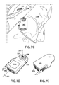
- FIGS. 7A-7I depict various views of an embodiment of the present LAL patient supports, including a mattress, an LAL coverlet, and another one of the present airflow units.
- FIGS. 8A-8B depict various views of another one of the present airflow units for LAL patient supports such as the one depicted in FIGS. 1A-4 .
- FIG. 9 depicts a partially cutaway perspective view of another one of the present airflow units for LAL patient supports such as the one depicted in FIGS. 1A-4 .
- Coupled is defined as connected, although not necessarily directly, and not necessarily mechanically; two items that are “coupled” may be unitary with each other.
- the terms “a” and “an” are defined as one or more unless this disclosure explicitly requires otherwise.
- the term “substantially” is defined as largely but not necessarily wholly what is specified (and includes what is specified; e.g., substantially 90 degrees includes 90 degrees and substantially parallel includes parallel), as understood by a person of ordinary skill in the art. In any disclosed embodiment, the terms “substantially,” “approximately,” and “about” may be substituted with “within [a percentage] of” what is specified, where the percentage includes 0.1, 1, 5, and 10 percent.
- a device, system, or structure that is configured in a certain way is configured in at least that way, but it can also be configured in other ways than those specifically described.
- Some of the present embodiments include systems configured (e.g., with components configured) to aid in prevention of decubitus ulcer formation and/or to remove moisture and/or heat from the patient.
- some embodiments include a multi-layer patient support (e.g., support system) that can be used in conjunction with a variety of support surfaces, such as an inflatable mattress, a foam mattress, a gel mattress, a water mattress, or a RIK® Fluid Mattress of a hospital bed.
- features of the multi-layer support system can help to remove moisture from the patient, while features of the mattress can aid in the prevention and/or healing of decubitus ulcers by further lowering interface pressures at areas of the skin in which external pressures are typically high, such as, for example, at bony prominences such as the heel and the hip area of the patient.
- Other embodiments include one of the present multi-layer supports in conjunction with a chair or other support platform.
- a single-use or one-time use support system is a support system for single-patient use applications that is formed of material that is disposable and/or inexpensive and/or manufactured and/or assembled in a low-cost manner and is intended to be used for a single patient over a brief period of time, such as an hour(s), a day, or multiple days (e.g., 2, 5, or more days).
- a support system or low-air-loss (LAL) coverlet 100 shown coupled to a mattress 150 (e.g., a fluid-fillable mattress).
- support system 100 is configured to extend around the sides of mattress 150 , and to and around a portion of the lower surface of mattress 150 .
- Mattress 150 can be any configuration known in the art for supporting a person.
- mattress 150 may be an alternating-pressure-pad-type mattress or other type of mattress using air to inflate or pressurize a cell or chamber within the mattress.
- mattress 150 does not utilize air to support a person.
- support system 100 may be used in seating applications (e.g., wheelchairs, chairs, recliners, benches, etc.).
- FIG. 1A depicts a partially cutaway perspective view of a support system 100 mounted on a mattress 150 .
- support system 100 comprises first layer 110 and second layer 120 .
- FIG. 1A support system 100 is shown coupled to mattress 150 .
- FIG. 1B depicts the underside of mattress 150 with support system 100 coupled to mattress 150 .
- support system 100 may be coupled to mattress 150 via a coupling member 125 , as shown in FIG. 1B .
- coupling member 125 may comprise elastic (e.g., an elastic strap).
- coupling member 125 comprises one or more of: a hook-and-loop fastener, buttons, snaps, straps, zippers, and/or other suitable coupling devices or components.
- support system 100 may be coupled to mattress 150 by tucking material (e.g. a first layer 110 and/or a second layer 120 ) from support system 100 under mattress 150 .
- tucking material e.g. a first layer 110 and/or a second layer 120
- coupling member 125 may couple support system 100 to a seat (not shown).
- first layer 110 and second layer 120 are joined at sealed end 112 and sealed sides 114 to form an airtight seal (e.g., such that one or more chambers, channels, and/or flow paths are formed between first layer 110 and second layer 120 ).
- Sealed end 112 and sealed sides 114 may be stitched, glued, epoxied, welded, radio-frequency welded, or otherwise joined such that an airtight or substantially airtight seal is formed.
- first layer 110 and second layer 120 are not joined along one edge, forming opening 116 .
- first layer 110 and 120 are joined by a vent material that allows for the ready passage of air and moisture vapor through opening 116 .
- opening 116 comprises a valve, a slit, or a hole through which air and moisture vapor may pass.
- FIG. 2 depicts a cross-sectional view of support system 100 taken along section line 2 - 2 in FIG. 1B , showing channels 130 formed between first layer 110 and second layer 120 .
- second layer 120 is in partial contact with first layer 110 such that a plurality of channels 130 are formed between first layer 110 and second layer 120 .
- having second layer 120 in partial contact with first layer 110 allows air to flow through channels 130 when a person is laying on system 100 while the system is coupled to and/or supported by a mattress.
- second layer 120 comprises a plurality of protrusions 135 .
- second layer 120 may comprise a cellular cushioning material.
- second layer 120 may comprise a plastic sheet material (e.g., polyethylene).
- protrusions 135 comprise encapsulated cells or volumes (e.g., regularly spaced encapsulated cells or volumes).
- the encapsulated cells or volumes may contain a volume of gas (e.g., most or all of the encapsulated cells or volumes may be filled with air or other gas).
- the encapsulated cells or volumes may, in some embodiments, have a substantially circular shape or cross-section.
- system 100 comprises a spacer layer (disposed where protrusions 135 are shown, such as spacer layer 404 in FIG. 9 ) between first layer 110 and second layer 120 .
- a spacer layer is configured to provide a space between first layer 110 and second layer 120 , and to provide flow paths 130 (e.g., via pores, channels, or the like) to permit system 100 to function as described in this disclosure.
- this spacer layer includes a layer of open-celled foam, such as, a large-celled and open-celled polyurethane (PU) foam.
- PU polyurethane
- an open-celled PU foam has a density of 1.8-2.2 lbs per cubic foot, a pore size (visual) of 30 ⁇ 10 pores per inch and is marketed under the trade name DRI-FAST by Foamex, U.S.A.
- Other types of materials may also be used for a spacer layer, such as, for example, fibrous and/or any other materials or configurations that provide the described flow paths 130 between first layer 110 and second layer 120 .
- FIG. 3 discloses a cross-sectional view of support system 100 and mattress 150 taken along section line 3 - 3 in FIG. 1A .
- support system 100 comprises first layer 110 , second layer 120 , and an airflow unit 140 .
- support system 100 is configured such that first layer 110 is the layer that will contact a patient 20 that is supported by support system 100 .
- Support system 100 is further configured such that second layer 120 is between first layer 110 and mattress 150 .
- first layer 110 comprises a material that is vapor-permeable and liquid-impermeable.
- First layer 110 may be air permeable or air-impermeable.
- An example of a material that is vapor-permeable, liquid-impermeable, and air-impermeable is a hospital bedsheet comprising polyurethane.
- An example of a material that is vapor-permeable, liquid-impermeable, and air permeable is a hospital bedsheet comprising polytetrafluoroethylene.
- second layer 120 comprises a material that is vapor-permeable and liquid-impermeable. Second layer 120 may be air permeable or substantially air-impermeable.
- airflow unit 140 is located between second layer 120 and mattress 150 if system 100 is coupled to mattress 150 .
- Airflow unit 140 is in fluid communication with channels 130 between first layer 110 and second layer 120 .
- airflow unit 140 may comprise a guard 145 or other partition to prevent material from blocking the inlet or outlet of airflow unit 140 .
- airflow unit 140 is configured to pull air into opening 116 through channels 130 toward airflow unit 140 by applying a negative pressure to channels 130 .
- the present airflow units comprise an air mover (e.g., a fan, a pump, a blower, or the like).
- an air mover e.g., a fan, a pump, a blower, or the like.
- an air mover e.g., a 12 volt DC fan such as an ACT-RX Technology Corporation CeraDyna Fan (Model 5115).
- airflow unit 140 is 5.1 cm wide by 5.1 cm tall by 1.5 cm thick and weighs approximately 25 grams.
- airflow unit 140 produces an air flow of about 4.10 cfm (0.12 cmm), a maximum air pressure of 16.08 mm-H 2 O, and has an acoustical noise rating of 37.5 dB(A).
- This CeraDyna Fan is a centrifugal fan that is configured to move air perpendicular to the axis of rotation of the blades.
- airflow unit 140 can be positioned adjacent to second layer 120 , allowing for a more compact overall design of support system 100 .
- airflow unit 140 may be coupled to second layer 120 and first layer 110 with a substantially airtight seal so that air does not flow around airflow unit 140 .
- airflow unit 140 can be disposed in a location that is not between mattress 150 and the patient, such that airflow unit 140 will not adversely affect the patient's comfort.
- air mover 140 may be placed between the patient and mattress 150 without adversely affecting the patient's comfort.
- air mover 140 may be external to and/or remote from first layer 110 and second layer 120 with appropriate connecting members such as tubing, piping or duct work, etc. In such embodiments, air mover 140 is in fluid communication with channels or flow paths 130 .
- air mover 140 may be a pump that is remote from and coupled to first layer 110 and second layer 120 with tubing and/or a valve.
- air mover 140 may be configured to apply a positive pressure to channels 130 .
- Air mover 140 may be configured to intake ambient air and blow the ambient air through channels 130 away from air mover 140 and toward opening 116 .
- FIG. 4 depicts a top view of a patient 20 laying on first layer 110 of support system 100 .
- moisture e.g., perspiration
- the amount of accumulated moisture may be expressed in terms of relative humidity (%), which is generally describes the amount of water vapor that exists in a gaseous mixture of air and water vapor, compared to the upper limit of what it could be at the same temperature and bulk pressure.
- the present embodiments of system 100 and/or airflow units 140 can be configured such that if the air mover is activated while a patient is disposed on the coverlet: moisture vapor will transfer through the first layer into the plurality of channels; and the air mover will transfer the moisture vapor from the plurality of channels, through the opening of the first housing member, and to an exterior of the coverlet.
- FIG. 5 depicts an exploded perspective view of an embodiment 140 a of the present airflow units for LAL patient supports such as the one depicted in FIGS. 1A-4 .
- second housing member 208 is configured to help prevent or reduce the likelihood of foam or fabric entering the air mover when airflow unit 140 is in use.
- openings 204 are at least partially defined by a crosshair shape in first housing member 200 .
- Other embodiments may have similar configurations, or may include gratings or perforated openings (e.g., multiple smaller openings).
- airflow unit 140 a comprises a first housing member 200 having at least one opening 204 in fluid communication with the plurality of flow paths or channels 130 ; a second housing member 208 configured to be coupled to first housing member 200 ; and an air mover 212 disposed between first housing member 200 and second housing member 208 .
- airflow unit 140 a is configured to be coupled to coverlet 100 such that the air mover can be activated to move air through the plurality of channels or flow paths 130 .
- first housing member 200 is coupled to second housing member 208 (e.g., via an adhesive and/or a gasket 216 which may, for example, be an adhesive gasket).
- gasket 216 includes a peripheral portion 220 and an air-mover portion 224 .
- Peripheral portion 220 extends around and is configured to seal at least a portion (e.g., up to and including all) of the peripheral seam or joint between first housing member 200 and second housing member 208 .
- Air-mover portion 224 of gasket 216 is configured to extend around one or more openings 204 through which air mover 212 can fluidly communicate with coverlet 100 when airflow unit 140 a is coupled to coverlet 100 (e.g., such that air-mover portion 224 substantially prevents leaks at the interface between air mover 212 and first housing member 200 ).
- airflow unit 140 comprises an interface gasket 228 disposed between first housing member 200 and second layer 120 of coverlet 100 .
- Interface gasket 228 may, for example, be an adhesive gasket and/or may otherwise be coupled to first housing member 200 and second layer 120 by adhesive.
- interface gasket 228 is configured to substantially seal the interface between first housing member 200 and coverlet 100 (second layer 120 ).
- gasket 216 and interface gasket 228 are formed from the same piece of gasket material.
- gasket 216 is smaller than interface gasket 228 such that gasket 216 is cut out of interface gasket 228 , as shown, conserving gasket material and simplifying manufacturing and shipping of components.
- gasket 216 and 228 can be cut out of a common piece of gasket material and shipped in a single layer (e.g., with a common backing material, such as wax paper), such as in a kit, such that gasket 216 and interface gasket 228 can be removed from the backing material (not shown) to assemble airflow unit 140 a .
- interface gasket includes a central hole or opening 232 that is configured to be positioned over a corresponding hole or opening 236 in second layer 120 of coverlet 100 .
- first housing member 200 and second housing member 208 cooperate to define at least one opening 240 (e.g., as shown, a plurality of openings 240 ).
- the perimeter of second housing member 208 includes a plurality of indented portions configured such that when second housing member 208 is coupled to first housing member 200 , the indented portions of second housing member 208 leave spaces between second housing member 208 and first housing member 200 (openings 240 ) through which air mover 212 can push or pull air.
- second layer 120 has an inner side 244 facing toward first layer 110 , and an outer side 248 facing away from first layer 110 .
- airflow unit 140 a is configured to be coupled to second layer 120 such that second housing member 208 is disposed on outer side 244 of second layer 120 (e.g., such that interface gasket 228 is coupled to outer side 244 of second layer 120 ).
- second housing member 208 of airflow unit 140 a comprises one or more (e.g., two) pins (not shown), and air mover 212 comprises one or more holes 252 corresponding to the one or more pins, such that if the one or more pins extend into the one or more corresponding holes 252 , and second housing member 208 is coupled to first housing member 200 , air mover 212 is substantially fixed relative to second housing member 208 (e.g., and first housing member 200 ).
- airflow unit 140 a also includes an electrical plug or connection 256 connected to second housing member 208 , and electrically coupled to air mover 212 such that a power source (e.g., battery, power outlet, and/or the like) can be removably coupled to airflow unit 140 a to power air mover 212 .
- a power source e.g., battery, power outlet, and/or the like
- first housing member 200 may be omitted, such that second housing member 208 is coupled to coverlet 100 (e.g., second layer 120 ) by gasket 216 .
- peripheral portion 220 may extend around the entire perimeter of second housing member 208 .
- a second gasket or grating member may be coupled to opening 236 in coverlet 100 to provide a crosshair or other grating structure to prevent or reduce the likelihood of fabric or foam entering air mover 212 .
- FIGS. 6A-6D depict various views of another embodiment 140 b of the present airflow units for LAL patient supports such as the one depicted in FIGS. 1A-4 .
- Airflow unit 140 b is similar in some respects to airflow unit 140 a , and the differences will be primarily described.
- first housing member 200 a is configured to be (and in certain of the present support systems, is) disposed between first layer 110 and second layer 120 of coverlet 100 .
- first housing member 200 a can be disposed between first and second layers 110 and 120
- second housing member 208 a can be coupled to first housing member 200 a such that air mover 212 is disposed between second layer 120 and second housing member 208 a .
- first housing member 200 a includes two or more protrusions 260 configured to extend through second layer 120 of coverlet 100 (or, in other embodiments, through first layer 110 ) such that second housing member 200 b can be coupled to protrusions 260 on an opposite side of second layer 120 (e.g., such that second housing member 208 a is disposed on outer side 244 ( FIG. 3 ) of second layer 120 ).
- Second housing member 208 a can be coupled and/or connected to protrusions 260 in any suitable fashion (e.g., screws, adhesive, barbs, friction, snaps, etc.).
- each of protrusions 260 includes a barb 264
- second housing member 208 includes a plurality of corresponding holes 268 and tabs 272 , such that protrusions 260 can be pressed through the corresponding holes 268 such that barbs 264 engage or are otherwise coupled to tabs 272 .
- second layer 120 (or first layer 110 ) is disposed (e.g., pinched) between first and second housing members 200 a and 208 b
- airflow unit 140 b can be coupled to coverlet (e.g., second layer 120 ) without gaskets, adhesive, screws, or additional hardware.
- holes 268 may be omitted and tabs can be provided on an interior side of second housing member 208 a.
- airflow unit 140 b (e.g., first housing member 200 a and/or second housing member 208 a ) includes one or more (e.g., two, three, four) pins 276 , and air mover 212 comprises one or more corresponding holes 252 corresponding to the one or more pins 276 , such that if pins 276 extend into holes 252 , and second housing member 208 a is coupled to first housing member 200 a , air mover 212 is substantially fixed relative to second housing member 208 a .
- second housing member 208 a includes at least one opening (e.g., a plurality of openings) 280 .
- second housing member 208 a includes a plurality of openings around the perimeter or a peripheral surface of second housing member 208 a.
- FIGS. 7A-7I depict various views of an embodiment of the present LAL patient supports, including a mattress 150 a , an LAL coverlet 100 a , and another embodiment 140 c of the present airflow units.
- FIG. 7A depicts an edge (e.g., a foot end) of a mattress 150 a .
- FIG. 7B depicts an internal side of a coverlet 100 a (e.g., a portion of second layer 120 configured to be disposed adjacent the portion of mattress 150 a depicted in FIG. 7A .
- FIG. 7C depicts another embodiment 140 c of an airflow unit with mattress 150 a ( FIG. 7A ) and coverlet 100 a ( FIG. 7B ).
- coverlet 100 a is substantially similar to coverlet 100 .
- coverlet 100 a comprises a coverlet comprising: a first layer 110 (e.g., comprising a vapor-permeable and liquid-impermeable material), and a second layer 120 (e.g., comprising a vapor-permeable and liquid-impermeable material) coupled to first layer 110 such that a plurality of flow paths 130 are formed between first layer 110 and second layer 120 , as described above.
- coverlet 100 a comprises a coupling member 300 in fluid communication with flow paths 130 , such that airflow unit 140 c can be coupled to coupling member 300 to enable fluid communication between airflow unit 140 c and flow paths 130 .
- Coupling member 300 can comprise a resilient material such as silicone, polyvinyl chloride (PVC), rubber, and/or latex.
- coupling member is circular (e.g., has a ring shape), and includes a tapered internal edge 304 to facilitate coupling to airflow unit 140 c.
- mattress 150 a includes a compartment 308 configured to removably receive airflow unit 140 c .
- mattress 150 a includes a sheet of material 312 forming a generally rectangular pocket with an open bottom.
- mattress 150 a also comprises a passage 316 (through material 312 ) configured to permit coupling member 300 (of coverlet 100 a ) to be coupled to airflow unit 140 c if the airflow unit is disposed in compartment 308 .
- Material 312 can comprise, for example, one or more of the same material(s) that form mattress 150 a.
- FIGS. 7D-7I depict various views of airflow unit 140 c and components of airflow unit 140 c .
- Airflow unit 140 c is similar to airflow units 140 , 140 a , and 140 b , and the differences are primarily described here.
- airflow unit 140 c comprises: a first housing member 200 b ; a second housing member 208 b coupled to first housing member 200 b ; and an air mover 212 disposed between first and second housing members 200 b and 208 b .
- first and second housing members 200 b and 208 b (e.g., one or both of the first and second housing members) define a first opening 204 a having a first axis 206 , and a second opening 280 a having a second axis 282 that is not parallel (e.g., perpendicular, as shown) to first axis 206 .
- first axis 206 may be parallel to second axis 282 .
- Airflow unit 140 c (e.g., at least one of first and second housing members 200 b and 208 b ) also comprises a flange 320 surrounding first opening 204 a .
- Flange 320 is configured to be removably coupled to coupling member 300 of coverlet 100 b .
- flange 320 is configured to fit into coupling member 320 (e.g., such that coupling member 300 stretches slightly to fit snugly around flange 320 to seal the interface therebetween) to permit or enable fluid communication between airflow unit 140 c and flow paths or channels 130 of coverlet 100 b .
- flange 320 may be configured to fit around coupling member 300 .
- flange 320 is unitary with first housing member 200 b and extends (e.g., outwardly) from first housing member 200 b in a direction that is substantially parallel to first axis.
- airflow unit 140 c also includes guide vanes 324 configured to align fluid flowing through first opening 204 a .
- guide vanes are unitary with second housing member 208 b and are configured to extend from second housing member 208 b such that when first and second housing members 200 b and 208 b are coupled together, at least part of guide vanes 324 extend through first opening 204 a , and/or prevent or decrease the likelihood of fabric or other items entering first opening 204 a .
- guide vanes 324 may be omitted, and/or airflow unit 140 c (e.g., first housing member 200 b ) may include a grating or the like over or dividing first opening 204 a to align fluid flowing through first opening and/or reduce the likelihood of items entering first opening 204 a .
- airflow unit 140 c also comprises grating member 328 that is disposed between second opening 280 a and air mover 212 to reduce the likelihood of fingers or other objects extending into air mover 212 (e.g., during use).
- grating member 328 may be unitary with first housing member 200 b and/or second housing member 208 b.
- airflow unit 140 c is also different from airflow units 140 a and 140 b in that air mover 212 is laterally spaced from first opening 204 a .
- first and second housing members 200 b and 208 b are configured to provide a space between air mover 212 and one or both of first and second housing members 200 b and 208 b , respectively.
- first and second housing members 200 b and 208 b include spacer members 332 at the base of pins 276 .
- first housing member 200 b and/or second housing member 208 b may be provided with enlarged flow paths (e.g., non-planar outer walls) between first opening 204 a and air mover 212 to permit air to flow therebetween.
- coverlet 100 a , mattress 150 a , and airflow unit 140 c are configured such that the open end (shown at bottom in FIG. 7A ) of compartment 308 faces downward when the mattress is configured to support a patient.
- Airflow unit 140 c can thus be inserted in an upward direction (with the end closes to first opening 204 a facing upward) such that first opening 204 a and flange 320 aligned with passage 316 (e.g., such that flange 320 (if long enough) can extend through passage 316 .
- coverlet 100 a can be extended over mattress 150 a such that second layer 120 is adjacent (and/or closer than first layer 110 to) mattress 150 and coupling member 300 can be aligned with passage 316 and coupling member 320 .
- Coupling member 300 can then be pressed or otherwise disposed over and around flange 320 to permit fluid communication between airflow unit 140 c (air mover 212 ) and flow paths or channels 130 of coverlet 100 a .
- airflow unit 140 c is configured to “pull” air from channels or flow paths 130 , through first opening 204 a , into air mover 212 , and out second opening 280 a .
- airflow unit 140 c can be configured draw air through second opening 280 a , into air mover 212 , and to “push” the air into channels or flow paths 130 through first opening 200 b.
- FIGS. 8A-8B depict various views of another embodiment of the present airflow units for LAL patient supports such as the one depicted in FIGS. 1A-4 . More particularly, FIGS. 8A-8B depict an alternate embodiment of a second housing member 208 c that is configured for use with first housing member 200 a of FIGS. 6A-6D in the manner described above.
- second housing member 208 c differs from second housing member 200 a in that it comprises a flange 336 configured to be coupled to a conduit (not shown) such that an air mover can be coupled to the conduit for fluid communication between the air mover and a coverlet (e.g., the plurality of flowpaths 130 of the coverlet).
- a conduit such as a tube or the like can be coupled to an air mover such as a blower that is remote from second housing member 208 c (e.g., disposed in a footboard or external unit) to move air into or out of the coverlet.
- second housing member is not configured to house an air mover, pins 276 and openings 280 can be, and are shown, omitted.
- FIG. 9 depicts a partially cutaway perspective view of another embodiment of the present airflow units for LAL patient supports such as the one depicted in FIGS. 1A-4 .
- first housing member 200 d and second housing member 208 d are configured to be coupled to the coverlet such that air mover 212 is disposed between first layer 110 and second layer 120 .
- first housing member 200 d does not include an opening and is configured to be coupled to the coverlet such that protrusions 260 extend through first layer 110 to couple to second housing member 208 d (which is configured to be disposed between first layer 110 and second layer 120 .
- first housing member 200 d can be coupled (e.g., via adhesive, stitches, rivets, etc.) to an interior surface of first layer 110 such that both of first housing member 200 d and second housing member 208 d are disposed between first layer 110 and second layer 120 .
- second housing member 208 d includes openings 280 configured to permit fluid communication between air mover 212 and channels 130 such that air mover 212 can draw fluid through channels 130 , through openings 280 , into air mover 120 , and out of the airflow unit (and coverlet) through an opening 400 (or draw fluid in through opening 400 and push it to channels 130 ).
- the coverlet includes a spacer layer 404 , which may be any suitable material, as discussed above, which permits or provides channels or flowpaths 130 between first layer 110 and second layer 120 .
Abstract
Description
Claims (24)
Priority Applications (1)
| Application Number | Priority Date | Filing Date | Title |
|---|---|---|---|
| US13/343,580 US8918930B2 (en) | 2011-01-04 | 2012-01-04 | Methods and apparatuses for low-air-loss (LAL) coverlets and airflow units for coverlets |
Applications Claiming Priority (2)
| Application Number | Priority Date | Filing Date | Title |
|---|---|---|---|
| US201161429696P | 2011-01-04 | 2011-01-04 | |
| US13/343,580 US8918930B2 (en) | 2011-01-04 | 2012-01-04 | Methods and apparatuses for low-air-loss (LAL) coverlets and airflow units for coverlets |
Publications (2)
| Publication Number | Publication Date |
|---|---|
| US20120167303A1 US20120167303A1 (en) | 2012-07-05 |
| US8918930B2 true US8918930B2 (en) | 2014-12-30 |
Family
ID=46379397
Family Applications (1)
| Application Number | Title | Priority Date | Filing Date |
|---|---|---|---|
| US13/343,580 Active 2032-12-31 US8918930B2 (en) | 2011-01-04 | 2012-01-04 | Methods and apparatuses for low-air-loss (LAL) coverlets and airflow units for coverlets |
Country Status (1)
| Country | Link |
|---|---|
| US (1) | US8918930B2 (en) |
Cited By (30)
| Publication number | Priority date | Publication date | Assignee | Title |
|---|---|---|---|---|
| WO2016086073A2 (en) | 2014-11-24 | 2016-06-02 | Huntleigh Technology Limited | Moisture control coverlet |
| USD778639S1 (en) * | 2015-11-13 | 2017-02-14 | Ascion, Llc | Mattress |
| US10258163B2 (en) | 2016-04-04 | 2019-04-16 | Ashley Furniture Industries, Inc. | Mattress permitting airflow for heating and cooling |
| USD877915S1 (en) | 2018-09-28 | 2020-03-10 | Stryker Corporation | Crib assembly |
| USD879966S1 (en) | 2018-09-28 | 2020-03-31 | Stryker Corporation | Crib assembly |
| USD888963S1 (en) | 2018-09-28 | 2020-06-30 | Stryker Corporation | Cover assembly for a patient support |
| USD888962S1 (en) | 2018-09-28 | 2020-06-30 | Stryker Corporation | Cover assembly for a patient support |
| USD888964S1 (en) | 2018-09-28 | 2020-06-30 | Stryker Corporation | Crib assembly for a patient support |
| USD890914S1 (en) | 2018-10-31 | 2020-07-21 | Stryker Corporation | Pump |
| USD892159S1 (en) | 2018-10-31 | 2020-08-04 | Stryker Corporation | Display screen with animated graphical user interface |
| US20200253388A1 (en) * | 2012-02-21 | 2020-08-13 | Hill-Rom Services, Inc. | Topper with targeted fluid flow distribution |
| USD893543S1 (en) | 2018-10-31 | 2020-08-18 | Stryker Corporation | Display screen with graphical user interface |
| USD894223S1 (en) | 2018-10-31 | 2020-08-25 | Stryker Corporation | Display screen with animated graphical user interface |
| USD894226S1 (en) | 2018-10-31 | 2020-08-25 | Stryker Corporation | Display screen or portion thereof with graphical user interface |
| USD894957S1 (en) | 2018-10-31 | 2020-09-01 | Stryker Corporation | Display screen or portion thereof with graphical user interface |
| USD894956S1 (en) | 2018-10-31 | 2020-09-01 | Stryker Corporation | Display screen or portion thereof with graphical user interface |
| USD901940S1 (en) | 2018-09-28 | 2020-11-17 | Stryker Corporation | Patient support |
| US20210038453A1 (en) * | 2009-08-31 | 2021-02-11 | Gentherm Incorporated | Climate-controlled topper member for beds |
| USD919333S1 (en) | 2019-08-27 | 2021-05-18 | Casper Sleep Inc. | Mattress |
| USD927889S1 (en) | 2019-10-16 | 2021-08-17 | Casper Sleep Inc. | Mattress layer |
| US11116326B2 (en) | 2017-08-14 | 2021-09-14 | Casper Sleep Inc. | Mattress containing ergonomic and firmness-regulating endoskeleton |
| US11173085B2 (en) | 2017-12-28 | 2021-11-16 | Stryker Corporation | Mattress cover for a mattress providing rotation therapy to a patient |
| US11202517B2 (en) | 2014-04-21 | 2021-12-21 | Casper Sleep Inc. | Mattress |
| US11219567B2 (en) | 2018-09-28 | 2022-01-11 | Stryker Corporation | Patient support |
| US11241349B2 (en) | 2018-09-28 | 2022-02-08 | Stryker Corporation | Patient support including a connector assembly |
| US11241100B2 (en) | 2018-04-23 | 2022-02-08 | Casper Sleep Inc. | Temperature-regulating mattress |
| US11246775B2 (en) | 2017-12-28 | 2022-02-15 | Stryker Corporation | Patient turning device for a patient support apparatus |
| US11540964B2 (en) | 2018-02-27 | 2023-01-03 | Hill-Rom Services, Inc. | Patient support surface control, end of life indication, and x-ray cassette sleeve |
| US11559451B2 (en) | 2018-10-31 | 2023-01-24 | Stryker Corporation | Fluid source for supplying fluid to therapy devices |
| USD977109S1 (en) | 2018-09-28 | 2023-01-31 | Stryker Corporation | Crib assembly for a patient support |
Families Citing this family (11)
| Publication number | Priority date | Publication date | Assignee | Title |
|---|---|---|---|---|
| US9138064B2 (en) | 2013-01-18 | 2015-09-22 | Fxi, Inc. | Mattress with combination of pressure redistribution and internal air flow guides |
| US9392875B2 (en) | 2013-01-18 | 2016-07-19 | Fxi, Inc. | Body support system with combination of pressure redistribution and internal air flow guide(s) for withdrawing heat and moisture away from body reclining on support surface of body support system |
| US20140259400A1 (en) * | 2013-03-13 | 2014-09-18 | Stryker Corporation | Patient support with microclimate management system |
| US20150121621A1 (en) * | 2013-11-06 | 2015-05-07 | Mark Aramli | Remote operation of a bedding climate control apparatus |
| CA2968547C (en) * | 2014-11-24 | 2023-03-07 | Huntleigh Technology Limited | Moisture control system |
| US10405665B2 (en) | 2015-02-13 | 2019-09-10 | L&P Property Management Company | Pocketed spring comfort layer and method of making same |
| US10813462B2 (en) | 2015-02-13 | 2020-10-27 | L&P Property Management Company | Pocketed spring comfort layer and method of making same |
| US9943173B2 (en) | 2015-02-13 | 2018-04-17 | L&P Property Management Company | Pocketed spring comfort layer and method of making same |
| US9968202B2 (en) | 2015-02-13 | 2018-05-15 | L&P Property Management Company | Pocketed spring comfort layer and method of making same |
| EP3641962A4 (en) * | 2017-06-20 | 2020-11-25 | L&P Property Management Company | Pocketed spring comfort layer and method of making same |
| US11033116B2 (en) | 2019-08-23 | 2021-06-15 | L&P Property Management Company | Dual-sided vented pocketed spring comfort layer |
Citations (100)
| Publication number | Priority date | Publication date | Assignee | Title |
|---|---|---|---|---|
| US2826244A (en) | 1954-02-24 | 1958-03-11 | Curtiss Wright Corp | Seat cushion of foam-type material and method of fabricating same |
| US3735559A (en) | 1972-02-02 | 1973-05-29 | Gen Electric | Sulfonated polyxylylene oxide as a permselective membrane for water vapor transport |
| US4185341A (en) | 1976-11-08 | 1980-01-29 | The Institute Of Orthopaedics | Support appliance |
| US4483030A (en) | 1982-05-03 | 1984-11-20 | Medisearch Pr, Inc. | Air pad |
| US4825488A (en) | 1988-04-13 | 1989-05-02 | Bedford Peter H | Support pad for nonambulatory persons |
| US4853992A (en) | 1988-07-22 | 1989-08-08 | Kaung M Yu | Air cooled/heated seat cushion |
| JPH0211144Y2 (en) | 1985-07-24 | 1990-03-20 | ||
| US4997230A (en) | 1990-01-30 | 1991-03-05 | Samuel Spitalnick | Air conditioned cushion covers |
| US5007123A (en) | 1990-07-05 | 1991-04-16 | Comfortex, Inc. | Flexible covering for reducing moisture/vapor/bacteria transmission |
| US5035014A (en) | 1990-08-10 | 1991-07-30 | Ssi Medical Services, Inc. | Comfort guard for low air loss patient support systems |
| US5249319A (en) | 1992-09-09 | 1993-10-05 | Mellen Air Manufacturing, Inc. | Low air loss, pressure relieving mattress system |
| US5416935A (en) | 1993-11-29 | 1995-05-23 | Nieh; Rosa L. | Cushion surface air conditioning apparatus |
| US5473783A (en) | 1994-04-04 | 1995-12-12 | Allen; Randall W. | Air percolating pad |
| US5498278A (en) | 1990-08-10 | 1996-03-12 | Bend Research, Inc. | Composite hydrogen separation element and module |
| US5611096A (en) | 1994-05-09 | 1997-03-18 | Kinetic Concepts, Inc. | Positional feedback system for medical mattress systems |
| US5640728A (en) | 1993-09-30 | 1997-06-24 | Graebe; Robert H. | Ventilated access interface and cushion support system |
| US5647079A (en) | 1996-03-20 | 1997-07-15 | Hill-Rom, Inc. | Inflatable patient support surface system |
| US5681368A (en) | 1995-07-05 | 1997-10-28 | Andrew Corporation | Dehumidifier system using membrane cartridge |
| US5701621A (en) | 1989-12-04 | 1997-12-30 | Supracor Systems Corporation | Liner for overlaying a mattress |
| US5755000A (en) | 1994-05-25 | 1998-05-26 | Egerton Hospital Equipment Limited | Low air-loss mattresses |
| EP0870449A2 (en) | 1997-03-11 | 1998-10-14 | ORSA S.r.l. | Bed mattress with variable characteristics of carrying capacity throughout its length |
| US5882349A (en) | 1995-12-26 | 1999-03-16 | Geomarine Systems, Inc. | Patient moisture control support surface coverlet |
| US5887304A (en) | 1997-07-10 | 1999-03-30 | Von Der Heyde; Christian P. | Apparatus and method for preventing sudden infant death syndrome |
| JPH11164757A (en) | 1997-12-03 | 1999-06-22 | Kachi:Kk | Human body support device |
| JPH11169262A (en) | 1997-12-09 | 1999-06-29 | Kachi:Kk | Human body supporting device |
| US5926884A (en) | 1997-08-05 | 1999-07-27 | Sentech Medical Systems, Inc. | Air distribution device for the prevention and the treatment of decubitus ulcers and pressure sores |
| JPH11332697A (en) | 1998-05-27 | 1999-12-07 | Molten Corp | Body pressure dispersing mat |
| US6065166A (en) | 1996-10-17 | 2000-05-23 | O.R. Comfort, Llc | Surgical support cushion apparatus and method |
| JP2000152854A (en) | 1998-09-16 | 2000-06-06 | Osaka Nishikawa:Kk | Mattress |
| US6085369A (en) * | 1994-08-30 | 2000-07-11 | Feher; Steve | Selectively cooled or heated cushion and apparatus therefor |
| US6182315B1 (en) | 1998-12-30 | 2001-02-06 | Seven States Enterprise Co., Ltd. | Structure of three-layer venting mattress |
| US6272707B1 (en) | 1998-11-12 | 2001-08-14 | Colbond Inc. | Support pad |
| US6288076B1 (en) | 1996-02-29 | 2001-09-11 | The Research Foundation Of State Unversity Of New York | Antimicrobial compositions |
| US20010023512A1 (en) | 1999-01-08 | 2001-09-27 | Hill-Rom, Inc. | Check valve for mattress assembly |
| US6336237B1 (en) | 2000-05-11 | 2002-01-08 | Halo Innovations, Inc. | Mattress with conditioned airflow |
| US6341395B1 (en) | 2000-06-20 | 2002-01-29 | Yu-Chao Chao | Ventilating bed cushion |
| JP2002125809A (en) | 2000-10-23 | 2002-05-08 | Hitachi Hometec Ltd | Bedding |
| US6421859B1 (en) | 1999-06-03 | 2002-07-23 | Kci Licensing, Inc. | Patient support systems with layered fluid support mediums |
| US20020129449A1 (en) | 2000-06-01 | 2002-09-19 | Crown Therapeutic, Inc. | Moisture drying mattress with separate zone controls |
| US20020148047A1 (en) | 1999-12-09 | 2002-10-17 | The Procter & Gamble Company | Disposable, moisture vapour permeable, liquid impermeable mattress cover assembly having an improved structure |
| US6493889B2 (en) | 2001-01-29 | 2002-12-17 | Project Cool Air, Inc. | Cooling cover apparatus |
| US20030019044A1 (en) | 2000-03-09 | 2003-01-30 | Stefan Larsson | Bed |
| US6527832B2 (en) | 2000-06-27 | 2003-03-04 | Nisshin Steel Co., Ltd. | Device for recovery of hydrogen |
| US6546576B1 (en) | 2001-11-05 | 2003-04-15 | Ku-Shen Lin | Structure of a ventilated mattress with cooling and warming effect |
| US20030145380A1 (en) | 2002-02-06 | 2003-08-07 | Halo Innovations, Inc. | Furniture cover sheet |
| JP2003230605A (en) | 2001-12-06 | 2003-08-19 | Achilles Corp | Mattress |
| US6671911B1 (en) | 1999-05-21 | 2004-01-06 | Hill Engineering | Continuous wave cushioned support |
| US20040003471A1 (en) | 2002-02-01 | 2004-01-08 | Vansteenburg Kip | Reversed air mattress |
| US6709492B1 (en) | 2003-04-04 | 2004-03-23 | United Technologies Corporation | Planar membrane deoxygenator |
| US20040064888A1 (en) | 2002-10-07 | 2004-04-08 | Wan-Ching Wu | Bed with function of ventilation |
| JP2004188052A (en) | 2002-12-13 | 2004-07-08 | Toray Ind Inc | Bed sheet |
| US6779592B1 (en) | 1999-08-26 | 2004-08-24 | Seft Development Laboratory Co. | Cooling futon |
| US6782574B2 (en) | 2000-07-18 | 2004-08-31 | Span-America Medical Systems, Inc. | Air-powered low interface pressure support surface |
| WO2004082551A1 (en) | 2003-03-14 | 2004-09-30 | Hill-Rom Services, Inc. | Patient support |
| US20040214495A1 (en) | 1999-05-27 | 2004-10-28 | Foss Manufacturing Co., Inc. | Anti-microbial products |
| US20040237203A1 (en) | 1998-05-06 | 2004-12-02 | Romano James J. | Patient support |
| US20050011009A1 (en) | 2003-07-15 | 2005-01-20 | Hsiang-Ling Wu | Ventilation mattress |
| WO2005046988A1 (en) | 2003-11-12 | 2005-05-26 | Lancastria Limited | Laminated body support element |
| US20050188467A1 (en) | 2000-09-29 | 2005-09-01 | Lancastria Limited | Mattress |
| US20050278863A1 (en) | 2004-06-22 | 2005-12-22 | Riverpark Incorporated | Comfort product |
| US20060010607A1 (en) | 2002-10-23 | 2006-01-19 | Tcam Technologies, Inc. | Smart Decubitus Mat |
| US20060080778A1 (en) | 2004-04-30 | 2006-04-20 | Chambers Kenith W | Method and apparatus for improving air flow under a patient |
| WO2006122614A1 (en) | 2005-05-15 | 2006-11-23 | Phi-Ton Holding Bv | Method for producing pillows and cushions with spacer fabric, spacer woven fabric and spacer knitted fabric |
| US7140495B2 (en) | 2001-12-14 | 2006-11-28 | 3M Innovative Properties Company | Layered sheet construction for wastewater treatment |
| WO2006105169A3 (en) | 2005-03-28 | 2006-12-14 | Bg Ind Inc | Improved mattress |
| WO2007003018A1 (en) | 2005-06-30 | 2007-01-11 | Imhold, Naamloze Vennootschap | Improved pillow, mattress or the like. |
| US20070056116A1 (en) | 2005-09-09 | 2007-03-15 | Vintage Bedding, Inc. | Mattress with air passageways |
| WO2007034311A2 (en) | 2005-09-25 | 2007-03-29 | Asc N.V. Belgie | Support member and mattress |
| US20070079077A1 (en) * | 2002-04-29 | 2007-04-05 | Baines Mandeep S | System, method, and computer program product for shared memory queue |
| US7240386B1 (en) | 2004-05-20 | 2007-07-10 | King Koil Licensing Company, Inc. | Multi-layer mattress with an air filtration foundation |
| US7290300B1 (en) | 2004-10-28 | 2007-11-06 | Indratech, Llc | Polyester fiber cushion applications |
| US20070261548A1 (en) | 2006-05-11 | 2007-11-15 | Kci Licensing, Inc., Legal Department, Intellectual Property | Multi-layered support system |
| US20070266499A1 (en) | 2006-05-09 | 2007-11-22 | Hill-Rom Services, Inc. | Pulmonary mattress |
| US20080022461A1 (en) | 2006-07-26 | 2008-01-31 | Kci Licensing, Inc., Legal Department, Intellectual Property | Patient support with welded materials |
| US20080028536A1 (en) | 2006-08-04 | 2008-02-07 | Charlesette Hadden-Cook | Mattress with cooling airflow |
| US7334280B1 (en) | 2006-08-11 | 2008-02-26 | Swartzburg Rick T | Ventilated mattress and method |
| US20080060131A1 (en) | 2004-10-21 | 2008-03-13 | Tompkins Kurt W | Portable Ventilation System |
| US7357830B2 (en) | 2003-10-01 | 2008-04-15 | Imes Management Ag | Device for dehumidifying room air |
| US20080098529A1 (en) | 2006-10-26 | 2008-05-01 | Thierry Flocard | Device and method for controlling humidity at the surface of a supporting item of the mattress type |
| US20080263776A1 (en) | 2007-04-30 | 2008-10-30 | Span-America Medical Systems, Inc. | Low air loss moisture control mattress overlay |
| EP2047770A1 (en) | 2007-10-09 | 2009-04-15 | Siegfried Heerklotz | Top mat for an upholstery body, especially user side for a mattress cover |
| US7631377B1 (en) | 2008-07-09 | 2009-12-15 | Sanford Alonzo W | Bed ventilator unit |
| US7637573B2 (en) | 2002-07-03 | 2009-12-29 | W.E.T. Automotive Systems Ag | Automotive vehicle seating insert |
| US20090322124A1 (en) | 2006-07-27 | 2009-12-31 | Tomas Barkow | Air-conditioned seat |
| US20100095461A1 (en) | 1998-05-06 | 2010-04-22 | Romano James J | Patient support surface |
| US20100122417A1 (en) | 2008-11-19 | 2010-05-20 | Kci Licensing, Inc. | Multi-Layered Support System |
| US20100175196A1 (en) | 2008-12-17 | 2010-07-15 | Patrick Lafleche | Patient support |
| US20100287701A1 (en) | 2009-03-30 | 2010-11-18 | Jacobo Frias | Inflatable Temperature Control System |
| EP2258242A1 (en) | 2009-06-04 | 2010-12-08 | Bodet & Horst GmbH & Co. KG | Mattress protector on the top of a mattress |
| US20110004997A1 (en) | 2009-07-09 | 2011-01-13 | Bob Barker Company, Inc. | Mattress with a Vented Cover |
| US20110010850A1 (en) | 2009-07-18 | 2011-01-20 | Jacobo Frias | Non-Inflatable Temperature Control System |
| US20110010855A1 (en) | 2009-07-17 | 2011-01-20 | Dennis Flessate | Therapy and Low Air Loss Universal Coverlet |
| US7886385B2 (en) | 2009-05-19 | 2011-02-15 | Eclipse International | Mattress with quilted zoned topper |
| US20110035880A1 (en) | 2008-03-31 | 2011-02-17 | Nicholas Cole | Mattress system |
| US7913332B1 (en) | 2007-04-30 | 2011-03-29 | James Louis Barnhart | Drawn air bed ventilator |
| EP1151698B1 (en) | 2000-05-03 | 2011-04-20 | Trlby Innovative LLC | Inflatable mattress systems and method of manufacture therefor |
| US7937791B2 (en) | 2004-04-30 | 2011-05-10 | Hill-Rom Services, Inc. | Pressure relief surface |
| US7937789B2 (en) | 2005-09-13 | 2011-05-10 | Steve Feher | Convective cushion for bedding or seating |
| US20110107514A1 (en) | 2009-08-31 | 2011-05-12 | Amerigon Incorporated | Climate-controlled topper member for medical beds |
| WO2011067720A1 (en) | 2009-12-01 | 2011-06-09 | Gabriele Zecca | System for receiving a user |
-
2012
- 2012-01-04 US US13/343,580 patent/US8918930B2/en active Active
Patent Citations (127)
| Publication number | Priority date | Publication date | Assignee | Title |
|---|---|---|---|---|
| US2826244A (en) | 1954-02-24 | 1958-03-11 | Curtiss Wright Corp | Seat cushion of foam-type material and method of fabricating same |
| US3735559A (en) | 1972-02-02 | 1973-05-29 | Gen Electric | Sulfonated polyxylylene oxide as a permselective membrane for water vapor transport |
| US4185341A (en) | 1976-11-08 | 1980-01-29 | The Institute Of Orthopaedics | Support appliance |
| US4483030A (en) | 1982-05-03 | 1984-11-20 | Medisearch Pr, Inc. | Air pad |
| JPH0211144Y2 (en) | 1985-07-24 | 1990-03-20 | ||
| US4825488A (en) | 1988-04-13 | 1989-05-02 | Bedford Peter H | Support pad for nonambulatory persons |
| US4853992A (en) | 1988-07-22 | 1989-08-08 | Kaung M Yu | Air cooled/heated seat cushion |
| US5701621A (en) | 1989-12-04 | 1997-12-30 | Supracor Systems Corporation | Liner for overlaying a mattress |
| US4997230A (en) | 1990-01-30 | 1991-03-05 | Samuel Spitalnick | Air conditioned cushion covers |
| US5007123A (en) | 1990-07-05 | 1991-04-16 | Comfortex, Inc. | Flexible covering for reducing moisture/vapor/bacteria transmission |
| US5035014A (en) | 1990-08-10 | 1991-07-30 | Ssi Medical Services, Inc. | Comfort guard for low air loss patient support systems |
| US5498278A (en) | 1990-08-10 | 1996-03-12 | Bend Research, Inc. | Composite hydrogen separation element and module |
| US5249319A (en) | 1992-09-09 | 1993-10-05 | Mellen Air Manufacturing, Inc. | Low air loss, pressure relieving mattress system |
| US5640728A (en) | 1993-09-30 | 1997-06-24 | Graebe; Robert H. | Ventilated access interface and cushion support system |
| US5416935A (en) | 1993-11-29 | 1995-05-23 | Nieh; Rosa L. | Cushion surface air conditioning apparatus |
| US5473783A (en) | 1994-04-04 | 1995-12-12 | Allen; Randall W. | Air percolating pad |
| US5611096A (en) | 1994-05-09 | 1997-03-18 | Kinetic Concepts, Inc. | Positional feedback system for medical mattress systems |
| US6353950B1 (en) | 1994-05-09 | 2002-03-12 | Kinetic Concepts, Inc. | Positional feedback system for medical mattress systems |
| US5755000A (en) | 1994-05-25 | 1998-05-26 | Egerton Hospital Equipment Limited | Low air-loss mattresses |
| US6085369A (en) * | 1994-08-30 | 2000-07-11 | Feher; Steve | Selectively cooled or heated cushion and apparatus therefor |
| US5681368A (en) | 1995-07-05 | 1997-10-28 | Andrew Corporation | Dehumidifier system using membrane cartridge |
| US5882349A (en) | 1995-12-26 | 1999-03-16 | Geomarine Systems, Inc. | Patient moisture control support surface coverlet |
| US6288076B1 (en) | 1996-02-29 | 2001-09-11 | The Research Foundation Of State Unversity Of New York | Antimicrobial compositions |
| US5647079A (en) | 1996-03-20 | 1997-07-15 | Hill-Rom, Inc. | Inflatable patient support surface system |
| US6065166A (en) | 1996-10-17 | 2000-05-23 | O.R. Comfort, Llc | Surgical support cushion apparatus and method |
| EP0870449A2 (en) | 1997-03-11 | 1998-10-14 | ORSA S.r.l. | Bed mattress with variable characteristics of carrying capacity throughout its length |
| US5887304A (en) | 1997-07-10 | 1999-03-30 | Von Der Heyde; Christian P. | Apparatus and method for preventing sudden infant death syndrome |
| US5926884A (en) | 1997-08-05 | 1999-07-27 | Sentech Medical Systems, Inc. | Air distribution device for the prevention and the treatment of decubitus ulcers and pressure sores |
| JPH11164757A (en) | 1997-12-03 | 1999-06-22 | Kachi:Kk | Human body support device |
| JPH11169262A (en) | 1997-12-09 | 1999-06-29 | Kachi:Kk | Human body supporting device |
| US7966680B2 (en) | 1998-05-06 | 2011-06-28 | Hill-Rom Services, Inc. | Patient support surface |
| US7191482B2 (en) | 1998-05-06 | 2007-03-20 | Hill Rom Services, Inc. | Patient support |
| US20040237203A1 (en) | 1998-05-06 | 2004-12-02 | Romano James J. | Patient support |
| US7480953B2 (en) | 1998-05-06 | 2009-01-27 | Hill-Rom Services, Inc. | Patient support |
| US20100095461A1 (en) | 1998-05-06 | 2010-04-22 | Romano James J | Patient support surface |
| JPH11332697A (en) | 1998-05-27 | 1999-12-07 | Molten Corp | Body pressure dispersing mat |
| JP2000152854A (en) | 1998-09-16 | 2000-06-06 | Osaka Nishikawa:Kk | Mattress |
| US6272707B1 (en) | 1998-11-12 | 2001-08-14 | Colbond Inc. | Support pad |
| US6182315B1 (en) | 1998-12-30 | 2001-02-06 | Seven States Enterprise Co., Ltd. | Structure of three-layer venting mattress |
| US20010023512A1 (en) | 1999-01-08 | 2001-09-27 | Hill-Rom, Inc. | Check valve for mattress assembly |
| US6418579B2 (en) | 1999-01-08 | 2002-07-16 | Hill-Rom Services, Inc. | Check valve for mattress assembly |
| US6671911B1 (en) | 1999-05-21 | 2004-01-06 | Hill Engineering | Continuous wave cushioned support |
| US20040214495A1 (en) | 1999-05-27 | 2004-10-28 | Foss Manufacturing Co., Inc. | Anti-microbial products |
| US6421859B1 (en) | 1999-06-03 | 2002-07-23 | Kci Licensing, Inc. | Patient support systems with layered fluid support mediums |
| US6779592B1 (en) | 1999-08-26 | 2004-08-24 | Seft Development Laboratory Co. | Cooling futon |
| US20020148047A1 (en) | 1999-12-09 | 2002-10-17 | The Procter & Gamble Company | Disposable, moisture vapour permeable, liquid impermeable mattress cover assembly having an improved structure |
| US7165281B2 (en) | 2000-03-09 | 2007-01-23 | Stjernfjädrar Ab | Bed |
| US20030019044A1 (en) | 2000-03-09 | 2003-01-30 | Stefan Larsson | Bed |
| EP1151698B1 (en) | 2000-05-03 | 2011-04-20 | Trlby Innovative LLC | Inflatable mattress systems and method of manufacture therefor |
| US6336237B1 (en) | 2000-05-11 | 2002-01-08 | Halo Innovations, Inc. | Mattress with conditioned airflow |
| US20020129449A1 (en) | 2000-06-01 | 2002-09-19 | Crown Therapeutic, Inc. | Moisture drying mattress with separate zone controls |
| US6687937B2 (en) | 2000-06-01 | 2004-02-10 | Crown Therapeutics, Inc. | Moisture drying mattress with separate zone controls |
| US6487739B1 (en) | 2000-06-01 | 2002-12-03 | Crown Therapeutics, Inc. | Moisture drying mattress with separate zone controls |
| US6341395B1 (en) | 2000-06-20 | 2002-01-29 | Yu-Chao Chao | Ventilating bed cushion |
| US6527832B2 (en) | 2000-06-27 | 2003-03-04 | Nisshin Steel Co., Ltd. | Device for recovery of hydrogen |
| US20070234481A1 (en) | 2000-07-18 | 2007-10-11 | Totton Wanda J | Air-powered low interface pressure support surface |
| US6782574B2 (en) | 2000-07-18 | 2004-08-31 | Span-America Medical Systems, Inc. | Air-powered low interface pressure support surface |
| US20050022308A1 (en) | 2000-07-18 | 2005-02-03 | Totton Wanda J. | Air-powered low interface pressure support surface |
| US7296315B2 (en) | 2000-07-18 | 2007-11-20 | Span-America Medical Systems, Inc. | Air-powered low interface pressure support surface |
| US20050188467A1 (en) | 2000-09-29 | 2005-09-01 | Lancastria Limited | Mattress |
| JP2002125809A (en) | 2000-10-23 | 2002-05-08 | Hitachi Hometec Ltd | Bedding |
| US6493889B2 (en) | 2001-01-29 | 2002-12-17 | Project Cool Air, Inc. | Cooling cover apparatus |
| US6546576B1 (en) | 2001-11-05 | 2003-04-15 | Ku-Shen Lin | Structure of a ventilated mattress with cooling and warming effect |
| JP2003230605A (en) | 2001-12-06 | 2003-08-19 | Achilles Corp | Mattress |
| US7140495B2 (en) | 2001-12-14 | 2006-11-28 | 3M Innovative Properties Company | Layered sheet construction for wastewater treatment |
| US6868569B2 (en) | 2002-02-01 | 2005-03-22 | The Or Group, Inc. | Reversed air mattress |
| US20040003471A1 (en) | 2002-02-01 | 2004-01-08 | Vansteenburg Kip | Reversed air mattress |
| US7036163B2 (en) | 2002-02-06 | 2006-05-02 | Halo Innovations, Inc. | Furniture cover sheet |
| US20030145380A1 (en) | 2002-02-06 | 2003-08-07 | Halo Innovations, Inc. | Furniture cover sheet |
| US20070079077A1 (en) * | 2002-04-29 | 2007-04-05 | Baines Mandeep S | System, method, and computer program product for shared memory queue |
| US7637573B2 (en) | 2002-07-03 | 2009-12-29 | W.E.T. Automotive Systems Ag | Automotive vehicle seating insert |
| US6904629B2 (en) | 2002-10-07 | 2005-06-14 | Wan-Ching Wu | Bed with function of ventilation |
| US20040064888A1 (en) | 2002-10-07 | 2004-04-08 | Wan-Ching Wu | Bed with function of ventilation |
| US20060010607A1 (en) | 2002-10-23 | 2006-01-19 | Tcam Technologies, Inc. | Smart Decubitus Mat |
| JP2004188052A (en) | 2002-12-13 | 2004-07-08 | Toray Ind Inc | Bed sheet |
| WO2004082551A1 (en) | 2003-03-14 | 2004-09-30 | Hill-Rom Services, Inc. | Patient support |
| US6709492B1 (en) | 2003-04-04 | 2004-03-23 | United Technologies Corporation | Planar membrane deoxygenator |
| US20050086739A1 (en) | 2003-07-15 | 2005-04-28 | Hsiang-Ling Wu | Ventilation mattress |
| US20050011009A1 (en) | 2003-07-15 | 2005-01-20 | Hsiang-Ling Wu | Ventilation mattress |
| US7357830B2 (en) | 2003-10-01 | 2008-04-15 | Imes Management Ag | Device for dehumidifying room air |
| WO2005046988A1 (en) | 2003-11-12 | 2005-05-26 | Lancastria Limited | Laminated body support element |
| EP1687139B1 (en) | 2003-11-12 | 2010-02-10 | Lancastria Limited | Laminated body support element |
| US7937791B2 (en) | 2004-04-30 | 2011-05-10 | Hill-Rom Services, Inc. | Pressure relief surface |
| US20060080778A1 (en) | 2004-04-30 | 2006-04-20 | Chambers Kenith W | Method and apparatus for improving air flow under a patient |
| US7240386B1 (en) | 2004-05-20 | 2007-07-10 | King Koil Licensing Company, Inc. | Multi-layer mattress with an air filtration foundation |
| US20050278863A1 (en) | 2004-06-22 | 2005-12-22 | Riverpark Incorporated | Comfort product |
| EP1645258B1 (en) | 2004-10-06 | 2011-05-04 | Hill-Rom Services, Inc. | Apparatus for improving air flow under a patient |
| EP2319474A1 (en) | 2004-10-06 | 2011-05-11 | Hill-Rom Services, Inc. | Apparatus for improving air flow under a patient |
| US7712164B2 (en) | 2004-10-06 | 2010-05-11 | Hill-Rom Services, Inc. | Method and apparatus for improving air flow under a patient |
| US20080060131A1 (en) | 2004-10-21 | 2008-03-13 | Tompkins Kurt W | Portable Ventilation System |
| US7290300B1 (en) | 2004-10-28 | 2007-11-06 | Indratech, Llc | Polyester fiber cushion applications |
| EP1863369B1 (en) | 2005-03-28 | 2010-08-11 | B. G. Industries, Inc. | Improved mattress |
| WO2006105169A3 (en) | 2005-03-28 | 2006-12-14 | Bg Ind Inc | Improved mattress |
| WO2006122614A1 (en) | 2005-05-15 | 2006-11-23 | Phi-Ton Holding Bv | Method for producing pillows and cushions with spacer fabric, spacer woven fabric and spacer knitted fabric |
| EP1901636B1 (en) | 2005-05-15 | 2011-03-16 | MPPS Holding BV | Method for producing pillows and cushions with spacer fabric, spacer woven fabric and spacer knitted fabric |
| EP1919328B1 (en) | 2005-06-30 | 2009-03-25 | IMHOLD, naamloze vennootschap | Improved pillow, mattress or the like |
| WO2007003018A1 (en) | 2005-06-30 | 2007-01-11 | Imhold, Naamloze Vennootschap | Improved pillow, mattress or the like. |
| US20070056116A1 (en) | 2005-09-09 | 2007-03-15 | Vintage Bedding, Inc. | Mattress with air passageways |
| US7937789B2 (en) | 2005-09-13 | 2011-05-10 | Steve Feher | Convective cushion for bedding or seating |
| EP1971246A2 (en) | 2005-09-25 | 2008-09-24 | ASC N.V. België | Support member and mattress |
| WO2007034311A2 (en) | 2005-09-25 | 2007-03-29 | Asc N.V. Belgie | Support member and mattress |
| US20070266499A1 (en) | 2006-05-09 | 2007-11-22 | Hill-Rom Services, Inc. | Pulmonary mattress |
| US20110219548A1 (en) * | 2006-05-11 | 2011-09-15 | Kci Licensing, Inc. | Multi-Layered Support System |
| US8118920B2 (en) | 2006-05-11 | 2012-02-21 | Kci Licensing, Inc. | Multi-layered support system |
| US20070261548A1 (en) | 2006-05-11 | 2007-11-15 | Kci Licensing, Inc., Legal Department, Intellectual Property | Multi-layered support system |
| US7914611B2 (en) | 2006-05-11 | 2011-03-29 | Kci Licensing, Inc. | Multi-layered support system |
| US20080022461A1 (en) | 2006-07-26 | 2008-01-31 | Kci Licensing, Inc., Legal Department, Intellectual Property | Patient support with welded materials |
| US20090322124A1 (en) | 2006-07-27 | 2009-12-31 | Tomas Barkow | Air-conditioned seat |
| US20080028536A1 (en) | 2006-08-04 | 2008-02-07 | Charlesette Hadden-Cook | Mattress with cooling airflow |
| US7334280B1 (en) | 2006-08-11 | 2008-02-26 | Swartzburg Rick T | Ventilated mattress and method |
| US20080098529A1 (en) | 2006-10-26 | 2008-05-01 | Thierry Flocard | Device and method for controlling humidity at the surface of a supporting item of the mattress type |
| US20100043143A1 (en) | 2007-04-30 | 2010-02-25 | Span-America Medical Systems, Inc. | Low air loss moisture control mattress overlay |
| US20080263776A1 (en) | 2007-04-30 | 2008-10-30 | Span-America Medical Systems, Inc. | Low air loss moisture control mattress overlay |
| US7913332B1 (en) | 2007-04-30 | 2011-03-29 | James Louis Barnhart | Drawn air bed ventilator |
| EP2047770A1 (en) | 2007-10-09 | 2009-04-15 | Siegfried Heerklotz | Top mat for an upholstery body, especially user side for a mattress cover |
| US20110035880A1 (en) | 2008-03-31 | 2011-02-17 | Nicholas Cole | Mattress system |
| US7631377B1 (en) | 2008-07-09 | 2009-12-15 | Sanford Alonzo W | Bed ventilator unit |
| US20100122417A1 (en) | 2008-11-19 | 2010-05-20 | Kci Licensing, Inc. | Multi-Layered Support System |
| US20100175196A1 (en) | 2008-12-17 | 2010-07-15 | Patrick Lafleche | Patient support |
| US20100287701A1 (en) | 2009-03-30 | 2010-11-18 | Jacobo Frias | Inflatable Temperature Control System |
| US7886385B2 (en) | 2009-05-19 | 2011-02-15 | Eclipse International | Mattress with quilted zoned topper |
| EP2258242A1 (en) | 2009-06-04 | 2010-12-08 | Bodet & Horst GmbH & Co. KG | Mattress protector on the top of a mattress |
| US20110004997A1 (en) | 2009-07-09 | 2011-01-13 | Bob Barker Company, Inc. | Mattress with a Vented Cover |
| US20110010855A1 (en) | 2009-07-17 | 2011-01-20 | Dennis Flessate | Therapy and Low Air Loss Universal Coverlet |
| US20110010850A1 (en) | 2009-07-18 | 2011-01-20 | Jacobo Frias | Non-Inflatable Temperature Control System |
| US20110107514A1 (en) | 2009-08-31 | 2011-05-12 | Amerigon Incorporated | Climate-controlled topper member for medical beds |
| WO2011067720A1 (en) | 2009-12-01 | 2011-06-09 | Gabriele Zecca | System for receiving a user |
Non-Patent Citations (4)
| Title |
|---|
| AccuMax Quantum Complete, Hill-Rom Services, Inc., copyright 2008-2012. Available online at http://www.woundsource.com/print/product/accumax-quantum-complete. Accessed Mar. 15, 2012. |
| Gaymar SPR-Plus, Pressure Distributing Low Air Loss System, Gaymar Industries, Inc. Product Brochure. Copyright 2009. Available online at http://www.gaymar.com/wcsstore/ExtendedSitesCatalogAssetStore/pdf/SPR-Plus-New-5.pdf. Accessed Mar. 15, 2012. |
| Reger et al., "Validation test for climate control on air loss supports," Arch. Phys. Med. Rehab., 82:597-603, 2001. |
| Span America PressureGuard Easy Air Low Air Loss Product, Span America, Product Page, Copyright 2012. Available online at http://www.spanamerica.com/easy-air.php. Accessed Mar. 15, 2012. |
Cited By (47)
| Publication number | Priority date | Publication date | Assignee | Title |
|---|---|---|---|---|
| US11903888B2 (en) | 2009-08-31 | 2024-02-20 | Sleep Number Corporation | Conditioner mat system for use with a bed assembly |
| US20210038453A1 (en) * | 2009-08-31 | 2021-02-11 | Gentherm Incorporated | Climate-controlled topper member for beds |
| US11642265B2 (en) * | 2009-08-31 | 2023-05-09 | Sleep Number Corporation | Climate-controlled topper member for beds |
| US11938071B2 (en) | 2009-08-31 | 2024-03-26 | Sleep Number Corporation | Climate-controlled bed system |
| US20200253388A1 (en) * | 2012-02-21 | 2020-08-13 | Hill-Rom Services, Inc. | Topper with targeted fluid flow distribution |
| US11278125B2 (en) | 2012-02-21 | 2022-03-22 | Hill-Rom Services, Inc. | Topper with targeted fluid flow distribution |
| US11202517B2 (en) | 2014-04-21 | 2021-12-21 | Casper Sleep Inc. | Mattress |
| US11622636B2 (en) | 2014-04-21 | 2023-04-11 | Casper Sleep Inc. | Mattress |
| US11833091B2 (en) | 2014-11-24 | 2023-12-05 | Arjo Ip Holding Ab | Moisture control coverlet |
| WO2016086073A2 (en) | 2014-11-24 | 2016-06-02 | Huntleigh Technology Limited | Moisture control coverlet |
| USD778639S1 (en) * | 2015-11-13 | 2017-02-14 | Ascion, Llc | Mattress |
| US10258163B2 (en) | 2016-04-04 | 2019-04-16 | Ashley Furniture Industries, Inc. | Mattress permitting airflow for heating and cooling |
| US11116326B2 (en) | 2017-08-14 | 2021-09-14 | Casper Sleep Inc. | Mattress containing ergonomic and firmness-regulating endoskeleton |
| US11730649B2 (en) | 2017-12-28 | 2023-08-22 | Stryker Corporation | Patient turning device for a patient support apparatus |
| US11712383B2 (en) | 2017-12-28 | 2023-08-01 | Stryker Corporation | Mattress cover for a mattress providing rotation therapy to a patient |
| US11246775B2 (en) | 2017-12-28 | 2022-02-15 | Stryker Corporation | Patient turning device for a patient support apparatus |
| US11173085B2 (en) | 2017-12-28 | 2021-11-16 | Stryker Corporation | Mattress cover for a mattress providing rotation therapy to a patient |
| US11540964B2 (en) | 2018-02-27 | 2023-01-03 | Hill-Rom Services, Inc. | Patient support surface control, end of life indication, and x-ray cassette sleeve |
| US11241100B2 (en) | 2018-04-23 | 2022-02-08 | Casper Sleep Inc. | Temperature-regulating mattress |
| USD888964S1 (en) | 2018-09-28 | 2020-06-30 | Stryker Corporation | Crib assembly for a patient support |
| USD977109S1 (en) | 2018-09-28 | 2023-01-31 | Stryker Corporation | Crib assembly for a patient support |
| USD879966S1 (en) | 2018-09-28 | 2020-03-31 | Stryker Corporation | Crib assembly |
| USD888963S1 (en) | 2018-09-28 | 2020-06-30 | Stryker Corporation | Cover assembly for a patient support |
| USD888962S1 (en) | 2018-09-28 | 2020-06-30 | Stryker Corporation | Cover assembly for a patient support |
| USD877915S1 (en) | 2018-09-28 | 2020-03-10 | Stryker Corporation | Crib assembly |
| US11219567B2 (en) | 2018-09-28 | 2022-01-11 | Stryker Corporation | Patient support |
| US11241349B2 (en) | 2018-09-28 | 2022-02-08 | Stryker Corporation | Patient support including a connector assembly |
| USD1014761S1 (en) | 2018-09-28 | 2024-02-13 | Stryker Corporation | Crib assembly for a patient support |
| USD901940S1 (en) | 2018-09-28 | 2020-11-17 | Stryker Corporation | Patient support |
| USD893543S1 (en) | 2018-10-31 | 2020-08-18 | Stryker Corporation | Display screen with graphical user interface |
| USD894226S1 (en) | 2018-10-31 | 2020-08-25 | Stryker Corporation | Display screen or portion thereof with graphical user interface |
| US11559451B2 (en) | 2018-10-31 | 2023-01-24 | Stryker Corporation | Fluid source for supplying fluid to therapy devices |
| USD890914S1 (en) | 2018-10-31 | 2020-07-21 | Stryker Corporation | Pump |
| USD892159S1 (en) | 2018-10-31 | 2020-08-04 | Stryker Corporation | Display screen with animated graphical user interface |
| USD985756S1 (en) | 2018-10-31 | 2023-05-09 | Stryker Corporation | Pump |
| USD903094S1 (en) | 2018-10-31 | 2020-11-24 | Stryker Corporation | Pump |
| USD894223S1 (en) | 2018-10-31 | 2020-08-25 | Stryker Corporation | Display screen with animated graphical user interface |
| US11865058B2 (en) | 2018-10-31 | 2024-01-09 | Stryker Corporation | Fluid source for supplying fluid to therapy devices |
| USD894957S1 (en) | 2018-10-31 | 2020-09-01 | Stryker Corporation | Display screen or portion thereof with graphical user interface |
| USD894956S1 (en) | 2018-10-31 | 2020-09-01 | Stryker Corporation | Display screen or portion thereof with graphical user interface |
| USD993673S1 (en) | 2019-08-27 | 2023-08-01 | Casper Sleep Inc. | Mattress |
| USD992933S1 (en) | 2019-08-27 | 2023-07-25 | Casper Sleep Inc. | Mattress |
| USD992932S1 (en) | 2019-08-27 | 2023-07-25 | Casper Sleep Inc. | Mattress |
| USD990935S1 (en) | 2019-08-27 | 2023-07-04 | Casper Sleep Inc. | Mattress |
| USD919333S1 (en) | 2019-08-27 | 2021-05-18 | Casper Sleep Inc. | Mattress |
| USD932809S1 (en) | 2019-10-16 | 2021-10-12 | Casper Sleep Inc. | Mattress layer |
| USD927889S1 (en) | 2019-10-16 | 2021-08-17 | Casper Sleep Inc. | Mattress layer |
Also Published As
| Publication number | Publication date |
|---|---|
| US20120167303A1 (en) | 2012-07-05 |
Similar Documents
| Publication | Publication Date | Title |
|---|---|---|
| US8918930B2 (en) | Methods and apparatuses for low-air-loss (LAL) coverlets and airflow units for coverlets | |
| US10172470B1 (en) | Multi-layer support system | |
| CA2843370C (en) | Multi-layered support system | |
| CA2651960C (en) | Multi-layered support system | |
| US9907408B2 (en) | Multi-layered support system | |
| US10568435B2 (en) | Multi-layered patient support cover system |
Legal Events
| Date | Code | Title | Description |
|---|---|---|---|
| AS | Assignment |
Owner name: KCI LICENSING, INC., TEXAS Free format text: ASSIGNMENT OF ASSIGNORS INTEREST;ASSIGNORS:STROH, GLENN C., MR.;VRZALIK, JOHN H., MR.;LINA, CESAR Z., MR.;AND OTHERS;SIGNING DATES FROM 20111222 TO 20111230;REEL/FRAME:027479/0123 |
|
| AS | Assignment |
Owner name: HUNTLEIGH TECHNOLOGY LIMITED, UNITED KINGDOM Free format text: ASSIGNMENT OF ASSIGNORS INTEREST;ASSIGNORS:KCI LICENSING, INC.;KCI MEDICAL RESOURCES;REEL/FRAME:029473/0196 Effective date: 20121108 |
|
| AS | Assignment |
Owner name: KCI LICENSING, INC., TEXAS Free format text: RELEASE BY SECURED PARTY;ASSIGNOR:BANK OF AMERICA, N.A., AS COLLATERAL AGENT;REEL/FRAME:029640/0378 Effective date: 20121108 Owner name: KCI LICENSING, INC., TEXAS Free format text: RELEASE BY SECURED PARTY;ASSIGNOR:WILMINGTON TRUST, NATIONAL ASSOCIATION, AS COLLATERAL AGENT;REEL/FRAME:029640/0555 Effective date: 20121108 |
|
| STCF | Information on status: patent grant |
Free format text: PATENTED CASE |
|
| MAFP | Maintenance fee payment |
Free format text: PAYMENT OF MAINTENANCE FEE, 4TH YEAR, LARGE ENTITY (ORIGINAL EVENT CODE: M1551) Year of fee payment: 4 |
|
| MAFP | Maintenance fee payment |
Free format text: PAYMENT OF MAINTENANCE FEE, 8TH YEAR, LARGE ENTITY (ORIGINAL EVENT CODE: M1552); ENTITY STATUS OF PATENT OWNER: LARGE ENTITY Year of fee payment: 8 |