US8910662B2 - Diverter valve - Google Patents
Diverter valve Download PDFInfo
- Publication number
- US8910662B2 US8910662B2 US12/966,792 US96679210A US8910662B2 US 8910662 B2 US8910662 B2 US 8910662B2 US 96679210 A US96679210 A US 96679210A US 8910662 B2 US8910662 B2 US 8910662B2
- Authority
- US
- United States
- Prior art keywords
- movable member
- lid
- stop
- movable
- engagement
- Prior art date
- Legal status (The legal status is an assumption and is not a legal conclusion. Google has not performed a legal analysis and makes no representation as to the accuracy of the status listed.)
- Active, expires
Links
Images


Classifications
-
- F—MECHANICAL ENGINEERING; LIGHTING; HEATING; WEAPONS; BLASTING
- F16—ENGINEERING ELEMENTS AND UNITS; GENERAL MEASURES FOR PRODUCING AND MAINTAINING EFFECTIVE FUNCTIONING OF MACHINES OR INSTALLATIONS; THERMAL INSULATION IN GENERAL
- F16K—VALVES; TAPS; COCKS; ACTUATING-FLOATS; DEVICES FOR VENTING OR AERATING
- F16K11/00—Multiple-way valves, e.g. mixing valves; Pipe fittings incorporating such valves
- F16K11/02—Multiple-way valves, e.g. mixing valves; Pipe fittings incorporating such valves with all movable sealing faces moving as one unit
- F16K11/08—Multiple-way valves, e.g. mixing valves; Pipe fittings incorporating such valves with all movable sealing faces moving as one unit comprising only taps or cocks
- F16K11/085—Multiple-way valves, e.g. mixing valves; Pipe fittings incorporating such valves with all movable sealing faces moving as one unit comprising only taps or cocks with cylindrical plug
- F16K11/0853—Multiple-way valves, e.g. mixing valves; Pipe fittings incorporating such valves with all movable sealing faces moving as one unit comprising only taps or cocks with cylindrical plug having all the connecting conduits situated in a single plane perpendicular to the axis of the plug
-
- F—MECHANICAL ENGINEERING; LIGHTING; HEATING; WEAPONS; BLASTING
- F16—ENGINEERING ELEMENTS AND UNITS; GENERAL MEASURES FOR PRODUCING AND MAINTAINING EFFECTIVE FUNCTIONING OF MACHINES OR INSTALLATIONS; THERMAL INSULATION IN GENERAL
- F16K—VALVES; TAPS; COCKS; ACTUATING-FLOATS; DEVICES FOR VENTING OR AERATING
- F16K11/00—Multiple-way valves, e.g. mixing valves; Pipe fittings incorporating such valves
- F16K11/02—Multiple-way valves, e.g. mixing valves; Pipe fittings incorporating such valves with all movable sealing faces moving as one unit
- F16K11/06—Multiple-way valves, e.g. mixing valves; Pipe fittings incorporating such valves with all movable sealing faces moving as one unit comprising only sliding valves, i.e. sliding closure elements
- F16K11/072—Multiple-way valves, e.g. mixing valves; Pipe fittings incorporating such valves with all movable sealing faces moving as one unit comprising only sliding valves, i.e. sliding closure elements with pivoted closure members
- F16K11/076—Multiple-way valves, e.g. mixing valves; Pipe fittings incorporating such valves with all movable sealing faces moving as one unit comprising only sliding valves, i.e. sliding closure elements with pivoted closure members with sealing faces shaped as surfaces of solids of revolution
-
- Y—GENERAL TAGGING OF NEW TECHNOLOGICAL DEVELOPMENTS; GENERAL TAGGING OF CROSS-SECTIONAL TECHNOLOGIES SPANNING OVER SEVERAL SECTIONS OF THE IPC; TECHNICAL SUBJECTS COVERED BY FORMER USPC CROSS-REFERENCE ART COLLECTIONS [XRACs] AND DIGESTS
- Y10—TECHNICAL SUBJECTS COVERED BY FORMER USPC
- Y10T—TECHNICAL SUBJECTS COVERED BY FORMER US CLASSIFICATION
- Y10T137/00—Fluid handling
- Y10T137/2496—Self-proportioning or correlating systems
- Y10T137/2559—Self-controlled branched flow systems
- Y10T137/265—Plural outflows
- Y10T137/2668—Alternately or successively substituted outflow
- Y10T137/268—Responsive to pressure or flow interruption
- Y10T137/2683—Plural outlets control with automatic reset
-
- Y—GENERAL TAGGING OF NEW TECHNOLOGICAL DEVELOPMENTS; GENERAL TAGGING OF CROSS-SECTIONAL TECHNOLOGIES SPANNING OVER SEVERAL SECTIONS OF THE IPC; TECHNICAL SUBJECTS COVERED BY FORMER USPC CROSS-REFERENCE ART COLLECTIONS [XRACs] AND DIGESTS
- Y10—TECHNICAL SUBJECTS COVERED BY FORMER USPC
- Y10T—TECHNICAL SUBJECTS COVERED BY FORMER US CLASSIFICATION
- Y10T137/00—Fluid handling
- Y10T137/8593—Systems
- Y10T137/86493—Multi-way valve unit
- Y10T137/86863—Rotary valve unit
Definitions
- the present invention generally relates to valves, and more particularly to diverter valves.
- Many devices used in the care and treatment of swimming pools provide for a high velocity jet of water to stir dirt, leaves and other foreign matter from the pool bottom and walls and into suspension for removal by the pool circulation system, or to create a low pressure zone for suction of the same from the pool bottom and walls.
- pumps are employed in the regular circulation of water from the pool through heating and/or filtering media and back to the pool again, it is desirable to use the available circulation pump for the pool treating equipment, as well as for other water circulation systems.
- a diverter valve with three or more fluid openings may be used to direct the pump discharge selectively through either the normal circulation system or the auxiliary pool treating systems.
- the diverter valve may be adapted so that one fluid opening is connected to the pump's suction or discharge line, another to the circulation system, and a third to the cleaning system delivery.
- the fluid opening for the pipe connector joined to the pump piping should remain open at all times, while fluid openings for the other pipe connectors may be selectively opened or closed.
- One embodiment of the present invention takes the form of a diverter valve comprising a body portion, a lid portion, a closure member, a movable member and a stop member.
- the lid portion may be associated with the body portion to define a fluid chamber.
- the lid portion may include a first stop and a second stop.
- the closure member may be at least partially received within the fluid chamber.
- the movable member may be operatively associated with the closure member, and may be selectively movable relative to the lid portion between the first and second stops.
- the stop member may be selectively positionable on the lid portion. When the stop member is positioned between the first and second stops, movement of the movable member may be limited to between the stop member and one of the first and second stops.
- Another embodiment may take the form of a movable member and lid assembly for a diverter valve comprising a lid, a movable member, and a stop member.
- the lid may include a first stop and a second stop.
- the movable member may be movable relative to the lid between the first and second stops.
- the stop member may be selectively positionable on the lid. When the stop member is positioned between the first and second stops, movement of the movable member may be limited to between the stop member and one of the first and second stops.
- Yet another embodiment may take the form of a lid for a diverter valve comprising a lid body.
- the diverter valve may include a body portion.
- the lid body may define at least one first aperture and at least one second aperture. At least one of the at least one first aperture may be configured to receive a fastener for joining the lid to the body portion. At least one of at least one second aperture may be configured to receive a fastener for joining the lid to an actuator.
- Still yet another embodiment may take the form of a diverter valve comprising a body portion, a lid portion, a closure member, at least two stop members, and a movable member.
- the lid portion may be associated with the body portion to define a fluid chamber.
- the closure member may be at least partially received within the fluid chamber.
- the least two stop members may be selectively positionable on the lid portion.
- the movable member may be operatively associated with the closure member and selectively movable relative to the lid portion between the at least two stop members.
- FIG. 1 is a perspective view of an embodiment of a diverter valve with a movable member, such as a handle, in a first position relative to a lid portion of the diverter valve.
- a movable member such as a handle
- FIG. 3A is a partial exploded perspective view of the diverter valve of FIG. 1 .
- FIG. 3B is another partial exploded perspective view of the diverter valve of FIG. 1 .
- FIG. 4 is a cross-sectional view of the diverter valve of FIG. 1 , taken along line 4 - 4 in FIG. 2 .
- FIG. 5 is a cross-sectional view of the diverter valve of FIG. 1 , taken along line 5 - 5 in FIG. 2 .
- FIG. 6 is a partial elevation view of the diverter valve of FIG. 1 , viewed along line 6 - 6 in FIG. 1 .
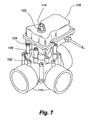
- FIG. 7 is a perspective view of the diverter valve of FIG. 1 with an actuator positioned on the lid.
- FIG. 8 is a perspective view of an alternate embodiment of the lid portion and stop members for use with a diverter valve, such as the diverter valve of FIG. 1 .
- FIG. 9 is a perspective view of another alternate embodiment of the lid portion and stop member for use with a diverter valve, such as the diverter valve of FIG. 1 .
- FIG. 10 is a partial cross-section view of the lid portion and stop member of FIG. 9 , taken along line 10 - 10 in FIG. 9 .
- FIG. 11 is a perspective view of a closure member for a diverter valve, such as the diverter valve of FIG. 1 .
- FIG. 12 is a perspective view of the retainer plate for the closure member of FIG. 11 .
- FIG. 13 is a perspective view of an embodiment of a stop member for a diverter valve, such as the diverter valve of FIG. 1 .
- FIG. 14 is a perspective view of another embodiment of a stop member for a diverter valve, such as the diverter valve of FIG. 1 .
- FIG. 15 is another perspective view of the stop member of FIG. 14 .
- the diverter valve may take the form of a body portion joined to a lid portion to define a fluid chamber. Two or more pipe connectors may extend from the body portion to fluidly connect the diverter valve's fluid chamber to piping in a fluid system.
- a closure member may be received in the fluid chamber.
- a movable member, actuator, or other movable member may be connected to the closure member. The movable member, actuator or other movable member may be movable relative to the lid portion to selectively reposition the closure member in the fluid chamber to close a fluid opening in the body portion fluidly connecting a pipe connector fluid passage to the fluid chamber.
- the lid portion may include stops, either permanently or removably attached to the lid portion, to limit movement of the movable member relative to the lid portion.
- the stops may be arranged relative to the closure member and the body portion to prevent the movable member from being moved to a position that closes certain fluid openings in the body portion.
- a repositionable stop member may be positioned between the stops to further limit movement of the movable member relative to the lid portion. In particular, movement of the movable member relative to the lid portion may be limited to movement between the repositionable stop member and one of the stops.
- the lid portion may take the form of a lid.
- the lid may include a lid body defining two sets of apertures. One set of apertures may receive fasteners for joining the lid to the body portion. The other set of apertures may receive fasteners for joining an actuator to the lid.
- the lid body may further include hollow columns extending from an upper surface of the lid body. The apertures for joining the actuator to the lid may be located in these hollow columns.
- FIGS. 1 and 2 depict an embodiment of a diverter valve 100 for use in fluid conveyance system, such as a pool piping system.
- the diverter valve 100 may include a generally dome shaped lid or cover portion 102 removably joined to a generally cylindrical body portion 104 by fasteners 106 received in lid and body apertures defined in the lid portion 102 and the body portion 104 , respectively.
- the dome-shaped lid portion 102 enhances the structural strength of the lid portion 102 , especially when covering a relatively large top opening in the body portion.
- the lid portion 102 may be a more planar shape or any other desired shape to cover the top opening in the body portion 104 .
- the lid portion 102 and the body portion 104 may define a fluid chamber for receiving and redirecting fluid in a fluid system connected to the diverter valve 100 .
- a user may access the interior of the diverter valve 100 for cleaning and maintaining the fluid chamber and/or the various components contained within the fluid chamber.
- a removable lid portion 102 may also provide interchangeability between lid and body portions 102 , 104 , may provide flexibility in changing which fluid passages may be selectively closed by a closure member received within the fluid chamber, and may facilitate assembly of the diverter valve 100 .
- the lid portion 102 may be permanently joined to the body portion 104 , or the lid portion 102 and the body portion 104 may be formed as an integral piece.
- Two or more cylindrical pipe connectors 108 may extend from the body portion 104 .
- typically three pipe connectors 108 extend from the body portion 104 as shown in FIGS. 1 and 2 . In other embodiments, however, more or less than three pipe connectors 108 may extend from the body portion 104 .
- the pipe connectors 108 are depicted as being cylindrical, the pipe connectors 108 may be formed into any desired shape.
- Each pipe connector 108 may define a port or an opening 110 , and a fluid passage, for fluidly joining the fluid chamber to pipes or the like joined to the pipe connectors 108 .
- Fluid communication between a pipe connector fluid passage and the fluid chamber may be selectively enabled or disabled to control which portions of a fluid system deliver or receive fluid to or from the diverter valve 100 .
- the diverter valve 100 may further include a movable member 112 , such as a handle, operatively associated with a closure member 114 ( FIG. 3B ) and selectively rotatable relative to the lid portion 102 .
- Rotating the movable member 112 relative to the lid portion 102 may selectively close fluid communication between the fluid chamber 116 and a pipe connector fluid passage 118 by placing a portion of the closure member 114 between the fluid passage 118 and the fluid chamber 116 as shown in FIG. 4 .
- the handle may be replaced with an actuator 120 , which may be selectively activated to open or close fluid communication between a fluid passage 118 and the fluid chamber 116 .
- the actuator 120 may be operatively associated with the closure member 114 via coupling to a closure member connection shaft 122 and joined to the lid portion 102 by fasteners 124 received in actuator fastener apertures 126 (see, e.g., FIG. 1 ) defined by cylindrical lid aperture columns 128 extending from an upper surface of the lid portion 102 .
- the actuator fastener apertures 126 may be threaded or unthreaded depending upon the type of fastener used.
- the actuator fastener apertures 126 may be threaded when receiving a threaded fastener, such as a threaded screw.
- the actuator fastener apertures 126 may be unthreaded when receiving a fastener that does not require preformed threads, such as a self tapping screw.
- left and right stops 130 , 132 may extend from the lid portion 102 to limit the range of rotation of the movable member 112 relative to the lid portion 102 . Limiting the movable member's range of rotation may prevent the movable member 112 from being moved into a position relative to the lid portion 102 that closes fluid communication between a certain fluid passage 118 , or passages, and the fluid chamber 116 . For example, fluid communication between the fluid chamber 116 and a fluid passage 118 fluidly connected to a pool pump should generally not be disabled because such closure may damage the pump and/or the piping connected to the pump.
- the stops 130 , 132 may be positioned relative to a fluid passage to prevent the movable member 112 from being inadvertently rotated or pivoted into a position relative to the lid portion 102 that closes fluid communication between the fluid chamber 116 and the fluid passage 118 fluidly connected to the pool pump.
- Each stop 130 , 132 may take the form of a curved wall as shown in FIG. 1 , or may take the form of any desired shape that engages the movable member 112 to limit further movement of the movable member 112 relative to the lid portion 102 .
- Movement of the movable member 112 between the stops 130 , 132 may be further limited by a movable stop member assembly 134 operatively associated with the lid portion 102 .
- the movable stop member assembly 134 may take the form of a movable or repositionable stop member 136 , such as an index tab as shown in FIG. 2 or a slider as shown in FIG. 9 , movably associated with the lid portion 102 by a movable member guide structure 138 , such as an indexing wall as shown in FIG. 2 or a track or rail as shown in FIG. 9 .
- the movable stop member 136 may be readily removable from the movable member guide structure 138 , or may be semi-permanently or permanently joined, or otherwise associated with, the movable member guide structure 138 .
- the movable stop member 136 and the movable member guide structure 138 may take the form of an index tab and an indexing wall.
- the indexing wall, or other engagement member, as depicted in FIGS. 1 and 2 may take the form of a curved wall extending from the lid portion 102 between the stops 130 , 132 and having multiple vertical splines or teeth for engaging the index tab.
- the index tab may be positioned at multiple locations along the indexing wall using the multiple vertical splines or teeth, thus providing for multiple positions of the index tab relative to the stops 130 , 132 .
- the index tab may be placed approximately half-way between the stops 130 , 132 . In the example shown in FIG.
- the movable member 112 may be rotated between the right stop 132 and the index tab.
- the index tab may be disengaged from the indexing wall, the movable member 112 rotated proximate the left stop 130 , and the index member re-engaged with the indexing wall such that the movable member 112 may be rotated only between the left stop 130 and the index tab.
- the index tab may be positioned at other locations along the indexing wall to increase or decrease the range of rotation between one of the stops 130 , 132 and the index tab.
- the indexing wall, or other movable member guide structure 138 may partially encircle a central area of the lid portion 102 as shown in FIGS. 1 and 2 , or may completely encircle a central area of the lid portion 102 as shown in FIG. 8 .
- movable stop members 136 such as index tabs, may be substituted for the left and right stops 130 , 132 shown in the FIGS. 1 and 2 to provide more flexibility in setting the maximum desired rotational range for the movable member 112 relative to the lid portion 102 . For example, as shown in FIG.
- the left and right stops 130 , 132 are each replaced by a movable stop member 136 to set the maximum range of rotation for the movable member 112 relative to the lid portion 102 .
- both stops 130 , 132 are shown in FIG. 8 as replaced by a movable stop member 136 , only one stop may be replaced by a movable stop member 136 , if desired.
- FIG. 9 depicts yet another embodiment of a movable stop member assembly 134 .
- the movable stop member 136 may take the form of a slider movably deposed on a movable member guide structure or other engagement member, such as a rail.
- the slider may be joined, either permanently or removably, to the rail or track.
- the slider may be repositioned relative to the lid portion 102 by sliding it along the rail or track.
- the slider may include a plunger 140 biased downwardly by a spring 142 to engage detents 144 formed in the lid portion 102 to maintain the position of the slider relative to the lid portion 102 once moved into a select and desired position relative to the lid portion 102 .
- rotation or other movement of the movable member 112 relative to the lid portion 102 may be selectively disabled by a lock fastener 150 operatively associated with the movable member 112 .
- the lock fastener 150 may be selectively moved relative to movable member 112 to lock and unlock the movable member 112 to and from the lid portion 102 .
- rotation or other movement of the movable member 112 relative to the lid portion 102 is prevented or otherwise restricted.
- FIGS. 3A and 3B depict an exploded view of the diverter valve 100 of FIG. 1
- FIGS. 4 and 5 depict cross-sectional views of the diverter valve 100 of FIG. 1
- the body portion 104 may include a body portion bottom 160 ( FIG. 4 ), a body portion interior surface 162 , and a body portion exterior surface 164 .
- Hollow fastener columns 166 arranged around the perimeter of the body portion 104 and extending from the body portion exterior surface 164 may define body portion apertures 168 for receiving fasteners 106 to join the body portion 104 to the lid portion 102 as described in more detail below. Eight such fastener columns 166 are shown in FIG. 3B .
- more or less than eight fastener columns may be formed on the body portion 104 .
- the body portion interior surface 162 , the body portion bottom 160 , and the lid portion 102 may define a generally cylindrical fluid chamber 116 .
- Body portion fluid openings 170 defined in the body portion 104 and co-axially aligned with the fluid passages 118 provide fluid communication between the fluid passages 118 and the fluid chamber 116 .
- the closure member 114 may be movably received within the fluid chamber 116 to selectively cover, in whole or in part, one or more of the body portion fluid openings 170 . Complete coverage of a body portion fluid opening 170 by the closure member 114 ends fluid communication between the associated fluid passage 118 and the fluid chamber 116 . To completely cover a body portion fluid opening 170 , the closure member 114 may be rotated, pivoted, or otherwise moved relative to the body portion 104 until a closure plug 172 of the closure member 114 covers the body portion fluid opening 170 . Generally, the closure plug 172 may be sized to be at least slightly larger than the largest body portion fluid opening 170 . Further, the closure plug outer surface 174 may be arcuate or convex shaped to match the generally curved interior surface 162 of the body portion 104 .
- upper and lower closure member arms 176 , 178 may extend radially away from the closure plug 176 .
- a generally cylindrical closure member bearing shaft or axle 180 may extend generally downward from the lower closure member arm 178 for receipt in a bearing hole 182 defined in the body portion bottom 160 of the body portion 104 .
- the closure member bearing shaft 180 may be sized to be snugly, but rotatably or pivotally received within the bearing hole 182 .
- a generally cylindrical closure member connection shaft or axle 184 may extend generally upward from the upper closure member arm 176 .
- the closure member connection shaft 184 may extend above the lid portion 102 through a lid portion shaft opening 186 .
- the closure member connection shaft 184 may be connected to a movable member 112 , such as a handle, an actuator or other device, for rotating, pivoting or otherwise moving the closure member 114 from outside the body portion 104 .
- the closure member connection shaft 184 may include connection slots 188 for receiving projections 190 extending inwardly from a movable member shaft opening 192 to join the movable member 112 to the closure member 114 .
- This connection arrangement allows the movable member 112 to be slid or moved relative to the longitudinal axis of the closure member connection shaft 184 while also transferring rotation of the movable member 112 about the longitudinal axis of the closure member connection shaft 184 to the closure member 114 .
- the connection slots 188 may receive projections 190 formed in another structure or device, such as the actuator shown in FIG. 7 .
- the closure member 114 may include a valve seal 200 to prevent fluid leakage between a closed fluid passage 118 and the fluid chamber 116 .
- the valve seal 200 may be joined to the closure plug 172 by a retainer plate 202 .
- the retainer plate 202 may include one or more retainer plate pegs sized for receipt in closure plug holes formed in the closure plug 172 .
- the retainer plate pegs may be retained within the closure plug holes 204 by press fit, adhesives, mechanical fasteners, heat or sonic welding, any other known joining method, or any combination thereof.
- the retainer plate outer surface may be arcuate or convex shaped to match the generally cylindrical interior shape of the body portion 104 .
- the valve seal 200 may include a valve seal body defining a valve seal opening 210 .
- the valve opening 210 reduces the amount of material used to form the valve seal 200 .
- the valve opening 210 also enables bending of the generally rectangular valve seal body into an arcuate or convex shape conforming to the arcuate or convex shape of the closure plug 172 .
- Outer valve seal flanges 212 may extend outwardly from the left and right sides of the valve seal body for receipt within closure plug slots 214 formed on left and rights sides of the closure plug 172 . Receipt of the outer valve seal flanges 212 within the closure plug slots 214 temporarily joins the valve seal 200 to the closure plug 172 prior to joining the retainer plate 202 to the closure plug 172 .
- Inner valve seal flanges 216 may extend inwardly around the perimeter of the valve sealing opening 210 .
- the inner valve seal flanges 216 are positioned between the closure plug 172 and the retainer plate 202 , thus maintaining the connection of the valve seal 200 to the closure plug 172 upon joining the retainer plate 202 to the closure plug 172 .
- the valve seal 200 may form a water-tight seal between the closure member 114 and the body portion 104 around a closed fluid opening 170 to prevent fluid from passing moving between the closed fluid passage 118 and the fluid chamber 116 through the joint formed between the body portion 104 and the closure member 114 .
- the valve seal 200 may be composed of rubber or other resilient, sealing material.
- One or more shaft O-rings 218 may be received on the closure member connection shaft 184 . As shown in FIG. 5 , the shaft O-rings 218 may prevent fluid leakage from the fluid chamber 116 along the longitudinal joint formed between the closure member 114 and the lid portion 102 . With reference FIGS. 3A and 5 , a body portion O-ring 220 may rest on an O-ring surface formed by stepping an upper portion of the body portion interior surface 162 . The body portion O-ring 218 may prevent fluid leakage from the fluid chamber 116 along the radially extending joint formed between the body portion 104 and the lid portion 102 . The shaft and body portion O-rings 218 , 220 may be formed from rubber, or any other resilient, sealing material.
- the lid portion 102 may include a lid 230 removably attachable to the body portion 104 .
- Winged sections 232 may extend radially outward from the perimeter of the lid 230 to define lid apertures 234 for receiving fasteners 106 to join the lid 230 to the body portion 104 .
- Eight such lid apertures are depicted in FIG. 3A . In other embodiments, more or less than eight lid apertures may be defined by the lid.
- the lid 230 may be placed on the body portion 104 to align the body portion apertures 168 with the lid apertures 234 . Fasteners 106 received within the aligned body portion and lid apertures 168 , 234 join the lid 230 to the body portion 204 .
- the body portion and lid apertures 168 , 234 may be threaded or unthreaded. Further, the lid 230 may be removably or permanently joined to the body portion 104 by other joining methods, such as clamping, press fitting, heat or sonic welding, adhering, and so on.
- a hollow cylindrical lid collar 240 may extend upwardly from a dome shaped lid body.
- the lid collar 240 may define a segment of the lid portion shaft opening 186 defined in the lid portion 102
- the dome shaped lid body may define another segment of the lid portion shaft opening 186 .
- the lid collar 240 may include an engagement member, such as multiple lid teeth, for engagement with a corresponding engagement member, such as multiple handle teeth formed on the movable member 112 .
- the lid and handle teeth prevent, or otherwise resist, rotation of the movable member 112 relative to the lid portion 102 .
- a user may selectively engage and disengage the lid and movable member teeth with aid of the lock fastener 150 as described in more detail below, thus selectively allowing and resisting movement of the movable member 112 relative to the lid portion 102 .
- one or more generally rectangular areas 250 of the lid body may be depressed in the outer surface for receiving removable signs (not shown).
- the signs may be joined to the lid body using fasteners received in sign holes 252 formed in the lid body.
- the signs may be printed with information regarding the diverter valve, or the piping system joined to the diverter valve, such as whether the pipe connector aligned with the depressed area is an inlet or and outlet, or whether the piping joined to the pipe connector is attached to a pump, a filter, and so on.
- the movable member 112 may include a lever portion 254 and a locator portion 256 extending from the lever portion 254 .
- the lever portion 254 may define the movable member shaft opening 192 and may include a lever extending generally upwardly from the movable member shaft opening 192 for a first segment of the lever portion 254 and then generally horizontally away from the movable member shaft opening 192 for a second segment of the lever portion 254 . Slightly extending the lever upwardly before extending the lever horizontally away from the movable member shaft opening 192 provides additional space between the lid portion 102 and the movable member 112 for a user to insert the user's fingers when grasping the movable member 112 .
- the locator portion 256 may extend away from the movable member shaft opening 192 in a direction generally diametrically opposite the lever portion 254 .
- the locator portion 256 may be pie shaped with an arcuate perimeter. The length of the arcuate perimeter may generally match the arcuate width of the closure plug 172 , thus providing a visual indication to the user of the approximate position of the closure plug 172 within the fluid chamber 116 for certain configuration of the movable member 112 relative to the closure member 114 . Specifically, when the movable member and closure member 114 are joined such that the locator portion 256 aligns over the closure plug 172 , then the locator portion 256 provides a visual indication of the location of the closure plug 172 within the fluid chamber 116 .
- connection slots 188 in the closure member 114 and the corresponding projection 190 in the movable member may be different than the other connection slots 188 and corresponding projections 190 (for example, shallower, deeper, wider, etc.) to allow the movable member 112 and closure member 114 to be joined in only one or a limited number of possible orientations.
- the foregoing example is merely illustrative of one method to key the movable member 112 and the closure member 114 and is not intended to limit use of other keying methods.
- the lock fastener 150 may include a cylindrical and threaded lock fastener shaft 260 extending downwardly from a dome shaped lock fastener bearing portion 262 , and a lock fastener grasping portion 264 extending upwardly from the lock fastener bearing portion 262 .
- the lock fastener shaft 260 may be threaded partially along the length of the shaft 260 as shown in FIG. 3A , or may be threaded along substantially the entire length of the shaft 260 .
- the lock fastener shaft 260 may be threadedly received within a lock fastener aperture 266 defined in the closure member connection shaft 184 .
- a user may use the lock fastener 150 to selectively permit and resist movement of the movable member 112 relative to the lid portion 102 . More particularly, the user may tighten the lock fastener 150 against the movable member 112 to cause the movable member 112 to move downwardly towards the lid portion 102 until the movable member and lid teeth engage, thus preventing or otherwise resisting rotation or other movement of the movable member 112 relative to the lid portion 102 . The user may then loosen the lock fastener 150 to allow the movable member 112 to be slid upwardly along the closure member connection shaft 184 to disengage the lid and handle teeth, thus allowing the user to rotate, pivot, or otherwise move the movable member 112 relative to the lid portion 102 .
- the user may again tighten the lock fastener 150 to prevent or otherwise resist movement of the movable member 112 relative to the lid portion 102 .
- one or more of the fluid passages defined by the pipe connectors 108 may be sized slightly larger than the body portion fluid openings 170 , thus forming an annular interior surface or edge proximate the transition from the pipe connector fluid passage 118 to the body portion fluid opening 170 .
- An annular recess or groove 270 may be defined within the interior surface for receiving PVC glue, or other adhesive, to join a pipe received within the pipe connector 108 to the diverter valve 100 .
- the annular groove 270 for receiving glue may limit the adhesive from entering into the body portion fluid opening 170 when joining a pipe to the diverter valve 100 .
- FIG. 6 depicts a partial elevation view of the diverter valve 100 showing engagement of the movable member 112 with the movable stop member 136 .
- the movable member 112 may include a handle stop 280 extending downwardly from the locator portion 256 of the movable member 112 .
- the handle stop 280 may engage the movable stop member 136 , thus limiting further rotation or movement of the movable member 112 relative to the lid portion 102 in a direction towards the movable stop member 136 .
- the handle stop 280 may engage one of the stops 130 , 132 on the lid portion 102 , thus limiting further rotation or movement of the movable member 112 relative to the lid portion 102 in a direction towards the stop.
- FIG. 11 depicts a perspective view of the closure member 114 .
- the rear or inwardly facing surface of the closure plug 172 may be ribbed to reduce to weight and/or the amount of material used to form the closure plug 172 while maintaining the closure plug's structural strength.
- the upper and lower closure member arms 176 , 178 may be ribbed to reduce the weight and/or the amount of material used to form the arms 176 , 178 while maintaining the structural strength of the arms 176 , 178 .
- FIG. 12 depicts a perspective view of the retainer plate 202 showing the pegs 282 for joining the retainer plate 202 to the closure plug 172 .
- FIG. 13 depicts a perspective view of an embodiment of the movable stop member 136 .
- the movable stop member 136 may include a stop member connection portion 290 formed into a U or C-shape. An upper portion of the stop member connection portion 290 may step inwardly to define an upper surface for engagement with the handle stop on the movable member 112 .
- Spline engagement members 292 may extend inwardly from the opposing sides of the U or C-shaped portion of the stop member connection portion 290 for receipt between the vertical splines or teeth on the indexing wall, thus joining the movable stop member 136 to the indexing wall.
- a finger or hand grasping tab 294 may extend horizontally away from the stop member connection portion 290 to provide an element for a user to hold when positioning the movable stop member 136 on the indexing wall.
- FIGS. 14 and 15 depict perspective views of another embodiment of the movable stop member 136 .
- This embodiment is similar to the embodiment depicted in FIG. 13 except the movable stop member 136 further includes a ring 296 joined to the stop member connection portion 290 by a strap or elongated member 298 .
- the ring 296 may be received on the lid portion collar 240 to rotatably join the stop member 136 to the lid portion 102 .
- the ring 296 allows the stop member 136 to be rotated or pivoted around the lid portion collar 240 to position in the stop member 136 at another location relative to the lid portion 102 while keeping the stop member 136 joined to the lid portion 102 .
- Such joining of the stop member 136 to the lid portion 102 may help to keep the stop member 136 , which may be a relatively small piece, from being misplaced when not joined to the indexing wall.
- the components of the diverter valve described herein including the lid portion, the body portion, movable member (e.g. a handle), the lock fastener, the fasteners, and so on, may be composed of any suitable material, including, but not limited to, plastic (e.g., PVC), metal, alloy, rubber, and so on. Any of the components may be formed from a single part, or may be formed from multiple parts joined together to create the component.
- plastic e.g., PVC
- metal e.g., metal, alloy, rubber, and so on.
- Any of the components may be formed from a single part, or may be formed from multiple parts joined together to create the component.
Abstract
Description
Claims (21)
Priority Applications (1)
| Application Number | Priority Date | Filing Date | Title |
|---|---|---|---|
| US12/966,792 US8910662B2 (en) | 2007-03-01 | 2010-12-13 | Diverter valve |
Applications Claiming Priority (2)
| Application Number | Priority Date | Filing Date | Title |
|---|---|---|---|
| US11/681,015 US7849877B2 (en) | 2007-03-01 | 2007-03-01 | Diverter valve |
| US12/966,792 US8910662B2 (en) | 2007-03-01 | 2010-12-13 | Diverter valve |
Related Parent Applications (1)
| Application Number | Title | Priority Date | Filing Date |
|---|---|---|---|
| US11/681,015 Continuation US7849877B2 (en) | 2007-03-01 | 2007-03-01 | Diverter valve |
Publications (2)
| Publication Number | Publication Date |
|---|---|
| US20110089357A1 US20110089357A1 (en) | 2011-04-21 |
| US8910662B2 true US8910662B2 (en) | 2014-12-16 |
Family
ID=39732263
Family Applications (2)
| Application Number | Title | Priority Date | Filing Date |
|---|---|---|---|
| US11/681,015 Active 2029-08-19 US7849877B2 (en) | 2007-03-01 | 2007-03-01 | Diverter valve |
| US12/966,792 Active 2028-10-21 US8910662B2 (en) | 2007-03-01 | 2010-12-13 | Diverter valve |
Family Applications Before (1)
| Application Number | Title | Priority Date | Filing Date |
|---|---|---|---|
| US11/681,015 Active 2029-08-19 US7849877B2 (en) | 2007-03-01 | 2007-03-01 | Diverter valve |
Country Status (3)
| Country | Link |
|---|---|
| US (2) | US7849877B2 (en) |
| CA (1) | CA2679668C (en) |
| WO (1) | WO2008109293A1 (en) |
Cited By (3)
| Publication number | Priority date | Publication date | Assignee | Title |
|---|---|---|---|---|
| US20150048036A1 (en) * | 2013-08-16 | 2015-02-19 | Robert Stanley Chick | Self cleaning swimming pool filter |
| US20170067568A1 (en) * | 2015-09-08 | 2017-03-09 | David R. Duncan | Stopcock with detents |
| US11118694B2 (en) | 2020-01-30 | 2021-09-14 | Brasscraft Manufacturing Company | Multiple outlet valve assembly |
Families Citing this family (56)
| Publication number | Priority date | Publication date | Assignee | Title |
|---|---|---|---|---|
| US7448653B2 (en) | 2005-06-10 | 2008-11-11 | Value Plastics, Inc. | Female connector for releasable coupling with a male connector defining a fluid conduit |
| US7806139B2 (en) | 2006-01-20 | 2010-10-05 | Value Plastics, Inc. | Fluid conduit coupling assembly having male and female couplers with integral valves |
| US7849877B2 (en) | 2007-03-01 | 2010-12-14 | Zodiac Pool Systems, Inc. | Diverter valve |
| US7967005B2 (en) * | 2007-04-13 | 2011-06-28 | Daniel Parrish | Dual fuel gas valve and gas grill |
| US8082951B2 (en) * | 2007-10-10 | 2011-12-27 | Pentair Water Pool And Spa, Inc. | Diverter valve apparatus and method |
| USD654573S1 (en) | 2007-11-19 | 2012-02-21 | Value Plastics, Inc. | Female quick connect fitting |
| US8235426B2 (en) | 2008-07-03 | 2012-08-07 | Nordson Corporation | Latch assembly for joining two conduits |
| USD655393S1 (en) * | 2009-06-23 | 2012-03-06 | Value Plastics, Inc. | Multi-port valve |
| USD650478S1 (en) | 2009-12-23 | 2011-12-13 | Value Plastics, Inc. | Female dual lumen connector |
| USD783815S1 (en) | 2009-12-09 | 2017-04-11 | General Electric Company | Male dual lumen bayonet connector |
| USD649240S1 (en) | 2009-12-09 | 2011-11-22 | Value Plastics, Inc. | Male dual lumen bayonet connector |
| US10711930B2 (en) | 2009-12-09 | 2020-07-14 | Nordson Corporation | Releasable connection assembly |
| US9388929B2 (en) | 2009-12-09 | 2016-07-12 | Nordson Corporation | Male bayonet connector |
| KR101762427B1 (en) | 2009-12-23 | 2017-07-28 | 제너럴 일렉트릭 캄파니 | Button latch with integrally molded cantilever springs |
| KR101715636B1 (en) | 2009-12-23 | 2017-03-13 | 노드슨 코포레이션 | Fluid connector latches with profile lead-ins |
| CN102573390A (en) * | 2010-12-23 | 2012-07-11 | 鸿富锦精密工业(深圳)有限公司 | Cooling system |
| USD652510S1 (en) | 2011-02-11 | 2012-01-17 | Value Plastics, Inc. | Connector for fluid tubing |
| USD652511S1 (en) | 2011-02-11 | 2012-01-17 | Value Plastics, Inc. | Female body of connector for fluid tubing |
| USD663022S1 (en) | 2011-02-11 | 2012-07-03 | Nordson Corporation | Male body of connector for fluid tubing |
| US9464722B2 (en) * | 2011-07-08 | 2016-10-11 | Basf Se | Pipe switch with metering function |
| USD699841S1 (en) | 2011-07-29 | 2014-02-18 | Nordson Corporation | Female body of connector for fluid tubing |
| USD699840S1 (en) | 2011-07-29 | 2014-02-18 | Nordson Corporation | Male body of connector for fluid tubing |
| USD698440S1 (en) | 2011-07-29 | 2014-01-28 | Nordson Corporation | Connector for fluid tubing |
| US8863738B2 (en) * | 2011-10-17 | 2014-10-21 | Donald C. Symonds | Pool heating device system |
| USD709612S1 (en) | 2011-12-23 | 2014-07-22 | Nordson Corporation | Female dual lumen connector |
| CA3031929C (en) * | 2012-01-09 | 2021-05-11 | Cnh Industrial Canada, Ltd. | Rotary flow divider assembly for agricultural product distribution system |
| US20130228247A1 (en) * | 2012-03-02 | 2013-09-05 | Hans D. Baumann | Canted, single vane, three-way butterfly valve |
| GB2502095B (en) * | 2012-05-15 | 2020-06-03 | Leonard Crossley Hugh | A compact economical valve for user controlled redirection of flow in water saving or recycling systems |
| JP5914176B2 (en) * | 2012-05-31 | 2016-05-11 | 株式会社ミクニ | Rotary valve |
| JP5682598B2 (en) * | 2012-07-30 | 2015-03-11 | 株式会社デンソー | Range switching device |
| USD735769S1 (en) * | 2013-01-10 | 2015-08-04 | Cnh Industrial Canada Ltd. | Rotary flow divider for seeding and planting implements |
| US9429958B2 (en) * | 2013-08-05 | 2016-08-30 | Taikoh Co., Ltd. | Regulator unit |
| PT2837862T (en) * | 2013-08-12 | 2018-02-15 | Ingevert 2000 S L | A valve having an opening or closure limiting device |
| CN103615574B (en) * | 2013-11-29 | 2016-06-15 | 中国铁建重工集团有限公司 | Change-over valve device |
| JP5946547B2 (en) | 2014-05-29 | 2016-07-06 | 麓技研株式会社 | On / off valve for abnormal liquid |
| DE102014110706A1 (en) * | 2014-07-29 | 2016-02-18 | Mahle International Gmbh | Valve |
| JP6143312B2 (en) | 2015-08-09 | 2017-06-07 | 麓技研株式会社 | On-off valve |
| USD783778S1 (en) | 2015-09-18 | 2017-04-11 | Fumoto Giken Co., Ltd. | Valve for oil change or the like |
| USD783777S1 (en) | 2015-09-18 | 2017-04-11 | Fumoto Giken Co., Ltd. | Valve for oil change or the like |
| USD790040S1 (en) | 2015-12-11 | 2017-06-20 | Fumoto Giken Co., Ltd. | Valve for oil change or the like |
| GB2546322A (en) * | 2016-01-15 | 2017-07-19 | Singh Bath Charanjit | A device for flushing a system |
| JP1565312S (en) | 2016-03-08 | 2016-12-12 | ||
| JP6620680B2 (en) * | 2016-06-17 | 2019-12-18 | 株式会社デンソー | Flow path switching valve |
| USD838366S1 (en) | 2016-10-31 | 2019-01-15 | Nordson Corporation | Blood pressure connector |
| US10358222B2 (en) * | 2016-12-12 | 2019-07-23 | Hamilton Sundstrand Corporation | Air cycle machine module air gate seal for environmental control systems |
| US20190177955A1 (en) * | 2017-12-08 | 2019-06-13 | Prestigious Innovations, LLC | Hydrostatic pressure washer |
| KR102044025B1 (en) * | 2018-02-13 | 2019-11-12 | 주식회사 디에이치콘트롤스 | 3-Way electronic valve with the function of the high performance of flow rate |
| KR102044091B1 (en) * | 2018-03-14 | 2019-11-12 | 진종근 | 3-Way electronic valve with the function of the high performance of flow rate |
| US11193599B2 (en) | 2018-05-11 | 2021-12-07 | Oxyswitch, Llc | Flowmeter bi-valve |
| CN108708992A (en) * | 2018-08-07 | 2018-10-26 | 台州力和环保科技有限公司 | A kind of spool |
| USD845438S1 (en) * | 2018-09-18 | 2019-04-09 | Oxyswitch Llc | Bi-valve |
| GB2586837B (en) * | 2019-09-05 | 2023-09-06 | Aalberts Integrated Piping Systems Ltd | Plumbing Fitting with Movable Cavity Containing a Mechanism |
| RU198818U1 (en) * | 2020-04-19 | 2020-07-29 | Закрытое акционерное общество "ИТОМАК" | FLOW SWITCH |
| CN112156259B (en) * | 2020-10-12 | 2022-05-03 | 江苏科凌医疗器械有限公司 | Air pump type automatic gastric lavage machine |
| FR3119656B1 (en) * | 2021-02-05 | 2023-11-17 | Bontaz Centre R & D | ROTARY HYDRAULIC DISTRIBUTOR WITH SIMPLIFIED MANUFACTURING |
| US11464214B1 (en) * | 2021-03-23 | 2022-10-11 | Navpreet Singh Sethi | Periodic and automated water change device having a configurable water change schedule |
Citations (197)
| Publication number | Priority date | Publication date | Assignee | Title |
|---|---|---|---|---|
| US261068A (en) | 1882-07-11 | Emile m | ||
| US413671A (en) | 1889-10-29 | jewell | ||
| US755370A (en) | 1902-08-04 | 1904-03-22 | Charles Kessler | Mouthpiece for pipes or cigar-holders. |
| US825706A (en) | 1903-08-07 | 1906-07-10 | Julius A Dyblie | Valve mechanism. |
| US860672A (en) | 1905-05-25 | 1907-07-23 | James B Ladd | Reversing-valve. |
| US1008097A (en) | 1911-06-03 | 1911-11-07 | John Joseph Winnow | Valve. |
| US1104918A (en) | 1913-09-25 | 1914-07-28 | Thomas G Mouat | Valve. |
| US1116584A (en) | 1914-01-14 | 1914-11-10 | Elva C Gingrich | Spark-plug. |
| US1130989A (en) | 1914-05-12 | 1915-03-09 | Thomas K Lemon | Valve. |
| US1166571A (en) | 1911-01-13 | 1916-01-04 | Barco Brass & Joint Company | Valve device. |
| US1244552A (en) | 1916-05-05 | 1917-10-30 | Internat Filler Corp | Overflow jar or trap. |
| US1270722A (en) | 1918-02-02 | 1918-06-25 | Isaac W Gillette | Valve for train-pipes. |
| US1315741A (en) | 1919-09-09 | Gsaduate-contbol | ||
| US1554470A (en) | 1921-04-04 | 1925-09-22 | Trumble Gas Trap Co | Valve |
| FR660909A (en) | 1928-01-04 | 1929-07-18 | Ehrhardt & Sehmer Ag | Safety valve for high pressures |
| US1985192A (en) | 1932-03-15 | 1934-12-18 | O'marra Martin | Spark plug |
| US2114482A (en) | 1936-12-08 | 1938-04-19 | Frank Bartz | Closure for containers |
| US2137406A (en) | 1936-12-08 | 1938-11-22 | Puritan Engineering Corp | Water softener valve |
| US2145132A (en) | 1935-09-10 | 1939-01-24 | Phillips Petroleum Co | Apparatus for blending liquids |
| US2253020A (en) | 1938-01-29 | 1941-08-19 | Lee G Daniels | Valve structure |
| US2275132A (en) | 1940-08-03 | 1942-03-03 | C A Dunham Co | Discharge valve |
| US2339101A (en) | 1941-03-13 | 1944-01-11 | Arthur L Parker | Check valve assembly |
| US2345306A (en) | 1942-02-24 | 1944-03-28 | Adel Prec Products Corp | Fluid controlled valve |
| FR921787A (en) | 1945-11-29 | 1947-05-19 | Valve lift and return control mode | |
| US2462348A (en) | 1944-03-24 | 1949-02-22 | Batchler Roy | Pipe joint |
| GB622502A (en) | 1946-12-12 | 1949-05-03 | Milton Antiseptic Ltd | Improvements in or relating to small non-return valves |
| US2589176A (en) | 1946-04-11 | 1952-03-11 | Wheatley Thomas | Valve assembly |
| US2598148A (en) | 1948-07-28 | 1952-05-27 | H A Thrush & Company | Diverter valve |
| GB682591A (en) | 1949-07-18 | 1952-11-12 | Frank Christopher Potts | Valve structure |
| US2662549A (en) | 1949-05-02 | 1953-12-15 | Belco Ind Equipment Division I | Multiport valve |
| US2708096A (en) | 1951-10-23 | 1955-05-10 | Mueller Co | Valve devices |
| US2766771A (en) | 1952-03-03 | 1956-10-16 | Honeywell Regulator Co | Control valve |
| US2825587A (en) | 1954-11-03 | 1958-03-04 | Plymouth Ind Products Inc | Pipe-in-socket coupling for slotted end conduits |
| US2829668A (en) | 1954-05-13 | 1958-04-08 | Mueller Co | Lubricated rotary plug valve |
| US2839082A (en) | 1956-03-09 | 1958-06-17 | Vapor Heating Corp | Train line end valve |
| US2889990A (en) | 1957-03-20 | 1959-06-09 | Honeywell Regulator Co | Thermostatic valve |
| US3072379A (en) | 1958-08-04 | 1963-01-08 | Fmc Corp | Rotary valve having segmental seat inserts and a resilient retaining sleeve |
| US3075547A (en) | 1960-04-22 | 1963-01-29 | Scaramucci Domer | Swing check valve |
| FR1329057A (en) | 1962-04-27 | 1963-06-07 | Multi-way valve | |
| US3166499A (en) | 1960-10-26 | 1965-01-19 | Bruner Corp | Ion exchange water softening system |
| US3195726A (en) | 1962-06-18 | 1965-07-20 | Saurenman Co Inc | Control valve means for swimming pool filter and backwash operations |
| US3233865A (en) | 1960-11-04 | 1966-02-08 | Ajem Lab Inc | Rotary plug valve |
| US3365064A (en) | 1965-10-14 | 1968-01-23 | Jacuzzi Bros Inc | Swimming pool system and backwash assembly therefor |
| US3392738A (en) | 1967-07-26 | 1968-07-16 | Andrew L. Pansini | Automatic cleaner for swimming pools |
| US3403700A (en) | 1966-05-09 | 1968-10-01 | Meynell & Sons Ltd | Fluid mixing valve with adjustable cam actuator |
| US3471021A (en) | 1966-02-07 | 1969-10-07 | Swimquip Inc | Valve and liquid flow system |
| US3476057A (en) | 1967-09-08 | 1969-11-04 | Philip W Mcelroy | Aggregate pumping apparatus |
| US3489178A (en) | 1966-03-11 | 1970-01-13 | K B Engineering Co | Diverter valve |
| US3499467A (en) | 1967-04-12 | 1970-03-10 | Lunkenheimer Co | Multiple flow-pattern valve |
| US3516440A (en) | 1968-02-14 | 1970-06-23 | C H W Inc | Control valve for directing the flow of gases |
| US3537473A (en) | 1969-01-31 | 1970-11-03 | Dezurik Corp | Anti-slam valve positioning means |
| US3595270A (en) | 1970-01-20 | 1971-07-27 | Andale Co | Plug valve construction and operating mechanism |
| US3640310A (en) | 1969-06-26 | 1972-02-08 | Hayward Mfg Co Inc | Multiport valve |
| US3670893A (en) | 1970-04-23 | 1972-06-20 | Cillichemie | Control arrangement for a swimming pool filter |
| US3721268A (en) | 1970-12-03 | 1973-03-20 | G Erlich | Multiport valve with rotatable cover |
| US3763892A (en) | 1971-04-06 | 1973-10-09 | Walton Eng Co Ltd | Valves |
| US3779269A (en) | 1972-01-20 | 1973-12-18 | H Gould | Flow switching valve |
| US3834537A (en) | 1972-11-09 | 1974-09-10 | Purex Corp Ltd | High throughput filter having multiposition valve |
| US3863675A (en) | 1973-12-03 | 1975-02-04 | Pacific Fabrication Inc | Positive interlock for a multiport valve |
| US3874413A (en) | 1973-04-09 | 1975-04-01 | Vals Construction | Multiported valve |
| US3888280A (en) | 1973-08-20 | 1975-06-10 | Rockwell International Corp | Bi-directional pressure balanced valve |
| US3907688A (en) | 1971-04-05 | 1975-09-23 | Carborundum Co | Valve for a filter |
| US3921654A (en) | 1971-06-07 | 1975-11-25 | Andrew L Pansini | Automatic swimming pool cleaner |
| US3938553A (en) | 1973-11-08 | 1976-02-17 | Robert Ortega | Valve construction |
| US3961770A (en) | 1973-09-04 | 1976-06-08 | Celanese Corporation | Plug valve |
| US3962089A (en) | 1973-09-26 | 1976-06-08 | Maruyama Mfg. Co., Ltd. | Apparatus for softening hard water |
| US3964514A (en) | 1974-07-01 | 1976-06-22 | Masco Corporation Of Indiana | Push-pull single handle water faucet valve |
| US4015816A (en) | 1975-04-24 | 1977-04-05 | Semon Albert L | Rotary plug valve |
| US4043574A (en) | 1974-12-18 | 1977-08-23 | Sekisui Kagaku Kogyo Kabushiki Kaisha | Pipe fitting having notches therein for receiving a bead |
| USD246377S (en) | 1976-02-19 | 1977-11-15 | Pansini Andrew L | Flow control valve |
| US4062777A (en) | 1975-05-21 | 1977-12-13 | Nittetu Chemical Engineering Ltd. | Solid-fluid contacting apparatus |
| US4073471A (en) | 1975-08-14 | 1978-02-14 | Lehtinen U J | Shut off valve apparatus |
| US4077424A (en) | 1976-11-18 | 1978-03-07 | Wylain, Inc. | Liquid distributor valve assembly |
| US4080990A (en) | 1975-07-18 | 1978-03-28 | Gilardini S.P.A. | Six-way deviator valve for liquids |
| US4081172A (en) | 1976-10-07 | 1978-03-28 | Elkhart Brass Mfg. Co., Inc. | Fluid valve |
| US4131142A (en) | 1977-04-22 | 1978-12-26 | A. Y. Mcdonald Mfg. Co. | Safety valve for fuel dispensers including vapor recovery systems |
| US4137934A (en) | 1977-02-25 | 1979-02-06 | Fisher Controls Company | Valve construction |
| US4169491A (en) | 1977-11-18 | 1979-10-02 | Bajka Engineering Enterprises | Three port two-way diverter valve with integral drain on one output port |
| US4170246A (en) | 1977-05-23 | 1979-10-09 | Sta-Rite Industries, Inc. | Pilot operator valve |
| US4196749A (en) | 1977-02-10 | 1980-04-08 | Hermann Waldner Gmbh & Co. | Shut-off valve |
| US4217933A (en) | 1979-05-15 | 1980-08-19 | Mayer Robert B | Diverter valve for septic systems |
| US4257575A (en) | 1978-10-12 | 1981-03-24 | Celanese Corporation | Rotary ball valve having seating rings |
| US4278109A (en) | 1980-01-28 | 1981-07-14 | Purex Corporation | Three port valve with drain passage |
| US4286664A (en) | 1979-08-28 | 1981-09-01 | Aztec Tools, Inc. | Positive seal float collar |
| US4304264A (en) | 1980-06-18 | 1981-12-08 | Target Rock Corporation | Solenoid actuated valve |
| US4308894A (en) | 1980-01-15 | 1982-01-05 | Carpentier Urgel R | Dust trap and valve with auxiliary pressure equalizing valve |
| US4312377A (en) | 1979-08-29 | 1982-01-26 | Teledyne Adams, A Division Of Teledyne Isotopes, Inc. | Tubular valve device and method of assembly |
| US4318424A (en) | 1977-11-18 | 1982-03-09 | Peter Bajka | Three port two-way diverter valve with integral drain on one output port |
| US4347915A (en) | 1980-02-25 | 1982-09-07 | General Screw Products Company | Grease fitting |
| US4355659A (en) | 1981-01-08 | 1982-10-26 | The Hilliard Corp. | Rotary plug valve |
| US4387880A (en) | 1980-10-30 | 1983-06-14 | Oras Oy | Single-grip mixing valve |
| US4398562A (en) | 1981-07-06 | 1983-08-16 | Richdel, Inc. | Motorized diverter valve |
| EP0092495A1 (en) | 1982-04-21 | 1983-10-26 | MATERIEL ACCESSOIRES VINICOLE INDUSTRIE LAITIERE en abrégé M.A.V.I.L. Société à Responsabilité limitée dite: | Vintage valves |
| US4449863A (en) | 1981-01-24 | 1984-05-22 | Buhler-Miag Gmbh | Pipe switch for pneumatic conveying devices |
| US4466457A (en) | 1982-02-18 | 1984-08-21 | Brane Earl P | Bypass and hard water mix valve |
| US4469131A (en) | 1982-07-12 | 1984-09-04 | Traylor Paul L | Spool valve |
| US4470429A (en) | 1982-05-06 | 1984-09-11 | Jandy Industries, Inc. | Three-way valve |
| US4481976A (en) | 1981-03-30 | 1984-11-13 | Glyco-Antriebstechnik Gmbh | Apparatus for passing a pressure medium from a stationary housing to a rotatable shaft |
| US4503881A (en) | 1983-12-28 | 1985-03-12 | Vecchio Fiore M | Automatic counterbalanced sewer valve with float closure |
| US4526186A (en) | 1983-10-12 | 1985-07-02 | Arneson Products, Inc. | Low pressure pool cleaner |
| US4526200A (en) | 1983-10-17 | 1985-07-02 | Erkki Niskanen Oy | Blocking valve for liquids |
| US4545905A (en) | 1984-05-30 | 1985-10-08 | Poe James T | Filter backwash water saver and water filter to clean swimming pool filter |
| US4553566A (en) | 1984-04-06 | 1985-11-19 | The United States Of America As Represented By The United States Department Of Energy | Rotary multiposition valve |
| US4555334A (en) | 1983-03-21 | 1985-11-26 | Performance Pool Products, Ltd. | Method and apparatus for cleaning a purgible swimming pool strainer |
| US4564451A (en) | 1983-03-21 | 1986-01-14 | Performance Pool Products, Ltd. | Apparatus for cleaning a swimming pool strainer |
| US4569361A (en) | 1983-10-12 | 1986-02-11 | Arneson Products, Inc. | Low pressure pool cleaner system |
| US4579143A (en) | 1982-08-23 | 1986-04-01 | Maxon Corporation | Control and purge valve for atomization of heavy fuel oil for combustion |
| US4592378A (en) | 1983-10-12 | 1986-06-03 | Frentzel Herman E | Low pressure pool cleaner system |
| US4601307A (en) | 1985-07-08 | 1986-07-22 | Jandy Industries | Lubricated plug valve |
| US4635674A (en) | 1986-02-24 | 1987-01-13 | Peter Bajka | Diverter valve assembly and method |
| US4654141A (en) | 1983-10-12 | 1987-03-31 | Arneson Products, Inc. | In-line filter for a low pressure pool cleaning system |
| US4655252A (en) | 1980-03-24 | 1987-04-07 | Krumhansl Mark U | Valves |
| US4662655A (en) | 1983-09-15 | 1987-05-05 | Wavin B.V. | Pipe connection of fibre reinforced plastic pipe parts |
| US4669503A (en) | 1986-04-21 | 1987-06-02 | Bristol Corporation | Three-way valve |
| US4678564A (en) | 1985-11-15 | 1987-07-07 | Fairchild Filter Corporation | Cast filter and automatic self-cleaning backflush control system therefor |
| US4681139A (en) | 1986-04-07 | 1987-07-21 | Jandy Industries | Elastomer ball check valve |
| US4690434A (en) | 1981-01-23 | 1987-09-01 | Schmidt Victor P | Pipe coupling |
| US4696499A (en) | 1980-06-25 | 1987-09-29 | Butler Taper Joint | Mechanical pipe joint and method of forming the same |
| US4705063A (en) | 1986-10-30 | 1987-11-10 | The Fulflo Specialties Co., Inc. | Motor operated valve assembly |
| US4711272A (en) | 1987-01-12 | 1987-12-08 | Hydro-Pulse, Inc. | Surge irrigation valve |
| US4714551A (en) | 1984-06-26 | 1987-12-22 | Bruno Bachhofer | 5/2-Way commutating valve, particularly for reverse-flush filters |
| US4774977A (en) | 1987-02-10 | 1988-10-04 | Performance Pool Products, Limited | Full flow multiport butterfly valve |
| US4813455A (en) | 1984-10-26 | 1989-03-21 | Stanadyne, Inc. | Mixing valve adjustable temperature stop |
| US4815693A (en) | 1988-05-11 | 1989-03-28 | Lunkenheimer Tubecraft Canada Ltd. | Valve with actuating handle operable in different quadrants |
| US4818389A (en) | 1987-12-31 | 1989-04-04 | Hayward Industries, Inc. | Skimmer with flow enhancer |
| US4848724A (en) | 1988-02-03 | 1989-07-18 | Fratelli Pettinaroli S.P.A. | Ball valve with handle locking mechanism |
| US4869817A (en) | 1982-04-05 | 1989-09-26 | Hydrotech Chemical Corporation | Backwash valve lever control system |
| US4901763A (en) | 1988-12-13 | 1990-02-20 | Scott Blayney J | Fluid valve apparatus |
| US4909933A (en) | 1988-09-15 | 1990-03-20 | The United States Of America As Represented By The Administrator Of The National Aeronautics And Space Administration | Apparatus for mixing solutions in low gravity environments |
| US4921598A (en) | 1987-07-17 | 1990-05-01 | Desch Kurt M | Selector valve, especially a central control valve for a water treatment device |
| US4964433A (en) | 1990-02-14 | 1990-10-23 | Sta-Rite Industries, Inc. | Rotary valve |
| US4981156A (en) | 1988-09-30 | 1991-01-01 | Masco Corporation Of Indiana | Temperature and volume control valve assembly |
| US5073260A (en) | 1989-06-13 | 1991-12-17 | Hydac Filtertechnik Gmbh | Switchover device |
| US5076319A (en) | 1990-07-24 | 1991-12-31 | Salley Philip J | Jet distribution valve assembly for a spa |
| US5102543A (en) | 1990-06-25 | 1992-04-07 | Sta-Rite Industries, Inc. | Improved rotatable spool valve for use with filter cartridges |
| US5115974A (en) | 1991-08-21 | 1992-05-26 | Hayward Industries, Inc. | Apparatus for providing a waterfall or a fountain |
| US5143117A (en) | 1991-08-29 | 1992-09-01 | Tomkins Industries, Inc. | Break away check valve |
| US5148828A (en) | 1991-03-29 | 1992-09-22 | The Ford Meter Box Co., Inc. | Check valve assembly |
| US5152321A (en) | 1991-10-07 | 1992-10-06 | Ecowater Systems, Inc. | Bypass valve |
| USD333341S (en) | 1991-04-30 | 1993-02-16 | Hayward Industries, Inc. | Multi-port valve handle |
| US5211195A (en) | 1992-06-12 | 1993-05-18 | Teledyne Industries, Inc. | Fluid valve systems |
| US5213468A (en) | 1992-02-24 | 1993-05-25 | Fairbanks Morse Pump Corporation | Bearing flushing system |
| US5226454A (en) | 1992-05-21 | 1993-07-13 | Hydrotech Chemical Corporation | DC motor actuated flow diversion valve |
| US5236006A (en) | 1992-04-22 | 1993-08-17 | Platusich Bruce M | Insulated HVAC valve assembly |
| US5326075A (en) | 1993-04-22 | 1994-07-05 | Sterling Plumbing Group, Inc. | Stop assembly for a valve |
| US5329648A (en) | 1993-07-09 | 1994-07-19 | Davey Wayne C | Diverter valve manipulator tool |
| US5355906A (en) | 1992-07-28 | 1994-10-18 | Masco Corporation Of Indiana | Pressure balanced mixing valve |
| US5366021A (en) | 1993-04-23 | 1994-11-22 | Aquapad Usa, Inc. | Fire fighting equipment for use in association with homes equipped with swimming pools |
| US5370175A (en) | 1993-08-16 | 1994-12-06 | Waterman; Timothy J. | Means for sealing outlet of condensing heat exchanger |
| US5398717A (en) | 1994-04-15 | 1995-03-21 | Kohler Co. | Fluid valve |
| US5408708A (en) | 1993-10-29 | 1995-04-25 | Vico Products Manufacturing Co., Inc. | Flow-control for a pump |
| US5427141A (en) | 1994-09-19 | 1995-06-27 | Fuji Oozx Inc. | Pressure fluid control valve device |
| US5433486A (en) | 1992-05-29 | 1995-07-18 | Schott-Rohrglas Gmbh | Pipe connection for flue-gas pipes |
| US5437304A (en) | 1992-03-30 | 1995-08-01 | Delcroix; Jean-Louis | Device for alternate admission of a liquid or a pressurized gas to one or more moulds used in plastics processing |
| US5498096A (en) | 1994-10-28 | 1996-03-12 | Hoover Universal, Inc. | Tube joint formed with adhesive and metal forming process |
| US5505844A (en) | 1994-06-23 | 1996-04-09 | Porter; Mark A. | Swimming pool backwash filter |
| US5617815A (en) | 1994-05-06 | 1997-04-08 | Firma Carl Freudenberg | Regulating valve |
| US5636875A (en) | 1993-07-16 | 1997-06-10 | Ems-Inventa Ag | Two-part tubular connector made of polymers as well as conduit system incorporating such connector and pipes made of the same polymers |
| US5642756A (en) | 1996-02-29 | 1997-07-01 | Bio-Chem Valve Inc. | Valve manifold assembly |
| US5671769A (en) | 1995-10-27 | 1997-09-30 | H-Tech, Inc. | Swing check valve and method for repairing same |
| US5685577A (en) | 1995-12-14 | 1997-11-11 | Vanesky; Frank W. | Permanent fitting for fluid-tight connections |
| US5692536A (en) | 1995-11-13 | 1997-12-02 | Masco Corporation Of Indiana | Invertible quarter turn stop |
| US5713391A (en) | 1996-11-18 | 1998-02-03 | Chung Cheng Faucet Co., Ltd. | Water temperature setting structure of a combination faucet |
| US5713850A (en) | 1994-12-09 | 1998-02-03 | Fresenius Ag | Apparatus for controlling a fluid flow |
| US5845674A (en) | 1996-01-18 | 1998-12-08 | Friedrich Grohe Ag | Flow- and temperature-control valve |
| US5937903A (en) | 1997-10-15 | 1999-08-17 | Pac-Fab, Inc. | High performance diverter valve |
| US5944055A (en) | 1997-09-05 | 1999-08-31 | Dicky; Julius | Control valve with swivel connector |
| US5988219A (en) | 1997-05-19 | 1999-11-23 | Larsen; Dana P. | Hydrant multi-port diverting valve |
| US6019129A (en) | 1998-09-22 | 2000-02-01 | Preso Meters Corp. | Valve position adjustable lock mechanism |
| US6035879A (en) | 1996-11-21 | 2000-03-14 | Letro Products, Inc. | Automatic fill valve assembly |
| US6065783A (en) | 1997-12-23 | 2000-05-23 | Chiarelli; Phillip Anthony | Pipe coupling |
| US6076554A (en) | 1998-06-17 | 2000-06-20 | H-Tech, Inc. | Multiport plug valve with selectable port exclusion |
| US6170523B1 (en) | 1999-09-24 | 2001-01-09 | Chia-Bo Chang | Device for limiting the temperature of the output water of a cold and hot water mixing valve |
| US6173743B1 (en) | 2000-01-18 | 2001-01-16 | Valvules I Racords Canovelles, S.A. | Distributor for liquids |
| US6197195B1 (en) | 1999-03-29 | 2001-03-06 | H-Tech, Inc. | Fluid handling apparatus and flow control assembly therefor |
| US6196266B1 (en) | 1998-01-16 | 2001-03-06 | Silvano Breda | Multiport diverter valve |
| US6240941B1 (en) | 1998-07-23 | 2001-06-05 | Laars, Inc. | Modular, interconnectable valve |
| US6247489B1 (en) | 1998-05-13 | 2001-06-19 | Jandy Industries Inc | Check valve |
| US6283447B1 (en) | 2000-04-14 | 2001-09-04 | Harrow Products, Inc. | Mixing valve with limit stop and pre-set |
| US6345645B1 (en) | 1999-12-01 | 2002-02-12 | Caretaker Systems, Inc. | Fluid distribution valve |
| US6390128B1 (en) | 2001-03-07 | 2002-05-21 | Kuching International Ltd. | Cold/hot water switching/controlling valve structure of mono-spout faucet |
| US6479250B1 (en) | 1992-11-13 | 2002-11-12 | Amgen Inc. | Eck receptor ligands |
| US20020189692A1 (en) | 2001-06-13 | 2002-12-19 | Waterworks Technology Development Organization Co., Ltd. | Joint fluid transport pipe |
| US6497250B1 (en) | 2001-07-05 | 2002-12-24 | Praher Canada Products Ltd. | Multi passage valve |
| US6568428B2 (en) | 1998-07-23 | 2003-05-27 | Laars, Inc. | Backwash valve |
| US6626203B1 (en) | 1999-07-20 | 2003-09-30 | American Standard Inc. | Sanitary mixing valve |
| US6668858B1 (en) | 2002-10-29 | 2003-12-30 | Pentair Pool Products, Inc. | Check valve |
| US20040045613A1 (en) | 2002-09-06 | 2004-03-11 | Waterway Plastics, Inc. | Diverter valve |
| US6758242B2 (en) | 2002-03-19 | 2004-07-06 | Masco Corporation Of Indiana | Spring-loaded rotational limit stop |
| US6874759B2 (en) | 2002-11-13 | 2005-04-05 | Smc Kabushiki Kaisha | Plug valve |
| US20050167345A1 (en) | 2002-02-04 | 2005-08-04 | De Wet Riccardo A. | Management arrangement |
| US6959909B2 (en) | 2004-01-26 | 2005-11-01 | Victaulic Company Of America | Actuating handle assembly |
| US7007717B2 (en) | 2003-08-01 | 2006-03-07 | Globe Union Industrial Corp. | Spindle structure for a ceramic faucet |
| US7021335B2 (en) | 2003-03-24 | 2006-04-04 | Tsai Chen Yang | Valve for mixing cold and hot water |
| US7255129B2 (en) | 2005-02-01 | 2007-08-14 | Pentair Water Pool And Spa, Inc. | Valve with elbow joint diverter |
| US7318448B2 (en) | 2001-11-30 | 2008-01-15 | H-Tech, Inc. | Swimming pool cleaning apparatus and parts therefor |
| US20080210309A1 (en) | 2007-03-01 | 2008-09-04 | Randy Tan | Diverter valve |
-
2007
- 2007-03-01 US US11/681,015 patent/US7849877B2/en active Active
-
2008
- 2008-02-26 CA CA 2679668 patent/CA2679668C/en active Active
- 2008-02-26 WO PCT/US2008/054996 patent/WO2008109293A1/en active Application Filing
-
2010
- 2010-12-13 US US12/966,792 patent/US8910662B2/en active Active
Patent Citations (200)
| Publication number | Priority date | Publication date | Assignee | Title |
|---|---|---|---|---|
| US413671A (en) | 1889-10-29 | jewell | ||
| US261068A (en) | 1882-07-11 | Emile m | ||
| US1315741A (en) | 1919-09-09 | Gsaduate-contbol | ||
| US755370A (en) | 1902-08-04 | 1904-03-22 | Charles Kessler | Mouthpiece for pipes or cigar-holders. |
| US825706A (en) | 1903-08-07 | 1906-07-10 | Julius A Dyblie | Valve mechanism. |
| US860672A (en) | 1905-05-25 | 1907-07-23 | James B Ladd | Reversing-valve. |
| US1166571A (en) | 1911-01-13 | 1916-01-04 | Barco Brass & Joint Company | Valve device. |
| US1008097A (en) | 1911-06-03 | 1911-11-07 | John Joseph Winnow | Valve. |
| US1104918A (en) | 1913-09-25 | 1914-07-28 | Thomas G Mouat | Valve. |
| US1116584A (en) | 1914-01-14 | 1914-11-10 | Elva C Gingrich | Spark-plug. |
| US1130989A (en) | 1914-05-12 | 1915-03-09 | Thomas K Lemon | Valve. |
| US1244552A (en) | 1916-05-05 | 1917-10-30 | Internat Filler Corp | Overflow jar or trap. |
| US1270722A (en) | 1918-02-02 | 1918-06-25 | Isaac W Gillette | Valve for train-pipes. |
| US1554470A (en) | 1921-04-04 | 1925-09-22 | Trumble Gas Trap Co | Valve |
| FR660909A (en) | 1928-01-04 | 1929-07-18 | Ehrhardt & Sehmer Ag | Safety valve for high pressures |
| US1985192A (en) | 1932-03-15 | 1934-12-18 | O'marra Martin | Spark plug |
| US2145132A (en) | 1935-09-10 | 1939-01-24 | Phillips Petroleum Co | Apparatus for blending liquids |
| US2137406A (en) | 1936-12-08 | 1938-11-22 | Puritan Engineering Corp | Water softener valve |
| US2114482A (en) | 1936-12-08 | 1938-04-19 | Frank Bartz | Closure for containers |
| US2253020A (en) | 1938-01-29 | 1941-08-19 | Lee G Daniels | Valve structure |
| US2275132A (en) | 1940-08-03 | 1942-03-03 | C A Dunham Co | Discharge valve |
| US2339101A (en) | 1941-03-13 | 1944-01-11 | Arthur L Parker | Check valve assembly |
| US2345306A (en) | 1942-02-24 | 1944-03-28 | Adel Prec Products Corp | Fluid controlled valve |
| US2462348A (en) | 1944-03-24 | 1949-02-22 | Batchler Roy | Pipe joint |
| FR921787A (en) | 1945-11-29 | 1947-05-19 | Valve lift and return control mode | |
| US2589176A (en) | 1946-04-11 | 1952-03-11 | Wheatley Thomas | Valve assembly |
| GB622502A (en) | 1946-12-12 | 1949-05-03 | Milton Antiseptic Ltd | Improvements in or relating to small non-return valves |
| US2598148A (en) | 1948-07-28 | 1952-05-27 | H A Thrush & Company | Diverter valve |
| US2662549A (en) | 1949-05-02 | 1953-12-15 | Belco Ind Equipment Division I | Multiport valve |
| GB682591A (en) | 1949-07-18 | 1952-11-12 | Frank Christopher Potts | Valve structure |
| US2708096A (en) | 1951-10-23 | 1955-05-10 | Mueller Co | Valve devices |
| US2766771A (en) | 1952-03-03 | 1956-10-16 | Honeywell Regulator Co | Control valve |
| US2829668A (en) | 1954-05-13 | 1958-04-08 | Mueller Co | Lubricated rotary plug valve |
| US2825587A (en) | 1954-11-03 | 1958-03-04 | Plymouth Ind Products Inc | Pipe-in-socket coupling for slotted end conduits |
| US2839082A (en) | 1956-03-09 | 1958-06-17 | Vapor Heating Corp | Train line end valve |
| US2889990A (en) | 1957-03-20 | 1959-06-09 | Honeywell Regulator Co | Thermostatic valve |
| US3072379A (en) | 1958-08-04 | 1963-01-08 | Fmc Corp | Rotary valve having segmental seat inserts and a resilient retaining sleeve |
| US3075547A (en) | 1960-04-22 | 1963-01-29 | Scaramucci Domer | Swing check valve |
| US3166499A (en) | 1960-10-26 | 1965-01-19 | Bruner Corp | Ion exchange water softening system |
| US3233865A (en) | 1960-11-04 | 1966-02-08 | Ajem Lab Inc | Rotary plug valve |
| FR1329057A (en) | 1962-04-27 | 1963-06-07 | Multi-way valve | |
| US3195726A (en) | 1962-06-18 | 1965-07-20 | Saurenman Co Inc | Control valve means for swimming pool filter and backwash operations |
| US3365064A (en) | 1965-10-14 | 1968-01-23 | Jacuzzi Bros Inc | Swimming pool system and backwash assembly therefor |
| US3471021A (en) | 1966-02-07 | 1969-10-07 | Swimquip Inc | Valve and liquid flow system |
| US3489178A (en) | 1966-03-11 | 1970-01-13 | K B Engineering Co | Diverter valve |
| US3403700A (en) | 1966-05-09 | 1968-10-01 | Meynell & Sons Ltd | Fluid mixing valve with adjustable cam actuator |
| US3499467A (en) | 1967-04-12 | 1970-03-10 | Lunkenheimer Co | Multiple flow-pattern valve |
| US3392738A (en) | 1967-07-26 | 1968-07-16 | Andrew L. Pansini | Automatic cleaner for swimming pools |
| US3476057A (en) | 1967-09-08 | 1969-11-04 | Philip W Mcelroy | Aggregate pumping apparatus |
| US3516440A (en) | 1968-02-14 | 1970-06-23 | C H W Inc | Control valve for directing the flow of gases |
| US3537473A (en) | 1969-01-31 | 1970-11-03 | Dezurik Corp | Anti-slam valve positioning means |
| US3640310A (en) | 1969-06-26 | 1972-02-08 | Hayward Mfg Co Inc | Multiport valve |
| US3595270A (en) | 1970-01-20 | 1971-07-27 | Andale Co | Plug valve construction and operating mechanism |
| US3670893A (en) | 1970-04-23 | 1972-06-20 | Cillichemie | Control arrangement for a swimming pool filter |
| US3721268A (en) | 1970-12-03 | 1973-03-20 | G Erlich | Multiport valve with rotatable cover |
| US3907688A (en) | 1971-04-05 | 1975-09-23 | Carborundum Co | Valve for a filter |
| US3763892A (en) | 1971-04-06 | 1973-10-09 | Walton Eng Co Ltd | Valves |
| US3921654A (en) | 1971-06-07 | 1975-11-25 | Andrew L Pansini | Automatic swimming pool cleaner |
| US3779269A (en) | 1972-01-20 | 1973-12-18 | H Gould | Flow switching valve |
| US3834537A (en) | 1972-11-09 | 1974-09-10 | Purex Corp Ltd | High throughput filter having multiposition valve |
| US3874413A (en) | 1973-04-09 | 1975-04-01 | Vals Construction | Multiported valve |
| US3888280A (en) | 1973-08-20 | 1975-06-10 | Rockwell International Corp | Bi-directional pressure balanced valve |
| US3961770A (en) | 1973-09-04 | 1976-06-08 | Celanese Corporation | Plug valve |
| US3962089A (en) | 1973-09-26 | 1976-06-08 | Maruyama Mfg. Co., Ltd. | Apparatus for softening hard water |
| US3938553A (en) | 1973-11-08 | 1976-02-17 | Robert Ortega | Valve construction |
| US3863675A (en) | 1973-12-03 | 1975-02-04 | Pacific Fabrication Inc | Positive interlock for a multiport valve |
| US3964514A (en) | 1974-07-01 | 1976-06-22 | Masco Corporation Of Indiana | Push-pull single handle water faucet valve |
| US4043574A (en) | 1974-12-18 | 1977-08-23 | Sekisui Kagaku Kogyo Kabushiki Kaisha | Pipe fitting having notches therein for receiving a bead |
| US4015816A (en) | 1975-04-24 | 1977-04-05 | Semon Albert L | Rotary plug valve |
| US4062777A (en) | 1975-05-21 | 1977-12-13 | Nittetu Chemical Engineering Ltd. | Solid-fluid contacting apparatus |
| US4080990A (en) | 1975-07-18 | 1978-03-28 | Gilardini S.P.A. | Six-way deviator valve for liquids |
| US4073471A (en) | 1975-08-14 | 1978-02-14 | Lehtinen U J | Shut off valve apparatus |
| USD246377S (en) | 1976-02-19 | 1977-11-15 | Pansini Andrew L | Flow control valve |
| US4081172A (en) | 1976-10-07 | 1978-03-28 | Elkhart Brass Mfg. Co., Inc. | Fluid valve |
| US4077424A (en) | 1976-11-18 | 1978-03-07 | Wylain, Inc. | Liquid distributor valve assembly |
| US4196749A (en) | 1977-02-10 | 1980-04-08 | Hermann Waldner Gmbh & Co. | Shut-off valve |
| US4137934A (en) | 1977-02-25 | 1979-02-06 | Fisher Controls Company | Valve construction |
| US4131142A (en) | 1977-04-22 | 1978-12-26 | A. Y. Mcdonald Mfg. Co. | Safety valve for fuel dispensers including vapor recovery systems |
| US4170246A (en) | 1977-05-23 | 1979-10-09 | Sta-Rite Industries, Inc. | Pilot operator valve |
| US4169491A (en) | 1977-11-18 | 1979-10-02 | Bajka Engineering Enterprises | Three port two-way diverter valve with integral drain on one output port |
| US4318424A (en) | 1977-11-18 | 1982-03-09 | Peter Bajka | Three port two-way diverter valve with integral drain on one output port |
| US4257575A (en) | 1978-10-12 | 1981-03-24 | Celanese Corporation | Rotary ball valve having seating rings |
| US4217933A (en) | 1979-05-15 | 1980-08-19 | Mayer Robert B | Diverter valve for septic systems |
| US4286664A (en) | 1979-08-28 | 1981-09-01 | Aztec Tools, Inc. | Positive seal float collar |
| US4312377A (en) | 1979-08-29 | 1982-01-26 | Teledyne Adams, A Division Of Teledyne Isotopes, Inc. | Tubular valve device and method of assembly |
| US4308894A (en) | 1980-01-15 | 1982-01-05 | Carpentier Urgel R | Dust trap and valve with auxiliary pressure equalizing valve |
| US4278109A (en) | 1980-01-28 | 1981-07-14 | Purex Corporation | Three port valve with drain passage |
| US4347915A (en) | 1980-02-25 | 1982-09-07 | General Screw Products Company | Grease fitting |
| US4655252A (en) | 1980-03-24 | 1987-04-07 | Krumhansl Mark U | Valves |
| US4304264A (en) | 1980-06-18 | 1981-12-08 | Target Rock Corporation | Solenoid actuated valve |
| US4696499A (en) | 1980-06-25 | 1987-09-29 | Butler Taper Joint | Mechanical pipe joint and method of forming the same |
| US4387880A (en) | 1980-10-30 | 1983-06-14 | Oras Oy | Single-grip mixing valve |
| US4355659A (en) | 1981-01-08 | 1982-10-26 | The Hilliard Corp. | Rotary plug valve |
| US4690434A (en) | 1981-01-23 | 1987-09-01 | Schmidt Victor P | Pipe coupling |
| US4449863A (en) | 1981-01-24 | 1984-05-22 | Buhler-Miag Gmbh | Pipe switch for pneumatic conveying devices |
| US4481976A (en) | 1981-03-30 | 1984-11-13 | Glyco-Antriebstechnik Gmbh | Apparatus for passing a pressure medium from a stationary housing to a rotatable shaft |
| US4398562A (en) | 1981-07-06 | 1983-08-16 | Richdel, Inc. | Motorized diverter valve |
| US4466457A (en) | 1982-02-18 | 1984-08-21 | Brane Earl P | Bypass and hard water mix valve |
| US4869817A (en) | 1982-04-05 | 1989-09-26 | Hydrotech Chemical Corporation | Backwash valve lever control system |
| EP0092495A1 (en) | 1982-04-21 | 1983-10-26 | MATERIEL ACCESSOIRES VINICOLE INDUSTRIE LAITIERE en abrégé M.A.V.I.L. Société à Responsabilité limitée dite: | Vintage valves |
| US4470429A (en) | 1982-05-06 | 1984-09-11 | Jandy Industries, Inc. | Three-way valve |
| US4469131A (en) | 1982-07-12 | 1984-09-04 | Traylor Paul L | Spool valve |
| US4579143A (en) | 1982-08-23 | 1986-04-01 | Maxon Corporation | Control and purge valve for atomization of heavy fuel oil for combustion |
| US4555334A (en) | 1983-03-21 | 1985-11-26 | Performance Pool Products, Ltd. | Method and apparatus for cleaning a purgible swimming pool strainer |
| US4564451A (en) | 1983-03-21 | 1986-01-14 | Performance Pool Products, Ltd. | Apparatus for cleaning a swimming pool strainer |
| US4662655A (en) | 1983-09-15 | 1987-05-05 | Wavin B.V. | Pipe connection of fibre reinforced plastic pipe parts |
| US4654141A (en) | 1983-10-12 | 1987-03-31 | Arneson Products, Inc. | In-line filter for a low pressure pool cleaning system |
| US4526186A (en) | 1983-10-12 | 1985-07-02 | Arneson Products, Inc. | Low pressure pool cleaner |
| US4569361A (en) | 1983-10-12 | 1986-02-11 | Arneson Products, Inc. | Low pressure pool cleaner system |
| US4592378A (en) | 1983-10-12 | 1986-06-03 | Frentzel Herman E | Low pressure pool cleaner system |
| US4526200A (en) | 1983-10-17 | 1985-07-02 | Erkki Niskanen Oy | Blocking valve for liquids |
| US4503881A (en) | 1983-12-28 | 1985-03-12 | Vecchio Fiore M | Automatic counterbalanced sewer valve with float closure |
| US4553566A (en) | 1984-04-06 | 1985-11-19 | The United States Of America As Represented By The United States Department Of Energy | Rotary multiposition valve |
| US4545905A (en) | 1984-05-30 | 1985-10-08 | Poe James T | Filter backwash water saver and water filter to clean swimming pool filter |
| US4714551A (en) | 1984-06-26 | 1987-12-22 | Bruno Bachhofer | 5/2-Way commutating valve, particularly for reverse-flush filters |
| US4813455A (en) | 1984-10-26 | 1989-03-21 | Stanadyne, Inc. | Mixing valve adjustable temperature stop |
| US4601307A (en) | 1985-07-08 | 1986-07-22 | Jandy Industries | Lubricated plug valve |
| US4678564A (en) | 1985-11-15 | 1987-07-07 | Fairchild Filter Corporation | Cast filter and automatic self-cleaning backflush control system therefor |
| US4635674A (en) | 1986-02-24 | 1987-01-13 | Peter Bajka | Diverter valve assembly and method |
| US4681139A (en) | 1986-04-07 | 1987-07-21 | Jandy Industries | Elastomer ball check valve |
| US4669503A (en) | 1986-04-21 | 1987-06-02 | Bristol Corporation | Three-way valve |
| US4705063A (en) | 1986-10-30 | 1987-11-10 | The Fulflo Specialties Co., Inc. | Motor operated valve assembly |
| US4711272A (en) | 1987-01-12 | 1987-12-08 | Hydro-Pulse, Inc. | Surge irrigation valve |
| US4774977A (en) | 1987-02-10 | 1988-10-04 | Performance Pool Products, Limited | Full flow multiport butterfly valve |
| US4921598A (en) | 1987-07-17 | 1990-05-01 | Desch Kurt M | Selector valve, especially a central control valve for a water treatment device |
| US4818389A (en) | 1987-12-31 | 1989-04-04 | Hayward Industries, Inc. | Skimmer with flow enhancer |
| US4848724A (en) | 1988-02-03 | 1989-07-18 | Fratelli Pettinaroli S.P.A. | Ball valve with handle locking mechanism |
| US4815693A (en) | 1988-05-11 | 1989-03-28 | Lunkenheimer Tubecraft Canada Ltd. | Valve with actuating handle operable in different quadrants |
| US4909933A (en) | 1988-09-15 | 1990-03-20 | The United States Of America As Represented By The Administrator Of The National Aeronautics And Space Administration | Apparatus for mixing solutions in low gravity environments |
| US4981156A (en) | 1988-09-30 | 1991-01-01 | Masco Corporation Of Indiana | Temperature and volume control valve assembly |
| US4901763A (en) | 1988-12-13 | 1990-02-20 | Scott Blayney J | Fluid valve apparatus |
| US5073260A (en) | 1989-06-13 | 1991-12-17 | Hydac Filtertechnik Gmbh | Switchover device |
| US4964433A (en) | 1990-02-14 | 1990-10-23 | Sta-Rite Industries, Inc. | Rotary valve |
| US5102543A (en) | 1990-06-25 | 1992-04-07 | Sta-Rite Industries, Inc. | Improved rotatable spool valve for use with filter cartridges |
| US5076319A (en) | 1990-07-24 | 1991-12-31 | Salley Philip J | Jet distribution valve assembly for a spa |
| US5148828A (en) | 1991-03-29 | 1992-09-22 | The Ford Meter Box Co., Inc. | Check valve assembly |
| USD333341S (en) | 1991-04-30 | 1993-02-16 | Hayward Industries, Inc. | Multi-port valve handle |
| US5115974A (en) | 1991-08-21 | 1992-05-26 | Hayward Industries, Inc. | Apparatus for providing a waterfall or a fountain |
| US5143117A (en) | 1991-08-29 | 1992-09-01 | Tomkins Industries, Inc. | Break away check valve |
| US5152321A (en) | 1991-10-07 | 1992-10-06 | Ecowater Systems, Inc. | Bypass valve |
| US5213468A (en) | 1992-02-24 | 1993-05-25 | Fairbanks Morse Pump Corporation | Bearing flushing system |
| US5437304A (en) | 1992-03-30 | 1995-08-01 | Delcroix; Jean-Louis | Device for alternate admission of a liquid or a pressurized gas to one or more moulds used in plastics processing |
| US5236006A (en) | 1992-04-22 | 1993-08-17 | Platusich Bruce M | Insulated HVAC valve assembly |
| US5226454A (en) | 1992-05-21 | 1993-07-13 | Hydrotech Chemical Corporation | DC motor actuated flow diversion valve |
| US5433486A (en) | 1992-05-29 | 1995-07-18 | Schott-Rohrglas Gmbh | Pipe connection for flue-gas pipes |
| US5211195A (en) | 1992-06-12 | 1993-05-18 | Teledyne Industries, Inc. | Fluid valve systems |
| US5320140A (en) | 1992-06-12 | 1994-06-14 | Teledyne Industries, Inc. | Fluid valve systems |
| US5725010A (en) | 1992-07-28 | 1998-03-10 | Masco Corporation Of Indiana | Pressure balanced mixing valve |
| US5355906A (en) | 1992-07-28 | 1994-10-18 | Masco Corporation Of Indiana | Pressure balanced mixing valve |
| US6479250B1 (en) | 1992-11-13 | 2002-11-12 | Amgen Inc. | Eck receptor ligands |
| US5326075A (en) | 1993-04-22 | 1994-07-05 | Sterling Plumbing Group, Inc. | Stop assembly for a valve |
| US5366021A (en) | 1993-04-23 | 1994-11-22 | Aquapad Usa, Inc. | Fire fighting equipment for use in association with homes equipped with swimming pools |
| US5329648A (en) | 1993-07-09 | 1994-07-19 | Davey Wayne C | Diverter valve manipulator tool |
| US5636875A (en) | 1993-07-16 | 1997-06-10 | Ems-Inventa Ag | Two-part tubular connector made of polymers as well as conduit system incorporating such connector and pipes made of the same polymers |
| US5370175A (en) | 1993-08-16 | 1994-12-06 | Waterman; Timothy J. | Means for sealing outlet of condensing heat exchanger |
| US5408708A (en) | 1993-10-29 | 1995-04-25 | Vico Products Manufacturing Co., Inc. | Flow-control for a pump |
| US5398717A (en) | 1994-04-15 | 1995-03-21 | Kohler Co. | Fluid valve |
| US5893392A (en) | 1994-05-06 | 1999-04-13 | Firma Carl Freudenberg | Regulating valve |
| US5617815A (en) | 1994-05-06 | 1997-04-08 | Firma Carl Freudenberg | Regulating valve |
| US5505844A (en) | 1994-06-23 | 1996-04-09 | Porter; Mark A. | Swimming pool backwash filter |
| US5427141A (en) | 1994-09-19 | 1995-06-27 | Fuji Oozx Inc. | Pressure fluid control valve device |
| US5498096A (en) | 1994-10-28 | 1996-03-12 | Hoover Universal, Inc. | Tube joint formed with adhesive and metal forming process |
| US5713850A (en) | 1994-12-09 | 1998-02-03 | Fresenius Ag | Apparatus for controlling a fluid flow |
| US5671769A (en) | 1995-10-27 | 1997-09-30 | H-Tech, Inc. | Swing check valve and method for repairing same |
| US5692536A (en) | 1995-11-13 | 1997-12-02 | Masco Corporation Of Indiana | Invertible quarter turn stop |
| US5685577A (en) | 1995-12-14 | 1997-11-11 | Vanesky; Frank W. | Permanent fitting for fluid-tight connections |
| US5845674A (en) | 1996-01-18 | 1998-12-08 | Friedrich Grohe Ag | Flow- and temperature-control valve |
| US5642756A (en) | 1996-02-29 | 1997-07-01 | Bio-Chem Valve Inc. | Valve manifold assembly |
| US5713391A (en) | 1996-11-18 | 1998-02-03 | Chung Cheng Faucet Co., Ltd. | Water temperature setting structure of a combination faucet |
| US6035879A (en) | 1996-11-21 | 2000-03-14 | Letro Products, Inc. | Automatic fill valve assembly |
| US5988219A (en) | 1997-05-19 | 1999-11-23 | Larsen; Dana P. | Hydrant multi-port diverting valve |
| US5944055A (en) | 1997-09-05 | 1999-08-31 | Dicky; Julius | Control valve with swivel connector |
| US5937903A (en) | 1997-10-15 | 1999-08-17 | Pac-Fab, Inc. | High performance diverter valve |
| US6065783A (en) | 1997-12-23 | 2000-05-23 | Chiarelli; Phillip Anthony | Pipe coupling |
| US6196266B1 (en) | 1998-01-16 | 2001-03-06 | Silvano Breda | Multiport diverter valve |
| US6247489B1 (en) | 1998-05-13 | 2001-06-19 | Jandy Industries Inc | Check valve |
| US6076554A (en) | 1998-06-17 | 2000-06-20 | H-Tech, Inc. | Multiport plug valve with selectable port exclusion |
| US6240941B1 (en) | 1998-07-23 | 2001-06-05 | Laars, Inc. | Modular, interconnectable valve |
| US6568428B2 (en) | 1998-07-23 | 2003-05-27 | Laars, Inc. | Backwash valve |
| US6019129A (en) | 1998-09-22 | 2000-02-01 | Preso Meters Corp. | Valve position adjustable lock mechanism |
| US6197195B1 (en) | 1999-03-29 | 2001-03-06 | H-Tech, Inc. | Fluid handling apparatus and flow control assembly therefor |
| US6626203B1 (en) | 1999-07-20 | 2003-09-30 | American Standard Inc. | Sanitary mixing valve |
| US6170523B1 (en) | 1999-09-24 | 2001-01-09 | Chia-Bo Chang | Device for limiting the temperature of the output water of a cold and hot water mixing valve |
| US6345645B1 (en) | 1999-12-01 | 2002-02-12 | Caretaker Systems, Inc. | Fluid distribution valve |
| US6173743B1 (en) | 2000-01-18 | 2001-01-16 | Valvules I Racords Canovelles, S.A. | Distributor for liquids |
| US6283447B1 (en) | 2000-04-14 | 2001-09-04 | Harrow Products, Inc. | Mixing valve with limit stop and pre-set |
| US6390128B1 (en) | 2001-03-07 | 2002-05-21 | Kuching International Ltd. | Cold/hot water switching/controlling valve structure of mono-spout faucet |
| US20020189692A1 (en) | 2001-06-13 | 2002-12-19 | Waterworks Technology Development Organization Co., Ltd. | Joint fluid transport pipe |
| US6497250B1 (en) | 2001-07-05 | 2002-12-24 | Praher Canada Products Ltd. | Multi passage valve |
| US7318448B2 (en) | 2001-11-30 | 2008-01-15 | H-Tech, Inc. | Swimming pool cleaning apparatus and parts therefor |
| US20050167345A1 (en) | 2002-02-04 | 2005-08-04 | De Wet Riccardo A. | Management arrangement |
| US6758242B2 (en) | 2002-03-19 | 2004-07-06 | Masco Corporation Of Indiana | Spring-loaded rotational limit stop |
| US20040045613A1 (en) | 2002-09-06 | 2004-03-11 | Waterway Plastics, Inc. | Diverter valve |
| US6668858B1 (en) | 2002-10-29 | 2003-12-30 | Pentair Pool Products, Inc. | Check valve |
| US6874759B2 (en) | 2002-11-13 | 2005-04-05 | Smc Kabushiki Kaisha | Plug valve |
| US7021335B2 (en) | 2003-03-24 | 2006-04-04 | Tsai Chen Yang | Valve for mixing cold and hot water |
| US7007717B2 (en) | 2003-08-01 | 2006-03-07 | Globe Union Industrial Corp. | Spindle structure for a ceramic faucet |
| US6959909B2 (en) | 2004-01-26 | 2005-11-01 | Victaulic Company Of America | Actuating handle assembly |
| US7255129B2 (en) | 2005-02-01 | 2007-08-14 | Pentair Water Pool And Spa, Inc. | Valve with elbow joint diverter |
| US20080210309A1 (en) | 2007-03-01 | 2008-09-04 | Randy Tan | Diverter valve |
Non-Patent Citations (10)
| Title |
|---|
| Grid Controls Water Flow Control Valves, 2 pages, http://www.gridcontrols.com/05-Valves.htm, known at least as early as Jul. 29, 2009. |
| International Search Report, PCT/US2008/54996, Jul. 25, 2008, 3 pages. |
| Jandy 2007 Catalog, Valve and Valve Actuator Parts, Jandy Pool Products, Inc., pp. 144-152. |
| Jandy 2007 Catalog, Valves and Valve Actuators, Jandy Pool Products, Inc., pp. 141-143. |
| Jandy 2008 Catalog, Valve and Valve Actuator Parts, Jandy Pool Products, Inc., pp. 160-169. |
| Jandy 2008 Catalog, Valves and Valve Actuators, Jandy Pool Products, Inc., pp. 157-159. |
| Westside Wholesale, Hayward PSV 3-Way Diverter Valve with 1.5″-2″ Pipe, 2 pages, http://www.westsidewholesale.com/psv-3-way-diverter-valve-with-1-5-2-pipe.html?cm—m, known at least as early as Jul. 29, 2009. |
| Westside Wholesale, Hayward PSV 3-Way Diverter Valve with 1.5''-2'' Pipe, 2 pages, http://www.westsidewholesale.com/psv-3-way-diverter-valve-with-1-5-2-pipe.html?cm-m, known at least as early as Jul. 29, 2009. |
| Westside Wholesale, Pentair 1.5'' PVC, 3-Way Lube-Free Diverter Valve, with 2'' Slip Outside, 2 pages, http://www.westsidewholesale.com/1-5-pvc-3-way-lube-free-diverter-valve-with-slip-outside, known at least as early as Jul. 29, 2009. |
| Westside Wholesale, Pentair 1.5″ PVC, 3-Way Lube-Free Diverter Valve, with 2″ Slip Outside, 2 pages, http://www.westsidewholesale.com/1-5-pvc-3-way-lube-free-diverter-valve-with-slip-outside, known at least as early as Jul. 29, 2009. |
Cited By (5)
| Publication number | Priority date | Publication date | Assignee | Title |
|---|---|---|---|---|
| US20150048036A1 (en) * | 2013-08-16 | 2015-02-19 | Robert Stanley Chick | Self cleaning swimming pool filter |
| US9816282B2 (en) * | 2013-08-16 | 2017-11-14 | Robert Stanley Chick | Self cleaning swimming pool filter |
| US20170067568A1 (en) * | 2015-09-08 | 2017-03-09 | David R. Duncan | Stopcock with detents |
| US9995405B2 (en) * | 2015-09-08 | 2018-06-12 | David R. Duncan | Stopcock with detents |
| US11118694B2 (en) | 2020-01-30 | 2021-09-14 | Brasscraft Manufacturing Company | Multiple outlet valve assembly |
Also Published As
| Publication number | Publication date |
|---|---|
| CA2679668A1 (en) | 2008-09-12 |
| US7849877B2 (en) | 2010-12-14 |
| WO2008109293A1 (en) | 2008-09-12 |
| CA2679668C (en) | 2013-08-13 |
| US20080210309A1 (en) | 2008-09-04 |
| US20110089357A1 (en) | 2011-04-21 |
Similar Documents
| Publication | Publication Date | Title |
|---|---|---|
| US8910662B2 (en) | Diverter valve | |
| US11213834B2 (en) | Showerhead bracket | |
| US9636694B2 (en) | Showerhead with movable control valve | |
| US8800962B2 (en) | Valve assembly having improved connections | |
| US6497250B1 (en) | Multi passage valve | |
| HK1069623A1 (en) | A regulation valve | |
| US9182045B2 (en) | Concentric diverter cartridge | |
| KR100615994B1 (en) | In-line diversion valve with flow-through capability | |
| US9416884B2 (en) | Fluid control valve and assembly | |
| WO2006047181A3 (en) | Fluid control device with valve and methods of use | |
| EP3534051B1 (en) | Adjustable multi-port connector and valve | |
| CA2581988A1 (en) | Blood flow reversal valves and related systems and methods | |
| US20040045613A1 (en) | Diverter valve | |
| US6076554A (en) | Multiport plug valve with selectable port exclusion | |
| CA3029615A1 (en) | Fluid control valve | |
| US20160091098A1 (en) | Integrable Barrel Valve and Irrigation Piping Component Comprising Same | |
| US8313085B2 (en) | Fluid flow control apparatus | |
| GB2285496A (en) | Medical bag valve | |
| US7886763B2 (en) | Faucet incorporating vandal resistant features | |
| US20020144728A1 (en) | Flow control assembly | |
| US7044440B2 (en) | Outfall valve structure conforming to ergonomics | |
| KR200280252Y1 (en) | A valve structure for purifier water | |
| WO2019150127A1 (en) | A coupling system for coupling and uncoupling a radiator with a heating system |
Legal Events
| Date | Code | Title | Description |
|---|---|---|---|
| AS | Assignment |
Owner name: JANDY POOL PRODUCTS, INC., CALIFORNIA Free format text: ASSIGNMENT OF ASSIGNORS INTEREST;ASSIGNORS:TAN, RANDY;HAMILTON, CHAD;GILLESPIE, JAMES T.;SIGNING DATES FROM 20070925 TO 20071101;REEL/FRAME:025488/0111 Owner name: ZODIAC POOL SYSTEMS, INC., COLORADO Free format text: CHANGE OF NAME;ASSIGNOR:JANDY POOL PRODUCTS, INC.;REEL/FRAME:025497/0325 Effective date: 20080909 |
|
| FEPP | Fee payment procedure |
Free format text: PAYOR NUMBER ASSIGNED (ORIGINAL EVENT CODE: ASPN); ENTITY STATUS OF PATENT OWNER: LARGE ENTITY |
|
| STCF | Information on status: patent grant |
Free format text: PATENTED CASE |
|
| AS | Assignment |
Owner name: BANK OF AMERICA, N.A., CALIFORNIA Free format text: ABL INTELLECTUAL PROPERTY SECURITY AGREEMENT;ASSIGNORS:COVER-POOLS INCORPORATED;ZODIAC POOL SYSTEMS, INC.;ZODIAC POOL SOLUTIONS NORTH AMERICA, INC.;REEL/FRAME:041357/0001 Effective date: 20161220 Owner name: CREDIT SUISSE AG, CAYMAN ISLANDS BRANCH, NEW YORK Free format text: SECOND LIEN INTELLECTUAL PROPERTY SECURITY AGREEMENT;ASSIGNORS:COVER-POOLS INCORPORATED;ZODIAC POOL SYSTEMS, INC.;ZODIAC POOL SOLUTIONS NORTH AMERICA, INC.;REEL/FRAME:041365/0640 Effective date: 20161220 Owner name: CREDIT SUISSE AG, CAYMAN ISLANDS BRANCH, NEW YORK Free format text: FIRST LIEN INTELLECTUAL PROPERTY SECURITY AGREEMENT;ASSIGNORS:COVER-POOLS INCORPORATED;ZODIAC POOL SYSTEMS, INC.;ZODIAC POOL SOLUTIONS NORTH AMERICA, INC.;REEL/FRAME:041368/0519 Effective date: 20161220 |
|
| MAFP | Maintenance fee payment |
Free format text: PAYMENT OF MAINTENANCE FEE, 4TH YEAR, LARGE ENTITY (ORIGINAL EVENT CODE: M1551) Year of fee payment: 4 |
|
| AS | Assignment |
Owner name: ZODIAC POOL SYSTEMS LLC (FORMERLY KNOWN AS ZODIAC POOL SYSTEMS, INC.), CALIFORNIA Free format text: PATENT RELEASE (SECOND LIEN);ASSIGNOR:CREDIT SUISSE AG, CAYMAN ISLANDS BRANCH;REEL/FRAME:046492/0037 Effective date: 20180702 Owner name: ZODIAC POOL SYSTEMS LLC (FORMERLY KNOWN AS ZODIAC POOL SYSTEMS, INC.), CALIFORNIA Free format text: PATENT RELEASE (ABL);ASSIGNOR:BANK OF AMERICA, N.A.;REEL/FRAME:046492/0026 Effective date: 20180702 Owner name: ZODIAC POOL SOLUTIONS LLC (AS SUCCESSOR IN INTEREST TO ZODIAC POOL SOLUTIONS NORTH AMERICA, INC.), CALIFORNIA Free format text: PATENT RELEASE (SECOND LIEN);ASSIGNOR:CREDIT SUISSE AG, CAYMAN ISLANDS BRANCH;REEL/FRAME:046492/0037 Effective date: 20180702 Owner name: ZODIAC POOL SOLUTIONS LLC (AS SUCCESSOR IN INTEREST TO ZODIAC POOL SOLUTIONS NORTH AMERICA, INC.), CALIFORNIA Free format text: PATENT RELEASE (ABL);ASSIGNOR:BANK OF AMERICA, N.A.;REEL/FRAME:046492/0026 Effective date: 20180702 Owner name: ZODIAC POOL SOLUTIONS LLC (AS SUCCESSOR IN INTEREST TO ZODIAC POOL SOLUTIONS NORTH AMERICA, INC.), CALIFORNIA Free format text: PATENT RELEASE (FIRST LIEN);ASSIGNOR:CREDIT SUISSE AG, CAYMAN ISLANDS BRANCH;REEL/FRAME:047248/0655 Effective date: 20180702 Owner name: ZODIAC POOL SYSTEMS LLC (FORMERLY KNOWN AS ZODIAC POOL SYSTEMS, INC.), CALIFORNIA Free format text: PATENT RELEASE (FIRST LIEN);ASSIGNOR:CREDIT SUISSE AG, CAYMAN ISLANDS BRANCH;REEL/FRAME:047248/0655 Effective date: 20180702 Owner name: ZODIAC POOL SOLUTIONS LLC (AS SUCCESSOR IN INTERES Free format text: PATENT RELEASE (ABL);ASSIGNOR:BANK OF AMERICA, N.A.;REEL/FRAME:046492/0026 Effective date: 20180702 Owner name: ZODIAC POOL SOLUTIONS LLC (AS SUCCESSOR IN INTERES Free format text: PATENT RELEASE (SECOND LIEN);ASSIGNOR:CREDIT SUISSE AG, CAYMAN ISLANDS BRANCH;REEL/FRAME:046492/0037 Effective date: 20180702 Owner name: ZODIAC POOL SYSTEMS LLC (FORMERLY KNOWN AS ZODIAC Free format text: PATENT RELEASE (SECOND LIEN);ASSIGNOR:CREDIT SUISSE AG, CAYMAN ISLANDS BRANCH;REEL/FRAME:046492/0037 Effective date: 20180702 Owner name: COVER-POOLS INCORPORATED, UTAH Free format text: PATENT RELEASE (ABL);ASSIGNOR:BANK OF AMERICA, N.A.;REEL/FRAME:046492/0026 Effective date: 20180702 Owner name: COVER-POOLS INCORPORATED, UTAH Free format text: PATENT RELEASE (SECOND LIEN);ASSIGNOR:CREDIT SUISSE AG, CAYMAN ISLANDS BRANCH;REEL/FRAME:046492/0037 Effective date: 20180702 Owner name: ZODIAC POOL SYSTEMS LLC (FORMERLY KNOWN AS ZODIAC Free format text: PATENT RELEASE (ABL);ASSIGNOR:BANK OF AMERICA, N.A.;REEL/FRAME:046492/0026 Effective date: 20180702 Owner name: BANK OF AMERICA, N.A., CALIFORNIA Free format text: ABL INTELLECTUAL PROPERTY SECURITY AGREEMENT;ASSIGNORS:COVER-POOLS INCORPORATED;ZODIAC POOL SYSTEMS LLC;AQUA PRODUCTS, INC.;REEL/FRAME:046500/0291 Effective date: 20180702 Owner name: CREDIT SUISSE INTERNATIONAL, ENGLAND Free format text: SECURITY INTEREST;ASSIGNORS:COVER-POOLS INCORPORATED;ZODIAC POOL SYSTEMS LLC;AQUA PRODUCTS, INC.;REEL/FRAME:046622/0001 Effective date: 20180702 Owner name: COVER-POOLS INCORPORATED, UTAH Free format text: PATENT RELEASE (FIRST LIEN);ASSIGNOR:CREDIT SUISSE AG, CAYMAN ISLANDS BRANCH;REEL/FRAME:047248/0655 Effective date: 20180702 Owner name: ZODIAC POOL SYSTEMS LLC (FORMERLY KNOWN AS ZODIAC Free format text: PATENT RELEASE (FIRST LIEN);ASSIGNOR:CREDIT SUISSE AG, CAYMAN ISLANDS BRANCH;REEL/FRAME:047248/0655 Effective date: 20180702 Owner name: ZODIAC POOL SOLUTIONS LLC (AS SUCCESSOR IN INTERES Free format text: PATENT RELEASE (FIRST LIEN);ASSIGNOR:CREDIT SUISSE AG, CAYMAN ISLANDS BRANCH;REEL/FRAME:047248/0655 Effective date: 20180702 |
|
| AS | Assignment |
Owner name: ZODIAC POOL SYSTEMS LLC, DELAWARE Free format text: CHANGE OF NAME;ASSIGNOR:ZODIAC POOL SYSTEMS, INC.;REEL/FRAME:046634/0267 Effective date: 20170929 |
|
| AS | Assignment |
Owner name: HSBC BANK USA, N.A., NEW YORK Free format text: INTELLECTUAL PROPERTY SECURITY AGREEMENT ASSIGNMENT;ASSIGNOR:CREDIT SUISSE INTERNATIONAL;REEL/FRAME:058922/0901 Effective date: 20220127 |
|
| AS | Assignment |
Owner name: ZODIAC POOL SYSTEMS. INC., CALIFORNIA Free format text: RELEASE BY SECURED PARTY;ASSIGNOR:BANK OF AMERICA, N.A.;REEL/FRAME:058982/0912 Effective date: 20220127 Owner name: ZODIAC POOL SYSTEMS LLC, CALIFORNIA Free format text: RELEASE BY SECURED PARTY;ASSIGNOR:BANK OF AMERICA, N.A.;REEL/FRAME:058982/0912 Effective date: 20220127 Owner name: COVER-POOLS INCORPORATED, UTAH Free format text: RELEASE BY SECURED PARTY;ASSIGNOR:BANK OF AMERICA, N.A.;REEL/FRAME:058982/0912 Effective date: 20220127 Owner name: AQUA PRODUCTS, INC., NEW JERSEY Free format text: RELEASE BY SECURED PARTY;ASSIGNOR:BANK OF AMERICA, N.A.;REEL/FRAME:058982/0912 Effective date: 20220127 |
|
| MAFP | Maintenance fee payment |
Free format text: PAYMENT OF MAINTENANCE FEE, 8TH YEAR, LARGE ENTITY (ORIGINAL EVENT CODE: M1552); ENTITY STATUS OF PATENT OWNER: LARGE ENTITY Year of fee payment: 8 |