US8908154B2 - Laser tracker that combines two different wavelengths with a fiber-optic coupler - Google Patents
Laser tracker that combines two different wavelengths with a fiber-optic coupler Download PDFInfo
- Publication number
- US8908154B2 US8908154B2 US13/431,494 US201213431494A US8908154B2 US 8908154 B2 US8908154 B2 US 8908154B2 US 201213431494 A US201213431494 A US 201213431494A US 8908154 B2 US8908154 B2 US 8908154B2
- Authority
- US
- United States
- Prior art keywords
- light
- angle
- port
- wavelength
- fiber
- Prior art date
- Legal status (The legal status is an assumption and is not a legal conclusion. Google has not performed a legal analysis and makes no representation as to the accuracy of the status listed.)
- Active, expires
Links
Images


Classifications
-
- G—PHYSICS
- G01—MEASURING; TESTING
- G01S—RADIO DIRECTION-FINDING; RADIO NAVIGATION; DETERMINING DISTANCE OR VELOCITY BY USE OF RADIO WAVES; LOCATING OR PRESENCE-DETECTING BY USE OF THE REFLECTION OR RERADIATION OF RADIO WAVES; ANALOGOUS ARRANGEMENTS USING OTHER WAVES
- G01S7/00—Details of systems according to groups G01S13/00, G01S15/00, G01S17/00
- G01S7/48—Details of systems according to groups G01S13/00, G01S15/00, G01S17/00 of systems according to group G01S17/00
- G01S7/481—Constructional features, e.g. arrangements of optical elements
- G01S7/4818—Constructional features, e.g. arrangements of optical elements using optical fibres
-
- G—PHYSICS
- G01—MEASURING; TESTING
- G01B—MEASURING LENGTH, THICKNESS OR SIMILAR LINEAR DIMENSIONS; MEASURING ANGLES; MEASURING AREAS; MEASURING IRREGULARITIES OF SURFACES OR CONTOURS
- G01B11/00—Measuring arrangements characterised by the use of optical techniques
-
- G—PHYSICS
- G01—MEASURING; TESTING
- G01B—MEASURING LENGTH, THICKNESS OR SIMILAR LINEAR DIMENSIONS; MEASURING ANGLES; MEASURING AREAS; MEASURING IRREGULARITIES OF SURFACES OR CONTOURS
- G01B11/00—Measuring arrangements characterised by the use of optical techniques
- G01B11/24—Measuring arrangements characterised by the use of optical techniques for measuring contours or curvatures
- G01B11/25—Measuring arrangements characterised by the use of optical techniques for measuring contours or curvatures by projecting a pattern, e.g. one or more lines, moiré fringes on the object
-
- G—PHYSICS
- G01—MEASURING; TESTING
- G01B—MEASURING LENGTH, THICKNESS OR SIMILAR LINEAR DIMENSIONS; MEASURING ANGLES; MEASURING AREAS; MEASURING IRREGULARITIES OF SURFACES OR CONTOURS
- G01B11/00—Measuring arrangements characterised by the use of optical techniques
- G01B11/02—Measuring arrangements characterised by the use of optical techniques for measuring length, width or thickness
- G01B11/03—Measuring arrangements characterised by the use of optical techniques for measuring length, width or thickness by measuring coordinates of points
-
- G—PHYSICS
- G01—MEASURING; TESTING
- G01B—MEASURING LENGTH, THICKNESS OR SIMILAR LINEAR DIMENSIONS; MEASURING ANGLES; MEASURING AREAS; MEASURING IRREGULARITIES OF SURFACES OR CONTOURS
- G01B11/00—Measuring arrangements characterised by the use of optical techniques
- G01B11/02—Measuring arrangements characterised by the use of optical techniques for measuring length, width or thickness
-
- G—PHYSICS
- G01—MEASURING; TESTING
- G01B—MEASURING LENGTH, THICKNESS OR SIMILAR LINEAR DIMENSIONS; MEASURING ANGLES; MEASURING AREAS; MEASURING IRREGULARITIES OF SURFACES OR CONTOURS
- G01B11/00—Measuring arrangements characterised by the use of optical techniques
- G01B11/26—Measuring arrangements characterised by the use of optical techniques for measuring angles or tapers; for testing the alignment of axes
- G01B11/27—Measuring arrangements characterised by the use of optical techniques for measuring angles or tapers; for testing the alignment of axes for testing the alignment of axes
-
- G—PHYSICS
- G01—MEASURING; TESTING
- G01B—MEASURING LENGTH, THICKNESS OR SIMILAR LINEAR DIMENSIONS; MEASURING ANGLES; MEASURING AREAS; MEASURING IRREGULARITIES OF SURFACES OR CONTOURS
- G01B5/00—Measuring arrangements characterised by the use of mechanical techniques
- G01B5/004—Measuring arrangements characterised by the use of mechanical techniques for measuring coordinates of points
- G01B5/008—Measuring arrangements characterised by the use of mechanical techniques for measuring coordinates of points using coordinate measuring machines
- G01B5/012—Contact-making feeler heads therefor
-
- G—PHYSICS
- G01—MEASURING; TESTING
- G01C—MEASURING DISTANCES, LEVELS OR BEARINGS; SURVEYING; NAVIGATION; GYROSCOPIC INSTRUMENTS; PHOTOGRAMMETRY OR VIDEOGRAMMETRY
- G01C15/00—Surveying instruments or accessories not provided for in groups G01C1/00 - G01C13/00
- G01C15/002—Active optical surveying means
-
- G—PHYSICS
- G01—MEASURING; TESTING
- G01C—MEASURING DISTANCES, LEVELS OR BEARINGS; SURVEYING; NAVIGATION; GYROSCOPIC INSTRUMENTS; PHOTOGRAMMETRY OR VIDEOGRAMMETRY
- G01C3/00—Measuring distances in line of sight; Optical rangefinders
- G01C3/02—Details
- G01C3/06—Use of electric means to obtain final indication
- G01C3/08—Use of electric radiation detectors
-
- G—PHYSICS
- G01—MEASURING; TESTING
- G01S—RADIO DIRECTION-FINDING; RADIO NAVIGATION; DETERMINING DISTANCE OR VELOCITY BY USE OF RADIO WAVES; LOCATING OR PRESENCE-DETECTING BY USE OF THE REFLECTION OR RERADIATION OF RADIO WAVES; ANALOGOUS ARRANGEMENTS USING OTHER WAVES
- G01S17/00—Systems using the reflection or reradiation of electromagnetic waves other than radio waves, e.g. lidar systems
- G01S17/02—Systems using the reflection of electromagnetic waves other than radio waves
- G01S17/06—Systems determining position data of a target
- G01S17/42—Simultaneous measurement of distance and other co-ordinates
-
- G—PHYSICS
- G01—MEASURING; TESTING
- G01S—RADIO DIRECTION-FINDING; RADIO NAVIGATION; DETERMINING DISTANCE OR VELOCITY BY USE OF RADIO WAVES; LOCATING OR PRESENCE-DETECTING BY USE OF THE REFLECTION OR RERADIATION OF RADIO WAVES; ANALOGOUS ARRANGEMENTS USING OTHER WAVES
- G01S17/00—Systems using the reflection or reradiation of electromagnetic waves other than radio waves, e.g. lidar systems
- G01S17/66—Tracking systems using electromagnetic waves other than radio waves
-
- G—PHYSICS
- G01—MEASURING; TESTING
- G01S—RADIO DIRECTION-FINDING; RADIO NAVIGATION; DETERMINING DISTANCE OR VELOCITY BY USE OF RADIO WAVES; LOCATING OR PRESENCE-DETECTING BY USE OF THE REFLECTION OR RERADIATION OF RADIO WAVES; ANALOGOUS ARRANGEMENTS USING OTHER WAVES
- G01S17/00—Systems using the reflection or reradiation of electromagnetic waves other than radio waves, e.g. lidar systems
- G01S17/88—Lidar systems specially adapted for specific applications
- G01S17/89—Lidar systems specially adapted for specific applications for mapping or imaging
-
- G—PHYSICS
- G01—MEASURING; TESTING
- G01S—RADIO DIRECTION-FINDING; RADIO NAVIGATION; DETERMINING DISTANCE OR VELOCITY BY USE OF RADIO WAVES; LOCATING OR PRESENCE-DETECTING BY USE OF THE REFLECTION OR RERADIATION OF RADIO WAVES; ANALOGOUS ARRANGEMENTS USING OTHER WAVES
- G01S7/00—Details of systems according to groups G01S13/00, G01S15/00, G01S17/00
- G01S7/02—Details of systems according to groups G01S13/00, G01S15/00, G01S17/00 of systems according to group G01S13/00
- G01S7/42—Diversity systems specially adapted for radar
-
- G—PHYSICS
- G01—MEASURING; TESTING
- G01S—RADIO DIRECTION-FINDING; RADIO NAVIGATION; DETERMINING DISTANCE OR VELOCITY BY USE OF RADIO WAVES; LOCATING OR PRESENCE-DETECTING BY USE OF THE REFLECTION OR RERADIATION OF RADIO WAVES; ANALOGOUS ARRANGEMENTS USING OTHER WAVES
- G01S7/00—Details of systems according to groups G01S13/00, G01S15/00, G01S17/00
- G01S7/48—Details of systems according to groups G01S13/00, G01S15/00, G01S17/00 of systems according to group G01S17/00
- G01S7/4808—Evaluating distance, position or velocity data
-
- G—PHYSICS
- G01—MEASURING; TESTING
- G01S—RADIO DIRECTION-FINDING; RADIO NAVIGATION; DETERMINING DISTANCE OR VELOCITY BY USE OF RADIO WAVES; LOCATING OR PRESENCE-DETECTING BY USE OF THE REFLECTION OR RERADIATION OF RADIO WAVES; ANALOGOUS ARRANGEMENTS USING OTHER WAVES
- G01S7/00—Details of systems according to groups G01S13/00, G01S15/00, G01S17/00
- G01S7/48—Details of systems according to groups G01S13/00, G01S15/00, G01S17/00 of systems according to group G01S17/00
- G01S7/481—Constructional features, e.g. arrangements of optical elements
- G01S7/4811—Constructional features, e.g. arrangements of optical elements common to transmitter and receiver
- G01S7/4813—Housing arrangements
-
- G—PHYSICS
- G01—MEASURING; TESTING
- G01S—RADIO DIRECTION-FINDING; RADIO NAVIGATION; DETERMINING DISTANCE OR VELOCITY BY USE OF RADIO WAVES; LOCATING OR PRESENCE-DETECTING BY USE OF THE REFLECTION OR RERADIATION OF RADIO WAVES; ANALOGOUS ARRANGEMENTS USING OTHER WAVES
- G01S7/00—Details of systems according to groups G01S13/00, G01S15/00, G01S17/00
- G01S7/48—Details of systems according to groups G01S13/00, G01S15/00, G01S17/00 of systems according to group G01S17/00
- G01S7/491—Details of non-pulse systems
-
- G—PHYSICS
- G06—COMPUTING; CALCULATING OR COUNTING
- G06F—ELECTRIC DIGITAL DATA PROCESSING
- G06F17/00—Digital computing or data processing equipment or methods, specially adapted for specific functions
- G06F17/40—Data acquisition and logging
-
- G—PHYSICS
- G16—INFORMATION AND COMMUNICATION TECHNOLOGY [ICT] SPECIALLY ADAPTED FOR SPECIFIC APPLICATION FIELDS
- G16Z—INFORMATION AND COMMUNICATION TECHNOLOGY [ICT] SPECIALLY ADAPTED FOR SPECIFIC APPLICATION FIELDS, NOT OTHERWISE PROVIDED FOR
- G16Z99/00—Subject matter not provided for in other main groups of this subclass
Definitions
- the present disclosure relates to a coordinate measuring device.
- One set of coordinate measurement devices belongs to a class of instruments that measure the three-dimensional (3D) coordinates of a point by sending a laser beam to the point.
- the laser beam may impinge directly on the point or on a retroreflector target in contact with the point.
- the instrument determines the coordinates of the point by measuring the distance and the two angles to the target.
- the distance is measured with a distance-measuring device such as an absolute distance meter or an interferometer.
- the angles are measured with an angle-measuring device such as an angular encoder.
- a gimbaled beam-steering mechanism within the instrument directs the laser beam to the point of interest.
- the laser tracker is a particular type of coordinate-measuring device that tracks the retroreflector target with one or more laser beams it emits. Coordinate-measuring devices closely related to the laser tracker are the laser scanner and the total station. The laser scanner steps one or more laser beams to points on a surface. It picks up light scattered from the surface and from this light determines the distance and two angles to each point. The total station, which is most often used in surveying applications, may be used to measure the coordinates of diffusely scattering or retroreflective targets.
- the term laser tracker is used in a broad sense to include laser scanners and total stations.
- the laser tracker sends a laser beam to a retroreflector target.
- a common type of retroreflector target is the spherically mounted retroreflector (SMR), which comprises a cube-corner retroreflector embedded within a metal sphere.
- the cube-corner retroreflector comprises three mutually perpendicular mirrors.
- the vertex which is the common point of intersection of the three mirrors, is located at the center of the sphere. Because of this placement of the cube corner within the sphere, the perpendicular distance from the vertex to any surface on which the SMR rests remains constant, even as the SMR is rotated.
- the laser tracker can measure the 3D coordinates of a surface by following the position of an SMR as it is moved over the surface.
- the laser tracker needs to measure only three degrees of freedom (one radial distance and two angles) to fully characterize the 3D coordinates of a surface.
- One type of laser tracker contains only an interferometer (IFM) without an absolute distance meter (ADM). If an object blocks the path of the laser beam from one of these trackers, the IFM loses its distance reference. The operator must then track the retroreflector to a known location to reset to a reference distance before continuing the measurement. A way around this limitation is to put an ADM in the tracker. The ADM can measure distance in a point-and-shoot manner, as described in more detail below. Some laser trackers contain only an ADM without an interferometer.
- a gimbal mechanism within the laser tracker may be used to direct a laser beam from the tracker to the SMR. Part of the light retroreflected by the SMR enters the laser tracker and passes onto a position detector.
- a control system within the laser tracker can use the position of the light on the position detector to adjust the rotation angles of the mechanical axes of the laser tracker to keep the laser beam centered on the SMR. In this way, the tracker is able to follow (track) an SMR that is moved over the surface of an object of interest.
- Angle measuring devices such as angular encoders are attached to the mechanical axes of the tracker.
- the one distance measurement and two angle measurements performed by the laser tracker are sufficient to completely specify the three-dimensional location of the SMR.
- laser trackers that have absolute distance meters have used more than one wavelength.
- a visible light beam has been used for at least two purposes—(1) providing a beam that lands on a position detector to enable tracking of a retroreflector target, and (2) providing a pointer beam by which a user may determine the pointing direction of the tracker laser beam.
- An infrared light beam has been used for an absolute distance meter. Such laser beams vary in wavelength from 780 nm to 1550 nm.
- Difficulties that arise from the use of two different wavelengths include (1) difficulty in obtaining precise alignment of the two different laser beams in traveling from the tracker to the retroreflector, (2) added expense resulting from the need to have two laser sources, extra beam splitters, and other components, and (3) larger required size of the laser beam because of the more rapid spreading of infrared wavelength beam of light compared to that of a visible beam of light. Because of the requirement to align the two different beams of light, additional production steps have been required, thereby increasing production costs. Furthermore, performance of the tracker has never been quite as good as it could have been if the alignment were perfect. The larger required beam size has also meant that beams were clipped by retroreflector targets, thereby resulting in decreasing accuracy in some cases and losing beams in other cases. What is needed is a laser tracker having a single wavelength that can ensure perfect alignment and smaller beam size without extra component and labor costs.
- a coordinate measurement device is configured to send a first beam of light to a remote retroreflector target, the retroreflector target having a position in space, the retroreflector target returning a portion of the first beam as a second beam.
- the measurement device includes a first light source configured to emit a first light having a first wavelength; and a second light source configured to emit a second light having a second wavelength, the second wavelength different than the first wavelength.
- the device also includes a fiber-optic coupler that includes at least a first port, a second port, and a third port, the first port configured to accept a first portion of the first light, the second port configured to accept a second portion of the second light, the third port configured to transmit a third light, the third light including a portion of the first portion and a portion of the second portion; and an optical system configured to transmit a portion of the third light out of the coordinate measurement device as the first beam.
- a fiber-optic coupler that includes at least a first port, a second port, and a third port, the first port configured to accept a first portion of the first light, the second port configured to accept a second portion of the second light, the third port configured to transmit a third light, the third light including a portion of the first portion and a portion of the second portion; and an optical system configured to transmit a portion of the third light out of the coordinate measurement device as the first beam.
- the device further includes a first motor and a second motor that together are configured to direct the first beam of light to a first direction, the first direction determined by a first angle of rotation about a first axis and a second angle of rotation about a second axis, the first angle of rotation produced by the first motor and the second angle of rotation produced by the second motor.
- the device still further includes a first angle measuring device configured to measure the first angle of rotation and a second angle measuring device configured to measure the second angle of rotation; a distance meter configured to measure a first distance from the coordinate measurement device to the retroreflector target based at least in part on a third portion of the second beam received by a first optical detector; and a processor configured to provide three-dimensional coordinates of the retroreflector target, the three-dimensional coordinates based at least in part on the first distance, the first angle of rotation, and the second angle of rotation.
- a method for measuring three-dimensional coordinates of a retroreflector target located at a position in space.
- the method includes the steps of providing a coordinate measurement device that includes a first light source that produces a first light at a first wavelength, a second light source that produces a second light at a second wavelength different than the first wavelength, a fiber-optic coupler that includes at least a first port, a second port, and a third port, an optical system, a first motor, a second motor, a first angle measuring device, a second angle measuring device, a distance meter, and a processor.
- the method also includes the steps of coupling a first portion of the first light into the first port; coupling a second portion of the second light into the second port; transmitting a third light from the third port, the third light containing a portion of the first portion and a portion of the second portion; transmitting a portion of the third light through the optical system out of the coordinate measurement device as a first beam of light; directing the first beam of light in a first direction, the first direction determined by a first angle of rotation about a first axis and a second angle of rotation about a second axis, the first angle of rotation produced by the first motor and the second angle of rotation produced by the second motor.
- the method further includes the steps of measuring the first angle of rotation with the first angle measuring device; measuring the second angle of rotation with the second angle measuring device; reflecting a portion of the first beam from the retroreflector target as a second beam; measuring a first distance from the coordinate measurement device to the retroreflector target with the distance meter, the measured distance based at least in part on a third portion of the second beam of light received by a first optical detector; determining three-dimensional coordinates of the retroreflector target based at least in part on the first distance, the first angle of rotation, and the second angle of rotation; and storing the determined three-dimensional coordinates.
- FIG. 1 is a perspective view of a laser tracker system with a retroreflector target in accordance with an embodiment of the present invention
- FIG. 2 is a perspective view of a laser tracker system with a six-DOF target in accordance with an embodiment of the present invention
- FIG. 3 is a block diagram describing elements of laser tracker optics and electronics in accordance with an embodiment of the present invention
- FIG. 4 which includes FIGS. 4A and 4B , shows two types of prior art afocal beam expanders
- FIG. 5 shows a prior art fiber-optic beam launch
- FIG. 6A-D are schematic figures that shows four types of prior art position detector assemblies
- FIGS. 6E , 6 F are schematic figures showing position detector assemblies according to embodiments of the present invention
- FIG. 7 is a block diagram of electrical and electro-optical elements within a prior art ADM
- FIGS. 8A and 8B are schematic figures showing fiber-optic elements within a prior art fiber-optic network
- FIG. 8C is a schematic figure showing fiber-optic elements within a fiber-optic network in accordance with an embodiment of the present invention.
- FIG. 9 is an exploded view of a prior art laser tracker
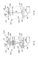
- FIG. 10 is a cross-sectional view of a prior art laser tracker
- FIG. 11 is a block diagram of the computing and communication elements of a laser tracker in accordance with an embodiment of the present invention.
- FIG. 12A is a block diagram of elements in a laser tracker that uses a single wavelength according to an embodiment of the present invention.
- FIG. 12B is a block diagram of elements in a laser tracker that uses a single wavelength according to an embodiment of the present invention.
- FIG. 13 is a block diagram of elements in a laser tracker with six DOF capability according to an embodiment of the present invention.
- FIGS. 14A-D are block diagrams of elements in a laser tracker having six DOF capability according to an embodiment of the present invention.
- FIG. 15 is a block diagram of elements in a laser tracker according to an embodiment of the present invention.
- FIG. 16 is a schematic diagram showing elements within a fiber-optic assembly according to an embodiment of the present invention.
- FIG. 17 is a block diagram of elements in a laser tracker having six DOF capability according to an embodiment of the present invention.
- FIG. 18 is a flowchart of a method for measuring three-dimensional coordinates of a retroreflector target according to embodiments of the present invention.
- FIG. 19 is flowchart of a method for measuring three-dimensional coordinates of a retroreflector target according to embodiments of the present invention.
- An exemplary laser tracker system 5 illustrated in FIG. 1 includes a laser tracker 10 , a retroreflector target 26 , an optional auxiliary unit processor 50 , and an optional auxiliary computer 60 .
- An exemplary gimbaled beam-steering mechanism 12 of laser tracker 10 comprises a zenith carriage 14 mounted on an azimuth base 16 and rotated about an azimuth axis 20 .
- a payload 15 is mounted on the zenith carriage 14 and rotated about a zenith axis 18 .
- Zenith axis 18 and azimuth axis 20 intersect orthogonally, internally to tracker 10 , at gimbal point 22 , which is typically the origin for distance measurements.
- a laser beam 46 virtually passes through the gimbal point 22 and is pointed orthogonal to zenith axis 18 .
- laser beam 46 is approximately perpendicular to any plane parallel to both the zenith axis 18 and the azimuth axis 20 .
- Outgoing laser beam 46 is pointed in the desired direction by rotation of payload 15 about zenith axis 18 and by rotation of zenith carriage 14 about azimuth axis 20 .
- a zenith angular encoder, internal to the tracker, is attached to a zenith mechanical axis aligned to the zenith axis 18 .
- An azimuth angular encoder internal to the tracker, is attached to an azimuth mechanical axis aligned to the azimuth axis 20 .
- the zenith and azimuth angular encoders measure the zenith and azimuth angles of rotation to relatively high accuracy.
- Outgoing laser beam 46 travels to the retroreflector target 26 , which might be, for example, a spherically mounted retroreflector (SMR) as described above.
- SMR spherically mounted retroreflector
- the position of retroreflector 26 is found within the spherical coordinate system of the tracker.
- Outgoing laser beam 46 may include one or more laser wavelengths, as described hereinafter.
- a steering mechanism of the sort shown in FIG. 1 is assumed in the following discussion. However, other types of steering mechanisms are possible. For example, it is possible to reflect a laser beam off a mirror rotated about the azimuth and zenith axes. The techniques described herein are applicable, regardless of the type of steering mechanism.
- Magnetic nests 17 may be included on the laser tracker for resetting the laser tracker to a “home” position for different sized SMRs—for example, 1.5, 7 ⁇ 8, and 1 ⁇ 2 inch SMRs.
- An on-tracker retroreflector 19 may be used to reset the tracker to a reference distance.
- an on-tracker mirror not visible from the view of FIG. 1 , may be used in combination with the on-tracker retroreflector to enable performance of a self-compensation, as described in U.S. Pat. No. 7,327,446, the contents of which are incorporated by reference.
- FIG. 2 shows an exemplary laser tracker system 7 that is like the laser tracker system 5 of FIG. 1 except that retroreflector target 26 is replaced with a six-DOF probe 1000 .
- retroreflector target 26 is replaced with a six-DOF probe 1000 .
- other types of retroreflector targets may be used.
- a cateye retroreflector which is a glass retroreflector in which light focuses to a small spot of light on a reflective rear surface of the glass structure, is sometimes used.
- FIG. 3 is a block diagram showing optical and electrical elements in a laser tracker embodiment. It shows elements of a laser tracker that emit two wavelengths of light—a first wavelength for an ADM and a second wavelength for a visible pointer and for tracking. The visible pointer enables the user to see the position of the laser beam spot emitted by the tracker. The two different wavelengths are combined using a free-space beam splitter.
- Electrooptic (EO) system 100 includes visible light source 110 , isolator 115 , optional first fiber launch 170 , optional interferometer (IFM) 120 , beam expander 140 , first beam splitter 145 , position detector assembly 150 , second beam splitter 155 , ADM 160 , and second fiber launch 170 .
- IDM interferometer
- Visible light source 110 may be a laser, superluminescent diode, or other light emitting device.
- the isolator 115 may be a Faraday isolator, attenuator, or other device capable of reducing the light that reflects back into the light source.
- Optional IFM may be configured in a variety of ways. As a specific example of a possible implementation, the IFM may include a beam splitter 122 , a retroreflector 126 , quarter waveplates 124 , 130 , and a phase analyzer 128 .
- the visible light source 110 may launch the light into free space, the light then traveling in free space through the isolator 115 , and optional IFM 120 .
- the isolator 115 may be coupled to the visible light source 110 by a fiber optic cable.
- the light from the isolator may be launched into free space through the first fiber-optic launch 170 , as discussed herein below with reference to FIG. 5 .
- Beam expander 140 may be set up using a variety of lens configurations, but two commonly used prior-art configurations are shown in FIGS. 4A , 4 B.
- FIG. 4A shows a configuration 140 A based on the use of a negative lens 141 A and a positive lens 142 A.
- a beam of collimated light 220 A incident on the negative lens 141 A emerges from the positive lens 142 A as a larger beam of collimated light 230 A.
- FIG. 4B shows a configuration 140 B based on the use of two positive lenses 141 B, 142 B.
- a beam of collimated light 220 B incident on a first positive lens 141 B emerges from a second positive lens 142 B as a larger beam of collimated light 230 B.
- a small amount reflects off the beam splitters 145 , 155 on the way out of the tracker and is lost. That part of the light that passes through the beam splitter 155 is combined with light from the ADM 160 to form a composite beam of light 188 that leaves that laser tracker and travels to the retroreflector 90 .
- the ADM 160 includes a light source 162 , ADM electronics 164 , a fiber network 166 , an interconnecting electrical cable 165 , and interconnecting optical fibers 168 , 169 , 184 , 186 .
- ADM electronics send electrical modulation and bias voltages to light source 162 , which may, for example, be a distributed feedback laser that operates at a wavelength of approximately 1550 nm.
- the fiber network 166 may be the prior art fiber-optic network 420 A shown in FIG. 8A . In this embodiment, light from the light source 162 in FIG. 3 travels over the optical fiber 184 , which is equivalent to the optical fiber 432 in FIG. 8A .
- the fiber network of FIG. 8A includes a first fiber coupler 430 , a second fiber coupler 436 , and low-transmission reflectors 435 , 440 .
- the light travels through the first fiber coupler 430 and splits between two paths, the first path through optical fiber 433 to the second fiber coupler 436 and the second path through optical fiber 422 and fiber length equalizer 423 .
- Fiber length equalizer 423 connects to fiber length 168 in FIG. 3 , which travels to the reference channel of the ADM electronics 164 .
- the purpose of fiber length equalizer 423 is to match the length of optical fibers traversed by light in the reference channel to the length of optical fibers traversed by light in the measure channel.
- Matching the fiber lengths in this way reduces ADM errors caused by changes in the ambient temperature. Such errors may arise because the effective optical path length of an optical fiber is equal to the average index of refraction of the optical fiber times the length of the fiber. Since the index of refraction of the optical fibers depends on the temperature of the fiber, a change in the temperature of the optical fibers causes changes in the effective optical path lengths of the measure and reference channels. If the effective optical path length of the optical fiber in the measure channel changes relative to the effective optical path length of the optical fiber in the reference channel, the result will be an apparent shift in the position of the retroreflector target 90 , even if the retroreflector target 90 is kept stationary. To get around this problem, two steps are taken.
- the length of the fiber in the reference channel is matched, as nearly as possible, to the length of the fiber in the measure channel.
- the measure and reference fibers are routed side by side to the extent possible to ensure that the optical fibers in the two channels see nearly the same changes in temperature.
- the light travels through the second fiber optic coupler 436 and splits into two paths, the first path to the low-reflection fiber terminator 440 and the second path to optical fiber 438 , from which it travels to optical fiber 186 in FIG. 3 .
- the light on optical fiber 186 travels through to the second fiber launch 170 .
- fiber launch 170 is shown in prior art FIG. 5 .
- the light from optical fiber 186 of FIG. 3 goes to fiber 172 in FIG. 5 .
- the fiber launch 170 includes optical fiber 172 , ferrule 174 , and lens 176 .
- the optical fiber 172 is attached to ferrule 174 , which is stably attached to a structure within the laser tracker 10 . If desired, the end of the optical fiber may be polished at an angle to reduce back reflections.
- the light 250 emerges from the core of the fiber, which may be a single mode optical fiber with a diameter of between 4 and 12 micrometers, depending on the wavelength of the light being used and the particular type of optical fiber.
- the light 250 diverges at an angle and intercepts lens 176 , which collimates it.
- the method of launching and receiving an optical signal through a single optical fiber in an ADM system was described in reference to FIG. 3 in patent '758.
- the beam splitter 155 may be a dichroic beam splitter, which transmits different wavelengths than it reflects.
- the light from the ADM 160 reflects off dichroic beam splitter 155 and combines with the light from the visible laser 110 , which is transmitted through the dichroic beam splitter 155 .
- the composite beam of light 188 travels out of the laser tracker to retroreflector 90 as a first beam, which returns a portion of the light as a second beam. That portion of the second beam that is at the ADM wavelength reflects off the dichroic beam splitter 155 and returns to the second fiber launch 170 , which couples the light back into the optical fiber 186 .
- the optical fiber 186 corresponds to the optical fiber 438 in FIG. 8A .
- the returning light travels from optical fiber 438 through the second fiber coupler 436 and splits between two paths.
- a first path leads to optical fiber 424 that, in an embodiment, corresponds to optical fiber 169 that leads to the measure channel of the ADM electronics 164 in FIG. 3 .
- a second path leads to optical fiber 433 and then to the first fiber coupler 430 .
- the light leaving the first fiber coupler 430 splits between two paths, a first path to the optical fiber 432 and a second path to the low reflectance termination 435 .
- optical fiber 432 corresponds to the optical fiber 184 , which leads to the light source 162 in FIG. 3 .
- the light source 162 contains a built-in Faraday isolator that minimizes the amount of light that enters the light source from optical fiber 432 . Excessive light fed into a laser in the reverse direction can destabilize the laser.
- optical fiber 168 in FIG. 3 corresponds to optical fiber 3232 in FIG. 7
- optical fiber 169 in FIG. 3 corresponds to optical fiber 3230 in FIG. 7 .
- ADM electronics 3300 includes a frequency reference 3302 , a synthesizer 3304 , a measure detector 3306 , a reference detector 3308 , a measure mixer 3310 , a reference mixer 3312 , conditioning electronics 3314 , 3316 , 3318 , 3320 , a divide-by-N prescaler 3324 , and an analog-to-digital converter (ADC) 3322 .
- the frequency reference which might be an oven-controlled crystal oscillator (OCXO), for example, sends a reference frequency f REF , which might be 10 MHz, for example, to the synthesizer, which generates two electrical signals—one signal at a frequency f RF and two signals at frequency f LO .
- the signal f RF goes to the light source 3102 , which corresponds to the light source 162 in FIG. 3 .
- the two signals at frequency f LO go to the measure mixer 3310 and the reference mixer 3312 .
- the light from optical fibers 168 , 169 in FIG. 3 appear on fibers 3232 , 3230 in FIG. 7 , respectively, and enter the reference and measure channels, respectively.
- Reference detector 3308 and measure detector 3306 convert the optical signals into electrical signals. These signals are conditioned by electrical components 3316 , 3314 , respectively, and are sent to mixers 3312 , 3310 , respectively.
- the mixers produce a frequency f IF equal to the absolute value of f LO f RF .
- the signal f RF may be a relatively high frequency, for example, 2 GHz, while the signal f IF may have a relatively low frequency, for example, 10 kHz.
- the reference frequency f REF is sent to the prescaler 3324 , which divides the frequency by an integer value. For example, a frequency of 10 MHz might be divided by a 40 to obtain an output frequency of 250 kHz. In this example, the 10 kHz signals entering the ADC 3322 would be sampled at a rate of 250 kHz, thereby producing 25 samples per cycle.
- the signals from the ADC 3322 are sent to a data processor 3400 , which might, for example, be one or more digital signal processor (DSP) units located in ADM electronics 164 of FIG. 3 .
- DSP digital signal processor
- the method for extracting a distance is based on the calculation of phase of the ADC signals for the reference and measure channels. This method is described in detail in U.S. Pat. No. 7,701,559 (559) to Bridges et al., the contents of which are herein incorporated by reference. Calculation includes use of equations (1)-(8) of patent '559.
- the frequencies generated by the synthesizer are changed some number of times (for example, three times), and the possible ADM distances calculated in each case. By comparing the possible ADM distances for each of the selected frequencies, an ambiguity in the ADM measurement is removed.
- patent '559 and the Kalman filter methods described in patent '559 enable the ADM to measure a moving target.
- other methods of obtaining absolute distance measurements for example, by using pulsed time-of-flight rather than phase differences, may be used.
- the part of the return light beam 190 that passes through the beam splitter 155 arrives at the beam splitter 145 , which sends part of the light to the beam expander 140 and another part of the light to the position detector assembly 150 .
- the light emerging from the laser tracker 10 or EO system 100 may be thought of as a first beam and the portion of that light reflecting off the retroreflector 90 or 26 as a second beam. Portions of the reflected beam are sent to different functional elements of the EO system 100 . For example, a first portion may be sent to a distance meter such as an ADM 160 in FIG. 3 . A second portion may be sent to a position detector assembly 150 . In some cases, a third portion may be sent to other functional units such as an optional interferometer ( 120 ).
- the first portion and the second portion of the second beam are sent to the distance meter and the position detector after reflecting off beam splitters 155 and 145 , respectively, it would have been possible to transmit, rather than reflect, the light onto a distance meter or position detector.
- FIGS. 6A-D Four examples of prior art position detector assemblies 150 A- 150 D are shown in FIGS. 6A-D .
- FIG. 6A depicts the simplest implementation, with the position detector assembly including a position sensor 151 mounted on a circuit board 152 that obtains power from and returns signals to electronics box 350 , which may represent electronic processing capability at any location within the laser tracker 10 , auxiliary unit 50 , or external computer 60 .
- FIG. 6B includes an optical filter 154 that blocks unwanted optical wavelengths from reaching the position sensor 151 . The unwanted optical wavelengths may also be blocked, for example, by coating the beam splitter 145 or the surface of the position sensor 151 with an appropriate film.
- FIG. 6C includes a lens 153 that reduces the size of the beam of light.
- FIG. 6D includes both an optical filter 154 and a lens 153 .
- FIG. 6E shows a position detector assembly according to embodiments of the present invention that includes an optical conditioner 149 E.
- Optical conditioner contains a lens 153 and may also contain optional wavelength filter 154 .
- it includes at least one of a diffuser 156 and a spatial filter 157 .
- a popular type of retroreflector is the cube-corner retroreflector.
- One type of cube corner retroreflector is made of three mirrors, each joined at right angles to the other two mirrors. Lines of intersection at which these three mirrors are joined may have a finite thickness in which light is not perfectly reflected back to the tracker.
- the lines of finite thickness are diffracted as they propagate so that upon reaching the position detector they may not appear exactly the same as at the position detector.
- the diffracted light pattern will generally depart from perfect symmetry.
- the light that strikes the position detector 151 may have, for example, dips or rises in optical power (hot spots) in the vicinity of the diffracted lines.
- a diffuser 156 may be advantageous to include to improve the smoothness of the light that strikes the position detector 151 .
- the diffuser 156 is a holographic diffuser.
- a holographic diffuser provides controlled, homogeneous light over a specified diffusing angle.
- other types of diffusers such as ground glass or “opal” diffusers are used.
- the purpose of the spatial filter 157 of the position detector assembly 150 E is to block ghost beams that may be the result, for example, of unwanted reflections off optical surfaces, from striking the position detector 151 .
- a spatial filter includes a plate 157 that has an aperture. By placing the spatial filter 157 a distance away from the lens equal approximately to the focal length of the lens, the returning light 243 E passes through the spatial filter when it is near its narrowest—at the waist of the beam. Beams that are traveling at a different angle, for example, as a result of reflection of an optical element strike the spatial filter away from the aperture and are blocked from reaching the position detector 151 . An example is shown in FIG.
- an unwanted ghost beam 244 E reflects off a surface of the beam splitter 145 and travels to spatial filter 157 , where it is blocked. Without the spatial filter, the ghost beam 244 E would have intercepted the position detector 151 , thereby causing the position of the beam 243 E on the position detector 151 to be incorrectly determined. Even a weak ghost beam may significantly change the position of the centroid on the position detector 151 if the ghost beam is located a relatively large distance from the main spot of light.
- a retroreflector of the sort discussed here a cube corner or a cateye retroreflector, for example, has the property of reflecting a ray of light that enters the retroreflector in a direction parallel to the incident ray.
- the incident and reflected rays are symmetrically placed about the point of symmetry of the retroreflector.
- the point of symmetry of the retroreflector is the vertex of the cube corner.
- the point of symmetry is also the vertex, but one must consider the bending of the light at the glass-air interface in this case.
- the point of symmetry is the center of the sphere.
- the point of symmetry is a point lying on the plane and at the spherical center of each hemisphere. The main point is that, for the type of retroreflectors ordinarily used with laser trackers, the light returned by a retroreflector to the tracker is shifted to the other side of the vertex relative to the incident laser beam.
- This behavior of a retroreflector 90 in FIG. 3 is the basis for the tracking of the retroreflector by the laser tracker.
- the position sensor has on its surface an ideal retrace point.
- the ideal retrace point is the point at which a laser beam sent to the point of symmetry of a retroreflector (e.g., the vertex of the cube corner retroreflector in an SMR) will return.
- the retrace point is near the center of the position sensor. If the laser beam is sent to one side of the retroreflector, it reflects back on the other side and appears off the retrace point on the position sensor.
- the control system of the laser tracker 10 can cause the motors to move the light beam toward the point of symmetry of the retroreflector.
- the retroreflector If the retroreflector is moved transverse to the tracker at a constant velocity, the light beam at the retroreflector will strike the retroreflector (after transients have settled) a fixed offset distance from the point of symmetry of the retroreflector.
- the laser tracker makes a correction to account for this offset distance at the retroreflector based on scale factor obtained from controlled measurements and based on the distance from the light beam on the position sensor to the ideal retrace point.
- the position detector performs two important functions—enabling tracking and correcting measurements to account for the movement of the retroreflector.
- the position sensor within the position detector may be any type of device capable of measuring a position.
- the position sensor might be a position sensitive detector or a photosensitive array.
- the position sensitive detector might be lateral effect detector or a quadrant detector, for example.
- the photosensitive array might be a CMOS or CCD array, for example.
- the return light that does not reflect off beam splitter 145 passes through beam expander 140 , thereby becoming smaller.
- the positions of the position detector and the distance meter are reversed so that the light reflected by the beam splitter 145 travels to the distance meter and the light transmitted by the beam splitter travels to the position detector.
- the light continues through optional IFM, through the isolator and into the visible light source 110 .
- the optical power should be small enough so that it does not destabilize the visible light source 110 .
- the light from visible light source 110 is launched through a beam launch 170 of FIG. 5 .
- the fiber launch may be attached to the output of light source 110 or a fiber optic output of the isolator 115 .
- the fiber network 166 of FIG. 3 is prior art fiber network 420 B of FIG. 8B .
- the optical fibers 184 , 186 , 168 , 169 of FIG. 3 correspond to optical fibers 443 , 444 , 424 , 422 of FIG. 8B .
- the fiber network of FIG. 8B is like the fiber network of FIG. 8A except that the fiber network of FIG. 8B has a single fiber coupler instead of two fiber couplers.
- the advantage of FIG. 8B over FIG. 8A is simplicity; however, FIG. 8B is more likely to have unwanted optical back reflections entering the optical fibers 422 and 424 .
- the fiber network 166 of FIG. 3 is fiber network 420 C of FIG. 8C .
- the optical fibers 184 , 186 , 168 , 169 of FIG. 3 correspond to optical fibers 447 , 455 , 423 , 424 of FIG. 8C .
- the fiber network 420 C includes a first fiber coupler 445 and a second fiber coupler 451 .
- the first fiber coupler 445 is a 2 ⁇ 2 coupler having two input ports and two output ports. Couplers of this type are usually made by placing two fiber cores in close proximity and then drawing the fibers while heated. In this way, evanescent coupling between the fibers can split off a desired fraction of the light to the adjacent fiber.
- the second fiber coupler 451 is of the type called a circulator. It has three ports, each having the capability of transmitting or receiving light, but only in the designated direction. For example, the light on optical fiber 448 enters port 453 and is transported toward port 454 as indicated by the arrow. At port 454 , light may be transmitted to optical fiber 455 . Similarly, light traveling on port 455 may enter port 454 and travel in the direction of the arrow to port 456 , where some light may be transmitted to the optical fiber 424 . If only three ports are needed, then the circulator 451 may suffer less losses of optical power than the 2 ⁇ 2 coupler. On the other hand, a circulator 451 may be more expensive than a 2 ⁇ 2 coupler, and it may experience polarization mode dispersion, which can be problematic in some situations.
- FIGS. 9 and 10 show exploded and cross sectional views, respectively, of a prior art laser tracker 2100 , which is depicted in FIGS. 2 and 3 of U.S. Published Patent Application No. 2010/0128259 to Bridges et al., incorporated by reference.
- Azimuth assembly 2110 includes post housing 2112 , azimuth encoder assembly 2120 , lower and upper azimuth bearings 2114 A, 2114 B, azimuth motor assembly 2125 , azimuth slip ring assembly 2130 , and azimuth circuit boards 2135 .
- azimuth encoder assembly 2120 The purpose of azimuth encoder assembly 2120 is to accurately measure the angle of rotation of yoke 2142 with respect to the post housing 2112 .
- Azimuth encoder assembly 2120 includes encoder disk 2121 and read-head assembly 2122 .
- Encoder disk 2121 is attached to the shaft of yoke housing 2142
- read head assembly 2122 is attached to post assembly 2110 .
- Read head assembly 2122 comprises a circuit board onto which one or more read heads are fastened.
- Laser light sent from read heads reflect off fine grating lines on encoder disk 2121 . Reflected light picked up by detectors on encoder read head(s) is processed to find the angle of the rotating encoder disk in relation to the fixed read heads.
- Azimuth motor assembly 2125 includes azimuth motor rotor 2126 and azimuth motor stator 2127 .
- Azimuth motor rotor comprises permanent magnets attached directly to the shaft of yoke housing 2142 .
- Azimuth motor stator 2127 comprises field windings that generate a prescribed magnetic field. This magnetic field interacts with the magnets of azimuth motor rotor 2126 to produce the desired rotary motion.
- Azimuth motor stator 2127 is attached to post frame 2112 .
- Azimuth circuit boards 2135 represent one or more circuit boards that provide electrical functions required by azimuth components such as the encoder and motor.
- Azimuth slip ring assembly 2130 includes outer part 2131 and inner part 2132 .
- wire bundle 2138 emerges from auxiliary unit processor 50 .
- Wire bundle 2138 may carry power to the tracker or signals to and from the tracker. Some of the wires of wire bundle 2138 may be directed to connectors on circuit boards. In the example shown in FIG. 10 , wires are routed to azimuth circuit board 2135 , encoder read head assembly 2122 , and azimuth motor assembly 2125 . Other wires are routed to inner part 2132 of slip ring assembly 2130 .
- Inner part 2132 is attached to post assembly 2110 and consequently remains stationary.
- Outer part 2131 is attached to yoke assembly 2140 and consequently rotates with respect to inner part 2132 .
- Slip ring assembly 2130 is designed to permit low impedance electrical contact as outer part 2131 rotates with respect to the inner part 2132 .
- Zenith assembly 2140 comprises yoke housing 2142 , zenith encoder assembly 2150 , left and right zenith bearings 2144 A, 2144 B, zenith motor assembly 2155 , zenith slip ring assembly 2160 , and zenith circuit board 2165 .
- Zenith encoder assembly 2150 The purpose of zenith encoder assembly 2150 is to accurately measure the angle of rotation of payload frame 2172 with respect to yoke housing 2142 .
- Zenith encoder assembly 2150 comprises zenith encoder disk 2151 and zenith read-head assembly 2152 .
- Encoder disk 2151 is attached to payload housing 2142
- read head assembly 2152 is attached to yoke housing 2142 .
- Zenith read head assembly 2152 comprises a circuit board onto which one or more read heads are fastened.
- Laser light sent from read heads reflect off fine grating lines on encoder disk 2151 . Reflected light picked up by detectors on encoder read head(s) is processed to find the angle of the rotating encoder disk in relation to the fixed read heads.
- Zenith motor assembly 2155 comprises azimuth motor rotor 2156 and azimuth motor stator 2157 .
- Zenith motor rotor 2156 comprises permanent magnets attached directly to the shaft of payload frame 2172 .
- Zenith motor stator 2157 comprises field windings that generate a prescribed magnetic field. This magnetic field interacts with the rotor magnets to produce the desired rotary motion.
- Zenith motor stator 2157 is attached to yoke frame 2142 .
- Zenith circuit board 2165 represents one or more circuit boards that provide electrical functions required by zenith components such as the encoder and motor.
- Zenith slip ring assembly 2160 comprises outer part 2161 and inner part 2162 .
- Wire bundle 2168 emerges from azimuth outer slip ring 2131 and may carry power or signals. Some of the wires of wire bundle 2168 may be directed to connectors on circuit board. In the example shown in FIG. 10 , wires are routed to zenith circuit board 2165 , zenith motor assembly 2150 , and encoder read head assembly 2152 . Other wires are routed to inner part 2162 of slip ring assembly 2160 .
- Inner part 2162 is attached to yoke frame 2142 and consequently rotates in azimuth angle only, but not in zenith angle.
- Outer part 2161 is attached to payload frame 2172 and consequently rotates in both zenith and azimuth angles.
- Slip ring assembly 2160 is designed to permit low impedance electrical contact as outer part 2161 rotates with respect to the inner part 2162 .
- Payload assembly 2170 includes a main optics assembly 2180 and a secondary optics assembly 2190 .
- FIG. 11 is a block diagram depicting a dimensional measurement electronics processing system 1500 that includes a laser tracker electronics processing system 1510 , peripheral elements 1582 , 1584 , 1586 , computer 1590 , and other networked components 1600 , represented here as a cloud.
- Exemplary laser tracker electronics processing system 1510 includes a master processor 1520 , payload functions electronics 1530 , azimuth encoder electronics 1540 , zenith encoder electronics 1550 , display and user interface (UI) electronics 1560 , removable storage hardware 1565 , radio frequency identification (RFID) electronics, and an antenna 1572 .
- UI user interface
- the payload functions electronics 1530 includes a number of subfunctions including the six-DOF electronics 1531 , the camera electronics 1532 , the ADM electronics 1533 , the position detector (PSD) electronics 1534 , and the level electronics 1535 . Most of the subfunctions have at least one processor unit, which might be a digital signal processor (DSP) or field programmable gate array (FPGA), for example.
- the electronics units 1530 , 1540 , and 1550 are separated as shown because of their location within the laser tracker.
- the payload functions 1530 are located in the payload 2170 of FIGS. 9 , 10 , while the azimuth encoder electronics 1540 is located in the azimuth assembly 2110 and the zenith encoder electronics 1550 is located in the zenith assembly 2140 .
- peripheral devices Many types of peripheral devices are possible, but here three such devices are shown: a temperature sensor 1582 , a six-DOF probe 1584 , and a personal digital assistant, 1586 , which might be a smart phone, for example.
- the laser tracker may communicate with peripheral devices in a variety of means, including wireless communication over the antenna 1572 , by means of a vision system such as a camera, and by means of distance and angular readings of the laser tracker to a cooperative target such as the six-DOF probe 1584 .
- a separate communications bus goes from the master processor 1520 to each of the electronics units 1530 , 1540 , 1550 , 1560 , 1565 , and 1570 .
- Each communications line may have, for example, three serial lines that include the data line, clock line, and frame line.
- the frame line indicates whether or not the electronics unit should pay attention to the clock line. If it indicates that attention should be given, the electronics unit reads the current value of the data line at each clock signal.
- the clock signal may correspond, for example, to a rising edge of a clock pulse.
- information is transmitted over the data line in the form of a packet.
- each packet includes an address, a numeric value, a data message, and a checksum.
- the address indicates where, within the electronics unit, the data message is to be directed.
- the location may, for example, correspond to a processor subroutine within the electronics unit.
- the numeric value indicates the length of the data message.
- the data message contains data or instructions for the electronics unit to carry out.
- the checksum is a numeric value that is used to minimize the chance that errors are transmitted over the communications line.
- the master processor 1520 sends packets of information over bus 1610 to payload functions electronics 1530 , over bus 1611 to azimuth encoder electronics 1540 , over bus 1612 to zenith encoder electronics 1550 , over bus 1613 to display and UI electronics 1560 , over bus 1614 to removable storage hardware 1565 , and over bus 1616 to RFID and wireless electronics 1570 .
- master processor 1520 also sends a synch (synchronization) pulse over the synch bus 1630 to each of the electronics units at the same time.
- the synch pulse provides a way of synchronizing values collected by the measurement functions of the laser tracker.
- the azimuth encoder electronics 1540 and the zenith electronics 1550 latch their encoder values as soon as the synch pulse is received.
- the payload functions electronics 1530 latch the data collected by the electronics contained within the payload.
- the six-DOF, ADM, and position detector all latch data when the synch pulse is given. In most cases, the camera and inclinometer collect data at a slower rate than the synch pulse rate but may latch data at multiples of the synch pulse period.
- the azimuth encoder electronics 1540 and zenith encoder electronics 1550 are separated from one another and from the payload electronics 1530 by the slip rings 2130 , 2160 shown in FIGS. 9 , 10 . This is why the bus lines 1610 , 1611 , and 1612 are depicted as separate bus line in FIG. 11 .
- the laser tracker electronics processing system 1510 may communicate with an external computer 1590 , or it may provide computation, display, and UI functions within the laser tracker.
- the laser tracker communicates with computer 1590 over communications link 1606 , which might be, for example, and Ethernet line or a wireless connection.
- the laser tracker may also communicate with other elements 1600 , represented by the cloud, over communications link 1602 , which might include one or more electrical cables, such as Ethernet cables, and one or more wireless connections.
- An example of an element 1600 is another three dimensional test instrument—for example, an articulated arm CMM, which may be relocated by the laser tracker.
- a communication link 1604 between the computer 1590 and the elements 1600 may be wired (e.g., Ethernet) or wireless.
- An operator sitting on a remote computer 1590 may make a connection to the Internet, represented by the cloud 1600 , over an Ethernet or wireless line, which in turn connects to the master processor 1520 over an Ethernet or wireless line. In this way, a user may control the action of a remote laser tracker.
- the red wavelength may be provided by a frequency stabilized helium-neon (HeNe) laser suitable for use in an interferometer and also for use in providing a red pointer beam.
- HeNe frequency stabilized helium-neon
- the red wavelength may be provided by a diode laser that serves just as a pointer beam.
- a disadvantage in using two light sources is the extra space and added cost required for the extra light sources, beam splitters, isolators, and other components.
- Another disadvantage in using two light sources is that it is difficult to perfectly align the two light beams along the entire paths the beams travel. This may result in a variety of problems including inability to simultaneously obtain good performance from different subsystems that operate at different wavelengths.
- a system that uses a single light source, thereby eliminating these disadvantages, is shown in optoelectronic system 500 of FIG. 12A .
- FIG. 12A includes a visible light source 110 , an isolator 115 , a fiber network 420 , ADM electronics 530 , a fiber launch 170 , a beam splitter 145 , and a position detector 150 .
- the visible light source 110 might be, for example, a red or green diode laser or a vertical cavity surface emitting laser (VCSEL).
- the isolator might be a Faraday isolator, an attenuator, or any other device capable of sufficiently reducing the amount of light fed back into the light source.
- the light from the isolator 115 travels into the fiber network 420 , which in an embodiment is the fiber network 420 A of FIG. 8A .
- FIG. 12B shows an embodiment of an optoelectronic system 400 in which a single wavelength of light is used but wherein modulation is achieved by means of electro-optic modulation of the light rather than by direct modulation of a light source.
- the optoelectronic system 400 includes a visible light source 110 , an isolator 115 , an electrooptic modulator 410 , ADM electronics 475 , a fiber network 420 , a fiber launch 170 , a beam splitter 145 , and a position detector 150 .
- the visible light source 110 may be, for example, a red or green laser diode.
- Laser light is sent through an isolator 115 , which may be a Faraday isolator or an attenuator, for example.
- the isolator 115 may be fiber coupled at its input and output ports.
- the isolator 115 sends the light to the electrooptic modulator 410 , which modulates the light to a selected frequency, which may be up to 10 GHz or higher if desired.
- An electrical signal 476 from ADM electronics 475 drives the modulation in the electrooptic modulator 410 .
- the modulated light from the electrooptic modulator 410 travels to the fiber network 420 , which might be the fiber network 420 A, 420 B, 420 C, or 420 D discussed hereinabove. Some of the light travels over optical fiber 422 to the reference channel of the ADM electronics 475 .
- Another portion of the light travels out of the tracker, reflects off retroreflector 90 , returns to the tracker, and arrives at the beam splitter 145 .
- a small amount of the light reflects off the beam splitter and travels to position detector 150 , which has been discussed hereinabove with reference to FIGS. 6A-F .
- a portion of the light passes through the beam splitter 145 into the fiber launch 170 , through the fiber network 420 into the optical fiber 424 , and into the measure channel of the ADM electronics 475 .
- the system 500 of FIG. 12A can be manufactured for less money than system 400 of FIG. 12B ; however, the electro-optic modulator 410 may be able to achieve a higher modulation frequency, which can be advantageous in some situations.
- FIG. 13 shows an embodiment of a locator camera system 950 and an optoelectronic system 900 in which an orientation camera is combined with the optoelectronic functionality of a 3D laser tracker to measure six degrees of freedom.
- the optoelectronic system 900 includes a visible light source 905 , an isolator 910 , an optional electrooptic modulator 410 , ADM electronics 715 , a fiber network 420 , a fiber launch 170 , a beam splitter 145 , a position detector 150 , a beam splitter 922 , and an orientation camera 910 .
- the light from the visible light source is emitted in optical fiber 980 and travels through isolator 910 , which may have optical fibers coupled on the input and output ports.
- the light may travel through the electrooptic modulator 410 modulated by an electrical signal 716 from the ADM electronics 715 .
- the ADM electronics 715 may send an electrical signal over cable 717 to modulate the visible light source 905 .
- Some of the light entering the fiber network travels through the fiber length equalizer 423 and the optical fiber 422 to enter the reference channel of the ADM electronics 715 .
- An electrical signal 469 may optionally be applied to the fiber network 420 to provide a switching signal to a fiber optic switch within the fiber network 420 .
- the six DOF device 4000 may be a probe, a scanner, a projector, a sensor, or other device.
- the light from the six-DOF device 4000 enters the optoelectronic system 900 and arrives at beamsplitter 922 .
- Part of the light is reflected off the beamsplitter 922 and enters the orientation camera 910 .
- the orientation camera 910 records the positions of some marks placed on the retroreflector target. From these marks, the orientation angle (i.e., three degrees of freedom) of the six-DOF probe is found.
- the principles of the orientation camera are described hereinafter in the present application and also in patent '758.
- a portion of the light at beam splitter 145 travels through the beamsplitter and is put onto an optical fiber by the fiber launch 170 .
- the light travels to fiber network 420 .
- Part of this light travels to optical fiber 424 , from which it enters the measure channel of the ADM electronics 715 .
- the locator camera system 950 includes a camera 960 and one or more light sources 970 .
- the camera includes a lens system 962 , a photosensitive array 964 , and a body 966 .
- One use of the locator camera system 950 is to locate retroreflector targets in the work volume. It does this by flashing the light source 970 , which the camera picks up as a bright spot on the photosensitive array 964 .
- a second use of the locator camera system 950 is establish a coarse orientation of the six-DOF device 4000 based on the observed location of a reflector spot or LED on the six-DOF device 4000 .
- the direction to each retroreflector target in the work volume may be calculated using the principles of triangulation. If a single locator camera is located to pick up light reflected along the optical axis of the laser tracker, the direction to each retroreflector target may be found. If a single camera is located off the optical axis of the laser tracker, then approximate directions to the retroreflector targets may be immediately obtained from the image on the photosensitive array. In this case, a more accurate direction to a target may be found by rotating the mechanical axes of the laser to more than one direction and observing the change in the spot position on the photosensitive array.
- the electrooptics module 176 includes a combination of optical components, such as beam splitters and waveplates, and optoelectronic components, such as optical detectors and amplifiers, to separate the phase difference d into quadrature components.
- These quadrature components include sin(d) 188 and cos(d) 190.
- An electrical counter uses the quadrature components to count the number of complete 360 degree shifts in the phase difference d. This number of counts (and possibly a fraction of a count) is sent the counter 178 , which keeps track of the number of counts. This number of counts is sent over a line 180 to a processor, which calculates a distance corresponding to the number of counts.
- FIG. 14A shows an embodiment of an orientation camera 910 , which may be used in the optoelectronic systems of FIGS. 18 and 19 .
- the general principles of the orientation camera are described in patent '758 and are generally adhered to in orientation camera 910 .
- the orientation camera 910 includes a body 1210 , an afocal beam reducer 1220 , a magnifier 1240 , a path length adjuster 1230 , an actuator assembly 1260 , and a photosensitive array 1250 .
- the afocal beam reducer includes a positive lens 1222 , a mirror 1223 , and negative lenses 1224 , 1226 .
- the afocal beam reducer has the property that a ray of light that enters lens 1222 parallel to an optical axis—an axis that passes through the center of the lenses—emerges from lens 1226 also parallel to the optical axis.
- the afocal beam reducer also has the property that an image has a constant size regardless of the distance from the lens to an object.
- the magnifier 1240 includes a positive lens 1242 , negative lenses 1244 , 1248 , and a mirror 1246 . The magnifier has the same function as a microscope objective but is scaled to provide a larger image.
- the photosensitive array 1250 may, for example, be a CMOS or CCD array that converts the light that strikes it into an array of digital values representing the irradiance of the light at each pixel of the photosensitive array.
- the pattern of irradiance may reveal, for example, the marks on a six-DOF target.
- the path length adjuster 1230 includes a platform 1231 , two mirrors 1232 , 1233 , and a ball slide 1234 .
- the mirrors 1232 , 1233 are mounted on the platform 1231 so that when the platform 1231 is moved, the distance between the afocal beam reducer 1220 and the magnifier 1240 is changed.
- the platform 1231 is mounted on the ball slide 1234 , which provides the platform with low friction linear motion.
- the actuator assembly 1260 includes a motor 1261 , a motor shaft 1262 , a flexible coupling 1263 , an adapter 1264 , and a motor nut 1265 .
- the motor nut 1265 is fixedly attached to the adapter. As the threaded motor shaft 1262 is rotated by the motor 1261 , the motor nut 1265 is moved either farther from or nearer to the motor, depending on the direction of rotation of the motor shaft.
- the flexible coupler 1263 which is attached to the adapter 1264 , allows the platform to move freely even if the motor shaft 1262 and the ball slide 1234 are not parallel to one another.
- the orientation camera 910 provides constant transverse magnification for different distances to the target.
- transverse magnification is defined as the image size divided by the object size.
- the lenses shown in FIG. 14A were selected to produce a constant image size on the photosensitive array 1250 of 3 mm for an object size of 13 mm.
- This transverse magnification is held constant for a target placed a distance from the tracker of between 0.5 meter and 30 meters.
- This image size of 3 mm might be appropriate for a 1 ⁇ 4 inch CCD or CMOS array.
- the transverse magnification is four times this amount, making it appropriate for a one inch CCD or CMOS array.
- An orientation camera with this increased transverse magnification can be obtained in the same size body 1210 , by changing the focal lengths and spacings of the three lenses in the magnifier 1240 .
- the effective focal lengths of the three lens elements 1222 , 1224 , and 1226 of the beam reducer 1220 are 85.9 mm, ⁇ 29.6 mm, and ⁇ 7.2 mm, respectively.
- a virtual image is formed after the light from the object passes through these three lens elements.
- the virtual image 1229 has a size of 0.44 mm and is located 7 mm from the lens 1226 .
- the virtual image 1228 has a size of 0.44 mm and is located 1.8 mm from the lens 1224 .
- the distance between the virtual image 1228 and the virtual image 1129 is 39.8 mm, which means that the platform needs a maximum travel range of half this amount, or 19.9 mm.
- the effective focal lengths of the three lens elements 1242 , 1244 , and 1228 of the magnifier are 28.3 mm, ⁇ 8.8 mm, and ⁇ 8.8 mm, respectively.
- the size of the image at the photosensitive array 1250 is 3 mm for a target located 0.5 meter from the laser tracker, 30 meters from the laser tracker, or any distance in between.
- FIGS. 14B-D Another embodiment of an orientation camera is shown in FIGS. 14B-D .
- FIG. 14B is a side view of an orientation camera assembly 2750 B.
- FIG. 14C is a top view 2750 C of a section A-A shown in FIG. 14B .
- FIG. 14D is a side sectional view 2750 D of a section B-B of FIG. 14C .
- the path of light beam 2755 is shown in each of the three figures. Light passes through a first collection of lenses 2760 , reflects off mirror 2762 , passes through lens 2764 , reflects off mirrors 2766 , 2768 , passes through a section collection of lenses 2770 , reflects off mirrors 2772 , 2774 , and strikes photosensitive array 2776 .
- the first collection of lenses 2760 and the lens 2764 form an afocal lens system. As explained herein above, this means that a ray entering the first collection of lenses 2760 parallel to the optical axis will exit the lens 2764 parallel to the optical axis. Because the retroreflector (not shown in FIGS. 14B-D is a finite distance from the laser tracker, the afocal lens system will produce a virtual image 2778 at some distance from the lens 2764 . This distance d from the lens 2764 will depend on the distance from the retroreflector from the laser tracker.
- the second collection of lenses relays the virtual image 2778 onto the photosensitive array.
- a motorized actuator 2780 adjusts the position of mirrors 2766 , 2768 in order to maintain the correct distance from the virtual image 2778 to the second collection of lenses 2770 , thereby keeping the image on the photosensitive array 2776 in focus.
- the first collection of lenses 2755 has a combined focal length of 112 mm
- the lens 2764 has a focal length of ⁇ 5.18 mm
- the second collection of lenses 2770 has a combined focal length of about 59.3 mm.
- the overall magnification of the system is approximately 1 ⁇ 8, which means that the size of the light pattern on the photosensitive array 2776 is about one-eighth the size of the light pattern on the retroreflector. This is an example of a lens system that maintains a constant magnification regardless of the distance from the laser tracker to the retroreflector.
- FIGS. 14A-D are distinguished by having a zoom capability, a narrow field of view, and an alignment with the optical axis of the laser tracker.
- FIG. 15 shows an embodiment of an optoelectronic system 700 in which two different wavelengths of light are combined using a fiber optic coupler.
- the optoelectronic system 700 includes a first light source 705 , a second light source 750 , a first isolator 710 , a second isolator 755 , an optional electrooptic modulator 410 , ADM electronics 715 , a fiber network 720 , a fiber launch 170 , a beam splitter 145 , and a position detector 150 .
- the first light source 705 may be, for example, a diode laser that operates at 780 nm.
- the second light source may be, for example, a red or green diode laser.
- Light from the first light source 705 is sent over an optical fiber 780 through an isolator 710 , which may be a Faraday isolator or an attenuator, for example.
- the isolator 710 may be fiber coupled at its input and output ports.
- the isolator 710 may send the light to an electrooptic modulator 410 , which modulates the light. If the electrooptic modulator 410 is used, an electrical signal 716 from ADM electronics 715 drives the modulation in the electrooptic modulator 410 . Alternatively, if the electrooptic modulator 410 is omitted, the ADM electronics 715 sends a modulation signal directly to the light source 705 .
- the light from the first light source travels through optical fiber 781 to the fiber network 720 . Some of the light is routed through fiber length equalizer 423 and optical fiber 722 into the reference channel of the ADM electronics 715 . Another part of the light travels out of the fiber network 720 through optical fiber 782 to the fiber launch, which sends the light beam 783 into free space. A small amount of the light reflects off beam splitter 145 and is lost. The rest of the light passes through beam splitter 145 , travels to retroreflector 90 as light beam 784 , and travels back to the beam splitter 145 as light beam 786 . Some of the light reflects off the beam splitter 145 and travels to the position detector 150 . Another part of the light passes through the fiber launch and is coupled back into the optical fiber 782 . The light passes into the fiber network 720 and travels over optical fiber 724 to the measure channel of the ADM electronics 715 .
- the second light source 750 sends a second beam of light onto optical fiber 790 , through isolator 755 , through optical fiber 791 and into fiber network 720 .
- An embodiment of fiber network 720 is shown in FIG. 16 .
- the light from optical fiber 1781 enters fiber network 720 at the input port.
- the light travels through a first fiber coupler 1730 .
- Part of the light travels through optical fiber 1722 and fiber length compensator 1723 before entering the reference channel of ADM electronics 715 .
- Some of the light travels through a second fiber coupler 1740 and a third fiber coupler 1750 before passing out of the fiber network onto optical fiber 1782 .
- the light from optical fiber 1791 enters into the third fiber coupler 1750 , where it is combined with the light from optical fiber 1743 to form a composite light beam that travels on optical fiber 1782 .
- the ports attached to optical fibers 1781 and 1791 are two input ports, and may be considered a first port and a second port.
- the ports attached to optical fibers 1782 and 1755 are output ports and may be considered a third port and a fourth port.
- the optical coupler 1750 is a dichroic coupler because it is designed to use two wavelengths. After the composite light beam carried in optical fiber 1782 travels out of the laser tracker and reflects off retroreflector 90 , it returns to the fiber network 720 .
- the light from the first light source passes through the third fiber coupler 1750 , the second fiber coupler 1740 , and enters optical fiber 1724 , which leads to the measure channel of the ADM electronics 715 .
- the light from the second light source returns to optical fiber 1791 and travels to isolator 755 , which keeps it from entering the second light source 750 .
- the couplers 1730 , 1740 , and 1750 may be of the fused type. With this type of optical coupler, two fiber core/cladding regions are brought close together and fused. Consequently, light between the cores is exchanged by evanescent coupling. In the case of two different wavelengths, it is possible to design an evanescent coupling arrangement that allows complete transmission of a first wavelength along the original fiber and complete coupling of a second wavelength over to the same fiber. In practical cases, it is not usually possible to obtain a complete (100 percent) coupling of the light so that the fiber-optic coupler provides lossless transmission.
- fiber-optic couplers that provide good coupling for two or more different wavelengths may be purchased and are readily available at common wavelengths such as 980 nm, 1300 nm, and 1550 nm.
- fiber-optic couplers may be purchased off-the-shelf for other wavelengths, including visible wavelengths, and may be custom designed and manufactured for other wavelengths.
- FIG. 16 it is possible to design fiber optic coupler 1750 so that the first light at its first wavelength travels from optical fiber 1743 to optical fiber 7153 with low optical loss. At the same time, the design can provide for a nearly complete coupling of the second light on optical fiber 1791 over to the optical fiber 1782 .
- optical couplers that combine wavelengths that differ widely in wavelength.
- the two selected wavelengths might be 633 nm and 780 nm, which are relatively close together in wavelength values and could be transmitted through a single-mode optical fiber over a long distance without a high loss.
- An advantage of the architecture of the electrooptics assembly 700 is that the dichroic fiber coupler 1750 within the fiber network 720 is more compact that a free space beam splitter.
- the dichroic fiber coupler ensures that the first light and the second light are very well aligned without requiring any special optical alignment procedures during production.
- FIG. 17 shows an embodiment of an electrooptic system 1900 similar to the electrooptic system 900 of FIG. 13 except FIG. 17 contains two light sources—a first light source 705 and a second light source 750 .
- the first light source 705 , the second light source 750 , the first isolator 710 , and the second isolator 755 of FIG. 17 are the same components shown in FIG. 15 and described hereinabove.
- FIG. 18 shows a method 4010 for measuring three-dimensional coordinates of a retroreflector target.
- a step 4015 is to provide a coordinate measurement device that includes a first light source that produces a first light at a first wavelength, a second light source that produces a second light at a second wavelength different than the first wavelength, a fiber-optic coupler that includes at least a first port, a second port, and a third port, an optical system, a first motor, a second motor, a first angle measuring device, a second angle measuring device, a distance meter, and a processor.
- a step 4020 is to couple a first portion (at a first wavelength) of the first light into the first port.
- a step 4025 is to couple a second portion (at a second wavelength) of the second light into the second port.
- a fourth step 4030 is to transmit a third light from the third port, the third light containing a portion of the first portion and a portion of the second portion.
- a fifth step 4035 is to transmit a portion of the third light through the optical system and out of the coordinate measurement device as a first beam of light.
- a step 4040 is to direct the first beam of light in a first direction, the first direction determined by a first angle of rotation about a first axis and a second angle of rotation about a second axis, the first angle of rotation produced by the first motor and the second angle of rotation produced by the second motor.
- a step 4045 is to measure the first angle of rotation with the first angle measuring device and to measure a second angle of rotation with the second angle measuring device.
- a step 4050 is to reflect a portion of the first beam from the retroreflector target as a second beam.
- a step 4055 is to measure a first distance from the coordinate measurement device to the retroreflector target with the distance meter, the measured distance based at least in part on a third portion of the second beam of light received by a first optical detector.
- a step 4060 is to determine three-dimensional coordinates of the retroreflector target based at least in part on the first distance, the first angle of rotation, and the second angle of rotation.
- a step 4065 is to store the determined three-dimensional coordinates.
- FIG. 19 shows a method 4110 for measuring three-dimensional coordinates of a retroreflector target.
- a step 4115 is to provide a position detector assembly, the position detector assembly including a position detector.
- a step 4120 is to send a fourth portion of the second beam onto the position detector.
- a step 4125 which follows from the step A of FIG. 18 , is to obtain a first signal from the position detector, the first signal responsive to the position of the fourth portion on the position detector.
- a step 4130 is to send a second signal to the first motor and sending a third signal to the second motor, the second signal and the third signal based at least in part on the first signal.
- a step 4135 is to adjust the first direction of the first beam to the position in space of the retroreflector target. The procedure terminates at step B.
Abstract
Description
Claims (20)
Priority Applications (2)
| Application Number | Priority Date | Filing Date | Title |
|---|---|---|---|
| US13/431,494 US8908154B2 (en) | 2011-04-15 | 2012-03-27 | Laser tracker that combines two different wavelengths with a fiber-optic coupler |
| US14/562,935 US9164173B2 (en) | 2011-04-15 | 2014-12-08 | Laser tracker that uses a fiber-optic coupler and an achromatic launch to align and collimate two wavelengths of light |
Applications Claiming Priority (3)
| Application Number | Priority Date | Filing Date | Title |
|---|---|---|---|
| US201161475703P | 2011-04-15 | 2011-04-15 | |
| US201261592049P | 2012-01-30 | 2012-01-30 | |
| US13/431,494 US8908154B2 (en) | 2011-04-15 | 2012-03-27 | Laser tracker that combines two different wavelengths with a fiber-optic coupler |
Related Child Applications (1)
| Application Number | Title | Priority Date | Filing Date |
|---|---|---|---|
| US14/562,935 Continuation-In-Part US9164173B2 (en) | 2011-04-15 | 2014-12-08 | Laser tracker that uses a fiber-optic coupler and an achromatic launch to align and collimate two wavelengths of light |
Publications (2)
| Publication Number | Publication Date |
|---|---|
| US20120262692A1 US20120262692A1 (en) | 2012-10-18 |
| US8908154B2 true US8908154B2 (en) | 2014-12-09 |
Family
ID=45955180
Family Applications (12)
| Application Number | Title | Priority Date | Filing Date |
|---|---|---|---|
| US13/427,935 Active 2032-04-12 US8537376B2 (en) | 2011-04-15 | 2012-03-23 | Enhanced position detector in laser tracker |
| US13/431,494 Active 2033-01-26 US8908154B2 (en) | 2011-04-15 | 2012-03-27 | Laser tracker that combines two different wavelengths with a fiber-optic coupler |
| US13/434,944 Active US8570493B2 (en) | 2009-08-07 | 2012-03-30 | Absolute distance meter that uses a fiber-optic switch to reduce drift |
| US13/442,165 Active 2032-09-24 US9157987B2 (en) | 2011-04-15 | 2012-04-09 | Absolute distance meter based on an undersampling method |
| US13/443,946 Active 2033-02-26 US9151830B2 (en) | 2011-04-15 | 2012-04-11 | Six degree-of-freedom laser tracker that cooperates with a remote structured-light scanner |
| US13/443,956 Expired - Fee Related US9207309B2 (en) | 2011-04-15 | 2012-04-11 | Six degree-of-freedom laser tracker that cooperates with a remote line scanner |
| US13/444,043 Active US8848203B2 (en) | 2011-04-15 | 2012-04-11 | Six degree-of-freedom laser tracker that cooperates with a remote projector to convey information |
| US13/443,951 Expired - Fee Related US9482746B2 (en) | 2011-04-15 | 2012-04-11 | Six degree-of-freedom laser tracker that cooperates with a remote sensor |
| US13/445,968 Expired - Fee Related US8681320B2 (en) | 2011-04-15 | 2012-04-13 | Gimbal instrument having a prealigned and replaceable optics bench |
| US13/446,211 Active 2032-10-10 US8842259B2 (en) | 2011-04-15 | 2012-04-13 | Laser tracker with enhanced handling features |
| US13/447,328 Active US8558992B2 (en) | 2011-04-15 | 2012-04-16 | Laser tracker with enhanced illumination indicators |
| US15/293,494 Active 2033-04-10 US10302413B2 (en) | 2011-04-15 | 2016-10-14 | Six degree-of-freedom laser tracker that cooperates with a remote sensor |
Family Applications Before (1)
| Application Number | Title | Priority Date | Filing Date |
|---|---|---|---|
| US13/427,935 Active 2032-04-12 US8537376B2 (en) | 2011-04-15 | 2012-03-23 | Enhanced position detector in laser tracker |
Family Applications After (10)
| Application Number | Title | Priority Date | Filing Date |
|---|---|---|---|
| US13/434,944 Active US8570493B2 (en) | 2009-08-07 | 2012-03-30 | Absolute distance meter that uses a fiber-optic switch to reduce drift |
| US13/442,165 Active 2032-09-24 US9157987B2 (en) | 2011-04-15 | 2012-04-09 | Absolute distance meter based on an undersampling method |
| US13/443,946 Active 2033-02-26 US9151830B2 (en) | 2011-04-15 | 2012-04-11 | Six degree-of-freedom laser tracker that cooperates with a remote structured-light scanner |
| US13/443,956 Expired - Fee Related US9207309B2 (en) | 2011-04-15 | 2012-04-11 | Six degree-of-freedom laser tracker that cooperates with a remote line scanner |
| US13/444,043 Active US8848203B2 (en) | 2011-04-15 | 2012-04-11 | Six degree-of-freedom laser tracker that cooperates with a remote projector to convey information |
| US13/443,951 Expired - Fee Related US9482746B2 (en) | 2011-04-15 | 2012-04-11 | Six degree-of-freedom laser tracker that cooperates with a remote sensor |
| US13/445,968 Expired - Fee Related US8681320B2 (en) | 2011-04-15 | 2012-04-13 | Gimbal instrument having a prealigned and replaceable optics bench |
| US13/446,211 Active 2032-10-10 US8842259B2 (en) | 2011-04-15 | 2012-04-13 | Laser tracker with enhanced handling features |
| US13/447,328 Active US8558992B2 (en) | 2011-04-15 | 2012-04-16 | Laser tracker with enhanced illumination indicators |
| US15/293,494 Active 2033-04-10 US10302413B2 (en) | 2011-04-15 | 2016-10-14 | Six degree-of-freedom laser tracker that cooperates with a remote sensor |
Country Status (7)
| Country | Link |
|---|---|
| US (12) | US8537376B2 (en) |
| EP (1) | EP2545396B1 (en) |
| JP (11) | JP2014516409A (en) |
| CN (11) | CN103649673A (en) |
| DE (10) | DE112012001708B4 (en) |
| GB (11) | GB2504890A (en) |
| WO (11) | WO2012141868A1 (en) |
Cited By (5)
| Publication number | Priority date | Publication date | Assignee | Title |
|---|---|---|---|---|
| US20150088448A1 (en) * | 2012-02-10 | 2015-03-26 | Jiangsu Laitz Optoelectronics Technology Co., Ltd. | Calibration method and distance measurement device thereof based on phase measurement of double-wavelength laser tube |
| US9594250B2 (en) | 2013-12-18 | 2017-03-14 | Hexagon Metrology, Inc. | Ultra-portable coordinate measurement machine |
| US9752865B1 (en) | 2016-04-07 | 2017-09-05 | International Business Machines Corporation | Height measurement using optical interference |
| US10302413B2 (en) * | 2011-04-15 | 2019-05-28 | Faro Technologies, Inc. | Six degree-of-freedom laser tracker that cooperates with a remote sensor |
| US10480929B2 (en) | 2010-04-21 | 2019-11-19 | Faro Technologies, Inc. | Method and apparatus for following an operator and locking onto a retroreflector with a laser tracker |
Families Citing this family (226)
| Publication number | Priority date | Publication date | Assignee | Title |
|---|---|---|---|---|
| US8488972B2 (en) * | 2006-05-30 | 2013-07-16 | Tai-Her Yang | Directional control/transmission system with directional light projector |
| US9482755B2 (en) | 2008-11-17 | 2016-11-01 | Faro Technologies, Inc. | Measurement system having air temperature compensation between a target and a laser tracker |
| US8803055B2 (en) * | 2009-01-09 | 2014-08-12 | Automated Precision Inc. | Volumetric error compensation system with laser tracker and active target |
| US8659749B2 (en) | 2009-08-07 | 2014-02-25 | Faro Technologies, Inc. | Absolute distance meter with optical switch |
| US8619265B2 (en) | 2011-03-14 | 2013-12-31 | Faro Technologies, Inc. | Automatic measurement of dimensional data with a laser tracker |
| US9377885B2 (en) | 2010-04-21 | 2016-06-28 | Faro Technologies, Inc. | Method and apparatus for locking onto a retroreflector with a laser tracker |
| US9400170B2 (en) | 2010-04-21 | 2016-07-26 | Faro Technologies, Inc. | Automatic measurement of dimensional data within an acceptance region by a laser tracker |
| RU2010124265A (en) * | 2010-06-16 | 2011-12-27 | Алексей Владиславович Жданов (RU) | METHOD AND DEVICE FOR DETERMINING THE DIRECTION OF THE START OF MOTION |
| US8411285B2 (en) * | 2010-11-22 | 2013-04-02 | Trimble Navigation Limited | Stationing an unleveled optical total station |
| CN102096069B (en) * | 2010-12-17 | 2012-10-03 | 浙江大学 | Real-time processing system and method for phased array three-dimensional acoustic camera sonar |
| US8902408B2 (en) | 2011-02-14 | 2014-12-02 | Faro Technologies Inc. | Laser tracker used with six degree-of-freedom probe having separable spherical retroreflector |
| DE112012001082B4 (en) | 2011-03-03 | 2015-12-03 | Faro Technologies Inc. | Method for measuring goals |
| GB201105587D0 (en) * | 2011-04-01 | 2011-05-18 | Elliptic Laboratories As | User interfaces for electronic devices |
| USD688577S1 (en) | 2012-02-21 | 2013-08-27 | Faro Technologies, Inc. | Laser tracker |
| US9482529B2 (en) | 2011-04-15 | 2016-11-01 | Faro Technologies, Inc. | Three-dimensional coordinate scanner and method of operation |
| US9686532B2 (en) | 2011-04-15 | 2017-06-20 | Faro Technologies, Inc. | System and method of acquiring three-dimensional coordinates using multiple coordinate measurement devices |
| US9164173B2 (en) | 2011-04-15 | 2015-10-20 | Faro Technologies, Inc. | Laser tracker that uses a fiber-optic coupler and an achromatic launch to align and collimate two wavelengths of light |
| US9147199B2 (en) | 2011-06-17 | 2015-09-29 | Google Inc. | Advertisements in view |
| DE112012002943T5 (en) | 2011-07-13 | 2014-04-30 | Faro Technologies Inc. | Apparatus and method using a spatial light modulator for determining 3D coordinates of an object |
| WO2013009677A1 (en) | 2011-07-14 | 2013-01-17 | Faro Technologies, Inc. | Grating-based scanner with phase and pitch adjustment |
| US9444981B2 (en) * | 2011-07-26 | 2016-09-13 | Seikowave, Inc. | Portable structured light measurement module/apparatus with pattern shifting device incorporating a fixed-pattern optic for illuminating a subject-under-test |
| EP2600173A1 (en) * | 2011-11-29 | 2013-06-05 | Hexagon Technology Center GmbH | Method for operating a laser scanner |
| CN104094081A (en) | 2012-01-27 | 2014-10-08 | 法罗技术股份有限公司 | Inspection method with barcode identification |
| EP2847539B1 (en) * | 2012-05-07 | 2020-02-12 | Carl Zeiss Industrielle Messtechnik GmbH | Replaceable illumination module for a co-ordinate measuring machine |
| TWI549655B (en) * | 2012-05-18 | 2016-09-21 | 國立成功大學 | Joint range of motion measuring apparatus and measuring method thereof |
| GB2540075B (en) * | 2012-05-18 | 2017-04-19 | Acergy France SAS | Improvements relating to pipe measurement |
| US9671566B2 (en) | 2012-06-11 | 2017-06-06 | Magic Leap, Inc. | Planar waveguide apparatus with diffraction element(s) and system employing same |
| JP6129309B2 (en) * | 2012-07-12 | 2017-05-17 | デュアル・アパーチャー・インターナショナル・カンパニー・リミテッド | Gesture based user interface |
| US9213101B2 (en) * | 2012-09-13 | 2015-12-15 | Laser Technology, Inc. | Self-aligned aiming system and technique for a laser rangefinder incorporating a retroreflector |
| US9879995B2 (en) | 2012-09-13 | 2018-01-30 | Laser Technology, Inc. | System and method for superimposing a virtual aiming mechanism with a projected system beam in a compact laser-based rangefinding instrument |
| US9354051B2 (en) | 2012-09-13 | 2016-05-31 | Laser Technology, Inc. | System and method for a rangefinding instrument incorporating pulse and continuous wave signal generating and processing techniques for increased distance measurement accuracy |
| US9383753B1 (en) * | 2012-09-26 | 2016-07-05 | Google Inc. | Wide-view LIDAR with areas of special attention |
| DE102012112025B4 (en) | 2012-12-10 | 2016-05-12 | Carl Zeiss Ag | Method and devices for determining the position of a kinematics |
| WO2014094119A1 (en) * | 2012-12-20 | 2014-06-26 | Raytheon Canada Limited | Wide field of view multibeam optical apparatus |
| DE102012223929A1 (en) * | 2012-12-20 | 2014-06-26 | Hilti Aktiengesellschaft | Method and device for determining the two-dimensional location coordinates of a target object |
| CN103134441A (en) * | 2012-12-28 | 2013-06-05 | 中国空气动力研究与发展中心设备设计及测试技术研究所 | Large wind tunnel flexible spraying pipe laser tracking measurement method |
| DE102013104490A1 (en) * | 2013-01-25 | 2014-07-31 | Werth Messtechnik Gmbh | Method and device for determining the geometry of structures by means of computer tomography |
| US9036134B2 (en) * | 2013-02-12 | 2015-05-19 | Faro Technologies, Inc. | Multi-mode optical measurement device and method of operation |
| US9746560B2 (en) * | 2013-02-12 | 2017-08-29 | Faro Technologies, Inc. | Combination scanner and tracker device having a focusing mechanism |
| US9188430B2 (en) | 2013-03-14 | 2015-11-17 | Faro Technologies, Inc. | Compensation of a structured light scanner that is tracked in six degrees-of-freedom |
| US9046360B2 (en) | 2013-03-14 | 2015-06-02 | Faro Technologies, Inc. | System and method of acquiring three dimensional coordinates using multiple coordinate measurement devices |
| US9041914B2 (en) | 2013-03-15 | 2015-05-26 | Faro Technologies, Inc. | Three-dimensional coordinate scanner and method of operation |
| JP6355710B2 (en) * | 2013-03-15 | 2018-07-11 | ファロ テクノロジーズ インコーポレーテッド | Non-contact optical three-dimensional measuring device |
| US9294758B2 (en) * | 2013-04-18 | 2016-03-22 | Microsoft Technology Licensing, Llc | Determining depth data for a captured image |
| US9234742B2 (en) * | 2013-05-01 | 2016-01-12 | Faro Technologies, Inc. | Method and apparatus for using gestures to control a laser tracker |
| EP2801839B1 (en) * | 2013-05-10 | 2020-03-04 | Leica Geosystems AG | Handheld measuring aid for use with a 6-DoF laser tracker |
| TWI487115B (en) * | 2013-06-07 | 2015-06-01 | Sinopower Semiconductor Inc | Trench power device and manufacturing method thereof |
| US9476695B2 (en) | 2013-07-03 | 2016-10-25 | Faro Technologies, Inc. | Laser tracker that cooperates with a remote camera bar and coordinate measurement device |
| US9113154B2 (en) | 2013-07-10 | 2015-08-18 | Faro Technologies, Inc. | Three-dimensional measurement device having three-dimensional overview camera |
| US10228242B2 (en) | 2013-07-12 | 2019-03-12 | Magic Leap, Inc. | Method and system for determining user input based on gesture |
| WO2015006784A2 (en) | 2013-07-12 | 2015-01-15 | Magic Leap, Inc. | Planar waveguide apparatus with diffraction element(s) and system employing same |
| US10812694B2 (en) | 2013-08-21 | 2020-10-20 | Faro Technologies, Inc. | Real-time inspection guidance of triangulation scanner |
| FR3009881B1 (en) | 2013-08-23 | 2017-03-17 | Stmi Soc Des Techniques En Milieu Ionisant | 3D TOPOGRAPHIC AND RADIOLOGICAL MODELING OF AN ENVIRONMENT |
| US9443310B2 (en) * | 2013-10-09 | 2016-09-13 | Microsoft Technology Licensing, Llc | Illumination modules that emit structured light |
| DK2866047T3 (en) * | 2013-10-23 | 2021-03-29 | Ladar Ltd | DETECTION SYSTEM FOR DETECTING AN OBJECT ON A WATER SURFACE |
| EP2881704B1 (en) * | 2013-12-04 | 2018-05-09 | Hexagon Technology Center GmbH | Systems and methods for automated measurement of an object and corresponding computer programme product |
| US9239238B2 (en) * | 2013-12-11 | 2016-01-19 | Faro Technologies, Inc. | Method for correcting a 3D measurement of a spherically mounted retroreflector on a nest |
| US9121689B2 (en) * | 2013-12-11 | 2015-09-01 | Faro Technologies, Inc. | Method for correcting a spherically mounted retroreflector when resetting a distance meter |
| US9606235B2 (en) * | 2014-01-16 | 2017-03-28 | The Boeing Company | Laser metrology system and method |
| US10451482B2 (en) | 2014-02-14 | 2019-10-22 | Palo Alto Research Center Incorporated | Determination of color characteristics of objects using spatially modulated light |
| US9952033B2 (en) | 2014-02-14 | 2018-04-24 | Palo Alto Research Center Incorporated | Spatial modulation of light to determine object length |
| US10061027B2 (en) * | 2014-02-25 | 2018-08-28 | Adsys Controls, Inc. | Laser navigation system and method |
| CN103984193B (en) * | 2014-03-14 | 2020-10-16 | 广州虹天航空科技有限公司 | Photographing apparatus stabilizer and control method thereof |
| USD734337S1 (en) | 2014-04-01 | 2015-07-14 | Datalogic Ip Tech S.R.L. | Coded information reader |
| USD735595S1 (en) | 2014-04-02 | 2015-08-04 | Franklin B White | Support for GPS apparatus |
| US9400174B2 (en) * | 2014-04-07 | 2016-07-26 | Palo Alto Research Center Incorporated | Monitor for particle injector |
| US9903701B2 (en) | 2014-05-14 | 2018-02-27 | Faro Technologies, Inc. | Articulated arm coordinate measurement machine having a rotary switch |
| US9829305B2 (en) | 2014-05-14 | 2017-11-28 | Faro Technologies, Inc. | Metrology device and method of changing operating system |
| US9746308B2 (en) * | 2014-05-14 | 2017-08-29 | Faro Technologies, Inc. | Metrology device and method of performing an inspection |
| US9921046B2 (en) | 2014-05-14 | 2018-03-20 | Faro Technologies, Inc. | Metrology device and method of servicing |
| US9739591B2 (en) | 2014-05-14 | 2017-08-22 | Faro Technologies, Inc. | Metrology device and method of initiating communication |
| US9803969B2 (en) | 2014-05-14 | 2017-10-31 | Faro Technologies, Inc. | Metrology device and method of communicating with portable devices |
| DE102014007908A1 (en) * | 2014-05-27 | 2015-12-03 | Carl Zeiss Meditec Ag | Surgical System |
| US9402070B2 (en) | 2014-06-12 | 2016-07-26 | Faro Technologies, Inc. | Coordinate measuring device with a six degree-of-freedom handheld probe and integrated camera for augmented reality |
| US10021379B2 (en) | 2014-06-12 | 2018-07-10 | Faro Technologies, Inc. | Six degree-of-freedom triangulation scanner and camera for augmented reality |
| DE102014009269B4 (en) * | 2014-06-25 | 2017-06-08 | Thyssenkrupp Ag | Device for the spatial alignment of a non-contact measuring head |
| US9395174B2 (en) | 2014-06-27 | 2016-07-19 | Faro Technologies, Inc. | Determining retroreflector orientation by optimizing spatial fit |
| US9291447B2 (en) * | 2014-07-09 | 2016-03-22 | Mitutoyo Corporation | Method for controlling motion of a coordinate measuring machine |
| US11879995B2 (en) | 2014-07-10 | 2024-01-23 | Brunson Instrument Company | Laser tracker calibration system and methods |
| EP3167517B1 (en) | 2014-07-10 | 2021-11-10 | Brunson Instrument Company | Laser tracker calibration system and methods |
| EP2980526B1 (en) | 2014-07-30 | 2019-01-16 | Leica Geosystems AG | Coordinate measuring device and method |
| JP2017524944A (en) * | 2014-08-11 | 2017-08-31 | ファロ テクノロジーズ インコーポレーテッド | 6 DOF triangulation scanner and camera for augmented reality |
| DE102014113395B4 (en) * | 2014-09-17 | 2017-05-18 | Deutsches Zentrum für Luft- und Raumfahrt e.V. | Method and installation for measuring surfaces |
| KR20160034719A (en) * | 2014-09-22 | 2016-03-30 | 한화테크윈 주식회사 | Lidar system |
| US10176625B2 (en) | 2014-09-25 | 2019-01-08 | Faro Technologies, Inc. | Augmented reality camera for use with 3D metrology equipment in forming 3D images from 2D camera images |
| JP1529086S (en) * | 2014-09-30 | 2016-10-31 | ||
| US9897690B2 (en) | 2014-10-27 | 2018-02-20 | Laser Technology, Inc. | Technique for a pulse/phase based laser rangefinder utilizing a single photodiode in conjunction with separate pulse and phase receiver circuits |
| CN104266611A (en) * | 2014-10-29 | 2015-01-07 | 中航成飞民用飞机有限责任公司 | Auxiliary tool for testing central line of clamping hole of plane escape door stopping block |
| DE102014224851A1 (en) * | 2014-12-04 | 2016-06-09 | Siemens Aktiengesellschaft | Apparatus and method for displaying structural information about a technical object |
| US9506744B2 (en) | 2014-12-16 | 2016-11-29 | Faro Technologies, Inc. | Triangulation scanner and camera for augmented reality |
| US10126415B2 (en) | 2014-12-31 | 2018-11-13 | Faro Technologies, Inc. | Probe that cooperates with a laser tracker to measure six degrees of freedom |
| US11609069B2 (en) * | 2015-01-20 | 2023-03-21 | Torrey Pines Logic, Inc. | Single aperture laser range finder |
| US9651658B2 (en) * | 2015-03-27 | 2017-05-16 | Google Inc. | Methods and systems for LIDAR optics alignment |
| JP6550849B2 (en) * | 2015-03-30 | 2019-07-31 | セイコーエプソン株式会社 | Projector and projector control method |
| JP6601489B2 (en) * | 2015-03-31 | 2019-11-06 | 株式会社ニコン | Imaging system, imaging apparatus, imaging method, and imaging program |
| DE102016107312A1 (en) * | 2015-04-28 | 2016-11-03 | Faro Technologies Inc. | Combined scanner and tracker with a focusing mechanism |
| JP6533691B2 (en) * | 2015-04-28 | 2019-06-19 | 株式会社トプコン | Three-dimensional position measurement system |
| JP6533690B2 (en) * | 2015-04-28 | 2019-06-19 | 株式会社トプコン | Three-dimensional position measurement system |
| US10512508B2 (en) | 2015-06-15 | 2019-12-24 | The University Of British Columbia | Imagery system |
| CN106443697A (en) * | 2015-08-06 | 2017-02-22 | 信泰光学(深圳)有限公司 | Self-propelled device and environment distance measuring device thereof |
| US10095024B2 (en) * | 2015-08-07 | 2018-10-09 | Sony Interactive Entertainment Inc. | Systems and methods for using a MEMS projector to determine an orientation of a photosensor of an HMD or another controller |
| JP6553999B2 (en) | 2015-09-17 | 2019-07-31 | 株式会社トプコン | Polygon mirror and fan beam output device and surveying system |
| GB2542762B (en) * | 2015-09-21 | 2018-11-21 | Imetrum Ltd | Measuring device and method |
| EP3165876A3 (en) * | 2015-11-03 | 2017-07-26 | Hexagon Technology Center GmbH | Opto-electronic measuring device |
| CN105372642B (en) * | 2015-11-06 | 2017-08-29 | 中国人民解放军空军装备研究院雷达与电子对抗研究所 | A kind of VHD laser two-dimension scanning device measured based on modulating frequency |
| US11562502B2 (en) | 2015-11-09 | 2023-01-24 | Cognex Corporation | System and method for calibrating a plurality of 3D sensors with respect to a motion conveyance |
| US10757394B1 (en) | 2015-11-09 | 2020-08-25 | Cognex Corporation | System and method for calibrating a plurality of 3D sensors with respect to a motion conveyance |
| US10812778B1 (en) | 2015-11-09 | 2020-10-20 | Cognex Corporation | System and method for calibrating one or more 3D sensors mounted on a moving manipulator |
| US10539661B2 (en) | 2015-11-25 | 2020-01-21 | Velodyne Lidar, Inc. | Three dimensional LIDAR system with targeted field of view |
| EP3173739A1 (en) * | 2015-11-30 | 2017-05-31 | HILTI Aktiengesellschaft | Method for controlling and/or calibrating a vertical axis of a rotation laser |
| CN111239708B (en) * | 2015-12-20 | 2024-01-09 | 苹果公司 | Light detection and ranging sensor |
| US10101154B2 (en) * | 2015-12-21 | 2018-10-16 | Intel Corporation | System and method for enhanced signal to noise ratio performance of a depth camera system |
| DE102015122846A1 (en) * | 2015-12-27 | 2017-06-29 | Faro Technologies, Inc. | Method for optically scanning and measuring an environment by means of a 3D measuring device and near-field communication |
| JP6668764B2 (en) * | 2016-01-13 | 2020-03-18 | セイコーエプソン株式会社 | Image recognition device, image recognition method, and image recognition unit |
| US9815204B2 (en) * | 2016-01-22 | 2017-11-14 | The Boeing Company | Apparatus and method to optically locate workpiece for robotic operations |
| EP3199913B1 (en) * | 2016-01-28 | 2019-04-03 | Leica Geosystems AG | Device for automatically locating a moveable geodesic target object |
| CN112370159A (en) | 2016-02-26 | 2021-02-19 | 思想外科有限公司 | System for guiding a user to position a robot |
| US9800330B1 (en) | 2016-05-03 | 2017-10-24 | Microsoft Technology Licensing, Llc | Methods and systems for providing a fiber optic cable network testing platform |
| TWI595252B (en) * | 2016-05-10 | 2017-08-11 | 財團法人工業技術研究院 | Distance measurement device and distance measuring method thereof |
| JP6748908B2 (en) * | 2016-05-24 | 2020-09-02 | 清水建設株式会社 | Intelligent reflective target |
| US10563330B2 (en) | 2016-06-08 | 2020-02-18 | One Sciences, Inc. | Methods and systems for stitching along a predetermined path |
| KR102390693B1 (en) * | 2016-06-13 | 2022-04-27 | 빅사, 엘엘씨 | Improved self-mixing module using filters |
| US10107650B2 (en) | 2016-06-15 | 2018-10-23 | The Boeing Company | Systems and methods for measuring angular position of a laser beam emitter |
| US10027410B2 (en) | 2016-06-23 | 2018-07-17 | Abl Ip Holding Llc | System and method using a gated retro-reflector for visible light uplink communication |
| JP6823482B2 (en) * | 2016-07-04 | 2021-02-03 | 株式会社トプコン | 3D position measurement system, 3D position measurement method, and measurement module |
| CN109715894B (en) | 2016-07-15 | 2021-09-03 | 快砖知识产权私人有限公司 | A jib for material transportation |
| ES2899284T3 (en) | 2016-07-15 | 2022-03-10 | Fastbrick Ip Pty Ltd | Vehicle incorporating a brick laying machine |
| JP6857979B2 (en) * | 2016-07-27 | 2021-04-14 | 株式会社トプコン | Laser scanner optics and surveying equipment |
| US10884127B2 (en) * | 2016-08-02 | 2021-01-05 | Samsung Electronics Co., Ltd. | System and method for stereo triangulation |
| US10546373B2 (en) | 2016-08-03 | 2020-01-28 | Sightline Innovation Inc. | System and method for integrated laser scanning and signal processing |
| US10298913B2 (en) * | 2016-08-18 | 2019-05-21 | Apple Inc. | Standalone depth camera |
| DE102017118671B4 (en) | 2016-08-19 | 2019-06-13 | National Research Council Of Canada | Method, Kit and Target for Multimodal 3D Imaging System |
| US10408574B2 (en) * | 2016-08-24 | 2019-09-10 | The Boeing Company | Compact laser and geolocating targeting system |
| US9948395B2 (en) * | 2016-09-12 | 2018-04-17 | The United States Of America As Represented By Secretary Of The Navy | System and method for line-of-sight optical broadcasting using beam divergence and an orbiting or airborne corner cube reflector |
| US20180088202A1 (en) | 2016-09-23 | 2018-03-29 | Faro Technologies, Inc. | Apparatus and method for relocating an articulating-arm coordinate measuring machine |
| US20180095174A1 (en) | 2016-09-30 | 2018-04-05 | Faro Technologies, Inc. | Three-dimensional coordinate measuring device |
| US10099774B2 (en) * | 2016-10-12 | 2018-10-16 | The Boeing Company | System and method for correcting wing twist of an aircraft |
| US10401154B2 (en) * | 2016-10-12 | 2019-09-03 | The Boeing Company | Apparatus and method to detect aircraft wing deflection and twist during flight |
| DE102016220708A1 (en) | 2016-10-21 | 2018-04-26 | Volkswagen Aktiengesellschaft | Lidar sensor and method for optically sensing an environment |
| ES2743298T3 (en) * | 2016-10-27 | 2020-02-18 | Pepperl Fuchs Ag | Measuring device and procedure for triangulation measurement |
| US10486060B2 (en) | 2016-11-23 | 2019-11-26 | Microsoft Technology Licensing, Llc | Tracking core for providing input to peripherals in mixed reality environments |
| EP3565104B1 (en) * | 2016-12-28 | 2021-08-11 | Alps Alpine Co., Ltd. | Device and method for acquiring information relating to rotation of direct current commutator motor motor |
| US10866320B2 (en) | 2017-01-13 | 2020-12-15 | Faro Technologies, Inc. | Remote control of a laser tracker using a mobile computing device |
| US10546427B2 (en) | 2017-02-15 | 2020-01-28 | Faro Technologies, Inc | System and method of generating virtual reality data from a three-dimensional point cloud |
| CN107016733A (en) * | 2017-03-08 | 2017-08-04 | 北京光年无限科技有限公司 | Interactive system and exchange method based on augmented reality AR |
| KR102353513B1 (en) * | 2017-03-16 | 2022-01-20 | 주식회사 히타치엘지 데이터 스토리지 코리아 | Rotary distance measuring apparatus |
| US10378442B2 (en) * | 2017-03-31 | 2019-08-13 | The Boeing Company | Mechanical flywheel for bowed rotor mitigation |
| US10830879B2 (en) | 2017-06-29 | 2020-11-10 | Apple Inc. | Time-of-flight depth mapping with parallax compensation |
| ES2648643B2 (en) * | 2017-07-04 | 2018-07-25 | Javier IBAÑEZ CRUZ | POSITIONING SYSTEM |
| CN111095355B (en) | 2017-07-05 | 2023-10-20 | 快砖知识产权私人有限公司 | Real-time positioning and orientation tracker |
| US10684124B1 (en) * | 2017-07-20 | 2020-06-16 | Michael Hanchett | Scanning and measurement system for repair of structures |
| US10534084B2 (en) * | 2017-07-27 | 2020-01-14 | Blackmore Sensors & Analytics, Llc | Method and system for using square wave digital chirp signal for optical chirped range detection |
| CN107290739B (en) * | 2017-08-04 | 2020-06-16 | 美国西北仪器公司 | Detector assembly, detector and laser ranging system |
| AU2018317941B2 (en) | 2017-08-17 | 2023-11-09 | Fastbrick Ip Pty Ltd | Laser tracker with improved roll angle measurement |
| CN107655459B (en) * | 2017-09-07 | 2020-11-27 | 南京理工大学 | Measuring and calculating method for surface roughness of field rock structure |
| JP7084705B2 (en) * | 2017-09-13 | 2022-06-15 | 株式会社トプコン | Surveying device |
| KR20200054326A (en) * | 2017-10-08 | 2020-05-19 | 매직 아이 인코포레이티드 | Distance measurement using hardness grid pattern |
| US11401115B2 (en) | 2017-10-11 | 2022-08-02 | Fastbrick Ip Pty Ltd | Machine for conveying objects and multi-bay carousel for use therewith |
| CN107631710B (en) * | 2017-10-26 | 2023-07-18 | 清华大学深圳研究生院 | Connecting device for inclined bridge type cross beam of fixed bridge type measuring machine |
| US10402640B1 (en) * | 2017-10-31 | 2019-09-03 | Intuit Inc. | Method and system for schematizing fields in documents |
| KR102054562B1 (en) * | 2017-11-10 | 2019-12-10 | 김진형 | Measuring Instrument for Sizing Object at Long Distance |
| CN111542728A (en) | 2017-11-13 | 2020-08-14 | 海克斯康测量技术有限公司 | Thermal management of optical scanning device |
| US10591603B2 (en) | 2017-11-15 | 2020-03-17 | Faro Technologies, Inc. | Retroreflector acquisition in a coordinate measuring device |
| EP3704510B1 (en) | 2017-12-18 | 2022-10-05 | Apple Inc. | Time-of-flight sensing using an addressable array of emitters |
| US10887723B2 (en) | 2017-12-22 | 2021-01-05 | Qualcomm Incorporated | Millimeter wave ranging with six degrees of freedom |
| CN108253931B (en) * | 2018-01-12 | 2020-05-01 | 内蒙古大学 | Binocular stereo vision ranging method and ranging device thereof |
| KR102461481B1 (en) * | 2018-01-24 | 2022-10-31 | 사이버옵틱스 코포레이션 | Projection of structured light for a mirror surface |
| KR102061040B1 (en) * | 2018-02-02 | 2019-12-31 | 호서대학교 산학협력단 | Invisible LiDAR or Laser Scanning Apparatus |
| CN108667523B (en) * | 2018-03-06 | 2021-02-26 | 苏州大学 | Optical fiber nonlinear equalization method based on data-aided KNN algorithm |
| JP6911803B2 (en) * | 2018-03-23 | 2021-07-28 | 豊田合成株式会社 | Near infrared sensor cover |
| US10949992B2 (en) * | 2018-04-12 | 2021-03-16 | Francis Bretaudeau | Localization system with a cooperative optronic beacon |
| US10565718B2 (en) * | 2018-04-18 | 2020-02-18 | Faro Technologies, Inc. | System and method of scanning an environment |
| US10274979B1 (en) * | 2018-05-22 | 2019-04-30 | Capital One Services, Llc | Preventing image or video capture of input data provided to a transaction device |
| GB2574064B (en) | 2018-05-25 | 2020-05-27 | Imetrum Ltd | Motion encoder |
| CN110634179A (en) * | 2018-06-22 | 2019-12-31 | 阿莱恩技术有限公司 | Method for generating digital three-dimensional model using intraoral three-dimensional scanner |
| KR102637175B1 (en) * | 2018-07-02 | 2024-02-14 | 현대모비스 주식회사 | Lidar sensing device |
| JP7257113B2 (en) * | 2018-08-01 | 2023-04-13 | 株式会社キーエンス | Three-dimensional coordinate measuring device |
| WO2020036935A1 (en) | 2018-08-13 | 2020-02-20 | Triton Metal Products Inc. | Machine integrated positioning system |
| US11619481B2 (en) | 2018-08-13 | 2023-04-04 | Faro Technologies, Inc. | Coordinate measuring device |
| USD866364S1 (en) | 2018-08-20 | 2019-11-12 | Faro Technologies, Inc. | Measurement device |
| EP3627100B1 (en) * | 2018-09-20 | 2021-12-01 | Hexagon Technology Center GmbH | Retro reflector with fisheye lens |
| USD875573S1 (en) | 2018-09-26 | 2020-02-18 | Hexagon Metrology, Inc. | Scanning device |
| CN111121651A (en) | 2018-10-31 | 2020-05-08 | 财团法人工业技术研究院 | Optical measurement stability control system |
| JP7219056B2 (en) * | 2018-11-09 | 2023-02-07 | 株式会社キーエンス | Displacement measuring device |
| EP3650803B1 (en) * | 2018-11-12 | 2021-04-14 | Hexagon Technology Center GmbH | Distance measuring system and associated measuring methods |
| US10641870B1 (en) * | 2018-11-14 | 2020-05-05 | BAE Systems Imaging Solutions Inc. | LIDAR system that is resistant to noise caused by nearby LIDAR systems |
| CN109343073A (en) * | 2018-11-15 | 2019-02-15 | 北京遥感设备研究所 | A kind of Laser Detecting Set and detection method for high-speed maglev train tachometric survey |
| EP3671115B1 (en) * | 2018-12-17 | 2023-10-11 | Leica Geosystems AG | Geodetic stake-out system |
| EP3671273B1 (en) * | 2018-12-18 | 2022-05-04 | Leica Geosystems AG | System for rough localization of moveable cooperative targets during laser tracker based industrial object measurement |
| US10438010B1 (en) | 2018-12-19 | 2019-10-08 | Capital One Services, Llc | Obfuscation of input data provided to a transaction device |
| SG11202106873TA (en) * | 2019-01-11 | 2021-07-29 | Agency Science Tech & Res | Apparatus and method for assessing surface roughness |
| DE102019200733A1 (en) * | 2019-01-22 | 2020-07-23 | Carl Zeiss Industrielle Messtechnik Gmbh | Method and device for determining at least one spatial position and orientation of at least one tracked measuring device |
| CN110108233B (en) * | 2019-05-16 | 2020-09-04 | 浙江机电职业技术学院 | Three-dimensional scanner for 3D printing |
| CN110082781B (en) * | 2019-05-20 | 2021-12-17 | 东北大学秦皇岛分校 | Fire source positioning method and system based on SLAM technology and image recognition |
| USD918913S1 (en) * | 2019-06-28 | 2021-05-11 | Hand Held Products, Inc. | Optical reader |
| CN110500990B (en) * | 2019-07-09 | 2020-08-18 | 同济大学 | Six-degree-of-freedom measurement system and method |
| EP3783308B1 (en) * | 2019-08-19 | 2024-01-10 | Leica Geosystems AG | Geodetic system |
| US10989528B2 (en) * | 2019-08-27 | 2021-04-27 | Raytheon Company | High speed beam component-resolved profile and position sensitive detector |
| US11467556B2 (en) * | 2019-09-04 | 2022-10-11 | Honda Motor Co., Ltd. | System and method for projection of light pattern on work-piece |
| KR20220062090A (en) * | 2019-09-17 | 2022-05-13 | 카본 오토노머스 로보틱 시스템즈 인코포레이티드 | Self-driving laser weed removal |
| ES2824873A1 (en) * | 2019-11-13 | 2021-05-13 | Fund Tekniker | METHOD AND SYSTEM FOR SPACE TRACKING OF OBJECTS (Machine-translation by Google Translate, not legally binding) |
| US11733359B2 (en) | 2019-12-03 | 2023-08-22 | Apple Inc. | Configurable array of single-photon detectors |
| CN110988892B (en) * | 2019-12-09 | 2022-04-26 | 北京信息科技大学 | Laser active detection system |
| CN111023971B (en) * | 2019-12-19 | 2021-06-01 | 中国科学院光电技术研究所 | Method for non-contact measurement of surface shape of large-aperture optical element based on laser tracker |
| KR20210079788A (en) | 2019-12-20 | 2021-06-30 | 엘지전자 주식회사 | Projector |
| JP7312979B2 (en) * | 2020-01-03 | 2023-07-24 | 深セン市速騰聚創科技有限公司 | Laser transceiver module and its optical adjustment method, laser radar and automatic driving device |
| CN111257855B (en) * | 2020-02-14 | 2023-03-14 | 北京工业大学 | Method for analyzing influence of position sensitive detector performance on tracking performance of laser tracking measurement system |
| US11549800B2 (en) * | 2020-03-17 | 2023-01-10 | Topcon Positioning Systems, Inc. | Self-leveling system for rotating laser systems |
| CN111473734B (en) * | 2020-04-29 | 2021-12-07 | 同济大学 | System and method for monitoring stability of clamped rock in small-clear-distance tunnel |
| US11758272B2 (en) * | 2020-06-02 | 2023-09-12 | Intelligent Fusion Technology, Inc. | Apparatus and method for target detection and localization |
| CN111678407B (en) * | 2020-06-09 | 2022-01-18 | 广东电网有限责任公司东莞供电局 | Two-point distance measuring device |
| US20230243971A1 (en) * | 2020-07-07 | 2023-08-03 | Osram Gmbh | Lidar Interference Detection |
| EP3936817A1 (en) * | 2020-07-08 | 2022-01-12 | Hexagon Technology Center GmbH | Close-range electronic distance measurement |
| CN112362037B (en) * | 2020-11-10 | 2021-08-13 | 南京航空航天大学 | Laser tracker station planning method based on combined measurement |
| CN112704817B (en) * | 2020-12-14 | 2023-01-24 | 上海联影医疗科技股份有限公司 | Radiation therapy system |
| US11604219B2 (en) | 2020-12-15 | 2023-03-14 | Teradyne, Inc. | Automatic test equipement having fiber optic connections to remote servers |
| CN112556579A (en) * | 2020-12-25 | 2021-03-26 | 深圳市中图仪器股份有限公司 | Six-degree-of-freedom space coordinate position and attitude measuring device |
| US20220207759A1 (en) | 2020-12-29 | 2022-06-30 | Faro Technologies, Inc. | Automatic registration of multiple measurement devices |
| US11681028B2 (en) | 2021-07-18 | 2023-06-20 | Apple Inc. | Close-range measurement of time of flight using parallax shift |
| US20230098766A1 (en) * | 2021-09-30 | 2023-03-30 | Topcon Corporation | Surveying instrument |
| US11814053B2 (en) | 2021-10-20 | 2023-11-14 | Micron Technology, Inc. | Vehicle occupant emergency monitoring |
| US20240065613A1 (en) * | 2021-11-05 | 2024-02-29 | Bired Imaging, Inc. | Spatial and characteristic property data to detect a source in a system |
| IN202221001096A (en) * | 2022-01-08 | 2022-11-25 | ||
| CN114459427A (en) * | 2022-02-10 | 2022-05-10 | 中新国际联合研究院 | Automatic leveling high-precision measuring instrument and measuring method |
| EP4345412A1 (en) | 2022-06-09 | 2024-04-03 | Faro Technologies, Inc. | On-site compensation of measurement devices |
| CN115453750B (en) * | 2022-08-30 | 2024-03-01 | 中国科学院长春光学精密机械与物理研究所 | Surface shape precision analysis method, device and equipment for spliced reflecting mirror |
Citations (159)
| Publication number | Priority date | Publication date | Assignee | Title |
|---|---|---|---|---|
| US2682804A (en) | 1950-09-26 | 1954-07-06 | Taylor Taylor & Hobson Ltd | Optical micrometer for alignment telescopes |
| US2784641A (en) | 1952-06-20 | 1957-03-12 | Keuffel & Esser Co | Alignment telescope |
| US3339457A (en) | 1964-06-26 | 1967-09-05 | Brevets Aero Mecaniques | Fire control systems |
| US3365717A (en) | 1965-09-03 | 1968-01-23 | South African Inventions | Method of and apparatus for providing a measure of the distance between two spaced points |
| US3464770A (en) | 1964-11-07 | 1969-09-02 | Leitz Ernst Gmbh | Combined sighting mechanism and laser range finder |
| US3497695A (en) | 1961-12-11 | 1970-02-24 | Raytheon Co | Radiant energy transmitting device |
| US3508828A (en) | 1963-11-11 | 1970-04-28 | Nat Res Dev | Distance measuring apparatus |
| US3619058A (en) | 1969-11-24 | 1971-11-09 | Hewlett Packard Co | Distance measuring apparatus |
| US3627429A (en) | 1968-08-14 | 1971-12-14 | Spectra Physics | Laser optical surveying instrument and method |
| US3658426A (en) | 1968-09-11 | 1972-04-25 | Itek Corp | Alignment telescope |
| US3728025A (en) | 1971-03-08 | 1973-04-17 | Cubic Corp | Optical distance measuring equipment |
| US3740141A (en) | 1971-09-20 | 1973-06-19 | Laser Systems & Electronics | Timing and measuring methods and means for laser distance measurements |
| US3779645A (en) | 1970-05-20 | 1973-12-18 | Nippon Kogaku Kk | Distance measuring device |
| US3813165A (en) | 1971-09-20 | 1974-05-28 | Laser Syst & Electronics Inc | Digital distance measuring apparatus employing modulated light beam |
| US3832056A (en) | 1972-03-13 | 1974-08-27 | Aga Corp | Distance measuring device using electro-optical techniques |
| US3900260A (en) | 1972-07-19 | 1975-08-19 | Mitec Moderne Ind Gmbh | Method and apparatus for measuring the distance and/or relative elevation between two points in an opto-electronic manner |
| US3914052A (en) | 1972-11-15 | 1975-10-21 | Aga Ab | Apparatus for use in equipment which measures physical quantities by sensing phased delays in electromagnetic radiation |
| US4113381A (en) | 1976-11-18 | 1978-09-12 | Hewlett-Packard Company | Surveying instrument and method |
| US4297030A (en) | 1975-11-28 | 1981-10-27 | Mitec-Moderne-Industrietechnik Gmbh | Method and apparatus for measuring the distance and/or relative elevation between two points |
| JPS57147800A (en) | 1981-02-03 | 1982-09-11 | Mitetsuku Moderune Ind Tech Gm | Remote measuring method and apparatus based on measuring light pulse propagation time |
| US4403857A (en) | 1979-10-23 | 1983-09-13 | South African Inventions Development Corporation | Distance measuring device and method |
| US4453825A (en) | 1979-12-07 | 1984-06-12 | Hewlett-Packard Company | Distance transducer |
| US4498764A (en) | 1981-06-09 | 1985-02-12 | Ludwig Bolkow | Dynamic control arrangement for a distance measuring apparatus |
| US4531833A (en) | 1981-08-31 | 1985-07-30 | Tokyo Kogaku Kikai Kabushiki Kaisha | Optical range finder |
| US4632547A (en) | 1985-09-10 | 1986-12-30 | Broomer Research Corporation | Autocollimating alignment telescope |
| US4652130A (en) | 1983-12-22 | 1987-03-24 | Deutsche Forschungs- Und Versuchsanstalt Fur Luft- Und Raumfahrt E.V. | Method of and arrangement for an interferometer |
| US4689489A (en) | 1982-08-26 | 1987-08-25 | Shell Oil Company | Tank gauge system |
| US4692023A (en) | 1983-07-30 | 1987-09-08 | Tokyo Kagaku Kikai Kabushiki Kaisha | Optical adapter for a light-wave rangefinder |
| US4699508A (en) | 1981-06-09 | 1987-10-13 | Mtc Messtechnik Und Optelektronik Ag | Method of measuring the distance of a target and apparatus for its performance |
| US4707129A (en) | 1984-05-11 | 1987-11-17 | Hewlett-Packard Company | Three dimensional position measurement system using an interferometer |
| US4714339A (en) | 1986-02-28 | 1987-12-22 | The United States Of America As Represented By The Secretary Of Commerce | Three and five axis laser tracking systems |
| US4790651A (en) | 1987-09-30 | 1988-12-13 | Chesapeake Laser Systems, Inc. | Tracking laser interferometer |
| DE3827458A1 (en) | 1988-08-12 | 1990-02-15 | Michael H Dipl Ing Korte | Method and device for the determination of the spatial coordinates of any arbitrary measuring point |
| US5002388A (en) | 1988-03-16 | 1991-03-26 | Tokyo Kogaku Kikai Kabushiki Kaisha | Optical distance measuring apparatus having a measurement error compensating function |
| US5051934A (en) | 1987-12-22 | 1991-09-24 | Geotronics Ab | Ancillary arrangement for inclusion in a distance measuring instrument |
| US5082364A (en) | 1990-08-31 | 1992-01-21 | Russell James T | Rf modulated optical beam distance measuring system and method |
| US5090131A (en) | 1989-04-25 | 1992-02-25 | Renishaw Plc | Position determining apparatus |
| US5162862A (en) | 1990-02-13 | 1992-11-10 | Optical Metrology Limited | Lightspeed-related measurement apparatus |
| EP0598523A1 (en) * | 1992-11-16 | 1994-05-25 | AT&T Corp. | Apparatus comprising a low reflection optical fiber termination |
| US5319434A (en) | 1992-12-30 | 1994-06-07 | Litton Systems, Inc. | Laser rangefinder apparatus with fiber optic interface |
| US5400130A (en) | 1992-05-26 | 1995-03-21 | Nikon Corporation | Light wave distance measuring apparatus |
| US5402193A (en) | 1993-08-30 | 1995-03-28 | Optical Gaging Products, Inc. | Method and means for projecting images in a contour projector |
| US5416321A (en) | 1993-04-08 | 1995-05-16 | Coleman Research Corporation | Integrated apparatus for mapping and characterizing the chemical composition of surfaces |
| US5440112A (en) | 1993-02-12 | 1995-08-08 | Kabushiki Kaisha Topcon | Surveying instrument having mode judgement means |
| US5455670A (en) | 1993-05-27 | 1995-10-03 | Associated Universities, Inc. | Optical electronic distance measuring apparatus with movable mirror |
| US5534992A (en) | 1993-08-30 | 1996-07-09 | Hamamatsu Photonics K.K. | Optical measuring apparatus |
| US5737068A (en) | 1995-02-08 | 1998-04-07 | Asahi Kogaku Kogyo Kabushiki Kaisha | Electronic distance measuring device using a phase difference detection method |
| US5742379A (en) | 1995-11-29 | 1998-04-21 | Reifer; Michael H. | Device and method for electronically measuring distances |
| US5754284A (en) | 1996-10-09 | 1998-05-19 | Exfo Electro-Optical Engineering Inc. | Optical time domain reflectometer with internal reference reflector |
| US5764360A (en) | 1995-11-15 | 1998-06-09 | Leica Ag | Electro-optical measuring device for absolute distances |
| US5771623A (en) | 1994-10-31 | 1998-06-30 | Swarovski Optik Kg | Telescopic sight |
| US5861956A (en) | 1997-05-27 | 1999-01-19 | Spatialmetrix Corporation | Retroreflector for use with tooling ball |
| US5880822A (en) | 1996-02-29 | 1999-03-09 | Kubo; Akio | Light wave distance measuring apparatus and method for determining distance of an object |
| US5886777A (en) | 1995-05-12 | 1999-03-23 | Asahi Kogaku Kogyo Kabushiki Kaisha | Electronic distance measuring device |
| US5892575A (en) | 1996-05-10 | 1999-04-06 | Massachusetts Institute Of Technology | Method and apparatus for imaging a scene using a light detector operating in non-linear geiger-mode |
| US5991011A (en) | 1996-11-14 | 1999-11-23 | Sick Ag | Laser distance finding apparatus |
| JPH11337642A (en) | 1998-05-26 | 1999-12-10 | Nikon Corp | Light wave distance measuring device |
| US6017125A (en) | 1997-09-12 | 2000-01-25 | The Regents Of The University Of California | Bar coded retroreflective target |
| USD427087S (en) | 1999-03-19 | 2000-06-27 | Asahi Seimitsu Kabushiki Kaisha | Measurement surveying device |
| US6100540A (en) | 1999-02-22 | 2000-08-08 | Visidyne, Inc. | Laser displacement measurement system |
| JP2000275042A (en) | 1999-03-26 | 2000-10-06 | Topcon Corp | Automatic survey machine |
| EP1067363A2 (en) | 1999-07-09 | 2001-01-10 | Kabushiki Kaisha Topcon | Surveying system |
| JP2001272468A (en) | 2000-03-27 | 2001-10-05 | Nikon Corp | Optical waveguide device and light wave distance measuring equipment |
| WO2001077613A1 (en) | 2000-04-06 | 2001-10-18 | Bae Systems Plc | Measurement system and method |
| US6324024B1 (en) | 1997-12-05 | 2001-11-27 | Asahi Kogaku Kogyo Kabushiki Kaisha | Reflector for distance measurement |
| US6330379B1 (en) | 1997-08-01 | 2001-12-11 | Jds Uniphase Inc. | Cascaded optical switch comprising at least one gate |
| US6351483B1 (en) | 1998-06-29 | 2002-02-26 | Quarton, Inc. | Laser optical axis correcting method |
| JP2002098762A (en) | 2000-09-26 | 2002-04-05 | Nikon Corp | Electro-optical distance measuring instrument |
| US6369880B1 (en) | 1998-12-01 | 2002-04-09 | Robert Bosch Gmbh | Device for measuring distance using a semiconductor laser in the visible wavelength range according to the running time method |
| US20020093646A1 (en) | 1999-03-26 | 2002-07-18 | Yoshiaki Muraoka | Surveying system |
| US6463393B1 (en) | 1996-10-21 | 2002-10-08 | Leica Geosystems Ag | Device for calibrating distance-measuring apparatus |
| US6490027B1 (en) | 1999-07-27 | 2002-12-03 | Suzanne K. Rajchel | Reduced noise optical system and method for measuring distance |
| US6532060B1 (en) * | 1999-03-31 | 2003-03-11 | Olympus Optical Co., Ltd. | Distance measuring apparatus |
| US6563569B2 (en) | 2000-09-25 | 2003-05-13 | Agency Of Industrial Science & Technology, Ministry Of International Trade & Industry | Laser tracking interferometric length measuring instrument and method of measuring length and coordinates using the same |
| US6583862B1 (en) | 1999-06-10 | 2003-06-24 | Andreas Perger | Combined telescope and telemeter device |
| US20030133092A1 (en) | 2001-04-13 | 2003-07-17 | Rogers Philip L. | Multi-function optical system and assembly |
| WO2003062744A1 (en) | 2002-01-16 | 2003-07-31 | Faro Technologies, Inc. | Laser-based coordinate measuring device and laser-based method for measuring coordinates |
| US6633367B2 (en) | 2000-02-14 | 2003-10-14 | Hilti Aktiengesellschaft | Method and device for optoelectronic distance measurement |
| WO2002084327A3 (en) | 2001-04-10 | 2004-02-12 | Faro Tech Inc | Chopper-stabilized absolute distance meter |
| US20040075823A1 (en) | 2002-04-15 | 2004-04-22 | Robert Lewis | Distance measurement device |
| US6727985B2 (en) | 2000-09-27 | 2004-04-27 | Leica Geosystems Ag | System and method for signal acquisition in a distance meter |
| US6727984B2 (en) | 2002-01-08 | 2004-04-27 | Zeiss Optronik Gmbh | Multichannel receiver system for angularly resolved laser ranging measurement |
| US6765653B2 (en) | 2000-05-25 | 2004-07-20 | Pentax Corporation | Electronic distance meter |
| US6859744B2 (en) | 2000-11-30 | 2005-02-22 | Leica Geosystems Ag | Method and device for carrying out frequency synthesis in a distance measuring device |
| US6864966B2 (en) | 2000-08-25 | 2005-03-08 | Leica Geosystems Ag | Method and device for measuring distances |
| US20050147477A1 (en) | 2004-01-06 | 2005-07-07 | The Boeing Company | Laser-guided coordination hole drilling |
| WO2004063668A3 (en) | 2003-01-09 | 2005-09-09 | Orbotech Ltd | Method and apparatus for simultaneous 2-d and topographical inspection |
| EP1607767A1 (en) | 2004-06-15 | 2005-12-21 | Hokuyo Automatic Co., Ltd. | Light wave distance measuring apparatus |
| US20060066836A1 (en) | 2004-09-30 | 2006-03-30 | Bridges Robert E | Absolute distance meter that measures a moving retroreflector |
| US7023531B2 (en) | 2002-08-09 | 2006-04-04 | Hilti Aktiengesellschaft | Laser distance measuring device with phase delay measurement |
| US20060103853A1 (en) | 2004-11-12 | 2006-05-18 | The Boeing Company | Optical projection system |
| US20060132803A1 (en) | 2004-12-17 | 2006-06-22 | The Boeing Company | Method and apparatus for combining a targetless optical measurement function and optical projection of information |
| US20060145703A1 (en) | 2004-12-20 | 2006-07-06 | Marcus Steinbichler | Automatic component testing |
| US7095490B2 (en) | 2003-01-16 | 2006-08-22 | Kabushiki Kaisha Topcon | Electric distance meter |
| US7099000B2 (en) | 2001-03-29 | 2006-08-29 | Michael Connolly | Laser leveling apparatus |
| US20060222237A1 (en) | 2005-02-05 | 2006-10-05 | The Chinese University Of Hong Kong | Method and apparatus for inspecting an object after stamping |
| US20070016386A1 (en) | 2005-07-15 | 2007-01-18 | Ernie Husted | Coordinate tracking system, apparatus and method of use |
| US20070024842A1 (en) | 2004-09-30 | 2007-02-01 | National University Corporation Nagoya University | Distance measurement device and distance measurement method |
| US7196776B2 (en) | 2003-05-21 | 2007-03-27 | Kabushiki Kaisha Topcon | Distance-measuring system |
| US7224444B2 (en) | 2002-08-03 | 2007-05-29 | Robert Bosch Gmbh | Method and device for optically measuring distance |
| US20070121095A1 (en) | 2005-11-28 | 2007-05-31 | Robert Lewis | Distance measurement device with short range optics |
| US20070127013A1 (en) | 2005-12-02 | 2007-06-07 | Trimble Ab | Surveying instrument and surveying method |
| US20070130785A1 (en) | 2005-10-07 | 2007-06-14 | Scott Bublitz | Ruggedized laser level |
| US7248374B2 (en) | 2002-02-22 | 2007-07-24 | Faro Laser Trackers Llc | Spherically mounted light source with angle measuring device, tracking system, and method for determining coordinates |
| WO2007084209A2 (en) | 2005-11-10 | 2007-07-26 | Optical Air Data Systems, Llc | Single aperture multiple optical waveguide transceiver |
| US7256899B1 (en) | 2006-10-04 | 2007-08-14 | Ivan Faul | Wireless methods and systems for three-dimensional non-contact shape sensing |
| US7262863B2 (en) | 2002-08-28 | 2007-08-28 | Robert Bosch Gmbh | Distance measuring device |
| US20070247615A1 (en) | 2006-04-21 | 2007-10-25 | Faro Technologies, Inc. | Camera based six degree-of-freedom target measuring and target tracking device with rotatable mirror |
| US7327446B2 (en) | 2003-09-05 | 2008-02-05 | Faro Technologies, Inc. | Self-compensating laser tracker |
| US7336346B2 (en) | 2005-06-16 | 2008-02-26 | Sokkia Co., Ltd. | Distance measuring device and method thereof |
| US7339655B2 (en) | 2004-10-20 | 2008-03-04 | Sokkia Co., Ltd. | Electric optical distance wavelength meter |
| DE202006020299U1 (en) | 2006-05-16 | 2008-04-24 | Deutsches Zentrum für Luft- und Raumfahrt e.V. | 3D measurement arrangement |
| WO2008052348A1 (en) | 2006-11-02 | 2008-05-08 | Northern Digital Inc. | Integrated mapping system |
| US7372558B2 (en) | 2001-10-11 | 2008-05-13 | Laser Projection Technologies, Inc. | Method and system for visualizing surface errors |
| US20080203299A1 (en) | 2007-02-28 | 2008-08-28 | Hitachi High-Technologies Corporation | Charged Particle Beam Apparatus |
| US20080239281A1 (en) | 2007-03-30 | 2008-10-02 | Faro Technologies, Inc. | Absolute distance meter |
| WO2008119073A2 (en) | 2007-03-28 | 2008-10-02 | Latham Plastics, Inc. | Portable optical measurement assembly and methods |
| US7453554B2 (en) | 2006-03-02 | 2008-11-18 | Asia Optical Co., Inc. | Phase measurement method and application thereof |
| US20080316503A1 (en) | 2004-09-08 | 2008-12-25 | Smarsh Steven G | Automated Inspection Comparator/Shadowgraph System |
| US20080316497A1 (en) | 2007-06-20 | 2008-12-25 | Mitutoyo Corporation | Tracking type laser interferometer and method for resetting the same |
| US7471377B2 (en) | 2006-08-10 | 2008-12-30 | Asia Optical Co., Inc. | Laser distance measuring system with a shutter mechanism |
| US7474388B2 (en) | 2005-06-06 | 2009-01-06 | Kabushiki Kaisha Topcon | Distance measuring device |
| US20090009747A1 (en) | 2006-03-23 | 2009-01-08 | Peter Wolf | Device for Optically Measuring Distance and Method for Operating Said Type of Device |
| US7480037B2 (en) | 2005-12-02 | 2009-01-20 | The Boeing Company | System for projecting flaws and inspection locations and associated method |
| US7492444B2 (en) | 2007-03-22 | 2009-02-17 | Sokkia Co., Ltd. | Electric optical distance meter |
| US20090046271A1 (en) | 2007-01-19 | 2009-02-19 | Kim Theodore Constantikes | Fiber optically coupled, multiplexed, and chopped laser rangefinder |
| US7511824B2 (en) | 2005-02-14 | 2009-03-31 | Digital Signal Corporation | Chirped coherent laser radar system and method |
| US7518709B2 (en) | 2004-01-29 | 2009-04-14 | Kabushiki Kaisha Topcon | Processing apparatus for pulsed signal and processing method for pulsed signal and program therefor |
| US20090190125A1 (en) | 2006-02-07 | 2009-07-30 | Stephen Foster | Device and Method for Spectrometric System |
| USD605959S1 (en) | 2008-07-23 | 2009-12-15 | Leica Geosystems Ag | Land surveying total station measuring device |
| US20100058252A1 (en) | 2008-08-28 | 2010-03-04 | Acer Incorporated | Gesture guide system and a method for controlling a computer system by a gesture |
| EP2177868A2 (en) | 2008-10-16 | 2010-04-21 | Hexagon Metrology, Inc | Articulating measuring arm with laser scanner |
| US20100128259A1 (en) | 2008-11-17 | 2010-05-27 | Faro Technologies, Inc. | Device and method for measuring six degrees of freedom |
| US7738083B2 (en) | 2008-02-05 | 2010-06-15 | Asia Optical Co., Inc. | Distant measurement method and distant measurement system |
| US7751654B2 (en) | 2005-03-04 | 2010-07-06 | Cornell Research Foundation, Inc. | Electro-optic modulation |
| US20100176270A1 (en) | 2009-01-09 | 2010-07-15 | Lau Kam C | Volumetric error compensation system with laser tracker and active target |
| US20100207938A1 (en) | 2009-02-18 | 2010-08-19 | International Press Of Boston, Inc. | Simultaneous three-dimensional geometry and color texture acquisition using single color camera |
| US7800758B1 (en) | 1999-07-23 | 2010-09-21 | Faro Laser Trackers, Llc | Laser-based coordinate measuring device and laser-based method for measuring coordinates |
| US7804602B2 (en) | 2005-06-23 | 2010-09-28 | Faro Technologies, Inc. | Apparatus and method for relocating an articulating-arm coordinate measuring machine |
| US20100250175A1 (en) | 2006-08-31 | 2010-09-30 | Faro Technologies, Inc. | Smart probe |
| US20100245851A1 (en) | 2009-03-31 | 2010-09-30 | Micrometric Vision Technologies | Method and apparatus for high-speed unconstrained three-dimensional digitalization |
| US7812736B2 (en) | 2001-02-02 | 2010-10-12 | Renishaw Plc | Machine tool probe |
| US20100277747A1 (en) | 2003-09-10 | 2010-11-04 | Metris Canada Inc. | Laser projection systems and methods |
| EP2259010A1 (en) | 2008-03-11 | 2010-12-08 | Nikon Corporation | Reference sphere detecting device, reference sphere position detecting device, and three-dimensional coordinate measuring device |
| EP2259013A1 (en) | 2009-05-25 | 2010-12-08 | Siemens Aktiengesellschaft | Topographical measurement of an object |
| WO2010141120A2 (en) | 2009-02-20 | 2010-12-09 | Digital Signal Corporation | System and method for generating three dimensional images using lidar and video measurements |
| USD629314S1 (en) | 2009-04-23 | 2010-12-21 | Nikon-Trimble Co., Ltd. | Electronic tacheometer |
| WO2010148525A1 (en) | 2009-06-23 | 2010-12-29 | Leica Geosystems Ag | Coordinate measuring device |
| US20110032509A1 (en) | 2009-08-07 | 2011-02-10 | Faro Technologies, Inc. | Absolute distance meter with optical switch |
| US20110069322A1 (en) | 2009-09-21 | 2011-03-24 | Faro Technologies, Inc. | Laser pointing mechanism |
| US7929150B1 (en) | 2007-05-01 | 2011-04-19 | Lockheed Martin Corporation | Alignment interferometer telescope apparatus and method |
| US20110109502A1 (en) | 2009-11-09 | 2011-05-12 | Sullivan Steven J | Apparatus, system and method for displaying construction-related documents |
| US20110173827A1 (en) | 2010-01-20 | 2011-07-21 | Faro Technologies, Inc. | Coordinate measurement machines with removable accessories |
| US20110175745A1 (en) | 2010-01-20 | 2011-07-21 | Faro Technologies, Inc. | Embedded arm strain sensors |
| US7990523B2 (en) | 2005-02-10 | 2011-08-02 | Carl Zeiss Sports Optics Gmbh | Aiming telescope having a range finder |
| US8087315B2 (en) | 2006-10-10 | 2012-01-03 | Honeywell International Inc. | Methods and systems for attaching and detaching a payload device to and from, respectively, a gimbal system without requiring use of a mechanical tool |
| US20120262728A1 (en) | 2011-04-15 | 2012-10-18 | Faro Technologies, Inc. | Six degree-of-freedom laser tracker that cooperates with a remote projector to convey information |
| US20130096873A1 (en) | 2011-10-17 | 2013-04-18 | Kla-Tencor Corporation | Acquisition of Information for a Construction Site |
| JP5302976B2 (en) | 2008-01-18 | 2013-10-02 | クウォン−ヒュン イム, | Vacuum chuck |
Family Cites Families (386)
| Publication number | Priority date | Publication date | Assignee | Title |
|---|---|---|---|---|
| US2484641A (en) | 1945-10-12 | 1949-10-11 | Western Electric Co | Method of separating adhering sheets by an air blast |
| US2612994A (en) | 1949-10-20 | 1952-10-07 | Norman J Woodland | Classifying apparatus and method |
| CH589856A5 (en) | 1975-12-29 | 1977-07-15 | Kern & Co Ag | |
| DE7704949U1 (en) | 1977-02-18 | 1977-06-30 | Robert Bosch Gmbh, 7000 Stuttgart | PROJECTOR WITH RETRACTABLE HANDLE |
| US4178515A (en) | 1978-05-12 | 1979-12-11 | Lockheed Electronics Co., Inc. | Optical signal communicating apparatus |
| US4413907A (en) | 1980-11-07 | 1983-11-08 | Robert F. Deike | Remote control surveying |
| JPS6318960Y2 (en) | 1981-03-12 | 1988-05-27 | ||
| JPS5848880A (en) | 1981-06-09 | 1983-03-22 | エムテ−ツエ− メステヒニ−ク ウント オプトエレクトロニ−ク ア−ゲ− | Controller for dynamic characteristic of distance measuring device |
| SE450975B (en) | 1981-08-07 | 1987-09-07 | Geotronics Ab | DEVICE FOR OPERATOR COMMUNICATION IN A SYSTEM FOR ELECTRONIC DISTANCE Saturation |
| US4537475A (en) | 1983-04-01 | 1985-08-27 | The United States Of America As Represented By The United States Department Of Energy | Scattering apodizer for laser beams |
| DE3328335A1 (en) | 1983-08-05 | 1985-02-14 | Messerschmitt-Bölkow-Blohm GmbH, 8012 Ottobrunn | REMOTE DATA MONITORING SYSTEM |
| DE3530922A1 (en) | 1984-08-29 | 1986-04-30 | Optische Werke G. Rodenstock, 8000 München | Projection device for a guidance beam |
| US4777660A (en) | 1984-11-06 | 1988-10-11 | Optelecom Incorporated | Retroreflective optical communication system |
| SE448199B (en) | 1985-05-09 | 1987-01-26 | Ericsson Telefon Ab L M | INSTALLATION WITH MULTIPLE BERBARA, CORDLESS PHONE DEVICES |
| JPS6253310U (en) * | 1985-09-24 | 1987-04-02 | ||
| US4767257A (en) | 1985-12-23 | 1988-08-30 | Mitsubishi Denki Kabushiki Kaisha | Industrial robot |
| JPH052807Y2 (en) * | 1987-02-10 | 1993-01-25 | ||
| US4839507A (en) | 1987-11-06 | 1989-06-13 | Lance May | Method and arrangement for validating coupons |
| US5069524A (en) | 1988-03-07 | 1991-12-03 | Honda Giken Kogyo Kabushiki Kaisha | Robot hand optical fiber connector coupling assembly |
| US4983021A (en) | 1988-08-10 | 1991-01-08 | Fergason James L | Modulated retroreflector system |
| JP2731565B2 (en) | 1989-01-11 | 1998-03-25 | 松下電工株式会社 | Distance sensor |
| SE500856C2 (en) | 1989-04-06 | 1994-09-19 | Geotronics Ab | Arrangements for use in surveying and / or launching work |
| JPH0331715A (en) | 1989-06-29 | 1991-02-12 | Hazama Gumi Ltd | Automatic method and device for measuring displacement of measuring point |
| US4963832A (en) * | 1989-08-08 | 1990-10-16 | At&T Bell Laboratories | Erbium-doped fiber amplifier coupling device |
| IT1238032B (en) * | 1990-01-30 | 1993-06-23 | Pirelli Cavi Spa | FIBER OPTIC TELECOMMUNICATION LINE WITH SEPARATE SERVICE CHANNELS |
| US5440326A (en) | 1990-03-21 | 1995-08-08 | Gyration, Inc. | Gyroscopic pointer |
| US5138154A (en) | 1990-04-04 | 1992-08-11 | Gyration Inc. | Shaft angle encoder with rotating off-axis interference pattern |
| JPH068733B2 (en) | 1990-07-05 | 1994-02-02 | 佐藤工業株式会社 | Laser positioner and fixed point marking method using the same |
| DE69119500T2 (en) | 1990-07-18 | 1996-11-14 | Spectra Physics Laserplane Inc | System and method for three-dimensional position detection |
| US5198877A (en) | 1990-10-15 | 1993-03-30 | Pixsys, Inc. | Method and apparatus for three-dimensional non-contact shape sensing |
| US5198868A (en) | 1990-11-16 | 1993-03-30 | Sato Kogyo Co., Ltd. | Laser surveying system having a function of marking reference points |
| US5121242A (en) | 1991-02-04 | 1992-06-09 | Martin Marietta Corporation | Retro-reflective optical transceiver |
| US5175601A (en) | 1991-10-15 | 1992-12-29 | Electro-Optical Information Systems | High-speed 3-D surface measurement surface inspection and reverse-CAD system |
| JPH05257005A (en) | 1992-02-06 | 1993-10-08 | Nec Corp | Light reflector |
| DE9205427U1 (en) | 1992-04-21 | 1992-06-25 | Bodenseewerk Geraetetechnik Gmbh, 7770 Ueberlingen, De | |
| JP3132894B2 (en) | 1992-04-24 | 2001-02-05 | 工業技術院長 | Distance measuring device |
| DE4227492A1 (en) | 1992-08-20 | 1994-02-24 | Fritz Stahlecker | Drawing unit sliver guide - gives defined gap between sliver rod and clamping rollers with a reciprocating rod system |
| JPH0697288A (en) | 1992-09-09 | 1994-04-08 | Kawasaki Steel Corp | Manufacture of semiconductor device |
| US5331468A (en) | 1992-11-27 | 1994-07-19 | Eastman Kodak Company | Intensity redistribution for exposure correction in an overfilled symmetrical laser printer |
| JP3300998B2 (en) | 1992-12-08 | 2002-07-08 | 株式会社ソキア | 3D coordinate measuring device |
| US5301005A (en) | 1993-02-10 | 1994-04-05 | Spectra-Physics Laserplane, Inc. | Method and apparatus for determining the position of a retroreflective element |
| JPH06241802A (en) * | 1993-02-12 | 1994-09-02 | Topcon Corp | Survey machine |
| US5611147A (en) | 1993-02-23 | 1997-03-18 | Faro Technologies, Inc. | Three dimensional coordinate measuring apparatus |
| US5402582A (en) | 1993-02-23 | 1995-04-04 | Faro Technologies Inc. | Three dimensional coordinate measuring apparatus |
| JPH06241779A (en) | 1993-02-23 | 1994-09-02 | Toshiba Corp | Fine positioning device |
| JPH0665818U (en) | 1993-02-24 | 1994-09-16 | 株式会社ニコン | Electronic level system |
| JPH0785016B2 (en) | 1993-03-12 | 1995-09-13 | 株式会社愛工社 | Survey targets and transmission towers |
| US5392521A (en) | 1993-06-10 | 1995-02-28 | Allen; Michael P. | Surveyor's prism target |
| JPH074967A (en) | 1993-06-15 | 1995-01-10 | Nikon Corp | Surveying apparatus |
| US5724264A (en) | 1993-07-16 | 1998-03-03 | Immersion Human Interface Corp. | Method and apparatus for tracking the position and orientation of a stylus and for digitizing a 3-D object |
| US5500737A (en) | 1993-07-21 | 1996-03-19 | General Electric Company | Method for measuring the contour of a surface |
| US5448505A (en) | 1993-11-24 | 1995-09-05 | Tbe Boeing Company | Feed through dimensional measurement system |
| US5347306A (en) | 1993-12-17 | 1994-09-13 | Mitsubishi Electric Research Laboratories, Inc. | Animated electronic meeting place |
| JPH07190772A (en) | 1993-12-24 | 1995-07-28 | Mitsui Constr Co Ltd | Surveying device |
| US5532816A (en) | 1994-03-15 | 1996-07-02 | Stellar Industries, Inc. | Laser tracking wheel alignment measurement apparatus and method |
| SE9402047L (en) | 1994-06-13 | 1995-12-14 | Contractor Tools Ab | Method and apparatus for remote control of one or more working machines |
| US5594169A (en) | 1994-11-04 | 1997-01-14 | Gyration,Inc. | Optically sensed wire gyroscope apparatus and system, and methods for manufacture and cursor control |
| JP2627871B2 (en) | 1994-11-25 | 1997-07-09 | 日本鉄道建設公団 | 3D survey target |
| JP3599805B2 (en) | 1994-12-09 | 2004-12-08 | 株式会社トプコン | Surveying instrument |
| US5926388A (en) | 1994-12-09 | 1999-07-20 | Kimbrough; Thomas C. | System and method for producing a three dimensional relief |
| US6262801B1 (en) | 1995-05-25 | 2001-07-17 | Kabushiki Kaisha Topcon | Laser reference level setting device |
| US5671160A (en) | 1995-06-05 | 1997-09-23 | Gcs Properties | Position sensing system |
| JPH0914965A (en) | 1995-06-27 | 1997-01-17 | Nikon Corp | Target for surveying |
| GB9515311D0 (en) | 1995-07-26 | 1995-09-20 | 3D Scanners Ltd | Stripe scanners and methods of scanning |
| SE504941C2 (en) | 1995-09-14 | 1997-06-02 | Geotronics Ab | Targeting method and apparatus |
| NO301999B1 (en) | 1995-10-12 | 1998-01-05 | Metronor As | Combination of laser tracker and camera based coordinate measurement |
| JPH09113223A (en) | 1995-10-18 | 1997-05-02 | Fuji Xerox Co Ltd | Non-contacting method and instrument for measuring distance and attitude |
| USD378751S (en) | 1995-10-19 | 1997-04-08 | Gyration, Inc. | Graphic display controller |
| US5867305A (en) * | 1996-01-19 | 1999-02-02 | Sdl, Inc. | Optical amplifier with high energy levels systems providing high peak powers |
| US5698784A (en) | 1996-01-24 | 1997-12-16 | Gyration, Inc. | Vibratory rate gyroscope and methods of assembly and operation |
| DE19602327C2 (en) | 1996-01-24 | 1999-08-12 | Leica Geosystems Ag | Measuring ball reflector |
| US5825350A (en) | 1996-03-13 | 1998-10-20 | Gyration, Inc. | Electronic pointing apparatus and method |
| JP3741477B2 (en) | 1996-03-18 | 2006-02-01 | 株式会社トプコン | Surveying system |
| JP3837609B2 (en) | 1996-03-19 | 2006-10-25 | 株式会社トプコン | Laser irradiation device |
| DE19614108C1 (en) | 1996-04-10 | 1997-10-23 | Fraunhofer Ges Forschung | Arrangement for measuring the coordinates of a retroreflector attached to an object |
| JP3200017B2 (en) * | 1996-07-05 | 2001-08-20 | 旭光学工業株式会社 | Mounting structure of hand grip in electrical equipment |
| US6681145B1 (en) | 1996-06-06 | 2004-01-20 | The Boeing Company | Method for improving the accuracy of machines |
| JPH102722A (en) | 1996-06-18 | 1998-01-06 | Nippon Telegr & Teleph Corp <Ntt> | Three-dimensional position-measuring apparatus |
| US5732095A (en) * | 1996-09-20 | 1998-03-24 | Hewlett-Packard Company | Dual harmonic-wavelength split-frequency laser |
| US5817243A (en) | 1996-10-30 | 1998-10-06 | Shaffer; Wayne K. | Method for applying decorative contrast designs to automotive and motorcycle parts using lasers |
| AU6000898A (en) | 1997-02-11 | 1998-08-26 | Scientific Generics Limited | Signalling system |
| US5886775A (en) | 1997-03-12 | 1999-03-23 | M+Ind | Noncontact digitizing imaging system |
| US5957559A (en) | 1997-04-29 | 1999-09-28 | Virtek Vision Corporation | Laser scanned menu |
| JP2965938B2 (en) | 1997-05-23 | 1999-10-18 | マック株式会社 | Automatic drilling system |
| JPH1114361A (en) * | 1997-06-23 | 1999-01-22 | Topcon Corp | Beam attachment of laser surveying equipment |
| DE19733491B4 (en) | 1997-08-01 | 2009-04-16 | Trimble Jena Gmbh | Goal finding method for geodetic devices |
| US6720949B1 (en) | 1997-08-22 | 2004-04-13 | Timothy R. Pryor | Man machine interfaces and applications |
| US6052190A (en) | 1997-09-09 | 2000-04-18 | Utoptics, Inc. | Highly accurate three-dimensional surface digitizing system and methods |
| US6111563A (en) | 1997-10-27 | 2000-08-29 | Hines; Stephen P. | Cordless retroreflective optical computer mouse |
| US6344846B1 (en) | 1997-10-27 | 2002-02-05 | Stephen P. Hines | Optical retroreflective remote control |
| US6034722A (en) | 1997-11-03 | 2000-03-07 | Trimble Navigation Limited | Remote control and viewing for a total station |
| US6171018B1 (en) | 1997-11-10 | 2001-01-09 | Kabushiki Kaisha Topcon | Automatic control system for construction machinery |
| JP3784154B2 (en) | 1997-11-14 | 2006-06-07 | 株式会社トプコン | Surveyor communication system |
| JP3805504B2 (en) * | 1997-11-14 | 2006-08-02 | 株式会社トプコン | Surveyor communication system |
| DE69830295T2 (en) | 1997-11-27 | 2005-10-13 | Matsushita Electric Industrial Co., Ltd., Kadoma | control method |
| TW367407B (en) * | 1997-12-22 | 1999-08-21 | Asml Netherlands Bv | Interferometer system with two wavelengths, and lithographic apparatus provided with such a system |
| JPH11218673A (en) | 1998-01-30 | 1999-08-10 | Olympus Optical Co Ltd | Camera system |
| JP3941215B2 (en) | 1998-04-16 | 2007-07-04 | 株式会社ニコン | Surveyor and point setting method |
| US6317954B1 (en) | 1998-05-11 | 2001-11-20 | Vought Aircraft Industries, Inc. | System and method for aligning aircraft coordinate systems |
| US6433866B1 (en) | 1998-05-22 | 2002-08-13 | Trimble Navigation, Ltd | High precision GPS/RTK and laser machine control |
| US6347290B1 (en) | 1998-06-24 | 2002-02-12 | Compaq Information Technologies Group, L.P. | Apparatus and method for detecting and executing positional and gesture commands corresponding to movement of handheld computing device |
| US6573883B1 (en) | 1998-06-24 | 2003-06-03 | Hewlett Packard Development Company, L.P. | Method and apparatus for controlling a computing device with gestures |
| US7353954B1 (en) | 1998-07-08 | 2008-04-08 | Charles A. Lemaire | Tray flipper and method for parts inspection |
| US6681031B2 (en) | 1998-08-10 | 2004-01-20 | Cybernet Systems Corporation | Gesture-controlled interfaces for self-service machines and other applications |
| US6369794B1 (en) | 1998-09-09 | 2002-04-09 | Matsushita Electric Industrial Co., Ltd. | Operation indication outputting device for giving operation indication according to type of user's action |
| JP2000111340A (en) | 1998-10-08 | 2000-04-18 | Topcon Corp | Light communication device of surveying machine |
| US6222465B1 (en) | 1998-12-09 | 2001-04-24 | Lucent Technologies Inc. | Gesture-based computer interface |
| JP4088906B2 (en) | 1998-12-16 | 2008-05-21 | 株式会社トプコン | Photo detector of surveying instrument |
| JP2000234930A (en) | 1999-02-16 | 2000-08-29 | Topcon Corp | Reflective prism device |
| JP2000266540A (en) | 1999-03-17 | 2000-09-29 | Topcon Corp | Electronic level |
| US6630993B1 (en) | 1999-03-22 | 2003-10-07 | Arc Second Inc. | Method and optical receiver with easy setup means for use in position measurement systems |
| JP3467207B2 (en) * | 1999-05-06 | 2003-11-17 | ペンタックス プレシジョン株式会社 | Surveying device handle device |
| JP4206568B2 (en) | 1999-07-01 | 2009-01-14 | 株式会社ニコン | Automatic survey system |
| US6766036B1 (en) | 1999-07-08 | 2004-07-20 | Timothy R. Pryor | Camera based man machine interfaces |
| JP4223634B2 (en) | 1999-07-21 | 2009-02-12 | 株式会社 ソキア・トプコン | Surveying equipment |
| EP1200853B1 (en) | 1999-07-28 | 2003-03-12 | Leica Geosystems AG | Method and device for determining spatial positions and orientations |
| GB9923492D0 (en) * | 1999-10-06 | 1999-12-08 | Malbon Raymond M | A composition for use in adding an additive to a liquid |
| US6567101B1 (en) | 1999-10-13 | 2003-05-20 | Gateway, Inc. | System and method utilizing motion input for manipulating a display of data |
| JP2001165662A (en) | 1999-12-08 | 2001-06-22 | Toshiyasu Kato | Correct aligning device for reflecting prism or the like |
| US6501543B2 (en) | 2000-02-28 | 2002-12-31 | Arc Second, Inc. | Apparatus and method for determining position |
| CN1095417C (en) | 2000-03-09 | 2002-12-04 | 北京邮电大学 | Six-freedom parallel mechanism with triaxial nearly orthogonal |
| SE0000850D0 (en) | 2000-03-13 | 2000-03-13 | Pink Solution Ab | Recognition arrangement |
| US6193371B1 (en) | 2000-03-27 | 2001-02-27 | Richard Snook | Keratometer/pachymeter |
| JP3658269B2 (en) | 2000-03-29 | 2005-06-08 | 株式会社ルネサステクノロジ | Method of processing solid surface and semiconductor manufacturing apparatus, and method of manufacturing semiconductor device using the same |
| DE10022054B4 (en) | 2000-05-06 | 2006-05-24 | Leuze Electronic Gmbh & Co Kg | Optical distance sensor |
| JP2001353112A (en) | 2000-06-15 | 2001-12-25 | Sanyo Electric Co Ltd | Electric vacuum cleaner |
| JP4416925B2 (en) | 2000-07-19 | 2010-02-17 | 株式会社トプコン | Position measurement setting system and light receiving sensor device used therefor |
| US6754370B1 (en) | 2000-08-14 | 2004-06-22 | The Board Of Trustees Of The Leland Stanford Junior University | Real-time structured light range scanning of moving scenes |
| GB0022444D0 (en) | 2000-09-13 | 2000-11-01 | Bae Systems Plc | Positioning system and method |
| JP3780836B2 (en) | 2000-09-21 | 2006-05-31 | 株式会社大林組 | Control method of marking device for mountain tunnel |
| JP4432246B2 (en) | 2000-09-29 | 2010-03-17 | ソニー株式会社 | Audience status determination device, playback output control system, audience status determination method, playback output control method, recording medium |
| JP4916899B2 (en) | 2000-10-18 | 2012-04-18 | シャープ株式会社 | Light-emitting display element |
| US6668466B1 (en) | 2000-10-19 | 2003-12-30 | Sandia Corporation | Highly accurate articulated coordinate measuring machine |
| CN1290850A (en) | 2000-10-31 | 2001-04-11 | 上海交通大学 | Non-contact six-freedom motion measuring and analysing system |
| WO2002037466A1 (en) | 2000-11-02 | 2002-05-10 | Essential Reality, Inc | Electronic user worn interface device |
| JP4767403B2 (en) | 2000-11-06 | 2011-09-07 | 本田技研工業株式会社 | Three-dimensional measuring apparatus and three-dimensional measuring method |
| EP1211481A3 (en) | 2000-11-29 | 2004-05-19 | microSystems GmbH | Control device to check the contours and/or the position of constructional elements |
| US6650222B2 (en) | 2000-12-07 | 2003-11-18 | Cooper Technologies Company | Modular fuseholder |
| JP2002209361A (en) | 2001-01-10 | 2002-07-26 | Canon Electronics Inc | Motor |
| US7031875B2 (en) | 2001-01-24 | 2006-04-18 | Geo Vector Corporation | Pointing systems for addressing objects |
| WO2002063241A1 (en) | 2001-02-08 | 2002-08-15 | Nkk Corporation | Three-dimensional coordinate measuring method, three-dimensional coordinate measuring apparatus, and method for building large-sized structure |
| US7030861B1 (en) | 2001-02-10 | 2006-04-18 | Wayne Carl Westerman | System and method for packing multi-touch gestures onto a hand |
| US6964113B2 (en) | 2001-03-06 | 2005-11-15 | Faro Laser Trackers, Llc | Scale-bar artifact and methods of use |
| EP1241436B1 (en) | 2001-03-14 | 2014-11-19 | Tesa Sa | Coordinate measuring machine and method for introducing a command to change the measurement mode in this machine |
| DE10118392A1 (en) | 2001-04-13 | 2002-11-07 | Zeiss Carl | System and method for determining a position and / or orientation of two objects relative to one another as well as beam guidance arrangement, interferometer arrangement and device for changing an optical path length for use in such a system and method |
| US6598306B2 (en) | 2001-04-17 | 2003-07-29 | Homer L. Eaton | Self-loading spatial reference point array |
| KR100421428B1 (en) | 2001-04-24 | 2004-03-09 | 한국과학기술원 | Measurement of 6-degree-of-freedom motions of rigid bodies using a 3-facet mirror |
| US20030014212A1 (en) | 2001-07-12 | 2003-01-16 | Ralston Stuart E. | Augmented vision system using wireless communications |
| US6922599B2 (en) | 2001-08-13 | 2005-07-26 | The Boeing Company | System and method for producing an assembly by directly implementing three-dimensional computer-aided design component definitions |
| US6587253B2 (en) | 2001-08-16 | 2003-07-01 | Silicon Light Machines | Enhance thermal stability through optical segmentation |
| JP2005526229A (en) | 2001-08-22 | 2005-09-02 | オートメイティッド プレシジョン インコーポレイテッド | 6-dimensional laser tracking system and method |
| JP5037765B2 (en) | 2001-09-07 | 2012-10-03 | 株式会社トプコン | Operator guidance system |
| WO2003040673A2 (en) | 2001-11-02 | 2003-05-15 | Phipps Jack M | Temperature sensor with enhanced ambient air temperature detection |
| AU2002357737A1 (en) | 2001-11-16 | 2003-06-10 | Faro Technologies, Inc. | Method and system for assisting a user taking measurements using a coordinate measurement machine |
| US6868194B2 (en) | 2001-12-19 | 2005-03-15 | General Electric Company | Method for the extraction of image features caused by structure light using image reconstruction |
| JP3816807B2 (en) * | 2002-01-21 | 2006-08-30 | 株式会社トプコン | Position measuring device and rotating laser device used therefor |
| US7535496B2 (en) | 2002-01-30 | 2009-05-19 | Intel Corporation | Audio-based attention grabber for imaging devices |
| CN1160654C (en) | 2002-02-07 | 2004-08-04 | 天津大学 | Laser scannning and tracking instrument with six feedom measurement function |
| US6957496B2 (en) | 2002-02-14 | 2005-10-25 | Faro Technologies, Inc. | Method for improving measurement accuracy of a portable coordinate measurement machine |
| US7246030B2 (en) | 2002-02-14 | 2007-07-17 | Faro Technologies, Inc. | Portable coordinate measurement machine with integrated line laser scanner |
| US6904691B2 (en) | 2002-02-14 | 2005-06-14 | Faro Technologies, Inc. | Portable coordinate measurement machine with improved counter balance |
| US7881896B2 (en) | 2002-02-14 | 2011-02-01 | Faro Technologies, Inc. | Portable coordinate measurement machine with integrated line laser scanner |
| EP1514257A4 (en) | 2002-04-12 | 2015-12-30 | Henry K Obermeyer | Multi-axis joystick and transducer means therefore |
| US20030206285A1 (en) | 2002-05-06 | 2003-11-06 | Automated Precision, Inc. | Nine dimensional laser tracking system and method |
| US7440590B1 (en) | 2002-05-21 | 2008-10-21 | University Of Kentucky Research Foundation | System and technique for retrieving depth information about a surface by projecting a composite image of modulated light patterns |
| US20040035277A1 (en) | 2002-08-20 | 2004-02-26 | Hubbs William O. | Track and punch SMR marking device |
| US7230689B2 (en) | 2002-08-26 | 2007-06-12 | Lau Kam C | Multi-dimensional measuring system |
| US20040041996A1 (en) | 2002-08-28 | 2004-03-04 | Fuji Xerox Co., Ltd. | Range finder and method |
| JP2004108939A (en) | 2002-09-18 | 2004-04-08 | Pentax Precision Co Ltd | Remote control system of survey airplane |
| SE524329C8 (en) | 2002-09-20 | 2004-10-20 | Trimble Ab | A position control arrangement, especially for a geodetic instrument, and a geodetic instrument |
| US7765084B2 (en) | 2002-09-20 | 2010-07-27 | Trimble A.B. | Position control arrangement, especially for a surveying instrument, and a surveying instrument |
| JP2004144629A (en) | 2002-10-25 | 2004-05-20 | Pentax Precision Co Ltd | Surveying equipment |
| JP4127503B2 (en) | 2002-11-22 | 2008-07-30 | 株式会社トプコン | Reflector automatic tracking device |
| JP4255682B2 (en) | 2002-11-22 | 2009-04-15 | 株式会社トプコン | Reflector automatic tracking device |
| JP2004170355A (en) | 2002-11-22 | 2004-06-17 | Topcon Corp | Automatic reflector tracking device |
| US7110194B2 (en) | 2002-11-27 | 2006-09-19 | Hubbs Machine & Manufacturing Inc. | Spherical retro-reflector mount negative |
| SE525290C2 (en) | 2002-12-20 | 2005-01-25 | Trimble Ab | Geodetic measurement / release system and method of using the same |
| EP1588552A1 (en) | 2003-01-22 | 2005-10-26 | Nokia Corporation | Image control |
| ITTO20030139A1 (en) | 2003-02-27 | 2004-08-28 | Comau Spa | INDUSTRIAL ROBOT |
| US7286246B2 (en) | 2003-03-31 | 2007-10-23 | Mitutoyo Corporation | Method and apparatus for non-contact three-dimensional surface measurement |
| US7233316B2 (en) | 2003-05-01 | 2007-06-19 | Thomson Licensing | Multimedia user interface |
| DE10321749B4 (en) | 2003-05-09 | 2018-05-30 | Trimble Jena Gmbh | Method and arrangement for determining the spatial position and position of a reflector rod in relation to a stopping point |
| JP2004340880A (en) | 2003-05-19 | 2004-12-02 | Soatec Inc | Laser measuring apparatus |
| JP2005010585A (en) | 2003-06-20 | 2005-01-13 | Tdk Corp | Holographic optical element, its manufacturing method, and holographic recording system |
| CN1297796C (en) | 2003-07-02 | 2007-01-31 | 西安交通大学 | Chromatographic scanning three-dimension measuring method and device linear array photoelectric sensor |
| US7583375B2 (en) | 2003-09-05 | 2009-09-01 | Faro Technologies, Inc. | Self-compensating laser tracker |
| DE10344922B4 (en) | 2003-09-25 | 2008-06-26 | Siemens Audiologische Technik Gmbh | All-scanner |
| DE10361870B4 (en) * | 2003-12-29 | 2006-05-04 | Faro Technologies Inc., Lake Mary | Laser scanner and method for optically scanning and measuring an environment of the laser scanner |
| JP4177765B2 (en) | 2004-01-30 | 2008-11-05 | 株式会社 ソキア・トプコン | Surveying system |
| WO2005083477A1 (en) | 2004-02-24 | 2005-09-09 | Faro Technologies, Inc. | Retroreflector covered by window |
| KR100631834B1 (en) | 2004-03-03 | 2006-10-09 | 삼성전기주식회사 | Cell phone that can input number without button operation and number input method of the cell phone |
| DE102004024171A1 (en) | 2004-03-09 | 2005-09-29 | Thorsten Beckmann | Room measurement procedure uses photogrammetric instrument from successive computer selected positions to create virtual CAD room for furniture matching |
| JP4438467B2 (en) | 2004-03-19 | 2010-03-24 | アイシン精機株式会社 | Work temperature correction method for CMM |
| DE202004004945U1 (en) | 2004-03-26 | 2004-10-21 | Aua-Map Gmbh | Plumb rod e.g. for survey systems, has rod body having RFID tag and mobile computer, with interfaces for mutual change of data are provided, in addition system is Bluetooth (RTM) enabled |
| US8320708B2 (en) | 2004-04-02 | 2012-11-27 | K-Nfb Reading Technology, Inc. | Tilt adjustment for optical character recognition in portable reading machine |
| US7634374B2 (en) | 2004-04-26 | 2009-12-15 | Orthosoft Inc. | Method for permanent calibration based on actual measurement |
| JP2005326317A (en) | 2004-05-14 | 2005-11-24 | Sokkia Co Ltd | Survey system |
| JP4177784B2 (en) | 2004-05-14 | 2008-11-05 | 株式会社 ソキア・トプコン | Surveying system |
| EP1610091A1 (en) * | 2004-06-23 | 2005-12-28 | Leica Geosystems AG | Scanner system and method for surface acquisition |
| US7111783B2 (en) | 2004-06-25 | 2006-09-26 | Board Of Trustees Operating Michigan State University | Automated dimensional inspection |
| US20060009929A1 (en) | 2004-07-06 | 2006-01-12 | Boyette Roger L Jr | In-service insulated tank certification |
| US20060017720A1 (en) | 2004-07-15 | 2006-01-26 | Li You F | System and method for 3D measurement and surface reconstruction |
| US6996914B1 (en) | 2004-08-09 | 2006-02-14 | Project Consulting Services, Inc. | Method and apparatus for best fitting two or more items |
| US7325326B1 (en) | 2004-08-09 | 2008-02-05 | Project Consulting Services, Inc. | Method and apparatus for best fitting two or more items |
| JP4501587B2 (en) | 2004-08-18 | 2010-07-14 | 富士ゼロックス株式会社 | Three-dimensional image measuring apparatus and method |
| JP2006084460A (en) | 2004-08-18 | 2006-03-30 | Tomohisa Oumoto | Indicating device, indicating method, installation information calculating device, and installation information calculation method |
| US7761814B2 (en) | 2004-09-13 | 2010-07-20 | Microsoft Corporation | Flick gesture |
| WO2006030727A1 (en) | 2004-09-14 | 2006-03-23 | Nikon Corporation | Correction method and exposure device |
| JP4446850B2 (en) | 2004-09-27 | 2010-04-07 | 株式会社トプコン | Surveying instrument target |
| DE102004052199A1 (en) | 2004-10-20 | 2006-04-27 | Universität Stuttgart | Optical strip projection-triangulation device for three-dimensional acquisition of e.g. face of people, has pupils for laminar illumination with structured electromagnetic radiation and for laminar detection |
| WO2006052259A1 (en) | 2004-11-11 | 2006-05-18 | Pierre Bierre | 3d point location system |
| WO2006055770A2 (en) | 2004-11-19 | 2006-05-26 | Dynalog, Inc. | Robot cell calibration |
| EP1659417A1 (en) | 2004-11-19 | 2006-05-24 | Leica Geosystems AG | Method for the determination of the orientation of an orientationindicator |
| CN1290850C (en) | 2004-12-07 | 2006-12-20 | 王敬勉 | Extraction method of ginkgolactone B and ginkgo lactone in ginkgo leaf |
| TWM269538U (en) | 2004-12-15 | 2005-07-01 | Enhance Prec Electronic Co Ltd | Maneuverable multi-media audio/video karaoke device |
| US8396329B2 (en) | 2004-12-23 | 2013-03-12 | General Electric Company | System and method for object measurement |
| US7388658B2 (en) | 2005-01-12 | 2008-06-17 | Trimble Jena Gmbh | Inclination detection methods and apparatus |
| WO2006074768A1 (en) * | 2005-01-12 | 2006-07-20 | Trimble Ab | Compensated measurement of angular displacement |
| EP1681533A1 (en) | 2005-01-14 | 2006-07-19 | Leica Geosystems AG | Method and geodesic instrument for surveying at least one target |
| EP1686350A1 (en) * | 2005-01-26 | 2006-08-02 | Leica Geosystems AG | Modularly expandable geodetic total station |
| AT501507B1 (en) | 2005-01-27 | 2008-12-15 | Joanneum Res Forschungsgesells | METHOD FOR THE MOBILE TOUCH-FREE DETECTION, AND THE DETERMINATION AND EVALUATION OF BODY CONTOURS |
| JP4648025B2 (en) | 2005-02-09 | 2011-03-09 | 株式会社 ソキア・トプコン | Surveying system |
| JP2006242755A (en) | 2005-03-03 | 2006-09-14 | Sokkia Co Ltd | Surveying system |
| EP1877726B1 (en) | 2005-03-11 | 2011-07-27 | Creaform Inc. | Auto-referenced system and apparatus for three-dimensional scanning |
| US7168174B2 (en) | 2005-03-14 | 2007-01-30 | Trimble Navigation Limited | Method and apparatus for machine element control |
| EP1703300A1 (en) | 2005-03-17 | 2006-09-20 | Leica Geosystems AG | Method and system for determining position and orientation of an object |
| JP5016245B2 (en) | 2005-03-29 | 2012-09-05 | ライカ・ゲオジステームス・アクチェンゲゼルシャフト | Measurement system for determining the six degrees of freedom of an object |
| JP2008536146A (en) | 2005-04-11 | 2008-09-04 | ファロ テクノロジーズ インコーポレーテッド | 3D coordinate measuring device |
| US7869944B2 (en) | 2005-04-18 | 2011-01-11 | Roof Express, Llc | Systems and methods for recording and reporting data collected from a remote location |
| JP4427486B2 (en) | 2005-05-16 | 2010-03-10 | 株式会社東芝 | Equipment operation device |
| JP4737668B2 (en) | 2005-05-30 | 2011-08-03 | コニカミノルタセンシング株式会社 | 3D measurement method and 3D measurement system |
| JP2006344136A (en) | 2005-06-10 | 2006-12-21 | Fanuc Ltd | Robot controller |
| EP1734336A1 (en) | 2005-06-13 | 2006-12-20 | Leica Geosystems AG | Surveying target and surveying system |
| WO2006138643A2 (en) | 2005-06-16 | 2006-12-28 | Nomos Corporation | System, tracker, and program product to facilitate and verify proper target alignment for radiation delivery, and related methods |
| GB0512261D0 (en) | 2005-06-16 | 2005-07-27 | Land Instr Int Ltd | Retro-reflector assembly and opacity monitor incorporating same |
| GB0516276D0 (en) * | 2005-08-08 | 2005-09-14 | Crampton Stephen | Robust cmm arm with exoskeleton |
| US8625854B2 (en) * | 2005-09-09 | 2014-01-07 | Industrial Research Limited | 3D scene scanner and a position and orientation system |
| ATE459857T1 (en) * | 2005-09-12 | 2010-03-15 | Trimble Jena Gmbh | SURVEYING INSTRUMENT AND METHOD FOR PROVIDING SURVEYING DATA USING THE SURVEYING INSTRUMENT |
| US7301165B2 (en) | 2005-10-24 | 2007-11-27 | General Electric Company | Methods and apparatus for inspecting an object |
| US7830501B2 (en) | 2005-10-26 | 2010-11-09 | Trimble Jena Gmbh | Surveying method and surveying instrument |
| US20080297808A1 (en) | 2005-12-06 | 2008-12-04 | Nabeel Agha Riza | Optical Sensor For Extreme Environments |
| CN101213505B (en) | 2005-12-09 | 2012-05-23 | 汤姆森特许公司 | Handheld wireless graph input device and wireless remote controller |
| DK1806643T3 (en) | 2006-01-06 | 2014-12-08 | Drnc Holdings Inc | Method of introducing commands and / or characters to a portable communication device equipped with an inclination sensor |
| CN101371160B (en) * | 2006-01-13 | 2012-10-03 | 莱卡地球系统公开股份有限公司 | Tracking method and measuring system comprising a laser tracker |
| JP5196725B2 (en) | 2006-02-09 | 2013-05-15 | 株式会社 ソキア・トプコン | Surveyor automatic collimation device |
| JP4904861B2 (en) | 2006-03-14 | 2012-03-28 | ソニー株式会社 | Body motion detection device, body motion detection method, and body motion detection program |
| DE102006013185A1 (en) | 2006-03-22 | 2007-09-27 | Refractory Intellectual Property Gmbh & Co. Kg | Method for determining the position and orientation of a measuring or repair device and a device operating according to the method |
| JP2007256872A (en) | 2006-03-27 | 2007-10-04 | Hitachi Ltd | Plasma display apparatus |
| US7556389B2 (en) | 2006-03-30 | 2009-07-07 | Raytheon Company | Pointable optical system with coude optics having a short on-gimbal path length |
| US7976387B2 (en) | 2006-04-11 | 2011-07-12 | Avago Technologies General Ip (Singapore) Pte. Ltd. | Free-standing input device |
| DE602007011045D1 (en) | 2006-04-20 | 2011-01-20 | Faro Tech Inc | CAMERA-DRIVEN DEVICE FOR TARGET MEASUREMENT AND TARGET TRACKING WITH SIX FREEDOM LEVELS |
| US8117668B2 (en) | 2006-04-27 | 2012-02-14 | Stephen James Crampton | Optical scanning probe |
| CN100385197C (en) * | 2006-06-08 | 2008-04-30 | 天津世纪动力光电科学仪器有限公司 | Portable railless-structured optical three-D scanning measuring system and measuring method therefor |
| JP4380663B2 (en) | 2006-06-08 | 2009-12-09 | コニカミノルタセンシング株式会社 | Three-dimensional shape measurement method, apparatus, and focus adjustment method |
| JP2008002995A (en) | 2006-06-23 | 2008-01-10 | Konica Minolta Sensing Inc | Three-dimensional shape measuring device |
| JP4910507B2 (en) | 2006-06-29 | 2012-04-04 | コニカミノルタホールディングス株式会社 | Face authentication system and face authentication method |
| JP2008014653A (en) | 2006-07-03 | 2008-01-24 | Pentax Industrial Instruments Co Ltd | Surveying instrument |
| JP2008026120A (en) * | 2006-07-20 | 2008-02-07 | Sanyo Electric Co Ltd | Line laser device and laser marking apparatus using the same |
| JP2008027308A (en) | 2006-07-24 | 2008-02-07 | Sharp Corp | Knob unit for mode switching |
| JP4238891B2 (en) | 2006-07-25 | 2009-03-18 | コニカミノルタセンシング株式会社 | 3D shape measurement system, 3D shape measurement method |
| DE202006014576U1 (en) * | 2006-08-21 | 2008-01-03 | STABILA Messgeräte Gustav Ullrich GmbH | guard |
| CN102073083A (en) | 2006-08-22 | 2011-05-25 | 日本电石工业株式会社 | Triangular pyramid type cubic corner retroreflection article, and its manufacturing method |
| US7565216B2 (en) | 2006-09-11 | 2009-07-21 | Innovmetric Logiciels Inc. | Clearance measurement of manufactured parts |
| JP5020585B2 (en) | 2006-09-27 | 2012-09-05 | 株式会社トプコン | Measuring system |
| ATE465428T1 (en) | 2006-10-06 | 2010-05-15 | Leica Geosystems Ag | TARGET OBJECT FOR RETROREFLECTION OF OPTICAL RADIATION |
| DE102006049695A1 (en) | 2006-10-16 | 2008-04-24 | Fraunhofer-Gesellschaft zur Förderung der angewandten Forschung e.V. | Device and method for contactless detection of a three-dimensional contour |
| GB0622451D0 (en) | 2006-11-10 | 2006-12-20 | Intelligent Earth Ltd | Object position and orientation detection device |
| CA2670214A1 (en) | 2006-11-21 | 2008-05-29 | Mantisvision Ltd. | 3d geometric modeling and 3d video content creation |
| US8090194B2 (en) | 2006-11-21 | 2012-01-03 | Mantis Vision Ltd. | 3D geometric modeling and motion capture using both single and dual imaging |
| JP4888127B2 (en) * | 2007-01-17 | 2012-02-29 | コニカミノルタセンシング株式会社 | Three-dimensional measuring device and portable measuring instrument |
| CN101680743B (en) | 2007-03-05 | 2012-05-02 | 绝对机器人技术有限公司 | Determining positions |
| ATE522831T1 (en) | 2007-03-08 | 2011-09-15 | Trimble Ab | METHOD AND INSTRUMENTS FOR ESTIMATING TARGET MOTION |
| EP2136178A1 (en) | 2007-04-05 | 2009-12-23 | Nikon Corporation | Geometry measurement instrument and method for measuring geometry |
| US8578581B2 (en) | 2007-04-16 | 2013-11-12 | Pratt & Whitney Canada Corp. | Method of making a part and related system |
| EP1990607A1 (en) | 2007-05-10 | 2008-11-12 | Leica Geosystems AG | Method of position determination for a geodetic surveying apparatus |
| US8414246B2 (en) | 2007-06-06 | 2013-04-09 | Cycogs, Llc | Modular hybrid snake arm |
| US7876457B2 (en) | 2007-06-13 | 2011-01-25 | Nikon Metrology Nv | Laser metrology system and method |
| JP2009014639A (en) | 2007-07-09 | 2009-01-22 | Sanyo Electric Co Ltd | Beam radiation unit and laser radar |
| WO2009024757A1 (en) | 2007-08-17 | 2009-02-26 | Renishaw Plc | Phase analysis measurement apparatus and method |
| WO2009062153A1 (en) | 2007-11-09 | 2009-05-14 | Wms Gaming Inc. | Interaction with 3d space in a gaming system |
| DE102007058692A1 (en) | 2007-12-06 | 2009-06-10 | BSH Bosch und Siemens Hausgeräte GmbH | Retractable handle device for a door of a household appliance and household appliance with such a handle device |
| AT506110B1 (en) | 2007-12-12 | 2011-08-15 | Nextsense Mess Und Pruefsysteme Gmbh | DEVICE AND METHOD FOR DETECTING BODY MEASURE DATA AND CONTOUR DATA |
| JP5150234B2 (en) | 2007-12-14 | 2013-02-20 | 株式会社トプコン | Surveying equipment |
| JP5043630B2 (en) * | 2007-12-18 | 2012-10-10 | 株式会社ディスコ | Laser processing machine |
| JP2009156772A (en) | 2007-12-27 | 2009-07-16 | Topcon Corp | Surveying system |
| KR101281328B1 (en) | 2008-01-15 | 2013-07-03 | (주)엘지하우시스 | Electromagnetic shielding sheet, preparation method thereof and cellular phone comprising the same |
| US8384997B2 (en) | 2008-01-21 | 2013-02-26 | Primesense Ltd | Optical pattern projection |
| EP2247921B1 (en) | 2008-02-12 | 2014-10-08 | Trimble AB | Determining coordinates of a target in relation to a survey instruments having a camera |
| WO2009106144A1 (en) | 2008-02-29 | 2009-09-03 | Trimble | Automated calibration of a surveying instrument |
| EP2247922B1 (en) | 2008-02-29 | 2015-03-25 | Trimble AB | Determining coordinates of a target in relation to a survey instrument having at least two cameras |
| US8220329B2 (en) | 2008-03-21 | 2012-07-17 | Analog Devices, Inc. | Management system for MEMS inertial sensors |
| ES2384245B9 (en) | 2008-03-21 | 2013-07-08 | Brett BORDYN | EXTERNAL SYSTEM FOR IMPROVEMENT OF ROBOTIC PRECISION. |
| US20090239581A1 (en) | 2008-03-24 | 2009-09-24 | Shu Muk Lee | Accelerometer-controlled mobile handheld device |
| JP5060358B2 (en) | 2008-03-25 | 2012-10-31 | 株式会社トプコン | Surveying system |
| DE102008015499C5 (en) | 2008-03-25 | 2013-01-10 | Steinbichler Optotechnik Gmbh | Method and device for determining the 3D coordinates of an object |
| EP2108917B1 (en) | 2008-04-07 | 2012-10-03 | Leica Geosystems AG | Articulated arm coordinate measuring machine |
| US8520930B2 (en) | 2008-04-18 | 2013-08-27 | 3D Scanners Ltd. | Method and computer program for improving the dimensional acquisition of an object |
| DE102008020772A1 (en) | 2008-04-21 | 2009-10-22 | Carl Zeiss 3D Metrology Services Gmbh | Presentation of results of a measurement of workpieces |
| US8531650B2 (en) | 2008-07-08 | 2013-09-10 | Chiaro Technologies LLC | Multiple channel locating |
| US20100025746A1 (en) | 2008-07-31 | 2010-02-04 | Micron Technology, Inc. | Methods, structures and systems for interconnect structures in an imager sensor device |
| US20110003507A1 (en) | 2008-08-14 | 2011-01-06 | Andrew Llc | Multi-shot Connector Assembly and Method of Manufacture |
| DE202008013217U1 (en) | 2008-10-04 | 2009-04-02 | Sick Ag | Illumination for generating a contrast pattern |
| US20150331159A1 (en) | 2008-11-17 | 2015-11-19 | Faro Technologies, Inc. | Markings on glass cube-corner retroreflector and method of measuring retroreflector orientation |
| US9739595B2 (en) | 2008-12-11 | 2017-08-22 | Automated Precision Inc. | Multi-dimensional measuring system with measuring instrument having 360° angular working range |
| CN101750012A (en) | 2008-12-19 | 2010-06-23 | 中国科学院沈阳自动化研究所 | Device for measuring six-dimensional position poses of object |
| JP2010169633A (en) * | 2009-01-26 | 2010-08-05 | Nikon Corp | Shape measurement device |
| EP2219011A1 (en) | 2009-02-11 | 2010-08-18 | Leica Geosystems AG | Geodesic measuring device |
| CN102334006A (en) | 2009-02-25 | 2012-01-25 | 立体光子国际有限公司 | The intensity that is used for the three-dimentional measurement system shows with colored |
| US8786682B2 (en) | 2009-03-05 | 2014-07-22 | Primesense Ltd. | Reference image techniques for three-dimensional sensing |
| EP2226610A1 (en) | 2009-03-06 | 2010-09-08 | Leica Geosystems AG | Geodesic measuring system and method for identifying a target unit with a geodesic measuring device |
| WO2010103482A2 (en) | 2009-03-13 | 2010-09-16 | Primesense Ltd. | Enhanced 3d interfacing for remote devices |
| JP2009134761A (en) | 2009-03-16 | 2009-06-18 | Hitachi Ltd | Contactless input interface device and information terminal device |
| US20130057650A1 (en) | 2009-03-19 | 2013-03-07 | Guiju Song | Optical gage and three-dimensional surface profile measurement method |
| US8452569B2 (en) | 2009-03-31 | 2013-05-28 | The United States Of America As Represented By The Secretary Of The Navy | Laser targeting system |
| US8149390B2 (en) | 2009-03-31 | 2012-04-03 | The United States Of America As Represented By The Secretary Of The Navy | User interface for laser targeting system |
| US8717417B2 (en) | 2009-04-16 | 2014-05-06 | Primesense Ltd. | Three-dimensional mapping and imaging |
| JP5395507B2 (en) | 2009-05-21 | 2014-01-22 | キヤノン株式会社 | Three-dimensional shape measuring apparatus, three-dimensional shape measuring method, and computer program |
| CA2766428C (en) | 2009-06-23 | 2017-05-23 | Leica Geosystems Ag | Tracking method and measuring system having a laser tracker |
| DE102009035336B3 (en) | 2009-07-22 | 2010-11-18 | Faro Technologies, Inc., Lake Mary | Device for optical scanning and measuring of environment, has optical measuring device for collection of ways as ensemble between different centers returning from laser scanner |
| WO2011013079A1 (en) | 2009-07-30 | 2011-02-03 | Primesense Ltd. | Depth mapping based on pattern matching and stereoscopic information |
| US8565479B2 (en) | 2009-08-13 | 2013-10-22 | Primesense Ltd. | Extraction of skeletons from 3D maps |
| US7903237B1 (en) | 2009-08-13 | 2011-03-08 | Nen-Tsua Li | Laser rangefinder with a voice control function |
| JP2011039005A (en) | 2009-08-18 | 2011-02-24 | Topcon Corp | Measurement device |
| US8773514B2 (en) | 2009-08-27 | 2014-07-08 | California Institute Of Technology | Accurate 3D object reconstruction using a handheld device with a projected light pattern |
| DE102009040837A1 (en) | 2009-09-10 | 2011-03-17 | Carl Zeiss Ag | Devices and methods for position determination and surface measurement |
| DE102009040863A1 (en) * | 2009-09-10 | 2011-03-24 | Carl Zeiss Ag | Device, method and reflector arrangement for position determination |
| US8379224B1 (en) | 2009-09-18 | 2013-02-19 | The Boeing Company | Prismatic alignment artifact |
| CN201548192U (en) | 2009-10-19 | 2010-08-11 | 天津鼎成高新技术产业有限公司 | Six-degree-of-freedom real-time measuring device of compound motion mechanism |
| US8384760B2 (en) | 2009-10-29 | 2013-02-26 | Hewlett-Packard Development Company, L.P. | Systems for establishing eye contact through a display |
| US8151477B2 (en) | 2009-11-06 | 2012-04-10 | Hexagon Metrology Ab | CMM with modular functionality |
| US8610761B2 (en) | 2009-11-09 | 2013-12-17 | Prohectionworks, Inc. | Systems and methods for optically projecting three-dimensional text, images and/or symbols onto three-dimensional objects |
| US7894079B1 (en) * | 2009-11-09 | 2011-02-22 | Mitutoyo Corporation | Linear displacement sensor using a position sensitive photodetector |
| US8606540B2 (en) | 2009-11-10 | 2013-12-10 | Projectionworks, Inc. | Hole measurement apparatuses |
| AT509103B1 (en) | 2009-11-16 | 2012-01-15 | Riegl Laser Measurement Sys | METHOD FOR SUPPORTING THE MEASURING ACCURACY OF GPS / IMU SYSTEMS |
| US8237934B1 (en) | 2009-11-18 | 2012-08-07 | The Boeing Company | Center marking nest for method of precision locating |
| US8425059B2 (en) | 2009-12-01 | 2013-04-23 | The Boeing Company | Low power retro-reflective communications system and method |
| US8630314B2 (en) * | 2010-01-11 | 2014-01-14 | Faro Technologies, Inc. | Method and apparatus for synchronizing measurements taken by multiple metrology devices |
| CN102713514B (en) * | 2010-01-18 | 2015-04-22 | 法罗技术股份有限公司 | Retroreflector probe adaptor for tracking hidden points |
| US20110179281A1 (en) | 2010-01-20 | 2011-07-21 | Apple Inc. | Hash function using a quasi-group operation |
| CN101776982A (en) | 2010-01-21 | 2010-07-14 | 中国传媒大学 | Control method of portable equipment by using digital compass |
| JP5538929B2 (en) | 2010-02-02 | 2014-07-02 | 新菱冷熱工業株式会社 | Three-dimensional position measurement and ink marking system and its usage |
| DE112011100458B4 (en) | 2010-02-05 | 2024-02-01 | Trimble Navigation Limited | Systems and methods for processing mapping and modeling data |
| GB201003363D0 (en) | 2010-03-01 | 2010-04-14 | Renishaw Plc | Measurement method and apparatus |
| US8619265B2 (en) * | 2011-03-14 | 2013-12-31 | Faro Technologies, Inc. | Automatic measurement of dimensional data with a laser tracker |
| US8422034B2 (en) | 2010-04-21 | 2013-04-16 | Faro Technologies, Inc. | Method and apparatus for using gestures to control a laser tracker |
| US9377885B2 (en) | 2010-04-21 | 2016-06-28 | Faro Technologies, Inc. | Method and apparatus for locking onto a retroreflector with a laser tracker |
| US9772394B2 (en) | 2010-04-21 | 2017-09-26 | Faro Technologies, Inc. | Method and apparatus for following an operator and locking onto a retroreflector with a laser tracker |
| US8537371B2 (en) | 2010-04-21 | 2013-09-17 | Faro Technologies, Inc. | Method and apparatus for using gestures to control a laser tracker |
| EP2381214B1 (en) * | 2010-04-22 | 2020-06-10 | Metronor A/S | Optical measurement system |
| CN101806574B (en) | 2010-04-23 | 2012-05-30 | 浙江大学 | Restructurable joint arm type coordinate measurer |
| CA2797302C (en) | 2010-04-28 | 2019-01-15 | Ryerson University | System and methods for intraoperative guidance feedback |
| US9014848B2 (en) | 2010-05-20 | 2015-04-21 | Irobot Corporation | Mobile robot system |
| US8485668B2 (en) | 2010-05-28 | 2013-07-16 | Microsoft Corporation | 3D interaction for mobile device |
| US8583392B2 (en) | 2010-06-04 | 2013-11-12 | Apple Inc. | Inertial measurement unit calibration system |
| DE102010024014B4 (en) | 2010-06-16 | 2016-04-21 | Trimble Jena Gmbh | Target for a geodetic device |
| EP2400261A1 (en) | 2010-06-21 | 2011-12-28 | Leica Geosystems AG | Optical measurement method and system for determining 3D coordination in a measuring object surface |
| EP2400379A1 (en) | 2010-06-23 | 2011-12-28 | MFA Informatik AG | Graphical control of a computer by a user |
| US8964189B2 (en) | 2010-08-19 | 2015-02-24 | Canon Kabushiki Kaisha | Three-dimensional measurement apparatus, method for three-dimensional measurement, and computer program |
| US9021344B2 (en) | 2010-08-31 | 2015-04-28 | New River Kinematics, Inc. | Off-line graphical user interface system and method for three-dimensional measurement |
| US9204129B2 (en) | 2010-09-15 | 2015-12-01 | Perceptron, Inc. | Non-contact sensing system having MEMS-based light source |
| EP2431708A1 (en) | 2010-09-16 | 2012-03-21 | Leica Geosystems AG | Geodesic measuring system with camera integrated in a remote control unit |
| US8319979B2 (en) | 2010-10-26 | 2012-11-27 | Advanced Measurement Systems | Single laser beam measurement system |
| EP2634530B1 (en) | 2010-10-27 | 2022-05-04 | Nikon Corporation | Shape measuring device, shape measuring method, and structure manufacturing method |
| US8938099B2 (en) | 2010-12-15 | 2015-01-20 | Canon Kabushiki Kaisha | Image processing apparatus, method of controlling the same, distance measurement apparatus, and storage medium |
| US8711206B2 (en) | 2011-01-31 | 2014-04-29 | Microsoft Corporation | Mobile camera localization using depth maps |
| DE112012000795B4 (en) | 2011-02-14 | 2015-06-11 | Faro Technologies Inc. | Cube corner retroreflector for measuring six degrees of freedom |
| US8902408B2 (en) | 2011-02-14 | 2014-12-02 | Faro Technologies Inc. | Laser tracker used with six degree-of-freedom probe having separable spherical retroreflector |
| DE112012001082B4 (en) | 2011-03-03 | 2015-12-03 | Faro Technologies Inc. | Method for measuring goals |
| BR112013023244A2 (en) | 2011-03-22 | 2016-12-20 | Leica Geosystems Ag | gesture-triggering electro-optical distance measuring device that works without contact with the measuring device |
| US20120242795A1 (en) | 2011-03-24 | 2012-09-27 | Paul James Kane | Digital 3d camera using periodic illumination |
| JP5782786B2 (en) | 2011-04-01 | 2015-09-24 | 株式会社ニコン | Shape measuring device |
| JP5869281B2 (en) | 2011-04-11 | 2016-02-24 | 株式会社ミツトヨ | Optical probe |
| US9482529B2 (en) * | 2011-04-15 | 2016-11-01 | Faro Technologies, Inc. | Three-dimensional coordinate scanner and method of operation |
| US9164173B2 (en) * | 2011-04-15 | 2015-10-20 | Faro Technologies, Inc. | Laser tracker that uses a fiber-optic coupler and an achromatic launch to align and collimate two wavelengths of light |
| US9686532B2 (en) | 2011-04-15 | 2017-06-20 | Faro Technologies, Inc. | System and method of acquiring three-dimensional coordinates using multiple coordinate measurement devices |
| JP2012225869A (en) | 2011-04-22 | 2012-11-15 | Hitachi Plant Technologies Ltd | Measurement system |
| KR20140034816A (en) | 2011-05-09 | 2014-03-20 | 스마트 인스펙션 시스템즈, 엘엘씨 | Portable optical metrology inspection station |
| US20130031106A1 (en) | 2011-07-29 | 2013-01-31 | Microsoft Corporation | Social network powered query suggestions |
| JP5804881B2 (en) | 2011-09-30 | 2015-11-04 | ビアメカニクス株式会社 | Semiconductor laser module for direct writing exposure equipment |
| EP2602641B1 (en) | 2011-12-06 | 2014-02-26 | Leica Geosystems AG | Laser tracker with position-sensitive detectors for searching a target |
| CN104094081A (en) | 2012-01-27 | 2014-10-08 | 法罗技术股份有限公司 | Inspection method with barcode identification |
| US9041914B2 (en) | 2013-03-15 | 2015-05-26 | Faro Technologies, Inc. | Three-dimensional coordinate scanner and method of operation |
| JP6355710B2 (en) | 2013-03-15 | 2018-07-11 | ファロ テクノロジーズ インコーポレーテッド | Non-contact optical three-dimensional measuring device |
| US9234742B2 (en) | 2013-05-01 | 2016-01-12 | Faro Technologies, Inc. | Method and apparatus for using gestures to control a laser tracker |
| US9402070B2 (en) * | 2014-06-12 | 2016-07-26 | Faro Technologies, Inc. | Coordinate measuring device with a six degree-of-freedom handheld probe and integrated camera for augmented reality |
| US10021379B2 (en) * | 2014-06-12 | 2018-07-10 | Faro Technologies, Inc. | Six degree-of-freedom triangulation scanner and camera for augmented reality |
-
2012
- 2012-03-23 DE DE112012001708.0T patent/DE112012001708B4/en not_active Expired - Fee Related
- 2012-03-23 WO PCT/US2012/030225 patent/WO2012141868A1/en active Application Filing
- 2012-03-23 CN CN201280018625.XA patent/CN103649673A/en active Pending
- 2012-03-23 JP JP2014505151A patent/JP2014516409A/en active Pending
- 2012-03-23 US US13/427,935 patent/US8537376B2/en active Active
- 2012-03-23 GB GB1320082.9A patent/GB2504890A/en not_active Withdrawn
- 2012-03-27 US US13/431,494 patent/US8908154B2/en active Active
- 2012-03-28 CN CN201280018614.1A patent/CN103765238A/en active Pending
- 2012-03-28 JP JP2014505160A patent/JP5868488B2/en not_active Expired - Fee Related
- 2012-03-28 GB GB1320077.9A patent/GB2504432B/en not_active Expired - Fee Related
- 2012-03-28 WO PCT/US2012/030835 patent/WO2012141888A1/en active Application Filing
- 2012-03-28 DE DE112012001712.9T patent/DE112012001712T5/en not_active Ceased
- 2012-03-30 CN CN201280018596.7A patent/CN103502842A/en active Pending
- 2012-03-30 US US13/434,944 patent/US8570493B2/en active Active
- 2012-03-30 EP EP12716826.8A patent/EP2545396B1/en not_active Not-in-force
- 2012-03-30 WO PCT/US2012/031368 patent/WO2012154322A1/en active Application Filing
- 2012-03-30 JP JP2013514422A patent/JP2013538331A/en active Pending
- 2012-04-09 DE DE112012001724.2T patent/DE112012001724T5/en not_active Ceased
- 2012-04-09 US US13/442,165 patent/US9157987B2/en active Active
- 2012-04-09 JP JP2014505197A patent/JP2014516410A/en active Pending
- 2012-04-09 GB GB1320076.1A patent/GB2504431B/en not_active Expired - Fee Related
- 2012-04-09 WO PCT/US2012/032715 patent/WO2012154356A1/en active Application Filing
- 2012-04-09 CN CN2012800186156A patent/CN103477245A/en active Pending
- 2012-04-11 CN CN201280018621.1A patent/CN103492870B/en not_active Expired - Fee Related
- 2012-04-11 CN CN201280018632.XA patent/CN103703363A/en active Pending
- 2012-04-11 CN CN201280018665.4A patent/CN103688132A/en active Pending
- 2012-04-11 WO PCT/US2012/032990 patent/WO2012142074A2/en active Application Filing
- 2012-04-11 WO PCT/US2012/032970 patent/WO2012142062A2/en active Application Filing
- 2012-04-11 US US13/443,946 patent/US9151830B2/en active Active
- 2012-04-11 DE DE112012001705.6T patent/DE112012001705T5/en not_active Ceased
- 2012-04-11 US US13/443,956 patent/US9207309B2/en not_active Expired - Fee Related
- 2012-04-11 US US13/444,043 patent/US8848203B2/en active Active
- 2012-04-11 GB GB1320085.2A patent/GB2504892B/en not_active Expired - Fee Related
- 2012-04-11 WO PCT/US2012/032971 patent/WO2012142063A2/en active Application Filing
- 2012-04-11 CN CN201280018679.6A patent/CN103649676A/en active Pending
- 2012-04-11 GB GB1320079.5A patent/GB2504433A/en not_active Withdrawn
- 2012-04-11 GB GB1320087.8A patent/GB2506535B/en not_active Expired - Fee Related
- 2012-04-11 JP JP2014505225A patent/JP2014515107A/en active Pending
- 2012-04-11 DE DE112012001713.7T patent/DE112012001713T5/en not_active Withdrawn
- 2012-04-11 JP JP2014505226A patent/JP2014515826A/en active Pending
- 2012-04-11 US US13/443,951 patent/US9482746B2/en not_active Expired - Fee Related
- 2012-04-11 JP JP2014505227A patent/JP2014514563A/en active Pending
- 2012-04-11 GB GB1320086.0A patent/GB2504639B/en not_active Expired - Fee Related
- 2012-04-11 DE DE112012001709.9T patent/DE112012001709B4/en not_active Expired - Fee Related
- 2012-04-11 JP JP2014505230A patent/JP2014515827A/en active Pending
- 2012-04-11 WO PCT/US2012/032972 patent/WO2012142064A2/en active Application Filing
- 2012-04-11 DE DE112012001721.8T patent/DE112012001721B4/en not_active Expired - Fee Related
- 2012-04-13 US US13/445,968 patent/US8681320B2/en not_active Expired - Fee Related
- 2012-04-13 JP JP2014505318A patent/JP5554459B2/en not_active Expired - Fee Related
- 2012-04-13 JP JP2014505328A patent/JP5723059B2/en active Active
- 2012-04-13 DE DE112012001714.5T patent/DE112012001714B4/en not_active Expired - Fee Related
- 2012-04-13 CN CN2012800183904A patent/CN103477188A/en active Pending
- 2012-04-13 WO PCT/US2012/033435 patent/WO2012142356A1/en active Application Filing
- 2012-04-13 GB GB1320081.1A patent/GB2505354B/en not_active Expired - Fee Related
- 2012-04-13 GB GB1320075.3A patent/GB2505353B/en not_active Expired - Fee Related
- 2012-04-13 US US13/446,211 patent/US8842259B2/en active Active
- 2012-04-13 DE DE112012001706.4T patent/DE112012001706T5/en not_active Withdrawn
- 2012-04-13 GB GB1415359.7A patent/GB2515211B/en not_active Expired - Fee Related
- 2012-04-13 WO PCT/US2012/033477 patent/WO2012142384A1/en active Application Filing
- 2012-04-13 CN CN2012800186207A patent/CN103477184A/en active Pending
- 2012-04-16 US US13/447,328 patent/US8558992B2/en active Active
- 2012-04-16 JP JP2013519873A patent/JP5398936B2/en not_active Expired - Fee Related
- 2012-04-16 GB GB1320083.7A patent/GB2504891B/en not_active Expired - Fee Related
- 2012-04-16 WO PCT/US2012/033720 patent/WO2012142554A1/en active Application Filing
- 2012-04-16 CN CN201280018667.3A patent/CN103703389B/en not_active Expired - Fee Related
- 2012-04-16 DE DE112012001716.1T patent/DE112012001716B4/en not_active Expired - Fee Related
-
2016
- 2016-10-14 US US15/293,494 patent/US10302413B2/en active Active
Patent Citations (176)
| Publication number | Priority date | Publication date | Assignee | Title |
|---|---|---|---|---|
| US2682804A (en) | 1950-09-26 | 1954-07-06 | Taylor Taylor & Hobson Ltd | Optical micrometer for alignment telescopes |
| US2784641A (en) | 1952-06-20 | 1957-03-12 | Keuffel & Esser Co | Alignment telescope |
| US3497695A (en) | 1961-12-11 | 1970-02-24 | Raytheon Co | Radiant energy transmitting device |
| US3508828A (en) | 1963-11-11 | 1970-04-28 | Nat Res Dev | Distance measuring apparatus |
| US3339457A (en) | 1964-06-26 | 1967-09-05 | Brevets Aero Mecaniques | Fire control systems |
| US3464770A (en) | 1964-11-07 | 1969-09-02 | Leitz Ernst Gmbh | Combined sighting mechanism and laser range finder |
| US3365717A (en) | 1965-09-03 | 1968-01-23 | South African Inventions | Method of and apparatus for providing a measure of the distance between two spaced points |
| US3627429A (en) | 1968-08-14 | 1971-12-14 | Spectra Physics | Laser optical surveying instrument and method |
| US3658426A (en) | 1968-09-11 | 1972-04-25 | Itek Corp | Alignment telescope |
| US3619058A (en) | 1969-11-24 | 1971-11-09 | Hewlett Packard Co | Distance measuring apparatus |
| US3779645A (en) | 1970-05-20 | 1973-12-18 | Nippon Kogaku Kk | Distance measuring device |
| US3728025A (en) | 1971-03-08 | 1973-04-17 | Cubic Corp | Optical distance measuring equipment |
| US3740141A (en) | 1971-09-20 | 1973-06-19 | Laser Systems & Electronics | Timing and measuring methods and means for laser distance measurements |
| US3813165A (en) | 1971-09-20 | 1974-05-28 | Laser Syst & Electronics Inc | Digital distance measuring apparatus employing modulated light beam |
| US3832056A (en) | 1972-03-13 | 1974-08-27 | Aga Corp | Distance measuring device using electro-optical techniques |
| US3900260A (en) | 1972-07-19 | 1975-08-19 | Mitec Moderne Ind Gmbh | Method and apparatus for measuring the distance and/or relative elevation between two points in an opto-electronic manner |
| US3914052A (en) | 1972-11-15 | 1975-10-21 | Aga Ab | Apparatus for use in equipment which measures physical quantities by sensing phased delays in electromagnetic radiation |
| US4297030A (en) | 1975-11-28 | 1981-10-27 | Mitec-Moderne-Industrietechnik Gmbh | Method and apparatus for measuring the distance and/or relative elevation between two points |
| US4113381A (en) | 1976-11-18 | 1978-09-12 | Hewlett-Packard Company | Surveying instrument and method |
| US4403857A (en) | 1979-10-23 | 1983-09-13 | South African Inventions Development Corporation | Distance measuring device and method |
| US4453825A (en) | 1979-12-07 | 1984-06-12 | Hewlett-Packard Company | Distance transducer |
| JPS57147800A (en) | 1981-02-03 | 1982-09-11 | Mitetsuku Moderune Ind Tech Gm | Remote measuring method and apparatus based on measuring light pulse propagation time |
| EP0166106B1 (en) | 1981-02-03 | 1989-01-04 | MITEC Mikroelektronik Mikrotechnik Informatik GmbH | Receiver circuit for a distance-measuring apparatus according to the principles of transition time measurement of a light pulse |
| US4498764A (en) | 1981-06-09 | 1985-02-12 | Ludwig Bolkow | Dynamic control arrangement for a distance measuring apparatus |
| US4699508A (en) | 1981-06-09 | 1987-10-13 | Mtc Messtechnik Und Optelektronik Ag | Method of measuring the distance of a target and apparatus for its performance |
| US4531833A (en) | 1981-08-31 | 1985-07-30 | Tokyo Kogaku Kikai Kabushiki Kaisha | Optical range finder |
| US4689489A (en) | 1982-08-26 | 1987-08-25 | Shell Oil Company | Tank gauge system |
| US4692023A (en) | 1983-07-30 | 1987-09-08 | Tokyo Kagaku Kikai Kabushiki Kaisha | Optical adapter for a light-wave rangefinder |
| US4652130A (en) | 1983-12-22 | 1987-03-24 | Deutsche Forschungs- Und Versuchsanstalt Fur Luft- Und Raumfahrt E.V. | Method of and arrangement for an interferometer |
| US4707129A (en) | 1984-05-11 | 1987-11-17 | Hewlett-Packard Company | Three dimensional position measurement system using an interferometer |
| US4632547A (en) | 1985-09-10 | 1986-12-30 | Broomer Research Corporation | Autocollimating alignment telescope |
| US4714339B2 (en) | 1986-02-28 | 2000-05-23 | Us Commerce | Three and five axis laser tracking systems |
| US4714339A (en) | 1986-02-28 | 1987-12-22 | The United States Of America As Represented By The Secretary Of Commerce | Three and five axis laser tracking systems |
| US4714339B1 (en) | 1986-02-28 | 1997-03-18 | Us Army | Three and five axis laser tracking systems |
| US4790651A (en) | 1987-09-30 | 1988-12-13 | Chesapeake Laser Systems, Inc. | Tracking laser interferometer |
| US5051934A (en) | 1987-12-22 | 1991-09-24 | Geotronics Ab | Ancillary arrangement for inclusion in a distance measuring instrument |
| US5002388A (en) | 1988-03-16 | 1991-03-26 | Tokyo Kogaku Kikai Kabushiki Kaisha | Optical distance measuring apparatus having a measurement error compensating function |
| DE3827458A1 (en) | 1988-08-12 | 1990-02-15 | Michael H Dipl Ing Korte | Method and device for the determination of the spatial coordinates of any arbitrary measuring point |
| US5090131A (en) | 1989-04-25 | 1992-02-25 | Renishaw Plc | Position determining apparatus |
| US5162862A (en) | 1990-02-13 | 1992-11-10 | Optical Metrology Limited | Lightspeed-related measurement apparatus |
| US5082364A (en) | 1990-08-31 | 1992-01-21 | Russell James T | Rf modulated optical beam distance measuring system and method |
| US5400130A (en) | 1992-05-26 | 1995-03-21 | Nikon Corporation | Light wave distance measuring apparatus |
| EP0598523A1 (en) * | 1992-11-16 | 1994-05-25 | AT&T Corp. | Apparatus comprising a low reflection optical fiber termination |
| US5319434A (en) | 1992-12-30 | 1994-06-07 | Litton Systems, Inc. | Laser rangefinder apparatus with fiber optic interface |
| US5440112A (en) | 1993-02-12 | 1995-08-08 | Kabushiki Kaisha Topcon | Surveying instrument having mode judgement means |
| US5416321A (en) | 1993-04-08 | 1995-05-16 | Coleman Research Corporation | Integrated apparatus for mapping and characterizing the chemical composition of surfaces |
| US5455670A (en) | 1993-05-27 | 1995-10-03 | Associated Universities, Inc. | Optical electronic distance measuring apparatus with movable mirror |
| US5402193A (en) | 1993-08-30 | 1995-03-28 | Optical Gaging Products, Inc. | Method and means for projecting images in a contour projector |
| US5534992A (en) | 1993-08-30 | 1996-07-09 | Hamamatsu Photonics K.K. | Optical measuring apparatus |
| US5771623A (en) | 1994-10-31 | 1998-06-30 | Swarovski Optik Kg | Telescopic sight |
| US5737068A (en) | 1995-02-08 | 1998-04-07 | Asahi Kogaku Kogyo Kabushiki Kaisha | Electronic distance measuring device using a phase difference detection method |
| US5886777A (en) | 1995-05-12 | 1999-03-23 | Asahi Kogaku Kogyo Kabushiki Kaisha | Electronic distance measuring device |
| US5764360A (en) | 1995-11-15 | 1998-06-09 | Leica Ag | Electro-optical measuring device for absolute distances |
| US5742379A (en) | 1995-11-29 | 1998-04-21 | Reifer; Michael H. | Device and method for electronically measuring distances |
| US5880822A (en) | 1996-02-29 | 1999-03-09 | Kubo; Akio | Light wave distance measuring apparatus and method for determining distance of an object |
| US5892575A (en) | 1996-05-10 | 1999-04-06 | Massachusetts Institute Of Technology | Method and apparatus for imaging a scene using a light detector operating in non-linear geiger-mode |
| US5754284A (en) | 1996-10-09 | 1998-05-19 | Exfo Electro-Optical Engineering Inc. | Optical time domain reflectometer with internal reference reflector |
| US6463393B1 (en) | 1996-10-21 | 2002-10-08 | Leica Geosystems Ag | Device for calibrating distance-measuring apparatus |
| US5991011A (en) | 1996-11-14 | 1999-11-23 | Sick Ag | Laser distance finding apparatus |
| US5861956A (en) | 1997-05-27 | 1999-01-19 | Spatialmetrix Corporation | Retroreflector for use with tooling ball |
| US6330379B1 (en) | 1997-08-01 | 2001-12-11 | Jds Uniphase Inc. | Cascaded optical switch comprising at least one gate |
| US6017125A (en) | 1997-09-12 | 2000-01-25 | The Regents Of The University Of California | Bar coded retroreflective target |
| US6324024B1 (en) | 1997-12-05 | 2001-11-27 | Asahi Kogaku Kogyo Kabushiki Kaisha | Reflector for distance measurement |
| JPH11337642A (en) | 1998-05-26 | 1999-12-10 | Nikon Corp | Light wave distance measuring device |
| US6351483B1 (en) | 1998-06-29 | 2002-02-26 | Quarton, Inc. | Laser optical axis correcting method |
| US6369880B1 (en) | 1998-12-01 | 2002-04-09 | Robert Bosch Gmbh | Device for measuring distance using a semiconductor laser in the visible wavelength range according to the running time method |
| US6100540A (en) | 1999-02-22 | 2000-08-08 | Visidyne, Inc. | Laser displacement measurement system |
| USD427087S (en) | 1999-03-19 | 2000-06-27 | Asahi Seimitsu Kabushiki Kaisha | Measurement surveying device |
| US20020093646A1 (en) | 1999-03-26 | 2002-07-18 | Yoshiaki Muraoka | Surveying system |
| JP2000275042A (en) | 1999-03-26 | 2000-10-06 | Topcon Corp | Automatic survey machine |
| US6532060B1 (en) * | 1999-03-31 | 2003-03-11 | Olympus Optical Co., Ltd. | Distance measuring apparatus |
| US6583862B1 (en) | 1999-06-10 | 2003-06-24 | Andreas Perger | Combined telescope and telemeter device |
| US6437859B1 (en) | 1999-07-09 | 2002-08-20 | Kabushiki Kaisha Topcon | Device for detecting optical position |
| EP1067363A2 (en) | 1999-07-09 | 2001-01-10 | Kabushiki Kaisha Topcon | Surveying system |
| US7800758B1 (en) | 1999-07-23 | 2010-09-21 | Faro Laser Trackers, Llc | Laser-based coordinate measuring device and laser-based method for measuring coordinates |
| US6490027B1 (en) | 1999-07-27 | 2002-12-03 | Suzanne K. Rajchel | Reduced noise optical system and method for measuring distance |
| US6633367B2 (en) | 2000-02-14 | 2003-10-14 | Hilti Aktiengesellschaft | Method and device for optoelectronic distance measurement |
| JP2001272468A (en) | 2000-03-27 | 2001-10-05 | Nikon Corp | Optical waveguide device and light wave distance measuring equipment |
| WO2001077613A1 (en) | 2000-04-06 | 2001-10-18 | Bae Systems Plc | Measurement system and method |
| US6765653B2 (en) | 2000-05-25 | 2004-07-20 | Pentax Corporation | Electronic distance meter |
| US6864966B2 (en) | 2000-08-25 | 2005-03-08 | Leica Geosystems Ag | Method and device for measuring distances |
| US6563569B2 (en) | 2000-09-25 | 2003-05-13 | Agency Of Industrial Science & Technology, Ministry Of International Trade & Industry | Laser tracking interferometric length measuring instrument and method of measuring length and coordinates using the same |
| JP2002098762A (en) | 2000-09-26 | 2002-04-05 | Nikon Corp | Electro-optical distance measuring instrument |
| US6727985B2 (en) | 2000-09-27 | 2004-04-27 | Leica Geosystems Ag | System and method for signal acquisition in a distance meter |
| US6859744B2 (en) | 2000-11-30 | 2005-02-22 | Leica Geosystems Ag | Method and device for carrying out frequency synthesis in a distance measuring device |
| US7812736B2 (en) | 2001-02-02 | 2010-10-12 | Renishaw Plc | Machine tool probe |
| US7099000B2 (en) | 2001-03-29 | 2006-08-29 | Michael Connolly | Laser leveling apparatus |
| CN1531659A (en) | 2001-04-10 | 2004-09-22 | �����ɷ� | Chopper-stabilized absolute distance meter |
| WO2002084327A3 (en) | 2001-04-10 | 2004-02-12 | Faro Tech Inc | Chopper-stabilized absolute distance meter |
| US6847436B2 (en) | 2001-04-10 | 2005-01-25 | Faro Laser Trackers, Llc | Chopper-stabilized absolute distance meter |
| JP2004527751A (en) | 2001-04-10 | 2004-09-09 | ファロ テクノロジーズ インコーポレーテッド | Chopper stabilized absolute distance meter |
| US20030133092A1 (en) | 2001-04-13 | 2003-07-17 | Rogers Philip L. | Multi-function optical system and assembly |
| US7372558B2 (en) | 2001-10-11 | 2008-05-13 | Laser Projection Technologies, Inc. | Method and system for visualizing surface errors |
| US6727984B2 (en) | 2002-01-08 | 2004-04-27 | Zeiss Optronik Gmbh | Multichannel receiver system for angularly resolved laser ranging measurement |
| WO2003062744A1 (en) | 2002-01-16 | 2003-07-31 | Faro Technologies, Inc. | Laser-based coordinate measuring device and laser-based method for measuring coordinates |
| US7248374B2 (en) | 2002-02-22 | 2007-07-24 | Faro Laser Trackers Llc | Spherically mounted light source with angle measuring device, tracking system, and method for determining coordinates |
| US20040075823A1 (en) | 2002-04-15 | 2004-04-22 | Robert Lewis | Distance measurement device |
| US7224444B2 (en) | 2002-08-03 | 2007-05-29 | Robert Bosch Gmbh | Method and device for optically measuring distance |
| US7023531B2 (en) | 2002-08-09 | 2006-04-04 | Hilti Aktiengesellschaft | Laser distance measuring device with phase delay measurement |
| US7262863B2 (en) | 2002-08-28 | 2007-08-28 | Robert Bosch Gmbh | Distance measuring device |
| WO2004063668A3 (en) | 2003-01-09 | 2005-09-09 | Orbotech Ltd | Method and apparatus for simultaneous 2-d and topographical inspection |
| US7095490B2 (en) | 2003-01-16 | 2006-08-22 | Kabushiki Kaisha Topcon | Electric distance meter |
| US7196776B2 (en) | 2003-05-21 | 2007-03-27 | Kabushiki Kaisha Topcon | Distance-measuring system |
| US7327446B2 (en) | 2003-09-05 | 2008-02-05 | Faro Technologies, Inc. | Self-compensating laser tracker |
| US7466401B2 (en) | 2003-09-05 | 2008-12-16 | Faro Technologies, Inc. | Self-compensating laser tracker |
| US20100277747A1 (en) | 2003-09-10 | 2010-11-04 | Metris Canada Inc. | Laser projection systems and methods |
| US20050147477A1 (en) | 2004-01-06 | 2005-07-07 | The Boeing Company | Laser-guided coordination hole drilling |
| US7518709B2 (en) | 2004-01-29 | 2009-04-14 | Kabushiki Kaisha Topcon | Processing apparatus for pulsed signal and processing method for pulsed signal and program therefor |
| US7177014B2 (en) | 2004-06-15 | 2007-02-13 | Hokuyo Automatic Co., Ltd. | Light wave distance measuring apparatus |
| EP1607767A1 (en) | 2004-06-15 | 2005-12-21 | Hokuyo Automatic Co., Ltd. | Light wave distance measuring apparatus |
| US20080316503A1 (en) | 2004-09-08 | 2008-12-25 | Smarsh Steven G | Automated Inspection Comparator/Shadowgraph System |
| CN101031817A (en) | 2004-09-30 | 2007-09-05 | Faro科技有限公司 | Absolute distance meter that measures a moving retroreflector |
| US20070024842A1 (en) | 2004-09-30 | 2007-02-01 | National University Corporation Nagoya University | Distance measurement device and distance measurement method |
| US20090066932A1 (en) | 2004-09-30 | 2009-03-12 | Faro Technologies, Inc. | Absolute distance meter that measures a moving retroreflector |
| US20060066836A1 (en) | 2004-09-30 | 2006-03-30 | Bridges Robert E | Absolute distance meter that measures a moving retroreflector |
| US7352446B2 (en) | 2004-09-30 | 2008-04-01 | Faro Technologies, Inc. | Absolute distance meter that measures a moving retroreflector |
| US7535555B2 (en) | 2004-09-30 | 2009-05-19 | National University Corporation Nagoya University | Distance measurement device and distance measurement method |
| US7701559B2 (en) | 2004-09-30 | 2010-04-20 | Faro Technologies, Inc. | Absolute distance meter that measures a moving retroreflector |
| JP2008514967A (en) | 2004-09-30 | 2008-05-08 | ファロ テクノロジーズ インコーポレーテッド | Absolute rangefinder to measure moving retroreflectors |
| US7339655B2 (en) | 2004-10-20 | 2008-03-04 | Sokkia Co., Ltd. | Electric optical distance wavelength meter |
| US20060103853A1 (en) | 2004-11-12 | 2006-05-18 | The Boeing Company | Optical projection system |
| US20060132803A1 (en) | 2004-12-17 | 2006-06-22 | The Boeing Company | Method and apparatus for combining a targetless optical measurement function and optical projection of information |
| US20060145703A1 (en) | 2004-12-20 | 2006-07-06 | Marcus Steinbichler | Automatic component testing |
| US20060222237A1 (en) | 2005-02-05 | 2006-10-05 | The Chinese University Of Hong Kong | Method and apparatus for inspecting an object after stamping |
| US7990523B2 (en) | 2005-02-10 | 2011-08-02 | Carl Zeiss Sports Optics Gmbh | Aiming telescope having a range finder |
| US7511824B2 (en) | 2005-02-14 | 2009-03-31 | Digital Signal Corporation | Chirped coherent laser radar system and method |
| US7751654B2 (en) | 2005-03-04 | 2010-07-06 | Cornell Research Foundation, Inc. | Electro-optic modulation |
| US7474388B2 (en) | 2005-06-06 | 2009-01-06 | Kabushiki Kaisha Topcon | Distance measuring device |
| US7336346B2 (en) | 2005-06-16 | 2008-02-26 | Sokkia Co., Ltd. | Distance measuring device and method thereof |
| US7804602B2 (en) | 2005-06-23 | 2010-09-28 | Faro Technologies, Inc. | Apparatus and method for relocating an articulating-arm coordinate measuring machine |
| US20070016386A1 (en) | 2005-07-15 | 2007-01-18 | Ernie Husted | Coordinate tracking system, apparatus and method of use |
| US20070130785A1 (en) | 2005-10-07 | 2007-06-14 | Scott Bublitz | Ruggedized laser level |
| WO2007084209A2 (en) | 2005-11-10 | 2007-07-26 | Optical Air Data Systems, Llc | Single aperture multiple optical waveguide transceiver |
| US20070121095A1 (en) | 2005-11-28 | 2007-05-31 | Robert Lewis | Distance measurement device with short range optics |
| US20070127013A1 (en) | 2005-12-02 | 2007-06-07 | Trimble Ab | Surveying instrument and surveying method |
| US7480037B2 (en) | 2005-12-02 | 2009-01-20 | The Boeing Company | System for projecting flaws and inspection locations and associated method |
| US20090190125A1 (en) | 2006-02-07 | 2009-07-30 | Stephen Foster | Device and Method for Spectrometric System |
| US7453554B2 (en) | 2006-03-02 | 2008-11-18 | Asia Optical Co., Inc. | Phase measurement method and application thereof |
| US20090009747A1 (en) | 2006-03-23 | 2009-01-08 | Peter Wolf | Device for Optically Measuring Distance and Method for Operating Said Type of Device |
| US20070247615A1 (en) | 2006-04-21 | 2007-10-25 | Faro Technologies, Inc. | Camera based six degree-of-freedom target measuring and target tracking device with rotatable mirror |
| DE202006020299U1 (en) | 2006-05-16 | 2008-04-24 | Deutsches Zentrum für Luft- und Raumfahrt e.V. | 3D measurement arrangement |
| US7471377B2 (en) | 2006-08-10 | 2008-12-30 | Asia Optical Co., Inc. | Laser distance measuring system with a shutter mechanism |
| US20100250175A1 (en) | 2006-08-31 | 2010-09-30 | Faro Technologies, Inc. | Smart probe |
| US7256899B1 (en) | 2006-10-04 | 2007-08-14 | Ivan Faul | Wireless methods and systems for three-dimensional non-contact shape sensing |
| US8087315B2 (en) | 2006-10-10 | 2012-01-03 | Honeywell International Inc. | Methods and systems for attaching and detaching a payload device to and from, respectively, a gimbal system without requiring use of a mechanical tool |
| WO2008052348A1 (en) | 2006-11-02 | 2008-05-08 | Northern Digital Inc. | Integrated mapping system |
| US7586586B2 (en) | 2007-01-19 | 2009-09-08 | Associates Universities, Inc. | Fiber optically coupled, multiplexed, and chopped laser rangefinder |
| US20090046271A1 (en) | 2007-01-19 | 2009-02-19 | Kim Theodore Constantikes | Fiber optically coupled, multiplexed, and chopped laser rangefinder |
| US20080203299A1 (en) | 2007-02-28 | 2008-08-28 | Hitachi High-Technologies Corporation | Charged Particle Beam Apparatus |
| US7492444B2 (en) | 2007-03-22 | 2009-02-17 | Sokkia Co., Ltd. | Electric optical distance meter |
| WO2008119073A2 (en) | 2007-03-28 | 2008-10-02 | Latham Plastics, Inc. | Portable optical measurement assembly and methods |
| US20080239281A1 (en) | 2007-03-30 | 2008-10-02 | Faro Technologies, Inc. | Absolute distance meter |
| US7929150B1 (en) | 2007-05-01 | 2011-04-19 | Lockheed Martin Corporation | Alignment interferometer telescope apparatus and method |
| US20080316497A1 (en) | 2007-06-20 | 2008-12-25 | Mitutoyo Corporation | Tracking type laser interferometer and method for resetting the same |
| JP5302976B2 (en) | 2008-01-18 | 2013-10-02 | クウォン−ヒュン イム, | Vacuum chuck |
| US7738083B2 (en) | 2008-02-05 | 2010-06-15 | Asia Optical Co., Inc. | Distant measurement method and distant measurement system |
| EP2259010A1 (en) | 2008-03-11 | 2010-12-08 | Nikon Corporation | Reference sphere detecting device, reference sphere position detecting device, and three-dimensional coordinate measuring device |
| US8314939B2 (en) | 2008-03-11 | 2012-11-20 | Nikon Corporation | Reference sphere detecting device, reference sphere position detecting device, and three-dimensional-coordinate measuring device |
| USD605959S1 (en) | 2008-07-23 | 2009-12-15 | Leica Geosystems Ag | Land surveying total station measuring device |
| US20100058252A1 (en) | 2008-08-28 | 2010-03-04 | Acer Incorporated | Gesture guide system and a method for controlling a computer system by a gesture |
| EP2177868A2 (en) | 2008-10-16 | 2010-04-21 | Hexagon Metrology, Inc | Articulating measuring arm with laser scanner |
| US20100128259A1 (en) | 2008-11-17 | 2010-05-27 | Faro Technologies, Inc. | Device and method for measuring six degrees of freedom |
| US20100176270A1 (en) | 2009-01-09 | 2010-07-15 | Lau Kam C | Volumetric error compensation system with laser tracker and active target |
| US20100207938A1 (en) | 2009-02-18 | 2010-08-19 | International Press Of Boston, Inc. | Simultaneous three-dimensional geometry and color texture acquisition using single color camera |
| WO2010141120A2 (en) | 2009-02-20 | 2010-12-09 | Digital Signal Corporation | System and method for generating three dimensional images using lidar and video measurements |
| US20100245851A1 (en) | 2009-03-31 | 2010-09-30 | Micrometric Vision Technologies | Method and apparatus for high-speed unconstrained three-dimensional digitalization |
| USD629314S1 (en) | 2009-04-23 | 2010-12-21 | Nikon-Trimble Co., Ltd. | Electronic tacheometer |
| EP2259013A1 (en) | 2009-05-25 | 2010-12-08 | Siemens Aktiengesellschaft | Topographical measurement of an object |
| WO2010148525A1 (en) | 2009-06-23 | 2010-12-29 | Leica Geosystems Ag | Coordinate measuring device |
| US20110032509A1 (en) | 2009-08-07 | 2011-02-10 | Faro Technologies, Inc. | Absolute distance meter with optical switch |
| US20110069322A1 (en) | 2009-09-21 | 2011-03-24 | Faro Technologies, Inc. | Laser pointing mechanism |
| US20110109502A1 (en) | 2009-11-09 | 2011-05-12 | Sullivan Steven J | Apparatus, system and method for displaying construction-related documents |
| US20110173827A1 (en) | 2010-01-20 | 2011-07-21 | Faro Technologies, Inc. | Coordinate measurement machines with removable accessories |
| US20110175745A1 (en) | 2010-01-20 | 2011-07-21 | Faro Technologies, Inc. | Embedded arm strain sensors |
| US20120262728A1 (en) | 2011-04-15 | 2012-10-18 | Faro Technologies, Inc. | Six degree-of-freedom laser tracker that cooperates with a remote projector to convey information |
| US20130096873A1 (en) | 2011-10-17 | 2013-04-18 | Kla-Tencor Corporation | Acquisition of Information for a Construction Site |
Non-Patent Citations (68)
| Title |
|---|
| 2×2 High Speed Lithium Niobate Interferometric Switch; [on-line]; JDS Uniphase Corporation; 2007; Retrieved from www.jdsu.com. |
| 2�2 High Speed Lithium Niobate Interferometric Switch; [on-line]; JDS Uniphase Corporation; 2007; Retrieved from www.jdsu.com. |
| AO Modulator-M040-8J-FxS; [online-technical data sheet]; Gooch & Housego; Nov. 2006; Retrieved from http://www.goochandhousego.com/. |
| Chen, Junewen, "Novel Laser Range Finding Algorithms", Proceedings of SPIE, vol. 6100, Jan. 1, 2006, pp. 61001Q-61001Q-8, XP55031002, ISSN: 0277-786X, DOI: 10.1117/12.645131, the whole document. |
| Chinese Office Action issued Sep. 22, 2013 for Patent Application No. 201010251189.3. |
| Chinese Search Report for Chinese Application No. 201010251189; Dated Sep. 10, 2013. |
| Computer Giants Embrace On-Chip Optics; Mar. 27, 2008; [on-line]; Optics.org; [Retrieved on Apr. 2, 2008]; Retreived from http://optics.org/cws/article/research/33521. |
| EOSpace-High-Speed Switches; [on-line technical brochure]; [Retrieved May 18, 2009]; Retrieved from http://www.cospace.com/Switches.htm. |
| Faro Laser Tracker Ion; 2 pages; revised Apr. 23, 2010; FARO Technologies, Inc., www.lasertracker.faro.com. |
| German Office Action for Application No. 102010038955.2; Issued Apr. 23, 2014. |
| Great Britain Search Report for Application No. GB1013200.9 dated Nov. 22, 2010. |
| Integrated Optical Amplitude Modulator; [on-line technical data sheet]; [Retrieved Oct. 14, 2010]; Jenoptik; Retrieved from http://www.jenoptik.com/cms/products.nsf/0/A6DF20B50AEE7819C12576FE0074E8E6/$File/ amplitudemodulators-en.pdf?Open. |
| International Preliminary Report on Patentability for International Application Serial No. PCT/US2012/030225. International filing date Mar. 23, 2012. Date of Issuance Oct. 15, 2013. |
| International Preliminary Report on Patentability for International Application Serial No. PCT/US2012/030835. International filing date Mar. 28, 2012. Date of Issuance Oct. 15, 2013. |
| International Preliminary Report on Patentability for International Application Serial No. PCT/US2012/031368. International filing date Mar. 30, 2012. Date of Issuance Oct. 15, 2013. |
| International Preliminary Report on Patentability for International Application Serial No. PCT/US2012/032715. International filing date Apr. 9, 2012. Date of Issuance Oct. 15, 2013. |
| International Preliminary Report on Patentability for International Application Serial No. PCT/US2012/032970. International filing date Apr. 11, 2012. Date of Issuance Oct. 15, 2013. |
| International Preliminary Report on Patentability for International Application Serial No. PCT/US2012/032971. International filing date Apr. 11, 2012. Date of Issuance Oct. 15, 2013. |
| International Preliminary Report on Patentability for International Application Serial No. PCT/US2012/032972. International filing date Apr. 11, 2012. Date of Issuance Oct. 15, 2013. |
| International Preliminary Report on Patentability for International Application Serial No. PCT/US2012/032990. International filing date Apr. 11, 2012. Date of Issuance Oct. 15, 2013. |
| International Preliminary Report on Patentability for International Application Serial No. PCT/US2012/033435. International filing date Apr. 13, 2012. Date of Issuance Oct. 15, 2013. |
| International Preliminary Report on Patentability for International Application Serial No. PCT/US2012/033477. International filing date Apr. 13, 2012. Date of Issuance Oct. 15, 2013. |
| International Preliminary Report on Patentability for International Application Serial No. PCT/US2012/033720. International filing date Apr. 16, 2012. Date of Issuance Oct. 15, 2013. |
| International Search Report of the International Searching Authority for Application No. PCT/2012/030225; Date of Mailing Sep. 28, 2012. |
| International Search Report of the International Searching Authority for Application No. PCT/US2012/0033435; Date of Mailing Sep. 17, 2012. |
| International Search Report of the International Searching Authority for Application No. PCT/US2012/030835; Date of Mailing Jul. 23, 2012. |
| International Search Report of the International Searching Authority for Application No. PCT/US2012/031368; Date of Mailing Jul. 18, 2012. |
| International Search Report of the International Searching Authority for Application No. PCT/US2012/032970; Date of Mailing Nov. 28, 2012. |
| International Search Report of the International Searching Authority for Application No. PCT/US2012/032971; Date of Mailing Sep. 3, 2012. |
| International Search Report of the International Searching Authority for Application No. PCT/US2012/032972; Date of Mailing Nov. 28, 2012. |
| International Search Report of the International Searching Authority for Application No. PCT/US2012/032990; Date of Mailing Dec. 4, 2012. |
| International Search Report of the International Searching Authority for Application No. PCT/US2012/033477; Date of Mailing Jul. 20, 2012. |
| International Search Report of the International Searching Authority for Application No. PCT/US2012/034611; Date of Mailing Dec. 13, 2012. |
| International Search Report of the International Searching Authority for PCT/US2012/032715; Date of Mailing Jul. 5, 2012. |
| International Search Report of the International Seracrhing Aurhority for Application No. PCT/YS2012/033720; Date of Mailing Sep. 26, 2012. |
| Japanese Patent Application No. 2010-176909 filed Aug. 6, 2010; issued on Oct. 23, 2012. |
| Kester, Walt, Practical Analog Design Techniques, Analog Devices, Section 5, Undersampling Applications, Copyright 1995, pp. 5-1 to 5-34. |
| LaserTRACER-measureing sub-micron in space; http://www.etalon-ag.com/index.php/en/products/lasertracer; 4 pages; Jun. 28, 2011; ETALON AG. |
| Leica Absolute Tracker AT401-ASME B89.4.19-2006 Specifications; Hexagon Metrology; Leica Geosystems Metrology Products, Switzerland; 2 pages; www.leica-geosystems.com/metrology. |
| Leica Laser Tracker System, Leica Geosystems AG, Jan. 1, 1999, XP002678836, Retrieved from the Internet: URL:http://www.a-solution.com.au/pages/downloads/LTD500-Brochure-EN.pdf [retrieved on 2012] the whole document. |
| Lightvision-High Speed Variable Optical Attenuators (VOA); [on-line]; A publication of Lightwaves 2020, Feb. 1, 2008; Retrieved from http://www.lightwaves2020.com/home/. |
| Making the Big Step from Electronics to Photonics by Modulating a Beam of Light with Electricity; May 18, 2005; [on-line]; [Retrieved May 7, 2009]; Cornell University News Service; Retrieved from http://www.news.cornell.edu/stories/May05/LipsonElectroOptical.ws.html. |
| Matsumaru, K., "Mobile Robot with Preliminary-Announcement and Display Function of Forthcoming Motion Using Projection Equipment," Robot and Human Interactive Communication, 2006. RO-MAN06. The 15th IEEE International Symposium, pp. 443-450, Sep. 6-8, 2006. |
| MEMS Variable Optical Attenuators Single/Multi-Channel; [on-line]; Jan. 17, 2005; Retrieved from www.ozoptics.com. |
| Nanona High Speed & Low Loss Optical Switch; [on-line technical data sheet]; [Retrieved Oct. 14, 2010]; Retrieved from http://www.bostonati.com/products/PI-FOS.pdf. |
| Office Action for Japanese Patent Application No. 2010-176909 filed Aug. 6, 2010; issued on Mar. 19, 2013. |
| Office Action for Japanese Patent Application No. 2014-505151 filed Oct. 11, 2013; issued on Apr. 30, 2014. |
| Optical Circulator (3-Ports & 4-Ports); [on-line technical data sheet]; Alliance Fiber Optic Products, Inc. Rev.D Jan. 15, 2004; Retrieved from www.afop.com. |
| Optical Circulators Improve Bidirectional Fiber Systems; by Jay S. Van Delden; [online]; [Retrieved May 18, 2009]; Laser Focus World; Retrieved from http://www.laserfocusworld.com/display-article/28411/12/nonc/nonc/News/Optical-circulators-improve-bidirectional-fiber-systems. |
| Ou-Yang, Mang, et al., "High-Dynamic-Range Laser Range Finders Based on a Novel Multimodulated Frequency Method", Optical Engineering, vol. 45, No. 12, Dec. 2006, p. 123603, XP55031001, ISSN: 0091-3286, DOI: 10.1117/1.2402517, the whole document. |
| PCMM System Specifications Leica Absolute Tracker and Leica T-Products; Hexagon Metrology; Leica Geosystems Metrology Products, Switzerland; 8 pages; www.leica-geosystems.com/metrology. |
| Poujouly, Stephane, et al., "A Twofold Modulation Frequency Laser Range Finder", Journal of Optics A: Pure and Applied Optics, Institute of Physics Publishing, Bristol, GB, vol. 4, No. 6, Nov. 1, 2002, pp. S356-S363, XP020080997, ISSN: 1464-4258, DOI: 10.1088/1464-4258/4/6/380, the whole document. |
| Poujouly, Stephane, et al., Digital Laser Range Finder: Phase-Shift Estimation by Undersampling Technique; IEEE, Copyright 1999. |
| RS Series Remote Controlled Optical Switch; [on-line technical data sheet]; Sercalo Microtechnology, Ltd. [Retrieved Oct. 14, 2010]; Retreived from http://www.sercalo.com/document/PDFs/DataSheets/RS%20datasheet.pdf. |
| Super-Nyquist Operation of the AD9912 Yields a High RF Output Signal; Analog Devices, Inc., AN-939 Application Note; www.analog.com; Copyright 2007. |
| Tracker3; Ultra-Portable Laser Tracking System; 4 pages; 2010 Automated Precision Inc.; www.apisensor.com. |
| Written Opinion of the International Searching Authority for Application No. PCT/US2012/030225; Date of Mailing Sep. 28, 2012. |
| Written Opinion of the International Searching Authority for Application No. PCT/US2012/030835; Date of Mailing Jul. 23, 2012. |
| Written Opinion of the International Searching Authority for Application No. PCT/US2012/031368; Date of Mailing Jul. 18, 2012. |
| Written Opinion of the International Searching Authority for Application No. PCT/US2012/032970; Date of Mailing Nov. 28, 2012. |
| Written Opinion of the International Searching Authority for Application No. PCT/US2012/032971; Date of Mailing Sep. 3, 2012. |
| Written Opinion of the International Searching Authority for Application No. PCT/US2012/032972; Date of Mailing Nov. 28, 2012. |
| Written Opinion of the International Searching Authority for Application No. PCT/US2012/032990; Date of Mailing Dec. 4, 2012. |
| Written Opinion of the International Searching Authority for Application No. PCT/US2012/033435; Date of Mailing Sep. 17, 2012. |
| Written Opinion of the International Searching Authority for Application No. PCT/US2012/033477; Date of Mailing Jul. 20, 2012. |
| Written Opinion of the International Searching Authority for Application No. PCT/US2012/033720; Date of Mailing Sep. 26, 2012. |
| Written Opinion of the International Searching Authority for Application No. PCT/US2012/034611; Date of Mailing Dec. 13, 2012. |
| Written Opinion of the International Searching Authority for PCT/US2012/032715; Date of Mailing Jul. 5, 2012. |
Cited By (9)
| Publication number | Priority date | Publication date | Assignee | Title |
|---|---|---|---|---|
| US10480929B2 (en) | 2010-04-21 | 2019-11-19 | Faro Technologies, Inc. | Method and apparatus for following an operator and locking onto a retroreflector with a laser tracker |
| US10302413B2 (en) * | 2011-04-15 | 2019-05-28 | Faro Technologies, Inc. | Six degree-of-freedom laser tracker that cooperates with a remote sensor |
| US20150088448A1 (en) * | 2012-02-10 | 2015-03-26 | Jiangsu Laitz Optoelectronics Technology Co., Ltd. | Calibration method and distance measurement device thereof based on phase measurement of double-wavelength laser tube |
| US9594250B2 (en) | 2013-12-18 | 2017-03-14 | Hexagon Metrology, Inc. | Ultra-portable coordinate measurement machine |
| US10309764B2 (en) | 2013-12-18 | 2019-06-04 | Hexagon Metrology, Inc. | Ultra-portable coordinate measurement machine |
| US9752865B1 (en) | 2016-04-07 | 2017-09-05 | International Business Machines Corporation | Height measurement using optical interference |
| US10119801B2 (en) | 2016-04-07 | 2018-11-06 | International Business Machines Corporation | Height measurement using optical interference |
| US10330458B2 (en) | 2016-04-07 | 2019-06-25 | International Business Machines Corporation | Height measurement using optical interference |
| US10330457B2 (en) | 2016-04-07 | 2019-06-25 | International Business Machines Corporation | Height measurement using optical interference |
Also Published As
Similar Documents
| Publication | Publication Date | Title |
|---|---|---|
| US8908154B2 (en) | Laser tracker that combines two different wavelengths with a fiber-optic coupler | |
| US8902408B2 (en) | Laser tracker used with six degree-of-freedom probe having separable spherical retroreflector | |
| US11860276B2 (en) | Method of operating a coordinate measurement device | |
| US9164173B2 (en) | Laser tracker that uses a fiber-optic coupler and an achromatic launch to align and collimate two wavelengths of light | |
| US10126415B2 (en) | Probe that cooperates with a laser tracker to measure six degrees of freedom | |
| US20150331159A1 (en) | Markings on glass cube-corner retroreflector and method of measuring retroreflector orientation | |
| WO2015200747A1 (en) | Determining retroreflector orientation by optimizing spatial fit | |
| WO2013115836A1 (en) | Laser tracker used with six degree-of-freedom probe having separable spherical retroreflector | |
| US20150377604A1 (en) | Zoom camera assembly having integrated illuminator | |
| JP6637827B2 (en) | Combined scanner / tracker with focus adjustment mechanism | |
| WO2015200746A1 (en) | Markings on glass cube-corner retroreflector and method of measuring retroreflector orientation |
Legal Events
| Date | Code | Title | Description |
|---|---|---|---|
| AS | Assignment |
Owner name: FARO TECHNOLOGIES, INC., FLORIDA Free format text: ASSIGNMENT OF ASSIGNORS INTEREST;ASSIGNORS:BRIDGES, ROBERT E.;MERTZ, JACOB J.;REEL/FRAME:027938/0757 Effective date: 20120327 |
|
| AS | Assignment |
Owner name: FARO TECHNOLOGIES, INC., FLORIDA Free format text: ASSIGNMENT OF ASSIGNORS INTEREST;ASSIGNORS:BRIDGES, ROBERT E.;MERTZ, JACOB J.;REEL/FRAME:027945/0510 Effective date: 20120327 |
|
| STCF | Information on status: patent grant |
Free format text: PATENTED CASE |
|
| MAFP | Maintenance fee payment |
Free format text: PAYMENT OF MAINTENANCE FEE, 4TH YEAR, LARGE ENTITY (ORIGINAL EVENT CODE: M1551) Year of fee payment: 4 |
|
| MAFP | Maintenance fee payment |
Free format text: PAYMENT OF MAINTENANCE FEE, 8TH YEAR, LARGE ENTITY (ORIGINAL EVENT CODE: M1552); ENTITY STATUS OF PATENT OWNER: LARGE ENTITY Year of fee payment: 8 |