US8905376B2 - Tunable check valve - Google Patents
Tunable check valve Download PDFInfo
- Publication number
- US8905376B2 US8905376B2 US14/261,502 US201414261502A US8905376B2 US 8905376 B2 US8905376 B2 US 8905376B2 US 201414261502 A US201414261502 A US 201414261502A US 8905376 B2 US8905376 B2 US 8905376B2
- Authority
- US
- United States
- Prior art keywords
- tunable
- fluid
- valve
- vibration
- assembly
- Prior art date
- Legal status (The legal status is an assumption and is not a legal conclusion. Google has not performed a legal analysis and makes no representation as to the accuracy of the status listed.)
- Expired - Fee Related
Links
Images


Classifications
-
- F—MECHANICAL ENGINEERING; LIGHTING; HEATING; WEAPONS; BLASTING
- F04—POSITIVE - DISPLACEMENT MACHINES FOR LIQUIDS; PUMPS FOR LIQUIDS OR ELASTIC FLUIDS
- F04B—POSITIVE-DISPLACEMENT MACHINES FOR LIQUIDS; PUMPS
- F04B53/00—Component parts, details or accessories not provided for in, or of interest apart from, groups F04B1/00 - F04B23/00 or F04B39/00 - F04B47/00
- F04B53/001—Noise damping
-
- F—MECHANICAL ENGINEERING; LIGHTING; HEATING; WEAPONS; BLASTING
- F04—POSITIVE - DISPLACEMENT MACHINES FOR LIQUIDS; PUMPS FOR LIQUIDS OR ELASTIC FLUIDS
- F04B—POSITIVE-DISPLACEMENT MACHINES FOR LIQUIDS; PUMPS
- F04B53/00—Component parts, details or accessories not provided for in, or of interest apart from, groups F04B1/00 - F04B23/00 or F04B39/00 - F04B47/00
- F04B53/10—Valves; Arrangement of valves
- F04B53/102—Disc valves
- F04B53/1022—Disc valves having means for guiding the closure member axially
- F04B53/1025—Disc valves having means for guiding the closure member axially the guiding means being provided within the valve opening
-
- F—MECHANICAL ENGINEERING; LIGHTING; HEATING; WEAPONS; BLASTING
- F04—POSITIVE - DISPLACEMENT MACHINES FOR LIQUIDS; PUMPS FOR LIQUIDS OR ELASTIC FLUIDS
- F04B—POSITIVE-DISPLACEMENT MACHINES FOR LIQUIDS; PUMPS
- F04B53/00—Component parts, details or accessories not provided for in, or of interest apart from, groups F04B1/00 - F04B23/00 or F04B39/00 - F04B47/00
- F04B53/10—Valves; Arrangement of valves
- F04B53/1087—Valve seats
-
- F—MECHANICAL ENGINEERING; LIGHTING; HEATING; WEAPONS; BLASTING
- F16—ENGINEERING ELEMENTS AND UNITS; GENERAL MEASURES FOR PRODUCING AND MAINTAINING EFFECTIVE FUNCTIONING OF MACHINES OR INSTALLATIONS; THERMAL INSULATION IN GENERAL
- F16K—VALVES; TAPS; COCKS; ACTUATING-FLOATS; DEVICES FOR VENTING OR AERATING
- F16K1/00—Lift valves or globe valves, i.e. cut-off apparatus with closure members having at least a component of their opening and closing motion perpendicular to the closing faces
- F16K1/32—Details
- F16K1/34—Cutting-off parts, e.g. valve members, seats
- F16K1/36—Valve members
-
- F—MECHANICAL ENGINEERING; LIGHTING; HEATING; WEAPONS; BLASTING
- F16—ENGINEERING ELEMENTS AND UNITS; GENERAL MEASURES FOR PRODUCING AND MAINTAINING EFFECTIVE FUNCTIONING OF MACHINES OR INSTALLATIONS; THERMAL INSULATION IN GENERAL
- F16K—VALVES; TAPS; COCKS; ACTUATING-FLOATS; DEVICES FOR VENTING OR AERATING
- F16K15/00—Check valves
- F16K15/02—Check valves with guided rigid valve members
- F16K15/06—Check valves with guided rigid valve members with guided stems
-
- F—MECHANICAL ENGINEERING; LIGHTING; HEATING; WEAPONS; BLASTING
- F16—ENGINEERING ELEMENTS AND UNITS; GENERAL MEASURES FOR PRODUCING AND MAINTAINING EFFECTIVE FUNCTIONING OF MACHINES OR INSTALLATIONS; THERMAL INSULATION IN GENERAL
- F16K—VALVES; TAPS; COCKS; ACTUATING-FLOATS; DEVICES FOR VENTING OR AERATING
- F16K47/00—Means in valves for absorbing fluid energy
-
- Y—GENERAL TAGGING OF NEW TECHNOLOGICAL DEVELOPMENTS; GENERAL TAGGING OF CROSS-SECTIONAL TECHNOLOGIES SPANNING OVER SEVERAL SECTIONS OF THE IPC; TECHNICAL SUBJECTS COVERED BY FORMER USPC CROSS-REFERENCE ART COLLECTIONS [XRACs] AND DIGESTS
- Y10—TECHNICAL SUBJECTS COVERED BY FORMER USPC
- Y10T—TECHNICAL SUBJECTS COVERED BY FORMER US CLASSIFICATION
- Y10T137/00—Fluid handling
- Y10T137/7722—Line condition change responsive valves
- Y10T137/7837—Direct response valves [i.e., check valve type]
- Y10T137/7904—Reciprocating valves
Definitions
- the invention relates generally to reciprocating pumps, and more specifically to vibration and vibration effects in such pumps.
- Reciprocating high-pressure pumps are often used in oil and gas fields for hydraulic fracturing of rock formations to increase hydrocarbon yields.
- Such pumps are typically truck-mounted for easy relocation from well-to-well. And they are usually designed in two sections: the (proximal) power section (herein “power end”) and the (distal) fluid section (herein “fluid end”).
- Each pump fluid end comprises at least one subassembly (and commonly three or more in a single fluid end housing), with each subassembly comprising a suction valve, a discharge valve, a plunger or piston, and a portion of (or substantially the entirety of) a pump fluid end subassembly housing (shortened herein to “pump housing” or “fluid end housing” or “housing” depending on the context).
- each pump fluid end subassembly its fluid end housing comprises a pumping chamber in fluid communication with a suction bore, a discharge bore, and a piston/plunger bore.
- a suction valve i.e., a check valve
- a discharge valve i.e., another check valve
- check valve refers to a valve in which a (relatively movable) valve body can reversibly close upon a (relatively stationary) valve seat to achieve substantially unidirectional bulk fluid flow through the valve.
- Pulsatile fluid flow through the pump results from periodic pressurization of the pumping chamber by a reciprocating plunger or piston within the plunger/piston bore. Suction and pressure strokes alternately produce wide pressure swings in the pumping chamber (and across the suction and discharge check valves) as the reciprocating plunger or piston is driven by the pump power end.
- Such pumps are rated at peak pumped-fluid pressures in current practice up to about 22,000 psi, while simultaneously being weight-limited due to the carrying capacity of the trucks on which they are mounted. (See, e.g., U.S. Pat. No. 7,513,759 B1, incorporated by reference).
- suction check valves Due to high peak pumped-fluid pressures, suction check valves experience particularly wide pressure variations between a suction stroke, when the valve opens, and a pressure stroke, when the valve closes.
- a conventionally rigid/heavy check valve body may be driven longitudinally (by pressurized fluid proximal to it) toward metal-to-metal impact on a conventional frusto-conical valve seat at closing forces of about 50,000 to over 250,000 pounds (depending on valve dimensions).
- Total check valve-closure impact energy i.e., the total kinetic energy of the moving valve body and fluid at valve seat impact
- a short-duration high-amplitude valve-closure impulse i.e., a mechanical shock
- Cumulative shocks thus constitute a significant liability imposed on frac pump reliability, proportional in part to the rigidity and weight of the check valve body.
- check valve closures may thus be compared to the mechanical shocks that would result from striking the valve seat repeatedly with a commercially-available impulse hammer, each hammer strike being followed by a rebound.
- impulse hammer are easily configured to produce relatively broad-spectrum high-amplitude excitation (i.e., vibration) in an object struck by the hammer.
- vibration relatively broad-spectrum high-amplitude excitation
- valve-generated vibration energy is quickly transmitted to proximate areas of the fluid end or pump housing, where it can be expected to excite damaging resonances that predispose the housing to fatigue failures.
- a natural resonance frequency of the housing coincides with a frequency within the valve-closure vibration spectrum, fluid end vibration amplitude may be substantially increased and the corresponding vibration fatigue damage made much worse. (See Harris , p. 1.3).
- Tunable check valves reduce valve-generated vibration to increase the reliability of tunable fluid ends.
- Selected improved designs described herein reflect disparate applications of identical technical principles (relating to, e.g., the vibration spectrum of an impulse).
- Tunable check valve embodiments comprise a family including, but not limited to, tunable check valve assemblies, tunable valve seats, and tunable radial arrays. Each such tunable embodiment, in turn, contributes to blocking excitation of fluid end resonances, thus reducing the likelihood of fluid end failures associated with fatigue cracking and/or corrosion fatigue.
- By down-shifting the frequency domain of each valve-closing impulse shock initial excitation of fluid end resonances is minimized.
- Subsequent damping and/or selective attenuation of vibration likely to excite one or more predetermined (and frequently localized) fluid end resonances represents further optimal use of fluid end vibration-control resources for improving high-pressure fluid end reliability.
- Frequency domain down-shifting and damping both assist vibration control by converting valve-closure energy to heat and dissipating it in each tunable component present in a tunable fluid end embodiment.
- Effects of down-shifting on a valve-closure impulse shock include frequency-selective spectrum-narrowing that is easily seen in the frequency domain plot of each shock. That is, down-shifting effectively attenuates and/or limits the bandwidth(s) of valve-generated vibration. Subsequent (coordinated) damping assists in converting a portion of this band-limited vibration to heat.
- Both down-shifting and damping are dependent in part on constraints causing shear-stress alteration (that is, “tuning”) imposed on one or more viscoelastic and/or shear-thickening elements in each tunable component.
- shear-stress alteration that is, “tuning”
- hysteresis or internal friction associated with mechanical compliance of certain structures (e.g., valve bodies or springs) may aid damping by converting vibration energy to heat (i.e., hysteresis loss). (See Harris , p. 2.18).
- Tunable component resonant frequencies may be shifted (or tuned) in a coordinated manner to approximate predetermined values corresponding to measured or estimated pump or fluid-end resonant frequencies (herein termed “critical” frequencies).
- critical frequencies predetermined values corresponding to measured or estimated pump or fluid-end resonant frequencies
- Such coordinated tuning predisposes valve-generated vibration at critical frequencies to excite the tunable component (and thus be damped and dissipated as heat) rather than exciting the fluid end (e.g., the fluid end housing) itself. This reduces the likelihood of fluid end failures due, e.g., to vibration-induced fatigue cracks).
- frequency down-shifting functions to reduce the total amount of critical frequency vibration requiring damping.
- Such down-shifting is activated through designs enhancing mechanical compliance.
- mechanical compliance is manifest, for example, in elastic valve body flexures secondary to repetitive longitudinal compressive forces (i.e., plunger pressure strokes) of the valve body against the valve seat. Each such flexure is followed by a hysteresis-limited elastic rebound of the valve body from the valve seat.
- the duration of the entire flexure-rebound interval i.e., a cycle
- rebound cycle time is termed herein “rebound cycle time” and is measured in seconds.
- rebound cycle time has the dimensions of frequency and is termed herein “rebound characteristic frequency.”
- Cumulative rebound cycle energy loss in the form of heat e.g., hysteresis loss plus friction loss
- This heat loss represents a reduction in the total available energy content (and thus the damage-causing potential) of the valve-closure energy impulse.
- lengthening rebound cycle time to beneficially narrow the valve-generated vibration spectrum is accomplished in various invention embodiments using mechanical/hydraulic/pneumatic analogs of electronic wave-shaping techniques.
- lengthened rebound cycle time is substantially influenced by the tunable valve assembly's increased longitudinal compliance associated with rolling seal contact (i.e., comprising valve body flexure and rebound) described herein, e.g., as between a tunable check valve body's peripheral valve seat interface and a tunable valve seat's mating surface.
- each tunable component present in a tunable fluid end embodiment absorbs, converts and redistributes (i.e., dissipates) a portion of valve closing impulse shock energy, only a fraction of the original closing impulse energy remains at critical frequencies capable of exciting destructive resonant frequencies in the fluid end.
- a significant portion of valve-closure energy has been shifted to lower frequency vibration through structural compliance as described above. This attenuated vibration is then selectively damped (i.e., dissipated as heat) at shifted frequencies via one or more of the tunable components.
- tunable components may be relatively sharply tuned (e.g., to act as tuned mass dampers for specific frequencies), they may alternately be more broadly tuned to account for a range of vibration frequencies encountered in certain pump operations. Flexibility in tuning procedures, as described herein with material and adjustment choices, is therefore frequently desirable.
- vibration absorption at specific frequencies may have limited utility in conventional frac pumps because of the varying speeds at which the pumps operate and the relatively broad bandwidths associated with valve-closing impulse shocks.
- the process of down-shifting followed by damping in tunable fluid ends is more easily adapted to changes inherent in the pumps' operational environment. Damping may nevertheless be added to a dynamic absorber to increase its effective frequency range for certain applications. (See, e.g., tuned vibration absorber and tuned mass damper in ch. 6 of Harris ).
- the fluid end response to excitation of a resonance may be represented graphically as, for example, a plot of amplitude vs. frequency.
- Such a Q response plot typically exhibits a single amplitude maximum at the local fluid end resonance frequency, with decreasing amplitude values at frequencies above and below the resonance.
- the amplitude plot corresponds not to a single frequency but to a bandwidth between upper and lower frequency values on either side of the local fluid end resonance.
- the quality factor Q is then estimated as the ratio of the resonance frequency to the bandwidth. (See, e.g., pp. 2-18, 2-19 of Harris ). (See also U.S. Pat. No. 7,113,876 B2, incorporated by reference).
- tunable components of the invention choice of Q depends on both materials and structure, especially structural compliances and the properties of viscoelastic and/or shear-thickening materials present in the component(s). Further, the peak (or representative) frequency of a tunable component or a fluid end resonance may not be unambiguously obtainable. Thus, optimization of tunable component vibration damping may be an iterative empirical process and may not be characterized by a single-valued solution. Note also that tunable-component resonant frequencies may be intentionally “detuned” (i.e., adjusted to slightly different values from nominal resonant or peak frequencies) in pursuit of an overall optimization strategy.
- resonant frequencies of each tunable component of the invention are adjusted (i.e., tuned) using analytical and/or empirical frequency measures. Such measures are considered in light of the resonant frequencies of any other tunable component(s) present, and also in light of critical resonances of the fluid end and/or other portions of the pump itself.
- the objective is optimal attenuation and damping of the most destructive portion(s) of valve-generated vibration. In each case, optimal vibration limitation will be dependent on the component's capacity to dissipate heat generated through hysteresis, friction and/or fluid turbulence.
- certain predetermined portion(s) of valve-closure energy are dissipated at one or more predetermined pump housing resonant (critical) frequencies.
- critical frequencies proximate to a fluid end suction bore may differ, for example, from the critical frequencies proximate to the same fluid end's plunger bore due to the different constraints imposed by structures proximate the respective bores. Such differences are accounted for in the adjustment of tunable components, particularly tunable valve seats and tunable plunger seals.
- An example tunable fluid end embodiment comprises at least one subassembly, and each subassembly comprises a housing (e.g., a fluid end housing or pump housing with suction, discharge and plunger bores). Within each housing's bores, respectively, are a suction valve, a discharge valve, and a plunger or piston.
- a tunable fluid end comprises multiple subassemblies (which is the general case)
- the respective subassembly housings are typically combined in a single fluid end housing.
- at least one subassembly has at least one tunable component.
- tunable components may be employed singly or in various combinations, depending on operative requirements.
- a first tunable component described herein is a tunable check valve assembly (which may constitute a portion of a tunable check valve).
- the assembly is installed in a fluid end for high pressure pumping, the fluid end having at least one fluid-end resonant frequency.
- Such a tunable check valve assembly is symmetrical about a longitudinal axis and comprises a plurality of radially-spaced vibration dampers in a valve body having a peripheral seal.
- Each vibration damper comprises at least one tunable structural feature (e.g., a circular tubular area).
- each tunable structural feature in the form of a circular tubular area is tunable (and thus the vibration damper of which it is a part is tunable) via a fluid tuning medium within each tubular area to a damping frequency similar to at least one fluid end resonant frequency.
- the fluid tuning medium may contain, e.g., a shear-thickening fluid, and it may be augmented by addition of nanoparticles to improve e.g., heat scavenging.
- the peripheral seal may comprise a vibration damper (i.e., a peripheral vibration damper).
- the seal may also comprise a medial flange sized to closely fit within a flange channel of the valve body, with the medial flange partially surrounding a peripheral circular tubular area within the seal which is responsive to longitudinal compression of said assembly.
- a fluid tuning medium in the peripheral circular tubular area facilitates tuning the peripheral vibration damper to at least one predetermined frequency.
- a shear-thickening fluid within the peripheral circular tubular area will tend to tend to stiffen the peripheral seal under the shock of valve closure in the portion partially surrounded by the medial flange. Such stiffening will tend to resist the well-known tendency of peripheral seals to rotate (and thus to become partially inoperative) under the stress of valve closure.
- the valve body may comprise a central vibration damper having a central circular tubular area which is responsive to longitudinal compression of the assembly, the central circular tubular area being finable with a fluid tuning medium (containing, for example, one or more shear-thickening fluids).
- the central vibration damper may comprise at least one flow restrictor effective to limit fluid flow to and from the central circular tubular area, the flow restrictor being responsive to longitudinal compression of the assembly and thus assisting tuning of the central vibration damper to a predetermined damping frequency similar to at least one fluid end resonant frequency.
- the fluid end has at least a first fluid-end resonance frequency
- at least one vibration damper of the assembly has (i.e., is tuned to) at least a first predetermined assembly resonant frequency similar to the first fluid-end resonance (i.e., resonant frequency).
- a single assembly vibration damper and/or at least one of a plurality of assembly vibration dampers may have (i.e., be tuned to) at least a second predetermined assembly resonant frequency similar to the second fluid end resonance frequency.
- the specific manner of damping either one or a plurality of fluid-end resonance frequencies with either one or a plurality (but not necessarily the same number) of vibration dampers is determined during the optimization process noted above.
- sample embodiments of tunable check valve assemblies schematically illustrated herein comprise a check valve body having guide means (and/or analogous means such as a functional shape to maintain valve body alignment during longitudinal movement) and a peripheral valve seat interface.
- a peripheral groove spaced radially apart from a central reservoir is present in certain embodiments, and a viscoelastic element may be present in the peripheral groove (i.e., the groove damping element).
- the assembly's vibration dampers comprise a plurality of radially-spaced viscoelastic body elements disposed in the groove and reservoir, the viscoelastic groove element comprising a groove circular tubular area.
- the viscoelastic reservoir (or central) damping element may be replaced by a central spring-mass damper.
- a viscoelastic central damper may be tuned, for example, via a flange centrally coupled to the valve body.
- a spring-mass central damper may be tuned, for example, by adjusting spring constant(s) and/or mass(es), and may also or additionally be tuned via the presence of a fluid tuning medium (e.g., a viscous or shear-thickening fluid) in contact with one or more damper elements.
- a fluid tuning medium e.g., a viscous or shear-thickening fluid
- a reservoir (or central) damping element tuning frequency may be, as noted above, a first predetermined assembly resonant frequency similar to a first fluid end resonance.
- the groove circular tubular area may comprise at least one shear thickening material providing the means to tune the groove damping element to at least a second predetermined assembly resonant frequency similar, for example, to either a first or second fluid-end resonant frequency.
- the choice of tuning frequencies for the reservoir and groove damping elements is not fixed, but is based on a chosen optimization strategy for vibration damping in each fluid end.
- phase shifts inherent in the (nonlinear) operation of certain vibration dampers described herein create the potential for a plurality of resonant frequencies in a single vibration damper.
- vibration dampers in alternative tunable check valve assembly embodiments may comprise spring-mass combinations having discrete mechanical components in addition to, or in place of, viscoelastic and/or shear-thickening components.
- An example of such a spring-mass combination within a valve body central reservoir is schematically illustrated herein.
- a second tunable component described herein is a tunable check valve in a fluid end for high pressure pumping.
- the fluid end has at least a first fluid-end resonant frequency
- the check valve comprises a valve seat and a valve body which is reversibly and longitudinally closeable upon the valve seat.
- the valve body and the valve seat have substantially collinear longitudinal axes, and the valve body comprises a seal in a peripheral seal retention groove, a peripheral valve seat interface, a central cavity, and at least one guide.
- the central cavity substantially encloses a nonlinear spring-mass damper, and the damper has a damped resonant frequency similar to the first fluid-end resonant frequency.
- the valve body rebounds after closing on said valve seat with a rebound characteristic frequency lower than the first fluid-end resonant frequency.
- the nonlinear spring-mass damper is immersed in a fluid tuning medium (e.g., a shear-thickening—sometimes termed dilatant—fluid) within said central cavity.
- the nonlinear spring-mass damper comprises at least one perforated mass and at least two Belleville springs, and at least one perforated mass comprises a composite of elastic and viscoelastic components. Shearing movement (e.g., between the Belleville springs as they are cyclically compressed and relaxed) acts through friction and/or fluid turbulence in the dilatant fluid to convert kinetic energy to heat energy for subsequent rejection (e.g., to the pumped fluid). Such rejected energy is then not available for exciting damaging resonances in the fluid end.
- a fluid tuning medium e.g., a shear-thickening—sometimes termed dilatant—fluid
- the nonlinear spring-mass damper comprises at least one perforated mass and at least two Belleville springs, and at least one perforated mass comprises
- Analogous heat energy rejection in the above check valve embodiment may take place in the seal, which comprises a circular tubular area responsive to longitudinal compression of the valve body.
- a circular tubular area may contain a fluid tuning medium (e.g., one or more shear-thickening fluids) for further tuning the check valve to a predetermined frequency (e.g., similar to the first fluid-end resonant frequency).
- a fluid tuning medium e.g., one or more shear-thickening fluids
- a third tunable component described herein is a tunable valve seat, certain embodiments of which may be employed with a conventional valve body or, alternatively, may be combined with a tunable check valve assembly to form a tunable check valve.
- a tunable valve seat is installed in a fluid end for high pressure pumping, the fluid end having at least a first fluid-end resonant frequency.
- An illustrative example of a tunable valve seat comprises a curved mating surface, a lateral support mounting surface, and a lateral support assembly.
- the mating surface is curved (e.g., concave) and spaced longitudinally apart from the lateral support assembly.
- concave curvature is for achieving a rolling seal that provides decreased contact area, along a circular line, with a valve seat interface having correspondingly greater curvature (see related description herein regarding decreased contact area).
- a lateral support assembly when present, is adjustably secured (e.g., on a lateral support mounting surface) or otherwise coupled to the mating surface.
- a lateral support assembly comprises a plurality of circular viscoelastic support elements, each element comprising a support circumferential tubular area.
- Each support circumferential tubular area contains at least one fluid tuning medium and has a resonant frequency similar to said first fluid-end resonant frequency.
- a lateral support assembly is a tunable structural feature for resiliently coupling the tunable valve seat to a fluid end housing (and thus damping vibrations therein). That is, a lateral support assembly (and thus a tunable valve seat of which it is a part) has at least one tunable valve seat resonant frequency similar to at least one fluid-end resonant frequency. Further, a lateral support assembly may be combined with a concave mating surface to provide two tunable structural features in a single tunable valve seat. Tunability of the concave mating surface inheres in its influence on rebound cycle time through the predetermined orientation and degree of curvature of the concave mating surface.
- a concave mating surface may be present in a tunable valve seat without a lateral support assembly. In the latter case, the concave mating surface will be longitudinally spaced apart from a pump housing interface surface, rather than a lateral support mounting surface (examples of these two surfaces are schematically illustrated herein).
- a plurality of tunable valve seat resonant frequencies may characterize a single tunable valve seat, with the respective frequencies being chosen in light of the fluid end resonance(s) and the valve closure impulse vibration spectrum.
- a support assembly's one or more suitably-secured circular viscoelastic support elements comprise a highly adaptable support assembly design for resiliently coupling the tunable valve seat to a fluid end housing (and thus damping vibrations therein). At least one such viscoelastic support element comprises a support circular tubular area.
- each support circular tubular area comprises at least one shear-thickening material having (i.e., being tuned to a resonance frequency similar to) at least one seat resonant frequency that may be chosen to be similar to at least one fluid-end resonant frequency.
- the shear thickening material may additionally comprise nanoparticles to facilitate, e.g., heat energy dissipation).
- the choice of tuning frequency or frequencies for a tunable valve seat is not fixed, but is based on a predetermined optimization strategy for vibration damping in each fluid end
- a tunable check valve in a fluid end for high pressure pumping may alternatively or additionally be tuned for spectrum narrowing by ensuring that its rebound characteristic frequency (i.e., a function of rebound cycle time) is less than at least one fluid-end resonant frequency.
- a tunable check valve may comprise the above tunable valve seat and a valve body comprising guide means and a peripheral valve seat interface having correspondingly greater curvature than said curved mating surface.
- a tunable fluid end may comprise the tunable check valve as a single tunable component, or in combination with one or more additional tunable components.
- Alternate tunable components described herein include a tunable radial array disposed in a valve body.
- the valve body comprises guide means, a peripheral valve seat interface, and a fenestrated peripheral groove spaced radially apart from a central reservoir.
- a viscoelastic body element disposed in the groove (the groove element) is coupled to a viscoelastic body element disposed in the reservoir (the reservoir element) by a plurality of viscoelastic radial tension members passing through a plurality of fenestrations in the peripheral groove.
- Each radial tension member comprises at least one polymer composite and functions to couple the groove element with the reservoir element, a baseline level of radial tension typically arising due to shrinkage of the viscoelastic elements during curing.
- the tensioned radial members as schematically illustrated herein, assist anchoring of the coupled groove element firmly within the peripheral seal-retention groove without the use of adhesives and/or serrations as have been commonly used in anchoring conventional valve seals.
- Radial tension members also create a damped resilient linkage of groove element to reservoir element (analogous in function to a spring-mass damper linkage).
- This damped linkage can be “tuned” to approximate (i.e., have a resonance similar to) one or more critical frequencies via choice of the viscoelastic and/or composite materials in the damped linkage.
- radial tension members also furnish a transverse preload force on the valve body, thereby altering longitudinal compliance, rebound cycle time (and thus rebound characteristic frequency), and vibration attenuation.
- a tunable plunger seal comprising at least one lateral support assembly (analogous to that of a tunable valve seat) securably and sealingly positionable along a plunger.
- a lateral support assembly will be installed in a packing box (sometimes termed a stuffing box) or analogous structure.
- the tunable plunger seal's lateral support assembly is analogous in structure and function to that of a tunable valve seat, as are the tuning procedures described above.
- each circular viscoelastic element of a lateral support assembly is affected by the viscoelastic material(s) comprising it, as well as by constraints imposed via adjacent structures (e.g., portions of a valve seat, fluid end housing, packing box or plunger).
- the choice of a variety of viscoelastic element inclusions includes, for example, reinforcing fibers, circular and/or central cavities within the viscoelastic element, and distributions of special-purpose materials (e.g., shear-thickening materials and/or graphene) within or in association with one or more viscoelastic elements.
- the lateral support assembly of either a tunable valve seat or a tunable plunger seal resiliently links the respective valve seat or plunger with adjacent portions of a fluid end housing, effectively creating a spring-mass damper coupled to the housing.
- This damped linkage can be “tuned” to approximate one or more critical frequencies via, e.g., shear-thickening materials in the respective circular tubular areas as described herein.
- Analogous damped linkages between the housing and one or more auxiliary masses may be incorporated in tunable fluid end embodiments for supplemental vibration damping at one or more fluid end resonant frequencies (e.g., auxiliary tuned vibration absorbers and/or tuned-mass dampers).
- one or more damping surface layers (applied, e.g., as metallic, ceramic and/or metallic/ceramic coatings) may be employed for dissipating vibration and/or for modifying one or more fluid end resonant frequencies in pursuit of an overall optimization plan for fluid end vibration control.
- damping surface layers may be applied to fluid ends by various methods known to those skilled in the art.
- the surface layers may be applied to the desired fluid end surfaces in their entirety or applied only to specified areas.
- Each surface layer may comprise a plurality of sublayers, at least one of which may comprise, for example, titanium, nickel, cobalt, iron, chromium, silicon, germanium, platinum, palladium and/or ruthenium.
- An additional sublayer may comprise, for example, aluminum, titanium, nickel, chromium, iron, platinum, palladium and/or ruthenium.
- One or more sublayers may also comprise, for example, metal oxide (e.g., zirconium oxide and/or aluminum oxide) and/or a nickel-based, cobalt-based or iron-based superalloy. (See e.g., U.S. Pat. No. 8,591,196 B2, incorporated by reference).
- constraints on viscoelastic elements due to adjacent structures can function as a control mechanism by altering tunable component resonant frequencies. Examples of such effects are seen in embodiments comprising an adjustable flange coupled to the valve body for imposing a predetermined shear preload by further constraining a viscoelastic element already partially constrained in the reservoir.
- One or more tunable check valve assembly resonant frequencies may thus be predictably altered. Consequently, the associated valve-generated vibration spectrum transmissible to a housing may be narrowed, and its amplitude reduced, through hysteresis loss of valve-closure impulse energy at each predetermined assembly resonant frequency (e.g., by conversion of valve-closure impulse energy to heat energy, rather than vibration energy).
- control mechanisms for alteration of tunable component resonant frequencies further include the number, size and spacing of peripheral groove fenestrations. When fenestrations are present, they increase valve assembly responsiveness to longitudinal compressive force while stabilizing viscoelastic and/or composite peripheral groove elements. Such responsiveness includes, but is not limited to, variations in the width of the peripheral groove which facilitate “tuning” of the groove together with its viscoelastic element(s).
- each embodiment of a tunable component attenuates and/or damps valve-generated vibration at one or more fluid end critical frequencies.
- the transmitted vibration spectrum is thus narrowed and its amplitude reduced through conversion and dissipation of valve-closure impulse (kinetic) energy as heat.
- One or more tunable component structural features are thus tunable to one or more frequencies similar to at least one fluid end resonant frequency to facilitate redistribution/dissipation of impulse kinetic energy, following its conversion to heat energy.
- valve-closure impulse energy conversion in a tunable component primarily arises from hysteresis loss (e.g., heat loss) in viscoelastic and/or discrete-mechanical elements, but may also occur in related structures (e.g., in the valve body itself).
- Hysteresis loss in a particular structural feature is related in-part to that feature's compliance (i.e., the feature's structural distortion as a function of applied force).
- a tunable check valve body distorts substantially elastically under the influence of a closing energy impulse, and its associated viscoelastic element(s) simultaneously experience(s) shear stress in accommodating the distortion.
- the resulting viscoelastic shear strain is at least partially time-delayed.
- the time delay introduces a phase-shift useful in damping valve-generated vibration (i.e., reducing its amplitude).
- Analogous time-delay phase shift occurs in a mass-spring damper comprising discrete mechanical elements.
- a complementary function of a tunable component is narrowing of the spectrum of valve-generated vibration.
- Spectrum narrowing (or vibration down-shifting) is associated with compliance in the form of deformation over time in response to an applied force. Since each instance of compliance takes place over a finite time interval, the duration of a closing energy impulse is effectively increased (and the vibration spectrum correspondingly narrowed) as a function of compliance.
- a narrowed valve-generated vibration spectrum is less likely to generate destructive sympathetic vibration in adjacent regions of a fluid end housing.
- compliant portions of a valve body are designed to elastically distort under the influence of the closing energy impulse (in contrast to earlier substantially-rigid valve designs).
- Compliance-related distortions are prominent in, but not limited to, the shapes of both the (peripheral) groove and the (relatively central) reservoir. Viscoelastic elements in the groove and reservoir resist (and therefore slow) the distortions, thus tending to beneficially increase the closing energy impulse's duration while narrowing the corresponding vibration spectrum.
- proximal and distal groove walls respond differently to longitudinal compressive force on the tunable check valve assembly. They generally move out-of-phase longitudinally, thereby imposing time-varying compressive loads on the groove viscoelastic element.
- shape of the groove and the overall compliance of the groove and its viscoelastic element changes with time, making the groove as a whole responsive to longitudinal force on the assembly.
- Peripheral groove fenestrations increase groove responsiveness to longitudinal force. As schematically illustrated herein, fenestrations increase groove responsiveness by changing the coupling of the proximal groove wall to the remainder of the valve body (see Detailed Description herein).
- responsiveness to longitudinal force may be modulated by an adjustable preload flange centrally coupled to the valve body.
- the flange imposes a shear preload on the viscoelastic reservoir element (i.e., shear in addition to that imposed by the reservoir itself and/or by the closing energy impulse acting on the viscoelastic element via the pumped fluid).
- the amount of shear preload varies with the (adjustable) radial and longitudinal positions of the flange within the reservoir.
- the overall compliance and resonances of the reservoir and its viscoelastic element may be predictably altered by such a shear preload, which is imposed by the flange's partial constraint of the viscoelastic reservoir element.
- reservoir and groove viscoelastic body elements are coupled by a plurality of radial tension members, as in a tunable radial array, the radial tension members lying in groove wall fenestrations allow transmission of shear stress between the groove and reservoir viscoelastic elements.
- At least a first predetermined resonant frequency may substantially replicate a (similar) pump housing resonant frequency via adjustment of shear preload on the reservoir viscoelastic element.
- the plurality of fenestration elements coupling the reservoir element with the groove element may have at least a second predetermined resonant frequency related to the first predetermined resonant frequency and optionally achieved through choice of tensile strength of the radial tension members (i.e., fenestration elements).
- At least a third predetermined resonant frequency related to the first and second predetermined resonant frequencies may be achieved through choice of at least one shear thickening material in circular tubular areas of the groove viscoelastic element and/or one or more support circular tubular areas.
- any structural feature of a tunable check valve assembly or tunable radial array may be supplemented with one or more reinforcement components to form a composite feature.
- Reinforcement materials tend to alter compliance and may comprise, for example, a flexible fibrous material (e.g., carbon nanotubes, graphene), a shear-thickening material, and/or other materials as described herein.
- alterations in compliance contribute to predetermined vibration spectrum narrowing.
- Such compliance changes i.e., changes in displacement as a function of force
- Constraint may be achieved through adjustment of constraint.
- Constraint may be achieved, e.g., via compression applied substantially longitudinally by the adjustable preload flange to a constrained area of the viscoelastic reservoir element.
- the constrained area may be annular.
- adjacent to such an annular constrained area may be another annular area of the viscoelastic reservoir element which is not in contact with the adjustable preload flange (i.e., an annular unconstrained area). This annular unconstrained area is typically open to pumped fluid pressure.
- Preload flange adjustment may change the longitudinal compliance of the tunable check valve assembly by changing the effective flange radius and/or the longitudinal position of the flange as it constrains the viscoelastic reservoir element.
- Effective flange radius will generally exceed actual flange radius due to slowing of (viscous) viscoelastic flow near the flange edge. This allows tuning of the check valve assembly to a first predetermined assembly resonant frequency for maximizing hysteresis loss.
- a vibrating structure e.g., an area of the viscoelastic reservoir element
- the family of tunable components thus includes means for constraining one or more separate viscoelastic elements of a valve assembly, as well as means for constraining a plurality of areas of a single viscoelastic element. And such constraint may be substantially constant or time-varying, with correspondingly different effects on resonant frequencies.
- time-varying viscoelastic element constraint may be provided by out-of-phase longitudinal movement of peripheral groove walls.
- time-varying viscoelastic element constraint may be applied centrally by a flange coupled to the valve body.
- Flange radial adjustment is facilitated, e.g., via a choice among effective flange radii and/or flange periphery configurations (e.g., cylindrical or non-cylindrical).
- Flange longitudinal movement may be adjusted, for example, by (1) use of mechanical screws or springs, (2) actuation via pneumatic, hydraulic or electrostrictive transducers, or (3) heat-mediated expansion or contraction.
- Flange longitudinal movement may thus be designed to be responsive to operational pump parameters such as temperature, acceleration, or pressure.
- tunable check valve assemblies and tunable check valves may be made at least partially self-adjusting (i.e., operationally adaptive or auto-adjusting) so as to change their energy-absorbing and spectrum-narrowing characteristics to optimally extend pump service life.
- the preload flange may comprise a substantially cylindrical periphery associated with substantially longitudinal shear.
- Other embodiments may comprise a non-cylindrical periphery for facilitating annular shear preload having both longitudinal and transverse components associated with viscoelastic flow past the flange.
- Such an invention embodiment provides for damping of transverse as well as longitudinal vibration. Transverse vibration may originate, for example, when slight valve body misalignment with a valve seat causes abrupt lateral valve body movement during valve closing.
- one or more flanges may or may not be longitudinally fixed to the guide stem for achieving one or more predetermined assembly resonant frequencies.
- first predetermined assembly resonant frequency of greatest interest will typically approximate one of the natural resonances of the pump and/or pump housing.
- Complementary hysteresis loss and vibration spectrum narrowing may be added via a second predetermined assembly resonant frequency achieved via the viscoelastic groove element (which may comprise at least one circular tubular area containing at least one shear-thickening material).
- the time-varying viscosity of the shear-thickening material(s) if present, furnishes a non-linear constraint of the vibrating structure analogous in part to that provided by the adjustable preload flange. The result is a predetermined shift of the tunable check valve assembly's vibrating mode analogous to that described above.
- chaotic dynamic behavior is possible.
- the chaotic behavior may comprise periodic oscillations, almost periodic oscillations, and/or coexisting (multistable) periodic oscillations and nonperiodic-nonstable trajectories (see Harris , p. 4-28).
- incorporation of at least one circular tubular area containing at least one shear-thickening material within the viscoelastic groove element increases impulse duration by slightly slowing valve closure due to reinforcement of the viscoelastic groove element. Increased impulse duration, in turn, narrows the closing energy impulse vibration spectrum. And shear-thickening material itself is effectively constrained by its circular location within the viscoelastic groove element(s).
- the shear-thickening material (sometimes, as noted above, termed dilatant material) is relatively stiff near the time of impact and relatively fluid at other times. Since the viscoelastic groove element strikes a valve seat before the valve body, complete valve closure is slightly delayed by the shear-thickening action. The delay effectively increases the valve-closure energy impulse's duration, which means that vibration which is transmitted from the tunable check valve assembly to its (optionally tunable) valve seat and pump housing has a relatively narrower spectrum and is less likely to excite vibrations that predispose a pump housing to early fatigue failure. The degree of spectrum narrowing can be tuned to minimize excitation of known pump housing resonances by appropriate choice of the shear-thickening material. Such vibration attenuation, and the associated reductions in metal fatigue and corrosion susceptibility, are especially beneficial in cases where the fluid being pumped is corrosive.
- the functions of the viscoelastic groove element are thus seen to include those of a conventional valve seal as well as those of a tunable vibration attenuator and a tunable vibration damper. See, e.g., U.S. Pat. No. 6,026,776, incorporated by reference. Further, the viscoelastic reservoir element, functioning with a predetermined annular shear preload provided via an adjustable preload flange, can dissipate an additional portion of valve-closure impulse energy as heat while also attenuating and damping vibration.
- viscoelastic fenestration elements when present, may contribute further to hysteresis loss as they elastically retain the groove element in the seal-retention groove via coupling to the reservoir element.
- Overall hysteresis loss in the viscoelastic elements combines with hysteresis loss in the valve body to selectively reduce the bandwidth, amplitude and duration of vibrations that the closing impulse energy would otherwise tend to excite in the valve and/or pump housing.
- the impact energy associated with valve closure causes temporary deformation of the check valve body; that is, the valve body periphery (e.g., the valve seat interface) is stopped by contact with a valve seat while the central portion of the valve body continues (under inertial forces and pumped-fluid pressure) to elastically move distally.
- the annular constrained area of the viscoelastic reservoir element (shown constrained by the preload flange in the schematic illustrations herein) moves substantially countercurrent (i.e., in shear) relative to the annular unconstrained area (shown radially farther from the guide stem and peripheral to the preload flange).
- different viscoelastic and/or composite elements may be constructed to have specific elastic and/or viscoelastic properties.
- elastic implies substantial characterization by a storage modulus
- viscoelastic implies substantial characterization by a storage modulus and a loss modulus. See, e.g., the '006 patent cited above.
- the viscoelastic reservoir element affects hysteresis associated with longitudinal compliance of the tunable check valve assembly because it viscoelasticly accommodates longitudinal deformation of the valve body toward a concave shape.
- Hysteresis in the viscoelastic groove element (related, e.g., to its valve seal and vibration damping functions) and the valve body itself further reduces closing energy impulse amplitude through dissipation of portions of closing impulse energy as heat.
- Elastic longitudinal compliance of a tunable check valve assembly results in part from elastic properties of the materials comprising the tunable check valve assembly.
- Such elastic properties may be achieved through use of composites comprising reinforcement materials as, for example, in an elastic valve body comprising steel, carbon fiber reinforced polymer, carbon nanotube/graphene reinforced polymer, and/or carbon nanotube/graphene reinforced metal matrix.
- the polymer may comprise a polyaryletherketone (PAEK), for example, polyetheretherketone (PEEK). See, e.g., U.S. Pat. No. 7,847,057 B2, incorporated by reference.
- valve body flexure as concave-shaped refers to a view from the proximal or high-pressure side of the valve body.
- Such flexure is substantially elastic and may be associated with slight circular rotation (i.e., a circular rolling contact) of the valve body's valve seat interface with the valve seat itself.
- a curved concave tunable valve seat mating surface may be used.
- valve seat interface has correspondingly greater curvature than the concave tunable valve seat mating surface (see Detailed Description herein).
- Such rolling contact when present, augments elastic formation of the concave valve body flexure on the pump pressure stroke, reversing the process on the suction stroke.
- the circular rolling contact described herein may be visualized by considering the behavior of the convex valve seat interface as the valve body experiences concave flexure (i.e., the transformation from a relatively flat shape to a concave shape). During such flexure the periphery of the valve seat interface rotates slightly inwardly and translates slightly proximally (relative to the valve body's center of gravity) to become the proximal rim of the concave-shaped flexure.
- each such valve body flexure is associated with energy loss from the closing energy impulse due to hysteresis in the valve body.
- Frictional heat loss (and any wear secondary to friction) associated with any circular rolling contact of the convex valve seat interface with the concave tunable valve seat mating surface is intentionally relatively low.
- the rolling action when present, minimizes wear that might otherwise be associated with substantially sliding contact of these surfaces.
- trapping of particulate matter from the pumped fluid between the rolling surfaces tends to be minimized.
- hysteresis loss will also occur during pressure-induced movements of the viscoelastic groove element (in association with the valve seal function).
- pumped fluid pressure acting on a valve comprising an embodiment of the invention's tunable check valve assembly may hydraulically pressurize substantially all of the viscoelastic elements in a tunable check valve assembly.
- polymers suitable for use in the viscoelastic elements generally are relatively stiff at room ambient pressures and temperatures, the higher pressures and temperatures experienced during pump pressure strokes tend to cause even relatively stiff polymers to behave like fluids which can transmit pressure hydraulically.
- a viscoelastic element in a peripheral seal-retention groove is periodically hydraulically pressurized, thereby increasing its sealing function during the high-pressure portion of the pump cycle. Hydraulic pressurization of the same viscoelastic element is reduced during the low-pressure portion of the pump cycle when the sealing function is not needed.
- a valve-closure energy impulse applied to a tunable check valve assembly or tunable radial array is relatively lower in amplitude and longer in duration (e.g., secondary to having a longer rise time) than an analogous valve-closure energy impulse applied to a conventionally stiff valve body which closes on a conventional frusto-conical valve seat.
- the combination of lower amplitude and increased duration of the valve-closure energy impulse results in a narrowed characteristic vibration bandwidth having reduced potential for induction of damaging resonances in the valve, valve seat, and adjacent portions of the pump housing. See, e.g., the above-cited '242 patent.
- polymer includes relatively homogenous materials (e.g., a single-species fluid polymer) as well as composites and combination materials containing one or more of such relatively homogenous materials plus finely divided particulate matter (e.g., nanoparticles) and/or other dispersed species (e.g., species in colloidal suspension, graphene) to improve heat scavenging and/or other properties.
- relatively homogenous materials e.g., a single-species fluid polymer
- composites and combination materials containing one or more of such relatively homogenous materials plus finely divided particulate matter (e.g., nanoparticles) and/or other dispersed species (e.g., species in colloidal suspension, graphene) to improve heat scavenging and/or other properties See, e.g., U.S. Pat. No. 6,432,320 B1, incorporated by reference.
- damping is a function of the viscoelastic elements in various embodiments of the invention.
- Optimal damping is associated with relatively high storage modulus and loss tangent values, and is obtained over various temperature ranges in multicomponent systems described as having macroscopically phase-separated morphology, microheterogeneous morphology, and/or at least one interpenetrating polymer network. See, e.g., the above-cited '006 patent and U.S. Pat. Nos. 5,091,455; 5,238,744; 6,331,578 B1; and 7,429,220 B2, all incorporated by reference.
- vibration attenuation and damping in a tunable check valve assembly, tunable valve seat, tunable plunger seal, or tunable radial array of the invention operate via four interacting mechanisms.
- impulse amplitude is reduced by converting a portion of total closing impulse energy to heat (e.g., via hysteresis and fluid turbulence), which is then ultimately rejected to the check valve body surroundings (e.g., the pumped fluid).
- Each such reduction of impulse amplitude means lower amplitudes in the characteristic vibration spectrum transmitted to the pump housing.
- the closing energy impulse as sensed at the valve seat is reshaped in part by lengthening the rebound cycle time (estimated as the total time associated with peripheral valve seal compression, concave valve body flexure and elastic rebound).
- reshaping may in general be accomplished using mechanical/hydraulic/pneumatic analogs of electronic wave-shaping techniques.
- lengthened rebound cycle time is substantially influenced by the valve body's increased longitudinal compliance associated with the rolling contact/seal and concave valve body flexure described herein between valve body and valve seat.
- the units of lengthened cycle times are seconds, so their inverse functions have dimensions of per second (or 1/sec), the same dimensions as frequency.
- the inverse function is termed herein rebound characteristic frequency.
- Lowered rebound characteristic frequency corresponds to slower rebound, with a corresponding reduction of the impulse's characteristic bandwidth due to loss of higher frequency content.
- This condition is created during impulse hammer testing by adding to hammer head inertia and by use of softer impact tips (e.g., plastic tips instead of the metal tips used when higher frequency excitation is desired).
- tunable check valve assemblies and tunable radial arrays achieve bandwidth narrowing (and thus reduction of the damage potential of induced higher-frequency vibrations) at least in part through increased longitudinal compliance.
- bandwidth narrowing is achieved in embodiments of the invention through an increase of the effective impulse duration (as by, e.g., slowing the impulse's rise time and/or fall time as the valve assembly's components flex and relax over a finite time interval).
- induced vibration resonances of the tunable check valve assembly, tunable valve seat, and/or other tunable components are effectively damped by interactions generating structural hysteresis loss.
- Associated fluid turbulence further assists in dissipating heat energy via the pumped fluid.
- the potential for excitation of damaging resonances in pump vibration induced by a closing energy impulse is further reduced through narrowing of the impulse's characteristic vibration bandwidth by increasing the check valve body's effective inertia without increasing its actual mass.
- Such an increase of effective inertia is possible because a portion of pumped fluid moves with the valve body as it flexes and/or longitudinally compresses. The mass of this portion of pumped fluid is effectively added to the valve body's mass during the period of flexure/relaxation, thereby increasing the valve body's effective inertia to create a low-pass filter effect (i.e., tending to block higher frequencies in the manner of an engine mount).
- tunable components e.g., alternate embodiments and multiple functions of structural features
- Guide means include, but are not limited to, e.g., a central guide stem and/or a full-open or wing-guided design (i.e., having a distal crow-foot guide).
- a viscoelastic reservoir (or central) element is at least partially constrained as it is disposed in the central annular reservoir, an unconstrained area optionally being open to pumped fluid pressure. That is, the viscoelastic reservoir element is at least partially constrained by relative movement of the interior surface(s) of the (optionally annular) reservoir, and further constrained by one or more structures (e.g., flanges) coupled to such surface(s).
- a viscoelastic groove (or peripheral) element is at least partially constrained by relative movement of the groove walls, and further constrained by shear-thickening material within one or more circular tubular areas of the element (any of which may comprise a plurality of lumens).
- one or more of the constrained viscoelastic elements has at least a first predetermined assembly resonant frequency substantially similar to an instantaneous pump resonant frequency (e.g., a resonant frequency measured or estimated proximate the suction valve seat deck). And for optimal damping, one or more of the constrained viscoelastic elements may have, for example, at least a second predetermined assembly resonant frequency similar to the first predetermined assembly resonant frequency.
- the adaptive behavior of viscoelastic elements is beneficially designed to complement both the time-varying behavior of valves generating vibration with each pump pressure stroke, and the time-varying response of the fluid end as a whole to that vibration.
- a tunable check valve assembly and/or tunable valve seat analogous to those designed for use in a tunable suction check valve may be incorporated in a tunable discharge check valve as well.
- Either a tunable suction check valve or a tunable discharge check valve or both may be installed in a pump fluid end housing.
- one or more other tunable components may be combined with tunable suction and/or discharge check valves.
- a pump housing resonant frequency may be chosen as substantially equal to a first predetermined resonant frequency of each of the tunable components installed, or of any combination of the installed tunable components.
- the predetermined component resonant frequencies may be tuned to approximate different pump housing resonant frequencies as determined for optimal vibration damping.
- fenestrations may be present in the groove wall to accommodate radial tension members. At least a portion of each fenestration may have a transverse area which increases with decreasing radial distance to said longitudinal axis.
- valves, pump housings and pumps comprising one or more of the example embodiments or equivalents thereof.
- use of a variety of fabrication techniques known to those skilled in the art may lead to embodiments differing in detail from those schematically illustrated herein.
- internal valve body spaces may be formed during fabrication by welding (e.g., inertial welding or laser welding) valve body portions together as in the above-cited '837 patent, or by separately machining such spaces with separate coverings.
- Valve body fabrication may also be by rapid-prototyping (i.e., layer-wise and/or 3-D printing) techniques. See, e.g., the above-cited '057 patent.
- Viscoelastic elements may be cast and cured separately or in place in a valve body as described herein. See, e.g., U.S. Pat. No. 7,513,483 B1, incorporated by reference.
- FIG. 1 is a schematic 3-dimensional view of a partially sectioned tunable check valve assembly/tunable radial array embodiment showing how an adjustable preload flange constrains an area of the viscoelastic reservoir element as described herein.
- FIG. 2 includes a schematic 3-dimensional exploded view of the tunable check valve assembly/tunable radial array embodiment of FIG. 1 showing viscoelastic body elements, the valve body, and the adjustable preload flange.
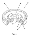
- FIG. 3 is a schematic 3-dimensional partially-sectioned view of viscoelastic reservoir, groove and fenestration elements (i.e., viscoelastic body elements) of FIGS. 1 and 2 showing the constrained area of the reservoir element where it contacts an adjustable preload flange, as well as an adjacent unconstrained area.
- viscoelastic reservoir, groove and fenestration elements i.e., viscoelastic body elements
- FIG. 4 is a schematic 3-dimensional partially-sectioned view of two check valve bodies with an adjustable preload flange located at different longitudinal positions on a central guide stem.
- FIG. 5 is a schematic 3-dimensional instantaneous partially-sectioned view of shear-thickening material which would, e.g., substantially fill a circular tubular area in the viscoelastic groove element and/or a support circular tubular area of a tunable valve seat or a tunable plunger seal.
- FIG. 6 is a schematic illustration of an exploded partially-sectioned 2-dimensional view of major components of a pump fluid end subassembly, together with brief explanatory comments on component functions.
- the schematically-illustrated subassembly comprises a pumping chamber within a subassembly pump housing, the pumping chamber being in fluid communication with a suction bore, a discharge bore, and a piston/plunger bore.
- Schematic representations of a suction check valve, a discharge check valve, and a piston/plunger are shown in their respective bores, together with brief annotations and graphical aids outlining the structural relationships.
- FIG. 7 is a schematic illustration of two views of an exploded partially-sectioned 3-dimensional view of a valve body and tunable valve seat embodiment. Curved longitudinal section edges of the valve body's convex valve seat interface and corresponding concave mating portions of the tunable valve seat are shown schematically in a detail breakout view to aid description herein of a rolling valve seal.
- a tunable (suction or discharge) check valve embodiment of the invention may comprise a combination of a tunable check valve assembly/tunable radial array (see, e.g., FIGS. 1 and 2 ) and a tunable valve seat (see, e.g., FIGS. 7 and 8 ).
- FIG. 8 is a schematic 3-dimensional exploded and partially-sectioned view of a tunable valve seat embodiment showing a concave mating surface longitudinally spaced apart from a lateral support mounting surface, and an adjustable lateral support assembly comprising first and second securable end spacers in combination with a plurality of circular viscoelastic support elements, each support element comprising a support circular tubular area.
- FIG. 9 is a schematic 3-dimensional exploded view of a partially sectioned tunable check valve assembly embodiment.
- a dilatant (i.e., shear-thickening) fluid is schematically shown being added to a check valve body's internal cavity, the cavity being shown as enclosing a tuned vibration damper comprising discrete mechanical elements (e.g., a mass and three springs).
- FIG. 10 is a schematic 3-dimensional exploded view of a tunable check valve embodiment comprising the tunable check valve assembly of FIG. 9 together with a tunable valve seat, the tunable check valve embodiment including structures to facilitate a rolling seal between the valve body's valve seat interface and the tunable valve seat's mating surface.
- the (convex) valve seat interface has correspondingly greater curvature than the (concave) mating surface, and the mating surface has correspondingly less curvature than the valve seat interface.
- FIG. 11 is a schematic 3-dimensional exploded view of an alternate tunable check valve embodiment comprising the tunable check valve assembly of FIG. 9 together with a tunable valve seat, the tunable check valve embodiment including structures to facilitate a rolling seal between the check valve body's peripheral valve seat interface and the tunable valve seat's mating surface.
- An adjustable lateral support assembly is shown with the tunable valve seat, the assembly comprising first and second securable end spacers in combination with a plurality of circular viscoelastic support elements, each support element shown in a detail breakout view as comprising a support circular tubular area.
- FIG. 12 illustrates two schematic 3-dimensional views of an alternate tunable check valve assembly embodiment comprising a plurality of radially-spaced vibration dampers disposed in a valve body having a peripheral seal.
- Each vibration damper comprises a circular tubular area, and at least one vibration damper is tunable via a fluid tuning medium (shown schematically being added) in a tubular area.
- the fluid tuning medium may comprise, e.g., one or more shear-thickening materials.
- FIG. 13 is a schematic 3-dimensional exploded view of the alternate tunable check valve assembly embodiment of FIG. 12 .
- Detail breakout views include the peripheral seal's medial flange and the flange body's corresponding flange channel.
- An instantaneous schematic view of the fluid tuning medium in the peripheral seal's circular tubular area is shown separately. Note that a portion of the circular tubular area (with its fluid tuning medium) extends into (i.e., is partially surrounded by) the peripheral seal's medial flange.
- FIG. 14 illustrates a partial schematic 3-dimensional view of an alternate tunable check valve embodiment comprising the valve body of FIGS. 12 and 13 , together with a tunable valve seat.
- a detail breakout view shows that the valve seat interface has correspondingly greater curvature than the mating surface.
- the mating surface has correspondingly less curvature than the valve seat interface to facilitate a rolling seal providing decreased contact area substantially along a circular line between the valve body's valve seat interface and the tunable valve seat's mating surface.
- Tunable fluid end embodiments comprise a family, each family member comprising a fluid-end housing with at least one installed tunable component chosen from: tunable check valve assemblies, tunable valve seats, tunable radial arrays and/or tunable plunger seals.
- Installing one or more tunable check valve assemblies facilitates selective attenuation of valve-generated vibration at its source. The likelihood of fluid end failures associated with fatigue cracking and/or corrosion fatigue is thereby reduced.
- Adding tunable valve seats, tunable radial arrays and/or plunger seals to tunable check valve assemblies in a fluid end further facilitates optimal damping and/or selective attenuation of vibration at one or more predetermined (and frequently-localized) fluid end resonant frequencies.
- Optimized vibration attenuation (via, e.g., optimized fluid end damping) is provided by altering resonant frequencies in each tunable component in relation to one or more (measured or estimated) fluid end resonant frequencies and/or tunable component resonant frequencies.
- a tunable (suction or discharge) check valve of the invention may comprise, for example, a combination of a tunable check valve assembly/tunable radial array 99 (see, e.g., FIG. 1 ) and a tunable valve seat 20 or a tunable valve seat 389 (see, e.g., FIGS. 7 and 11 ). Details of the structure and functions of each component are provided herein both separately and as combined with other components to obtain synergistic benefits contributing to longer pump service life.
- FIGS. 1 and 2 schematically illustrate an invention embodiment of a tunable check valve assembly/tunable radial array 99 substantially symmetrical about a longitudinal axis.
- Illustrated components include a valve body 10 , an adjustable preload flange 30 , and a plurality of viscoelastic body elements 50 .
- Check valve body 10 in turn, comprises a peripheral groove 12 (see FIG. 2 ) spaced apart by an annular (central) reservoir 16 from a longitudinal guide stem 14 , groove 12 being responsive to longitudinal compressive force.
- a plurality of viscoelastic body elements 50 comprises an annular (central) reservoir element 52 coupled to a (peripheral) groove element 54 by a plurality of (optional) radial fenestration elements 56 (in fenestrations 18 ) to form a tunable radial array.
- Groove element 54 functions as a vibration damper and valve seal, comprising at least one circular tubular area 58 .
- Responsiveness of groove 12 to longitudinal compressive force is characterized in part by damping of groove wall 11 / 13 / 15 vibrations. Such damping is due in part to out-of-phase vibrations in proximal groove wall 13 and distal groove wall 11 which are induced by longitudinal compressive force. Such out-of-phase vibrations will cause various groove-related dimensions to vary with longitudinal compressive force, thereby indicating the responsiveness of groove 12 to such force (see, for example, the dimension labeled A in FIG. 2 ).
- Each phase shift is associated with differences in the coupling of proximal groove wall 13 to guide stem 14 (indirectly via longitudinal groove wall 15 and radial reservoir floor 19 ) and the coupling of distal groove wall 11 to guide stem 14 (directly via radial reservoir floor 19 ).
- longitudinal groove wall 15 may comprise fenestrations 18 , thereby increasing the responsiveness of groove 12 to longitudinal compressive force on tunable check valve assembly 99 .
- adjustable preload flange 30 extends radially from guide stem 14 (toward peripheral reservoir wall 17 ) over, for example, about 20% to about 80% of viscoelastic reservoir element 52 (see FIG. 3 ). Adjustable preload flange 30 thus imposes an adjustable annular shear preload over an annular constrained area 62 of viscoelastic reservoir element 52 to achieve at least a first predetermined assembly resonant frequency substantially replicating a (similar) measured or estimated resonant frequency (e.g., a pump housing resonant frequency). Note that an adjacent annular unconstrained area 60 of viscoelastic reservoir element 52 remains open to pumped fluid pressure. Note also that adjustable preload flange 30 may be adjusted in effective radial extent and/or longitudinal position.
- annular constrained area 62 and annular unconstrained area 60 are substantially concentric and adjacent.
- annular unconstrained area 60 will tend to move (i.e., extrude) proximally relative to area 62 .
- the oppositely-directed (i.e., countercurrent) movements of constrained and unconstrained annular areas of viscoelastic reservoir element 52 create a substantially annular area of shear stress.
- each circular tubular area 58 is substantially filled with at least one shear-thickening material 80 (see FIG. 5 ) chosen to achieve at least a second predetermined assembly resonant frequency similar, for example, to the first predetermined assembly resonant frequency).
- FIG. 5 schematically represents a partially-sectioned view of an instantaneous configuration of the shear-thickening material 80 within circular tubular area 58 .
- a tunable check valve assembly/tunable radial array embodiment 99 comprises viscoelastic body elements 50 which comprise, in turn, reservoir (central) element 52 coupled to groove (peripheral) element 54 via radial fenestration (tension) elements 56 .
- Elements 52 , 54 and 56 are disposed in (i.e., integrated with and/or lie substantially in) reservoir 16 , groove 12 and fenestrations 18 respectively to provide a tuned radial array having at least a third predetermined resonant frequency.
- An adjustable preload flange 30 is coupled to guide stem 14 and contacts viscoelastic reservoir element 52 in reservoir 16 to impose an adjustable annular constraint on viscoelastic reservoir element 52 for achieving at least a first predetermined assembly resonant frequency substantially similar to, for example, a measured resonant frequency (e.g., a pump housing resonant frequency).
- a measured resonant frequency e.g., a pump housing resonant frequency
- Such adjustable annular constraint imposes an adjustable shear preload between constrained annular area 62 and unconstrained annular area 60 .
- Tunable check valve assembly 99 may additionally comprise at least one circular tubular area 58 in groove element 54 residing in groove 12 , each tubular area 58 being substantially filled with at least one shear-thickening material 80 chosen to achieve at least a second predetermined assembly resonant frequency similar, for example, to the first predetermined assembly resonant frequency).
- the above embodiment may be installed in a pump housing having a measured housing resonant frequency; the measured housing resonant frequency may then be substantially replicated in the (similar) first predetermined resonant frequency of the tunable check valve assembly.
- a combination would be an application of an alternate embodiment.
- An analogous tuning procedure may be followed if the tunable check valve assembly of the second embodiment is installed in a pump having a (similar or different) resonant frequency substantially equal to the second predetermined resonant frequency.
- This synergistic combination would broaden the scope of the valve assembly's beneficial effects, being yet another application of the invention's alternate embodiment.
- preload flange 30 may have a non-cylindrical periphery 32 for imposing on viscoelastic reservoir element 52 an adjustable annular shear preload having both longitudinal and transverse components.
- adjustable preload flange 30 if cylindrical, predisposes a tunable check valve assembly to substantially longitudinal shear damping with each longitudinal distortion of check valve body 10 associated with valve closure.
- the character of such shear damping depends, in part, on the longitudinal position of the preload flange. Examples of different longitudinal positions are seen in FIG. 4 , which schematically illustrates the flange 30 ′ longitudinally displaced from flange 30 ′′.
- the convex periphery of a longitudinally adjusted preload flange 30 ′ or 30 ′′ may introduce shear damping of variable magnitude and having both longitudinal and transverse components. Such damping may be beneficial in cases where significant transverse valve-generated vibration occurs.
- viscoelastic body elements 50 labels indicating the portions are placed on a sectional view in FIGS. 2 and 3 .
- Actual placement of viscoelastic body elements 50 in valve body 10 may be by, for example, casting viscoelastic body elements 50 in place, or placing viscoelastic body elements 50 (which have been precast) in place during layer-built or welded fabrication.
- the tunable check valve assembly embodiment of the invention is intended to represent check valve body 10 and viscoelastic body elements 50 as complementary components at any stage of manufacture leading to functional integration of the two components.
- shear-thickening material 80 and/or viscoelastic body elements 50 may comprise one or more polymers which have been augmented with nanoparticles and/or graphene 82 (see, e.g., FIG. 5 ).
- Nanoparticles and/or graphene may be invisible to the eye as they are typically dispersed in a colloidal suspension. Hence, they are schematically represented by cross-hatching 82 in FIG. 5 .
- Nanoparticles may comprise, for example, carbon forms (e.g., graphene) and/or metallic materials such as copper, beryllium, titanium, nickel, iron, alloys or blends thereof.
- the term nanoparticle may conveniently be defined as including particles having an average size of up to about 2000 nm. See, e.g., the '320 patent.
- FIG. 6 is a schematic illustration of an exploded partially-sectioned 2-dimensional view of major components of a pump fluid end subassembly 88 , together with graphical aids and brief explanatory comments on component functions.
- the schematically-illustrated subassembly 88 comprises a pumping chamber 74 within a subassembly (pump) housing 78 , the pumping chamber 74 being in fluid communication with a suction bore 76 , a discharge bore 72 , and a piston/plunger bore 70 .
- piston/plunger bore 70 comprises at least one recess (analogous to that labeled “packing box” in FIG. 6 ) in which at least one lateral support assembly 130 (see FIG.
- tunable suction valve 95 (illustrated for simplicity as a hinged check valve), a tunable discharge valve 97 (also illustrated for simplicity as a hinged check valve), and a piston/plunger 93 (illustrated for simplicity as a plunger) are shown in their respective bores.
- longitudinally-moving valve bodies in check valve embodiments schematically illustrated herein e.g., valve body 10
- certain operational phenomena analogous to phenomena seen in hinged check valves including, e.g., structural compliance secondary to closing energy impulses).
- the double-ended arrows that signify fluid communication between the bores (suction, discharge and piston/plunger) and the pumping chamber are double-ended to represent the fluid flow reversals that occur in each bore during each transition between pressure stroke and suction stroke of the piston/plunger.
- the large single-ended arrow within the pumping chamber is intended to represent the periodic and relatively large, substantially unidirectional fluid flow from suction bore through discharge bore during pump operation.
- tunable suction (check) valve 95 and tunable discharge (check) valve 97 are shown schematically as hinged check valves in FIG. 6 because of the relative complexity of check valve embodiments having longitudinally-moving valve bodies. More detailed schematics of several check valve assemblies and elements are shown in FIGS. 1-11 , certain tunable check valve embodiments comprising a tunable check valve assembly and a tunable valve seat.
- the tunable check valve assemblies/tunable radial arrays of tunable suction and discharge valves will typically be tuned to different assembly resonant frequencies because of their different positions in a subassembly housing 78 (and thus in a pump housing as described herein). Pump housing resonant frequencies that are measured proximate the tunable suction and discharge valves will differ in general, depending on the overall pump housing design. In each case they serve to guide the choices of the respective assembly resonant frequencies for the valves.
- FIG. 6 the combination of major components labeled in FIG. 6 as a pump fluid end subassembly 88 is so labeled (i.e., is labeled as a subassembly) because typical fluid end configurations comprise a plurality of such subassemblies combined in a single machined block.
- the housing is simply termed a “pump housing” rather than the “subassembly housing 78 ” terminology of FIG. 6 .
- each pump fluid end subassembly 88 comprises only major components: a pumping chamber 74 , with its associated tunable suction valve 95 , tunable discharge valve 97 , and piston/plunger 93 in their respective bores 76 , 72 and 70 of subassembly housing 78 .
- a pumping chamber 74 with its associated tunable suction valve 95 , tunable discharge valve 97 , and piston/plunger 93 in their respective bores 76 , 72 and 70 of subassembly housing 78 .
- common fluid end features well-known to those skilled in the art are not shown.
- a common suction manifold through which incoming pumped fluid is distributed to each suction bore 76 and a common discharge manifold for collecting and combining discharged pumped fluid from each discharge bore 72 , are also well-known to those skilled in the art and thus are not shown.
- FIG. 6 the desired check-valve function of tunable check valves 95 and 97 schematically-illustrated in FIG. 6 requires interaction of the respective tunable check valve assemblies (see, e.g., FIGS. 1-5 ) with a corresponding (schematically-illustrated) tunable valve seat (see, e.g., FIGS. 7 , 8 , 10 and 11 ).
- the schematic illustrations of FIG. 6 are only intended to convey general ideas of relationships and functions of the major components of a pump fluid end subassembly. Structural details of the tunable check valve assemblies that are in turn part of tunable check valves 95 and 97 of the invention (including their respective tunable valve seats) are illustrated in greater detail in other figures as noted above. Such structural details facilitate a plurality of complementary functions that are best understood through reference to FIGS. 1-5 and 7 - 11 .
- tunable check valves include, but are not limited to, closing energy conversion to heat via structural compliance, energy redistribution through rejection of heat to the pumped fluid and pump housing, vibration damping and/or selective vibration spectrum narrowing through changes in tunable check valve assembly compliance, vibration frequency down-shifting (via decrease in rebound characteristic frequency) through increase of rebound cycle time, and selective vibration attenuation through energy dissipation (i.e., via redistribution) at predetermined assembly resonant frequencies.
- FIG. 7 is a schematic illustration of two views of an exploded partially-sectioned 3-dimensional view including a check valve body 10 and its convex valve seat interface 22 , together with concave mating surface 24 of tunable valve seat 20 .
- Mating surface 24 is longitudinally spaced apart from a pump housing interface surface 21 .
- a curved longitudinal section edge 28 of the tunable valve seat's mating surface 24 together with a correspondingly greater curved longitudinal section edge 26 of the valve body's valve seat interface 22 , are shown schematically in detail view A to aid description herein of a rolling valve seal.
- valve seat interface 22 As compared to the curvature of mating surface 24 , effectively provides a rolling seal against fluid leakage which reduces wear on the surfaces in contact.
- the rolling seal also increases longitudinal compliance of a tunable suction or discharge valve of the invention, with the added benefit of increasing the rise and fall times of the closing energy impulse (thus narrowing the associated vibration spectrum). Widening the closing energy impulse increases rebound cycle time and correspondingly decreases rebound characteristic frequency.
- valve seat interface 22 and mating surface 24 are chosen so that the degree of longitudinal curvature of valve seat interface 22 (including edge 26 ) exceeds that of (i.e., has correspondingly greater curvature than) mating surface 24 (including edge 28 ) at any point of rolling contact.
- mating surface 24 (including edge 28 ) has correspondingly less curvature than valve seat interface 22 (including edge 26 ).
- rolling contact i.e., a rolling valve seal
- mating surface 24 is a curved mating surface for providing decreased contact area along the circular line.
- the plane of the circular line is generally transverse to the (substantially coaxial) longitudinal axes of valve body 10 and tunable valve seat 20 .
- Description of such a contact area herein as decreased contact area refers to comparison of the narrow contact area (i.e., along a substantially circular line) inherent in a rolling valve seal in relation to the relatively broad contact area theoretically available between the nominally frusto-conical contact surfaces of a conventional valve seat interface and a corresponding frusto-conical valve seat.
- valve seat interface 22 and mating surface 24 are schematically illustrated as curved, either may be frusto-conical (at least in part) in certain tuned component embodiments.
- Such frusto-conical embodiments may have lower fabrication costs and may exhibit suboptimal distortion, down-shifting performance and/or wear characteristics. They may be employed in relatively lower-pressure applications where other tunable component characteristics provide sufficient operational advantages in vibration control.
- FIG. 8 schematically illustrates a 3-dimensional exploded and partially-sectioned view of a tunable valve seat showing a mating surface (analogous to mating surface 24 of FIG. 7 ) longitudinally spaced apart from a lateral support mounting surface 21 ′.
- the lateral support mounting surface 21 ′ in FIG. 8 differs from pump housing interface surface 21 of FIG. 7 in that it facilitates adjustably securing a lateral support assembly 130 to alternate tunable valve seat 20 ′.
- Lateral support assembly 130 comprises first and second securable end spacers ( 110 and 124 respectively) in combination with a plurality of circular viscoelastic support elements ( 114 , 118 and 122 ), each support element comprising a support circular tubular area (see areas 112 , 116 and 120 respectively). Shear-thickening material in each support circular tubular area 112 , 116 and 120 is chosen so each lateral support assembly 130 has at least one predetermined resonant frequency. Lateral support assemblies thus configured may be part of each tunable valve seat and each tunable plunger seal.
- one or more lateral support assemblies 130 reside in at least one recess analogous to the packing box schematically illustrated adjacent to piston/plunger 93 (i.e., as a portion of piston/plunger bore 70 ) in FIG. 6 .
- a tunable (suction or discharge) check valve of the invention may comprise a combination of a tunable check valve assembly 99 (see, e.g., FIG. 1 ) and a tunable valve seat 20 (see, e.g., FIG. 7 ) or a tunable valve seat 20 ′ (see, e.g., FIG. 8 ).
- tunable suction check valve 95 is distinguished from tunable discharge check valve 97 by one or more factors, including each measured resonant frequency to which each tunable check valve is tuned so as to optimize the overall effectiveness of valve-generated vibration attenuation in the associated pump housing 78 .
- FIGS. 9-11 show schematic exploded views of a nonlinear spring-mass damper 227 / 228 / 229 / 230 , which may be incorporated in a tunable check valve assembly embodiment 210 .
- FIGS. 9-11 can each be understood as schematically illustrating a tunable check valve assembly with or without a peripheral groove viscoelastic element. That is, each figure may also be understood to additionally comprise a viscoelastic groove element analogous to groove element 54 (see FIG. 2 ) residing in groove 218 ′/ 218 ′′ (see FIG. 9 )—this groove element is not shown in exploded FIGS.
- each tubular area 58 being substantially filled with at least one shear-thickening material 80 chosen to achieve at least one predetermined assembly resonant frequency.
- Belleville springs 227 / 228 / 229 are nonlinear, and they couple mass 230 to the valve body base plate 216 and the proximal valve body portion 214 . Additionally, dilatant fluid (i.e., fluid tuning medium) 242 is optionally added (via sealable ports 222 and/or 220 ) to central internal cavity 224 to immerse nonlinear spring-mass damper 227 / 228 / 229 / 230 .
- dilatant fluid i.e., fluid tuning medium
- fluid tuning medium 242 in shear expands the range of tuning the nonlinear spring-mass damper 227 / 228 / 229 / 230 to a larger plurality of predetermined frequencies to reduce “ringing” of valve body 214 / 216 in response to a closing energy impulse.
- mass 230 is shown perforated centrally to form a washer shape and thus provide a passage for flow of fluid tuning medium 242 during longitudinal movement of mass 230 .
- This passage is analogous to that provided by each of the Belleville springs 227 / 228 / 229 by reason of their washer-like shape.
- FIG. 10 shows an exploded view of an alternate embodiment of a tunable check valve comprising the tunable check valve assembly 210 of FIG. 9 , plus a tunable valve seat 250 .
- FIGS. 10 and 11 schematically illustrate two views of an exploded partially-sectioned 3-dimensional view including a valve body 214 / 216 and its valve seat interface 234 , together with mating surface 254 of tunable valve seats 250 and 250 ′.
- Mating surface 254 is longitudinally spaced apart from pump housing interface surface 252 in FIG. 10 , and from lateral support mounting surface 252 ′ in FIG. 11 .
- FIG. 10 shows an exploded view of an alternate embodiment of a tunable check valve comprising the tunable check valve assembly 210 of FIG. 9 , plus a tunable valve seat 250 .
- FIGS. 10 and 11 schematically illustrate two views of an exploded partially-sectioned 3-dimensional view including a valve body 214 / 216 and its valve seat interface 234 , together with mating
- a curved longitudinal section edge 256 of the tunable valve seat's mating surface 254 together with a correspondingly greater curved longitudinal section edge 236 of valve seat interface 234 , are shown schematically to aid description herein of a rolling valve seal.
- valve body 214 / 216 may be fabricated by several methods, including that schematically illustrated in FIGS. 9-11 .
- circular boss 215 on proximal valve body portion 214 may be inertia welded or otherwise joined to circular groove 217 on valve body base plate 216 .
- Such joining results in the creation of peripheral seal-retention groove 218 ′/ 218 ′′ having proximal groove wall 218 ′ and distal groove wall 218 ′′.
- fluid polymer(s) in fluid tuning medium 242 may be augmented by adding nanoparticles which are generally invisible to the eye as they are typically dispersed in a colloidal suspension.
- Nanoparticles comprise, for example, carbon and/or metallic materials such as copper, beryllium, titanium, nickel, iron, alloys or blends thereof.
- the term nanoparticle may conveniently be defined as including particles having an average size of up to about 2000 nm. See, e.g., the '320 patent.
- valve seat interface 234 As compared to the curvature of mating surface 254 , effectively provides a rolling seal against fluid leakage which reduces frictional wear on the surfaces in contact.
- the rolling seal also increases longitudinal compliance of a tunable suction or discharge valve of the invention, with the added benefit of increasing the rise and fall times of the closing energy impulse (thus narrowing the associated vibration spectrum).
- curvatures of the schematically illustrated longitudinal section edges (i.e., 236 and 256 ) and the surfaces of which they are a part (i.e., valve seat interface 234 and mating surface 254 respectively) are chosen so that the degree of longitudinal curvature of valve seat interface 234 (including edge 236 ) exceeds that of (i.e., has correspondingly greater curvature than) mating surface 254 (including edge 256 ) at any point of rolling contact.
- valve seat interface 234 and mating surface 254 rolling contact between valve seat interface 234 and mating surface 254 is always along a substantially circular line that decreases contact area relative to the (potentially variable) contact area of a (potentially distorted) conventional frusto-conical valve body/valve seat interface (see discussion above).
- the plane of the circular line is generally transverse to the (substantially coaxial) longitudinal axes of valve body 214 / 216 and tunable valve seat 250 . (See notes above re frusto-conical valve seat interface shapes and mating surfaces).
- Lateral support assembly 330 comprises first and second securable end spacers ( 310 and 324 respectively) in combination with a plurality of circular viscoelastic support elements ( 314 , 318 and 322 ), each support element comprising a support circular tubular area ( 312 , 316 and 320 respectively).
- a tunable (suction or discharge) check valve of the invention may comprise a combination of a tunable check valve assembly 210 (see, e.g., FIG. 9 ) and a tunable valve seat 250 (see, e.g., FIG. 10 ) or a tunable valve seat 250 ′ (see, e.g., FIG. 11 ).
- tunable suction valve 95 is distinguished from tunable discharge check valve 97 by one or more factors, including each measured or estimated resonant frequency to which each tunable check valve is tuned so as to optimize the overall effectiveness of valve-generated vibration attenuation in the associated pump housing 78 .
- FIGS. 12-14 illustrate schematic 3-dimensional partially-sectioned views of an alternate tunable check valve assembly embodiment 442 / 410 / 470 / 480 (see, e.g., FIG. 12 and exploded view FIG. 13 ) which is symmetrical about a longitudinal axis and comprises a plurality of radially-spaced vibration dampers (i.e., a tuned radial array of vibration dampers).
- One such damper i.e., a peripheral damper
- tubular area 472 / 474 is responsive to longitudinal compression of the assembly (as, for example, by proximal fluid pressure due to a pump pressure stroke).
- Responsiveness to longitudinal compression is secondary, e.g., to compression of peripheral seal 470 against a valve seat 450 (see, e.g., FIG. 14 ) and/or to alteration of the shape of peripheral seal groove 418 (imposed on peripheral seal 470 ) due to relative movement of proximal and distal groove walls 418 ′ and 418 ′′ during assembly longitudinal compression (see, e.g., FIG. 13 ).
- a second damper i.e., a central damper
- valve body 410 it comprises enclosed spaces 460 / 464 in fluid communication with central circular tubular area 462 via fluid flow restrictors 466 / 468 .
- central circular tubular area 462 and fluid flow restrictors 466 / 468 are responsive to longitudinal to compression of the assembly, due, e.g., to cyclically reversible reductions of the internal volumes of tubular area 462 and area 464 .
- Such temporary volume reductions in areas 462 / 464 prompt flow of fluid tuning medium 442 through the flow restrictors 466 / 468 to surge chamber 460 in association with valve closure shock and/or vibration.
- Such flow of fluid tuning medium 442 reverses with each cycle of longitudinal compression.
- each of the radially-spaced (peripheral and central) vibration dampers comprises a circular tubular area (e.g., tubular areas 472 / 474 and 462 respectively), and at least one vibration damper is tunable to a predetermined frequency (e.g., a resonant frequency of a fluid end in which the assembly is installed).
- the tuning mechanisms may differ: e.g., via a fluid tuning medium 442 (shown schematically being added in FIG. 12 via a sealable port 422 (see FIG.
- fluid tuning medium might also or alternatively be added via sealable port 420 in (distal) base plate 416 .
- proximal valve body portion 414 in FIG. 13 is separately identified to call attention to the possibility of fabricating base plate 416 and proximal portion 414 separately and then welding them together to form valve body 410 .
- the terms proximal and distal in this paragraph assume a suction valve configuration; in a discharge valve configuration the positions of the terms would be reversed.
- tuning is function of responsiveness of the respective dampers to vibration secondary to valve closure impact (see above discussion of the vibration spectrum of an impulse).
- longitudinal force on the closed valve will tend to reduce the distance between opposing fluid flow restrictors 466 / 468 , simultaneously prompting flow of fluid tuning medium 442 from circular tubular area 462 to areas 464 and/or 460 ( 460 acting as a surge chamber).
- Flow resistance will be a function of fluid flow restrictors 466 / 468 and the fluid viscosity.
- viscosity may vary with time in a shear-thickening fluid which may be present in fluid tuning medium 442 , thereby introducing nonlinearly for predictably altering center frequency and/or Q of the damper.
- Analogous predetermined viscosity variation in fluid tuning medium 482 is available for predictably altering the center frequency and/or Q (i.e., altering the tuning) of the peripheral damper 470 / 472 / 474 / 480 as the seal 470 distorts under the longitudinal compressive load of valve closure.
- peripheral seal vibration damper 470 / 472 / 474 / 480 comprises a medial flange 479 sized to closely fit within flange channel 419 of valve body 410 .
- See detail breakout view A of FIG. 13 showing flange channel 419 and a generic peripheral valve seat interface 434 for sealing against a generic valve seat mating surface 454 .
- See detail breakout view B of FIG. 13 showing medial flange 479 partially surrounding portion 474 of circular tubular area 472 / 474 within seal 470 .
- conventional peripheral seals tend to rotate within their retaining groove as a valve body (with its peripheral seal) mates with a valve seat.
- the illustrated seal embodiment herein shows that such rotation will tend to be resisted by the combined action of medial flange 479 and flange channel 419 .
- the portion 474 of circular tubular area 472 / 474 (portion 474 being partially surrounded by flange channel 419 ) will tend to stiffen medial flange 479 in a nonlinear manner.
- Such stiffening of medial flange 479 may be due in part to the presence of shear-thickening fluid in fluid tuning medium 480 (and particularly the medial region 484 thereof) in circular tubular area 472 / 474 .
- a schematically illustrated example (see FIG. 13 ) of circular tubular area 472 / 474 is shown as containing fluid tuning medium 480 (fluid tuning medium regions 482 / 484 being shown as having an overall instantaneous shape 480 ).
- FIG. 14 illustrates a partial schematic 3-dimensional view of an alternate tunable check valve embodiment comprising the valve body 410 of FIG. 13 , together with a tunable valve seat 452 .
- Detail breakout view A of FIG. 14 shows a specialized version of a peripheral valve seat interface 436 , the specialized version of the valve seat interface 436 having correspondingly greater curvature than the specialized valve seat mating surface 456 which is configured to facilitate a rolling valve seal for providing decreased contact area along a circular line.
- the rolling valve seal thus formed has a predetermined rebound cycle time and rebound characteristic frequency as described elsewhere herein.
Abstract
Tunable check valves reduce valve-generated vibration to increase the reliability of tunable fluid ends. Selected improved designs described herein reflect disparate applications of identical technical principles (relating to, e.g., the vibration spectrum of an impulse). Tunable check valve embodiments comprise a family including, but not limited to, tunable check valve assemblies, tunable valve seats, and tunable radial arrays. Each such tunable embodiment, in turn, contributes to blocking excitation of fluid end resonances, thus reducing the likelihood of fluid end failures associated with fatigue cracking and/or corrosion fatigue. By down-shifting the frequency domain of each valve-closing impulse shock, initial excitation of fluid end resonances is minimized. Subsequent damping and/or selective attenuation of vibration likely to excite one or more predetermined (and frequently localized) fluid end resonances represents further optimal use of fluid end vibration-control resources for improving high-pressure fluid end reliability.
Description
The invention relates generally to reciprocating pumps, and more specifically to vibration and vibration effects in such pumps.
Reciprocating high-pressure pumps (commonly called fracking, frac or well-service pumps) are often used in oil and gas fields for hydraulic fracturing of rock formations to increase hydrocarbon yields. Such pumps are typically truck-mounted for easy relocation from well-to-well. And they are usually designed in two sections: the (proximal) power section (herein “power end”) and the (distal) fluid section (herein “fluid end”). Each pump fluid end comprises at least one subassembly (and commonly three or more in a single fluid end housing), with each subassembly comprising a suction valve, a discharge valve, a plunger or piston, and a portion of (or substantially the entirety of) a pump fluid end subassembly housing (shortened herein to “pump housing” or “fluid end housing” or “housing” depending on the context).
For each pump fluid end subassembly, its fluid end housing comprises a pumping chamber in fluid communication with a suction bore, a discharge bore, and a piston/plunger bore. A suction valve (i.e., a check valve) within the suction bore, together with a discharge valve (i.e., another check valve) within the discharge bore, control bulk fluid movement from suction bore to discharge bore via the pumping chamber. Note that the term “check valve” as used herein refers to a valve in which a (relatively movable) valve body can reversibly close upon a (relatively stationary) valve seat to achieve substantially unidirectional bulk fluid flow through the valve.
Pulsatile fluid flow through the pump results from periodic pressurization of the pumping chamber by a reciprocating plunger or piston within the plunger/piston bore. Suction and pressure strokes alternately produce wide pressure swings in the pumping chamber (and across the suction and discharge check valves) as the reciprocating plunger or piston is driven by the pump power end.
Such pumps are rated at peak pumped-fluid pressures in current practice up to about 22,000 psi, while simultaneously being weight-limited due to the carrying capacity of the trucks on which they are mounted. (See, e.g., U.S. Pat. No. 7,513,759 B1, incorporated by reference).
Due to high peak pumped-fluid pressures, suction check valves experience particularly wide pressure variations between a suction stroke, when the valve opens, and a pressure stroke, when the valve closes. For example, during a pressure stroke with a rod load up to 350,000 pounds, a conventionally rigid/heavy check valve body may be driven longitudinally (by pressurized fluid proximal to it) toward metal-to-metal impact on a conventional frusto-conical valve seat at closing forces of about 50,000 to over 250,000 pounds (depending on valve dimensions). Total check valve-closure impact energy (i.e., the total kinetic energy of the moving valve body and fluid at valve seat impact) is thus converted to a short-duration high-amplitude valve-closure impulse (i.e., a mechanical shock). Repeated application of such a valve-closure shock with each pump cycle predisposes the check valve, and the fluid end housing in which it is installed, to vibration-induced (e.g., fatigue) damage. Cumulative shocks thus constitute a significant liability imposed on frac pump reliability, proportional in part to the rigidity and weight of the check valve body.
The emergence of new frac pump reliability issues (e.g., failures secondary to vibration-induced fatigue cracks) has paralleled the inexorable rise of peak pumped-fluid pressures in new fracking applications. And insight into these new pump failure modes can be gained through review of earlier shock and vibration studies, data from which are cited herein. For example, a recent treatise on the subject describes a mechanical shock “ . . . in terms of its inherent properties, in the time domain or in the frequency domain; and . . . in terms of the effect on structures when the shock acts as the excitation.” (see p. 20.5 of Harris' Shock and Vibration Handbook, Sixth Edition, ed. Allan G. Piersol and Thomas L. Paez, McGraw Hill (2010), hereinafter Harris). The above time and frequency domains are mathematically represented on opposite sides of equations generally termed Fourier transforms. And estimates of a shock's structural vibration effects are frequently described in terms of two parameters: (1) the structure's undamped natural frequency and (2) the fraction of critical structural damping or, equivalently, the resonant gain Q (see Harris pp. 7.6, 14.9-14.10, 20.10). (See also, e.g., U.S. Pat. No. 7,859,733 B2, incorporated by reference).
Mathematical representations of time and frequency domain data play important roles in computer-assisted analysis of mechanical shock. In addition, shock properties are also commonly represented graphically as time domain impulse plots (e.g., acceleration vs. time) and frequency domain vibration plots (e.g., spectrum amplitude vs. frequency). Such graphical presentations readily illustrate the shock effects of metal-to-metal valve-closure, wherein longitudinal movement of a check valve body is abruptly stopped by a valve seat. Relatively high acceleration values and broad vibration spectra are prominent, each valve-closure impulse response primarily representing a violent conversion of kinetic energy to other energy forms.
Since energy cannot be destroyed, and since a conventional valve can neither store nor convert (i.e., dissipate) more than a small fraction of the valve-closure impulse's kinetic energy, most of that energy is necessarily transmitted to the pump (or fluid end) housing. In a time domain plot, the transmitted energy appears as a high-amplitude impulse of short duration. And a corresponding frequency domain plot of transmitted energy reveals a broad-spectrum band of high-amplitude vibration. This means that nearly all of the check valve's cyclical valve-closure kinetic energy is converted to vibration energy. The overall effects of check valve closures may thus be compared to the mechanical shocks that would result from striking the valve seat repeatedly with a commercially-available impulse hammer, each hammer strike being followed by a rebound. Such hammers are easily configured to produce relatively broad-spectrum high-amplitude excitation (i.e., vibration) in an object struck by the hammer. (See, e.g., Introduction to Impulse Hammers at http://dytran.com/img/tech/all.pdf, and Harris p. 20.10).
Summarizing then, relatively broad-spectrum high-amplitude vibration predictably results from a typical high-energy valve-closure impulse. And frac pumps with conventionally-rigid valves can suffer hundreds of these impulses per minute. Note that the number of impulses per minute (for example, 300 impulses per minute) corresponds to pump plunger strokes or cycles, and this number may be converted to impulses-per-second (i.e., 300/60=5). The number 5 is sometimes termed a frequency because it is given the dimensions of cycles/second or Hertz (Hz). But the “frequency” thus attributed to pump cycles themselves differs from the spectrum of vibration frequencies resulting from each individual pump cycle impulse. The difference is that impulse-generated (e.g., valve-generated) vibration occurs in bursts of broad spectra which may simultaneously contain many vibration frequencies ranging from a few Hz to several thousand Hz (kHz).
Nearly all of this (generally-higher frequency) valve-generated vibration energy is quickly transmitted to proximate areas of the fluid end or pump housing, where it can be expected to excite damaging resonances that predispose the housing to fatigue failures. (See, e.g., U.S. Pat. No. 5,979,242, incorporated by reference). If, as expected, a natural resonance frequency of the housing coincides with a frequency within the valve-closure vibration spectrum, fluid end vibration amplitude may be substantially increased and the corresponding vibration fatigue damage made much worse. (See Harris, p. 1.3).
Opportunities to limit fluid end damage begin with experiment-based redesign to control vibration fatigue. For example, a spectrum of vibration frequencies initially applied to a fluid end as a test can reveal structural resonance frequencies likely to cause trouble. Specifically, the applied vibration of a half-sine shock pulse of duration one millisecond has predominant spectral content up to about 2 kHz (see Harris, p. 11.22), likely overlapping a plurality of fluid end housing natural frequencies. Such tests particularly focus attention on blocking progression of fatigue crack growth to the critical size for catastrophic fracture. Note that stronger housings aren't necessarily better in such cases, since increasing the housing's yield strength causes a corresponding decrease in critical crack size. (See Harris, p. 33.23).
It might be assumed that certain valve redesigns proposed in the past (including relatively lighter valve bodies) would have alleviated at least some of the above failure modes. (See, e.g., U.S. Pat. No. 7,222,837 B1, incorporated by reference). But such redesigns emerged (e.g., in 2005 or earlier) when fluid end peak pressures were generally substantially lower than they currently are. In relatively lower pressure applications (e.g., mud pumps), rigid/heavy valve bodies performed well because the valve-closure shocks and associated valve-generated vibration were less severe compared to shock and vibration experienced more recently in higher pressure applications (e.g., fracking). Thus, despite their apparent functional resemblance to impulse hammers, relatively rigid/heavy valves have been pressed into service as candidates for use in frac pump fluid ends. Indeed, they have generally been the only valves available in commercial quantities during the recent explosive expansion of well-service fracking operations. Substantially increased fluid end failure rates (due, e.g., to cracks near a suction valve seat deck) have been among the unfortunate, and unintended, consequences.
Under these circumstances, it is regrettable but understandable that published data on a modern 9-ton, 3000-hp well-service pump includes a warranty period measured in hours, with no warranty for valves or weld-repaired fluid ends.
Such baleful vibration-related results in fluid ends might usefully be compared with vibration-related problems seen during the transition from slow-turning two-cylinder automobile engines to higher-speed and higher-powered inline six-cylinder engines around the years 1903-1910. Important torsional-vibration failure modes suddenly became evident in new six-cylinder engines, though they were neither anticipated nor understood at the time. Whereas the earlier engines had been under-powered but relatively reliable, torsional crankshaft vibrations in the six-cylinder engines caused objectionable noise (“octaves of chatter from the quivering crankshaft”) and unexpected catastrophic failures (e.g., broken crankshafts). (Quotation cited on p. 13 of Royce and the Vibration Damper, Rolls-Royce Heritage Trust, 2003). Torsional-vibration was identified as the culprit and, though never entirely eliminated, was finally reduced to a relatively minor maintenance issue after several crankshaft redesigns and the development of crankshaft vibration dampers pioneered by Royce and Lanchester.
Reducing the current fluid end failure rates related to valve-generated vibration in frac pumps requires an analogous modern program of intensive study and specific design changes. The problem will be persistent because repeatedly-applied valve-closure energy impulses cannot be entirely eliminated in check-valve-based fluid end technology. So the valve-closing impulses must be modified, and their associated vibrations damped, to reduce excitation of destructive resonances in valves, pump housings, and related fluid end structures. Alternate materials, applied via innovative designs, illuminate the path forward now as they have in the past. Broad application of such improvements promises higher frac pump reliability, an important near-term goal. Simultaneously, inhibition of corrosion fatigue throughout analogous fluid circuits would be advanced, a longer-term benefit in refineries, hydrocarbon crackers and other industrial venues that are also subjected to shock-related vibration.
Tunable check valves reduce valve-generated vibration to increase the reliability of tunable fluid ends. Selected improved designs described herein reflect disparate applications of identical technical principles (relating to, e.g., the vibration spectrum of an impulse). Tunable check valve embodiments comprise a family including, but not limited to, tunable check valve assemblies, tunable valve seats, and tunable radial arrays. Each such tunable embodiment, in turn, contributes to blocking excitation of fluid end resonances, thus reducing the likelihood of fluid end failures associated with fatigue cracking and/or corrosion fatigue. By down-shifting the frequency domain of each valve-closing impulse shock, initial excitation of fluid end resonances is minimized. Subsequent damping and/or selective attenuation of vibration likely to excite one or more predetermined (and frequently localized) fluid end resonances represents further optimal use of fluid end vibration-control resources for improving high-pressure fluid end reliability.
Frequency domain down-shifting and damping both assist vibration control by converting valve-closure energy to heat and dissipating it in each tunable component present in a tunable fluid end embodiment. Effects of down-shifting on a valve-closure impulse shock include frequency-selective spectrum-narrowing that is easily seen in the frequency domain plot of each shock. That is, down-shifting effectively attenuates and/or limits the bandwidth(s) of valve-generated vibration. Subsequent (coordinated) damping assists in converting a portion of this band-limited vibration to heat.
Both down-shifting and damping are dependent in part on constraints causing shear-stress alteration (that is, “tuning”) imposed on one or more viscoelastic and/or shear-thickening elements in each tunable component. Additionally, hysteresis or internal friction (see Harris, p. 5.7) associated with mechanical compliance of certain structures (e.g., valve bodies or springs) may aid damping by converting vibration energy to heat (i.e., hysteresis loss). (See Harris, p. 2.18).
Tunable component resonant frequencies may be shifted (or tuned) in a coordinated manner to approximate predetermined values corresponding to measured or estimated pump or fluid-end resonant frequencies (herein termed “critical” frequencies). Such coordinated tuning predisposes valve-generated vibration at critical frequencies to excite the tunable component (and thus be damped and dissipated as heat) rather than exciting the fluid end (e.g., the fluid end housing) itself. This reduces the likelihood of fluid end failures due, e.g., to vibration-induced fatigue cracks).
To complement the above coordinated damping, frequency down-shifting functions to reduce the total amount of critical frequency vibration requiring damping. Such down-shifting is activated through designs enhancing mechanical compliance. In continuous pump operation, mechanical compliance is manifest, for example, in elastic valve body flexures secondary to repetitive longitudinal compressive forces (i.e., plunger pressure strokes) of the valve body against the valve seat. Each such flexure is followed by a hysteresis-limited elastic rebound of the valve body from the valve seat. The duration of the entire flexure-rebound interval (i.e., a cycle) is termed herein “rebound cycle time” and is measured in seconds. The inverse of rebound cycle time has the dimensions of frequency and is termed herein “rebound characteristic frequency.” Cumulative rebound cycle energy loss in the form of heat (e.g., hysteresis loss plus friction loss) is continuously transported for redistribution within the valve body and eventual rejection to the valve body surroundings (including, e.g., the pumped fluid). This heat loss represents a reduction in the total available energy content (and thus the damage-causing potential) of the valve-closure energy impulse.
Note that lengthening rebound cycle time to beneficially narrow the valve-generated vibration spectrum is accomplished in various invention embodiments using mechanical/hydraulic/pneumatic analogs of electronic wave-shaping techniques. For example, lengthened rebound cycle time is substantially influenced by the tunable valve assembly's increased longitudinal compliance associated with rolling seal contact (i.e., comprising valve body flexure and rebound) described herein, e.g., as between a tunable check valve body's peripheral valve seat interface and a tunable valve seat's mating surface.
Briefly summarizing, as each tunable component present in a tunable fluid end embodiment absorbs, converts and redistributes (i.e., dissipates) a portion of valve closing impulse shock energy, only a fraction of the original closing impulse energy remains at critical frequencies capable of exciting destructive resonant frequencies in the fluid end. Following vibration down-shifting, a significant portion of valve-closure energy has been shifted to lower frequency vibration through structural compliance as described above. This attenuated vibration is then selectively damped (i.e., dissipated as heat) at shifted frequencies via one or more of the tunable components. While tunable components may be relatively sharply tuned (e.g., to act as tuned mass dampers for specific frequencies), they may alternately be more broadly tuned to account for a range of vibration frequencies encountered in certain pump operations. Flexibility in tuning procedures, as described herein with material and adjustment choices, is therefore frequently desirable.
Note that vibration absorption at specific frequencies (e.g., via dynamic or tuned absorbers) may have limited utility in conventional frac pumps because of the varying speeds at which the pumps operate and the relatively broad bandwidths associated with valve-closing impulse shocks. In contrast, the process of down-shifting followed by damping in tunable fluid ends is more easily adapted to changes inherent in the pumps' operational environment. Damping may nevertheless be added to a dynamic absorber to increase its effective frequency range for certain applications. (See, e.g., tuned vibration absorber and tuned mass damper in ch. 6 of Harris).
Selective damping of vibration frequencies near the resonant frequencies of fluid ends is desirable for the same reason that soldiers break step when they march over a bridge—because even relatively small amounts of vibration energy applied at the bridge's resonant frequency can cause catastrophic failure. Similar reasoning underlies the functions of selective vibration down-shifting and damping in tunable fluid ends. Various combinations of the tunable components described herein are particularly beneficial because they focus the functions of vibration-limiting resources on minimization of vibration energy present in a fluid end near its critical frequencies. Cost and complexity of tunable components are thus minimized while the efficacy of each tunable component's function (i.e., vibration limitation at particular frequencies) is enhanced. Stated another way, a tunable component's selective vibration down-shifting and damping are optimized using metrics including cost, complexity, and damping factor (or degree of damping).
Note that a variety of optimization strategies for vibration attenuation and damping may be employed in specific cases, depending on parameters such as the Q (or quality) factor attributable to each fluid end resonance. The fluid end response to excitation of a resonance may be represented graphically as, for example, a plot of amplitude vs. frequency. Such a Q response plot typically exhibits a single amplitude maximum at the local fluid end resonance frequency, with decreasing amplitude values at frequencies above and below the resonance. At an amplitude value about 0.707 times the maximum value (i.e., the half-power point), the amplitude plot corresponds not to a single frequency but to a bandwidth between upper and lower frequency values on either side of the local fluid end resonance. The quality factor Q is then estimated as the ratio of the resonance frequency to the bandwidth. (See, e.g., pp. 2-18, 2-19 of Harris). (See also U.S. Pat. No. 7,113,876 B2, incorporated by reference).
Lower Q connotes the presence of more damping and a wider bandwidth (i.e., a relatively broader band of near-resonant frequencies). And higher Q connotes less damping and a narrower bandwidth (ideally, zero damping and a single resonant frequency). Since ideal fluid end resonances are not encountered in practice, optimization strategies typically include choice of the peak resonant frequency and Q of the tunable component in light of the peak resonant frequency and Q of the fluid end resonance of interest. Tunable component resonant frequencies identified herein as “similar” to fluid end or pump housing resonances are thus understood to lie generally in the frequency range indicated by the upper and lower frequency values of the relevant Q response half-power bandwidth.
In tunable components of the invention, choice of Q depends on both materials and structure, especially structural compliances and the properties of viscoelastic and/or shear-thickening materials present in the component(s). Further, the peak (or representative) frequency of a tunable component or a fluid end resonance may not be unambiguously obtainable. Thus, optimization of tunable component vibration damping may be an iterative empirical process and may not be characterized by a single-valued solution. Note also that tunable-component resonant frequencies may be intentionally “detuned” (i.e., adjusted to slightly different values from nominal resonant or peak frequencies) in pursuit of an overall optimization strategy.
To reduce the likelihood of fluid-end fatigue crack failures then, resonant frequencies of each tunable component of the invention are adjusted (i.e., tuned) using analytical and/or empirical frequency measures. Such measures are considered in light of the resonant frequencies of any other tunable component(s) present, and also in light of critical resonances of the fluid end and/or other portions of the pump itself. The objective is optimal attenuation and damping of the most destructive portion(s) of valve-generated vibration. In each case, optimal vibration limitation will be dependent on the component's capacity to dissipate heat generated through hysteresis, friction and/or fluid turbulence. Thus, certain predetermined portion(s) of valve-closure energy are dissipated at one or more predetermined pump housing resonant (critical) frequencies.
Note that the critical frequencies proximate to a fluid end suction bore may differ, for example, from the critical frequencies proximate to the same fluid end's plunger bore due to the different constraints imposed by structures proximate the respective bores. Such differences are accounted for in the adjustment of tunable components, particularly tunable valve seats and tunable plunger seals.
What follows are descriptions of the structure and function of illustrative examples of tunable components that may be present in a tunable fluid end embodiment, the fluid end having at least one fluid-end resonant frequency. An example tunable fluid end embodiment comprises at least one subassembly, and each subassembly comprises a housing (e.g., a fluid end housing or pump housing with suction, discharge and plunger bores). Within each housing's bores, respectively, are a suction valve, a discharge valve, and a plunger or piston. When a tunable fluid end comprises multiple subassemblies (which is the general case), the respective subassembly housings are typically combined in a single fluid end housing. And at least one subassembly has at least one tunable component. In specific tunable fluid end embodiments, tunable components may be employed singly or in various combinations, depending on operative requirements.
A first tunable component described herein is a tunable check valve assembly (which may constitute a portion of a tunable check valve). The assembly is installed in a fluid end for high pressure pumping, the fluid end having at least one fluid-end resonant frequency. Such a tunable check valve assembly is symmetrical about a longitudinal axis and comprises a plurality of radially-spaced vibration dampers in a valve body having a peripheral seal. Each vibration damper comprises at least one tunable structural feature (e.g., a circular tubular area). And each tunable structural feature in the form of a circular tubular area is tunable (and thus the vibration damper of which it is a part is tunable) via a fluid tuning medium within each tubular area to a damping frequency similar to at least one fluid end resonant frequency. The fluid tuning medium may contain, e.g., a shear-thickening fluid, and it may be augmented by addition of nanoparticles to improve e.g., heat scavenging.
In the above first tunable component check valve assembly, the peripheral seal may comprise a vibration damper (i.e., a peripheral vibration damper). The seal may also comprise a medial flange sized to closely fit within a flange channel of the valve body, with the medial flange partially surrounding a peripheral circular tubular area within the seal which is responsive to longitudinal compression of said assembly. A fluid tuning medium in the peripheral circular tubular area facilitates tuning the peripheral vibration damper to at least one predetermined frequency. And a shear-thickening fluid within the peripheral circular tubular area will tend to tend to stiffen the peripheral seal under the shock of valve closure in the portion partially surrounded by the medial flange. Such stiffening will tend to resist the well-known tendency of peripheral seals to rotate (and thus to become partially inoperative) under the stress of valve closure.
In the above assembly, the valve body may comprise a central vibration damper having a central circular tubular area which is responsive to longitudinal compression of the assembly, the central circular tubular area being finable with a fluid tuning medium (containing, for example, one or more shear-thickening fluids). Further in the above assembly, the central vibration damper may comprise at least one flow restrictor effective to limit fluid flow to and from the central circular tubular area, the flow restrictor being responsive to longitudinal compression of the assembly and thus assisting tuning of the central vibration damper to a predetermined damping frequency similar to at least one fluid end resonant frequency.
Since the fluid end has at least a first fluid-end resonance frequency, at least one vibration damper of the assembly has (i.e., is tuned to) at least a first predetermined assembly resonant frequency similar to the first fluid-end resonance (i.e., resonant frequency). If, for example, the fluid end has a second fluid end resonance frequency (a common occurrence), a single assembly vibration damper and/or at least one of a plurality of assembly vibration dampers may have (i.e., be tuned to) at least a second predetermined assembly resonant frequency similar to the second fluid end resonance frequency. In general, the specific manner of damping either one or a plurality of fluid-end resonance frequencies with either one or a plurality (but not necessarily the same number) of vibration dampers is determined during the optimization process noted above.
In general, sample embodiments of tunable check valve assemblies schematically illustrated herein comprise a check valve body having guide means (and/or analogous means such as a functional shape to maintain valve body alignment during longitudinal movement) and a peripheral valve seat interface. A peripheral groove spaced radially apart from a central reservoir is present in certain embodiments, and a viscoelastic element may be present in the peripheral groove (i.e., the groove damping element). In one such embodiment, the assembly's vibration dampers comprise a plurality of radially-spaced viscoelastic body elements disposed in the groove and reservoir, the viscoelastic groove element comprising a groove circular tubular area. In alternative embodiments, the viscoelastic reservoir (or central) damping element may be replaced by a central spring-mass damper. A viscoelastic central damper may be tuned, for example, via a flange centrally coupled to the valve body. A spring-mass central damper may be tuned, for example, by adjusting spring constant(s) and/or mass(es), and may also or additionally be tuned via the presence of a fluid tuning medium (e.g., a viscous or shear-thickening fluid) in contact with one or more damper elements.
A reservoir (or central) damping element tuning frequency may be, as noted above, a first predetermined assembly resonant frequency similar to a first fluid end resonance. Analogously, the groove circular tubular area may comprise at least one shear thickening material providing the means to tune the groove damping element to at least a second predetermined assembly resonant frequency similar, for example, to either a first or second fluid-end resonant frequency. The choice of tuning frequencies for the reservoir and groove damping elements is not fixed, but is based on a chosen optimization strategy for vibration damping in each fluid end.
Note that phase shifts inherent in the (nonlinear) operation of certain vibration dampers described herein create the potential for a plurality of resonant frequencies in a single vibration damper.
Note also that the longitudinal compliance of a tunable check valve assembly affects its rebound cycle time and thus influences vibration attenuation (i.e., downshifting or spectrum narrowing), which constitutes a form of tuning. Further, vibration dampers in alternative tunable check valve assembly embodiments may comprise spring-mass combinations having discrete mechanical components in addition to, or in place of, viscoelastic and/or shear-thickening components. An example of such a spring-mass combination within a valve body central reservoir is schematically illustrated herein.
A second tunable component described herein is a tunable check valve in a fluid end for high pressure pumping. The fluid end has at least a first fluid-end resonant frequency, and the check valve comprises a valve seat and a valve body which is reversibly and longitudinally closeable upon the valve seat. The valve body and the valve seat have substantially collinear longitudinal axes, and the valve body comprises a seal in a peripheral seal retention groove, a peripheral valve seat interface, a central cavity, and at least one guide. The central cavity substantially encloses a nonlinear spring-mass damper, and the damper has a damped resonant frequency similar to the first fluid-end resonant frequency. The valve body rebounds after closing on said valve seat with a rebound characteristic frequency lower than the first fluid-end resonant frequency.
In the above tunable check valve embodiment, the nonlinear spring-mass damper is immersed in a fluid tuning medium (e.g., a shear-thickening—sometimes termed dilatant—fluid) within said central cavity. The nonlinear spring-mass damper comprises at least one perforated mass and at least two Belleville springs, and at least one perforated mass comprises a composite of elastic and viscoelastic components. Shearing movement (e.g., between the Belleville springs as they are cyclically compressed and relaxed) acts through friction and/or fluid turbulence in the dilatant fluid to convert kinetic energy to heat energy for subsequent rejection (e.g., to the pumped fluid). Such rejected energy is then not available for exciting damaging resonances in the fluid end.
Analogous heat energy rejection in the above check valve embodiment may take place in the seal, which comprises a circular tubular area responsive to longitudinal compression of the valve body. As schematically illustrated herein, such a circular tubular area may contain a fluid tuning medium (e.g., one or more shear-thickening fluids) for further tuning the check valve to a predetermined frequency (e.g., similar to the first fluid-end resonant frequency).
A third tunable component described herein is a tunable valve seat, certain embodiments of which may be employed with a conventional valve body or, alternatively, may be combined with a tunable check valve assembly to form a tunable check valve. In practice, a tunable valve seat is installed in a fluid end for high pressure pumping, the fluid end having at least a first fluid-end resonant frequency. An illustrative example of a tunable valve seat comprises a curved mating surface, a lateral support mounting surface, and a lateral support assembly.
The mating surface is curved (e.g., concave) and spaced longitudinally apart from the lateral support assembly. Such concave curvature is for achieving a rolling seal that provides decreased contact area, along a circular line, with a valve seat interface having correspondingly greater curvature (see related description herein regarding decreased contact area). A lateral support assembly, when present, is adjustably secured (e.g., on a lateral support mounting surface) or otherwise coupled to the mating surface. And a lateral support assembly comprises a plurality of circular viscoelastic support elements, each element comprising a support circumferential tubular area. Each support circumferential tubular area, in turn, contains at least one fluid tuning medium and has a resonant frequency similar to said first fluid-end resonant frequency.
A lateral support assembly is a tunable structural feature for resiliently coupling the tunable valve seat to a fluid end housing (and thus damping vibrations therein). That is, a lateral support assembly (and thus a tunable valve seat of which it is a part) has at least one tunable valve seat resonant frequency similar to at least one fluid-end resonant frequency. Further, a lateral support assembly may be combined with a concave mating surface to provide two tunable structural features in a single tunable valve seat. Tunability of the concave mating surface inheres in its influence on rebound cycle time through the predetermined orientation and degree of curvature of the concave mating surface. Since it constitutes a tunable structural feature, a concave mating surface may be present in a tunable valve seat without a lateral support assembly. In the latter case, the concave mating surface will be longitudinally spaced apart from a pump housing interface surface, rather than a lateral support mounting surface (examples of these two surfaces are schematically illustrated herein). In light of a tunable valve seat's potential for embodying either one or two tunable structural features, a plurality of tunable valve seat resonant frequencies may characterize a single tunable valve seat, with the respective frequencies being chosen in light of the fluid end resonance(s) and the valve closure impulse vibration spectrum.
Flexibility in the choice of tunable seat resonant frequencies is guided by optimization criteria for vibration control in a tunable fluid end. Such criteria will suggest specifics of a lateral support assembly's structure and/or the concave curvature of a mating surface. For example, a support assembly's one or more suitably-secured circular viscoelastic support elements comprise a highly adaptable support assembly design for resiliently coupling the tunable valve seat to a fluid end housing (and thus damping vibrations therein). At least one such viscoelastic support element comprises a support circular tubular area. And each support circular tubular area, in turn, comprises at least one shear-thickening material having (i.e., being tuned to a resonance frequency similar to) at least one seat resonant frequency that may be chosen to be similar to at least one fluid-end resonant frequency. The shear thickening material may additionally comprise nanoparticles to facilitate, e.g., heat energy dissipation). As above, the choice of tuning frequency or frequencies for a tunable valve seat is not fixed, but is based on a predetermined optimization strategy for vibration damping in each fluid end
Note that in addition to individual tuning of a tunable check valve assembly and a tunable valve seat (forming a tunable check valve), the combination may be tuned as a whole. For example, a tunable check valve in a fluid end for high pressure pumping may alternatively or additionally be tuned for spectrum narrowing by ensuring that its rebound characteristic frequency (i.e., a function of rebound cycle time) is less than at least one fluid-end resonant frequency.
A tunable check valve may comprise the above tunable valve seat and a valve body comprising guide means and a peripheral valve seat interface having correspondingly greater curvature than said curved mating surface. And a tunable fluid end may comprise the tunable check valve as a single tunable component, or in combination with one or more additional tunable components.
Alternate tunable components described herein include a tunable radial array disposed in a valve body. In a schematically illustrated embodiment, the valve body comprises guide means, a peripheral valve seat interface, and a fenestrated peripheral groove spaced radially apart from a central reservoir. A viscoelastic body element disposed in the groove (the groove element) is coupled to a viscoelastic body element disposed in the reservoir (the reservoir element) by a plurality of viscoelastic radial tension members passing through a plurality of fenestrations in the peripheral groove. Each radial tension member comprises at least one polymer composite and functions to couple the groove element with the reservoir element, a baseline level of radial tension typically arising due to shrinkage of the viscoelastic elements during curing. The tensioned radial members, as schematically illustrated herein, assist anchoring of the coupled groove element firmly within the peripheral seal-retention groove without the use of adhesives and/or serrations as have been commonly used in anchoring conventional valve seals. Radial tension members also create a damped resilient linkage of groove element to reservoir element (analogous in function to a spring-mass damper linkage). This damped linkage can be “tuned” to approximate (i.e., have a resonance similar to) one or more critical frequencies via choice of the viscoelastic and/or composite materials in the damped linkage. Note that radial tension members also furnish a transverse preload force on the valve body, thereby altering longitudinal compliance, rebound cycle time (and thus rebound characteristic frequency), and vibration attenuation.
Another alternate tunable component described herein is a tunable plunger seal comprising at least one lateral support assembly (analogous to that of a tunable valve seat) securably and sealingly positionable along a plunger. Typically, a lateral support assembly will be installed in a packing box (sometimes termed a stuffing box) or analogous structure. The tunable plunger seal's lateral support assembly is analogous in structure and function to that of a tunable valve seat, as are the tuning procedures described above.
Note that the predetermined resonant frequency of each circular viscoelastic element of a lateral support assembly is affected by the viscoelastic material(s) comprising it, as well as by constraints imposed via adjacent structures (e.g., portions of a valve seat, fluid end housing, packing box or plunger). The choice of a variety of viscoelastic element inclusions includes, for example, reinforcing fibers, circular and/or central cavities within the viscoelastic element, and distributions of special-purpose materials (e.g., shear-thickening materials and/or graphene) within or in association with one or more viscoelastic elements.
Note also that the lateral support assembly of either a tunable valve seat or a tunable plunger seal resiliently links the respective valve seat or plunger with adjacent portions of a fluid end housing, effectively creating a spring-mass damper coupled to the housing. This damped linkage can be “tuned” to approximate one or more critical frequencies via, e.g., shear-thickening materials in the respective circular tubular areas as described herein.
Analogous damped linkages between the housing and one or more auxiliary masses may be incorporated in tunable fluid end embodiments for supplemental vibration damping at one or more fluid end resonant frequencies (e.g., auxiliary tuned vibration absorbers and/or tuned-mass dampers). Additionally or alternatively, one or more damping surface layers (applied, e.g., as metallic, ceramic and/or metallic/ceramic coatings) may be employed for dissipating vibration and/or for modifying one or more fluid end resonant frequencies in pursuit of an overall optimization plan for fluid end vibration control. Such damping surface layers may be applied to fluid ends by various methods known to those skilled in the art. These methods may include, for example, cathodic arc, pulsed electron beam physical vapor deposition (EB-PVD), slurry deposition, electrolytic deposition, sol-gel deposition, spinning, thermal spray deposition such as high velocity oxy-fuel (HVOF), vacuum plasma spray (VPS) and air plasma spray (APS). The surface layers may be applied to the desired fluid end surfaces in their entirety or applied only to specified areas. Each surface layer may comprise a plurality of sublayers, at least one of which may comprise, for example, titanium, nickel, cobalt, iron, chromium, silicon, germanium, platinum, palladium and/or ruthenium. An additional sublayer may comprise, for example, aluminum, titanium, nickel, chromium, iron, platinum, palladium and/or ruthenium. One or more sublayers may also comprise, for example, metal oxide (e.g., zirconium oxide and/or aluminum oxide) and/or a nickel-based, cobalt-based or iron-based superalloy. (See e.g., U.S. Pat. No. 8,591,196 B2, incorporated by reference).
Further as noted above, constraints on viscoelastic elements due to adjacent structures can function as a control mechanism by altering tunable component resonant frequencies. Examples of such effects are seen in embodiments comprising an adjustable flange coupled to the valve body for imposing a predetermined shear preload by further constraining a viscoelastic element already partially constrained in the reservoir. One or more tunable check valve assembly resonant frequencies may thus be predictably altered. Consequently, the associated valve-generated vibration spectrum transmissible to a housing may be narrowed, and its amplitude reduced, through hysteresis loss of valve-closure impulse energy at each predetermined assembly resonant frequency (e.g., by conversion of valve-closure impulse energy to heat energy, rather than vibration energy).
In addition to composite viscoelastic element inclusions, control mechanisms for alteration of tunable component resonant frequencies further include the number, size and spacing of peripheral groove fenestrations. When fenestrations are present, they increase valve assembly responsiveness to longitudinal compressive force while stabilizing viscoelastic and/or composite peripheral groove elements. Such responsiveness includes, but is not limited to, variations in the width of the peripheral groove which facilitate “tuning” of the groove together with its viscoelastic element(s).
Briefly summarizing, each embodiment of a tunable component attenuates and/or damps valve-generated vibration at one or more fluid end critical frequencies. The transmitted vibration spectrum is thus narrowed and its amplitude reduced through conversion and dissipation of valve-closure impulse (kinetic) energy as heat. One or more tunable component structural features are thus tunable to one or more frequencies similar to at least one fluid end resonant frequency to facilitate redistribution/dissipation of impulse kinetic energy, following its conversion to heat energy.
Continuing in greater detail, valve-closure impulse energy conversion in a tunable component primarily arises from hysteresis loss (e.g., heat loss) in viscoelastic and/or discrete-mechanical elements, but may also occur in related structures (e.g., in the valve body itself). Hysteresis loss in a particular structural feature is related in-part to that feature's compliance (i.e., the feature's structural distortion as a function of applied force).
Compliance arises in structural features of a tunable component, such as one or more viscoelastic elements, plus at least one other compliant portion. For example, a tunable check valve body distorts substantially elastically under the influence of a closing energy impulse, and its associated viscoelastic element(s) simultaneously experience(s) shear stress in accommodating the distortion. The resulting viscoelastic shear strain, however, is at least partially time-delayed. And the time delay introduces a phase-shift useful in damping valve-generated vibration (i.e., reducing its amplitude). Analogous time-delay phase shift occurs in a mass-spring damper comprising discrete mechanical elements.
In addition to vibration damping, a complementary function of a tunable component is narrowing of the spectrum of valve-generated vibration. Spectrum narrowing (or vibration down-shifting) is associated with compliance in the form of deformation over time in response to an applied force. Since each instance of compliance takes place over a finite time interval, the duration of a closing energy impulse is effectively increased (and the vibration spectrum correspondingly narrowed) as a function of compliance.
A narrowed valve-generated vibration spectrum, in turn, is less likely to generate destructive sympathetic vibration in adjacent regions of a fluid end housing. For this reason, compliant portions of a valve body are designed to elastically distort under the influence of the closing energy impulse (in contrast to earlier substantially-rigid valve designs). Compliance-related distortions are prominent in, but not limited to, the shapes of both the (peripheral) groove and the (relatively central) reservoir. Viscoelastic elements in the groove and reservoir resist (and therefore slow) the distortions, thus tending to beneficially increase the closing energy impulse's duration while narrowing the corresponding vibration spectrum.
Distortions of both groove and reservoir viscoelastic body elements result in viscoelastic stress and its associated time-dependent strain. But the mechanisms differ in the underlying distortions. In a peripheral groove, for example, proximal and distal groove walls respond differently to longitudinal compressive force on the tunable check valve assembly. They generally move out-of-phase longitudinally, thereby imposing time-varying compressive loads on the groove viscoelastic element. Thus the shape of the groove (and the overall compliance of the groove and its viscoelastic element) changes with time, making the groove as a whole responsive to longitudinal force on the assembly.
Peripheral groove fenestrations increase groove responsiveness to longitudinal force. As schematically illustrated herein, fenestrations increase groove responsiveness by changing the coupling of the proximal groove wall to the remainder of the valve body (see Detailed Description herein).
In the reservoir, in contrast, responsiveness to longitudinal force may be modulated by an adjustable preload flange centrally coupled to the valve body. The flange imposes a shear preload on the viscoelastic reservoir element (i.e., shear in addition to that imposed by the reservoir itself and/or by the closing energy impulse acting on the viscoelastic element via the pumped fluid). The amount of shear preload varies with the (adjustable) radial and longitudinal positions of the flange within the reservoir. The overall compliance and resonances of the reservoir and its viscoelastic element may be predictably altered by such a shear preload, which is imposed by the flange's partial constraint of the viscoelastic reservoir element. Note that when reservoir and groove viscoelastic body elements are coupled by a plurality of radial tension members, as in a tunable radial array, the radial tension members lying in groove wall fenestrations allow transmission of shear stress between the groove and reservoir viscoelastic elements.
Thus, in tunable radial array embodiments, at least a first predetermined resonant frequency may substantially replicate a (similar) pump housing resonant frequency via adjustment of shear preload on the reservoir viscoelastic element. The plurality of fenestration elements coupling the reservoir element with the groove element may have at least a second predetermined resonant frequency related to the first predetermined resonant frequency and optionally achieved through choice of tensile strength of the radial tension members (i.e., fenestration elements). And at least a third predetermined resonant frequency related to the first and second predetermined resonant frequencies may be achieved through choice of at least one shear thickening material in circular tubular areas of the groove viscoelastic element and/or one or more support circular tubular areas.
Note that any structural feature of a tunable check valve assembly or tunable radial array (e.g., a valve body or a viscoelastic element) may be supplemented with one or more reinforcement components to form a composite feature. Reinforcement materials tend to alter compliance and may comprise, for example, a flexible fibrous material (e.g., carbon nanotubes, graphene), a shear-thickening material, and/or other materials as described herein.
As noted above, alterations in compliance (with its associated hysteresis loss) contribute to predetermined vibration spectrum narrowing. Such compliance changes (i.e., changes in displacement as a function of force) may be achieved through adjustment of constraint. Constraint, in turn, may be achieved, e.g., via compression applied substantially longitudinally by the adjustable preload flange to a constrained area of the viscoelastic reservoir element. In embodiments comprising a central longitudinal guide stem, the constrained area may be annular. And adjacent to such an annular constrained area may be another annular area of the viscoelastic reservoir element which is not in contact with the adjustable preload flange (i.e., an annular unconstrained area). This annular unconstrained area is typically open to pumped fluid pressure.
Preload flange adjustment may change the longitudinal compliance of the tunable check valve assembly by changing the effective flange radius and/or the longitudinal position of the flange as it constrains the viscoelastic reservoir element. Effective flange radius will generally exceed actual flange radius due to slowing of (viscous) viscoelastic flow near the flange edge. This allows tuning of the check valve assembly to a first predetermined assembly resonant frequency for maximizing hysteresis loss. Stated another way, by constraining a vibrating structure (e.g., an area of the viscoelastic reservoir element), it is possible to force the vibrational energy into different modes and/or frequencies. See, e.g., U.S. Pat. No. 4,181,027, incorporated by reference.
The family of tunable components thus includes means for constraining one or more separate viscoelastic elements of a valve assembly, as well as means for constraining a plurality of areas of a single viscoelastic element. And such constraint may be substantially constant or time-varying, with correspondingly different effects on resonant frequencies. Peripherally, time-varying viscoelastic element constraint may be provided by out-of-phase longitudinal movement of peripheral groove walls. In contrast, time-varying viscoelastic element constraint may be applied centrally by a flange coupled to the valve body.
Flange radial adjustment is facilitated, e.g., via a choice among effective flange radii and/or flange periphery configurations (e.g., cylindrical or non-cylindrical). Flange longitudinal movement may be adjusted, for example, by (1) use of mechanical screws or springs, (2) actuation via pneumatic, hydraulic or electrostrictive transducers, or (3) heat-mediated expansion or contraction. Flange longitudinal movement may thus be designed to be responsive to operational pump parameters such as temperature, acceleration, or pressure. Since pump housing resonant frequencies may also respond to such parameters, tunable check valve assemblies and tunable check valves may be made at least partially self-adjusting (i.e., operationally adaptive or auto-adjusting) so as to change their energy-absorbing and spectrum-narrowing characteristics to optimally extend pump service life.
Note that in certain embodiments, the preload flange may comprise a substantially cylindrical periphery associated with substantially longitudinal shear. Other embodiments may comprise a non-cylindrical periphery for facilitating annular shear preload having both longitudinal and transverse components associated with viscoelastic flow past the flange. Such an invention embodiment provides for damping of transverse as well as longitudinal vibration. Transverse vibration may originate, for example, when slight valve body misalignment with a valve seat causes abrupt lateral valve body movement during valve closing.
Note also that one or more flanges may or may not be longitudinally fixed to the guide stem for achieving one or more predetermined assembly resonant frequencies.
And note further that the first predetermined assembly resonant frequency of greatest interest, of course, will typically approximate one of the natural resonances of the pump and/or pump housing. Complementary hysteresis loss and vibration spectrum narrowing may be added via a second predetermined assembly resonant frequency achieved via the viscoelastic groove element (which may comprise at least one circular tubular area containing at least one shear-thickening material). The time-varying viscosity of the shear-thickening material(s), if present, furnishes a non-linear constraint of the vibrating structure analogous in part to that provided by the adjustable preload flange. The result is a predetermined shift of the tunable check valve assembly's vibrating mode analogous to that described above.
Note that when a nonlinear system is driven by a periodic function, such as can occur with harmonic excitation, chaotic dynamic behavior is possible. Depending on the nature of the nonlinear system, as well as the frequency and amplitude of the driving force, the chaotic behavior may comprise periodic oscillations, almost periodic oscillations, and/or coexisting (multistable) periodic oscillations and nonperiodic-nonstable trajectories (see Harris, p. 4-28).
In addition to a shift in the tunable check valve assembly's vibrating mode, incorporation of at least one circular tubular area containing at least one shear-thickening material within the viscoelastic groove element increases impulse duration by slightly slowing valve closure due to reinforcement of the viscoelastic groove element. Increased impulse duration, in turn, narrows the closing energy impulse vibration spectrum. And shear-thickening material itself is effectively constrained by its circular location within the viscoelastic groove element(s).
The shear-thickening material (sometimes, as noted above, termed dilatant material) is relatively stiff near the time of impact and relatively fluid at other times. Since the viscoelastic groove element strikes a valve seat before the valve body, complete valve closure is slightly delayed by the shear-thickening action. The delay effectively increases the valve-closure energy impulse's duration, which means that vibration which is transmitted from the tunable check valve assembly to its (optionally tunable) valve seat and pump housing has a relatively narrower spectrum and is less likely to excite vibrations that predispose a pump housing to early fatigue failure. The degree of spectrum narrowing can be tuned to minimize excitation of known pump housing resonances by appropriate choice of the shear-thickening material. Such vibration attenuation, and the associated reductions in metal fatigue and corrosion susceptibility, are especially beneficial in cases where the fluid being pumped is corrosive.
The functions of the viscoelastic groove element, with its circular shear-thickening material, are thus seen to include those of a conventional valve seal as well as those of a tunable vibration attenuator and a tunable vibration damper. See, e.g., U.S. Pat. No. 6,026,776, incorporated by reference. Further, the viscoelastic reservoir element, functioning with a predetermined annular shear preload provided via an adjustable preload flange, can dissipate an additional portion of valve-closure impulse energy as heat while also attenuating and damping vibration. And viscoelastic fenestration elements, when present, may contribute further to hysteresis loss as they elastically retain the groove element in the seal-retention groove via coupling to the reservoir element. Overall hysteresis loss in the viscoelastic elements combines with hysteresis loss in the valve body to selectively reduce the bandwidth, amplitude and duration of vibrations that the closing impulse energy would otherwise tend to excite in the valve and/or pump housing.
Examples of mechanisms for such selective vibration reductions are seen in the interactions of the viscoelastic reservoir element with the adjustable preload flange. The interactions contribute to hysteresis loss in a tunable check valve assembly by, for example, creating what has been termed shear damping (see, e.g., U.S. Pat. No. 5,670,006, incorporated by reference). With the preload flange adjustably fixed centrally to the check valve body (e.g., fixed to a central guide stem), valve-closure impact causes both the preload flange and guide stem to temporarily move distally with respect to the (peripheral) valve seat interface (i.e., the valve body experiences a concave-shaped flexure). The impact energy associated with valve closure causes temporary deformation of the check valve body; that is, the valve body periphery (e.g., the valve seat interface) is stopped by contact with a valve seat while the central portion of the valve body continues (under inertial forces and pumped-fluid pressure) to elastically move distally. Thus, the annular constrained area of the viscoelastic reservoir element (shown constrained by the preload flange in the schematic illustrations herein) moves substantially countercurrent (i.e., in shear) relative to the annular unconstrained area (shown radially farther from the guide stem and peripheral to the preload flange). That is, relative distal movement of the preload flange thus tends to extrude the (more peripheral) annular unconstrained area proximally. Energy lost (i.e., dissipated) in connection with the resulting shear strain in the viscoelastic element is subtracted from the total closing impulse energy otherwise available to excite destructive flow-induced vibration resonances in a valve, valve seat and/or pump housing. See, e.g., U.S. Pat. No. 5,158,162, incorporated by reference.
Note that in viscoelastic and shear-thickening materials, the relationship between stress and strain (and thus the effect of material constraint on resonant frequency) is generally time-dependent and non-linear. So a desired degree of non-linearity in “tuning” may be predetermined by appropriate choice of viscoelastic and shear-thickening materials in a tunable check valve assembly or tunable check valve.
Another aspect of the interaction of the viscoelastic reservoir element with an adjustable preload flange contributes to vibration damping and/or absorption in a tunable check valve assembly. As a result of compliance in the viscoelastic element, longitudinal movement of a guide stem and a coupled preload flange results in a phase lag as shear stress develops within the viscoelastic material. This is analogous to the phase lag seen in the outer ring movement in an automotive torsional vibration damper or the antiphase movement of small masses in an automotive pendulum vibration damper. See, e.g., the '776 patent cited above. Adjusting the shear preload flange as described above effectively changes the tunable check valve assembly's compliance and thus the degree of phase lag. One may thus, in one or more limited operational ranges, tune viscoelastic element preload to achieve effective vibration damping plus dynamic vibration absorption at specific frequencies of interest (e.g., pump housing resonant frequencies).
To achieve the desired hysteresis loss associated with attenuation and vibration damping effects described herein, different viscoelastic and/or composite elements may be constructed to have specific elastic and/or viscoelastic properties. Note that the term elastic herein implies substantial characterization by a storage modulus, whereas the term viscoelastic herein implies substantial characterization by a storage modulus and a loss modulus. See, e.g., the '006 patent cited above.
Specific desired properties for each viscoelastic element arise from a design concept requiring coordinated functions depending on the location of each element. The viscoelastic reservoir element affects hysteresis associated with longitudinal compliance of the tunable check valve assembly because it viscoelasticly accommodates longitudinal deformation of the valve body toward a concave shape. Hysteresis in the viscoelastic groove element (related, e.g., to its valve seal and vibration damping functions) and the valve body itself further reduces closing energy impulse amplitude through dissipation of portions of closing impulse energy as heat.
Elastic longitudinal compliance of a tunable check valve assembly results in part from elastic properties of the materials comprising the tunable check valve assembly. Such elastic properties may be achieved through use of composites comprising reinforcement materials as, for example, in an elastic valve body comprising steel, carbon fiber reinforced polymer, carbon nanotube/graphene reinforced polymer, and/or carbon nanotube/graphene reinforced metal matrix. The polymer may comprise a polyaryletherketone (PAEK), for example, polyetheretherketone (PEEK). See, e.g., U.S. Pat. No. 7,847,057 B2, incorporated by reference.
Note that the description herein of valve body flexure as concave-shaped refers to a view from the proximal or high-pressure side of the valve body. Such flexure is substantially elastic and may be associated with slight circular rotation (i.e., a circular rolling contact) of the valve body's valve seat interface with the valve seat itself. When the degree of rolling contact is sufficient to justify conversion of the valve seat interface from a conventional frusto-conical shape to a convex curved shape (which may include, e.g., circular, elliptic and/or parabolic portions), a curved concave tunable valve seat mating surface may be used. In such cases, the valve seat interface has correspondingly greater curvature than the concave tunable valve seat mating surface (see Detailed Description herein). Such rolling contact, when present, augments elastic formation of the concave valve body flexure on the pump pressure stroke, reversing the process on the suction stroke.
The circular rolling contact described herein may be visualized by considering the behavior of the convex valve seat interface as the valve body experiences concave flexure (i.e., the transformation from a relatively flat shape to a concave shape). During such flexure the periphery of the valve seat interface rotates slightly inwardly and translates slightly proximally (relative to the valve body's center of gravity) to become the proximal rim of the concave-shaped flexure.
While substantially elastic, each such valve body flexure is associated with energy loss from the closing energy impulse due to hysteresis in the valve body. Frictional heat loss (and any wear secondary to friction) associated with any circular rolling contact of the convex valve seat interface with the concave tunable valve seat mating surface is intentionally relatively low. Thus, the rolling action, when present, minimizes wear that might otherwise be associated with substantially sliding contact of these surfaces. Further, when rolling contact between valve body and tunable valve seat is present during both longitudinal valve body flexure and the elastic rebound which follows, trapping of particulate matter from the pumped fluid between the rolling surfaces tends to be minimized.
Since rolling contact takes place over a finite time interval, it also assists in smoothly redirecting pumped fluid momentum laterally and proximally. Forces due to oppositely directed radial components of the resultant fluid flow tend to cancel, and energy lost in pumped fluid turbulence is subtracted (as heat) from that of the valve-closure energy impulse, thus decreasing both its amplitude and the amplitude of associated vibration.
In addition to the above described energy dissipation (associated with hysteresis secondary to valve body flexure), hysteresis loss will also occur during pressure-induced movements of the viscoelastic groove element (in association with the valve seal function). Note that pumped fluid pressure acting on a valve comprising an embodiment of the invention's tunable check valve assembly may hydraulically pressurize substantially all of the viscoelastic elements in a tunable check valve assembly. Although polymers suitable for use in the viscoelastic elements generally are relatively stiff at room ambient pressures and temperatures, the higher pressures and temperatures experienced during pump pressure strokes tend to cause even relatively stiff polymers to behave like fluids which can transmit pressure hydraulically. Thus, a viscoelastic element in a peripheral seal-retention groove is periodically hydraulically pressurized, thereby increasing its sealing function during the high-pressure portion of the pump cycle. Hydraulic pressurization of the same viscoelastic element is reduced during the low-pressure portion of the pump cycle when the sealing function is not needed.
Because of the above-described energy loss and the time required for valve body longitudinal deformation to take place, with the associated dissipation of closing impulse energy described above, a valve-closure energy impulse applied to a tunable check valve assembly or tunable radial array is relatively lower in amplitude and longer in duration (e.g., secondary to having a longer rise time) than an analogous valve-closure energy impulse applied to a conventionally stiff valve body which closes on a conventional frusto-conical valve seat. The combination of lower amplitude and increased duration of the valve-closure energy impulse results in a narrowed characteristic vibration bandwidth having reduced potential for induction of damaging resonances in the valve, valve seat, and adjacent portions of the pump housing. See, e.g., the above-cited '242 patent.
Note that in describing the fluid-like behavior of certain polymers herein under elevated heat and pressure, the term “polymer” includes relatively homogenous materials (e.g., a single-species fluid polymer) as well as composites and combination materials containing one or more of such relatively homogenous materials plus finely divided particulate matter (e.g., nanoparticles) and/or other dispersed species (e.g., species in colloidal suspension, graphene) to improve heat scavenging and/or other properties. See, e.g., U.S. Pat. No. 6,432,320 B1, incorporated by reference.
In addition to heat scavenging, damping is a function of the viscoelastic elements in various embodiments of the invention. Optimal damping is associated with relatively high storage modulus and loss tangent values, and is obtained over various temperature ranges in multicomponent systems described as having macroscopically phase-separated morphology, microheterogeneous morphology, and/or at least one interpenetrating polymer network. See, e.g., the above-cited '006 patent and U.S. Pat. Nos. 5,091,455; 5,238,744; 6,331,578 B1; and 7,429,220 B2, all incorporated by reference.
Summarizing salient points of the above description, recall that vibration attenuation and damping in a tunable check valve assembly, tunable valve seat, tunable plunger seal, or tunable radial array of the invention operate via four interacting mechanisms. First, impulse amplitude is reduced by converting a portion of total closing impulse energy to heat (e.g., via hysteresis and fluid turbulence), which is then ultimately rejected to the check valve body surroundings (e.g., the pumped fluid). Each such reduction of impulse amplitude means lower amplitudes in the characteristic vibration spectrum transmitted to the pump housing.
Second, the closing energy impulse as sensed at the valve seat is reshaped in part by lengthening the rebound cycle time (estimated as the total time associated with peripheral valve seal compression, concave valve body flexure and elastic rebound). Such reshaping may in general be accomplished using mechanical/hydraulic/pneumatic analogs of electronic wave-shaping techniques. In particular, lengthened rebound cycle time is substantially influenced by the valve body's increased longitudinal compliance associated with the rolling contact/seal and concave valve body flexure described herein between valve body and valve seat. The units of lengthened cycle times are seconds, so their inverse functions have dimensions of per second (or 1/sec), the same dimensions as frequency. Thus, as noted above, the inverse function is termed herein rebound characteristic frequency.
Lowered rebound characteristic frequency (i.e., increased rebound cycle time) corresponds to slower rebound, with a corresponding reduction of the impulse's characteristic bandwidth due to loss of higher frequency content. This condition is created during impulse hammer testing by adding to hammer head inertia and by use of softer impact tips (e.g., plastic tips instead of the metal tips used when higher frequency excitation is desired). In contrast, tunable check valve assemblies and tunable radial arrays achieve bandwidth narrowing (and thus reduction of the damage potential of induced higher-frequency vibrations) at least in part through increased longitudinal compliance. In other words, bandwidth narrowing is achieved in embodiments of the invention through an increase of the effective impulse duration (as by, e.g., slowing the impulse's rise time and/or fall time as the valve assembly's components flex and relax over a finite time interval).
Third, induced vibration resonances of the tunable check valve assembly, tunable valve seat, and/or other tunable components are effectively damped by interactions generating structural hysteresis loss. Associated fluid turbulence further assists in dissipating heat energy via the pumped fluid.
And fourth, the potential for excitation of damaging resonances in pump vibration induced by a closing energy impulse is further reduced through narrowing of the impulse's characteristic vibration bandwidth by increasing the check valve body's effective inertia without increasing its actual mass. Such an increase of effective inertia is possible because a portion of pumped fluid moves with the valve body as it flexes and/or longitudinally compresses. The mass of this portion of pumped fluid is effectively added to the valve body's mass during the period of flexure/relaxation, thereby increasing the valve body's effective inertia to create a low-pass filter effect (i.e., tending to block higher frequencies in the manner of an engine mount).
To increase understanding of the invention, certain aspects of tunable components (e.g., alternate embodiments and multiple functions of structural features) are considered in greater detail. Alternate embodiments are available, for example, in guide means known to those skilled in the art for maintaining valve body alignment within a (suction or discharge) bore. Guide means thus include, but are not limited to, e.g., a central guide stem and/or a full-open or wing-guided design (i.e., having a distal crow-foot guide).
Similarly, alteration of a viscoelastic element's vibration pattern(s) in a tunable fluid end is addressed (i.e., tuned) via adjustable and/or time-varying constraints. Magnitude and timing of the constraints are determined in part by closing-impulse-related distortions and/or the associated vibration. For example, a viscoelastic reservoir (or central) element is at least partially constrained as it is disposed in the central annular reservoir, an unconstrained area optionally being open to pumped fluid pressure. That is, the viscoelastic reservoir element is at least partially constrained by relative movement of the interior surface(s) of the (optionally annular) reservoir, and further constrained by one or more structures (e.g., flanges) coupled to such surface(s). Analogously, a viscoelastic groove (or peripheral) element is at least partially constrained by relative movement of the groove walls, and further constrained by shear-thickening material within one or more circular tubular areas of the element (any of which may comprise a plurality of lumens).
Since the magnitude and timing of closing-impulse-related distortions are directly related to each closing energy impulse, the tunable fluid end's overall response is adaptive to changing pump operating pressures and speeds on a stroke-by-stroke basis. So for each set of operating parameters (i.e., for each pressure/suction stroke cycle), one or more of the constrained viscoelastic elements has at least a first predetermined assembly resonant frequency substantially similar to an instantaneous pump resonant frequency (e.g., a resonant frequency measured or estimated proximate the suction valve seat deck). And for optimal damping, one or more of the constrained viscoelastic elements may have, for example, at least a second predetermined assembly resonant frequency similar to the first predetermined assembly resonant frequency.
Note that the adaptive behavior of viscoelastic elements is beneficially designed to complement both the time-varying behavior of valves generating vibration with each pump pressure stroke, and the time-varying response of the fluid end as a whole to that vibration.
Note also that a tunable check valve assembly and/or tunable valve seat analogous to those designed for use in a tunable suction check valve may be incorporated in a tunable discharge check valve as well. Either a tunable suction check valve or a tunable discharge check valve or both may be installed in a pump fluid end housing. Additionally, one or more other tunable components may be combined with tunable suction and/or discharge check valves. A pump housing resonant frequency may be chosen as substantially equal to a first predetermined resonant frequency of each of the tunable components installed, or of any combination of the installed tunable components. Or the predetermined component resonant frequencies may be tuned to approximate different pump housing resonant frequencies as determined for optimal vibration damping.
For increased flexibility in accomplishing the above tuning, fenestrations may be present in the groove wall to accommodate radial tension members. At least a portion of each fenestration may have a transverse area which increases with decreasing radial distance to said longitudinal axis.
Note that in addition to the example alternate embodiments described herein, still other alternative invention embodiments exist, including valves, pump housings and pumps comprising one or more of the example embodiments or equivalents thereof. Additionally, use of a variety of fabrication techniques known to those skilled in the art may lead to embodiments differing in detail from those schematically illustrated herein. For example, internal valve body spaces may be formed during fabrication by welding (e.g., inertial welding or laser welding) valve body portions together as in the above-cited '837 patent, or by separately machining such spaces with separate coverings. Valve body fabrication may also be by rapid-prototyping (i.e., layer-wise and/or 3-D printing) techniques. See, e.g., the above-cited '057 patent. Viscoelastic elements may be cast and cured separately or in place in a valve body as described herein. See, e.g., U.S. Pat. No. 7,513,483 B1, incorporated by reference.
Tunable fluid end embodiments comprise a family, each family member comprising a fluid-end housing with at least one installed tunable component chosen from: tunable check valve assemblies, tunable valve seats, tunable radial arrays and/or tunable plunger seals. Installing one or more tunable check valve assemblies, for example, facilitates selective attenuation of valve-generated vibration at its source. The likelihood of fluid end failures associated with fatigue cracking and/or corrosion fatigue is thereby reduced. Adding tunable valve seats, tunable radial arrays and/or plunger seals to tunable check valve assemblies in a fluid end further facilitates optimal damping and/or selective attenuation of vibration at one or more predetermined (and frequently-localized) fluid end resonant frequencies. Optimized vibration attenuation (via, e.g., optimized fluid end damping) is provided by altering resonant frequencies in each tunable component in relation to one or more (measured or estimated) fluid end resonant frequencies and/or tunable component resonant frequencies.
In general, a tunable (suction or discharge) check valve of the invention may comprise, for example, a combination of a tunable check valve assembly/tunable radial array 99 (see, e.g., FIG. 1 ) and a tunable valve seat 20 or a tunable valve seat 389 (see, e.g., FIGS. 7 and 11 ). Details of the structure and functions of each component are provided herein both separately and as combined with other components to obtain synergistic benefits contributing to longer pump service life.
Responsiveness of groove 12 to longitudinal compressive force is characterized in part by damping of groove wall 11/13/15 vibrations. Such damping is due in part to out-of-phase vibrations in proximal groove wall 13 and distal groove wall 11 which are induced by longitudinal compressive force. Such out-of-phase vibrations will cause various groove-related dimensions to vary with longitudinal compressive force, thereby indicating the responsiveness of groove 12 to such force (see, for example, the dimension labeled A in FIG. 2 ). Each phase shift, in turn, is associated with differences in the coupling of proximal groove wall 13 to guide stem 14 (indirectly via longitudinal groove wall 15 and radial reservoir floor 19) and the coupling of distal groove wall 11 to guide stem 14 (directly via radial reservoir floor 19). Note that longitudinal groove wall 15 may comprise fenestrations 18, thereby increasing the responsiveness of groove 12 to longitudinal compressive force on tunable check valve assembly 99.
Referring to FIGS. 1-3 , adjustable preload flange 30 extends radially from guide stem 14 (toward peripheral reservoir wall 17) over, for example, about 20% to about 80% of viscoelastic reservoir element 52 (see FIG. 3 ). Adjustable preload flange 30 thus imposes an adjustable annular shear preload over an annular constrained area 62 of viscoelastic reservoir element 52 to achieve at least a first predetermined assembly resonant frequency substantially replicating a (similar) measured or estimated resonant frequency (e.g., a pump housing resonant frequency). Note that an adjacent annular unconstrained area 60 of viscoelastic reservoir element 52 remains open to pumped fluid pressure. Note also that adjustable preload flange 30 may be adjusted in effective radial extent and/or longitudinal position.
Note further that annular constrained area 62 and annular unconstrained area 60 are substantially concentric and adjacent. Thus, for a tunable suction valve subject to longitudinal (i.e., distally-directed) compressive constraint applied via preload flange 30 to annular constrained area 62, annular unconstrained area 60 will tend to move (i.e., extrude) proximally relative to area 62. The oppositely-directed (i.e., countercurrent) movements of constrained and unconstrained annular areas of viscoelastic reservoir element 52 create a substantially annular area of shear stress.
Finally, each circular tubular area 58 is substantially filled with at least one shear-thickening material 80 (see FIG. 5 ) chosen to achieve at least a second predetermined assembly resonant frequency similar, for example, to the first predetermined assembly resonant frequency). Note that FIG. 5 schematically represents a partially-sectioned view of an instantaneous configuration of the shear-thickening material 80 within circular tubular area 58.
Referring to FIGS. 1 and 2 in greater detail, a tunable check valve assembly/tunable radial array embodiment 99 comprises viscoelastic body elements 50 which comprise, in turn, reservoir (central) element 52 coupled to groove (peripheral) element 54 via radial fenestration (tension) elements 56. Elements 52, 54 and 56 are disposed in (i.e., integrated with and/or lie substantially in) reservoir 16, groove 12 and fenestrations 18 respectively to provide a tuned radial array having at least a third predetermined resonant frequency. An adjustable preload flange 30 is coupled to guide stem 14 and contacts viscoelastic reservoir element 52 in reservoir 16 to impose an adjustable annular constraint on viscoelastic reservoir element 52 for achieving at least a first predetermined assembly resonant frequency substantially similar to, for example, a measured resonant frequency (e.g., a pump housing resonant frequency). Such adjustable annular constraint imposes an adjustable shear preload between constrained annular area 62 and unconstrained annular area 60. Tunable check valve assembly 99 may additionally comprise at least one circular tubular area 58 in groove element 54 residing in groove 12, each tubular area 58 being substantially filled with at least one shear-thickening material 80 chosen to achieve at least a second predetermined assembly resonant frequency similar, for example, to the first predetermined assembly resonant frequency).
The above embodiment may be installed in a pump housing having a measured housing resonant frequency; the measured housing resonant frequency may then be substantially replicated in the (similar) first predetermined resonant frequency of the tunable check valve assembly. Such a combination would be an application of an alternate embodiment. An analogous tuning procedure may be followed if the tunable check valve assembly of the second embodiment is installed in a pump having a (similar or different) resonant frequency substantially equal to the second predetermined resonant frequency. This synergistic combination would broaden the scope of the valve assembly's beneficial effects, being yet another application of the invention's alternate embodiment.
Note that preload flange 30 may have a non-cylindrical periphery 32 for imposing on viscoelastic reservoir element 52 an adjustable annular shear preload having both longitudinal and transverse components.
Note further that the periphery of adjustable preload flange 30, if cylindrical, predisposes a tunable check valve assembly to substantially longitudinal shear damping with each longitudinal distortion of check valve body 10 associated with valve closure. The character of such shear damping depends, in part, on the longitudinal position of the preload flange. Examples of different longitudinal positions are seen in FIG. 4 , which schematically illustrates the flange 30′ longitudinally displaced from flange 30″. Further, as shown in FIG. 4 , the convex periphery of a longitudinally adjusted preload flange 30′ or 30″ may introduce shear damping of variable magnitude and having both longitudinal and transverse components. Such damping may be beneficial in cases where significant transverse valve-generated vibration occurs.
To clarify the placement of viscoelastic body elements 50, labels indicating the portions are placed on a sectional view in FIGS. 2 and 3 . Actual placement of viscoelastic body elements 50 in valve body 10 (see FIG. 1 ) may be by, for example, casting viscoelastic body elements 50 in place, or placing viscoelastic body elements 50 (which have been precast) in place during layer-built or welded fabrication. The tunable check valve assembly embodiment of the invention is intended to represent check valve body 10 and viscoelastic body elements 50 as complementary components at any stage of manufacture leading to functional integration of the two components.
To enhance scavenging of heat due to friction loss and/or hysteresis loss, shear-thickening material 80 and/or viscoelastic body elements 50 may comprise one or more polymers which have been augmented with nanoparticles and/or graphene 82 (see, e.g., FIG. 5 ). Nanoparticles and/or graphene may be invisible to the eye as they are typically dispersed in a colloidal suspension. Hence, they are schematically represented by cross-hatching 82 in FIG. 5 . Nanoparticles may comprise, for example, carbon forms (e.g., graphene) and/or metallic materials such as copper, beryllium, titanium, nickel, iron, alloys or blends thereof. The term nanoparticle may conveniently be defined as including particles having an average size of up to about 2000 nm. See, e.g., the '320 patent.
Regarding the graphical aids of FIG. 6 , the double-ended arrows that signify fluid communication between the bores (suction, discharge and piston/plunger) and the pumping chamber are double-ended to represent the fluid flow reversals that occur in each bore during each transition between pressure stroke and suction stroke of the piston/plunger. The large single-ended arrow within the pumping chamber is intended to represent the periodic and relatively large, substantially unidirectional fluid flow from suction bore through discharge bore during pump operation.
Further regarding the graphical aids of FIG. 6 , tunable suction (check) valve 95 and tunable discharge (check) valve 97 are shown schematically as hinged check valves in FIG. 6 because of the relative complexity of check valve embodiments having longitudinally-moving valve bodies. More detailed schematics of several check valve assemblies and elements are shown in FIGS. 1-11 , certain tunable check valve embodiments comprising a tunable check valve assembly and a tunable valve seat. In general, the tunable check valve assemblies/tunable radial arrays of tunable suction and discharge valves will typically be tuned to different assembly resonant frequencies because of their different positions in a subassembly housing 78 (and thus in a pump housing as described herein). Pump housing resonant frequencies that are measured proximate the tunable suction and discharge valves will differ in general, depending on the overall pump housing design. In each case they serve to guide the choices of the respective assembly resonant frequencies for the valves.
Note that the combination of major components labeled in FIG. 6 as a pump fluid end subassembly 88 is so labeled (i.e., is labeled as a subassembly) because typical fluid end configurations comprise a plurality of such subassemblies combined in a single machined block. Thus, in such typical (multi-subassembly) pump fluid end designs, as well as in less-common single-subassembly pump fluid end configurations, the housing is simply termed a “pump housing” rather than the “subassembly housing 78” terminology of FIG. 6 .
Further as schematically-illustrated and described herein for clarity, each pump fluid end subassembly 88 comprises only major components: a pumping chamber 74, with its associated tunable suction valve 95, tunable discharge valve 97, and piston/plunger 93 in their respective bores 76, 72 and 70 of subassembly housing 78. For greater clarity of description, common fluid end features well-known to those skilled in the art (such as access bores, plugs, seals, and miscellaneous fixtures) are not shown. Similarly, a common suction manifold through which incoming pumped fluid is distributed to each suction bore 76, and a common discharge manifold for collecting and combining discharged pumped fluid from each discharge bore 72, are also well-known to those skilled in the art and thus are not shown.
Note that the desired check-valve function of tunable check valves 95 and 97 schematically-illustrated in FIG. 6 requires interaction of the respective tunable check valve assemblies (see, e.g., FIGS. 1-5 ) with a corresponding (schematically-illustrated) tunable valve seat (see, e.g., FIGS. 7 , 8, 10 and 11). The schematic illustrations of FIG. 6 are only intended to convey general ideas of relationships and functions of the major components of a pump fluid end subassembly. Structural details of the tunable check valve assemblies that are in turn part of tunable check valves 95 and 97 of the invention (including their respective tunable valve seats) are illustrated in greater detail in other figures as noted above. Such structural details facilitate a plurality of complementary functions that are best understood through reference to FIGS. 1-5 and 7-11.
The above complementary functions of tunable check valves include, but are not limited to, closing energy conversion to heat via structural compliance, energy redistribution through rejection of heat to the pumped fluid and pump housing, vibration damping and/or selective vibration spectrum narrowing through changes in tunable check valve assembly compliance, vibration frequency down-shifting (via decrease in rebound characteristic frequency) through increase of rebound cycle time, and selective vibration attenuation through energy dissipation (i.e., via redistribution) at predetermined assembly resonant frequencies.
The correspondingly greater curvature of valve seat interface 22, as compared to the curvature of mating surface 24, effectively provides a rolling seal against fluid leakage which reduces wear on the surfaces in contact. The rolling seal also increases longitudinal compliance of a tunable suction or discharge valve of the invention, with the added benefit of increasing the rise and fall times of the closing energy impulse (thus narrowing the associated vibration spectrum). Widening the closing energy impulse increases rebound cycle time and correspondingly decreases rebound characteristic frequency.
Further regarding the terms “correspondingly greater curvature” or “correspondingly less curvature” as used herein, note that the curvatures of the schematically illustrated longitudinal section edges (i.e., 26 and 28) and the surfaces of which they are a part (i.e., valve seat interface 22 and mating surface 24 respectively) are chosen so that the degree of longitudinal curvature of valve seat interface 22 (including edge 26) exceeds that of (i.e., has correspondingly greater curvature than) mating surface 24 (including edge 28) at any point of rolling contact. In other words, mating surface 24 (including edge 28) has correspondingly less curvature than valve seat interface 22 (including edge 26). Hence, rolling contact (i.e., a rolling valve seal) between valve seat interface 22 and mating surface 24 is along a substantially circular line (i.e., mating surface 24 is a curved mating surface for providing decreased contact area along the circular line). The plane of the circular line is generally transverse to the (substantially coaxial) longitudinal axes of valve body 10 and tunable valve seat 20. Description of such a contact area herein as decreased contact area refers to comparison of the narrow contact area (i.e., along a substantially circular line) inherent in a rolling valve seal in relation to the relatively broad contact area theoretically available between the nominally frusto-conical contact surfaces of a conventional valve seat interface and a corresponding frusto-conical valve seat.
Note also that although valve seat interface 22 and mating surface 24 (and other valve seat interface/mating surface combinations described herein) are schematically illustrated as curved, either may be frusto-conical (at least in part) in certain tuned component embodiments. Such frusto-conical embodiments may have lower fabrication costs and may exhibit suboptimal distortion, down-shifting performance and/or wear characteristics. They may be employed in relatively lower-pressure applications where other tunable component characteristics provide sufficient operational advantages in vibration control.
The above discussion of rolling contact applies to the alternate tunable valve seat 20′ of FIG. 8 , as it does to the tunable valve seat 20 of FIG. 7 . FIG. 8 schematically illustrates a 3-dimensional exploded and partially-sectioned view of a tunable valve seat showing a mating surface (analogous to mating surface 24 of FIG. 7 ) longitudinally spaced apart from a lateral support mounting surface 21′. But the lateral support mounting surface 21′ in FIG. 8 differs from pump housing interface surface 21 of FIG. 7 in that it facilitates adjustably securing a lateral support assembly 130 to alternate tunable valve seat 20′. Lateral support assembly 130 comprises first and second securable end spacers (110 and 124 respectively) in combination with a plurality of circular viscoelastic support elements (114, 118 and 122), each support element comprising a support circular tubular area (see areas 112, 116 and 120 respectively). Shear-thickening material in each support circular tubular area 112, 116 and 120 is chosen so each lateral support assembly 130 has at least one predetermined resonant frequency. Lateral support assemblies thus configured may be part of each tunable valve seat and each tunable plunger seal. When part of a tunable plunger seal, one or more lateral support assemblies 130 reside in at least one recess analogous to the packing box schematically illustrated adjacent to piston/plunger 93 (i.e., as a portion of piston/plunger bore 70) in FIG. 6 .
Note also that in general, a tunable (suction or discharge) check valve of the invention may comprise a combination of a tunable check valve assembly 99 (see, e.g., FIG. 1 ) and a tunable valve seat 20 (see, e.g., FIG. 7 ) or a tunable valve seat 20′ (see, e.g., FIG. 8 ). Referring more specifically to FIG. 6 , tunable suction check valve 95 is distinguished from tunable discharge check valve 97 by one or more factors, including each measured resonant frequency to which each tunable check valve is tuned so as to optimize the overall effectiveness of valve-generated vibration attenuation in the associated pump housing 78.
Referring to FIG. 9 , Belleville springs 227/228/229 are nonlinear, and they couple mass 230 to the valve body base plate 216 and the proximal valve body portion 214. Additionally, dilatant fluid (i.e., fluid tuning medium) 242 is optionally added (via sealable ports 222 and/or 220) to central internal cavity 224 to immerse nonlinear spring-mass damper 227/228/229/230. The nonlinear behavior of fluid tuning medium 242 in shear (as, e.g., between Belleville springs 227 and 228) expands the range of tuning the nonlinear spring-mass damper 227/228/229/230 to a larger plurality of predetermined frequencies to reduce “ringing” of valve body 214/216 in response to a closing energy impulse.
To clarify the function of nonlinear spring-mass damper 227/228/229/230, mass 230 is shown perforated centrally to form a washer shape and thus provide a passage for flow of fluid tuning medium 242 during longitudinal movement of mass 230. This passage is analogous to that provided by each of the Belleville springs 227/228/229 by reason of their washer-like shape.
Note that valve body 214/216 may be fabricated by several methods, including that schematically illustrated in FIGS. 9-11 . For example, circular boss 215 on proximal valve body portion 214 may be inertia welded or otherwise joined to circular groove 217 on valve body base plate 216. Such joining results in the creation of peripheral seal-retention groove 218′/218″ having proximal groove wall 218′ and distal groove wall 218″.
To enhance scavenging of heat due to friction loss and/or hysteresis loss, fluid polymer(s) in fluid tuning medium 242 may be augmented by adding nanoparticles which are generally invisible to the eye as they are typically dispersed in a colloidal suspension. Nanoparticles comprise, for example, carbon and/or metallic materials such as copper, beryllium, titanium, nickel, iron, alloys or blends thereof. The term nanoparticle may conveniently be defined as including particles having an average size of up to about 2000 nm. See, e.g., the '320 patent.
The correspondingly greater curvature of valve seat interface 234, as compared to the curvature of mating surface 254, effectively provides a rolling seal against fluid leakage which reduces frictional wear on the surfaces in contact. The rolling seal also increases longitudinal compliance of a tunable suction or discharge valve of the invention, with the added benefit of increasing the rise and fall times of the closing energy impulse (thus narrowing the associated vibration spectrum).
Further regarding the term “correspondingly greater curvature” as used herein, note that the curvatures of the schematically illustrated longitudinal section edges (i.e., 236 and 256) and the surfaces of which they are a part (i.e., valve seat interface 234 and mating surface 254 respectively) are chosen so that the degree of longitudinal curvature of valve seat interface 234 (including edge 236) exceeds that of (i.e., has correspondingly greater curvature than) mating surface 254 (including edge 256) at any point of rolling contact. Hence, rolling contact between valve seat interface 234 and mating surface 254 is always along a substantially circular line that decreases contact area relative to the (potentially variable) contact area of a (potentially distorted) conventional frusto-conical valve body/valve seat interface (see discussion above). The plane of the circular line is generally transverse to the (substantially coaxial) longitudinal axes of valve body 214/216 and tunable valve seat 250. (See notes above re frusto-conical valve seat interface shapes and mating surfaces).
The above discussion of rolling contact applies to the alternate tunable valve seat 250′ of FIG. 11 , as it does to the tunable valve seat 250 of FIG. 10 . But the lateral support mounting surface 252′ in tunable check valve 399 of FIG. 11 differs from pump housing interface surface 252 of FIG. 10 in that it facilitates adjustably securing a lateral support assembly 330 to alternate tunable valve seat 250′ to form tunable valve seat 389. Lateral support assembly 330 comprises first and second securable end spacers (310 and 324 respectively) in combination with a plurality of circular viscoelastic support elements (314, 318 and 322), each support element comprising a support circular tubular area (312, 316 and 320 respectively).
Note that in general, a tunable (suction or discharge) check valve of the invention may comprise a combination of a tunable check valve assembly 210 (see, e.g., FIG. 9 ) and a tunable valve seat 250 (see, e.g., FIG. 10 ) or a tunable valve seat 250′ (see, e.g., FIG. 11 ). Referring more specifically to FIG. 6 , tunable suction valve 95 is distinguished from tunable discharge check valve 97 by one or more factors, including each measured or estimated resonant frequency to which each tunable check valve is tuned so as to optimize the overall effectiveness of valve-generated vibration attenuation in the associated pump housing 78.
A second damper (i.e., a central damper) is in valve body 410; it comprises enclosed spaces 460/464 in fluid communication with central circular tubular area 462 via fluid flow restrictors 466/468. In the presence of fluid tuning medium 442, central circular tubular area 462 and fluid flow restrictors 466/468 are responsive to longitudinal to compression of the assembly, due, e.g., to cyclically reversible reductions of the internal volumes of tubular area 462 and area 464. Such temporary volume reductions in areas 462/464 prompt flow of fluid tuning medium 442 through the flow restrictors 466/468 to surge chamber 460 in association with valve closure shock and/or vibration. Such flow of fluid tuning medium 442 reverses with each cycle of longitudinal compression.
Thus, each of the radially-spaced (peripheral and central) vibration dampers comprises a circular tubular area (e.g., tubular areas 472/474 and 462 respectively), and at least one vibration damper is tunable to a predetermined frequency (e.g., a resonant frequency of a fluid end in which the assembly is installed). The tuning mechanisms may differ: e.g., via a fluid tuning medium 442 (shown schematically being added in FIG. 12 via a sealable port 422 (see FIG. 13 ) through guide 412 in valve body 410) in a tubular area 462 and/or via a fluid tuning medium 482/484 (shown as an instantaneous shape 480) within circular tubular area 472/474. Control of variable fluid flow resistance and/or fluid stiffness (in the case of shear-thickening fluids) facilitates predetermination of resonant frequency or frequencies in the central and peripheral dampers.
Note that fluid tuning medium might also or alternatively be added via sealable port 420 in (distal) base plate 416. Note also that proximal valve body portion 414 in FIG. 13 is separately identified to call attention to the possibility of fabricating base plate 416 and proximal portion 414 separately and then welding them together to form valve body 410. The terms proximal and distal in this paragraph assume a suction valve configuration; in a discharge valve configuration the positions of the terms would be reversed.
In either case, tuning is function of responsiveness of the respective dampers to vibration secondary to valve closure impact (see above discussion of the vibration spectrum of an impulse). For example, longitudinal force on the closed valve will tend to reduce the distance between opposing fluid flow restrictors 466/468, simultaneously prompting flow of fluid tuning medium 442 from circular tubular area 462 to areas 464 and/or 460 (460 acting as a surge chamber). Flow resistance will be a function of fluid flow restrictors 466/468 and the fluid viscosity.
Note that viscosity may vary with time in a shear-thickening fluid which may be present in fluid tuning medium 442, thereby introducing nonlinearly for predictably altering center frequency and/or Q of the damper. Analogous predetermined viscosity variation in fluid tuning medium 482 is available for predictably altering the center frequency and/or Q (i.e., altering the tuning) of the peripheral damper 470/472/474/480 as the seal 470 distorts under the longitudinal compressive load of valve closure.
Note also that the peripheral seal vibration damper 470/472/474/480 comprises a medial flange 479 sized to closely fit within flange channel 419 of valve body 410. See detail breakout view A of FIG. 13 showing flange channel 419 and a generic peripheral valve seat interface 434 for sealing against a generic valve seat mating surface 454. See detail breakout view B of FIG. 13 showing medial flange 479 partially surrounding portion 474 of circular tubular area 472/474 within seal 470. Those skilled in the art know that conventional peripheral seals tend to rotate within their retaining groove as a valve body (with its peripheral seal) mates with a valve seat. The illustrated seal embodiment herein shows that such rotation will tend to be resisted by the combined action of medial flange 479 and flange channel 419. Further, the portion 474 of circular tubular area 472/474 (portion 474 being partially surrounded by flange channel 419) will tend to stiffen medial flange 479 in a nonlinear manner. Such stiffening of medial flange 479 may be due in part to the presence of shear-thickening fluid in fluid tuning medium 480 (and particularly the medial region 484 thereof) in circular tubular area 472/474. Thus, a schematically illustrated example (see FIG. 13 ) of circular tubular area 472/474 is shown as containing fluid tuning medium 480 (fluid tuning medium regions 482/484 being shown as having an overall instantaneous shape 480).
Claims (5)
1. A tunable check valve assembly in a fluid end for high pressure pumping, said fluid end having at least one fluid-end resonant frequency;
wherein said assembly is symmetrical about a longitudinal axis and comprises a plurality of radially-spaced vibration dampers in a valve body having a peripheral seal;
wherein each said vibration damper comprises a circular tubular area;
wherein each said vibration damper is tunable via a fluid tuning medium within each said circular tubular area to a damping frequency similar to at least one said fluid-end resonant frequency;
wherein said valve body comprises one of said plurality of radially-spaced vibration dampers having a central circular tubular area which is responsive to longitudinal compression of said assembly, said central circular tubular area being fillable with a fluid tuning medium; and
wherein said central circular tubular area comprises at least one flow restrictor effective to limit fluid flow to and from said central circular tubular area, said flow restrictor being responsive to longitudinal compression of said assembly.
2. The assembly of claim 1 wherein said central circular tubular area is substantially filled with at least one shear-thickening fluid.
3. The assembly of claim 1 wherein said peripheral seal comprises one of said plurality of radially-spaced vibration dampers, said peripheral seal comprising a medial flange sized to fit within a flange channel of said valve body, and said medial flange partially surrounding a peripheral circular tubular area within said seal which is responsive to longitudinal compression of said assembly.
4. The assembly of claim 3 wherein said peripheral circular tubular area contains at least one shear-thickening fluid.
5. The assembly of claim 4 wherein said shear-thickening fluid comprises nanoparticles.
Priority Applications (1)
| Application Number | Priority Date | Filing Date | Title |
|---|---|---|---|
| US14/261,502 US8905376B2 (en) | 2011-07-18 | 2014-04-25 | Tunable check valve |
Applications Claiming Priority (12)
| Application Number | Priority Date | Filing Date | Title |
|---|---|---|---|
| US13/184,965 US8210542B1 (en) | 2011-07-18 | 2011-07-18 | Plunger seal ring |
| US201113228475A | 2011-09-09 | 2011-09-09 | |
| US13/456,235 US8276918B1 (en) | 2011-07-18 | 2012-04-26 | Plunger seal ring |
| US13/525,391 US8292301B1 (en) | 2011-07-18 | 2012-06-18 | Multifunction ring |
| US13/525,374 US8550425B1 (en) | 2011-09-09 | 2012-06-18 | Impulse tolerant valve assembly |
| US13/616,098 US8403337B1 (en) | 2011-07-18 | 2012-09-14 | Multifunction ring |
| US13/711,644 US8567753B1 (en) | 2011-07-18 | 2012-12-12 | Tunable valve assembly |
| US13/730,868 US8496224B1 (en) | 2011-07-18 | 2012-12-29 | Tunable valve assembly |
| US13/937,289 US8567754B1 (en) | 2011-07-18 | 2013-07-09 | Tunable valve assembly |
| US14/038,819 US8708306B2 (en) | 2011-08-03 | 2013-09-27 | Tunable valve assembly |
| US14/047,058 US8720857B2 (en) | 2011-07-18 | 2013-10-07 | Tunable fluid end |
| US14/261,502 US8905376B2 (en) | 2011-07-18 | 2014-04-25 | Tunable check valve |
Related Parent Applications (1)
| Application Number | Title | Priority Date | Filing Date |
|---|---|---|---|
| US14/047,058 Continuation-In-Part US8720857B2 (en) | 2011-07-18 | 2013-10-07 | Tunable fluid end |
Publications (2)
| Publication Number | Publication Date |
|---|---|
| US20140230928A1 US20140230928A1 (en) | 2014-08-21 |
| US8905376B2 true US8905376B2 (en) | 2014-12-09 |
Family
ID=51350281
Family Applications (1)
| Application Number | Title | Priority Date | Filing Date |
|---|---|---|---|
| US14/261,502 Expired - Fee Related US8905376B2 (en) | 2011-07-18 | 2014-04-25 | Tunable check valve |
Country Status (1)
| Country | Link |
|---|---|
| US (1) | US8905376B2 (en) |
Cited By (1)
| Publication number | Priority date | Publication date | Assignee | Title |
|---|---|---|---|---|
| USD754817S1 (en) * | 2015-03-16 | 2016-04-26 | Forum Us, Inc. | Valve body |
Families Citing this family (3)
| Publication number | Priority date | Publication date | Assignee | Title |
|---|---|---|---|---|
| USD706391S1 (en) * | 2012-02-28 | 2014-06-03 | Eaton Corporation | Annular flux collector for a valve body |
| US9992890B1 (en) * | 2016-12-07 | 2018-06-05 | Raytheon Company | Modules and systems for damping excitations within fluid-filled structures |
| US11434900B1 (en) * | 2022-04-25 | 2022-09-06 | Vulcan Industrial Holdings, LLC | Spring controlling valve |
Citations (115)
| Publication number | Priority date | Publication date | Assignee | Title |
|---|---|---|---|---|
| US432744A (en) | 1890-07-22 | Valve | ||
| US767118A (en) | 1903-05-15 | 1904-08-09 | Richard M Popham | Valve. |
| US829546A (en) | 1904-11-28 | 1906-08-28 | Paul Schou | Packing. |
| US1705800A (en) | 1928-04-21 | 1929-03-19 | Swan M Akeyson | Pump valve |
| US1716896A (en) | 1925-10-16 | 1929-06-11 | Erwin E Miller | Mud-pump valve |
| US1733180A (en) | 1927-03-14 | 1929-10-29 | Paul R G Biedermann | Valve |
| US2002672A (en) | 1927-12-28 | 1935-05-28 | Charles E Brown | Valve for slush pumps |
| US2011547A (en) | 1930-08-06 | 1935-08-13 | Wheland Company | Pump valve |
| US2018288A (en) | 1930-05-05 | 1935-10-22 | Albert R Steirly | Pump valve |
| US2178876A (en) | 1937-05-28 | 1939-11-07 | Macclatchie Mfg Company Of Cal | Valve |
| US2298632A (en) | 1940-11-18 | 1942-10-13 | Robert H Thorner | Valve |
| US2329576A (en) | 1942-01-27 | 1943-09-14 | American Well & Prospecting Co | Slush pump valve |
| US2446196A (en) | 1945-03-20 | 1948-08-03 | Sitney Massey | Double seal valve |
| US2792016A (en) | 1954-09-17 | 1957-05-14 | Macclatchie Mfg Company | High pressure pump valves |
| US3004633A (en) | 1959-01-12 | 1961-10-17 | Goshen Rubber Co Inc | Dashpot |
| US3047007A (en) | 1959-04-01 | 1962-07-31 | Lunkenheimer Co | Ball valve |
| US3053500A (en) | 1957-12-05 | 1962-09-11 | Ute Ind Inc | Valve apparatus |
| US3053501A (en) | 1955-03-21 | 1962-09-11 | Seetru Ltd | Sealing rings for valves |
| US3054422A (en) | 1958-09-26 | 1962-09-18 | Pellegrino E Napolitano | Fluid seal for pressure responsive valve |
| US3172424A (en) | 1962-07-24 | 1965-03-09 | Crawford K Stillwagon | Disc type check valve |
| US3540472A (en) | 1967-07-13 | 1970-11-17 | Francis E Brady Jr | Check valve |
| US3617589A (en) | 1964-10-14 | 1971-11-02 | James Jones Hinton | Method for manufacturing table-tennis balls |
| US3687464A (en) | 1971-01-04 | 1972-08-29 | Gits Bros Mfg Co | Seal |
| US3827671A (en) | 1973-06-11 | 1974-08-06 | Auto Valve Inc | Low pressure ball valve with annular seal |
| US3951849A (en) | 1971-09-07 | 1976-04-20 | Basic Incorporated | Production of dispersions of fine powders |
| US4088301A (en) | 1975-11-15 | 1978-05-09 | Vat Aktiengesellschaft Fur Vakuum-Apparate-Technik | Valve arrangement for a vacuum line |
| US4103909A (en) | 1976-09-30 | 1978-08-01 | Borsig Gesellschaft Mit Beschrankter Haftung | Seal for a drive journal of a ball valve |
| US4181027A (en) | 1978-04-19 | 1980-01-01 | Hughes Aircraft Company | Nodal/modal control and power intensification methods and apparatus for vibration testing |
| US4254792A (en) | 1978-08-26 | 1981-03-10 | Holstein & Kappert Gmbh | Double-seat valve |
| US4269419A (en) | 1979-07-09 | 1981-05-26 | Brant Robert J | Fluid pressure sleeve and rubber gasket pipe joint |
| US4300775A (en) | 1979-08-13 | 1981-11-17 | Caterpillar Tractor Co. | Liquid-filled radial seal |
| US4572519A (en) | 1984-06-14 | 1986-02-25 | Dowell Schlumberger Incorporated | Packing assembly for use in a plunger bore |
| US4602762A (en) | 1982-02-16 | 1986-07-29 | Whitey Co. | Ball valve and seat assembly |
| US4687421A (en) | 1982-12-06 | 1987-08-18 | Dowell Schlumberger Incorporated | Frangible pressure relief disc assembly and positive displacement pumps containing the disc assembly |
| US4759428A (en) | 1986-07-29 | 1988-07-26 | Nhk Spring Co., Ltd. | Viscoelastic damper |
| US4763841A (en) * | 1986-04-29 | 1988-08-16 | Daimler-Benz Aktiengesellschaft | Injection nozzle for injecting fuel into the combustion chamber of an air-compressing fuel-injection engine |
| US4852533A (en) | 1986-11-14 | 1989-08-01 | Daimler-Benz Aktiengesellschaft | Mounting arrangement for vehicle engine and the like |
| US4860995A (en) | 1988-04-19 | 1989-08-29 | Utex Industries, Inc. | Valve element for use in pumps for handling fluids containing abrasive materials |
| US4951707A (en) | 1989-04-10 | 1990-08-28 | National-Oilwell | Seal for a pump valve |
| US5073096A (en) | 1990-10-10 | 1991-12-17 | Halliburton Company | Front-discharge fluid end for reciprocating pump |
| US5088521A (en) | 1990-10-29 | 1992-02-18 | Harrisburg, Inc. | Mud pump valve |
| US5091455A (en) | 1988-01-07 | 1992-02-25 | W. R. Grace & Co.-Conn. | Polyurethane-poly (vinylchloride) interpenetrating network |
| US5158162A (en) | 1989-09-15 | 1992-10-27 | Westinghouse Electric Corp. | Tube vibration dampener and stiffener apparatus and method |
| US5183863A (en) | 1991-05-31 | 1993-02-02 | Toyo Boseki Kabushiki Kaisha | Viscoelastic resin composition for vibration-damping material |
| US5226445A (en) | 1992-05-05 | 1993-07-13 | Halliburton Company | Valve having convex sealing surface and concave seating surface |
| US5238744A (en) | 1990-08-16 | 1993-08-24 | Minnesota Mining And Manufacturing Company | Tough polymeric mixtures |
| US5249600A (en) | 1991-12-31 | 1993-10-05 | Blume George H | Valve seat for use with pumps for handling abrasive fluids |
| US5262232A (en) | 1992-01-22 | 1993-11-16 | Minnesota Mining And Manufacturing Company | Vibration damping constructions using acrylate-containing damping materials |
| US5275204A (en) | 1993-05-10 | 1994-01-04 | Utex Industries, Inc. | Valve element |
| US5370150A (en) | 1992-08-19 | 1994-12-06 | Dieter Wildfang Gmbh | Process for producing sanitary fitting and sanitary fitting produced according to the process |
| US5431186A (en) | 1993-05-21 | 1995-07-11 | Blume; George H. | Valve body design for use with pumps handling abrasive fluids |
| US5507477A (en) | 1994-07-28 | 1996-04-16 | Trw Inc. | Composite damping structures and related method |
| US5580068A (en) | 1990-07-27 | 1996-12-03 | Npc, Inc. | Liquid filled seal |
| US5629503A (en) | 1994-02-08 | 1997-05-13 | Tekna Sonic, Inc. | Vibration damping device |
| US5639098A (en) | 1994-10-03 | 1997-06-17 | Duramax, Inc. | Adjustable seal for propeller drive shaft |
| US5799953A (en) | 1995-05-25 | 1998-09-01 | American Variseal | Capped spring-energized seal |
| US5979242A (en) | 1998-04-20 | 1999-11-09 | Hobbs Engineering Corporation | Multi-level vibration test system having controllable vibration attributes |
| US6000677A (en) | 1997-08-25 | 1999-12-14 | Siemens Canada Limited | Automotive emission control valve with a counter-force mechanism |
| US6026776A (en) | 1997-06-26 | 2000-02-22 | Winberg; Randy S. | Internal crankshaft vibration damper |
| US6056270A (en) | 1998-05-13 | 2000-05-02 | Tri-Clover, Inc. | Valve gasket formed of composite materials and process |
| US6290205B1 (en) | 1998-12-22 | 2001-09-18 | Fukoku Co., Ltd. | Valve element and method of manufacturing the same |
| US6293514B1 (en) | 1998-01-21 | 2001-09-25 | A. Theobald Sa | Flow regulation valve |
| US6331578B1 (en) | 1998-11-18 | 2001-12-18 | Josephine Turner | Process for preparing interpenetrating polymer networks of controlled morphology |
| US6432320B1 (en) | 1998-11-02 | 2002-08-13 | Patrick Bonsignore | Refrigerant and heat transfer fluid additive |
| US6701529B1 (en) | 1999-02-05 | 2004-03-09 | Extrude Hone Corporation | Smart padding system utilizing an energy absorbent medium and articles made therefrom |
| US6713438B1 (en) | 1999-03-24 | 2004-03-30 | Mobil Oil Corporation | High performance engine oil |
| US20040105980A1 (en) | 2002-11-25 | 2004-06-03 | Sudarshan Tirumalai S. | Multifunctional particulate material, fluid, and composition |
| US6811140B1 (en) | 1999-12-21 | 2004-11-02 | Sanjeev Maini | Shut-off valve assembly |
| US20040226616A1 (en) | 2002-04-04 | 2004-11-18 | Vicars Berton L. | Discharge valve |
| US20050084229A1 (en) | 2003-10-20 | 2005-04-21 | Victor Babbitt | Light insertion and dispersion system |
| US6883333B2 (en) | 2002-11-12 | 2005-04-26 | The Penn State Research Foundation | Sensorless control of a harmonically driven electrodynamic machine for a thermoacoustic device or variable load |
| US20050206096A1 (en) | 2004-03-12 | 2005-09-22 | Browne Alan L | Active material based seal assemblies |
| US6959727B2 (en) | 2002-04-30 | 2005-11-01 | Eaton Corporation | Siphonable check valve and method of making same |
| US7081223B2 (en) | 2000-10-06 | 2006-07-25 | Robertshaw Controls Company | Method for manufacturing a rotatable plug element and valve |
| US7113876B2 (en) | 2004-09-08 | 2006-09-26 | Sentech Biomed Corporation | Technique and electronic circuitry for quantifying a transient signal using threshold-crossing counting to track signal amplitude |
| US7158162B2 (en) | 2003-12-18 | 2007-01-02 | Fuji Photo Film Co., Ltd. | Heating control method of heat development recording device and heat development recording device |
| US20070025811A1 (en) | 2005-07-26 | 2007-02-01 | Colder Products Company | Coupling Assembly with Overmold Sealing Structures and Method of Forming the Same |
| US7222837B1 (en) | 2003-11-17 | 2007-05-29 | Blume George H | Valve body with integral seal retention groove |
| US20070138423A1 (en) | 2005-12-20 | 2007-06-21 | Smith Mark A | Valve for a fluid flow connector having an overmolded plunger |
| US7287545B2 (en) * | 2003-06-10 | 2007-10-30 | Larry Saul Zelson | Sanitary check valve |
| US20080135361A1 (en) | 2006-12-08 | 2008-06-12 | The Regents Of The University Of California | System of smart colloidal dampers with controllable damping curves using magnetic field and method of using the same |
| US7429220B2 (en) | 2001-04-13 | 2008-09-30 | Acushnet Company | Golf balls containing interpenetrating polymer networks |
| US20080279706A1 (en) | 2007-05-11 | 2008-11-13 | Philippe Gambier | Valve-Seat Interface Architecture |
| US7513483B1 (en) | 2002-06-25 | 2009-04-07 | Blume George H | Valve body and seal assembly |
| US7513759B1 (en) | 2003-07-03 | 2009-04-07 | Blume George H | Valve guide and spring retainer assemblies |
| US7562740B2 (en) | 2003-10-28 | 2009-07-21 | Schlumberger Technology Corporation | Borehole acoustic source |
| US7591450B1 (en) | 2001-04-16 | 2009-09-22 | Blume George H | Valve body and seal assembly |
| US7608314B2 (en) | 2001-09-13 | 2009-10-27 | Daniel James Plant | Flexible energy absorbing material and methods of manufacture thereof |
| US20090286910A1 (en) * | 2006-05-26 | 2009-11-19 | University Of Virginia Patent Foundation | Viscoelastic and Dilatant Composition, Device and Method of Use and Manufacture |
| US7641175B1 (en) * | 2001-04-16 | 2010-01-05 | Blume George H | Valve body and seal |
| US20100072413A1 (en) | 2007-01-29 | 2010-03-25 | Mutsunori Koyomogi | Fluid controller |
| US20100148452A1 (en) | 2008-12-16 | 2010-06-17 | A-Lok Products, Inc. | Sealing assembly having liquid-filled seal |
| US7794827B2 (en) | 2001-12-22 | 2010-09-14 | Design Blue Ltd. | Energy absorbing material |
| US20100264364A1 (en) | 2007-10-30 | 2010-10-21 | Norman Joseph Wagner | Method of building viscosity and viscoelasticity in surfactant solutions by adding nanoparticles and compositions thereof |
| US7847057B2 (en) | 2007-04-05 | 2010-12-07 | Eos Gmbh Electro Optical Systems | PAEK powder, in particular for the use in a method for a layer-wise manufacturing of a three-dimensional object, as well as method for producing it |
| US7859733B2 (en) | 2005-07-07 | 2010-12-28 | Lexmark International, Inc | Multiharmonic galvonometric scanning device |
| US20100327208A1 (en) | 2005-01-31 | 2010-12-30 | Doutt Michael L | Three-way poppet valve with internal check feature |
| US7942603B2 (en) | 2008-04-16 | 2011-05-17 | Miller William R | Speed sensitive traffic control device |
| US20110240064A1 (en) | 2002-09-09 | 2011-10-06 | Reactive Surfaces, Ltd. | Polymeric Coatings Incorporating Bioactive Enzymes for Cleaning a Surface |
| US20110245378A1 (en) | 2010-03-26 | 2011-10-06 | Richard Russ | Nanomaterial-reinforced resins and related materials |
| US20110250084A1 (en) | 2008-10-16 | 2011-10-13 | National Oilwell Varco, Lp | Mud pump modules with surge dampeners |
| US20110272607A1 (en) * | 2010-05-06 | 2011-11-10 | Cameron International Corporation | Tunable Floating Seal Insert |
| US20120035309A1 (en) | 2010-08-06 | 2012-02-09 | Baker Hughes Incorporated | Method to disperse nanoparticles into elastomer and articles produced therefrom |
| US20120136356A1 (en) | 2009-08-13 | 2012-05-31 | Cork Institute Of Technology | Intramedullary nails for long bone fracture setting |
| US8312805B1 (en) * | 2004-05-04 | 2012-11-20 | Novatech Holdings Corp. | High pressure pump piston |
| US20130015385A1 (en) * | 2011-07-14 | 2013-01-17 | National Oilwell Varco, Lp | Poppet valve with integrated dampener |
| US20130019955A1 (en) | 2011-07-19 | 2013-01-24 | Bagagli Riccardo | Differential pressure valve with reduced spring-surge and method for reducing spring surge |
| US8371205B1 (en) | 2009-08-07 | 2013-02-12 | George Arthur Proulx | Railgun with steel enclosed gun bore |
| US8386040B2 (en) | 2009-04-16 | 2013-02-26 | The Board Of Regents Of The University Of Texas Systems | System and method for pump variable stroke |
| US8535250B2 (en) | 2006-10-13 | 2013-09-17 | University Of Washington Through Its Center For Commercialization | Method and apparatus to detect the fragmentation of kidney stones by measuring acoustic scatter |
| US8540024B2 (en) | 2007-07-03 | 2013-09-24 | Schlumberger Technology Corporation | Perforation strategy for heterogeneous proppant placement in hydraulic fracturing |
| US8591196B2 (en) | 2008-06-18 | 2013-11-26 | General Electric Company | Vibration damping novel surface structures and methods of making the same |
| US8616302B2 (en) | 2004-08-20 | 2013-12-31 | Sdg, Llc | Pulsed electric rock drilling apparatus with non-rotating bit and directional control |
| US20140027110A1 (en) | 2012-07-27 | 2014-01-30 | Novas Energy Group Limited | Plasma source for generating nonlinear, wide-band, periodic, directed, elastic oscillations and a system and method for stimulating wells, deposits and boreholes using the plasma source |
| US8677877B2 (en) | 2011-07-13 | 2014-03-25 | Robert Neil Campbell | Traveling wave augmented railgun |
-
2014
- 2014-04-25 US US14/261,502 patent/US8905376B2/en not_active Expired - Fee Related
Patent Citations (116)
| Publication number | Priority date | Publication date | Assignee | Title |
|---|---|---|---|---|
| US432744A (en) | 1890-07-22 | Valve | ||
| US767118A (en) | 1903-05-15 | 1904-08-09 | Richard M Popham | Valve. |
| US829546A (en) | 1904-11-28 | 1906-08-28 | Paul Schou | Packing. |
| US1716896A (en) | 1925-10-16 | 1929-06-11 | Erwin E Miller | Mud-pump valve |
| US1733180A (en) | 1927-03-14 | 1929-10-29 | Paul R G Biedermann | Valve |
| US2002672A (en) | 1927-12-28 | 1935-05-28 | Charles E Brown | Valve for slush pumps |
| US1705800A (en) | 1928-04-21 | 1929-03-19 | Swan M Akeyson | Pump valve |
| US2018288A (en) | 1930-05-05 | 1935-10-22 | Albert R Steirly | Pump valve |
| US2011547A (en) | 1930-08-06 | 1935-08-13 | Wheland Company | Pump valve |
| US2178876A (en) | 1937-05-28 | 1939-11-07 | Macclatchie Mfg Company Of Cal | Valve |
| US2298632A (en) | 1940-11-18 | 1942-10-13 | Robert H Thorner | Valve |
| US2329576A (en) | 1942-01-27 | 1943-09-14 | American Well & Prospecting Co | Slush pump valve |
| US2446196A (en) | 1945-03-20 | 1948-08-03 | Sitney Massey | Double seal valve |
| US2792016A (en) | 1954-09-17 | 1957-05-14 | Macclatchie Mfg Company | High pressure pump valves |
| US3053501A (en) | 1955-03-21 | 1962-09-11 | Seetru Ltd | Sealing rings for valves |
| US3053500A (en) | 1957-12-05 | 1962-09-11 | Ute Ind Inc | Valve apparatus |
| US3054422A (en) | 1958-09-26 | 1962-09-18 | Pellegrino E Napolitano | Fluid seal for pressure responsive valve |
| US3004633A (en) | 1959-01-12 | 1961-10-17 | Goshen Rubber Co Inc | Dashpot |
| US3047007A (en) | 1959-04-01 | 1962-07-31 | Lunkenheimer Co | Ball valve |
| US3172424A (en) | 1962-07-24 | 1965-03-09 | Crawford K Stillwagon | Disc type check valve |
| US3617589A (en) | 1964-10-14 | 1971-11-02 | James Jones Hinton | Method for manufacturing table-tennis balls |
| US3540472A (en) | 1967-07-13 | 1970-11-17 | Francis E Brady Jr | Check valve |
| US3687464A (en) | 1971-01-04 | 1972-08-29 | Gits Bros Mfg Co | Seal |
| US3951849A (en) | 1971-09-07 | 1976-04-20 | Basic Incorporated | Production of dispersions of fine powders |
| US3827671A (en) | 1973-06-11 | 1974-08-06 | Auto Valve Inc | Low pressure ball valve with annular seal |
| US4088301A (en) | 1975-11-15 | 1978-05-09 | Vat Aktiengesellschaft Fur Vakuum-Apparate-Technik | Valve arrangement for a vacuum line |
| US4103909A (en) | 1976-09-30 | 1978-08-01 | Borsig Gesellschaft Mit Beschrankter Haftung | Seal for a drive journal of a ball valve |
| US4181027A (en) | 1978-04-19 | 1980-01-01 | Hughes Aircraft Company | Nodal/modal control and power intensification methods and apparatus for vibration testing |
| US4254792A (en) | 1978-08-26 | 1981-03-10 | Holstein & Kappert Gmbh | Double-seat valve |
| US4269419A (en) | 1979-07-09 | 1981-05-26 | Brant Robert J | Fluid pressure sleeve and rubber gasket pipe joint |
| US4300775A (en) | 1979-08-13 | 1981-11-17 | Caterpillar Tractor Co. | Liquid-filled radial seal |
| US4602762A (en) | 1982-02-16 | 1986-07-29 | Whitey Co. | Ball valve and seat assembly |
| US4687421A (en) | 1982-12-06 | 1987-08-18 | Dowell Schlumberger Incorporated | Frangible pressure relief disc assembly and positive displacement pumps containing the disc assembly |
| US4572519A (en) | 1984-06-14 | 1986-02-25 | Dowell Schlumberger Incorporated | Packing assembly for use in a plunger bore |
| US4763841A (en) * | 1986-04-29 | 1988-08-16 | Daimler-Benz Aktiengesellschaft | Injection nozzle for injecting fuel into the combustion chamber of an air-compressing fuel-injection engine |
| US4759428A (en) | 1986-07-29 | 1988-07-26 | Nhk Spring Co., Ltd. | Viscoelastic damper |
| US4852533A (en) | 1986-11-14 | 1989-08-01 | Daimler-Benz Aktiengesellschaft | Mounting arrangement for vehicle engine and the like |
| US5091455A (en) | 1988-01-07 | 1992-02-25 | W. R. Grace & Co.-Conn. | Polyurethane-poly (vinylchloride) interpenetrating network |
| US4860995A (en) | 1988-04-19 | 1989-08-29 | Utex Industries, Inc. | Valve element for use in pumps for handling fluids containing abrasive materials |
| US4951707A (en) | 1989-04-10 | 1990-08-28 | National-Oilwell | Seal for a pump valve |
| US5158162A (en) | 1989-09-15 | 1992-10-27 | Westinghouse Electric Corp. | Tube vibration dampener and stiffener apparatus and method |
| US5580068A (en) | 1990-07-27 | 1996-12-03 | Npc, Inc. | Liquid filled seal |
| US5238744A (en) | 1990-08-16 | 1993-08-24 | Minnesota Mining And Manufacturing Company | Tough polymeric mixtures |
| US5073096A (en) | 1990-10-10 | 1991-12-17 | Halliburton Company | Front-discharge fluid end for reciprocating pump |
| US5088521A (en) | 1990-10-29 | 1992-02-18 | Harrisburg, Inc. | Mud pump valve |
| US5183863A (en) | 1991-05-31 | 1993-02-02 | Toyo Boseki Kabushiki Kaisha | Viscoelastic resin composition for vibration-damping material |
| US5249600A (en) | 1991-12-31 | 1993-10-05 | Blume George H | Valve seat for use with pumps for handling abrasive fluids |
| US5262232A (en) | 1992-01-22 | 1993-11-16 | Minnesota Mining And Manufacturing Company | Vibration damping constructions using acrylate-containing damping materials |
| US5670006A (en) | 1992-01-22 | 1997-09-23 | Minnesota Mining And Manufacturing Company | Vibration damping constructions using acrylate-containing damping materials |
| US5226445A (en) | 1992-05-05 | 1993-07-13 | Halliburton Company | Valve having convex sealing surface and concave seating surface |
| US5370150A (en) | 1992-08-19 | 1994-12-06 | Dieter Wildfang Gmbh | Process for producing sanitary fitting and sanitary fitting produced according to the process |
| US5275204A (en) | 1993-05-10 | 1994-01-04 | Utex Industries, Inc. | Valve element |
| US5431186A (en) | 1993-05-21 | 1995-07-11 | Blume; George H. | Valve body design for use with pumps handling abrasive fluids |
| US5629503A (en) | 1994-02-08 | 1997-05-13 | Tekna Sonic, Inc. | Vibration damping device |
| US5507477A (en) | 1994-07-28 | 1996-04-16 | Trw Inc. | Composite damping structures and related method |
| US5639098A (en) | 1994-10-03 | 1997-06-17 | Duramax, Inc. | Adjustable seal for propeller drive shaft |
| US5799953A (en) | 1995-05-25 | 1998-09-01 | American Variseal | Capped spring-energized seal |
| US6026776A (en) | 1997-06-26 | 2000-02-22 | Winberg; Randy S. | Internal crankshaft vibration damper |
| US6000677A (en) | 1997-08-25 | 1999-12-14 | Siemens Canada Limited | Automotive emission control valve with a counter-force mechanism |
| US6293514B1 (en) | 1998-01-21 | 2001-09-25 | A. Theobald Sa | Flow regulation valve |
| US5979242A (en) | 1998-04-20 | 1999-11-09 | Hobbs Engineering Corporation | Multi-level vibration test system having controllable vibration attributes |
| US6056270A (en) | 1998-05-13 | 2000-05-02 | Tri-Clover, Inc. | Valve gasket formed of composite materials and process |
| US6432320B1 (en) | 1998-11-02 | 2002-08-13 | Patrick Bonsignore | Refrigerant and heat transfer fluid additive |
| US6331578B1 (en) | 1998-11-18 | 2001-12-18 | Josephine Turner | Process for preparing interpenetrating polymer networks of controlled morphology |
| US6290205B1 (en) | 1998-12-22 | 2001-09-18 | Fukoku Co., Ltd. | Valve element and method of manufacturing the same |
| US6701529B1 (en) | 1999-02-05 | 2004-03-09 | Extrude Hone Corporation | Smart padding system utilizing an energy absorbent medium and articles made therefrom |
| US6713438B1 (en) | 1999-03-24 | 2004-03-30 | Mobil Oil Corporation | High performance engine oil |
| US6811140B1 (en) | 1999-12-21 | 2004-11-02 | Sanjeev Maini | Shut-off valve assembly |
| US7081223B2 (en) | 2000-10-06 | 2006-07-25 | Robertshaw Controls Company | Method for manufacturing a rotatable plug element and valve |
| US7429220B2 (en) | 2001-04-13 | 2008-09-30 | Acushnet Company | Golf balls containing interpenetrating polymer networks |
| US7591450B1 (en) | 2001-04-16 | 2009-09-22 | Blume George H | Valve body and seal assembly |
| US7641175B1 (en) * | 2001-04-16 | 2010-01-05 | Blume George H | Valve body and seal |
| US7608314B2 (en) | 2001-09-13 | 2009-10-27 | Daniel James Plant | Flexible energy absorbing material and methods of manufacture thereof |
| US7794827B2 (en) | 2001-12-22 | 2010-09-14 | Design Blue Ltd. | Energy absorbing material |
| US20040226616A1 (en) | 2002-04-04 | 2004-11-18 | Vicars Berton L. | Discharge valve |
| US6959727B2 (en) | 2002-04-30 | 2005-11-01 | Eaton Corporation | Siphonable check valve and method of making same |
| US7513483B1 (en) | 2002-06-25 | 2009-04-07 | Blume George H | Valve body and seal assembly |
| US20110240064A1 (en) | 2002-09-09 | 2011-10-06 | Reactive Surfaces, Ltd. | Polymeric Coatings Incorporating Bioactive Enzymes for Cleaning a Surface |
| US6883333B2 (en) | 2002-11-12 | 2005-04-26 | The Penn State Research Foundation | Sensorless control of a harmonically driven electrodynamic machine for a thermoacoustic device or variable load |
| US20040105980A1 (en) | 2002-11-25 | 2004-06-03 | Sudarshan Tirumalai S. | Multifunctional particulate material, fluid, and composition |
| US7287545B2 (en) * | 2003-06-10 | 2007-10-30 | Larry Saul Zelson | Sanitary check valve |
| US7513759B1 (en) | 2003-07-03 | 2009-04-07 | Blume George H | Valve guide and spring retainer assemblies |
| US20050084229A1 (en) | 2003-10-20 | 2005-04-21 | Victor Babbitt | Light insertion and dispersion system |
| US7562740B2 (en) | 2003-10-28 | 2009-07-21 | Schlumberger Technology Corporation | Borehole acoustic source |
| US7222837B1 (en) | 2003-11-17 | 2007-05-29 | Blume George H | Valve body with integral seal retention groove |
| US7158162B2 (en) | 2003-12-18 | 2007-01-02 | Fuji Photo Film Co., Ltd. | Heating control method of heat development recording device and heat development recording device |
| US20050206096A1 (en) | 2004-03-12 | 2005-09-22 | Browne Alan L | Active material based seal assemblies |
| US8312805B1 (en) * | 2004-05-04 | 2012-11-20 | Novatech Holdings Corp. | High pressure pump piston |
| US8616302B2 (en) | 2004-08-20 | 2013-12-31 | Sdg, Llc | Pulsed electric rock drilling apparatus with non-rotating bit and directional control |
| US7113876B2 (en) | 2004-09-08 | 2006-09-26 | Sentech Biomed Corporation | Technique and electronic circuitry for quantifying a transient signal using threshold-crossing counting to track signal amplitude |
| US20100327208A1 (en) | 2005-01-31 | 2010-12-30 | Doutt Michael L | Three-way poppet valve with internal check feature |
| US7859733B2 (en) | 2005-07-07 | 2010-12-28 | Lexmark International, Inc | Multiharmonic galvonometric scanning device |
| US20070025811A1 (en) | 2005-07-26 | 2007-02-01 | Colder Products Company | Coupling Assembly with Overmold Sealing Structures and Method of Forming the Same |
| US20070138423A1 (en) | 2005-12-20 | 2007-06-21 | Smith Mark A | Valve for a fluid flow connector having an overmolded plunger |
| US20090286910A1 (en) * | 2006-05-26 | 2009-11-19 | University Of Virginia Patent Foundation | Viscoelastic and Dilatant Composition, Device and Method of Use and Manufacture |
| US8535250B2 (en) | 2006-10-13 | 2013-09-17 | University Of Washington Through Its Center For Commercialization | Method and apparatus to detect the fragmentation of kidney stones by measuring acoustic scatter |
| US20080135361A1 (en) | 2006-12-08 | 2008-06-12 | The Regents Of The University Of California | System of smart colloidal dampers with controllable damping curves using magnetic field and method of using the same |
| US20100072413A1 (en) | 2007-01-29 | 2010-03-25 | Mutsunori Koyomogi | Fluid controller |
| US7847057B2 (en) | 2007-04-05 | 2010-12-07 | Eos Gmbh Electro Optical Systems | PAEK powder, in particular for the use in a method for a layer-wise manufacturing of a three-dimensional object, as well as method for producing it |
| US20080279706A1 (en) | 2007-05-11 | 2008-11-13 | Philippe Gambier | Valve-Seat Interface Architecture |
| US8540024B2 (en) | 2007-07-03 | 2013-09-24 | Schlumberger Technology Corporation | Perforation strategy for heterogeneous proppant placement in hydraulic fracturing |
| US20100264364A1 (en) | 2007-10-30 | 2010-10-21 | Norman Joseph Wagner | Method of building viscosity and viscoelasticity in surfactant solutions by adding nanoparticles and compositions thereof |
| US7942603B2 (en) | 2008-04-16 | 2011-05-17 | Miller William R | Speed sensitive traffic control device |
| US8591196B2 (en) | 2008-06-18 | 2013-11-26 | General Electric Company | Vibration damping novel surface structures and methods of making the same |
| US20110250084A1 (en) | 2008-10-16 | 2011-10-13 | National Oilwell Varco, Lp | Mud pump modules with surge dampeners |
| US20100148452A1 (en) | 2008-12-16 | 2010-06-17 | A-Lok Products, Inc. | Sealing assembly having liquid-filled seal |
| US8386040B2 (en) | 2009-04-16 | 2013-02-26 | The Board Of Regents Of The University Of Texas Systems | System and method for pump variable stroke |
| US8371205B1 (en) | 2009-08-07 | 2013-02-12 | George Arthur Proulx | Railgun with steel enclosed gun bore |
| US20120136356A1 (en) | 2009-08-13 | 2012-05-31 | Cork Institute Of Technology | Intramedullary nails for long bone fracture setting |
| US20110245378A1 (en) | 2010-03-26 | 2011-10-06 | Richard Russ | Nanomaterial-reinforced resins and related materials |
| US20110272607A1 (en) * | 2010-05-06 | 2011-11-10 | Cameron International Corporation | Tunable Floating Seal Insert |
| US20120035309A1 (en) | 2010-08-06 | 2012-02-09 | Baker Hughes Incorporated | Method to disperse nanoparticles into elastomer and articles produced therefrom |
| US8677877B2 (en) | 2011-07-13 | 2014-03-25 | Robert Neil Campbell | Traveling wave augmented railgun |
| US20130015385A1 (en) * | 2011-07-14 | 2013-01-17 | National Oilwell Varco, Lp | Poppet valve with integrated dampener |
| US20130019955A1 (en) | 2011-07-19 | 2013-01-24 | Bagagli Riccardo | Differential pressure valve with reduced spring-surge and method for reducing spring surge |
| US20140027110A1 (en) | 2012-07-27 | 2014-01-30 | Novas Energy Group Limited | Plasma source for generating nonlinear, wide-band, periodic, directed, elastic oscillations and a system and method for stimulating wells, deposits and boreholes using the plasma source |
Non-Patent Citations (1)
| Title |
|---|
| Introduction to Impulse Hammers, Internet download Sep. 2011 from Dytran Instruments, Inc. |
Cited By (1)
| Publication number | Priority date | Publication date | Assignee | Title |
|---|---|---|---|---|
| USD754817S1 (en) * | 2015-03-16 | 2016-04-26 | Forum Us, Inc. | Valve body |
Also Published As
| Publication number | Publication date |
|---|---|
| US20140230928A1 (en) | 2014-08-21 |
Similar Documents
| Publication | Publication Date | Title |
|---|---|---|
| US9080690B2 (en) | Tunable check valve | |
| US8939200B1 (en) | Tunable hydraulic stimulator | |
| US9027636B2 (en) | Tunable down-hole stimulation system | |
| US9169707B1 (en) | Tunable down-hole stimulation array | |
| US9874286B2 (en) | Differential pressure valve with reduced spring-surge and method for reducing spring surge | |
| US8496224B1 (en) | Tunable valve assembly | |
| US8905376B2 (en) | Tunable check valve | |
| US8567754B1 (en) | Tunable valve assembly | |
| EP2549159B1 (en) | A poppet valve with an impact damper and method for reducing impact wear in hyper compressors | |
| JP6919314B2 (en) | Pulsation damper and fuel pump device | |
| CA2785013A1 (en) | A differential pressure valve with parallel biasing springs and method for reducing spring surge | |
| US8708306B2 (en) | Tunable valve assembly | |
| WO2019075253A1 (en) | Dampened valve assembly | |
| US8720857B2 (en) | Tunable fluid end | |
| US9879507B2 (en) | Adaptive stimulation system | |
| JP2006512546A (en) | Valve for controlling fluid | |
| US8944409B2 (en) | Tunable fluid end | |
| US8567753B1 (en) | Tunable valve assembly | |
| US8827244B2 (en) | Tunable fluid end | |
| RU2613149C2 (en) | Valve assembly used in piston compressors, piston compressor and method of modifying compressor | |
| US8746654B2 (en) | Tunable fluid end | |
| US9777556B2 (en) | Adaptive stimulation system | |
| US8550425B1 (en) | Impulse tolerant valve assembly | |
| US7011010B2 (en) | Free piston device with time varying clearance seal | |
| JP6916952B2 (en) | Measuring valve manufacturing method and metering valve |
Legal Events
| Date | Code | Title | Description |
|---|---|---|---|
| FEPP | Fee payment procedure |
Free format text: MAINTENANCE FEE REMINDER MAILED (ORIGINAL EVENT CODE: REM.) |
|
| LAPS | Lapse for failure to pay maintenance fees |
Free format text: PATENT EXPIRED FOR FAILURE TO PAY MAINTENANCE FEES (ORIGINAL EVENT CODE: EXP.); ENTITY STATUS OF PATENT OWNER: SMALL ENTITY |
|
| STCH | Information on status: patent discontinuation |
Free format text: PATENT EXPIRED DUE TO NONPAYMENT OF MAINTENANCE FEES UNDER 37 CFR 1.362 |
|
| FP | Expired due to failure to pay maintenance fee |
Effective date: 20181209 |