US8900331B2 - Process for manufacturing a battery incorporating an anodized metallic battery separator having through-pores - Google Patents
Process for manufacturing a battery incorporating an anodized metallic battery separator having through-pores Download PDFInfo
- Publication number
- US8900331B2 US8900331B2 US13/490,136 US201213490136A US8900331B2 US 8900331 B2 US8900331 B2 US 8900331B2 US 201213490136 A US201213490136 A US 201213490136A US 8900331 B2 US8900331 B2 US 8900331B2
- Authority
- US
- United States
- Prior art keywords
- layer
- separator
- oxide
- electrode layer
- metal oxide
- Prior art date
- Legal status (The legal status is an assumption and is not a legal conclusion. Google has not performed a legal analysis and makes no representation as to the accuracy of the status listed.)
- Active
Links
Images


Classifications
-
- H—ELECTRICITY
- H01—ELECTRIC ELEMENTS
- H01M—PROCESSES OR MEANS, e.g. BATTERIES, FOR THE DIRECT CONVERSION OF CHEMICAL ENERGY INTO ELECTRICAL ENERGY
- H01M10/00—Secondary cells; Manufacture thereof
- H01M10/05—Accumulators with non-aqueous electrolyte
- H01M10/052—Li-accumulators
- H01M10/0525—Rocking-chair batteries, i.e. batteries with lithium insertion or intercalation in both electrodes; Lithium-ion batteries
-
- H—ELECTRICITY
- H01—ELECTRIC ELEMENTS
- H01M—PROCESSES OR MEANS, e.g. BATTERIES, FOR THE DIRECT CONVERSION OF CHEMICAL ENERGY INTO ELECTRICAL ENERGY
- H01M10/00—Secondary cells; Manufacture thereof
- H01M10/42—Methods or arrangements for servicing or maintenance of secondary cells or secondary half-cells
- H01M10/4235—Safety or regulating additives or arrangements in electrodes, separators or electrolyte
-
- H01M2/1636—
-
- H01M2/1646—
-
- H01M2/166—
-
- H01M2/1673—
-
- H—ELECTRICITY
- H01—ELECTRIC ELEMENTS
- H01M—PROCESSES OR MEANS, e.g. BATTERIES, FOR THE DIRECT CONVERSION OF CHEMICAL ENERGY INTO ELECTRICAL ENERGY
- H01M4/00—Electrodes
- H01M4/02—Electrodes composed of, or comprising, active material
- H01M4/13—Electrodes for accumulators with non-aqueous electrolyte, e.g. for lithium-accumulators; Processes of manufacture thereof
- H01M4/133—Electrodes based on carbonaceous material, e.g. graphite-intercalation compounds or CFx
-
- H—ELECTRICITY
- H01—ELECTRIC ELEMENTS
- H01M—PROCESSES OR MEANS, e.g. BATTERIES, FOR THE DIRECT CONVERSION OF CHEMICAL ENERGY INTO ELECTRICAL ENERGY
- H01M4/00—Electrodes
- H01M4/02—Electrodes composed of, or comprising, active material
- H01M4/13—Electrodes for accumulators with non-aqueous electrolyte, e.g. for lithium-accumulators; Processes of manufacture thereof
- H01M4/134—Electrodes based on metals, Si or alloys
-
- H—ELECTRICITY
- H01—ELECTRIC ELEMENTS
- H01M—PROCESSES OR MEANS, e.g. BATTERIES, FOR THE DIRECT CONVERSION OF CHEMICAL ENERGY INTO ELECTRICAL ENERGY
- H01M4/00—Electrodes
- H01M4/02—Electrodes composed of, or comprising, active material
- H01M4/64—Carriers or collectors
- H01M4/66—Selection of materials
- H01M4/661—Metal or alloys, e.g. alloy coatings
-
- H—ELECTRICITY
- H01—ELECTRIC ELEMENTS
- H01M—PROCESSES OR MEANS, e.g. BATTERIES, FOR THE DIRECT CONVERSION OF CHEMICAL ENERGY INTO ELECTRICAL ENERGY
- H01M50/00—Constructional details or processes of manufacture of the non-active parts of electrochemical cells other than fuel cells, e.g. hybrid cells
- H01M50/40—Separators; Membranes; Diaphragms; Spacing elements inside cells
- H01M50/409—Separators, membranes or diaphragms characterised by the material
- H01M50/431—Inorganic material
- H01M50/434—Ceramics
-
- H—ELECTRICITY
- H01—ELECTRIC ELEMENTS
- H01M—PROCESSES OR MEANS, e.g. BATTERIES, FOR THE DIRECT CONVERSION OF CHEMICAL ENERGY INTO ELECTRICAL ENERGY
- H01M50/00—Constructional details or processes of manufacture of the non-active parts of electrochemical cells other than fuel cells, e.g. hybrid cells
- H01M50/40—Separators; Membranes; Diaphragms; Spacing elements inside cells
- H01M50/409—Separators, membranes or diaphragms characterised by the material
- H01M50/446—Composite material consisting of a mixture of organic and inorganic materials
-
- H—ELECTRICITY
- H01—ELECTRIC ELEMENTS
- H01M—PROCESSES OR MEANS, e.g. BATTERIES, FOR THE DIRECT CONVERSION OF CHEMICAL ENERGY INTO ELECTRICAL ENERGY
- H01M50/00—Constructional details or processes of manufacture of the non-active parts of electrochemical cells other than fuel cells, e.g. hybrid cells
- H01M50/40—Separators; Membranes; Diaphragms; Spacing elements inside cells
- H01M50/409—Separators, membranes or diaphragms characterised by the material
- H01M50/449—Separators, membranes or diaphragms characterised by the material having a layered structure
- H01M50/451—Separators, membranes or diaphragms characterised by the material having a layered structure comprising layers of only organic material and layers containing inorganic material
-
- H—ELECTRICITY
- H01—ELECTRIC ELEMENTS
- H01M—PROCESSES OR MEANS, e.g. BATTERIES, FOR THE DIRECT CONVERSION OF CHEMICAL ENERGY INTO ELECTRICAL ENERGY
- H01M50/00—Constructional details or processes of manufacture of the non-active parts of electrochemical cells other than fuel cells, e.g. hybrid cells
- H01M50/40—Separators; Membranes; Diaphragms; Spacing elements inside cells
- H01M50/409—Separators, membranes or diaphragms characterised by the material
- H01M50/449—Separators, membranes or diaphragms characterised by the material having a layered structure
- H01M50/457—Separators, membranes or diaphragms characterised by the material having a layered structure comprising three or more layers
-
- H—ELECTRICITY
- H01—ELECTRIC ELEMENTS
- H01M—PROCESSES OR MEANS, e.g. BATTERIES, FOR THE DIRECT CONVERSION OF CHEMICAL ENERGY INTO ELECTRICAL ENERGY
- H01M50/00—Constructional details or processes of manufacture of the non-active parts of electrochemical cells other than fuel cells, e.g. hybrid cells
- H01M50/40—Separators; Membranes; Diaphragms; Spacing elements inside cells
- H01M50/46—Separators, membranes or diaphragms characterised by their combination with electrodes
-
- H—ELECTRICITY
- H01—ELECTRIC ELEMENTS
- H01M—PROCESSES OR MEANS, e.g. BATTERIES, FOR THE DIRECT CONVERSION OF CHEMICAL ENERGY INTO ELECTRICAL ENERGY
- H01M50/00—Constructional details or processes of manufacture of the non-active parts of electrochemical cells other than fuel cells, e.g. hybrid cells
- H01M50/40—Separators; Membranes; Diaphragms; Spacing elements inside cells
- H01M50/489—Separators, membranes, diaphragms or spacing elements inside the cells, characterised by their physical properties, e.g. swelling degree, hydrophilicity or shut down properties
- H01M50/491—Porosity
-
- Y—GENERAL TAGGING OF NEW TECHNOLOGICAL DEVELOPMENTS; GENERAL TAGGING OF CROSS-SECTIONAL TECHNOLOGIES SPANNING OVER SEVERAL SECTIONS OF THE IPC; TECHNICAL SUBJECTS COVERED BY FORMER USPC CROSS-REFERENCE ART COLLECTIONS [XRACs] AND DIGESTS
- Y02—TECHNOLOGIES OR APPLICATIONS FOR MITIGATION OR ADAPTATION AGAINST CLIMATE CHANGE
- Y02E—REDUCTION OF GREENHOUSE GAS [GHG] EMISSIONS, RELATED TO ENERGY GENERATION, TRANSMISSION OR DISTRIBUTION
- Y02E60/00—Enabling technologies; Technologies with a potential or indirect contribution to GHG emissions mitigation
- Y02E60/10—Energy storage using batteries
-
- Y02E60/122—
-
- Y—GENERAL TAGGING OF NEW TECHNOLOGICAL DEVELOPMENTS; GENERAL TAGGING OF CROSS-SECTIONAL TECHNOLOGIES SPANNING OVER SEVERAL SECTIONS OF THE IPC; TECHNICAL SUBJECTS COVERED BY FORMER USPC CROSS-REFERENCE ART COLLECTIONS [XRACs] AND DIGESTS
- Y10—TECHNICAL SUBJECTS COVERED BY FORMER USPC
- Y10T—TECHNICAL SUBJECTS COVERED BY FORMER US CLASSIFICATION
- Y10T29/00—Metal working
- Y10T29/49—Method of mechanical manufacture
- Y10T29/49002—Electrical device making
- Y10T29/49108—Electric battery cell making
Definitions
- the present invention relates generally to the field of battery technology, and more particularly to porous separators in battery structures and methods of manufacture thereof.
- Batteries store or release electric charge that is generated from electrochemical reactions.
- An example of such a device would be a lithium-ion battery cell, which has three active elements: the anode, the cathode and the electrolyte.
- the cell also has an important electrically neutral fourth component, a separator between the anode and the cathode.
- separators for conventional, planar lithium-ion batteries are typically solid micro-porous polyolefin films that are assembled in a sheet form and rolled in the form of a cathode/separator/anode/separator stack. This stack is rolled tightly and inserted into a can, filled with electrolyte, and then sealed.
- P. Arora and Z. Zhang “Battery separators,” Chem. Rev., 2004, 104, 4419-4462, may help to illustrate the state of the art in battery separators, and is therefore incorporated by reference as non-essential subject matter herein.
- FIG. 1 shows a cross sectional view of a conventional planar lithium-ion battery cell.
- the battery cell 10 has a cathode current collector layer 11 on top of which a cathode layer 12 is assembled.
- the cathode layer 12 is covered by a separator layer 13 over which an assembly of the anode layer 14 and the anode current collector layer 15 are placed. Note that the anode layer 14 , the cathode layer 12 , and the separator layer 13 are parallel.
- the cell 10 is then filled with an electrolyte that resides in the pores in the electrodes and the separator that serves as the transport medium for ionic movement between the anode layer 14 and the cathode layer 12 .
- the electrolyte typically includes lithium.
- the current collectors 11 , 15 are used to collect the electrical energy generated by the battery cell 10 and connect it either to other cells or to external devices. An external device can be electrically powered by the battery or provide electrical energy to the battery during recharging.
- the separator serves as the mechanical barrier between the two electrodes to prevent them from shorting, at the same time allowing for ionic transport through the electrolyte in the pores.
- Separators need to have good mechanical integrity and chemical inertness. They should also have well defined and consistent porosity and tortuosity in order to uniformly transport the ions between the electrodes. A variety of materials have been used as separators in batteries.
- separator/battery combinations currently being used are: cellulose materials for alkaline and silver-zinc batteries; polyethylene-silica composite material for flooded lead acid batteries; glass fibers for recombinant lead acid batteries; hydrophilized polypropylene for nickel-metal hydride batteries; and polyolefin porous separators in lithium-ion batteries.
- Other separators that have been used in different battery systems have included rubber, nylon, cellophane etc.
- the battery includes an anode and cathode.
- An electrolyte material is disposed between the anode and the cathode.
- a separator layer is disposed between the anode and the cathode.
- the separator layer includes a plurality of through-pores.
- the separator layer comprises an anodized metal layer.
- FIG. 1 is a cross section of a conventional lithium-ion battery cell.
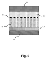
- FIG. 2 is a battery cross section illustrating an anodization process according to an embodiment of the present invention.
- FIG. 3 is a cross sectional Scanning Electron Microscope image of a partially anodized aluminum film.
- FIG. 4 is an illustration of a continuous anodized film formation process according to an embodiment of the present invention.
- FIG. 5 is a cross section of a lithium-ion battery cell including a polymeric separator layer sandwiched between two nano-PAO separator layers, according to an embodiment of the present invention.
- FIG. 6 is an illustration of a 3D battery including both polyolefin and nano-PAO separator layers, according to an embodiment of the present invention.
- a three-dimensional energy storage device can be one in which an anode, a cathode, and/or a separator are non-laminar in nature. For example, if electrodes protrude sufficiently from a backplane structural layer to form a non-laminar active battery component, then the surface area for such a non-laminar component may be greater than twice the geometrical footprint of its backplane structural layer.
- Three-dimensional batteries may have significantly higher energy densities than two-dimensional ones, and may provide a higher rate of energy retrieval due to reduced distances for electron and ion transfer between an anode and a cathode.
- Some examples of three-dimensional battery architectures that are capable of use with certain embodiments of the present invention may include three-dimensional interdigitated arrays of lithium ion insertion electrodes in the shape of pillars, plates, concentric circles, or waves. Other configurations, such as honeycomb structures and spirals might also be used with certain embodiments of the present invention.
- Such three-dimensional architectures may have cathodes and anodes protruding from the same backplane structural layer or from different backplanes.
- FIG. 2 shows an anodization cell illustrating an anodization process for a battery separator according to an embodiment of the present invention.
- the anodization cell consists of an anode 20 placed in electrical contact with the starting metal to be oxidized 21 together with a cathode 22 .
- the anode 20 may comprise vanadium, carbon, silicon, aluminum, tin, or lithium titanate, for example.
- the metal to be anodized can either serve as the anode itself or can be deposited on top of another metallic or non-metallic substrate which acts as the base material.
- the cathode material can be any conductive material that can support a cathodic reaction such as hydrogen evolution. Typical materials used are stainless steel, or nickel.
- An acid electrolyte solution 24 (typically oxalic, sulfuric, phosphoric, citric, etc. in the case of aluminum) is added to the cell.
- An electrical potential may then be applied across the anode 20 and cathode 22 , using a conventional external power supply (not shown in FIG. 2 ), at which time electrochemical anodization of the starting metal will commence and continue.
- the first reaction that occurs during the anodization process is the formation of a non-porous barrier layer 23 at the initial acid/metal interface.
- surface pores form with approximately periodic spacing, and these surface pores become the template for pore growth/propagation in the porous anodized metal layer.
- the electrochemical anodization process may be stopped before the starting metal is completely consumed, or else run until all of the starting metal is anodized.
- FIG. 2 illustrates a situation where the starting metal has been partially anodized.
- the electrochemical anodization is continued until the porous anodized metal layer is of at least 100 nanometers thickness.
- the process step of forming the plurality of pores through the starting metal is performed concurrently with the process step of electrochemical anodization of the starting metal, so that the anodization is used as a means to form the plurality of pores.
- both the pore size and porosity may be varied independently of one another by varying process parameters such as voltage, acid concentration, temperature etc.
- the resulting pores may have diameters on the nanometer scale. Since the barrier layer is insulating, pores 25 propagate due to electron transfer through the pores 25 , and therefore propagate towards the base material in a substantially straight and parallel fashion. Since the resulting pore alignment is substantially towards the base material, the resulting porous metal oxide may be particularly suitable for use as a battery separator layer.
- FIG. 3 shows an example of a scanning electron microscopic image of a cross section of pores formed in a partially anodized aluminum film.
- the anodization depicted in FIG. 3 is partial because the starting metal has not been completely consumed. Rather, an aluminum layer 30 remains with an anodized oxide layer 31 being visible above the aluminum layer 30 .
- the pores e.g. pore 32
- the pores are aligned substantially towards the starting metal aluminum layer 30 , and have a diameter on the order of a few tens of nanometers. Having pore diameters less than 100 nanometers, such an anodized material may be referred to as being a nano-porous anodized oxide (hereinafter, a “nano-PAO”).
- the starting metal is aluminum
- the resulting material may be referred to as an anodized aluminum nano-pore material.
- an oxide powder may be used as a raw material to form a slurry with a binder, and then the slurry may be coated and dried onto a substrate. Porous metal oxide films may also be sintered in order to provide better particle-to-particle adhesion. The substrate may then be removed to form monolithic porous oxide films.
- one of ordinary skill in the art can readily distinguish the porous metal oxide film that is formed from an oxide powder, from an anodized porous oxide film, based on the resulting structure of the film alone (e.g. from the pores as viewed in cross-section with the aid of microscopy.
- the film comprising oxide powder has a thickness that cannot easily be reduced below the particle size.
- anodic oxide separators may be accomplished in several ways for various classes of batteries.
- a nano-PAO separator layer may be formed on top of an anode laminate (e.g. where the anode laminate has a graphite anode layer on top of a carbon, copper, or nickel current collector layer).
- the graphitic carbon may be compressed to form a coherent electrode.
- Such an electrode may then be coated with aluminum by using a vacuum process and/or by electroplating.
- the sandwich of anode and aluminum may then be subjected to electrochemical anodization in order to convert the aluminum into aluminum oxide (“alumina”).
- FIG. 4 is an illustration of a continuous anodized film formation process, according to an embodiment of the present invention that produces an anode-nano-PAO composite layer.
- acid electrolyte 40 comes into contact with a metal roll 41 .
- the metal roll 41 is electrically and mechanically connected to the anode 42 , and serves as a current supply pole for the anode 42 .
- the anode 42 is a laminate including a battery anode current collector layer (which is adjacent and contacts the metal roll 41 ), the battery anode material layer, and a starting metal layer, with the battery anode material layer being disposed between the battery anode current collector layer and the starting metal layer.
- the anodization reaction is initiated by the application of an electrical potential between the metal role 41 and the anodization cathode 44 .
- the starting metal in the layered stack partially or fully anodized (to form a porous anodized oxide) as the anode 42 is fed across the metal roll 41 .
- the porous anodized oxide may comprise alumina, titanium oxide, zirconium oxide, silicon oxide, niobium oxide, tungsten oxide, tantalum oxide, or hafnium oxide.
- the starting metal is aluminum, during anodization an alumina barrier layer is first formed on the aluminum, and then pores may be formed through the barrier layer. In certain embodiments, both the pore size and porosity may be controlled independently during anodization.
- the output from this process is a sheet including a battery anode current collector, a battery anode, and anodized alumina separator.
- This anode-separator composite sheet may be useful in subsequent battery assembly, with or without an additional polymeric separator.
- a similar process may be used to incorporate the separator on top of a coated cathode material provided the cathode material is stable in aqueous acidic systems.
- a nano-PAO layer is used as a stand-alone separator in a battery.
- a film of aluminum may be partially anodized and then released as a standalone film by etching away the remainder of the starting metal.
- a film of starting metal may be deposited on a base layer, and then the film of starting metal may be fully anodized and then released as a standalone film by etching away the base layer.
- a nano-PAO separator may be produced on an existing polymeric separator, for example a separator layer including an organic material such as polypropylene, polyethylene, polyamide, polytetraflouroethylene, polyvinylidine fluoride, polyvinylchloride, polyimide, polycarbonate, or cellulose.
- a separator layer including an organic material such as polypropylene, polyethylene, polyamide, polytetraflouroethylene, polyvinylidine fluoride, polyvinylchloride, polyimide, polycarbonate, or cellulose.
- the polymeric separator layer has a plurality of through-pores that extend all the way through its thickness.
- each of the plurality of through-pores preferably defines a through-pore diameter that is less than 100 nm.
- a first metal layer (e.g. including aluminum) may be deposited on a first side of the porous polymeric separator layer.
- a starting metal sub-layer of the first metal layer may first be deposited on the polymeric separator layer, for example by a vacuum deposition process, and then a thicker metal sub-layer may be deposited on the starting metal layer.
- Such a separator material combination may then be anodized using the process described above in order to obtain a dual-layer or multi-layered separator, with the nano-PAO layer then residing above or on the polymeric separator.
- electrochemical anodization of the starting metal layer is continued until a least 100 nm of its thickness has been anodized.
- electrochemical anodization of the starting metal layer may be continued until its full thickness (e.g. 0.25 micron to 1 mm) has been anodized.
- the nano-PAO may be added onto the polymeric separator on one or both sides.
- a layer of one-sided nano-PAO polymer composite may be sandwiched with another polymeric separator, which would result in a tri-layer polymer-nano-PAO-polymer composite separator. This process may be practically integrated into existing two dimensional battery cell manufacturing lines.
- FIG. 5 depicts a cross section of a lithium-ion battery cell 50 including a polymeric separator layer 53 sandwiched between two nano-PAO separator layers 56 , according to an embodiment of the present invention.
- the lithium-ion battery cell 50 includes a cathode current collector 51 and cathode 52 beneath a trilayer separator comprising a nano-PAO 56 layer each side of a polyolefin separator layer 53 .
- the anode 54 with the anode current collector 55 is assembled on top of the cathode & separator sandwich.
- a three-dimensional battery architecture may be fabricated by depositing a conductive material on to an inactive backbone structure, for example in the shape of a plurality of fins, and then using electrophoretic deposition to deposit electrode material on to the conductive material to create a plurality of anodes and/or cathodes.
- the backbone structure may be optionally removed as part of or at the conclusion of the fabrication process, for example by etching.
- a structural layer may be provided and then a plurality of protrusions can be formed that protrude from the structural layer.
- Each of the protrusions may include or may be provided with an electrically conductive surface, and an electrode layer may be deposited on the plurality of protrusions.
- conventional roll-to-roll manufactured polyolefin separators cannot be easily integrated.
- a thinner separator may provide a much greater opportunity to increase energy and power density.
- FIG. 6 is an illustration of a three-dimensional battery cell 60 including both polyolefin separator layers 67 and nano-PAO separator layers 66 , according to an embodiment of the present invention.
- the battery cell 60 has cathode layers 64 and anode layers 65 that protrude from a common backplane structural layer 61 by at least 50 microns.
- a cathode current collector 62 and an anode current collector 63 are each formed to protrude from the common backplane structural layer 61 .
- the current collectors 62 and 63 may themselves protrude from the backplane structural layer 61 , or else the current collectors 62 and 63 may be layers that are deposited on an inactive backbone structure that protrudes from the backplane structural layer 61 (i.e. where the underlying backbone structure gives the current collector layers their protruding shape).
- a cathode layer 64 is formed on the cathode current collector 62
- an anode layer 65 is formed on the anode current collector 63 .
- a layer of separator starting metal is then deposited on top of the anode layer 65 (e.g.
- a polyolefin composite 677 may be deposited on top of the nan-PAO separator layer, to form a bi-layer separator.
- Certain embodiments of the present invention that include one or more nano-PAO layers may provide varied, a typical, and synergistic beneficial results in battery separator applications. For example, pore diameters less than 100 nanometers may provide additional protection from transport of particulate contamination between the electrodes that could potentially cause battery shorts. Furthermore, the low tortuosity obtained in these separators may also decrease the ionic resistance of the electrolyte. For example, ions may be able to move through the separator a less tortuous path between the electrodes, which may result in lower resistance and better cell performance. Moreover, the mechanical toughness and/or thermal or mechanical stability of the separator may be improved, even at a reduced thickness relative to the prior art.
- the nano-PAO layer may also provide protection against dendrite formation during overcharge since the pore sizes may be much smaller than the size of the dendrites that occur in these batteries.
- the application of the structures and methods disclosed herein may provide varied, atypical, and synergistic beneficial results in battery separator applications.
- a sheet of starting metal that already has a pre-existing through-pores is partially or completely anodized. Ionic transport would take place in the pre-existing gaps or through-pores between the mesh members, while the nano-pores that are formed in the anodized aluminum may be subsequently closed or sealed (e.g. using boiling water).
- the starting metal sheet may take the form of a fibrous aluminum mat, porous foil, expanded mesh, or a grid, which is then anodized using the above-specified procedure to form a battery separator.
- the full thickness of the starting metal sheet may be in the range 10 to 1000 microns, and is preferably in the range 20 to 100 microns.
- the anodization may be continued until all of the starting metal sheet has been anodized, or else the anodization may be partial so that a starting metal core is left inside the fibers, mesh members, or grid members.
- the exterior of each mesh member will be coated with insulative (but relatively brittle) anodized alumina, while the interior of each mesh member will include an aluminum metal core (which is more flexible and malleable).
- the pre-existing through-pores preferably have a diameter greater than 10 nm (e.g.
- the resulting structure may be used either by itself or in conjunction with a polyolefin material as a separator in a battery.
- the pores must be through-pores that include electrolyte.
- the anode is coated with an unbroken nano-PAO layer that serves as the separator, then the nano-pores in the nano-PAO layer must extend to the anode (or at least an electrically conductive extension of the anode) so that ionic transport is enabled by the electrolyte in the nano-pores.
- the anodized layer covers a metal mesh material having through-gaps or through-pores having larger diameters than do the nano-pores
- the ionic transport may be facilitated by electrolyte in the larger diameter through-gaps or through-pores, so that the nano-pores may preferably be closed and/or blind pores rather than being through-pores.
Abstract
Description
Claims (6)
Priority Applications (1)
| Application Number | Priority Date | Filing Date | Title |
|---|---|---|---|
| US13/490,136 US8900331B2 (en) | 2007-01-12 | 2012-06-06 | Process for manufacturing a battery incorporating an anodized metallic battery separator having through-pores |
Applications Claiming Priority (4)
| Application Number | Priority Date | Filing Date | Title |
|---|---|---|---|
| US88482807P | 2007-01-12 | 2007-01-12 | |
| US12/013,398 US8663730B1 (en) | 2007-01-12 | 2008-01-11 | Method to fabricate a three dimensional battery with a porous dielectric separator |
| US12/339,400 US8216712B1 (en) | 2008-01-11 | 2008-12-19 | Anodized metallic battery separator having through-pores |
| US13/490,136 US8900331B2 (en) | 2007-01-12 | 2012-06-06 | Process for manufacturing a battery incorporating an anodized metallic battery separator having through-pores |
Related Parent Applications (1)
| Application Number | Title | Priority Date | Filing Date |
|---|---|---|---|
| US12/339,400 Division US8216712B1 (en) | 2007-01-12 | 2008-12-19 | Anodized metallic battery separator having through-pores |
Publications (2)
| Publication Number | Publication Date |
|---|---|
| US20130019468A1 US20130019468A1 (en) | 2013-01-24 |
| US8900331B2 true US8900331B2 (en) | 2014-12-02 |
Family
ID=46395876
Family Applications (2)
| Application Number | Title | Priority Date | Filing Date |
|---|---|---|---|
| US12/339,400 Active 2029-11-11 US8216712B1 (en) | 2007-01-12 | 2008-12-19 | Anodized metallic battery separator having through-pores |
| US13/490,136 Active US8900331B2 (en) | 2007-01-12 | 2012-06-06 | Process for manufacturing a battery incorporating an anodized metallic battery separator having through-pores |
Family Applications Before (1)
| Application Number | Title | Priority Date | Filing Date |
|---|---|---|---|
| US12/339,400 Active 2029-11-11 US8216712B1 (en) | 2007-01-12 | 2008-12-19 | Anodized metallic battery separator having through-pores |
Country Status (1)
| Country | Link |
|---|---|
| US (2) | US8216712B1 (en) |
Cited By (2)
| Publication number | Priority date | Publication date | Assignee | Title |
|---|---|---|---|---|
| US10170764B2 (en) | 2010-06-30 | 2019-01-01 | Semiconductor Energy Laboratory Co., Ltd. | Method for manufacturing ultra small particle, positive electrode active material of second battery using the method for manufacturing ultra small particle and method for manufacturing the same, and secondary battery using the positive electrode active material and method for manufacturing the same |
| US20220006095A1 (en) * | 2020-07-06 | 2022-01-06 | Toyota Jidosha Kabushiki Kaisha | Battery and method of producing the same |
Families Citing this family (25)
| Publication number | Priority date | Publication date | Assignee | Title |
|---|---|---|---|---|
| JP2010215930A (en) * | 2009-03-13 | 2010-09-30 | Tokyo Metropolitan Univ | Method of producing porous gold film and porous gold film |
| US8852359B2 (en) * | 2011-05-23 | 2014-10-07 | GM Global Technology Operations LLC | Method of bonding a metal to a substrate |
| US9379368B2 (en) | 2011-07-11 | 2016-06-28 | California Institute Of Technology | Electrochemical systems with electronically conductive layers |
| US10158110B2 (en) | 2011-07-11 | 2018-12-18 | California Institute Of Technology | Separators for electrochemical systems |
| JP6226879B2 (en) * | 2012-11-27 | 2017-11-08 | 日本ゴア株式会社 | Secondary battery and separator used therefor |
| US9076594B2 (en) * | 2013-03-12 | 2015-07-07 | Invensas Corporation | Capacitors using porous alumina structures |
| EP3017494B1 (en) * | 2013-07-03 | 2019-01-09 | California Institute of Technology | Carbon nanotubes - graphene hybrid structures for separator free silicon - sulfur batteries |
| US20160372729A1 (en) * | 2013-07-03 | 2016-12-22 | Cornell University | Laminated Composite Separator, Method and Application |
| CN105074989B (en) * | 2013-10-31 | 2018-11-09 | 株式会社Lg 化学 | The manufacturing method of electrode-membrane compound, the electrode-membrane compound manufactured by the manufacturing method and comprising its lithium secondary battery |
| US10714724B2 (en) | 2013-11-18 | 2020-07-14 | California Institute Of Technology | Membranes for electrochemical cells |
| US20150171398A1 (en) | 2013-11-18 | 2015-06-18 | California Institute Of Technology | Electrochemical separators with inserted conductive layers |
| CN106463692B (en) * | 2014-02-21 | 2019-09-10 | 荷兰应用自然科学研究组织Tno | Manufacture the device and method of high aspect ratio structure |
| US20150364739A1 (en) * | 2014-06-13 | 2015-12-17 | The Regents Of The University Of California | Flexible porous aluminum oxide films |
| WO2015195595A1 (en) | 2014-06-17 | 2015-12-23 | Medtronic, Inc. | Semi-solid electrolytes for batteries |
| US10333173B2 (en) | 2014-11-14 | 2019-06-25 | Medtronic, Inc. | Composite separator and electrolyte for solid state batteries |
| US10122002B2 (en) * | 2015-01-21 | 2018-11-06 | GM Global Technology Operations LLC | Thin and flexible solid electrolyte for lithium-ion batteries |
| US20160240831A1 (en) * | 2015-02-12 | 2016-08-18 | Apple Inc. | Dendrite-resistant battery |
| US10403902B2 (en) | 2015-05-15 | 2019-09-03 | Composite Materials Technology, Inc. | High capacity rechargeable batteries |
| CN108140784A (en) * | 2015-07-22 | 2018-06-08 | 赛尔格有限责任公司 | Improved film, partition board, battery and method |
| US10340528B2 (en) | 2015-12-02 | 2019-07-02 | California Institute Of Technology | Three-dimensional ion transport networks and current collectors for electrochemical cells |
| US10587005B2 (en) | 2016-03-30 | 2020-03-10 | Wildcat Discovery Technologies, Inc. | Solid electrolyte compositions |
| EP3507242B1 (en) | 2016-09-01 | 2021-07-14 | COMPOSITE MATERIALS TECHNOLOGY, Inc. | Nano-scale/nanostructured si coating on valve metal substrate for lib anodes |
| HUE046592T2 (en) * | 2016-11-29 | 2020-03-30 | Bosch Gmbh Robert | Separator for a lithium-ion cell and lithium-ion cell comprising such a separator |
| US11658304B2 (en) * | 2020-02-27 | 2023-05-23 | GM Global Technology Operations LLC | Composite reference electrode substrate and methods relating thereto |
| CN111613447B (en) * | 2020-05-22 | 2022-03-04 | 东莞东阳光科研发有限公司 | Laminated electrolytic capacitor and method for manufacturing the same |
Citations (28)
| Publication number | Priority date | Publication date | Assignee | Title |
|---|---|---|---|---|
| US4113579A (en) | 1977-04-28 | 1978-09-12 | Sprague Electric Company | Process for producing an aluminum electrolytic capacitor having a stable oxide film |
| US4820599A (en) | 1987-05-18 | 1989-04-11 | Sanyo Electric Co., Ltd. | Non-aqueous electrolyte type secondary cell |
| US4996129A (en) | 1988-01-05 | 1991-02-26 | Alcan International Limited | Battery |
| US5294504A (en) | 1988-08-30 | 1994-03-15 | Osaka Gas Company, Ltd. | Three-dimensional microstructure as a substrate for a battery electrode |
| US5993990A (en) | 1998-05-15 | 1999-11-30 | Moltech Corporation | PTC current limiting header assembly |
| CA2388711A1 (en) | 1999-10-22 | 2001-05-03 | Sanyo Electric Co., Ltd. | Electrode for use in lithium battery and rechargeable lithium battery |
| US20020034685A1 (en) | 2000-09-01 | 2002-03-21 | Takaya Sato | Lithium based battery |
| US6432586B1 (en) * | 2000-04-10 | 2002-08-13 | Celgard Inc. | Separator for a high energy rechargeable lithium battery |
| US6432585B1 (en) | 1997-01-28 | 2002-08-13 | Canon Kabushiki Kaisha | Electrode structural body, rechargeable battery provided with said electrode structural body, and rechargeable battery |
| US6498406B1 (en) | 1999-01-29 | 2002-12-24 | Sanyo Electric Co., Ltd. | Power source containing rechargeable batteries |
| US20040092395A1 (en) | 2002-08-05 | 2004-05-13 | Denso Corporation | Ceramic catalyst body |
| US20040214079A1 (en) | 2003-04-22 | 2004-10-28 | Simburger Edward J. | Integrated thin film battery and circuit module |
| US6878173B2 (en) | 2000-08-30 | 2005-04-12 | Matsushita Electric Industrial Co., Ltd. | Method for manufacturing electrode plate for cell |
| US7056455B2 (en) | 2001-04-06 | 2006-06-06 | Carnegie Mellon University | Process for the preparation of nanostructured materials |
| US20060121342A1 (en) | 2004-11-17 | 2006-06-08 | Hitachi, Ltd. | Secondary battery and production method thereof |
| US20060188784A1 (en) | 2003-07-28 | 2006-08-24 | Akinori Sudoh | High density electrode and battery using the electrode |
| US20060269845A1 (en) | 2005-05-26 | 2006-11-30 | Ferro Corporation | Nonaqueous electrolytic solution for electrochemical cells |
| US20060281007A1 (en) | 2004-05-25 | 2006-12-14 | Shuji Tsutsumi | Lithium ion secondary battery and method for manufacturing same |
| US7153609B2 (en) | 2001-09-05 | 2006-12-26 | Kabushiki Kaisha Toshiba | Rechargeable battery with nonaqueous electrolyte |
| US20070172732A1 (en) | 2006-01-20 | 2007-07-26 | In-Sun Jung | Anode active material, method of preparing the same, and anode and lithium battery containing the anode active material |
| US20070243460A1 (en) | 2006-04-12 | 2007-10-18 | Steven Allen Carlson | Safety shutdown separators |
| WO2008072638A1 (en) | 2006-12-15 | 2008-06-19 | Tokyo Ohka Kogyo Co., Ltd. | Negative electrode base member |
| JP2008153035A (en) | 2006-12-15 | 2008-07-03 | Tokyo Ohka Kogyo Co Ltd | Anode base material |
| JP2008153036A (en) | 2006-12-15 | 2008-07-03 | Tokyo Ohka Kogyo Co Ltd | Anode base material |
| JP2008153034A (en) | 2006-12-15 | 2008-07-03 | Tokyo Ohka Kogyo Co Ltd | Anode base material |
| JP2008153033A (en) | 2006-12-15 | 2008-07-03 | Tokyo Ohka Kogyo Co Ltd | Anode base material |
| US20090035664A1 (en) | 2007-05-25 | 2009-02-05 | Massachusetts Institute Of Technology | Batteries and electrodes for use thereof |
| US20110045168A1 (en) * | 2005-11-28 | 2011-02-24 | Lg Chem, Ltd. | Organic/inorganic composite porous membrane and electrochemical device using the same |
-
2008
- 2008-12-19 US US12/339,400 patent/US8216712B1/en active Active
-
2012
- 2012-06-06 US US13/490,136 patent/US8900331B2/en active Active
Patent Citations (29)
| Publication number | Priority date | Publication date | Assignee | Title |
|---|---|---|---|---|
| US4113579A (en) | 1977-04-28 | 1978-09-12 | Sprague Electric Company | Process for producing an aluminum electrolytic capacitor having a stable oxide film |
| US4820599A (en) | 1987-05-18 | 1989-04-11 | Sanyo Electric Co., Ltd. | Non-aqueous electrolyte type secondary cell |
| US4996129A (en) | 1988-01-05 | 1991-02-26 | Alcan International Limited | Battery |
| US5294504A (en) | 1988-08-30 | 1994-03-15 | Osaka Gas Company, Ltd. | Three-dimensional microstructure as a substrate for a battery electrode |
| US6432585B1 (en) | 1997-01-28 | 2002-08-13 | Canon Kabushiki Kaisha | Electrode structural body, rechargeable battery provided with said electrode structural body, and rechargeable battery |
| US5993990A (en) | 1998-05-15 | 1999-11-30 | Moltech Corporation | PTC current limiting header assembly |
| US6498406B1 (en) | 1999-01-29 | 2002-12-24 | Sanyo Electric Co., Ltd. | Power source containing rechargeable batteries |
| CA2388711A1 (en) | 1999-10-22 | 2001-05-03 | Sanyo Electric Co., Ltd. | Electrode for use in lithium battery and rechargeable lithium battery |
| US6432586B1 (en) * | 2000-04-10 | 2002-08-13 | Celgard Inc. | Separator for a high energy rechargeable lithium battery |
| US6878173B2 (en) | 2000-08-30 | 2005-04-12 | Matsushita Electric Industrial Co., Ltd. | Method for manufacturing electrode plate for cell |
| US20020034685A1 (en) | 2000-09-01 | 2002-03-21 | Takaya Sato | Lithium based battery |
| US7056455B2 (en) | 2001-04-06 | 2006-06-06 | Carnegie Mellon University | Process for the preparation of nanostructured materials |
| US7153609B2 (en) | 2001-09-05 | 2006-12-26 | Kabushiki Kaisha Toshiba | Rechargeable battery with nonaqueous electrolyte |
| US20040092395A1 (en) | 2002-08-05 | 2004-05-13 | Denso Corporation | Ceramic catalyst body |
| US20040214079A1 (en) | 2003-04-22 | 2004-10-28 | Simburger Edward J. | Integrated thin film battery and circuit module |
| US20060188784A1 (en) | 2003-07-28 | 2006-08-24 | Akinori Sudoh | High density electrode and battery using the electrode |
| US20060281007A1 (en) | 2004-05-25 | 2006-12-14 | Shuji Tsutsumi | Lithium ion secondary battery and method for manufacturing same |
| US20060121342A1 (en) | 2004-11-17 | 2006-06-08 | Hitachi, Ltd. | Secondary battery and production method thereof |
| US20060269845A1 (en) | 2005-05-26 | 2006-11-30 | Ferro Corporation | Nonaqueous electrolytic solution for electrochemical cells |
| US20110045168A1 (en) * | 2005-11-28 | 2011-02-24 | Lg Chem, Ltd. | Organic/inorganic composite porous membrane and electrochemical device using the same |
| US20070172732A1 (en) | 2006-01-20 | 2007-07-26 | In-Sun Jung | Anode active material, method of preparing the same, and anode and lithium battery containing the anode active material |
| US20070243460A1 (en) | 2006-04-12 | 2007-10-18 | Steven Allen Carlson | Safety shutdown separators |
| WO2008072638A1 (en) | 2006-12-15 | 2008-06-19 | Tokyo Ohka Kogyo Co., Ltd. | Negative electrode base member |
| JP2008153035A (en) | 2006-12-15 | 2008-07-03 | Tokyo Ohka Kogyo Co Ltd | Anode base material |
| JP2008153036A (en) | 2006-12-15 | 2008-07-03 | Tokyo Ohka Kogyo Co Ltd | Anode base material |
| JP2008153034A (en) | 2006-12-15 | 2008-07-03 | Tokyo Ohka Kogyo Co Ltd | Anode base material |
| JP2008153033A (en) | 2006-12-15 | 2008-07-03 | Tokyo Ohka Kogyo Co Ltd | Anode base material |
| US20100119939A1 (en) | 2006-12-15 | 2010-05-13 | Tokyo Ohka Kogyo Co., Ltd. | Negative electrode base member |
| US20090035664A1 (en) | 2007-05-25 | 2009-02-05 | Massachusetts Institute Of Technology | Batteries and electrodes for use thereof |
Non-Patent Citations (6)
| Title |
|---|
| Arora, P. and Zhang, Z., "Battery Separators", Chem. Reviews, 2004, 104, 4419-4462. |
| Lehmann, The Physics of Macropore Formation in Low Doped n-Type Silicon, J. Electrochem. Soc. 140 (1993),10, 2836-2843. |
| Long et al., "Three Dimensional Battery Architectures" Chemical Reviews, 2004, 104, 4463-4492. |
| Masuda, et al., Ordered Metal Nanohole Arrays Made by a Two-Step Replication of Honeycomb Structures of Anodic Alumina, Science, New Series, vol. 268, No. 5216 (Jun. 9, 1995), pp. 1466-1468, USA. |
| Nishizawa et al., "Template synthesis of Polypyrrole coated Spinel LiMn2O4 Nanotubules and their properties as Cathode Active Materials for Lithium Batteries" Journal of the Electrochemical Society, 1923-1927, 1997. |
| Shin et al. Porous Silicon Negative Electrodes for Rachargeable Lithium Batteries, Journal of Power Sources, 139 (2005) 314-320. |
Cited By (2)
| Publication number | Priority date | Publication date | Assignee | Title |
|---|---|---|---|---|
| US10170764B2 (en) | 2010-06-30 | 2019-01-01 | Semiconductor Energy Laboratory Co., Ltd. | Method for manufacturing ultra small particle, positive electrode active material of second battery using the method for manufacturing ultra small particle and method for manufacturing the same, and secondary battery using the positive electrode active material and method for manufacturing the same |
| US20220006095A1 (en) * | 2020-07-06 | 2022-01-06 | Toyota Jidosha Kabushiki Kaisha | Battery and method of producing the same |
Also Published As
| Publication number | Publication date |
|---|---|
| US20130019468A1 (en) | 2013-01-24 |
| US8216712B1 (en) | 2012-07-10 |
Similar Documents
| Publication | Publication Date | Title |
|---|---|---|
| US8900331B2 (en) | Process for manufacturing a battery incorporating an anodized metallic battery separator having through-pores | |
| JP6949379B2 (en) | Batteries that utilize an anode that is directly coated on a nanoporous separator | |
| US11901500B2 (en) | Sandwich electrodes | |
| US10256500B2 (en) | Three-dimensional batteries and methods of manufacturing the same | |
| JP6367390B2 (en) | Production of large capacity prism lithium ion alloy anode | |
| US8486562B2 (en) | Thin film electrochemical energy storage device with three-dimensional anodic structure | |
| EP2387805B1 (en) | A process for producing carbon nanostructure on a flexible substrate, and energy storage devices comprising flexible carbon nanostructure electrodes | |
| US10381651B2 (en) | Device and method of manufacturing high-aspect ratio structures | |
| US20130003261A1 (en) | Lithium plate, method for lithiation of electrode and energy storage device | |
| KR102545769B1 (en) | Lithium battery manufacturing method | |
| US20170263939A1 (en) | Electrode material and energy storage apparatus | |
| KR20080080134A (en) | Lithium metal foil for battery or capacitor | |
| JP2019519079A (en) | Method of manufacturing lithium battery | |
| CN104253266A (en) | Multilayer film silicon/graphene composite material anode structure | |
| US8663730B1 (en) | Method to fabricate a three dimensional battery with a porous dielectric separator | |
| US8379368B2 (en) | Method for manufacturing lithium ion capacitor and lithium ion capacitor manufactured using the same | |
| US20160226061A1 (en) | Batteries using vertically free-standing graphene, carbon nanosheets, and/or three dimensional carbon nanostructures as electrodes | |
| Lee et al. | Facile Fabrication of High‐Performance Hybrid Supercapacitor by One-Step, Self‐Grown Copper Nanopillar Forest Anchored with Fe 3 O 4 Anode | |
| CN114008814A (en) | Composite lithium metal anode for increased energy density and reduced charge time | |
| Johnson et al. | Three-dimensional lithium-ion batteries with interdigitated electrodes | |
| KR101550367B1 (en) | Electrode structure having conducting linear structure method for fabricating the electrode structure and lithium secondary battery | |
| Synodis et al. | MEMS enabled scalable fabrication of high performance lithium ion battery electrodes | |
| Kim et al. | Micropillar‐based channel patterning in high‐loading graphite anodes for superior Li‐ion batteries | |
| CN115954483A (en) | Composite current collector, electrode plate and lithium ion battery | |
| CN116706218A (en) | Method for manufacturing a combination of an electrode and a solid electrolyte for a battery cell |
Legal Events
| Date | Code | Title | Description |
|---|---|---|---|
| STCF | Information on status: patent grant |
Free format text: PATENTED CASE |
|
| MAFP | Maintenance fee payment |
Free format text: PAYMENT OF MAINTENANCE FEE, 4TH YR, SMALL ENTITY (ORIGINAL EVENT CODE: M2551) Year of fee payment: 4 |
|
| AS | Assignment |
Owner name: THE OBERST FAMILY TRUST, DATED 12/7/2005, CALIFORNIA Free format text: SECURED OPTION AGREEMENT;ASSIGNOR:ENOVIX CORPORATION;REEL/FRAME:047348/0007 Effective date: 20180731 Owner name: EDDY ZERVIGON REVOCABLE TRUST U/A DATED FEBRUARY 16, 2010 -EDDY ZERVIGON AS TRUSTEE, NEW JERSEY Free format text: SECURED OPTION AGREEMENT;ASSIGNOR:ENOVIX CORPORATION;REEL/FRAME:047348/0007 Effective date: 20180731 Owner name: RODGERS MASSEY REVOCABLE LIVING TRUST DTD 4/4/11, THURMAN JOHN RODGERS, TRUSTEE, CALIFORNIA Free format text: SECURED OPTION AGREEMENT;ASSIGNOR:ENOVIX CORPORATION;REEL/FRAME:047348/0007 Effective date: 20180731 Owner name: DPIP PROJECT LION SERIES, NORTH CAROLINA Free format text: SECURED OPTION AGREEMENT;ASSIGNOR:ENOVIX CORPORATION;REEL/FRAME:047348/0007 Effective date: 20180731 Owner name: PETRICK, MICHAEL, CONNECTICUT Free format text: SECURED OPTION AGREEMENT;ASSIGNOR:ENOVIX CORPORATION;REEL/FRAME:047348/0007 Effective date: 20180731 Owner name: YORK DISTRESSED ASSET FUND III, L.P., NEW YORK Free format text: SECURED OPTION AGREEMENT;ASSIGNOR:ENOVIX CORPORATION;REEL/FRAME:047348/0007 Effective date: 20180731 Owner name: SABOUNGHI, EDGAR, NEW YORK Free format text: SECURED OPTION AGREEMENT;ASSIGNOR:ENOVIX CORPORATION;REEL/FRAME:047348/0007 Effective date: 20180731 Owner name: RODGERS MASSEY REVOCABLE LIVING TRUST DTD 4/4/11, Free format text: SECURED OPTION AGREEMENT;ASSIGNOR:ENOVIX CORPORATION;REEL/FRAME:047348/0007 Effective date: 20180731 Owner name: GCH INVESTMENTS, LLC, CALIFORNIA Free format text: SECURED OPTION AGREEMENT;ASSIGNOR:ENOVIX CORPORATION;REEL/FRAME:047348/0007 Effective date: 20180731 Owner name: JEROME INVESTMENTS, LLC, NEW JERSEY Free format text: SECURED OPTION AGREEMENT;ASSIGNOR:ENOVIX CORPORATION;REEL/FRAME:047348/0007 Effective date: 20180731 Owner name: EDDY ZERVIGON REVOCABLE TRUST U/A DATED FEBRUARY 1 Free format text: SECURED OPTION AGREEMENT;ASSIGNOR:ENOVIX CORPORATION;REEL/FRAME:047348/0007 Effective date: 20180731 Owner name: GREENBERGER, MARC, NEW JERSEY Free format text: SECURED OPTION AGREEMENT;ASSIGNOR:ENOVIX CORPORATION;REEL/FRAME:047348/0007 Effective date: 20180731 Owner name: SHERMAN, JOEL, DR., NEW JERSEY Free format text: SECURED OPTION AGREEMENT;ASSIGNOR:ENOVIX CORPORATION;REEL/FRAME:047348/0007 Effective date: 20180731 Owner name: MCGOVERN, BRIAN, NEW JERSEY Free format text: SECURED OPTION AGREEMENT;ASSIGNOR:ENOVIX CORPORATION;REEL/FRAME:047348/0007 Effective date: 20180731 Owner name: THE OBERST FAMILY TRUST, DATED 12/7/2005, CALIFORN Free format text: SECURED OPTION AGREEMENT;ASSIGNOR:ENOVIX CORPORATION;REEL/FRAME:047348/0007 Effective date: 20180731 |
|
| AS | Assignment |
Owner name: RODGERS MASSEY REVOCABLE LIVING TRUST DTD 4/4/11, THURMAN JOHN RODGERS, TRUSTEE, CALIFORNIA Free format text: FIRST AMENDMENT TO SECURED OPTION AGREEMENT;ASSIGNOR:ENOVIX CORPORATION;REEL/FRAME:047733/0685 Effective date: 20180731 Owner name: THE OBERST FAMILY TRUST, DATED 12/7/2005, CALIFORNIA Free format text: FIRST AMENDMENT TO SECURED OPTION AGREEMENT;ASSIGNOR:ENOVIX CORPORATION;REEL/FRAME:047733/0685 Effective date: 20180731 Owner name: EDDY ZERVIGON REVOCABLE TRUST U/A DATED FEBRUARY 16, 2010 -EDDY ZERVIGON AS TRUSTEE, NEW JERSEY Free format text: FIRST AMENDMENT TO SECURED OPTION AGREEMENT;ASSIGNOR:ENOVIX CORPORATION;REEL/FRAME:047733/0685 Effective date: 20180731 Owner name: SABOUNGHI, EDGAR, NEW YORK Free format text: FIRST AMENDMENT TO SECURED OPTION AGREEMENT;ASSIGNOR:ENOVIX CORPORATION;REEL/FRAME:047733/0685 Effective date: 20180731 Owner name: DPIP PROJECT LION SERIES, NORTH CAROLINA Free format text: FIRST AMENDMENT TO SECURED OPTION AGREEMENT;ASSIGNOR:ENOVIX CORPORATION;REEL/FRAME:047733/0685 Effective date: 20180731 Owner name: EDDY ZERVIGON REVOCABLE TRUST U/A DATED FEBRUARY 1 Free format text: FIRST AMENDMENT TO SECURED OPTION AGREEMENT;ASSIGNOR:ENOVIX CORPORATION;REEL/FRAME:047733/0685 Effective date: 20180731 Owner name: MCGOVERN, BRIAN, NEW JERSEY Free format text: FIRST AMENDMENT TO SECURED OPTION AGREEMENT;ASSIGNOR:ENOVIX CORPORATION;REEL/FRAME:047733/0685 Effective date: 20180731 Owner name: JEROME INVESTMENTS, LLC, NEW JERSEY Free format text: FIRST AMENDMENT TO SECURED OPTION AGREEMENT;ASSIGNOR:ENOVIX CORPORATION;REEL/FRAME:047733/0685 Effective date: 20180731 Owner name: RODGERS MASSEY REVOCABLE LIVING TRUST DTD 4/4/11, Free format text: FIRST AMENDMENT TO SECURED OPTION AGREEMENT;ASSIGNOR:ENOVIX CORPORATION;REEL/FRAME:047733/0685 Effective date: 20180731 Owner name: GCH INVESTMENTS, LLC, CALIFORNIA Free format text: FIRST AMENDMENT TO SECURED OPTION AGREEMENT;ASSIGNOR:ENOVIX CORPORATION;REEL/FRAME:047733/0685 Effective date: 20180731 Owner name: SHERMAN, JOEL, DR., NEW JERSEY Free format text: FIRST AMENDMENT TO SECURED OPTION AGREEMENT;ASSIGNOR:ENOVIX CORPORATION;REEL/FRAME:047733/0685 Effective date: 20180731 Owner name: YORK DISTRESSED ASSET FUND III, L.P., NEW YORK Free format text: FIRST AMENDMENT TO SECURED OPTION AGREEMENT;ASSIGNOR:ENOVIX CORPORATION;REEL/FRAME:047733/0685 Effective date: 20180731 Owner name: THE OBERST FAMILY TRUST, DATED 12/7/2005, CALIFORN Free format text: FIRST AMENDMENT TO SECURED OPTION AGREEMENT;ASSIGNOR:ENOVIX CORPORATION;REEL/FRAME:047733/0685 Effective date: 20180731 Owner name: TUNE HOUSE CAPITAL I LLC, CALIFORNIA Free format text: FIRST AMENDMENT TO SECURED OPTION AGREEMENT;ASSIGNOR:ENOVIX CORPORATION;REEL/FRAME:047733/0685 Effective date: 20180731 Owner name: PETRICK, MICHAEL, CONNECTICUT Free format text: FIRST AMENDMENT TO SECURED OPTION AGREEMENT;ASSIGNOR:ENOVIX CORPORATION;REEL/FRAME:047733/0685 Effective date: 20180731 Owner name: GREENBERGER, MARC, NEW JERSEY Free format text: FIRST AMENDMENT TO SECURED OPTION AGREEMENT;ASSIGNOR:ENOVIX CORPORATION;REEL/FRAME:047733/0685 Effective date: 20180731 |
|
| AS | Assignment |
Owner name: BRIAN MCGOVERN, NEW JERSEY Free format text: SECOND AMENDMENT TO SECURED OPTION AGREEMENT;ASSIGNOR:ENOVIX CORPORATION;REEL/FRAME:048432/0300 Effective date: 20181221 Owner name: MICHAEL PETRICK, CONNECTICUT Free format text: SECOND AMENDMENT TO SECURED OPTION AGREEMENT;ASSIGNOR:ENOVIX CORPORATION;REEL/FRAME:048432/0300 Effective date: 20181221 Owner name: GCH INVESTMENTS, LLC, CALIFORNIA Free format text: SECOND AMENDMENT TO SECURED OPTION AGREEMENT;ASSIGNOR:ENOVIX CORPORATION;REEL/FRAME:048432/0300 Effective date: 20181221 Owner name: EDGAR SABOUNGHI, NEW YORK Free format text: SECOND AMENDMENT TO SECURED OPTION AGREEMENT;ASSIGNOR:ENOVIX CORPORATION;REEL/FRAME:048432/0300 Effective date: 20181221 Owner name: TUNE HOUSE CAPITAL I LLC, CALIFORNIA Free format text: SECOND AMENDMENT TO SECURED OPTION AGREEMENT;ASSIGNOR:ENOVIX CORPORATION;REEL/FRAME:048432/0300 Effective date: 20181221 Owner name: MARC GREENBERGER, NEW JERSEY Free format text: SECOND AMENDMENT TO SECURED OPTION AGREEMENT;ASSIGNOR:ENOVIX CORPORATION;REEL/FRAME:048432/0300 Effective date: 20181221 Owner name: DCM V, L.P., CALIFORNIA Free format text: SECOND AMENDMENT TO SECURED OPTION AGREEMENT;ASSIGNOR:ENOVIX CORPORATION;REEL/FRAME:048432/0300 Effective date: 20181221 Owner name: YORK DISTRESSED ASSET FUND III, L.P., NEW YORK Free format text: SECOND AMENDMENT TO SECURED OPTION AGREEMENT;ASSIGNOR:ENOVIX CORPORATION;REEL/FRAME:048432/0300 Effective date: 20181221 Owner name: DR. JOEL SHERMAN, NEW JERSEY Free format text: SECOND AMENDMENT TO SECURED OPTION AGREEMENT;ASSIGNOR:ENOVIX CORPORATION;REEL/FRAME:048432/0300 Effective date: 20181221 Owner name: RODGERS MASSEY REVOCABLE LIVING TRUST DTD 4/4/11, Free format text: SECOND AMENDMENT TO SECURED OPTION AGREEMENT;ASSIGNOR:ENOVIX CORPORATION;REEL/FRAME:048432/0300 Effective date: 20181221 Owner name: DPIP PROJECT LION SERIES, NORTH CAROLINA Free format text: SECOND AMENDMENT TO SECURED OPTION AGREEMENT;ASSIGNOR:ENOVIX CORPORATION;REEL/FRAME:048432/0300 Effective date: 20181221 Owner name: JEROME INVESTMENTS, LLC, NEW JERSEY Free format text: SECOND AMENDMENT TO SECURED OPTION AGREEMENT;ASSIGNOR:ENOVIX CORPORATION;REEL/FRAME:048432/0300 Effective date: 20181221 Owner name: EDDY ZERVIGON REVOCABLE TRUST U/A DATED FEBRUARY 1 Free format text: SECOND AMENDMENT TO SECURED OPTION AGREEMENT;ASSIGNOR:ENOVIX CORPORATION;REEL/FRAME:048432/0300 Effective date: 20181221 Owner name: THE OBERST FAMILY TRUST, DATED 12/7/2005, CALIFORN Free format text: SECOND AMENDMENT TO SECURED OPTION AGREEMENT;ASSIGNOR:ENOVIX CORPORATION;REEL/FRAME:048432/0300 Effective date: 20181221 Owner name: THE OBERST FAMILY TRUST, DATED 12/7/2005, CALIFORNIA Free format text: SECOND AMENDMENT TO SECURED OPTION AGREEMENT;ASSIGNOR:ENOVIX CORPORATION;REEL/FRAME:048432/0300 Effective date: 20181221 Owner name: RODGERS MASSEY REVOCABLE LIVING TRUST DTD 4/4/11, THURMAN JOHN RODGERS, TRUSTEE, CALIFORNIA Free format text: SECOND AMENDMENT TO SECURED OPTION AGREEMENT;ASSIGNOR:ENOVIX CORPORATION;REEL/FRAME:048432/0300 Effective date: 20181221 Owner name: EDDY ZERVIGON REVOCABLE TRUST U/A DATED FEBRUARY 16, 2010 - EDDY ZERVIGON AS TRUSTEE, NEW JERSEY Free format text: SECOND AMENDMENT TO SECURED OPTION AGREEMENT;ASSIGNOR:ENOVIX CORPORATION;REEL/FRAME:048432/0300 Effective date: 20181221 |
|
| AS | Assignment |
Owner name: ENOVIX CORPORATION, CALIFORNIA Free format text: TERMINATION OF SECURED OPTION AGREEMENT;ASSIGNORS:YORK DISTRESSED ESSET FUND III, L.P.;RODGERS MASSEY REVOCABLE LIVING TRUST DTD 4/4/11, THURMAN JOHN RODGERS, TRUSTEE;PETRICK, MICHAEL;AND OTHERS;REEL/FRAME:055229/0544 Effective date: 20200325 |
|
| FEPP | Fee payment procedure |
Free format text: ENTITY STATUS SET TO UNDISCOUNTED (ORIGINAL EVENT CODE: BIG.); ENTITY STATUS OF PATENT OWNER: LARGE ENTITY |
|
| AS | Assignment |
Owner name: ENOVIX OPERATIONS INC., CALIFORNIA Free format text: MERGER AND CHANGE OF NAME;ASSIGNORS:RSVAC MERGER SUB INC.;ENOVIX CORPORATION;ENOVIX OPERATIONS INC.;REEL/FRAME:058646/0894 Effective date: 20210713 |
|
| MAFP | Maintenance fee payment |
Free format text: PAYMENT OF MAINTENANCE FEE, 8TH YEAR, LARGE ENTITY (ORIGINAL EVENT CODE: M1552); ENTITY STATUS OF PATENT OWNER: LARGE ENTITY Year of fee payment: 8 |
|
| AS | Assignment |
Owner name: ENOVIX CORPORATION, CALIFORNIA Free format text: MERGER AND CHANGE OF NAME;ASSIGNORS:ENOVIX OPERATIONS INC.;ENOVIX CORPORATION;REEL/FRAME:062434/0809 Effective date: 20230117 |