US8899259B2 - Faucet mounting anchor - Google Patents

Faucet mounting anchor Download PDF

Info

Publication number
US8899259B2
US8899259B2 US13/695,322 US201113695322A US8899259B2 US 8899259 B2 US8899259 B2 US 8899259B2 US 201113695322 A US201113695322 A US 201113695322A US 8899259 B2 US8899259 B2 US 8899259B2
Authority
US
United States
Prior art keywords
anchor
mounting
adapter
tube
spout
Prior art date
Legal status (The legal status is an assumption and is not a legal conclusion. Google has not performed a legal analysis and makes no representation as to the accuracy of the status listed.)
Active, expires
Application number
US13/695,322
Other versions
US20130048100A1 (en
Inventor
Patrick B. Jonte
Michael Scot Rosko
Todd Midkiff
Michael J. Veros
Current Assignee (The listed assignees may be inaccurate. Google has not performed a legal analysis and makes no representation or warranty as to the accuracy of the list.)
Delta Faucet Co
Original Assignee
Masco Corp of Indiana
Priority date (The priority date is an assumption and is not a legal conclusion. Google has not performed a legal analysis and makes no representation as to the accuracy of the date listed.)
Filing date
Publication date
Application filed by Masco Corp of Indiana filed Critical Masco Corp of Indiana
Priority to US13/695,322 priority Critical patent/US8899259B2/en
Assigned to MASCO CORPORATION OF INDIANA reassignment MASCO CORPORATION OF INDIANA ASSIGNMENT OF ASSIGNORS INTEREST (SEE DOCUMENT FOR DETAILS). Assignors: JONTE, PATRICK B., ROSKO, MICHAEL SCOT, VEROS, Michael J., MIDKIFF, TODD
Publication of US20130048100A1 publication Critical patent/US20130048100A1/en
Application granted granted Critical
Publication of US8899259B2 publication Critical patent/US8899259B2/en
Assigned to DELTA FAUCET COMPANY reassignment DELTA FAUCET COMPANY ASSIGNMENT OF ASSIGNORS INTEREST (SEE DOCUMENT FOR DETAILS). Assignors: MASCO CORPORATION OF INDIANA
Active legal-status Critical Current
Adjusted expiration legal-status Critical

Links

Images

Classifications

    • EFIXED CONSTRUCTIONS
    • E03WATER SUPPLY; SEWERAGE
    • E03CDOMESTIC PLUMBING INSTALLATIONS FOR FRESH WATER OR WASTE WATER; SINKS
    • E03C1/00Domestic plumbing installations for fresh water or waste water; Sinks
    • E03C1/02Plumbing installations for fresh water
    • E03C1/04Water-basin installations specially adapted to wash-basins or baths
    • E03C1/0401Fixing a tap to the sanitary appliance or to an associated mounting surface, e.g. a countertop
    • E03C1/0402Fixing a tap to the sanitary appliance or to an associated mounting surface, e.g. a countertop with mounting from only one side
    • EFIXED CONSTRUCTIONS
    • E03WATER SUPPLY; SEWERAGE
    • E03CDOMESTIC PLUMBING INSTALLATIONS FOR FRESH WATER OR WASTE WATER; SINKS
    • E03C1/00Domestic plumbing installations for fresh water or waste water; Sinks
    • E03C1/02Plumbing installations for fresh water
    • E03C1/04Water-basin installations specially adapted to wash-basins or baths
    • E03C2001/0415Water-basin installations specially adapted to wash-basins or baths having an extendable water outlet
    • EFIXED CONSTRUCTIONS
    • E03WATER SUPPLY; SEWERAGE
    • E03CDOMESTIC PLUMBING INSTALLATIONS FOR FRESH WATER OR WASTE WATER; SINKS
    • E03C1/00Domestic plumbing installations for fresh water or waste water; Sinks
    • E03C1/02Plumbing installations for fresh water
    • E03C1/04Water-basin installations specially adapted to wash-basins or baths
    • E03C2001/0416Water-basin installations specially adapted to wash-basins or baths using a socket for mounting of faucet
    • YGENERAL TAGGING OF NEW TECHNOLOGICAL DEVELOPMENTS; GENERAL TAGGING OF CROSS-SECTIONAL TECHNOLOGIES SPANNING OVER SEVERAL SECTIONS OF THE IPC; TECHNICAL SUBJECTS COVERED BY FORMER USPC CROSS-REFERENCE ART COLLECTIONS [XRACs] AND DIGESTS
    • Y10TECHNICAL SUBJECTS COVERED BY FORMER USPC
    • Y10TTECHNICAL SUBJECTS COVERED BY FORMER US CLASSIFICATION
    • Y10T137/00Fluid handling
    • Y10T137/598With repair, tapping, assembly, or disassembly means
    • Y10T137/6011Assembling, disassembling, or removing cartridge type valve [e.g., insertable and removable as a unit, etc.]
    • Y10T137/6014Faucet type [e.g., domestic water use, etc.]
    • YGENERAL TAGGING OF NEW TECHNOLOGICAL DEVELOPMENTS; GENERAL TAGGING OF CROSS-SECTIONAL TECHNOLOGIES SPANNING OVER SEVERAL SECTIONS OF THE IPC; TECHNICAL SUBJECTS COVERED BY FORMER USPC CROSS-REFERENCE ART COLLECTIONS [XRACs] AND DIGESTS
    • Y10TECHNICAL SUBJECTS COVERED BY FORMER USPC
    • Y10TTECHNICAL SUBJECTS COVERED BY FORMER US CLASSIFICATION
    • Y10T137/00Fluid handling
    • Y10T137/6851With casing, support, protector or static constructional installations
    • Y10T137/6966Static constructional installations
    • Y10T137/6969Buildings
    • Y10T137/6977Escutcheon type support
    • YGENERAL TAGGING OF NEW TECHNOLOGICAL DEVELOPMENTS; GENERAL TAGGING OF CROSS-SECTIONAL TECHNOLOGIES SPANNING OVER SEVERAL SECTIONS OF THE IPC; TECHNICAL SUBJECTS COVERED BY FORMER USPC CROSS-REFERENCE ART COLLECTIONS [XRACs] AND DIGESTS
    • Y10TECHNICAL SUBJECTS COVERED BY FORMER USPC
    • Y10TTECHNICAL SUBJECTS COVERED BY FORMER US CLASSIFICATION
    • Y10T137/00Fluid handling
    • Y10T137/9464Faucets and spouts

Definitions

  • the present disclosure relates generally to faucets and, more particularly, to a mounting system for a faucet.
  • faucets are typically attached to the mounting deck with threaded connections which must be made under and behind the sink basin wherein there is very little room to work.
  • a faucet assembly may include an anchor including a mounting body extending between opposing upper and lower ends.
  • the upper end of the mounting body may include a retaining lip, a faucet support positioned above the anchor, an adapter positioned within the faucet support, and a mounting tube positioned within the faucet support and operably coupled to the adapter, the mounting tube comprising at least one finger arranged about an opening having a diameter, the at least one finger releasably engaging the lip of the anchor if the diameter is reduced, wherein rotation of the adapter draws the mounting tube within the mounting body, moving the one or more fingers inward and reducing the diameter such that the at least one finger releasably engages the lip of the anchor thereby coupling the faucet support to the anchor.
  • a faucet assembly may include a first anchor, including a body extending between opposing upper and lower ends, the first anchor including external threads disposed on the upper end of the body.
  • the faucet assembly may also include a housing receiving a mixing valve, the housing including internal threads to engage with the external threads of the first anchor.
  • the faucet assembly may also include a second anchor including a body having at least one recess.
  • the faucet assembly may also include a spout assembly comprising a substantially hollow spout with opposing first and second openings, a connector tube releasably attached to the spout at the first opening of the spout, the connector tube including a groove, and a bearing releasably attached to the tube, the bearing including first fingers to engage with the groove of the connector tube and second fingers to engage with the one or more voids in the second anchor, wherein rotation of the spout rotates the mounting tube relative to the first fingers of the bearing, and the bearing remains fixed relative to the second anchor.
  • a spout assembly comprising a substantially hollow spout with opposing first and second openings, a connector tube releasably attached to the spout at the first opening of the spout, the connector tube including a groove, and a bearing releasably attached to the tube, the bearing including first fingers to engage with the groove of the connector tube and second fingers to engage with the one or more void
  • FIG. 1 is a bottom perspective view of a faucet assembly according to an embodiment of the present disclosure
  • FIG. 2 is a cross-sectional view taken along line 2 - 2 of FIG. 1 ;
  • FIG. 3 is a detailed cross-sectional view of a portion of FIG. 2 ;
  • FIG. 4 is a cross-sectional view of the faucet assembly taken along line 4 - 4 of FIG. 1 , with the handle removed to show the mixing valve;
  • FIG. 4A is a detailed view of a portion of FIG. 4 ;
  • FIG. 5 is a cross-sectional view of the faucet assembly taken along line 5 - 5 of FIG. 2 ;
  • FIG. 6 is a side perspective view of a mounting tube and adapter according to an embodiment of the present disclosure.
  • FIG. 7 is a side perspective view of a sleeve and anchor assembly according to an embodiment of the present disclosure.
  • FIG. 8 is an exploded perspective view of a faucet assembly according to an embodiment of the present disclosure.
  • FIG. 9 is an exploded perspective view of a mounting tube and adapter according to an embodiment of the present disclosure.
  • FIG. 10 is an exploded perspective view of a mounting tube, sleeve, and anchor assembly according to an embodiment of the present disclosure
  • FIG. 11 is a bottom perspective view of a faucet assembly and a handle assembly according to an embodiment of the present disclosure.
  • FIG. 12 is a cross-sectional view of the handle assembly taken along line 12 - 12 of FIG. 11 ;
  • FIG. 13 is a cross-sectional view of the handle assembly taken along line 13 - 13 of FIG. 11 ;
  • FIG. 14 is a detailed cross-sectional view of a portion of FIG. 12 ;
  • FIG. 15 is an exploded perspective view of the anchor and top mounting structure of the handle assembly of FIG. 11 ;
  • FIG. 16 is top perspective view of the anchor and top mounting structure of the handle assembly of FIG. 11 ;
  • FIG. 17 is a cross sectional view of the faucet taken along line 17 - 17 of FIG. 11 ;
  • FIG. 18 is a detailed cross-sectional view of a portion of FIG. 17 ;
  • FIG. 19 is an exploded perspective view of the anchor and bearing of FIG. 19 ;
  • FIG. 20 is a top view of the faucet with bearing and the anchor according to an embodiment of the present disclosure.
  • FIG. 21 is a cross sectional view of the anchor structure of the faucet taken along line 21 - 21 of FIG. 11 .
  • a faucet assembly 101 is shown.
  • An anchor 115 is mounted to a mounting deck 111 .
  • the mounting tube 207 is positioned within a faucet assembly 101 or faucet support, including the delivery spout 107 , and the adapter 201 and the clutch 211 are installed in the mounting tube 207 inside the delivery spout 107 .
  • the sleeve 209 may optionally be installed in the mounting tube 207 , and guides conduits through the mounting tube 207 and the anchor 115 .
  • the delivery spout 107 with the mounting tube 207 including the adapter 201 and the clutch 211 are positioned over the anchor 115 , so that the fingers 403 of the mounting tube 207 are adjacent to the lip 405 of the anchor 115 .
  • the adapter 201 is rotated, drawing the mounting tube 207 into the delivery spout 107 and reducing the diameter of opening in the mounting tube containing the fingers 403 .
  • the fingers 403 engage with the lip 405 of the anchor 115 , forcing the delivery spout 107 towards the mounting deck 111 , so that the delivery spout 107 is in releasable communication with the anchor 115 .
  • the neck adapter 203 includes fingers that engage with the adapter 201 and the neck 105 , so that rotation of the neck 105 does not rotate the adapter 201 (i.e., the neck 105 may freely rotate without rotating the other components of the faucet assembly 101 ).
  • the illustrative embodiment of a faucet assembly 101 is shown as including an upper faucet assembly 102 positioned above an anchor assembly 113 .
  • the upper faucet assembly 102 illustratively includes a body housing or delivery spout 107 including a mixing valve 407 coupled to a handle 109 , and a neck 105 in communication with a pull-out spray head 103 (i.e., detachable from the neck 105 of the delivery spout 107 ).
  • the mixing valve 407 is fluidly coupled to a waterway assembly 119 a , 119 b , and 121 , which provides fluid communication to hot and cold water supplies (not shown).
  • the waterway assembly 119 a , 119 b , and 121 also illustratively provides fluid communication between an outlet of the mixing valve 407 and the pull out spray head 103 .
  • An anchor 115 is secured to a lower portion of the delivery spout 107 .
  • the anchor assembly 113 includes an anchor body 115 which receives fasteners 403 to couple the anchor 115 to the delivery spout 107 , shown in FIG. 4 .
  • the anchor 115 also includes cleats 117 a and 117 b to secure the anchor 115 to the lower surface 127 of the mounting deck 111 . Described more fully below, the cleats 117 a and 117 b ride longitudinally in a track 133 disposed in the anchor 115 .
  • Inlet conduits ( 119 a shown in FIG. 1 , 119 b shown, for example, in FIGS. 1 and 4 ) may supply, for example, water from hot and cold water sources (not shown) to the mixing valve 407 .
  • the mixing valve 407 may adjust the flow from the inlet conduits 119 a and 119 b , and the mixed sources may flow into an outlet conduit 121 fluidly coupled to the spray head 103 .
  • a handle 109 is coupled to a stem 409 of the mixing valve 407 in a conventional manner, for example, through the use of a set screw (not shown).
  • the mixing valve 407 controls the rate and relative proportion of water flowing from cold and hot water inlet conduits 119 a and 119 b , of the waterway assembly 20 to outlet conduit 121 .
  • the mixing valve 18 may be of conventional design, and illustratively of the type disclosed in U.S. patent application Ser. No. 11/494,889, filed Jul. 28, 2006, entitled “MIXING VALVE,” incorporated by reference herein.
  • the waterway assembly may be of conventional design, and illustratively of the type disclosed in U.S. patent application Ser. No. 11/700,634, filed Jan. 31, 2007, entitled “FAUCET INCLUDING A MOLDED WATERWAY ASSEMBLY,” incorporated by reference herein.
  • Each of the inlet conduits 119 a and 119 b illustratively includes an end connector (not shown) configured to couple to a fluid coupling for supplying water from hot and cold water sources (not shown).
  • the fluid couplings may comprise a quick release coupling, such as PMC Series couplings available from Colder Products Company of St. Paul, Minn.
  • Other conventional fluid couplings may be substituted therefor, such as those detailed in U.S. Pat. No. 6,672,628.
  • the inlet conduits 119 a and 119 b are formed of a flexible tubular material to facilitate positioning of the respective end connectors (not shown) relative to the faucet assembly 101 .
  • the inlet conduits 119 a and 119 b and outlet conduit 121 are all formed of cross-linked polyethylene (PEX).
  • the anchor 115 is supported by a mounting deck 111 , typically a countertop or sink deck having one or more access openings.
  • a coupler or guide releasably couples the upper faucet assembly 102 to the anchor 115 .
  • the anchor 115 illustratively includes an anchor floor portion 219 which is mounted from the top of the mounting deck 111 and rests on the upper surface 129 thereof. It should be noted that the anchor 115 may also be mounted from the underside of the mounting deck 111 below its lower surface.
  • the anchor 115 may include a void 707 to receive the waterway assembly 615 , or the inlet conduits 119 a and 119 b and the outlet conduit 121 .
  • the anchor may also comprise one or more projections 613 or other structures for receiving the mounting tube 207 in limited orientations.
  • the projections 613 may receive structures on the mounting tube 207 , such as voids 611 , to allow the mounting tube 207 to be installed on the anchor 115 in only one orientation.
  • First and second attachment posts 217 a and 217 b extend downwardly from the anchor 115 .
  • the attachment posts 217 a and 217 b each include a plurality of external threads and are configured to operably couple with the cleats 117 a and 117 b .
  • An upper end of each post 217 a and 217 b extends through the anchor 115 and includes a head configured to be manipulated by a tool, such as a screwdriver or Allen wrench (not shown).
  • Upper and lower apertures 711 and 709 receive each attachment post 217 a and 217 b , respectively.
  • the upper apertures 711 and the lower apertures 709 are formed within the anchor 115 .
  • the anchor includes grooves 133 (shown for attachment post 217 a , not shown for attachment post 217 b ) for each of the attachment posts 217 a and 217 b .
  • Grooves 133 are configured to receive the respective attachment post 217 a and 217 b and guide the respective cleats 117 a and 117 b in movement longitudinally therealong.
  • the anchor 115 is formed, for example, through molding of a thermoplastic material.
  • the mounting plate cleats 117 a and 117 b each include a threaded opening configured to threadably engage the respective attachment post 217 a and 217 b .
  • Each cleat 117 a and 117 b is substantially wedge shaped and includes an upper surface 703 configured to cooperate with the anchor floor portion 219 to clamp the anchor 115 to the mounting deck 111 .
  • the threaded attachment posts 217 a and 217 b are rotated to cause the mounting plate cleats 117 a and 117 b to move longitudinally up and down on the posts 217 a and 217 b , respectively.
  • cleats 117 a and 117 b may be directed inside of the anchor 115 , in a respective support structure (shown as 705 for cleat 117 a , not shown for cleat 117 b ).
  • the support structures 705 allow the cleats 117 a and 117 b to enter the anchor 115 during installation, so that the cleats 117 a and 117 b do not interfere with the walls of the void created in the mounting deck 111 to install the anchor 115 .
  • the shape of the support structures 705 conform to the cross-sectional shape of cleats 117 a and 117 b
  • Clockwise rotation of attachment posts 217 a and 217 b causes cleats 117 a and 117 b to move upwardly or toward mounting deck 111 to a locked position.
  • the upper surfaces 703 of the cleats 117 a and 117 b abuts the bottom or lower surface 127 of mounting deck 111 , securing the anchor 115 thereto.
  • the cleats 117 a and 117 b are prevented from rotating with the attachment posts 217 a and 217 b as they are turned, by guide surfaces 711 of each cleat 117 a and 117 b .
  • the guide surfaces 711 abut against cooperating stop surfaces 713 of the grooves 133 , upon rotation of the cleats 117 a and 117 b , respectively.
  • This causes cleats 117 a and 117 b to ride up or down the attachment posts 217 a and 217 b within the grooves 133 as they are rotated instead of rotating 360 degrees with the rotation of the posts 217 a and 217 b .
  • attachment posts 217 a and 217 b are stabilized and secured at their bottom portions by the anchor 115 body.
  • the mounting tube 207 (shown particularly in FIGS. 6 , 8 , 9 , and 10 ) may be formed from a thermoplastic material.
  • the mounting tube 207 is a hollow cylindrical shape and includes a hollow inner portion and an outer portion.
  • the top of the mounting tube 207 may include internal threads 223 disposed on the surface of the inner portion, and the threads 223 of the mounting tube 207 may engage similarly sized external threads 205 on the adapter 201 .
  • the diameter of the mounting tube 207 may increase from the top of the mounting tube 207 to the bottom of the mounting tube 207 , to conform to the inner shape of the spout 107 , and the bottom of the mounting tube 207 may include one or more resilient fingers 403 to secure the mounting tube 207 to the anchor 115 .
  • the fingers 403 may extend outwardly from the longitudinal axis of the mounting tube 207 , although may flex inwardly, toward the longitudinal axis of the mounting tube 207 , if force is applied to the fingers 403 , that is, the fingers 403 may be inwardly biased.
  • the fingers 403 may include a flat surface to engage with the anchor lip 405 .
  • the fingers 403 are biased radially inwardly.
  • the fingers 403 may include one or more projections having an engagement surface 413 , shown particularly in FIGS. 4 and 4A , and the engagement surface 413 may releasably engage with the bottom surface of the anchor lip 405 .
  • the diameter of the bottom portion of the mounting tube 207 with the fingers 403 may be larger than the diameter of the anchor body 115 , so that the mounting tube 207 may be positioned over the anchor body 115 . If force is applied to the outer surface of the mounting tube 207 , such as by the delivery spout 107 during installation, the fingers 403 may flex inwardly toward the center of the mounting tube 207 .
  • the engagement surface 413 of the fingers 403 may engage the bottom surface of the anchor lip 405 , preventing the mounting tube 207 from being removed from the anchor 115 body, shown in FIG. 4A .
  • the delivery spout 107 may be a metal or a plastic material, and may enclose the components of the upper faucet assembly 102 , e.g., the outlet tube may be slidably received within the delivery spout 107 .
  • the delivery spout 107 may include an opening for the mounting tube 207 , an opening for the adapter 201 , and an opening for the neck 105 .
  • the mixing valve 407 may be disposed within the delivery spout 107 , and the mixing valve 407 may be releasably engaged to the delivery spout 107 with a decorative cap 131 or bonnet nut.
  • the decorative cap 131 may include threads that may engage with threads on the mounting body, releasably engaging the delivery spout 107 to the decorative cap 131 and retaining the mixing valve 407 within the delivery spout 107 .
  • the sleeve 209 may be a plastic material, and may by cylindrical and have a hollow inner surface and an outer surface.
  • the center portion of the sleeve 209 may guide the pull-out hose 225 through the mounting tube 207 and through the anchor 115 , and the outer surfaces of the sleeve 209 , particularly the wings 501 (shown particularly in FIGS. 7 , 8 , and 10 ) may guide the inlet conduits 119 a and 119 b and the outlet conduit 121 through the mounting tube 207 and through the anchor 115 to the lower surface 127 of the mounting deck 111 . Shown in FIG.
  • the wings 501 of the sleeve 209 may position the inlet conduits 119 a and 119 b and the outlet conduit 121 so that the inlet conduits 119 a and 119 b and the outlet conduit 121 do not tangle or deviate from predefined indentations within the anchor body 115 , and ensures that the inlets and the return are separated from the hose 225 positioned within the sleeve 209 .
  • the hose 225 within the sleeve 209 may extend and retract as the spray head 103 is uncoupled and removed from the neck 105 , and replaced and coupled within the neck 105 during operation.
  • the sleeve 209 also includes one or more projections 213 at the top of the sleeve 209 .
  • the one or more projections 213 releasably engage with one or more voids 603 in the mounting tube 207 , so that the sleeve 209 is inserted within the mounting tube 207 , and the one or more projections 213 engage with the voids 603 of the mounting tube 207 , releasably seating the sleeve 209 within the mounting tube 207 .
  • the waterway assembly 615 includes the inlet conduits 119 a and 119 b and the return conduit 121 , as well as a coupling element 601 that fluidly couples the inlet conduits 119 a and 119 b and the outlet conduit 121 to the mixing valve 407 .
  • the inlet conduits 119 a and 119 b may each be a hollow tube for carrying liquid from a water source (not shown) to the mixing valve 407 .
  • the outlet conduit 121 may be a hollow tube, and may carry liquid from the mixing valve 407 to the spray head 103 .
  • the coupling element 601 may form one end of each of the inlet conduits 119 a and 119 b and the outlet conduit 121 .
  • the coupling element 601 may include a deformable gasket formed from an elastomeric material to seal the inlet conduits 119 a and 119 b and the outlet conduit 121 to the mixing valve and separate the inlet conduits 119 a and 119 b and the outlet conduit 121 from mixing before reaching the mixing valve 407 .
  • the adapter 201 may be metal or plastic.
  • the adapter 201 may be cylindrical and may include external threads 205 on a lower portion that may threadably engage the internal threads 223 of the mounting tube 207 .
  • the adapter 201 may also include one or more projections 301 , shown in FIGS. 3 and 8 , that engage with the clutch 211 , or one or more surfaces 901 that engage with complimentary surfaces 903 on the clutch 211 , so that rotation of the adapter 201 may rotate the clutch 211 when the adapter 201 is installed in the clutch 211 .
  • the adapter 201 may also include one or more projections 605 that may allow projections 605 on the clutch 211 to releasably engage the adapter 201 , holding the adapter 201 in place after installation of the adapter 201 .
  • the adapter 201 may include one or more features that may engage projections on the neck adapter 203 .
  • the clutch 211 may be plastic or another material.
  • the clutch 211 may include clutch fingers 605 and clutch projections 607 on the outer surface of the clutch 211 and one or more projections on the inner surface of the clutch. Installed within the delivery spout 107 , the clutch fingers 605 may abut a lip 303 or other projection on the inner surface of the delivery spout 107 , and may releasably attach the clutch 211 to the delivery spout 107 .
  • the inner surface of the delivery spout 107 may be formed such that the clutch projections 607 selectively engage and release the inner surface of the delivery spout 107 when the clutch 211 is rotated within the delivery spout 107 .
  • the inner surface of the delivery spout 107 may be hexagonal in shape.
  • the clutch projections 607 may be shaped so that the clutch projections 607 rest in the area formed by the angles of the hexagonal delivery spout 107 inner surface, and resist clockwise or counterclockwise movement.
  • the clutch projections 607 may deform when the clutch 211 is rotated within the delivery spout 107 , and may return to an original shape when resting in the area formed by the angles of the hexagonal delivery spout 107 inner surface.
  • the clutch 211 may be rotated within the delivery spout 107 , but the clutch 211 may be biased to rest so that the clutch projections 607 rest within the areas formed by the angles of the hexagonal delivery spout 107 inner surface.
  • the neck adapter 203 may be a plastic material, and may include one or more projections 905 on the outer surface that releasably engage with one or more projections 415 on the inner surface of the neck 105 so that the neck 105 is releasably engaged with the neck adapter 203 .
  • the neck adapter 203 may also include one or more projections 305 on the inner surface of the neck adapter 203 that rotatably engage with one or more surfaces 907 of the adapter 201 to allow the neck adapter 203 to rotate freely around the adapter 201 , such that rotation of the neck adapter 203 does not rotate the adapter 201 or the clutch 211 .
  • the neck 105 When the neck 105 is installed on the neck adapter 203 , the neck 105 is in communication with the neck adapter 203 , so that rotation of the neck 105 rotates the neck adapter 203 . Rotation of the neck adapter 203 , however, does not rotate the adapter 201 , as the projections 305 of the neck adapter ride in the surfaces 907 of the adapter 201 .
  • the neck 105 may be a metal or plastic material, and may be similar to the material of the delivery spout 107 .
  • the neck 105 may be substantially hollow, and may allow the tube to pass through the neck 105 .
  • the spray head 103 may be of a conventional type, and may include a shell or housing formed of a metal or plastic material. The material may be similar to the material of the delivery spout 107 and the neck 105 .
  • the spray head 103 may include inserts, such as an aerator and/or nozzles, to provide stream and spray modes for liquid delivery.
  • the mounting adapter is positioned over the opening of the mounting deck 111 .
  • the mounting adapter is not used, and the anchor 115 is mounted directly to the mounting deck 111 .
  • the cleats 117 a and 117 b are oriented in retracted positions and are nested within respective supports, and the anchor 115 body is passed through the opening of the mounting adapter and the mounting deck 111 from above.
  • the attachment posts 217 a and 217 b are rotated clockwise such that the cleats 117 a and 117 b rotate out of the anchor 115 to extended positions outside of respective supports.
  • the clutch 211 is attached to the delivery spout 107 by pushing the clutch 211 through the top of the delivery spout 107 until the clutch fingers 605 engage with the inner surface of the delivery spout 107 .
  • the adapter 201 may be inserted through the opening in the clutch 211 , such that the threads 205 of the adapter 201 may extend into the delivery spout 107 . Projections on the inner surface of the clutch may releasably engage with the threads 205 of the adapter 201 , preventing the adapter 201 from being removed from the delivery spout 107 .
  • the adapter 201 and/or the threads 205 of the adapter 201 may be formed so that the rotation of the adapter 201 may rotate the clutch 211 .
  • surfaces 903 inside of the clutch 211 may engage with complimentary surfaces 901 of the adapter 201 in a way that the rotation of the adapter 201 may rotate the clutch 211 .
  • the neck adapter 203 may be positioned over the adapter 201 , and one or more projections 305 of the neck adapter 203 may releasably engage one or more indentations 907 of the adapter 201 .
  • the neck adapter 203 may freely rotate about the adapter 201 , so that rotation of the neck adapter 203 does not rotate the clutch 211 .
  • the sleeve 209 may be installed within the mounting tube 207 .
  • the projections 213 of the sleeve 209 may releasably engage with the voids 603 of the mounting tube 207 .
  • the rear wing 701 of the sleeve 209 may abut the inner surface of the mounting tube 207 , positioning the sleeve 209 within the mounting tube 207 .
  • the mounting tube 207 may then be positioned within the delivery spout 107 .
  • the mounting tube 207 may be positioned so that the mounting tube 207 hose void 609 may be positioned next to the waterway inlet 411 of the delivery spout 107 .
  • the inlet conduits 119 a and 119 b and the outlet conduit 121 may be inserted through the waterway inlet 411 of the delivery spout 107 , and may continue through the mounting tube 207 hose void 609 and into the mounting tube 207 .
  • the wings 501 of the sleeve 209 may align the inlet conduits 119 a and 119 b and the outlet conduit 121 within the mounting tube 207 , and may prevent the inlets and the return from twisting.
  • the threads 205 of the adapter 201 may engage the threads 223 of the mounting tube 207 within the delivery spout 107 .
  • the mounting tube 207 may be prevented from rotating 360 degrees within the delivery spout 107 by the inlet conduits 119 a and 119 b and the outlet conduit 121 extending through the delivery spout 107 and into the mounting tube 207 through the mounting tube 207 hose void 609 .
  • the adapter 201 may be rotated, and the threads 205 of the adapter 201 may engage with the threads 223 of the mounting tube 207 .
  • the mounting tube 207 is drawn into or out of the delivery spout 107 on a longitudinal axis when the adapter 201 is rotated.
  • the mounting tube 207 may be drawn into the delivery spout 107 so that the fingers 403 of the mounting tube 207 may extend from the bottom of the delivery spout 107 .
  • the delivery spout 107 , clutch 211 , neck adapter 203 , adapter 201 , mounting tube 207 , and inlet conduits 119 a and 119 b and outlet conduit 121 are positioned above the anchor 115 .
  • the inlet conduits 119 a and 119 b and the outlet conduit 121 are positioned so that the inlets and the return extend out of the bottom of the delivery spout 107 , to the upper surface 129 of the mounting deck 111 , through the mounting adapter, through the anchor 115 , and to the lower surface 127 of the mounting deck 111 .
  • the opening of the mounting tube 207 is sized to be larger than the upper portion of the anchor 115 .
  • the projections 613 of the anchor 115 may be positioned within the voids 611 located in the mounting tube 207 , so that the mounting tube 207 may be positioned over the anchor 115 in one orientation.
  • the fingers 403 of the mounting tube 207 may be positioned to abut the anchor 115 floor portion 219 , and may rest on the anchor 115 floor portion 219 .
  • the adapter 201 may be rotated, so that the threads 205 of the adapter 201 engage the threads 223 of the mounting tube 207 .
  • the neck adapter 203 may be positioned around the portion of the adapter 201 extending out of the delivery spout 107 , so that the rotation of the adapter 201 may include the use of a tool able to releasably engage with one or more structures on the adapter 201 .
  • one or more voids in the adapter 201 may engage with one or more projections of a tool, to enable the tool to rotate the adapter 201 .
  • the engagement of the threads 205 of the adapter 201 and the threads 223 of the mounting tube 207 may move the mounting tube 207 into the delivery spout 107 .
  • the opening of the delivery spout 107 may be narrower than the opening of the mounting tube 207 , so that when the mounting tube 207 is drawn into the delivery spout 107 , the fingers 403 of the mounting tube 207 may be pressed together by the narrower delivery spout 107 .
  • the fingers 403 may close together, so that the diameter of the mounting tube 207 opening may become smaller.
  • the fingers 403 may engage with the lip 405 of the anchor 115 as the diameter of the mounting tube 207 becomes smaller.
  • the adapter 201 may continue to be rotated until the body indentation 221 abuts the anchor floor 219 , as shown in FIGS. 2 and 3 .
  • the fingers 403 engaged with the lip 405 of the anchor 115 may prevent the delivery spout 107 from being removed from the anchor 115 .
  • the adapter 201 may not be able to be rotated further, which may prevent overtightening.
  • the delivery spout 107 may substantially abut the upper surface of the mounting adapter or the upper surface of the mounting deck 111 .
  • the tool may be removed.
  • the adapter 201 may be rotated in the opposite direction as the adapter 201 was rotated to install the delivery spout 107 to the anchor 115 .
  • the threads 205 of the adapter 201 may engage with the threads 223 of the mounting tube 207 , and may move the mounting tube 207 away from the adapter 201 , and out of the delivery spout 107 . Moving the mounting tube 207 away from the adapter 201 may cause the fingers 403 to expand away from one another as they become disengaged from the lip 405 of the anchor 115 .
  • the diameter of the opening of the mounting tube 207 may increase, and the diameter increase may allow the fingers 403 to become disengaged from the lip 405 of the anchor 115 .
  • the mounting tube 207 and delivery spout 107 may be removed from the anchor 115 when the fingers 403 are disengaged from the lip 405 of the anchor 115 .
  • the anchor 115 may also be removed from the mounting deck 111 .
  • the attachment posts 217 a and 217 b are rotated counterclockwise, so that the cleats 117 a and 117 b move downwardly along the length of the posts 217 a and 217 b , disengaging the cleats 117 a and 117 b from the lower surface of the mounting deck 111 .
  • the posts may continue to be rotated counterclockwise, and the cleats 117 a and 117 b may continue to move downwardly along the length of the posts until the cleats 117 a and 117 b reach their respective supports 705 , and rotate into the anchor 115 within the supports 705 .
  • the anchor 115 may then be lifted out of the hole in the mounting deck 111 .
  • the mounting adapter may be removed from the mounting deck 111 as well.
  • FIGS. 11-21 a further illustrative spout including a delivery spout and a handle are shown mounted to mounting deck 111 .
  • the valve structure 1103 is mounted to the mounting deck 111 .
  • Inlet conduits 119 a and 119 b carry fluid from below the mounting deck 111 , through the valve anchor structure 1113 , and to a valve, where the fluids are mixed in a proportion selected by the valve, and the combined fluids are passed in an outlet conduit through the valve anchor structure 1113 and below the mounting deck 111 .
  • the spout structure 1101 is mounted to the mounting deck 111 beside the valve structure 1103 with a spout anchor structure 1115 , which allows the return conduit to pass through the spout anchor structure 1115 and into the spout structure 1101 .
  • the spout structure 1101 and the valve structure 1103 are mounted to the mounting deck 111 with a spout anchor structure 1115 and a valve anchor structure 1113 , respectively.
  • the spout structure 1101 and the valve structure 1103 are shown together mounted to a mounting deck in FIG. 11 .
  • the anchor structure 1113 for the handle may be similar to the anchor 113 previously shown, however instead of an anchor lip 405 securing the mounting tube 207 , the valve anchor 1113 may provide external threads 1223 to releasably secure the housing 1109 to the valve anchor 1113 .
  • the valve anchor cleats 117 a and 117 b may releasably engage the bottom surface 127 of the mounting deck 111 , and, in an embodiment, may include a ring 1211 separating the bottom surface of the anchor 1113 with the top surface 1215 of the mounting deck 111 , so that the ring 1211 is engaged with the top surface 1215 of the mounting deck 111 and the surface of the anchor 1113 .
  • the anchor threads 1223 may be used to releasably secure the housing 1109 to the valve anchor 1113 , and thus the valve structure 1103 to the valve anchor 1113 , as more fully explained below.
  • the ring 1211 may be a metal or plastic ring, and has an internal void so that the ring 1211 surrounds the valve anchor 1113 , and is located adjacent to the upper surface 1215 of the mounting deck.
  • the ring 1211 includes ring snap fingers 1303 that extend through the valve anchor 1113 at anchor openings 1303 , and releasably engage with the valve anchor 1113 to secure the ring 1211 to the valve anchor 1113 .
  • the ring 1211 may include a lip 1305 that may interface with a complimentary lip 1307 on the housing 1109 to prevent the valve anchor 1113 from being seen from outside of the housing 1109 when the housing 1109 is installed on the valve anchor 1113 .
  • Inlet conduits 119 a and 119 b shown in FIGS. 15 and 16 may supply, for example, water from hot and cold water sources (not shown) to the mixing valve 1207 .
  • the mixing valve 1207 may adjust the flow from the inlet conduits 119 a and 119 b based on the position of the stem 1205 , and the mixed sources may flow into the outlet conduit 121 .
  • the mixing valve 1207 in the embodiment, is in communication with a keying ring 1227 that surrounds the mixing valve 1207 .
  • the keying ring 1227 is fixed with respect to the mixing valve 1207 .
  • the keying ring 1227 has an internal void to allow the inlet conduits 119 a and 119 b and the outlet conduit 121 to pass through, and includes one or more projections or indentations that interact with complimentary projections or indentations on the valve anchor 1113 , so that the projections or indentations on the keying ring 1227 and on the valve anchor 1113 fit together in only one orientation.
  • the keying ring 1227 and the mixing valve 1207 that the keying ring 1227 is fixed to must be rotated until the projections or indentations of the keying ring 1227 match with the complimentary projections or indentations of the valve anchor 1113 , allowing the mixing valve 1207 to fit into the valve anchor 1113 in one orientation.
  • the housing 1109 may be a metal or a plastic, and may be in the shape of a cylinder.
  • the first opening 1235 includes threads 1221 disposed on the inner surface of the housing 1109 , which are adapted to engage threads 1223 located on the valve anchor 1113 .
  • the surface of the housing 1109 near the second opening 1229 curves inward at 1231 , so that the second opening 1229 is a smaller diameter than the first opening 1235 .
  • the narrowing diameter of the housing 1109 from the first opening 1235 to the second opening 1229 forms a portion of the inner surface 1231 that retains the mixing valve 1207 during installation, preventing the mixing valve 1207 from being removed from the second opening 1229 .
  • the outer surface of the second opening 1229 contains projections or indentations that may engage a tool with complimentary projections or indentations, so that the tool may releasably grip the outer surface and allow the tool to rotate the housing 1109 .
  • the stem 1205 of the mixing valve 1207 extends through the second opening 1229 .
  • the mixing valve 1207 and the keying ring 1227 are positioned within the housing 1109 so that the stem 1205 of the mixing valve 1207 extends out of the second opening 1229 of the housing 1109 .
  • the mixing valve 1207 may be inserted into the housing 1109 through the first opening 1235 , as the second opening 1229 is dimensioned to be too narrow for the mixing valve 1207 to pass through.
  • the ring 1211 is pressed onto the bottom surface of the valve anchor 1113 , so that the ring snap fingers 1303 flex outwardly and pass through the anchor openings 1301 .
  • the ring snap fingers 1303 flex inwardly so that the projections abut the inner surface of the valve anchor 1113 , releasably fixing the ring 1211 to the valve anchor 1113 .
  • the cleats 117 a and 117 b are oriented in retracted positions and are nested within respective supports, and the anchor 1113 is passed through the mounting deck 111 from above.
  • the ring bottom surface 1219 is sized so that it is wider than the opening through the mounting deck 111 , or additional material is used to fill in the opening through the mounting deck so that the ring bottom surface 1219 contacts the upper surface 1215 of the mounting deck 111 .
  • the attachment posts 217 a and 217 b are rotated clockwise such that the cleats 117 a and 117 b rotate out of the anchor 115 to extended positions outside of respective supports.
  • the inlet conduits 119 a and 119 b , shown in FIGS. 15 and 16 , and the outlet conduit 121 are positioned to extend through the void in the anchor 1113 from the top surface 1215 of the mounting deck 111 to the bottom surface 127 of the mounting deck 111 .
  • the mixing valve 1207 and the housing 1109 are positioned so that the projections or indentations of the keying ring 1227 match with the projections or indentations of the anchor 1113 , indicating a correct positioning of the keying ring 1227 and the mixing valve 1207 .
  • the inner threads 1221 of the housing 1109 contact the outer threads 1223 of the anchor 1113 , and the housing 1109 is rotated so that the inner threads 1221 of the housing 1109 and the outer threads 1223 of the anchor 1113 are in communication with one another.
  • the housing 1109 may be tightened by a tool (not shown). When tightened, the lip 1307 of the housing 1109 is positioned over the lip 1305 of the anchor 1113 , obstructing the view of the anchor 1113 from the outside of the valve structure 1103 .
  • the handle 1107 is attached to the stem 1205 and held in place with a set screw 1203 . A user may operate the handle 1107 to manipulate the stem 1205 and the mixing valve 1207 to change flow and the mixture of liquid from the inlet conduits 119 a and 119 b to the outlet conduit 121 .
  • the spout structure 1101 may also be mounted to the mounting deck.
  • the spout structure 1101 is mounted to the deck with a spout anchor structure 1115 , described below.
  • the anchor structure 1115 for the spout 1105 may be similar to the anchor structure 113 previously shown, however instead of an anchor lip 405 securing the mounting tube 207 , the spout anchor 1115 may contain one or more windows 1715 to provide a releasable attachment for one or more fingers 1713 of a bearing 1711 in communication with the spout structure 1101 .
  • the spout anchor cleats 117 a and 117 b may releasably engage the bottom surface 127 of the mounting deck 111 , and, in an embodiment, may include an insulator ring 1701 separating the top surface of the anchor 1103 from the top surface 1215 of the mounting deck 111 , so that the ring 1701 is engaged with the top surface 1215 of the mounting deck 111 and the anchor 1103 .
  • the ring 1701 is illustratively formed of a non-conductive material (e.g., electrically non-conductive plastic), and has an internal void so that the ring 1701 surrounds the anchor 1115 , and is located adjacent to the upper surface 1215 of the mounting deck 111 .
  • the ring 1701 includes ring snap fingers (not shown) that extend through the anchor 1115 at anchor openings (not shown), and releasably engage with the anchor 1115 to secure the ring 1701 to the anchor 1115 .
  • the ring 1701 may include a lip 1725 that may interface with the first opening of the spout 1105 to prevent the anchor 1115 from being seen from outside of the spout 1105 when the spout 1105 is installed on the anchor 1115 .
  • the ring 1701 may also include a groove 1729 into which may be disposed an elastomeric or foam gasket 1730 .
  • the elastomeric or foam gasket 1730 may extend below the lower surface of the ring 1701 , so that it may be in contact with the upper surface 1215 of the mounting deck 111 .
  • the elastomeric or foam gasket 1730 may deform during installation to create a seal between the ring 1701 and the upper surface 1215 of the mounting deck 111 .
  • the elastomeric or foam gasket 1730 may be formed in a different shape, and may include one or more projections interacting with the groove 1729 to hold the member in place when positioned on the ring 1701 .
  • a set ring 1721 may be received within with the spout 1105 , and may, in an embodiment, be fixed in the spout 1105 by brazing or other permanent mounting.
  • the set ring 1721 may be fixed in relation to the spout 1105 so that when the spout 1105 rotates, the set ring 1721 also rotates.
  • the set ring 1721 may be cylindrical and may have an internal void.
  • the set ring 1721 contains a portion 1735 that interferes with a projection 1707 on the anchor to form a limit stop, preventing the spout 1105 from a full range of rotation about the anchor 1115 .
  • the set ring 1721 contains threads 1721 positioned on the inner surface of the set ring 1721 , which interact with external threads 1723 on the connector tube 1709 .
  • the connector tube 1709 may be a metal, such as brass.
  • the connector tube 1709 is cylindrical and hollow, and contains tube threads 1723 located on the outer surface.
  • the tube threads 1723 engage with the threads 1721 of the set ring 1703 , releasably engaging the connector tube 1709 to the set ring 1703 .
  • the connector tube 1709 also contains a groove 1727 or a tube lip into which an elastomeric o-ring 1705 may be deposited.
  • the o-ring 1705 may be sized so that it deforms when installed and the connector tube 1709 presses the o-ring 1705 against the inner surface of the anchor 1115 .
  • the connector tube 1709 Proximate on opposite end of the connector tube 1709 as the threads 1723 , the connector tube 1709 contains a groove 1719 to interact with one or more fingers 1717 of the bearing 1711 , allowing the bearing 1711 to rotate relative to the connector tube 1709 .
  • the bearing 1711 is cylindrical, and may be formed of a plastic material.
  • the bearing 1711 contains inward facing fingers 1717 and outward facing fingers 1713 .
  • the inward facing fingers 1717 engage with the groove 1719 on the outer surface of the connector tube 1709 , such that the connector tube 1709 may rotate freely around the bearing 1711 .
  • the outward facing fingers 1713 flex inward while the bearing 1711 travels the length of the anchor 1115 , and flex outward to engage with the anchor windows 1715 .
  • the outward facing fingers 1713 are angled so that an amount of upward force will flex the outward facing fingers 1713 inwardly and remove the outward facing fingers 1713 from the anchor windows 1715 .
  • the inward facing fingers 1717 are angled so that disengagement of the inward facing fingers 1717 from the groove 1719 on the outer surface of the connector tube 1709 requires more force than disengagement of the outward facing fingers 1713 from the anchor windows 1715 . This allows for disassembly or removal, so that the user may apply upward force to the spout 1105 , and the outward facing fingers 1713 disengage from the anchor windows 1715 before the inward facing fingers 1717 disengage from the groove 1719 on the outer surface of the connector tube 1709 , allowing the bearing 1711 to remain in communication with the connector tube 1709 while the connector tube 1709 and spout 1105 are lifted out of the anchor 1115 .
  • the spout 1105 may be a metal or a plastic, and may be in the shape of a cylinder.
  • the spout 1105 is hollow to allow for the outlet conduit 121 to extend from the bottom surface 127 of the mounting deck, through the anchor 1115 , through the connector tube 1709 , into the first opening 1731 of the spout 1105 , through the spout 1105 , and to the second opening 1733 of the spout 1105 .
  • the outlet conduit 121 may terminate with an aerator or other liquid management device.
  • the outlet conduit 121 is fixed within the spout 1105 .
  • the outlet conduit 121 is not fixed, may be attached to a removable device such as a sprayer, and may be pulled out of the second opening 1733 .
  • the set ring 1703 is fixed within the spout 1105 , near the first opening 1731 .
  • the connector tube 1709 is installed in the spout 1105 , so that the threads of the connector tube 1709 engage with the threads of the set ring 1703 .
  • the o-ring 1705 may be placed on the tube, 1709 and be partially constrained by a lip 1727 or other projection on the connector tube 1709 .
  • the ring 1701 is pressed onto the bottom surface of the anchor 1115 , so that the ring snap fingers flex outwardly and pass through the anchor openings.
  • the ring snap fingers flex inwardly so that the projections abut the inner surface of the anchor, releasably fixing the ring 1701 to the anchor 1115 .
  • the elastomeric or foam ring (not shown) may be placed in the groove 1729 on the underside of the ring 1701 .
  • the cleats 117 a and 117 b are oriented in retracted positions and are nested within respective supports, and the anchor 1115 body is passed through the mounting deck 111 from above.
  • the ring 1701 bottom surface is sized so that it is wider than the opening through the mounting deck 111 , or additional material is used to fill in the opening through the mounting deck 111 so that the ring 1701 bottom surface contacts the upper surface 1215 of the mounting deck 111 .
  • the attachment posts 217 a and 217 b are rotated clockwise such that the cleats 117 a and 117 b rotate out of the anchor 115 to extended positions outside of respective supports.
  • the outlet conduit 121 is positioned to extend through the void in the anchor 1115 from the top surface 1215 of the mounting deck 111 to the bottom surface 127 of the mounting deck.
  • the spout assembly 1101 is positioned over the anchor 1115 so that the connector tube 1709 extends into the void of the anchor, and the anchor projections 1707 compliment the projections of the ring.
  • the outward facing fingers 1717 of the bearing 1711 flex inward while the bearing 1711 is moved through the void of the anchor 1115 , and the outward facing fingers 1713 of the bearing 1711 flex outward when the fingers 1713 interact with the anchor windows 1715 .
  • the spout 1105 may overlap the lip 1725 of the ring 1701 , so that the anchor 1701 is not visible from the upper surface 1215 of the mounting deck 111 .
  • the user may rotate the spout 1105 , rotating the set ring 1703 and rotating the connector tube 1709 , and the bearing 1711 may stay static with respect to the connector tube 1709 , as the bearing 1711 is releasably fixed to the anchor 1115 , but the spout 1105 is prevented from over rotation by the interactions of the projections 1707 of the anchor 1115 and the projections of the set ring 1703 .
  • the inward facing fingers 1717 of the bearing 1711 prevent upward and downward movement of the spout assembly 1101 , although the outward facing fingers 1713 may decouple from the anchor windows 1715 during disassembly or removal.
  • the spout structure 1101 and/or the valve structure 1103 may include capacitive sensors.
  • the valve structure 1103 may include, for example, a light emitting diode indicator 1213 to provide the status of the capacitive sensor.
  • Connector 1111 may extend from the valve structure 1103 and through the anchor 1113 to connect with a processor (not shown).

Abstract

A faucet assembly may include a body housing and an anchor. The anchor may be positioned within a mounting deck, and the body housing may include a mounting tube. The mounting tube may include fingers that releasably engage with one or more structures of the anchor. A screw positioned within the body housing may engage the mounting tube, and draw the mounting tube into the body housing. The fingers of the mounting tube may engage with a structure of the anchor and may close around the structure as the mounting tube is drawn into the body housing.

Description

CROSS-REFERENCE TO RELATED APPLICATION
This application is a 371 national phase filing of International Application No. PCT/US2011/037610, filed May 23, 2011, which claims the benefit of U.S. Provisional Application Ser. No. 61/347,270, filed May 21, 2010, the disclosures of which are expressly incorporated by reference herein.
BACKGROUND AND SUMMARY
The present disclosure relates generally to faucets and, more particularly, to a mounting system for a faucet.
The installation of a faucet onto a mounting deck is often a difficult and time-consuming task. At least some of the installation may require the installer to work in the cramped and dimly lit work area under the sink or mounting deck. More particularly, faucets are typically attached to the mounting deck with threaded connections which must be made under and behind the sink basin wherein there is very little room to work.
As such, there is a need to provide a less cumbersome and complicated system of installing faucets or interchanging different faucet styles onto a mounting deck which can be done largely from the top of the countertop or sink.
According to an illustrative embodiment of the present disclosure, a faucet assembly may include an anchor including a mounting body extending between opposing upper and lower ends. The upper end of the mounting body may include a retaining lip, a faucet support positioned above the anchor, an adapter positioned within the faucet support, and a mounting tube positioned within the faucet support and operably coupled to the adapter, the mounting tube comprising at least one finger arranged about an opening having a diameter, the at least one finger releasably engaging the lip of the anchor if the diameter is reduced, wherein rotation of the adapter draws the mounting tube within the mounting body, moving the one or more fingers inward and reducing the diameter such that the at least one finger releasably engages the lip of the anchor thereby coupling the faucet support to the anchor.
According to another illustrative embodiment of the present disclosure, a faucet assembly may include a first anchor, including a body extending between opposing upper and lower ends, the first anchor including external threads disposed on the upper end of the body. The faucet assembly may also include a housing receiving a mixing valve, the housing including internal threads to engage with the external threads of the first anchor. The faucet assembly may also include a second anchor including a body having at least one recess. The faucet assembly may also include a spout assembly comprising a substantially hollow spout with opposing first and second openings, a connector tube releasably attached to the spout at the first opening of the spout, the connector tube including a groove, and a bearing releasably attached to the tube, the bearing including first fingers to engage with the groove of the connector tube and second fingers to engage with the one or more voids in the second anchor, wherein rotation of the spout rotates the mounting tube relative to the first fingers of the bearing, and the bearing remains fixed relative to the second anchor.
Additional features and advantages of the present disclosure will become apparent to those skilled in the art upon consideration of the following detailed description of the illustrative embodiment exemplifying the best mode of carrying out the disclosure as presently perceived.
BRIEF DESCRIPTION OF THE DRAWINGS
The detailed description of the drawings particularly refers to the accompanying figures in which:
FIG. 1 is a bottom perspective view of a faucet assembly according to an embodiment of the present disclosure;
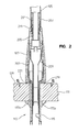
FIG. 2 is a cross-sectional view taken along line 2-2 of FIG. 1;
FIG. 3 is a detailed cross-sectional view of a portion of FIG. 2;
FIG. 4 is a cross-sectional view of the faucet assembly taken along line 4-4 of FIG. 1, with the handle removed to show the mixing valve;
FIG. 4A is a detailed view of a portion of FIG. 4;
FIG. 5 is a cross-sectional view of the faucet assembly taken along line 5-5 of FIG. 2;
FIG. 6 is a side perspective view of a mounting tube and adapter according to an embodiment of the present disclosure;
FIG. 7 is a side perspective view of a sleeve and anchor assembly according to an embodiment of the present disclosure;
FIG. 8 is an exploded perspective view of a faucet assembly according to an embodiment of the present disclosure;
FIG. 9 is an exploded perspective view of a mounting tube and adapter according to an embodiment of the present disclosure;
FIG. 10 is an exploded perspective view of a mounting tube, sleeve, and anchor assembly according to an embodiment of the present disclosure;
FIG. 11 is a bottom perspective view of a faucet assembly and a handle assembly according to an embodiment of the present disclosure;
FIG. 12 is a cross-sectional view of the handle assembly taken along line 12-12 of FIG. 11;
FIG. 13 is a cross-sectional view of the handle assembly taken along line 13-13 of FIG. 11;
FIG. 14 is a detailed cross-sectional view of a portion of FIG. 12;
FIG. 15 is an exploded perspective view of the anchor and top mounting structure of the handle assembly of FIG. 11;
FIG. 16 is top perspective view of the anchor and top mounting structure of the handle assembly of FIG. 11;
FIG. 17 is a cross sectional view of the faucet taken along line 17-17 of FIG. 11;
FIG. 18 is a detailed cross-sectional view of a portion of FIG. 17;
FIG. 19 is an exploded perspective view of the anchor and bearing of FIG. 19;
FIG. 20 is a top view of the faucet with bearing and the anchor according to an embodiment of the present disclosure; and
FIG. 21 is a cross sectional view of the anchor structure of the faucet taken along line 21-21 of FIG. 11.
Corresponding reference characters indicate corresponding parts throughout the several views. Unless otherwise stated, the drawings are proportional. The exemplifications set out herein illustrate exemplary embodiments of the disclosure and such exemplifications are not to be construed as limiting the scope of the disclosure in any manner.
DETAILED DESCRIPTION OF THE DRAWINGS
The embodiments of the disclosure described herein are not intended to be exhaustive or to limit the disclosure to precise forms disclosed. Rather, the embodiment selected for description have been chosen to enable one skilled in the art to practice the disclosure.
Referring initially to FIGS. 1-10, and with particular reference to FIG. 9, a faucet assembly 101 is shown. An anchor 115 is mounted to a mounting deck 111. The mounting tube 207 is positioned within a faucet assembly 101 or faucet support, including the delivery spout 107, and the adapter 201 and the clutch 211 are installed in the mounting tube 207 inside the delivery spout 107. The sleeve 209 may optionally be installed in the mounting tube 207, and guides conduits through the mounting tube 207 and the anchor 115. In operation, the delivery spout 107 with the mounting tube 207 including the adapter 201 and the clutch 211 are positioned over the anchor 115, so that the fingers 403 of the mounting tube 207 are adjacent to the lip 405 of the anchor 115. The adapter 201 is rotated, drawing the mounting tube 207 into the delivery spout 107 and reducing the diameter of opening in the mounting tube containing the fingers 403. The fingers 403 engage with the lip 405 of the anchor 115, forcing the delivery spout 107 towards the mounting deck 111, so that the delivery spout 107 is in releasable communication with the anchor 115. The neck adapter 203 includes fingers that engage with the adapter 201 and the neck 105, so that rotation of the neck 105 does not rotate the adapter 201 (i.e., the neck 105 may freely rotate without rotating the other components of the faucet assembly 101).
The illustrative embodiment of a faucet assembly 101 is shown as including an upper faucet assembly 102 positioned above an anchor assembly 113. The upper faucet assembly 102 illustratively includes a body housing or delivery spout 107 including a mixing valve 407 coupled to a handle 109, and a neck 105 in communication with a pull-out spray head 103 (i.e., detachable from the neck 105 of the delivery spout 107). The mixing valve 407 is fluidly coupled to a waterway assembly 119 a, 119 b, and 121, which provides fluid communication to hot and cold water supplies (not shown). The waterway assembly 119 a, 119 b, and 121 also illustratively provides fluid communication between an outlet of the mixing valve 407 and the pull out spray head 103. An anchor 115 is secured to a lower portion of the delivery spout 107. The anchor assembly 113 includes an anchor body 115 which receives fasteners 403 to couple the anchor 115 to the delivery spout 107, shown in FIG. 4. The anchor 115 also includes cleats 117 a and 117 b to secure the anchor 115 to the lower surface 127 of the mounting deck 111. Described more fully below, the cleats 117 a and 117 b ride longitudinally in a track 133 disposed in the anchor 115. Inlet conduits (119 a shown in FIG. 1, 119 b shown, for example, in FIGS. 1 and 4) may supply, for example, water from hot and cold water sources (not shown) to the mixing valve 407. The mixing valve 407 may adjust the flow from the inlet conduits 119 a and 119 b, and the mixed sources may flow into an outlet conduit 121 fluidly coupled to the spray head 103.
With further reference to FIG. 1, a handle 109 is coupled to a stem 409 of the mixing valve 407 in a conventional manner, for example, through the use of a set screw (not shown). The mixing valve 407 controls the rate and relative proportion of water flowing from cold and hot water inlet conduits 119 a and 119 b, of the waterway assembly 20 to outlet conduit 121. The mixing valve 18 may be of conventional design, and illustratively of the type disclosed in U.S. patent application Ser. No. 11/494,889, filed Jul. 28, 2006, entitled “MIXING VALVE,” incorporated by reference herein. Similarly, the waterway assembly may be of conventional design, and illustratively of the type disclosed in U.S. patent application Ser. No. 11/700,634, filed Jan. 31, 2007, entitled “FAUCET INCLUDING A MOLDED WATERWAY ASSEMBLY,” incorporated by reference herein.
Each of the inlet conduits 119 a and 119 b illustratively includes an end connector (not shown) configured to couple to a fluid coupling for supplying water from hot and cold water sources (not shown). The fluid couplings may comprise a quick release coupling, such as PMC Series couplings available from Colder Products Company of St. Paul, Minn. Other conventional fluid couplings may be substituted therefor, such as those detailed in U.S. Pat. No. 6,672,628.
Illustratively, the inlet conduits 119 a and 119 b are formed of a flexible tubular material to facilitate positioning of the respective end connectors (not shown) relative to the faucet assembly 101. In one illustrative embodiment, the inlet conduits 119 a and 119 b and outlet conduit 121 are all formed of cross-linked polyethylene (PEX).
With reference to FIGS. 2 and 3, the anchor 115 is supported by a mounting deck 111, typically a countertop or sink deck having one or more access openings. As detailed herein, a coupler or guide releasably couples the upper faucet assembly 102 to the anchor 115.
With reference to FIGS. 7, 8, and 10, the anchor 115 illustratively includes an anchor floor portion 219 which is mounted from the top of the mounting deck 111 and rests on the upper surface 129 thereof. It should be noted that the anchor 115 may also be mounted from the underside of the mounting deck 111 below its lower surface. The anchor 115 may include a void 707 to receive the waterway assembly 615, or the inlet conduits 119 a and 119 b and the outlet conduit 121. The anchor may also comprise one or more projections 613 or other structures for receiving the mounting tube 207 in limited orientations. For example, the projections 613 may receive structures on the mounting tube 207, such as voids 611, to allow the mounting tube 207 to be installed on the anchor 115 in only one orientation.
First and second attachment posts 217 a and 217 b extend downwardly from the anchor 115. The attachment posts 217 a and 217 b each include a plurality of external threads and are configured to operably couple with the cleats 117 a and 117 b. An upper end of each post 217 a and 217 b extends through the anchor 115 and includes a head configured to be manipulated by a tool, such as a screwdriver or Allen wrench (not shown). Upper and lower apertures 711 and 709 receive each attachment post 217 a and 217 b, respectively. The upper apertures 711 and the lower apertures 709 are formed within the anchor 115. Further, the anchor includes grooves 133 (shown for attachment post 217 a, not shown for attachment post 217 b) for each of the attachment posts 217 a and 217 b. Grooves 133 are configured to receive the respective attachment post 217 a and 217 b and guide the respective cleats 117 a and 117 b in movement longitudinally therealong. In one illustrative embodiment, the anchor 115 is formed, for example, through molding of a thermoplastic material.
The mounting plate cleats 117 a and 117 b each include a threaded opening configured to threadably engage the respective attachment post 217 a and 217 b. Each cleat 117 a and 117 b is substantially wedge shaped and includes an upper surface 703 configured to cooperate with the anchor floor portion 219 to clamp the anchor 115 to the mounting deck 111. When the anchor 115 is positioned on the mounting deck 111, the threaded attachment posts 217 a and 217 b are rotated to cause the mounting plate cleats 117 a and 117 b to move longitudinally up and down on the posts 217 a and 217 b, respectively. Illustratively, counterclockwise rotation of attachment posts 217 a and 217 b causes cleats 117 a and 117 b to move downwardly or away from mounting deck 111 to an unlocked position. The cleats 117 a and 117 b may be directed inside of the anchor 115, in a respective support structure (shown as 705 for cleat 117 a, not shown for cleat 117 b). The support structures 705 allow the cleats 117 a and 117 b to enter the anchor 115 during installation, so that the cleats 117 a and 117 b do not interfere with the walls of the void created in the mounting deck 111 to install the anchor 115. The shape of the support structures 705 conform to the cross-sectional shape of cleats 117 a and 117 b
Clockwise rotation of attachment posts 217 a and 217 b causes cleats 117 a and 117 b to move upwardly or toward mounting deck 111 to a locked position. In the locked position, the upper surfaces 703 of the cleats 117 a and 117 b abuts the bottom or lower surface 127 of mounting deck 111, securing the anchor 115 thereto.
The cleats 117 a and 117 b are prevented from rotating with the attachment posts 217 a and 217 b as they are turned, by guide surfaces 711 of each cleat 117 a and 117 b. The guide surfaces 711 abut against cooperating stop surfaces 713 of the grooves 133, upon rotation of the cleats 117 a and 117 b, respectively. This causes cleats 117 a and 117 b to ride up or down the attachment posts 217 a and 217 b within the grooves 133 as they are rotated instead of rotating 360 degrees with the rotation of the posts 217 a and 217 b. As noted above, attachment posts 217 a and 217 b are stabilized and secured at their bottom portions by the anchor 115 body.
The mounting tube 207 (shown particularly in FIGS. 6, 8, 9, and 10) may be formed from a thermoplastic material. The mounting tube 207 is a hollow cylindrical shape and includes a hollow inner portion and an outer portion. The top of the mounting tube 207 may include internal threads 223 disposed on the surface of the inner portion, and the threads 223 of the mounting tube 207 may engage similarly sized external threads 205 on the adapter 201. The diameter of the mounting tube 207 may increase from the top of the mounting tube 207 to the bottom of the mounting tube 207, to conform to the inner shape of the spout 107, and the bottom of the mounting tube 207 may include one or more resilient fingers 403 to secure the mounting tube 207 to the anchor 115. The fingers 403, shown particularly in FIGS. 4, 4A, 6, 8, and 9, may extend outwardly from the longitudinal axis of the mounting tube 207, although may flex inwardly, toward the longitudinal axis of the mounting tube 207, if force is applied to the fingers 403, that is, the fingers 403 may be inwardly biased. The fingers 403 may include a flat surface to engage with the anchor lip 405.
In certain illustrative embodiments, the fingers 403 are biased radially inwardly. The fingers 403 may include one or more projections having an engagement surface 413, shown particularly in FIGS. 4 and 4A, and the engagement surface 413 may releasably engage with the bottom surface of the anchor lip 405. Shown in greater detail below, the diameter of the bottom portion of the mounting tube 207 with the fingers 403 may be larger than the diameter of the anchor body 115, so that the mounting tube 207 may be positioned over the anchor body 115. If force is applied to the outer surface of the mounting tube 207, such as by the delivery spout 107 during installation, the fingers 403 may flex inwardly toward the center of the mounting tube 207. The engagement surface 413 of the fingers 403 may engage the bottom surface of the anchor lip 405, preventing the mounting tube 207 from being removed from the anchor 115 body, shown in FIG. 4A.
The delivery spout 107 (shown in FIGS. 1-4) may be a metal or a plastic material, and may enclose the components of the upper faucet assembly 102, e.g., the outlet tube may be slidably received within the delivery spout 107. The delivery spout 107 may include an opening for the mounting tube 207, an opening for the adapter 201, and an opening for the neck 105. The mixing valve 407 may be disposed within the delivery spout 107, and the mixing valve 407 may be releasably engaged to the delivery spout 107 with a decorative cap 131 or bonnet nut. The decorative cap 131 may include threads that may engage with threads on the mounting body, releasably engaging the delivery spout 107 to the decorative cap 131 and retaining the mixing valve 407 within the delivery spout 107.
The sleeve 209 may be a plastic material, and may by cylindrical and have a hollow inner surface and an outer surface. The center portion of the sleeve 209 may guide the pull-out hose 225 through the mounting tube 207 and through the anchor 115, and the outer surfaces of the sleeve 209, particularly the wings 501 (shown particularly in FIGS. 7, 8, and 10) may guide the inlet conduits 119 a and 119 b and the outlet conduit 121 through the mounting tube 207 and through the anchor 115 to the lower surface 127 of the mounting deck 111. Shown in FIG. 5, the wings 501 of the sleeve 209 may position the inlet conduits 119 a and 119 b and the outlet conduit 121 so that the inlet conduits 119 a and 119 b and the outlet conduit 121 do not tangle or deviate from predefined indentations within the anchor body 115, and ensures that the inlets and the return are separated from the hose 225 positioned within the sleeve 209. The hose 225 within the sleeve 209 may extend and retract as the spray head 103 is uncoupled and removed from the neck 105, and replaced and coupled within the neck 105 during operation. If the hose 225 and the inlet conduits 119 a and 119 b and the outlet conduit 121 were not separated, the motion of the hose 225 may scrape and/or wear the inlet conduits 119 a and 119 b and the outlet conduit 121. Shown in FIGS. 4 and 6, the sleeve 209 also includes one or more projections 213 at the top of the sleeve 209. The one or more projections 213 releasably engage with one or more voids 603 in the mounting tube 207, so that the sleeve 209 is inserted within the mounting tube 207, and the one or more projections 213 engage with the voids 603 of the mounting tube 207, releasably seating the sleeve 209 within the mounting tube 207.
The waterway assembly 615 includes the inlet conduits 119 a and 119 b and the return conduit 121, as well as a coupling element 601 that fluidly couples the inlet conduits 119 a and 119 b and the outlet conduit 121 to the mixing valve 407. The inlet conduits 119 a and 119 b may each be a hollow tube for carrying liquid from a water source (not shown) to the mixing valve 407. The outlet conduit 121 may be a hollow tube, and may carry liquid from the mixing valve 407 to the spray head 103. The coupling element 601 may form one end of each of the inlet conduits 119 a and 119 b and the outlet conduit 121. The coupling element 601 may include a deformable gasket formed from an elastomeric material to seal the inlet conduits 119 a and 119 b and the outlet conduit 121 to the mixing valve and separate the inlet conduits 119 a and 119 b and the outlet conduit 121 from mixing before reaching the mixing valve 407.
The adapter 201 may be metal or plastic. The adapter 201 may be cylindrical and may include external threads 205 on a lower portion that may threadably engage the internal threads 223 of the mounting tube 207. The adapter 201 may also include one or more projections 301, shown in FIGS. 3 and 8, that engage with the clutch 211, or one or more surfaces 901 that engage with complimentary surfaces 903 on the clutch 211, so that rotation of the adapter 201 may rotate the clutch 211 when the adapter 201 is installed in the clutch 211. The adapter 201 may also include one or more projections 605 that may allow projections 605 on the clutch 211 to releasably engage the adapter 201, holding the adapter 201 in place after installation of the adapter 201. The adapter 201 may include one or more features that may engage projections on the neck adapter 203.
Shown in FIGS. 3, 6, and 8, the clutch 211 may be plastic or another material. The clutch 211 may include clutch fingers 605 and clutch projections 607 on the outer surface of the clutch 211 and one or more projections on the inner surface of the clutch. Installed within the delivery spout 107, the clutch fingers 605 may abut a lip 303 or other projection on the inner surface of the delivery spout 107, and may releasably attach the clutch 211 to the delivery spout 107. The inner surface of the delivery spout 107 may be formed such that the clutch projections 607 selectively engage and release the inner surface of the delivery spout 107 when the clutch 211 is rotated within the delivery spout 107. For example, and without limitation, the inner surface of the delivery spout 107 may be hexagonal in shape. The clutch projections 607 may be shaped so that the clutch projections 607 rest in the area formed by the angles of the hexagonal delivery spout 107 inner surface, and resist clockwise or counterclockwise movement. The clutch projections 607 may deform when the clutch 211 is rotated within the delivery spout 107, and may return to an original shape when resting in the area formed by the angles of the hexagonal delivery spout 107 inner surface. The clutch 211 may be rotated within the delivery spout 107, but the clutch 211 may be biased to rest so that the clutch projections 607 rest within the areas formed by the angles of the hexagonal delivery spout 107 inner surface.
The neck adapter 203 may be a plastic material, and may include one or more projections 905 on the outer surface that releasably engage with one or more projections 415 on the inner surface of the neck 105 so that the neck 105 is releasably engaged with the neck adapter 203. The neck adapter 203 may also include one or more projections 305 on the inner surface of the neck adapter 203 that rotatably engage with one or more surfaces 907 of the adapter 201 to allow the neck adapter 203 to rotate freely around the adapter 201, such that rotation of the neck adapter 203 does not rotate the adapter 201 or the clutch 211. When the neck 105 is installed on the neck adapter 203, the neck 105 is in communication with the neck adapter 203, so that rotation of the neck 105 rotates the neck adapter 203. Rotation of the neck adapter 203, however, does not rotate the adapter 201, as the projections 305 of the neck adapter ride in the surfaces 907 of the adapter 201.
The neck 105 may be a metal or plastic material, and may be similar to the material of the delivery spout 107. The neck 105 may be substantially hollow, and may allow the tube to pass through the neck 105.
The spray head 103 may be of a conventional type, and may include a shell or housing formed of a metal or plastic material. The material may be similar to the material of the delivery spout 107 and the neck 105. The spray head 103 may include inserts, such as an aerator and/or nozzles, to provide stream and spray modes for liquid delivery.
Shown in FIG. 8, to mount the anchor 115 onto the mounting deck 111, the mounting adapter is positioned over the opening of the mounting deck 111. In one embodiment, the mounting adapter is not used, and the anchor 115 is mounted directly to the mounting deck 111. To mount the anchor 115, the cleats 117 a and 117 b are oriented in retracted positions and are nested within respective supports, and the anchor 115 body is passed through the opening of the mounting adapter and the mounting deck 111 from above. The attachment posts 217 a and 217 b are rotated clockwise such that the cleats 117 a and 117 b rotate out of the anchor 115 to extended positions outside of respective supports. Continued clockwise rotation causes the cleats 117 a and 117 b to move upwardly along the length of the respective post 217 a and 217 b such that the upper surfaces 703 of the cleats 117 a and 117 b engage the lower surface 127 of the mounting deck 111, and the anchor floor portion 219 engages the mounting adapter, thereby clamping the mounting adapter and the mounting deck 111 between the upper surfaces of the cleats 117 a and 117 b and the anchor 115 floor portion 219.
With respect to FIG. 9, the clutch 211 is attached to the delivery spout 107 by pushing the clutch 211 through the top of the delivery spout 107 until the clutch fingers 605 engage with the inner surface of the delivery spout 107. The adapter 201 may be inserted through the opening in the clutch 211, such that the threads 205 of the adapter 201 may extend into the delivery spout 107. Projections on the inner surface of the clutch may releasably engage with the threads 205 of the adapter 201, preventing the adapter 201 from being removed from the delivery spout 107. The adapter 201 and/or the threads 205 of the adapter 201 may be formed so that the rotation of the adapter 201 may rotate the clutch 211. In one embodiment, surfaces 903 inside of the clutch 211 may engage with complimentary surfaces 901 of the adapter 201 in a way that the rotation of the adapter 201 may rotate the clutch 211. The neck adapter 203 may be positioned over the adapter 201, and one or more projections 305 of the neck adapter 203 may releasably engage one or more indentations 907 of the adapter 201. The neck adapter 203 may freely rotate about the adapter 201, so that rotation of the neck adapter 203 does not rotate the clutch 211.
Shown with respect to FIG. 10, the sleeve 209 may be installed within the mounting tube 207. The projections 213 of the sleeve 209 may releasably engage with the voids 603 of the mounting tube 207. The rear wing 701 of the sleeve 209 may abut the inner surface of the mounting tube 207, positioning the sleeve 209 within the mounting tube 207.
The mounting tube 207 may then be positioned within the delivery spout 107. The mounting tube 207 may be positioned so that the mounting tube 207 hose void 609 may be positioned next to the waterway inlet 411 of the delivery spout 107. The inlet conduits 119 a and 119 b and the outlet conduit 121 may be inserted through the waterway inlet 411 of the delivery spout 107, and may continue through the mounting tube 207 hose void 609 and into the mounting tube 207. The wings 501 of the sleeve 209 may align the inlet conduits 119 a and 119 b and the outlet conduit 121 within the mounting tube 207, and may prevent the inlets and the return from twisting. The threads 205 of the adapter 201 may engage the threads 223 of the mounting tube 207 within the delivery spout 107. The mounting tube 207 may be prevented from rotating 360 degrees within the delivery spout 107 by the inlet conduits 119 a and 119 b and the outlet conduit 121 extending through the delivery spout 107 and into the mounting tube 207 through the mounting tube 207 hose void 609. The adapter 201 may be rotated, and the threads 205 of the adapter 201 may engage with the threads 223 of the mounting tube 207. As the mounting tube 207 is constrained from rotating 360 degrees, the mounting tube 207 is drawn into or out of the delivery spout 107 on a longitudinal axis when the adapter 201 is rotated. The mounting tube 207 may be drawn into the delivery spout 107 so that the fingers 403 of the mounting tube 207 may extend from the bottom of the delivery spout 107.
Next, shown with respect to FIGS. 6, 8, and 10, the delivery spout 107, clutch 211, neck adapter 203, adapter 201, mounting tube 207, and inlet conduits 119 a and 119 b and outlet conduit 121 are positioned above the anchor 115. The inlet conduits 119 a and 119 b and the outlet conduit 121 are positioned so that the inlets and the return extend out of the bottom of the delivery spout 107, to the upper surface 129 of the mounting deck 111, through the mounting adapter, through the anchor 115, and to the lower surface 127 of the mounting deck 111. The opening of the mounting tube 207 is sized to be larger than the upper portion of the anchor 115. The projections 613 of the anchor 115 may be positioned within the voids 611 located in the mounting tube 207, so that the mounting tube 207 may be positioned over the anchor 115 in one orientation. The fingers 403 of the mounting tube 207 may be positioned to abut the anchor 115 floor portion 219, and may rest on the anchor 115 floor portion 219.
The adapter 201 may be rotated, so that the threads 205 of the adapter 201 engage the threads 223 of the mounting tube 207. The neck adapter 203 may be positioned around the portion of the adapter 201 extending out of the delivery spout 107, so that the rotation of the adapter 201 may include the use of a tool able to releasably engage with one or more structures on the adapter 201. In one embodiment, one or more voids in the adapter 201 may engage with one or more projections of a tool, to enable the tool to rotate the adapter 201. The engagement of the threads 205 of the adapter 201 and the threads 223 of the mounting tube 207 may move the mounting tube 207 into the delivery spout 107. The opening of the delivery spout 107 may be narrower than the opening of the mounting tube 207, so that when the mounting tube 207 is drawn into the delivery spout 107, the fingers 403 of the mounting tube 207 may be pressed together by the narrower delivery spout 107. The fingers 403 may close together, so that the diameter of the mounting tube 207 opening may become smaller. The fingers 403 may engage with the lip 405 of the anchor 115 as the diameter of the mounting tube 207 becomes smaller. The adapter 201 may continue to be rotated until the body indentation 221 abuts the anchor floor 219, as shown in FIGS. 2 and 3. The fingers 403 engaged with the lip 405 of the anchor 115 may prevent the delivery spout 107 from being removed from the anchor 115. When the body indentation 221 abuts the anchor floor 219, the adapter 201 may not be able to be rotated further, which may prevent overtightening. When the body indentation 221 abuts the anchor floor 219, the delivery spout 107 may substantially abut the upper surface of the mounting adapter or the upper surface of the mounting deck 111. When the body indentation 221 abuts the anchor floor 405, the tool may be removed.
If the delivery spout 107 is to be removed from the anchor 115, for example for refitting or deinstallation, the adapter 201 may be rotated in the opposite direction as the adapter 201 was rotated to install the delivery spout 107 to the anchor 115. The threads 205 of the adapter 201 may engage with the threads 223 of the mounting tube 207, and may move the mounting tube 207 away from the adapter 201, and out of the delivery spout 107. Moving the mounting tube 207 away from the adapter 201 may cause the fingers 403 to expand away from one another as they become disengaged from the lip 405 of the anchor 115. The diameter of the opening of the mounting tube 207 may increase, and the diameter increase may allow the fingers 403 to become disengaged from the lip 405 of the anchor 115. The mounting tube 207 and delivery spout 107 may be removed from the anchor 115 when the fingers 403 are disengaged from the lip 405 of the anchor 115.
The anchor 115 may also be removed from the mounting deck 111. To remove the anchor 115, the attachment posts 217 a and 217 b are rotated counterclockwise, so that the cleats 117 a and 117 b move downwardly along the length of the posts 217 a and 217 b, disengaging the cleats 117 a and 117 b from the lower surface of the mounting deck 111. The posts may continue to be rotated counterclockwise, and the cleats 117 a and 117 b may continue to move downwardly along the length of the posts until the cleats 117 a and 117 b reach their respective supports 705, and rotate into the anchor 115 within the supports 705. The anchor 115 may then be lifted out of the hole in the mounting deck 111. The mounting adapter may be removed from the mounting deck 111 as well.
In an alternate embodiment, shown in FIGS. 11-21, a further illustrative spout including a delivery spout and a handle are shown mounted to mounting deck 111. With respect to FIG. 11, the valve structure 1103 is mounted to the mounting deck 111. Inlet conduits 119 a and 119 b carry fluid from below the mounting deck 111, through the valve anchor structure 1113, and to a valve, where the fluids are mixed in a proportion selected by the valve, and the combined fluids are passed in an outlet conduit through the valve anchor structure 1113 and below the mounting deck 111. The spout structure 1101 is mounted to the mounting deck 111 beside the valve structure 1103 with a spout anchor structure 1115, which allows the return conduit to pass through the spout anchor structure 1115 and into the spout structure 1101.
The spout structure 1101 and the valve structure 1103 are mounted to the mounting deck 111 with a spout anchor structure 1115 and a valve anchor structure 1113, respectively. The spout structure 1101 and the valve structure 1103 are shown together mounted to a mounting deck in FIG. 11.
With respect to the valve structure 1103, shown in FIGS. 11-16, the anchor structure 1113 for the handle may be similar to the anchor 113 previously shown, however instead of an anchor lip 405 securing the mounting tube 207, the valve anchor 1113 may provide external threads 1223 to releasably secure the housing 1109 to the valve anchor 1113. The valve anchor cleats 117 a and 117 b may releasably engage the bottom surface 127 of the mounting deck 111, and, in an embodiment, may include a ring 1211 separating the bottom surface of the anchor 1113 with the top surface 1215 of the mounting deck 111, so that the ring 1211 is engaged with the top surface 1215 of the mounting deck 111 and the surface of the anchor 1113. The anchor threads 1223 may be used to releasably secure the housing 1109 to the valve anchor 1113, and thus the valve structure 1103 to the valve anchor 1113, as more fully explained below.
The ring 1211 may be a metal or plastic ring, and has an internal void so that the ring 1211 surrounds the valve anchor 1113, and is located adjacent to the upper surface 1215 of the mounting deck. In the embodiment shown in FIG. 13, the ring 1211 includes ring snap fingers 1303 that extend through the valve anchor 1113 at anchor openings 1303, and releasably engage with the valve anchor 1113 to secure the ring 1211 to the valve anchor 1113. The ring 1211 may include a lip 1305 that may interface with a complimentary lip 1307 on the housing 1109 to prevent the valve anchor 1113 from being seen from outside of the housing 1109 when the housing 1109 is installed on the valve anchor 1113.
Inlet conduits 119 a and 119 b shown in FIGS. 15 and 16 may supply, for example, water from hot and cold water sources (not shown) to the mixing valve 1207. The mixing valve 1207 may adjust the flow from the inlet conduits 119 a and 119 b based on the position of the stem 1205, and the mixed sources may flow into the outlet conduit 121.
The mixing valve 1207, in the embodiment, is in communication with a keying ring 1227 that surrounds the mixing valve 1207. In the embodiment, the keying ring 1227 is fixed with respect to the mixing valve 1207. The keying ring 1227 has an internal void to allow the inlet conduits 119 a and 119 b and the outlet conduit 121 to pass through, and includes one or more projections or indentations that interact with complimentary projections or indentations on the valve anchor 1113, so that the projections or indentations on the keying ring 1227 and on the valve anchor 1113 fit together in only one orientation. That is, the keying ring 1227 and the mixing valve 1207 that the keying ring 1227 is fixed to must be rotated until the projections or indentations of the keying ring 1227 match with the complimentary projections or indentations of the valve anchor 1113, allowing the mixing valve 1207 to fit into the valve anchor 1113 in one orientation.
The housing 1109 may be a metal or a plastic, and may be in the shape of a cylinder. The first opening 1235 includes threads 1221 disposed on the inner surface of the housing 1109, which are adapted to engage threads 1223 located on the valve anchor 1113. The surface of the housing 1109 near the second opening 1229 curves inward at 1231, so that the second opening 1229 is a smaller diameter than the first opening 1235. The narrowing diameter of the housing 1109 from the first opening 1235 to the second opening 1229 forms a portion of the inner surface 1231 that retains the mixing valve 1207 during installation, preventing the mixing valve 1207 from being removed from the second opening 1229. In an embodiment, the outer surface of the second opening 1229 contains projections or indentations that may engage a tool with complimentary projections or indentations, so that the tool may releasably grip the outer surface and allow the tool to rotate the housing 1109. The stem 1205 of the mixing valve 1207 extends through the second opening 1229.
During installation of the handle assembly 1103, the mixing valve 1207 and the keying ring 1227 are positioned within the housing 1109 so that the stem 1205 of the mixing valve 1207 extends out of the second opening 1229 of the housing 1109. The mixing valve 1207 may be inserted into the housing 1109 through the first opening 1235, as the second opening 1229 is dimensioned to be too narrow for the mixing valve 1207 to pass through.
The ring 1211 is pressed onto the bottom surface of the valve anchor 1113, so that the ring snap fingers 1303 flex outwardly and pass through the anchor openings 1301. When the projections on the ring snap fingers 1303 reach the inner surface of the valve anchor 1113 through the anchor openings 1301, the ring snap fingers 1303 flex inwardly so that the projections abut the inner surface of the valve anchor 1113, releasably fixing the ring 1211 to the valve anchor 1113.
To mount the valve anchor 1113 onto the mounting deck 111, the cleats 117 a and 117 b are oriented in retracted positions and are nested within respective supports, and the anchor 1113 is passed through the mounting deck 111 from above. The ring bottom surface 1219 is sized so that it is wider than the opening through the mounting deck 111, or additional material is used to fill in the opening through the mounting deck so that the ring bottom surface 1219 contacts the upper surface 1215 of the mounting deck 111. The attachment posts 217 a and 217 b are rotated clockwise such that the cleats 117 a and 117 b rotate out of the anchor 115 to extended positions outside of respective supports. Continued clockwise rotation causes the cleats 117 a and 117 b to move upwardly along the length of the respective post 217 a and 217 b such that the upper surfaces 703 of the cleats 117 a and 117 b engage the lower surface 127 of the mounting deck 111, and the anchor floor portion 219 engages the mounting adapter, thereby clamping the mounting adapter and the mounting deck 111 between the upper surfaces of the cleats 117 a and 117 b and the anchor 115 floor portion 219.
The inlet conduits 119 a and 119 b, shown in FIGS. 15 and 16, and the outlet conduit 121 are positioned to extend through the void in the anchor 1113 from the top surface 1215 of the mounting deck 111 to the bottom surface 127 of the mounting deck 111. The mixing valve 1207 and the housing 1109 are positioned so that the projections or indentations of the keying ring 1227 match with the projections or indentations of the anchor 1113, indicating a correct positioning of the keying ring 1227 and the mixing valve 1207. The inner threads 1221 of the housing 1109 contact the outer threads 1223 of the anchor 1113, and the housing 1109 is rotated so that the inner threads 1221 of the housing 1109 and the outer threads 1223 of the anchor 1113 are in communication with one another. The housing 1109 may be tightened by a tool (not shown). When tightened, the lip 1307 of the housing 1109 is positioned over the lip 1305 of the anchor 1113, obstructing the view of the anchor 1113 from the outside of the valve structure 1103. The handle 1107 is attached to the stem 1205 and held in place with a set screw 1203. A user may operate the handle 1107 to manipulate the stem 1205 and the mixing valve 1207 to change flow and the mixture of liquid from the inlet conduits 119 a and 119 b to the outlet conduit 121.
The spout structure 1101, shown in FIGS. 11 and 17-21, may also be mounted to the mounting deck. The spout structure 1101 is mounted to the deck with a spout anchor structure 1115, described below.
The anchor structure 1115 for the spout 1105 may be similar to the anchor structure 113 previously shown, however instead of an anchor lip 405 securing the mounting tube 207, the spout anchor 1115 may contain one or more windows 1715 to provide a releasable attachment for one or more fingers 1713 of a bearing 1711 in communication with the spout structure 1101. The spout anchor cleats 117 a and 117 b may releasably engage the bottom surface 127 of the mounting deck 111, and, in an embodiment, may include an insulator ring 1701 separating the top surface of the anchor 1103 from the top surface 1215 of the mounting deck 111, so that the ring 1701 is engaged with the top surface 1215 of the mounting deck 111 and the anchor 1103.
The ring 1701 is illustratively formed of a non-conductive material (e.g., electrically non-conductive plastic), and has an internal void so that the ring 1701 surrounds the anchor 1115, and is located adjacent to the upper surface 1215 of the mounting deck 111. In an embodiment, the ring 1701 includes ring snap fingers (not shown) that extend through the anchor 1115 at anchor openings (not shown), and releasably engage with the anchor 1115 to secure the ring 1701 to the anchor 1115. The ring 1701 may include a lip 1725 that may interface with the first opening of the spout 1105 to prevent the anchor 1115 from being seen from outside of the spout 1105 when the spout 1105 is installed on the anchor 1115. The ring 1701 may also include a groove 1729 into which may be disposed an elastomeric or foam gasket 1730. The elastomeric or foam gasket 1730 may extend below the lower surface of the ring 1701, so that it may be in contact with the upper surface 1215 of the mounting deck 111. The elastomeric or foam gasket 1730 may deform during installation to create a seal between the ring 1701 and the upper surface 1215 of the mounting deck 111. In an embodiment, the elastomeric or foam gasket 1730 may be formed in a different shape, and may include one or more projections interacting with the groove 1729 to hold the member in place when positioned on the ring 1701.
A set ring 1721 may be received within with the spout 1105, and may, in an embodiment, be fixed in the spout 1105 by brazing or other permanent mounting. The set ring 1721 may be fixed in relation to the spout 1105 so that when the spout 1105 rotates, the set ring 1721 also rotates. The set ring 1721 may be cylindrical and may have an internal void. The set ring 1721 contains a portion 1735 that interferes with a projection 1707 on the anchor to form a limit stop, preventing the spout 1105 from a full range of rotation about the anchor 1115. The set ring 1721 contains threads 1721 positioned on the inner surface of the set ring 1721, which interact with external threads 1723 on the connector tube 1709.
The connector tube 1709 may be a metal, such as brass. The connector tube 1709 is cylindrical and hollow, and contains tube threads 1723 located on the outer surface. The tube threads 1723 engage with the threads 1721 of the set ring 1703, releasably engaging the connector tube 1709 to the set ring 1703. The connector tube 1709 also contains a groove 1727 or a tube lip into which an elastomeric o-ring 1705 may be deposited. The o-ring 1705 may be sized so that it deforms when installed and the connector tube 1709 presses the o-ring 1705 against the inner surface of the anchor 1115. Proximate on opposite end of the connector tube 1709 as the threads 1723, the connector tube 1709 contains a groove 1719 to interact with one or more fingers 1717 of the bearing 1711, allowing the bearing 1711 to rotate relative to the connector tube 1709.
The bearing 1711 is cylindrical, and may be formed of a plastic material. The bearing 1711 contains inward facing fingers 1717 and outward facing fingers 1713. The inward facing fingers 1717 engage with the groove 1719 on the outer surface of the connector tube 1709, such that the connector tube 1709 may rotate freely around the bearing 1711. When the connector tube 1709 and bearing 1711 are installed within the anchor 1115, the outward facing fingers 1713 flex inward while the bearing 1711 travels the length of the anchor 1115, and flex outward to engage with the anchor windows 1715. The outward facing fingers 1713 are angled so that an amount of upward force will flex the outward facing fingers 1713 inwardly and remove the outward facing fingers 1713 from the anchor windows 1715. The inward facing fingers 1717 are angled so that disengagement of the inward facing fingers 1717 from the groove 1719 on the outer surface of the connector tube 1709 requires more force than disengagement of the outward facing fingers 1713 from the anchor windows 1715. This allows for disassembly or removal, so that the user may apply upward force to the spout 1105, and the outward facing fingers 1713 disengage from the anchor windows 1715 before the inward facing fingers 1717 disengage from the groove 1719 on the outer surface of the connector tube 1709, allowing the bearing 1711 to remain in communication with the connector tube 1709 while the connector tube 1709 and spout 1105 are lifted out of the anchor 1115.
The spout 1105 may be a metal or a plastic, and may be in the shape of a cylinder. The spout 1105 is hollow to allow for the outlet conduit 121 to extend from the bottom surface 127 of the mounting deck, through the anchor 1115, through the connector tube 1709, into the first opening 1731 of the spout 1105, through the spout 1105, and to the second opening 1733 of the spout 1105. The outlet conduit 121 may terminate with an aerator or other liquid management device. In an embodiment, the outlet conduit 121 is fixed within the spout 1105. In another embodiment, the outlet conduit 121 is not fixed, may be attached to a removable device such as a sprayer, and may be pulled out of the second opening 1733.
During installation of the spout assembly 1101, the set ring 1703 is fixed within the spout 1105, near the first opening 1731. The connector tube 1709 is installed in the spout 1105, so that the threads of the connector tube 1709 engage with the threads of the set ring 1703. The o-ring 1705 may be placed on the tube, 1709 and be partially constrained by a lip 1727 or other projection on the connector tube 1709.
The ring 1701 is pressed onto the bottom surface of the anchor 1115, so that the ring snap fingers flex outwardly and pass through the anchor openings. When the projections on the ring snap fingers reach the inner surface of the anchor through the anchor openings, the ring snap fingers flex inwardly so that the projections abut the inner surface of the anchor, releasably fixing the ring 1701 to the anchor 1115. The elastomeric or foam ring (not shown) may be placed in the groove 1729 on the underside of the ring 1701.
To mount the anchor 1115, the cleats 117 a and 117 b are oriented in retracted positions and are nested within respective supports, and the anchor 1115 body is passed through the mounting deck 111 from above. The ring 1701 bottom surface is sized so that it is wider than the opening through the mounting deck 111, or additional material is used to fill in the opening through the mounting deck 111 so that the ring 1701 bottom surface contacts the upper surface 1215 of the mounting deck 111. The attachment posts 217 a and 217 b are rotated clockwise such that the cleats 117 a and 117 b rotate out of the anchor 115 to extended positions outside of respective supports. Continued clockwise rotation causes the cleats 117 a and 117 b to move upwardly along the length of the respective post 217 a and 217 b such that the upper surfaces 703 of the cleats 117 a and 117 b engage the lower surface 127 of the mounting deck 111, thereby clamping the anchor 1115 and the mounting deck 111 between the upper surfaces of the cleats 117 a and 117 b and the anchor 1115.
The outlet conduit 121 is positioned to extend through the void in the anchor 1115 from the top surface 1215 of the mounting deck 111 to the bottom surface 127 of the mounting deck. The spout assembly 1101 is positioned over the anchor 1115 so that the connector tube 1709 extends into the void of the anchor, and the anchor projections 1707 compliment the projections of the ring. The outward facing fingers 1717 of the bearing 1711 flex inward while the bearing 1711 is moved through the void of the anchor 1115, and the outward facing fingers 1713 of the bearing 1711 flex outward when the fingers 1713 interact with the anchor windows 1715. The spout 1105 may overlap the lip 1725 of the ring 1701, so that the anchor 1701 is not visible from the upper surface 1215 of the mounting deck 111. The user may rotate the spout 1105, rotating the set ring 1703 and rotating the connector tube 1709, and the bearing 1711 may stay static with respect to the connector tube 1709, as the bearing 1711 is releasably fixed to the anchor 1115, but the spout 1105 is prevented from over rotation by the interactions of the projections 1707 of the anchor 1115 and the projections of the set ring 1703. The inward facing fingers 1717 of the bearing 1711 prevent upward and downward movement of the spout assembly 1101, although the outward facing fingers 1713 may decouple from the anchor windows 1715 during disassembly or removal.
The spout structure 1101 and/or the valve structure 1103 may include capacitive sensors. The valve structure 1103 may include, for example, a light emitting diode indicator 1213 to provide the status of the capacitive sensor. Connector 1111 may extend from the valve structure 1103 and through the anchor 1113 to connect with a processor (not shown).
Although the disclosure has been described in detail with reference to certain preferred embodiments, variations and modifications exist within the spirit and scope of the disclosure as described and defined in the following claims.

Claims (16)

The invention claimed is:
1. A faucet assembly comprising:
an anchor including a mounting body extending between opposing upper and lower ends, the upper end of the mounting body including a retaining lip;
a faucet support positioned above the anchor;
an adapter positioned within the faucet support; and
a mounting tube positioned within the faucet support and operably coupled to the adapter, the mounting tube comprising at least one finger arranged about an opening having a diameter, the at least one finger releasably engaging the lip of the anchor if the diameter is reduced, wherein rotation of the adapter draws the mounting tube within the mounting body, moving the one or more fingers inward and reducing the diameter such that the at least one finger releasably engages the lip of the anchor thereby coupling the faucet support to the anchor.
2. The faucet assembly of claim 1, wherein the fingers comprise a flat surface.
3. The faucet assembly of claim 1, wherein the anchor further comprises one or more cleats disposed in one or more grooves, the one or more cleats operable to travel along the one or more grooves, the anchor operable to mount to a mounting deck.
4. The faucet assembly of claim 1, wherein the anchor has an opening of a second diameter, the second diameter larger than the diameter of the mounting tube.
5. The faucet assembly of claim 1, further comprising a mixing valve within the mounting body.
6. The faucet assembly of claim 5, wherein the mixing valve receives liquid from at least two different sources, and alters the flow of each of the at least two different sources in an outlet stream.
7. The faucet assembly of claim 1, wherein the adapter includes projections to interact with one or more tools to rotate the adapter.
8. The faucet assembly of claim 1, further comprising a sleeve to position one or more inlets or outlets within the anchor.
9. The faucet assembly of claim 8, wherein the tube contains one or more wings to guide one or more of the one or more inlets or outlets.
10. A faucet assembly comprising:
a first anchor, including a body extending between opposing upper and lower ends, the first anchor including external threads disposed on the upper end of the body;
a housing receiving a mixing valve, the housing including internal threads to engage with the external threads of the first anchor;
a second anchor including a body having at least one recess; and
a spout assembly comprising a substantially hollow spout with opposing first and second openings, a connector tube releasably attached to the spout at the first opening of the spout, the connector tube including a groove, and a bearing releasably attached to the connector tube, the bearing including first fingers to engage with the groove of the connector tube and second fingers to engage with the one or more voids in the second anchor,
wherein rotation of the spout rotates the mounting tube relative to the first fingers of the bearing, and the bearing remains fixed relative to the second anchor.
11. The faucet assembly of claim 10, wherein the first anchor and the second anchor further comprises one or more cleats disposed in one or more grooves, the one or more cleats operable to travel along the one or more grooves, the anchor operable to mount to a mounting deck.
12. The faucet assembly of claim 10, further comprising a mixing valve within the housing.
13. The faucet assembly of claim 12, wherein the mixing valve receives liquid from at least two different sources, and alters the flow of each of the at least two different sources in an outlet conduit.
14. The faucet assembly of claim 10, further comprising a keying ring within the housing, the keying ring orienting the housing to one position with regard to the first anchor.
15. The faucet assembly of claim 10, wherein the first anchor further comprises a gasket disposed between the surface of a mounting deck and the first anchor.
16. The faucet assembly of claim 10, wherein the second anchor further comprises a gasket disposed between the surface of a mounting deck and the second anchor.
US13/695,322 2010-05-21 2011-05-23 Faucet mounting anchor Active 2031-12-21 US8899259B2 (en)

Priority Applications (1)

Application Number Priority Date Filing Date Title
US13/695,322 US8899259B2 (en) 2010-05-21 2011-05-23 Faucet mounting anchor

Applications Claiming Priority (3)

Application Number Priority Date Filing Date Title
US34727010P 2010-05-21 2010-05-21
US13/695,322 US8899259B2 (en) 2010-05-21 2011-05-23 Faucet mounting anchor
PCT/US2011/037610 WO2011146939A1 (en) 2010-05-21 2011-05-23 Faucet mounting anchor

Publications (2)

Publication Number Publication Date
US20130048100A1 US20130048100A1 (en) 2013-02-28
US8899259B2 true US8899259B2 (en) 2014-12-02

Family

ID=44992093

Family Applications (2)

Application Number Title Priority Date Filing Date
US13/695,322 Active 2031-12-21 US8899259B2 (en) 2010-05-21 2011-05-23 Faucet mounting anchor
US13/695,323 Active 2032-10-04 US9518382B2 (en) 2010-05-21 2011-05-23 Faucet mounting anchor

Family Applications After (1)

Application Number Title Priority Date Filing Date
US13/695,323 Active 2032-10-04 US9518382B2 (en) 2010-05-21 2011-05-23 Faucet mounting anchor

Country Status (4)

Country Link
US (2) US8899259B2 (en)
CN (2) CN102906479B (en)
CA (2) CA2796776C (en)
WO (2) WO2011146940A1 (en)

Cited By (18)

* Cited by examiner, † Cited by third party
Publication number Priority date Publication date Assignee Title
USD746412S1 (en) * 2014-08-25 2015-12-29 Kohler Co. Faucet
US20160024762A1 (en) * 2014-07-22 2016-01-28 Globe Union Industrial Corp. Lavatory faucet
US20170073943A1 (en) * 2015-09-11 2017-03-16 Grohe Ag Plumbing fitting having a water-conducting hose
US9689147B2 (en) * 2015-07-13 2017-06-27 Delta Faucet Company Snap in mounting shank for a faucet
US20180195256A1 (en) * 2017-01-09 2018-07-12 As Ip Holdco, Llc Interchangeable annular devices for plumbing fixture assemblies
US10036148B1 (en) * 2017-04-06 2018-07-31 Mario Rodriguez Soap-dispensing faucet assembly
US20180305907A1 (en) * 2016-05-30 2018-10-25 Flowtech Kitchen & Bathroom Technology Co., Ltd Via hole mounting apparatus
US10138623B2 (en) 2015-05-01 2018-11-27 Moen Incorporated Mounting system for sink
US10566777B2 (en) * 2015-06-03 2020-02-18 Axis Ab Mounting arrangement for mounting a device, and methods for mounting and dismounting a device
DE102019104774A1 (en) * 2019-02-26 2020-08-27 Grohe Ag Securing element for securing lines in the sanitary area
USD919762S1 (en) * 2019-02-20 2021-05-18 Hansgrohe Se Faucet body
USD919761S1 (en) * 2019-02-20 2021-05-18 Hansgrohe Se Faucet body
US11242674B2 (en) * 2019-02-28 2022-02-08 Xiamen Dingshang Bathroom Products Co., Ltd. Fast installation mechanism for faucet
US11274761B2 (en) * 2018-09-06 2022-03-15 Kohler Co. Faucet with integrated valve
US11280371B2 (en) 2019-02-08 2022-03-22 Kohler Co. Axially compressible bearing
US11280070B2 (en) * 2020-06-04 2022-03-22 Ching Shenger Co., Ltd. Retractable hose structure of pull-out faucet
US20240011261A1 (en) * 2022-07-06 2024-01-11 Xiamen Lota International Co., Ltd. Countertop installation assembly and faucet
US11953105B2 (en) 2022-08-31 2024-04-09 Delta Faucet Company Valve cartridge assembly

Families Citing this family (16)

* Cited by examiner, † Cited by third party
Publication number Priority date Publication date Assignee Title
CN102906479B (en) 2010-05-21 2014-11-05 印地安纳马斯科公司 Faucet mounting anchor
GB201008866D0 (en) 2010-05-27 2010-07-14 Bristan Group Ltd Improved tap mounting
CN103711985B (en) * 2013-12-31 2016-02-10 浙江沁园水处理科技有限公司 A kind of Bibcock connector be convenient to table top and installed
KR101645645B1 (en) * 2014-08-01 2016-08-19 주식회사 아이딘 Faucet coupling structure
CN104154323B (en) * 2014-08-21 2016-07-13 浙江沁园水处理科技有限公司 A kind of table top adapter being easily installed
WO2016200724A1 (en) * 2015-06-06 2016-12-15 Zavodnick Daniel S Faucet assembly fixture
DE102015110345A1 (en) * 2015-06-26 2016-12-29 Gabriele Oelert plumbing fixture
CN104976422A (en) * 2015-06-30 2015-10-14 温州鸿升集团有限公司 Top-entry type faucet base
DE102015215865A1 (en) * 2015-08-20 2017-02-23 Franke Technology And Trademark Ltd. Fitting with quick-fastening device
CN105715833B (en) * 2016-04-13 2019-02-19 焦明先 Dress type disjunctor tap and installation method in one kind
US10006190B1 (en) 2016-12-02 2018-06-26 Moen Incorporated Pullout faucet with mounting system
EP3770346A1 (en) * 2019-07-25 2021-01-27 Ideal Standard International NV Fixing device for a sanitary fitting
US20220396936A1 (en) * 2019-11-15 2022-12-15 As America, Inc. Faucet assembly
DE102019219489A1 (en) * 2019-12-12 2021-06-17 Hansgrohe Se Sanitary pull-out hose fitting
US11920329B2 (en) * 2020-11-19 2024-03-05 Kohler Co. Bath faucet system
CN215253205U (en) * 2021-07-16 2021-12-21 厦门市得尔美卫浴有限公司 Alignment mounting structure of faucet handle and base and split basin faucet

Citations (188)

* Cited by examiner, † Cited by third party
Publication number Priority date Publication date Assignee Title
US1592353A (en) 1926-04-19 1926-07-13 Gade Samuel Bath fixture
US2173064A (en) 1937-09-28 1939-09-12 Milwaukee Flush Valve Company Plumbing fixture
CH275914A (en) 1949-09-28 1951-06-15 Baltrusch Franz Shut-off valve for pressure lines.
US2591991A (en) 1952-04-08 Exposed mixing chamber
US2848721A (en) 1955-11-10 1958-08-26 Crane Co Spray-rinse sink construction
US3010474A (en) 1958-06-20 1961-11-28 Alfred M Moen Faucet and mounting
US3012251A (en) 1961-12-12 Tub and shower fixtures
US3035276A (en) 1962-05-22 Combination form and faucet assembly adapter
US3155115A (en) 1962-03-28 1964-11-03 American Radiator & Standard Cam operated tilting valves
US3229710A (en) 1964-01-30 1966-01-18 Iii Robert J Keller Plastic mixing valves
US3427049A (en) 1966-11-10 1969-02-11 Young Stephen A Fitting mounting means
US3448768A (en) 1966-05-19 1969-06-10 Robert J Keller Water fixture
US3495616A (en) 1966-12-30 1970-02-17 James Esposito Plumbing,including faucet and coupling to water pipe
US3561485A (en) 1968-12-30 1971-02-09 Hughlin E Klingler Mixing faucet using drawn metal parts
US3600723A (en) 1969-08-18 1971-08-24 Stanadyne Inc Faucet-mounting construction
US3609774A (en) 1969-04-30 1971-10-05 Lewis V Allgood Roughing in frame and access panel to tub/shower valvfs
US3645493A (en) 1970-10-12 1972-02-29 Masco Corp Faucet valve
US3790966A (en) 1971-12-16 1974-02-12 J Keane Quick-change faucet
US3796380A (en) 1972-12-22 1974-03-12 Sajar Plastics Inc Molded plastic plumbing fixture
US3807453A (en) 1972-08-15 1974-04-30 Rockwell Mfg Co Single lever mixing faucet
US3911946A (en) 1973-03-24 1975-10-14 Grohe Armaturen Friedrich Mixing faucet
US3998240A (en) 1975-06-13 1976-12-21 Liautaud James P Injection-molded faucet assembly
US4026328A (en) 1975-07-28 1977-05-31 Zin-Plas Corporation Lavatory spout
US4064900A (en) 1976-10-26 1977-12-27 Milwaukee Faucets, Inc. Non-rise faucet assembly
US4186761A (en) 1978-05-15 1980-02-05 Carmine Guarnieri Quick-release system for mounting a faucet assembly
USRE30559E (en) 1979-09-10 1981-03-31 Milwaukee Faucets, Inc. Non-rise faucet assembly
US4290445A (en) 1979-08-31 1981-09-22 Bristol Corporation Valve plate
US4328830A (en) 1980-01-25 1982-05-11 Globe Valve Corporation Fluid mixing valve
US4337795A (en) 1975-04-28 1982-07-06 Sterling Faucet Company Single lever mixing faucet
US4356574A (en) 1980-05-08 1982-11-02 Jh Industries, Inc. Faucet assembly with pinch valves
US4387738A (en) 1981-03-30 1983-06-14 Elkay Manufacturing Company Spread center faucet
US4446885A (en) 1981-03-30 1984-05-08 American Standard, Inc. Wall mounted mixing valve
US4458839A (en) 1982-03-03 1984-07-10 Masco Corporation Thermostatic valve assembly
US4513769A (en) 1982-06-28 1985-04-30 Masco Corporation Of Indiana Method of manufacturing faucets and spouts, faucet inserts, and faucets and spouts manufactured by the method
US4552171A (en) 1983-04-22 1985-11-12 Elkay Manufacturing Company Supply conduit mounting assembly for single lever faucet
US4635673A (en) 1985-03-05 1987-01-13 Wpm, Inc. Accessory faucet
US4649958A (en) 1982-06-28 1987-03-17 Masco Corporation Of Indiana Faucet and spout construction
US4660803A (en) 1986-02-26 1987-04-28 Suncast Corporation Quick coupling connector for connecting flexible liquid conduits
US4671316A (en) 1985-05-20 1987-06-09 Botnick Irlin H Faucet manifold
US4678002A (en) 1985-05-10 1987-07-07 Valley Harold J Faucet valve with adjustable stem tightener
US4700928A (en) 1986-10-31 1987-10-20 Masco Corporation Of Indiana Valve assembly
US4706702A (en) 1986-12-17 1987-11-17 Grasseschi John J Plumbing sealing system
US4760861A (en) 1985-05-20 1988-08-02 Botnick Irlin H Faucet manifold
US4762143A (en) 1985-05-20 1988-08-09 Botnick Irlin H Faucet manifold
US4762273A (en) 1986-03-07 1988-08-09 Stephen O. Gregory Electronic faucet with spout position sensing means
US4771485A (en) 1986-05-23 1988-09-20 Traylor Paul L Faucet fixture
US4827538A (en) 1986-02-05 1989-05-09 Friedrich Grohe Armaturenfabrik Mixing fixture for flexible-pipe spray head
US4848395A (en) 1987-05-23 1989-07-18 Friedrich Grohe Armaturenfabrik Gmbh & Co. Mixing faucet
US4852192A (en) 1985-02-07 1989-08-01 Viegener Rodolfo J Faucet assembly plumbing fixture
US4856121A (en) 1986-05-23 1989-08-15 Traylor Paul L Air gap faucet
US4903725A (en) 1989-03-30 1990-02-27 Ko Hsi Chia Faucet valve assembly having a flow buffer disk
US4911335A (en) 1987-11-02 1990-03-27 White Consolidated Industries, Inc. Pneumatic actuated switch for hot water dispenser
US4966186A (en) 1988-01-20 1990-10-30 Harden Industries, Inc. Cartridge valve
US4998555A (en) 1989-12-11 1991-03-12 Barhydt Sr Dirck Accessory faucet
US5010922A (en) 1989-12-11 1991-04-30 Wpm, Inc. Accessory faucet having quick attaching means
US5020569A (en) 1990-10-01 1991-06-04 Wpm, Inc. Vented faucet system
US5027851A (en) 1990-07-17 1991-07-02 Whirlpool Corporation Spout assembly for hot water dispenser
US5073991A (en) 1991-01-16 1991-12-24 501 Masco Industries, Inc. Pull-out lavatory
US5090062A (en) 1989-12-13 1992-02-25 Kwc Ag Sanitary fitting
US5095554A (en) 1990-05-08 1992-03-17 Kwc Ag Sanitary fitting
US5127427A (en) 1990-06-18 1992-07-07 Culligan International Company Drinking water faucet
US5127438A (en) 1990-04-19 1992-07-07 Williams Richard T Long lasting faucet having minimum wear
US5131428A (en) 1991-03-01 1992-07-21 Injecto Mold, Inc. Faucet with unitary underbody
US5148832A (en) 1991-10-28 1992-09-22 Lin Fu Tung Faucet having resiliently-packed rotatable spout
US5165121A (en) 1991-01-17 1992-11-24 Masco Corporation Of Indiana Fabricated faucet spout
US5232008A (en) 1992-12-14 1993-08-03 Moen Incorporated Two handle faucet and mounting structure therefor
US5275199A (en) 1993-05-12 1994-01-04 Howell Dan R Adjustable surface mount plumbing adapter
US5349987A (en) 1994-01-24 1994-09-27 Shieh Ming Dang Faucet with a movable extension nozzle
US5361431A (en) 1994-02-02 1994-11-08 Kohler Co. Vacuum breaker for faucets
US5375272A (en) 1993-11-29 1994-12-27 Moen Incorporated Top mount faucet and sink assembly
US5388287A (en) 1993-07-12 1995-02-14 Ecowater Systems, Inc. Countertop faucet assembly
US5458154A (en) * 1994-01-18 1995-10-17 Masco Corporation Of Indiana Spout mounting system
US5465749A (en) 1994-12-02 1995-11-14 Sterling Plumbing Group, Inc. Top mounting faucet assembly
US5467799A (en) 1994-09-15 1995-11-21 Kohler Co. Mixing valve
US5515882A (en) 1995-06-22 1996-05-14 Hennis; Ronald H. Apparatus for installation of a fixture on a surface
US5518016A (en) 1995-03-20 1996-05-21 Sharwark; Norman J. Method of mounting a water faucet
US5535776A (en) 1995-05-15 1996-07-16 Moen Incorporated Kitchen faucet top mount device
US5558128A (en) 1994-05-05 1996-09-24 Friedrich Grohe Aktiengesellschaft One-hole mount mixing faucet
US5566707A (en) 1995-09-28 1996-10-22 Emhart Inc. Putty plate
US5642755A (en) 1995-09-28 1997-07-01 Emhart Inc. Faucet
US5660203A (en) 1995-01-24 1997-08-26 Friedrich Grohe Ag Deck-mount mixing-faucet assembly
US5669407A (en) 1994-03-24 1997-09-23 Masco Corporation Of Indiana Compression cartridge for a faucet valve assembly
US5669417A (en) 1996-08-30 1997-09-23 Lian-Jie; Kuo Water-guide device in a tap
US5685341A (en) 1996-09-10 1997-11-11 Amerikam, Inc. Water faucet with quick-connect socket
US5687952A (en) 1995-10-11 1997-11-18 Wave Corporation Water faucet poppet valve
US5725008A (en) 1996-06-03 1998-03-10 Johnson; Floyd M. Reinforcing member attached to a sink at a place of installation of a faucet set
US5746244A (en) 1997-02-06 1998-05-05 Emhart Inc. Unitary throat plate/putty plate for a faucet
US5758688A (en) 1993-12-20 1998-06-02 Toto Ltd. Automatic faucet
US5797151A (en) 1997-08-01 1998-08-25 Chung Cheng Faucet Co., Ltd. Assembly structure of a combination faucet
US5803120A (en) 1995-01-24 1998-09-08 American Standard Inc. Faucets for sanitary fixtures with interchangeable decorative elements
US5813431A (en) 1997-12-22 1998-09-29 Moen Incorporated Shower mounting plate
US5822811A (en) 1997-08-11 1998-10-20 Chung Cheng Faucet Co., Ltd. Extensible faucet structure of kitchen cabinet
US5845345A (en) 1997-09-17 1998-12-08 Chung Cheng Faucet Co., Ltd. Wall-mounted tap having removeable shower head spout
US5865211A (en) 1996-04-30 1999-02-02 Masco Corporation Of Indiana Faucet installation aid
US5865473A (en) 1997-01-21 1999-02-02 Emhart Inc. Isolated conduit system
US5884662A (en) 1998-07-28 1999-03-23 Chung Cheng Faucet Co., Ltd. Protective guide sleeve structure of a pulling type faucet
US5894613A (en) 1997-09-09 1999-04-20 Moen Incorporated Faucet escutcheon and mounting member therefor
US5924451A (en) 1998-08-28 1999-07-20 Kuo; Lian-Jie Structure for faucet
US5946746A (en) 1998-08-13 1999-09-07 Emhart Inc. Quick install faucet assembly
US5950663A (en) 1998-03-05 1999-09-14 Bloomfield; Terence M. Faucet installation system
US5960490A (en) 1998-04-16 1999-10-05 American Standard Inc. Single handle faucet fixture
US5979489A (en) 1998-04-16 1999-11-09 American Standard Inc. Single and dual handle fittings with interchangeable components
US6006784A (en) 1998-05-22 1999-12-28 Uro Denshi Kogyo Kabushiki Kaisha Automatic water faucet
US6014985A (en) 1997-04-03 2000-01-18 Iw Industries, Inc. Drop-in faucet valve
US6023796A (en) 1998-04-16 2000-02-15 American Standard Inc. Putty plate for faucet fixture
US6062251A (en) 1998-04-16 2000-05-16 American Standard Inc. Water valve for faucet fitting
US6073972A (en) 1998-05-19 2000-06-13 Emhart Inc. Composite body faucet connection
US6082407A (en) 1999-03-03 2000-07-04 Speakman Company Automatic faucet assembly with mating housing and high endurance finish
US6085784A (en) 1998-08-13 2000-07-11 Emhart Inc. Quick connect hose assembly
US6123106A (en) 1999-12-03 2000-09-26 Emhart Inc. Thrust washer
US6125875A (en) 1999-03-08 2000-10-03 Moen Incorporated Pullout faucet value body with integral vacuum breaker hub
US6138296A (en) 1999-06-23 2000-10-31 Emhart Inc. Easy connect and disconnect faucet spout assembly
US6189569B1 (en) 1999-07-13 2001-02-20 Masco Corporation Of Indiana Faucet housing assembly
US6195818B1 (en) 1998-11-09 2001-03-06 Barbara Rodstein Quick connect mounting apparatus for water spout
US6202980B1 (en) 1999-01-15 2001-03-20 Masco Corporation Of Indiana Electronic faucet
US6202686B1 (en) 1999-01-29 2001-03-20 American Standard Inc. Faucet with one-piece manifold
US6209153B1 (en) 2000-05-15 2001-04-03 Emhart Inc. Quick-install mounting nut assembly for a single control kitchen faucet
US6220278B1 (en) 2000-01-13 2001-04-24 Kohler Co. Top mounting faucet assembly
US6220279B1 (en) 1997-10-31 2001-04-24 Emhart Inc. Faucet assembly
US6256810B1 (en) 2000-06-16 2001-07-10 Emhart Inc. Easy connect and disconnect faucet spout assembly
US6267136B1 (en) 1996-06-03 2001-07-31 Floyd M. Johnson Reinforcing set or sealing members attached to a sink at a place of installation of a faucet set and gasket
US20010011389A1 (en) 2000-02-09 2001-08-09 Friedrich Grohe Ag & Co. Kg Single-lever faucet with manual or automatic flow control
US6273138B1 (en) 2000-05-12 2001-08-14 James L. Yoney Adjustable faucet assembly
US6301728B1 (en) 2000-08-02 2001-10-16 Emhardt Inc. Quick-install assembly for a single control faucet
US6302131B1 (en) 2000-04-06 2001-10-16 American Standard International Inc. System and method of plumbing installation
US6314593B1 (en) 1998-11-18 2001-11-13 Hansgrohe Ag Sanitary fitting
DE10022350A1 (en) 2000-05-07 2001-11-15 Norbert Scherer Water or compressed air fitting has insertable connections and is inserted into, flanged onto, screwed onto or into or clipped into connecting housing and simultaneously connection
US20010044955A1 (en) 2000-05-17 2001-11-29 Friedrich Grohe Ag & Co. Kg Dual outlet faucet
US6328059B1 (en) 2000-03-22 2001-12-11 Alessandro Testori Top mounted faucet assembly
US6334226B1 (en) 1997-10-22 2002-01-01 Toto Ltd. Faucet support member
US6360774B1 (en) 1997-03-18 2002-03-26 Ideal-Standard Gmbh & Co. Ohg Sanitary fitting
US6360770B1 (en) 2000-05-23 2002-03-26 Moen Incorporated Modular lavatory faucet spout mounting
US6370712B1 (en) 2000-12-22 2002-04-16 Moen Incorporated Top mount plumbing fixture
US6378912B1 (en) 1999-07-23 2002-04-30 Sioux Chief Manufacturing Co., Inc. Apparatus and method for connecting shower heads and tub spouts to a stub out
US6385798B1 (en) 2000-12-22 2002-05-14 Moen Incorporated Top mount faucet valve body
US6405749B1 (en) 2000-07-14 2002-06-18 Emhart Llc Quick install faucet body
US20020083520A1 (en) 2000-12-29 2002-07-04 Osborne-Kirby Richard C. Faucet thermal monitoring system
US6421849B1 (en) 2001-07-25 2002-07-23 Kohler Co. Mounting assembly for plumbing control fitting
US6422520B1 (en) 2000-06-27 2002-07-23 James F. Hand Universal mounting bracket
US6434765B1 (en) 2001-02-20 2002-08-20 Moen Incorporated Top mount plumbing fixture
US6438771B1 (en) 2001-03-09 2002-08-27 Moen Incorporated Faucet handle mechanism
US6484330B2 (en) 2001-02-07 2002-11-26 Kohler Co. Combined faucet and drain assembly
US6491058B1 (en) 2001-06-11 2002-12-10 Shih-Ming Wang Structure for locating water mixing bolt of lavatory faucet
US20020189674A1 (en) 2001-03-29 2002-12-19 Meeder Ernest P. Assembly and method of mounting a liquid delivery device utilizing expanding bushing
US6571407B1 (en) 2001-03-16 2003-06-03 Loren Skarie Faucet retainers
EP0808952B1 (en) 1996-05-23 2003-09-10 Argo S.R.L. Device for coupling faucet assemblies to sanitary articles such as wash-basins, lavabos, bidets, bath-tubs and the like
US6619320B2 (en) 2001-12-04 2003-09-16 Arichell Technologies, Inc. Electronic metering faucet
US6631730B1 (en) 2000-07-14 2003-10-14 Emhart Inc. Quick install faucet body
US20030204906A1 (en) 2002-05-01 2003-11-06 Hidetaka Tsutsui Water lock tap
US20030221254A1 (en) 2002-04-17 2003-12-04 Mcnerney Gerald J. Top down mounting system for faucet
US6672628B2 (en) 2002-02-20 2004-01-06 Masco Corporation Of Indiana Quick connect hose coupling
US6684906B2 (en) 2001-09-28 2004-02-03 Moen Incorporated Quick connect/disconnect water faucet conduit assembly
US20040034924A1 (en) 2001-11-09 2004-02-26 John Underbrink Folding sink assembly
US20040060109A1 (en) 2002-09-30 2004-04-01 Hensley Donald L. Modular faucet assembly
US20040094202A1 (en) 2002-08-09 2004-05-20 Kawolics Raymond P. Modular air gap device and faucet including same
US20040123910A1 (en) 2002-10-22 2004-07-01 Duncan Yardley Pillar sink mixer with hand spray
US6757921B2 (en) 2002-07-16 2004-07-06 Kohler Co. Pull-out faucet
US20040143900A1 (en) 2003-01-28 2004-07-29 Nelson Alfred C. System and technique for mounting a faucet
US20040154673A1 (en) 2003-02-10 2004-08-12 Mascari Nicholas A. Modular center set faucet and valve body
US20040179351A1 (en) 2002-12-04 2004-09-16 Patterson Wade C. Liquid dispensing system having a light source attached to a liquid dispensing device
US20040200987A1 (en) 2003-04-10 2004-10-14 Harmon Houghton Systems and methods providing hands free water faucet control
US20040221899A1 (en) 2001-12-04 2004-11-11 Parsons Natan E. Electronic faucets for long-term operation
US20050022299A1 (en) 2002-04-17 2005-02-03 Masco Corporation Of Indiana Mounting system for a faucet
US6868564B2 (en) 2000-03-09 2005-03-22 Hansgrohe Ag Sanitary fitting, particularly kitchen mixer
US6874535B2 (en) 2000-11-20 2005-04-05 Arichell Technologies, Inc. Device and method for operating at least two valves
WO2005056937A1 (en) 2003-12-12 2005-06-23 Ideal-Standard Gmbh & Co. Ohg Plumbing fixture with a single-hole mounting
US6912742B1 (en) 2003-10-01 2005-07-05 Hsiang-Shih Wang Faucet assembly
US20050199843A1 (en) 2003-01-16 2005-09-15 Jost George J. Automatic proximity faucet
US20050242199A1 (en) 2000-10-25 2005-11-03 Dale Kempf Water control fixture having thermostatically controlled bypass valve
US20050251907A1 (en) 2004-05-12 2005-11-17 Daniel Mintz Plumbing fixture with mounting apparatus
WO2005118966A1 (en) 2004-06-02 2005-12-15 Damixa Aps A faucet
US20060042006A1 (en) 2004-08-27 2006-03-02 Thomas Kurt J Pull rod coupling
US7017600B2 (en) 2003-03-19 2006-03-28 Clack Corporation Faucet
US20060076056A1 (en) 2004-10-07 2006-04-13 Watts Regulator Co., A Massachusetts Corporation Top mounted faucet assembly with air gap
CN1278586C (en) 1999-03-17 2006-10-04 柯廷技术大学 Tinnitus rehabilitation device and method
CN1278588C (en) 2001-12-26 2006-10-04 三星Sdi株式会社 Plane display having anti-reflection coating with concentration gradient and its manufacturing method
CN1278585C (en) 2001-11-05 2006-10-04 松下电器产业株式会社 Loudspeaker
CN1278584C (en) 1999-05-19 2006-10-04 交互数字技术公司 Channel allocation in communication system of frequency-expanding CDMA
JP2006328812A (en) 2005-05-26 2006-12-07 Toto Ltd Mounting device of faucet
US7175158B2 (en) 2002-10-04 2007-02-13 Masco Corporation Of Indiana Tub valve having versatile mounting structure
US20070044232A1 (en) 2005-08-29 2007-03-01 Mcnerney Gerald J Overhead cam faucet mounting system
US20070271695A1 (en) 2006-05-26 2007-11-29 Kurt Judson Thomas Faucet including a molded waterway assembly
US7406980B2 (en) 2005-08-29 2008-08-05 Masco Corporation Of Indiana Waterway connection
US20090255588A1 (en) 2008-04-10 2009-10-15 Bors Mark S Adjustable locking spout shank
EP2112281A1 (en) 2008-04-24 2009-10-28 Hsiang Hung Wang Pillar-like faucet
WO2009155529A1 (en) 2008-06-20 2009-12-23 Masco Corporation Of Indiana Valve assembly for a two handle faucet
US7979929B2 (en) 2005-03-14 2011-07-19 Masco Corporation Of Indiana Quick change mounting system for a faucet
WO2011146939A1 (en) 2010-05-21 2011-11-24 Masco Corporation Of Indiana Faucet mounting anchor

Family Cites Families (26)

* Cited by examiner, † Cited by third party
Publication number Priority date Publication date Assignee Title
US1728492A (en) * 1929-09-17 Lavatory fixture
US4103709A (en) * 1976-09-13 1978-08-01 Stanadyne, Inc. Spout tube assembly
DE2829081A1 (en) * 1978-06-28 1980-01-10 Ideal Standard SANITARY WATER TAP WITH SWIVEL SPOUT
US4425935A (en) * 1982-05-19 1984-01-17 Price Pfister, Inc. Snap in valve cartridge for plumbing fixture
US4516753A (en) * 1983-06-15 1985-05-14 Thomsen Jack W Faucet device with replaceable valve cartridge
US4747428A (en) * 1987-09-02 1988-05-31 Masco Corporation Of Indiana Faucet nut having an integral flared flange
CH687038A5 (en) * 1993-03-16 1996-08-30 Kwc Ag Control cartridge for a single-handle faucet.
US6279604B1 (en) * 2000-03-06 2001-08-28 Moen Incorporated Flow and temperature control valve handles
DE10114855C2 (en) * 2001-03-26 2003-06-26 Hansa Metallwerke Ag Sanitary outlet fitting
CA2343294C (en) * 2001-04-05 2005-01-25 Chung Cheng Faucet Co., Ltd. Faucet valve chamber body
US6381776B1 (en) * 2001-06-11 2002-05-07 Shih-Ming Wang Locating structure of water mixing bolt of lavatory faucet
US6832396B1 (en) * 2003-08-01 2004-12-21 Globe Union Industrial Corp. Back-to-back bathroom tap control valve
US7540300B2 (en) * 2004-04-26 2009-06-02 Masco Corporation Of Indiana Faucet handle mounting
US20060237072A1 (en) * 2005-01-12 2006-10-26 Lee Lien H Tubular fitment for lavatory facility
US7231936B2 (en) * 2005-06-21 2007-06-19 Kim Chang Hot/cold water tube connection structure for plastic faucets
KR100683478B1 (en) * 2005-06-29 2007-02-16 오승근 Holder device for connection of a tap and water supply hose
US7661155B2 (en) * 2006-10-26 2010-02-16 Tsai-Chen Yang Lateral driving faucet water outlet seat
US7409968B2 (en) * 2006-10-26 2008-08-12 Tsai-Chen Yang Faucet with a water outlet controlled by a central pull stick
US7647939B2 (en) * 2007-04-24 2010-01-19 Ming-Shuan Lin Water inlet device for a faucet
US7658202B2 (en) * 2007-05-08 2010-02-09 Kohler Co. Low-profile valve assembly
CN201057332Y (en) * 2007-06-22 2008-05-07 胡云峰 Joint for water pipe
TWM330393U (en) * 2007-10-19 2008-04-11 Hui-Fen Xiao Improved water outlet tube structure of faucet
US8407828B2 (en) * 2007-11-30 2013-04-02 Masco Corporation Of Indiana Faucet mounting system including a lift rod
US7472434B1 (en) * 2008-03-20 2009-01-06 T&S Brass And Bronze Works, Inc. Concealed widespread faucet and method of installing same
US20090276954A1 (en) * 2008-05-08 2009-11-12 Kyle Robert Davidson Spout mounting
US8104512B2 (en) * 2008-09-25 2012-01-31 Masco Corporation Of Indiana Spout tip retention method

Patent Citations (212)

* Cited by examiner, † Cited by third party
Publication number Priority date Publication date Assignee Title
US2591991A (en) 1952-04-08 Exposed mixing chamber
US3012251A (en) 1961-12-12 Tub and shower fixtures
US3035276A (en) 1962-05-22 Combination form and faucet assembly adapter
US1592353A (en) 1926-04-19 1926-07-13 Gade Samuel Bath fixture
US2173064A (en) 1937-09-28 1939-09-12 Milwaukee Flush Valve Company Plumbing fixture
CH275914A (en) 1949-09-28 1951-06-15 Baltrusch Franz Shut-off valve for pressure lines.
US2848721A (en) 1955-11-10 1958-08-26 Crane Co Spray-rinse sink construction
US3010474A (en) 1958-06-20 1961-11-28 Alfred M Moen Faucet and mounting
US3155115A (en) 1962-03-28 1964-11-03 American Radiator & Standard Cam operated tilting valves
US3229710A (en) 1964-01-30 1966-01-18 Iii Robert J Keller Plastic mixing valves
US3448768A (en) 1966-05-19 1969-06-10 Robert J Keller Water fixture
US3427049A (en) 1966-11-10 1969-02-11 Young Stephen A Fitting mounting means
US3495616A (en) 1966-12-30 1970-02-17 James Esposito Plumbing,including faucet and coupling to water pipe
US3561485A (en) 1968-12-30 1971-02-09 Hughlin E Klingler Mixing faucet using drawn metal parts
US3609774A (en) 1969-04-30 1971-10-05 Lewis V Allgood Roughing in frame and access panel to tub/shower valvfs
US3600723A (en) 1969-08-18 1971-08-24 Stanadyne Inc Faucet-mounting construction
US3645493A (en) 1970-10-12 1972-02-29 Masco Corp Faucet valve
US3790966A (en) 1971-12-16 1974-02-12 J Keane Quick-change faucet
US3807453A (en) 1972-08-15 1974-04-30 Rockwell Mfg Co Single lever mixing faucet
US3796380A (en) 1972-12-22 1974-03-12 Sajar Plastics Inc Molded plastic plumbing fixture
US3911946A (en) 1973-03-24 1975-10-14 Grohe Armaturen Friedrich Mixing faucet
US4337795A (en) 1975-04-28 1982-07-06 Sterling Faucet Company Single lever mixing faucet
US3998240A (en) 1975-06-13 1976-12-21 Liautaud James P Injection-molded faucet assembly
US4026328A (en) 1975-07-28 1977-05-31 Zin-Plas Corporation Lavatory spout
US4064900A (en) 1976-10-26 1977-12-27 Milwaukee Faucets, Inc. Non-rise faucet assembly
US4186761A (en) 1978-05-15 1980-02-05 Carmine Guarnieri Quick-release system for mounting a faucet assembly
US4290445A (en) 1979-08-31 1981-09-22 Bristol Corporation Valve plate
USRE30559E (en) 1979-09-10 1981-03-31 Milwaukee Faucets, Inc. Non-rise faucet assembly
US4328830A (en) 1980-01-25 1982-05-11 Globe Valve Corporation Fluid mixing valve
US4356574A (en) 1980-05-08 1982-11-02 Jh Industries, Inc. Faucet assembly with pinch valves
US4387738A (en) 1981-03-30 1983-06-14 Elkay Manufacturing Company Spread center faucet
US4446885A (en) 1981-03-30 1984-05-08 American Standard, Inc. Wall mounted mixing valve
US4458839A (en) 1982-03-03 1984-07-10 Masco Corporation Thermostatic valve assembly
US4513769A (en) 1982-06-28 1985-04-30 Masco Corporation Of Indiana Method of manufacturing faucets and spouts, faucet inserts, and faucets and spouts manufactured by the method
US4649958A (en) 1982-06-28 1987-03-17 Masco Corporation Of Indiana Faucet and spout construction
US4552171A (en) 1983-04-22 1985-11-12 Elkay Manufacturing Company Supply conduit mounting assembly for single lever faucet
US4852192A (en) 1985-02-07 1989-08-01 Viegener Rodolfo J Faucet assembly plumbing fixture
US4635673A (en) 1985-03-05 1987-01-13 Wpm, Inc. Accessory faucet
US4678002A (en) 1985-05-10 1987-07-07 Valley Harold J Faucet valve with adjustable stem tightener
US4671316A (en) 1985-05-20 1987-06-09 Botnick Irlin H Faucet manifold
US4760861A (en) 1985-05-20 1988-08-02 Botnick Irlin H Faucet manifold
US4762143A (en) 1985-05-20 1988-08-09 Botnick Irlin H Faucet manifold
US4827538A (en) 1986-02-05 1989-05-09 Friedrich Grohe Armaturenfabrik Mixing fixture for flexible-pipe spray head
US4660803A (en) 1986-02-26 1987-04-28 Suncast Corporation Quick coupling connector for connecting flexible liquid conduits
US4762273A (en) 1986-03-07 1988-08-09 Stephen O. Gregory Electronic faucet with spout position sensing means
US4771485A (en) 1986-05-23 1988-09-20 Traylor Paul L Faucet fixture
US4856121A (en) 1986-05-23 1989-08-15 Traylor Paul L Air gap faucet
US4700928A (en) 1986-10-31 1987-10-20 Masco Corporation Of Indiana Valve assembly
US4706702A (en) 1986-12-17 1987-11-17 Grasseschi John J Plumbing sealing system
US4848395A (en) 1987-05-23 1989-07-18 Friedrich Grohe Armaturenfabrik Gmbh & Co. Mixing faucet
US4911335A (en) 1987-11-02 1990-03-27 White Consolidated Industries, Inc. Pneumatic actuated switch for hot water dispenser
US4966186A (en) 1988-01-20 1990-10-30 Harden Industries, Inc. Cartridge valve
US4903725A (en) 1989-03-30 1990-02-27 Ko Hsi Chia Faucet valve assembly having a flow buffer disk
US4998555A (en) 1989-12-11 1991-03-12 Barhydt Sr Dirck Accessory faucet
US5010922A (en) 1989-12-11 1991-04-30 Wpm, Inc. Accessory faucet having quick attaching means
US5090062A (en) 1989-12-13 1992-02-25 Kwc Ag Sanitary fitting
US5127438A (en) 1990-04-19 1992-07-07 Williams Richard T Long lasting faucet having minimum wear
US5095554A (en) 1990-05-08 1992-03-17 Kwc Ag Sanitary fitting
US5127427A (en) 1990-06-18 1992-07-07 Culligan International Company Drinking water faucet
US5027851A (en) 1990-07-17 1991-07-02 Whirlpool Corporation Spout assembly for hot water dispenser
US5020569A (en) 1990-10-01 1991-06-04 Wpm, Inc. Vented faucet system
US5073991A (en) 1991-01-16 1991-12-24 501 Masco Industries, Inc. Pull-out lavatory
US5165121A (en) 1991-01-17 1992-11-24 Masco Corporation Of Indiana Fabricated faucet spout
US5131428A (en) 1991-03-01 1992-07-21 Injecto Mold, Inc. Faucet with unitary underbody
US5148832A (en) 1991-10-28 1992-09-22 Lin Fu Tung Faucet having resiliently-packed rotatable spout
US5232008A (en) 1992-12-14 1993-08-03 Moen Incorporated Two handle faucet and mounting structure therefor
US5275199A (en) 1993-05-12 1994-01-04 Howell Dan R Adjustable surface mount plumbing adapter
US5388287A (en) 1993-07-12 1995-02-14 Ecowater Systems, Inc. Countertop faucet assembly
US5375272A (en) 1993-11-29 1994-12-27 Moen Incorporated Top mount faucet and sink assembly
US5918855A (en) 1993-12-20 1999-07-06 Toto Ltd. Automatic faucet
US5758688A (en) 1993-12-20 1998-06-02 Toto Ltd. Automatic faucet
US5458154A (en) * 1994-01-18 1995-10-17 Masco Corporation Of Indiana Spout mounting system
US5349987A (en) 1994-01-24 1994-09-27 Shieh Ming Dang Faucet with a movable extension nozzle
US5361431A (en) 1994-02-02 1994-11-08 Kohler Co. Vacuum breaker for faucets
US5669407A (en) 1994-03-24 1997-09-23 Masco Corporation Of Indiana Compression cartridge for a faucet valve assembly
US5558128A (en) 1994-05-05 1996-09-24 Friedrich Grohe Aktiengesellschaft One-hole mount mixing faucet
US5467799A (en) 1994-09-15 1995-11-21 Kohler Co. Mixing valve
US5465749B1 (en) 1994-12-02 1997-05-20 Sterling Plumbing Group Inc Top mounting faucet assembly
US5465749A (en) 1994-12-02 1995-11-14 Sterling Plumbing Group, Inc. Top mounting faucet assembly
US5803120A (en) 1995-01-24 1998-09-08 American Standard Inc. Faucets for sanitary fixtures with interchangeable decorative elements
US5660203A (en) 1995-01-24 1997-08-26 Friedrich Grohe Ag Deck-mount mixing-faucet assembly
US5518016A (en) 1995-03-20 1996-05-21 Sharwark; Norman J. Method of mounting a water faucet
US5535776A (en) 1995-05-15 1996-07-16 Moen Incorporated Kitchen faucet top mount device
US5515882A (en) 1995-06-22 1996-05-14 Hennis; Ronald H. Apparatus for installation of a fixture on a surface
US5642755A (en) 1995-09-28 1997-07-01 Emhart Inc. Faucet
US5566707A (en) 1995-09-28 1996-10-22 Emhart Inc. Putty plate
US5687952A (en) 1995-10-11 1997-11-18 Wave Corporation Water faucet poppet valve
US5983917A (en) 1996-04-30 1999-11-16 Masco Corporation Of Indiana Faucet installation aid
US5865211A (en) 1996-04-30 1999-02-02 Masco Corporation Of Indiana Faucet installation aid
EP0808952B1 (en) 1996-05-23 2003-09-10 Argo S.R.L. Device for coupling faucet assemblies to sanitary articles such as wash-basins, lavabos, bidets, bath-tubs and the like
US6267136B1 (en) 1996-06-03 2001-07-31 Floyd M. Johnson Reinforcing set or sealing members attached to a sink at a place of installation of a faucet set and gasket
US5725008A (en) 1996-06-03 1998-03-10 Johnson; Floyd M. Reinforcing member attached to a sink at a place of installation of a faucet set
US5669417A (en) 1996-08-30 1997-09-23 Lian-Jie; Kuo Water-guide device in a tap
US5685341A (en) 1996-09-10 1997-11-11 Amerikam, Inc. Water faucet with quick-connect socket
US5865473A (en) 1997-01-21 1999-02-02 Emhart Inc. Isolated conduit system
US5746244A (en) 1997-02-06 1998-05-05 Emhart Inc. Unitary throat plate/putty plate for a faucet
US6360774B1 (en) 1997-03-18 2002-03-26 Ideal-Standard Gmbh & Co. Ohg Sanitary fitting
US6014985A (en) 1997-04-03 2000-01-18 Iw Industries, Inc. Drop-in faucet valve
US5797151A (en) 1997-08-01 1998-08-25 Chung Cheng Faucet Co., Ltd. Assembly structure of a combination faucet
US5822811A (en) 1997-08-11 1998-10-20 Chung Cheng Faucet Co., Ltd. Extensible faucet structure of kitchen cabinet
US5894613A (en) 1997-09-09 1999-04-20 Moen Incorporated Faucet escutcheon and mounting member therefor
US5845345A (en) 1997-09-17 1998-12-08 Chung Cheng Faucet Co., Ltd. Wall-mounted tap having removeable shower head spout
US6334226B1 (en) 1997-10-22 2002-01-01 Toto Ltd. Faucet support member
US6220279B1 (en) 1997-10-31 2001-04-24 Emhart Inc. Faucet assembly
US5813431A (en) 1997-12-22 1998-09-29 Moen Incorporated Shower mounting plate
US5950663A (en) 1998-03-05 1999-09-14 Bloomfield; Terence M. Faucet installation system
US6023796A (en) 1998-04-16 2000-02-15 American Standard Inc. Putty plate for faucet fixture
US5960490A (en) 1998-04-16 1999-10-05 American Standard Inc. Single handle faucet fixture
US6062251A (en) 1998-04-16 2000-05-16 American Standard Inc. Water valve for faucet fitting
US5979489A (en) 1998-04-16 1999-11-09 American Standard Inc. Single and dual handle fittings with interchangeable components
US6170098B1 (en) 1998-04-16 2001-01-09 American Standard Inc. Putty plate for faucet fixture
US6161230A (en) 1998-04-16 2000-12-19 American Standard Inc. Putty plate for faucet fixture
US6073972A (en) 1998-05-19 2000-06-13 Emhart Inc. Composite body faucet connection
US6006784A (en) 1998-05-22 1999-12-28 Uro Denshi Kogyo Kabushiki Kaisha Automatic water faucet
US5884662A (en) 1998-07-28 1999-03-23 Chung Cheng Faucet Co., Ltd. Protective guide sleeve structure of a pulling type faucet
US6085784A (en) 1998-08-13 2000-07-11 Emhart Inc. Quick connect hose assembly
US5946746A (en) 1998-08-13 1999-09-07 Emhart Inc. Quick install faucet assembly
US5924451A (en) 1998-08-28 1999-07-20 Kuo; Lian-Jie Structure for faucet
US6195818B1 (en) 1998-11-09 2001-03-06 Barbara Rodstein Quick connect mounting apparatus for water spout
US6314593B1 (en) 1998-11-18 2001-11-13 Hansgrohe Ag Sanitary fitting
US6273394B1 (en) 1999-01-15 2001-08-14 Masco Corporation Of Indiana Electronic faucet
US6202980B1 (en) 1999-01-15 2001-03-20 Masco Corporation Of Indiana Electronic faucet
US6202686B1 (en) 1999-01-29 2001-03-20 American Standard Inc. Faucet with one-piece manifold
US6082407A (en) 1999-03-03 2000-07-04 Speakman Company Automatic faucet assembly with mating housing and high endurance finish
US6125875A (en) 1999-03-08 2000-10-03 Moen Incorporated Pullout faucet value body with integral vacuum breaker hub
CN1278586C (en) 1999-03-17 2006-10-04 柯廷技术大学 Tinnitus rehabilitation device and method
CN1278584C (en) 1999-05-19 2006-10-04 交互数字技术公司 Channel allocation in communication system of frequency-expanding CDMA
US6138296A (en) 1999-06-23 2000-10-31 Emhart Inc. Easy connect and disconnect faucet spout assembly
US6189569B1 (en) 1999-07-13 2001-02-20 Masco Corporation Of Indiana Faucet housing assembly
US6378912B1 (en) 1999-07-23 2002-04-30 Sioux Chief Manufacturing Co., Inc. Apparatus and method for connecting shower heads and tub spouts to a stub out
US6123106A (en) 1999-12-03 2000-09-26 Emhart Inc. Thrust washer
US6220278B1 (en) 2000-01-13 2001-04-24 Kohler Co. Top mounting faucet assembly
US20010011389A1 (en) 2000-02-09 2001-08-09 Friedrich Grohe Ag & Co. Kg Single-lever faucet with manual or automatic flow control
US6868564B2 (en) 2000-03-09 2005-03-22 Hansgrohe Ag Sanitary fitting, particularly kitchen mixer
US6328059B1 (en) 2000-03-22 2001-12-11 Alessandro Testori Top mounted faucet assembly
US6302131B1 (en) 2000-04-06 2001-10-16 American Standard International Inc. System and method of plumbing installation
DE10022350A1 (en) 2000-05-07 2001-11-15 Norbert Scherer Water or compressed air fitting has insertable connections and is inserted into, flanged onto, screwed onto or into or clipped into connecting housing and simultaneously connection
US6273138B1 (en) 2000-05-12 2001-08-14 James L. Yoney Adjustable faucet assembly
US6209153B1 (en) 2000-05-15 2001-04-03 Emhart Inc. Quick-install mounting nut assembly for a single control kitchen faucet
US20010044955A1 (en) 2000-05-17 2001-11-29 Friedrich Grohe Ag & Co. Kg Dual outlet faucet
US6457191B2 (en) 2000-05-17 2002-10-01 Friedrich Grohe Ag & Co. Kg Dual outlet faucet
US6918400B2 (en) 2000-05-23 2005-07-19 Moen Incorporated Modular lavatory faucet spout mounting
US6360770B1 (en) 2000-05-23 2002-03-26 Moen Incorporated Modular lavatory faucet spout mounting
US6256810B1 (en) 2000-06-16 2001-07-10 Emhart Inc. Easy connect and disconnect faucet spout assembly
US6422520B1 (en) 2000-06-27 2002-07-23 James F. Hand Universal mounting bracket
US6631730B1 (en) 2000-07-14 2003-10-14 Emhart Inc. Quick install faucet body
US6405749B1 (en) 2000-07-14 2002-06-18 Emhart Llc Quick install faucet body
US6301728B1 (en) 2000-08-02 2001-10-16 Emhardt Inc. Quick-install assembly for a single control faucet
US20050242198A1 (en) 2000-10-25 2005-11-03 Dale Kempf Water circulating system having thermostatically controlled bypass valve
US20050242199A1 (en) 2000-10-25 2005-11-03 Dale Kempf Water control fixture having thermostatically controlled bypass valve
US6874535B2 (en) 2000-11-20 2005-04-05 Arichell Technologies, Inc. Device and method for operating at least two valves
US6370712B1 (en) 2000-12-22 2002-04-16 Moen Incorporated Top mount plumbing fixture
US6385798B1 (en) 2000-12-22 2002-05-14 Moen Incorporated Top mount faucet valve body
US20020083520A1 (en) 2000-12-29 2002-07-04 Osborne-Kirby Richard C. Faucet thermal monitoring system
US6484330B2 (en) 2001-02-07 2002-11-26 Kohler Co. Combined faucet and drain assembly
US6725472B2 (en) 2001-02-07 2004-04-27 Kohler Co. Combined faucet and drain assembly
US6434765B1 (en) 2001-02-20 2002-08-20 Moen Incorporated Top mount plumbing fixture
US6438771B1 (en) 2001-03-09 2002-08-27 Moen Incorporated Faucet handle mechanism
US20020124309A1 (en) 2001-03-09 2002-09-12 Donath Edward R. Faucet handle mechanism
US6571407B1 (en) 2001-03-16 2003-06-03 Loren Skarie Faucet retainers
US20020189674A1 (en) 2001-03-29 2002-12-19 Meeder Ernest P. Assembly and method of mounting a liquid delivery device utilizing expanding bushing
US6874527B2 (en) 2001-03-29 2005-04-05 Ernest P. Meeder Assembly and method of mounting a liquid delivery device utilizing expanding bushing
US20020185182A1 (en) 2001-06-11 2002-12-12 Shih-Ming Wang Structure for locating water mixing bolt of lavatory faucet
US6491058B1 (en) 2001-06-11 2002-12-10 Shih-Ming Wang Structure for locating water mixing bolt of lavatory faucet
US6421849B1 (en) 2001-07-25 2002-07-23 Kohler Co. Mounting assembly for plumbing control fitting
US6684906B2 (en) 2001-09-28 2004-02-03 Moen Incorporated Quick connect/disconnect water faucet conduit assembly
CN1278585C (en) 2001-11-05 2006-10-04 松下电器产业株式会社 Loudspeaker
US20040034924A1 (en) 2001-11-09 2004-02-26 John Underbrink Folding sink assembly
US20040221899A1 (en) 2001-12-04 2004-11-11 Parsons Natan E. Electronic faucets for long-term operation
US6619320B2 (en) 2001-12-04 2003-09-16 Arichell Technologies, Inc. Electronic metering faucet
CN1278588C (en) 2001-12-26 2006-10-04 三星Sdi株式会社 Plane display having anti-reflection coating with concentration gradient and its manufacturing method
US6672628B2 (en) 2002-02-20 2004-01-06 Masco Corporation Of Indiana Quick connect hose coupling
US7269864B2 (en) 2002-04-17 2007-09-18 Masco Corporation Of Indiana Mounting system for a faucet
US20050022299A1 (en) 2002-04-17 2005-02-03 Masco Corporation Of Indiana Mounting system for a faucet
US20030221254A1 (en) 2002-04-17 2003-12-04 Mcnerney Gerald J. Top down mounting system for faucet
US7174581B2 (en) 2002-04-17 2007-02-13 Masco Corporation Of Indiana Top down mounting system for a faucet
US20030204906A1 (en) 2002-05-01 2003-11-06 Hidetaka Tsutsui Water lock tap
US6807692B2 (en) 2002-05-01 2004-10-26 Uro Denshi Kogyo Kabushiki Kaisha Water lock tap
US6757921B2 (en) 2002-07-16 2004-07-06 Kohler Co. Pull-out faucet
US20040094202A1 (en) 2002-08-09 2004-05-20 Kawolics Raymond P. Modular air gap device and faucet including same
US6718568B1 (en) 2002-09-30 2004-04-13 Donald L. Hensley Modular faucet assembly
US20040060109A1 (en) 2002-09-30 2004-04-01 Hensley Donald L. Modular faucet assembly
US7175158B2 (en) 2002-10-04 2007-02-13 Masco Corporation Of Indiana Tub valve having versatile mounting structure
US20040123910A1 (en) 2002-10-22 2004-07-01 Duncan Yardley Pillar sink mixer with hand spray
US20040179351A1 (en) 2002-12-04 2004-09-16 Patterson Wade C. Liquid dispensing system having a light source attached to a liquid dispensing device
US20050199843A1 (en) 2003-01-16 2005-09-15 Jost George J. Automatic proximity faucet
US6792629B2 (en) 2003-01-28 2004-09-21 Masco Corporation Of Indiana System and technique for mounting a faucet
US20040143900A1 (en) 2003-01-28 2004-07-29 Nelson Alfred C. System and technique for mounting a faucet
US20040154673A1 (en) 2003-02-10 2004-08-12 Mascari Nicholas A. Modular center set faucet and valve body
US7055545B2 (en) 2003-02-10 2006-06-06 Moen Incorporated Modular center set faucet and valve body
US7017600B2 (en) 2003-03-19 2006-03-28 Clack Corporation Faucet
US20040200987A1 (en) 2003-04-10 2004-10-14 Harmon Houghton Systems and methods providing hands free water faucet control
US6912742B1 (en) 2003-10-01 2005-07-05 Hsiang-Shih Wang Faucet assembly
WO2005056937A1 (en) 2003-12-12 2005-06-23 Ideal-Standard Gmbh & Co. Ohg Plumbing fixture with a single-hole mounting
US20050251907A1 (en) 2004-05-12 2005-11-17 Daniel Mintz Plumbing fixture with mounting apparatus
WO2005118966A1 (en) 2004-06-02 2005-12-15 Damixa Aps A faucet
US20060042006A1 (en) 2004-08-27 2006-03-02 Thomas Kurt J Pull rod coupling
US20060076056A1 (en) 2004-10-07 2006-04-13 Watts Regulator Co., A Massachusetts Corporation Top mounted faucet assembly with air gap
US7979929B2 (en) 2005-03-14 2011-07-19 Masco Corporation Of Indiana Quick change mounting system for a faucet
JP2006328812A (en) 2005-05-26 2006-12-07 Toto Ltd Mounting device of faucet
US20070044232A1 (en) 2005-08-29 2007-03-01 Mcnerney Gerald J Overhead cam faucet mounting system
US7406980B2 (en) 2005-08-29 2008-08-05 Masco Corporation Of Indiana Waterway connection
US7698755B2 (en) 2005-08-29 2010-04-20 Masco Corporation Of Indiana Overhead cam faucet mounting system
WO2007027340A2 (en) 2005-08-29 2007-03-08 Masco Corporation Of Indiana Overhead cam faucet mounting system
US20070271695A1 (en) 2006-05-26 2007-11-29 Kurt Judson Thomas Faucet including a molded waterway assembly
US7766043B2 (en) 2006-05-26 2010-08-03 Masco Corporation Of Indiana Faucet including a molded waterway assembly
US20090255588A1 (en) 2008-04-10 2009-10-15 Bors Mark S Adjustable locking spout shank
EP2112281A1 (en) 2008-04-24 2009-10-28 Hsiang Hung Wang Pillar-like faucet
WO2009155529A1 (en) 2008-06-20 2009-12-23 Masco Corporation Of Indiana Valve assembly for a two handle faucet
US20110094604A1 (en) 2008-06-20 2011-04-28 Kurt Judson Thomas Valve assembly for a two handle faucet
WO2011146939A1 (en) 2010-05-21 2011-11-24 Masco Corporation Of Indiana Faucet mounting anchor
US20130048100A1 (en) 2010-05-21 2013-02-28 Masco Corporation Of Indiana Faucet mounting anchor

Non-Patent Citations (2)

* Cited by examiner, † Cited by third party
Title
International Preliminary Report on Patentability dated Jun. 28, 2012, PCT International Application No. PCT/US11/37610, 12 pages.
International Search Report and Written Opinion dated Sep. 29, 2011, PCT International Application No. PCT/US11/37610, 8 pages.

Cited By (26)

* Cited by examiner, † Cited by third party
Publication number Priority date Publication date Assignee Title
US20160024762A1 (en) * 2014-07-22 2016-01-28 Globe Union Industrial Corp. Lavatory faucet
USD761389S1 (en) 2014-08-25 2016-07-12 Kohler Co. Faucet
USD761392S1 (en) 2014-08-25 2016-07-12 Kohler Co. Faucet
USD777883S1 (en) 2014-08-25 2017-01-31 Kohler Co. Faucet
USD778409S1 (en) 2014-08-25 2017-02-07 Kohler Co. Faucet handle
USD746412S1 (en) * 2014-08-25 2015-12-29 Kohler Co. Faucet
US10138623B2 (en) 2015-05-01 2018-11-27 Moen Incorporated Mounting system for sink
US10566777B2 (en) * 2015-06-03 2020-02-18 Axis Ab Mounting arrangement for mounting a device, and methods for mounting and dismounting a device
US9689147B2 (en) * 2015-07-13 2017-06-27 Delta Faucet Company Snap in mounting shank for a faucet
US10337176B2 (en) * 2015-09-11 2019-07-02 Grohe Ag Plumbing fitting having a water-conducting hose
US20170073943A1 (en) * 2015-09-11 2017-03-16 Grohe Ag Plumbing fitting having a water-conducting hose
US20180305907A1 (en) * 2016-05-30 2018-10-25 Flowtech Kitchen & Bathroom Technology Co., Ltd Via hole mounting apparatus
US10683646B2 (en) * 2016-05-30 2020-06-16 Flowtech Kitchen & Bathroom Technology Co., Ltd Via hole mounting apparatus
US20180195256A1 (en) * 2017-01-09 2018-07-12 As Ip Holdco, Llc Interchangeable annular devices for plumbing fixture assemblies
US10036148B1 (en) * 2017-04-06 2018-07-31 Mario Rodriguez Soap-dispensing faucet assembly
US11781665B2 (en) 2018-09-06 2023-10-10 Koher Co. Faucet with integrated valve
US11274761B2 (en) * 2018-09-06 2022-03-15 Kohler Co. Faucet with integrated valve
US11280371B2 (en) 2019-02-08 2022-03-22 Kohler Co. Axially compressible bearing
US11795999B2 (en) 2019-02-08 2023-10-24 Kohler Co. Axially compressible bearing
USD919762S1 (en) * 2019-02-20 2021-05-18 Hansgrohe Se Faucet body
USD919761S1 (en) * 2019-02-20 2021-05-18 Hansgrohe Se Faucet body
DE102019104774A1 (en) * 2019-02-26 2020-08-27 Grohe Ag Securing element for securing lines in the sanitary area
US11242674B2 (en) * 2019-02-28 2022-02-08 Xiamen Dingshang Bathroom Products Co., Ltd. Fast installation mechanism for faucet
US11280070B2 (en) * 2020-06-04 2022-03-22 Ching Shenger Co., Ltd. Retractable hose structure of pull-out faucet
US20240011261A1 (en) * 2022-07-06 2024-01-11 Xiamen Lota International Co., Ltd. Countertop installation assembly and faucet
US11953105B2 (en) 2022-08-31 2024-04-09 Delta Faucet Company Valve cartridge assembly

Also Published As

Publication number Publication date
WO2011146939A1 (en) 2011-11-24
CA2796776C (en) 2015-03-24
CA2796796C (en) 2015-03-24
CA2796796A1 (en) 2011-11-24
CA2796776A1 (en) 2011-11-24
CN102906479A (en) 2013-01-30
US9518382B2 (en) 2016-12-13
CN102939423A (en) 2013-02-20
CN102939423B (en) 2015-01-21
US20130048100A1 (en) 2013-02-28
CN102906479B (en) 2014-11-05
WO2011146940A1 (en) 2011-11-24
US20130042926A1 (en) 2013-02-21

Similar Documents

Publication Publication Date Title
US8899259B2 (en) Faucet mounting anchor
US9758949B2 (en) Fluid delivery system with a housing and at least one fluid inlet and one fluid outlet
US7698755B2 (en) Overhead cam faucet mounting system
US8695625B2 (en) Centerset faucet with mountable spout
US7269864B2 (en) Mounting system for a faucet
US7055545B2 (en) Modular center set faucet and valve body
US6757921B2 (en) Pull-out faucet
US8407828B2 (en) Faucet mounting system including a lift rod
US8185984B2 (en) Spout mounting assembly
US6820291B1 (en) Faucet assembly with easy-install pre-rinse unit mechanism
US20090293684A1 (en) Aerator tool
CN208586697U (en) A kind of fast-assembling tap
KR102535191B1 (en) A faucet that can be easily installed in the sink
US9476523B2 (en) Mounting bracket for a shower head
CA2802809C (en) Fluid delivery system for use with water discharge fixture
CA2802806C (en) Fluid delivery system with a housing and at least one fluid inlet and one fluid outlet

Legal Events

Date Code Title Description
AS Assignment

Owner name: MASCO CORPORATION OF INDIANA, INDIANA

Free format text: ASSIGNMENT OF ASSIGNORS INTEREST;ASSIGNORS:JONTE, PATRICK B.;ROSKO, MICHAEL SCOT;VEROS, MICHAEL J.;AND OTHERS;SIGNING DATES FROM 20121017 TO 20121018;REEL/FRAME:029211/0230

STCF Information on status: patent grant

Free format text: PATENTED CASE

AS Assignment

Owner name: DELTA FAUCET COMPANY, INDIANA

Free format text: ASSIGNMENT OF ASSIGNORS INTEREST;ASSIGNOR:MASCO CORPORATION OF INDIANA;REEL/FRAME:035168/0845

Effective date: 20150219

MAFP Maintenance fee payment

Free format text: PAYMENT OF MAINTENANCE FEE, 4TH YEAR, LARGE ENTITY (ORIGINAL EVENT CODE: M1551)

Year of fee payment: 4

MAFP Maintenance fee payment

Free format text: PAYMENT OF MAINTENANCE FEE, 8TH YEAR, LARGE ENTITY (ORIGINAL EVENT CODE: M1552); ENTITY STATUS OF PATENT OWNER: LARGE ENTITY

Year of fee payment: 8