US8898058B2 - Systems, methods, and apparatus for voice activity detection - Google Patents
Systems, methods, and apparatus for voice activity detection Download PDFInfo
- Publication number
- US8898058B2 US8898058B2 US13/280,192 US201113280192A US8898058B2 US 8898058 B2 US8898058 B2 US 8898058B2 US 201113280192 A US201113280192 A US 201113280192A US 8898058 B2 US8898058 B2 US 8898058B2
- Authority
- US
- United States
- Prior art keywords
- voice activity
- values
- series
- activity measure
- measure
- Prior art date
- Legal status (The legal status is an assumption and is not a legal conclusion. Google has not performed a legal analysis and makes no representation as to the accuracy of the status listed.)
- Active, expires
Links
Images


Classifications
-
- G—PHYSICS
- G10—MUSICAL INSTRUMENTS; ACOUSTICS
- G10L—SPEECH ANALYSIS OR SYNTHESIS; SPEECH RECOGNITION; SPEECH OR VOICE PROCESSING; SPEECH OR AUDIO CODING OR DECODING
- G10L25/00—Speech or voice analysis techniques not restricted to a single one of groups G10L15/00 - G10L21/00
- G10L25/78—Detection of presence or absence of voice signals
- G10L25/84—Detection of presence or absence of voice signals for discriminating voice from noise
-
- G—PHYSICS
- G10—MUSICAL INSTRUMENTS; ACOUSTICS
- G10L—SPEECH ANALYSIS OR SYNTHESIS; SPEECH RECOGNITION; SPEECH OR VOICE PROCESSING; SPEECH OR AUDIO CODING OR DECODING
- G10L25/00—Speech or voice analysis techniques not restricted to a single one of groups G10L15/00 - G10L21/00
- G10L25/78—Detection of presence or absence of voice signals
- G10L2025/783—Detection of presence or absence of voice signals based on threshold decision
- G10L2025/786—Adaptive threshold
-
- G—PHYSICS
- G10—MUSICAL INSTRUMENTS; ACOUSTICS
- G10L—SPEECH ANALYSIS OR SYNTHESIS; SPEECH RECOGNITION; SPEECH OR VOICE PROCESSING; SPEECH OR AUDIO CODING OR DECODING
- G10L25/00—Speech or voice analysis techniques not restricted to a single one of groups G10L15/00 - G10L21/00
- G10L25/03—Speech or voice analysis techniques not restricted to a single one of groups G10L15/00 - G10L21/00 characterised by the type of extracted parameters
- G10L25/18—Speech or voice analysis techniques not restricted to a single one of groups G10L15/00 - G10L21/00 characterised by the type of extracted parameters the extracted parameters being spectral information of each sub-band
Definitions
- This disclosure relates to audio signal processing.
- a person may desire to communicate with another person using a voice communication channel.
- the channel may be provided, for example, by a mobile wireless handset or headset, a walkie-talkie, a two-way radio, a car-kit, or another communications device. Consequently, a substantial amount of voice communication is taking place using portable audio sensing devices (e.g., smartphones, handsets, and/or headsets) in environments where users are surrounded by other people, with the kind of noise content that is typically encountered where people tend to gather. Such noise tends to distract or annoy a user at the far end of a telephone conversation.
- many standard automated business transactions e.g., account balance or stock quote checks
- voice-recognition-based data inquiry employ voice-recognition-based data inquiry, and the accuracy of these systems may be significantly impeded by interfering noise.
- Noise may be defined as the combination of all signals interfering with or otherwise degrading the desired signal.
- Background noise may include numerous noise signals generated within the acoustic environment, such as background conversations of other people, as well as reflections and reverberation generated from the desired signal and/or any of the other signals. Unless the desired speech signal is separated from the background noise, it may be difficult to make reliable and efficient use of it.
- a speech signal is generated in a noisy environment, and speech processing methods are used to separate the speech signal from the environmental noise.
- Noise encountered in a mobile environment may include a variety of different components, such as competing talkers, music, babble, street noise, and/or airport noise.
- the signature of such noise is typically nonstationary and close to the user's own frequency signature, the noise may be hard to model using traditional single microphone or fixed beamforming type methods.
- Single-microphone noise reduction techniques typically require significant parameter tuning to achieve optimal performance. For example, a suitable noise reference may not be directly available in such cases, and it may be necessary to derive a noise reference indirectly. Therefore multiple-microphone based advanced signal processing may be desirable to support the use of mobile devices for voice communications in noisy environments.
- a method of processing an audio signal according to a general configuration includes calculating, based on information from a first plurality of frames of the audio signal, a series of values of a first voice activity measure. This method also includes calculating, based on information from a second plurality of frames of the audio signal, a series of values of a second voice activity measure that is different from the first voice activity measure. This method also includes calculating, based on the series of values of the first voice activity measure, a boundary value of the first voice activity measure. This method also includes producing, based on the series of values of the first voice activity measure, the series of values of the second voice activity measure, and the calculated boundary value of the first voice activity measure, a series of combined voice activity decisions.
- Computer-readable storage media e.g., non-transitory media having tangible features that cause a machine reading the features to perform such a method are also disclosed.
- An apparatus for processing an audio signal includes means for calculating a series of values of a first voice activity measure, based on information from a first plurality of frames of the audio signal, and means for calculating a series of values of a second voice activity measure that is different from the first voice activity measure, based on information from a second plurality of frames of the audio signal.
- This apparatus also includes means for calculating a boundary value of the first voice activity measure, based on the series of values of the first voice activity measure, and means for producing a series of combined voice activity decisions, based on the series of values of the first voice activity measure, the series of values of the second voice activity measure, and the calculated boundary value of the first voice activity measure.
- An apparatus for processing an audio signal includes a first calculator configured to calculate a series of values of a first voice activity measure, based on information from a first plurality of frames of the audio signal, and a second calculator configured to calculate a series of values of a second voice activity measure that is different from the first voice activity measure, based on information from a second plurality of frames of the audio signal.
- This apparatus also includes a boundary value calculator configured to calculate a boundary value of the first voice activity measure, based on the series of values of the first voice activity measure, and a decision module configured to produce a series of combined voice activity decisions, based on the series of values of the first voice activity measure, the series of values of the second voice activity measure, and the calculated boundary value of the first voice activity measure.
- FIGS. 1 and 2 show a block diagram of a dual-microphone noise suppression system.
- FIGS. 3A-3C and FIG. 4 show examples of subsets of the system of FIGS. 1 and 2 .
- FIGS. 5 and 6 show an example of a stereo speech recording in car noise.
- FIGS. 7A and 7B summarize an example of an inter-microphone subtraction method T 50 .
- FIG. 8A shows a conceptual diagram of a normalization scheme.
- FIG. 8B shows a flowchart of a method M 100 of processing an audio signal according to a general configuration.
- FIG. 9A shows a flowchart of an implementation T 402 of task T 400 .
- FIG. 9B shows a flowchart of an implementation T 412 a of task T 410 a.
- FIG. 9C shows a flowchart of an alternate implementation T 414 a of task T 410 a.
- FIGS. 10A-10C show mappings.
- FIG. 10D shows a block diagram of an apparatus A 100 according to a general configuration.
- FIG. 11A shows a block diagram of an apparatus MF 100 according to another general configuration.
- FIG. 11B shows the threshold lines of FIG. 15 in isolation.
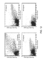
- FIG. 12 shows scatter plots of proximity-based VAD test statistics vs. phase difference-based VAD test statistics.
- FIG. 13 shows tracked minimum and maximum test statistics for proximity-based VAD test statistics.
- FIG. 14 shows tracked minimum and maximum test statistics for phase-based VAD test statistics.
- FIG. 15 shows scatter plots for normalized test statistics.
- FIG. 16 shows a set of scatter plots.
- FIG. 17 shows a set of scatter plots.
- FIG. 18 shows a table of probabilities.
- FIG. 19 shows a block diagram of task T 80 .
- FIG. 20A shows a block diagram of gain computation T 110 - 1 .
- FIG. 20B shows an overall block diagram of a suppression scheme T 110 - 2 .
- FIG. 21A shows a block diagram of a suppression scheme T 110 - 3 .
- FIG. 21B shows a block diagram of module T 120 .
- FIG. 22 shows a block diagram for task T 95 .
- FIG. 23A shows a block diagram of an implementation R 200 of array R 100 .
- FIG. 23B shows a block diagram of an implementation R 210 of array R 200 .
- FIG. 24A shows a block diagram of a multimicrophone audio sensing device D 10 according to a general configuration.
- FIG. 24B shows a block diagram of a communications device D 20 that is an implementation of device D 10 .
- FIG. 25 shows front, rear, and side views of a handset H 100 .
- FIG. 26 illustrates mounting variability in a headset D 100 .
- VAD voice activity detection
- the techniques disclosed herein may be used to improve voice activity detection (VAD) in order to enhance speech processing, such as voice coding.
- VAD techniques may be used to improve the accuracy and reliability of voice detection, and thus, to improve functions that depend on VAD, such as noise reduction, echo cancellation, rate coding and the like.
- Such improvement may be achieved, for example, by using VAD information that may be provided from one or more separate devices.
- the VAD information may be generated using multiple microphones or other sensor modalities to provide a more accurate voice activity detector.
- VAD Voice over IP
- SNR signal-to-noise-ratio
- a target voice may be identified, and such a detector may be used to provide a reliable estimation of target voice activity. It may be desirable to use VAD information to control vocoder functions, such as noise estimation update, echo cancellation (EC), rate-control, and the like.
- a more reliable and accurate VAD can be used to improve speech processing functions such as the following: noise reduction (NR) (i.e., with more reliable VAD, higher NR may be performed in non-voice segments); voice and non-voiced segment estimation; echo cancellation (EC); improved double detection schemes; and rate coding improvements which allow more aggressive rate coding schemes (for example, a lower rate for non-voice segments).
- noise reduction i.e., with more reliable VAD, higher NR may be performed in non-voice segments
- voice and non-voiced segment estimation e.e., voice and non-voiced segment estimation
- echo cancellation EC
- rate coding improvements which allow more aggressive rate coding schemes (for example, a lower rate for non-voice segments).
- the term “signal” is used herein to indicate any of its ordinary meanings, including a state of a memory location (or set of memory locations) as expressed on a wire, bus, or other transmission medium.
- the term “generating” is used herein to indicate any of its ordinary meanings, such as computing or otherwise producing.
- the term “calculating” is used herein to indicate any of its ordinary meanings, such as computing, evaluating, smoothing, and/or selecting from a plurality of values.
- the term “obtaining” is used to indicate any of its ordinary meanings, such as calculating, deriving, receiving (e.g., from an external device), and/or retrieving (e.g., from an array of storage elements).
- the term “selecting” is used to indicate any of its ordinary meanings, such as identifying, indicating, applying, and/or using at least one, and fewer than all, of a set of two or more. Where the term “comprising” is used in the present description and claims, it does not exclude other elements or operations.
- the term “based on” is used to indicate any of its ordinary meanings, including the cases (i) “derived from” (e.g., “B is a precursor of A”), (ii) “based on at least” (e.g., “A is based on at least B”) and, if appropriate in the particular context, (iii) “equal to” (e.g., “A is equal to B”).
- the term “in response to” is used to indicate any of its ordinary meanings, including “in response to at least.”
- references to a “location” of a microphone of a multi-microphone audio sensing device indicate the location of the center of an acoustically sensitive face of the microphone, unless otherwise indicated by the context.
- the term “channel” is used at times to indicate a signal path and at other times to indicate a signal carried by such a path, according to the particular context.
- the term “series” is used to indicate a sequence of two or more items.
- the term “logarithm” is used to indicate the base-ten logarithm, although extensions of such an operation to other bases are within the scope of this disclosure.
- frequency component is used to indicate one among a set of frequencies or frequency bands of a signal, such as a sample of a frequency domain representation of the signal (e.g., as produced by a fast Fourier transform) or a subband of the signal (e.g., a Bark scale or mel scale subband).
- offset is used herein as an antonym of the term “onset.”
- any disclosure of an operation of an apparatus having a particular feature is also expressly intended to disclose a method having an analogous feature (and vice versa), and any disclosure of an operation of an apparatus according to a particular configuration is also expressly intended to disclose a method according to an analogous configuration (and vice versa).
- configuration may be used in reference to a method, apparatus, and/or system as indicated by its particular context.
- method method
- process processing
- procedure and “technique”
- apparatus and “device” are also used generically and interchangeably unless otherwise indicated by the particular context.
- a method as described herein may be configured to process the captured signal as a series of segments. Typical segment lengths range from about five or ten milliseconds to about forty or fifty milliseconds, and the segments may be overlapping (e.g., with adjacent segments overlapping by 25% or 50%) or nonoverlapping. In one particular example, the signal is divided into a series of nonoverlapping segments or “frames”, each having a length of ten milliseconds.
- a segment as processed by such a method may also be a segment (i.e., a “subframe”) of a larger segment as processed by a different operation, or vice versa.
- FIGS. 1 and 2 show a block diagram of a dual-microphone noise suppression system that includes examples of some of these techniques, with the labels A-F indicating the correspondence between the signals exiting to the right of FIG. 1 and the same signals entering to the left of FIG. 2 .
- features of a configuration as described herein may include one or more (possibly all) of the following: low-frequency noise suppression (e.g., including inter-microphone subtraction and/or spatial processing); normalization of the VAD test statistics to maximize discrimination power for various holding angles and microphone gain mismatch; noise reference combination logic; residual noise suppression based on phase and proximity information in each time-frequency cell as well as frame-by-frame voice activity information; and residual noise suppression control based on one or more noise characteristics (for example, spectral flatness measure of the estimated noise).
- low-frequency noise suppression e.g., including inter-microphone subtraction and/or spatial processing
- normalization of the VAD test statistics to maximize discrimination power for various holding angles and microphone gain mismatch e.g., including inter-microphone subtraction and/or spatial processing
- normalization of the VAD test statistics to maximize discrimination power for various holding angles and microphone gain mismatch
- noise reference combination logic e.g., including inter-microphone subtraction and/or spatial processing
- residual noise suppression control
- FIGS. 1 and 2 may be implemented independently of the rest of the system (e.g., as part of another audio signal processing system).
- FIGS. 3A-3C and FIG. 4 show examples of subsets of the system that may be used independently.
- the class of spatially selective filtering operations includes directionally selective filtering operations, such as beamforming and/or blind source separation, and distance-selective filtering operations, such as operations based on source proximity. Such operations can achieve substantial noise reduction with negligible voice impairments.
- a typical example of a spatially selective filtering operation includes computing adaptive filters (e.g., based on one or more suitable voice activity detection signals) to remove desired speech to generate a noise channel and/or to remove unwanted noise by performing subtraction of a spatial noise reference and a primary microphone signal.
- FIG. 7B shows a block diagram of an example of such a scheme in which
- Removal of low-frequency noise (e.g., noise in a frequency range of 0-500 Hz) poses unique challenges.
- a fast Fourier transform FFT
- FFT fast Fourier transform
- Fourier-domain circular convolution problems may compel the use of short filters, which may hamper effective post-processing of such a signal.
- the effectiveness of a spatially selective filtering operation may also be limited in the low-frequency range by the microphone distance and in the high frequencies by spatial aliasing. For example, spatial filtering is typically largely ineffective in the range of 0-500 Hz.
- the device may be held in various orientations with respect to the user's mouth.
- the SNR may be expected to differ from one microphone to another for most handset holding angles.
- the distributed noise level may be expected to remain approximately equal from one microphone to another. Consequently, inter-microphone channel subtraction may be expected to improve SNR in the primary microphone channel.
- FIGS. 5 and 6 show an example of a stereo speech recording in car noise, where FIG. 5 shows a plot of the time-domain signal and FIG. 6 shows a plot of the frequency spectrum.
- the upper trace corresponds to the signal from the primary microphone (i.e., the microphone that is oriented toward the user's mouth or otherwise receives the user's voice most directly) and the lower trace corresponds to the signal from the secondary microphone.
- the frequency spectrum plot shows that the SNR is better in the primary microphone signal. For example, it may be seen that voiced speech peaks are higher in the primary microphone signal, while background noise valleys are about equally loud between the channels.
- Inter-microphone channel subtraction may typically be expected to result in 8-12 dB noise reduction in the [0-500 Hz] band with very little voice distortion, which is similar to the noise reduction results that may be obtained by spatial processing using large microphone arrays with many elements.
- Low-frequency noise suppression may include inter-microphone subtraction and/or spatial processing.
- One example of a method of reducing noise in a multichannel audio signal includes using an inter-microphone difference for frequencies less than 500 Hz, and using a spatially selective filtering operation (e.g., a directionally selective operation, such as a beamformer) for frequencies greater than 500 Hz.
- a spatially selective filtering operation e.g., a directionally selective operation, such as a beamformer
- an adaptive gain calibration filter may be used to avoid a gain mismatch between two microphone channels.
- Such a filter may be calculated according to a low-frequency gain difference between the signals from the primary and secondary microphones.
- a gain calibration filter M may be obtained over a speech-inactive interval according to an expression such as
- ⁇ M ⁇ ( ⁇ ) ⁇ ⁇ Y 1 ⁇ ( ⁇ ) ⁇ ⁇ Y 2 ⁇ ( ⁇ ) ⁇ , ( 1 )
- ⁇ denotes frequency
- Y 1 denotes the primary microphone channel
- Y 2 denotes the secondary microphone channel
- ⁇ denotes a vector norm operation (e.g., an L 2 -norm).
- the secondary microphone channel may be expected to contain some voice energy, such that the overall voice channel may be attenuated by a simple subtraction process. Consequently, it may be desirable to introduce a make-up gain to scale the voice gain back to its original level.
- ⁇ Y n ( ⁇ ) ⁇ G *( ⁇ Y 1 ( ⁇ ) ⁇ M ( ⁇ )* Y 2 ( ⁇ ) ⁇ ), (2) where Y n denotes the resulting output channel and G denotes an adaptive voice make-up gain factor.
- the phase may be obtained from the original primary microphone signal.
- the adaptive voice make-up gain factor G may be determined by low-frequency voice calibration over [0-500 Hz] to avoid introducing reverberation.
- Voice make-up gain G can be obtained over a speech-active interval according to an expression such as
- inter-microphone subtraction may be preferred to an adaptive filtering scheme.
- the low-frequency content e.g., in the [0-500 Hz] range
- the adaptive beamforming output Y n is overwritten with the inter-microphone subtraction module below 500 Hz.
- the adaptive null beamforming scheme also produces a noise reference, which is used in a post-processing stage.
- FIGS. 7A and 7B summarize an example of such an inter-microphone subtraction method T 50 .
- inter-microphone subtraction provides the “spatial” output Y n as shown in FIG. 3 , while an adaptive null beamformer still supplies the noise reference SPNR.
- the adaptive beamformer provides the output Y n as well as the noise reference SPNR, as shown in FIG. 7B .
- Voice activity detection is used to indicate the presence or absence of human speech in segments of an audio signal, which may also contain music, noise, or other sounds. Such discrimination of speech-active frames from speech-inactive frames is an important part of speech enhancement and speech coding, and voice activity detection is an important enabling technology for a variety of speech-based applications. For example, voice activity detection may be used to support applications such as voice coding and speech recognition. Voice activity detection may also be used to deactivate some processes during non-speech segments. Such deactivation may be used to avoid unnecessary coding and/or transmission of silent frames of the audio signal, saving on computation and network bandwidth. A method of voice activity detection (e.g., as described herein) is typically configured to iterate over each of a series of segments of an audio signal to indicate whether speech is present in the segment.
- a voice activity detection operation within a voice communications system may be able to detect voice activity in the presence of very diverse types of acoustic background noise.
- One difficulty in the detection of voice in noisy environments is the very low signal-to-noise ratios (SNRs) that are sometimes encountered. In these situations, it is often difficult to distinguish between voice and noise, music, or other sounds using known VAD techniques.
- SNRs signal-to-noise ratios
- voice activity measure also called a “test statistic” that may be calculated from an audio signal is signal energy level.
- voice activity measure is the number of zero crossings per frame (i.e., the number of times the sign of the value of the input audio signal changes from one sample to the next).
- Results of pitch estimation and detection algorithms may also be used to as voice activity measures, as well as results of algorithms that compute formants and/or cepstral coefficients to indicate the presence of voice.
- Further examples include voice activity measures based on SNR and voice activity measures based on likelihood ratio. Any suitable combination of two or more voice activity measures may also be employed.
- a voice activity measure may be based on speech onset and/or offset. It may be desirable to perform detection of speech onsets and/or offsets based on the principle that a coherent and detectable energy change occurs over multiple frequencies at the onset and offset of speech. Such an energy change may be detected, for example, by computing first-order time derivatives of energy (i.e., rate of change of energy over time) over all frequency bands, for each of a number of different frequency components (e.g., subbands or bins). In such case, a speech onset may be indicated when a large number of frequency bands show a sharp increase in energy, and a speech offset may be indicated when a large number of frequency bands show a sharp decrease in energy.
- first-order time derivatives of energy i.e., rate of change of energy over time
- a speech onset may be indicated when a large number of frequency bands show a sharp increase in energy
- a speech offset may be indicated when a large number of frequency bands show a sharp decrease in energy.
- a voice activity measure may be based on a difference between the channels.
- voice activity measures that may be calculated from a multi-channel signal (e.g., a dual-channel signal) include measures based on a magnitude difference between channels (also called gain-difference-based, level-difference-based, or proximity-based measures) and measures based on phase differences between channels.
- the test statistic used in this example is the average number of frequency bins with the estimated DoA in the range of look direction (also called a phase coherency or directional coherency measure), where DoA may be calculated as a ratio of phase difference to frequency.
- the test statistic used in this example is the log RMS level difference between the primary and the secondary microphones. Additional description of voice activity measures based on magnitude and phase differences between channels may be found in U.S. Publ. Pat. Appl. No. 2010/00323652, entitled “SYSTEMS, METHODS, APPARATUS, AND COMPUTER-READABLE MEDIA FOR PHASE-BASED PROCESSING OF MULTICHANNEL SIGNAL.”
- a magnitude-difference-based voice activity measure is a low-frequency proximity-based measure.
- a statistic may be calculated as a gain difference (e.g., log RMS level difference) between channels in a low-frequency region, such as below 1 kHz, below 900 Hz, or below 500 Hz.
- a binary voice activity decision may be obtained by applying a threshold value to the voice activity measure value (also called a score). Such a measure may be compared to a threshold value to determine voice activity. For example, voice activity may be indicated by an energy level that is above a threshold, or a number of zero crossings that is above a threshold. Voice activity may also be determined by comparing frame energy of a primary microphone channel to an average frame energy.
- VAD decision it may be desirable to combine multiple voice activity measures to obtain a VAD decision.
- VAD decision it may be desirable to combine multiple voice activity decisions using AND and/or OR logic.
- the measures to be combined may have different resolutions in time (e.g., a value for every frame vs. every other frame).
- the threshold value for one measure may be a function of a corresponding value of another measure.
- Onset and/or offset detection may also be used to vary a gain of another VAD signal, such as a magnitude-difference-based measure and/or a phase-difference-based measure.
- the VAD statistic may be multiplied by a factor greater than one or increased by a bias value greater than zero (before thresholding), in response to onset and/or offset indication.
- a phase-based VAD statistic (e.g., a coherency measure) is multiplied by a factor ph_mult>1, and a gain-based VAD statistic (e.g., a difference between channel levels) is multiplied by a factor pd_mult>1, if onset detection or offset detection is indicated for the segment.
- values for ph_mult include 2, 3, 3.5, 3.8, 4, and 4.5.
- values for pd_mult include 1.2, 1.5, 1.7, and 2.0.
- one or more such statistics may be attenuated (e.g., multiplied by a factor less than one), in response to a lack of onset and/or offset detection in the segment.
- any method of biasing the statistic in response to onset and/or offset detection state may be used (e.g., adding a positive bias value in response to detection or a negative bias value in response to lack of detection, raising or lowering a threshold value for the test statistic according to the onset and/or offset detection, and/or otherwise modifying a relation between the test statistic and the corresponding threshold).
- the final VAD decision may include results from a single-channel VAD operation (e.g., comparison of frame energy of a primary microphone channel to an average frame energy). In such case, it may be desirable to combine the decisions of the single-channel VAD operation with other VAD decisions using an OR operation. In another example, a VAD decision that is based on differences between channels is combined with the value (single-channel VAD ⁇ onset VAD ⁇ offset VAD) using an AND operation.
- a proposed module T 120 as shown in the block diagram of FIG. 21B suppresses the final output signal T 120 A when all the VADs indicate there is no speech, with appropriate smoothing T 120 B (e.g., temporal smoothing of the gain factor).
- FIG. 12 shows scatter plots of proximity-based VAD test statistics vs. phase difference-based VAD test statistics for 6 dB SNR with holding angles of ⁇ 30, ⁇ 50, ⁇ 70, and ⁇ 90 degrees from the horizontal.
- the test statistic used in this example is the average number of frequency bins with the estimated DoA in the range of look direction (e.g., within +/ ⁇ ten degrees)
- the test statistic used in this example is the log RMS level difference between the primary and the secondary microphones.
- the gray dots correspond to speech-active frames, while the black dots correspond to speech-inactive frames.
- dual-channel VADs are in general more accurate than single-channel techniques, they are typically highly dependent on the microphone gain mismatch and/or the angle at which the user is holding the phone. From FIG. 12 , it may be understood that a fixed threshold may not be suitable for different holding angles.
- One approach to dealing with a variable holding angle is to detect the holding angle (for example, using direction of arrival (DoA) estimation, which may be based on phase difference or time-difference-of-arrival (TDOA), and/or gain difference between microphones).
- DoA direction of arrival
- TDOA time-difference-of-arrival
- An approach that is based on gain differences may be sensitive to differences between the gain responses of the microphones.
- Another approach to dealing with a variable holding angle is to normalize the voice activity measures. Such an approach may be implemented to have the effect of making the VAD threshold a function of statistics that are related to the holding angle, without explicitly estimating the holding angle.
- a suitable threshold For offline processing, it may be desirable to obtain a suitable threshold by using a histogram. Specifically, by modeling the distribution of a voice activity measure as two Gaussians, a threshold value can be computed. But for real-time online processing, the histogram is typically inaccessible, and estimation of the histogram is often unreliable.
- FIG. 8A shows a conceptual diagram of such a normalization scheme.
- FIG. 8B shows a flowchart of a method M 100 of processing an audio signal according to a general configuration that includes tasks T 100 , T 200 , T 300 , and T 400 .
- task T 100 calculates a series of values of a first voice activity measure.
- task T 200 calculates a series of values of a second voice activity measure that is different from the first voice activity measure.
- task T 300 calculates a boundary value of the first voice activity measure.
- task T 400 produces a series of combined voice activity decisions.
- Task T 100 may be configured to calculate the series of values of the first voice activity measure based on a relation between channels of the audio signal.
- the first voice activity measure may be a phase-difference-based measure as described herein.
- task T 200 may be configured to calculate the series of values of the second voice activity measure based on a relation between channels of the audio signal.
- the second voice activity measure may be a magnitude-difference-based measure or a low-frequency proximity-based measure as described herein.
- task T 200 may be configured to calculate the series of values of the second voice activity measure based on detection of speech onsets and/or offsets as described herein.
- smoothing the voice activity measure such as first-order IIR smoothing.
- the minimum of the smoothed measure may
- minimum-statistics noise power spectrum estimation algorithm for minimum and maximum smoothed test-statistic tracking.
- maximum test-statistic tracking it may be desirable to use the same minimum-tracking algorithm.
- an input suitable for the algorithm may be obtained by subtracting the value of the voice activity measure from an arbitrary fixed large number. The operation may be reversed at the output of the algorithm to obtain the maximum tracked value.
- Task T 400 may be configured to compare the series of first and second voice activity measures to corresponding thresholds and to combine the resulting voice activity decisions to produce the series of combined voice activity decisions.
- Task T 400 may be configured to warp the test statistics to make a minimum smoothed statistic value of zero and a maximum smoothed statistic value of one according to an expression such as the following:
- s t ′ s t - s m ⁇ ⁇ i ⁇ ⁇ n s MAX - s m ⁇ ⁇ i ⁇ ⁇ n ⁇ ⁇ ( 5 )
- s t denotes the input test statistic
- s t ′ denotes the normalized test statistic
- s min denotes the tracked minimum smoothed test statistic
- s MAX denotes the tracked maximum smoothed test statistic
- ⁇ denotes the original (fixed) threshold. It is noted that the normalized test statistic s t ′ may have a value outside of the [0, 1] range due to the smoothing.
- FIG. 9A shows a flowchart of an implementation T 402 of task T 400 that includes tasks T 410 a , T 410 b , and T 420 .
- Task T 410 a compares each of a first set of values to a first threshold to obtain a first series of voice activity decisions
- task T 410 b compares each of a second set of values to a second threshold to obtain a second series of voice activity decisions
- task T 420 combines the first and second series of voice activity decisions to produce the series of combined voice activity decisions (e.g., according to any of the logical combination schemes described herein).
- FIG. 9B shows a flowchart of an implementation T 412 a of task T 410 a that includes tasks TA 10 and TA 20 .
- Task TA 10 obtains the first set of values by normalizing the series of values of the first voice activity measure according to the boundary value calculated by task T 300 (e.g., according to expression (5) above).
- Task TA 20 obtains the first series of voice activity decisions by comparing each of the first set of values to a threshold value.
- Task T 410 b may be similarly implemented.
- FIG. 9C shows a flowchart of an alternate implementation T 414 a of task T 410 a that includes tasks TA 30 and TA 40 .
- Task TA 30 calculates an adaptive threshold value that is based on the boundary value calculated by task T 300 (e.g., according to expression (6) above).
- Task TA 40 obtains the first series of voice activity decisions by comparing each of the series of values of the first voice activity measure to the adaptive threshold value.
- Task T 410 b may be similarly implemented.
- a phase-difference-based VAD is typically immune to differences in the gain responses of the microphones
- a magnitude-difference-based VAD is typically highly sensitive to such a mismatch.
- a potential additional benefit of this scheme is that the normalized test statistic s t ′ is independent of microphone gain calibration. Such an approach may also reduce sensitivity of a gain-based measure to microphone gain response mismatch. For example, if the gain response of the secondary microphone is 1 dB higher than normal, then the current test statistic s t , as well as the maximum statistic s MAX and the minimum statistic s min , will be 1 dB lower. Therefore, the normalized test statistic s t ′ will be the same.
- FIG. 13 shows the tracked minimum (black, lower trace) and maximum (gray, upper trace) test statistics for proximity-based VAD test statistics for 6 dB SNR with holding angles of ⁇ 30, ⁇ 50, ⁇ 70, and ⁇ 90 degrees from the horizontal.
- FIG. 14 shows the tracked minimum (black, lower trace) and maximum (gray, upper trace) test statistics for phase-based VAD test statistics for 6 B SNR with holding angles of ⁇ 30, ⁇ 50, ⁇ 70, and ⁇ 90 degrees from the horizontal.
- FIG. 15 shows scatter plots for the test statistics normalized according to equation (5).
- the two gray lines and the three black lines in each plot indicate possible suggestions for two different VAD thresholds (the right upper side of all the lines with one color is considered to be speech-active frames), which are set to be the same for all four holding angles. For convenience, these lines are shown in isolation in FIG. 11B .
- s t ′ s t - s m ⁇ ⁇ i ⁇ ⁇ n ( s MAX - s m ⁇ ⁇ i ⁇ ⁇ n ) 1 - ⁇ ⁇ ⁇ ⁇ ( 7 ) or, equivalently, s t ( s MAX ⁇ s min ) 1- ⁇ ⁇ +s min (8) where 0 ⁇ 1 is a parameter controlling a trade-off between normalizing the score and inhibiting an increase in the variance of the noise statistics. It is noted that the normalized statistic in expression (7) is also independent of microphone gain variation, since s MAX ⁇ s min will be independent of microphone gains.
- a tracked minimum value and a tracked maximum value may be used to map a series of values of a voice activity measure to the range [0, 1] (with allowance for smoothing).
- FIG. 10A illustrates such a mapping. In some cases, however, it may be desirable to track only one boundary value and to fix the other boundary.
- FIG. 10B shows an example in which the maximum value is tracked and the minimum value is fixed at zero. It may be desirable to configure task T 400 to apply such a mapping, for example, to a series of values of a phase-based voice activity measure (e.g., to avoid problems from sustained voice activity that may cause the minimum value to become too high).
- FIG. 10C shows an alternate example in which the minimum value is tracked and the maximum value is fixed at one.
- Task T 400 may also be configured to normalize a voice activity measure based on speech onset and/or offset (e.g., as in expression (5) or (7) above). Alternatively, task T 400 may be configured to adapt a threshold value corresponding to the number of frequency bands that are activated (i.e., that show a sharp increase or decrease in energy), such as according to expression (6) or (8) above.
- ⁇ E(k,n) denotes the time-derivative of energy for frequency k and frame n. It may also be desirable to track the maximum as the square of a clipped value of ⁇ E(k,n) (e.g., as the square of max[0, ⁇ E(k,n)] for onset and the square of min[0, ⁇ E(k,n)] for offset).
- FIG. 10D shows a block diagram of an apparatus A 100 according to a general configuration that includes a first calculator 100 , a second calculator 200 , a boundary value calculator 300 , and a decision module 400 .
- First calculator 100 is configured to calculate a series of values of a first voice activity measure, based on information from a first plurality of frames of the audio signal (e.g., as described herein with reference to task T 100 ).
- First calculator 100 is configured to calculate a series of values of a second voice activity measure that is different from the first voice activity measure, based on information from a second plurality of frames of the audio signal (e.g., as described herein with reference to task T 200 ).
- Boundary value calculator 300 is configured to calculate a boundary value of the first voice activity measure, based on the series of values of the first voice activity measure (e.g., as described herein with reference to task T 300 ).
- Decision module 400 is configured to produce a series of combined voice activity decisions, based on the series of values of the first voice activity measure, the series of values of the second voice activity measure, and the calculated boundary value of the first voice activity measure (e.g., as described herein with reference to task T 400 ).
- FIG. 11A shows a block diagram of an apparatus MF 100 according to another general configuration.
- Apparatus MF 100 includes means F 100 for calculating a series of values of a first voice activity measure, based on information from a first plurality of frames of the audio signal (e.g., as described herein with reference to task T 100 ).
- Apparatus MF 100 also includes means F 200 for calculating a series of values of a second voice activity measure that is different from the first voice activity measure, based on information from a second plurality of frames of the audio signal (e.g., as described herein with reference to task T 200 ).
- Apparatus MF 100 also includes means F 300 for calculating a boundary value of the first voice activity measure, based on the series of values of the first voice activity measure (e.g., as described herein with reference to task T 300 ).
- Apparatus MF 100 includes means F 400 for producing a series of combined voice activity decisions, based on the series of values of the first voice activity measure, the series of values of the second voice activity measure, and the calculated boundary value of the first voice activity measure (e.g., as described herein with reference to task T 400 ).
- a speech processing system may intelligently combine estimation of non-stationary noise and estimation of stationary noise. Such a feature may help the system to avoid introducing artifacts, such as voice attenuation and/or musical noise. Examples of logic schemes for combining noise references (e.g., for combining estimates of stationary and nonstationary noise) are described below.
- a method of reducing noise in a multichannel audio signal may include producing a combined noise estimate as a linear combination of at least one estimate of stationary noise within the multichannel signal and at least one estimate of nonstationary noise within the multichannel signal.
- the weight for each noise estimate N i [n] as W i [n]
- the combined noise reference can be expressed as a linear combination ⁇ W i [n]*N i [n] of weighted noise estimates, where ⁇ W i [n] ⁇ 1.
- the weights may be dependent on the decision between single- and dual-microphone modes, based on DoA estimation and the statistics on the input signal (e.g., normalized phase coherency measure).
- the weight for a nonstationary noise reference which is based on spatial processing may be desirable to set the weight for a nonstationary noise reference which is based on spatial processing to zero for single-microphone mode.
- the weight for a VAD-based long-term noise estimate and/or nonstationary noise estimate may be higher for speech-inactive frames where the normalized phase coherency measure is low, because such estimates tend to be more reliable for speech-inactive frames.
- At least one of said weights may be based on an estimated direction of arrival of the multichannel signal. Additionally or alternatively, it may be desirable in such a method for the linear combination to be a linear combination of weighted noise estimates, and for at least one of said weights to be based on a phase coherency measure of the multichannel signal. Additionally or alternatively, it may be desirable in such a method to nonlinearly combine the combined noise estimate with a masked version of at least one channel of the multichannel signal.
- FIG. 19 shows an exemplary block diagram of such a task T 80 .
- a conventional dual-microphone noise reference system typically includes a spatial filtering stage followed by a post-processing stage.
- Such post-processing may include a spectral subtraction operation that subtracts a noise estimate as described herein (e.g., a combined noise estimate) from noisy speech frames in the frequency domain to produce a speech signal.
- a noise estimate as described herein e.g., a combined noise estimate
- such post-processing includes a Wiener filtering operation that reduces noise in the noisy speech frames, based on a noise estimate as described herein (e.g., a combined noise estimate), to produce the speech signal.
- a residual noise suppression method may be based on proximity information (e.g., inter-microphone magnitude difference) for each time-frequency cell, based on phase difference for each time-frequency cell, and/or based on frame-by-frame VAD information.
- proximity information e.g., inter-microphone magnitude difference
- a residual noise suppression based on magnitude difference between two microphones may include a gain function based on the threshold and TF gain difference.
- Such a method is related to time-frequency (TF) gain-difference-based VAD, although it utilizes a soft decision rather than a hard decision.
- FIG. 20A shows a block diagram of this gain computation T 110 - 1 .
- It may be desirable to perform a method of reducing noise in a multichannel audio signal that includes calculating a plurality of gain factors, each based on a difference between two channels of the multichannel signal in a corresponding frequency component; and applying each of the calculated gain factors to the corresponding frequency component of at least one channel of the multichannel signal.
- Such a method may also include normalizing at least one of the gain factors based on a minimum value of the gain factor over time. Such normalizing may be based on a maximum value of the gain factor over time.
- each of the gain factors may be based on a power ratio between two channels of the multichannel signal in a corresponding frequency component during noisy speech.
- Such a method may include varying the look direction according to a voice-activity-detection signal.
- test statistic for TF proximity VAD in this example is the ratio between the magnitudes of two microphone signals in that TF cell. This statistic may then be normalized using the tracked maximum and minimum value of the magnitude ratio (e.g., as shown in equation (5) or (7) above).
- the global maximum and minimum of log RMS level difference between two microphone signals can be used with an offset parameter whose value is dependent on frequency, frame-by-frame VAD decision, and/or holding angle.
- the frame-by-frame VAD decision it may be desirable to use a higher value of the offset parameter for speech-active frames for a more robust decision. In this way, the information in other frequencies can be utilized.
- s MAX ⁇ s min of the proximity VAD in equation (7) as a representation of the holding angle. Since the high-frequency component of speech is likely to be attenuated more for an optimal holding angle (e.g., ⁇ 30 degrees from the horizontal) as compared with the low-frequency component, it may be desirable to change the spectral tilt of the offset parameter or threshold according to the holding angle.
- TF proximity VAD can be decided by comparing it with the threshold ⁇ .
- G[k] 10 ⁇ ( ⁇ ′ ⁇ s t′′ ) with maximum (1.0) and minimum gain limitation, where ⁇ ′ is typically set to be higher than the hard-decision VAD threshold ⁇ .
- the tuning parameter ⁇ may be used to control the gain function roll-off, with a value that may depend on the scaling adopted for the test statistic and threshold.
- a residual noise suppression based on magnitude difference between two microphones may include a gain function based on the TF gain difference for input signal and that of clean speech. While a gain function based on the threshold and TF gain difference as described in the previous section has its rational, the resulting gain may not be optimal in any sense.
- the clean speech signal DFT coefficient in the primary microphone signal and in the secondary microphone signal is X 1 [k] and X 2 [k], respectively, where k is a frequency bin index.
- the test statistic for TF proximity VAD is 20 log
- this test statistic is almost constant for each frequency bin.
- this statistic is 10 log f[k], where f[k] may be computed from the clean speech data.
- the value of parameter f[k] is likely to depend on the holding angle. Also, it may be desirable to use the minimum value of the proximity VAD test statistic to adjust g[k] (e.g., to cope with the microphone gain calibration mismatch). Also, it may be desirable to limit the gain G[k] to be higher than a certain minimum value which may be dependent on band SNR, frequency, and/or noise statistic. Note that this gain G[k] should be wisely combined with other processing gains, such as spatial filtering and post-processing.
- FIG. 20B shows an overall block diagram of such a suppression scheme T 110 - 2 .
- a residual noise suppression scheme may be based on time-frequency phase-based VAD.
- Time-frequency phase VAD is calculated from the direction of arrival (DoA) estimation for each TF cell, along with the frame-by-frame VAD information and holding angle.
- DoA is estimated from the phase difference between two microphone signals in that band. If the observed phase difference indicates that the cos(DoA) value is out of [ ⁇ 1, 1] range, it is considered to be a missing observation. In this case, it may be desirable for the decision in that TF cell to follow the frame-by-frame VAD. Otherwise, the estimated DoA is examined if it is in the look direction range, and an appropriate gain is applied according to a relation (e.g., a comparison) between the look direction range and the estimated DoA.
- a relation e.g., a comparison
- FIG. 21A shows a block diagram of such a suppression scheme T 110 - 3 .
- a proposed module T 120 as shown in the block diagram of FIG. 21B suppresses the final output signal when all the VADs indicate there is no speech, with appropriate smoothing (e.g., temporal smoothing of the gain factor).
- noise suppression techniques may have advantages for different types of noises. For example, spatial filtering is fairly good for competing talker noise, while the typical single-channel noise suppression is strong for stationary noise, especially white or pink noise. One size does not fit all, however. Tuning for competing talker noise, for example, is likely to result in modulated residual noise when the noise has a flat spectrum.
- One example of such a noise characteristic is a measure of the spectral flatness of the estimated noise. Such a measure may be used to control one or more tuning parameters, such as the aggressiveness of each noise suppression module in each frequency component (i.e., subband or bin).
- V( ⁇ ) is the normalized log spectrum. Since V( ⁇ ) is the normalized log spectrum, this expression is equivalent to
- ⁇ ⁇ - ⁇ ⁇ ⁇ ⁇ - V ⁇ ( ⁇ ) ⁇ ⁇ d ⁇ 2 ⁇ ⁇ , which is just the mean of the normalized log spectrum in the DFT domain and may be calculated as such. It may also be desirable to smooth the spectral flatness measure over time.
- the smoothed spectral flatness measure may be used to control SNR-dependent aggressiveness function of the residual noise suppression and comb filtering. Other types of noise spectrum characteristics can be also used to control the noise suppression behavior.
- FIG. 22 shows a block diagram for a task T 95 that is configured to indicate spectral flatness by thresholding the spectral flatness measure.
- the VAD strategies described herein may be implemented using one or more portable audio sensing devices that each has an array R 100 of two or more microphones configured to receive acoustic signals.
- portable audio sensing device that may be constructed to include such an array and to be used with such a VAD strategy for audio recording and/or voice communications applications include a telephone handset (e.g., a cellular telephone handset); a wired or wireless headset (e.g., a Bluetooth headset); a handheld audio and/or video recorder; a personal media player configured to record audio and/or video content; a personal digital assistant (PDA) or other handheld computing device; and a notebook computer, laptop computer, netbook computer, tablet computer, or other portable computing device.
- PDA personal digital assistant
- Other examples of audio sensing devices that may be constructed to include instances of array R 100 and to be used with such a VAD strategy include set-top boxes and audio- and/or video-conferencing devices.
- Each microphone of array R 100 may have a response that is omnidirectional, bidirectional, or unidirectional (e.g., cardioid).
- the various types of microphones that may be used in array R 100 include (without limitation) piezoelectric microphones, dynamic microphones, and electret microphones.
- the center-to-center spacing between adjacent microphones of array R 100 is typically in the range of from about 1.5 cm to about 4.5 cm, although a larger spacing (e.g., up to 10 or 15 cm) is also possible in a device such as a handset or smartphone, and even larger spacings (e.g., up to 20, 25 or 30 cm or more) are possible in a device such as a tablet computer.
- the center-to-center spacing between adjacent microphones of array R 100 may be as little as about 4 or 5 mm.
- the microphones of array R 100 may be arranged along a line or, alternatively, such that their centers lie at the vertices of a two-dimensional (e.g., triangular) or three-dimensional shape. In general, however, the microphones of array R 100 may be disposed in any configuration deemed suitable for the particular application.
- array R 100 produces a multichannel signal in which each channel is based on the response of a corresponding one of the microphones to the acoustic environment.
- One microphone may receive a particular sound more directly than another microphone, such that the corresponding channels differ from one another to provide collectively a more complete representation of the acoustic environment than can be captured using a single microphone.
- FIG. 23A shows a block diagram of an implementation R 200 of array R 100 that includes an audio preprocessing stage AP 10 configured to perform one or more such operations, which may include (without limitation) impedance matching, analog-to-digital conversion, gain control, and/or filtering in the analog and/or digital domains.
- FIG. 23B shows a block diagram of an implementation R 210 of array R 200 .
- Array R 210 includes an implementation AP 20 of audio preprocessing stage AP 10 that includes analog preprocessing stages P 10 a and P 10 b .
- stages P 10 a and P 10 b are each configured to perform a highpass filtering operation (e.g., with a cutoff frequency of 50, 100, or 200 Hz) on the corresponding microphone signal.
- array R 100 may be desirable for array R 100 to produce the multichannel signal as a digital signal, that is to say, as a sequence of samples.
- Array R 210 includes analog-to-digital converters (ADCs) C 10 a and C 10 b that are each arranged to sample the corresponding analog channel.
- ADCs analog-to-digital converters
- Typical sampling rates for acoustic applications include 8 kHz, 12 kHz, 16 kHz, and other frequencies in the range of from about 8 to about 16 kHz, although sampling rates as high as about 44.1, 48, and 192 kHz may also be used.
- array R 210 also includes digital preprocessing stages P 20 a and P 20 b that are each configured to perform one or more preprocessing operations (e.g., echo cancellation, noise reduction, and/or spectral shaping) on the corresponding digitized channel to produce the corresponding channels MCS- 1 , MCS- 2 of multichannel signal MCS.
- digital preprocessing stages P 20 a and P 20 b may be implemented to perform a frequency transform (e.g., an FFT or MDCT operation) on the corresponding digitized channel to produce the corresponding channels MCS 10 - 1 , MCS 10 - 2 of multichannel signal MCS 10 in the corresponding frequency domain.
- 23A and 23B show two-channel implementations, it will be understood that the same principles may be extended to an arbitrary number of microphones and corresponding channels of multichannel signal MCS 10 (e.g., a three-, four-, or five-channel implementation of array R 100 as described herein).
- the microphones may be implemented more generally as transducers sensitive to radiations or emissions other than sound.
- the microphone pair is implemented as a pair of ultrasonic transducers (e.g., transducers sensitive to acoustic frequencies greater than fifteen, twenty, twenty-five, thirty, forty, or fifty kilohertz or more).
- FIG. 24A shows a block diagram of a multimicrophone audio sensing device D 10 according to a general configuration.
- Device D 10 includes an instance of microphone array R 100 and an instance of any of the implementations of apparatus A 100 (or MF 100 ) disclosed herein, and any of the audio sensing devices disclosed herein may be implemented as an instance of device D 10 .
- Device D 10 also includes an apparatus A 100 that is configured to process the multichannel audio signal MCS by performing an implementation of a method as disclosed herein.
- Apparatus A 100 may be implemented as a combination of hardware (e.g., a processor) with software and/or with firmware.
- FIG. 24B shows a block diagram of a communications device D 20 that is an implementation of device D 10 .
- Device D 20 includes a chip or chipset CS 10 (e.g., a mobile station modem (MSM) chipset) that includes an implementation of apparatus A 100 (or MF 100 ) as described herein.
- Chip/chipset CS 10 may include one or more processors, which may be configured to execute all or part of the operations of apparatus A 100 or MF 100 (e.g., as instructions).
- Chip/chipset CS 10 may also include processing elements of array R 100 (e.g., elements of audio preprocessing stage AP 10 as described below).
- Chip/chipset CS 10 includes a receiver which is configured to receive a radio-frequency (RF) communications signal (e.g., via antenna C 40 ) and to decode and reproduce (e.g., via loudspeaker SP 10 ) an audio signal encoded within the RF signal.
- Chip/chipset CS 10 also includes a transmitter which is configured to encode an audio signal that is based on an output signal produced by apparatus A 100 and to transmit an RF communications signal (e.g., via antenna C 40 ) that describes the encoded audio signal.
- RF communications signal e.g., via antenna C 40
- one or more processors of chip/chipset CS 10 may be configured to perform a noise reduction operation as described above on one or more channels of the multichannel signal such that the encoded audio signal is based on the noise-reduced signal.
- device D 20 also includes a keypad C 10 and display C 20 to support user control and interaction.
- FIG. 25 shows front, rear, and side views of a handset H 100 (e.g., a smartphone) that may be implemented as an instance of device D 20 .
- Handset H 100 includes three microphones MF 10 , MF 20 , and MF 30 arranged on the front face; and two microphone MR 10 and MR 20 and a camera lens L 10 arranged on the rear face.
- a loudspeaker LS 10 is arranged in the top center of the front face near microphone MF 10 , and two other loudspeakers LS 20 L, LS 20 R are also provided (e.g., for speakerphone applications).
- a maximum distance between the microphones of such a handset is typically about ten or twelve centimeters.
- the methods and apparatus disclosed herein may be applied generally in any transceiving and/or audio sensing application, including mobile or otherwise portable instances of such applications and/or sensing of signal components from far-field sources.
- the range of configurations disclosed herein includes communications devices that reside in a wireless telephony communication system configured to employ a code-division multiple-access (CDMA) over-the-air interface.
- CDMA code-division multiple-access
- VoIP Voice over IP
- wired and/or wireless e.g., CDMA, TDMA, FDMA, and/or TD-SCDMA
- communications devices disclosed herein may be adapted for use in networks that are packet-switched (for example, wired and/or wireless networks arranged to carry audio transmissions according to protocols such as VoIP) and/or circuit-switched. It is also expressly contemplated and hereby disclosed that communications devices disclosed herein may be adapted for use in narrowband coding systems (e.g., systems that encode an audio frequency range of about four or five kilohertz) and/or for use in wideband coding systems (e.g., systems that encode audio frequencies greater than five kilohertz), including whole-band wideband coding systems and split-band wideband coding systems.
- narrowband coding systems e.g., systems that encode an audio frequency range of about four or five kilohertz
- wideband coding systems e.g., systems that encode audio frequencies greater than five kilohertz
- Important design requirements for implementation of a configuration as disclosed herein may include minimizing processing delay and/or computational complexity (typically measured in millions of instructions per second or MIPS), especially for computation-intensive applications, such as playback of compressed audio or audiovisual information (e.g., a file or stream encoded according to a compression format, such as one of the examples identified herein) or applications for wideband communications (e.g., voice communications at sampling rates higher than eight kilohertz, such as 12, 16, 44.1, 48, or 192 kHz).
- MIPS processing delay and/or computational complexity
- Goals of a multi-microphone processing system may include achieving ten to twelve dB in overall noise reduction, preserving voice level and color during movement of a desired speaker, obtaining a perception that the noise has been moved into the background instead of an aggressive noise removal, dereverberation of speech, and/or enabling the option of post-processing for more aggressive noise reduction.
- An apparatus as disclosed herein may be implemented in any combination of hardware with software, and/or with firmware, that is deemed suitable for the intended application.
- the elements of such an apparatus may be fabricated as electronic and/or optical devices residing, for example, on the same chip or among two or more chips in a chipset.
- One example of such a device is a fixed or programmable array of logic elements, such as transistors or logic gates, and any of these elements may be implemented as one or more such arrays. Any two or more, or even all, of the elements of the apparatus may be implemented within the same array or arrays.
- Such an array or arrays may be implemented within one or more chips (for example, within a chipset including two or more chips).
- One or more elements of the various implementations of the apparatus disclosed herein may also be implemented in whole or in part as one or more sets of instructions arranged to execute on one or more fixed or programmable arrays of logic elements, such as microprocessors, embedded processors, IP cores, digital signal processors, FPGAs (field-programmable gate arrays), ASSPs (application-specific standard products), and ASICs (application-specific integrated circuits).
- Any of the various elements of an implementation of an apparatus as disclosed herein may also be embodied as one or more computers (e.g., machines including one or more arrays programmed to execute one or more sets or sequences of instructions, also called “processors”), and any two or more, or even all, of these elements may be implemented within the same such computer or computers.
- a processor or other means for processing as disclosed herein may be fabricated as one or more electronic and/or optical devices residing, for example, on the same chip or among two or more chips in a chipset.
- a fixed or programmable array of logic elements such as transistors or logic gates, and any of these elements may be implemented as one or more such arrays.
- Such an array or arrays may be implemented within one or more chips (for example, within a chipset including two or more chips). Examples of such arrays include fixed or programmable arrays of logic elements, such as microprocessors, embedded processors, IP cores, DSPs, FPGAs, ASSPs, and ASICs.
- a processor or other means for processing as disclosed herein may also be embodied as one or more computers (e.g., machines including one or more arrays programmed to execute one or more sets or sequences of instructions) or other processors. It is possible for a processor as described herein to be used to perform tasks or execute other sets of instructions that are not directly related to a voice activity detection procedure as described herein, such as a task relating to another operation of a device or system in which the processor is embedded (e.g., an audio sensing device). It is also possible for part of a method as disclosed herein to be performed by a processor of the audio sensing device and for another part of the method to be performed under the control of one or more other processors.
- modules, logical blocks, circuits, and tests and other operations described in connection with the configurations disclosed herein may be implemented as electronic hardware, computer software, or combinations of both. Such modules, logical blocks, circuits, and operations may be implemented or performed with a general-purpose processor, a digital signal processor (DSP), an ASIC or ASSP, an FPGA or other programmable logic device, discrete gate or transistor logic, discrete hardware components, or any combination thereof designed to produce the configuration as disclosed herein.
- DSP digital signal processor
- such a configuration may be implemented at least in part as a hard-wired circuit, as a circuit configuration fabricated into an application-specific integrated circuit, or as a firmware program loaded into non-volatile storage or a software program loaded from or into a data storage medium as machine-readable code, such code being instructions executable by an array of logic elements such as a general purpose processor or other digital signal processing unit.
- a general-purpose processor may be a microprocessor, but in the alternative, the processor may be any conventional processor, controller, microcontroller, or state machine.
- a processor may also be implemented as a combination of computing devices, e.g., a combination of a DSP and a microprocessor, a plurality of microprocessors, one or more microprocessors in conjunction with a DSP core, or any other such configuration.
- a software module may reside in RAM (random-access memory), ROM (read-only memory), nonvolatile RAM (NVRAM) such as flash RAM, erasable programmable ROM (EPROM), electrically erasable programmable ROM (EEPROM), registers, hard disk, a removable disk, a CD-ROM, or any other form of storage medium known in the art.
- An illustrative storage medium is coupled to the processor such the processor can read information from, and write information to, the storage medium.
- the storage medium may be integral to the processor.
- the processor and the storage medium may reside in an ASIC.
- the ASIC may reside in a user terminal.
- the processor and the storage medium may reside as discrete components in a user terminal.
- module or “sub-module” can refer to any method, apparatus, device, unit or computer-readable data storage medium that includes computer instructions (e.g., logical expressions) in software, hardware or firmware form. It is to be understood that multiple modules or systems can be combined into one module or system and one module or system can be separated into multiple modules or systems to perform the same functions.
- the elements of a process are essentially the code segments to perform the related tasks, such as with routines, programs, objects, components, data structures, and the like.
- the term “software” should be understood to include source code, assembly language code, machine code, binary code, firmware, macrocode, microcode, any one or more sets or sequences of instructions executable by an array of logic elements, and any combination of such examples.
- the program or code segments can be stored in a processor-readable storage medium or transmitted by a computer data signal embodied in a carrier wave over a transmission medium or communication link.
- implementations of methods, schemes, and techniques disclosed herein may also be tangibly embodied (for example, in one or more computer-readable media as listed herein) as one or more sets of instructions readable and/or executable by a machine including an array of logic elements (e.g., a processor, microprocessor, microcontroller, or other finite state machine).
- a machine including an array of logic elements (e.g., a processor, microprocessor, microcontroller, or other finite state machine).
- the term “computer-readable medium” may include any medium that can store or transfer information, including volatile, nonvolatile, removable and non-removable media.
- Examples of a computer-readable medium include an electronic circuit, a semiconductor memory device, a ROM, a flash memory, an erasable ROM (EROM), a floppy diskette or other magnetic storage, a CD-ROM/DVD or other optical storage, a hard disk, a fiber optic medium, a radio frequency (RF) link, or any other medium which can be used to store the desired information and which can be accessed.
- the computer data signal may include any signal that can propagate over a transmission medium such as electronic network channels, optical fibers, air, electromagnetic, RF links, etc.
- the code segments may be downloaded via computer networks such as the Internet or an intranet. In any case, the scope of the present disclosure should not be construed as limited by such embodiments.
- Each of the tasks of the methods described herein may be embodied directly in hardware, in a software module executed by a processor, or in a combination of the two.
- an array of logic elements e.g., logic gates
- an array of logic elements is configured to perform one, more than one, or even all of the various tasks of the method.
- One or more (possibly all) of the tasks may also be implemented as code (e.g., one or more sets of instructions), embodied in a computer program product (e.g., one or more data storage media such as disks, flash or other nonvolatile memory cards, semiconductor memory chips, etc.), that is readable and/or executable by a machine (e.g., a computer) including an array of logic elements (e.g., a processor, microprocessor, microcontroller, or other finite state machine).
- the tasks of an implementation of a method as disclosed herein may also be performed by more than one such array or machine.
- the tasks may be performed within a device for wireless communications such as a cellular telephone or other device having such communications capability.
- Such a device may be configured to communicate with circuit-switched and/or packet-switched networks (e.g., using one or more protocols such as VoIP).
- a device may include RF circuitry configured to receive and/or transmit encoded frames.
- a portable communications device such as a handset, headset, or portable digital assistant (PDA)
- PDA portable digital assistant
- a typical real-time (e.g., online) application is a telephone conversation conducted using such a mobile device.
- computer-readable media includes both computer-readable storage media and communication (e.g., transmission) media.
- computer-readable storage media can comprise an array of storage elements, such as semiconductor memory (which may include without limitation dynamic or static RAM, ROM, EEPROM, and/or flash RAM), or ferroelectric, magnetoresistive, ovonic, polymeric, or phase-change memory; CD-ROM or other optical disk storage; and/or magnetic disk storage or other magnetic storage devices.
- Such storage media may store information in the form of instructions or data structures that can be accessed by a computer.
- Communication media can comprise any medium that can be used to carry desired program code in the form of instructions or data structures and that can be accessed by a computer, including any medium that facilitates transfer of a computer program from one place to another.
- any connection is properly termed a computer-readable medium.
- the software is transmitted from a website, server, or other remote source using a coaxial cable, fiber optic cable, twisted pair, digital subscriber line (DSL), or wireless technology such as infrared, radio, and/or microwave
- the coaxial cable, fiber optic cable, twisted pair, DSL, or wireless technology such as infrared, radio, and/or microwave are included in the definition of medium.
- Disk and disc includes compact disc (CD), laser disc, optical disc, digital versatile disc (DVD), floppy disk and Blu-ray DiscTM (Blu-Ray Disc Association, Universal City, Calif.), where disks usually reproduce data magnetically, while discs reproduce data optically with lasers. Combinations of the above should also be included within the scope of computer-readable media.
- An acoustic signal processing apparatus as described herein may be incorporated into an electronic device that accepts speech input in order to control certain operations, or may otherwise benefit from separation of desired noises from background noises, such as communications devices.
- Many applications may benefit from enhancing or separating clear desired sound from background sounds originating from multiple directions.
- Such applications may include human-machine interfaces in electronic or computing devices which incorporate capabilities such as voice recognition and detection, speech enhancement and separation, voice-activated control, and the like. It may be desirable to implement such an acoustic signal processing apparatus to be suitable in devices that only provide limited processing capabilities.
- the elements of the various implementations of the modules, elements, and devices described herein may be fabricated as electronic and/or optical devices residing, for example, on the same chip or among two or more chips in a chipset.
- One example of such a device is a fixed or programmable array of logic elements, such as transistors or gates.
- One or more elements of the various implementations of the apparatus described herein may also be implemented in whole or in part as one or more sets of instructions arranged to execute on one or more fixed or programmable arrays of logic elements such as microprocessors, embedded processors, IP cores, digital signal processors, FPGAs, ASSPs, and ASICs.
- one or more elements of an implementation of an apparatus as described herein can be used to perform tasks or execute other sets of instructions that are not directly related to an operation of the apparatus, such as a task relating to another operation of a device or system in which the apparatus is embedded. It is also possible for one or more elements of an implementation of such an apparatus to have structure in common (e.g., a processor used to execute portions of code corresponding to different elements at different times, a set of instructions executed to perform tasks corresponding to different elements at different times, or an arrangement of electronic and/or optical devices performing operations for different elements at different times).
Abstract
Description
where ω denotes frequency, Y1 denotes the primary microphone channel, Y2 denotes the secondary microphone channel, and ∥·∥ denotes a vector norm operation (e.g., an L2-norm).
∥Y n(ω)∥=G*(∥Y 1(ω)∥−∥M(ω)*Y 2(ω)∥), (2)
where Yn denotes the resulting output channel and G denotes an adaptive voice make-up gain factor. The phase may be obtained from the original primary microphone signal.
where st denotes the input test statistic, st′ denotes the normalized test statistic, smin denotes the tracked minimum smoothed test statistic, sMAX denotes the tracked maximum smoothed test statistic, and ξ denotes the original (fixed) threshold. It is noted that the normalized test statistic st′ may have a value outside of the [0, 1] range due to the smoothing.
s t
where (sMAX−smin)ξ+smin denotes an adaptive threshold ξ□ that is equivalent to using a fixed threshold ξ with the normalized test statistic st′.
or, equivalently,
s t
where 0≦α≦1 is a parameter controlling a trade-off between normalizing the score and inhibiting an increase in the variance of the noise statistics. It is noted that the normalized statistic in expression (7) is also independent of microphone gain variation, since sMAX−smin will be independent of microphone gains.
NR TF [n,k]=(1−TF — VAD[n,k])*s[n,k],
where s denotes the input signal, n denotes a time (e.g., frame) index, and k denotes a frequency (e.g., bin or subband) index. That is, if time frequency VAD is 1 for that time-frequency cell [n,k], the TF mask noise reference for the cell is 0; otherwise, it is the TF mask noise reference for the cell is the input cell itself. It may be desirable for such a TF mask noise reference to be combined with the other noise references through a maximum operation T80C rather than a linear combination.
G[k]=10−β(ξ′−s
with maximum (1.0) and minimum gain limitation, where ξ′ is typically set to be higher than the hard-decision VAD threshold ξ. The tuning parameter β may be used to control the gain function roll-off, with a value that may depend on the scaling adopted for the test statistic and threshold.
where in practice the value of g[k] is limited to be higher than or equal to 1.0 and lower than or equal to f[k]. Then the gain applied to the primary microphone signal becomes
and V(θ) is the normalized log spectrum. Since V(θ) is the normalized log spectrum, this expression is equivalent to
which is just the mean of the normalized log spectrum in the DFT domain and may be calculated as such. It may also be desirable to smooth the spectral flatness measure over time.
Claims (50)
Priority Applications (6)
| Application Number | Priority Date | Filing Date | Title |
|---|---|---|---|
| US13/280,192 US8898058B2 (en) | 2010-10-25 | 2011-10-24 | Systems, methods, and apparatus for voice activity detection |
| PCT/US2011/057715 WO2012061145A1 (en) | 2010-10-25 | 2011-10-25 | Systems, methods, and apparatus for voice activity detection |
| KR1020137013013A KR101532153B1 (en) | 2010-10-25 | 2011-10-25 | Systems, methods, and apparatus for voice activity detection |
| CN201180051496.XA CN103180900B (en) | 2010-10-25 | 2011-10-25 | For system, the method and apparatus of voice activity detection |
| JP2013536731A JP5727025B2 (en) | 2010-10-25 | 2011-10-25 | System, method and apparatus for voice activity detection |
| EP11784837.4A EP2633519B1 (en) | 2010-10-25 | 2011-10-25 | Method and apparatus for voice activity detection |
Applications Claiming Priority (3)
| Application Number | Priority Date | Filing Date | Title |
|---|---|---|---|
| US40638210P | 2010-10-25 | 2010-10-25 | |
| US13/092,502 US9165567B2 (en) | 2010-04-22 | 2011-04-22 | Systems, methods, and apparatus for speech feature detection |
| US13/280,192 US8898058B2 (en) | 2010-10-25 | 2011-10-24 | Systems, methods, and apparatus for voice activity detection |
Related Parent Applications (1)
| Application Number | Title | Priority Date | Filing Date |
|---|---|---|---|
| US13/092,502 Continuation-In-Part US9165567B2 (en) | 2010-04-22 | 2011-04-22 | Systems, methods, and apparatus for speech feature detection |
Publications (2)
| Publication Number | Publication Date |
|---|---|
| US20120130713A1 US20120130713A1 (en) | 2012-05-24 |
| US8898058B2 true US8898058B2 (en) | 2014-11-25 |
Family
ID=44993886
Family Applications (1)
| Application Number | Title | Priority Date | Filing Date |
|---|---|---|---|
| US13/280,192 Active 2032-10-20 US8898058B2 (en) | 2010-10-25 | 2011-10-24 | Systems, methods, and apparatus for voice activity detection |
Country Status (6)
| Country | Link |
|---|---|
| US (1) | US8898058B2 (en) |
| EP (1) | EP2633519B1 (en) |
| JP (1) | JP5727025B2 (en) |
| KR (1) | KR101532153B1 (en) |
| CN (1) | CN103180900B (en) |
| WO (1) | WO2012061145A1 (en) |
Cited By (8)
| Publication number | Priority date | Publication date | Assignee | Title |
|---|---|---|---|---|
| US20130282372A1 (en) * | 2012-04-23 | 2013-10-24 | Qualcomm Incorporated | Systems and methods for audio signal processing |
| US20160321257A1 (en) * | 2015-05-01 | 2016-11-03 | Morpho Detection, Llc | Systems and methods for analyzing time series data based on event transitions |
| US20160379614A1 (en) * | 2015-06-26 | 2016-12-29 | Fujitsu Limited | Noise suppression device and method of noise suppression |
| US10304478B2 (en) * | 2014-03-12 | 2019-05-28 | Huawei Technologies Co., Ltd. | Method for detecting audio signal and apparatus |
| US11138334B1 (en) * | 2018-10-17 | 2021-10-05 | Medallia, Inc. | Use of ASR confidence to improve reliability of automatic audio redaction |
| US11425258B2 (en) * | 2020-01-06 | 2022-08-23 | Waves Audio Ltd. | Audio conferencing in a room |
| US20220358948A1 (en) * | 2021-05-05 | 2022-11-10 | Waves Audio Ltd. | Self-activated speech enhancement |
| US20230007393A1 (en) * | 2021-06-30 | 2023-01-05 | Beijing Xiaomi Mobile Software Co., Ltd. | Sound processing method, electronic device and storage medium |
Families Citing this family (48)
| Publication number | Priority date | Publication date | Assignee | Title |
|---|---|---|---|---|
| JP5575977B2 (en) | 2010-04-22 | 2014-08-20 | クゥアルコム・インコーポレイテッド | Voice activity detection |
| WO2012083552A1 (en) * | 2010-12-24 | 2012-06-28 | Huawei Technologies Co., Ltd. | Method and apparatus for voice activity detection |
| KR20120080409A (en) * | 2011-01-07 | 2012-07-17 | 삼성전자주식회사 | Apparatus and method for estimating noise level by noise section discrimination |
| PL2737479T3 (en) * | 2011-07-29 | 2017-07-31 | Dts Llc | Adaptive voice intelligibility enhancement |
| US9031259B2 (en) * | 2011-09-15 | 2015-05-12 | JVC Kenwood Corporation | Noise reduction apparatus, audio input apparatus, wireless communication apparatus, and noise reduction method |
| JP6267860B2 (en) * | 2011-11-28 | 2018-01-24 | 三星電子株式会社Samsung Electronics Co.,Ltd. | Audio signal transmitting apparatus, audio signal receiving apparatus and method thereof |
| US9384759B2 (en) * | 2012-03-05 | 2016-07-05 | Malaspina Labs (Barbados) Inc. | Voice activity detection and pitch estimation |
| US9354295B2 (en) | 2012-04-13 | 2016-05-31 | Qualcomm Incorporated | Systems, methods, and apparatus for estimating direction of arrival |
| US9305570B2 (en) | 2012-06-13 | 2016-04-05 | Qualcomm Incorporated | Systems, methods, apparatus, and computer-readable media for pitch trajectory analysis |
| CN105122359B (en) | 2013-04-10 | 2019-04-23 | 杜比实验室特许公司 | The method, apparatus and system of speech dereverbcration |
| US20140337021A1 (en) * | 2013-05-10 | 2014-11-13 | Qualcomm Incorporated | Systems and methods for noise characteristic dependent speech enhancement |
| CN104424956B9 (en) * | 2013-08-30 | 2022-11-25 | 中兴通讯股份有限公司 | Activation tone detection method and device |
| WO2015032009A1 (en) * | 2013-09-09 | 2015-03-12 | Recabal Guiraldes Pablo | Small system and method for decoding audio signals into binaural audio signals |
| JP6156012B2 (en) * | 2013-09-20 | 2017-07-05 | 富士通株式会社 | Voice processing apparatus and computer program for voice processing |
| EP2876900A1 (en) * | 2013-11-25 | 2015-05-27 | Oticon A/S | Spatial filter bank for hearing system |
| US9524735B2 (en) * | 2014-01-31 | 2016-12-20 | Apple Inc. | Threshold adaptation in two-channel noise estimation and voice activity detection |
| CN104934032B (en) * | 2014-03-17 | 2019-04-05 | 华为技术有限公司 | The method and apparatus that voice signal is handled according to frequency domain energy |
| US9467779B2 (en) | 2014-05-13 | 2016-10-11 | Apple Inc. | Microphone partial occlusion detector |
| CN105321528B (en) * | 2014-06-27 | 2019-11-05 | 中兴通讯股份有限公司 | A kind of Microphone Array Speech detection method and device |
| CN105336344B (en) * | 2014-07-10 | 2019-08-20 | 华为技术有限公司 | Noise detection method and device |
| US9953661B2 (en) * | 2014-09-26 | 2018-04-24 | Cirrus Logic Inc. | Neural network voice activity detection employing running range normalization |
| US10127919B2 (en) * | 2014-11-12 | 2018-11-13 | Cirrus Logic, Inc. | Determining noise and sound power level differences between primary and reference channels |
| MX363414B (en) * | 2014-12-12 | 2019-03-22 | Huawei Tech Co Ltd | A signal processing apparatus for enhancing a voice component within a multi-channel audio signal. |
| US9685156B2 (en) | 2015-03-12 | 2017-06-20 | Sony Mobile Communications Inc. | Low-power voice command detector |
| JP6501259B2 (en) * | 2015-08-04 | 2019-04-17 | 本田技研工業株式会社 | Speech processing apparatus and speech processing method |
| US10242689B2 (en) * | 2015-09-17 | 2019-03-26 | Intel IP Corporation | Position-robust multiple microphone noise estimation techniques |
| US9959887B2 (en) * | 2016-03-08 | 2018-05-01 | International Business Machines Corporation | Multi-pass speech activity detection strategy to improve automatic speech recognition |
| WO2017202680A1 (en) * | 2016-05-26 | 2017-11-30 | Telefonaktiebolaget Lm Ericsson (Publ) | Method and apparatus for voice or sound activity detection for spatial audio |
| US10482899B2 (en) | 2016-08-01 | 2019-11-19 | Apple Inc. | Coordination of beamformers for noise estimation and noise suppression |
| JP6677136B2 (en) | 2016-09-16 | 2020-04-08 | 富士通株式会社 | Audio signal processing program, audio signal processing method and audio signal processing device |
| EP3300078B1 (en) * | 2016-09-26 | 2020-12-30 | Oticon A/s | A voice activitity detection unit and a hearing device comprising a voice activity detection unit |
| US10720165B2 (en) * | 2017-01-23 | 2020-07-21 | Qualcomm Incorporated | Keyword voice authentication |
| US10564925B2 (en) * | 2017-02-07 | 2020-02-18 | Avnera Corporation | User voice activity detection methods, devices, assemblies, and components |
| GB2561408A (en) * | 2017-04-10 | 2018-10-17 | Cirrus Logic Int Semiconductor Ltd | Flexible voice capture front-end for headsets |
| US11854566B2 (en) | 2018-06-21 | 2023-12-26 | Magic Leap, Inc. | Wearable system speech processing |
| CN108962275B (en) * | 2018-08-01 | 2021-06-15 | 电信科学技术研究院有限公司 | Music noise suppression method and device |
| CN109121035B (en) * | 2018-08-30 | 2020-10-09 | 歌尔科技有限公司 | Earphone exception handling method, earphone, system and storage medium |
| US11152016B2 (en) * | 2018-12-11 | 2021-10-19 | Sri International | Autonomous intelligent radio |
| GB2580057A (en) * | 2018-12-20 | 2020-07-15 | Nokia Technologies Oy | Apparatus, methods and computer programs for controlling noise reduction |
| JP2020115206A (en) * | 2019-01-07 | 2020-07-30 | シナプティクス インコーポレイテッド | System and method |
| JP2022522748A (en) | 2019-03-01 | 2022-04-20 | マジック リープ, インコーポレイテッド | Input determination for speech processing engine |
| CN109841223B (en) * | 2019-03-06 | 2020-11-24 | 深圳大学 | Audio signal processing method, intelligent terminal and storage medium |
| US10659588B1 (en) * | 2019-03-21 | 2020-05-19 | Capital One Services, Llc | Methods and systems for automatic discovery of fraudulent calls using speaker recognition |
| US11328740B2 (en) * | 2019-08-07 | 2022-05-10 | Magic Leap, Inc. | Voice onset detection |
| KR20210031265A (en) * | 2019-09-11 | 2021-03-19 | 삼성전자주식회사 | Electronic device and operating method for the same |
| US11594244B2 (en) * | 2019-10-22 | 2023-02-28 | British Cayman Islands Intelligo Technology Inc. | Apparatus and method for voice event detection |
| US11917384B2 (en) | 2020-03-27 | 2024-02-27 | Magic Leap, Inc. | Method of waking a device using spoken voice commands |
| US11783809B2 (en) * | 2020-10-08 | 2023-10-10 | Qualcomm Incorporated | User voice activity detection using dynamic classifier |
Citations (54)
| Publication number | Priority date | Publication date | Assignee | Title |
|---|---|---|---|---|
| JPH03211599A (en) | 1989-11-29 | 1991-09-17 | Communications Satellite Corp <Comsat> | Voice coder/decoder with 4.8 bps information transmitting speed |
| JPH08314497A (en) | 1995-05-23 | 1996-11-29 | Nec Corp | Silence compression sound encoding/decoding device |
| US5649055A (en) | 1993-03-26 | 1997-07-15 | Hughes Electronics | Voice activity detector for speech signals in variable background noise |
| JPH09204199A (en) | 1996-01-22 | 1997-08-05 | Rockwell Internatl Corp | Method and device for efficient encoding of inactive speech |
| WO1998001847A1 (en) | 1996-07-03 | 1998-01-15 | British Telecommunications Public Limited Company | Voice activity detector |
| US5774849A (en) * | 1996-01-22 | 1998-06-30 | Rockwell International Corporation | Method and apparatus for generating frame voicing decisions of an incoming speech signal |
| US20010034601A1 (en) | 1999-02-05 | 2001-10-25 | Kaoru Chujo | Voice activity detection apparatus, and voice activity/non-activity detection method |
| US6317711B1 (en) * | 1999-02-25 | 2001-11-13 | Ricoh Company, Ltd. | Speech segment detection and word recognition |
| US20020172364A1 (en) | 2000-12-19 | 2002-11-21 | Anthony Mauro | Discontinuous transmission (DTX) controller system and method |
| JP2003076394A (en) | 2001-08-31 | 2003-03-14 | Fujitsu Ltd | Method and device for sound code conversion |
| US6535851B1 (en) | 2000-03-24 | 2003-03-18 | Speechworks, International, Inc. | Segmentation approach for speech recognition systems |
| US20030053639A1 (en) * | 2001-08-21 | 2003-03-20 | Mitel Knowledge Corporation | Method for improving near-end voice activity detection in talker localization system utilizing beamforming technology |
| US20030061042A1 (en) | 2001-06-14 | 2003-03-27 | Harinanth Garudadri | Method and apparatus for transmitting speech activity in distributed voice recognition systems |
| US20030061036A1 (en) | 2001-05-17 | 2003-03-27 | Harinath Garudadri | System and method for transmitting speech activity in a distributed voice recognition system |
| US6570986B1 (en) * | 1999-08-30 | 2003-05-27 | Industrial Technology Research Institute | Double-talk detector |
| US20040042626A1 (en) | 2002-08-30 | 2004-03-04 | Balan Radu Victor | Multichannel voice detection in adverse environments |
| US6850887B2 (en) | 2001-02-28 | 2005-02-01 | International Business Machines Corporation | Speech recognition in noisy environments |
| US20050038651A1 (en) | 2003-02-17 | 2005-02-17 | Catena Networks, Inc. | Method and apparatus for detecting voice activity |
| US20050108004A1 (en) | 2003-03-11 | 2005-05-19 | Takeshi Otani | Voice activity detector based on spectral flatness of input signal |
| CN1623186A (en) | 2002-01-24 | 2005-06-01 | 摩托罗拉公司 | Voice activity detector and validator for noisy environments |
| US20050131688A1 (en) | 2003-11-12 | 2005-06-16 | Silke Goronzy | Apparatus and method for classifying an audio signal |
| US20050143978A1 (en) | 2001-12-05 | 2005-06-30 | France Telecom | Speech detection system in an audio signal in noisy surrounding |
| US20050246166A1 (en) | 2004-04-28 | 2005-11-03 | International Business Machines Corporation | Componentized voice server with selectable internal and external speech detectors |
| US7016832B2 (en) * | 2000-11-22 | 2006-03-21 | Lg Electronics, Inc. | Voiced/unvoiced information estimation system and method therefor |
| US7024353B2 (en) * | 2002-08-09 | 2006-04-04 | Motorola, Inc. | Distributed speech recognition with back-end voice activity detection apparatus and method |
| US20060111901A1 (en) | 2004-11-20 | 2006-05-25 | Lg Electronics Inc. | Method and apparatus for detecting speech segments in speech signal processing |
| US20060217973A1 (en) | 2005-03-24 | 2006-09-28 | Mindspeed Technologies, Inc. | Adaptive voice mode extension for a voice activity detector |
| US20060270467A1 (en) * | 2005-05-25 | 2006-11-30 | Song Jianming J | Method and apparatus of increasing speech intelligibility in noisy environments |
| US20070010999A1 (en) | 2005-05-27 | 2007-01-11 | David Klein | Systems and methods for audio signal analysis and modification |
| US20070021958A1 (en) | 2005-07-22 | 2007-01-25 | Erik Visser | Robust separation of speech signals in a noisy environment |
| US7171357B2 (en) | 2001-03-21 | 2007-01-30 | Avaya Technology Corp. | Voice-activity detection using energy ratios and periodicity |
| US20070036342A1 (en) | 2005-08-05 | 2007-02-15 | Boillot Marc A | Method and system for operation of a voice activity detector |
| US20070154031A1 (en) | 2006-01-05 | 2007-07-05 | Audience, Inc. | System and method for utilizing inter-microphone level differences for speech enhancement |
| CN101010722A (en) | 2004-08-30 | 2007-08-01 | 诺基亚公司 | Detection of voice activity in an audio signal |
| US20070265842A1 (en) | 2006-05-09 | 2007-11-15 | Nokia Corporation | Adaptive voice activity detection |
| US20080019548A1 (en) | 2006-01-30 | 2008-01-24 | Audience, Inc. | System and method for utilizing omni-directional microphones for speech enhancement |
| WO2008016935A2 (en) | 2006-07-31 | 2008-02-07 | Qualcomm Incorporated | Systems, methods, and apparatus for wideband encoding and decoding of inactive frames |
| US20080071531A1 (en) | 2006-09-19 | 2008-03-20 | Avaya Technology Llc | Efficient voice activity detector to detect fixed power signals |
| US20080170728A1 (en) | 2007-01-12 | 2008-07-17 | Christof Faller | Processing microphone generated signals to generate surround sound |
| CN101236250A (en) | 2007-01-30 | 2008-08-06 | 富士通株式会社 | Sound determination method and sound determination apparatus |
| JP2008257110A (en) | 2007-04-09 | 2008-10-23 | Nippon Telegr & Teleph Corp <Ntt> | Object signal section estimation device, method, and program, and recording medium |
| WO2008143569A1 (en) | 2007-05-22 | 2008-11-27 | Telefonaktiebolaget Lm Ericsson (Publ) | Improved voice activity detector |
| US20090089053A1 (en) | 2007-09-28 | 2009-04-02 | Qualcomm Incorporated | Multiple microphone voice activity detector |
| JP2009092994A (en) | 2007-10-10 | 2009-04-30 | Audio Technica Corp | Audio teleconference device |
| WO2009086017A1 (en) | 2007-12-19 | 2009-07-09 | Qualcomm Incorporated | Systems, methods, and apparatus for multi-microphone based speech enhancement |
| CN101548313A (en) | 2006-11-16 | 2009-09-30 | 国际商业机器公司 | Voice activity detection system and method |
| US20090304203A1 (en) | 2005-09-09 | 2009-12-10 | Simon Haykin | Method and device for binaural signal enhancement |
| WO2010038386A1 (en) | 2008-09-30 | 2010-04-08 | パナソニック株式会社 | Sound determining device, sound sensing device, and sound determining method |
| WO2010048620A1 (en) | 2008-10-24 | 2010-04-29 | Qualcomm Incorporated | Systems, methods, apparatus, and computer-readable media for coherence detection |
| US20100110834A1 (en) | 2008-10-30 | 2010-05-06 | Kim Kyu-Hong | Apparatus and method of detecting target sound |
| US20100128894A1 (en) | 2007-05-25 | 2010-05-27 | Nicolas Petit | Acoustic Voice Activity Detection (AVAD) for Electronic Systems |
| US20110264447A1 (en) | 2010-04-22 | 2011-10-27 | Qualcomm Incorporated | Systems, methods, and apparatus for speech feature detection |
| US8219391B2 (en) * | 2005-02-15 | 2012-07-10 | Raytheon Bbn Technologies Corp. | Speech analyzing system with speech codebook |
| US8374851B2 (en) * | 2007-07-30 | 2013-02-12 | Texas Instruments Incorporated | Voice activity detector and method |
Family Cites Families (1)
| Publication number | Priority date | Publication date | Assignee | Title |
|---|---|---|---|---|
| US8620672B2 (en) | 2009-06-09 | 2013-12-31 | Qualcomm Incorporated | Systems, methods, apparatus, and computer-readable media for phase-based processing of multichannel signal |
-
2011
- 2011-10-24 US US13/280,192 patent/US8898058B2/en active Active
- 2011-10-25 KR KR1020137013013A patent/KR101532153B1/en active IP Right Grant
- 2011-10-25 JP JP2013536731A patent/JP5727025B2/en not_active Expired - Fee Related
- 2011-10-25 WO PCT/US2011/057715 patent/WO2012061145A1/en active Application Filing
- 2011-10-25 EP EP11784837.4A patent/EP2633519B1/en not_active Not-in-force
- 2011-10-25 CN CN201180051496.XA patent/CN103180900B/en not_active Expired - Fee Related
Patent Citations (60)
| Publication number | Priority date | Publication date | Assignee | Title |
|---|---|---|---|---|
| JPH03211599A (en) | 1989-11-29 | 1991-09-17 | Communications Satellite Corp <Comsat> | Voice coder/decoder with 4.8 bps information transmitting speed |
| US5649055A (en) | 1993-03-26 | 1997-07-15 | Hughes Electronics | Voice activity detector for speech signals in variable background noise |
| JPH08314497A (en) | 1995-05-23 | 1996-11-29 | Nec Corp | Silence compression sound encoding/decoding device |
| JPH09204199A (en) | 1996-01-22 | 1997-08-05 | Rockwell Internatl Corp | Method and device for efficient encoding of inactive speech |
| US5774849A (en) * | 1996-01-22 | 1998-06-30 | Rockwell International Corporation | Method and apparatus for generating frame voicing decisions of an incoming speech signal |
| WO1998001847A1 (en) | 1996-07-03 | 1998-01-15 | British Telecommunications Public Limited Company | Voice activity detector |
| JP2000515987A (en) | 1996-07-03 | 2000-11-28 | ブリティッシュ・テレコミュニケーションズ・パブリック・リミテッド・カンパニー | Voice activity detector |
| US20010034601A1 (en) | 1999-02-05 | 2001-10-25 | Kaoru Chujo | Voice activity detection apparatus, and voice activity/non-activity detection method |
| US6317711B1 (en) * | 1999-02-25 | 2001-11-13 | Ricoh Company, Ltd. | Speech segment detection and word recognition |
| US6570986B1 (en) * | 1999-08-30 | 2003-05-27 | Industrial Technology Research Institute | Double-talk detector |
| US6535851B1 (en) | 2000-03-24 | 2003-03-18 | Speechworks, International, Inc. | Segmentation approach for speech recognition systems |
| US7016832B2 (en) * | 2000-11-22 | 2006-03-21 | Lg Electronics, Inc. | Voiced/unvoiced information estimation system and method therefor |
| US20020172364A1 (en) | 2000-12-19 | 2002-11-21 | Anthony Mauro | Discontinuous transmission (DTX) controller system and method |
| US6850887B2 (en) | 2001-02-28 | 2005-02-01 | International Business Machines Corporation | Speech recognition in noisy environments |
| US7171357B2 (en) | 2001-03-21 | 2007-01-30 | Avaya Technology Corp. | Voice-activity detection using energy ratios and periodicity |
| US20030061036A1 (en) | 2001-05-17 | 2003-03-27 | Harinath Garudadri | System and method for transmitting speech activity in a distributed voice recognition system |
| US20030061042A1 (en) | 2001-06-14 | 2003-03-27 | Harinanth Garudadri | Method and apparatus for transmitting speech activity in distributed voice recognition systems |
| US20070192094A1 (en) | 2001-06-14 | 2007-08-16 | Harinath Garudadri | Method and apparatus for transmitting speech activity in distributed voice recognition systems |
| US20030053639A1 (en) * | 2001-08-21 | 2003-03-20 | Mitel Knowledge Corporation | Method for improving near-end voice activity detection in talker localization system utilizing beamforming technology |
| JP2003076394A (en) | 2001-08-31 | 2003-03-14 | Fujitsu Ltd | Method and device for sound code conversion |
| US20050143978A1 (en) | 2001-12-05 | 2005-06-30 | France Telecom | Speech detection system in an audio signal in noisy surrounding |
| CN1623186A (en) | 2002-01-24 | 2005-06-01 | 摩托罗拉公司 | Voice activity detector and validator for noisy environments |
| US7024353B2 (en) * | 2002-08-09 | 2006-04-04 | Motorola, Inc. | Distributed speech recognition with back-end voice activity detection apparatus and method |
| US20040042626A1 (en) | 2002-08-30 | 2004-03-04 | Balan Radu Victor | Multichannel voice detection in adverse environments |
| US20050038651A1 (en) | 2003-02-17 | 2005-02-17 | Catena Networks, Inc. | Method and apparatus for detecting voice activity |
| US20050108004A1 (en) | 2003-03-11 | 2005-05-19 | Takeshi Otani | Voice activity detector based on spectral flatness of input signal |
| US20050131688A1 (en) | 2003-11-12 | 2005-06-16 | Silke Goronzy | Apparatus and method for classifying an audio signal |
| US20050246166A1 (en) | 2004-04-28 | 2005-11-03 | International Business Machines Corporation | Componentized voice server with selectable internal and external speech detectors |
| CN101010722A (en) | 2004-08-30 | 2007-08-01 | 诺基亚公司 | Detection of voice activity in an audio signal |
| US20060111901A1 (en) | 2004-11-20 | 2006-05-25 | Lg Electronics Inc. | Method and apparatus for detecting speech segments in speech signal processing |
| US8219391B2 (en) * | 2005-02-15 | 2012-07-10 | Raytheon Bbn Technologies Corp. | Speech analyzing system with speech codebook |
| US20060217973A1 (en) | 2005-03-24 | 2006-09-28 | Mindspeed Technologies, Inc. | Adaptive voice mode extension for a voice activity detector |
| US20060270467A1 (en) * | 2005-05-25 | 2006-11-30 | Song Jianming J | Method and apparatus of increasing speech intelligibility in noisy environments |
| US20070010999A1 (en) | 2005-05-27 | 2007-01-11 | David Klein | Systems and methods for audio signal analysis and modification |
| US20070021958A1 (en) | 2005-07-22 | 2007-01-25 | Erik Visser | Robust separation of speech signals in a noisy environment |
| US20070036342A1 (en) | 2005-08-05 | 2007-02-15 | Boillot Marc A | Method and system for operation of a voice activity detector |
| US20090304203A1 (en) | 2005-09-09 | 2009-12-10 | Simon Haykin | Method and device for binaural signal enhancement |
| US20070154031A1 (en) | 2006-01-05 | 2007-07-05 | Audience, Inc. | System and method for utilizing inter-microphone level differences for speech enhancement |
| US20080019548A1 (en) | 2006-01-30 | 2008-01-24 | Audience, Inc. | System and method for utilizing omni-directional microphones for speech enhancement |
| US20070265842A1 (en) | 2006-05-09 | 2007-11-15 | Nokia Corporation | Adaptive voice activity detection |
| WO2008016935A2 (en) | 2006-07-31 | 2008-02-07 | Qualcomm Incorporated | Systems, methods, and apparatus for wideband encoding and decoding of inactive frames |
| US8260609B2 (en) | 2006-07-31 | 2012-09-04 | Qualcomm Incorporated | Systems, methods, and apparatus for wideband encoding and decoding of inactive frames |
| US20080071531A1 (en) | 2006-09-19 | 2008-03-20 | Avaya Technology Llc | Efficient voice activity detector to detect fixed power signals |
| CN101548313A (en) | 2006-11-16 | 2009-09-30 | 国际商业机器公司 | Voice activity detection system and method |
| US20080170728A1 (en) | 2007-01-12 | 2008-07-17 | Christof Faller | Processing microphone generated signals to generate surround sound |
| CN101236250A (en) | 2007-01-30 | 2008-08-06 | 富士通株式会社 | Sound determination method and sound determination apparatus |
| EP1953734A2 (en) | 2007-01-30 | 2008-08-06 | Fujitsu Ltd. | Sound determination method and sound determination apparatus |
| JP2008257110A (en) | 2007-04-09 | 2008-10-23 | Nippon Telegr & Teleph Corp <Ntt> | Object signal section estimation device, method, and program, and recording medium |
| WO2008143569A1 (en) | 2007-05-22 | 2008-11-27 | Telefonaktiebolaget Lm Ericsson (Publ) | Improved voice activity detector |
| US20100128894A1 (en) | 2007-05-25 | 2010-05-27 | Nicolas Petit | Acoustic Voice Activity Detection (AVAD) for Electronic Systems |
| US8374851B2 (en) * | 2007-07-30 | 2013-02-12 | Texas Instruments Incorporated | Voice activity detector and method |
| US20090089053A1 (en) | 2007-09-28 | 2009-04-02 | Qualcomm Incorporated | Multiple microphone voice activity detector |
| JP2009092994A (en) | 2007-10-10 | 2009-04-30 | Audio Technica Corp | Audio teleconference device |
| US8175291B2 (en) | 2007-12-19 | 2012-05-08 | Qualcomm Incorporated | Systems, methods, and apparatus for multi-microphone based speech enhancement |
| WO2009086017A1 (en) | 2007-12-19 | 2009-07-09 | Qualcomm Incorporated | Systems, methods, and apparatus for multi-microphone based speech enhancement |
| WO2010038386A1 (en) | 2008-09-30 | 2010-04-08 | パナソニック株式会社 | Sound determining device, sound sensing device, and sound determining method |
| WO2010048620A1 (en) | 2008-10-24 | 2010-04-29 | Qualcomm Incorporated | Systems, methods, apparatus, and computer-readable media for coherence detection |
| US8724829B2 (en) | 2008-10-24 | 2014-05-13 | Qualcomm Incorporated | Systems, methods, apparatus, and computer-readable media for coherence detection |
| US20100110834A1 (en) | 2008-10-30 | 2010-05-06 | Kim Kyu-Hong | Apparatus and method of detecting target sound |
| US20110264447A1 (en) | 2010-04-22 | 2011-10-27 | Qualcomm Incorporated | Systems, methods, and apparatus for speech feature detection |
Non-Patent Citations (27)
| Title |
|---|
| Beritelli F, et al., "A Multi-Channel Speech/Silence Detector Based on Time Delay Estimation and Fuzzy Classification", 1999 IEEE International Conference on Acoustics, Speech, and Signal Processing. Phoenix, AZ, March 15-19, 1999; [IEEE International Conference on Acoustics, Speech, and Signal Processing (ICASSP)], New York, NY : IEEE, US, Mar. 15, 1999, pp. 93-96, XP000898270, ISBN: 978-0-7803-5042-7. |
| D. Wang, et al., "Auditory Segmentation and Unvoiced Speech Segregation", Available Apr. 19, 2011 online at http://www.cse.ohio-state.edu/~dwang/talks/Hanse04.ppt. |
| D. Wang, et al., "Auditory Segmentation and Unvoiced Speech Segregation", Available Apr. 19, 2011 online at http://www.cse.ohio-state.edu/˜dwang/talks/Hanse04.ppt. |
| D. Wang., "An Auditory Scene Analysis Approach to Speech Segregation", Available Apr. 19, 2011 online at http://www.ipam.ucla.edu/publications/es2005/es2005-5399.ppt. |
| D. Wang., "Effects of Reverberation on Pitch, Onset/Offset, and Binaural Cues", Available Apr. 19, 2011 online at http://labrosa.ee.columbia.edu/Montreal2004/talks/deliang2.pdf. |
| G. Hu, et al., "Auditory Segmentation Based on Event Detection", Wkshp. on Stat. and Percep. Audio Proc. SAPA-2004, Jeju, KR, 6 pp. Available online Apr. 19, 2011 at www.cse.ohio-state.edu/~dwang/papers/Hu-Wang.sapa04.pdf. |
| G. Hu, et al., "Auditory Segmentation Based on Event Detection", Wkshp. on Stat. and Percep. Audio Proc. SAPA-2004, Jeju, KR, 6 pp. Available online Apr. 19, 2011 at www.cse.ohio-state.edu/˜dwang/papers/Hu-Wang.sapa04.pdf. |
| G. Hu, et al., "Auditory Segmentation Based on Onset and Offset Analysis", IEEE Trans. ASLP, vol. 15, No. 2, Feb. 2007, pp. 396-405. Available online Apr. 19, 2011 at http://www.cse.ohio-state.edu/~dwang/papers/Hu-Wang.taslp07.pdf. |
| G. Hu, et al., "Auditory Segmentation Based on Onset and Offset Analysis", IEEE Trans. ASLP, vol. 15, No. 2, Feb. 2007, pp. 396-405. Available online Apr. 19, 2011 at http://www.cse.ohio-state.edu/˜dwang/papers/Hu-Wang.taslp07.pdf. |
| G. Hu, et al., "Auditory Segmentation Based on Onset and Offset Analysis", Technical Report OSU-CISRC-1/05-TR04, Ohio State Univ., pp. 1-11. |
| G. Hu, et al., "Separation of Stop Consonants", Proc. IEEE Int'l Conf. ASSP, 2003, pp. II-749-II-752. Available online Apr. 19, 2011 at http://www.cse.ohio-state.edu/~dwang/papers/Hu-Wang.icassp03.pdf. |
| G. Hu, et al., "Separation of Stop Consonants", Proc. IEEE Int'l Conf. ASSP, 2003, pp. II-749-II-752. Available online Apr. 19, 2011 at http://www.cse.ohio-state.edu/˜dwang/papers/Hu-Wang.icassp03.pdf. |
| G. Hu., "Monaural speech organization and segregation", Ph.D. thesis, Ohio State Univ., 2006, 202 pp. |
| International Search Report and Written Opinion-PCT/US2011/057715-ISA/EPO-Jan. 30, 2012. |
| Ishizuka K, et al., "Speech Activity Detection for Multi-Party Conversation Analyses Based on Likelihood Ratio Test on Spatial Magnitude", IEEE Transactions on Audio, Speech and Language Processing, IEEE Service Center, New York, NY, USA, vol. 18, No. 6, Aug. 1, 2010, pp. 1354-1365, XP011329203, ISSN: 1558-7916, DOI: 10.1109/TASL.2009.2033955. |
| J. Kim, et al., "Design of a VAD Algorithm for Variable Rate Coder in CDMA Mobile Communication Systems", IITA-2025-143, Institute of Information Technology Assessment, Korea, pp. 1-13. |
| K.V. Sorensen, et al., "Speech presence detection in the time-frequency domain using minimum statistics", Proc. 6th Nordic Sig. Proc. Symp. NORSIG 2004, Jun. 9-11, Espoo, FI, pp. 340-343. |
| Karray L, et al., "Towards improving speech detection robustness for speech recognition in adverse conditions", Speech Communication, Elsevier Science Publishers, Amsterdam, NL, vol. 40, No. 3, May 1, 2003, pp. 261-276, XP002267781, ISSN: 0167-6393, DOI: 10.1016/S0167-6393 (02)00066-3 p. 263, section 2.3, first paragraph. |
| Nagata Y., et al., "Target Signal Detection System Using Two Directional Microphones," Transactions of the Institute of Electronics, Information and Communication Engineers, Dec. 2000, vol. J83-A, No. 12, pp. 1445-1454. |
| Pfau T, et al., "Multispeaker speech activity detection for the ICSI meeting recorder", Automatic Speech Recognition and Understanding, 2001. ASRU01. IEEE Workshop on Dec. 9-13, 2001, Piscataway, NJ, USA,IEEE, Dec. 9, 2001, pp. 107-110, XP010603688, ISBN: 978-0-7803-7343-3. |
| R. Martin., "Statistical methods for the enhancement of noisy speech", Intl Wkshp. Acoust. Echo and Noise Control (IWAENC2003), Sep. 2003, Kyoto, JP, 6 pp. |
| Rainer Martin: "Noise Power Spectral Density Estimation Based on Optimal Smoothing and Minimum Statistics" IEEE Transactions on Speech and Audio Processing, IEEE Service Center, New York, NY, US, vol. 9, No. 5, Jul. 1, 2001, pp. 504-512, XP011054118. |
| S. Srinivasan., "A Computational Auditory Scene Analysis System for Robust Speech Recognition", To appear in Proc. Interspeech Sep. 17-21, 2006, Pittsburgh, PA, 4 pp. |
| T. Esch, et al., "A Modified Minimum Statistics Algorithm for Reducing Time Varying Harmonic Noise", Paper 3, 4 pp. Available Apr. 20, 2011 online at http://www.ind.rwth-aachen.de/fileadmin/publications/esch10a.pdf. |
| V. Stouten, et al., "Application of minimum statistics and minima controlled recursive averaging methods to estimate a cepstral noise model for robust ASR", 4 pp. Available Apr. 20, 2011 online at http://www.esat.kuleuven.be/psi/spraak/cgi-bin/get-file.cgi?/vstouten/icassp06/stouten.pdf. |
| Y. Shao, et al., "A Computational Auditory Scene Analysis System for Speech Segregation and Robust Speech Recognition", Technical Report OSU-CISRC-8/07-TR62, pp. 1-20. |
| Y.-S. Park, et al., "A Probabilistic Combination Method of Minimum Statistics and Soft Decision for Robust Noise Power Estimation in Speech Enhancement", IEEE Sig. Proc. Let., vol. 15, 2008, pp. 95-98. |
Cited By (16)
| Publication number | Priority date | Publication date | Assignee | Title |
|---|---|---|---|---|
| US9305567B2 (en) | 2012-04-23 | 2016-04-05 | Qualcomm Incorporated | Systems and methods for audio signal processing |
| US20130282372A1 (en) * | 2012-04-23 | 2013-10-24 | Qualcomm Incorporated | Systems and methods for audio signal processing |
| US11417353B2 (en) * | 2014-03-12 | 2022-08-16 | Huawei Technologies Co., Ltd. | Method for detecting audio signal and apparatus |
| US10304478B2 (en) * | 2014-03-12 | 2019-05-28 | Huawei Technologies Co., Ltd. | Method for detecting audio signal and apparatus |
| US20190279657A1 (en) * | 2014-03-12 | 2019-09-12 | Huawei Technologies Co., Ltd. | Method for Detecting Audio Signal and Apparatus |
| US10818313B2 (en) * | 2014-03-12 | 2020-10-27 | Huawei Technologies Co., Ltd. | Method for detecting audio signal and apparatus |
| US10839009B2 (en) | 2015-05-01 | 2020-11-17 | Smiths Detection Inc. | Systems and methods for analyzing time series data based on event transitions |
| US20160321257A1 (en) * | 2015-05-01 | 2016-11-03 | Morpho Detection, Llc | Systems and methods for analyzing time series data based on event transitions |
| US9984154B2 (en) * | 2015-05-01 | 2018-05-29 | Morpho Detection, Llc | Systems and methods for analyzing time series data based on event transitions |
| US9697848B2 (en) * | 2015-06-26 | 2017-07-04 | Fujitsu Limited | Noise suppression device and method of noise suppression |
| US20160379614A1 (en) * | 2015-06-26 | 2016-12-29 | Fujitsu Limited | Noise suppression device and method of noise suppression |
| US11138334B1 (en) * | 2018-10-17 | 2021-10-05 | Medallia, Inc. | Use of ASR confidence to improve reliability of automatic audio redaction |
| US11425258B2 (en) * | 2020-01-06 | 2022-08-23 | Waves Audio Ltd. | Audio conferencing in a room |
| US20220358948A1 (en) * | 2021-05-05 | 2022-11-10 | Waves Audio Ltd. | Self-activated speech enhancement |
| US20230007393A1 (en) * | 2021-06-30 | 2023-01-05 | Beijing Xiaomi Mobile Software Co., Ltd. | Sound processing method, electronic device and storage medium |
| US11750974B2 (en) * | 2021-06-30 | 2023-09-05 | Beijing Xiaomi Mobile Software Co., Ltd. | Sound processing method, electronic device and storage medium |
Also Published As
| Publication number | Publication date |
|---|---|
| KR20130085421A (en) | 2013-07-29 |
| JP5727025B2 (en) | 2015-06-03 |
| WO2012061145A1 (en) | 2012-05-10 |
| CN103180900B (en) | 2015-08-12 |
| EP2633519A1 (en) | 2013-09-04 |
| EP2633519B1 (en) | 2017-08-30 |
| CN103180900A (en) | 2013-06-26 |
| JP2013545136A (en) | 2013-12-19 |
| KR101532153B1 (en) | 2015-06-26 |
| US20120130713A1 (en) | 2012-05-24 |
Similar Documents
| Publication | Publication Date | Title |
|---|---|---|
| US8898058B2 (en) | Systems, methods, and apparatus for voice activity detection | |
| US8620672B2 (en) | Systems, methods, apparatus, and computer-readable media for phase-based processing of multichannel signal | |
| US9305567B2 (en) | Systems and methods for audio signal processing | |
| US9165567B2 (en) | Systems, methods, and apparatus for speech feature detection | |
| US8391507B2 (en) | Systems, methods, and apparatus for detection of uncorrelated component | |
| EP2599329B1 (en) | System, method, apparatus, and computer-readable medium for multi-microphone location-selective processing | |
| US8897455B2 (en) | Microphone array subset selection for robust noise reduction | |
| US10218327B2 (en) | Dynamic enhancement of audio (DAE) in headset systems | |
| US8175291B2 (en) | Systems, methods, and apparatus for multi-microphone based speech enhancement | |
| US20110058676A1 (en) | Systems, methods, apparatus, and computer-readable media for dereverberation of multichannel signal | |
| US11574645B2 (en) | Bone conduction headphone speech enhancement systems and methods | |
| Lathoud et al. | A Frequency-Domain Silence Noise Model |
Legal Events
| Date | Code | Title | Description |
|---|---|---|---|
| AS | Assignment |
Owner name: QUALCOMM INCORPORATED, CALIFORNIA Free format text: ASSIGNMENT OF ASSIGNORS INTEREST;ASSIGNORS:SHIN, JONGWON;VISSER, ERIK;LIU, IAN ERNAN;SIGNING DATES FROM 20120103 TO 20120109;REEL/FRAME:027651/0787 |
|
| FEPP | Fee payment procedure |
Free format text: PAYOR NUMBER ASSIGNED (ORIGINAL EVENT CODE: ASPN); ENTITY STATUS OF PATENT OWNER: LARGE ENTITY |
|
| STCF | Information on status: patent grant |
Free format text: PATENTED CASE |
|
| MAFP | Maintenance fee payment |
Free format text: PAYMENT OF MAINTENANCE FEE, 4TH YEAR, LARGE ENTITY (ORIGINAL EVENT CODE: M1551) Year of fee payment: 4 |
|
| MAFP | Maintenance fee payment |
Free format text: PAYMENT OF MAINTENANCE FEE, 8TH YEAR, LARGE ENTITY (ORIGINAL EVENT CODE: M1552); ENTITY STATUS OF PATENT OWNER: LARGE ENTITY Year of fee payment: 8 |