US8896968B2 - Co-located gimbal-based dual stage actuation disk drive suspensions with dampers - Google Patents
Co-located gimbal-based dual stage actuation disk drive suspensions with dampers Download PDFInfo
- Publication number
- US8896968B2 US8896968B2 US14/050,660 US201314050660A US8896968B2 US 8896968 B2 US8896968 B2 US 8896968B2 US 201314050660 A US201314050660 A US 201314050660A US 8896968 B2 US8896968 B2 US 8896968B2
- Authority
- US
- United States
- Prior art keywords
- motor
- flexure
- tongue
- damper
- pair
- Prior art date
- Legal status (The legal status is an assumption and is not a legal conclusion. Google has not performed a legal analysis and makes no representation as to the accuracy of the status listed.)
- Active
Links
Images


Classifications
-
- G—PHYSICS
- G11—INFORMATION STORAGE
- G11B—INFORMATION STORAGE BASED ON RELATIVE MOVEMENT BETWEEN RECORD CARRIER AND TRANSDUCER
- G11B5/00—Recording by magnetisation or demagnetisation of a record carrier; Reproducing by magnetic means; Record carriers therefor
- G11B5/48—Disposition or mounting of heads or head supports relative to record carriers ; arrangements of heads, e.g. for scanning the record carrier to increase the relative speed
- G11B5/4806—Disposition or mounting of heads or head supports relative to record carriers ; arrangements of heads, e.g. for scanning the record carrier to increase the relative speed specially adapted for disk drive assemblies, e.g. assembly prior to operation, hard or flexible disk drives
- G11B5/4833—Structure of the arm assembly, e.g. load beams, flexures, parts of the arm adapted for controlling vertical force on the head
-
- G—PHYSICS
- G11—INFORMATION STORAGE
- G11B—INFORMATION STORAGE BASED ON RELATIVE MOVEMENT BETWEEN RECORD CARRIER AND TRANSDUCER
- G11B5/00—Recording by magnetisation or demagnetisation of a record carrier; Reproducing by magnetic means; Record carriers therefor
- G11B5/48—Disposition or mounting of heads or head supports relative to record carriers ; arrangements of heads, e.g. for scanning the record carrier to increase the relative speed
- G11B5/4806—Disposition or mounting of heads or head supports relative to record carriers ; arrangements of heads, e.g. for scanning the record carrier to increase the relative speed specially adapted for disk drive assemblies, e.g. assembly prior to operation, hard or flexible disk drives
- G11B5/4826—Mounting, aligning or attachment of the transducer head relative to the arm assembly, e.g. slider holding members, gimbals, adhesive
- G11B5/483—Piezo-electric devices between head and arm, e.g. for fine adjustment
Definitions
- the present disclosure relates to disk drives and suspensions for disk drives.
- the invention concerns dual stage actuation (DSA) suspensions.
- Dual stage actuation (DSA) disk drive head suspensions and disk drives incorporating DSA suspensions are generally known and commercially available.
- DSA suspensions having an actuation structure on the baseplate or other mounting portion of the suspension, i.e., proximal to the spring or hinge region of the suspension are described in the Okawara U.S. Patent Publication No. 2010/0067151, the Shum U.S. Patent Publication No. 2012/0002329, the Fuchino U.S. Patent Publication No. 2011/0242708 and the Imamura U.S. Pat. No. 5,764,444.
- DSA suspensions having actuation structures located on the loadbeam or gimbal portions of the suspension, i.e., distal to the spring or hinge region are also known and disclosed, for example, in the Jurgenson U.S. Pat. No. 5,657,188, the Krinke U.S. Pat. No. 7,256,968 and the Yao U.S. Patent Publication No. 2008/0144225.
- Co-located gimbal-based DSA suspensions are disclosed in co-pending U.S. Provisional Application No. 61/700,972. All of the above-identified patents and patent applications are incorporated herein by reference in their entirety and for all purposes.
- DSA suspensions with enhanced performance capabilities are desired.
- the suspensions should be capable of being efficiently manufactured.
- a gimbaled flexure having a dual stage actuation structure comprising flexure comprising a gimbal.
- the gimbal comprises at least one spring arm and a tongue connected to the at least one spring arm.
- the dual stage actuation structure further comprises a motor mounted on the gimbal, the motor comprising a top side and a bottom side opposite the top side, the bottom side of the motor facing the flexure.
- the dual stage actuation structure further comprises a damper located between the motor and the flexure, the damper contacting the tongue and the bottom side of the motor.
- the damper comprises one or both of elastic and viscoelastic material.
- the damper reduces out-of-plane motion of the tongue during high frequency resonance modes.
- the contact between the damper and each of the tongue and the bottom side of the motor can maintain a generally parallel planar relationship between the tongue and the motor during activation of the motor.
- the damper is adhered to both of the flexure and the bottom side of the motor.
- the damper can be located on a stainless steel layer of the flexure.
- Some of the above embodiments further comprise a conductive island on the tongue and a void in the damper and a stainless steel layer of the flexure.
- the void can be a moat that surrounds the conductive island. The moat can minimize wicking of one or both of adhesive and solder from the conductive island.
- the motor comprises two contacts on the bottom side of the motor and the two contacts electrically connect with two traces of the flexure, respectively.
- An impingement element can be mounted on the top side of the motor. The impingement element can be located and configured to engage with a loadbeam dimple.
- Some of the above embodiments comprise further comprise a head slide attached to the tongue. Electrical activation of the motor can move the head slider amount a tracking axis.
- the head slider can comprise a channel.
- the motor can extend through the channel and the motor can be free from fixed contact with the head slider.
- the gimbal further comprises a pair of struts
- the at least one spring arm comprises a pair of spring arms
- the tongue is located between the pair of spring arms and is connected to the pair of spring arms by the pair of struts
- the motor is mounted on the pair of spring arms
- the tongue comprises a head slider mounting
- electrical activation of the motor bends the pair of struts to move the head slider mounting about a tracking axis.
- FIG. 1 is an isometric view of the loadbeam side of a suspension having a flexure with a dual stage actuation (DSA) structure.
- DSA dual stage actuation
- FIG. 2 is an isometric view of the loadbeam side of the distal end of the suspension shown in FIG. 1 .
- FIG. 3 is an isometric view of the flexure side (i.e., the side opposite that shown in FIG. 2 ) of the distal end of the suspension shown in FIG. 1 .
- FIG. 4A is an isometric view of the stainless steel side of the flexure shown in FIG. 1 .
- FIG. 4B is the view of FIG. 4A but with the piezoelectric motor removed.
- FIG. 5A is an isometric view of the trace side (i.e., the side opposite that shown in FIG. 4A ) of the flexure shown in FIG. 1 .
- FIG. 5B is the view of FIG. 5A but with the head slider removed.
- FIG. 5C is the view of FIG. 5B but with the polyimide coverlay removed.
- FIG. 5D is the view of FIG. 5C but with the conductive material layer removed.
- FIG. 5E is the view of FIG. 5D but with the dielectric material layer removed.
- FIG. 5F is the view of FIG. 5E but with the piezoelectric motor removed.
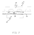
- FIG. 6 is a side view of the distal end of the suspension shown in FIG. 1 .
- FIG. 7 is a closer view of the portion of FIG. 6 showing the dimple, motor, and head slider.
- FIGS. 8A-8C are plan views of the stainless steel side of the flexure shown in FIG. 1 , illustrating the operation of the DSA structure.
- FIG. 9 is an isometric view of the loadbeam side of a suspension having a flexure with a dual stage actuation (DSA) structure.
- DSA dual stage actuation
- FIG. 10 is an isometric view of the loadbeam side of the distal end of the suspension shown in FIG. 9 .
- FIG. 11 is an isometric view of the flexure side (i.e., the side opposite that shown in FIG. 10 ) of the distal end of the suspension shown in FIG. 9 .
- FIG. 12 is an isometric view of the stainless steel side of the flexure shown in FIG. 9 .
- FIG. 13A is an isometric view of the trace side (i.e., the side opposite that shown in FIG. 12 ) of the flexure shown in FIG. 9 .
- FIG. 13B is the view of FIG. 13A but with the head slider removed.
- FIG. 13C is the view of FIG. 13B but with the motor removed.
- FIG. 13D is the view g of FIG. 13C but with the coverlay removed.
- FIG. 13E is the view of FIG. 13D but with the conductive material layer removed.
- FIG. 13F is the view of FIG. 13E but with the dielectric material layer removed.
- FIG. 14 is a side view of the distal end of the suspension shown in FIG. 9 .
- FIG. 15 is a closer view of the portion of FIG. 14 showing the dimple, motor, and head slider.
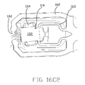
- FIGS. 16A 1 , 16 B 1 , and 16 C 1 are plan views of the stainless steel side of the flexure shown in FIG. 9 .
- FIGS. 16A 2 , 16 B 2 , and 16 C 2 are plan views of the trace side of the flexure shown in FIGS. 16A 1 , 16 B 1 , and 16 C 1 , respectively.
- FIG. 17 is an isometric view of a tri-stage actuated suspension.
- FIG. 18A is an isometric view of the stainless steel side of the distal end of a flexure having a DSA structure in accordance with another embodiment of the invention.
- FIG. 18B shows the view of FIG. 18A but with the motor removed.
- FIG. 18C shows the view of FIG. 18B but with damper and adhesive material removed.
- FIG. 19 is an isometric view of the trace side of the distal end of the flexure shown in FIG. 18A .
- FIG. 20 is an isometric view of the stainless steel side of the distal end of a flexure in accordance with another embodiment.
- FIG. 21 is an isometric illustration of a motor.
- FIG. 22 is an isometric illustration of an alternative motor.
- FIG. 23 is an isometric view of the stainless steel side of the distal end of a flexure and DSA structure in accordance with another embodiment.
- FIG. 24 is an isometric view of the stainless steel side of the distal end of a flexure and DSA structure in accordance with another embodiment.
- FIG. 25 is a side view of the flexure shown in FIG. 24 .
- FIG. 26 is an isometric of the trace side of a flexure having a trace side DSA structure in accordance with another embodiment.
- FIG. 27 is an isometric view of the stainless steel side of the flexure shown in FIG. 26 .
- FIG. 28 is a side view of the flexure shown in FIGS. 26 and 27 .
- FIG. 29 is an isometric view of the head slider shown in FIGS. 25-28 .
- FIG. 30 is an isometric view of the stainless steel side of the distal end of a flexure in accordance with another embodiment.
- Flexure 12 includes a gimbal 24 at the distal end of the flexure 12 .
- a DSA structure 14 is located on the gimbal 24 , adjacent the distal end of the loadbeam 18 .
- the suspension 10 includes a gimbal limiter 26 comprising a tab 28 configured to engage a stop portion 30 of the loadbeam 18 .
- a head slider 32 is mounted to a head slider mounting or tongue 33 of the gimbal 24 , on the side of the suspension 10 that is opposite the loadbeam 18 .
- DSA structure 14 includes a motor 34 , which is a PZT or other piezoelectric actuator in the illustrated embodiment, mounted to the gimbal 24 of the flexure 12 between the loadbeam 18 and the head slider 32 .
- the motor 34 can be a single layer or multi-layer piezoelectric structure. In a multi-layered embodiment, anode and cathode layers can alternate through the total thickness of the motor 34 .
- the motor drives portions of the gimbal 24 , including the tongue 33 and head slider 32 , about a generally transverse tracking axis.
- Proximal and distal refers to the relative direction along the longitudinal axis of the suspension while lateral refers to the left and/or right directions orthogonal to the longitudinal axis of the suspension.
- the baseplate 16 is proximal of the loadbeam 18 while opposite ends of the motor 34 extend laterally.
- FIGS. 4A and 4B are isometric views of the stainless steel side of the flexure 12 and DSA structure 14 shown in FIG. 1 .
- the motor 34 is not shown in FIG. 4B to show further details of the tongue 33 .
- FIGS. 5A-5F are isometric views of the trace side (i.e., the side opposite that shown in FIGS. 4A and 4B ) of the flexure 12 and DSA structure 14 .
- FIGS. 5A-5F show the various layers that comprise the flexure 12 and DSA structure 14 .
- FIG. 5B is the drawing of FIG. 5A but with the head slider 32 removed to further show details of the tongue 33 .
- FIG. 5C is the drawing of FIG.
- FIG. 5B is the drawing of FIG. 5B but with a polyimide coverlay 46 removed to reveal a conductive material layer 44 including traces 60 and other structures formed in the conductive material layer that is otherwise underneath the polyimide coverlay 46 .
- FIG. 5D is the drawing of FIG. 5C but with the conductive material layer 44 removed to more fully reveal the dielectric layer 42 that is otherwise underneath the conductive material layer 44 .
- FIG. 5E is the drawing of FIG. 5D but with the dielectric layer 42 removed to show only the stainless steel layer 40 and the motor 34 .
- FIG. 5F is the drawing of FIG. 5E but with the motor 34 removed to illustrate only the stainless steel layer 40 of the flexure 12 . It will be understood that the stainless steel layer 40 could alternatively be formed from another metal or rigid material.
- the flexure 12 is formed from overlaying spring metal such as stainless steel layer 40 , polyimide or other dielectric layer 42 , copper or other conductive material layer 44 and polyimide coverlay 46 .
- the dielectric layer 42 generally electrically isolates structures formed in the conductive material layer 44 from adjacent portions of the stainless steel layer 40 .
- Coverlay 46 generally covers and protects the structures formed in the conductive material layer 44 .
- the gimbal 24 includes the spring arms 52 and the tongue 33 .
- the spring arms 52 extend from the base portion 50 .
- the mounting portion 54 which is part of the tongue 33 , is supported between the spring arms 52 by a pair of struts 56 that extend from support regions 58 on the distal end portions of the spring arms 52 .
- the pair of struts 56 is the only part of the stainless steel layer 40 that connects or otherwise supports the tongue 33 between the spring arms 52 .
- the struts 56 can be the only structural linkage between the spring arms 52 and the tongue 33 .
- the struts 56 in connecting with the tongue 33 , can be the only part of the stainless steel layer 40 that connects between the spring arms 52 distal of the base portion 50 .
- the struts 56 are offset from one another with respect to the longitudinal axis of the flexure 12 or otherwise configured so as to provide for rotational movement of the mounting portion 54 about the tracking axis with respect to the spring arms 52 . As best shown in FIG.
- one strut 56 of the pair of struts 56 is located proximally of the motor 34 while the other strut 56 of the pair of struts 56 is located distally of the motor 34 such that the motor 34 is between the pair of struts 56 .
- Each strut 56 has a longitudinal axis that extends generally perpendicular with respect to the longitudinal axis of the suspension 10 .
- the longitudinal axes of the struts 56 extend parallel but do not intersect or otherwise overlap with each other when the struts 56 are not stressed (e.g., not bent). As shown in FIG.
- the struts 56 can each be the narrowest part of the stainless steel layer 40 in an X-Y plane (as viewed from the overhead perspective of FIG. 8B ) while the thickness of the stainless steel layer 40 can be consistent along the flexure 12 .
- the opposite ends of the motor 34 are attached (e.g., by structural adhesive such as epoxy) to the support regions 58 of the spring arms 52 .
- the support regions 58 can serve as motor mounting pads.
- Portions of the dielectric layer 42 extend underneath the struts 56 in FIG. 4B .
- a plurality of traces 60 formed in the conductive material layer 44 extend between the base portion 50 and the tongue 33 over supporting portions 62 formed in the dielectric layer 42 .
- a number of the traces 60 terminate at locations on a distal region on the tongue 33 and are configured to be electrically attached to terminals of the read/write head (not shown) on the head slider 32 .
- traces 60 terminate at a contact such as copper pad 64 on the tongue 33 , below the motor 34 .
- the copper pad 64 is located generally centrally between the spring arms 52 .
- the dielectric layer 42 has an opening over the pad 64 .
- a structural and electrical connection, e.g., using conductive adhesive, is made between the copper pad 64 and an electrical terminal on the motor 34 .
- Another electrical connection to a terminal on the motor 34 (e.g., a ground terminal) is made through the dimple 36 (i.e., the dimple 36 is in electrical contact with the terminal on the motor 34 ).
- the electrical connections to the motor 34 can be made by other approaches and structures, such as traces along the flexure 12 .
- the head slider 32 sits on the coverlay 46 of the tongue 33 .
- Coverlay 46 provides protection for the traces 60 .
- FIGS. 5A-5C which show that the supporting portions 62 are offset with respect to the longitudinal direction of the flexure 12 , portions of the traces 60 on the opposite sides of the flexure 12 are offset from each other in a manner similar to that of the struts 56 (e.g., portions of the traces overlay the struts in the illustrated embodiment). Offset traces of this type can increase the stroke performance of the DSA structure 14 .
- Various other embodiments do not have offset traces.
- the supporting portions 62 may provide negligible mechanical support to the tongue 33 relative to the struts 56 .
- FIGS. 6 and 7 are side views of the suspension 10 , illustrating the gimbal 24 and DSA structure 14 .
- the dimple 36 which is a structure formed in the stainless steel material that forms the loadbeam 18 , and which extends from the loadbeam 18 , engages the motor 34 and functions as a load point by urging the portion of the gimbal 24 to which the motor 34 is connected out of plane with respect to the base portion 50 of the flexure 12 .
- a bend or transition in the flexure 12 can occur at any desired location along the spring arms 52 due to the urging of the gimbal 24 by the dimple 36 .
- the dimple 36 can also provide an electrical contact to a terminal (not visible) on the portion of the motor 34 engaged by the dimple.
- the dimple 36 can provide an electrical ground potential or electrical connection to the terminal on the motor 34 .
- Various other embodiments include other dimple structures such as plated structures that provide these functions.
- the dimple 36 can be plated with conductive material such as gold to enhance the electrical connection to the terminal of the motor 34 which can also be plated with conductive material such as gold.
- Still other embodiments use structures other than the dimple 36 to provide a grounding or other electrical connection to the motor 34 .
- an electrical connection e.g., a ground connection
- a structure such as conductive adhesive between a terminal on the motor 34 and the conductive material pad on the support region of the flexure 12 .
- the motor 34 is structurally attached to the tongue 33 at a location between the opposite lateral end portions of the tongue 33 .
- the motor 34 is attached to the tongue 33 of the gimbal 24 in addition to the motor 34 being attached to the support regions 58 of the spring arms 52 .
- FIGS. 8A-8C are plan views of the stainless steel side of the gimbal 24 of the flexure 12 .
- the DSA structure 14 and tongue 33 are in a neutral, undriven state with the tongue 33 generally centrally located between the spring arms 52 when no tracking drive signal is applied to the motor 34 .
- a first potential (e.g., positive) tracking drive signal is applied to the motor 34 , the shape of the motor changes and its length generally expands. This change in shape increases the distance between the support regions 58 as shown in FIG.
- the struts 56 bend such that the tongue 33 rotates in the second direction. Some, although relatively little, out-of-plane motion of other portions of the gimbal 24 is produced during the tracking action of DSA structure 14 as described above. With this embodiment of this disclosure, head slider mounting on the tongue 33 generally rotates with respect to the spring arms 52 as the spring arms 52 stay stationary or experience little movement.
- the suspension 110 includes a loadbeam 118 having a rigid or beam region 20 coupled to the baseplate 116 along a spring or hinge region 122 .
- the loadbeam 18 can be formed from stainless steel.
- Flexure 112 includes a gimbal 124 at its distal end.
- a DSA structure 114 is located on the gimbal 124 , adjacent the distal end of the loadbeam 118 .
- the illustrated embodiment of the suspension 110 also includes a gimbal limiter 126 comprising a tab 128 configured to engage a stop portion 130 of the loadbeam 118 .
- the DSA structure 114 includes a motor 134 , which is a PZT actuator in the illustrated embodiment, mounted to a motor mounting region of the tongue 133 , on the side of the flexure 112 opposite the loadbeam 118 .
- a head slider 132 is mounted to the side of the motor 134 opposite the flexure 112 .
- the motor drives portions of the gimbal 124 , including portions of the tongue 133 , motor 134 and head slider 132 , about a generally transverse tracking axis.
- FIG. 12 is a detailed isometric view of the stainless steel-side of the flexure 112 and DSA structure 14 shown in FIG. 9 .
- FIGS. 13A-13F are isometric views of the flexure 112 and DSA structure 114 showing the side opposite that shown in FIG. 12 . Specifically, FIGS. 13A-13F show the various layers that comprise the flexure 112 and DSA structure 114 .
- FIG. 13B is the drawing of FIG. 13A but with the head slider 132 removed to further show details of the motor 134 on the tongue 133 .
- FIG. 13C is the drawing of FIG. 13B but with the motor 134 removed to reveal details of the tongue 133 .
- FIG. 13D is the drawing of FIG.
- FIG. 13C is the drawing of FIG. 13D but with the conductive material layer 144 removed to further reveal the dielectric layer 142 .
- FIG. 13F is the drawing of FIG. 13E but with the dielectric layer 142 removed to show only the stainless steel layer 140 of the flexure 112 .
- the stainless steel layer 140 could alternatively be formed from another metal or rigid material.
- the flexure 112 is formed from overlaying spring metal such as stainless steel layer 140 , polyimide or other dielectric layer 142 , copper or other conductive material layer 144 , and coverlay 146 .
- the dielectric layer 142 generally electrically isolates structures formed in the conductive material layer 144 from adjacent portions of the stainless steel layer 140 .
- Coverlay 146 generally covers and protects the structures formed in the conductive material layer 144 .
- the gimbal 124 includes spring arms 152 and the tongue 133 .
- the base portion 150 , the spring arms 152 , and the center region 154 are each formed from the stainless steel layer 140 .
- the spring arms 152 extend from the base portion 150 .
- the center region 154 which is a center part of the tongue 133 , is connected to the distal ends of the spring arms 152 and is supported between the spring arms 152 .
- Also formed in the stainless steel layer 140 is a pair of struts 153 . Each of the struts 153 extends from one of the opposite lateral sides of the center region 154 and has a motor mounting flag or pad 155 on its outer end.
- the struts 153 are offset from one another with respect to the longitudinal axis of the flexure 112 or otherwise configured so as to provide for rotational movement of the motor 134 and the head slider 132 mounted thereto about the tracking axis with respect to the center region 154 .
- Each strut 153 comprises a longitudinal axis that extends generally perpendicular with respect to the longitudinal axis of the suspension 110 .
- the longitudinal axes of the struts 153 extend parallel but do not intersect or otherwise overlap with each other when the struts 153 are not stressed (e.g., not bent).
- the struts 153 can be the only structural linkage between the center region 154 and the pads 155 (e.g., the only part of the stainless steel layer 140 connecting the center region 154 with the pads 155 is the struts 153 , a single strut 153 for each pad 155 ). As shown in FIG. 13F , the struts 153 can each be the narrowest part of the stainless steel layer 140 in an X-Y plane (as viewed from the overhead perspective of FIG. 16B 1 ) while the thickness of the stainless steel layer 140 can be consistent along the flexure 112 .
- a plurality of traces 160 are formed in the conductive material layer 144 and extend between the base portion 150 and tongue 133 along paths generally laterally outside the spring arms 152 and over supporting portions 162 formed in the dielectric layer 142 .
- a number of the traces 160 terminate at locations adjacent the distal region of the tongue 133 and are configured to be electrically attached to read/write head terminals (not shown) on the head slider 132 .
- a pair of power traces 161 for powering the motor 134 are also formed in the conductive material layer 144 , and extend between the base portion 150 and a proximal portion of the tongue 133 along paths generally inside the spring arms 152 and over supporting portions 163 formed in the dielectric layer 142 .
- the motor power traces 161 terminate at a first motor terminal pad 167 on one of the motor mounting pads 155 .
- a second motor terminal pad 169 is formed in the conductive material layer 144 on the other motor mounting pad 155 , and is coupled by a trace 171 to a conductive via 173 that is shown on the tongue 133 at a location between the motor mounting pads 155 .
- via 173 extends through an opening 175 in the dielectric layer 142 (shown in FIG. 13E ) to electrically contact the stainless steel layer 140 of the flexure 112 .
- the motor terminal pad 169 can be electrically connected to a ground potential at the stainless steel layer 140 by the trace 171 and the via 173 . As shown in FIG.
- FIG. 13E also illustrates other holes in the dielectric layer that can be used in connection with conductive vias to electrically connect (e.g., ground) traces and other structures in the conductive material layer 144 to the stainless steel layer 140 .
- conductive vias to electrically connect (e.g., ground) traces and other structures in the conductive material layer 144 to the stainless steel layer 140 .
- other approaches and structures can be used to couple the tracking drive signals to the terminals on the motor 134 .
- the electrical terminals on the motor 134 may be on the same side (e.g., top or bottom) but opposite longitudinal ends of the motor 134 .
- the motor 134 can be attached to the gimbal 124 by bonding the electrical terminals of the motor 134 to the motor terminal pads 167 and 169 using conductive adhesive.
- the motor 134 is both structurally and electrically connected to the gimbal 124 .
- the motor terminal pads 167 and 169 are exposed through openings in the coverlay 146 to provide access for the conductive adhesive.
- FIGS. 14 and 15 are side views of the suspension 110 , illustrating the gimbal 124 and DSA structure 114 .
- the dimple 136 which is a structure formed in the stainless steel of the loadbeam 118 and which projects from the loadbeam 118 , engages the center region 154 of stainless steel layer 140 on the side of the tongue 133 opposite the motor 134 .
- Dimple 136 functions as a load point by urging the portion of the gimbal 124 to which the motor 134 is connected out of plane with respect to the base portion 150 of the flexure 112 .
- the motor 134 is located between the tongue 133 and the head slider 132 (e.g., the motor 134 is sandwiched in a vertical axis).
- the head slider 132 is structurally supported by the motor 134 such that the only structural linkage between the flexure 112 and the head slider 132 runs through or otherwise includes the motor 134 .
- the manner by which the stainless steel tabs 157 locate the portion of dielectric layer 142 with the terminal ends of the traces 160 at the correct z-height and adjacent to the portion of the head slider 132 that includes the read/write head terminals is shown in FIG. 15 .
- FIGS. 16A 1 , 16 A 2 , 16 B 1 , 16 B 2 , 16 C 1 and 16 C 2 are plan views of the gimbal 124 of the flexure 112 .
- FIGS. 16A 1 , 16 B 1 and 16 C 1 illustrate the stainless steel side of the flexure 112
- FIGS. 16A 2 , 16 B 2 and 16 C 2 illustrate the trace side of the flexure 112 , with the motor 134 and head slider 132 shown. As shown in FIGS.
- the struts 153 are not bent or otherwise stressed in this state.
- a first potential (e.g., positive) tracking drive signal is applied to the motor 134 , the shape of the motor changes and its length generally expands.
- This change in shape increases the distance between the motor mounting pads 155 , which in connection with the mechanical action of the linking struts 153 , causes the motor 134 , and therefore the head slider 132 mounted thereto, to move or rotate in a first direction with respect to the longitudinal axis of the flexure 112 about the tracking axis.
- the lengthening of the motor 134 stretches the struts 153 laterally and causes the struts 153 to bend (e.g., bow inward). Because of the offset arrangement of the struts 153 , the struts 153 bend such that the motor 134 and the head slider 132 rotate in the first direction.
- a second potential (e.g., negative) tracking drive signal when a second potential (e.g., negative) tracking drive signal is applied to the motor 134 , the shape of the motor changes and its length generally contracts. This change in shape decreases the distance between the motor mounting pads 155 , which in connection with the mechanical action of the linkage including struts 153 , causes the motor 134 , and therefore the head slider 132 mounted thereto, to move or rotate in a second direction with respect to the longitudinal axis of the flexure 112 about the tracking axis.
- the second direction is opposite the first direction.
- the shortening of the motor 134 compresses the struts 153 laterally and causes the struts 153 to bend (e.g., bow outward). Because of the offset arrangement of the struts 153 , the struts 153 bend such that the motor 134 and the head slider 132 rotate in the second direction.
- FIG. 17 is an illustration of a suspension 210 in accordance with another embodiment of this disclosure.
- the suspension 210 includes a co-located or gimbal-based DSA structure 214 and a loadbeam or baseplate-type DSA structure 290 .
- the suspension 210 is a tri-stage actuated suspension.
- the DSA structure 214 is substantially the same as the DSA structure 114 described above (e.g., is configured with any aspect described or shown in connection with FIGS. 9-16C 2 ) except as otherwise specified or shown.
- the DSA structure 214 is substantially the same as the DSA structure 14 described above (e.g., is configured with any aspect described or shown in connection with FIGS. 1-8C ) except as otherwise specified or shown.
- Other embodiments of suspension 210 include other gimbal-based DSA structures.
- the DSA structure 290 can be any known or conventional DSA structure such as any of those described above in the background section.
- FIG. 18A is an isometric view of a stainless steel side of a flexure 312 having a gimbal 324 with a DSA structure 314 .
- FIG. 18B is an isometric view of the flexure 312 of FIG. 18A but with the motor 334 removed to show additional detail.
- FIG. 18C is an isometric view of the flexure 312 of FIGS. 18A-B but with dampener 329 , island 325 , and adhesive 335 structures further removed to show additional detail.
- FIG. 19 shows an isometric view of the trace side of the flexure 312 (i.e., the side opposite that shown in FIGS. 18A-C ).
- coverlay 346 extends over the trace side of the flexure 312 to insulate traces.
- the flexure 312 , DSA structure 314 , or other component can be similar to that of the flexure 12 , 112 , 212 , the DSA structure 14 , 114 , 214 , or other component described above or elsewhere referenced herein except where noted. Features that are the same or similar to those of other embodiments are indicated by similar reference numbers.
- FIG. 18A shows a motor 334 mounted on the flexure 312 .
- the lateral ends of the motor 334 can be attached to the support regions 358 of the spring arms 352 .
- layers of adhesive 335 can be positioned on the support regions 358 of the spring arms 352 .
- the motor 334 extends over the tongue 333 .
- the layers of adhesive 335 can be non-conductive epoxy, for example.
- the motor 334 can be electrically activated to bend the struts 356 and move the tongue 333 , and move a head slider attached thereto (not illustrated), about a tracking axis, as discussed herein.
- a head slider can be mounted in any manner referenced herein in connection with any other embodiment.
- a damper 329 is located on the tongue 333 below the motor 334 (having been removed for this view).
- the damper 329 is a layer of material on a surface of the tongue 333 and between the stainless steel layer 340 and the motor 334 .
- the damper 329 is located on the tongue 333 directly underneath the motor 334 .
- the damper 329 does not extend out from underneath the motor 334 (i.e. the damper 329 is entirely located directly between the tongue 333 and the motor 334 ).
- the damper 329 may extend out from underneath the motor 334 to cover one or more areas of the tongue 333 that are not also overlapped by the motor 334 .
- the damper 329 enhances the performance of the DSA structure 314 .
- the damper 329 can be formed from elastic or visco-elastic material. Visco-elastic materials can provide enhanced damping benefits. Examples of suitable materials include 3MTM 242 and JDC MP65 materials. These materials typically have a relatively low elastic modulus and therefore have low stiffness.
- the damper 329 can be formed by various techniques such as jetting or pin contacting the material in liquid form onto the stainless steel layer 340 or other surface of the tongue 333 , or by applying a previously formed film of the material onto the stainless steel layer 340 or other surface of the tongue 333 .
- the material of the damper 329 may be adhesive and therefore can adhere to the tongue 333 (e.g., to the stainless steel layer 340 ) and/or the motor 334 (e.g., to the bottom side of the motor 334 ). In any case, the material of the damper 329 can contact both the tongue 333 (e.g., the stainless steel layer 340 ) and the motor 334 (e.g., the bottom side of the motor 334 ).
- the damper 329 can be placed at the center of motion between the tongue 333 and the motor 334 .
- the damper 329 can extend over a center of rotational motion (e.g., a tracking axis) of the tongue 333 .
- the damper 329 can reduce unintended motion (e.g., motion that is not rotation) between the tongue 333 and the motor 334 .
- the damper 329 is placed into shear by the relative movement between the tongue 333 and the motor 334 .
- the damper 329 material changes the shear motion into heat energy, therefore reducing or dampening unintended motion.
- the damper 329 can help to keep the motor 334 in a generally parallel planar relationship with the tongue 333 during operation of the DSA structure 314 .
- a first plane aligned with the flat orientation of the motor 334 can remain parallel, or generally parallel, with a second plane aligned with the flat orientation of the tongue 333 during operation of the DSA structure 314 due to the damper 329 .
- the motor 334 and/or the flexure 312 may otherwise be prone to bending out of the planar parallel relationship when the motor 334 is activated and the DSA structure 314 articulates.
- the damper 329 can stabilize the movement of the motor 334 with respect to the flexure 312 during activation of the motor 334 without rigidly fixing the motor 334 to the flexure 312 , such that the motor 334 is allowed some movement with respect to the tongue 333 , as needed for articulation of the DSA structure 314 , but out of plane movement is reduced or eliminated. Stabilizing the motor 334 with respect to the flexure 312 , and thereby reducing out of plane motion, increases the linear stroke of the motor 334 which increases the tracking efficiency of the DSA structure 314 .
- the damper 329 can reduce or eliminate out-of-plane motion of the tongue 333 during high frequency resonance modes, thereby providing lower gain and higher servo bandwidth capabilities for a disk drive into which the flexure 312 is incorporated. Flexure mode bending gains can also be improved. The higher servo bandwidths provided by the DSA structure 314 also allow tracks on the disk surface (not shown) to be placed closer together and thereby provide for higher capacity disk drives. In general, the greater the area directly between the motor 334 and the stainless steel layer 340 that is covered by damper 329 , the greater the benefits and advantages such as those described above that can be achieved. Dampers such as that described herein can also be incorporated into other DSA structures in a similar configuration, such as between the flexure and motors in the DSA structures of FIGS. 1-17 or others referenced elsewhere herein.
- FIG. 18B also shows an island 325 .
- the island 325 can be formed from an electrically conductive material, such as copper or other metal or a conductive adhesive, for example.
- the island 325 provides an electrical connection between a trace contact (not visible) of the flexure 312 and a terminal on the bottom side of the motor 334 (i.e. a side of the motor 334 facing the flexure 312 . These terminals are not shown in FIG. 18B but are further discussed herein.
- the island 325 can be connected to the terminal on the motor 334 by conductive epoxy, solder, or by any other means referenced herein or known for making an electrical connection.
- the island 325 is surrounded (e.g., in a X-Y plane co-planar with the top surface of the tongue 333 ) by a void 327 .
- the void 327 extends through the stainless steel layer 340 and the damper 329 .
- the void 327 can be considered a moat because the void 327 entirely surrounds the sides of the island 325 and isolates the island 325 from the stainless steel layer 340 and/or the damper 329 .
- the void 327 can electrically isolate the island 325 from the stainless steel layer 340 or various other conductive materials.
- conductive adhesive, solder, or other material can be used to electrically connect the island 325 to a terminal on the bottom side of the motor 334 .
- the void 327 can stop or minimize undesirable wicking of the conductive adhesive or other material thereby effectively defining the size of the connection. Isolation of the island 325 provided by the void 327 can prevent conductive adhesive, solder, or other material from unintentionally creating an electrical short between the island 325 and the stainless steel layer 340 during application.
- the void 327 can be formed by known methods such as etching. For example, the stainless steel layer 340 can be etched to define the void 327 .
- a bond pad 331 is located directly under the motor 334 in an area between the struts 356 (e.g., the struts 356 being respectively proximal and distal of the bond pad 331 ) and between the support regions 358 laterally (e.g., the support regions 358 being respectively left and right of the bond pad 331 ).
- a trace of the flexure 312 can terminate at the bond pad 331 .
- the bond pad 331 could alternatively be any type of terminal. Conductive epoxy or solder (not shown) can be used to make the electrical connection between the bond pad 331 and a terminal of the motor 334 .
- a solder ball or screen printed solder can be placed on the bond pad 331 and be made to flow onto the terminal of the motor 334 .
- a motor 334 that can be used with this embodiment of the flexure 312 are described in greater detail below.
- respective electrical connections can be made through the bond pad 331 and the island 325 to two electrical contacts on the bottom side of the motor 334 (such a motor configuration is further discussed herein).
- an electrical contact between the bond pad 331 and the terminal of the motor 334 can be made using other structures and approaches.
- another electrical connection to a terminal (not shown) on the motor 334 can be through a dimple of a loadbeam as described above.
- bond pad 331 is shown in the embodiment of FIGS. 18A-C
- another bond pad can be provided along the flexure 312 in the same configuration as the bond pad 331 but on the left side of the flexure 312 to electrically connect with a second terminal of the motor 334 .
- FIG. 20 is an illustration of the stainless steel side of a flexure 412 having a gimbal 424 with a DSA structure 414 in accordance with another embodiment.
- the flexure 412 , DSA structure 414 , and/or other component can be similar to that of the flexure 12 , 112 , 212 , 312 , DSA structure 14 , 114 , 214 , 314 , or other component described above or elsewhere referenced herein except where noted.
- a tongue 433 is supported by spring arms 452 .
- a motor is not shown in FIG. 20 to allow more detail to be shown in areas which would otherwise be obscured by the motor.
- a motor can be mounted on the flexure 412 or other component in the manner of any other embodiment referenced herein, such as that shown in FIG. 18A .
- the lateral ends of a motor can be attached to the support regions 458 of the spring arms 452 .
- a damper 429 is located on the flexure 412 in an area that would be directly below the motor.
- the damper 429 covers substantially the entire area of the tongue 433 below where the motor would be located (i.e. the area of overlap between the tongue 433 and the motor).
- the damper 429 is a layer on the stainless steel layer 440 .
- the damper 429 can be formed from materials that are the similar to or the same as that of damper 329 described above, for example.
- the DSA structure 414 includes a trace along the flexure 412 and a bond pad 431 for making an electrical contact to a terminal of the motor.
- the bond pad 431 can be configured, and can connect to a terminal of a motor, in any manner described above in connection with the bond pad 331 of FIGS. 18B-C , for example.
- Other structures and approaches such as those described above can be used to make additional or other electrical contacts to the motor.
- FIG. 21 is an illustration of an embodiment of a motor 534 that can be used with DSA structures of the present disclosure.
- Motor 534 has a first electrical contact 570 on a first surface of the motor 534 (e.g., the bottom surface of the motor which faces flexure) and a second electrical contact 573 on a second surface of the motor 534 (e.g., the top surface of the motor 534 opposite the bottom surface).
- the piezoelectric material 571 of the motor 534 is located between the first electrical contact 570 and the second electrical contact 573 .
- the motor 534 can be used, for example, in embodiments in which electrical connections are made with the motor 534 from opposite sides of the motor 534 , such as connecting a bond pad 331 , 431 or island 325 to the first electrical contact 570 on the first surface of the motor 534 and electrically connecting another terminal (e.g., a dimple of a loadbeam as a grounding contact) to the second electrical contact 573 on the second surface of the motor 534 .
- another terminal e.g., a dimple of a loadbeam as a grounding contact
- FIG. 22 is an illustration of another embodiment of a motor 634 that can be used with DSA structures of the present disclosure.
- the motor 634 has a first electrical contact 670 and a second electrical contact 672 . Both of the first electrical contact 670 and the second electrical contact 672 extend along a first side (e.g., the bottom) of the motor 634 .
- the second electrical contact 672 which is located at one end of the first side of the motor 634 , is formed by an electrical terminal wrapping from a second side (e.g., the top) of the motor 634 opposite the first side, around an end side, and to the first side of the motor 634 .
- the first electrical contact 670 which is located at the opposite end of the first side of the motor 634 with respect to the second electrical contact 672 , can be limited to the first side of the motor 634 or can extend to one or more other sides of the motor 634 .
- the first electrical contact 670 and the second electrical contact 672 can be formed by plating the piezoelectric material of the motor 634 with conductive material. As shown, the first electrical contact 670 and the second electrical contact 672 are electrically isolated on the first side of the motor 634 by a gap 674 .
- the gap 674 can be a non-conductive surface of the first side of the motor 634 .
- both electrical connections to the motor 634 e.g., anode and cathode
- Such embodiments can include those where two different and electrically separate traces of flexure respectively connect to the bottom side of the motor 634 .
- the island 325 and the bond pad 331 can electrically connect with the first electrical contact 670 and the second electrical contact 672 , respectively.
- two separate bond pads could be provided, each of the bond pads electrically connected to different, and electrically separate, traces of flexure.
- the island 325 and the bond pad 331 can be positioned directly below the first electrical contact 670 and the second electrical contact 672 , respectively, when the motor 634 is mounted on the flexure.
- a first bond pad can be positioned in the manner of bond pad 331 , 431 on a right side of the flexure while the second bond pad can be positioned in a mirrored manner with respect to the first bond pad on the left side of the flexure.
- the first and second bond pads can be positioned between the support regions 358 , 458 and the lateral sides of the tongue 333 , 433 (e.g., the left and right edges of the tongue 333 , 433 ), respectively.
- Respective electrical connections can be made to the two bond pads and the first electrical contact 670 and the second electrical contact 672 , such as with solder or conductive epoxy. Being that two separate electrical connections are made to the bottom side of the motor 634 , a dimple of a loadbeam does not need to provide an electrical connection to the motor 634 .
- a dimple of a loadbeam that engages a motor or an element mounted on the motor can be electrically isolated from the terminals of the motor using elastic or visco-elastic materials such as those described above.
- one or more materials can be provided on the motor to electrically insulate and mechanically protect the motor.
- FIG. 23 is an isometric view of the stainless steel side of a flexure 712 having a gimbal 724 with a DSA structure 714 in accordance with another embodiment.
- the flexure 712 , the DSA structure 714 , and/or other component can be similar to that of the flexure 12 , 112 , 212 , 312 , 414 , DSA structure 14 , 114 , 214 , 314 , 414 , and/or other component described above or other structure referenced herein except where noted.
- FIG. 23 shows a motor 734 .
- the lateral ends of the motor 734 can be attached to the support regions 758 of the spring arms 752 . As demonstrated in FIG. 18B , layers of adhesive can be positioned on the support regions 758 of the spring arms 752 .
- the motor 734 extends over the tongue 733 .
- the motor 734 can be electrically activated to bend the struts 756 and move the tongue 733 , and a head slider 732 attached thereto, about a tracking axis, as discussed herein.
- the top side of the motor 734 opposite the bottom side of the motor 734 which faces the tongue 733 , includes an impingement element 788 .
- the impingement element 788 comprises multiple layers.
- a top layer 737 of the impingement element 788 can comprise a layer of metal (e.g., stainless steel), plastic, or other material that is relatively hard to robustly engage a dimple of a loadbeam which impinges on the top layer 737 of the impingement element 788 , thereby mechanically protecting the motor 734 from wear from the impinging dimple.
- the impingement element 788 includes a second layer 739 below the top layer 737 . The second layer 739 can be adhered to the top layer 737 and the top side of the motor 734 .
- the second layer 739 can comprise elastic or visco-elastic material. Characteristics and examples of elastic or visco-elastic materials are discussed herein.
- the second layer 739 can electrically insulate a terminal on the top side of the motor 734 from the top layer 737 .
- the impingement element 788 can be a single layer of one of the materials discussed herein (e.g., metal, plastic, elastic, visco-elastic). It is noted that the top side of the motor 734 can comprise an electrical contact, such as in the case of motor 634 .
- the impingement element 788 can be located on the electrical contact.
- the impingement element 788 can then provide a layer of insulating material (e.g., the second layer 739 ) disposed on the electrical contact to insulate the electrical contact from the dimple.
- An electrical connection can be made to the electrical contact on the top side of the motor 734 by the electrical contact extending from the top side of the motor 734 to another side of the motor (e.g., the bottom side) and an electrical connection being made to the electrical contact on the another side of the motor (e.g., via a bond pad connecting to an electrical contact extending to the bottom side of the motor 734 , as discussed herein).
- a differential motor drive signal can be applied to the motor 734 (e.g., a positive voltage applied to a first terminal of the motor and a negative voltage applied to a second terminal of the motor 734 ) to increase the stroke capability (e.g., due to the larger voltage difference across the piezoelectric material of the motor 734 ).
- FIG. 24 is an illustration of the stainless steel side of a flexure 812 having a gimbal 824 with a DSA structure 814 in accordance with another embodiment.
- FIG. 25 is a side view of the gimbal 824 of FIG. 24 .
- the flexure 812 , DSA structure 814 , or other component can be similar to that of the flexure 12 , 112 , 212 , 312 , 412 , 712 , the DSA structure 14 , 114 , 214 , 314 , 414 , 714 or other component described above or elsewhere referenced herein except where noted.
- Features that are the same or similar to those of other embodiments are indicated by similar reference numbers.
- a damper as described herein can be provided on the DSA structure 814 between the tongue 833 and motor 834 .
- the motor 834 is mounted on the flexure 812 opposite the head slider 832 .
- the lateral ends of the motor 834 can be attached to the support regions 858 of the spring arms 852 via adhesive 835 .
- the motor 834 extends over the tongue 833 .
- the motor 834 can be electrically activated to bend the struts 856 and move the tongue 833 , and a head slider (not illustrated) attached thereto, about a tracking axis, as discussed herein.
- a load point feature 880 is located on the top side of the motor 834 .
- the load point feature 880 is shown as a dimple having a generally spherical surface in the embodiment of FIGS.
- the load point feature 880 can be formed from adhesive, epoxy, or polymer materials, for example. While a dimple of a loadbeam, such as that of FIG. 6 , may impinge on a motor or other element of the DSA structure to allow gimballing of a head slider, the embodiment of FIGS. 24-25 locates the load point feature 880 on the motor 834 to impinge on a surface of a loadbeam and allow gimballing. The loadbeam therefore does not need a protruding load point feature, and as such a loadbeam may not have a dimple that engages with the flexure 812 .
- the load point feature 880 can provide electrical isolation of the loadbeam from the top side of the motor 834 (and any electrical contact thereon) as well as distributing the stress of the preload force on the motor 834 to reduce stress.
- the load point feature 880 can also reduce wear at the load point feature 880 -motor interface, as compared to a metal dimple of a loadbeam impinging on a motor, because the apex of the load point feature 880 will ride on the flat metal surface of the loadbeam (presuming the loadbeam does not have a dimple).
- FIG. 26 is an isometric view of the trace side of a flexure 912 having a gimbal 924 with a DSA structure 914 in accordance with another embodiment.
- FIG. 27 is an isometric view of the stainless steel side of the flexure 912 of FIG. 26 .
- FIG. 28 is a side view of the DSA structure 914 of FIG. 26 .
- FIG. 29 is an isometric view of the head slider 632 of the DSA structure 614 .
- the flexure 912 , DSA structure 914 , or other component can be similar to that of the flexure 12 , 112 , 212 , 312 , 412 , 712 , 812 , the DSA structure 14 , 114 , 214 , 314 , 414 , 714 , 814 , or other component described above or elsewhere referenced herein except where noted.
- Features that are the same or similar to those of other embodiments are indicated by similar reference numbers.
- the motor 934 is mounted on the flexure 912 . Specifically, the lateral ends of the motor 934 are attached to the coverlay 946 on the support regions 958 of the spring arms 952 . As shown in FIG. 26 , the coverlay 946 extends over supporting portions 962 . A bond pad 931 is located on the flexure 912 directly under the motor 934 .
- a damper of elastic or visco-elastic material can be located between the motor 934 and the tongue 933 in the manner of any embodiment discussed herein.
- the damper can be attached to one or both of the motor 934 and the coverlay 946 .
- the damper can be disposed directly beneath the motor 934 .
- a load point (e.g., a dimple) of a loadbeam, such as that described in connection with FIGS. 1-17 , can engage the tongue 933 opposite the motor 934 .
- the dimple can engage the stainless steel layer 940 .
- the head slider 932 includes a channel 990 .
- the channel 990 can be a trough in a bottom or top side of the head slider 932 that extends from a first side of the head slider 932 to a second side of the head slider 932 opposite the first side.
- the motor 934 extends within the channel 990 while the motor 934 is not coupled to the head slider 932 .
- the length of the motor 934 is greater than that of the head slider 932 such that the motor 934 extends beyond both opposite lateral ends of the head slider 932 .
- the channel 990 can have a width greater than the width of the motor 934 to provide clearance for the motor 934 .
- the channel 990 provides clearance that enables the head slider 932 to move with the tongue 933 independently from movement of the motor 934 during actuation of the DSA structure 614 .
- the motor 934 extends through the channel 990 and the motor 934 is free from fixed contact with the head slider 932 .
- the clearance allows the motor 934 to move within the channel 990 during activation of the motor 934 and tracking of the DSA structure 914 .
- the motor 934 is entirely within the channel 990 along the length of the channel 990 such that the motor 934 does not protrude above (or below) the channel 990 but does extend from the lateral ends of the channel 990 at the lateral edges of the head slider 932 .
- the head slider 932 is mounted on the tongue 933 . Specifically, the opposite ends 992 of the head slider 932 , on opposite sides of the channel 990 , are attached by adhesive to the head slider mountings 947 on the tongue 933 .
- the head slider mountings 947 can be surfaces of the tongue 933 , such as surfaces of the coverlay 946 , to which the opposite ends 992 of the head slider 932 can be adhered.
- An advantage of the DSA structure 914 is that the overall height is reduced by incorporating the motor 934 into the channel 990 of the head slider 932 .
- the motor 934 can be electrically activated to bend the struts 956 and move the head slider 932 about a tracking axis, as discussed herein.
- FIG. 30 is an illustration of the stainless steel side of a flexure 1012 having a gimbal 1024 with a DSA structure 1014 in accordance with another embodiment.
- the flexure 1012 , DSA structure 1014 , or other component can be similar to that of the flexure 12 , 112 , 212 , 312 , 412 , 712 , 912 , the DSA structure 14 , 114 , 214 , 314 , 414 , 714 , 914 , or other component described above or elsewhere referenced herein except where noted.
- a motor (not shown) can be mounted on the flexure 1012 .
- the lateral ends of the motor can be attached to the support regions 1058 of the spring arms 1052 via adhesive, as discussed herein.
- a motor (not illustrated) can be electrically activated to bend the struts 1056 and move the tongue 1033 , and also move a head slider (not illustrated) attached thereto, about a tracking axis, as discussed herein.
- the motor can extend over the tongue 1033 .
- the motor can extend directly over the damper 1029 .
- the damper 1029 can be entirely underneath the motor such that the damper 1029 does not extend distally or proximally beyond the motor.
- the damper 1029 is a layer on the stainless steel layer 1040 .
- the damper 1029 can be configured in any manner referenced herein.
- the damper 1029 can be formed from an elastic or visco-elastic material that contacts, and further can be adhered to, the stainless steel layer 1040 and/or the motor.
- the damper 1029 has a circular outer profile. Specifically, the damper 1029 is in the shape of a circle. As shown, the damper 1029 does not include a void or a conductor extending through the damper 1029 (e.g., an island), however a void and/or a conductor as described herein can be provided within the damper 1029 .
- Embodiments of the present disclosure can offer important advantages. For example, servo bandwidth can be significantly increased (e.g., from about 3-4 kHz for baseplate or loadbeam based DSA structures to 8 kHz or more for gimbal based DSA structures).
- any of the embodiments presented herein can be modified in view of the features presented in commonly owned U.S. patent application Ser. No. 14/026,427, entitled CO-LOCATED GIMBAL-BASED DUAL STAGE ACTUATION DISK DRIVE SUSPENSIONS, filed Sep. 13, 2013, and U.S. patent application Ser. No. 14/044,238, entitled CO-LOCATED GIMBAL-BASED DUAL STAGE ACTUATION DISK DRIVE SUSPENSIONS WITH MOTOR STIFFENERS, filed Oct. 2, 2013, each of which is incorporated herein by reference in its entirety. Likewise, any of the embodiments presented in such applications can be modified with any of the features of the present disclosure.
- a suspension can include two or more motors. Such motors can be dampened and/or can include any feature as discussed herein.
- a DSA structure can having two motors mounted on a gimbaled flexure, each motor dampened and/or including any other feature discussed herein.
- Various embodiments of suspensions having two motors are disclosed in commonly owned U.S. patent application Ser. No. 13/972,137, entitled CO-LOCATED GIMBAL-BASED DUAL STAGE ACTUATION DISK DRIVE SUSPENSIONS WITH OFFSET MOTORS, filed Aug. 21, 2013, which is incorporated herein by reference in its entirety.
Abstract
Description
Claims (30)
Priority Applications (2)
| Application Number | Priority Date | Filing Date | Title |
|---|---|---|---|
| US14/050,660 US8896968B2 (en) | 2012-10-10 | 2013-10-10 | Co-located gimbal-based dual stage actuation disk drive suspensions with dampers |
| US14/467,582 US9240203B2 (en) | 2012-10-10 | 2014-08-25 | Co-located gimbal-based dual stage actuation disk drive suspensions with dampers |
Applications Claiming Priority (2)
| Application Number | Priority Date | Filing Date | Title |
|---|---|---|---|
| US201261711988P | 2012-10-10 | 2012-10-10 | |
| US14/050,660 US8896968B2 (en) | 2012-10-10 | 2013-10-10 | Co-located gimbal-based dual stage actuation disk drive suspensions with dampers |
Related Child Applications (1)
| Application Number | Title | Priority Date | Filing Date |
|---|---|---|---|
| US14/467,582 Continuation US9240203B2 (en) | 2012-10-10 | 2014-08-25 | Co-located gimbal-based dual stage actuation disk drive suspensions with dampers |
Publications (2)
| Publication Number | Publication Date |
|---|---|
| US20140098440A1 US20140098440A1 (en) | 2014-04-10 |
| US8896968B2 true US8896968B2 (en) | 2014-11-25 |
Family
ID=50432477
Family Applications (2)
| Application Number | Title | Priority Date | Filing Date |
|---|---|---|---|
| US14/050,660 Active US8896968B2 (en) | 2012-10-10 | 2013-10-10 | Co-located gimbal-based dual stage actuation disk drive suspensions with dampers |
| US14/467,582 Active US9240203B2 (en) | 2012-10-10 | 2014-08-25 | Co-located gimbal-based dual stage actuation disk drive suspensions with dampers |
Family Applications After (1)
| Application Number | Title | Priority Date | Filing Date |
|---|---|---|---|
| US14/467,582 Active US9240203B2 (en) | 2012-10-10 | 2014-08-25 | Co-located gimbal-based dual stage actuation disk drive suspensions with dampers |
Country Status (3)
| Country | Link |
|---|---|
| US (2) | US8896968B2 (en) |
| JP (1) | JP6356682B2 (en) |
| WO (1) | WO2014059128A2 (en) |
Cited By (10)
| Publication number | Priority date | Publication date | Assignee | Title |
|---|---|---|---|---|
| US9070392B1 (en) * | 2014-12-16 | 2015-06-30 | Hutchinson Technology Incorporated | Piezoelectric disk drive suspension motors having plated stiffeners |
| US9117466B2 (en) * | 2013-08-20 | 2015-08-25 | Nhk Spring Co., Ltd. | Disk drive suspension |
| US9330697B2 (en) | 2013-12-05 | 2016-05-03 | Hutchinson Technology Incorporated | Constrained dimple pad damper for disk drive head suspension |
| US20160240218A1 (en) * | 2015-02-17 | 2016-08-18 | Hutchinson Technology Incorporated | Partial curing of a microactuator mounting adhesive in a disk drive suspension |
| US9564154B2 (en) | 2014-12-22 | 2017-02-07 | Hutchinson Technology Incorporated | Multilayer disk drive motors having out-of-plane bending |
| US9613644B2 (en) | 2013-05-23 | 2017-04-04 | Hutchinson Technology Incorporated | Two-motor co-located gimbal-based dual stage actuation disk drive suspensions with motor stiffeners |
| US9646638B1 (en) * | 2016-05-12 | 2017-05-09 | Hutchinson Technology Incorporated | Co-located gimbal-based DSA disk drive suspension with traces routed around slider pad |
| US9734852B2 (en) | 2015-06-30 | 2017-08-15 | Hutchinson Technology Incorporated | Disk drive head suspension structures having improved gold-dielectric joint reliability |
| US9812160B2 (en) | 2010-05-24 | 2017-11-07 | Hutchinson Technology Incorporated | Low resistance ground joints for dual stage actuation disk drive suspensions |
| US9870792B2 (en) | 2013-07-15 | 2018-01-16 | Hutchinson Technology Incorporated | Disk drive suspension assembly having a partially flangeless load point dimple |
Families Citing this family (14)
| Publication number | Priority date | Publication date | Assignee | Title |
|---|---|---|---|---|
| US9001469B2 (en) | 2012-03-16 | 2015-04-07 | Hutchinson Technology Incorporated | Mid-loadbeam dual stage actuated (DSA) disk drive head suspension |
| JP6251745B2 (en) | 2012-09-14 | 2017-12-20 | ハッチンソン テクノロジー インコーポレイテッドHutchinson Technology Incorporated | Gimbal-type flexible member having two-stage starting structure and suspension |
| US8896968B2 (en) | 2012-10-10 | 2014-11-25 | Hutchinson Technology Incorporated | Co-located gimbal-based dual stage actuation disk drive suspensions with dampers |
| US8941951B2 (en) | 2012-11-28 | 2015-01-27 | Hutchinson Technology Incorporated | Head suspension flexure with integrated strain sensor and sputtered traces |
| US8891206B2 (en) | 2012-12-17 | 2014-11-18 | Hutchinson Technology Incorporated | Co-located gimbal-based dual stage actuation disk drive suspensions with motor stiffener |
| US8896970B1 (en) | 2013-12-31 | 2014-11-25 | Hutchinson Technology Incorporated | Balanced co-located gimbal-based dual stage actuation disk drive suspensions |
| US8867173B1 (en) | 2014-01-03 | 2014-10-21 | Hutchinson Technology Incorporated | Balanced multi-trace transmission in a hard disk drive flexure |
| US9892748B1 (en) | 2015-12-29 | 2018-02-13 | Magnecomp Corporation | Head suspension assembly having PZT damper with non-uniform thickness |
| US10373634B2 (en) * | 2016-06-30 | 2019-08-06 | Hutchinson Technology Incorporated | Co-located gimbal-based dual stage actuation disk drive head suspension with non-parallel motors |
| US10650851B1 (en) * | 2019-01-31 | 2020-05-12 | Seagate Technology Llc | Data storage device suspension strut damping system |
| US11900972B2 (en) * | 2020-06-10 | 2024-02-13 | Magnecomp Corporation | Non-operational shock mitigation for a suspension device |
| US11862209B2 (en) * | 2021-07-19 | 2024-01-02 | Magnecomp Corporation | Load beam including slit feature |
| JP2023092137A (en) * | 2021-12-21 | 2023-07-03 | 日本発條株式会社 | Suspension for disk device |
| US11915732B1 (en) * | 2023-06-21 | 2024-02-27 | Magnecomp Corporation | Head gimbal assembly for hard disk drive device |
Citations (313)
| Publication number | Priority date | Publication date | Assignee | Title |
|---|---|---|---|---|
| US3320556A (en) | 1963-05-23 | 1967-05-16 | Bell Telephone Labor Inc | Impedance transformer |
| US4418239A (en) | 1981-08-24 | 1983-11-29 | Oak Industries Inc. | Flexible connector with interconnection between conductive traces |
| US4422906A (en) | 1981-09-17 | 1983-12-27 | Masami Kobayashi | Process for direct gold plating of stainless steel |
| US4659438A (en) | 1980-05-29 | 1987-04-21 | Degussa Aktiengesellschaft | Process for the treatment of stainless steel for a direct galvanic gold plating |
| US5140288A (en) | 1991-04-08 | 1992-08-18 | Motorola, Inc. | Wide band transmission line impedance matching transformer |
| US5320272A (en) | 1993-04-02 | 1994-06-14 | Motorola, Inc. | Tin-bismuth solder connection having improved high temperature properties, and process for forming same |
| US5321568A (en) | 1993-04-22 | 1994-06-14 | Maxtor Corporation | Head suspension assembly with improved pitch and roll characteristics |
| US5333085A (en) | 1990-11-06 | 1994-07-26 | Seagate Technology, Inc. | Read/write gimbal with limited range of motion |
| US5427848A (en) | 1991-05-06 | 1995-06-27 | International Business Machines Corporation | Stress balanced composite laminate material |
| US5459921A (en) | 1993-11-12 | 1995-10-24 | Seagate Technology, Inc. | Method of making a disc drive actuator arm with arm compliance compensation |
| US5485053A (en) | 1993-10-15 | 1996-01-16 | Univ America Catholic | Method and device for active constrained layer damping for vibration and sound control |
| US5491597A (en) | 1994-04-15 | 1996-02-13 | Hutchinson Technology Incorporated | Gimbal flexure and electrical interconnect assembly |
| US5521778A (en) | 1994-08-30 | 1996-05-28 | International Business Machines Corporation | Disk drive with primary and secondary actuator drives |
| US5598307A (en) | 1994-04-15 | 1997-01-28 | Hutchinson Technology Inc. | Integrated gimbal suspension assembly |
| US5608590A (en) * | 1994-06-20 | 1997-03-04 | Hutchinson Technology Incorporated | Gimballing flexure with static compensation and load print intregal etched features |
| US5608591A (en) | 1995-06-09 | 1997-03-04 | International Business Machines Corporation | Integrated head-electronics interconnection suspension for a data recording disk drive |
| US5631786A (en) | 1994-05-19 | 1997-05-20 | International Business Machines Corporation | Termination pad manipulator for a laminated suspension in a data storage system |
| US5636089A (en) | 1995-08-01 | 1997-06-03 | Hutchinson Technology Incorporated | Head suspension with spaced static attitude compensation protuberance and load dimple |
| US5657188A (en) | 1995-06-01 | 1997-08-12 | Hutchinson Technology Incorporated | Head suspension with tracking microactuator |
| US5657186A (en) | 1994-09-01 | 1997-08-12 | Tdk Corporation | Device for supporting a magnetic head slider and magnetic head apparatus provided with the device including grounding electrical connection |
| US5666241A (en) | 1995-07-10 | 1997-09-09 | Magnecomp Corp. | Double dimple disk drive suspension |
| US5666717A (en) | 1994-07-27 | 1997-09-16 | Nippon Mektron, Ltd. | Method for manufacturing a magnetic head suspension |
| US5694270A (en) | 1995-07-03 | 1997-12-02 | Fujitsu Limited | Head assembly having laminated conductor patterns |
| JPH103632A (en) | 1996-06-12 | 1998-01-06 | Dainippon Printing Co Ltd | Magnetic head suspension |
| EP0591954B1 (en) | 1992-10-07 | 1998-01-07 | Read-Rite Corporation | Magnetic head suspension assembly fabricated with integral load beam and flexure |
| US5717547A (en) | 1996-10-03 | 1998-02-10 | Quantum Corporation | Multi-trace transmission lines for R/W head interconnect in hard disk drive |
| US5734526A (en) | 1996-12-31 | 1998-03-31 | Hutchinson Technology Incorporated | Monocoque head suspension and its method of construction |
| US5737152A (en) | 1995-10-27 | 1998-04-07 | Quantum Corporation | Suspension with multi-layered integrated conductor trace array for optimized electrical parameters |
| WO1998020485A1 (en) | 1996-11-06 | 1998-05-14 | Quantum Corporation | Head suspension with self-shielding 'twisted' integrated conductor trace array |
| US5754368A (en) | 1995-10-27 | 1998-05-19 | Tdk Corporation | Suspension, slider-suspension assembly, assembly carriage device and manufacturing method of suspension |
| US5764444A (en) | 1991-07-23 | 1998-06-09 | Fujitsu Limited | Mechanism for minute movement of a head |
| US5773889A (en) | 1992-11-17 | 1998-06-30 | Fujitsu Limited | Wire interconnect structures for connecting an integrated circuit to a substrate |
| US5790347A (en) | 1996-12-23 | 1998-08-04 | Hutchinson Technology Incorporated | Head suspension load beam and flexure construction for reducing structural height |
| US5796552A (en) | 1996-10-03 | 1998-08-18 | Quantum Corporation | Suspension with biaxially shielded conductor trace array |
| US5805382A (en) | 1996-06-21 | 1998-09-08 | International Business Machines Corporation | Integrated conductor magnetic recording head and suspension having cross-over integrated circuits for noise reduction |
| US5812344A (en) | 1997-05-12 | 1998-09-22 | Quantum Corporation | Suspension with integrated conductor trace array having optimized cross-sectional high frequency current density |
| US5818662A (en) | 1996-07-15 | 1998-10-06 | International Business Machines Corporation | Static attitude and stiffness control for an integrated suspension |
| US5862010A (en) | 1997-07-08 | 1999-01-19 | International Business Machines Corporation | Transducer suspension system |
| US5892637A (en) | 1996-05-10 | 1999-04-06 | International Business Machines Corporation | Multi-piece integrated suspension assembly for a magnetic storage system |
| US5898544A (en) | 1997-06-13 | 1999-04-27 | Hutchinson Technology Incorporated | Base plate-mounted microactuator for a suspension |
| US5914834A (en) | 1996-06-17 | 1999-06-22 | Hutchinson Technology, Inc. | Head suspension assembly with electrical interconnect by slider bond pads and gimbal bonding zones |
| US5921131A (en) | 1996-06-28 | 1999-07-13 | Hutchinson Technology Incorporated | Method for frictionally guiding and forming ferrous metal |
| US5924187A (en) | 1998-01-06 | 1999-07-20 | Hutchinson Technology Incorporated | Integrated lead head suspension assembly having an etched laminated load beam and flexure with deposited conductors |
| US5973882A (en) | 1996-08-07 | 1999-10-26 | Hutchinson Technology, Inc. | Moment-flex head suspension |
| US5973884A (en) | 1997-07-21 | 1999-10-26 | K. R. Precision Public Company Limited | Gimbal assembly with offset slider pad and cross beam for pitch and roll stiffness and high vertical and horizontal stiffness |
| US5995328A (en) | 1996-10-03 | 1999-11-30 | Quantum Corporation | Multi-layered integrated conductor trace array interconnect structure having optimized electrical parameters |
| US6011671A (en) | 1997-04-10 | 2000-01-04 | Seagate Technology, Inc. | Head gimbal assembly for limiting dimple separation for a data storage device |
| US6038102A (en) | 1997-01-21 | 2000-03-14 | Quantum Corporation | Conductor trace array having interleaved passive conductors |
| US6046887A (en) | 1997-07-11 | 2000-04-04 | Nhk Spring Co., Ltd. | Suspension for disc drive |
| US6055132A (en) | 1998-06-04 | 2000-04-25 | Internatinal Business Machines Corporation | Integrated lead suspension flexure for attaching a micro-actuator with a transducer slider |
| US6075676A (en) | 1998-04-28 | 2000-06-13 | Fujitsu Limited | Head assembly including shorted head leads for preventing damage of head during manufacture of a magnetic storage system |
| US6078470A (en) | 1996-06-28 | 2000-06-20 | Hutchinson Technology, Inc. | Head suspension having a modified dimple design |
| US6108175A (en) | 1996-12-16 | 2000-08-22 | Seagate Technology, Inc. | Bimorph piezoelectric microactuator head and flexure assembly |
| US6118637A (en) | 1998-01-08 | 2000-09-12 | Seagate Technology, Inc. | Piezoelectric assembly for micropositioning a disc drive head |
| US6144531A (en) | 1997-06-06 | 2000-11-07 | Alps Electric Co., Ltd. | Magnetic head assembly having a suspension with a loading projection and manufacturing method thereof |
| US6146813A (en) | 1999-01-13 | 2000-11-14 | Applied Kinetics Inc. | Method and shunting and deshunting an electrical component and a shuntable/shunted electrical component |
| US6157522A (en) | 1998-04-07 | 2000-12-05 | Seagate Technology Llc | Suspension-level microactuator |
| US6156982A (en) | 1999-09-24 | 2000-12-05 | Honeywell Inc. | Low current high temperature switch contacts |
| US6172853B1 (en) | 1999-05-20 | 2001-01-09 | Hutchinson Technology Incorporated | Head suspension having a near dimple motion limiter |
| JP2001057039A (en) | 1999-08-13 | 2001-02-27 | Sony Corp | Head suspension, head gimbals assembly and actuator |
| US6195227B1 (en) | 1997-12-30 | 2001-02-27 | International Business Machines, Inc. | Integrated 3D limiters for microactuators |
| US6215622B1 (en) | 1996-01-02 | 2001-04-10 | International Business Machines Corporation | Laminated hard disk head suspension and etching process |
| US6229673B1 (en) | 1992-01-20 | 2001-05-08 | Fujitsu Limited | Magnetic head assembly with contact-type head chip mounting and electrically connecting arrangements |
| US6233124B1 (en) | 1998-11-18 | 2001-05-15 | Seagate Technology Llc | Piezoelectric microactuator suspension assembly with improved stroke length |
| US6239953B1 (en) | 1999-10-15 | 2001-05-29 | Magnecomp Corp. | Microactuated disk drive suspension with heightened stroke sensitivity |
| US6246546B1 (en) | 1997-10-02 | 2001-06-12 | Hutchinson Technology Incorporated | Coined partial etched dimple in a head suspension and method of manufacture |
| US6246552B1 (en) | 1996-10-31 | 2001-06-12 | Tdk Corporation | Read/write head including displacement generating means that elongates and contracts by inverse piezoelectric effect of electrostrictive effect |
| US6249404B1 (en) | 1999-02-04 | 2001-06-19 | Read-Rite Corporation | Head gimbal assembly with a flexible printed circuit having a serpentine substrate |
| US6262868B1 (en) * | 1997-12-30 | 2001-07-17 | International Business Machines Corporation | Method and structures used for connecting recording head signal wires in a microactuator |
| JP2001202731A (en) | 1999-11-10 | 2001-07-27 | Toppan Printing Co Ltd | Flexure and method for manufacturing the same as well as substrate for flexure used for the same |
| US20010012181A1 (en) | 1996-09-26 | 2001-08-09 | Hiroo Inoue | Suspension assembly |
| US6275358B1 (en) | 1997-01-21 | 2001-08-14 | Maxtor Corporation | Conductor trace array having passive stub conductors |
| US20010013993A1 (en) * | 1998-06-09 | 2001-08-16 | Warren Coon | Flexure-slider bonding system |
| US6278587B1 (en) | 1999-04-21 | 2001-08-21 | Magnecomp Corp. | Positive coupling of piezoelectric devices in disk drive suspensions |
| US6282062B1 (en) | 1998-02-27 | 2001-08-28 | Tdk Corporation | Magnetic head apparatus with head IC chip |
| US6295185B1 (en) | 1998-04-07 | 2001-09-25 | Seagate Technology Llc | Disc drive suspension having a moving coil or moving magnet microactuator |
| US6297936B1 (en) * | 1998-11-09 | 2001-10-02 | Seagate Technology Llc | Integral load beam push-pull microactuator |
| US6300846B1 (en) | 1999-03-18 | 2001-10-09 | Molex Incorporated | Flat flexible cable with ground conductors |
| US20010030838A1 (en) | 2000-04-13 | 2001-10-18 | Nhk Spring Co., Ltd. | Suspension for disc drive |
| US6307715B1 (en) | 1996-08-30 | 2001-10-23 | Read-Rite Corporation | Head suspension having reduced torsional vibration |
| JP2001307442A (en) | 2000-02-14 | 2001-11-02 | Hitachi Ltd | Head support mechanism |
| US6320730B1 (en) | 1998-09-26 | 2001-11-20 | Seagate Technology Llc | Low-stress disc drive microactuator cradle |
| US20010043443A1 (en) | 2000-05-22 | 2001-11-22 | Nhk Spring Co., Ltd. | Suspension for disc drive |
| US6330132B1 (en) | 1999-03-02 | 2001-12-11 | Alps Electric Co., Ltd. | Magnetic head with high bonding strength of member for bonding head element and conductive pattern connected to external circuit |
| US6349017B1 (en) | 1997-02-21 | 2002-02-19 | Read-Rite Corporation | Magnetic head suspension assembly using bonding pads of a slider to an attachment surface of a flexure |
| US6376964B1 (en) | 2001-05-16 | 2002-04-23 | Read-Rite Corporation | Collocated rotating flexure microactuator for dual-stage servo in disk drives |
| US6396667B1 (en) | 1997-06-24 | 2002-05-28 | Seagate Technology Llc | Electromagnetic disc drive microactuator and suspension |
| US6400532B1 (en) | 1998-06-17 | 2002-06-04 | Magnecomp Corp. | Recording head suspension with coupled dimple and channel |
| US6399899B1 (en) | 1999-11-19 | 2002-06-04 | Nitto Denko Corporation | Suspension board with circuit |
| US6404594B1 (en) | 1999-03-12 | 2002-06-11 | Hitachi, Ltd. | Magnetic disk drive with integrated electrical conductors for recording element |
| JP2002170607A (en) | 2000-12-01 | 2002-06-14 | Fujikura Ltd | Jumper part of flexible printed circuit, jumper structure and short-circuiting method |
| US20020075606A1 (en) | 2000-12-15 | 2002-06-20 | Nhk Spring Co., Ltd. | Suspension for disc drive |
| US6424500B1 (en) | 2000-02-24 | 2002-07-23 | Magnecomp Corp. | Trace flexure suspension with differential impedance in read and write conductor circuits |
| US20020118492A1 (en) | 2001-02-23 | 2002-08-29 | Mitsuru Watanabe | Magnetic head device having suspension with microactuator bonded thereto |
| US6445546B1 (en) | 1999-03-24 | 2002-09-03 | Magnecomp Corporation | Snap-in assembly of suspension limiter having both high shock and load/unload cycle capability |
| US6459549B1 (en) | 1999-07-15 | 2002-10-01 | International Business Machines Corporation | Hard disk drive with slider support structure and head gimbal assembly |
| US20020149888A1 (en) | 1999-08-02 | 2002-10-17 | Michiharu Motonishi | Method for manufacturing a circuit board capable of protecting an MR magnetic head therein against electrostatic breakdown and a method for manufacturing a magnetic head using the same |
| US6490228B2 (en) | 2001-02-16 | 2002-12-03 | Koninklijke Philips Electronics N.V. | Apparatus and method of forming electrical connections to an acoustic transducer |
| US6493192B2 (en) | 2000-06-22 | 2002-12-10 | Seagate Technology Llc | Disc drive with improved head pitch adjustment |
| US6493190B1 (en) | 2000-08-16 | 2002-12-10 | Magnecomp Corporation | Trace flexure with controlled impedance |
| US20030011118A1 (en) * | 2001-07-13 | 2003-01-16 | Tamon Kasajima | Vibration-canceling mechanism and head gimbal assembly with the vibration-canceling mechanism |
| US20030011936A1 (en) * | 2001-07-10 | 2003-01-16 | Himes Adam K. | Head gimbal assembly including dampening for air bearing vibration |
| US20030053258A1 (en) | 2000-05-09 | 2003-03-20 | Dunn Christopher G. | Hard disk drive suspension with integral flexible circuit |
| US6539609B2 (en) | 1994-07-05 | 2003-04-01 | International Business Machines Corporation | Method of forming a head gimbal assembly |
| US6549376B1 (en) * | 2000-03-31 | 2003-04-15 | John E. Scura | Gimbal suspension with vibration damper |
| US6549736B2 (en) | 2000-01-19 | 2003-04-15 | Canon Kabushiki Kaisha | Process cartridge, engaging member therefor and method for mounting developing roller and magnet |
| US6563676B1 (en) | 1999-09-28 | 2003-05-13 | Maxtor Corporation | Disk drive actuator arm |
| US6596184B1 (en) | 1999-02-15 | 2003-07-22 | International Business Machines Corporation | Non-homogeneous laminate materials for suspensions with conductor support blocks |
| US20030135985A1 (en) | 2002-01-19 | 2003-07-24 | Ming Gao Yao | Method and apparatus for the physical and electrical coupling of a hard disk micro-actuator and magnetic head to a drive arm suspension |
| US6600631B1 (en) | 1989-11-27 | 2003-07-29 | Censtor Corp. | Transducer/flexure/conductor structure for electromagnetic read/write system |
| JP2003223771A (en) | 2002-01-25 | 2003-08-08 | Hitachi Ltd | Head slider support mechanism, head assembly, and recording/reproducing apparatus |
| US6621653B1 (en) | 2000-06-09 | 2003-09-16 | Hitachi Global Storage Technologies Netherlands B.V. | Secondary actuator system for mode compensation |
| US6621658B1 (en) | 1999-07-14 | 2003-09-16 | Material Sciences Corporation | Vibration damping laminate with vibration isolating cut therein |
| US20030174445A1 (en) | 2002-03-14 | 2003-09-18 | Jih-Shiuan Luo | Electrostatic discharge protection for disk drive integrated lead suspension |
| US6639761B1 (en) | 1999-12-02 | 2003-10-28 | Seagate Technology Llc | Micro-actuator damping and humidity protection |
| US20030202293A1 (en) | 2002-04-26 | 2003-10-30 | Shigeo Nakamura | Disk drive |
| US20030210499A1 (en) * | 2002-05-07 | 2003-11-13 | International Business Machines Corporation | Damping of vertical and offtrack dynamic modes gain at the slider in a disc drive |
| US6647621B1 (en) | 2000-03-24 | 2003-11-18 | Hutchinson Technology Incorporated | Electrical resistance reduction method for thermosetting conductive epoxy contacts in integrated lead suspensions |
| US6661617B1 (en) | 1999-12-14 | 2003-12-09 | Seagate Technology Llc | Structure and fabrication process for integrated moving-coil magnetic micro-actuator |
| US6661618B2 (en) | 2000-12-27 | 2003-12-09 | Nhk Spring Co., Ltd. | Suspension for disc drive with insulating cover film on piezoelectric element |
| JP2004039056A (en) | 2002-07-01 | 2004-02-05 | Fujikura Ltd | Circuit integrated suspension, flexible circuit board, and those manufacturing methods |
| US20040027728A1 (en) | 2002-08-06 | 2004-02-12 | Coffey Kevin Robert | Magnetic head having a heater circuit for thermally-assisted writing |
| US20040027727A1 (en) | 2000-02-14 | 2004-02-12 | Toshihiko Shimizu | Magnetic disk apparatus |
| US6704158B2 (en) | 2001-06-05 | 2004-03-09 | Western Digital (Fremont), Inc. | Shear mode multilayered collocated micro-actuator for dual-stage servo controllers in disk drives |
| US6704157B2 (en) | 2000-04-14 | 2004-03-09 | Seagate Technology Llc | Passive damping method and circuit for data storage device actuator |
| US6714385B1 (en) | 2001-04-16 | 2004-03-30 | Hutchinson Technology Inc. | Apparatus and method for controlling common mode impedance in disk drive head suspensions |
| US6714384B2 (en) | 1998-12-07 | 2004-03-30 | Seagate Technology Llc | Reduced stiffness printed circuit head interconnect |
| US20040070884A1 (en) | 2002-10-09 | 2004-04-15 | Nhk Spring Co., Ltd. | Disc drive suspension |
| US6724580B2 (en) | 2000-02-16 | 2004-04-20 | Matsushita Electric Industrial Co., Ltd. | Actuator with piezoelectric member |
| US6728077B1 (en) | 1997-07-03 | 2004-04-27 | Seagate Technology Llc | Suspension-level piezoelectric microactuator |
| US6728057B2 (en) | 2000-05-10 | 2004-04-27 | Seagate Technology Llc | Frequency extension method and apparatus for fast rise time writers |
| US6735055B1 (en) | 1998-05-07 | 2004-05-11 | Seagate Technology Llc | Microactuator structure with vibration attenuation properties |
| US6738225B1 (en) | 1999-04-28 | 2004-05-18 | Magnecomp Corporation | Alignment of sliders with a dimple post in head gimbal assemblies |
| US6737931B2 (en) | 2002-07-19 | 2004-05-18 | Agilent Technologies, Inc. | Device interconnects and methods of making the same |
| US6741424B1 (en) | 2001-08-31 | 2004-05-25 | Hutchinson Technology, Inc. | Head suspension with rail and stiffener combination |
| US6751062B2 (en) * | 2001-07-04 | 2004-06-15 | Saesmagnetics (H.K.) Ltd. | Vibration-canceling mechanism and head gimbal assembly with the vibration-canceling mechanism |
| US20040125508A1 (en) | 2002-12-27 | 2004-07-01 | Kr Precision Public Company Limited | Method and apparatus for forming a plurality of actuation devices on suspension structures for hard disk drive suspension |
| US6760182B2 (en) | 2001-02-19 | 2004-07-06 | Seagate Technology Llc | Temperature compensated fly height control |
| US6760194B2 (en) | 2000-11-28 | 2004-07-06 | Sae Magentics (H.K.) Ltd. | Head gimbal assembly with piezoelectric microactuator |
| US6760196B1 (en) * | 2001-12-12 | 2004-07-06 | Western Digital, Inc. | Microactuator with offsetting hinges and method for high-resolution positioning of magnetic read/write head |
| US6765761B2 (en) | 2002-04-24 | 2004-07-20 | International Business Machines Corp. | Swageless mount plate or unimount arm based milliactuated suspension |
| US6771467B2 (en) * | 2001-07-04 | 2004-08-03 | Sae Magnetics (H.K.) Ltd. | Vibration-canceling mechanism and head gimbal assembly with the vibration-canceling mechanism |
| US6771466B2 (en) * | 2001-07-04 | 2004-08-03 | Sae Magnetics (H.K.) Ltd. | Vibration-canceling mechanism and head gimbal assembly with the vibration-canceling mechanism |
| US20040181932A1 (en) | 2003-03-17 | 2004-09-23 | Yao Ming Gao | System and method for manufacturing a hard disk drive suspension flexure and for preventing damage due to electrical arcing |
| US6798597B1 (en) | 2001-02-02 | 2004-09-28 | Marvell International Ltd. | Write channel having preamplifier and non-uniform transmission line |
| US6801402B1 (en) | 2002-10-31 | 2004-10-05 | Western Digital Technologies, Inc. | ESD-protected head gimbal assembly for use in a disk drive |
| JP2004300489A (en) | 2003-03-31 | 2004-10-28 | Nisshin Steel Co Ltd | Electric contact made of stainless steel |
| US6831539B1 (en) | 2003-08-28 | 2004-12-14 | Seagate Technology Llc | Magnetic microactuator for disc with integrated head connections and limiters drives |
| US6833978B2 (en) | 2002-04-24 | 2004-12-21 | Hitachi Global Storage Technologies | Micro-actuator integrated lead suspension head terminations |
| US6839204B2 (en) | 2000-09-19 | 2005-01-04 | Tdk Corporation | Head gimbal assembly with a ground or source voltage lead conductor |
| US6841737B2 (en) | 2001-07-17 | 2005-01-11 | Nitto Denko Corporation | Wired circuit board |
| US6856075B1 (en) | 2001-06-22 | 2005-02-15 | Hutchinson Technology Incorporated | Enhancements for adhesive attachment of piezoelectric motor elements to a disk drive suspension |
| US20050061542A1 (en) | 2003-09-22 | 2005-03-24 | Hidenori Aonuma | Suspension board with circuit and procuding method thereof |
| US20050105217A1 (en) | 2001-12-05 | 2005-05-19 | Haesung Kwon | Method and apparatus coupling at least one piezoelectric device to a slider in a hard disk drive for microactuation |
| US6898042B2 (en) | 2001-05-23 | 2005-05-24 | Seagate Technology Llc | Slider level microactuator with integrated fly control |
| US6900967B1 (en) | 2000-02-24 | 2005-05-31 | Magnecomp Corporation | Trace flexure suspension with differential insulator and trace structures for locally tailoring impedance |
| US6922305B2 (en) | 2002-11-18 | 2005-07-26 | Hitachi Global Storage Technologies Netherlands B.V. | Apparatus and method for reducing vibrational excitation in storage devices with dual stage actuators |
| JP2005209336A (en) | 2004-01-19 | 2005-08-04 | Samsung Electronics Co Ltd | Suspension assembly of actuator for disk drive, and actuator for disk drive |
| US6934127B2 (en) | 2002-11-04 | 2005-08-23 | Sae Magnetics (H.K.) Ltd. | Precise positioning actuator for head element, head gimbal assembly with the actuator and disk drive apparatus with the head gimbal assembly |
| US6943991B2 (en) | 2002-08-26 | 2005-09-13 | Sae Magnetics (H.K.) Ltd. | Suspension design for the co-located PZT micro-actuator |
| US6942817B2 (en) | 2000-03-24 | 2005-09-13 | Dainippon Printing Co., Ltd. | Method of manufacturing wireless suspension blank |
| US6950288B2 (en) | 2002-10-09 | 2005-09-27 | Sae Magnetics (H.K.) Ltd. | Integrated method and device for a dual stage micro-actuator and suspension design for the hard disk driver |
| US6963471B2 (en) | 2002-04-10 | 2005-11-08 | Nhk Spring Co., Ltd. | Wiring member of a disc drive suspension having an insulating layer with thick-walled and thin-walled portions |
| US20050254175A1 (en) | 2004-05-14 | 2005-11-17 | Hutchinson Technology Incorporated | Method for making noble metal conductive leads for suspension assemblies |
| US6975488B1 (en) | 2002-04-30 | 2005-12-13 | Magnecomp Corporation | Suspension interconnect with controlled noise |
| US6977790B1 (en) | 2001-05-04 | 2005-12-20 | Maxtor Corporation | Design scheme to increase the gain of strain based sensors in hard disk drive actuators |
| US20050280944A1 (en) | 2004-06-16 | 2005-12-22 | Chao-Hui Yang | Method for providing electrical crossover in laminated structure |
| US7006333B1 (en) | 2001-06-28 | 2006-02-28 | Magnecomp Corporation | Suspension with flexure mounted microactuator |
| US20060044698A1 (en) | 2004-08-26 | 2006-03-02 | Toshiki Hirano | Disk drive with rotary piezoelectric microactuator |
| US7016159B1 (en) | 2001-07-24 | 2006-03-21 | Hutchinson Technology Incorporated | Disk drive head suspension with spring rails for base plate microactuation |
| US7020949B2 (en) | 2001-03-12 | 2006-04-04 | Tdk Corporation | Method of fabricating head supporting member |
| US7023667B2 (en) | 2002-10-07 | 2006-04-04 | Hitachi Global Storage Technologies Netherlands B.V. | Dual stage suspension with PZT actuators arranged to improve actuation in suspensions of short length |
| US20060077594A1 (en) | 2004-10-07 | 2006-04-13 | Seagate Technology Llc | Co-located microacturator lever assembly |
| US7050267B2 (en) * | 2003-03-27 | 2006-05-23 | Samsung Electronics Co., Ltd. | Head-gimbal assembly of hard disk drive |
| US7057857B1 (en) * | 2002-12-20 | 2006-06-06 | Western Digital (Fremont), Inc. | Dimple pivot post for a rotary co-located microactuator |
| US7064928B2 (en) | 2002-10-11 | 2006-06-20 | Sae Magnetics (H.K.) Ltd. | Method and apparatus for providing an additional ground pad and electrical connection for grounding a magnetic recording head |
| US7079357B1 (en) | 2002-04-30 | 2006-07-18 | Magnecomp Corporation | Additive-process suspension interconnect with controlled noise |
| US7082670B2 (en) | 1999-06-29 | 2006-08-01 | Hutchinson Technology, Inc. | Method for actively controlling the gram load on a disk drive suspension assembly |
| US20060181812A1 (en) | 2003-11-13 | 2006-08-17 | Haesung Kwon | Method and apparatus coupling to a slider in a hard disk drive for microactuation |
| US20060193086A1 (en) | 2005-02-28 | 2006-08-31 | Sae Magnetics (H.K) Ltd | Micro-actuator, head gimbal assembly and disk drive unit with the same |
| US20060209465A1 (en) | 2005-03-17 | 2006-09-21 | Kenichi Takikawa | Head suspension |
| US20060238924A1 (en) | 2002-12-18 | 2006-10-26 | Gatzen Hans-Heirich | Write/read head provided with an intergrated microactuator |
| US7132607B2 (en) | 2003-06-04 | 2006-11-07 | Nitto Denko Corporation | Wired circuit board |
| US7144687B2 (en) | 2001-12-18 | 2006-12-05 | Tdk Corporation | Manufacturing method for magnetic head suspension |
| US20060274452A1 (en) | 2005-06-02 | 2006-12-07 | Arya Satya P | Method for utilizing a suspension flexure polyimide material web to dampen a flexure nose portion of a head gimbal assembly |
| US20060274453A1 (en) * | 2005-06-02 | 2006-12-07 | Arya Satya P | Method for utilizing a stainless steel framework for changing the resonance frequency range of a flexure nose portion of a head gimbal assembly |
| US20060279880A1 (en) | 2005-06-08 | 2006-12-14 | Seagate Technology Llc | Suspension with sway beam micropositioning |
| US7161767B2 (en) | 2002-07-16 | 2007-01-09 | Sae Magnetics (H.K.) Ltd. | Wireless suspension design with ground plane structure |
| US7177119B1 (en) | 2000-12-05 | 2007-02-13 | Hutchinson Technology Incorporated | Microactuated head suspension with ring springs |
| US7218481B1 (en) | 2002-10-07 | 2007-05-15 | Hutchinson Technology Incorporated | Apparatus for insulating and electrically connecting piezoelectric motor in dual stage actuator suspension |
| US20070133128A1 (en) | 2005-12-09 | 2007-06-14 | Nhk Spring Co., Ltd. | Head suspension with multilayer ground, flexure with multilayer ground, and methods of manufacturing them |
| US20070153430A1 (en) | 2006-01-04 | 2007-07-05 | Samsung Electronics Co., Ltd. | Micro actuator and data storage apparatus employing the same |
| US7256968B1 (en) | 2000-09-11 | 2007-08-14 | Hutchinson Technology Incorporated | Microactuated dimple for head suspensions |
| US7271958B2 (en) | 2005-02-04 | 2007-09-18 | Samsung Electro-Machanics Co., Ltd. | Diffractive light modulator |
| US20070223146A1 (en) | 2006-03-22 | 2007-09-27 | Sae Magnetics (H.K.) Ltd. | Rotational PZT micro-actuator, head gimbal assembly, and disk drive unit with same |
| US20070227769A1 (en) | 2005-12-08 | 2007-10-04 | Brodsky William L | Method and Apparatus for Electrically Connecting Two Substrates Using a Resilient Wire Bundle Captured in an Aperture of an Interposer by a Retention Member |
| US20070253176A1 (en) | 2006-05-01 | 2007-11-01 | Nitto Denko Corporation | Wired circuit board |
| US7292413B1 (en) | 2001-08-01 | 2007-11-06 | Magnecomp Corporation | Microactuated suspension with shear transmission of force |
| US7307817B1 (en) | 2001-09-30 | 2007-12-11 | Magnecomp Corporation | Disk drive suspension with limiter feature |
| US7322241B2 (en) | 2005-01-20 | 2008-01-29 | Oki Electric Industry Co., Ltd. | Acceleration sensor with redundant contact holes |
| US7336436B2 (en) | 2004-07-29 | 2008-02-26 | Samsung Electronics Co., Ltd. | Head gimbal assemblies for very low flying height heads with optional micro-actuators in a hard disk drive |
| US20080084638A1 (en) | 2006-10-09 | 2008-04-10 | Seagate Technology Llc | Material Selection for a Suspension Assembly |
| US7375930B2 (en) | 2002-12-27 | 2008-05-20 | Magnecomp Corporation | Apparatus for PZT actuation device for hard disk drives |
| US7379274B2 (en) | 2005-02-28 | 2008-05-27 | Sae Magnetics (H.K.) Ltd. | Rotational PZT micro-actuator, head gimbal assembly, and disk drive unit with the same |
| US7382582B1 (en) | 2000-03-21 | 2008-06-03 | Magnecomp Corporation | Reduced cross talk in wireless suspensions |
| US7385788B2 (en) | 2004-07-13 | 2008-06-10 | Fujitsu Limited | Carriage assembly of a hard disk drive |
| US20080144225A1 (en) | 2006-12-14 | 2008-06-19 | Sae Magnetics (H.K.) Ltd. | Techniques for reducing flexure distortion and gimbal separation for thin-film PZT micro-actuators of head gimbal assemblies |
| US7403357B1 (en) | 2004-08-05 | 2008-07-22 | Maxtor Corporation | Disk drive flexure assembly with a plurality of support bond pad apertures with a bond pad disposed over a bond pad support and part of each support bond pad aperture |
| US7408745B2 (en) | 2005-05-10 | 2008-08-05 | Sae Magnetics (H.K.) Ltd. | Sway-type micro-actuator with slider holding arms for a disk drive head gimbal assembly |
| US20080192384A1 (en) | 2007-02-12 | 2008-08-14 | Hutchinson Technology Incorporated | Integrated lead flexure with embedded traces |
| US20080198511A1 (en) | 2007-02-20 | 2008-08-21 | Toshiki Hirano | Suspension for a hard disk drive microactuator |
| US7417830B1 (en) | 2005-08-31 | 2008-08-26 | Magnecomp Corporation | Head gimbal assembly with dual-mode piezo microactuator |
| US7420778B2 (en) * | 2003-12-22 | 2008-09-02 | Seagate Technology Llc | Suspension component with sealed damping layer |
| US20080273269A1 (en) | 2007-05-04 | 2008-11-06 | Hutchinson Technology Incorporated | Disk drive head suspension flexures having alternating width stacked leads |
| US20080273266A1 (en) | 2007-05-04 | 2008-11-06 | Hutchinson Technology Incorporated | Integrated lead head suspension with tapered trace spacing |
| US7460337B1 (en) | 2006-06-30 | 2008-12-02 | Magnecomp Corporation | Low density, high rigidity disk drive suspension for high resonance frequency applications |
| US7459835B1 (en) | 2006-03-06 | 2008-12-02 | Magnecomp Corporation | Loading-protected bending microactuator in additive suspensions |
| US7499246B2 (en) | 2004-06-02 | 2009-03-03 | Tdk Corporation | Magnetic head device |
| US7518830B1 (en) | 2006-04-19 | 2009-04-14 | Hutchinson Technology Incorporated | Dual sided electrical traces for disk drive suspension flexures |
| US20090135523A1 (en) | 2007-11-14 | 2009-05-28 | Hitachi Global Storage Technologies Netherlands B.V. | Microactuator, head gimbal assembly, and disk drive device |
| US20090147407A1 (en) | 2007-12-10 | 2009-06-11 | Fu-Ying Huang | Integrated flexure tongue micro-actuator |
| US20090176120A1 (en) | 2008-01-08 | 2009-07-09 | Treadstone Technologies, Inc. | Highly electrically conductive surfaces for electrochemical applications |
| US7567410B1 (en) | 2006-10-31 | 2009-07-28 | Western Digital Technologies, Inc. | Flexure including a heat sink and a dielectric layer under trace termination pads |
| US20090190263A1 (en) | 2006-06-22 | 2009-07-30 | Yoichi Miura | Substrate for suspension, and production process thereof |
| US7595965B1 (en) | 2005-11-18 | 2009-09-29 | Magnecomp Corporation | Single PZT actuator for effecting rotation of head suspension loads |
| US20090244786A1 (en) | 2008-03-28 | 2009-10-01 | Hitachi Global Storage Technologies Netherlands B.V. | System, method and apparatus for flexure-integrated microactuator |
| US7625654B2 (en) | 2002-06-05 | 2009-12-01 | Gm Global Technology Operations, Inc. | Ultra-low loadings of Au for stainless steel bipolar plates |
| US20090294740A1 (en) | 2006-04-26 | 2009-12-03 | Kulite Semiconductor Products, Inc. | Method and apparatus for preventing catastrophic contact failure in ultra high temperature piezoresistive sensors and transducers |
| US7643252B2 (en) | 2005-02-21 | 2010-01-05 | Nhk Spring Co., Ltd. | Head suspension having wiring disposed with conductive layer |
| US7649254B2 (en) | 2006-05-01 | 2010-01-19 | Flextronics Ap, Llc | Conductive stiffener for a flexible substrate |
| US7663841B2 (en) | 2005-02-28 | 2010-02-16 | Seagate Technology Llc | Resonance control features for a head gimbal assembly |
| US7667921B2 (en) | 2002-12-12 | 2010-02-23 | Hitachi Global Storage Technologies Japan, Ltd. | Suspension having magnetic head assembly mounted thereon and magnetic recording disk drive using the suspension |
| US7675713B2 (en) | 2005-05-27 | 2010-03-09 | Nhk Spring Co., Ltd. | Head suspension with flexure vibration clearance |
| US20100067151A1 (en) | 2008-09-08 | 2010-03-18 | Nhk Spring Co., Ltd. | Electrical connecting structure for piezoelectric element, piezoelectric actuator, head suspension, and electrical connecting structure for conductive part |
| US20100073825A1 (en) | 2008-09-24 | 2010-03-25 | Nhk Spring Co., Ltd. | Head suspension |
| US7688552B2 (en) | 2006-08-09 | 2010-03-30 | Sae Magnetics (H.K.) Ltd. | Head gimbal assembly having dimple-shaft limiter and manufacturing method thereof and disk drive unit with the same |
| US7692899B2 (en) | 2005-02-21 | 2010-04-06 | Nhk Spring Co., Ltd. | Head suspension having wiring disposed in contact with slightly conductive flexible resin |
| US7701673B2 (en) | 2005-05-17 | 2010-04-20 | Sae Magnetics (Hk) Ltd. | Gimbal design with solder ball bond pads and trailing edge limiter tab for a recording head |
| US20100097726A1 (en) | 2008-10-20 | 2010-04-22 | Seagate Technology Llc | Cost reduced microactuator suspension |
| US7719798B2 (en) | 2006-02-14 | 2010-05-18 | Sae Magnetics (H.K.) Ltd. | Rotational micro-actuator integrated with suspension of head gimbal assembly, and disk drive unit with the same |
| US7724478B2 (en) | 2004-08-09 | 2010-05-25 | Hitachi Global Storage Technologies Netherlands B.V. | Magnetic disk drive, wiring connection structure and terminal structure |
| US20100143743A1 (en) | 2006-02-15 | 2010-06-10 | Nippon Steel Materials Co., Ltd. | Stainless steel substrate with conductive metal layer, hard disk suspension material and hard disk suspension manufactured by using the material |
| US20100165516A1 (en) | 2008-12-25 | 2010-07-01 | Nhk Spring Co., Ltd. | Electrical connecting structure and electrical connecting method for piezoelectric element, piezoelectric actuator, and head suspension |
| US20100165515A1 (en) | 2008-12-25 | 2010-07-01 | Nhk Spring Co., Ltd. | Wiring connecting structure for piezoelectric element, wiring connecting method, piezoelectric actuator, and head suspension |
| US20100177445A1 (en) | 2009-01-15 | 2010-07-15 | Nhk Spring Co., Ltd. | Wiring connecting structure for piezoelectric actuator, piezoelectric actuator, and head suspension |
| US7768746B2 (en) | 2005-12-29 | 2010-08-03 | Sae Magnetics (H.K.) Ltd. | Rotational micro-actuator with a rotatable plate, head gimbal assembly and disk drive device with the same |
| US20100195252A1 (en) | 2009-02-04 | 2010-08-05 | Nhk Spring Co., Ltd. | Electrode structure of piezoelectric element, method of forming electrode of piezoelectric element, piezoelectric actuator, and head suspension |
| US20100208390A1 (en) | 2009-02-16 | 2010-08-19 | Nhk Spring Co., Ltd., | Head suspension |
| US20100220414A1 (en) | 2009-03-02 | 2010-09-02 | Seagate Technology Llc | Head gimbal assembly without bus traces for plating |
| US20100246071A1 (en) | 2009-03-31 | 2010-09-30 | Toshiba Storage Device Corporation | Head suspension assembly and magnetic disk drive |
| US7821742B1 (en) | 2005-05-12 | 2010-10-26 | Magnecomp Corporation | High stroke sensitivity suspension with laminate load beam for additive laminated and other interconnect support |
| US20100271735A1 (en) | 2009-04-24 | 2010-10-28 | Magnecomp Corporation | Wireless Microactuator Motor Assembly for Use in a Hard Disk Drive Suspension, and Mechanical and Electrical Connections Thereto |
| US7832082B1 (en) | 2006-10-10 | 2010-11-16 | Hutchinson Technology Incorporated | Method for manufacturing an integrated lead suspension component |
| US7835113B1 (en) | 2006-10-27 | 2010-11-16 | Hutchinson Technology Incorporated | Deep dimple structure for head suspension component |
| US20100290158A1 (en) | 2009-05-15 | 2010-11-18 | Nhk Spring Co., Ltd. | Head suspension |
| US7872344B2 (en) | 1995-10-31 | 2011-01-18 | Tessera, Inc. | Microelectronic assemblies having compliant layers |
| US20110013319A1 (en) | 2009-07-16 | 2011-01-20 | Eiji Soga | Disk drive with micro-actuator interconnect conditioning |
| US7875804B1 (en) | 2006-09-27 | 2011-01-25 | Hutchinson Technology Incorporated | Plated ground features for integrated lead suspensions |
| US20110058282A1 (en) | 2009-09-04 | 2011-03-10 | Suncall Corporation | Magnetic Head Suspension |
| US7914926B2 (en) | 2005-03-17 | 2011-03-29 | Hitachi Maxell, Ltd. | Flat-shaped battery |
| US7924530B1 (en) | 2007-11-14 | 2011-04-12 | Magnecomp Corporation | Head suspension having a punched gimbal dimple with coined inclined inner and outer surfaces oriented at different angles and method of fabricating same |
| US7923644B2 (en) | 2008-11-10 | 2011-04-12 | Nitto Denko Corporation | Printed circuit board and method of manufacturing the same |
| US7929252B1 (en) | 2006-10-10 | 2011-04-19 | Hutchinson Technology Incorporated | Multi-layer ground plane structures for integrated lead suspensions |
| US20110096438A1 (en) | 2008-12-18 | 2011-04-28 | Shigenori Takada | Head-gimbal assembly with trace configured to reduce stress on a microactuator and disk drive including the head-gimbal assembly |
| US20110123145A1 (en) | 2009-11-26 | 2011-05-26 | Nitto Denko Corporation | Suspension board with circuit |
| US20110141624A1 (en) | 2009-12-15 | 2011-06-16 | Nhk Spring Co., Ltd. | Head suspension and method of manufacturing head suspension |
| US7983008B2 (en) | 2005-10-24 | 2011-07-19 | The Chinese University Of Hong Kong | Piezoelectric actuated suspension with passive damping in hard disk drives |
| US8004798B1 (en) | 2008-03-31 | 2011-08-23 | Magnecomp Corporation | High bandwidth flexure for hard disk drives |
| US20110228425A1 (en) | 2010-03-17 | 2011-09-22 | Western Digital Technologies, Inc. | Suspension assembly having a microactuator electrically connected to a gold coating on a stainless steel surface |
| US20110242708A1 (en) | 2010-03-31 | 2011-10-06 | Nhk Spring Co., Ltd. | Electronic apparatus and disk drive suspension |
| US20110279929A1 (en) | 2010-05-12 | 2011-11-17 | Nhk Spring Co., Ltd. | Electrical connection structure for piezoelectric element and head suspension |
| US20110299197A1 (en) | 2010-06-04 | 2011-12-08 | Hitachi, Ltd. | Hard disk drive |
| US8089728B2 (en) | 2009-07-23 | 2012-01-03 | Sae Magnetics (H.K.) Ltd. | Head gimbal assembly, suspension for the head gimbal assembly, and disk drive unit with the same |
| US20120002329A1 (en) | 2010-06-30 | 2012-01-05 | Western Digital (Fremont), Llc | Suspension assembly having a microactuator grounded to a flexure |
| US8120878B1 (en) | 2008-10-17 | 2012-02-21 | Hutchinson Technology Incorporated | Tubular stiffening rails for head suspension components |
| US8125741B2 (en) | 2007-07-20 | 2012-02-28 | Magnecomp Corporation | Rotational, shear mode, piezoelectric motor integrated into a collocated, rotational, shear mode, piezoelectric micro-actuated suspension, head or head/gimbal assembly for improved tracking in disk drives and disk drive equipment |
| US8125736B2 (en) | 2007-10-04 | 2012-02-28 | Nhk Spring Co., Ltd. | Head suspension, load beam, and method of manufacturing load beam |
| US8144436B2 (en) | 2009-05-25 | 2012-03-27 | Nhk Spring Co., Ltd. | Head suspension |
| US8161626B2 (en) | 2009-02-17 | 2012-04-24 | Nhk Spring Co., Ltd. | Method for manufacturing a suspension |
| US8169746B1 (en) | 2008-04-08 | 2012-05-01 | Hutchinson Technology Incorporated | Integrated lead suspension with multiple trace configurations |
| US8174797B2 (en) | 2010-03-03 | 2012-05-08 | Nhk Spring Co., Ltd. | Head suspension and method of manufacturing head suspension |
| US20120113547A1 (en) | 2010-11-10 | 2012-05-10 | Nitto Denko Corporation | Suspension board with circuit and producing method thereof |
| US8194359B2 (en) | 2008-05-21 | 2012-06-05 | Sae Magnetics (H.K.) Ltd. | Piezoelectric element having etched portion to form stepped recesses between layers and manufacturing method thereof, head gimbal assembly, and disk drive device with the same |
| US8199441B2 (en) | 2008-09-19 | 2012-06-12 | Nhk Spring Co., Ltd. | Head suspension |
| US8228642B1 (en) | 2009-02-16 | 2012-07-24 | Magnecomp Corporation | Dual stage actuator suspension having a single microactuator and employing pseudo symmetry to achieve suspension balance |
| US8248736B2 (en) | 2009-09-08 | 2012-08-21 | Nhk Spring Co., Ltd. | Disk drive suspension having a microactuator mounting section |
| US8254062B2 (en) | 2008-10-20 | 2012-08-28 | Seagate Technology Llc | Recessed base plate for data transducer suspension |
| US8259416B1 (en) * | 2008-05-09 | 2012-09-04 | Hutchinson Technology Incorporated | Head suspension having viscoelastic load point |
| US8264797B2 (en) | 2009-12-21 | 2012-09-11 | Western Digital (Fremont), Llc | Head gimbal assembly having a radial rotary piezoelectric microactuator between a read head and a flexure tongue |
| US8289652B2 (en) | 2010-10-22 | 2012-10-16 | Seagate Technology Llc | Compact microactuator head assembly |
| US8295012B1 (en) * | 2011-06-14 | 2012-10-23 | Western Digital Technologies, Inc. | Disk drive suspension assembly with rotary fine actuator at flexure tongue |
| US8300362B2 (en) * | 2009-06-15 | 2012-10-30 | Seagate Technology Llc | Slider-gimbal scratch mitigation |
| US20120281316A1 (en) | 2009-03-26 | 2012-11-08 | Suncall Corporation | Magnetic Head Suspension |
| US8310790B1 (en) * | 2011-06-11 | 2012-11-13 | Nhk Spring Co., Ltd | Remote drive rotary head dual stage actuator |
| US8339748B2 (en) | 2010-06-29 | 2012-12-25 | Western Digital Technologies, Inc. | Suspension assembly having a microactuator bonded to a flexure |
| US8351160B2 (en) | 2010-05-13 | 2013-01-08 | Suncall Corporation | Magnetic head suspension utilizing laminate conductor connecting piezoelectric elements via first and second connecting openings in the laminate |
| US8363361B2 (en) | 2009-10-09 | 2013-01-29 | Nhk Spring Co., Ltd. | Disk drive suspension having a microactuator mounting section provided with a microactuator element and manufacturing method for the disk drive suspension |
| US8379349B1 (en) | 2007-05-04 | 2013-02-19 | Hutchinson Technology Incorporated | Trace jumpers for disc drive suspensions |
| US8446694B1 (en) | 2011-06-14 | 2013-05-21 | Western Digital Technologies, Inc. | Disk drive head suspension assembly with embedded in-plane actuator at flexure tongue |
| US8456780B1 (en) | 2012-02-10 | 2013-06-04 | HGST Netherlands B.V. | Uncoupled piezoelectric milli-actuator assembly |
| US8498082B1 (en) | 2011-03-23 | 2013-07-30 | Magnecomp Corporation | DSA suspension with improved microactuator stroke length |
| US8526142B1 (en) | 2010-12-30 | 2013-09-03 | Magnecomp Corporation | Hard disk drive DSA suspension having PZT encapsulation dam |
| US20130242436A1 (en) | 2012-03-15 | 2013-09-19 | Nhk Spring Co., Ltd. | Terminal structure, flexure, and head suspension having a terminal face on metal layer connected to wiring layer |
| US20130242434A1 (en) | 2012-03-16 | 2013-09-19 | Hutchinson Technology Incorporated | Mid-loadbeam dual stage actuated (dsa) disk drive head suspension |
| US20130265674A1 (en) | 2012-04-04 | 2013-10-10 | Nhk Spring Co., Ltd | Gimbal assembly with a gold tongue/dimple interface and methods of making the same |
| US8559137B2 (en) | 2010-10-07 | 2013-10-15 | Nhk Spring Co., Ltd. | Piezoelectric actuator and head suspension |
| US20140022674A1 (en) | 2012-07-19 | 2014-01-23 | Nhk Spring Co., Ltd. | Disk drive suspension |
| US20140022675A1 (en) | 2012-07-19 | 2014-01-23 | Epas | Disk drive suspension |
| US20140022670A1 (en) | 2012-07-19 | 2014-01-23 | Epas | Disk drive suspension |
| US20140022671A1 (en) | 2012-07-19 | 2014-01-23 | Nhk Spring Co., Ltd. | Disk drive suspension |
| US20140063660A1 (en) | 2012-08-31 | 2014-03-06 | Hutchinson Technology Incorporated | Damped dual stage actuation disk drive suspensions |
| US8675314B1 (en) | 2013-08-21 | 2014-03-18 | Hutchinson Technology Incorporated | Co-located gimbal-based dual stage actuation disk drive suspensions with offset motors |
| US20140078621A1 (en) | 2012-09-14 | 2014-03-20 | Hutchinson Technology Incorporated | Co-located gimbal-based dual stage actuation disk drive suspensions |
Family Cites Families (44)
| Publication number | Priority date | Publication date | Assignee | Title |
|---|---|---|---|---|
| US4299130A (en) | 1979-10-22 | 1981-11-10 | Gould Inc. | Thin film strain gage apparatus with unstrained temperature compensation resistances |
| US5526208A (en) | 1994-08-17 | 1996-06-11 | Quantum Corporation | Flex circuit vibration sensor |
| US5929390A (en) | 1994-09-14 | 1999-07-27 | Ishida Co., Ltd. | Load cell weighing apparatus using the same |
| US5771568A (en) | 1995-03-02 | 1998-06-30 | Hutchinson Technology Incorporated | Method for manufacturing a head suspension having electrical trace interconnects with reduced capacitance |
| US5674970A (en) | 1995-07-12 | 1997-10-07 | Georgia-Pacific Resins, Inc. | Phenolic polymers made by aralkylation reactions |
| US5862015A (en) | 1996-05-23 | 1999-01-19 | Hutchinson Technology Incorporated | Head suspension with resonance feedback transducer |
| JPH1125628A (en) | 1997-07-04 | 1999-01-29 | Fujitsu Ltd | Head slider equipped with contact detecting function and disk device |
| US6215629B1 (en) | 1998-04-16 | 2001-04-10 | Seagate Technology Llc | Unitary synchronous flexure microactuator |
| JP2001084723A (en) * | 1998-11-13 | 2001-03-30 | Tdk Corp | Recording/reproducing head support mechanism and recording/reproducing apparatus |
| WO2000030080A1 (en) | 1998-11-13 | 2000-05-25 | Tdk Corporation | Support mechanism for recording/reproducing head, and recording/reproducing device |
| WO2002095737A1 (en) | 2001-05-23 | 2002-11-28 | Seagate Technology Llc | Stiffened suspension for a storage device having a layer of composite material |
| US6796018B1 (en) | 2001-12-21 | 2004-09-28 | Western Digital (Fremont), Inc. | Method of forming a slider/suspension assembly |
| JP2003234549A (en) | 2002-02-07 | 2003-08-22 | Nitto Denko Corp | Flexible wiring board |
| US20050180053A1 (en) | 2004-02-18 | 2005-08-18 | Headway Technologies, Inc. | Cross talk and EME minimizing suspension design |
| US7283331B2 (en) | 2004-06-04 | 2007-10-16 | Samsung Electronics, Co., Ltd. | Method and apparatus reducing off track head motion due to disk vibration in a hard disk drive |
| US7902639B2 (en) | 2005-05-13 | 2011-03-08 | Siluria Technologies, Inc. | Printable electric circuits, electronic components and method of forming the same |
| US7813083B2 (en) | 2006-01-18 | 2010-10-12 | Maxtor Corporation | Disk drive load arm structure having a strain sensor and method of its fabrication |
| US7710687B1 (en) | 2006-09-13 | 2010-05-04 | Hutchinson Technology Incorporated | High conductivity ground planes for integrated lead suspensions |
| JP2008234748A (en) | 2007-03-19 | 2008-10-02 | Fujitsu Ltd | Head suspension equipped with vibration sensor, and its manufacturing method |
| US8169745B2 (en) | 2007-07-25 | 2012-05-01 | Sae Magnetics (H.K.) Ltd. | Head gimbal assembly having balanced weight, and disk drive unit with the same |
| JP4954013B2 (en) | 2007-10-11 | 2012-06-13 | 日本発條株式会社 | Head suspension, load beam, and method of manufacturing load beam |
| US8179629B2 (en) | 2007-12-26 | 2012-05-15 | Nitto Denko Corporation | Flexure based shock and vibration sensor for head suspensions in hard disk drives |
| JP4796084B2 (en) | 2008-01-22 | 2011-10-19 | 日本発條株式会社 | Head suspension manufacturing method, manufacturing apparatus, manufacturing jig, and head suspension |
| US8154827B2 (en) | 2008-07-14 | 2012-04-10 | Hitachi Global Storage Technologies Netherlands B.V. | Integrated lead suspension with multiple crossover coplanar connection of the electrically conductive traces |
| US8289656B1 (en) | 2008-11-19 | 2012-10-16 | Western Digital Technologies, Inc. | Disk drive comprising stacked and stepped traces for improved transmission line performance |
| US8531799B2 (en) | 2009-10-22 | 2013-09-10 | Seagate Technology Llc | Head gimbal assembly with contact detection |
| JP5453052B2 (en) | 2009-10-27 | 2014-03-26 | 日本発條株式会社 | Suspension for disk unit |
| US8233240B2 (en) | 2009-12-10 | 2012-07-31 | Hitachi Global Storage Technologies Netherlands B.V. | Magnetic recording disk drive with integrated lead suspension having multiple segments for optimal characteristic impedance |
| US8189281B2 (en) | 2009-12-18 | 2012-05-29 | Hitachi Global Storage Technologies Netherlands B.V. | Magnetic recording disk drive with write driver to write head transmission line having non-uniform sections for optimal write current pulse overshoot |
| US8305712B2 (en) | 2009-12-23 | 2012-11-06 | Hitachi Global Storage Technologies, Netherlands B.V. | Tunable microstrip signal transmission path in a hard disk drive |
| JP4962879B2 (en) * | 2010-07-06 | 2012-06-27 | 大日本印刷株式会社 | Suspension board, suspension, suspension with head, and hard disk drive |
| JP2012079378A (en) | 2010-09-30 | 2012-04-19 | Toshiba Corp | Wiring structure, data recording device, and electronic apparatus |
| JP5583539B2 (en) | 2010-10-01 | 2014-09-03 | 日本発條株式会社 | Flexure wiring structure |
| US8854826B2 (en) | 2010-10-07 | 2014-10-07 | Nitto Denko Corporation | Suspension board with circuit |
| JP5762119B2 (en) | 2011-05-06 | 2015-08-12 | 日東電工株式会社 | Suspension board with circuit and manufacturing method thereof |
| US20130021698A1 (en) | 2011-07-20 | 2013-01-24 | Seagate Technology Llc | Gimbal limiter for suspension with lift tab |
| JP5896845B2 (en) | 2011-08-22 | 2016-03-30 | 日東電工株式会社 | Printed circuit board |
| JP5813464B2 (en) | 2011-11-02 | 2015-11-17 | 日本発條株式会社 | Head suspension wiring structure and manufacturing method |
| JP5887143B2 (en) | 2012-01-05 | 2016-03-16 | 日本発條株式会社 | Interleaved wiring section of disk unit flexure |
| US8896968B2 (en) | 2012-10-10 | 2014-11-25 | Hutchinson Technology Incorporated | Co-located gimbal-based dual stage actuation disk drive suspensions with dampers |
| US8891206B2 (en) | 2012-12-17 | 2014-11-18 | Hutchinson Technology Incorporated | Co-located gimbal-based dual stage actuation disk drive suspensions with motor stiffener |
| US8896969B1 (en) | 2013-05-23 | 2014-11-25 | Hutchinson Technology Incorporated | Two-motor co-located gimbal-based dual stage actuation disk drive suspensions with motor stiffeners |
| US8717712B1 (en) | 2013-07-15 | 2014-05-06 | Hutchinson Technology Incorporated | Disk drive suspension assembly having a partially flangeless load point dimple |
| US8792214B1 (en) | 2013-07-23 | 2014-07-29 | Hutchinson Technology Incorporated | Electrical contacts to motors in dual stage actuated suspensions |
-
2013
- 2013-10-10 US US14/050,660 patent/US8896968B2/en active Active
- 2013-10-10 JP JP2015536888A patent/JP6356682B2/en active Active
- 2013-10-10 WO PCT/US2013/064314 patent/WO2014059128A2/en active Application Filing
-
2014
- 2014-08-25 US US14/467,582 patent/US9240203B2/en active Active
Patent Citations (347)
| Publication number | Priority date | Publication date | Assignee | Title |
|---|---|---|---|---|
| US3320556A (en) | 1963-05-23 | 1967-05-16 | Bell Telephone Labor Inc | Impedance transformer |
| US4659438A (en) | 1980-05-29 | 1987-04-21 | Degussa Aktiengesellschaft | Process for the treatment of stainless steel for a direct galvanic gold plating |
| US4418239A (en) | 1981-08-24 | 1983-11-29 | Oak Industries Inc. | Flexible connector with interconnection between conductive traces |
| US4422906A (en) | 1981-09-17 | 1983-12-27 | Masami Kobayashi | Process for direct gold plating of stainless steel |
| US6600631B1 (en) | 1989-11-27 | 2003-07-29 | Censtor Corp. | Transducer/flexure/conductor structure for electromagnetic read/write system |
| US5333085A (en) | 1990-11-06 | 1994-07-26 | Seagate Technology, Inc. | Read/write gimbal with limited range of motion |
| US5140288A (en) | 1991-04-08 | 1992-08-18 | Motorola, Inc. | Wide band transmission line impedance matching transformer |
| US5427848A (en) | 1991-05-06 | 1995-06-27 | International Business Machines Corporation | Stress balanced composite laminate material |
| US5764444A (en) | 1991-07-23 | 1998-06-09 | Fujitsu Limited | Mechanism for minute movement of a head |
| US6229673B1 (en) | 1992-01-20 | 2001-05-08 | Fujitsu Limited | Magnetic head assembly with contact-type head chip mounting and electrically connecting arrangements |
| EP0591954B1 (en) | 1992-10-07 | 1998-01-07 | Read-Rite Corporation | Magnetic head suspension assembly fabricated with integral load beam and flexure |
| US5773889A (en) | 1992-11-17 | 1998-06-30 | Fujitsu Limited | Wire interconnect structures for connecting an integrated circuit to a substrate |
| US5320272A (en) | 1993-04-02 | 1994-06-14 | Motorola, Inc. | Tin-bismuth solder connection having improved high temperature properties, and process for forming same |
| US5321568A (en) | 1993-04-22 | 1994-06-14 | Maxtor Corporation | Head suspension assembly with improved pitch and roll characteristics |
| US5485053A (en) | 1993-10-15 | 1996-01-16 | Univ America Catholic | Method and device for active constrained layer damping for vibration and sound control |
| US5459921A (en) | 1993-11-12 | 1995-10-24 | Seagate Technology, Inc. | Method of making a disc drive actuator arm with arm compliance compensation |
| US5491597A (en) | 1994-04-15 | 1996-02-13 | Hutchinson Technology Incorporated | Gimbal flexure and electrical interconnect assembly |
| US5598307A (en) | 1994-04-15 | 1997-01-28 | Hutchinson Technology Inc. | Integrated gimbal suspension assembly |
| US5631786A (en) | 1994-05-19 | 1997-05-20 | International Business Machines Corporation | Termination pad manipulator for a laminated suspension in a data storage system |
| US5608590A (en) * | 1994-06-20 | 1997-03-04 | Hutchinson Technology Incorporated | Gimballing flexure with static compensation and load print intregal etched features |
| US6539609B2 (en) | 1994-07-05 | 2003-04-01 | International Business Machines Corporation | Method of forming a head gimbal assembly |
| US5666717A (en) | 1994-07-27 | 1997-09-16 | Nippon Mektron, Ltd. | Method for manufacturing a magnetic head suspension |
| US5521778A (en) | 1994-08-30 | 1996-05-28 | International Business Machines Corporation | Disk drive with primary and secondary actuator drives |
| US5657186A (en) | 1994-09-01 | 1997-08-12 | Tdk Corporation | Device for supporting a magnetic head slider and magnetic head apparatus provided with the device including grounding electrical connection |
| US5657188A (en) | 1995-06-01 | 1997-08-12 | Hutchinson Technology Incorporated | Head suspension with tracking microactuator |
| US5608591A (en) | 1995-06-09 | 1997-03-04 | International Business Machines Corporation | Integrated head-electronics interconnection suspension for a data recording disk drive |
| US5694270A (en) | 1995-07-03 | 1997-12-02 | Fujitsu Limited | Head assembly having laminated conductor patterns |
| US5666241A (en) | 1995-07-10 | 1997-09-09 | Magnecomp Corp. | Double dimple disk drive suspension |
| US5636089A (en) | 1995-08-01 | 1997-06-03 | Hutchinson Technology Incorporated | Head suspension with spaced static attitude compensation protuberance and load dimple |
| US5737152A (en) | 1995-10-27 | 1998-04-07 | Quantum Corporation | Suspension with multi-layered integrated conductor trace array for optimized electrical parameters |
| US5754368A (en) | 1995-10-27 | 1998-05-19 | Tdk Corporation | Suspension, slider-suspension assembly, assembly carriage device and manufacturing method of suspension |
| US7872344B2 (en) | 1995-10-31 | 2011-01-18 | Tessera, Inc. | Microelectronic assemblies having compliant layers |
| US6215622B1 (en) | 1996-01-02 | 2001-04-10 | International Business Machines Corporation | Laminated hard disk head suspension and etching process |
| US5892637A (en) | 1996-05-10 | 1999-04-06 | International Business Machines Corporation | Multi-piece integrated suspension assembly for a magnetic storage system |
| JPH103632A (en) | 1996-06-12 | 1998-01-06 | Dainippon Printing Co Ltd | Magnetic head suspension |
| US5914834A (en) | 1996-06-17 | 1999-06-22 | Hutchinson Technology, Inc. | Head suspension assembly with electrical interconnect by slider bond pads and gimbal bonding zones |
| US5805382A (en) | 1996-06-21 | 1998-09-08 | International Business Machines Corporation | Integrated conductor magnetic recording head and suspension having cross-over integrated circuits for noise reduction |
| US5921131A (en) | 1996-06-28 | 1999-07-13 | Hutchinson Technology Incorporated | Method for frictionally guiding and forming ferrous metal |
| US6078470A (en) | 1996-06-28 | 2000-06-20 | Hutchinson Technology, Inc. | Head suspension having a modified dimple design |
| US5818662A (en) | 1996-07-15 | 1998-10-06 | International Business Machines Corporation | Static attitude and stiffness control for an integrated suspension |
| US5973882A (en) | 1996-08-07 | 1999-10-26 | Hutchinson Technology, Inc. | Moment-flex head suspension |
| US6307715B1 (en) | 1996-08-30 | 2001-10-23 | Read-Rite Corporation | Head suspension having reduced torsional vibration |
| US20010012181A1 (en) | 1996-09-26 | 2001-08-09 | Hiroo Inoue | Suspension assembly |
| EP0834867B1 (en) | 1996-10-03 | 2007-05-02 | Maxtor Corporation | Suspension with multi-layered integrated conductor trace array for optimized electrical parameters |
| US5796552A (en) | 1996-10-03 | 1998-08-18 | Quantum Corporation | Suspension with biaxially shielded conductor trace array |
| US5717547A (en) | 1996-10-03 | 1998-02-10 | Quantum Corporation | Multi-trace transmission lines for R/W head interconnect in hard disk drive |
| US5995328A (en) | 1996-10-03 | 1999-11-30 | Quantum Corporation | Multi-layered integrated conductor trace array interconnect structure having optimized electrical parameters |
| US6246552B1 (en) | 1996-10-31 | 2001-06-12 | Tdk Corporation | Read/write head including displacement generating means that elongates and contracts by inverse piezoelectric effect of electrostrictive effect |
| WO1998020485A1 (en) | 1996-11-06 | 1998-05-14 | Quantum Corporation | Head suspension with self-shielding 'twisted' integrated conductor trace array |
| US6108175A (en) | 1996-12-16 | 2000-08-22 | Seagate Technology, Inc. | Bimorph piezoelectric microactuator head and flexure assembly |
| US5790347A (en) | 1996-12-23 | 1998-08-04 | Hutchinson Technology Incorporated | Head suspension load beam and flexure construction for reducing structural height |
| US5734526A (en) | 1996-12-31 | 1998-03-31 | Hutchinson Technology Incorporated | Monocoque head suspension and its method of construction |
| US6038102A (en) | 1997-01-21 | 2000-03-14 | Quantum Corporation | Conductor trace array having interleaved passive conductors |
| US6275358B1 (en) | 1997-01-21 | 2001-08-14 | Maxtor Corporation | Conductor trace array having passive stub conductors |
| US6349017B1 (en) | 1997-02-21 | 2002-02-19 | Read-Rite Corporation | Magnetic head suspension assembly using bonding pads of a slider to an attachment surface of a flexure |
| US6011671A (en) | 1997-04-10 | 2000-01-04 | Seagate Technology, Inc. | Head gimbal assembly for limiting dimple separation for a data storage device |
| US5812344A (en) | 1997-05-12 | 1998-09-22 | Quantum Corporation | Suspension with integrated conductor trace array having optimized cross-sectional high frequency current density |
| US6144531A (en) | 1997-06-06 | 2000-11-07 | Alps Electric Co., Ltd. | Magnetic head assembly having a suspension with a loading projection and manufacturing method thereof |
| US5898544A (en) | 1997-06-13 | 1999-04-27 | Hutchinson Technology Incorporated | Base plate-mounted microactuator for a suspension |
| US6396667B1 (en) | 1997-06-24 | 2002-05-28 | Seagate Technology Llc | Electromagnetic disc drive microactuator and suspension |
| US6728077B1 (en) | 1997-07-03 | 2004-04-27 | Seagate Technology Llc | Suspension-level piezoelectric microactuator |
| US5862010A (en) | 1997-07-08 | 1999-01-19 | International Business Machines Corporation | Transducer suspension system |
| US5986853A (en) | 1997-07-08 | 1999-11-16 | International Business Machines Corporation | Transducer suspension system |
| US6046887A (en) | 1997-07-11 | 2000-04-04 | Nhk Spring Co., Ltd. | Suspension for disc drive |
| US5973884A (en) | 1997-07-21 | 1999-10-26 | K. R. Precision Public Company Limited | Gimbal assembly with offset slider pad and cross beam for pitch and roll stiffness and high vertical and horizontal stiffness |
| US6246546B1 (en) | 1997-10-02 | 2001-06-12 | Hutchinson Technology Incorporated | Coined partial etched dimple in a head suspension and method of manufacture |
| US6262868B1 (en) * | 1997-12-30 | 2001-07-17 | International Business Machines Corporation | Method and structures used for connecting recording head signal wires in a microactuator |
| US6195227B1 (en) | 1997-12-30 | 2001-02-27 | International Business Machines, Inc. | Integrated 3D limiters for microactuators |
| US5924187A (en) | 1998-01-06 | 1999-07-20 | Hutchinson Technology Incorporated | Integrated lead head suspension assembly having an etched laminated load beam and flexure with deposited conductors |
| US6118637A (en) | 1998-01-08 | 2000-09-12 | Seagate Technology, Inc. | Piezoelectric assembly for micropositioning a disc drive head |
| US6282062B1 (en) | 1998-02-27 | 2001-08-28 | Tdk Corporation | Magnetic head apparatus with head IC chip |
| US6157522A (en) | 1998-04-07 | 2000-12-05 | Seagate Technology Llc | Suspension-level microactuator |
| US6636388B2 (en) | 1998-04-07 | 2003-10-21 | Seagate Technology Llc | Disc drive suspension having a moving coil or moving magnet microactuator |
| US6295185B1 (en) | 1998-04-07 | 2001-09-25 | Seagate Technology Llc | Disc drive suspension having a moving coil or moving magnet microactuator |
| US6075676A (en) | 1998-04-28 | 2000-06-13 | Fujitsu Limited | Head assembly including shorted head leads for preventing damage of head during manufacture of a magnetic storage system |
| US6735055B1 (en) | 1998-05-07 | 2004-05-11 | Seagate Technology Llc | Microactuator structure with vibration attenuation properties |
| US6055132A (en) | 1998-06-04 | 2000-04-25 | Internatinal Business Machines Corporation | Integrated lead suspension flexure for attaching a micro-actuator with a transducer slider |
| US20010013993A1 (en) * | 1998-06-09 | 2001-08-16 | Warren Coon | Flexure-slider bonding system |
| US6400532B1 (en) | 1998-06-17 | 2002-06-04 | Magnecomp Corp. | Recording head suspension with coupled dimple and channel |
| US6320730B1 (en) | 1998-09-26 | 2001-11-20 | Seagate Technology Llc | Low-stress disc drive microactuator cradle |
| US6297936B1 (en) * | 1998-11-09 | 2001-10-02 | Seagate Technology Llc | Integral load beam push-pull microactuator |
| US6233124B1 (en) | 1998-11-18 | 2001-05-15 | Seagate Technology Llc | Piezoelectric microactuator suspension assembly with improved stroke length |
| US6714384B2 (en) | 1998-12-07 | 2004-03-30 | Seagate Technology Llc | Reduced stiffness printed circuit head interconnect |
| US6146813A (en) | 1999-01-13 | 2000-11-14 | Applied Kinetics Inc. | Method and shunting and deshunting an electrical component and a shuntable/shunted electrical component |
| US6249404B1 (en) | 1999-02-04 | 2001-06-19 | Read-Rite Corporation | Head gimbal assembly with a flexible printed circuit having a serpentine substrate |
| US6596184B1 (en) | 1999-02-15 | 2003-07-22 | International Business Machines Corporation | Non-homogeneous laminate materials for suspensions with conductor support blocks |
| US6330132B1 (en) | 1999-03-02 | 2001-12-11 | Alps Electric Co., Ltd. | Magnetic head with high bonding strength of member for bonding head element and conductive pattern connected to external circuit |
| US20050063097A1 (en) | 1999-03-12 | 2005-03-24 | Yohji Maruyama | Magnetic disk drive |
| US6404594B1 (en) | 1999-03-12 | 2002-06-11 | Hitachi, Ltd. | Magnetic disk drive with integrated electrical conductors for recording element |
| US6300846B1 (en) | 1999-03-18 | 2001-10-09 | Molex Incorporated | Flat flexible cable with ground conductors |
| US6445546B1 (en) | 1999-03-24 | 2002-09-03 | Magnecomp Corporation | Snap-in assembly of suspension limiter having both high shock and load/unload cycle capability |
| US6278587B1 (en) | 1999-04-21 | 2001-08-21 | Magnecomp Corp. | Positive coupling of piezoelectric devices in disk drive suspensions |
| US6738225B1 (en) | 1999-04-28 | 2004-05-18 | Magnecomp Corporation | Alignment of sliders with a dimple post in head gimbal assemblies |
| US6172853B1 (en) | 1999-05-20 | 2001-01-09 | Hutchinson Technology Incorporated | Head suspension having a near dimple motion limiter |
| US7082670B2 (en) | 1999-06-29 | 2006-08-01 | Hutchinson Technology, Inc. | Method for actively controlling the gram load on a disk drive suspension assembly |
| US6621658B1 (en) | 1999-07-14 | 2003-09-16 | Material Sciences Corporation | Vibration damping laminate with vibration isolating cut therein |
| US6459549B1 (en) | 1999-07-15 | 2002-10-01 | International Business Machines Corporation | Hard disk drive with slider support structure and head gimbal assembly |
| US20020149888A1 (en) | 1999-08-02 | 2002-10-17 | Michiharu Motonishi | Method for manufacturing a circuit board capable of protecting an MR magnetic head therein against electrostatic breakdown and a method for manufacturing a magnetic head using the same |
| JP2001057039A (en) | 1999-08-13 | 2001-02-27 | Sony Corp | Head suspension, head gimbals assembly and actuator |
| US6156982A (en) | 1999-09-24 | 2000-12-05 | Honeywell Inc. | Low current high temperature switch contacts |
| US6563676B1 (en) | 1999-09-28 | 2003-05-13 | Maxtor Corporation | Disk drive actuator arm |
| US6239953B1 (en) | 1999-10-15 | 2001-05-29 | Magnecomp Corp. | Microactuated disk drive suspension with heightened stroke sensitivity |
| JP2001202731A (en) | 1999-11-10 | 2001-07-27 | Toppan Printing Co Ltd | Flexure and method for manufacturing the same as well as substrate for flexure used for the same |
| US6399899B1 (en) | 1999-11-19 | 2002-06-04 | Nitto Denko Corporation | Suspension board with circuit |
| US6639761B1 (en) | 1999-12-02 | 2003-10-28 | Seagate Technology Llc | Micro-actuator damping and humidity protection |
| US6661617B1 (en) | 1999-12-14 | 2003-12-09 | Seagate Technology Llc | Structure and fabrication process for integrated moving-coil magnetic micro-actuator |
| US6549736B2 (en) | 2000-01-19 | 2003-04-15 | Canon Kabushiki Kaisha | Process cartridge, engaging member therefor and method for mounting developing roller and magnet |
| US20040027727A1 (en) | 2000-02-14 | 2004-02-12 | Toshihiko Shimizu | Magnetic disk apparatus |
| US20090080117A1 (en) | 2000-02-14 | 2009-03-26 | Toshihiko Shimizu | Magnetic disk apparatus |
| US7130159B2 (en) * | 2000-02-14 | 2006-10-31 | Hitachi Global Storage Technologies Japan, Ltd. | Magnetic disk apparatus |
| JP2001307442A (en) | 2000-02-14 | 2001-11-02 | Hitachi Ltd | Head support mechanism |
| US6724580B2 (en) | 2000-02-16 | 2004-04-20 | Matsushita Electric Industrial Co., Ltd. | Actuator with piezoelectric member |
| US6424500B1 (en) | 2000-02-24 | 2002-07-23 | Magnecomp Corp. | Trace flexure suspension with differential impedance in read and write conductor circuits |
| US6900967B1 (en) | 2000-02-24 | 2005-05-31 | Magnecomp Corporation | Trace flexure suspension with differential insulator and trace structures for locally tailoring impedance |
| US7382582B1 (en) | 2000-03-21 | 2008-06-03 | Magnecomp Corporation | Reduced cross talk in wireless suspensions |
| US6647621B1 (en) | 2000-03-24 | 2003-11-18 | Hutchinson Technology Incorporated | Electrical resistance reduction method for thermosetting conductive epoxy contacts in integrated lead suspensions |
| US6942817B2 (en) | 2000-03-24 | 2005-09-13 | Dainippon Printing Co., Ltd. | Method of manufacturing wireless suspension blank |
| US6549376B1 (en) * | 2000-03-31 | 2003-04-15 | John E. Scura | Gimbal suspension with vibration damper |
| US20010030838A1 (en) | 2000-04-13 | 2001-10-18 | Nhk Spring Co., Ltd. | Suspension for disc drive |
| US6704157B2 (en) | 2000-04-14 | 2004-03-09 | Seagate Technology Llc | Passive damping method and circuit for data storage device actuator |
| US6735052B2 (en) | 2000-05-09 | 2004-05-11 | 3M Innovative Properties Company | Hard disk drive suspension with integral flexible circuit |
| US20030053258A1 (en) | 2000-05-09 | 2003-03-20 | Dunn Christopher G. | Hard disk drive suspension with integral flexible circuit |
| US6728057B2 (en) | 2000-05-10 | 2004-04-27 | Seagate Technology Llc | Frequency extension method and apparatus for fast rise time writers |
| US6731472B2 (en) | 2000-05-22 | 2004-05-04 | Nhk Spring Co., Ltd. | Suspension for disc drive |
| US20010043443A1 (en) | 2000-05-22 | 2001-11-22 | Nhk Spring Co., Ltd. | Suspension for disc drive |
| JP2002050140A (en) | 2000-05-22 | 2002-02-15 | Hitachi Ltd | Suspension for disk device |
| US6621653B1 (en) | 2000-06-09 | 2003-09-16 | Hitachi Global Storage Technologies Netherlands B.V. | Secondary actuator system for mode compensation |
| US6493192B2 (en) | 2000-06-22 | 2002-12-10 | Seagate Technology Llc | Disc drive with improved head pitch adjustment |
| US6493190B1 (en) | 2000-08-16 | 2002-12-10 | Magnecomp Corporation | Trace flexure with controlled impedance |
| US7256968B1 (en) | 2000-09-11 | 2007-08-14 | Hutchinson Technology Incorporated | Microactuated dimple for head suspensions |
| US6839204B2 (en) | 2000-09-19 | 2005-01-04 | Tdk Corporation | Head gimbal assembly with a ground or source voltage lead conductor |
| US6760194B2 (en) | 2000-11-28 | 2004-07-06 | Sae Magentics (H.K.) Ltd. | Head gimbal assembly with piezoelectric microactuator |
| JP2002170607A (en) | 2000-12-01 | 2002-06-14 | Fujikura Ltd | Jumper part of flexible printed circuit, jumper structure and short-circuiting method |
| US7177119B1 (en) | 2000-12-05 | 2007-02-13 | Hutchinson Technology Incorporated | Microactuated head suspension with ring springs |
| US6597541B2 (en) | 2000-12-15 | 2003-07-22 | Nhk Spring Co., Ltd. | Suspension for disc drive |
| US20020075606A1 (en) | 2000-12-15 | 2002-06-20 | Nhk Spring Co., Ltd. | Suspension for disc drive |
| US6661618B2 (en) | 2000-12-27 | 2003-12-09 | Nhk Spring Co., Ltd. | Suspension for disc drive with insulating cover film on piezoelectric element |
| US6798597B1 (en) | 2001-02-02 | 2004-09-28 | Marvell International Ltd. | Write channel having preamplifier and non-uniform transmission line |
| US6490228B2 (en) | 2001-02-16 | 2002-12-03 | Koninklijke Philips Electronics N.V. | Apparatus and method of forming electrical connections to an acoustic transducer |
| US6760182B2 (en) | 2001-02-19 | 2004-07-06 | Seagate Technology Llc | Temperature compensated fly height control |
| US20020118492A1 (en) | 2001-02-23 | 2002-08-29 | Mitsuru Watanabe | Magnetic head device having suspension with microactuator bonded thereto |
| US6791802B2 (en) | 2001-02-23 | 2004-09-14 | Alps Electric Co., Ltd. | Magnetic head device having suspension with microactuator bonded thereto |
| US7020949B2 (en) | 2001-03-12 | 2006-04-04 | Tdk Corporation | Method of fabricating head supporting member |
| US6762913B1 (en) | 2001-04-16 | 2004-07-13 | Hutchinson Technology Inc. | Method for controlling common mode impedance in disk drive head suspensions |
| US6714385B1 (en) | 2001-04-16 | 2004-03-30 | Hutchinson Technology Inc. | Apparatus and method for controlling common mode impedance in disk drive head suspensions |
| US6977790B1 (en) | 2001-05-04 | 2005-12-20 | Maxtor Corporation | Design scheme to increase the gain of strain based sensors in hard disk drive actuators |
| US6376964B1 (en) | 2001-05-16 | 2002-04-23 | Read-Rite Corporation | Collocated rotating flexure microactuator for dual-stage servo in disk drives |
| US6898042B2 (en) | 2001-05-23 | 2005-05-24 | Seagate Technology Llc | Slider level microactuator with integrated fly control |
| US6704158B2 (en) | 2001-06-05 | 2004-03-09 | Western Digital (Fremont), Inc. | Shear mode multilayered collocated micro-actuator for dual-stage servo controllers in disk drives |
| US6856075B1 (en) | 2001-06-22 | 2005-02-15 | Hutchinson Technology Incorporated | Enhancements for adhesive attachment of piezoelectric motor elements to a disk drive suspension |
| US7006333B1 (en) | 2001-06-28 | 2006-02-28 | Magnecomp Corporation | Suspension with flexure mounted microactuator |
| US6771467B2 (en) * | 2001-07-04 | 2004-08-03 | Sae Magnetics (H.K.) Ltd. | Vibration-canceling mechanism and head gimbal assembly with the vibration-canceling mechanism |
| US6771466B2 (en) * | 2001-07-04 | 2004-08-03 | Sae Magnetics (H.K.) Ltd. | Vibration-canceling mechanism and head gimbal assembly with the vibration-canceling mechanism |
| US6751062B2 (en) * | 2001-07-04 | 2004-06-15 | Saesmagnetics (H.K.) Ltd. | Vibration-canceling mechanism and head gimbal assembly with the vibration-canceling mechanism |
| US20040207957A1 (en) * | 2001-07-04 | 2004-10-21 | Sae Magnetics (H.K.) Ltd. | Vibration-canceling mechanism and head gimbal assembly with the vibration-canceling mechanism |
| US20030011936A1 (en) * | 2001-07-10 | 2003-01-16 | Himes Adam K. | Head gimbal assembly including dampening for air bearing vibration |
| US20030011118A1 (en) * | 2001-07-13 | 2003-01-16 | Tamon Kasajima | Vibration-canceling mechanism and head gimbal assembly with the vibration-canceling mechanism |
| US6841737B2 (en) | 2001-07-17 | 2005-01-11 | Nitto Denko Corporation | Wired circuit board |
| US7016159B1 (en) | 2001-07-24 | 2006-03-21 | Hutchinson Technology Incorporated | Disk drive head suspension with spring rails for base plate microactuation |
| US7292413B1 (en) | 2001-08-01 | 2007-11-06 | Magnecomp Corporation | Microactuated suspension with shear transmission of force |
| US6741424B1 (en) | 2001-08-31 | 2004-05-25 | Hutchinson Technology, Inc. | Head suspension with rail and stiffener combination |
| US7307817B1 (en) | 2001-09-30 | 2007-12-11 | Magnecomp Corporation | Disk drive suspension with limiter feature |
| US20050105217A1 (en) | 2001-12-05 | 2005-05-19 | Haesung Kwon | Method and apparatus coupling at least one piezoelectric device to a slider in a hard disk drive for microactuation |
| US6760196B1 (en) * | 2001-12-12 | 2004-07-06 | Western Digital, Inc. | Microactuator with offsetting hinges and method for high-resolution positioning of magnetic read/write head |
| US7144687B2 (en) | 2001-12-18 | 2006-12-05 | Tdk Corporation | Manufacturing method for magnetic head suspension |
| US20030135985A1 (en) | 2002-01-19 | 2003-07-24 | Ming Gao Yao | Method and apparatus for the physical and electrical coupling of a hard disk micro-actuator and magnetic head to a drive arm suspension |
| JP2003223771A (en) | 2002-01-25 | 2003-08-08 | Hitachi Ltd | Head slider support mechanism, head assembly, and recording/reproducing apparatus |
| US20030174445A1 (en) | 2002-03-14 | 2003-09-18 | Jih-Shiuan Luo | Electrostatic discharge protection for disk drive integrated lead suspension |
| US6963471B2 (en) | 2002-04-10 | 2005-11-08 | Nhk Spring Co., Ltd. | Wiring member of a disc drive suspension having an insulating layer with thick-walled and thin-walled portions |
| US6765761B2 (en) | 2002-04-24 | 2004-07-20 | International Business Machines Corp. | Swageless mount plate or unimount arm based milliactuated suspension |
| US6833978B2 (en) | 2002-04-24 | 2004-12-21 | Hitachi Global Storage Technologies | Micro-actuator integrated lead suspension head terminations |
| US20030202293A1 (en) | 2002-04-26 | 2003-10-30 | Shigeo Nakamura | Disk drive |
| US7079357B1 (en) | 2002-04-30 | 2006-07-18 | Magnecomp Corporation | Additive-process suspension interconnect with controlled noise |
| US6975488B1 (en) | 2002-04-30 | 2005-12-13 | Magnecomp Corporation | Suspension interconnect with controlled noise |
| US20030210499A1 (en) * | 2002-05-07 | 2003-11-13 | International Business Machines Corporation | Damping of vertical and offtrack dynamic modes gain at the slider in a disc drive |
| US7625654B2 (en) | 2002-06-05 | 2009-12-01 | Gm Global Technology Operations, Inc. | Ultra-low loadings of Au for stainless steel bipolar plates |
| JP2004039056A (en) | 2002-07-01 | 2004-02-05 | Fujikura Ltd | Circuit integrated suspension, flexible circuit board, and those manufacturing methods |
| US7161767B2 (en) | 2002-07-16 | 2007-01-09 | Sae Magnetics (H.K.) Ltd. | Wireless suspension design with ground plane structure |
| US6737931B2 (en) | 2002-07-19 | 2004-05-18 | Agilent Technologies, Inc. | Device interconnects and methods of making the same |
| US20040027728A1 (en) | 2002-08-06 | 2004-02-12 | Coffey Kevin Robert | Magnetic head having a heater circuit for thermally-assisted writing |
| US7159300B2 (en) | 2002-08-26 | 2007-01-09 | Sae Magnetics (H.K.) Ltd. | Method for manufacturing a suspension design for a co-located PZT micro-actuator |
| US6943991B2 (en) | 2002-08-26 | 2005-09-13 | Sae Magnetics (H.K.) Ltd. | Suspension design for the co-located PZT micro-actuator |
| US7218481B1 (en) | 2002-10-07 | 2007-05-15 | Hutchinson Technology Incorporated | Apparatus for insulating and electrically connecting piezoelectric motor in dual stage actuator suspension |
| US7023667B2 (en) | 2002-10-07 | 2006-04-04 | Hitachi Global Storage Technologies Netherlands B.V. | Dual stage suspension with PZT actuators arranged to improve actuation in suspensions of short length |
| US6950288B2 (en) | 2002-10-09 | 2005-09-27 | Sae Magnetics (H.K.) Ltd. | Integrated method and device for a dual stage micro-actuator and suspension design for the hard disk driver |
| US7092215B2 (en) | 2002-10-09 | 2006-08-15 | Nhk Spring Co., Ltd. | Disc drive suspension including a wired flexure with conductors arranged to reduce crosstalk |
| US20040070884A1 (en) | 2002-10-09 | 2004-04-15 | Nhk Spring Co., Ltd. | Disc drive suspension |
| US7391594B2 (en) | 2002-10-11 | 2008-06-24 | Sae Magnetics (H.K.) Ltd. | Apparatus for providing an additional ground pad and electrical connection for grounding a magnetic recording head |
| US7064928B2 (en) | 2002-10-11 | 2006-06-20 | Sae Magnetics (H.K.) Ltd. | Method and apparatus for providing an additional ground pad and electrical connection for grounding a magnetic recording head |
| US6801402B1 (en) | 2002-10-31 | 2004-10-05 | Western Digital Technologies, Inc. | ESD-protected head gimbal assembly for use in a disk drive |
| US6934127B2 (en) | 2002-11-04 | 2005-08-23 | Sae Magnetics (H.K.) Ltd. | Precise positioning actuator for head element, head gimbal assembly with the actuator and disk drive apparatus with the head gimbal assembly |
| US6922305B2 (en) | 2002-11-18 | 2005-07-26 | Hitachi Global Storage Technologies Netherlands B.V. | Apparatus and method for reducing vibrational excitation in storage devices with dual stage actuators |
| US7667921B2 (en) | 2002-12-12 | 2010-02-23 | Hitachi Global Storage Technologies Japan, Ltd. | Suspension having magnetic head assembly mounted thereon and magnetic recording disk drive using the suspension |
| US20060238924A1 (en) | 2002-12-18 | 2006-10-26 | Gatzen Hans-Heirich | Write/read head provided with an intergrated microactuator |
| US7057857B1 (en) * | 2002-12-20 | 2006-06-06 | Western Digital (Fremont), Inc. | Dimple pivot post for a rotary co-located microactuator |
| US20040125508A1 (en) | 2002-12-27 | 2004-07-01 | Kr Precision Public Company Limited | Method and apparatus for forming a plurality of actuation devices on suspension structures for hard disk drive suspension |
| US7375930B2 (en) | 2002-12-27 | 2008-05-20 | Magnecomp Corporation | Apparatus for PZT actuation device for hard disk drives |
| US20040181932A1 (en) | 2003-03-17 | 2004-09-23 | Yao Ming Gao | System and method for manufacturing a hard disk drive suspension flexure and for preventing damage due to electrical arcing |
| US7050267B2 (en) * | 2003-03-27 | 2006-05-23 | Samsung Electronics Co., Ltd. | Head-gimbal assembly of hard disk drive |
| JP2004300489A (en) | 2003-03-31 | 2004-10-28 | Nisshin Steel Co Ltd | Electric contact made of stainless steel |
| US7132607B2 (en) | 2003-06-04 | 2006-11-07 | Nitto Denko Corporation | Wired circuit board |
| US6831539B1 (en) | 2003-08-28 | 2004-12-14 | Seagate Technology Llc | Magnetic microactuator for disc with integrated head connections and limiters drives |
| US20050061542A1 (en) | 2003-09-22 | 2005-03-24 | Hidenori Aonuma | Suspension board with circuit and procuding method thereof |
| US20060181812A1 (en) | 2003-11-13 | 2006-08-17 | Haesung Kwon | Method and apparatus coupling to a slider in a hard disk drive for microactuation |
| US7420778B2 (en) * | 2003-12-22 | 2008-09-02 | Seagate Technology Llc | Suspension component with sealed damping layer |
| JP2005209336A (en) | 2004-01-19 | 2005-08-04 | Samsung Electronics Co Ltd | Suspension assembly of actuator for disk drive, and actuator for disk drive |
| US20050254175A1 (en) | 2004-05-14 | 2005-11-17 | Hutchinson Technology Incorporated | Method for making noble metal conductive leads for suspension assemblies |
| US7142395B2 (en) | 2004-05-14 | 2006-11-28 | Hutchinson Technology Incorporated | Method for making noble metal conductive leads for suspension assemblies |
| US7499246B2 (en) | 2004-06-02 | 2009-03-03 | Tdk Corporation | Magnetic head device |
| US20050280944A1 (en) | 2004-06-16 | 2005-12-22 | Chao-Hui Yang | Method for providing electrical crossover in laminated structure |
| US7342750B2 (en) | 2004-06-16 | 2008-03-11 | Sae Magnetics (H.K.) Ltd. | Method for providing electrical crossover in a laminated structure |
| US7385788B2 (en) | 2004-07-13 | 2008-06-10 | Fujitsu Limited | Carriage assembly of a hard disk drive |
| US7336436B2 (en) | 2004-07-29 | 2008-02-26 | Samsung Electronics Co., Ltd. | Head gimbal assemblies for very low flying height heads with optional micro-actuators in a hard disk drive |
| US7403357B1 (en) | 2004-08-05 | 2008-07-22 | Maxtor Corporation | Disk drive flexure assembly with a plurality of support bond pad apertures with a bond pad disposed over a bond pad support and part of each support bond pad aperture |
| US7724478B2 (en) | 2004-08-09 | 2010-05-25 | Hitachi Global Storage Technologies Netherlands B.V. | Magnetic disk drive, wiring connection structure and terminal structure |
| US7345851B2 (en) | 2004-08-26 | 2008-03-18 | Hitachi Global Storage Technologies Netherlands B.V. | Disk drive with rotary piezoelectric microactuator |
| US20060044698A1 (en) | 2004-08-26 | 2006-03-02 | Toshiki Hirano | Disk drive with rotary piezoelectric microactuator |
| US20060077594A1 (en) | 2004-10-07 | 2006-04-13 | Seagate Technology Llc | Co-located microacturator lever assembly |
| US7466520B2 (en) | 2004-10-07 | 2008-12-16 | Seagate Technology Llc | Co-located microactuator lever assembly |
| US7322241B2 (en) | 2005-01-20 | 2008-01-29 | Oki Electric Industry Co., Ltd. | Acceleration sensor with redundant contact holes |
| US7509859B2 (en) | 2005-01-20 | 2009-03-31 | Oki Semiconductor Co., Ltd. | Acceleration sensor with redundant contact holes |
| US7271958B2 (en) | 2005-02-04 | 2007-09-18 | Samsung Electro-Machanics Co., Ltd. | Diffractive light modulator |
| US7643252B2 (en) | 2005-02-21 | 2010-01-05 | Nhk Spring Co., Ltd. | Head suspension having wiring disposed with conductive layer |
| US7692899B2 (en) | 2005-02-21 | 2010-04-06 | Nhk Spring Co., Ltd. | Head suspension having wiring disposed in contact with slightly conductive flexible resin |
| US20060193086A1 (en) | 2005-02-28 | 2006-08-31 | Sae Magnetics (H.K) Ltd | Micro-actuator, head gimbal assembly and disk drive unit with the same |
| US7379274B2 (en) | 2005-02-28 | 2008-05-27 | Sae Magnetics (H.K.) Ltd. | Rotational PZT micro-actuator, head gimbal assembly, and disk drive unit with the same |
| US7663841B2 (en) | 2005-02-28 | 2010-02-16 | Seagate Technology Llc | Resonance control features for a head gimbal assembly |
| US20060209465A1 (en) | 2005-03-17 | 2006-09-21 | Kenichi Takikawa | Head suspension |
| US7914926B2 (en) | 2005-03-17 | 2011-03-29 | Hitachi Maxell, Ltd. | Flat-shaped battery |
| US7408745B2 (en) | 2005-05-10 | 2008-08-05 | Sae Magnetics (H.K.) Ltd. | Sway-type micro-actuator with slider holding arms for a disk drive head gimbal assembly |
| US7821742B1 (en) | 2005-05-12 | 2010-10-26 | Magnecomp Corporation | High stroke sensitivity suspension with laminate load beam for additive laminated and other interconnect support |
| US7701673B2 (en) | 2005-05-17 | 2010-04-20 | Sae Magnetics (Hk) Ltd. | Gimbal design with solder ball bond pads and trailing edge limiter tab for a recording head |
| US7675713B2 (en) | 2005-05-27 | 2010-03-09 | Nhk Spring Co., Ltd. | Head suspension with flexure vibration clearance |
| US20060274453A1 (en) * | 2005-06-02 | 2006-12-07 | Arya Satya P | Method for utilizing a stainless steel framework for changing the resonance frequency range of a flexure nose portion of a head gimbal assembly |
| US20060274452A1 (en) | 2005-06-02 | 2006-12-07 | Arya Satya P | Method for utilizing a suspension flexure polyimide material web to dampen a flexure nose portion of a head gimbal assembly |
| US20060279880A1 (en) | 2005-06-08 | 2006-12-14 | Seagate Technology Llc | Suspension with sway beam micropositioning |
| US7417830B1 (en) | 2005-08-31 | 2008-08-26 | Magnecomp Corporation | Head gimbal assembly with dual-mode piezo microactuator |
| US7983008B2 (en) | 2005-10-24 | 2011-07-19 | The Chinese University Of Hong Kong | Piezoelectric actuated suspension with passive damping in hard disk drives |
| US7751153B1 (en) | 2005-11-18 | 2010-07-06 | Magnecomp Corporation | Suspension assembly having recessed actuator with simplified lead connection |
| US7595965B1 (en) | 2005-11-18 | 2009-09-29 | Magnecomp Corporation | Single PZT actuator for effecting rotation of head suspension loads |
| US20070227769A1 (en) | 2005-12-08 | 2007-10-04 | Brodsky William L | Method and Apparatus for Electrically Connecting Two Substrates Using a Resilient Wire Bundle Captured in an Aperture of an Interposer by a Retention Member |
| US7701674B2 (en) | 2005-12-09 | 2010-04-20 | Nhk Spring Co., Ltd. | Head suspension with multilayer ground, flexure with multilayer ground, and methods of manufacturing them |
| US20070133128A1 (en) | 2005-12-09 | 2007-06-14 | Nhk Spring Co., Ltd. | Head suspension with multilayer ground, flexure with multilayer ground, and methods of manufacturing them |
| US7768746B2 (en) | 2005-12-29 | 2010-08-03 | Sae Magnetics (H.K.) Ltd. | Rotational micro-actuator with a rotatable plate, head gimbal assembly and disk drive device with the same |
| US20070153430A1 (en) | 2006-01-04 | 2007-07-05 | Samsung Electronics Co., Ltd. | Micro actuator and data storage apparatus employing the same |
| US7719798B2 (en) | 2006-02-14 | 2010-05-18 | Sae Magnetics (H.K.) Ltd. | Rotational micro-actuator integrated with suspension of head gimbal assembly, and disk drive unit with the same |
| US20100143743A1 (en) | 2006-02-15 | 2010-06-10 | Nippon Steel Materials Co., Ltd. | Stainless steel substrate with conductive metal layer, hard disk suspension material and hard disk suspension manufactured by using the material |
| US7459835B1 (en) | 2006-03-06 | 2008-12-02 | Magnecomp Corporation | Loading-protected bending microactuator in additive suspensions |
| US20070223146A1 (en) | 2006-03-22 | 2007-09-27 | Sae Magnetics (H.K.) Ltd. | Rotational PZT micro-actuator, head gimbal assembly, and disk drive unit with same |
| US7518830B1 (en) | 2006-04-19 | 2009-04-14 | Hutchinson Technology Incorporated | Dual sided electrical traces for disk drive suspension flexures |
| US20090294740A1 (en) | 2006-04-26 | 2009-12-03 | Kulite Semiconductor Products, Inc. | Method and apparatus for preventing catastrophic contact failure in ultra high temperature piezoresistive sensors and transducers |
| US20070253176A1 (en) | 2006-05-01 | 2007-11-01 | Nitto Denko Corporation | Wired circuit board |
| US7649254B2 (en) | 2006-05-01 | 2010-01-19 | Flextronics Ap, Llc | Conductive stiffener for a flexible substrate |
| US20090190263A1 (en) | 2006-06-22 | 2009-07-30 | Yoichi Miura | Substrate for suspension, and production process thereof |
| US7460337B1 (en) | 2006-06-30 | 2008-12-02 | Magnecomp Corporation | Low density, high rigidity disk drive suspension for high resonance frequency applications |
| US7688552B2 (en) | 2006-08-09 | 2010-03-30 | Sae Magnetics (H.K.) Ltd. | Head gimbal assembly having dimple-shaft limiter and manufacturing method thereof and disk drive unit with the same |
| US7875804B1 (en) | 2006-09-27 | 2011-01-25 | Hutchinson Technology Incorporated | Plated ground features for integrated lead suspensions |
| US20080084638A1 (en) | 2006-10-09 | 2008-04-10 | Seagate Technology Llc | Material Selection for a Suspension Assembly |
| US7929252B1 (en) | 2006-10-10 | 2011-04-19 | Hutchinson Technology Incorporated | Multi-layer ground plane structures for integrated lead suspensions |
| US7832082B1 (en) | 2006-10-10 | 2010-11-16 | Hutchinson Technology Incorporated | Method for manufacturing an integrated lead suspension component |
| US7835113B1 (en) | 2006-10-27 | 2010-11-16 | Hutchinson Technology Incorporated | Deep dimple structure for head suspension component |
| US7567410B1 (en) | 2006-10-31 | 2009-07-28 | Western Digital Technologies, Inc. | Flexure including a heat sink and a dielectric layer under trace termination pads |
| US20080144225A1 (en) | 2006-12-14 | 2008-06-19 | Sae Magnetics (H.K.) Ltd. | Techniques for reducing flexure distortion and gimbal separation for thin-film PZT micro-actuators of head gimbal assemblies |
| US20080192384A1 (en) | 2007-02-12 | 2008-08-14 | Hutchinson Technology Incorporated | Integrated lead flexure with embedded traces |
| US20080198511A1 (en) | 2007-02-20 | 2008-08-21 | Toshiki Hirano | Suspension for a hard disk drive microactuator |
| US20080273269A1 (en) | 2007-05-04 | 2008-11-06 | Hutchinson Technology Incorporated | Disk drive head suspension flexures having alternating width stacked leads |
| US8665565B2 (en) | 2007-05-04 | 2014-03-04 | Hutchinson Technology Incorporated | Trace jumpers for disc drive suspensions |
| US8379349B1 (en) | 2007-05-04 | 2013-02-19 | Hutchinson Technology Incorporated | Trace jumpers for disc drive suspensions |
| US20080273266A1 (en) | 2007-05-04 | 2008-11-06 | Hutchinson Technology Incorporated | Integrated lead head suspension with tapered trace spacing |
| US7986494B2 (en) | 2007-05-04 | 2011-07-26 | Hutchinson Technology Incorporated | Integrated lead head suspension with tapered trace spacing |
| US7782572B2 (en) | 2007-05-04 | 2010-08-24 | Hutchinson Technology Incorporated | Disk drive head suspension flexures having alternating width stacked leads |
| US8125741B2 (en) | 2007-07-20 | 2012-02-28 | Magnecomp Corporation | Rotational, shear mode, piezoelectric motor integrated into a collocated, rotational, shear mode, piezoelectric micro-actuated suspension, head or head/gimbal assembly for improved tracking in disk drives and disk drive equipment |
| US8125736B2 (en) | 2007-10-04 | 2012-02-28 | Nhk Spring Co., Ltd. | Head suspension, load beam, and method of manufacturing load beam |
| US20090135523A1 (en) | 2007-11-14 | 2009-05-28 | Hitachi Global Storage Technologies Netherlands B.V. | Microactuator, head gimbal assembly, and disk drive device |
| US7924530B1 (en) | 2007-11-14 | 2011-04-12 | Magnecomp Corporation | Head suspension having a punched gimbal dimple with coined inclined inner and outer surfaces oriented at different angles and method of fabricating same |
| US20090147407A1 (en) | 2007-12-10 | 2009-06-11 | Fu-Ying Huang | Integrated flexure tongue micro-actuator |
| US20090176120A1 (en) | 2008-01-08 | 2009-07-09 | Treadstone Technologies, Inc. | Highly electrically conductive surfaces for electrochemical applications |
| US20090244786A1 (en) | 2008-03-28 | 2009-10-01 | Hitachi Global Storage Technologies Netherlands B.V. | System, method and apparatus for flexure-integrated microactuator |
| US8085508B2 (en) * | 2008-03-28 | 2011-12-27 | Hitachi Global Storage Technologies Netherlands B.V. | System, method and apparatus for flexure-integrated microactuator |
| US8004798B1 (en) | 2008-03-31 | 2011-08-23 | Magnecomp Corporation | High bandwidth flexure for hard disk drives |
| US8169746B1 (en) | 2008-04-08 | 2012-05-01 | Hutchinson Technology Incorporated | Integrated lead suspension with multiple trace configurations |
| US8259416B1 (en) * | 2008-05-09 | 2012-09-04 | Hutchinson Technology Incorporated | Head suspension having viscoelastic load point |
| US8194359B2 (en) | 2008-05-21 | 2012-06-05 | Sae Magnetics (H.K.) Ltd. | Piezoelectric element having etched portion to form stepped recesses between layers and manufacturing method thereof, head gimbal assembly, and disk drive device with the same |
| US20100067151A1 (en) | 2008-09-08 | 2010-03-18 | Nhk Spring Co., Ltd. | Electrical connecting structure for piezoelectric element, piezoelectric actuator, head suspension, and electrical connecting structure for conductive part |
| US8199441B2 (en) | 2008-09-19 | 2012-06-12 | Nhk Spring Co., Ltd. | Head suspension |
| US20100073825A1 (en) | 2008-09-24 | 2010-03-25 | Nhk Spring Co., Ltd. | Head suspension |
| US8120878B1 (en) | 2008-10-17 | 2012-02-21 | Hutchinson Technology Incorporated | Tubular stiffening rails for head suspension components |
| US20100097726A1 (en) | 2008-10-20 | 2010-04-22 | Seagate Technology Llc | Cost reduced microactuator suspension |
| US8254062B2 (en) | 2008-10-20 | 2012-08-28 | Seagate Technology Llc | Recessed base plate for data transducer suspension |
| US7923644B2 (en) | 2008-11-10 | 2011-04-12 | Nitto Denko Corporation | Printed circuit board and method of manufacturing the same |
| US20110096438A1 (en) | 2008-12-18 | 2011-04-28 | Shigenori Takada | Head-gimbal assembly with trace configured to reduce stress on a microactuator and disk drive including the head-gimbal assembly |
| US20100165516A1 (en) | 2008-12-25 | 2010-07-01 | Nhk Spring Co., Ltd. | Electrical connecting structure and electrical connecting method for piezoelectric element, piezoelectric actuator, and head suspension |
| US8149542B2 (en) | 2008-12-25 | 2012-04-03 | Nhk Spring Co., Ltd. | Wiring connecting structure for piezoelectric element, wiring connecting method, piezoelectric actuator, and head suspension |
| US20100165515A1 (en) | 2008-12-25 | 2010-07-01 | Nhk Spring Co., Ltd. | Wiring connecting structure for piezoelectric element, wiring connecting method, piezoelectric actuator, and head suspension |
| US8248731B2 (en) | 2008-12-25 | 2012-08-21 | Nhk Spring Co., Ltd. | Electrical connection between piezoelectric actuator and head suspension |
| US20100177445A1 (en) | 2009-01-15 | 2010-07-15 | Nhk Spring Co., Ltd. | Wiring connecting structure for piezoelectric actuator, piezoelectric actuator, and head suspension |
| US8248734B2 (en) | 2009-01-15 | 2012-08-21 | Nhk Spring Co., Ltd. | Wiring connecting structure for piezoelectric actuator, piezoelectric actuator, and head suspension |
| US20100195252A1 (en) | 2009-02-04 | 2010-08-05 | Nhk Spring Co., Ltd. | Electrode structure of piezoelectric element, method of forming electrode of piezoelectric element, piezoelectric actuator, and head suspension |
| US8331061B2 (en) | 2009-02-16 | 2012-12-11 | Nhk Spring Co., Ltd. | Head suspension including integral piezoelectric element electrode support member |
| US20100208390A1 (en) | 2009-02-16 | 2010-08-19 | Nhk Spring Co., Ltd., | Head suspension |
| US8228642B1 (en) | 2009-02-16 | 2012-07-24 | Magnecomp Corporation | Dual stage actuator suspension having a single microactuator and employing pseudo symmetry to achieve suspension balance |
| US8161626B2 (en) | 2009-02-17 | 2012-04-24 | Nhk Spring Co., Ltd. | Method for manufacturing a suspension |
| US20100220414A1 (en) | 2009-03-02 | 2010-09-02 | Seagate Technology Llc | Head gimbal assembly without bus traces for plating |
| US20120281316A1 (en) | 2009-03-26 | 2012-11-08 | Suncall Corporation | Magnetic Head Suspension |
| US20100246071A1 (en) | 2009-03-31 | 2010-09-30 | Toshiba Storage Device Corporation | Head suspension assembly and magnetic disk drive |
| US8189301B2 (en) | 2009-04-24 | 2012-05-29 | Magnecomp Corporation | Wireless microactuator motor assembly for use in a hard disk drive suspension, and mechanical and electrical connections thereto |
| US20100271735A1 (en) | 2009-04-24 | 2010-10-28 | Magnecomp Corporation | Wireless Microactuator Motor Assembly for Use in a Hard Disk Drive Suspension, and Mechanical and Electrical Connections Thereto |
| US20100290158A1 (en) | 2009-05-15 | 2010-11-18 | Nhk Spring Co., Ltd. | Head suspension |
| US8144436B2 (en) | 2009-05-25 | 2012-03-27 | Nhk Spring Co., Ltd. | Head suspension |
| US8300362B2 (en) * | 2009-06-15 | 2012-10-30 | Seagate Technology Llc | Slider-gimbal scratch mitigation |
| US20110013319A1 (en) | 2009-07-16 | 2011-01-20 | Eiji Soga | Disk drive with micro-actuator interconnect conditioning |
| US8089728B2 (en) | 2009-07-23 | 2012-01-03 | Sae Magnetics (H.K.) Ltd. | Head gimbal assembly, suspension for the head gimbal assembly, and disk drive unit with the same |
| US20110058282A1 (en) | 2009-09-04 | 2011-03-10 | Suncall Corporation | Magnetic Head Suspension |
| US8248735B2 (en) | 2009-09-04 | 2012-08-21 | Suncall Corporation | Magnetic head suspension for supporting piezoelectric elements in a non-facing manner relative to suspension structure |
| US8248736B2 (en) | 2009-09-08 | 2012-08-21 | Nhk Spring Co., Ltd. | Disk drive suspension having a microactuator mounting section |
| US8363361B2 (en) | 2009-10-09 | 2013-01-29 | Nhk Spring Co., Ltd. | Disk drive suspension having a microactuator mounting section provided with a microactuator element and manufacturing method for the disk drive suspension |
| US20110123145A1 (en) | 2009-11-26 | 2011-05-26 | Nitto Denko Corporation | Suspension board with circuit |
| US20110141624A1 (en) | 2009-12-15 | 2011-06-16 | Nhk Spring Co., Ltd. | Head suspension and method of manufacturing head suspension |
| US8264797B2 (en) | 2009-12-21 | 2012-09-11 | Western Digital (Fremont), Llc | Head gimbal assembly having a radial rotary piezoelectric microactuator between a read head and a flexure tongue |
| US8174797B2 (en) | 2010-03-03 | 2012-05-08 | Nhk Spring Co., Ltd. | Head suspension and method of manufacturing head suspension |
| US8542465B2 (en) | 2010-03-17 | 2013-09-24 | Western Digital Technologies, Inc. | Suspension assembly having a microactuator electrically connected to a gold coating on a stainless steel surface |
| US20110228425A1 (en) | 2010-03-17 | 2011-09-22 | Western Digital Technologies, Inc. | Suspension assembly having a microactuator electrically connected to a gold coating on a stainless steel surface |
| US20110242708A1 (en) | 2010-03-31 | 2011-10-06 | Nhk Spring Co., Ltd. | Electronic apparatus and disk drive suspension |
| US20110279929A1 (en) | 2010-05-12 | 2011-11-17 | Nhk Spring Co., Ltd. | Electrical connection structure for piezoelectric element and head suspension |
| US8351160B2 (en) | 2010-05-13 | 2013-01-08 | Suncall Corporation | Magnetic head suspension utilizing laminate conductor connecting piezoelectric elements via first and second connecting openings in the laminate |
| US20110299197A1 (en) | 2010-06-04 | 2011-12-08 | Hitachi, Ltd. | Hard disk drive |
| US8339748B2 (en) | 2010-06-29 | 2012-12-25 | Western Digital Technologies, Inc. | Suspension assembly having a microactuator bonded to a flexure |
| US20120002329A1 (en) | 2010-06-30 | 2012-01-05 | Western Digital (Fremont), Llc | Suspension assembly having a microactuator grounded to a flexure |
| US8559137B2 (en) | 2010-10-07 | 2013-10-15 | Nhk Spring Co., Ltd. | Piezoelectric actuator and head suspension |
| US8289652B2 (en) | 2010-10-22 | 2012-10-16 | Seagate Technology Llc | Compact microactuator head assembly |
| US20120113547A1 (en) | 2010-11-10 | 2012-05-10 | Nitto Denko Corporation | Suspension board with circuit and producing method thereof |
| US8526142B1 (en) | 2010-12-30 | 2013-09-03 | Magnecomp Corporation | Hard disk drive DSA suspension having PZT encapsulation dam |
| US8498082B1 (en) | 2011-03-23 | 2013-07-30 | Magnecomp Corporation | DSA suspension with improved microactuator stroke length |
| US8310790B1 (en) * | 2011-06-11 | 2012-11-13 | Nhk Spring Co., Ltd | Remote drive rotary head dual stage actuator |
| US8295012B1 (en) * | 2011-06-14 | 2012-10-23 | Western Digital Technologies, Inc. | Disk drive suspension assembly with rotary fine actuator at flexure tongue |
| US8446694B1 (en) | 2011-06-14 | 2013-05-21 | Western Digital Technologies, Inc. | Disk drive head suspension assembly with embedded in-plane actuator at flexure tongue |
| US8456780B1 (en) | 2012-02-10 | 2013-06-04 | HGST Netherlands B.V. | Uncoupled piezoelectric milli-actuator assembly |
| US20130242436A1 (en) | 2012-03-15 | 2013-09-19 | Nhk Spring Co., Ltd. | Terminal structure, flexure, and head suspension having a terminal face on metal layer connected to wiring layer |
| US20130242434A1 (en) | 2012-03-16 | 2013-09-19 | Hutchinson Technology Incorporated | Mid-loadbeam dual stage actuated (dsa) disk drive head suspension |
| US20130265674A1 (en) | 2012-04-04 | 2013-10-10 | Nhk Spring Co., Ltd | Gimbal assembly with a gold tongue/dimple interface and methods of making the same |
| US20140022675A1 (en) | 2012-07-19 | 2014-01-23 | Epas | Disk drive suspension |
| US20140022670A1 (en) | 2012-07-19 | 2014-01-23 | Epas | Disk drive suspension |
| US20140022671A1 (en) | 2012-07-19 | 2014-01-23 | Nhk Spring Co., Ltd. | Disk drive suspension |
| US20140022674A1 (en) | 2012-07-19 | 2014-01-23 | Nhk Spring Co., Ltd. | Disk drive suspension |
| US20140063660A1 (en) | 2012-08-31 | 2014-03-06 | Hutchinson Technology Incorporated | Damped dual stage actuation disk drive suspensions |
| US20140078621A1 (en) | 2012-09-14 | 2014-03-20 | Hutchinson Technology Incorporated | Co-located gimbal-based dual stage actuation disk drive suspensions |
| US8675314B1 (en) | 2013-08-21 | 2014-03-18 | Hutchinson Technology Incorporated | Co-located gimbal-based dual stage actuation disk drive suspensions with offset motors |
Non-Patent Citations (41)
| Title |
|---|
| Cheng, Yang-Tse, "Vapor deposited thin gold coatings for high temperature electrical contacts", Electrical Contacts, 1996, Joint with the 18th International Conference on Electrical Contacts, Proceedings of the Forty-Second IEEE Holm Conference, Sep. 16-20, 1996 (abstract only). |
| Fu, Yao, "Design of a Hybrid Magnetic and Piezoelectric Polymer Microactuator", a thesis submitted to Industrial Research Institute Swinburne (IRIS), Swinburne University of Technology, Hawthorn, Victoria , Australia, Dec. 2005. |
| Harris, N.R. et al., "A Multilayer Thick-film PZT Actuator for MEMs Applications", Sensors and Actuators A: Physical, vol. 132, No. 1, Nov. 8, 2006, pp. 311-316. |
| International Search Report and Written Opinion issued in PCT/US2013/031484, mailed May 30, 2013, 13 pages. |
| International Search Report and Written Opinion issued in PCT/US2013/052885, mailed Feb. 7, 2014, 13 pages. |
| International Search Report and Written Opinion issued in PCT/US2013/059702, dated Mar. 28, 2014, 9 pages. |
| International Search Report and Written Opinion issued in PCT/US2013/064314, dated Apr. 18, 2014, 10 pages. |
| Jing, Yang, "Fabrication of piezoelectric ceramic micro-actuator and its reliability for hard disk drives", Ultrasonics, Ferroelectrics and Frequency Control, IEEE, vol. 51, No. 11, Nov. 2004, pp. 1470-1476 (abstract only). |
| Kon, Stanley et al., "Piezoresistive and Piezoelectric MEMS Strain Sensors for Vibration Detection", Sensors and Smart Structures Technologies for Civil, Mechanical, and Aerospace Systems 2007, Proc. Of SPIE vol. 6529. |
| Lengert, David et al., "Design of suspension-based and collocated dual stage actuated suspensions", Microsyst Technol (2012) 18:1615-1622. |
| Li, Longqiu et al., "An experimental study of the dimple-gimbal interface in a hard disk drive", Microsyst Technol (2011) 17:863-868. |
| Pichonat, Tristan et al., "Recent developments in MEMS-based miniature fuel cells", Microsyst Technol (2007) 13:1671-1678. |
| Raeymaekers, B. et al., "Investigation of fretting wear at the dimple/gimbal interface in a hard disk drive suspension", Wear, vol. 268, Issues 11-12, May 12, 2010, pp. 1347-1353. |
| Raeymaekers, Bart et al., "Fretting Wear Between a Hollow Sphere and Flat Surface", Proceedings of the STLE/ASME International Joint Tribology Conference, Oct. 19-21, 2009, Memphis, TN USA, 4 pages. |
| Rajagopal, Indira et al., "Gold Plating of Critical Components for Space Applications: Challenges and Solutions", Gold Bull., 1992, 25(2), pp. 55-66. |
| U.S. Appl. No. 13/365,443 entitled Elongated Trace Tethers for Disk Drive Head Suspension Flexures, filed Feb. 3, 2012. |
| U.S. Appl. No. 13/690,883 entitled Microstructure Patterned Surfaces for Integrated Lead Head Suspensions, filed Nov. 30, 2012. |
| U.S. Appl. No. 13/827,622 entitled Mid-Loadbeam Dual Stage Actuated (DSA) Disk Drive Head Suspension, filed Mar. 14, 2013. |
| U.S. Appl. No. 13/955,204 entitled Damped Dual Stage Actuation Disk Drive Suspensions, filed Jul. 31, 2013. |
| U.S. Appl. No. 13/955,204, to Bjorstrom, Jacob D. et al., Non-Final Office Action issued on Mar. 24, 2014, 7 pages. |
| U.S. Appl. No. 13/955,204, to Bjorstrom, Jacob D. et al., Non-Final Office Action issued on Oct. 29, 2013, 9 pages. |
| U.S. Appl. No. 13/955,204, to Bjorstrom, Jacob D. et al., Notice of Allowance issued on Jan. 7, 2014, 6 pages. |
| U.S. Appl. No. 13/955,204, to Bjorstrom, Jacob D. et al., Notice of Allowance issued on May 6, 2014, 5 pages. |
| U.S. Appl. No. 13/955,204, to Bjorstrom, Jacob D. et al., Response filed Apr. 18, 2014 to Non-Final Office Action issued on Mar. 24, 2014, 9 pages. |
| U.S. Appl. No. 13/955,204, to Bjorstrom, Jacob D. et al., Response filed Nov. 19, 2013 to Non-Final Office Action issued on Oct. 29, 2013, 11 pages. |
| U.S. Appl. No. 13/972,137 entitled Co-Located Gimbal-Based Dual Stage Actuation Disk Drive Suspensions With Offset Motors, filed Aug. 21, 2013. |
| U.S. Appl. No. 13/972,137, to Bjorstrom, Jacob D. et al., Non-Final Office Action issued Nov. 5, 2013. |
| U.S. Appl. No. 13/972,137, to Bjorstrom, Jacob D. et al., Notice of Allowance issued on Jan. 17, 2014, 5 pages. |
| U.S. Appl. No. 13/972,137, to Bjorstrom, Jacob D. et al., Response filed Dec. 2, 2013 to Non-Final Office Action issued Nov. 5, 2013, 12 pages. |
| U.S. Appl. No. 14/026,427 entitled Co-Located Gimbal-Based Dual Stage Actuation Disk Drive Suspensions, filed Sep. 13, 2013. |
| U.S. Appl. No. 14/044,238 entitled Co-Located Gimbal-Based Dual Stage Actuation Disk Drive Suspensions With Motor Stifeners, filed Oct. 2, 2013. |
| U.S. Appl. No. 14/044,238 to Miller, Mark A., Non-Final Office Action issued on Feb. 6, 2014, 9 pages. |
| U.S. Appl. No. 14/044,238, to Miller, Mark A., Response filed Apr. 22, 2014 to Non-Final Office Action issued on Feb. 6, 2014, 11 pages. |
| U.S. Appl. No. 14/050,660, to Miller, Mark A. et al., Non-Final Office Action issued on Mar. 31, 2014, 9 pages. |
| U.S. Appl. No. 14/056,481 entitled Two-Motor Co-Located Gimbal-Based Dual Stage Actuation Disk Drive Suspensions With Motor Stiffeners, filed Oct. 17, 2013. |
| U.S. Appl. No. 14/103,955 entitled Electrical Contacts to Motors in Dual Stage Actuated Suspensions, filed Dec. 12, 2013. |
| U.S. Appl. No. 14/141,617 entitled Disk Drive Suspension Assembly Having a Partially Flangeless Load Point Dimple, filed Dec. 27, 2013, 53 pages. |
| U.S. Appl. No. 14/145,515 entitled Balanced Co-Located Gimbal-Based Dual Stage Actuation Disk Drive Suspensions, filed Dec. 31, 2013, 39 pages. |
| U.S. Appl. No. 14/216,288 to Miller, Mark A. et al., entitled Co-Located Gimbal-Based Dual Stage Actuation Disk Drive Suspension, filed Mar. 17, 2014, 84 pages. |
| U.S. Appl. No. 61/396,239 entitled Low Resistance Ground Joints for Dual Stage Actuation Disk Drive Suspensions, filed May 24, 2010, 16 pages. |
| Yoon, Wonseok et al., "Evaluation of coated metallic bipolar plates for polymer electrolyte membrane fuel cells", The Journal of Power Sources, vol. 179, No. 1, Apr. 15, 2008, pp. 265-273. |
Cited By (21)
| Publication number | Priority date | Publication date | Assignee | Title |
|---|---|---|---|---|
| US9812160B2 (en) | 2010-05-24 | 2017-11-07 | Hutchinson Technology Incorporated | Low resistance ground joints for dual stage actuation disk drive suspensions |
| US10629232B2 (en) | 2013-05-23 | 2020-04-21 | Hutchinson Technology Incorporated | Two-motor co-located gimbal-based dual stage actuation disk drive suspensions with motor stiffeners |
| US9613644B2 (en) | 2013-05-23 | 2017-04-04 | Hutchinson Technology Incorporated | Two-motor co-located gimbal-based dual stage actuation disk drive suspensions with motor stiffeners |
| US9997183B2 (en) | 2013-05-23 | 2018-06-12 | Hutchinson Technology Incorporated | Two-motor co-located gimbal-based dual stage actuation disk drive suspensions with motor stiffeners |
| US9870792B2 (en) | 2013-07-15 | 2018-01-16 | Hutchinson Technology Incorporated | Disk drive suspension assembly having a partially flangeless load point dimple |
| US9117466B2 (en) * | 2013-08-20 | 2015-08-25 | Nhk Spring Co., Ltd. | Disk drive suspension |
| US9330697B2 (en) | 2013-12-05 | 2016-05-03 | Hutchinson Technology Incorporated | Constrained dimple pad damper for disk drive head suspension |
| US9558771B2 (en) * | 2014-12-16 | 2017-01-31 | Hutchinson Technology Incorporated | Piezoelectric disk drive suspension motors having plated stiffeners |
| US9070392B1 (en) * | 2014-12-16 | 2015-06-30 | Hutchinson Technology Incorporated | Piezoelectric disk drive suspension motors having plated stiffeners |
| US10002628B2 (en) * | 2014-12-16 | 2018-06-19 | Hutchinson Technology Incorporated | Piezoelectric motors including a stiffener layer |
| US9715890B2 (en) * | 2014-12-16 | 2017-07-25 | Hutchinson Technology Incorporated | Piezoelectric disk drive suspension motors having plated stiffeners |
| US9564154B2 (en) | 2014-12-22 | 2017-02-07 | Hutchinson Technology Incorporated | Multilayer disk drive motors having out-of-plane bending |
| US10339966B2 (en) | 2014-12-22 | 2019-07-02 | Hutchinson Technology Incorporated | Multilayer disk drive motors having out-of-plane bending |
| US9824704B2 (en) * | 2015-02-17 | 2017-11-21 | Hutchinson Technology Incorporated | Partial curing of a microactuator mounting adhesive in a disk drive suspension |
| US10147449B2 (en) * | 2015-02-17 | 2018-12-04 | Hutchinson Technology Incorporated | Partial curing of a microactuator mounting adhesive in a disk drive suspension |
| US20160240218A1 (en) * | 2015-02-17 | 2016-08-18 | Hutchinson Technology Incorporated | Partial curing of a microactuator mounting adhesive in a disk drive suspension |
| US9734852B2 (en) | 2015-06-30 | 2017-08-15 | Hutchinson Technology Incorporated | Disk drive head suspension structures having improved gold-dielectric joint reliability |
| US10290313B2 (en) | 2015-06-30 | 2019-05-14 | Hutchinson Technology Incorporated | Disk drive head suspension structures having improved gold-dielectric joint reliability |
| US10748566B2 (en) | 2015-06-30 | 2020-08-18 | Hutchinson Technology Incorporated | Disk drive head suspension structures having improved gold-dielectric joint reliability |
| US9646638B1 (en) * | 2016-05-12 | 2017-05-09 | Hutchinson Technology Incorporated | Co-located gimbal-based DSA disk drive suspension with traces routed around slider pad |
| US10109305B2 (en) * | 2016-05-12 | 2018-10-23 | Hutchinson Technology Incorporated | Co-located gimbal-based DSA disk drive suspension with traces routed around slider pad |
Also Published As
| Publication number | Publication date |
|---|---|
| US9240203B2 (en) | 2016-01-19 |
| US20140098440A1 (en) | 2014-04-10 |
| WO2014059128A2 (en) | 2014-04-17 |
| WO2014059128A3 (en) | 2014-06-19 |
| US20140362476A1 (en) | 2014-12-11 |
| JP6356682B2 (en) | 2018-07-11 |
| JP2015534699A (en) | 2015-12-03 |
Similar Documents
| Publication | Publication Date | Title |
|---|---|---|
| US9240203B2 (en) | Co-located gimbal-based dual stage actuation disk drive suspensions with dampers | |
| US9001471B2 (en) | Co-located gimbal-based dual stage actuation disk drive suspensions | |
| US10629232B2 (en) | Two-motor co-located gimbal-based dual stage actuation disk drive suspensions with motor stiffeners | |
| US9257139B2 (en) | Co-located gimbal-based dual stage actuation disk drive suspensions with motor stiffeners | |
| US9042054B2 (en) | Co-located gimbal-based dual stage actuation disk drive suspensions with offset motors | |
| US10957349B2 (en) | Co-located gimbal-based dual stage actuation disk drive head suspension manufacturing method with non-parallel motors | |
| US10109305B2 (en) | Co-located gimbal-based DSA disk drive suspension with traces routed around slider pad | |
| US5933293A (en) | Head suspension load beam having a low profile integrated flexure | |
| US8300364B2 (en) | Head suspension having a jumper configured with an escape recess for protecting an insulating cover layer of the jumper from being abraded by an edge of a base plate | |
| JP6048797B2 (en) | Suspension board, suspension, suspension with head and hard disk drive | |
| US7623321B2 (en) | Micro-actuator including electrical connection shifting circuit, head gimbal assembly and disk drive unit with the same | |
| JP6159506B2 (en) | Suspension, suspension with head and hard disk drive | |
| JP2020149758A (en) | Head suspension assembly and disc device | |
| JP2007149330A (en) | Head gimbal assembly and disk drive unit including the head gimbal assembly |
Legal Events
| Date | Code | Title | Description |
|---|---|---|---|
| AS | Assignment |
Owner name: HUTCHINSON TECHNOLOGY INCORPORATED, MINNESOTA Free format text: ASSIGNMENT OF ASSIGNORS INTEREST;ASSIGNORS:MILLER, MARK A;BJORSTROM, JACOB D;GERMAN, NOLE D;REEL/FRAME:031397/0567 Effective date: 20131010 |
|
| AS | Assignment |
Owner name: HUTCHINSON TECHNOLOGY INCORPORATED, MINNESOTA Free format text: ASSIGNMENT OF ASSIGNORS INTEREST;ASSIGNORS:MILLER, MARK A.;BJORSTROM, JACOB D.;GERMAN, NOLE D.;REEL/FRAME:033649/0297 Effective date: 20131010 |
|
| STCF | Information on status: patent grant |
Free format text: PATENTED CASE |
|
| MAFP | Maintenance fee payment |
Free format text: PAYMENT OF MAINTENANCE FEE, 4TH YEAR, LARGE ENTITY (ORIGINAL EVENT CODE: M1551) Year of fee payment: 4 |
|
| MAFP | Maintenance fee payment |
Free format text: PAYMENT OF MAINTENANCE FEE, 8TH YEAR, LARGE ENTITY (ORIGINAL EVENT CODE: M1552); ENTITY STATUS OF PATENT OWNER: LARGE ENTITY Year of fee payment: 8 |