US8893898B2 - Bicycle rack assembly and methods of use thereof - Google Patents
Bicycle rack assembly and methods of use thereof Download PDFInfo
- Publication number
- US8893898B2 US8893898B2 US13/196,609 US201113196609A US8893898B2 US 8893898 B2 US8893898 B2 US 8893898B2 US 201113196609 A US201113196609 A US 201113196609A US 8893898 B2 US8893898 B2 US 8893898B2
- Authority
- US
- United States
- Prior art keywords
- assembly
- bicycle
- bicycle rack
- pulling
- rack assembly
- Prior art date
- Legal status (The legal status is an assumption and is not a legal conclusion. Google has not performed a legal analysis and makes no representation as to the accuracy of the status listed.)
- Expired - Fee Related, expires
Links
Images


Classifications
-
- B—PERFORMING OPERATIONS; TRANSPORTING
- B62—LAND VEHICLES FOR TRAVELLING OTHERWISE THAN ON RAILS
- B62H—CYCLE STANDS; SUPPORTS OR HOLDERS FOR PARKING OR STORING CYCLES; APPLIANCES PREVENTING OR INDICATING UNAUTHORIZED USE OR THEFT OF CYCLES; LOCKS INTEGRAL WITH CYCLES; DEVICES FOR LEARNING TO RIDE CYCLES
- B62H3/00—Separate supports or holders for parking or storing cycles
- B62H3/12—Hanging-up devices
Definitions
- the present invention relates to assemblies for storing bicycles (bikes).
- bicycles can be hanged individually from a wall of a garage or a house, placed against the wall, laid on the ground, or fixed upright position using a kickstand.
- the instant invention includes a bicycle rack assembly that consists of at least the following components: a first member having a first and a second ends; a second member having a first and a second ends, wherein the first member telescopically advances within and out of an inside cavity of the second member through the first end of the second member so that the first end of the first member moves within the inside cavity of the second member and the second end of the first member is positioned outside of the inside cavity of the second member; a first member securing assembly, wherein the first member securing assembly is operationally: 1) connected to the second end of the first member, and 2) attached to at least one first side of a structure within which the bicycle rack assembly is placed; a second member securing assembly, wherein the second member securing assembly is operationally: 1) connected to the second end of the second member, and 2) attached to at least one second side of the structure within which the bicycle rack assembly is placed; and a bicycle pulling assembly having a first part and a second part, wherein the first part of bicycle pulling
- the at least one first side of the structure and the at least one second side of the structure are at least two side walls of the structure. In some embodiments, the at least one first side of the structure is a ceiling of the structure and the at least one second side of the structure is a floor of the structure.
- the bicycle pulling assembly is operationally connected to at least one mechanical pulling device that causes the at least one movable cable to move between the first part and the second part of bicycle pulling assembly.
- the bicycle pulling assembly is operationally connected to at least one pneumatic pulling device that causes the at least one movable cable to move between the first part and the second part of bicycle pulling assembly.
- the bicycle pulling assembly is operationally connected to at least one electrically-driven pulling device that causes the at least one movable cable to move between the first part and the second part of bicycle pulling assembly.
- the first member securing assembly further includes a plate that is operationally connected to the second end of the first member at a bottom side of the plate; a pin having a first and a send ends, wherein the first end of the pin is operationally connected to a top side of the plate and wherein the second end of the pin extends away from the top side of the plate; and a knob that is operationally: 1) connected to the second end of the pin, and 2) attached to the at least one first side of the structure within which the bicycle rack assembly is placed.
- a length of first member is operationally adjusted by adding or removing at least one first section. In some embodiments, the at least one first section is added to or removed from the first member by employing at least one spring nipple mechanism. In some embodiments, a length of second member is operationally adjusted by adding or removing at least one second section. In some embodiments, the at least one second section is added to or removed from the second member by employing at least one second spring nipple mechanism.
- the inventive bicycle rack assembly can further consist of: at least one adjustment mechanism that is operationally connected to the first and the second members, wherein the at least one adjustment mechanism having a first operational state and a second operational state, wherein, in the first operational state, the at least one adjustment mechanism fixes the advancement of the first member within the inside cavity of the second member at a first position, and wherein, in the second operational state, the at least one adjustment mechanism allows the advancement of the first member within the inside cavity of the second member.
- the at least one adjustment mechanism is a lever.
- the instant invention includes a bicycle rack assembly that consists of at least the following components: a member having a first and a second ends; a first securing assembly, wherein the first securing assembly is operationally: 1) connected to the first end of the member, and 2) attached to at least one first side of a structure within which the bicycle rack assembly is placed; a second securing assembly, wherein the second securing assembly is operationally: 1) connected to the second end of the member, and 2) attached to at least one second side of the structure within which the bicycle rack assembly is placed; and a bicycle pulling assembly having a first part and a second part, wherein the first part of bicycle pulling assembly is operationally connected to the first securing assembly and the second part of bicycle pulling assembly is operationally connected to the second securing assembly, and wherein the bicycle pulling assembly that at least includes: 1) at least one movable cable that moves between the first part and the second part of bicycle pulling assembly, and 2) at least one hanger that is operationally connected to the at least one movable cable, where
- FIGS. 1A and 1B illustrate one embodiment of the present invention.
- FIGS. 2A and 2B illustrate another embodiment of the present invention.
- FIGS. 3A and 3B illustrate yet another embodiment of the present invention.
- FIGS. 4A and 4B illustrate yet another embodiment of the present invention.
- FIGS. 5A and 5B illustrate yet another embodiment of the present invention.
- FIG. 6 illustrates yet another embodiment of the present invention.
- FIG. 7 illustrates yet another embodiment of the present invention.
- FIGS. 8A and 8B illustrate yet another embodiment of the present invention.
- FIGS. 9A and 9B illustrate yet another embodiment of the present invention.
- FIG. 10 illustrates yet another embodiment of the present invention.
- FIGS. 11A and 11B illustrate yet another embodiment of the present invention.
- FIG. 12 illustrates yet another embodiment of the present invention.
- a bicycle rack assembly can include at least an external vertical pole 101 and an internal vertical pole 102 .
- the pole 102 is operatively positioned within the pole 101 in manner that allows pole 102 to move within the inner cavity of the pole 101 and also to extend from at least one side to the pole 101 in a telescopic fashion.
- the poles 101 and 102 have correspondingly similar cross-sections (e.g. square, circular, or other).
- the poles 101 and 102 have correspondingly different cross-sections.
- the pole 102 extends from the pole 101 for a desirable distance up to almost full length of the pole 102 , while the poles 101 and 102 are stably secured to each other.
- the pole 102 extends from the pole 101 for a desirable distance with an assistance from a mechanical device, such as squeezing wheel.
- the pole 102 extends from the pole 101 for a desirable distance with an assistance from a pneumatic device, such as air compressor.
- the pole 102 extends from the pole 101 for a desirable distance with an assistance from a device driven by electrical force.
- the vertical pole 102 is operationally connected to the top plate 106 through a bracket 113 .
- the vertical pole 101 is operationally connected to the bottom plate 105 through a bracket 114 .
- the inventive assembly includes at least one connector 103 on which at least one bicycle can be operationally hanged.
- the connector 103 has at least one hanger 104 to which at least one bicycle is attached.
- at least one bicycle is attached to the at least one hanger 104 by way of a strap.
- the at least one hanger 104 has a hook-like shape on which the least one bicycle is hanged.
- the pole 101 can be operationally connected to a bottom plate 105 .
- the pole 102 is operationally connected to a bottom side of a top plate 106 .
- the head 108 presses, for example, against a ceiling, thus providing additional rigidity to the bicycle rack assembly.
- a height of the pin 107 a of the knob 107 is adjusted to provide tight attachment of the inventive assembly to ceiling.
- the invention assembly includes a pulling mechanism that facilities the pulling of the hanged bicycles up along the bicycle rack assembly.
- the pulling mechanism includes at least a pulley 109 which is operationally connected to the bottom side of the top plate 106 .
- the pulling mechanism further includes an electrical motor 110 , positioned on the top side of the bottom plate 105 .
- the at least one connector 103 is operationally connected to the motor 110 by cable(s) 111 through the pulley 109 .
- at least one bicycle is attached to connector 103 at the hanger 104 .
- ears 103 b on sides of the connector 103 slide along the cable(s) 111 .
- the connectors when there are at least two connectors 103 , the connectors are connected to each other, for example, by a cable ( 112 ) attached to extensions 103 a of the successive connectors, thus allowing to increase more bicycles to be hanged on the inventive assembly.
- the inventive bicycle rack assembly can be extended from 8 feet to 14 feet, by extending the internal vertical pole 102 and placing the pin 107 a of knob 107 to the desired height.
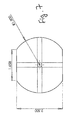
- FIGS. 2A and 2B illustrate different views of an embodiment of the bottom plate 105 of the inventive bicycle rack assembly.
- FIGS. 3A and 3B illustrate different views of an embodiment of the top plate 106 of the inventive bicycle rack assembly.
- FIGS. 4A and 4B illustrate different views of an embodiment of the internal vertical pole 102 of the inventive bicycle rack assembly.
- FIGS. 5A and 5B illustrate different views of an embodiment of the external vertical pole 102 of the inventive bicycle rack assembly.
- FIG. 6 illustrates an embodiment of the knob 107 of the inventive bicycle rack assembly.
- FIG. 7 illustrates an embodiment of the connector 103 of the inventive bicycle rack assembly.
- FIGS. 8A and 8B illustrate different views of an embodiment of the bracket 113 of the inventive bicycle rack assembly.
- FIGS. 9A and 9B illustrate different views of an embodiment of the bracket 114 of the inventive bicycle rack assembly.
- FIG. 10 illustrates another embodiment of the inventive bicycle rack assembly.
- the inventive assembly can be extended to a desired height by adding successive sections.
- section C is operationally position within at least a portion of section Z and can be extended from one side of the section Z to a desired height.
- the height to which the section C can be extended is adjusted by an adjustment mechanism (e.g. lever, squeezing wheel, etc.).
- the adjustment mechanism functions to fix the position of the section C when it is turned to the right and allow movement of the section C within the section Z when it is turned to the left.
- any number of additional sections can be attached to the section C, thus extending the height of the inventive bicycle rack assembly.
- a length of each section to be added to section C can be selected to obtain a total desired height of the inventive assembly.
- a length of each section to be added to section C varies from 1 to 5 feet.
- the successive section(s) is (are) attached to the section C using any suitable attachment mechanism.
- the attachment mechanism to add successive section(s) can be spring nipple mechanism, show in FIG. 10 .
- an embodiment of a bicycle rack assembly can include at least a pole 1101 (which can be extruded) whose length can be adjusted, as desired, by adding or removing sections 1102 .
- the pole 1101 is operationally connected to a base 1108 that operationally rests on a based plate 1109 which can be placed on the ground, for example, in a garage.
- the pole 1101 is operationally connected to another base 1104 that operationally connected to a brace assembly 1105 , made from a brace place, a brace support post cap, and a brace threaded rod.
- a based plate 1109 which can be placed on the ground, for example, in a garage.
- the brace assembly 1105 is placed, for example, against a ceiling of the garage.
- the chain or rope travels within extruded channels 1103 inside the pole 1101 .
- the mechanism that moves the chain is operated by an electrical motor, operationally connected to either base 1104 or the base 1108 .
- at least one block 1106 is operationally linked to the moving chain and moves up and down.
- the block 1106 is connected to a hanger 1106 that supports at least one bike rack tube 1107 .
- an embodiment of a bicycle rack assembly includes at least one pulley 1201 , flat mount, galvanized iron, about 13 ⁇ 8 inches outer diameter having about 5/16 inch rope.
- the embodiment of the bicycle rack assembly further includes at least one pulley 1202 , flat mount, galvanized steel, about 2 inch outer diameter, having about 1 ⁇ 4 inch rope.
- the embodiment of the bicycle rack assembly further includes at least one spring pin 1203 , slotted, about 3/16 inch diameter, about 1 inch length, made from 18-8 SS material.
- the embodiment of the bicycle rack assembly further includes at least one retaining ring 1204 , E-style, external, having about 1 ⁇ 2 inch shaft.
- the embodiment of the bicycle rack assembly further includes at least one gasket 1205 , a brace plate. In one example, the embodiment of the bicycle rack assembly further includes at least one gasket 1206 , a bike rack tube. In one example, the embodiment of the bicycle rack assembly further includes at least one main extrusion rail 1207 , about 8 feet. In one example, the embodiment of the bicycle rack assembly further includes at least one extension extrusion rail 1208 , about 1 foot. In one example, the embodiment of the bicycle rack assembly further includes at least one extension extrusion rail 1209 , about 2 feet. In one example, the embodiment of the bicycle rack assembly further includes at least one support beam 1210 , in form of 2 inch ⁇ 2 inch tube.
- the embodiment of the bicycle rack assembly further includes at least one brace plate 1211 . In one example, the embodiment of the bicycle rack assembly further includes at least one brace support post cap 1212 . In one example, the embodiment of the bicycle rack assembly further includes at least one brace threaded rod 1213 . In one example, the embodiment of the bicycle rack assembly further includes at least one base plate 1214 . In one example, the embodiment of the bicycle rack assembly further includes at least one block link bracket 1215 . In one example, the embodiment of the bicycle rack assembly further includes at least one fairlead hawse 1216 . In one example, the embodiment of the bicycle rack assembly further includes at least one base 1217 . In one example, the embodiment of the bicycle rack assembly further includes at least one block 1218 .
- the embodiment of the bicycle rack assembly further includes at least one block receiver 1219 . In one example, the embodiment of the bicycle rack assembly further includes at least one bike rack weldment 1220 . In one example, the embodiment of the bicycle rack assembly further includes at least one eyebolt 1221 , #10-32 ⁇ , 3 ⁇ 4 inch shank long. In one example, the embodiment of the bicycle rack assembly further includes at least one hex bolt 1222 , /4 inch-20 ⁇ 2.75 inch length. In one example, the embodiment of the bicycle rack assembly further includes k-locks 1223 - 1224 . In one example, the embodiment of the bicycle rack assembly further includes a plurality of screws 1225 - 1232 .
- the embodiment of the bicycle rack assembly further includes a plurality of washers 1233 - 1234 .
- the embodiment of the bicycle rack assembly further includes at least one switch 1235 , heavy-duty snap action, lever with roller actuator.
- the embodiment of the bicycle rack assembly further includes at least one clip bearing 1236 , 1 ⁇ 2 inch internal diameter and 0.138 tall.
- the embodiment of the bicycle rack assembly further includes at least one hoist 1237 , having specification of 120V, 60 Hz, 110 lb., single-220 dbl, and 0.08 wire rope.
- the embodiment of the bicycle rack assembly further includes at least one cap plug 1238 .
- the instant invention includes a bicycle rack assembly that consists of at least the following components: a first member having a first and a second ends; a second member having a first and a second ends, wherein the first member telescopically advances within and out of an inside cavity of the second member through the first end of the second member so that the first end of the first member moves within the inside cavity of the second member and the second end of the first member is positioned outside of the inside cavity of the second member; a first member securing assembly, wherein the first member securing assembly is operationally: 1) connected to the second end of the first member, and 2) attached to at least one first side of a structure within which the bicycle rack assembly is placed; a second member securing assembly, wherein the second member securing assembly is operationally: 1) connected to the second end of the second member, and 2) attached to at least one second side of the structure within which the bicycle rack assembly is placed; and a bicycle pulling assembly having a first part and a second part, wherein the first part of bicycle pulling
- the at least one first side of the structure and the at least one second side of the structure are at least two side walls of the structure. In some embodiments, the at least one first side of the structure is a ceiling of the structure and the at least one second side of the structure is a floor of the structure.
- the bicycle pulling assembly is operationally connected to at least one mechanical pulling device that causes the at least one movable cable to move between the first part and the second part of bicycle pulling assembly. In some embodiments, the bicycle pulling assembly is operationally connected to at least one pneumatic pulling device that causes the at least one movable cable to move between the first part and the second part of bicycle pulling assembly. In some embodiments, the bicycle pulling assembly is operationally connected to at least one electrically-driven pulling device that causes the at least one movable cable to move between the first part and the second part of bicycle pulling assembly.
- the first member securing assembly further includes a plate that is operationally connected to the second end of the first member at a bottom side of the plate; a pin having a first and a send ends, wherein the first end of the pin is operationally connected to a top side of the plate and wherein the second end of the pin extends away from the top side of the plate; and a knob that is operationally: 1) connected to the second end of the pin, and 2) attached to the at least one first side of the structure within which the bicycle rack assembly is placed.
- a length of first member is operationally adjusted by adding or removing at least one first section. In some embodiments, the at least one first section is added to or removed from the first member by employing at least one spring nipple mechanism. In some embodiments, a length of second member is operationally adjusted by adding or removing at least one second section. In some embodiments, the at least one second section is added to or removed from the second member by employing at least one second spring nipple mechanism.
- the inventive bicycle rack assembly can further consist of: at least one adjustment mechanism that is operationally connected to the first and the second members, wherein the at least one adjustment mechanism having a first operational state and a second operational state, wherein, in the first operational state, the at least one adjustment mechanism fixes the advancement of the first member within the inside cavity of the second member at a first position, and wherein, in the second operational state, the at least one adjustment mechanism allows the advancement of the first member within the inside cavity of the second member.
- the at least one adjustment mechanism is a lever.
- the instant invention includes a bicycle rack assembly that consists of at least the following components: a member having a first and a second ends; a first securing assembly, wherein the first securing assembly is operationally: 1) connected to the first end of the member, and 2) attached to at least one first side of a structure within which the bicycle rack assembly is placed; a second securing assembly, wherein the second securing assembly is operationally: 1) connected to the second end of the member, and 2) attached to at least one second side of the structure within which the bicycle rack assembly is placed; and a bicycle pulling assembly having a first part and a second part, wherein the first part of bicycle pulling assembly is operationally connected to the first securing assembly and the second part of bicycle pulling assembly is operationally connected to the second securing assembly, and wherein the bicycle pulling assembly that at least includes: 1) at least one movable cable that moves between the first part and the second part of bicycle pulling assembly, and 2) at least one hanger that is operationally connected to the at least one movable cable, where
Abstract
A bicycle rack assembly that includes a member; a first securing assembly, where the first securing assembly is operationally connected to the member; a second securing assembly, where the second securing assembly is operationally connected to the member; and a bicycle pulling assembly having a first part and a second part, where the first part is operationally connected to the first securing assembly and the second part is operationally connected to the second securing assembly; and where the bicycle pulling assembly includes a movable cable and a hanger that is operationally connected to the cable, where a plurality of bicycles are attached to the hanger so that the plurality of bicycles can be moved between the first part and the second part of bicycle pulling assembly while being hanged on the bicycle rack assembly.
Description
This application claims the benefit of U.S. provisional application Ser. No. 61/370,045, entitled “A VERTICAL BIKE RACK ASSEMBLY AND METHODS OF USE THEREOF,” was filed Aug. 2, 2010, which is hereby incorporated by reference herein in its entirety for all purposes.
The present invention relates to assemblies for storing bicycles (bikes).
Between uses, bicycles can be hanged individually from a wall of a garage or a house, placed against the wall, laid on the ground, or fixed upright position using a kickstand.
In some embodiments, the instant invention includes a bicycle rack assembly that consists of at least the following components: a first member having a first and a second ends; a second member having a first and a second ends, wherein the first member telescopically advances within and out of an inside cavity of the second member through the first end of the second member so that the first end of the first member moves within the inside cavity of the second member and the second end of the first member is positioned outside of the inside cavity of the second member; a first member securing assembly, wherein the first member securing assembly is operationally: 1) connected to the second end of the first member, and 2) attached to at least one first side of a structure within which the bicycle rack assembly is placed; a second member securing assembly, wherein the second member securing assembly is operationally: 1) connected to the second end of the second member, and 2) attached to at least one second side of the structure within which the bicycle rack assembly is placed; and a bicycle pulling assembly having a first part and a second part, wherein the first part of bicycle pulling assembly is operationally connected to the first member securing assembly and the second part of bicycle pulling assembly is operationally connected to the second member securing assembly, and wherein the bicycle pulling assembly that at least includes: 1) at least one movable cable that moves between the first part and the second part of bicycle pulling assembly, and 2) at least one hanger that is operationally connected to the at least one movable cable, wherein a plurality of bicycles are attached to the at least one hanger so that the plurality of bicycles can be moved between the first part and the second part of bicycle pulling assembly while being hanged on the bicycle rack assembly.
In some embodiments, the at least one first side of the structure and the at least one second side of the structure are at least two side walls of the structure. In some embodiments, the at least one first side of the structure is a ceiling of the structure and the at least one second side of the structure is a floor of the structure.
In some embodiments, the bicycle pulling assembly is operationally connected to at least one mechanical pulling device that causes the at least one movable cable to move between the first part and the second part of bicycle pulling assembly.
In some embodiments, the bicycle pulling assembly is operationally connected to at least one pneumatic pulling device that causes the at least one movable cable to move between the first part and the second part of bicycle pulling assembly.
In some embodiments, the bicycle pulling assembly is operationally connected to at least one electrically-driven pulling device that causes the at least one movable cable to move between the first part and the second part of bicycle pulling assembly.
In some embodiments, the first member securing assembly further includes a plate that is operationally connected to the second end of the first member at a bottom side of the plate; a pin having a first and a send ends, wherein the first end of the pin is operationally connected to a top side of the plate and wherein the second end of the pin extends away from the top side of the plate; and a knob that is operationally: 1) connected to the second end of the pin, and 2) attached to the at least one first side of the structure within which the bicycle rack assembly is placed.
In some embodiments, a length of first member is operationally adjusted by adding or removing at least one first section. In some embodiments, the at least one first section is added to or removed from the first member by employing at least one spring nipple mechanism. In some embodiments, a length of second member is operationally adjusted by adding or removing at least one second section. In some embodiments, the at least one second section is added to or removed from the second member by employing at least one second spring nipple mechanism.
In some embodiments, the inventive bicycle rack assembly can further consist of: at least one adjustment mechanism that is operationally connected to the first and the second members, wherein the at least one adjustment mechanism having a first operational state and a second operational state, wherein, in the first operational state, the at least one adjustment mechanism fixes the advancement of the first member within the inside cavity of the second member at a first position, and wherein, in the second operational state, the at least one adjustment mechanism allows the advancement of the first member within the inside cavity of the second member. In some embodiments, the at least one adjustment mechanism is a lever.
In some embodiments, the instant invention includes a bicycle rack assembly that consists of at least the following components: a member having a first and a second ends; a first securing assembly, wherein the first securing assembly is operationally: 1) connected to the first end of the member, and 2) attached to at least one first side of a structure within which the bicycle rack assembly is placed; a second securing assembly, wherein the second securing assembly is operationally: 1) connected to the second end of the member, and 2) attached to at least one second side of the structure within which the bicycle rack assembly is placed; and a bicycle pulling assembly having a first part and a second part, wherein the first part of bicycle pulling assembly is operationally connected to the first securing assembly and the second part of bicycle pulling assembly is operationally connected to the second securing assembly, and wherein the bicycle pulling assembly that at least includes: 1) at least one movable cable that moves between the first part and the second part of bicycle pulling assembly, and 2) at least one hanger that is operationally connected to the at least one movable cable, wherein a plurality of bicycles are attached to the at least one hanger so that the plurality of bicycles can be moved between the first part and the second part of bicycle pulling assembly while being hanged on the bicycle rack assembly.
The figures constitute a part of this specification and include illustrative embodiments of the present invention and illustrate various objects and features thereof. Further, the figures are not necessarily to scale, some features may be exaggerated to show details of particular components. In addition, any measurements, specifications and the like shown in the figures are intended to be illustrative, and not restrictive. Therefore, specific structural and functional details disclosed herein are not to be interpreted as limiting, but merely as a representative basis for teaching one skilled in the art to variously employ the present invention.
Among those benefits and improvements that have been disclosed, other objects and advantages of this invention will become apparent from the following description taken in conjunction with the accompanying figures. Detailed embodiments of the present invention are disclosed herein; however, it is to be understood that the disclosed embodiments are merely illustrative of the invention that may be embodied in various forms. In addition, each of the examples given in connection with the various embodiments of the invention which are intended to be illustrative, and not restrictive.
In one example, as shown in FIGS. 1A-1B , a bicycle rack assembly can include at least an external vertical pole 101 and an internal vertical pole 102. In one example, the pole 102 is operatively positioned within the pole 101 in manner that allows pole 102 to move within the inner cavity of the pole 101 and also to extend from at least one side to the pole 101 in a telescopic fashion. In one example, the poles 101 and 102 have correspondingly similar cross-sections (e.g. square, circular, or other). In one example, the poles 101 and 102 have correspondingly different cross-sections.
In one example, the pole 102 extends from the pole 101 for a desirable distance up to almost full length of the pole 102, while the poles 101 and 102 are stably secured to each other. In one example, the pole 102 extends from the pole 101 for a desirable distance with an assistance from a mechanical device, such as squeezing wheel. In one example, the pole 102 extends from the pole 101 for a desirable distance with an assistance from a pneumatic device, such as air compressor. In one example, the pole 102 extends from the pole 101 for a desirable distance with an assistance from a device driven by electrical force.
In one example, the vertical pole 102 is operationally connected to the top plate 106 through a bracket 113. In one example, the vertical pole 101 is operationally connected to the bottom plate 105 through a bracket 114.
In one example, the inventive assembly includes at least one connector 103 on which at least one bicycle can be operationally hanged. In one example, the connector 103 has at least one hanger 104 to which at least one bicycle is attached. In one example, at least one bicycle is attached to the at least one hanger 104 by way of a strap. In one example, the at least one hanger 104 has a hook-like shape on which the least one bicycle is hanged.
In one example, the pole 101 can be operationally connected to a bottom plate 105. In one example, the pole 102 is operationally connected to a bottom side of a top plate 106. In one example, there is knob 107 that includes a pin 107 a extending from the a top side of the top plate 106 and ending in a head 108. In one example, when the invention bicycle rack is installed, the head 108 presses, for example, against a ceiling, thus providing additional rigidity to the bicycle rack assembly. In one example, a height of the pin 107 a of the knob 107 is adjusted to provide tight attachment of the inventive assembly to ceiling.
In one example, the invention assembly includes a pulling mechanism that facilities the pulling of the hanged bicycles up along the bicycle rack assembly. In one example, as shown in FIGS. 1A and 1B , the pulling mechanism includes at least a pulley 109 which is operationally connected to the bottom side of the top plate 106. In one example, the pulling mechanism further includes an electrical motor 110, positioned on the top side of the bottom plate 105. In one example, the at least one connector 103 is operationally connected to the motor 110 by cable(s) 111 through the pulley 109. In one example, during an operation of the inventive assembly, at least one bicycle is attached to connector 103 at the hanger 104. In one example, during the operation, as the connector 103 being pulled up along the inventive assembly, ears 103 b on sides of the connector 103 slide along the cable(s) 111.
In one example, when there are at least two connectors 103, the connectors are connected to each other, for example, by a cable (112) attached to extensions 103 a of the successive connectors, thus allowing to increase more bicycles to be hanged on the inventive assembly. In one example, the inventive bicycle rack assembly can be extended from 8 feet to 14 feet, by extending the internal vertical pole 102 and placing the pin 107 a of knob 107 to the desired height.
In one example, any number of additional sections (e.g. sections A, B, etc.) can be attached to the section C, thus extending the height of the inventive bicycle rack assembly. In one example, a length of each section to be added to section C can be selected to obtain a total desired height of the inventive assembly. In one example, a length of each section to be added to section C varies from 1 to 5 feet. In one example, the successive section(s) is (are) attached to the section C using any suitable attachment mechanism. In one example, the attachment mechanism to add successive section(s) can be spring nipple mechanism, show in FIG. 10 .
In one example, as shown in FIGS. 11A-11B , an embodiment of a bicycle rack assembly can include at least a pole 1101 (which can be extruded) whose length can be adjusted, as desired, by adding or removing sections 1102. In one example, at one end, the pole 1101 is operationally connected to a base 1108 that operationally rests on a based plate 1109 which can be placed on the ground, for example, in a garage. In one example, at the other end, the pole 1101 is operationally connected to another base 1104 that operationally connected to a brace assembly 1105, made from a brace place, a brace support post cap, and a brace threaded rod. rests on a based plate 1109 which can be placed on the ground, for example, in a garage. In one example, the brace assembly 1105 is placed, for example, against a ceiling of the garage. In one example, there is a mechanism that moves a chain or rope that travels inside the pole 1101 between the bases 1004 and 1108. In one example, the chain or rope travels within extruded channels 1103 inside the pole 1101. In one example, the mechanism that moves the chain is operated by an electrical motor, operationally connected to either base 1104 or the base 1108. In one example, at least one block 1106 is operationally linked to the moving chain and moves up and down. In one example, the block 1106 is connected to a hanger 1106 that supports at least one bike rack tube 1107.
In one example, as shown in FIG. 12 , an embodiment of a bicycle rack assembly includes at least one pulley 1201, flat mount, galvanized iron, about 1⅜ inches outer diameter having about 5/16 inch rope. In one example, the embodiment of the bicycle rack assembly further includes at least one pulley 1202, flat mount, galvanized steel, about 2 inch outer diameter, having about ¼ inch rope. In one example, the embodiment of the bicycle rack assembly further includes at least one spring pin 1203, slotted, about 3/16 inch diameter, about 1 inch length, made from 18-8 SS material. In one example, the embodiment of the bicycle rack assembly further includes at least one retaining ring 1204, E-style, external, having about ½ inch shaft. In one example, the embodiment of the bicycle rack assembly further includes at least one gasket 1205, a brace plate. In one example, the embodiment of the bicycle rack assembly further includes at least one gasket 1206, a bike rack tube. In one example, the embodiment of the bicycle rack assembly further includes at least one main extrusion rail 1207, about 8 feet. In one example, the embodiment of the bicycle rack assembly further includes at least one extension extrusion rail 1208, about 1 foot. In one example, the embodiment of the bicycle rack assembly further includes at least one extension extrusion rail 1209, about 2 feet. In one example, the embodiment of the bicycle rack assembly further includes at least one support beam 1210, in form of 2 inch×2 inch tube. In one example, the embodiment of the bicycle rack assembly further includes at least one brace plate 1211. In one example, the embodiment of the bicycle rack assembly further includes at least one brace support post cap 1212. In one example, the embodiment of the bicycle rack assembly further includes at least one brace threaded rod 1213. In one example, the embodiment of the bicycle rack assembly further includes at least one base plate 1214. In one example, the embodiment of the bicycle rack assembly further includes at least one block link bracket 1215. In one example, the embodiment of the bicycle rack assembly further includes at least one fairlead hawse 1216. In one example, the embodiment of the bicycle rack assembly further includes at least one base 1217. In one example, the embodiment of the bicycle rack assembly further includes at least one block 1218. In one example, the embodiment of the bicycle rack assembly further includes at least one block receiver 1219. In one example, the embodiment of the bicycle rack assembly further includes at least one bike rack weldment 1220. In one example, the embodiment of the bicycle rack assembly further includes at least one eyebolt 1221, #10-32×, ¾ inch shank long. In one example, the embodiment of the bicycle rack assembly further includes at least one hex bolt 1222, /4 inch-20×2.75 inch length. In one example, the embodiment of the bicycle rack assembly further includes k-locks 1223-1224. In one example, the embodiment of the bicycle rack assembly further includes a plurality of screws 1225-1232. In one example, the embodiment of the bicycle rack assembly further includes a plurality of washers 1233-1234. In one example, the embodiment of the bicycle rack assembly further includes at least one switch 1235, heavy-duty snap action, lever with roller actuator. In one example, the embodiment of the bicycle rack assembly further includes at least one clip bearing 1236, ½ inch internal diameter and 0.138 tall. In one example, the embodiment of the bicycle rack assembly further includes at least one hoist 1237, having specification of 120V, 60 Hz, 110 lb., single-220 dbl, and 0.08 wire rope. In one example, the embodiment of the bicycle rack assembly further includes at least one cap plug 1238.
In some embodiments, the instant invention includes a bicycle rack assembly that consists of at least the following components: a first member having a first and a second ends; a second member having a first and a second ends, wherein the first member telescopically advances within and out of an inside cavity of the second member through the first end of the second member so that the first end of the first member moves within the inside cavity of the second member and the second end of the first member is positioned outside of the inside cavity of the second member; a first member securing assembly, wherein the first member securing assembly is operationally: 1) connected to the second end of the first member, and 2) attached to at least one first side of a structure within which the bicycle rack assembly is placed; a second member securing assembly, wherein the second member securing assembly is operationally: 1) connected to the second end of the second member, and 2) attached to at least one second side of the structure within which the bicycle rack assembly is placed; and a bicycle pulling assembly having a first part and a second part, wherein the first part of bicycle pulling assembly is operationally connected to the first member securing assembly and the second part of bicycle pulling assembly is operationally connected to the second member securing assembly, and wherein the bicycle pulling assembly that at least includes: 1) at least one movable cable that moves between the first part and the second part of bicycle pulling assembly, and 2) at least one hanger that is operationally connected to the at least one movable cable, wherein a plurality of bicycles are attached to the at least one hanger so that the plurality of bicycles can be moved between the first part and the second part of bicycle pulling assembly while being hanged on the bicycle rack assembly.
In some embodiments, the at least one first side of the structure and the at least one second side of the structure are at least two side walls of the structure. In some embodiments, the at least one first side of the structure is a ceiling of the structure and the at least one second side of the structure is a floor of the structure.
In some embodiments, the bicycle pulling assembly is operationally connected to at least one mechanical pulling device that causes the at least one movable cable to move between the first part and the second part of bicycle pulling assembly. In some embodiments, the bicycle pulling assembly is operationally connected to at least one pneumatic pulling device that causes the at least one movable cable to move between the first part and the second part of bicycle pulling assembly. In some embodiments, the bicycle pulling assembly is operationally connected to at least one electrically-driven pulling device that causes the at least one movable cable to move between the first part and the second part of bicycle pulling assembly.
In some embodiments, the first member securing assembly further includes a plate that is operationally connected to the second end of the first member at a bottom side of the plate; a pin having a first and a send ends, wherein the first end of the pin is operationally connected to a top side of the plate and wherein the second end of the pin extends away from the top side of the plate; and a knob that is operationally: 1) connected to the second end of the pin, and 2) attached to the at least one first side of the structure within which the bicycle rack assembly is placed.
In some embodiments, a length of first member is operationally adjusted by adding or removing at least one first section. In some embodiments, the at least one first section is added to or removed from the first member by employing at least one spring nipple mechanism. In some embodiments, a length of second member is operationally adjusted by adding or removing at least one second section. In some embodiments, the at least one second section is added to or removed from the second member by employing at least one second spring nipple mechanism.
In some embodiments, the inventive bicycle rack assembly can further consist of: at least one adjustment mechanism that is operationally connected to the first and the second members, wherein the at least one adjustment mechanism having a first operational state and a second operational state, wherein, in the first operational state, the at least one adjustment mechanism fixes the advancement of the first member within the inside cavity of the second member at a first position, and wherein, in the second operational state, the at least one adjustment mechanism allows the advancement of the first member within the inside cavity of the second member. In some embodiments, the at least one adjustment mechanism is a lever.
In some embodiments, the instant invention includes a bicycle rack assembly that consists of at least the following components: a member having a first and a second ends; a first securing assembly, wherein the first securing assembly is operationally: 1) connected to the first end of the member, and 2) attached to at least one first side of a structure within which the bicycle rack assembly is placed; a second securing assembly, wherein the second securing assembly is operationally: 1) connected to the second end of the member, and 2) attached to at least one second side of the structure within which the bicycle rack assembly is placed; and a bicycle pulling assembly having a first part and a second part, wherein the first part of bicycle pulling assembly is operationally connected to the first securing assembly and the second part of bicycle pulling assembly is operationally connected to the second securing assembly, and wherein the bicycle pulling assembly that at least includes: 1) at least one movable cable that moves between the first part and the second part of bicycle pulling assembly, and 2) at least one hanger that is operationally connected to the at least one movable cable, wherein a plurality of bicycles are attached to the at least one hanger so that the plurality of bicycles can be moved between the first part and the second part of bicycle pulling assembly while being hanged on the bicycle rack assembly.
While the above-identified drawings set forth presently disclosed embodiments, other embodiments are also contemplated, as noted in the discussion. This disclosure presents illustrative embodiments by way of representation and not limitation. Numerous other modifications and embodiments can be devised by those skilled in the art which fall within the scope and spirit of the principles of the presently disclosed invention.
Claims (18)
1. A bicycle rack assembly, comprising:
a first member having a first and a second ends;
a second member having a first and a second ends, wherein the first member telescopically advances within and out of an inside cavity of the second member through the first end of the second member so that the first end of the first member moves within the inside cavity of the second member and the second end of the first member is positioned outside of the inside cavity of the second member;
a first member securing assembly, wherein the first member securing assembly is operationally:
1) connected to the second end of the first member, and
2) attached to at least one first side of a structure within which the bicycle rack assembly is placed;
a second member securing assembly, wherein the second member securing assembly is operationally:
1) connected to the second end of the second member, and
2) attached to at least one second side of the structure within which the bicycle rack assembly is placed; and
a bicycle pulling assembly having a first part and a second part, wherein the first part of bicycle pulling assembly is operationally connected to the first member securing assembly and the second part of bicycle pulling assembly is operationally connected to the second member securing assembly, and wherein the bicycle pulling assembly, comprising:
1) at least one movable cable that moves between the first part and the second part of the bicycle pulling assembly,
2) a first hanger that is operationally connected to the at least one movable cable, and
3) a second hanger that is operationally connected to the at least one movable cable; and
wherein each of the first hanger and the second hanger are configured to hang a plurality of bicycles;
wherein the plurality of bicycles are attached to at least one of the first hanger or the second hanger so that the plurality of bicycles can be moved between the first part and the second part of the bicycle pulling assembly while being hanged on the bicycle rack assembly.
2. The bicycle rack assembly of claim 1 , wherein the at least one first side of the structure and the at least one second side of the structure are at least two side walls of the structure.
3. The bicycle rack assembly of claim 1 , wherein the at least one first side of the structure is a ceiling of the structure and the at least one second side of the structure is a floor of the structure.
4. The bicycle rack assembly of claim 1 , wherein the bicycle pulling assembly is operationally connected to at least one mechanical pulling device that causes the at least one movable cable to move between the first part and the second part of bicycle pulling assembly.
5. The bicycle rack assembly of claim 1 , wherein the bicycle pulling assembly is operationally connected to at least one pneumatic pulling device that causes the at least one movable cable to move between the first part and the second part of bicycle pulling assembly.
6. The bicycle rack assembly of claim 1 , wherein the bicycle pulling assembly is operationally connected to at least one electrically-driven pulling device that causes the at least one movable cable to move between the first part and the second part of bicycle pulling assembly.
7. The bicycle rack assembly of claim 1 , wherein the first member securing assembly further comprising:
a plate that is operationally connected to the second end of the first member at a bottom side of the plate;
a pin having a first and a send ends, wherein the first end of the pin is operationally connected to a top side of the plate and wherein the second end of the pin extends away from the top side of the plate; and
a knob that is operationally:
1) connected to the second end of the pin, and
2) attached to the at least one first side of the structure within which the bicycle rack assembly is placed.
8. The bicycle rack assembly of claim 1 , wherein a length of first member is operationally adjusted by adding or removing at least one first section.
9. The bicycle rack assembly of claim 1 , wherein a length of second member is operationally adjusted by adding or removing at least one second section.
10. The bicycle rack assembly of claim 1 , wherein the bicycle rack assembly further comprising:
at least one adjustment mechanism that is operationally connected to the first and the second members, wherein the at least one adjustment mechanism having a first operational state and a second operational state, wherein, in the first operational state, the at least one adjustment mechanism fixes the advancement of the first member within the inside cavity of the second member at a first position, and wherein, in the second operational state, the at least one adjustment mechanism allows the advancement of the first member within the inside cavity of the second member.
11. The bicycle rack assembly of claim 10 , wherein the at least one adjustment mechanism is a lever.
12. A bicycle rack assembly, comprising:
a member having a first and a second ends;
a first securing assembly, wherein the first securing assembly is operationally:
1) connected to the first end of the member, and
2) attached to at least one first side of a structure within which the bicycle rack assembly is placed;
a second securing assembly, wherein the second securing assembly is operationally:
1) connected to the second end of the member, and
2) attached to at least one second side of the structure within which the bicycle rack assembly is placed; and
a bicycle pulling assembly having a first part and a second part, wherein the first part of bicycle pulling assembly is operationally connected to the first securing assembly and the second part of bicycle pulling assembly is operationally connected to the second securing assembly, and wherein the bicycle pulling assembly, comprising:
1) at least one movable cable that moves between the first part and the second part of the bicycle pulling assembly,
2) a first hanger that is operationally connected to the at least one movable cable, and
3) a second hanger that is operationally connected to the at least one movable cable; and
wherein each of the first hanger and the second hanger are configured to hang a plurality of bicycles;
wherein the plurality of bicycles are attached to at least one of the first hanger or the second hanger so that the plurality of bicycles can be moved between the first part and the second part of the bicycle pulling assembly while being hanged on the bicycle rack assembly.
13. The bicycle rack assembly of claim 12 , wherein the at least one first side of the structure and the at least one second side of the structure are at least two side walls of the structure.
14. The bicycle rack assembly of claim 12 , wherein the at least one first side of the structure is a ceiling of the structure and the at least one second side of the structure is a floor of the structure.
15. The bicycle rack assembly of claim 12 , wherein the bicycle pulling assembly is operationally connected to at least one mechanical pulling device that causes the at least one movable cable to move between the first part and the second part of bicycle pulling assembly.
16. The bicycle rack assembly of claim 12 , wherein the bicycle pulling assembly is operationally connected to at least one pneumatic pulling device that causes the at least one movable cable to move between the first part and the second part of bicycle pulling assembly.
17. The bicycle rack assembly of claim 12 , wherein the bicycle pulling assembly is operationally connected to at least one electrically-driven pulling device that causes the at least one movable cable to move between the first part and the second part of bicycle pulling assembly.
18. The bicycle rack assembly of claim 12 , wherein a length of the member is operationally adjusted by adding or removing at least one section.
Priority Applications (2)
| Application Number | Priority Date | Filing Date | Title |
|---|---|---|---|
| US13/196,609 US8893898B2 (en) | 2010-08-02 | 2011-08-02 | Bicycle rack assembly and methods of use thereof |
| US13/472,034 US9004295B2 (en) | 2010-08-02 | 2012-05-15 | Equipment rack assembly and methods of use thereof |
Applications Claiming Priority (2)
| Application Number | Priority Date | Filing Date | Title |
|---|---|---|---|
| US37004510P | 2010-08-02 | 2010-08-02 | |
| US13/196,609 US8893898B2 (en) | 2010-08-02 | 2011-08-02 | Bicycle rack assembly and methods of use thereof |
Related Child Applications (1)
| Application Number | Title | Priority Date | Filing Date |
|---|---|---|---|
| US13/472,034 Continuation-In-Part US9004295B2 (en) | 2010-08-02 | 2012-05-15 | Equipment rack assembly and methods of use thereof |
Publications (2)
| Publication Number | Publication Date |
|---|---|
| US20120024802A1 US20120024802A1 (en) | 2012-02-02 |
| US8893898B2 true US8893898B2 (en) | 2014-11-25 |
Family
ID=45525641
Family Applications (1)
| Application Number | Title | Priority Date | Filing Date |
|---|---|---|---|
| US13/196,609 Expired - Fee Related US8893898B2 (en) | 2010-08-02 | 2011-08-02 | Bicycle rack assembly and methods of use thereof |
Country Status (4)
| Country | Link |
|---|---|
| US (1) | US8893898B2 (en) |
| EP (1) | EP2600754A1 (en) |
| CN (1) | CN103188967B (en) |
| WO (1) | WO2012018842A1 (en) |
Cited By (2)
| Publication number | Priority date | Publication date | Assignee | Title |
|---|---|---|---|---|
| US11058022B1 (en) * | 2019-09-10 | 2021-07-06 | Luis Ross | Vertical track and sliding mount for a smoke detector |
| US11731719B2 (en) | 2020-02-12 | 2023-08-22 | Hurricane Merchants LLC | Telescoping ceiling mounted storage or bike rack |
Families Citing this family (4)
| Publication number | Priority date | Publication date | Assignee | Title |
|---|---|---|---|---|
| US9004295B2 (en) | 2010-08-02 | 2015-04-14 | Edward Dovner | Equipment rack assembly and methods of use thereof |
| US20140339182A1 (en) * | 2013-05-19 | 2014-11-20 | InVinity Wine System LLC | Rack system for wine bottles and the like |
| CN105293365B (en) * | 2015-11-13 | 2017-12-15 | 嘉兴市日丰金属制品有限公司 | Bicycle suspension device |
| US11407623B2 (en) * | 2018-10-20 | 2022-08-09 | Bary Sanford BOGGESS | Configurable lift system |
Citations (13)
| Publication number | Priority date | Publication date | Assignee | Title |
|---|---|---|---|---|
| US3770133A (en) * | 1972-02-11 | 1973-11-06 | Miller E | Bicycle storage device |
| US4552270A (en) * | 1984-03-01 | 1985-11-12 | Lentz Scott B | Storage system for athletic equipment or the like |
| US5086930A (en) * | 1990-03-21 | 1992-02-11 | Ford Saeks | Storage system for holding athletic equipment and a method |
| US5183162A (en) * | 1991-05-10 | 1993-02-02 | Robert Ritzenthaler | Mobile mount system |
| US5294006A (en) * | 1992-10-13 | 1994-03-15 | Deschino Robert M | Bicycle rack apparatus |
| US5772048A (en) * | 1996-04-22 | 1998-06-30 | Sopcisak; Michael Ivan | Quick-release bicycle stand |
| US5845788A (en) * | 1997-03-19 | 1998-12-08 | Rhc/Spacemaster Corporation | Bicycle storage and display system |
| US6095344A (en) * | 1998-01-07 | 2000-08-01 | White; Kenneth D. | Overhead storage system |
| US6164459A (en) * | 1999-01-21 | 2000-12-26 | Liem; Ken | Coin operated bicycle locking rack |
| US6637602B2 (en) * | 2002-01-29 | 2003-10-28 | Raymond Dueck | Display rack for storing and displaying articles |
| US20070029267A1 (en) * | 2005-08-08 | 2007-02-08 | Hall David D | Bicycle support rack |
| US7434674B1 (en) * | 2004-03-22 | 2008-10-14 | Bain Charles E | Dispensing system for a wheeled device |
| US8437873B2 (en) * | 2009-02-08 | 2013-05-07 | Perry North | Automated bike parking system |
Family Cites Families (4)
| Publication number | Priority date | Publication date | Assignee | Title |
|---|---|---|---|---|
| US5800294A (en) * | 1997-03-21 | 1998-09-01 | Naecker, Jr.; Charles A. | Mobile hoop hitch |
| US6161702A (en) * | 1999-02-12 | 2000-12-19 | Campbell; Dale R. | Lifting system for bicycle storage and methods using the same |
| US6820842B1 (en) * | 2003-05-01 | 2004-11-23 | Louis Chuang | Telescopic support |
| US7806308B2 (en) * | 2006-09-14 | 2010-10-05 | Midwest Bus Corporation | Releasable mounting of bicycle rack on vehicle bumper |
-
2011
- 2011-08-02 WO PCT/US2011/046301 patent/WO2012018842A1/en active Application Filing
- 2011-08-02 EP EP11815214.9A patent/EP2600754A1/en not_active Withdrawn
- 2011-08-02 US US13/196,609 patent/US8893898B2/en not_active Expired - Fee Related
- 2011-08-02 CN CN201180038151.0A patent/CN103188967B/en not_active Expired - Fee Related
Patent Citations (13)
| Publication number | Priority date | Publication date | Assignee | Title |
|---|---|---|---|---|
| US3770133A (en) * | 1972-02-11 | 1973-11-06 | Miller E | Bicycle storage device |
| US4552270A (en) * | 1984-03-01 | 1985-11-12 | Lentz Scott B | Storage system for athletic equipment or the like |
| US5086930A (en) * | 1990-03-21 | 1992-02-11 | Ford Saeks | Storage system for holding athletic equipment and a method |
| US5183162A (en) * | 1991-05-10 | 1993-02-02 | Robert Ritzenthaler | Mobile mount system |
| US5294006A (en) * | 1992-10-13 | 1994-03-15 | Deschino Robert M | Bicycle rack apparatus |
| US5772048A (en) * | 1996-04-22 | 1998-06-30 | Sopcisak; Michael Ivan | Quick-release bicycle stand |
| US5845788A (en) * | 1997-03-19 | 1998-12-08 | Rhc/Spacemaster Corporation | Bicycle storage and display system |
| US6095344A (en) * | 1998-01-07 | 2000-08-01 | White; Kenneth D. | Overhead storage system |
| US6164459A (en) * | 1999-01-21 | 2000-12-26 | Liem; Ken | Coin operated bicycle locking rack |
| US6637602B2 (en) * | 2002-01-29 | 2003-10-28 | Raymond Dueck | Display rack for storing and displaying articles |
| US7434674B1 (en) * | 2004-03-22 | 2008-10-14 | Bain Charles E | Dispensing system for a wheeled device |
| US20070029267A1 (en) * | 2005-08-08 | 2007-02-08 | Hall David D | Bicycle support rack |
| US8437873B2 (en) * | 2009-02-08 | 2013-05-07 | Perry North | Automated bike parking system |
Cited By (2)
| Publication number | Priority date | Publication date | Assignee | Title |
|---|---|---|---|---|
| US11058022B1 (en) * | 2019-09-10 | 2021-07-06 | Luis Ross | Vertical track and sliding mount for a smoke detector |
| US11731719B2 (en) | 2020-02-12 | 2023-08-22 | Hurricane Merchants LLC | Telescoping ceiling mounted storage or bike rack |
Also Published As
| Publication number | Publication date |
|---|---|
| EP2600754A1 (en) | 2013-06-12 |
| CN103188967A (en) | 2013-07-03 |
| WO2012018842A1 (en) | 2012-02-09 |
| US20120024802A1 (en) | 2012-02-02 |
| CN103188967B (en) | 2015-12-16 |
Similar Documents
| Publication | Publication Date | Title |
|---|---|---|
| US9004295B2 (en) | Equipment rack assembly and methods of use thereof | |
| US8893898B2 (en) | Bicycle rack assembly and methods of use thereof | |
| US6095344A (en) | Overhead storage system | |
| CN108758165B (en) | Steering reducing pipeline robot | |
| CN104909202A (en) | Supporting device for cables | |
| JP2016007960A (en) | Bicycle parking device | |
| CN203609032U (en) | Space variable wardrobe | |
| CN205035001U (en) | Generator handling device | |
| CN206505677U (en) | A kind of new city road traffic street lamp intelligent steering Sign Board | |
| CN103510967B (en) | Telescopic jib and concrete sprayer | |
| CN202788598U (en) | Connecting rod type hidden cat ladder | |
| JP2014161364A (en) | Exercise device for upper half of body | |
| CN220487467U (en) | Climbing device for security construction | |
| CN212058581U (en) | Street lamp pole support arm diameter measuring device based on stay cord range finding | |
| CN209762888U (en) | Lamp post device used for stage and capable of stretching up and down | |
| CN211040879U (en) | Street lamp pole protection architecture | |
| CN220410391U (en) | Lighting vehicle | |
| CN215528510U (en) | Adjustable carriage of power line | |
| CN203564692U (en) | Game flying ring | |
| KR20100022333A (en) | Structure for a signal lamp | |
| JP5106175B2 (en) | Guide tool for leading material of wiring tool during cable drawing work | |
| CN201258223Y (en) | Three upright post flat beam type hoist | |
| CN209336570U (en) | Universal ride with laser navigation | |
| CN202644958U (en) | Adjustable parapet wall supporting and suspending device | |
| CN201902237U (en) | Portable metal support |
Legal Events
| Date | Code | Title | Description |
|---|---|---|---|
| FEPP | Fee payment procedure |
Free format text: MAINTENANCE FEE REMINDER MAILED (ORIGINAL EVENT CODE: REM.) |
|
| LAPS | Lapse for failure to pay maintenance fees |
Free format text: PATENT EXPIRED FOR FAILURE TO PAY MAINTENANCE FEES (ORIGINAL EVENT CODE: EXP.); ENTITY STATUS OF PATENT OWNER: SMALL ENTITY |
|
| STCH | Information on status: patent discontinuation |
Free format text: PATENT EXPIRED DUE TO NONPAYMENT OF MAINTENANCE FEES UNDER 37 CFR 1.362 |
|
| FP | Expired due to failure to pay maintenance fee |
Effective date: 20181125 |