US8892706B1 - Private ethernet overlay networks over a shared ethernet in a virtual environment - Google Patents
Private ethernet overlay networks over a shared ethernet in a virtual environment Download PDFInfo
- Publication number
- US8892706B1 US8892706B1 US12/819,438 US81943810A US8892706B1 US 8892706 B1 US8892706 B1 US 8892706B1 US 81943810 A US81943810 A US 81943810A US 8892706 B1 US8892706 B1 US 8892706B1
- Authority
- US
- United States
- Prior art keywords
- packet
- host
- vnic
- network
- private
- Prior art date
- Legal status (The legal status is an assumption and is not a legal conclusion. Google has not performed a legal analysis and makes no representation as to the accuracy of the status listed.)
- Active, expires
Links
- 238000000034 method Methods 0.000 claims abstract description 40
- 238000004590 computer program Methods 0.000 claims abstract description 13
- 230000005540 biological transmission Effects 0.000 claims abstract description 7
- 230000006855 networking Effects 0.000 claims description 20
- 238000009434 installation Methods 0.000 claims description 9
- 238000002955 isolation Methods 0.000 claims 1
- 238000005538 encapsulation Methods 0.000 description 17
- 230000008569 process Effects 0.000 description 8
- 239000012634 fragment Substances 0.000 description 7
- 238000007726 management method Methods 0.000 description 6
- 238000012360 testing method Methods 0.000 description 6
- 238000012545 processing Methods 0.000 description 5
- 238000001914 filtration Methods 0.000 description 4
- 238000013467 fragmentation Methods 0.000 description 4
- 238000006062 fragmentation reaction Methods 0.000 description 4
- 238000010367 cloning Methods 0.000 description 2
- 238000013500 data storage Methods 0.000 description 2
- 230000001419 dependent effect Effects 0.000 description 2
- 238000010586 diagram Methods 0.000 description 2
- 238000001152 differential interference contrast microscopy Methods 0.000 description 2
- 230000003287 optical effect Effects 0.000 description 2
- 230000004044 response Effects 0.000 description 2
- 230000008859 change Effects 0.000 description 1
- 239000003795 chemical substances by application Substances 0.000 description 1
- 238000004891 communication Methods 0.000 description 1
- 238000011161 development Methods 0.000 description 1
- 238000005516 engineering process Methods 0.000 description 1
- 238000009432 framing Methods 0.000 description 1
- 238000013507 mapping Methods 0.000 description 1
- 230000007246 mechanism Effects 0.000 description 1
- 238000012986 modification Methods 0.000 description 1
- 230000004048 modification Effects 0.000 description 1
- 230000008520 organization Effects 0.000 description 1
- 238000011112 process operation Methods 0.000 description 1
- 238000012549 training Methods 0.000 description 1
- 238000012546 transfer Methods 0.000 description 1
Images


Classifications
-
- H—ELECTRICITY
- H04—ELECTRIC COMMUNICATION TECHNIQUE
- H04L—TRANSMISSION OF DIGITAL INFORMATION, e.g. TELEGRAPHIC COMMUNICATION
- H04L69/00—Network arrangements, protocols or services independent of the application payload and not provided for in the other groups of this subclass
- H04L69/22—Parsing or analysis of headers
-
- H—ELECTRICITY
- H04—ELECTRIC COMMUNICATION TECHNIQUE
- H04L—TRANSMISSION OF DIGITAL INFORMATION, e.g. TELEGRAPHIC COMMUNICATION
- H04L12/00—Data switching networks
- H04L12/28—Data switching networks characterised by path configuration, e.g. LAN [Local Area Networks] or WAN [Wide Area Networks]
- H04L12/46—Interconnection of networks
- H04L12/4641—Virtual LANs, VLANs, e.g. virtual private networks [VPN]
-
- H—ELECTRICITY
- H04—ELECTRIC COMMUNICATION TECHNIQUE
- H04L—TRANSMISSION OF DIGITAL INFORMATION, e.g. TELEGRAPHIC COMMUNICATION
- H04L12/00—Data switching networks
- H04L12/28—Data switching networks characterised by path configuration, e.g. LAN [Local Area Networks] or WAN [Wide Area Networks]
- H04L12/46—Interconnection of networks
- H04L12/4633—Interconnection of networks using encapsulation techniques, e.g. tunneling
-
- H—ELECTRICITY
- H04—ELECTRIC COMMUNICATION TECHNIQUE
- H04L—TRANSMISSION OF DIGITAL INFORMATION, e.g. TELEGRAPHIC COMMUNICATION
- H04L45/00—Routing or path finding of packets in data switching networks
- H04L45/44—Distributed routing
-
- H—ELECTRICITY
- H04—ELECTRIC COMMUNICATION TECHNIQUE
- H04L—TRANSMISSION OF DIGITAL INFORMATION, e.g. TELEGRAPHIC COMMUNICATION
- H04L45/00—Routing or path finding of packets in data switching networks
- H04L45/66—Layer 2 routing, e.g. in Ethernet based MAN's
-
- H—ELECTRICITY
- H04—ELECTRIC COMMUNICATION TECHNIQUE
- H04L—TRANSMISSION OF DIGITAL INFORMATION, e.g. TELEGRAPHIC COMMUNICATION
- H04L49/00—Packet switching elements
- H04L49/70—Virtual switches
Definitions
- the present invention relates to methods, systems, and computer programs for deploying fenced groups of Virtual Machines (VMs) in a virtual infrastructure, and more particularly, to methods, systems, and computer programs for private networking among fenced groups of VMs executing in multiple hosts of the virtual infrastructure.
- VMs Virtual Machines
- Virtualization of computer resources generally involves abstracting computer hardware, which essentially isolates operating systems and applications from underlying hardware. Hardware is therefore shared among multiple operating systems and applications wherein each operating system and its corresponding applications are isolated in corresponding VMs and wherein each VM is a complete execution environment. As a result, hardware can be more efficiently utilized.
- the virtualization of computer resources sometimes requires the virtualization of networking resources.
- To create a private network in a virtual infrastructure means that a set of virtual machines have exclusive access to this private network.
- virtual machines can be located in multiple hosts that may be connected to different physical networks. Trying to impose a private network on a distributed environment encompassing multiple physical networks is a complex problem.
- sending a broadcast message in a private network presents two problems. First, the broadcast may be received by hosts which do not host any VMs in the private network, thus reducing the scalability of the entire distributed system. Second, if hosts are not located on adjacent layer 2 networks, the broadcast may not reach all hosts with VMs in the private network.
- VLAN Virtual Local Area Networks
- a VLAN is a group of hosts that communicate as if the group of hosts were attached to the Broadcast domain, regardless of their physical location.
- a VLAN has the same attributes as a physical Local Area Network (LAN), but the VLAN allows for end stations to be grouped together even if the end stations are not located on the same network switch. Network reconfiguration can be done through software instead of by physically relocating devices.
- Routers in VLAN topologies provide broadcast filtering, security, address summarization, and traffic flow management. However, VLANs only offer encapsulation and, by definition, switches may not bridge traffic between VLANs as it would violate the integrity of the VLAN broadcast domain. Further, VLANs are not easily programmable by a centralized virtual infrastructure manager.
- Virtual labs such as VMware's vCenter Lab ManagerTM from the assignee of the present patent application, enable application development and test teams to create and deploy complex multi-tier system and network configurations on demand quickly. Testing engineers can set up, capture, and reset virtual machine configurations for demonstration environments in seconds. In addition, hands-on labs can be quickly configured and deployed for lab testing, hands-on training classes, etc.
- the creation of virtual lab environments requires flexible tools to assist in the creation and management of computer networks. For example, if a test engineer decides to perform different tests simultaneously on one sample environment, the test engineer must deploy multiple times the sample environment. The multiple deployments must coexist in the virtual infrastructure. However, these environments often have network configurations that when deployed multiple times would cause networking routing problems, such as the creation of VMs with duplicate Internet Protocol (IP) addresses—an impermissible network scenario for the proper operation of the VMs and of the virtual lab environments.
- IP Internet Protocol
- a method includes an operation for sending a packet on a private virtual network from a first virtual machine (VM) in a first host to a second VM.
- the first and second VMs are members of a fenced group of computers that have exclusive direct access to the private virtual network, where VMs outside the fenced group do not have direct access to the packets that travel on the private virtual network.
- the method includes encapsulating the packet at the first host to include a new header as well as a fence identifier for the fenced group. The packet is received at a host where the second VM is executing and the packet is de-encapsulated to extract the new header and the fence identifier.
- the method includes an operation for delivering the de-encapsulated packet to the second VM after validating that the destination address in the packet and the fence identifier correspond to the destination address and the fence identifier, respectively, of the second VM.
- a computer program embedded in a non-transitory computer-readable storage medium when executed by one or more processors, for implementing private networking within a virtual infrastructure, includes program instructions for sending a packet on a private virtual network from a first VM in a first host to a second VM.
- the first and second VMs are members of a fenced group of computers that have exclusive direct access to the private virtual network, where VMs outside the fenced group do not have direct access to packets on the private virtual network.
- the computer program includes program instructions for encapsulating the packet at the first host to include a new header and a fence identifier for the fenced group, and for receiving the packet at a host where the second VM is executing.
- the computer includes program instructions for de-encapsulating the packet to extract the new header and the fence identifier, and program instructions for delivering the de-encapsulated packet to the second VM after validating that a destination address in the packet and the fence identifier correspond to the second VM.
- a system for private networking within a virtual infrastructure includes a first VM and a first filter in a first host, in addition to a second VM and a second filter in a second host.
- the first and second VMs are members of a fenced group of computers that have exclusive direct access to a private virtual network, where VMs outside the fenced group do not have direct access to packets on the private virtual network.
- the first filter encapsulates a packet sent on a private virtual network from the first VM, by adding to the packet a new header and a fence identifier for the fenced group.
- the second filter de-encapsulates the packet to extract the new header and the fence identifier, and the second filter delivers the de-encapsulated packet to the second VM after validating that a destination address in the packet and the fence identifier correspond to the second VM.
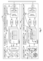
- FIG. 1 includes an architectural diagram of an embodiment of a virtual infrastructure system.
- FIG. 2 depicts one embodiment of the host architecture for instantiating Virtual Machines (VM) with multiple Virtual Network Interface Cards (VNIC).
- VM Virtual Machines
- VNIC Virtual Network Interface Cards
- FIG. 3 illustrates the deployment of multiple VM configurations, according to one embodiment.
- FIG. 4 illustrates the use of packet filters within the host, according to one embodiment.
- FIG. 5 shows one embodiment for Ethernet frame encapsulation.
- FIG. 6 provides a detailed illustration of the encapsulated packet, in accordance with one embodiment of the invention.
- FIG. 7 illustrates the flow of a broadcast packet sent within the private virtual network, according to one embodiment.
- FIG. 8 illustrates the flow of the response packet to the broadcast, according to one embodiment.
- FIG. 9A illustrates the flow of a packet travelling between VMs in the same host, according to one embodiment.
- FIG. 9B illustrates the flow of an Internet Protocol (IP) packet, according to one embodiment.
- IP Internet Protocol
- FIG. 10 illustrates the update of bridge tables when a VM migrates to a different host, according to one embodiment.
- FIG. 11 shows the structure of a Maximum Transmission Unit (MTU) configuration table, according to one embodiment.
- MTU Maximum Transmission Unit
- FIG. 12 shows one embodiment of an active-ports table.
- FIG. 13 shows an embodiment of a bridge table.
- FIG. 14 shows the process flow of a method for private networking within a virtual infrastructure, in accordance with one embodiment of the invention.
- Embodiments of the invention use Media Access Control (MAC) encapsulation of Ethernet packets.
- the hosts that include Virtual Machines (VM) from fenced groups of machines implement distributed switching with learning for unicast delivery. As a result, VMs are allowed to migrate to other hosts to enable resource management and High Availability (HA). Further, the private network implementation is transparent to the guest operating system (GOS) in the VMs and provides an added level of privacy.
- GOS guest operating system
- VMs can be placed on any host where the private network is implemented.
- the HSPN may span hosts in a cluster or clusters in a datacenter, allowing large groups of VMs to communicate over the private network. Additionally, VMs may move between hosts since VMs maintain private network connectivity. A VM can also be powered-on in a different host after failover and still retain network connectivity. Further, VMs get their own isolated private level 2 connectivity without the need to obtain Virtual Local Area Networks (VLAN) ID resources or even setup VLANs. Creating a HSPN is therefore simpler because there is no dependency on the network administrator.
- the HSPN can be deployed on either a VLAN or an Ethernet segment.
- Ethernet Internet Protocol
- TCP Transmission Control Protocol
- OSI Open Systems Interconnection
- FIG. 1 includes an architectural diagram of an embodiment of a virtual infrastructure system.
- Virtual infrastructure 102 includes one or more virtual infrastructure servers 104 that manage a plurality of hosts 106 .
- Virtual machines 108 are instantiated in hosts 106 , and the multiple hosts share a plurality of resources within the virtual infrastructure, such as shared storage 110 .
- a configuration is a core element of a virtual lab and is composed of virtual machines and virtual lab networks. Virtual lab users can group, deploy, save, share, and monitor multi-machine configurations. Configurations reside in the library or in user workspaces, in which case they are referred to as workspace configurations.
- Many applications run on more than one machine and grouping machines in one configuration is more convenient to manage the applications.
- the database server may run on one machine, the application server on another machine, and the client on a third machine. All these machines would be configured to run with each other.
- Other servers may execute related applications, such as LDAP servers, Domain Name servers, domain controllers, etc.
- Virtual lab server allows the grouping of these dependent machines into a Configuration, which can be checked in and out of the library. When a configuration is checked out, all the dependent machines configured to work with each other are activated at the same time. Library configurations can also store the running state of machines so the deployment of machines that are already running is faster.
- Virtual lab networks can be categorized as private networks and shared networks.
- Private networks in a configuration are those networks available exclusively to VMs in the configuration, that is, only VMs in the configuration can have a Network Interface Controller (NIC) or VNIC connected directly to a switch or virtual switch (VSwitch) for the private network. Access to data on a private network is restricted to members of the configuration, that is, the private network is isolated from other entities outside the configuration.
- a private network in the configuration can be connected to a physical network to provide external connectivity to the VMs in the private network.
- Private networks in a configuration are also referred to herein as Configuration Local Networks (CLN) or virtual networks.
- CLN Configuration Local Networks
- Shared networks also referred to herein as shared physical networks or physical networks, are available to all VMs in the virtual infrastructure, which means that a configuration including a shared network will enable VMs in the shared network to communicate with other VMs in the virtual infrastructure connected, directly or indirectly, to the shared network.
- a shared network is part of a Virtual Local Area Network (VLAN).
- VLAN Virtual Local Area Network
- Deploying a configuration causes the VMs and networks in the configuration to be instantiated in the virtual infrastructure.
- Instantiating the VMs includes registering the VMs in the virtual infrastructure and powering-on the VMs.
- virtual lab deploys all shared networks and CLNs associated with the configuration using the network connectivity options in the configuration.
- Undeploying a configuration de-instantiates the VMs in the configuration from the virtual infrastructure.
- De-instantiating VMs includes powering off or suspending the VMs and un-registering the VMs from the virtual infrastructure. The state of the deployment can be saved in storage or discarded. Saving the memory state helps debugging memory-specific issues and makes VMs in the configuration ready for deployment and use almost instantly.
- Virtual lab server 112 manages and deploys virtual machine configurations in a collection of hosts 106 . It should be appreciated that not all hosts 106 need to be part of the scope of virtual lab server 112 , although in one embodiment, all the hosts are within the scope of virtual lab server 112 .
- Virtual lab server 112 manages hosts 106 by communicating with virtual infrastructure server 104 , and by using virtual lab server agents installed on those hosts. In one embodiment, virtual lab server 112 communicates with virtual infrastructure server 104 via an Application Programming Interface (API), for example, to request the instantiation of VMs and networks.
- API Application Programming Interface
- virtual lab server 112 is used to perform some management tasks on hosts 106 , the continuous presence of virtual lab server 112 is not required for the normal operation of deployed VMs, which can continue to run even if virtual lab server 112 becomes unreachable, for example because a network failure.
- One or more users 116 interface with virtual lab server 112 and virtual infrastructure 102 via a computer interface, which in one embodiment is performed via web browser.
- FIG. 2 depicts one embodiment of the host architecture for instantiating VMs with multiple Virtual Network Interface Cards (VNIC).
- VMkernel 204 also referred to as virtual infrastructure layer, manages the assignment of VMs 206 in host 202 .
- VM 206 includes Guest Operating System (GOS) 208 and multiple VNICs 210 .
- Each VNIC 210 is connected to a VSwitch 212 that provides network switch functionality for the corresponding virtual network interfaces.
- VSwitches 212 are connected to a physical NIC device in the host to provide access to physical network 216 .
- Each of the VNICs and VSwitches are independent, thus a VM can connect to several virtual networks via several VNICs that connect to one or more physical NIC devices 214 .
- each VSwitch 212 is connected to a different physical NIC device, thus each VSwitch 212 provides connectivity to a different physical network.
- VSwitch 212 provides switching for virtual networks “Network 1” (VNIC1) and “Network 4” (VNIC4).
- VNIC1 virtual networks
- VNIC4 virtual networks
- VSwitch 212 assigns a set of ports to “Network 1” and a different set of ports to “Network 4,” where each set of ports supports Media Access Control (MAC) addressing for the corresponding virtual network.
- MAC Media Access Control
- the virtual computer system supports VM 206 .
- system hardware 220 includes one or more processors (CPUs) 222 , which may be a single processor, or two or more cooperating processors in a known multiprocessor arrangement.
- the system hardware also includes system memory 226 , one or more disks 228 , and some form of Memory Management Unit (MMU) 224 .
- the system memory is typically some form of high-speed RAM (random access memory), whereas the disk is typically a non-volatile, mass storage device.
- the system hardware also includes, or is connected to, conventional registers, interrupt handling circuitry, a clock, etc., which, for the sake of simplicity, are not shown in the figure.
- the system software includes VMKernel 204 , which has drivers for controlling and communicating with various devices 230 , NICs 214 , and disk 228 .
- VM 206 the physical system components of a “real” computer are emulated in software, that is, they are virtualized.
- VM 206 will typically include virtualized guest OS 208 and virtualized system hardware (not shown), which in turn includes one or more virtual CPUs, virtual system memory, one or more virtual disks, one or more virtual devices, etc., all of which are implemented in software to emulate the corresponding components of an actual computer.
- the guest OS 208 may, but need not, simply be a copy of a conventional, commodity OS.
- the interface between VM 103 and the underlying host hardware 220 is responsible for executing VM related instructions and for transferring data to and from the actual physical memory 226 , the processor(s) 222 , the disk(s) 228 and other devices.
- FIG. 3 illustrates the deployment of multiple VM configurations, according to one embodiment.
- Configuration 302 which includes VMs A, B, and C, is deployed a first time resulting in deployment 304 .
- the system performs the copying, also referred to as cloning, in a short amount of time, taking a fraction of the disk space a normal copy would take. This is referred to as linked clones.
- cloning in a short amount of time, taking a fraction of the disk space a normal copy would take.
- linked clones For example, when a virtual lab server VM with an 80 GB disk, is cloned, the 80 GB are not copied. Instead a 16 MB file called a linked clone is created, which points to the 80 GB disk and acts like a new instance of the disk.
- Virtual lab server Another feature of virtual lab server is the ability to use multiple copies of VMs simultaneously, without modifying them. When machines are copied using traditional techniques, the original and the copy cannot be used simultaneously due to duplicate IP addresses, MAC addresses, and security IDs (in the case of Windows). Virtual lab server provides a networking technology called “fencing” that allows multiple unchanged copies of virtual lab server VMs to be run simultaneously on the same network without conflict, while still allowing the VMs to access network resources and be accessed remotely.
- FIG. 3 illustrates the process of deploying fenced VMs.
- the first deployment 304 can use the IP and Ethernet addresses in configuration 302 and be directly connected to the network without any conflicts (of course assuming no other VMs in the network have the same addresses).
- Deployment 306 is created after cloning the first deployment 304 . However, deployment 306 cannot be connected directly to the network because there would be duplicate addresses on the network.
- Deployment 308 is deployed in fenced mode, including private networking module 310 , which performs, among other things, filtering and encapsulation of network packets before sending the packets on the physical network. This way, there is no duplication of addresses in the physical network.
- FIG. 4 illustrates the use of packet filters within host 402 , according to one embodiment.
- Host 402 includes several VMs. Each VM is associated with a VNIC 404 .
- each VM only has one network connection, which means one VNIC.
- VNIC network interface controller
- Principles of the invention can also be applied when a VM has multiple VNICs, because the important consideration is that each VNIC be associated with one layer 2 and one layer 3 address. Therefore, it would be more precise to refer to VNICs instead of VMs, but for ease of description VMs are used in the description of some embodiments. However, it is understood that if a VM has more than one VNIC, then each VNIC would be separately considered and belonging to a separate private network.
- a Distributed Virtual (DV) Filter 408 is associated with VNIC 404 and performs filtering and encapsulation of packets originating in VNIC 404 before the packets reach distributed vSwitch 410 .
- DV Filter 408 performs filtering and de-encapsulation (stripping) when needed.
- Distributed vSwitch 410 is connected to one or more physical NICs (PNIC) 412 that connect host 402 to physical network 414 .
- PNIC physical NICs
- DV Filter 408 enables the implementation of the cross-host private virtual network.
- the DV filter is compatible with VLAN and other overlays solutions as the encapsulation performed by DV Filter 408 is transparent to switches and routers on the network. More details on the operation of DV Filter 408 are given below in reference to FIGS. 7-13 .
- FIG. 5 shows one embodiment for Ethernet frame encapsulation.
- a packet sent from a VM in the private virtual network includes original Ethernet header 506 and original payload 508 .
- the DV Filter adds a new header and new data to the original packet.
- the encapsulation Ethernet header 502 has the standard fields of an Ethernet header. More details on the composition of encapsulation Ethernet header 502 are given below in reference to FIG. 6 .
- DV Filter also adds fence protocol data 504 to the data field of the new Ethernet packet in front of the original packet.
- the payload for the new packet includes fence protocol data 504 , original Ethernet header 506 , and original payload 508 .
- the new encapsulated packet includes additional bytes, it is possible that the resulting encapsulated packet exceeds the Maximum Transmission Unit (MTU) of layer 2.
- MTU Maximum Transmission Unit
- fragmentation is required.
- the encapsulated packet is fragmented in 2 different packets, transmitted separately, and the DV filter at the receiving host de-encapsulates the two packets by combining their contents to recreate the encapsulated packet.
- fragmentation is avoided by increasing the uplink MTU.
- the VM is configured by the user with an MTU that is smaller from the MTU on the network, such that encapsulation can be performed on all packets without fragmentation.
- the traffic of the private virtual network is isolated from other traffic, in the sense that the Ethernet headers of the private network packets are “hidden” from view.
- the private network packets terminate in hosts that implement the private networking, allowing an additional level of control and security. Switches and routers on the network do not see or have to deal with this encapsulation because they only see a standard Ethernet header, which is processed the same as any standard Ethernet header.
- no network infrastructure or additional resources are required to implement private networking, there no MAC addressing collisions, and VLANs are interoperable with the private virtual network scheme.
- a large number of private networks is possible (i.e. 16 million or more) per VLAN.
- FIG. 6 provides a detailed illustration of the encapsulated packet, in accordance with one embodiment of the invention.
- the encapsulating header includes a destination address, a source address and a time to live (T/L) field.
- the source and destination address are form by joining together a fence Organizationally-Unique-Identifier (OUI) (24 bits), an installation identifier (“Install ID”) (8 bits), and a host identifier (16 bits).
- UMI Organizationally-Unique-Identifier
- Install ID installation identifier
- An OUI is a 24-bit number that is purchased from the Institute of Electrical and Electronics Engineers, Incorporated (IEEE) Registration Authority.
- This identifier uniquely identifies a vendor, manufacturer, or other organization globally and effectively reserves a block of each possible type of derivative identifier (such as MAC addresses, group addresses, Subnetwork Access Protocol protocol identifiers, etc.) for the exclusive use of the assignee.
- derivative identifier such as MAC addresses, group addresses, Subnetwork Access Protocol protocol identifiers, etc.
- the fence OUI is a dedicated OUI reserved for private virtual networking. Therefore, there will not be address collisions on the network because nodes that are not part of the private networking scheme will not use the reserved fence OUI.
- the destination address in the encapsulating header can also be a broadcast address, and all the hosts in the network will receive this packet.
- the virtual lab server installation ID is unique on a LAN segment and is managed by virtual lab server 112 ( FIG. 1 ).
- the fence identifier uniquely identifies a private network within the virtual lab server. Fence IDs can be recycled over time.
- the T/L field in the encapsulating header includes the fence Ethernet type which is an IEEE assigned number (in this case assigned to VMware, the assignee of the present application) that identifies the protocol carried by the Ethernet frame. More specifically, the protocol identified is the Fence protocol, i.e., the protocol to perform MAC-in-MAC framing. The Ethernet type is used to distinguish one protocol from another.
- the fence protocol data includes a version ID of the private network implementation or protocol (2 bits), a fragment type (2 bits), a fragment sequence number, and a fence identifier.
- the fragment type and sequence number indicate if the original packet has been fragmented, and if so, which fragment number corresponds to the packet.
- the fence identifier indicates a value assigned to the private virtual network. In one embodiment, this field is 24 bits which allows for more than 16 million different private networks per real LAN.
- FIGS. 5 and 6 are exemplary data fields for encapsulating network packets. Other embodiments may utilize different fields, or may arrange the data in varying manners. The embodiments illustrated in FIGS. 5 and 6 should therefore not be interpreted to be exclusive or limiting, but rather exemplary or illustrative.
- FIG. 7 illustrates the flow of a broadcast packet sent within the private virtual network, according to one embodiment.
- FIG. 7 illustrates some of the events that take place after VM A 720 is initialized.
- VM A 720 sends a broadcast Address Resolution Protocol (ARP) packet 702 to be delivered to all nodes that have layer-2 connectivity on the private network associated with Fence 1.
- ARP broadcast Address Resolution Protocol
- Fence 1 includes VM A 720 in Host 1 714 and VM B 742 in Host 2 716 .
- VM B 744 also in Host 2 716 , is a clone of VM B 742 and is connected to a different private network from the one connected to VMA 720 and VM B 742 .
- Packet 702 is a standard ARP broadcast packet including VM A's address as the source address.
- VM A 720 sends the message through port 722 , which is associated with Fence 1.
- DV Filter 724 receives packet 704 , associated with Fence 1, and adds the encapsulating header, as described above in reference to FIGS. 5 and 6 , to create encapsulated packet 706 .
- the destination address of the encapsulating header is also an Ethernet broadcast address.
- DV Filter 724 sends packet 706 to distributed vSwitch 726 for transmittal over the network via physical NIC 728 .
- Host 2 716 receives packet 706 (referred to as packet 708 ) and the Distributed vSwitch forwards packet 708 to the DV Filters for all VNICS, since it is a broadcast packet.
- DV Filter 734 associated with VM B 742 examines the source address. It determines that packet 708 is a private virtual network packet because of the unique fence OUI. This packet comes from Host 1 because the source address includes Host 1's ID and it is originally from VM A because VM A's Ethernet address is in the original Ethernet header. Since DV Filter 734 did not have an entry for VM A in that private network, an entry is added to bridge table 746 mapping VM A with Host 1. More details on the structure of bridge table 746 are given below in reference to FIG. 13 .
- DV Filter 734 de-encapsulates the packet by stripping the encapsulating headers and added data to create packet 710 , which is associated with Fence 1 as indicated in the Fence ID of the fence protocol data. DV Filter then checks for ports associated with Fence 1 and the destination address of packet 710 , which is every node since it is a broadcast address. Since VM 742 is associated with Fence 1 738 , packet 712 is delivered to VM B 742 . On the other hand, VM B 744 will not get delivery of the packet or frame because the DV Filter for VM B 744 (not shown) will detect that the frame is for Fence 1 nodes and will drop the frame because VM B 744 does not belong to Fence 1. It belongs to Fence 2.
- this mechanism provides an added level of security by assuring that the fence is isolated. Packets that have no Fence ID will be dropped and will never make it inside the fence.
- FIG. 8 illustrates the flow of the response packet to the broadcast, according to one embodiment.
- VM B 742 replies to packet 712 with packet 802 addressed to VM A 720 .
- DV Filter 734 receives packet 804 , associated with Fence 1 because VM B's port is associated with Fence 1.
- DV Filter 734 checks bridge table 746 and finds an entry for VM A indicating that VM A is executing in Host 1.
- DV Filter proceeds to create new Ethernet packet 806 by encapsulating packet 804 .
- the addresses in the encapsulation header are created according to the process described in reference to FIG. 6 . For example, the destination Ethernet address is constructed by combining the fence OUI (24 bits), the installation identifier (8 bits), and the number associated with Host 1 (16 bits).
- the fence ID for Fence 1 is added after the header and before the original packet, as previously described.
- Host 1 receives packet 808 , which is processed in similar fashion as described in reference to FIG. 7 , except that the destination address is not a broadcast address.
- DV Filter 724 determines that the packet is from VM B in Fence 1. Since there is not an entry for VM B in bridge table 814 , a new entry for VM B is added to bridge table 814 indicating that VM B is executing in Host 2. Additionally, DV Filter 724 proceeds to strip packet 808 to restore original packet 802 sent by VM B 74 , by taking out the added header and the additional payload ahead of the original packet.
- packet 810 which is associated with Fence 1 because the payload in packet 808 indicates that the packet is for a Fence 1 node. Since VM A's port is associated with Fence 1 722 and the Ethernet destination address, packet 812 is successfully delivered to VM A 720 .
- FIG. 9A illustrates the flow of a packet travelling between VMs in the same host, according to one embodiment.
- Packet 902 is sent from VM A 920 with a destination address of VM C 928 , with both VMs executing in the same host.
- the process is similar as the one previously described in FIGS. 7 and 8 , except that the packet does not travel over the physical network and is “turned around” by Distributed VSwitch 926 .
- packet 902 is sent to VNIC 930 , which in turn sends packet 904 to DV Filter 922 .
- packets are described herein as travelling (sent and received) among the different entities of the chain of communication, it is not necessary to actually transfer the whole packet from one module to the next.
- a pointer to the message may be passed between VNIC 930 and DV filter without having to actually make a copy of the packet.
- DV filter for VM A 922 checks bridge table 924 and determines that the destination VM C is executing in Host 1. The corresponding encapsulation is performed to create packet 906 which is forwarded to distributed vSwitch 926 via output leaf 932 .
- VSwitch 926 determines that the destination address of packet 906 is for a VM inside the host and “turns the packet around” by forwarding packet 908 to the DV Filter for VM C (not shown) via input leaf 934 .
- the DV Filter for VM C strips the headers and, after checking the destination address and the Fence ID, delivers the packet to VM C's port in VNIC 930 .
- FIG. 9B illustrates the flow of an Internet Protocol (IP) packet, according to one embodiment.
- IP Internet Protocol
- FIG. 9B illustrates sending an IP packet from VM A 970 in Host 1 to VM B 972 in Host 2.
- the process is similar to the one described in FIG. 7 , except that there is not a broadcast address but instead a unicast address, and the bridge tables in the DV filters already have the pertinent entries as VMs A and B have been running for a period of time.
- IP Internet Protocol
- encapsulated packet 956 leaving DV Filter 974 , includes source and destination address associated with the IDs of hosts 1 and 2, respectively.
- DV Filter 976 for VM B receives packet 958 , it does not create a new entry in the bridge table because the entry for VM A already exists. Packet 958 is forwarded to VM B via the distributed switch and the VNIC port, as previously described.
- packet 952 is an Ethernet frame and that the scenario described in FIG. 9 is for VMs that are executing in hosts with layer 2 connectivity. If the destination VM were in a host executing in a different LAN segment (i.e., a different data link layer segment), then MAC in MAC encapsulation would not work because the packet would be sent to a router in the network which may not be aware of the private networking scheme for fencing and would not work properly as the IP header is not where the router would expect it. In this case other fencing solutions for hosts on different networks can be combined with embodiments of the inventions. Solutions for internetwork fencing are described in U.S.
- VLAN network can be used to provide layer-2 connectivity to hosts in different networks.
- FIG. 10 illustrates the update of bridge tables when a VM migrates to a different host, according to one embodiment.
- VM A 156 moves from Host 1 150 to Host 2 152 , VM A 156 sends a Reverse Address Resolution Protocol (RARP) packet 160 .
- RARP is a computer networking protocol used by a host computer to request its IP address from an administrative host, when the host computer has available its Link Layer or hardware address, such as a MAC address.
- packet 160 Since packet 160 is a broadcast packet, packet 160 will reach all nodes in the same private network as VM A 156 .
- packet 166 is received by DV Filter 172 in Host 2 154 , DV Filter 172 detects that message is from VM A in Host 3. Since the bridge table entry for VM A has Host 1 as the host for VM A, and the new packet indicates that VM A is now executing in Host 3, the entry for VM A in bridge table 174 is updated to reflect this change.
- the packet is then delivered to VM B 158 because VM B is part of the private network in Fence 1 and this is a broadcast packet.
- FIG. 11 shows the structure of an MTU configuration table, according to one embodiment.
- the MTU configuration table is used to store the MTU for each network.
- each entry (shown as columns in the table) includes a LAN identifier and a MTU for the corresponding LAN.
- each fragment is sent separately to the destination host with a different fragment sequence number.
- the DV filter at the destination will combine the fragments to reconstruct the original encapsulated packet.
- a way to avoid fragmentation is by reducing the MTU in the network configuration of the host. For example, if the MTU of a network is 1,500, the network can be configured in the VM as having an MTU of 1,336, reserving 144 bits for the encapsulation by the DV Filter.
- FIG. 12 shows one embodiment of an active-ports table.
- the active-ports table has one entry (in each row) for each active VNIC and includes an OPI field, a LAN ID, and the MTU.
- the OPI includes virtual lab server parameters “installation ID” and “fence ID”.
- the installation ID identifies a particular implementation of a fenced configuration, and different clones will have different fence IDs.
- the fence ID identifies the fence ID associated with the VNIC.
- the LAN ID is an internal identifier of the underlying network that the private network (fence) overlays. Different fences may share the underlying LAN.
- the MTU indicates the maximum transmission unit on the network.
- FIG. 13 shows an embodiment of a bridge table.
- the bridge table resides in the DV filter and is used to keep the address of the destination hosts where the VMs of the private network are executing.
- the network is organized by VNIC, also referred to as ports, each associated with the VNIC for a VM.
- VNIC also referred to as ports
- the example shown in FIG. 13 includes entries for 3 ports, 0x4100b9f869e0, 0x4100b9f86d40, and 0x4100b9f86f30.
- Port 0x4100b9f869e0 has no entries in the bridge table yet, and the other two ports have 4 entries.
- Each of these entries includes an inner MAC address, an outer MAC address, a “used” flag, an “age” value, and a “seen” flag.
- the inner MAC address corresponds to the Ethernet of another VM in the same private network.
- the outer MAC address corresponds to the Ethernet of the host that the VM is on and includes the address that would be added in an encapsulating header to send a message to the corresponding VM.
- the address may be constructed as described in reference to FIG. 6 .
- the entry in DV filter 746 of FIG. 7 holds the inner MAC address of VM A, and the outer MAC address for Host 1.
- the used flag indicates if the entry is being used, the age flag indicates if the entry has been updated in a predetermined period of time, and the seen flag indicates if the entry has been used recently.
- FIGS. 11-13 are interrelated.
- the second entry in active ports table of FIG. 2 is for port 0x4100b9f86d40.
- the OPI is “3e,0000fb”, which means that the installation ID is 3e and the fence ID is 0000fb.
- the bridge table of FIG. 13 it can be observed that outer MAC addresses for port 0x4100b9f86d40 have the same OUI (00:13:f5), and the same installation ID ( 3 e ).
- the remainder of the outer MAC address corresponds host IDs for different hosts (02:c2, 02:e2, 03:02, and 02:f2).
- FIG. 14 shows the process flow of a method for private networking within a virtual infrastructure, in accordance with one embodiment of the invention.
- the process includes operation 1402 for sending a packet on a private virtual network from a first VM in a first host.
- the first VM and a second VM are members of a fenced group of computers that have exclusive direct access to the private virtual network, such that VMs outside the fenced group do not have direct access to packets on the private virtual network.
- the method flows to operation 1404 for encapsulating the packet at the first host to include a new header and a fence identifier for the fenced group. See for example DV filter 724 of FIG. 7 .
- the packet is received at a host where the second VM is executing, in operation 1406 , and the method continues in operation 1408 for de-encapsulating the packet to extract the new header and the fence identifier.
- the de-encapsulated packet is delivered to the second VM after validating that the destination address in the packet and the fence identifier correspond to the address of the second VM and the fence identifier of the second VM.
- Embodiments of the present invention may be practiced with various computer system configurations including hand-held devices, microprocessor systems, microprocessor-based or programmable consumer electronics, minicomputers, mainframe computers and the like.
- the invention can also be practiced in distributed computing environments where tasks are performed by remote processing devices that are linked through a network.
- the invention can employ various computer-implemented operations involving data stored in computer systems. These operations are those requiring physical manipulation of physical quantities. Any of the operations described herein that form part of the invention are useful machine operations.
- the invention also relates to a device or an apparatus for performing these operations.
- the apparatus may be specially constructed for the required purpose, such as a special purpose computer.
- the computer can also perform other processing, program execution or routines that are not part of the special purpose, while still being capable of operating for the special purpose.
- the operations may be processed by a general purpose computer selectively activated or configured by one or more computer programs stored in the computer memory, cache, or obtained over a network. When data is obtained over a network the data maybe processed by other computers on the network, e.g., a cloud of computing resources.
- the invention can also be embodied as computer readable code on a computer readable medium.
- the computer readable medium is any data storage device that can store data, which can be thereafter be read by a computer system. Examples of the computer readable medium include hard drives, network attached storage (NAS), read-only memory, random-access memory, CD-ROMs, CD-Rs, CD-RWs, magnetic tapes and other optical and non-optical data storage devices.
- the computer readable medium can include computer readable tangible medium distributed over a network-coupled computer system so that the computer readable code is stored and executed in a distributed fashion.
Abstract
Description
Claims (18)
Priority Applications (5)
| Application Number | Priority Date | Filing Date | Title |
|---|---|---|---|
| US12/819,438 US8892706B1 (en) | 2010-06-21 | 2010-06-21 | Private ethernet overlay networks over a shared ethernet in a virtual environment |
| US14/546,787 US9900410B2 (en) | 2006-05-01 | 2014-11-18 | Private ethernet overlay networks over a shared ethernet in a virtual environment |
| US15/898,613 US10951744B2 (en) | 2010-06-21 | 2018-02-18 | Private ethernet overlay networks over a shared ethernet in a virtual environment |
| US17/200,801 US11838395B2 (en) | 2010-06-21 | 2021-03-13 | Private ethernet overlay networks over a shared ethernet in a virtual environment |
| US18/375,907 US20240031459A1 (en) | 2010-06-21 | 2023-10-02 | Private ethernet overlay networks over a shared ethernet in a virtual environment |
Applications Claiming Priority (1)
| Application Number | Priority Date | Filing Date | Title |
|---|---|---|---|
| US12/819,438 US8892706B1 (en) | 2010-06-21 | 2010-06-21 | Private ethernet overlay networks over a shared ethernet in a virtual environment |
Related Child Applications (1)
| Application Number | Title | Priority Date | Filing Date |
|---|---|---|---|
| US14/546,787 Division US9900410B2 (en) | 2006-05-01 | 2014-11-18 | Private ethernet overlay networks over a shared ethernet in a virtual environment |
Publications (1)
| Publication Number | Publication Date |
|---|---|
| US8892706B1 true US8892706B1 (en) | 2014-11-18 |
Family
ID=51870275
Family Applications (5)
| Application Number | Title | Priority Date | Filing Date |
|---|---|---|---|
| US12/819,438 Active 2031-09-05 US8892706B1 (en) | 2006-05-01 | 2010-06-21 | Private ethernet overlay networks over a shared ethernet in a virtual environment |
| US14/546,787 Active 2031-03-19 US9900410B2 (en) | 2006-05-01 | 2014-11-18 | Private ethernet overlay networks over a shared ethernet in a virtual environment |
| US15/898,613 Active 2030-10-18 US10951744B2 (en) | 2010-06-21 | 2018-02-18 | Private ethernet overlay networks over a shared ethernet in a virtual environment |
| US17/200,801 Active US11838395B2 (en) | 2010-06-21 | 2021-03-13 | Private ethernet overlay networks over a shared ethernet in a virtual environment |
| US18/375,907 Pending US20240031459A1 (en) | 2010-06-21 | 2023-10-02 | Private ethernet overlay networks over a shared ethernet in a virtual environment |
Family Applications After (4)
| Application Number | Title | Priority Date | Filing Date |
|---|---|---|---|
| US14/546,787 Active 2031-03-19 US9900410B2 (en) | 2006-05-01 | 2014-11-18 | Private ethernet overlay networks over a shared ethernet in a virtual environment |
| US15/898,613 Active 2030-10-18 US10951744B2 (en) | 2010-06-21 | 2018-02-18 | Private ethernet overlay networks over a shared ethernet in a virtual environment |
| US17/200,801 Active US11838395B2 (en) | 2010-06-21 | 2021-03-13 | Private ethernet overlay networks over a shared ethernet in a virtual environment |
| US18/375,907 Pending US20240031459A1 (en) | 2010-06-21 | 2023-10-02 | Private ethernet overlay networks over a shared ethernet in a virtual environment |
Country Status (1)
| Country | Link |
|---|---|
| US (5) | US8892706B1 (en) |
Cited By (59)
| Publication number | Priority date | Publication date | Assignee | Title |
|---|---|---|---|---|
| US20140122675A1 (en) * | 2012-10-29 | 2014-05-01 | Oracle International Corporation | Network virtualization over infiniband |
| US20140192804A1 (en) * | 2013-01-09 | 2014-07-10 | Dell Products L.P. | Systems and methods for providing multicast routing in an overlay network |
| US20140269709A1 (en) * | 2013-03-12 | 2014-09-18 | International Business Machines Corporation | Virtual gateways and implicit routing in distributed overlay virtual environments |
| US20140331221A1 (en) * | 2010-10-28 | 2014-11-06 | Yaozu Dong | Cooperated approach to network packet filtering |
| US20150071301A1 (en) * | 2006-05-01 | 2015-03-12 | Vmware, Inc. | Private ethernet overlay networks over a shared ethernet in a virtual environment |
| US20150100670A1 (en) * | 2013-10-04 | 2015-04-09 | International Business Machines Corporation | Transporting multi-destination networking traffic by sending repetitive unicast |
| US9112801B2 (en) | 2013-03-15 | 2015-08-18 | International Business Machines Corporation | Quantized congestion notification in a virtual networking system |
| US9143582B2 (en) | 2013-03-08 | 2015-09-22 | International Business Machines Corporation | Interoperability for distributed overlay virtual environments |
| US20150326474A1 (en) * | 2012-11-30 | 2015-11-12 | Hewlett-Packard Development Company | Path to host in response to message |
| US20150372917A1 (en) * | 2012-08-17 | 2015-12-24 | International Business Machines Corporation | Load balancing overlay network traffic using a teamed set of network interface cards |
| US20160028693A1 (en) * | 2014-07-28 | 2016-01-28 | Ge Intelligent Platforms, Inc. | Apparatus and method for security of industrial control networks |
| US9264384B1 (en) | 2004-07-22 | 2016-02-16 | Oracle International Corporation | Resource virtualization mechanism including virtual host bus adapters |
| US9331963B2 (en) | 2010-09-24 | 2016-05-03 | Oracle International Corporation | Wireless host I/O using virtualized I/O controllers |
| US9374241B2 (en) | 2013-03-14 | 2016-06-21 | International Business Machines Corporation | Tagging virtual overlay packets in a virtual networking system |
| US20160261496A1 (en) * | 2013-10-31 | 2016-09-08 | Hangzhou H3C Technologies Co., Ltd. | Packet forwarding in data center network |
| US9559951B1 (en) * | 2013-08-29 | 2017-01-31 | Cisco Technology, Inc. | Providing intra-subnet and inter-subnet data center connectivity |
| US9697032B2 (en) | 2009-07-27 | 2017-07-04 | Vmware, Inc. | Automated network configuration of virtual machines in a virtual lab environment |
| US9813283B2 (en) | 2005-08-09 | 2017-11-07 | Oracle International Corporation | Efficient data transfer between servers and remote peripherals |
| US9973446B2 (en) | 2009-08-20 | 2018-05-15 | Oracle International Corporation | Remote shared server peripherals over an Ethernet network for resource virtualization |
| US10031768B2 (en) * | 2015-06-30 | 2018-07-24 | Vmware, Inc. | Host-gateway-facilitated aggregation of host-computer clusters |
| US10114707B2 (en) * | 2013-06-28 | 2018-10-30 | EMC IP Holding Company LLC | Cross site recovery of a VM |
| US10164892B2 (en) * | 2013-12-31 | 2018-12-25 | Red Hat Israel, Ltd. | Overhead management for virtual machines |
| US20190028435A1 (en) * | 2017-07-20 | 2019-01-24 | Nicira, Inc. | Enhanced network processing of virtual node data packets |
| US10374937B2 (en) * | 2014-10-06 | 2019-08-06 | Ntt Docomo, Inc. | Domain control method and domain control device |
| US10417255B2 (en) | 2013-06-28 | 2019-09-17 | EMC IP Holding Company LLC | Metadata reconciliation |
| US10516568B2 (en) | 2014-09-30 | 2019-12-24 | Nicira, Inc. | Controller driven reconfiguration of a multi-layered application or service model |
| US10594743B2 (en) | 2015-04-03 | 2020-03-17 | Nicira, Inc. | Method, apparatus, and system for implementing a content switch |
| US10594604B1 (en) * | 2013-10-08 | 2020-03-17 | Juniper Networks, Inc. | End to end application identification and analytics of tunnel encapsulated traffic in the underlay |
| US10637800B2 (en) | 2017-06-30 | 2020-04-28 | Nicira, Inc | Replacement of logical network addresses with physical network addresses |
| US10659252B2 (en) | 2018-01-26 | 2020-05-19 | Nicira, Inc | Specifying and utilizing paths through a network |
| US10681000B2 (en) | 2017-06-30 | 2020-06-09 | Nicira, Inc. | Assignment of unique physical network addresses for logical network addresses |
| US10693782B2 (en) | 2013-05-09 | 2020-06-23 | Nicira, Inc. | Method and system for service switching using service tags |
| US10728146B1 (en) | 2019-02-26 | 2020-07-28 | International Business Machines Corporation | Virtual container dynamic virtual IP address |
| US10728174B2 (en) | 2018-03-27 | 2020-07-28 | Nicira, Inc. | Incorporating layer 2 service between two interfaces of gateway device |
| US10735319B1 (en) | 2019-02-26 | 2020-08-04 | International Business Machines Corporation | Virtual container extended network virtualization in server cluster |
| US10797910B2 (en) | 2018-01-26 | 2020-10-06 | Nicira, Inc. | Specifying and utilizing paths through a network |
| US10797966B2 (en) | 2017-10-29 | 2020-10-06 | Nicira, Inc. | Service operation chaining |
| US10805192B2 (en) | 2018-03-27 | 2020-10-13 | Nicira, Inc. | Detecting failure of layer 2 service using broadcast messages |
| US10929171B2 (en) | 2019-02-22 | 2021-02-23 | Vmware, Inc. | Distributed forwarding for performing service chain operations |
| US10944673B2 (en) | 2018-09-02 | 2021-03-09 | Vmware, Inc. | Redirection of data messages at logical network gateway |
| US10956287B2 (en) | 2018-09-18 | 2021-03-23 | International Business Machines Corporation | Failover mechanism with minimized packet losses |
| CN112769852A (en) * | 2021-01-20 | 2021-05-07 | 西门子工厂自动化工程有限公司 | Remote industrial laboratory access system |
| US11012420B2 (en) | 2017-11-15 | 2021-05-18 | Nicira, Inc. | Third-party service chaining using packet encapsulation in a flow-based forwarding element |
| US11075842B2 (en) | 2014-09-30 | 2021-07-27 | Nicira, Inc. | Inline load balancing |
| US11140218B2 (en) | 2019-10-30 | 2021-10-05 | Vmware, Inc. | Distributed service chain across multiple clouds |
| US11153406B2 (en) | 2020-01-20 | 2021-10-19 | Vmware, Inc. | Method of network performance visualization of service function chains |
| US11212356B2 (en) | 2020-04-06 | 2021-12-28 | Vmware, Inc. | Providing services at the edge of a network using selected virtual tunnel interfaces |
| US11223494B2 (en) | 2020-01-13 | 2022-01-11 | Vmware, Inc. | Service insertion for multicast traffic at boundary |
| US11283717B2 (en) | 2019-10-30 | 2022-03-22 | Vmware, Inc. | Distributed fault tolerant service chain |
| US11301279B2 (en) | 2019-02-26 | 2022-04-12 | International Business Machines Corporation | Associating virtual IP address of virtual server with appropriate operating system in server cluster |
| US11336486B2 (en) | 2017-11-14 | 2022-05-17 | Nicira, Inc. | Selection of managed forwarding element for bridge spanning multiple datacenters |
| US11483175B2 (en) * | 2014-09-30 | 2022-10-25 | Nicira, Inc. | Virtual distributed bridging |
| US11595250B2 (en) | 2018-09-02 | 2023-02-28 | Vmware, Inc. | Service insertion at logical network gateway |
| US11611625B2 (en) | 2020-12-15 | 2023-03-21 | Vmware, Inc. | Providing stateful services in a scalable manner for machines executing on host computers |
| US11659061B2 (en) | 2020-01-20 | 2023-05-23 | Vmware, Inc. | Method of adjusting service function chains to improve network performance |
| US11722367B2 (en) | 2014-09-30 | 2023-08-08 | Nicira, Inc. | Method and apparatus for providing a service with a plurality of service nodes |
| US11736394B2 (en) | 2014-03-27 | 2023-08-22 | Nicira, Inc. | Address resolution using multiple designated instances of a logical router |
| US11734043B2 (en) | 2020-12-15 | 2023-08-22 | Vmware, Inc. | Providing stateful services in a scalable manner for machines executing on host computers |
| US11799775B2 (en) | 2015-06-30 | 2023-10-24 | Nicira, Inc. | Intermediate logical interfaces in a virtual distributed router environment |
Families Citing this family (12)
| Publication number | Priority date | Publication date | Assignee | Title |
|---|---|---|---|---|
| US10135677B1 (en) | 2012-07-06 | 2018-11-20 | Cradlepoint, Inc. | Deployment of network-related features over cloud network |
| US10177957B1 (en) | 2012-07-06 | 2019-01-08 | Cradlepoint, Inc. | Connecting a cloud network to the internet |
| US10110417B1 (en) * | 2012-07-06 | 2018-10-23 | Cradlepoint, Inc. | Private networks overlaid on cloud infrastructure |
| US10880162B1 (en) | 2012-07-06 | 2020-12-29 | Cradlepoint, Inc. | Linking logical broadcast domains |
| US10601653B2 (en) | 2012-07-06 | 2020-03-24 | Cradlepoint, Inc. | Implicit traffic engineering |
| US10560343B1 (en) | 2012-07-06 | 2020-02-11 | Cradlepoint, Inc. | People centric management of cloud networks via GUI |
| US9992062B1 (en) | 2012-07-06 | 2018-06-05 | Cradlepoint, Inc. | Implicit traffic engineering |
| US10645093B2 (en) * | 2017-07-11 | 2020-05-05 | Nicira, Inc. | Reduction in secure protocol overhead when transferring packets between hosts |
| CN108965169B (en) * | 2018-07-12 | 2020-09-25 | 联想(北京)有限公司 | Message transmission method, network card controller, network card and electronic equipment |
| US11188374B2 (en) | 2019-07-24 | 2021-11-30 | Vmware, Inc. | Data mobility for immobile storage services |
| LU101361B1 (en) * | 2019-08-26 | 2021-03-11 | Microsoft Technology Licensing Llc | Computer device including nested network interface controller switches |
| CN111490939A (en) * | 2020-03-30 | 2020-08-04 | 苏州瑞立思科技有限公司 | High-performance windows network card driving method supporting advanced strategy configuration |
Citations (26)
| Publication number | Priority date | Publication date | Assignee | Title |
|---|---|---|---|---|
| US6151329A (en) * | 1996-07-17 | 2000-11-21 | U.S. Philips Corporation | Transmission control method between a plurality of stations |
| US6765921B1 (en) * | 2000-06-28 | 2004-07-20 | Nortel Networks Limited | Communications network |
| US20040240453A1 (en) * | 2003-05-16 | 2004-12-02 | Koji Ikeda | Communication terminal device, method, program, recording medium, and integrated circuit for use in communication network system |
| US7260102B2 (en) * | 2002-02-22 | 2007-08-21 | Nortel Networks Limited | Traffic switching using multi-dimensional packet classification |
| US20070280243A1 (en) * | 2004-09-17 | 2007-12-06 | Hewlett-Packard Development Company, L.P. | Network Virtualization |
| US7339929B2 (en) * | 2002-08-23 | 2008-03-04 | Corrigent Systems Ltd. | Virtual private LAN service using a multicast protocol |
| US20080059811A1 (en) * | 2006-09-06 | 2008-03-06 | Ravi Sahita | Tamper resistant networking |
| US20080310421A1 (en) * | 2007-06-12 | 2008-12-18 | Teisberg Robert R | Managing Connectivity in a Virtual Network |
| US7577722B1 (en) * | 2002-04-05 | 2009-08-18 | Vmware, Inc. | Provisioning of computer systems using virtual machines |
| US7634608B2 (en) * | 2006-06-30 | 2009-12-15 | Sun Microsystems, Inc. | Bridging network components |
| US7633909B1 (en) * | 2002-12-20 | 2009-12-15 | Sprint Spectrum L.P. | Method and system for providing multiple connections from a common wireless access point |
| US7640298B2 (en) * | 2000-12-21 | 2009-12-29 | Berg Mitchell T | Method and system for communicating an information packet through multiple router devices |
| US7643482B2 (en) * | 2006-06-30 | 2010-01-05 | Sun Microsystems, Inc. | System and method for virtual switching in a host |
| US7660324B2 (en) * | 2000-12-06 | 2010-02-09 | Fujitsu Limited | Virtual network construction method, system, and relaying apparatus |
| US20100040063A1 (en) * | 2006-06-30 | 2010-02-18 | Sun Microsystems, Inc. | Generalized serialization queue framework for protocol processing |
| US20100154051A1 (en) * | 2007-06-29 | 2010-06-17 | Trumpf Werkzeugmaschinen Gmbh + Co. Kg | Apparatus for controlling a machine |
| US7752635B2 (en) * | 2003-12-18 | 2010-07-06 | Intel Corporation | System and method for configuring a virtual network interface card |
| US7802000B1 (en) * | 2005-08-01 | 2010-09-21 | Vmware | Virtual network in server farm |
| US7865893B1 (en) * | 2005-02-07 | 2011-01-04 | Parallels Holdings, Ltd. | System and method for starting virtual machine monitor in common with already installed operating system |
| US7865908B2 (en) * | 2005-03-11 | 2011-01-04 | Microsoft Corporation | VM network traffic monitoring and filtering on the host |
| US7941812B2 (en) * | 2007-01-30 | 2011-05-10 | Hewlett-Packard Development Company, L.P. | Input/output virtualization through offload techniques |
| US7983257B2 (en) * | 2008-07-18 | 2011-07-19 | Emulex Design & Manufacturing Corporation | Hardware switch for hypervisors and blade servers |
| US8019837B2 (en) * | 2009-01-14 | 2011-09-13 | International Business Machines Corporation | Providing network identity for virtual machines |
| US20110299537A1 (en) * | 2010-06-04 | 2011-12-08 | Nakul Pratap Saraiya | Method and system of scaling a cloud computing network |
| US20120005521A1 (en) * | 2010-06-30 | 2012-01-05 | Oracle America, Inc. | Method and system for maintaining direct hardware access in the event of network interface card failure |
| US8200752B2 (en) * | 2009-12-23 | 2012-06-12 | Citrix Systems, Inc. | Systems and methods for policy based transparent client IP insertion |
Family Cites Families (218)
| Publication number | Priority date | Publication date | Assignee | Title |
|---|---|---|---|---|
| DE69126666T2 (en) | 1990-09-17 | 1998-02-12 | Cabletron Systems Inc | NETWORK MANAGEMENT SYSTEM WITH MODEL-BASED INTELLIGENCE |
| JPH0779233A (en) | 1993-06-29 | 1995-03-20 | Synoptics Commun Inc | Apparatus for establishing topology, method and apparatus for communicating topology information |
| SE9402059D0 (en) | 1994-06-13 | 1994-06-13 | Ellemtel Utvecklings Ab | Methods and apparatus for telecommunications |
| US5751967A (en) | 1994-07-25 | 1998-05-12 | Bay Networks Group, Inc. | Method and apparatus for automatically configuring a network device to support a virtual network |
| US5550816A (en) | 1994-12-29 | 1996-08-27 | Storage Technology Corporation | Method and apparatus for virtual switching |
| US6035105A (en) | 1996-01-02 | 2000-03-07 | Cisco Technology, Inc. | Multiple VLAN architecture system |
| US6108304A (en) | 1996-03-08 | 2000-08-22 | Abe; Hajime | Packet switching network, packet switching equipment, and network management equipment |
| US6111876A (en) | 1996-03-12 | 2000-08-29 | Nortel Networks Limited | VLAN frame format |
| US6151324A (en) | 1996-06-03 | 2000-11-21 | Cabletron Systems, Inc. | Aggregation of mac data flows through pre-established path between ingress and egress switch to reduce number of number connections |
| AU740012B2 (en) | 1997-03-12 | 2001-10-25 | Nomadix, Inc. | Nomadic translator or router |
| US6456624B1 (en) | 1997-10-29 | 2002-09-24 | Enterasys Networks, Inc. | Network address resolve blocker |
| JP3609256B2 (en) | 1998-05-19 | 2005-01-12 | 株式会社日立製作所 | Network management device, node device, and network management system |
| US6424659B2 (en) | 1998-07-17 | 2002-07-23 | Network Equipment Technologies, Inc. | Multi-layer switching apparatus and method |
| US6788980B1 (en) | 1999-06-11 | 2004-09-07 | Invensys Systems, Inc. | Methods and apparatus for control using control devices that provide a virtual machine environment and that communicate via an IP network |
| US7020697B1 (en) | 1999-10-01 | 2006-03-28 | Accenture Llp | Architectures for netcentric computing systems |
| WO2001025926A1 (en) | 1999-10-05 | 2001-04-12 | Ejasent Inc. | Virtual network environment |
| US6963585B1 (en) | 1999-10-21 | 2005-11-08 | International Business Machines Corporation | Method and system for establishing a virtual path capability in a frame relay network |
| US6680934B1 (en) | 1999-12-02 | 2004-01-20 | Nortel Networks Limited | System, device and method for expediting control flow in a communication system |
| US6948003B1 (en) | 2000-03-15 | 2005-09-20 | Ensim Corporation | Enabling a service provider to provide intranet services |
| EP2858309B1 (en) * | 2000-06-16 | 2016-03-23 | Fujitsu Limited | Communication device having VPN accomodation function |
| US20020093952A1 (en) | 2000-06-30 | 2002-07-18 | Gonda Rumi Sheryar | Method for managing circuits in a multistage cross connect |
| US20030120822A1 (en) | 2001-04-19 | 2003-06-26 | Langrind Nicholas A. | Isolated control plane addressing |
| US7389358B1 (en) | 2000-09-13 | 2008-06-17 | Fortinet, Inc. | Distributed virtual system to support managed, network-based services |
| US7263700B1 (en) | 2000-11-06 | 2007-08-28 | International Business Machines Corporation | Serially, reusable virtual machine |
| WO2002061599A1 (en) | 2001-01-25 | 2002-08-08 | Crescent Networks, Inc. | Extension of address resolution protocol (arp) for internet protocol (ip) virtual networks |
| US6999454B1 (en) | 2001-02-09 | 2006-02-14 | Nortel Networks Limited | Information routing system and apparatus |
| US6785843B1 (en) | 2001-02-23 | 2004-08-31 | Mcrae Andrew | Data plane restart without state change in a control plane of an intermediate network node |
| US7209439B2 (en) | 2001-03-20 | 2007-04-24 | Mci, Llc | Pool-based resource management in a data network |
| US7069337B2 (en) | 2001-03-20 | 2006-06-27 | Mci, Inc. | Policy-based synchronization of per-class resources between routers in a data network |
| US8135815B2 (en) | 2001-03-27 | 2012-03-13 | Redseal Systems, Inc. | Method and apparatus for network wide policy-based analysis of configurations of devices |
| US8359377B2 (en) | 2001-04-30 | 2013-01-22 | Hewlett-Packard Development Company, L.P. | Interface for automated deployment and management of network devices |
| US7102996B1 (en) | 2001-05-24 | 2006-09-05 | F5 Networks, Inc. | Method and system for scaling network traffic managers |
| US7110375B2 (en) * | 2001-06-28 | 2006-09-19 | Nortel Networks Limited | Virtual private network identification extension |
| US7126944B2 (en) | 2001-07-05 | 2006-10-24 | Intel Corporation | Routing packets across multiple forwarding elements |
| AU2002365280A1 (en) | 2001-08-13 | 2003-07-24 | Late Night Labs Ltd. | System and method for simulating laboratory experiment |
| JP2003069609A (en) | 2001-08-23 | 2003-03-07 | Fujitsu Ltd | System for providing virtual private network service |
| US7200144B2 (en) | 2001-10-18 | 2007-04-03 | Qlogic, Corp. | Router and methods using network addresses for virtualization |
| US6895429B2 (en) | 2001-12-28 | 2005-05-17 | Network Appliance, Inc. | Technique for enabling multiple virtual filers on a single filer to participate in multiple address spaces with overlapping network addresses |
| US6941487B1 (en) | 2002-03-07 | 2005-09-06 | Riverstone Networks, Inc. | Method, system, and computer program product for providing failure protection in a network node |
| US7197572B2 (en) | 2002-05-06 | 2007-03-27 | Qlogic, Corporation | System and method for implementing logical switches in a network system |
| JP2005533445A (en) * | 2002-07-16 | 2005-11-04 | エンテラシス ネットワークス, インク. | Apparatus and method for virtual hierarchical local area network |
| US6907039B2 (en) | 2002-07-20 | 2005-06-14 | Redback Networks Inc. | Method and apparatus for routing and forwarding between virtual routers within a single network element |
| US7120728B2 (en) | 2002-07-31 | 2006-10-10 | Brocade Communications Systems, Inc. | Hardware-based translating virtualization switch |
| US20040073659A1 (en) | 2002-10-15 | 2004-04-15 | Carl Rajsic | Method and apparatus for managing nodes in a network |
| JP2004145684A (en) | 2002-10-25 | 2004-05-20 | Ari Ide | Network type analysis service business model (virtual laboratory) |
| US7185106B1 (en) | 2002-11-15 | 2007-02-27 | Juniper Networks, Inc. | Providing services for multiple virtual private networks |
| US20040098505A1 (en) | 2002-11-20 | 2004-05-20 | Clemmensen Daniel G. | Forwarding system with multiple logical sub-system functionality |
| US7814228B2 (en) | 2003-02-13 | 2010-10-12 | Oracle America, Inc. | System and method for using data encapsulation in a virtual network |
| US20040249973A1 (en) | 2003-03-31 | 2004-12-09 | Alkhatib Hasan S. | Group agent |
| JP4157409B2 (en) | 2003-03-31 | 2008-10-01 | 富士通株式会社 | Virtual path construction apparatus and virtual path construction method |
| US7283473B2 (en) | 2003-04-10 | 2007-10-16 | International Business Machines Corporation | Apparatus, system and method for providing multiple logical channel adapters within a single physical channel adapter in a system area network |
| US7792987B1 (en) | 2003-04-21 | 2010-09-07 | Juniper Networks, Inc. | Supporting virtual private networks using a first network topology for forwarding and a subset of the first network topology or a smaller topology for signaling |
| KR20060025135A (en) | 2003-04-21 | 2006-03-20 | 네트셀 코포레이션 | Disk array controller with reconfigurable date path |
| US7710874B2 (en) | 2003-06-04 | 2010-05-04 | International Business Machines Corporation | System and method for automatic management of many computer data processing system pipes |
| JP4278445B2 (en) | 2003-06-18 | 2009-06-17 | 株式会社日立製作所 | Network system and switch |
| US7356818B2 (en) | 2003-06-24 | 2008-04-08 | International Business Machines Corporation | Virtual machine communicating to external device without going through other virtual machines by using a list of IP addresses managed only by a single virtual machine monitor |
| US20040267897A1 (en) | 2003-06-24 | 2004-12-30 | Sychron Inc. | Distributed System Providing Scalable Methodology for Real-Time Control of Server Pools and Data Centers |
| US7203944B1 (en) | 2003-07-09 | 2007-04-10 | Veritas Operating Corporation | Migrating virtual machines among computer systems to balance load caused by virtual machines |
| US7463579B2 (en) | 2003-07-11 | 2008-12-09 | Nortel Networks Limited | Routed split multilink trunking |
| US20050018669A1 (en) | 2003-07-25 | 2005-01-27 | International Business Machines Corporation | Infiniband subnet management queue pair emulation for multiple logical ports on a single physical port |
| US7697527B2 (en) | 2003-07-30 | 2010-04-13 | Nortel Networks Limited | Method and apparatus for direct frame switching using frame contained destination information |
| US8776050B2 (en) | 2003-08-20 | 2014-07-08 | Oracle International Corporation | Distributed virtual machine monitor for managing multiple virtual resources across multiple physical nodes |
| US7366181B2 (en) | 2003-09-06 | 2008-04-29 | Fujitsu Limited | Virtual private network (VPN) with channelized ethernet over sonet (EoS) interface and method |
| US7502842B2 (en) | 2003-09-25 | 2009-03-10 | International Business Machines Corporation | Auto-configuration of an internal VLAN network interface |
| WO2005036358A2 (en) | 2003-10-08 | 2005-04-21 | Unisys Corporation | Virtualization system for guest |
| WO2005038599A2 (en) | 2003-10-14 | 2005-04-28 | Raptor Networks Technology, Inc. | Switching system with distributed switching fabric |
| US8009556B2 (en) | 2003-10-17 | 2011-08-30 | Ip Infusion, Inc. | System and method for providing redundant routing capabilities for a network node |
| US7555002B2 (en) | 2003-11-06 | 2009-06-30 | International Business Machines Corporation | Infiniband general services queue pair virtualization for multiple logical ports on a single physical port |
| US8146148B2 (en) | 2003-11-19 | 2012-03-27 | Cisco Technology, Inc. | Tunneled security groups |
| US7450598B2 (en) | 2003-12-15 | 2008-11-11 | At&T Intellectual Property I, L.P. | System and method to provision MPLS/VPN network |
| US7478173B1 (en) | 2003-12-18 | 2009-01-13 | Wmware, Inc. | Method and system for sharing a network connection in a virtual computer system |
| US7483370B1 (en) | 2003-12-22 | 2009-01-27 | Extreme Networks, Inc. | Methods and systems for hitless switch management module failover and upgrade |
| US8401024B2 (en) | 2004-01-14 | 2013-03-19 | Telefonaktiebolaget Lm Ericsson (Publ) | Ethernet address management system |
| US7391771B2 (en) | 2004-01-23 | 2008-06-24 | Metro Packet Systems Inc. | Method of sending information through a tree and ring topology of a network system |
| US8838743B2 (en) | 2004-02-13 | 2014-09-16 | Intel Corporation | Apparatus and method for a dynamically extensible virtual switch |
| US7843906B1 (en) * | 2004-02-13 | 2010-11-30 | Habanero Holdings, Inc. | Storage gateway initiator for fabric-backplane enterprise servers |
| US20070050520A1 (en) | 2004-03-11 | 2007-03-01 | Hewlett-Packard Development Company, L.P. | Systems and methods for multi-host extension of a hierarchical interconnect network |
| US20050220096A1 (en) | 2004-04-06 | 2005-10-06 | Robert Friskney | Traffic engineering in frame-based carrier networks |
| US8850060B1 (en) | 2004-04-19 | 2014-09-30 | Acronis International Gmbh | Network interface within a designated virtual execution environment (VEE) |
| US7761259B1 (en) | 2004-05-26 | 2010-07-20 | William Brian Seymour | Methods and systems for testing evaluation modules |
| US8868698B2 (en) | 2004-06-05 | 2014-10-21 | Sonos, Inc. | Establishing a secure wireless network with minimum human intervention |
| US8422500B2 (en) | 2004-07-02 | 2013-04-16 | Rockstar Consortium Us Lp | VLAN support of differentiated services |
| DE602004011928T2 (en) | 2004-08-02 | 2009-02-12 | Alcatel Lucent | Method for controlling a shared resource by different managers |
| JP4529144B2 (en) | 2004-08-11 | 2010-08-25 | 日本電気株式会社 | Virtual LAN system and node device |
| US7450498B2 (en) | 2004-10-27 | 2008-11-11 | Morgan Stanley | Fault tolerant network architecture |
| US8458467B2 (en) | 2005-06-21 | 2013-06-04 | Cisco Technology, Inc. | Method and apparatus for adaptive application message payload content transformation in a network infrastructure element |
| US7773598B2 (en) | 2004-12-21 | 2010-08-10 | Telefonaktiebolaget L M Ericsson (Publ) | Arrangement and a method relating to flow of packets in communications systems |
| AU2005321093A1 (en) | 2004-12-31 | 2006-07-06 | British Telecommunications Public Limited Company | Method to run a connectionless network as a connection oriented network |
| JP4733399B2 (en) | 2005-01-28 | 2011-07-27 | 株式会社日立製作所 | Computer system, computer, storage device and management terminal |
| US8254285B2 (en) | 2005-02-25 | 2012-08-28 | Ip Infusion, Inc. | Hardware abstraction layer |
| US7936770B1 (en) | 2005-03-08 | 2011-05-03 | Enterasys Networks, Inc. | Method and apparatus of virtual class of service and logical queue representation through network traffic distribution over multiple port interfaces |
| US20070064673A1 (en) | 2005-03-10 | 2007-03-22 | Nehru Bhandaru | Flexible, scalable, wireless data forwarding and mobility for secure wireless networks |
| FR2883437B1 (en) | 2005-03-16 | 2007-08-03 | Wavestorm Sarl | DEVICE AND METHOD FOR COMMUNICATION IN A NETWORK |
| US7697536B2 (en) | 2005-04-01 | 2010-04-13 | International Business Machines Corporation | Network communications for operating system partitions |
| US8194656B2 (en) | 2005-04-28 | 2012-06-05 | Cisco Technology, Inc. | Metro ethernet network with scaled broadcast and service instance domains |
| US9378099B2 (en) | 2005-06-24 | 2016-06-28 | Catalogic Software, Inc. | Instant data center recovery |
| US8149737B2 (en) | 2005-08-09 | 2012-04-03 | Motorola Solutions, Inc. | Method and system for data transmission in a wireless network |
| US8799431B2 (en) | 2005-08-15 | 2014-08-05 | Toutvirtual Inc. | Virtual systems management |
| US20070074191A1 (en) | 2005-08-30 | 2007-03-29 | Geisinger Nile J | Software executables having virtual hardware, operating systems, and networks |
| US20070055789A1 (en) | 2005-09-08 | 2007-03-08 | Benoit Claise | Method and apparatus for managing routing of data elements |
| ATE410874T1 (en) * | 2005-09-20 | 2008-10-15 | Matsushita Electric Ind Co Ltd | METHOD AND DEVICE FOR PACKET SEGMENTATION AND LINK SIGNALING IN A COMMUNICATIONS SYSTEM |
| JP2007135109A (en) | 2005-11-11 | 2007-05-31 | Hitachi Ltd | Virtual network management method, virtual network management program, virtual network management system, and virtual network management means |
| US9397856B2 (en) | 2005-12-02 | 2016-07-19 | Ca, Inc. | Virtual tunnel network router |
| US20070174429A1 (en) | 2006-01-24 | 2007-07-26 | Citrix Systems, Inc. | Methods and servers for establishing a connection between a client system and a virtual machine hosting a requested computing environment |
| US7801128B2 (en) | 2006-03-31 | 2010-09-21 | Amazon Technologies, Inc. | Managing communications between computing nodes |
| US9547485B2 (en) | 2006-03-31 | 2017-01-17 | Prowess Consulting, Llc | System and method for deploying a virtual machine |
| US8286174B1 (en) | 2006-04-17 | 2012-10-09 | Vmware, Inc. | Executing a multicomponent software application on a virtualized computer platform |
| US7987432B1 (en) | 2006-04-25 | 2011-07-26 | Parallels Holdings, Ltd. | Seamless integration and installation of non-native application into native operating system |
| US8619771B2 (en) | 2009-09-30 | 2013-12-31 | Vmware, Inc. | Private allocated networks over shared communications infrastructure |
| US8838756B2 (en) | 2009-07-27 | 2014-09-16 | Vmware, Inc. | Management and implementation of enclosed local networks in a virtual lab |
| US8924524B2 (en) | 2009-07-27 | 2014-12-30 | Vmware, Inc. | Automated network configuration of virtual machines in a virtual lab data environment |
| US8892706B1 (en) | 2010-06-21 | 2014-11-18 | Vmware, Inc. | Private ethernet overlay networks over a shared ethernet in a virtual environment |
| US8909758B2 (en) | 2006-05-02 | 2014-12-09 | Cisco Technology, Inc. | Physical server discovery and correlation |
| US7839847B2 (en) | 2006-05-08 | 2010-11-23 | Cisco Technology, Inc. | Methods and apparatus providing VPN traffic matrix construction |
| US7953089B1 (en) | 2006-05-16 | 2011-05-31 | Cisco Technology, Inc. | Systems and methods for multicast switching in a private VLAN |
| US7814541B1 (en) | 2006-05-19 | 2010-10-12 | Array Networks, Inc. | Virtual routing for virtual local area networks having overlapping IP addresses |
| US8060875B1 (en) | 2006-05-26 | 2011-11-15 | Vmware, Inc. | System and method for multiple virtual teams |
| JP4714081B2 (en) | 2006-06-01 | 2011-06-29 | アラクサラネットワークス株式会社 | Network connection device |
| US8199732B2 (en) | 2006-06-09 | 2012-06-12 | Aruba Networks, Inc. | Efficient multicast control processing for a wireless network |
| US7958506B2 (en) | 2006-06-22 | 2011-06-07 | Intel Corporation | Time sliced interrupt processing on virtualized platform |
| US7706303B2 (en) | 2006-06-26 | 2010-04-27 | Cisco Technology, Inc. | Port pooling |
| US8281387B2 (en) * | 2006-06-30 | 2012-10-02 | Intel Corporation | Method and apparatus for supporting a virtual private network architecture on a partitioned platform |
| US8036127B2 (en) | 2006-07-20 | 2011-10-11 | Oracle America, Inc. | Notifying network applications of receive overflow conditions |
| US8713202B2 (en) | 2006-07-20 | 2014-04-29 | Oracle America, Inc. | Method and system for network configuration for virtual machines |
| JP2008033392A (en) | 2006-07-26 | 2008-02-14 | Nec Corp | Virtual computer system and operation method thereof |
| GB2443229B (en) | 2006-08-23 | 2009-10-14 | Cramer Systems Ltd | Capacity management for data networks |
| US20080059556A1 (en) | 2006-08-31 | 2008-03-06 | Egenera, Inc. | Providing virtual machine technology as an embedded layer within a processing platform |
| US8068602B1 (en) | 2006-09-29 | 2011-11-29 | Verint Americas, Inc. | Systems and methods for recording using virtual machines |
| US7643488B2 (en) | 2006-09-29 | 2010-01-05 | Nortel Networks Limited | Method and apparatus for supporting multiple customer provisioned IPSec VPNs |
| CN100542122C (en) | 2006-09-29 | 2009-09-16 | 华为技术有限公司 | A kind of multiplexing method of VLAN switching tunnel and VLAN switching domain |
| US7996835B2 (en) | 2006-10-10 | 2011-08-09 | International Business Machines Corporation | System, method and program for managing communication with multiple configurations for virtual machine |
| US9038062B2 (en) | 2006-10-17 | 2015-05-19 | Manageiq, Inc. | Registering and accessing virtual systems for use in a managed system |
| US20100306773A1 (en) | 2006-11-06 | 2010-12-02 | Lee Mark M | Instant on Platform |
| US7826482B1 (en) | 2006-11-17 | 2010-11-02 | Juniper Networks, Inc. | Service-specific forwarding in an LDP-RSVP hybrid network |
| US8223668B2 (en) | 2006-12-14 | 2012-07-17 | Rockstar Bidco Lp | Method and apparatus for exchanging routing information and the establishment of connectivity across multiple network areas |
| US20080162922A1 (en) * | 2006-12-27 | 2008-07-03 | Swartz Troy A | Fragmenting security encapsulated ethernet frames |
| US20080159301A1 (en) | 2006-12-29 | 2008-07-03 | De Heer Arjan Arie | Enabling virtual private local area network services |
| US8108855B2 (en) | 2007-01-02 | 2012-01-31 | International Business Machines Corporation | Method and apparatus for deploying a set of virtual software resource templates to a set of nodes |
| US8381209B2 (en) | 2007-01-03 | 2013-02-19 | International Business Machines Corporation | Moveable access control list (ACL) mechanisms for hypervisors and virtual machines and virtual port firewalls |
| WO2008098147A1 (en) | 2007-02-07 | 2008-08-14 | Core Microsolutions, Inc. | Remotely controlled real-time and virtual lab experimentation systems and methods |
| US8050267B2 (en) | 2007-02-19 | 2011-11-01 | Cisco Technology, Inc. | Simple virtual private network for small local area networks |
| US7694189B2 (en) | 2007-02-28 | 2010-04-06 | Red Hat, Inc. | Method and system for remote monitoring subscription service |
| US8656386B1 (en) | 2007-03-13 | 2014-02-18 | Parallels IP Holdings GmbH | Method to share identical files in a common area for virtual machines having the same operating system version and using a copy on write to place a copy of the shared identical file in a private area of the corresponding virtual machine when a virtual machine attempts to modify the shared identical file |
| US8874425B2 (en) | 2007-03-22 | 2014-10-28 | The Invention Science Fund I, Llc | Implementing performance-dependent transfer or execution decisions from service emulation indications |
| US8584126B2 (en) * | 2007-03-23 | 2013-11-12 | Vmware, Inc. | Systems and methods for enabling threads to lock a stage prior to processing data |
| US8171485B2 (en) | 2007-03-26 | 2012-05-01 | Credit Suisse Securities (Europe) Limited | Method and system for managing virtual and real machines |
| US8055789B2 (en) | 2007-03-27 | 2011-11-08 | Amazon Technologies, Inc. | Configuring intercommunications between computing nodes |
| US8074218B2 (en) | 2007-03-29 | 2011-12-06 | International Business Machines Corporation | Method and system for constructing virtual resources |
| US7903655B2 (en) | 2007-04-19 | 2011-03-08 | Hewlett-Packard Development Company, L.P. | Marked packet forwarding |
| US8209684B2 (en) | 2007-07-20 | 2012-06-26 | Eg Innovations Pte. Ltd. | Monitoring system for virtual application environments |
| US8166205B2 (en) | 2007-07-31 | 2012-04-24 | Cisco Technology, Inc. | Overlay transport virtualization |
| US8031633B2 (en) | 2007-08-13 | 2011-10-04 | Honeywell International Inc. | Virtual network architecture for space data processing |
| US8798056B2 (en) | 2007-09-24 | 2014-08-05 | Intel Corporation | Method and system for virtual port communications |
| US7962620B2 (en) | 2007-10-19 | 2011-06-14 | Kubisys Inc. | Processing requests in virtual computing environments |
| US20090113021A1 (en) * | 2007-10-24 | 2009-04-30 | Telefonaktiebolaget Lm Ericsson (Publ) | System and method for generating functional addresses |
| US8407518B2 (en) * | 2007-10-26 | 2013-03-26 | Vmware, Inc. | Using virtual machine cloning to create a backup virtual machine in a fault tolerant system |
| US8127291B2 (en) | 2007-11-02 | 2012-02-28 | Dell Products, L.P. | Virtual machine manager for managing multiple virtual machine configurations in the scalable enterprise |
| US8018873B1 (en) | 2007-11-08 | 2011-09-13 | Juniper Networks, Inc. | Enhanced link state protocol for identifying broadcast networks |
| US7984123B2 (en) | 2007-12-10 | 2011-07-19 | Oracle America, Inc. | Method and system for reconfiguring a virtual network path |
| US8199750B1 (en) | 2007-12-18 | 2012-06-12 | World Wide Packets, Inc. | Communicating with a control plane using a forwarding information format and control plane processing of packets devoid of a virtual switch identifier |
| US8880659B2 (en) | 2008-01-17 | 2014-11-04 | Aerohive Networks, Inc. | Configuring network devices using compilations of coherent subsections of configuration settings |
| US9076342B2 (en) | 2008-02-19 | 2015-07-07 | Architecture Technology Corporation | Automated execution and evaluation of network-based training exercises |
| GB2458157B (en) | 2008-03-07 | 2012-04-25 | Hewlett Packard Development Co | Virtual machine liveness check |
| US9086901B2 (en) | 2008-03-07 | 2015-07-21 | Sap Se | Migration of applications from physical machines to virtual machines |
| GB2458154B (en) | 2008-03-07 | 2012-06-27 | Hewlett Packard Development Co | Routing across a virtual network |
| GB2459433B (en) | 2008-03-07 | 2012-06-06 | Hewlett Packard Development Co | Distributed network connection policy management |
| US8155028B2 (en) | 2008-03-17 | 2012-04-10 | Alcatel Lucent | Method and apparatus for providing full logical connectivity in MPLS networks |
| US8281363B1 (en) | 2008-03-31 | 2012-10-02 | Symantec Corporation | Methods and systems for enforcing network access control in a virtual environment |
| CA2661398C (en) | 2008-04-05 | 2016-05-17 | Third Brigade Inc. | System and method for intelligent coordination of host and guest intrusion prevention in virtualized environment |
| US20110035494A1 (en) | 2008-04-15 | 2011-02-10 | Blade Network Technologies | Network virtualization for a virtualized server data center environment |
| US10127059B2 (en) | 2008-05-02 | 2018-11-13 | Skytap | Multitenant hosted virtual machine infrastructure |
| US8515015B2 (en) | 2008-05-09 | 2013-08-20 | Verizon Patent And Licensing Inc. | Method and system for test automation and dynamic test environment configuration |
| US8339959B1 (en) | 2008-05-20 | 2012-12-25 | Juniper Networks, Inc. | Streamlined packet forwarding using dynamic filters for routing and security in a shared forwarding plane |
| US8195774B2 (en) * | 2008-05-23 | 2012-06-05 | Vmware, Inc. | Distributed virtual switch for virtualized computer systems |
| US8031606B2 (en) | 2008-06-24 | 2011-10-04 | Intel Corporation | Packet switching |
| US8694991B2 (en) | 2008-08-22 | 2014-04-08 | Hewlett-Packard Development Company, L.P. | Server virtualized using virtualization platform |
| JP2010062738A (en) * | 2008-09-02 | 2010-03-18 | Fujitsu Ltd | Program, method and device for setting network |
| US8065714B2 (en) | 2008-09-12 | 2011-11-22 | Hytrust, Inc. | Methods and systems for securely managing virtualization platform |
| US8453144B1 (en) | 2008-09-23 | 2013-05-28 | Gogrid, LLC | System and method for adapting a system configuration using an adaptive library |
| US7885276B1 (en) | 2008-09-30 | 2011-02-08 | Emc Corporation | Isolating network traffic in multi-tenant virtualization environments |
| US8214193B2 (en) | 2008-10-01 | 2012-07-03 | At&T Intellectual Property I, Lp | Virtualized policy tester |
| WO2010041996A1 (en) * | 2008-10-09 | 2010-04-15 | Telefonaktiebolaget L M Ericsson (Publ) | A virtualization platform |
| WO2010056839A1 (en) | 2008-11-12 | 2010-05-20 | Citrix Systems, Inc. | Tool for visualizing configuration and status of a network appliance |
| US7921197B2 (en) | 2008-11-19 | 2011-04-05 | Vmware, Inc. | Dynamic configuration of virtual machines |
| US7962647B2 (en) * | 2008-11-24 | 2011-06-14 | Vmware, Inc. | Application delivery control module for virtual network switch |
| US8201168B2 (en) | 2008-12-25 | 2012-06-12 | Voltaire Ltd. | Virtual input-output connections for machine virtualization |
| US8190769B1 (en) | 2008-12-30 | 2012-05-29 | Juniper Networks, Inc. | Methods and apparatus for provisioning at a network device in response to a virtual resource migration notification |
| US8054832B1 (en) | 2008-12-30 | 2011-11-08 | Juniper Networks, Inc. | Methods and apparatus for routing between virtual resources based on a routing location policy |
| US8565118B2 (en) | 2008-12-30 | 2013-10-22 | Juniper Networks, Inc. | Methods and apparatus for distributed dynamic network provisioning |
| US8214829B2 (en) | 2009-01-15 | 2012-07-03 | International Business Machines Corporation | Techniques for placing applications in heterogeneous virtualized systems while minimizing power and migration cost |
| US7995483B1 (en) | 2009-01-20 | 2011-08-09 | Juniper Networks, Inc. | Simultaneously testing connectivity to multiple remote maintenance endpoints of the same maintenance association |
| US20100191881A1 (en) | 2009-01-23 | 2010-07-29 | Computer Associates Think, Inc. | System and Method for Reserving and Provisioning IT Resources |
| US7948986B1 (en) | 2009-02-02 | 2011-05-24 | Juniper Networks, Inc. | Applying services within MPLS networks |
| WO2010096552A1 (en) | 2009-02-19 | 2010-08-26 | Futurewei Technologies, Inc. | System and method for point to multipoint inter-domain multiprotocol label switching traffic engineering path calculation |
| US8213336B2 (en) | 2009-02-23 | 2012-07-03 | Cisco Technology, Inc. | Distributed data center access switch |
| US8572587B2 (en) | 2009-02-27 | 2013-10-29 | Red Hat, Inc. | Systems and methods for providing a library of virtual images in a software provisioning environment |
| WO2010099407A1 (en) | 2009-02-27 | 2010-09-02 | Broadcom Corporation | Method and system for virtual machine networking |
| US8370835B2 (en) | 2009-03-12 | 2013-02-05 | Arend Erich Dittmer | Method for dynamically generating a configuration for a virtual machine with a virtual hard disk in an external storage device |
| US8265075B2 (en) | 2009-03-16 | 2012-09-11 | International Business Machines Corporation | Method and apparatus for managing, configuring, and controlling an I/O virtualization device through a network switch |
| US9106540B2 (en) | 2009-03-30 | 2015-08-11 | Amazon Technologies, Inc. | Providing logical networking functionality for managed computer networks |
| US8713060B2 (en) | 2009-03-31 | 2014-04-29 | Amazon Technologies, Inc. | Control service for relational data management |
| KR101460848B1 (en) | 2009-04-01 | 2014-11-20 | 니시라, 인크. | Method and apparatus for implementing and managing virtual switches |
| US20100254385A1 (en) | 2009-04-07 | 2010-10-07 | Cisco Technology, Inc. | Service Insertion Architecture (SIA) in a Virtual Private Network (VPN) Aware Network |
| US8345650B2 (en) | 2009-04-17 | 2013-01-01 | Viasat, Inc. | Access node/gateway to access node/gateway layer-2 connectivity (end-to-end) |
| US8589919B2 (en) | 2009-04-28 | 2013-11-19 | Cisco Technology, Inc. | Traffic forwarding for virtual machines |
| US8027354B1 (en) | 2009-04-29 | 2011-09-27 | Cisco Technology, Inc. | Network consolidation for virtualized servers |
| US20100281478A1 (en) | 2009-05-01 | 2010-11-04 | Microsoft Corporation | Multiphase virtual machine host capacity planning |
| US8370481B2 (en) | 2009-05-13 | 2013-02-05 | Verizon Patent And Licensing Inc. | Inventory management in a computing-on-demand system |
| US8538919B1 (en) | 2009-05-16 | 2013-09-17 | Eric H. Nielsen | System, method, and computer program for real time remote recovery of virtual computing machines |
| US9497039B2 (en) | 2009-05-28 | 2016-11-15 | Microsoft Technology Licensing, Llc | Agile data center network architecture |
| US8683464B2 (en) | 2009-06-04 | 2014-03-25 | Microsoft Corporation | Efficient virtual machine management |
| US8644188B1 (en) | 2009-06-25 | 2014-02-04 | Amazon Technologies, Inc. | Providing virtual networking functionality for managed computer networks |
| US8098656B2 (en) * | 2009-06-26 | 2012-01-17 | Avaya, Inc. | Method and apparatus for implementing L2 VPNs on an IP network |
| US9059965B2 (en) | 2009-06-30 | 2015-06-16 | Oracle America, Inc. | Method and system for enforcing security policies on network traffic |
| US8339994B2 (en) | 2009-08-27 | 2012-12-25 | Brocade Communications Systems, Inc. | Defining an optimal topology for a group of logical switches |
| US8856319B1 (en) * | 2010-02-03 | 2014-10-07 | Citrix Systems, Inc. | Event and state management in a scalable cloud computing environment |
| US8478877B2 (en) * | 2010-02-24 | 2013-07-02 | Oracle International Corporation | Architecture-aware allocation of network buffers |
| WO2013119802A1 (en) | 2012-02-11 | 2013-08-15 | Social Communications Company | Routing virtual area based communications |
-
2010
- 2010-06-21 US US12/819,438 patent/US8892706B1/en active Active
-
2014
- 2014-11-18 US US14/546,787 patent/US9900410B2/en active Active
-
2018
- 2018-02-18 US US15/898,613 patent/US10951744B2/en active Active
-
2021
- 2021-03-13 US US17/200,801 patent/US11838395B2/en active Active
-
2023
- 2023-10-02 US US18/375,907 patent/US20240031459A1/en active Pending
Patent Citations (30)
| Publication number | Priority date | Publication date | Assignee | Title |
|---|---|---|---|---|
| US6151329A (en) * | 1996-07-17 | 2000-11-21 | U.S. Philips Corporation | Transmission control method between a plurality of stations |
| US6765921B1 (en) * | 2000-06-28 | 2004-07-20 | Nortel Networks Limited | Communications network |
| US7660324B2 (en) * | 2000-12-06 | 2010-02-09 | Fujitsu Limited | Virtual network construction method, system, and relaying apparatus |
| US7640298B2 (en) * | 2000-12-21 | 2009-12-29 | Berg Mitchell T | Method and system for communicating an information packet through multiple router devices |
| US7260102B2 (en) * | 2002-02-22 | 2007-08-21 | Nortel Networks Limited | Traffic switching using multi-dimensional packet classification |
| US7577722B1 (en) * | 2002-04-05 | 2009-08-18 | Vmware, Inc. | Provisioning of computer systems using virtual machines |
| US7339929B2 (en) * | 2002-08-23 | 2008-03-04 | Corrigent Systems Ltd. | Virtual private LAN service using a multicast protocol |
| US7633909B1 (en) * | 2002-12-20 | 2009-12-15 | Sprint Spectrum L.P. | Method and system for providing multiple connections from a common wireless access point |
| US20040240453A1 (en) * | 2003-05-16 | 2004-12-02 | Koji Ikeda | Communication terminal device, method, program, recording medium, and integrated circuit for use in communication network system |
| US7752635B2 (en) * | 2003-12-18 | 2010-07-06 | Intel Corporation | System and method for configuring a virtual network interface card |
| US20070280243A1 (en) * | 2004-09-17 | 2007-12-06 | Hewlett-Packard Development Company, L.P. | Network Virtualization |
| US7865893B1 (en) * | 2005-02-07 | 2011-01-04 | Parallels Holdings, Ltd. | System and method for starting virtual machine monitor in common with already installed operating system |
| US7865908B2 (en) * | 2005-03-11 | 2011-01-04 | Microsoft Corporation | VM network traffic monitoring and filtering on the host |
| US7802000B1 (en) * | 2005-08-01 | 2010-09-21 | Vmware | Virtual network in server farm |
| US7983266B2 (en) * | 2006-06-30 | 2011-07-19 | Open Computing Trust I | Generalized serialization queue framework for protocol processing |
| US7634608B2 (en) * | 2006-06-30 | 2009-12-15 | Sun Microsystems, Inc. | Bridging network components |
| US7643482B2 (en) * | 2006-06-30 | 2010-01-05 | Sun Microsystems, Inc. | System and method for virtual switching in a host |
| US20100040063A1 (en) * | 2006-06-30 | 2010-02-18 | Sun Microsystems, Inc. | Generalized serialization queue framework for protocol processing |
| US7715416B2 (en) * | 2006-06-30 | 2010-05-11 | The Open Computing Trust 1 | Generalized serialization queue framework for protocol processing |
| US20080059811A1 (en) * | 2006-09-06 | 2008-03-06 | Ravi Sahita | Tamper resistant networking |
| US7941812B2 (en) * | 2007-01-30 | 2011-05-10 | Hewlett-Packard Development Company, L.P. | Input/output virtualization through offload techniques |
| US20080310421A1 (en) * | 2007-06-12 | 2008-12-18 | Teisberg Robert R | Managing Connectivity in a Virtual Network |
| US8005013B2 (en) * | 2007-06-12 | 2011-08-23 | Hewlett-Packard Development Company, L.P. | Managing connectivity in a virtual network |
| US20100154051A1 (en) * | 2007-06-29 | 2010-06-17 | Trumpf Werkzeugmaschinen Gmbh + Co. Kg | Apparatus for controlling a machine |
| US8683004B2 (en) * | 2007-06-29 | 2014-03-25 | Trumpf Werkzeugmaschinen Gmbh + Co. Kg | Apparatus for controlling a machine |
| US7983257B2 (en) * | 2008-07-18 | 2011-07-19 | Emulex Design & Manufacturing Corporation | Hardware switch for hypervisors and blade servers |
| US8019837B2 (en) * | 2009-01-14 | 2011-09-13 | International Business Machines Corporation | Providing network identity for virtual machines |
| US8200752B2 (en) * | 2009-12-23 | 2012-06-12 | Citrix Systems, Inc. | Systems and methods for policy based transparent client IP insertion |
| US20110299537A1 (en) * | 2010-06-04 | 2011-12-08 | Nakul Pratap Saraiya | Method and system of scaling a cloud computing network |
| US20120005521A1 (en) * | 2010-06-30 | 2012-01-05 | Oracle America, Inc. | Method and system for maintaining direct hardware access in the event of network interface card failure |
Cited By (121)
| Publication number | Priority date | Publication date | Assignee | Title |
|---|---|---|---|---|
| US9264384B1 (en) | 2004-07-22 | 2016-02-16 | Oracle International Corporation | Resource virtualization mechanism including virtual host bus adapters |
| US9813283B2 (en) | 2005-08-09 | 2017-11-07 | Oracle International Corporation | Efficient data transfer between servers and remote peripherals |
| US9900410B2 (en) * | 2006-05-01 | 2018-02-20 | Nicira, Inc. | Private ethernet overlay networks over a shared ethernet in a virtual environment |
| US20150071301A1 (en) * | 2006-05-01 | 2015-03-12 | Vmware, Inc. | Private ethernet overlay networks over a shared ethernet in a virtual environment |
| US9952892B2 (en) | 2009-07-27 | 2018-04-24 | Nicira, Inc. | Automated network configuration of virtual machines in a virtual lab environment |
| US10949246B2 (en) | 2009-07-27 | 2021-03-16 | Vmware, Inc. | Automated network configuration of virtual machines in a virtual lab environment |
| US9697032B2 (en) | 2009-07-27 | 2017-07-04 | Vmware, Inc. | Automated network configuration of virtual machines in a virtual lab environment |
| US9973446B2 (en) | 2009-08-20 | 2018-05-15 | Oracle International Corporation | Remote shared server peripherals over an Ethernet network for resource virtualization |
| US10880235B2 (en) | 2009-08-20 | 2020-12-29 | Oracle International Corporation | Remote shared server peripherals over an ethernet network for resource virtualization |
| US10951744B2 (en) | 2010-06-21 | 2021-03-16 | Nicira, Inc. | Private ethernet overlay networks over a shared ethernet in a virtual environment |
| US11838395B2 (en) | 2010-06-21 | 2023-12-05 | Nicira, Inc. | Private ethernet overlay networks over a shared ethernet in a virtual environment |
| US9331963B2 (en) | 2010-09-24 | 2016-05-03 | Oracle International Corporation | Wireless host I/O using virtualized I/O controllers |
| US20140331221A1 (en) * | 2010-10-28 | 2014-11-06 | Yaozu Dong | Cooperated approach to network packet filtering |
| US9276875B2 (en) * | 2010-10-28 | 2016-03-01 | Intel Corporation | Cooperated approach to network packet filtering |
| US20150372917A1 (en) * | 2012-08-17 | 2015-12-24 | International Business Machines Corporation | Load balancing overlay network traffic using a teamed set of network interface cards |
| US9736070B2 (en) * | 2012-08-17 | 2017-08-15 | International Business Machines Corporation | Load balancing overlay network traffic using a teamed set of network interface cards |
| US9083550B2 (en) * | 2012-10-29 | 2015-07-14 | Oracle International Corporation | Network virtualization over infiniband |
| US20140122675A1 (en) * | 2012-10-29 | 2014-05-01 | Oracle International Corporation | Network virtualization over infiniband |
| US20150326474A1 (en) * | 2012-11-30 | 2015-11-12 | Hewlett-Packard Development Company | Path to host in response to message |
| US20140192804A1 (en) * | 2013-01-09 | 2014-07-10 | Dell Products L.P. | Systems and methods for providing multicast routing in an overlay network |
| US9350558B2 (en) * | 2013-01-09 | 2016-05-24 | Dell Products L.P. | Systems and methods for providing multicast routing in an overlay network |
| US9698995B2 (en) | 2013-01-09 | 2017-07-04 | Dell Products L.P. | Systems and methods for providing multicast routing in an overlay network |
| US9749145B2 (en) | 2013-03-08 | 2017-08-29 | International Business Machines Corporation | Interoperability for distributed overlay virtual environment |
| US9143582B2 (en) | 2013-03-08 | 2015-09-22 | International Business Machines Corporation | Interoperability for distributed overlay virtual environments |
| US9374316B2 (en) | 2013-03-08 | 2016-06-21 | International Business Machines Corporation | Interoperability for distributed overlay virtual environment |
| US9923732B2 (en) | 2013-03-12 | 2018-03-20 | International Business Machines Corporation | Virtual gateways and implicit routing in distributed overlay virtual environments |
| US10541836B2 (en) | 2013-03-12 | 2020-01-21 | International Business Machines Corporation | Virtual gateways and implicit routing in distributed overlay virtual environments |
| US9432287B2 (en) * | 2013-03-12 | 2016-08-30 | International Business Machines Corporation | Virtual gateways and implicit routing in distributed overlay virtual environments |
| US20140269709A1 (en) * | 2013-03-12 | 2014-09-18 | International Business Machines Corporation | Virtual gateways and implicit routing in distributed overlay virtual environments |
| US9602307B2 (en) | 2013-03-14 | 2017-03-21 | International Business Machines Corporation | Tagging virtual overlay packets in a virtual networking system |
| US9374241B2 (en) | 2013-03-14 | 2016-06-21 | International Business Machines Corporation | Tagging virtual overlay packets in a virtual networking system |
| US9112801B2 (en) | 2013-03-15 | 2015-08-18 | International Business Machines Corporation | Quantized congestion notification in a virtual networking system |
| US10693782B2 (en) | 2013-05-09 | 2020-06-23 | Nicira, Inc. | Method and system for service switching using service tags |
| US11438267B2 (en) | 2013-05-09 | 2022-09-06 | Nicira, Inc. | Method and system for service switching using service tags |
| US11805056B2 (en) | 2013-05-09 | 2023-10-31 | Nicira, Inc. | Method and system for service switching using service tags |
| US10114707B2 (en) * | 2013-06-28 | 2018-10-30 | EMC IP Holding Company LLC | Cross site recovery of a VM |
| US10417255B2 (en) | 2013-06-28 | 2019-09-17 | EMC IP Holding Company LLC | Metadata reconciliation |
| US10621053B2 (en) | 2013-06-28 | 2020-04-14 | EMC IP Holding Company LLC | Cross site recovery of a VM |
| US9559951B1 (en) * | 2013-08-29 | 2017-01-31 | Cisco Technology, Inc. | Providing intra-subnet and inter-subnet data center connectivity |
| US20150381412A1 (en) * | 2013-10-04 | 2015-12-31 | International Business Machines Corporation | Transporting multi-destination networking traffic by sending repetitive unicast |
| US10103935B2 (en) * | 2013-10-04 | 2018-10-16 | International Business Machines Corporation | Transporting multi-destination networking traffic by sending repetitive unicast |
| US20150100670A1 (en) * | 2013-10-04 | 2015-04-09 | International Business Machines Corporation | Transporting multi-destination networking traffic by sending repetitive unicast |
| US10666509B2 (en) | 2013-10-04 | 2020-05-26 | International Business Machines Corporation | Transporting multi-destination networking traffic by sending repetitive unicast |
| US11522795B1 (en) | 2013-10-08 | 2022-12-06 | Juniper Networks, Inc. | End to end application identification and analytics of tunnel encapsulated traffic in the underlay |
| US10594604B1 (en) * | 2013-10-08 | 2020-03-17 | Juniper Networks, Inc. | End to end application identification and analytics of tunnel encapsulated traffic in the underlay |
| US10205657B2 (en) * | 2013-10-31 | 2019-02-12 | Hewlett Packard Enterprise Development Lp | Packet forwarding in data center network |
| US20160261496A1 (en) * | 2013-10-31 | 2016-09-08 | Hangzhou H3C Technologies Co., Ltd. | Packet forwarding in data center network |
| US10164892B2 (en) * | 2013-12-31 | 2018-12-25 | Red Hat Israel, Ltd. | Overhead management for virtual machines |
| US11736394B2 (en) | 2014-03-27 | 2023-08-22 | Nicira, Inc. | Address resolution using multiple designated instances of a logical router |
| US20160028693A1 (en) * | 2014-07-28 | 2016-01-28 | Ge Intelligent Platforms, Inc. | Apparatus and method for security of industrial control networks |
| US11496606B2 (en) | 2014-09-30 | 2022-11-08 | Nicira, Inc. | Sticky service sessions in a datacenter |
| US11296930B2 (en) | 2014-09-30 | 2022-04-05 | Nicira, Inc. | Tunnel-enabled elastic service model |
| US11722367B2 (en) | 2014-09-30 | 2023-08-08 | Nicira, Inc. | Method and apparatus for providing a service with a plurality of service nodes |
| US10516568B2 (en) | 2014-09-30 | 2019-12-24 | Nicira, Inc. | Controller driven reconfiguration of a multi-layered application or service model |
| US11075842B2 (en) | 2014-09-30 | 2021-07-27 | Nicira, Inc. | Inline load balancing |
| US11483175B2 (en) * | 2014-09-30 | 2022-10-25 | Nicira, Inc. | Virtual distributed bridging |
| US10374937B2 (en) * | 2014-10-06 | 2019-08-06 | Ntt Docomo, Inc. | Domain control method and domain control device |
| US10594743B2 (en) | 2015-04-03 | 2020-03-17 | Nicira, Inc. | Method, apparatus, and system for implementing a content switch |
| US11405431B2 (en) | 2015-04-03 | 2022-08-02 | Nicira, Inc. | Method, apparatus, and system for implementing a content switch |
| US10609091B2 (en) | 2015-04-03 | 2020-03-31 | Nicira, Inc. | Method, apparatus, and system for implementing a content switch |
| US11799775B2 (en) | 2015-06-30 | 2023-10-24 | Nicira, Inc. | Intermediate logical interfaces in a virtual distributed router environment |
| US10031768B2 (en) * | 2015-06-30 | 2018-07-24 | Vmware, Inc. | Host-gateway-facilitated aggregation of host-computer clusters |
| US10637800B2 (en) | 2017-06-30 | 2020-04-28 | Nicira, Inc | Replacement of logical network addresses with physical network addresses |
| US11595345B2 (en) | 2017-06-30 | 2023-02-28 | Nicira, Inc. | Assignment of unique physical network addresses for logical network addresses |
| US10681000B2 (en) | 2017-06-30 | 2020-06-09 | Nicira, Inc. | Assignment of unique physical network addresses for logical network addresses |
| US10757076B2 (en) * | 2017-07-20 | 2020-08-25 | Nicira, Inc. | Enhanced network processing of virtual node data packets |
| US20190028435A1 (en) * | 2017-07-20 | 2019-01-24 | Nicira, Inc. | Enhanced network processing of virtual node data packets |
| US11750476B2 (en) | 2017-10-29 | 2023-09-05 | Nicira, Inc. | Service operation chaining |
| US10805181B2 (en) | 2017-10-29 | 2020-10-13 | Nicira, Inc. | Service operation chaining |
| US10797966B2 (en) | 2017-10-29 | 2020-10-06 | Nicira, Inc. | Service operation chaining |
| US11336486B2 (en) | 2017-11-14 | 2022-05-17 | Nicira, Inc. | Selection of managed forwarding element for bridge spanning multiple datacenters |
| US11012420B2 (en) | 2017-11-15 | 2021-05-18 | Nicira, Inc. | Third-party service chaining using packet encapsulation in a flow-based forwarding element |
| US10797910B2 (en) | 2018-01-26 | 2020-10-06 | Nicira, Inc. | Specifying and utilizing paths through a network |
| US10659252B2 (en) | 2018-01-26 | 2020-05-19 | Nicira, Inc | Specifying and utilizing paths through a network |
| US11265187B2 (en) | 2018-01-26 | 2022-03-01 | Nicira, Inc. | Specifying and utilizing paths through a network |
| US11805036B2 (en) | 2018-03-27 | 2023-10-31 | Nicira, Inc. | Detecting failure of layer 2 service using broadcast messages |
| US10728174B2 (en) | 2018-03-27 | 2020-07-28 | Nicira, Inc. | Incorporating layer 2 service between two interfaces of gateway device |
| US10805192B2 (en) | 2018-03-27 | 2020-10-13 | Nicira, Inc. | Detecting failure of layer 2 service using broadcast messages |
| US11038782B2 (en) | 2018-03-27 | 2021-06-15 | Nicira, Inc. | Detecting failure of layer 2 service using broadcast messages |
| US10944673B2 (en) | 2018-09-02 | 2021-03-09 | Vmware, Inc. | Redirection of data messages at logical network gateway |
| US11595250B2 (en) | 2018-09-02 | 2023-02-28 | Vmware, Inc. | Service insertion at logical network gateway |
| US10956287B2 (en) | 2018-09-18 | 2021-03-23 | International Business Machines Corporation | Failover mechanism with minimized packet losses |
| US11086654B2 (en) | 2019-02-22 | 2021-08-10 | Vmware, Inc. | Providing services by using multiple service planes |
| US11249784B2 (en) | 2019-02-22 | 2022-02-15 | Vmware, Inc. | Specifying service chains |
| US10929171B2 (en) | 2019-02-22 | 2021-02-23 | Vmware, Inc. | Distributed forwarding for performing service chain operations |
| US11288088B2 (en) | 2019-02-22 | 2022-03-29 | Vmware, Inc. | Service control plane messaging in service data plane |
| US11294703B2 (en) | 2019-02-22 | 2022-04-05 | Vmware, Inc. | Providing services by using service insertion and service transport layers |
| US11194610B2 (en) | 2019-02-22 | 2021-12-07 | Vmware, Inc. | Service rule processing and path selection at the source |
| US11301281B2 (en) | 2019-02-22 | 2022-04-12 | Vmware, Inc. | Service control plane messaging in service data plane |
| US10949244B2 (en) | 2019-02-22 | 2021-03-16 | Vmware, Inc. | Specifying and distributing service chains |
| US11321113B2 (en) | 2019-02-22 | 2022-05-03 | Vmware, Inc. | Creating and distributing service chain descriptions |
| US11074097B2 (en) | 2019-02-22 | 2021-07-27 | Vmware, Inc. | Specifying service chains |
| US11354148B2 (en) | 2019-02-22 | 2022-06-07 | Vmware, Inc. | Using service data plane for service control plane messaging |
| US11360796B2 (en) | 2019-02-22 | 2022-06-14 | Vmware, Inc. | Distributed forwarding for performing service chain operations |
| US11003482B2 (en) | 2019-02-22 | 2021-05-11 | Vmware, Inc. | Service proxy operations |
| US11042397B2 (en) | 2019-02-22 | 2021-06-22 | Vmware, Inc. | Providing services with guest VM mobility |
| US11609781B2 (en) | 2019-02-22 | 2023-03-21 | Vmware, Inc. | Providing services with guest VM mobility |
| US11119804B2 (en) | 2019-02-22 | 2021-09-14 | Vmware, Inc. | Segregated service and forwarding planes |
| US11604666B2 (en) | 2019-02-22 | 2023-03-14 | Vmware, Inc. | Service path generation in load balanced manner |
| US11467861B2 (en) | 2019-02-22 | 2022-10-11 | Vmware, Inc. | Configuring distributed forwarding for performing service chain operations |
| US11036538B2 (en) | 2019-02-22 | 2021-06-15 | Vmware, Inc. | Providing services with service VM mobility |
| US11397604B2 (en) | 2019-02-22 | 2022-07-26 | Vmware, Inc. | Service path selection in load balanced manner |
| US10735319B1 (en) | 2019-02-26 | 2020-08-04 | International Business Machines Corporation | Virtual container extended network virtualization in server cluster |
| US11301279B2 (en) | 2019-02-26 | 2022-04-12 | International Business Machines Corporation | Associating virtual IP address of virtual server with appropriate operating system in server cluster |
| US10728146B1 (en) | 2019-02-26 | 2020-07-28 | International Business Machines Corporation | Virtual container dynamic virtual IP address |
| US11722559B2 (en) | 2019-10-30 | 2023-08-08 | Vmware, Inc. | Distributed service chain across multiple clouds |
| US11140218B2 (en) | 2019-10-30 | 2021-10-05 | Vmware, Inc. | Distributed service chain across multiple clouds |
| US11283717B2 (en) | 2019-10-30 | 2022-03-22 | Vmware, Inc. | Distributed fault tolerant service chain |
| US11223494B2 (en) | 2020-01-13 | 2022-01-11 | Vmware, Inc. | Service insertion for multicast traffic at boundary |
| US11153406B2 (en) | 2020-01-20 | 2021-10-19 | Vmware, Inc. | Method of network performance visualization of service function chains |
| US11659061B2 (en) | 2020-01-20 | 2023-05-23 | Vmware, Inc. | Method of adjusting service function chains to improve network performance |
| US11438257B2 (en) | 2020-04-06 | 2022-09-06 | Vmware, Inc. | Generating forward and reverse direction connection-tracking records for service paths at a network edge |
| US11743172B2 (en) | 2020-04-06 | 2023-08-29 | Vmware, Inc. | Using multiple transport mechanisms to provide services at the edge of a network |
| US11792112B2 (en) | 2020-04-06 | 2023-10-17 | Vmware, Inc. | Using service planes to perform services at the edge of a network |
| US11368387B2 (en) | 2020-04-06 | 2022-06-21 | Vmware, Inc. | Using router as service node through logical service plane |
| US11277331B2 (en) | 2020-04-06 | 2022-03-15 | Vmware, Inc. | Updating connection-tracking records at a network edge using flow programming |
| US11212356B2 (en) | 2020-04-06 | 2021-12-28 | Vmware, Inc. | Providing services at the edge of a network using selected virtual tunnel interfaces |
| US11528219B2 (en) | 2020-04-06 | 2022-12-13 | Vmware, Inc. | Using applied-to field to identify connection-tracking records for different interfaces |
| US11734043B2 (en) | 2020-12-15 | 2023-08-22 | Vmware, Inc. | Providing stateful services in a scalable manner for machines executing on host computers |
| US11611625B2 (en) | 2020-12-15 | 2023-03-21 | Vmware, Inc. | Providing stateful services in a scalable manner for machines executing on host computers |
| CN112769852A (en) * | 2021-01-20 | 2021-05-07 | 西门子工厂自动化工程有限公司 | Remote industrial laboratory access system |
Also Published As
| Publication number | Publication date |
|---|---|
| US10951744B2 (en) | 2021-03-16 |
| US20180248986A1 (en) | 2018-08-30 |
| US20150071301A1 (en) | 2015-03-12 |
| US9900410B2 (en) | 2018-02-20 |
| US20240031459A1 (en) | 2024-01-25 |
| US11838395B2 (en) | 2023-12-05 |
| US20210227057A1 (en) | 2021-07-22 |
Similar Documents
| Publication | Publication Date | Title |
|---|---|---|
| US11838395B2 (en) | Private ethernet overlay networks over a shared ethernet in a virtual environment | |
| CN111756785B (en) | System and method for configuring load balancer | |
| US9178828B2 (en) | Architecture for agentless service insertion | |
| US8838756B2 (en) | Management and implementation of enclosed local networks in a virtual lab | |
| US10536362B2 (en) | Configuring traffic flow monitoring in virtualized computing environments | |
| CN111095209B (en) | Accessing service endpoints in a cloud through an overlay network and an underlay network | |
| US11182185B2 (en) | Network-based signaling to control virtual machine placement | |
| US11258729B2 (en) | Deploying a software defined networking (SDN) solution on a host using a single active uplink | |
| US9535730B2 (en) | Communication apparatus and configuration method | |
| US11811560B2 (en) | Processing traffic in a virtualised environment | |
| US10560375B2 (en) | Packet flow information invalidation in software-defined networking (SDN) environments | |
| US11652717B2 (en) | Simulation-based cross-cloud connectivity checks | |
| WO2014006926A1 (en) | Communication apparatus, communication system, and communication method | |
| US20230308398A1 (en) | Latency-aware load balancer for topology-shifting software defined networks | |
| US11546242B2 (en) | Logical overlay tunnel monitoring | |
| Zhou | Virtual networking | |
| EP4199457A1 (en) | Packet drop monitoring in a virtual router | |
| US10911338B1 (en) | Packet event tracking | |
| US20220029934A1 (en) | Logical network packet handling on physical network interface controller (pnic) | |
| US20220029858A1 (en) | Logical network packet handling on physical network interface controller (pnic) | |
| US20240113971A1 (en) | Handling virtual machine migration in a computing system with multi-site stretched gateways | |
| US20210226869A1 (en) | Offline connectivity checks | |
| Mohan et al. | Tunnel Endpoints |
Legal Events
| Date | Code | Title | Description |
|---|---|---|---|
| AS | Assignment |
Owner name: VMWARE, INC., CALIFORNIA Free format text: ASSIGNMENT OF ASSIGNORS INTEREST;ASSIGNOR:DALAL, ANUPAM;REEL/FRAME:024566/0065 Effective date: 20100621 |
|
| STCF | Information on status: patent grant |
Free format text: PATENTED CASE |
|
| MAFP | Maintenance fee payment |
Free format text: PAYMENT OF MAINTENANCE FEE, 4TH YEAR, LARGE ENTITY (ORIGINAL EVENT CODE: M1551) Year of fee payment: 4 |
|
| MAFP | Maintenance fee payment |
Free format text: PAYMENT OF MAINTENANCE FEE, 8TH YEAR, LARGE ENTITY (ORIGINAL EVENT CODE: M1552); ENTITY STATUS OF PATENT OWNER: LARGE ENTITY Year of fee payment: 8 |