US8887076B2 - Software user interface allowing logical expression to be expressed as a flowchart - Google Patents
Software user interface allowing logical expression to be expressed as a flowchart Download PDFInfo
- Publication number
- US8887076B2 US8887076B2 US13/286,850 US201113286850A US8887076B2 US 8887076 B2 US8887076 B2 US 8887076B2 US 201113286850 A US201113286850 A US 201113286850A US 8887076 B2 US8887076 B2 US 8887076B2
- Authority
- US
- United States
- Prior art keywords
- user
- flowchart step
- input
- flowchart
- connections
- Prior art date
- Legal status (The legal status is an assumption and is not a legal conclusion. Google has not performed a legal analysis and makes no representation as to the accuracy of the status listed.)
- Active, expires
Links
Images


Classifications
-
- G06F17/30389—
-
- G—PHYSICS
- G06—COMPUTING; CALCULATING OR COUNTING
- G06F—ELECTRIC DIGITAL DATA PROCESSING
- G06F16/00—Information retrieval; Database structures therefor; File system structures therefor
- G06F16/20—Information retrieval; Database structures therefor; File system structures therefor of structured data, e.g. relational data
- G06F16/24—Querying
- G06F16/242—Query formulation
-
- G—PHYSICS
- G06—COMPUTING; CALCULATING OR COUNTING
- G06F—ELECTRIC DIGITAL DATA PROCESSING
- G06F3/00—Input arrangements for transferring data to be processed into a form capable of being handled by the computer; Output arrangements for transferring data from processing unit to output unit, e.g. interface arrangements
- G06F3/01—Input arrangements or combined input and output arrangements for interaction between user and computer
- G06F3/048—Interaction techniques based on graphical user interfaces [GUI]
Definitions
- Embodiments of the invention relate to systems and methods for allowing a user without technical knowledge in data storage and retrieval to create a database query graphically in the form of a flowchart.
- embodiments of the invention allow individuals without technical knowledge in data storage and retrieval to express complex data queries intuitively. This allows users to define, implement, verify, and use complicated rules for data retrieval without requiring specialized training.
- embodiments of the invention provide a software-based user interface that allows a user to define complex logic rules graphically in the form of a flowchart.
- a flowchart graphically represents a process or method and includes a structure of process elements.
- Each process element of the flowchart describes a step of the process, and the steps are connected by input and output connections that define a sequence or order of the steps.
- embodiments of the invention allow a user to describe logical expressions as steps of a graphical flowchart.
- Each step of the flowchart includes a single logical expression, and the steps are connected with “pass” and “fail” connections.
- Each step can be connected to one or more other steps by a “pass” connection or a “fail” connection. The type of connection connecting two steps defines the relationship between the logical expressions associated with the steps.
- the software After the user completes the flowchart representing the logical expressions, the software automatically converts the graphical flowchart to a data retrieval or query statement, such as a structured query language (“SQL”) statement.
- SQL structured query language
- the query can then be executed and the user interface (or a separate software application) can present the results of the query to the user. Therefore, using a combination of graphical steps and “pass” and “fail” connections between the steps, a user is able to describe complex logical expressions without understanding the sometimes confusing nature of the expressions.
- embodiments of the invention abstract away the complex relationship within a logical expression. For example, there is no need for a user to understand the Boolean operations “AND,” “OR,” or “NOT” or an order of operations within logical expressions and instead can express logical expressions graphically in a way that is more intuitive.
- embodiments of the invention provide a computer-implemented method for providing a user with a user interface for building a flowchart that graphically represents a database query.
- the method includes presenting to the user, within the user interface, a plurality of flowchart step types, wherein each of the plurality of flowchart step types is associated with a different logical expression format.
- the method also includes receiving, at a processor, a selection of one of the plurality of flowchart step types from the user; presenting to the user at least one expression option for the logical expression format of the selected flowchart step type; and receiving, at the processor, at least one input for the at least one expression option from the user.
- the method further includes generating, at the processor, a graphical flowchart step associated with a logical expression, wherein the logical expression is based on the at least one input and the logical expression format of the selected flowchart step type.
- the method also includes displaying to the user the graphical flowchart step within the user interface and automatically generating, at the processor, a database query corresponding to the logical expression associated with the displayed graphical flowchart step.
- Embodiments of the invention also provide a system for providing a user with a user interface for building a flowchart that graphically represents a database query.
- the system includes computer-readable media storing a logic application and a processor configured to retrieve and execute the logic application.
- the processor executes the logic application to present the user with a plurality of flowchart step types, wherein each of the plurality of flowchart step types is associated with a different logical expression format; to receive a selection of one of the plurality of flowchart step types from the user; to present the user with at least one expression option for the logical expression format of the selected flowchart step type; to receive at least one input for the at least one expression option from the user; to generate a graphical flowchart step associated with a logical expression based on the at least one input; to display the graphical flowchart step to the user; and to automatically generate a database query corresponding to the logical expression associated with the displayed graphical flowchart step.
- FIG. 1 schematically illustrates a system for providing a user interface that allows a user to express logical expressions as a graphical flowchart.
- FIG. 2 schematically illustrates a system for providing a user interface through a hosted environment that allows a user to express logical expressions as a graphical flowchart.
- FIG. 3 is a flowchart illustrating a method performed by a logic application to allow a user to create a database query as a graphical flowchart.
- FIGS. 4-18 illustrate pages of the user interface provided by the logic application.
- embodiments of the invention may include hardware, software, and electronic components or modules that, for purposes of discussion, may be illustrated and described as if the majority of the components were implemented solely in hardware.
- the electronic based aspects of the invention may be implemented in software (e.g., stored on non-transitory computer-readable medium).
- a plurality of hardware and software based devices, as well as a plurality of different structural components may be utilized to implement the invention.
- FIG. 1 schematically illustrates a system for providing a user interface that allows a user to express logical expressions as a graphical flowchart.
- the system includes a computing device 10 that includes a processor 12 , computer-readable media 14 , and an input/output interface 16 .
- the processor 12 , computer-readable media 14 , and input/output interface 16 are connected by one or more connections 18 , such as a system bus. It should be understood that in some embodiments the computing device 10 includes multiple processors 12 , computer-readable media modules 14 , and/or input/output interfaces 16 .
- the processor 12 retrieves and executes instructions stored in the computer-readable media 14 .
- the processor 12 can also store data to the computer-readable media 14 .
- the computer-readable media 14 can include non-transitory computer readable medium and can include volatile memory, non-volatile memory, or a combination thereof.
- the instructions stored in the computer-readable media 14 can include various components or modules configured to perform particular functionality when executed by the processor 12 .
- the computer-readable media 14 can store a logic application 20 .
- the logic application 20 provides a user interface that allows a user without technical knowledge in data storage and retrieval to create a database query graphically in the form of a flowchart.
- the computer-readable media 14 can also store data 22 .
- the logic application 20 can be configured to guide a user through creating a query for the data 22 .
- the data 22 can be stored in a database 24 located external to the computing device 10 .
- the computing device 10 can connect to the database 24 through the input/output interface 16 over one or more wired or wireless connections or networks.
- the input/output interface 16 receives information from outside the computing device 10 and outputs information outside the computing device 10 .
- the input/output interface 16 can include a network interface, such as an Ethernet card or a wireless network card, that allows the computing device 10 to send and receive information over a network, such as a local area network or the Internet.
- the input/output interface 16 also includes drivers configured to receive and send data to and from various peripheral devices 25 , such as a keyboard 25 a , a mouse 25 b , and a display 25 c .
- a user can use the peripheral devices 25 to view the user interface provided by the logic application 20 and provide input in response to the interface (e.g., click on icons or graphics, click on selection mechanisms, such as buttons or drown-down menus, and enter data).
- the input/output interface 16 can also store data received from outside the computing device 10 to the computer-readable media 14 and, similarly, can retrieve data from the computer-readable media 14 to output outside the computing device 10 .
- the computing device 10 can represent a workstation or personal computer operated by a user to store and execute the logic application 20 .
- the computing device 10 can represent a server that hosts the logic application 20 .
- FIG. 2 illustrates a system for hosting the logic application 20 .
- the computing device 10 can represent a server that includes the processor 12 , the computer-readable media 14 , and the input/output interface 16 connected by the connections 18 .
- the computer-readable media 14 can store the logic application 20 and the data 22 and/or can access the data 22 stored in an external database 24 .
- FIG. 1 illustrates a system for hosting the logic application 20 .
- FIG. 2 illustrates a system for hosting the logic application 20 .
- the computing device 10 can represent a server that includes the processor 12 , the computer-readable media 14 , and the input/output interface 16 connected by the connections 18 .
- the computer-readable media 14 can store the logic application 20 and the data 22 and/or can access the data 22 stored in an external database 24 .
- a user can operate a second computing device 30 and can access and use the logic application 20 through one or more connections or networks 32 , such as the Internet.
- the second computing device 30 can represent a workstation or personal computer that includes a processor 34 , computer-readable media 36 , and an input/output interface 38 that are connected by connections 40 , such as a system bus.
- the processor 34 , computer-readable media 36 , and input/output interface 38 can operate similar to the processor 12 , computer-readable media 14 , and input/output interface 16 of the computing device 10 , and, the second computing device 30 can also interact with one or more peripheral devices 25 , such as a keyboard 25 a , a mouse 25 b , and a display 25 c .
- the second computing device 30 uses the logic application 20 stored by the computing device 10 as a network-based tool or application. Therefore, a user can access the logic application 20 on the second computing device 30 through the connection or network 32 . Accordingly, in some embodiments, a user is not required to have the logic application 20 permanently installed on their workstation or personal computer.
- the user accesses the logic application 20 using a browser application, such as Internet Explorer® or Firefox®.
- the browser application can be stored in the computer-readable medium 36 included in the second computing device 30 and can be executed by the processor 34 to connect to the computing device 10 over the Internet.
- the computer-readable media 36 stores the data 22 , or a portion thereof, and the logic application 20 executed by the computing device 10 can be configured access and retrieve data from the computer-readable medium 36 over the connection or network 32 .
- FIG. 3 is a flowchart illustrating a method 50 performed by the logic application 20 to provide a user interface that allows a user without technical knowledge in data storage and retrieval to create a database query graphically in the form of a flowchart.
- the method 50 starts with the logic application 20 displaying step type options to a user (at 51 ).
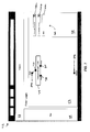
- FIG. 4 illustrates a page 52 of the user interface provided by the logic application 20 .
- the page 52 includes a header section 53 , a navigation section 54 , a display section 56 , and an options section 58 .
- the header section 53 can provide general information about the application 20 , such as logos, titles, instructions, etc.
- the header section 53 can also include selections mechanisms, such as buttons or drop-down menus, for performing basic functions with the application 20 such as starting a new flowchart, saving a current flowchart, opening an existing flowchart, closing an opened flowchart, executing a flowchart to perform a database query, or closing or exiting the logic application 20 .
- the navigation section 54 can include links that allow the user to access various parts or functionality of the application 20 .
- the navigation section 54 can include links to previously created flowcharts or to information about the data 22 (e.g., field names, table names, data types, etc.).
- the display section 56 displays the current flowchart being built by the user.
- the display section 56 can include one or more default steps or nodes 59 , such as a start node 59 a and an end or select node 59 b . These nodes can be automatically displayed in the display section 56 each time the user starts a new flowchart, and the user may be restricted from deleting them or changing their positions.
- the display section 56 does not include a default start node 59 a or a default end node 59 b .
- FIG. 5 illustrates an alternative version of the page 52 where the display section 56 does not include default nodes 59 . Rather, as shown in FIG. 5 , the flowchart displayed in the display section 56 starts with a first step of the flowchart.
- the logic application 20 can be configured to treat any step of a flowchart that does not have an input as a start of the flowchart.
- the display section 56 does not include a default end node 59 b . Rather, the flowchart displayed in FIG. 5 includes a user-placed end step 60 . As described in more detail below, the user places an end step 60 in the flowchart to indicate that they have completed a path of the flowchart. In some embodiments, a flowchart can include multiple end steps 60 . Furthermore, in some embodiments, the flowchart created by the user may not include any end steps 60 . In these embodiments, the logic application 20 can be configured to treat any step of a flowchart that does not have any outputs as an end of a path for the flowchart.
- the option section 58 displays various options to the user depending on the user's current state in creating a flowchart. For example, in FIG. 4 , the user is ready to add a new flowchart or filter step, so the page 52 displays step type options 61 in the options section 58 .
- the user can select one of the step type options 61 to create a flowchart step with a pre-defined logical expression format.
- the step type options 61 can include a value-comparison type, a field-comparison type, a sub-filter type, an aggregator-value-comparison type, an aggregator-field-comparison type, and a related record type.
- the value comparison type includes a logical expression format that compares a particular data field included in the data 22 to a user-entered value.
- the field-comparison type compares a data field included in the data 22 to another data field included in the data 22 .
- the sub-filter type inserts the logic from another flowchart created with the logic application 20 .
- the aggregator-value-comparison type compares an aggregation (e.g., min, max, sum, or average) of a data field included in the data 22 to a user-entered value.
- the aggregator-field-comparison type compares an aggregation (e.g., min, max, sum, or average) of a data field included in the data 22 to another data field included in the data 22 .
- the related-record type checks for the existence of related data stored in the data 22 . For example, if the data 22 stores records tracking service performed by technicians, the user can use the related-record type to build a logical expression that finds a record that includes a date of a service for a particular technician that is greater than another technician's last date of service.
- the different step types presented by the logic application 20 make it easier for the user to define a logical expression. For example, as described below in more detail, the inputs and selection mechanisms presented to a user for defining a logical expression are tailored to the step type selected by the user. Therefore, the user is guided through the creation of the logical expression based on the type of logical expression the user is attempting to create.
- the logic application 20 can be configured to provide an end step type.
- the user can place an end step 60 to mark the end of a path for a flowchart.
- the options section 58 can list one or more types of end steps 60 as a step type option 61 (see FIG. 5 ).
- the user interface may prompt the user for a description for the end step 60 .
- the end step 60 is associated with a description or reason “Pass,” which indicates to the user that the end step 60 is the end of the path through the flowchart that is defined by the “pass” connections.
- the logic application 20 receives a step type selection from the user (at 62 ).
- the user can select a step type by clicking on a graphic associated with the desired step type option 61 or by dragging the graphic into the display section 56 .
- the logic application 20 can replace the options section 58 with further options for creating a step based on the format of the logical expression associated with the selected step type (at 63 ).
- FIG. 6 illustrates a page 64 of the user interface provided by the logic application 20 .
- the options section 58 illustrated in page 64 includes expression options 66 for the selected step type.
- the expression options 66 illustrated in page 64 are displayed when the user selects the value-comparison step type.
- the expression options 66 include a data-field selection mechanism 66 a , a comparison selection mechanism 66 b , and a user-entered-value selection mechanism 66 c.
- the user uses the data-field selection mechanism 66 a to select a particular data field stored in the data 22 .
- the data field selection mechanism 66 a includes an input box that allows the user to manually type in a data field name.
- the logic application 20 is preprogrammed with the data fields available in the data 22 .
- the logic application 20 is configured to receive parameters of the data 22 during a configuration process to configure the logic application 20 to interact with the data 22 .
- the parameters can include the names of the tables and data fields included in the data 22 .
- the parameters can also include the data type associated with each data field and the relationships between the tables and/or data fields.
- the logic application 20 can use the parameters to generate a drop-down menu for the data-field selection mechanism 66 a that lists available data fields stored in the data 22 . Therefore, using the parameters, the logic application 20 can be used with different sets of data without requiring that the application 20 be pre-programmed to interact with particular data. Similarly, if the data 22 is updated or modified, the logic application 20 can be provided with new parameters, which allows the logic application 20 to be used with the updated data without requiring re-programming of the application 20 .
- the logic application 20 is configured (e.g., through the parameters) to associate a natural language description with each data field and the logic application 20 lists these descriptions in the data-field selection mechanism 66 a . Accordingly, the user can select the data field without knowing the exact name of the data field stored in the data 22 .
- the user selects a data field using the data-field selection mechanism 66 a .
- the user selects a comparison expression (e.g., greater than, less than, greater than or equal to, less than or equal, equal to, not equal to, etc.) using the comparison selection mechanism 66 b (e.g., through a drop-down menu).
- the logic application 20 is configured to tailor the options available through the comparison selection mechanism 66 b based on the data field selected by the user.
- the logical application 20 can list only these options through the comparison selection mechanism 66 b.
- the user After the user selects the data field and the comparison expression, the user enters a value (e.g., a number, text, etc.) using the user-entered-value selection mechanism 66 c .
- a value e.g., a number, text, etc.
- the user-entered-value selection mechanism 66 c includes an input box that allows the user to type in a value.
- the user-entered-value selection mechanism 66 c can provide the user with a list of available values, and the logic application 20 can tailor the available values based on the selected data field and/or the selected comparison expression.
- the logic application 20 compares the user-entered value with the selected data field as defined by the selected comparison expression. For example, as shown in FIG.
- the user entered “500” in the user-entered-value selection mechanism 66 c selected the data field “Charged Amount,” and selected the comparison expression “Is Greater Than.”Therefore, the logical expression defined by the user for the flowchart step will determine if the “Charged Amount” “Is Greater Than” “500.”
- the logic application 20 creates a graphical flowchart step based on the selections (at 68 ).
- the logic application 20 displays the graphical flowchart step in the display section 56 (at 70 ).
- FIG. 7 illustrates a page 72 of the user interface generated by the logic application 20 that displays a graphical step 74 representing the logical expression created by the user through the expression options 66 illustrated in FIG. 6 .
- the step 74 includes a description of the logical expression in a natural language (as opposed to a computer programming language, such as structured query language (“SQL”)).
- SQL structured query language
- the logic application 20 displays the step 74 in the display section 56 as soon as the user selects one of the step type options 61 .
- the logic application 20 then updates the step 74 as the user defines the logical expression for the step 74 using the expression options 66 .
- each step 74 includes one or more inputs 76 .
- Each step 74 can also include one or more “fail” outputs 78 and one or more “pass” outputs 80 .
- the user can connect the inputs 76 and the outputs 78 and 80 of a step 74 to other steps 74 or to the default nodes 59 displayed in the display section 56 .
- the user can connect an input 76 of a step 74 to one or more outputs of other steps 74 or to the start node 59 a .
- the user can connect the outputs 78 and 80 of a step 74 to the inputs of one or more other steps 74 or to the select node 59 b .
- the logic application 20 can be configured to graphically display the connections provided by the user (as connecting lines between the steps 74 ) in the display section 56 .
- an end step 60 can include one or more inputs 76 , but, because the end step 60 marks the end of a flowchart path, the end step 60 may not include any outputs.
- the logic application 20 is configured to place a new step 74 in a default position in the displayed flowchart. For example, as shown in FIG. 7 , if the new step 74 is the first step of the flowchart, the logic application 20 can be configured to automatically place the new step 74 under the start node 59 a and can automatically connect the input 76 of the new step 74 to the start node 59 a . Similarly, if the flowchart includes existing steps 74 , the logic application 20 can be configured to automatically place a new step 74 after the last-created step 74 and can also be configured to automatically connect the input 76 of the new step 74 to at least one of the outputs 78 or 80 of the last-created step 74 .
- the above process can be repeated for each step 74 the user wants to add to the flowchart (at 82 ).
- the logic application 20 can display the step type options 61 the user (see FIG. 4 ).
- the user can select a selection mechanism, such as a “done” button to indicate that the user has completed the current step 74 and is ready to add another step 74 (see FIG. 18 ).
- FIG. 8 illustrates a page 84 of the user interface provided by the logic application 20 when the user indicates that he or she wants to add a field-comparison step type to the current flowchart.
- the page 84 includes expression options 66 that include a first data-field selection mechanism 66 d , a comparison selection mechanism 66 e , a second data-field selection mechanism 66 f , a mathematical expression selection mechanism 66 g , and a user-entered-value selection mechanism 66 h .
- the user uses the data-field selection mechanisms 66 d and 66 f to select two data fields included in the data 22 .
- the user selects one or both of the data fields, the user selects a comparison expression (e.g., greater than, less than, greater than or equal to, less than or equal, equal to, not equal to, etc.) using the comparison selection mechanism 66 e .
- the user can also modify the second data field using the mathematical-expression selection mechanism 66 g and the user-entered-value selection mechanism 66 h .
- the user can specify a mathematical algorithm and a numerical value to apply to the second data field before comparing the second data field to the first data field. For example, as illustrated in FIG.
- the user can divide the data field “Charged Amount” by 2 before comparing the data field to the data field “Paid Amount.” If the user does not want to modify the second data field, the user can leave the mathematical-expression selection mechanism 66 g and the user-entered-value selection mechanism 66 h blank. After the user selects all of the options for the field-comparison step, the logic application 20 displays the step 74 in the display section 56 and the user can move the step 74 to a desired location and provides connections for the step 74 as described above.
- the other step types can be associated with similar expression options 66 .
- the aggregator-value-comparison step type can be associated with an aggregation selection mechanism (allowing the user to select from an aggregating mathematical function, such as minimum, maximum, summation, or average), a data-field selection mechanism, and a user-entered-value selection mechanism.
- the aggregator-value-comparison step type can be associated with an aggregation selection mechanism and two data-field selection mechanisms.
- the related-record step type can be associated with one or more relationship selection mechanisms (e.g., first, last, greatest, smallest, etc.) and one or more data-field selection mechanisms.
- sub-filter step type can be associated with a flowchart selection mechanism that allows the user to select a flowchart previously created with the logic application 20 .
- end step types can be associated with a user-entered-value selection mechanism that allows the user to enter a description or reason for the end step 60 .
- an output 78 or 80 of a step 74 can be connected to a plurality of other steps 74 through a plurality of “pass” connections and/or through a plurality of “fail” connections.
- FIG. 9 illustrates a page 85 that includes a flowchart where steps 74 are connected to multiple other steps 74 .
- the top step 74 is connected to three steps 74 by “pass” connections through the step's “pass” output 80 .
- the ability to connect a step 74 to multiple other steps 74 along multiple “fail” connections and/or multiple “pass” connections allows the user to create complex and compact logic. In particular, without the ability to connect a step 74 to other steps 74 through multiple “fail” connections and/or multiple “pass” connections, the user would be required to create very long and complex flowcharts to express particular logic.
- the user can use the same page or a similar page he or she used to create a step 74 to edit the step 74 .
- the logic application 20 can display the expression options 66 associated with the selected step 74 .
- the user can then modify the expression options selections for the step 74 as necessary.
- the logic application 20 highlights the step 74 selected by the user (e.g., by placing a thicker border around the step 74 ), so that the user know what step 74 will be modified if the user changes the logical expression through the displayed expression options 66 .
- the user can select a “run” or “execute” button displayed on a page of the user interface generated by the logic application 20 .
- the logic application 20 can convert the graphical flowchart to a database query for the data 22 (e.g., a SQL statement) (at 86 ).
- the logic application 20 can trace the paths of the graphical flowchart displayed in the display section 56 and can translate the paths into a series of database query statements based on the logical expression associated with each step 74 and the connections between each step 74 .
- the logic application 20 can translate the logical expression associated with each step 74 to a proper database query statement. This can include generating a statement that includes the full data field name, as opposed to the natural language description, for each field name referenced in a step 74 .
- a step 74 may reference a database field named “Bill Type,” the proper database field name may be “bill_type.”
- the logic application 20 also creates the database query statements for a flowchart step 74 based on the step's connections.
- FIG. 10 illustrates a sample flowchart path created by a user through the logic application 20 .
- the sample flowchart path includes a step 74 and an end step 60 connected by a “pass” connection (i.e., the “pass” output 80 of the step 74 is connected to the input 76 of the end step 60 ).
- FIG. 10 illustrates a sample flowchart path created by a user through the logic application 20 .
- the sample flowchart path includes a step 74 and an end step 60 connected by a “pass” connection (i.e., the “pass” output 80 of the step 74 is connected to the input 76 of the end step 60 ).
- FIG. 11 illustrates a sample flowchart path including a step 74 connected to an end step 60 by a “fail” connection (i.e., the “fail” output 78 of the step 74 is connected to the input 76 of the end step 60 ).
- FIGS. 12-15 illustrate sample flowchart paths that include multiple steps 74 .
- FIG. 16 illustrates a sample flowchart including two flowchart paths.
- the first flowchart path is defined by the step 74 labeled “Bill Type Equals 488” and the end step 60 .
- the second flowchart path is defined by the step 74 labeled “Charged Amount Greater Than 500” and the end step 60 .
- FIG. 17 illustrates a sample flowchart including two flowchart paths.
- the first flowchart path starts with the step 74 labeled “Bill Type Equals 488” and the second flowchart path starts with the step 74 labeled “Charged Amount Greater Than 5000.”
- this SQL statement may not yield the results desired by the user based on the structure of flowchart.
- parentheses illustrated in the above sample SQL statements are used to mark an order of operations or logical groupings.
- the logic application 20 may be configured to include additional parentheses in generated database query statements for ease of implementation.
- the logic application 20 can optionally display the query to the user so that the user can edit the query, copy the query to other data mining applications, combine the query with additional statements, or simply educate themselves on the format of the query.
- the logic application 20 can also be configured to execute the database query to retrieve the data 22 or a portion thereof (at 88 ).
- the logic application 20 can output the retrieved results in various forms, such as by displaying the results on a display, outputting the results to a printer, emailing the results to the user, exporting the results to a file, or importing the results to another software application, such as a report generation application.
- the user can also save a created flowchart to computer-readable media and can reload the flowchart in the logic application 20 if the user wants to edit the logic represented by the flowchart or re-run the logic to retrieve new data. Also, as described above, a user can load a saved flowchart as a step 74 of a larger flowchart, which allows the user to build large, complex flowcharts using predefined sub-flowcharts.
- the layouts and configurations of the pages of the user interface included in the present application are provided as examples.
- the layouts of the pages can be varied and the functionality provided through each page can be distributed across multiple pages or combined with other pages.
- the options section 58 is displayed on top of the display section 56 .
- some of the sections of the pages can be optional, such as the navigation section 54 .
- the functionality performed by the logic application 20 can be distributed among multiple applications.
- the logic application 20 may be configured to generate a database query based on the graphical flowchart and then may transfer the database query to a separate application that executes the query and outputs the results.
- the logic application 20 may be configured to generate a database query and save the database query to computer-readable media. After the database query is saved, the user can open the database query with a separate application to view, edit, and/or execute the query.
Abstract
Description
(paid_amount>10000 AND bill_type=‘488’)
OR
(NOT (charged_amount>paid_amount*3) AND NOT (cpt_code LIKE ‘555%’) AND bill_type=‘488’)
OR
((charged_amount>paid_amount*3 AND NOT (cpt_code LIKE ‘555%’) AND bill_type=‘488’) OR (cpt_code IN (‘55512,’ ‘55514’) AND bill_type=‘488’))
Claims (23)
Priority Applications (1)
| Application Number | Priority Date | Filing Date | Title |
|---|---|---|---|
| US13/286,850 US8887076B2 (en) | 2011-11-01 | 2011-11-01 | Software user interface allowing logical expression to be expressed as a flowchart |
Applications Claiming Priority (1)
| Application Number | Priority Date | Filing Date | Title |
|---|---|---|---|
| US13/286,850 US8887076B2 (en) | 2011-11-01 | 2011-11-01 | Software user interface allowing logical expression to be expressed as a flowchart |
Publications (2)
| Publication Number | Publication Date |
|---|---|
| US20130111375A1 US20130111375A1 (en) | 2013-05-02 |
| US8887076B2 true US8887076B2 (en) | 2014-11-11 |
Family
ID=48173776
Family Applications (1)
| Application Number | Title | Priority Date | Filing Date |
|---|---|---|---|
| US13/286,850 Active 2032-03-24 US8887076B2 (en) | 2011-11-01 | 2011-11-01 | Software user interface allowing logical expression to be expressed as a flowchart |
Country Status (1)
| Country | Link |
|---|---|
| US (1) | US8887076B2 (en) |
Cited By (2)
| Publication number | Priority date | Publication date | Assignee | Title |
|---|---|---|---|---|
| US10867273B2 (en) * | 2014-09-26 | 2020-12-15 | Oracle International Corporation | Interface for expanding logical combinations based on relative placement |
| US11188526B2 (en) | 2016-04-12 | 2021-11-30 | Koninklijke Philips N.V. | Database query creation |
Families Citing this family (11)
| Publication number | Priority date | Publication date | Assignee | Title |
|---|---|---|---|---|
| US9507838B2 (en) * | 2013-05-17 | 2016-11-29 | Oracle International Corporation | Use of projector and selector component types for ETL map design |
| US10216814B2 (en) * | 2013-05-17 | 2019-02-26 | Oracle International Corporation | Supporting combination of flow based ETL and entity relationship based ETL |
| US9542376B2 (en) * | 2013-12-11 | 2017-01-10 | Sehul S. SHAH | System and method for creating, editing, and navigating one or more flowcharts |
| GB2528697A (en) * | 2014-07-29 | 2016-02-03 | Ibm | Generating a database structure from a scanned drawing |
| US20160171050A1 (en) * | 2014-11-20 | 2016-06-16 | Subrata Das | Distributed Analytical Search Utilizing Semantic Analysis of Natural Language |
| US10262271B1 (en) * | 2018-02-14 | 2019-04-16 | DataTron Technologies Inc. | Systems and methods for modeling machine learning and data analytics |
| CN110858117B (en) * | 2018-08-24 | 2023-05-02 | 阿里巴巴集团控股有限公司 | Service information configuration method and device and electronic equipment |
| USD1018575S1 (en) * | 2019-12-09 | 2024-03-19 | Caterpillar Inc. | Display screen having a graphical user interface |
| CN111597206A (en) * | 2020-05-27 | 2020-08-28 | 林思明 | Chip type selection method and device, electronic equipment and computer readable storage medium |
| US11809698B1 (en) * | 2022-01-28 | 2023-11-07 | Tableau Software, LLC | Phrase builder for data analytic natural language interface |
| CN116433799B (en) * | 2023-06-14 | 2023-08-25 | 安徽思高智能科技有限公司 | Flow chart generation method and device based on semantic similarity and sub-graph matching |
Citations (39)
| Publication number | Priority date | Publication date | Assignee | Title |
|---|---|---|---|---|
| US5175814A (en) * | 1990-01-30 | 1992-12-29 | Digital Equipment Corporation | Direct manipulation interface for boolean information retrieval |
| US5421008A (en) * | 1991-11-08 | 1995-05-30 | International Business Machines Corporation | System for interactive graphical construction of a data base query and storing of the query object links as an object |
| US5428776A (en) * | 1991-03-12 | 1995-06-27 | Wang Laboratories, Inc. | System for composing a graphical interface to a relational database which displays a network of query and source icons |
| US5428737A (en) * | 1991-10-16 | 1995-06-27 | International Business Machines Corporation | Comprehensive bilateral translation between SQL and graphically depicted queries |
| US5555367A (en) * | 1994-09-30 | 1996-09-10 | General Electric Company | Method and system for generating computer programs for queries formed by manipulating object-oriented diagrams |
| US5574908A (en) * | 1993-08-25 | 1996-11-12 | Asymetrix Corporation | Method and apparatus for generating a query to an information system specified using natural language-like constructs |
| US5619688A (en) * | 1993-09-02 | 1997-04-08 | Microsoft Corporation | Method and system for constructing database queries using a field selection grid |
| US5696916A (en) * | 1985-03-27 | 1997-12-09 | Hitachi, Ltd. | Information storage and retrieval system and display method therefor |
| US5701456A (en) * | 1993-03-17 | 1997-12-23 | International Business Machines Corporation | System and method for interactively formulating database queries using graphical representations |
| US5721901A (en) * | 1992-07-20 | 1998-02-24 | International Business Machines Corporation | Method and apparatus for displaying a dialog box enabling user selections from a database |
| US5842203A (en) * | 1995-12-01 | 1998-11-24 | International Business Machines Corporation | Method and system for performing non-boolean search queries in a graphical user interface |
| US5909678A (en) * | 1996-09-13 | 1999-06-01 | International Business Machines Corporation | Computer systems, method and program for constructing statements by dragging and dropping iconic representations of subcomponent statements onto a phrase template |
| US6111574A (en) * | 1997-04-17 | 2000-08-29 | Microsoft Corporation | Method and system for visually indicating a selection query |
| US6208985B1 (en) * | 1997-07-09 | 2001-03-27 | Caseventure Llc | Data refinery: a direct manipulation user interface for data querying with integrated qualitative and quantitative graphical representations of query construction and query result presentation |
| US6240411B1 (en) * | 1998-06-15 | 2001-05-29 | Exchange Applications, Inc. | Integrating campaign management and data mining |
| US6326962B1 (en) * | 1996-12-23 | 2001-12-04 | Doubleagent Llc | Graphic user interface for database system |
| US6353452B1 (en) * | 1997-10-20 | 2002-03-05 | International Business Machines Corporation | Data item display method and device, and recording medium storing a program for controlling display of data item |
| US6470335B1 (en) | 2000-06-01 | 2002-10-22 | Sas Institute Inc. | System and method for optimizing the structure and display of complex data filters |
| US20020169768A1 (en) * | 2001-05-10 | 2002-11-14 | International Business Machines Corporation | Drag and drop technique for building queries |
| US20030163455A1 (en) * | 2002-02-26 | 2003-08-28 | International Business Machines Corporation | Graphical user interface for building queries with hierarchical conditions |
| US6640221B1 (en) * | 2000-07-10 | 2003-10-28 | Sas Institute Inc. | System and method for configuring, sequencing and viewing joins in a query |
| US6658404B1 (en) * | 1999-09-20 | 2003-12-02 | Libera, Inc. | Single graphical approach for representing and merging boolean logic and mathematical relationship operators |
| US6785668B1 (en) * | 2000-11-28 | 2004-08-31 | Sas Institute Inc. | System and method for data flow analysis of complex data filters |
| US20050004911A1 (en) * | 2002-09-25 | 2005-01-06 | Oracle International Corporation | Graphical condition builder for facilitating database queries |
| US6925608B1 (en) * | 2000-07-05 | 2005-08-02 | Kendyl A. Roman | Graphical user interface for building Boolean queries and viewing search results |
| US20070061742A1 (en) * | 2005-08-26 | 2007-03-15 | Brooks Geoffrey S | Method, system, and program product for graphical authoring |
| US20070156740A1 (en) * | 2005-12-27 | 2007-07-05 | International Business Machines Corporation | Generating a separable query design object and database schema through visual view editing |
| US20070233655A1 (en) * | 2006-04-03 | 2007-10-04 | National Instruments Corporation | Graphical program representation of queries |
| US7366723B2 (en) * | 2004-10-05 | 2008-04-29 | Sap Ag | Visual query modeling for configurable patterns |
| US7370040B1 (en) * | 2000-11-21 | 2008-05-06 | Microsoft Corporation | Searching with adaptively configurable user interface and extensible query language |
| US20080184140A1 (en) * | 2007-01-30 | 2008-07-31 | Sag Ag | Analytics planning in a visual programming environment |
| US20090019022A1 (en) | 2007-07-15 | 2009-01-15 | Dawning Technologies, Inc. | Rules-based data mining |
| US20090024940A1 (en) | 2007-07-18 | 2009-01-22 | Sas Institute Inc. | Systems And Methods For Generating A Database Query Using A Graphical User Interface |
| US20090094217A1 (en) * | 2004-06-10 | 2009-04-09 | International Business Machines Corporation | Dynamic graphical database query interface |
| US7610308B1 (en) | 2004-03-17 | 2009-10-27 | Kam-Ming Chiu | Framework for creating database applications |
| US20090287685A1 (en) * | 2002-02-04 | 2009-11-19 | Cataphora, Inc. | Method and apparatus for sociological data analysis |
| US20100161646A1 (en) * | 2008-12-18 | 2010-06-24 | Oracle International Corporation | Criteria builder for query builder |
| US20100162210A1 (en) * | 2008-12-22 | 2010-06-24 | International Business Machines Corporation | Visual Editor for Editing Complex Expressions |
| US8312382B2 (en) * | 2004-05-11 | 2012-11-13 | Sap Ag | Developing and executing applications with configurable patterns |
-
2011
- 2011-11-01 US US13/286,850 patent/US8887076B2/en active Active
Patent Citations (44)
| Publication number | Priority date | Publication date | Assignee | Title |
|---|---|---|---|---|
| US5696916A (en) * | 1985-03-27 | 1997-12-09 | Hitachi, Ltd. | Information storage and retrieval system and display method therefor |
| US5175814A (en) * | 1990-01-30 | 1992-12-29 | Digital Equipment Corporation | Direct manipulation interface for boolean information retrieval |
| US5428776A (en) * | 1991-03-12 | 1995-06-27 | Wang Laboratories, Inc. | System for composing a graphical interface to a relational database which displays a network of query and source icons |
| US5428737A (en) * | 1991-10-16 | 1995-06-27 | International Business Machines Corporation | Comprehensive bilateral translation between SQL and graphically depicted queries |
| US5421008A (en) * | 1991-11-08 | 1995-05-30 | International Business Machines Corporation | System for interactive graphical construction of a data base query and storing of the query object links as an object |
| US5721901A (en) * | 1992-07-20 | 1998-02-24 | International Business Machines Corporation | Method and apparatus for displaying a dialog box enabling user selections from a database |
| US5701456A (en) * | 1993-03-17 | 1997-12-23 | International Business Machines Corporation | System and method for interactively formulating database queries using graphical representations |
| US5574908A (en) * | 1993-08-25 | 1996-11-12 | Asymetrix Corporation | Method and apparatus for generating a query to an information system specified using natural language-like constructs |
| US5619688A (en) * | 1993-09-02 | 1997-04-08 | Microsoft Corporation | Method and system for constructing database queries using a field selection grid |
| US5555367A (en) * | 1994-09-30 | 1996-09-10 | General Electric Company | Method and system for generating computer programs for queries formed by manipulating object-oriented diagrams |
| US5842203A (en) * | 1995-12-01 | 1998-11-24 | International Business Machines Corporation | Method and system for performing non-boolean search queries in a graphical user interface |
| US5909678A (en) * | 1996-09-13 | 1999-06-01 | International Business Machines Corporation | Computer systems, method and program for constructing statements by dragging and dropping iconic representations of subcomponent statements onto a phrase template |
| US6326962B1 (en) * | 1996-12-23 | 2001-12-04 | Doubleagent Llc | Graphic user interface for database system |
| US6111574A (en) * | 1997-04-17 | 2000-08-29 | Microsoft Corporation | Method and system for visually indicating a selection query |
| US6208985B1 (en) * | 1997-07-09 | 2001-03-27 | Caseventure Llc | Data refinery: a direct manipulation user interface for data querying with integrated qualitative and quantitative graphical representations of query construction and query result presentation |
| US6353452B1 (en) * | 1997-10-20 | 2002-03-05 | International Business Machines Corporation | Data item display method and device, and recording medium storing a program for controlling display of data item |
| US6240411B1 (en) * | 1998-06-15 | 2001-05-29 | Exchange Applications, Inc. | Integrating campaign management and data mining |
| US6658404B1 (en) * | 1999-09-20 | 2003-12-02 | Libera, Inc. | Single graphical approach for representing and merging boolean logic and mathematical relationship operators |
| US6470335B1 (en) | 2000-06-01 | 2002-10-22 | Sas Institute Inc. | System and method for optimizing the structure and display of complex data filters |
| US20050192953A1 (en) * | 2000-07-05 | 2005-09-01 | Kendyl A. Romah And Data Ace Inc | Graphical user interface for building boolean queries and viewing search results |
| US6925608B1 (en) * | 2000-07-05 | 2005-08-02 | Kendyl A. Roman | Graphical user interface for building Boolean queries and viewing search results |
| US6640221B1 (en) * | 2000-07-10 | 2003-10-28 | Sas Institute Inc. | System and method for configuring, sequencing and viewing joins in a query |
| US7370040B1 (en) * | 2000-11-21 | 2008-05-06 | Microsoft Corporation | Searching with adaptively configurable user interface and extensible query language |
| US6785668B1 (en) * | 2000-11-28 | 2004-08-31 | Sas Institute Inc. | System and method for data flow analysis of complex data filters |
| US7668858B2 (en) * | 2001-05-10 | 2010-02-23 | International Business Machines Corporation | Drag and drop technique for building queries |
| US20020169768A1 (en) * | 2001-05-10 | 2002-11-14 | International Business Machines Corporation | Drag and drop technique for building queries |
| US20090287685A1 (en) * | 2002-02-04 | 2009-11-19 | Cataphora, Inc. | Method and apparatus for sociological data analysis |
| US20030163455A1 (en) * | 2002-02-26 | 2003-08-28 | International Business Machines Corporation | Graphical user interface for building queries with hierarchical conditions |
| US6947928B2 (en) * | 2002-02-26 | 2005-09-20 | International Business Machines Corporation | Graphical user interface for building queries with hierarchical conditions |
| US20050004911A1 (en) * | 2002-09-25 | 2005-01-06 | Oracle International Corporation | Graphical condition builder for facilitating database queries |
| US7383513B2 (en) * | 2002-09-25 | 2008-06-03 | Oracle International Corporation | Graphical condition builder for facilitating database queries |
| US7610308B1 (en) | 2004-03-17 | 2009-10-27 | Kam-Ming Chiu | Framework for creating database applications |
| US8312382B2 (en) * | 2004-05-11 | 2012-11-13 | Sap Ag | Developing and executing applications with configurable patterns |
| US20090094217A1 (en) * | 2004-06-10 | 2009-04-09 | International Business Machines Corporation | Dynamic graphical database query interface |
| US7366723B2 (en) * | 2004-10-05 | 2008-04-29 | Sap Ag | Visual query modeling for configurable patterns |
| US20070061742A1 (en) * | 2005-08-26 | 2007-03-15 | Brooks Geoffrey S | Method, system, and program product for graphical authoring |
| US20070156740A1 (en) * | 2005-12-27 | 2007-07-05 | International Business Machines Corporation | Generating a separable query design object and database schema through visual view editing |
| US20070233655A1 (en) * | 2006-04-03 | 2007-10-04 | National Instruments Corporation | Graphical program representation of queries |
| US20080184140A1 (en) * | 2007-01-30 | 2008-07-31 | Sag Ag | Analytics planning in a visual programming environment |
| US20090019022A1 (en) | 2007-07-15 | 2009-01-15 | Dawning Technologies, Inc. | Rules-based data mining |
| US20090024940A1 (en) | 2007-07-18 | 2009-01-22 | Sas Institute Inc. | Systems And Methods For Generating A Database Query Using A Graphical User Interface |
| US20100161646A1 (en) * | 2008-12-18 | 2010-06-24 | Oracle International Corporation | Criteria builder for query builder |
| US8312038B2 (en) * | 2008-12-18 | 2012-11-13 | Oracle International Corporation | Criteria builder for query builder |
| US20100162210A1 (en) * | 2008-12-22 | 2010-06-24 | International Business Machines Corporation | Visual Editor for Editing Complex Expressions |
Cited By (2)
| Publication number | Priority date | Publication date | Assignee | Title |
|---|---|---|---|---|
| US10867273B2 (en) * | 2014-09-26 | 2020-12-15 | Oracle International Corporation | Interface for expanding logical combinations based on relative placement |
| US11188526B2 (en) | 2016-04-12 | 2021-11-30 | Koninklijke Philips N.V. | Database query creation |
Also Published As
| Publication number | Publication date |
|---|---|
| US20130111375A1 (en) | 2013-05-02 |
Similar Documents
| Publication | Publication Date | Title |
|---|---|---|
| US8887076B2 (en) | Software user interface allowing logical expression to be expressed as a flowchart | |
| US10902045B2 (en) | Natural language interface for building data visualizations, including cascading edits to filter expressions | |
| USRE47594E1 (en) | Visual data importer | |
| US9811233B2 (en) | Building applications for configuring processes | |
| US20200089760A1 (en) | Analyzing Natural Language Expressions in a Data Visualization User Interface | |
| AU2020260374B2 (en) | Building reports | |
| US11093242B2 (en) | Automatically mapping data while designing process flows | |
| US7228524B2 (en) | Method and system for analysis of software requirements | |
| US20180032649A1 (en) | Managing Custom REVIT Inheritance-Based Assembly Families for Manufacturing | |
| AU2018236875A1 (en) | Graphical user interface that simplifies user creation of custom calculations for data visualizations | |
| US20220035847A1 (en) | Information retrieval | |
| US10585981B2 (en) | Method of data capture, storage and retrieval through user created form templates and data item templates by executing computer-executable instructions stored on a non-transitory computer-readable medium | |
| US9940182B1 (en) | Business rule engine validation systems and related methods | |
| AU2007200384B2 (en) | Definitions in master documents | |
| CN114297443B (en) | Processing method, device, equipment and storage medium of graph data query statement | |
| WO2020060720A1 (en) | Analyzing natural language expressions in a data visualization user interface | |
| US20240004516A1 (en) | Method and system for creating a data model | |
| US20220245108A1 (en) | Graphical user interface to depict data lineage information in levels | |
| US20220342727A1 (en) | System and method for designing and developing application programming interface | |
| Barnes et al. | Toward database inference by GUI analysis: a case study | |
| Achilleos et al. | Model-driven engineering of non driven engineering of non driven engineering of non-functional properties for Pervasive service creation service creation | |
| Fouché et al. | Reporting Tools | |
| Zehoo | Application Data Entry |
Legal Events
| Date | Code | Title | Description |
|---|---|---|---|
| AS | Assignment |
Owner name: AVER INFORMATICS, INC., WISCONSIN Free format text: ASSIGNMENT OF ASSIGNORS INTEREST;ASSIGNOR:FROHLIGER, MATTHEW SCOTT;REEL/FRAME:027182/0694 Effective date: 20111107 |
|
| STCF | Information on status: patent grant |
Free format text: PATENTED CASE |
|
| MAFP | Maintenance fee payment |
Free format text: PAYMENT OF MAINTENANCE FEE, 4TH YR, SMALL ENTITY (ORIGINAL EVENT CODE: M2551) Year of fee payment: 4 |
|
| MAFP | Maintenance fee payment |
Free format text: PAYMENT OF MAINTENANCE FEE, 8TH YR, SMALL ENTITY (ORIGINAL EVENT CODE: M2552); ENTITY STATUS OF PATENT OWNER: SMALL ENTITY Year of fee payment: 8 |