US8882563B2 - Chemical mechanical polishing system - Google Patents
Chemical mechanical polishing system Download PDFInfo
- Publication number
- US8882563B2 US8882563B2 US13/095,404 US201113095404A US8882563B2 US 8882563 B2 US8882563 B2 US 8882563B2 US 201113095404 A US201113095404 A US 201113095404A US 8882563 B2 US8882563 B2 US 8882563B2
- Authority
- US
- United States
- Prior art keywords
- carrier unit
- substrate carrier
- substrate
- path
- polishing
- Prior art date
- Legal status (The legal status is an assumption and is not a legal conclusion. Google has not performed a legal analysis and makes no representation as to the accuracy of the status listed.)
- Active, expires
Links
Images


Classifications
-
- B—PERFORMING OPERATIONS; TRANSPORTING
- B24—GRINDING; POLISHING
- B24B—MACHINES, DEVICES, OR PROCESSES FOR GRINDING OR POLISHING; DRESSING OR CONDITIONING OF ABRADING SURFACES; FEEDING OF GRINDING, POLISHING, OR LAPPING AGENTS
- B24B37/00—Lapping machines or devices; Accessories
- B24B37/34—Accessories
- B24B37/345—Feeding, loading or unloading work specially adapted to lapping
-
- B—PERFORMING OPERATIONS; TRANSPORTING
- B24—GRINDING; POLISHING
- B24B—MACHINES, DEVICES, OR PROCESSES FOR GRINDING OR POLISHING; DRESSING OR CONDITIONING OF ABRADING SURFACES; FEEDING OF GRINDING, POLISHING, OR LAPPING AGENTS
- B24B37/00—Lapping machines or devices; Accessories
- B24B37/27—Work carriers
- B24B37/30—Work carriers for single side lapping of plane surfaces
Definitions
- the invention relates to a chemical-mechanical polishing system and its method, and more particularly to a chemical-mechanical polishing system in which even though a substrate carrier unit with loading a substrate moves through a circulatory path passing through a plurality of polishing platens, air pressure supply tubes for supplying compressed air to a rotary union are prevented from being twisted, thereby enabling to continuously polish the substrates loaded at the substrate carrier unit on the plurality of polishing platens.
- CMP chemical-mechanical polishing process
- FIGS. 1 to 3 are schematic views of a conventional chemical-mechanical polishing system.
- the chemical-mechanical polishing system comprises a polishing platen 10 driven to rotate with a platen pad 16 and a backing pad 15 which are attached to a platen base 14 on its upper surface, a substrate carrier unit 20 at which a substrate 55 is loaded for being pressed in the downward direction 22 d ′ and rotating in the direction 22 d , and a slurry supply part 30 for providing a slurry 30 a on the upper surface of the platen pad 16 .
- a rotational driving force by a motor 12 is delivered to a shaft 13 through a power transmission belt 11 , so that the platen base 14 rotates together with the shaft 13 .
- a backing layer 15 made of a soft material and a platen pad 16 for the polishing process are applied on the upper surface of the platen base 14 , respectively.
- the substrate carrier unit 20 includes a carrier head 21 for loading and holding the substrate 55 , a rotating shaft 22 driven to rotate integrally with the carrier head 21 , a motor 23 for driving the rotating shaft 22 , a pinion 24 secured to a motor shaft and a gear 25 fixed to the rotating shaft 22 for transmitting the driving force of the motor 23 to the rotating shaft 22 , a driving support 26 for rotatably receiving the rotating shaft 22 , and a cylinder 27 for moving the driving support 26 upwards and downwardly and pressing down the substrate 55 against the platen pad 16 .
- the substrate 55 rotates and makes contact with the platen pad 16 , while being pressed downwardly at an separated position from the rotating center of the platen pad 16 , and also the platen pad 16 rotates simultaneously.
- slurry 30 a containing abrasives and chemical materials is supplied through the slurry supply tube 30 on the platen pad 16 , the slurry is introduced to contact surfaces between the substrate 55 and the platen pad 16 through groove patterns with a predetermined width and depth in a X-Y direction on the upper surface of the platen pad 16 , thereby polishing the surface of the substrate 55 .
- constructions to press down the substrate 55 against the platen pad 15 can be embodied by a rotary union which drives fluids therein upon receiving an electrical signal, whose constructions are well disclosed in the Korean Laid-Open Patent No. 2004-75114.
- the substrates 55 can be polished one by one by contacting the platen pad 16 after one substrate is loaded and held by the carrier head 21 of the substrate carrier unit 20 .
- it can be constructed in a manner that a plurality of substrates 55 can be polished simultaneously as illustrated in the Korean Laid-Open Patent No. 2005-12586.
- a chemical-mechanical polishing system 1 has been used in which a carrier transporter 40 divided into a plurality of branches and installed rotatably about a rotating center 41 is provided, a carrier unit 20 is installed at the ends 40 A, 40 S and 40 C of the carrier transporter 40 , and when new substrates 55 s and 55 ′ are mounted on the carrier unit 20 by means of a substrate loading/unloading unit K, the carrier transporter 40 rotates to simultaneously polish a plurality of substrates 55 mounted at the ends 40 A, 40 S and 40 C of the carrier transporter 40 on the respective polishing platens 10 , 10 ′ and 10 ′′.
- the conventional chemical-mechanical polishing system 1 shown in FIG. 3 is capable of simultaneously polishing a plurality of substrates 55 on the plural polishing platens 10 , 10 ′ and 10 ′, it has to supply electricity or compressed air for driving the motor 23 , the cylinder 27 or the rotary union to each substrate carrier unit 20 disposed at the ends 40 A, 40 S and 40 C of the carrier transporter 40 .
- the air pressure supply tubes are extended along the branches, it has drawbacks in that the air pressure supply tubes might become twisted around each other due to the rotation of the carrier transporter 40 , which needs a certain operation to restore them to their initial positions, thereby lowering the efficiency of the polishing process.
- the invention provides a chemical-mechanical polishing apparatus, comprising: at least one polishing platens rotatably installed with a platen pad mounted on its upper surface; a guide rail disposed along a predetermined path; a substrate carrier unit including a rotary union to downwardly press a substrate during a polishing process, the substrate carrier unit moving along the guide rail with loading the substrate; and a docking unit installed to be docked to the substrate carrier unit so as to supply air pressure to the rotary union which downwardly presses the substrate held by the substrate carrier unit, when the substrate carrier unit is positioned over the polishing platen.
- the substrate carrier unit can be transported between the first and second paths separated from each other by the movement of the carrier holder, which makes it possible to form the travel path of the substrate carrier unit in a circulatory path without providing a curved path occupying a large space. That is, it can be appreciated that the travel path of the substrate carrier unit can be constructed in a circulatory shape, while its occupying space can be minimized.
- the travel path of the substrate carrier unit is not formed in a continuous shape and is constructed in such a manner that the separated paths are to be selectively connected through the movement of the carrier holder, it is possible to freely design the travel path of the substrate carrier unit in various shapes.
- the travel path of the substrate carrier unit can be formed in a rectangular, square, circular shape or any other shape.
- the travel path of the substrate carrier unit when the travel path of the substrate carrier unit is formed in a circulatory travel path, it has advantages in that it has excellent expandability.
- the circulatory travel path is constructed as a single loop-shaped guide rail, the loop-shaped guide rail has to be disassembled so as to insert a new polishing platen into the circulatory travel path in a case that a new polishing platen needs to be added.
- the chemical mechanical polishing system of the invention since the first and second paths are separated and can be connected to each other at a right angle, it can be easily expanded by inserting a frame provided with a polishing platen in the straight travel path.
- the invention provides a method for downwardly pressing a substrate carrier unit using a rotary union during the polishing process of a substrate mounted on the substrate carrier unit which moves along a predetermined path, including the steps of: moving the substrate carrier without an air pressure generating source to a predetermined position over a polishing platen; docking a docking unit disposed in a predetermined position to the substrate carrier unit; supplying compressed air from the docking unit to the substrate carrier unit; and driving the substrate carrier unit supplied with compressed air to press the mounted substrate downwardly.
- the substrate carrier unit of the chemical mechanical polishing system of the invention does not need driving sources for moving the substrate carrier unit or rotating the substrate, or an air pressure generating source for supplying compressed air to the rotary union, but only requires a part of delivering power.
- the substrate carrier unit is capable of traveling along a predetermined path by controlling the electric current of coils arranged outside thereof, and by being docked with the docking unit and then being supplied with an air pressure for driving the substrate to rotate. Therefore, even though the substrate carrier unit travels repeatedly along the circulatory path, the electrical wirings or air pressure supply tubes are not twisted.
- the substrate carrier unit is differently position-controlled and can move independently without effects of the electrical wirings or the like, it is possible to construct a single circulatory path with respect to plural polishing platens, and accordingly to simultaneously polish a plurality of substrates.
- the invention is constructed in such a manner that the air pressure supply tubes following the movement of the substrate carrier unit does not required and then is removed, and that the docking unit is docked to the substrate carrier unit to deliver the rotational driving force to the substrate carrier unit in a position where the substrate loaded on the substrate carrier unit is polished.
- the invention allows two or more substrates to be consecutively polished, which increases the productivity of the polishing process, and substantially prevents the air pressure supply tubes from being twisted during the simultaneous polishing processes of two or more substrates, thereby ensuring reliable use of the system without failure of the electrical wirings for a long period of time.
- the invention makes it possible to control the movement of a plurality of substrates only in any one direction without twisting of the electrical wirings or the like, which improves the efficiency of the simultaneous polishing processes of the plural substrates.
- FIG. 1 is a schematic view illustrating constructions of a general chemical mechanical polishing system in the prior art
- FIG. 2 is a detailed cross sectional view of constructions of a polishing platen and a carrier unit of FIG. 1 ;
- FIG. 3 is a plan view of FIG. 1 ;
- FIG. 4 is a plan view illustrating arrangements of a chemical mechanical polishing system in accordance with a preferred embodiment of the invention.
- FIG. 5 is a schematic view illustrating a circulatory path in FIG. 4 ;
- FIG. 6 is a perspective bottom view of constructions of the chemical mechanical polishing system excluding the polishing platen;
- FIG. 7 is a side elevation view of FIG. 4 ;
- FIG. 8 is a longitudinal cross sectional view by a cut line A-A of FIG. 7 ;
- FIG. 9 is an enlarged perspective view of ‘X’ in FIG. 6 ;
- FIG. 10 is a cut-away perspective view of a substrate carrier unit of FIG. 9 ;
- FIG. 11 is a side elevation view of FIG. 10 ;
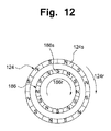
- FIG. 12 is a schematic view illustrating a construction wherein the rotational driving force of a docking unit is delivered to a driven shaft of the substrate carrier unit;
- FIG. 13 is a schematic view illustrating the delivery of an electrical power of a rotational driving force of a docking unit to the substrate carrier unit.
- FIG. 4 is a plan view illustrating arrangements of a chemical mechanical polishing system in accordance with a preferred embodiment of the invention
- FIG. 5 is a schematic view illustrating a circulatory path in FIG. 4
- FIG. 6 is a perspective bottom view of constructions of the chemical mechanical polishing system excluding the polishing platen
- FIG. 7 is a side elevation view of FIG. 4
- FIG. 8 is a longitudinal cross sectional view by a cut line A-A of FIG. 7
- FIG. 9 is an enlarged perspective view of ‘X’ in FIG. 6
- FIG. 10 is a cut away perspective view of a substrate carrier unit of FIG. 9
- FIG. 11 is a side elevation view of FIG. 10
- FIG. 12 is a schematic view illustrating a construction wherein the rotational driving force of a docking unit is delivered to a driven shaft of the substrate carrier unit; and
- a chemical mechanical polishing system 100 in accordance with a preferred embodiment of the invention, includes: a plurality of polishing platens 110 rotatably installed at a frame 10 and having a platen pad mounted on its upper surface; a substrate carrier unit 120 provided with a rotary union 123 therein, moving with a substrate 55 mounted on its lower part to polish the mounted substrate 55 on the polishing platen 110 ; guide rails 132 R, 134 R, 135 R and 136 R for moving or holding the substrate carrier unit 120 along a predetermined path 130 ; a slurry supply unit 150 for supplying slurry on the platen pad when the substrate 55 rotates to be polished on the polishing platen 110 ; a conditioner 140 for uniformly supplying the slurry supplied by the slurry supply unit 150 on the platen pad; a substrate loading unit 160 for providing the substrate 55 to be polished to the substrate carrier unit 120 positioned on the path 130 ; a substrate unloading unit 170 for unloading the polished substrate 55 from the substrate
- the polishing platen 110 is rotatably secured to a frame 10 , 10 ′ and 10 ′′ to polish the substrate 55 such as a wafer or the like.
- a platen pad for polishing the substrate 55 is attached onto its uppermost layer, and a backing layer of softer material interposed beneath the platen pad, whose individual construction becomes similar to or the same as the polishing platen 10 shown in FIG. 3 .
- a plurality of polishing platens 110 are arranged in a first path 132 out of a circulatory path 130 which includes paths arrayed in a non-consecutive and separate manner with a straight pattern.
- the substrate carrier unit 120 is operated to move the substrate 55 only in one (left) direction to be polished on the polishing platen 110 .
- the substrate 55 to be polished is uniformly moved only in one direction to perform the polishing process of the substrate 55 , thereby improving the efficiency of the polishing process.
- the conditioner 140 when the slurry is supplied on the platen pad of the polishing platen 110 from the slurry supply unit 150 , performs a sweeping movement in a direction as indicated by reference numeral 140 d in the drawings to allow the slurry on the platen pad to be uniformly spread. Hence, the slurry being supplied is uniformly applied on the substrate 55 in a sufficient quantity, while the substrate 55 mounted on a carrier head 121 comes in contact with the platen pad and rotates relatively to the latter.
- the slurry supply unit 150 is designed to supply the slurry onto the platen pad of the polishing platen 110 .
- the polishing process needs to be performed with two or more kinds of the slurry to polish the substrate 55 , the polishing process has to be carried out on respective different polishing platens 110 .
- the slurry to be supplied onto the polishing platen 110 is not uniformly applied, and proper slurry is selected and supplied in turn onto the polishing platen 110 depending upon the polishing process.
- the circulatory path 130 includes two rows of a first path 132 passing through the plural polishing platens 110 , a third path 134 disposed parallel to the first path 132 between two rows of the first rows 132 , and a pair of second paths 131 and 133 arranged at opposite ends of the first path 132 and the third path 134 .
- the first path 132 is defined by a first guide rail 132 R, the second paths 131 and 133 by a fixed rail 131 R and 133 R, and the third path 134 by a third guide rail 134 R.
- the respective paths 131 to 134 are arranged in the form of unconnected plural paths with one another.
- Carrier holders 135 and 136 make the substrate carrier unit 120 travel across the unconnected paths because the carrier holders 135 and 136 can accommodate and move together with the substrate carrier unit 120 across the unconnected paths. Therefore, the carrier holders 135 and 136 are provided in the second paths 131 and 133 , so that the substrate carrier unit 120 can be in a state where it can travel through the segmented paths 131 to 134 only when carrier holders 135 and 136 reach positions P 1 , P 2 , P 3 , P 4 and P 5 at which the substrate carrier unit 120 can be transferred to the first path 132 or the third path 134 .
- the substrate carrier unit 120 moves by itself along the first guide rail 132 R and the third guide rail 134 R in the first path 132 and the third path 134 , respectively.
- the substrate carrier unit 120 cannot move solely along fixed rails 131 R and 133 R in the second paths 131 and 133 , and the substrate carrier unit 120 only can move along the fixed rails 131 R and 133 R by the movement of the carrier holders 135 and 136 after being in a state of being accommodated at the carrier holders 135 and 136 .
- the carrier holders 135 and 136 are provided with a pair of second guide rails 135 R and 136 R which face the same direction and have the same dimensions and spacing as the first guide rail 132 R and the third guide rail 134 R to define the first path 132 and the third path 134 .
- the substrate carrier unit 120 can smoothly and easily travel back and forth from the first path 132 and the third path 134 to the second paths 131 and 133 .
- the second paths 131 and 133 which are spaced apart and arranged at right angles at the opposite ends of the first path 132 and the third path 134 are separated from each other.
- the third guide rail 134 R for guiding the third path 134 can be closely arranged without any gaps with the first guide rail 132 R for guiding the first path 132 . In other words, it is possible to manufacture the path of the substrate carrier unit 120 in a compact and close manner.
- the chemical mechanical polishing system of the invention has arrangements of having the carrier holders 135 and 136 , it is possible to array the same in a rectangular shape, thereby embodying a compact facility. Further, as shown in FIG. 4 , it has advantages in that the present system can easily increase or decrease the number of the polishing platens by inserting or withdrawing the frame 10 ′′ having the polishing platen 110 , the first guide rail 132 R and third guide rail 134 R to/from the existing facility. Similarly, the number of the polishing platens can be simply adjusted through selectively adding or removing the first path 132 and the third path 134 with respect to the construction shown in FIG. 5 . As such, the chemical mechanical polishing system of the invention allows the polishing facility to be easily expanded depending upon a production scheme.
- coils 90 arrayed parallel and facing to the travel path of the substrate carrier unit 120 are not formed in a unitary member with a single path, but arrayed in a segmented pattern.
- the substrate carrier unit 120 can consecutively move along the segmented coils 90 of the newly inserted frame and the segmented coils 90 of the existing frame, which makes it easy to expand the number of the polishing platens and has advantages in that each frame can be fabricated by a unit of a module.
- the substrate carrier unit 120 having various components 123 to 127 fixed within its casing 122 is controlled to move along the path 130 , and the plural substrate carrier units 120 are independently controlled to move individually.
- the substrate carrier unit 120 is indicated by ‘densely packed vertical lines’.
- the substrate carrier unit 120 travels along the straight guide rails 132 R, 133 R, 134 R, 135 R and 136 R arranged at opposite sides thereof. Hence, the substrate carrier unit 120 maintains its posture facing a constant direction all the time, so it experiences only a translational movement, not a rotational movement during its transportation.
- each substrate carrier unit 120 includes: a carrier head 121 for holding the substrate 55 , a rotary union 123 for pressing the substrate 55 in its surface direction with allowing its rotation, a driven shaft 124 having a hollow part to receive a rotational driving force from a docking unit 180 , power transmission elements 125 composed of a shaft, a gear or the like for transmitting the rotational driving force delivered to the driven shaft 124 , a follower gear installed on the rotating shaft of the carrier head 121 for driving the carrier head 121 through the rotational driving force delivered by the power transmission elements 125 , a guide roller rotatably installed at the opposite upper and lower parts of the substrate carrier unit 120 for receiving guide rails 132 R, 134 R, 135 R and 136 R in a space formed therebetween, and a permanent magnetic strip 128 alternatively arrayed with a N-pole permanent magnet 128 n and a S-pole permanent magnet 128 s on its upper surface for moving the substrate carrier unit 120 using a linear
- the rotary union 123 is constructed similarly to constructions and operations disclosed in the Korea Patent Laid-Open No. 2004-75114.
- first guide rail 132 R of the first path 132 the third guide rail 134 R of the third path 134 , and the fixed rails 131 R and 133 R of the second paths 131 and 133 are fixedly secured to the frame 10 .
- first guide rail 132 R and the third guide rail 134 R are connected and fixed to a bracket 30 G which is extended downwardly from the frame 10 .
- the coils 90 are arranged and spaced apart from the permanent magnet strip 128 provided on the upper part of the substrate carrier unit 120 along the direction of the paths 132 and 133 .
- the substrate carrier unit 120 moves, guided by the guide rails 132 R and 134 R along the first path 132 and the third path 134 by the operational principle of a linear motor through the co-operation of the coils 90 and the permanent magnetic strip.
- the coils 90 are arrayed and spaced apart from the permanent magnetic strip (not shown) provided on the upper part of the substrate carrier unit 120 . Accordingly, by adjusting the intensity and direction of the electric current applied to the coils 90 , the carrier holders 135 and 136 move, guided by the fixed rails 131 R and 133 R along the second paths 131 and 133 by the operational principle of a linear motor through the co-operation of the coils 90 and the permanent magnetic strip.
- the coils 90 are arranged on the upper part of the carrier holders 135 and 136 , so that the substrate carrier unit 120 can move outside and inside of the carrier holders 135 and 136 by the co-operation with the permanent magnet strip 128 arrayed on the upper part of the substrate carrier unit 120 .
- soundproofing rails G and G′ of a rubber material are attached to the end portions of the guide rails 132 R, 134 R, 135 R and 136 R contacting with the guide rollers 127 , 127 U and 127 L, as shown in FIG. 9 , so as to allow more silent movement thereof.
- the docking unit 180 is secured to the frame 10 .
- the docking unit 180 is docked to the substrate carrier unit 120 to transmit a rotational driving force for rotating the substrate 55 and an air pressure needed for the rotary union 123 .
- the docking unit 180 includes: a docking motor 181 for enabling or releasing a docking state with the substrate carrier unit 120 , a lead screw 182 rotated by the docking motor 181 , a movement block 183 provided with female screws to be engaged with the lead screw 182 , wherein the movement block 183 is installed with its rotation restrained and moves in a direction indicated by reference numeral 185 d through the rotation of the lead screw 182 , a supporting body 184 coupled with the movement block 183 , moving together with the movement block 183 in a unitary manner, a driving motor 185 fixed to the supporting body 184 for generating a rotational driving force, a coupling shaft 186 connected to and rotated by the driving motor 185 , and a plurality of compressed air ports 187 connected to and moved together with the supporting body 184 for supplying compressed air through the air pressure supply tube 187 a to the rotary union 123 of the substrate carrier unit 120 .
- a docking motor 181 for enabling or releasing a dock
- the substrate carrier unit 120 is not provided with a driving source to generate a rotational driving force or an air pressure, so it needs to be supplied with a rotational driving force or an air pressure from the outside to perform a polishing process of the substrate 55 mounted at the substrate carrier unit 120 .
- the polishing platen 110 moves upwards, and then the platen pad of the polishing platen 110 comes in contact with the substrate 55 .
- the movement block 183 whose rotation has been restrained moves toward the substrate carrier unit 120 by rotation of the lead screw 182 .
- the supporting body 183 , the driving motor 185 coupled to the supporting body 183 and the coupling shaft 186 move together toward the substrate carrier unit 120 according to the movement of the movement block 183 , so that the coupling shaft 186 is received within the driven hollow shaft 124 with a certain spacing and the compressed air ports 187 are inserted into the air pressure receiving port 123 x of the substrate carrier unit 120 , which constitutes a docking state.
- the coupling shaft 186 provided with alternatively arrayed N-pole permanent magnets and S-pole permanent magnets at its outer periphery and the driven shaft 124 provided with alternatively arrayed N-pole permanent magnets and S-pole permanent magnets at its inner periphery constitute a magnetic coupling and transfer the rotational driving force generated by the driving motor 185 to the substrate carrier unit 120 .
- the rotational driving force delivered to the substrate carrier unit 120 is transmitted to a pinion 125 a rotated together with the driven hollow shaft 124 , and to a transmitting gear 125 b through a worm gear box 125 w , thereby driving the carrier head 121 mounted with the substrate 55 .
- the rotational driving force of the driving motor 185 is transferred to the substrate carrier unit 120 using the magnetic coupling formed by the shafts 124 and 186 .
- the position control of the substrate carrier unit 120 can be performed easily as the rotational driving force is transferred through a non-contact magnetic coupling by the shafts 124 and 186 .
- FIG. 13 which illustrates another embodiment of the invention
- the air pressure connecting port 287 of the air pressure supply tube 287 a of the docking unit 280 is connected to the air pressure receiving port 123 x of the substrate carrier unit 220 to supply an air pressure necessary for the rotary union 223 of the substrate carrier unit 220 .
- FIG. 13 shows another type of construction of the invention wherein a motor 222 for rotating the substrate 55 is mounted on the substrate carrier unit 220 , and an electrical power source 281 a for driving the motor 222 and control signals are transmitted from the docking unit 280 to the substrate carrier unit 220 through connectors 224 and 282 .
- the compressed air is supplied to a plurality of air pressure receiving ports 123 a of the rotary union 123 through the air pressure supply tubes 187 a , respectively.
- the air pressure supply tube 187 a and the air pressure connecting port 187 have to be connected in the same number as those of the air pressure receiving port 123 x at the same time, delivering the air pressure from the outside to the rotary union 123 .
- the docking motor 181 rotates in a reverse direction to release the docking state between the docking unit 180 and the substrate carrier unit 120 . Then, the substrate carrier unit 120 moves to another polishing platen for performing a next polishing process, otherwise it moves to the substrate unloading unit 170 of the second path 131 through another second path 133 and the third path 134 when all of the polishing process is finished.
- Step 1 First, a substrate carrier unit 120 in a state positioned in a carrier holder 135 is loaded with a substrate 55 from a substrate loading unit 160 . By adjusting an electrical current applied to an upper coil of the carrier holder 135 , the carrier holder 135 is then moved to reach the position P 1 along a fixed rail 131 R defining a second path 131 . At the position P 1 , since a second guide rail 135 R arrayed at the carrier holder 135 is substantially consecutively arranged with a first guide rail 132 R of a first path 132 , the carrier holder 135 can be transferred smoothly from the second path 131 to the first path 132 without any impact.
- Step 2 By adjusting an electrical current flowing in the coils installed at the upper part of the carrier holder 135 , the substrate carrier unit 120 positioned in the carrier holder 135 is transported in a linear motor manner from the second path 131 to a direction indicated by reference numeral 120 d 1 , arriving at the first path 132 . And then, the substrate carrier unit 120 moves to a first polishing platen I to be firstly polished, reaching a position P 2 .
- a docking motor 181 of a docking unit 180 is driven to create a state in which the rotational driving force of the driving motor 185 of the docking unit 180 can be transmitted to the substrate carrier unit 120 .
- the air pressure of the docking unit 180 is delivered to a rotary union 123 to create a state which can press down the substrate 55 towards a platen pad 111 .
- the inner chamber of the rotary union 123 is expanded to move the substrate 55 mounted on a carrier head 121 downwardly, creating a state wherein the substrate 55 comes in contact with the platen pad 111 .
- the rotational driving force is transferred from the docking unit 180 to turn the substrate 55 , so it is possible to perform a chemical mechanical polishing process against the substrate 55 mounted on the substrate carrier unit 120 .
- a chemical mechanical polishing process of the substrate 55 can be performed on the polishing platen I through docking of the docking unit 180 .
- the chemical mechanical polishing system in accordance with the invention has constructions wherein the electrical wirings and air pressure supply tubes following the movement of the conventional substrate carrier unit for rotating the substrate 55 mounted in the substrate carrier unit 120 are removed, and further the docking unit 180 is docked to the substrate carrier unit 120 at a polishing position P 2 , where the substrate 55 is mounted on the substrate carrier unit 120 , to deliver the rotational driving force and air pressure to the substrate carrier unit 120 . Therefore, the invention substantially resolves the phenomenon in which the air pressure supply tubes are twisted by the movement of the substrate carrier unit 120 , which makes it possible to consecutively polish the substrates 55 on the plural polishing platens I, II and III.
- Step 3 After that, polishing processes are performed on one or plural polishing platens from among a first polishing platen I, second polishing platen II, third polishing platen III, and so on depending upon the kinds of the substrate. Meanwhile, although not shown in the drawings, according to another embodiment of the invention, except for the substrate carrier unit 120 under the polishing operation on the polishing platen 110 , there is provided another waiting substrate carrier unit, thereby improving the polishing efficiency at the polishing platen 110 .
- Step 4 Next, when the polishing process of the substrate 55 is completed, the substrate carrier unit 120 moves to a position P 3 through a control of the electrical current of the coils in the first path 132 .
- a carrier holder 136 of a second path 133 moves to a position P 4 and enables a second guide rail 136 R of the carrier holder 136 to be in a consecutive arrangement with the first guide rail 132 R of the first path 132 .
- the substrate carrier unit 120 of the first path 132 can be smoothly transferred in a direction indicated by reference numeral 120 d 2 to the second path 133 .
- the carrier holder 136 receiving the substrate carrier unit 120 moves in a direction indicated by reference numeral 136 d , and a third guide rail 134 R of a third path 134 is consecutively arranged with a second guide rail 136 R of the carrier holder 136 .
- Step 5 Thereafter, both the substrate carrier unit 120 which performs a polishing process in the upper first path 132 and the substrate carrier unit 120 which performs a polishing process in the lower first path 132 release the substrate through the third path 134 .
- the substrate carrier unit 120 in the second path 133 moves in a direction as indicated by reference numeral 120 d 4 and is transferred to the third path 134 , and then it moves to a position P 6 along the third path 134 .
- the carrier holder 135 of the second path 131 moves to a position P 7 and enables the second guide rail 135 R of the carrier holder 135 to be in a consecutive arrangement with the third guide rail 134 R of the third path 134 .
- the substrate carrier unit 120 of the third path 134 can be smoothly transferred in a direction indicated by reference numeral 120 d 5 to the second path 133 .
- Step 6 Then, the substrate carrier unit 120 received in the carrier holder 135 of the second path 131 moves to a substrate unloading unit 170 , and the substrate whose polishing process is completed is released. Thereafter, Steps 1 to 6 are repeated.
- the substrate carrier unit 120 is docked to the docking unit 140 only in the polishing process of the substrate 55 , which needs electrical signals and an air pressure, in order to receive electrical signals, rotational diving forces, and an air pressure necessary for driving the rotary union 123 .
- the substrate carrier unit 120 can freely move along the path 130 without causing the electrical wirings and air pressure supply tubes 183 a to be twisted.
- the substrate carrier unit 120 does not carry a motor therein, it can prevent the electrical wirings from being twisted as well as lower the weight of the substrate carrier unit 120 . Therefore, it can be appreciated that it is easy to control the movement of the substrate carrier unit 120 due to its light-weight and can reduce the power consumption necessary for moving the substrate carrier unit 120 .
Abstract
Description
Claims (9)
Applications Claiming Priority (2)
| Application Number | Priority Date | Filing Date | Title |
|---|---|---|---|
| KR10-2010-0041121 | 2010-04-30 | ||
| KR20100041121A KR101110268B1 (en) | 2010-04-30 | 2010-04-30 | Chemical mechanical polishing system which prevents air pressure tube electric wires from being twisted |
Publications (2)
| Publication Number | Publication Date |
|---|---|
| US20110269378A1 US20110269378A1 (en) | 2011-11-03 |
| US8882563B2 true US8882563B2 (en) | 2014-11-11 |
Family
ID=44858603
Family Applications (1)
| Application Number | Title | Priority Date | Filing Date |
|---|---|---|---|
| US13/095,404 Active 2033-08-16 US8882563B2 (en) | 2010-04-30 | 2011-04-27 | Chemical mechanical polishing system |
Country Status (4)
| Country | Link |
|---|---|
| US (1) | US8882563B2 (en) |
| KR (1) | KR101110268B1 (en) |
| CN (1) | CN102233542B (en) |
| TW (1) | TWI451940B (en) |
Cited By (1)
| Publication number | Priority date | Publication date | Assignee | Title |
|---|---|---|---|---|
| US20160039066A1 (en) * | 2012-03-08 | 2016-02-11 | Applied Materials, Inc. | Pneumatic connection to carrier head and monitoring of the connection |
Families Citing this family (8)
| Publication number | Priority date | Publication date | Assignee | Title |
|---|---|---|---|---|
| MY170824A (en) * | 2012-04-26 | 2019-09-04 | Intevac Inc | System architecture for vacuum processing |
| KR101387979B1 (en) * | 2012-12-24 | 2014-04-22 | 주식회사 케이씨텍 | Carrier unit for chemical mechanical polishing system |
| US9756769B2 (en) * | 2013-07-12 | 2017-09-05 | Fuji Machine Mfg. Co., Ltd. | Feeder automatic distribution control device and feeder automatic distribution control method |
| KR101875386B1 (en) * | 2017-02-07 | 2018-07-06 | 주식회사 케이씨텍 | Chemical mechanical polishing apparatus and control method thereof |
| KR102060400B1 (en) * | 2018-02-13 | 2020-02-11 | 씰링크 주식회사 | Linear movable rotary union |
| CN108417521B (en) * | 2018-05-11 | 2023-08-18 | 罗博特科智能科技股份有限公司 | Quick conveying mechanism of graphite boat |
| CN111421462B (en) * | 2019-01-08 | 2022-03-22 | 中芯国际集成电路制造(上海)有限公司 | Chemical mechanical polishing method |
| CN115338705A (en) * | 2022-06-30 | 2022-11-15 | 杭州众硅电子科技有限公司 | Continuous wafer polishing system |
Citations (12)
| Publication number | Priority date | Publication date | Assignee | Title |
|---|---|---|---|---|
| US20010007810A1 (en) * | 1999-03-03 | 2001-07-12 | Mitsubishi Materials Corporation | Chemical mechanical polishing head assembly having floating wafer carrier and retaining ring |
| US6602724B2 (en) | 2000-07-27 | 2003-08-05 | Applied Materials, Inc. | Chemical mechanical polishing of a metal layer with polishing rate monitoring |
| KR20050012586A (en) | 2003-07-25 | 2005-02-02 | 매그나칩 반도체 유한회사 | chemical mechnical polishing apparatus |
| US6860798B2 (en) * | 2002-08-08 | 2005-03-01 | Micron Technology, Inc. | Carrier assemblies, planarizing apparatuses including carrier assemblies, and methods for planarizing micro-device workpieces |
| US6878038B2 (en) | 2000-07-10 | 2005-04-12 | Applied Materials Inc. | Combined eddy current sensing and optical monitoring for chemical mechanical polishing |
| US6896584B2 (en) * | 1997-07-11 | 2005-05-24 | Applied Materials, Inc. | Method of controlling carrier head with multiple chambers |
| US6924641B1 (en) | 2000-05-19 | 2005-08-02 | Applied Materials, Inc. | Method and apparatus for monitoring a metal layer during chemical mechanical polishing |
| US7001242B2 (en) | 2002-02-06 | 2006-02-21 | Applied Materials, Inc. | Method and apparatus of eddy current monitoring for chemical mechanical polishing |
| US7118457B2 (en) | 2000-05-19 | 2006-10-10 | Applied Materials, Inc. | Method of forming a polishing pad for endpoint detection |
| US7729207B2 (en) | 2007-03-14 | 2010-06-01 | Seiko Epson Corporation | Electronic timepiece with generator function |
| US8172643B2 (en) * | 2008-04-09 | 2012-05-08 | Applied Materials, Inc. | Polishing system having a track |
| US8597084B2 (en) * | 2008-10-16 | 2013-12-03 | Applied Materials, Inc. | Textured platen |
Family Cites Families (8)
| Publication number | Priority date | Publication date | Assignee | Title |
|---|---|---|---|---|
| US5443416A (en) * | 1993-09-09 | 1995-08-22 | Cybeq Systems Incorporated | Rotary union for coupling fluids in a wafer polishing apparatus |
| KR970018240A (en) * | 1995-09-08 | 1997-04-30 | 모리시다 요이치 | Method and apparatus for polishing a semiconductor substrate |
| US6135865A (en) * | 1998-08-31 | 2000-10-24 | International Business Machines Corporation | CMP apparatus with built-in slurry distribution and removal |
| JP4760016B2 (en) * | 2005-01-06 | 2011-08-31 | 日立造船株式会社 | Work transfer device |
| CN101733696A (en) * | 2005-04-19 | 2010-06-16 | 株式会社荏原制作所 | Substrate polishing method and processing method |
| WO2007099976A1 (en) * | 2006-02-22 | 2007-09-07 | Ebara Corporation | Substrate treating device, substrate convey device, substrate grasping device, and chemical solution treating device |
| JP2007229904A (en) * | 2006-03-03 | 2007-09-13 | Disco Abrasive Syst Ltd | Machining device provided with turntable |
| JP5422143B2 (en) * | 2008-06-04 | 2014-02-19 | 株式会社荏原製作所 | Substrate gripping mechanism |
-
2010
- 2010-04-30 KR KR20100041121A patent/KR101110268B1/en active IP Right Grant
-
2011
- 2011-04-27 US US13/095,404 patent/US8882563B2/en active Active
- 2011-04-28 TW TW100114938A patent/TWI451940B/en active
- 2011-05-03 CN CN201110116264.XA patent/CN102233542B/en active Active
Patent Citations (20)
| Publication number | Priority date | Publication date | Assignee | Title |
|---|---|---|---|---|
| US6896584B2 (en) * | 1997-07-11 | 2005-05-24 | Applied Materials, Inc. | Method of controlling carrier head with multiple chambers |
| US20010007810A1 (en) * | 1999-03-03 | 2001-07-12 | Mitsubishi Materials Corporation | Chemical mechanical polishing head assembly having floating wafer carrier and retaining ring |
| US7229340B2 (en) | 2000-05-19 | 2007-06-12 | Applied Materials, Inc. | Monitoring a metal layer during chemical mechanical polishing |
| US7118457B2 (en) | 2000-05-19 | 2006-10-10 | Applied Materials, Inc. | Method of forming a polishing pad for endpoint detection |
| US6924641B1 (en) | 2000-05-19 | 2005-08-02 | Applied Materials, Inc. | Method and apparatus for monitoring a metal layer during chemical mechanical polishing |
| US6930478B2 (en) | 2000-05-19 | 2005-08-16 | Applied Materials, Inc. | Method for monitoring a metal layer during chemical mechanical polishing using a phase difference signal |
| US6975107B2 (en) | 2000-05-19 | 2005-12-13 | Applied Materials, Inc. | Eddy current sensing of metal removal for chemical mechanical polishing |
| US7001246B2 (en) | 2000-05-19 | 2006-02-21 | Applied Materials Inc. | Method and apparatus for monitoring a metal layer during chemical mechanical polishing |
| US7008297B2 (en) | 2000-07-10 | 2006-03-07 | Applied Materials Inc. | Combined eddy current sensing and optical monitoring for chemical mechanical polishing |
| US6878038B2 (en) | 2000-07-10 | 2005-04-12 | Applied Materials Inc. | Combined eddy current sensing and optical monitoring for chemical mechanical polishing |
| US6602724B2 (en) | 2000-07-27 | 2003-08-05 | Applied Materials, Inc. | Chemical mechanical polishing of a metal layer with polishing rate monitoring |
| US6869332B2 (en) | 2000-07-27 | 2005-03-22 | Applied Materials, Inc. | Chemical mechanical polishing of a metal layer with polishing rate monitoring |
| US7001242B2 (en) | 2002-02-06 | 2006-02-21 | Applied Materials, Inc. | Method and apparatus of eddy current monitoring for chemical mechanical polishing |
| US7374477B2 (en) | 2002-02-06 | 2008-05-20 | Applied Materials, Inc. | Polishing pads useful for endpoint detection in chemical mechanical polishing |
| US7591708B2 (en) | 2002-02-06 | 2009-09-22 | Applied Materials, Inc. | Method and apparatus of eddy current monitoring for chemical mechanical polishing |
| US6860798B2 (en) * | 2002-08-08 | 2005-03-01 | Micron Technology, Inc. | Carrier assemblies, planarizing apparatuses including carrier assemblies, and methods for planarizing micro-device workpieces |
| KR20050012586A (en) | 2003-07-25 | 2005-02-02 | 매그나칩 반도체 유한회사 | chemical mechnical polishing apparatus |
| US7729207B2 (en) | 2007-03-14 | 2010-06-01 | Seiko Epson Corporation | Electronic timepiece with generator function |
| US8172643B2 (en) * | 2008-04-09 | 2012-05-08 | Applied Materials, Inc. | Polishing system having a track |
| US8597084B2 (en) * | 2008-10-16 | 2013-12-03 | Applied Materials, Inc. | Textured platen |
Cited By (3)
| Publication number | Priority date | Publication date | Assignee | Title |
|---|---|---|---|---|
| US20160039066A1 (en) * | 2012-03-08 | 2016-02-11 | Applied Materials, Inc. | Pneumatic connection to carrier head and monitoring of the connection |
| US9987718B2 (en) * | 2012-03-08 | 2018-06-05 | Applied Materials, Inc. | Pneumatic connection to carrier head |
| US10974363B2 (en) | 2012-03-08 | 2021-04-13 | Applied Materials, Inc. | Monitoring of pneumatic connection to carrier head |
Also Published As
| Publication number | Publication date |
|---|---|
| CN102233542A (en) | 2011-11-09 |
| CN102233542B (en) | 2014-06-25 |
| TW201143973A (en) | 2011-12-16 |
| KR20110121506A (en) | 2011-11-07 |
| KR101110268B1 (en) | 2012-02-16 |
| US20110269378A1 (en) | 2011-11-03 |
| TWI451940B (en) | 2014-09-11 |
Similar Documents
| Publication | Publication Date | Title |
|---|---|---|
| US8882563B2 (en) | Chemical mechanical polishing system | |
| US8393935B2 (en) | Polishing apparatus | |
| KR101188540B1 (en) | Chemical mechanical polishing apparatus and substrate transfer system thereof | |
| KR20190102945A (en) | Substrate processing apparatus | |
| KR101188579B1 (en) | Chemical mechanical polishing apparatus and substrate transfer system thereof | |
| KR101115743B1 (en) | Chemical mechanical polishing system which prevents electric wires from being twisted | |
| CN207953531U (en) | Wafer processing system | |
| KR20180058933A (en) | Wafer carrier transfer apparartus in chemical mechanical polishing system | |
| KR101163874B1 (en) | Chemical mechanical polishing system which enables to improve transfer efficiency between loading unit and unloading unit | |
| KR101115688B1 (en) | Chemical mechanical polishing system which prevents electric wires from being twisted | |
| KR101187102B1 (en) | Chemical mechanical polishing apparatus and method thereof | |
| KR102317003B1 (en) | Substrate processing apparatus | |
| KR20160055477A (en) | Wafer carrier transfer apparartus in chemical mechanical polishing system | |
| KR101172589B1 (en) | Chemical mechanical polishing system and substrate transfer method used therein | |
| KR101130888B1 (en) | Cleaning device of carrier head in chemical mechanical polishing system and system having same | |
| KR101163949B1 (en) | Chemical mechanical polishing apparatus and method thereof | |
| CN209256650U (en) | Substrate grinding device | |
| KR20190078215A (en) | Polishing head and substrate polishing apparatus having the same | |
| KR102290590B1 (en) | Movable chemical mechanical polishing system | |
| KR20190054697A (en) | Substrate polishing appartus | |
| CN208592708U (en) | Substrate grinding device | |
| KR102137969B1 (en) | Substrate polishing appartus | |
| KR20190092859A (en) | Substrate procesing apparatus and polishing pad using the same | |
| KR102493011B1 (en) | Substrate procesing apparatus | |
| KR102500577B1 (en) | Substrate processing apparatus |
Legal Events
| Date | Code | Title | Description |
|---|---|---|---|
| AS | Assignment |
Owner name: K. C. TECH CO., LTD., KOREA, REPUBLIC OF Free format text: ASSIGNMENT OF ASSIGNORS INTEREST;ASSIGNORS:BOO, JAE PHIL;KIM, DONG SOO;SEO, KEON SIK;AND OTHERS;SIGNING DATES FROM 20110405 TO 20110412;REEL/FRAME:026189/0336 Owner name: SAMSUNG ELECTRONICS CO., LTD., KOREA, REPUBLIC OF Free format text: ASSIGNMENT OF ASSIGNORS INTEREST;ASSIGNORS:BOO, JAE PHIL;KIM, DONG SOO;SEO, KEON SIK;AND OTHERS;SIGNING DATES FROM 20110405 TO 20110412;REEL/FRAME:026189/0336 |
|
| STCF | Information on status: patent grant |
Free format text: PATENTED CASE |
|
| AS | Assignment |
Owner name: KC CO., LTD, KOREA, REPUBLIC OF Free format text: CHANGE OF NAME;ASSIGNOR:KCTECH CO., LTD.;REEL/FRAME:045414/0604 Effective date: 20171101 |
|
| AS | Assignment |
Owner name: KC CO., LTD, KOREA, REPUBLIC OF Free format text: CHANGE OF NAME;ASSIGNOR:KCTECH CO., LTD.;REEL/FRAME:045842/0185 Effective date: 20171101 |
|
| MAFP | Maintenance fee payment |
Free format text: PAYMENT OF MAINTENANCE FEE, 4TH YEAR, LARGE ENTITY (ORIGINAL EVENT CODE: M1551) Year of fee payment: 4 |
|
| AS | Assignment |
Owner name: KCTECH CO., LTD., KOREA, REPUBLIC OF Free format text: ASSIGNMENT OF ASSIGNORS INTEREST;ASSIGNOR:KC CO., LTD.;REEL/FRAME:045592/0250 Effective date: 20180321 |
|
| AS | Assignment |
Owner name: KC CO., LTD., KOREA, REPUBLIC OF Free format text: CORRECTIVE ASSIGNMENT TO CORRECT THE THE CONVEYING PARTY DATA COMPANY NAME PREVIOUSLY RECORDED ON REEL 045842 FRAME 0185. ASSIGNOR(S) HEREBY CONFIRMS THE CHANGE OF NAME;ASSIGNOR:K.C. TECH CO., LTD.;REEL/FRAME:054139/0056 Effective date: 20171101 |
|
| AS | Assignment |
Owner name: KCTECH CO., LTD., KOREA, REPUBLIC OF Free format text: ASSIGNMENT OF ASSIGNORS INTEREST;ASSIGNOR:KCTECH CO., LTD.;REEL/FRAME:055058/0388 Effective date: 20210121 Owner name: SAMSUNG ELECTRONICS CO., LTD., KOREA, REPUBLIC OF Free format text: ASSIGNMENT OF ASSIGNORS INTEREST;ASSIGNOR:KCTECH CO., LTD.;REEL/FRAME:055058/0388 Effective date: 20210121 |
|
| MAFP | Maintenance fee payment |
Free format text: PAYMENT OF MAINTENANCE FEE, 8TH YEAR, LARGE ENTITY (ORIGINAL EVENT CODE: M1552); ENTITY STATUS OF PATENT OWNER: LARGE ENTITY Year of fee payment: 8 |