US8874355B2 - Method and system for dynamically positioning a vehicle relative to another vehicle in motion - Google Patents
Method and system for dynamically positioning a vehicle relative to another vehicle in motion Download PDFInfo
- Publication number
- US8874355B2 US8874355B2 US14/026,549 US201314026549A US8874355B2 US 8874355 B2 US8874355 B2 US 8874355B2 US 201314026549 A US201314026549 A US 201314026549A US 8874355 B2 US8874355 B2 US 8874355B2
- Authority
- US
- United States
- Prior art keywords
- vehicle
- conveyance
- automatically
- given
- legal
- Prior art date
- Legal status (The legal status is an assumption and is not a legal conclusion. Google has not performed a legal analysis and makes no representation as to the accuracy of the status listed.)
- Active
Links
- 238000000034 method Methods 0.000 title claims abstract description 43
- 238000005259 measurement Methods 0.000 claims description 5
- 230000004044 response Effects 0.000 claims description 4
- 238000004422 calculation algorithm Methods 0.000 description 8
- 230000008569 process Effects 0.000 description 8
- 238000010586 diagram Methods 0.000 description 7
- 238000001514 detection method Methods 0.000 description 5
- 230000006870 function Effects 0.000 description 3
- 230000004075 alteration Effects 0.000 description 2
- 238000004590 computer program Methods 0.000 description 2
- 230000006872 improvement Effects 0.000 description 2
- 230000004048 modification Effects 0.000 description 2
- 238000012986 modification Methods 0.000 description 2
- 241000614201 Adenocaulon bicolor Species 0.000 description 1
- 240000008042 Zea mays Species 0.000 description 1
- 235000005824 Zea mays ssp. parviglumis Nutrition 0.000 description 1
- 235000002017 Zea mays subsp mays Nutrition 0.000 description 1
- 230000001133 acceleration Effects 0.000 description 1
- 238000004364 calculation method Methods 0.000 description 1
- 230000008859 change Effects 0.000 description 1
- 235000005822 corn Nutrition 0.000 description 1
- 230000007123 defense Effects 0.000 description 1
- 238000003306 harvesting Methods 0.000 description 1
- 238000005007 materials handling Methods 0.000 description 1
- 238000005065 mining Methods 0.000 description 1
- 230000003287 optical effect Effects 0.000 description 1
- 238000000926 separation method Methods 0.000 description 1
- 230000008685 targeting Effects 0.000 description 1
- 230000007704 transition Effects 0.000 description 1
Images


Classifications
-
- G—PHYSICS
- G08—SIGNALLING
- G08G—TRAFFIC CONTROL SYSTEMS
- G08G1/00—Traffic control systems for road vehicles
- G08G1/16—Anti-collision systems
- G08G1/166—Anti-collision systems for active traffic, e.g. moving vehicles, pedestrians, bikes
-
- G—PHYSICS
- G05—CONTROLLING; REGULATING
- G05D—SYSTEMS FOR CONTROLLING OR REGULATING NON-ELECTRIC VARIABLES
- G05D1/00—Control of position, course or altitude of land, water, air, or space vehicles, e.g. automatic pilot
- G05D1/02—Control of position or course in two dimensions
- G05D1/021—Control of position or course in two dimensions specially adapted to land vehicles
- G05D1/0212—Control of position or course in two dimensions specially adapted to land vehicles with means for defining a desired trajectory
- G05D1/0214—Control of position or course in two dimensions specially adapted to land vehicles with means for defining a desired trajectory in accordance with safety or protection criteria, e.g. avoiding hazardous areas
-
- G—PHYSICS
- G05—CONTROLLING; REGULATING
- G05D—SYSTEMS FOR CONTROLLING OR REGULATING NON-ELECTRIC VARIABLES
- G05D1/00—Control of position, course or altitude of land, water, air, or space vehicles, e.g. automatic pilot
- G05D1/02—Control of position or course in two dimensions
- G05D1/021—Control of position or course in two dimensions specially adapted to land vehicles
- G05D1/0287—Control of position or course in two dimensions specially adapted to land vehicles involving a plurality of land vehicles, e.g. fleet or convoy travelling
- G05D1/0291—Fleet control
-
- G—PHYSICS
- G05—CONTROLLING; REGULATING
- G05D—SYSTEMS FOR CONTROLLING OR REGULATING NON-ELECTRIC VARIABLES
- G05D1/00—Control of position, course or altitude of land, water, air, or space vehicles, e.g. automatic pilot
- G05D1/02—Control of position or course in two dimensions
- G05D1/021—Control of position or course in two dimensions specially adapted to land vehicles
- G05D1/0268—Control of position or course in two dimensions specially adapted to land vehicles using internal positioning means
- G05D1/027—Control of position or course in two dimensions specially adapted to land vehicles using internal positioning means comprising intertial navigation means, e.g. azimuth detector
-
- G—PHYSICS
- G05—CONTROLLING; REGULATING
- G05D—SYSTEMS FOR CONTROLLING OR REGULATING NON-ELECTRIC VARIABLES
- G05D1/00—Control of position, course or altitude of land, water, air, or space vehicles, e.g. automatic pilot
- G05D1/02—Control of position or course in two dimensions
- G05D1/021—Control of position or course in two dimensions specially adapted to land vehicles
- G05D1/0268—Control of position or course in two dimensions specially adapted to land vehicles using internal positioning means
- G05D1/0274—Control of position or course in two dimensions specially adapted to land vehicles using internal positioning means using mapping information stored in a memory device
-
- G—PHYSICS
- G05—CONTROLLING; REGULATING
- G05D—SYSTEMS FOR CONTROLLING OR REGULATING NON-ELECTRIC VARIABLES
- G05D1/00—Control of position, course or altitude of land, water, air, or space vehicles, e.g. automatic pilot
- G05D1/02—Control of position or course in two dimensions
- G05D1/021—Control of position or course in two dimensions specially adapted to land vehicles
- G05D1/0276—Control of position or course in two dimensions specially adapted to land vehicles using signals provided by a source external to the vehicle
- G05D1/0278—Control of position or course in two dimensions specially adapted to land vehicles using signals provided by a source external to the vehicle using satellite positioning signals, e.g. GPS
-
- G—PHYSICS
- G05—CONTROLLING; REGULATING
- G05D—SYSTEMS FOR CONTROLLING OR REGULATING NON-ELECTRIC VARIABLES
- G05D2201/00—Application
- G05D2201/02—Control of position of land vehicles
- G05D2201/0201—Agriculture or harvesting machine
-
- G—PHYSICS
- G08—SIGNALLING
- G08G—TRAFFIC CONTROL SYSTEMS
- G08G1/00—Traffic control systems for road vehicles
- G08G1/09—Arrangements for giving variable traffic instructions
- G08G1/0962—Arrangements for giving variable traffic instructions having an indicator mounted inside the vehicle, e.g. giving voice messages
- G08G1/0967—Systems involving transmission of highway information, e.g. weather, speed limits
- G08G1/096766—Systems involving transmission of highway information, e.g. weather, speed limits where the system is characterised by the origin of the information transmission
- G08G1/096775—Systems involving transmission of highway information, e.g. weather, speed limits where the system is characterised by the origin of the information transmission where the origin of the information is a central station
Definitions
- the present application relates generally to automatically driven vehicles and, more particularly, to a method and system for automatically driving and dynamically positioning a vehicle relative to another in motion.
- a computer-implemented method for automatically guiding a first vehicle to maintain a position relative to a second vehicle traveling in a given area.
- the method includes the steps of: (a) receiving location data on the first and second vehicles; (b) determining a legal travel path in the given area from the first vehicle toward an expected position of the second vehicle; (c) automatically controlling the first vehicle to travel along the legal travel path; and (d) repeating steps (a) through (c) to automatically move the first vehicle to a relative position from the second vehicle and then to automatically maintain the relative position as the first and second vehicles travel through the given area.
- a first vehicle is provided that is configured to automatically maintain a position relative to a second vehicle traveling in a given area.
- the first vehicle includes a vehicle drive system, an obstacle detection system for detecting obstacles in a vehicle travel path, a vehicle state property estimation system for estimating state properties of the vehicle, and a microprocessor-based vehicle controller receiving data from the obstacle detection system and the vehicle state property estimation system.
- the vehicle controller is configured to: (i) receive location data on the first vehicle from the vehicle state property estimation system, and to receive location data on the second vehicle; (ii) determine a legal travel path in the given area from the first vehicle toward an expected position of the second vehicle; (iii) automatically control the vehicle drive system to drive the first vehicle along the legal travel path; and (iv) repeat (i) through (iii) to automatically move the first vehicle to a relative position from the second vehicle and then to automatically maintain the relative position as the first and second vehicles travel through the given area.
- FIG. 1 is an illustration showing an exemplary tractor maintaining a relative position from a harvester in accordance with one or more embodiments.
- FIG. 2 is a simplified block diagram illustrating components of a first vehicle in accordance with one or more embodiments.
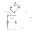
- FIG. 3 is a simplified illustration showing the trailer angle between the tractor and a conveyance.
- FIG. 4 is a simplified diagram illustrating an exemplary field in which an automated tractor can operate.
- FIG. 5 is a simplified state diagram illustrating various states of the automated vehicle in accordance with one or more embodiments.
- FIG. 6 is a simplified diagram illustrating a harvester.
- FIG. 7 is a simplified diagram illustrating varying load positions in a conveyance.
- FIG. 8 is a simplified diagram illustrating calculation of the tractor path in accordance with one or more embodiments.
- Various embodiments disclosed herein are directed to methods and systems for automatically driving and dynamically positioning a vehicle (referred to herein as a “first” vehicle) relative to another vehicle (referred to herein as a “second” vehicle).
- the first vehicle is towing a conveyance, and it is controlled such that the conveyance is positioned accurately relative to the second vehicle, while the second vehicle is in motion.
- the first vehicle is controlled to move between a designated parking area and a position relative to the second vehicle.
- the first vehicle is an automatically driven tractor 10
- the towed conveyance is a grain cart 12
- the second vehicle is a harvester 14
- the parking area contains a semi truck into which the grain cart 12 is offloaded after having been filled.
- the harvester 14 offloads harvested corn, soy, or other product into the grain cart 12 as the grain cart 12 is towed alongside the harvester 14 by the tractor 10 .
- the tractor 10 tows it to the parking area to be offloaded into the semi truck.
- the tractor 10 tows it back out to the harvester 14 , which has remained in motion, to begin taking offloaded product again.
- the second vehicle 14 which the first vehicle 10 is controlled to be positioned relative thereto, can be operated in various ways, including by a human driver inside the vehicle. Alternately, the second vehicle 14 can be tele-operated (i.e., remotely operated) by a human outside the vehicle or it can be driven entirely automatically.
- Various embodiments disclosed herein discuss the positioning of the towed conveyance 12 relative to the second vehicle 14 .
- techniques disclosed herein are also applicable to the case where the second vehicle 14 is also towing a conveyance, and the dynamic positioning of the first conveyance is relative to the second conveyance.
- the second vehicle 14 can tow a conveyance, and the dynamic positioning of the first vehicle 10 is relative to the conveyance of the second.
- neither vehicle tows a conveyance, and the first vehicle 10 is controlled such that it is dynamically positioned relative to the second vehicle 14 .
- FIG. 2 is a simplified block diagram illustrating components of the automated first vehicle 10 in accordance with one or more embodiments.
- the first vehicle 10 includes a vehicle drive system 16 or chassis for moving the vehicle.
- the first vehicle 10 also includes an obstacle detection system 18 including one or more range sensors for detecting obstacles 36 (shown in FIG. 4 ) in the vehicle travel path.
- the first vehicle 10 also includes a vehicle state property estimation system 20 comprising one or more sensors for estimating state properties of the vehicle. It further includes a microprocessor-based vehicle controller 22 , which receives inputs from the obstacle detection system 18 and the vehicle state property estimation system.
- the vehicle controller 22 also receives data on estimated state properties from the second vehicle 14 .
- the vehicle controller 22 controls operation of the drive system 16 and is programmed to maneuver the vehicle in a desired manner, including dynamically positioning the first vehicle 10 relative to the second vehicle 14 .
- the vehicle controller 22 is physically located within the body of the first vehicle 10 . It should be understood, however, that in other embodiments, the vehicle controller 22 , or portions of the controller, could be located outside of the first vehicle 10 . Such separation of physical location of the electronics and software for controlling the first vehicle 10 is contemplated herein. Moreover, while in the exemplary embodiments discussed herein indicate information is sent to or from the first vehicle 10 , that is intended to mean information sent to or from the vehicle controller 22 , wherever it may be physically located.
- the vehicle state property estimation system 20 in the first vehicle 10 estimates several state properties of the vehicle from one or more sensors.
- the second vehicle 14 includes a vehicle state property estimation system to estimate several state properties of that vehicle.
- State variables estimated for both vehicles include absolute position in some Earth-relative navigation system (e.g., latitude and longitude), speed, heading, and yaw rate (i.e., rate of change of heading).
- the angle between the vehicle 10 and any towed conveyance 12 e.g., between the tractor 10 and the grain cart 12 as illustrated in FIG. 3 ) is also estimated.
- a set of sensors for forward motion comprise a Global Positioning System (GPS) device with Real Time Kinematic (RTK) correction, which provide position and, when a vehicle is in motion, heading.
- the set of sensors can further include an inertial measurement unit (IMU), which provides measurements of linear acceleration and rotational velocity.
- IMU inertial measurement unit
- the set of sensors can also include sensors for odometry measurements of the tractor's wheels and steering angle. Other combinations of sensors are also possible for forward motion.
- an additional sensor is used, which directly or indirectly measures the angle between the vehicle 10 and the conveyance 12 .
- This additional sensor is used because reverse motion is generally unstable, and dynamic control techniques are performed using the sensor input.
- the desired state values can be estimated from the sensor data using an Unscented Kalman Filter (UKF), whose inputs are the sensor measurements and whose outputs are the state variables.
- ULF Unscented Kalman Filter
- Other state estimation methods could also be employed.
- Both vehicles need not use the same set of sensors.
- the harvester 14 could use the global, earth-relative sensors described above, while the tractor 10 could use sensors that directly ascertain its position relative to the harvester 14 in some local reference frame.
- Relative positioning is the responsibility of the automatic tractor 10 .
- the state estimates of the harvester 14 are continuously sent electronically to the tractor 10 to facilitate positioning.
- FIG. 4 is a simplified illustration of an exemplary field 24 on which the tractor 10 and harvester 14 can operate.
- the field 24 is defined by a field boundary 26 .
- the field 24 includes legal travel areas within the field boundary 26 .
- the tractor 10 is allowed to travel only in the legal travel areas.
- Legal travel areas can include a designated parking area 28 .
- the system operator may designate zero or more geographic regions of arbitrary shape to be parking areas.
- Legal travel areas can also include designated travel corridors 30 .
- the system operator can designate zero or more geographic regions of arbitrary shape to be travel corridors.
- Legal travel areas can also include previously traveled areas. If the second vehicle 14 travels over an area, that area is by default deemed to be a legal travel area. For instance, a harvester 14 harvests the crop and leaves a cleared area behind it. The harvester 14 regularly transmits newly-cleared path information to the tractor controller 22 so that the tractor 10 has an accurate representation of the harvested areas.
- the field boundary 26 can be designated by the system operator as an arbitrary boundary around the operating area. No area outside of that boundary can be a legal travel area.
- the system operator can also designate an arbitrary boundary 32 around zero or more obstacles. No area inside any obstacle boundary 32 can be a legal travel area.
- the obstacle detection system 18 in the first vehicle allows it to detect unanticipated obstacles 36 in the field 24 . While an obstacle 36 is detected, it designates an obstacle boundary 32 around the obstacle. This area within the obstacle boundary 32 is not a legal travel area.
- a long-distance path finding procedure is used to determine a legal path for the first vehicle 10 to follow to be at a desired position relative to the second vehicle 14 .
- a variety of algorithms and processes can be used for such long-distance path finding, including a standard A* or hybrid A* algorithm.
- the A* algorithms work from a discrete set of moves—that is, a discrete set of vehicle headings is considered at each step in the process.
- the area available for the path planning algorithms to use is determined from both the pre-surveyed paths in the field 24 (e.g., designated parking areas 28 , travel corridors 30 , field boundaries 26 , and obstacle boundaries 32 ) and area 34 that has been previously travelled by the harvester 14 .
- the algorithm for checking whether a path lies entirely inside legal travel areas can use a simplified polygon representation of the vehicle and the legal travel areas, and performs intersection-checking of the vehicle polygon with the various areas.
- the tractor 10 to reduce the frequency with which the tractor 10 has to “stop to think,” it runs a path planning algorithm tuned to run to conclusion quickly, but to give up relatively easily on any path. In order to find a path even in complex terrain, the tractor 10 simultaneously runs a copy of the path planning algorithm tuned to be very aggressive in trying to find a path. This ensures that if the quick path finder above fails, the tractor 10 can eventually think its way out of any solvable situation.
- the tractor 10 Upon receiving a STOP command 50 , the tractor 10 will slow to a halt along its currently planned path.
- the manner of stopping is intended to be as quick as possible while remaining subjectively comfortable for any human occupant of the tractor 10 .
- the tractor 10 When executing an EMERGENCY STOP operation 52 , the tractor 10 will attempt to halt as quickly as possible, e.g., by fully engaging the brakes and fully disengaging the clutch.
- the manner of stopping is intended to be immediate, without regard to the subjective comfort of any human occupant of the tractor 10 .
- the tractor 10 When executing a PARK operation 54 , the tractor 10 will perform long-distance path finding to find a legal path to the designated parking area 28 . If a path is found, the tractor 10 will travel using the long-distance path following process. If no path is found, the tractor 10 will perform a STOP operation 50 , returning to active motion when a legal PARK path is discovered.
- the tractor 10 Upon receiving FOLLOW command 56 , the tractor 10 will perform a FOLLOW operation to begin following the harvester 14 at a standoff distance. If the harvester 14 is not nearby when the operation starts, the tractor 10 will first transit from its current location to the harvester 14 via legal long-distance travel paths, using the long-distance path following process. If no legal path can be determined, the tractor 10 will begin a STOP operation 50 , returning to active motion when a legal FOLLOW path is discovered.
- the tractor 10 creates new plans to the current harvester position.
- the plan is made from a point in the tractor's future path. If an updated plan is found successfully, the remainder of the current plan is replaced with the new plan. This update and re-plan procedure continues indefinitely while the tractor 10 is in FOLLOW mode 56 .
- the tractor 10 Upon receiving an OFFLOAD command, the tractor 10 will perform an OFFLOAD operation 58 A, 58 B to take up a precisely-maintained position relative to the harvester 14 to support offload.
- the harvester 14 can include a lever arm 70 (shown in FIG. 6 ) for offloading material to the grain cart 12 .
- the system operator identifies a position relative to the harvester 14 , called the “lever arm position” or “spout position” 72 (shown in FIG. 6 ), and a position relative to the grain cart 12 , called the “load position” 74 (shown in FIG. 7 ).
- the system endeavors to keep the two positions co-located.
- the OFFLOAD process is comprised of two major steps.
- ROUGH POSITIONING 58 A the automatic tractor 10 tows the trailer 12 into a “roughly correct” position using the long-distance path finding and long-distance path following processes to get near the harvester 14 . If the tractor 10 cannot determine a legal path to an offload position, or if the tractor 10 is already in offload position, but the current legal path “dead ends,” it will perform a FOLLOW operation 56 until such time as a legal offload path can be found.
- the second step, FINE POSITIONING 58 B begins once the trailer 12 is in approximately the correct position, to bring it to the desired position, and to maintain that position, with the required accuracy.
- the tractor 10 uses the state information received from the harvester 14 to estimate the arc that the lever arm position will trace out, assuming that the current harvester yaw rate remains constant.
- a standard control algorithm known as “pure pursuit” can be used to determine the path that the grain cart should traverse in order to keep the load position 74 co-located with the spout position 72 .
- the harvester vehicle 14 may support more than one lever arm position.
- a harvester 14 may support offloading to the right or to the left sides.
- the load position 74 can be deliberately varied (as shown in FIG. 7 ) during operation, e.g., in order to maintain even fill of a grain cart 12 .
- the system operator may manually adjust the load position 74 during operations.
- the load position 74 may also optionally be set to automatically cycle from the front of the grain cart to the back.
- sensors such as load sensors or content-height sensors affixed to the grain cart at various points can be used to automatically guide the loading position 74 along the axis of the grain cart 12 to provide more even loading.
- the processes of the vehicle controller 22 described above may be implemented in software, hardware, firmware, or any combination thereof.
- the processes are preferably implemented in one or more computer programs executing on the vehicle controller 22 .
- Each computer program can be a set of instructions (program code) in a code module resident in the random access memory of the controller 22 .
- the set of instructions may be stored in another computer memory (e.g., in a hard disk drive, or in a removable memory such as an optical disk, external hard drive, memory card, or flash drive) or stored on another computer system and downloaded via the Internet or other network.
Abstract
Description
Claims (18)
Priority Applications (1)
| Application Number | Priority Date | Filing Date | Title |
|---|---|---|---|
| US14/026,549 US8874355B2 (en) | 2011-10-25 | 2013-09-13 | Method and system for dynamically positioning a vehicle relative to another vehicle in motion |
Applications Claiming Priority (2)
| Application Number | Priority Date | Filing Date | Title |
|---|---|---|---|
| US13/281,012 US8589013B2 (en) | 2011-10-25 | 2011-10-25 | Method and system for dynamically positioning a vehicle relative to another vehicle in motion |
| US14/026,549 US8874355B2 (en) | 2011-10-25 | 2013-09-13 | Method and system for dynamically positioning a vehicle relative to another vehicle in motion |
Related Parent Applications (1)
| Application Number | Title | Priority Date | Filing Date |
|---|---|---|---|
| US13/281,012 Division US8589013B2 (en) | 2011-10-25 | 2011-10-25 | Method and system for dynamically positioning a vehicle relative to another vehicle in motion |
Publications (2)
| Publication Number | Publication Date |
|---|---|
| US20140012489A1 US20140012489A1 (en) | 2014-01-09 |
| US8874355B2 true US8874355B2 (en) | 2014-10-28 |
Family
ID=48136636
Family Applications (2)
| Application Number | Title | Priority Date | Filing Date |
|---|---|---|---|
| US13/281,012 Active 2031-12-09 US8589013B2 (en) | 2011-10-25 | 2011-10-25 | Method and system for dynamically positioning a vehicle relative to another vehicle in motion |
| US14/026,549 Active US8874355B2 (en) | 2011-10-25 | 2013-09-13 | Method and system for dynamically positioning a vehicle relative to another vehicle in motion |
Family Applications Before (1)
| Application Number | Title | Priority Date | Filing Date |
|---|---|---|---|
| US13/281,012 Active 2031-12-09 US8589013B2 (en) | 2011-10-25 | 2011-10-25 | Method and system for dynamically positioning a vehicle relative to another vehicle in motion |
Country Status (1)
| Country | Link |
|---|---|
| US (2) | US8589013B2 (en) |
Cited By (1)
| Publication number | Priority date | Publication date | Assignee | Title |
|---|---|---|---|---|
| US11882799B2 (en) | 2020-10-30 | 2024-01-30 | Lindsay Corporation | System and method for coordinating movement of agricultural machines and irrigation systems |
Families Citing this family (41)
| Publication number | Priority date | Publication date | Assignee | Title |
|---|---|---|---|---|
| US8386129B2 (en) | 2009-01-17 | 2013-02-26 | Hemipshere GPS, LLC | Raster-based contour swathing for guidance and variable-rate chemical application |
| US8803735B2 (en) | 2010-11-19 | 2014-08-12 | Agjunction Llc | Portable base station network for local differential GNSS corrections |
| US20140083071A1 (en) * | 2012-09-25 | 2014-03-27 | Ii Jeffrey Fay | Active steering windrow shields |
| US10417674B2 (en) | 2013-03-14 | 2019-09-17 | Bill.Com, Llc | System and method for sharing transaction information by object tracking of inter-entity transactions and news streams |
| US9945957B2 (en) | 2013-03-14 | 2018-04-17 | Agjunction Llc | Machine control system and method |
| US9185845B2 (en) | 2013-03-15 | 2015-11-17 | Unverferth Manufacturing Company, Inc. | Method for controlling unload of a mobile farm implement |
| US9272853B2 (en) | 2013-03-15 | 2016-03-01 | Unverferth Manufacturing Company, Inc. | Weight-based chute control for a farm implement |
| US9187259B2 (en) | 2013-03-15 | 2015-11-17 | Unverferth Manufacturing Company, Inc. | Method for controlling an unload operation on a mobile farm implement |
| US10572921B2 (en) | 2013-07-03 | 2020-02-25 | Bill.Com, Llc | System and method for enhanced access and control for connecting entities and effecting payments in a commercially oriented entity network |
| US9733643B2 (en) | 2013-12-20 | 2017-08-15 | Agjunction Llc | Hydraulic interrupter safety system and method |
| US10246180B2 (en) | 2014-05-20 | 2019-04-02 | Sikorsky Aircraft Corporation | Cooperative perception and state estimation for vehicles with compromised sensor systems |
| BR102015013228B1 (en) * | 2014-06-13 | 2020-11-24 | Cnh Industrial America Llc | CONTROL SYSTEM AND METHOD FOR AN AGRICULTURAL VEHICLE |
| DE102014224099A1 (en) * | 2014-11-26 | 2016-06-02 | Robert Bosch Gmbh | Method and device for operating multiple vehicles |
| US9857478B2 (en) | 2015-01-27 | 2018-01-02 | Agjunction Llc | Apparatus and method to mount steering actuator |
| US9904290B2 (en) * | 2015-04-19 | 2018-02-27 | Deere & Company | Geometry-based monitoring and control of coupled mobile machines |
| US10241215B2 (en) | 2015-11-19 | 2019-03-26 | Agjunction Llc | Sensor alignment calibration |
| US10239555B2 (en) | 2015-11-19 | 2019-03-26 | Agjunction Llc | Single-mode implement steering |
| US10266201B2 (en) | 2015-11-19 | 2019-04-23 | Agjunction Llc | K-turn path controller |
| US10890922B2 (en) | 2015-11-19 | 2021-01-12 | Agjunction Llc | Automated multi-vehicle alignment steering |
| US11180189B2 (en) | 2015-11-19 | 2021-11-23 | Agjunction Llc | Automated reverse implement parking |
| US10845375B2 (en) | 2016-02-19 | 2020-11-24 | Agjunction Llc | Thermal stabilization of inertial measurement units |
| WO2017180521A2 (en) | 2016-04-12 | 2017-10-19 | Agjunction Llc | Line acquisition path generation using curvature profiles |
| US10152891B2 (en) * | 2016-05-02 | 2018-12-11 | Cnh Industrial America Llc | System for avoiding collisions between autonomous vehicles conducting agricultural operations |
| US10143126B2 (en) | 2016-06-10 | 2018-12-04 | Cnh Industrial America Llc | Planning and control of autonomous agricultural operations |
| US10251329B2 (en) | 2016-06-10 | 2019-04-09 | Cnh Industrial Canada, Ltd. | Planning and control of autonomous agricultural operations |
| BR112019006526A2 (en) | 2016-10-03 | 2019-06-25 | Agjunction Llc | control system to gather data from different sensors and determine a vehicle orientation and computer program to calculate a vehicle direction |
| WO2018075397A1 (en) | 2016-10-17 | 2018-04-26 | Agjunction Llc | An actuator for turning a steering wheel in automatic steering systems |
| US10822017B2 (en) | 2016-10-17 | 2020-11-03 | Agjunction Llc | Integrated auto-steer system for vehicle |
| SG10201609375XA (en) * | 2016-11-09 | 2018-06-28 | Cyclect Electrical Eng Pte Ltd | Vehicle, system and method for remote convoying |
| CN106598055B (en) * | 2017-01-19 | 2019-05-10 | 北京智行者科技有限公司 | A kind of intelligent vehicle local paths planning method and its device, vehicle |
| EP3570652B1 (en) | 2017-01-19 | 2022-12-21 | Agjunction LLC | Low cost implement positioning |
| WO2018236853A1 (en) | 2017-06-22 | 2018-12-27 | Agjunction Llc | 3-d image system for vehicle control |
| EP3704443A1 (en) | 2017-10-31 | 2020-09-09 | Agjunction LLC | Three-dimensional terrain mapping |
| CN108363393B (en) | 2018-02-05 | 2019-09-27 | 腾讯科技(深圳)有限公司 | A kind of smart motion equipment and its air navigation aid and storage medium |
| CN108073176B (en) * | 2018-02-10 | 2020-08-18 | 西安交通大学 | Improved D star Lite vehicle dynamic path planning method |
| US11167743B2 (en) | 2018-04-03 | 2021-11-09 | AgJunction, LLC | Automatic pitch mounting compensation in an automatic steering system |
| CN108921961B (en) * | 2018-07-04 | 2020-10-02 | 河南师范大学 | Intelligent charging system based on motor control |
| AU2019339489A1 (en) | 2018-09-14 | 2021-02-18 | Agjunction Llc | Integrated GNSS and steering for agricultural guidance systems |
| WO2020056283A1 (en) | 2018-09-14 | 2020-03-19 | Agjunction Llc | Using non-real-time computers for agricultural guidance systems |
| CA3145883A1 (en) | 2019-07-31 | 2021-02-04 | Agjunction Llc | Integrated vehicle guidance and steering system |
| US20210365036A1 (en) * | 2020-05-22 | 2021-11-25 | Cnh Industrial America Llc | Localized obstacle avoidance for optimal v2v path planning |
Citations (80)
| Publication number | Priority date | Publication date | Assignee | Title |
|---|---|---|---|---|
| US3429062A (en) | 1966-03-11 | 1969-02-25 | Arthur J Nelson | Deep water harvesting system |
| US3889796A (en) | 1974-01-24 | 1975-06-17 | Idaho Res Found | Harvester boom control |
| US5204814A (en) | 1990-11-13 | 1993-04-20 | Mobot, Inc. | Autonomous lawn mower |
| US5684476A (en) | 1993-12-30 | 1997-11-04 | Concord, Inc. | Field navigation system |
| US5987383A (en) | 1997-04-28 | 1999-11-16 | Trimble Navigation | Form line following guidance system |
| US6076025A (en) | 1997-01-29 | 2000-06-13 | Honda Giken Kogyo K.K. | Mobile robot steering method and control device |
| US6088644A (en) | 1998-08-12 | 2000-07-11 | Caterpillar Inc. | Method and apparatus for determining a path to be traversed by a mobile machine |
| US6141614A (en) | 1998-07-16 | 2000-10-31 | Caterpillar Inc. | Computer-aided farming system and method |
| US6151539A (en) | 1997-11-03 | 2000-11-21 | Volkswagen Ag | Autonomous vehicle arrangement and method for controlling an autonomous vehicle |
| US6205381B1 (en) | 1999-03-26 | 2001-03-20 | Caterpillar Inc. | Method and apparatus for providing autoguidance for multiple agricultural machines |
| US6377889B1 (en) | 2000-10-13 | 2002-04-23 | Trimble Navigation Limited | Non-linear method of guiding to arbitrary curves with adaptive feedback |
| US6431576B1 (en) | 1999-04-28 | 2002-08-13 | Deere & Company | System for steering towed implement in response to, or independently of, steering of towing vehicle |
| US6434462B1 (en) | 2001-06-28 | 2002-08-13 | Deere & Company | GPS control of a tractor-towed implement |
| US6501422B1 (en) | 1998-08-19 | 2002-12-31 | Trimble Navigation, Ltd. | Precise parallel swathing guidance via satellite navigation and tilt measurement |
| US6539303B2 (en) | 2000-12-08 | 2003-03-25 | Mcclure John A. | GPS derived swathing guidance system |
| US6615108B1 (en) | 1998-05-11 | 2003-09-02 | F. Robotics Acquisitions Ltd. | Area coverage with an autonomous robot |
| US6643576B1 (en) | 2000-11-15 | 2003-11-04 | Integrinautics Corporation | Rapid adjustment of trajectories for land vehicles |
| US6804587B1 (en) | 2000-11-15 | 2004-10-12 | Integrinautics Corporation | Adjustment of vehicle-implement trajectories to compensate for lateral implement offset |
| US6804597B1 (en) | 2003-07-14 | 2004-10-12 | New Holland North America, Inc. | Automatic guidance system for towed farm implements |
| US6865465B2 (en) | 2002-05-06 | 2005-03-08 | Csi Wireless, Inc. | Method and system for implement steering for agricultural vehicles |
| US20050053451A1 (en) * | 1999-02-11 | 2005-03-10 | Pierre Gagnon | Vehicle loading and unloading system |
| US6907336B2 (en) | 2003-03-31 | 2005-06-14 | Deere & Company | Method and system for efficiently traversing an area with a work vehicle |
| US6990399B2 (en) | 2002-10-31 | 2006-01-24 | Cnh America Llc | Agricultural utility vehicle and method of controlling same |
| US7010425B2 (en) | 2003-03-31 | 2006-03-07 | Deere & Company | Path planner and a method for planning a path of a work vehicle |
| US7054731B1 (en) | 2003-08-29 | 2006-05-30 | Trimble Navigation Limited | Farm implement guidance method and apparatus |
| US20060156703A1 (en) * | 2003-03-05 | 2006-07-20 | Dillon Ben N | Articulated harvester and method for converting a harvester and towed grain trailer into an articulated harvester |
| US20060178820A1 (en) | 2005-02-04 | 2006-08-10 | Novariant, Inc. | System and method for guiding an agricultural vehicle through a recorded template of guide paths |
| US20060175541A1 (en) | 2005-02-04 | 2006-08-10 | Novariant, Inc. | System and method for interactive selection of agricultural vehicle guide paths through a graphical user interface other than moving the vehicle |
| US20060178823A1 (en) | 2005-02-04 | 2006-08-10 | Novariant, Inc. | System and method for propagating agricultural vehicle guidance paths that have varying curvature along their length |
| US20060178825A1 (en) | 2005-02-04 | 2006-08-10 | Novariant, Inc. | System and method for interactive selection of agricultural vehicle guide paths with varying curvature along their length |
| US7100725B2 (en) | 2002-08-30 | 2006-09-05 | Aethon | Robotic cart pulling vehicle |
| US7142956B2 (en) | 2004-03-19 | 2006-11-28 | Hemisphere Gps Llc | Automatic steering system and method |
| US7162348B2 (en) | 2002-12-11 | 2007-01-09 | Hemisphere Gps Llc | Articulated equipment position control system and method |
| US7173391B2 (en) | 2001-06-12 | 2007-02-06 | Irobot Corporation | Method and system for multi-mode coverage for an autonomous robot |
| US7188015B2 (en) | 2004-07-14 | 2007-03-06 | Trimble Navigation Limited | Method and system for controlling a mobile machine |
| US7191061B2 (en) | 2003-04-17 | 2007-03-13 | Battelle Energy Alliance, Llc | Auto-steering apparatus and method |
| US7228214B2 (en) | 2003-03-31 | 2007-06-05 | Deere & Company | Path planner and method for planning a path plan having a spiral component |
| US20070233374A1 (en) | 2006-03-30 | 2007-10-04 | Norbert Diekhans | Method for creating a route plan for agricultural machine systems |
| US7317977B2 (en) | 2004-08-23 | 2008-01-08 | Topcon Positioning Systems, Inc. | Dynamic stabilization and control of an earthmoving machine |
| US20080009985A1 (en) * | 2005-09-14 | 2008-01-10 | Plishner Paul J | Semi-autonomous guidance system for a vehicle |
| US7350343B2 (en) | 2001-06-16 | 2008-04-01 | Deere & Company | System for automatically steering a utility vehicle |
| US7363154B2 (en) | 2005-10-12 | 2008-04-22 | Trimble Navigation Limited | Method and system for determining the path of a mobile machine |
| US7388343B2 (en) | 2001-06-12 | 2008-06-17 | Irobot Corporation | Method and system for multi-mode coverage for an autonomous robot |
| US20080167817A1 (en) * | 2007-01-06 | 2008-07-10 | Transbotics Corporation | Automated cargo loading systems and methods |
| US7437230B2 (en) | 2003-03-20 | 2008-10-14 | Hemisphere Gps Llc | Satellite based vehicle guidance control in straight and contour modes |
| US20080306628A1 (en) | 2007-06-08 | 2008-12-11 | Honda Motor Co., Ltd. | Multi-Modal Push Planner for Humanoid Robots |
| US7490678B2 (en) | 2005-04-21 | 2009-02-17 | A.I.L., Inc. | GPS controlled guidance system for farm tractor/implement combination |
| US7502678B2 (en) | 2006-04-21 | 2009-03-10 | Claas Selbstfahrende Erntemaschinen Gmbh | Method for controlling an agricultural machine system |
| US7509199B2 (en) | 2006-06-30 | 2009-03-24 | Deere & Company | System and method for calculating instantaneous placement corrections to achieve towed implement placement on curved paths |
| US7580783B2 (en) | 2004-12-29 | 2009-08-25 | Cnh America Llc | Correction in position with hitch position sensor |
| US20090228166A1 (en) * | 2006-01-18 | 2009-09-10 | I-Guide, Llc | Robotic Vehicle Controller |
| US7593798B2 (en) | 2003-10-30 | 2009-09-22 | Deere & Company | Vehicular guidance system having compensation for variations in ground elevation |
| US7623952B2 (en) | 2005-04-21 | 2009-11-24 | A.I.L., Inc. | GPS controlled guidance system for farm tractor/implement combination |
| US20100066517A1 (en) | 2008-09-05 | 2010-03-18 | Posselius John H | Determination of relative position of two relatively movable elements |
| US7689354B2 (en) | 2003-03-20 | 2010-03-30 | Hemisphere Gps Llc | Adaptive guidance system and method |
| US7689356B2 (en) | 2006-10-27 | 2010-03-30 | Cnh America Llc | Method and apparatus for creating curved swath patterns for farm machinery |
| US7693653B2 (en) | 2004-03-24 | 2010-04-06 | Bbn Technologies Corp | Vehicle routing and path planning |
| US7706948B2 (en) | 2007-03-02 | 2010-04-27 | Cnh America Llc | Method for creating spiral swaths for irregular field boundaries |
| US7715966B2 (en) | 2007-03-02 | 2010-05-11 | Cnh America Llc | Method for creating spiral swath patterns for convex polygon shaped field boundaries |
| US7715979B2 (en) | 2006-10-27 | 2010-05-11 | Cnh America Llc | Nudge compensation for curved swath paths |
| US7729834B2 (en) | 2006-01-18 | 2010-06-01 | Claas Selbstfahrende Erntemaschinen Gmbh | Method for creating reference driving tracks for agricultural working machines |
| US7734387B1 (en) | 2006-03-31 | 2010-06-08 | Rockwell Collins, Inc. | Motion planner for unmanned ground vehicles traversing at high speeds in partially known environments |
| US7737878B2 (en) | 2007-07-09 | 2010-06-15 | Eads Deutschland Gmbh | Collision and conflict avoidance system for autonomous unmanned air vehicles (UAVs) |
| US7742860B2 (en) | 2004-06-03 | 2010-06-22 | Claas Selbstfahrende Erntemaschinen Gmbh | Route planning system and method for agricultural working machines |
| US7747370B2 (en) | 2007-04-03 | 2010-06-29 | Cnh America Llc | Method for creating end of row turns for agricultural vehicles |
| US20100174435A1 (en) | 2009-01-07 | 2010-07-08 | Samsung Electronics Co., Ltd. | Path planning apparatus of robot and method thereof |
| US7756624B2 (en) | 2005-12-08 | 2010-07-13 | Claas Selbstfahrende Erntemaschinen Gmbh | Route planning system for agricultural working machines |
| US7818120B2 (en) | 2006-11-30 | 2010-10-19 | Raytheon Company | Route-planning interactive navigation system and method |
| US20100274452A1 (en) | 2009-04-28 | 2010-10-28 | Ringwald Justin R | Grain transfer control system and method |
| US7835832B2 (en) | 2007-01-05 | 2010-11-16 | Hemisphere Gps Llc | Vehicle control system |
| US20100292835A1 (en) | 2009-05-15 | 2010-11-18 | Honda Research Institute Europe Gmbh | Autonomous robots with planning in unpredictable, dynamic and complex environments |
| US7844378B2 (en) | 2006-10-05 | 2010-11-30 | Trimble Navigation Limited | Farm apparatus having implement sidehill drift compensation |
| US7860628B2 (en) | 2005-06-09 | 2010-12-28 | Trimble Navigation Limited | System for guiding a farm implement between swaths |
| US7873437B2 (en) | 2003-02-14 | 2011-01-18 | Dyson Technology Limited | Autonomous machine |
| US20110035051A1 (en) | 2009-08-10 | 2011-02-10 | Samsung Electronics Co., Ltd | Path planning apparatus and method for robot |
| US20110035050A1 (en) | 2009-08-10 | 2011-02-10 | Samsung Electronics Co., Ltd. | Method and apparatus to plan motion path of robot |
| US8132659B2 (en) | 2008-07-15 | 2012-03-13 | Deere & Company | Tractor mounted unloading conveyor |
| US20120096824A1 (en) | 2010-10-25 | 2012-04-26 | John David Burger | Tugger/Accumulator For Use With An Agricultural Biomass Harvester |
| US8186497B2 (en) | 2009-10-13 | 2012-05-29 | Deere & Company | Unloading conveyor suspension system |
| US20120302299A1 (en) | 2011-05-25 | 2012-11-29 | Willi Behnke | Harvesting Device |
-
2011
- 2011-10-25 US US13/281,012 patent/US8589013B2/en active Active
-
2013
- 2013-09-13 US US14/026,549 patent/US8874355B2/en active Active
Patent Citations (94)
| Publication number | Priority date | Publication date | Assignee | Title |
|---|---|---|---|---|
| US3429062A (en) | 1966-03-11 | 1969-02-25 | Arthur J Nelson | Deep water harvesting system |
| US3889796A (en) | 1974-01-24 | 1975-06-17 | Idaho Res Found | Harvester boom control |
| US5204814A (en) | 1990-11-13 | 1993-04-20 | Mobot, Inc. | Autonomous lawn mower |
| US5684476A (en) | 1993-12-30 | 1997-11-04 | Concord, Inc. | Field navigation system |
| US6076025A (en) | 1997-01-29 | 2000-06-13 | Honda Giken Kogyo K.K. | Mobile robot steering method and control device |
| US5987383A (en) | 1997-04-28 | 1999-11-16 | Trimble Navigation | Form line following guidance system |
| US5987383C1 (en) | 1997-04-28 | 2006-06-13 | Trimble Navigation Ltd | Form line following guidance system |
| US6151539A (en) | 1997-11-03 | 2000-11-21 | Volkswagen Ag | Autonomous vehicle arrangement and method for controlling an autonomous vehicle |
| US7155309B2 (en) | 1998-05-11 | 2006-12-26 | F Robotics Ltd. | Area coverage with an autonomous robot |
| US7349759B2 (en) | 1998-05-11 | 2008-03-25 | F Robotics Acquisitions Ltd. | Area coverage with an autonomous robot |
| US6885912B2 (en) | 1998-05-11 | 2005-04-26 | F Robotics Acquistions Ltd. | Area coverage with an autonomous robot |
| US6615108B1 (en) | 1998-05-11 | 2003-09-02 | F. Robotics Acquisitions Ltd. | Area coverage with an autonomous robot |
| US6141614A (en) | 1998-07-16 | 2000-10-31 | Caterpillar Inc. | Computer-aided farming system and method |
| US6088644A (en) | 1998-08-12 | 2000-07-11 | Caterpillar Inc. | Method and apparatus for determining a path to be traversed by a mobile machine |
| US6703973B1 (en) | 1998-08-19 | 2004-03-09 | Trimble Navigation, Ltd. | Guiding vehicle in adjacent swaths across terrain via satellite navigation and tilt measurement |
| US6501422B1 (en) | 1998-08-19 | 2002-12-31 | Trimble Navigation, Ltd. | Precise parallel swathing guidance via satellite navigation and tilt measurement |
| US20050053451A1 (en) * | 1999-02-11 | 2005-03-10 | Pierre Gagnon | Vehicle loading and unloading system |
| US6205381B1 (en) | 1999-03-26 | 2001-03-20 | Caterpillar Inc. | Method and apparatus for providing autoguidance for multiple agricultural machines |
| US6431576B1 (en) | 1999-04-28 | 2002-08-13 | Deere & Company | System for steering towed implement in response to, or independently of, steering of towing vehicle |
| US6377889B1 (en) | 2000-10-13 | 2002-04-23 | Trimble Navigation Limited | Non-linear method of guiding to arbitrary curves with adaptive feedback |
| US6643576B1 (en) | 2000-11-15 | 2003-11-04 | Integrinautics Corporation | Rapid adjustment of trajectories for land vehicles |
| US6804587B1 (en) | 2000-11-15 | 2004-10-12 | Integrinautics Corporation | Adjustment of vehicle-implement trajectories to compensate for lateral implement offset |
| US6539303B2 (en) | 2000-12-08 | 2003-03-25 | Mcclure John A. | GPS derived swathing guidance system |
| US7173391B2 (en) | 2001-06-12 | 2007-02-06 | Irobot Corporation | Method and system for multi-mode coverage for an autonomous robot |
| US7429843B2 (en) | 2001-06-12 | 2008-09-30 | Irobot Corporation | Method and system for multi-mode coverage for an autonomous robot |
| US7388343B2 (en) | 2001-06-12 | 2008-06-17 | Irobot Corporation | Method and system for multi-mode coverage for an autonomous robot |
| US7350343B2 (en) | 2001-06-16 | 2008-04-01 | Deere & Company | System for automatically steering a utility vehicle |
| US6434462B1 (en) | 2001-06-28 | 2002-08-13 | Deere & Company | GPS control of a tractor-towed implement |
| US6865465B2 (en) | 2002-05-06 | 2005-03-08 | Csi Wireless, Inc. | Method and system for implement steering for agricultural vehicles |
| US7100725B2 (en) | 2002-08-30 | 2006-09-05 | Aethon | Robotic cart pulling vehicle |
| US7431115B2 (en) | 2002-08-30 | 2008-10-07 | Aethon, Inc. | Robotic cart pulling vehicle |
| US6990399B2 (en) | 2002-10-31 | 2006-01-24 | Cnh America Llc | Agricultural utility vehicle and method of controlling same |
| US7373231B2 (en) | 2002-12-11 | 2008-05-13 | Hemisphere Gps Llc | Articulated equipment position control system and method |
| US7162348B2 (en) | 2002-12-11 | 2007-01-09 | Hemisphere Gps Llc | Articulated equipment position control system and method |
| US7873437B2 (en) | 2003-02-14 | 2011-01-18 | Dyson Technology Limited | Autonomous machine |
| US20060156703A1 (en) * | 2003-03-05 | 2006-07-20 | Dillon Ben N | Articulated harvester and method for converting a harvester and towed grain trailer into an articulated harvester |
| US7437230B2 (en) | 2003-03-20 | 2008-10-14 | Hemisphere Gps Llc | Satellite based vehicle guidance control in straight and contour modes |
| US7689354B2 (en) | 2003-03-20 | 2010-03-30 | Hemisphere Gps Llc | Adaptive guidance system and method |
| US7228214B2 (en) | 2003-03-31 | 2007-06-05 | Deere & Company | Path planner and method for planning a path plan having a spiral component |
| US7010425B2 (en) | 2003-03-31 | 2006-03-07 | Deere & Company | Path planner and a method for planning a path of a work vehicle |
| US6907336B2 (en) | 2003-03-31 | 2005-06-14 | Deere & Company | Method and system for efficiently traversing an area with a work vehicle |
| US7191061B2 (en) | 2003-04-17 | 2007-03-13 | Battelle Energy Alliance, Llc | Auto-steering apparatus and method |
| US6804597B1 (en) | 2003-07-14 | 2004-10-12 | New Holland North America, Inc. | Automatic guidance system for towed farm implements |
| US7383114B1 (en) | 2003-08-29 | 2008-06-03 | Trimble Navigation Limited | Method and apparatus for steering a farm implement to a path |
| US7054731B1 (en) | 2003-08-29 | 2006-05-30 | Trimble Navigation Limited | Farm implement guidance method and apparatus |
| US7593798B2 (en) | 2003-10-30 | 2009-09-22 | Deere & Company | Vehicular guidance system having compensation for variations in ground elevation |
| US7844380B2 (en) | 2003-10-30 | 2010-11-30 | Deere & Company | Vehicular guidance system having compensation for variations in ground elevation |
| US7142956B2 (en) | 2004-03-19 | 2006-11-28 | Hemisphere Gps Llc | Automatic steering system and method |
| US7693653B2 (en) | 2004-03-24 | 2010-04-06 | Bbn Technologies Corp | Vehicle routing and path planning |
| US7742860B2 (en) | 2004-06-03 | 2010-06-22 | Claas Selbstfahrende Erntemaschinen Gmbh | Route planning system and method for agricultural working machines |
| US7263422B2 (en) | 2004-07-14 | 2007-08-28 | Trimble Navigation Limited | Method and system for controlling a mobile machine |
| US7188015B2 (en) | 2004-07-14 | 2007-03-06 | Trimble Navigation Limited | Method and system for controlling a mobile machine |
| US7317977B2 (en) | 2004-08-23 | 2008-01-08 | Topcon Positioning Systems, Inc. | Dynamic stabilization and control of an earthmoving machine |
| US7580783B2 (en) | 2004-12-29 | 2009-08-25 | Cnh America Llc | Correction in position with hitch position sensor |
| US20060175541A1 (en) | 2005-02-04 | 2006-08-10 | Novariant, Inc. | System and method for interactive selection of agricultural vehicle guide paths through a graphical user interface other than moving the vehicle |
| US7451030B2 (en) | 2005-02-04 | 2008-11-11 | Novariant, Inc. | System and method for interactive selection and determination of agricultural vehicle guide paths offset from each other with varying curvature along their length |
| US20060178823A1 (en) | 2005-02-04 | 2006-08-10 | Novariant, Inc. | System and method for propagating agricultural vehicle guidance paths that have varying curvature along their length |
| US20060178820A1 (en) | 2005-02-04 | 2006-08-10 | Novariant, Inc. | System and method for guiding an agricultural vehicle through a recorded template of guide paths |
| US20060178825A1 (en) | 2005-02-04 | 2006-08-10 | Novariant, Inc. | System and method for interactive selection of agricultural vehicle guide paths with varying curvature along their length |
| US7256388B2 (en) | 2005-02-04 | 2007-08-14 | Novariant, Inc. | System and method for interactive selection of agricultural vehicle guide paths through a graphical user interface other than moving the vehicle |
| US7490678B2 (en) | 2005-04-21 | 2009-02-17 | A.I.L., Inc. | GPS controlled guidance system for farm tractor/implement combination |
| US7623952B2 (en) | 2005-04-21 | 2009-11-24 | A.I.L., Inc. | GPS controlled guidance system for farm tractor/implement combination |
| US7860628B2 (en) | 2005-06-09 | 2010-12-28 | Trimble Navigation Limited | System for guiding a farm implement between swaths |
| US20080009985A1 (en) * | 2005-09-14 | 2008-01-10 | Plishner Paul J | Semi-autonomous guidance system for a vehicle |
| US7363154B2 (en) | 2005-10-12 | 2008-04-22 | Trimble Navigation Limited | Method and system for determining the path of a mobile machine |
| US7756624B2 (en) | 2005-12-08 | 2010-07-13 | Claas Selbstfahrende Erntemaschinen Gmbh | Route planning system for agricultural working machines |
| US20090228166A1 (en) * | 2006-01-18 | 2009-09-10 | I-Guide, Llc | Robotic Vehicle Controller |
| US7729834B2 (en) | 2006-01-18 | 2010-06-01 | Claas Selbstfahrende Erntemaschinen Gmbh | Method for creating reference driving tracks for agricultural working machines |
| US20070233374A1 (en) | 2006-03-30 | 2007-10-04 | Norbert Diekhans | Method for creating a route plan for agricultural machine systems |
| US7734387B1 (en) | 2006-03-31 | 2010-06-08 | Rockwell Collins, Inc. | Motion planner for unmanned ground vehicles traversing at high speeds in partially known environments |
| US7502678B2 (en) | 2006-04-21 | 2009-03-10 | Claas Selbstfahrende Erntemaschinen Gmbh | Method for controlling an agricultural machine system |
| US7509199B2 (en) | 2006-06-30 | 2009-03-24 | Deere & Company | System and method for calculating instantaneous placement corrections to achieve towed implement placement on curved paths |
| US7844378B2 (en) | 2006-10-05 | 2010-11-30 | Trimble Navigation Limited | Farm apparatus having implement sidehill drift compensation |
| US7715979B2 (en) | 2006-10-27 | 2010-05-11 | Cnh America Llc | Nudge compensation for curved swath paths |
| US7689356B2 (en) | 2006-10-27 | 2010-03-30 | Cnh America Llc | Method and apparatus for creating curved swath patterns for farm machinery |
| US7818120B2 (en) | 2006-11-30 | 2010-10-19 | Raytheon Company | Route-planning interactive navigation system and method |
| US7835832B2 (en) | 2007-01-05 | 2010-11-16 | Hemisphere Gps Llc | Vehicle control system |
| US20080167817A1 (en) * | 2007-01-06 | 2008-07-10 | Transbotics Corporation | Automated cargo loading systems and methods |
| US7706948B2 (en) | 2007-03-02 | 2010-04-27 | Cnh America Llc | Method for creating spiral swaths for irregular field boundaries |
| US7715966B2 (en) | 2007-03-02 | 2010-05-11 | Cnh America Llc | Method for creating spiral swath patterns for convex polygon shaped field boundaries |
| US7877182B2 (en) | 2007-03-02 | 2011-01-25 | Cnh America Llc | Method for creating spiral swath patterns for convex polygon shaped field boundaries |
| US7747370B2 (en) | 2007-04-03 | 2010-06-29 | Cnh America Llc | Method for creating end of row turns for agricultural vehicles |
| US20080306628A1 (en) | 2007-06-08 | 2008-12-11 | Honda Motor Co., Ltd. | Multi-Modal Push Planner for Humanoid Robots |
| US7737878B2 (en) | 2007-07-09 | 2010-06-15 | Eads Deutschland Gmbh | Collision and conflict avoidance system for autonomous unmanned air vehicles (UAVs) |
| US8132659B2 (en) | 2008-07-15 | 2012-03-13 | Deere & Company | Tractor mounted unloading conveyor |
| US20100066517A1 (en) | 2008-09-05 | 2010-03-18 | Posselius John H | Determination of relative position of two relatively movable elements |
| US20100174435A1 (en) | 2009-01-07 | 2010-07-08 | Samsung Electronics Co., Ltd. | Path planning apparatus of robot and method thereof |
| US20100274452A1 (en) | 2009-04-28 | 2010-10-28 | Ringwald Justin R | Grain transfer control system and method |
| US20100292835A1 (en) | 2009-05-15 | 2010-11-18 | Honda Research Institute Europe Gmbh | Autonomous robots with planning in unpredictable, dynamic and complex environments |
| US20110035050A1 (en) | 2009-08-10 | 2011-02-10 | Samsung Electronics Co., Ltd. | Method and apparatus to plan motion path of robot |
| US20110035051A1 (en) | 2009-08-10 | 2011-02-10 | Samsung Electronics Co., Ltd | Path planning apparatus and method for robot |
| US8186497B2 (en) | 2009-10-13 | 2012-05-29 | Deere & Company | Unloading conveyor suspension system |
| US20120096824A1 (en) | 2010-10-25 | 2012-04-26 | John David Burger | Tugger/Accumulator For Use With An Agricultural Biomass Harvester |
| US20120302299A1 (en) | 2011-05-25 | 2012-11-29 | Willi Behnke | Harvesting Device |
Cited By (1)
| Publication number | Priority date | Publication date | Assignee | Title |
|---|---|---|---|---|
| US11882799B2 (en) | 2020-10-30 | 2024-01-30 | Lindsay Corporation | System and method for coordinating movement of agricultural machines and irrigation systems |
Also Published As
| Publication number | Publication date |
|---|---|
| US20140012489A1 (en) | 2014-01-09 |
| US8589013B2 (en) | 2013-11-19 |
| US20130103249A1 (en) | 2013-04-25 |
Similar Documents
| Publication | Publication Date | Title |
|---|---|---|
| US8874355B2 (en) | Method and system for dynamically positioning a vehicle relative to another vehicle in motion | |
| US9188986B2 (en) | Computer-implemented method and system for dynamically positioning a vehicle relative to another vehicle in motion for on-the-fly offloading operations | |
| US10989562B2 (en) | Systems and methods for annotating maps to improve sensor calibration | |
| US8645015B2 (en) | Semiautomatic parking machine | |
| US10031525B2 (en) | Swath tracking system for an off-road vehicle | |
| AU2016268034B2 (en) | Systems and methods for materials handling vehicle odometry calibration | |
| CN112298353B (en) | System and method for calibrating steering wheel neutral position | |
| US9014901B2 (en) | System and method for trajectory control of a transport vehicle used with a harvester | |
| US10046803B2 (en) | Vehicle control system | |
| US20180321682A1 (en) | Guidance control system for autonomous-traveling vehicle | |
| US9902425B2 (en) | System for guiding trailer along target route during reversing maneuver | |
| US8280573B2 (en) | Guided control device for unmanned vehicle | |
| CN104709279B (en) | The automatic guidance system with stability control for agri-vehicle | |
| US20180188031A1 (en) | System and method for calibrating vehicle dynamics expectations for autonomous vehicle navigation and localization | |
| US10782129B2 (en) | Method and system for ascertaining and providing a ground profile | |
| CN107764265B (en) | Method for vehicle positioning feedback | |
| US20200324593A1 (en) | Vehicle hitch ball detection system | |
| KR20210151107A (en) | How to Determine the Allowable Vehicle State Space for Articulated Vehicles | |
| US20220007563A1 (en) | Control device for work vehicle configured to travel autonomously | |
| US10871777B2 (en) | Autonomous vehicle sensor compensation by monitoring acceleration | |
| US10829045B2 (en) | System and method for calibrating a motion estimation algorithm using a vehicle camera | |
| WO2024004881A1 (en) | Control system, control method, and delivery vehicle | |
| CA3206740A1 (en) | Steering method for an agricultural machine | |
| KR20210135526A (en) | How to estimate the motion state of a vehicle during vehicle maneuvering |
Legal Events
| Date | Code | Title | Description |
|---|---|---|---|
| AS | Assignment |
Owner name: JAYBRIDGE ROBOTICS, INC., MASSACHUSETTS Free format text: ASSIGNMENT OF ASSIGNORS INTEREST;ASSIGNORS:PIEPER, JOSHUA J.;BROWN, JEREMY H.;REEL/FRAME:031611/0213 Effective date: 20120123 |
|
| STCF | Information on status: patent grant |
Free format text: PATENTED CASE |
|
| MAFP | Maintenance fee payment |
Free format text: PAYMENT OF MAINTENANCE FEE, 4TH YEAR, LARGE ENTITY (ORIGINAL EVENT CODE: M1551) Year of fee payment: 4 |
|
| AS | Assignment |
Owner name: RAVEN INDUSTRIES, INC., SOUTH DAKOTA Free format text: ASSIGNMENT OF ASSIGNORS INTEREST;ASSIGNOR:JAYBRIDGE ROBOTICS, INC.;REEL/FRAME:055173/0324 Effective date: 20210201 |
|
| MAFP | Maintenance fee payment |
Free format text: PAYMENT OF MAINTENANCE FEE, 8TH YEAR, LARGE ENTITY (ORIGINAL EVENT CODE: M1552); ENTITY STATUS OF PATENT OWNER: LARGE ENTITY Year of fee payment: 8 |