US8873922B2 - Fan-out and parking module - Google Patents
Fan-out and parking module Download PDFInfo
- Publication number
- US8873922B2 US8873922B2 US13/331,591 US201113331591A US8873922B2 US 8873922 B2 US8873922 B2 US 8873922B2 US 201113331591 A US201113331591 A US 201113331591A US 8873922 B2 US8873922 B2 US 8873922B2
- Authority
- US
- United States
- Prior art keywords
- fan
- main body
- parking
- module main
- module
- Prior art date
- Legal status (The legal status is an assumption and is not a legal conclusion. Google has not performed a legal analysis and makes no representation as to the accuracy of the status listed.)
- Active, expires
Links
Images


Classifications
-
- G—PHYSICS
- G02—OPTICS
- G02B—OPTICAL ELEMENTS, SYSTEMS OR APPARATUS
- G02B6/00—Light guides; Structural details of arrangements comprising light guides and other optical elements, e.g. couplings
- G02B6/44—Mechanical structures for providing tensile strength and external protection for fibres, e.g. optical transmission cables
Definitions
- a goal of service providers in the telecommunications industry is to deliver high bandwidth communication capabilities to customers in a cost effective manner.
- improvements relating to systems for managing cables and providing connections between cables/telecommunications equipment assist service providers in achieving this goal.
- Certain aspects of the disclosure relate to telecommunication equipment and arrangements that enhance cable management, ease of use, and scalability. Aspects of the present disclosure can be used in fiber-to-the-cell-tower applications as well as other FTTX applications (e.g., fiber-to-the-premises, fiber-to-the-node, etc.).
- inventive aspects can relate to individual features and to combinations of features. It is to be understood that both the forgoing general description and the following detailed description are exemplary and explanatory only and are not restrictive of the broad inventive concepts upon which the embodiments disclosed herein are based.
- FIG. 1 is a schematic representation of a telecommunications network having exemplary features of aspects in accordance with the principles of the present disclosure
- FIG. 2 is a front perspective view of a fan-out and parking module in accordance with the principles of the present disclosure
- FIG. 3 is a rear perspective view of the fan-out and parking module of FIG. 2 ;
- FIG. 4 is a top view of the fan-out and parking module of FIG. 2 ;
- FIG. 5 is a front perspective view of the fan-out and parking module of FIG. 2 with the fiber optic cable assembly removed;
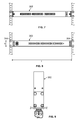
- FIG. 6 is a top view of the fan-out and parking module of FIG. 5 ;
- FIG. 7 is a rear view of the fan-out and parking module of FIG. 6 ;
- FIG. 8 is a front view of the fan-out and parking module of FIG. 6 ;
- FIG. 9 is a side view of the fan-out and parking module of FIG. 6 ;
- FIG. 10 is a cross-sectional view taken along section line 10 - 10 of FIG. 4 ;
- FIG. 11 is cross-sectional view taken along section line 11 - 11 of FIG. 4 ;
- FIGS. 12 and 13 show ruggedized multi-fiber optic connectors that can be used in systems in accordance with the principles of the present disclosure
- FIG. 14 is a perspective view of a fiber optic connector having a ferrule on which a dust cap is mounted;
- FIG. 15 is a cross-sectional view of the fiber optic connector taken along a cross-sectional plane that extends along a central longitudinal axis of the fiber optic connector and that bisects the fiber optic connector;
- FIGS. 16A and 16B show an another fan-out and parking module in accordance with the principles of the present disclosure
- FIG. 17 shows a fan-out module in accordance with the principles of the present disclosure
- FIG. 18 is another fan-out module in accordance with the principles of the present disclosure.
- FIG. 19 shows a parking module in accordance with the principles of the present disclosure
- FIG. 20 is a front perspective view of a another fan-out module in accordance with the principles of the present disclosure.
- FIG. 21 is a top view of the fan-out module of FIG. 20 .
- the telecommunications network 10 is a cellular network 10 .
- the cellular network 10 includes a cell site 12 , a demarcation point 14 (e.g., a splice vault), a backhaul 16 and a core network 18 .
- demarcation point 14 e.g., a splice vault
- backhaul 16 e.g., a core network 18 .
- the cell site 12 creates an area of telecommunications coverage (i.e., a cell) in the cellular network 10 .
- the cell site 12 includes a cell tower or mast 20 and a but 22 enclosing telecommunications equipment that is in communication with the tower 20 .
- the but 22 can enclose active equipment (e.g., multiplexing devices, de-multiplexing devices, routers, optical-to-digital converters, etc.) that connects to remote transceivers 28 (e.g., remote radio heads) mounted on the cell tower 20 .
- active equipment e.g., multiplexing devices, de-multiplexing devices, routers, optical-to-digital converters, etc.
- the remote transceivers 28 are adapted to transmit and receive signals to and from devices (e.g., mobile phones, smart-phones, devices with wireless internet connectivity, etc.) of subscribers to the cellular network 10 .
- the tower 20 may include an antenna or antennas.
- the remote transceivers 28 may be integrated into the antenna or antennas.
- the but 22 is shown housing an equipment mounting rack 200 and an equipment cabinet 202 .
- the active equipment cabinet 202 can house active equipment such as multiplexing devices, de-multiplexing devices, routers, optical-to-digital converters.
- the equipment in the cabinet 202 connects to the remote transceivers 28 .
- the equipment mounting rack 200 provides a location for mounting equipment 300 adapted to interface with cables 204 routed from the demarcation point 14 to the but 22 .
- the rack 200 can include a frame having different widths W (e.g., a “19 inch” rack typically has an 18.31 center-to-center spacing between fastener openings and a “24 inch” typically has a 22.31 inch center-to-center spacing between fastener openings).
- the frame can include spaced-apart vertical mounting rails 203 (see FIGS. 5 and 6 ) defining the fastener openings for mounting equipment to the rack.
- the cables 204 can include multi-fiber cables each including a jacket enclosing a plurality of optical fibers. In one embodiment, the cables 204 can be terminated by ruggedized multi-fiber connectors 500 a .
- the equipment 300 mounted to the rack 200 can include ruggedized multi-fiber connectors 500 b that interconnect with the ruggedized multi-fiber connectors 500 a .
- the equipment 300 can also include fan-out devices and a plurality of fiber optic cords 302 (e.g., patch cords, connectorized pigtails, etc.) that extend from the rack 200 to the cabinet 202 .
- signals are transmitted from the core network 18 through the backhaul 16 to the demarcation point 14 .
- the signals are transmitted through the cables 204 to the equipment 300 at the rack 200 .
- the fiber optic cords 302 carry the signals from the rack 200 to the equipment in the cabinet 202 .
- the signals are then directed from the equipment in the cabinet 202 to the remote transceivers 28 which transmit the signals to subscribers of the cellular network.
- the transceivers 28 are also capable of receiving signals from the subscribers.
- the received signals are directed to the equipment of the cabinet 202 .
- the fiber optic cords 302 carry the signals from the cabinet 202 to the equipment 300 at the rack 200 .
- the cables 204 then carry the signals from the rack 200 to the demarcation point 14 .
- the signals are subsequently carried through the backhaul 16 to the core network 18 .
- FIGS. 2-9 show a fan-out and parking module 300 a that is an example of the type of equipment 300 that can be mounted on the rack 200 .
- the fan-out and parking module 300 a is be configured to occupy only one rack unit of the rack 200 and has a height h less than or equal to 1.75 inches.
- the fan-out and parking module 300 a includes a module main body 302 which also can be referred to as a frame, support structure, member, or like terms.
- the module main body 302 is secured to the rack 200 by universal brackets 304 fastened to opposite ends 312 , 314 of the module main body 302 .
- Each of the universal brackets 304 includes a long leg 306 arranged perpendicularly relative to a short leg 308 .
- Fastener openings 310 are defined by the long and short legs 306 , 308 .
- the fastener openings 310 are adapted to receive fasteners for attaching the legs 306 , 308 to either the module main body 302 or the rails 203 of the rack 200 .
- the fan-out and parking module 300 a can be connected to a standard 19 inch rack by fastening the short legs 308 to the rails 203 .
- the fan-out and parking module 300 a can be attached to a standard 23 inch rack by attaching the short legs 308 to the module main body 302 and the long legs 306 to the rails 203 of the rack 200 .
- the module main body 302 includes a front panel 316 having a length L that extends between the opposite ends 312 , 314 of the module main body 302 .
- the front panel 316 has a front side 318 positioned opposite from a back side 320 .
- One or more fan-out blocks 322 are mounted to the module main body 302 at a location behind the back side 320 of the front panel 316 .
- One or more parking blocks 324 are mounted to the front side 318 of the front panel 316 .
- the parking blocks 324 can also be referred to as connector storage sub-modules.
- the fan-out blocks 322 and the parking blocks 324 are adapted to support and manage various portions of a fiber optic cable assembly 326 .
- the fiber optic cable assembly 326 includes a first end 328 having the ruggedized multi-fiber connector 500 b (e.g., a 12 fiber connector) and a second end 330 having a plurality of single fiber connectors 332 that are managed/stored at the parking blocks 324 .
- the fiber optic cable assembly 326 also includes a segment of ruggedized cable 334 that extends from the ruggedized multi-fiber connector 500 b to the fan-out block 322 .
- the fiber optic cable assembly 326 further includes a plurality (e.g., twelve) of segments of pigtail cable 336 that extend from the fan-out blocks 322 to the single fiber connectors 332 .
- the fiber optic cable assembly 326 additionally includes a plurality of separate optical fibers 511 ′ that extend continuously in an uninterrupted manner from multi-fiber connector 500 b , through the segment of ruggedized cable 334 , the fan-out block 322 and the segments of pigtail cable 336 to the single fiber connectors 332 .
- the multi-fiber connectors 500 a , 500 b are shown at FIGS. 12 and 13 .
- the connector 500 a can be sized and shaped to interface with the second connector 500 b without an intermediate fiber optic adapter.
- the first connector 500 a can define a plug and the second example connector 500 b can define a receptacle that is configured to receive the plug.
- the plug and receptacle are threaded together.
- other types of connectors e.g., non-ruggedized MPO/MFC connectors could be used).
- the connector plug 500 a includes a ferrule 510 at which one or more optical fibers 511 of the cable 204 are terminated.
- the ferrule 510 terminates multiple (e.g., two, eight, twelve, sixteen, twenty-four, forty-eight, seventy-two, etc.) optical fibers 511 .
- the ferrule 510 terminates twelve optical fibers 511 .
- the ferrule 510 defines keying openings 512 at either side of the optical fibers 511 .
- the ferrule 510 is enclosed within a shroud 514 that defines keying and latching features.
- the shroud 514 and ferrule 510 extend forwardly of a connector base 515 .
- the shroud 514 extends beyond the ferrule 510 .
- the shroud 514 defines a first keying channel 520 and a second keying channel 522 above and below the ferrule 510 , respectively.
- the connector receptacle 500 b also includes a ferrule 510 ′ at which one or more of the optical fibers 511 ′ of the fiber optic cable assembly 326 are terminated.
- the ferrule 510 ′ terminates multiple (e.g., two, eight, twelve, sixteen, twenty-four, forty-eight, seventy-two, etc.) optical fibers 511 .
- the ferrule 510 ′ terminates twelve optical fibers 511 ′.
- the ferrule 510 ′ defines keying projections 512 ′ at either side of the optical fibers 511 ′.
- the projections 512 ′ are configured to be inserted into the keying openings 512 of the plug ferrule 510 to facilitate alignment of the ferrules 510 , 510 ′.
- the receptacle ferrule 510 ′ is enclosed within a connector body 515 ′ defines a cavity 514 ′ that is sized and shaped to receive the shroud 514 of the plug 500 .
- the connector base 515 ′ is configured to surround the shroud 514 .
- the connector base 515 ′ latches, screws, or otherwise secures to the shroud 514 to retain the plug 500 and the receptacle 500 ′ in a mated configuration.
- a first keying projection 520 ′ and a second keying projection 522 ′ are positioned within the cavity 514 ′ above and below the ferrule 510 ′, respectively.
- the first and second keying projections 520 ′, 522 ′ have different shapes and/or sizes to facilitate finding the correct orientation of the plug and receptacle.
- the connectors 500 a , 500 b include an environmental seal when interfaced together to protect the ferrules 511 , 511 ′ from dust, dirt, or other contaminants.
- an environmental dust cap can be mounted to the connectors 500 a , 500 b to protect the ferrules 511 , 511 ′ prior to deployment of the connectors 500 a , 500 b .
- the connector 500 a can be mounted to the fiber optic cable assembly 326 and the connector 500 b can be mounted to the cable 204 .
- FIG. 10 is a cross-sectional view taken along a cross-section line cut through the segment of ruggedized cable 334 .
- the ruggedized cable 334 includes an outer jacket 350 having a flattened configuration.
- the profile of the outer jacket 350 (shown at FIG. 10 ) defines a major axis A 1 and a minor axis A 2 .
- the profile of the outer jacket 350 has a dimension d 1 that extends along the major axis A 1 and a dimension d 2 that extends along the minor axis A 2 .
- the dimension d 1 is larger than the dimension d 2 such that the profile is elongated along the major axis A 1 .
- the ruggedized cable 334 includes a central buffer tube 352 containing the optical fibers 511 ′.
- the ruggedized cable 334 also includes reinforcing members 354 positioned on the major axis A 1 on opposite sides of the buffer tube 352 .
- the reinforcing members 354 are reinforcing rods including fiber glass embedded in an epoxy matrix.
- First ends of the reinforcing members 354 are anchored (e.g., adhesively bonded, crimped, etc.) to the housing of the connector 500 b and opposite second ends of the reinforcing members 354 are anchored (e.g., adhesively bonded, crimped, etc.) to one of the fan-out block 322 .
- FIG. 11 is a cross-sectional view taken along a cross-section line cut through one of the segments of pigtail cable 336 .
- the pigtail cable 336 includes an outer jacket 360 having a round configuration. In one embodiment, the outer jacket 360 has an outer diameter less than or equal to 2 millimeters.
- the pigtail cable 336 also includes an optional buffer tube 362 (e.g., a loose or tight 900 micron diameter buffer tube) containing one of the optical fibers 511 ′.
- a layer of flexible strength members 364 e.g., aramid yarn is provided between the buffer tube 362 and the outer jacket 360 .
- First ends of the strength members 364 are anchored (e.g., adhesively bonded, crimped, etc.) to one of the fan-out blocks 322 and second ends of the strength members 364 are anchored (e.g., adhesively bonded, crimped, etc.) to the housing of the corresponding single fiber connector 332 .
- the fan-out blocks 322 are mounted (e.g., attached with fasteners or other means) to the module main body 302 .
- the fan-out block 322 functions to anchor the second end of the ruggedized cable 334 and the first ends of the pigtail cables 336 to the module main body 302 .
- the fan-out block 322 also functions to fan-out (e.g., guide, direct, separate, etc.) the fibers 511 ′ from the buffer tube of the ruggedized cable 334 to the individual pigtail cables 336 .
- the front panel 316 of the module main body 302 defines one or more cable pass-through openings 370 that extends through the front panel 316 in a back-to-front direction.
- One or more strain relief boots 372 are mounted to the front side 318 of the front panel 316 .
- the boots 372 project forwardly from the front side 318 of the front panel 316 and each include a passage 374 that aligns with a corresponding one of the cable pass-through openings 370 .
- the pigtail cables 336 are routed forwardly from the fan-out blocks 322 through the cable pass-through openings 370 and the boots 372 to the front of the front panel 316 .
- the pigtail cables 336 are then routed to the parking blocks 324 at the front side of the front panel 316 where the single fiber connectors 332 are held.
- Each boot 372 receives a plurality of the pigtail cables 336 and has a flexible configuration adapted for distributing side loading across an extended length to protect the fibers 511 ′ from being bent to sharply when the pigtail cables 336 are pulled downwardly, upwardly or laterally relative to the module main body 302 .
- FIGS. 14 and 15 show one of the single fiber connectors 332 which is depicted as a standard SC style connector.
- the single fiber connector 332 includes an inner housing 380 supporting a cylindrical ferrule 382 supporting the end of one of the fibers 511 ′.
- the ferrule defines an axis 384 and is movable relative the inner housing 380 along the axis 384 .
- the ferrule 382 is spring biased relative to the inner housing 380 toward an outer axial position.
- the single fiber connector 332 also includes an outer release sleeve 386 (e.g., a grip housing) that is mounted over the inner housing 380 .
- the outer release sleeve 386 is moveable relative to the inner housing 380 along the axis 384 and is pulled back relative to the inner housing 380 to release the connector 332 from a standard SC fiber optic adapter.
- a polished end face of the ferrule 382 is preferably protected by a dust cap 388 .
- the dust cap 388 is generally cylindrical and includes an open end 389 positioned opposite from a closed end 390 .
- the open end 389 fits over the ferrule 382 such that an end portion of the ferrule is received within the dust cap 388 with the polished end face opposing the closed end 390 of the dust cap 388 .
- the dust cap 388 is secured to the ferrule 382 by a friction fit with an inner surface of the dust cap 388 engaging a circumference of the ferrule 382 such that a circumferential seal is formed between the ferrule 382 and a side wall of the dust cap 388 .
- the parking blocks 324 can be secured to the front panel 316 by releasable connections that allow the parking blocks to easily be connected and disconnected from the front panel 316 while the connectors 332 are concurrently held by the connector blocks 324 .
- the parking blocks 324 can be connected to the front panel 316 by snap-fit connections.
- the parking blocks 324 can include latches and/or tabs that snap within corresponding openings defined by the front panel 316 .
- Example parking systems suitable for use in the system disclosed herein are disclosed in U.S. Pat. Nos. 7,198,409; 7,277,620; and 7,233,731, which are hereby incorporated by reference in their entireties.
- the parking blocks 324 each include a plurality of connector holders 400 each adapted for holding one of the fiber optic connectors 332 .
- the dust caps 388 remain on the ferrules 382 of the connectors 332 while the connectors are being held by the connector holders 400 .
- the connector holders 400 are not fiber optic adapters and are not capable of optically connecting two of the fiber optic connectors 332 together. As shown at FIG. 2 , the connector holders 400 hold the connectors 332 such that boots of the connectors 332 project outwardly from the front panel 316 at least partially in a forward direction. In one embodiment, the connector holders 400 hold the connectors 332 with their axes 384 horizontal and perpendicular to the front panel 316 .
- the module 300 a is mounted to the rack 200 with the connectors 332 stored in the parking blocks 324 .
- the connector 500 b is connected to the connector 500 a so that the optical fibers 511 ′ of the fiber optic cable assembly 326 are place in communication with the backhaul.
- one of the connectors 332 is removed from its corresponding parking block 324 and the corresponding segment of pigtail cable 336 is routed from the rack 200 to the cabinet 202 .
- the dust cap 388 is removed from the ferrule of the connector 332 and the connector is connected to a piece of equipment (e.g., a multiplexer) on at the cabinet 202 .
- the segments of pigtail cable 336 are long enough to be routed from the rack 200 to the cabinet 202 without needing any intermediate patch cords.
- the connector 332 corresponding to the subscriber's line can be disconnected from the equipment at the cabinet 202 .
- the dust cap 388 can be returned to the ferrule and the connector can be plugged back into one of the parking blocks 324 at the fan-out and parking module 300 a.
- FIGS. 16A and 16B shows an alternative fan-out and parking module 300 b in accordance with the principles of the present disclosure.
- the fan-out and parking module 300 b includes the fan-out blocks 322 , the parking blocks 324 and the fiber optic cable assembly 326 including the multi-fiber connector 500 b at one end and a plurality of single fiber connectors 332 at the opposite end.
- the fan-out and parking module 300 b includes a module main body 302 ′ having a U-shaped channel for receiving the fan-out blocks 322 .
- the blocks 322 are mounted in a stacked configuration on a base of the U-shaped channel.
- a front panel projects laterally outwardly from the U-shaped channel.
- the parking blocks 324 are mounted to a front side of the front panel.
- FIGS. 17-19 show another fan-out and parking system 600 in accordance with the principles of the present disclosure.
- the system 600 includes a fan-out module 602 ( FIG. 17 or 18 ) that is used in combination with a separate parking module 604 ( FIG. 19 ).
- the fan-out module 602 and the parking module 604 are both adapted for connection to a rack 200 and preferably have a height less than or equal to one rack unit.
- the fan-out module 602 includes a main module body 606 in the form of a channel member 608 having a U-shaped transverse cross-sectional shape. A width of the fan-out module is less than the width W of the rack 200 .
- the channel member 608 includes a base portion 610 and two opposing leg portions 612 .
- One of the universal brackets 304 can be selectively attached to either of the leg portions 612 depending upon which side of the rack it is desired to mount the fan-out module 602 .
- universal brackets 304 can be attached to both leg portions 612 (see FIG. 18 ).
- One of the fan-out blocks 622 is fastened to the base portion 610 thereby mechanically coupling the fiber optic cable assembly 326 to the main module body 606 .
- the fan-out module 602 can be used to mount/secure the fiber optic cable assembly 326 to the rack 200 .
- the parking module 604 includes a main module body 616 in the form of a channel member 618 having a U-shaped transverse cross-sectional shape. A width of the fan-out module is less than the width W of the rack 200 .
- the channel member 618 includes a base portion 620 and two opposing leg portions 622 .
- One of the universal brackets 304 can be selectively attached to either of the leg portions 622 depending upon which side of the rack it is desired to mount the parking module 604 . In alternative embodiments, universal brackets 304 can be attached to both leg portions 622 .
- Parking blocks 624 are detachable mounted to a front face of the base portion 620 .
- the parking module 604 can be used to store the connectors 332 of the fiber optic cable assembly 326 corresponding to the fan-out module 602 .
- FIGS. 20 and 21 show another fan-out system 700 in accordance with the principles of the present disclosure.
- the system 700 includes a fan-out module 702 that includes a main module body 706 having a tray-like configuration.
- the width of the fan-out module 702 corresponds generally to the width W of the rack 200 .
- the main module body 706 includes a bottom wall 708 .
- a front wall 710 , opposing side walls 712 , 714 and a rear wall 716 project upwardly form the bottom wall 708 and define an interior region 718 of the main module body 706 .
- the side walls 712 , 714 extend between the front and rear walls 710 , 716 .
- the side wall 712 includes a rear notch 719 forming a rear portion of the side wall 712 which has a reduced height as compared to a front portion of the side wall 712 .
- the rear wall 716 has a reduced height as compared to the front wall 710 .
- the rear portion of the side wall 712 and the rear wall 716 have the same height.
- Universal brackets 304 are attached to the side walls 712 , 714 for allowing the fan-out module 702 to be attached to a rack 200 .
- Two rows of fiber optic adapters 720 are mounted to the front wall 710 .
- the fiber optic adapters 720 include back ports facing rearwardly from a back side of the front wall 710 and front ports facing forwardly from a front side of the front wall 710 .
- the fan-out blocks 322 are fastened to the bottom wall 708 within the interior region 718 at a location adjacent the rear wall 716 .
- the fan-out blocks 322 are oriented such that the ruggedized cable segments 334 are aligned along axes 335 that pass through the notch 719 or the rear portion of the side wall 712 positioned beneath the notch 719 .
- the axes 335 are depicted as being substantially/generally parallel (i.e., parallel or almost parallel) to the rear wall 716 .
- the multi-fiber connectors 500 b are positioned within the interior region 718 with the lower connector 500 b supported on the bottom wall 708 .
- the pigtail cable segments 336 can be routed around bend radius limiters 726 or other cable management structures mounted to the bottom wall 708 .
- the connectors 332 can be inserted into the rear ports of the fiber optic adapters 720 .
- Patch cords can be plugged into the front ports of the fiber optic adapters 720 and used to connect the fiber optic cable assemblies 326 to equipment at the cabinet 202 .
- equipment mounting structure means frames, racks, cabinets or other structures to which telecommunications equipment can be mounted.
Abstract
Description
Claims (13)
Priority Applications (1)
| Application Number | Priority Date | Filing Date | Title |
|---|---|---|---|
| US13/331,591 US8873922B2 (en) | 2010-12-20 | 2011-12-20 | Fan-out and parking module |
Applications Claiming Priority (2)
| Application Number | Priority Date | Filing Date | Title |
|---|---|---|---|
| US201061425140P | 2010-12-20 | 2010-12-20 | |
| US13/331,591 US8873922B2 (en) | 2010-12-20 | 2011-12-20 | Fan-out and parking module |
Publications (2)
| Publication Number | Publication Date |
|---|---|
| US20120189260A1 US20120189260A1 (en) | 2012-07-26 |
| US8873922B2 true US8873922B2 (en) | 2014-10-28 |
Family
ID=46544227
Family Applications (1)
| Application Number | Title | Priority Date | Filing Date |
|---|---|---|---|
| US13/331,591 Active 2033-04-29 US8873922B2 (en) | 2010-12-20 | 2011-12-20 | Fan-out and parking module |
Country Status (1)
| Country | Link |
|---|---|
| US (1) | US8873922B2 (en) |
Cited By (2)
| Publication number | Priority date | Publication date | Assignee | Title |
|---|---|---|---|---|
| US10725252B1 (en) | 2019-07-03 | 2020-07-28 | Hewlett Packard Enterprise Development Lp | Modular optical ferrule adapter and carrier systems for customizable optical connectivity and having moveable ferrule carriers |
| US11686911B2 (en) | 2020-09-17 | 2023-06-27 | Panduit Corp. | Optical distribution and splice frame including enclosures |
Families Citing this family (62)
| Publication number | Priority date | Publication date | Assignee | Title |
|---|---|---|---|---|
| US8961035B2 (en) | 2010-08-02 | 2015-02-24 | Adc Telecommunications, Inc. | Architecture for a fiber optic network |
| US9188747B2 (en) | 2011-05-23 | 2015-11-17 | Senko Advanced Components, Inc. | True one piece housing fiber optic adapter |
| US8974124B2 (en) | 2012-08-16 | 2015-03-10 | Senko Advanced Components, Inc. | Fiber optic connector |
| US9268103B2 (en) | 2013-05-10 | 2016-02-23 | Senko Advanced Components, Inc. | Interlockable fiber optic connector adaptors |
| US9360649B2 (en) | 2013-05-22 | 2016-06-07 | Senko Advanced Components, Inc. | Cable guide for fiber optic cables |
| US9618703B2 (en) | 2013-10-03 | 2017-04-11 | Senko Advanced Components, Inc. | Connector housing for securing an optical cable and methods of use and manufacture thereof |
| US9477049B2 (en) | 2013-12-20 | 2016-10-25 | Senko Advanced Components, Inc. | Lockable connectors and connection assemblies |
| US9535230B2 (en) | 2014-01-31 | 2017-01-03 | Senko Advanced Components, Inc. | Integrated fiber optic cable fan-out connector |
| US9297964B2 (en) | 2014-04-18 | 2016-03-29 | Senko Advanced Components, Inc. | Optical fiber connector assembly |
| US9274287B2 (en) | 2014-05-13 | 2016-03-01 | Senko Advanced Components, Inc. | Optical fiber connector and ferrule |
| US9618702B2 (en) | 2014-06-09 | 2017-04-11 | Senko Advanced Components, Inc. | Reduced-profile data transmission element connectors, adapters, and connection assemblies thereof |
| US9599778B2 (en) | 2014-10-22 | 2017-03-21 | Senko Advanced Components, Inc. | Latching connector with remote release |
| US9494745B2 (en) | 2015-01-16 | 2016-11-15 | Senko Advanced Components, Inc. | Sealable communication cable connection assemblies |
| US9658409B2 (en) | 2015-03-03 | 2017-05-23 | Senko Advanced Components, Inc. | Optical fiber connector with changeable polarity |
| US9684139B2 (en) | 2015-05-29 | 2017-06-20 | Senko Advanced Components, Inc. | Optical fiber connector with changeable gender |
| WO2017081306A1 (en) * | 2015-11-13 | 2017-05-18 | CommScope Connectivity Belgium BVBA | Fiber optic connection system |
| US9726830B1 (en) | 2016-06-28 | 2017-08-08 | Senko Advanced Components, Inc. | Connector and adapter system for two-fiber mechanical transfer type ferrule |
| EP3503764B1 (en) * | 2016-08-26 | 2023-06-07 | NLIGHT, Inc. | Laser module service shelf |
| EP3535614A1 (en) * | 2016-11-07 | 2019-09-11 | Corning Research & Development Corporation | Optical fiber connector with integrated installation tools |
| US10228521B2 (en) | 2016-12-05 | 2019-03-12 | Senko Advanced Components, Inc. | Narrow width adapters and connectors with modular latching arm |
| US10078188B1 (en) | 2016-12-05 | 2018-09-18 | Senko Advanced Components, Inc. | Springless push/pull fiber optic connector |
| JP6298547B1 (en) * | 2017-01-10 | 2018-03-20 | 株式会社フジクラ | Wire-shaping member and optical wiring unit |
| US10444444B2 (en) | 2017-01-30 | 2019-10-15 | Senko Advanced Components, Inc. | Remote release tab connector assembly |
| US11333836B2 (en) | 2017-01-30 | 2022-05-17 | Senko Advanced Components, Inc. | Adapter for optical connectors |
| US10416394B2 (en) | 2017-01-30 | 2019-09-17 | Senko Advanced Components, Inc. | Fiber optic receptacle with integrated device therein |
| CN110249248B (en) | 2017-01-30 | 2021-07-27 | 扇港元器件股份有限公司 | Optical connector with reversible polarity |
| US10185100B2 (en) | 2017-01-30 | 2019-01-22 | Senko Advanced Components, Inc | Modular connector and adapter assembly using a removable anchor device |
| US10725248B2 (en) | 2017-01-30 | 2020-07-28 | Senko Advanced Components, Inc. | Fiber optic receptacle with integrated device therein incorporating a behind-the-wall fiber optic receptacle |
| US10209461B2 (en) | 2017-04-07 | 2019-02-19 | Senko Advanced Components | Behind the wall optical connector with reduced components |
| US10359583B2 (en) | 2017-04-07 | 2019-07-23 | Senko Advanced Components, Inc. | Behind the wall optical connector with reduced components |
| US10754098B2 (en) | 2017-04-07 | 2020-08-25 | Senko Advanced Components, Inc. | Behind the wall optical connector with reduced components |
| US10989884B2 (en) | 2017-04-07 | 2021-04-27 | Senko Advanced Components, Inc. | Behind the wall optical connector with reduced components |
| US10718910B2 (en) | 2017-05-03 | 2020-07-21 | Senko Advanced Components, Inc | Field terminated ruggedized fiber optic connector system |
| US10146016B1 (en) | 2017-05-10 | 2018-12-04 | Senko Advanced Components, Inc | MPO micro-latchlock connector |
| US10401576B2 (en) | 2017-05-10 | 2019-09-03 | Senko Advanced Components, Inc. | MPO micro-latch-lock connector |
| US10520686B2 (en) | 2017-05-18 | 2019-12-31 | Senko Advanced Components, Inc. | Optical connector with one-piece body |
| US10359576B2 (en) | 2017-06-15 | 2019-07-23 | Senko Advanced Components, Inc. | SC low profile connector with optional boot |
| US10281669B2 (en) | 2017-07-14 | 2019-05-07 | Senko Advance Components, Inc. | Ultra-small form factor optical connectors |
| US10718911B2 (en) | 2017-08-24 | 2020-07-21 | Senko Advanced Components, Inc. | Ultra-small form factor optical connectors using a push-pull boot receptacle release |
| US11822133B2 (en) | 2017-07-14 | 2023-11-21 | Senko Advanced Components, Inc. | Ultra-small form factor optical connector and adapter |
| US10641972B2 (en) | 2017-08-17 | 2020-05-05 | Senko Advanced Components, Inc | Anti-jam alignment sleeve holder or connector housing for a ferrule assembly |
| CN107632357B (en) * | 2017-10-19 | 2019-08-02 | 东莞中子科学中心 | A kind of multimode fibre signal is fanned out to mechanism |
| US10444442B2 (en) | 2017-11-03 | 2019-10-15 | Senko Advanced Components, Inc. | MPO optical fiber connector |
| US11002923B2 (en) | 2017-11-21 | 2021-05-11 | Senko Advanced Components, Inc. | Fiber optic connector with cable boot release having a two-piece clip assembly |
| US11112566B2 (en) | 2018-03-19 | 2021-09-07 | Senko Advanced Components, Inc. | Removal tool for removing a plural of micro optical connectors from an adapter interface |
| CN111033339B (en) | 2018-03-28 | 2023-09-19 | 扇港元器件股份有限公司 | Optical fiber connector |
| US11041993B2 (en) | 2018-04-19 | 2021-06-22 | Senko Advanced Components, Inc. | Fiber optic adapter with removable insert for polarity change and removal tool for the same |
| US10921528B2 (en) | 2018-06-07 | 2021-02-16 | Senko Advanced Components, Inc. | Dual spring multi-fiber optic connector |
| CN112088327A (en) | 2018-07-15 | 2020-12-15 | 扇港元器件股份有限公司 | Ultra-small optical connector and adapter |
| US10444441B1 (en) | 2018-08-10 | 2019-10-15 | Senko Advanced Components, Inc. | Pivotable housing for a fiber optic connector |
| US11073664B2 (en) | 2018-08-13 | 2021-07-27 | Senko Advanced Components, Inc. | Cable boot assembly for releasing fiber optic connector from a receptacle |
| US10921530B2 (en) | 2018-09-12 | 2021-02-16 | Senko Advanced Components, Inc. | LC type connector with push/pull assembly for releasing connector from a receptacle using a cable boot |
| CN112955797B (en) | 2018-09-12 | 2022-11-11 | 扇港元器件股份有限公司 | LC-type connector with clip-on push/pull tab for releasing the connector from a receptacle with a cable boot |
| US10921531B2 (en) | 2018-09-12 | 2021-02-16 | Senko Advanced Components, Inc. | LC type connector with push/pull assembly for releasing connector from a receptacle using a cable boot |
| US11806831B2 (en) | 2018-11-21 | 2023-11-07 | Senko Advanced Components, Inc. | Fixture and method for polishing fiber optic connector ferrules |
| US11175464B2 (en) | 2018-11-25 | 2021-11-16 | Senko Advanced Components, Inc. | Open ended spring body for use in an optical fiber connector |
| WO2020198755A1 (en) | 2019-03-28 | 2020-10-01 | Senko Advanced Components, Inc | Fiber optic adapter assembly |
| US11340406B2 (en) | 2019-04-19 | 2022-05-24 | Senko Advanced Components, Inc. | Small form factor fiber optic connector with resilient latching mechanism for securing within a hook-less receptacle |
| WO2020252355A1 (en) | 2019-06-13 | 2020-12-17 | Senko Advanced Components, Inc | Lever actuated latch arm for releasing a fiber optic connector from a receptacle port and method of use |
| US11467354B2 (en) | 2019-07-23 | 2022-10-11 | Senko Advanced Components, Inc. | Ultra-small form factor receptacle for receiving a fiber optic connector opposing a ferrule assembly |
| US11353664B1 (en) | 2019-08-21 | 2022-06-07 | Senko Advanced Components, Inc. | Fiber optic connector |
| US11520111B2 (en) | 2019-11-13 | 2022-12-06 | Senko Advanced Components, Inc. | Fiber optic connector |
Citations (13)
| Publication number | Priority date | Publication date | Assignee | Title |
|---|---|---|---|---|
| US7198409B2 (en) | 2003-06-30 | 2007-04-03 | Adc Telecommunications, Inc. | Fiber optic connector holder and method |
| US7233731B2 (en) | 2003-07-02 | 2007-06-19 | Adc Telecommunications, Inc. | Telecommunications connection cabinet |
| US7264402B2 (en) | 2005-03-10 | 2007-09-04 | Corning Cable Systems Llc | Multi-fiber optic receptacle and plug assembly |
| US7277620B2 (en) | 2004-06-18 | 2007-10-02 | Adc Telecommunications, Inc. | Fiber optic splitter |
| US7369741B2 (en) * | 2003-11-17 | 2008-05-06 | Fiber Optics Network Solutions Corp. | Storage adapter with dust cap posts |
| US7397997B2 (en) | 2004-03-08 | 2008-07-08 | Adc Telecommunications, Inc. | Fiber access terminal |
| US7509016B2 (en) | 2007-03-09 | 2009-03-24 | Adc Telecommunications, Inc. | Telecommunication rack unit tray |
| US7512304B2 (en) | 2007-03-23 | 2009-03-31 | Adc Telecommunications, Inc. | Drop terminal with anchor block for retaining a stub cable |
| US7715679B2 (en) | 2007-05-07 | 2010-05-11 | Adc Telecommunications, Inc. | Fiber optic enclosure with external cable spool |
| US7756379B2 (en) | 2007-08-06 | 2010-07-13 | Adc Telecommunications, Inc. | Fiber optic enclosure with internal cable spool |
| US20110222829A1 (en) | 2010-03-11 | 2011-09-15 | Todd Loeffelholz | Fiber optic enclosure with internal cable spool assembly |
| US20130177284A1 (en) * | 2011-11-14 | 2013-07-11 | Scott C. Sievers | Cable Pulling Arrangement |
| US8649649B2 (en) * | 2010-03-03 | 2014-02-11 | Adc Telecommunications, Inc. | Fiber distribution hub with connectorized stub cables |
-
2011
- 2011-12-20 US US13/331,591 patent/US8873922B2/en active Active
Patent Citations (14)
| Publication number | Priority date | Publication date | Assignee | Title |
|---|---|---|---|---|
| US7198409B2 (en) | 2003-06-30 | 2007-04-03 | Adc Telecommunications, Inc. | Fiber optic connector holder and method |
| US7233731B2 (en) | 2003-07-02 | 2007-06-19 | Adc Telecommunications, Inc. | Telecommunications connection cabinet |
| US7369741B2 (en) * | 2003-11-17 | 2008-05-06 | Fiber Optics Network Solutions Corp. | Storage adapter with dust cap posts |
| US7397997B2 (en) | 2004-03-08 | 2008-07-08 | Adc Telecommunications, Inc. | Fiber access terminal |
| US8538228B2 (en) * | 2004-06-18 | 2013-09-17 | Adc Telecommunications, Inc. | Telecommunications cabinet with connector storage |
| US7277620B2 (en) | 2004-06-18 | 2007-10-02 | Adc Telecommunications, Inc. | Fiber optic splitter |
| US7264402B2 (en) | 2005-03-10 | 2007-09-04 | Corning Cable Systems Llc | Multi-fiber optic receptacle and plug assembly |
| US7509016B2 (en) | 2007-03-09 | 2009-03-24 | Adc Telecommunications, Inc. | Telecommunication rack unit tray |
| US7512304B2 (en) | 2007-03-23 | 2009-03-31 | Adc Telecommunications, Inc. | Drop terminal with anchor block for retaining a stub cable |
| US7715679B2 (en) | 2007-05-07 | 2010-05-11 | Adc Telecommunications, Inc. | Fiber optic enclosure with external cable spool |
| US7756379B2 (en) | 2007-08-06 | 2010-07-13 | Adc Telecommunications, Inc. | Fiber optic enclosure with internal cable spool |
| US8649649B2 (en) * | 2010-03-03 | 2014-02-11 | Adc Telecommunications, Inc. | Fiber distribution hub with connectorized stub cables |
| US20110222829A1 (en) | 2010-03-11 | 2011-09-15 | Todd Loeffelholz | Fiber optic enclosure with internal cable spool assembly |
| US20130177284A1 (en) * | 2011-11-14 | 2013-07-11 | Scott C. Sievers | Cable Pulling Arrangement |
Cited By (4)
| Publication number | Priority date | Publication date | Assignee | Title |
|---|---|---|---|---|
| US10725252B1 (en) | 2019-07-03 | 2020-07-28 | Hewlett Packard Enterprise Development Lp | Modular optical ferrule adapter and carrier systems for customizable optical connectivity and having moveable ferrule carriers |
| US11686911B2 (en) | 2020-09-17 | 2023-06-27 | Panduit Corp. | Optical distribution and splice frame including enclosures |
| US11921339B2 (en) | 2020-09-17 | 2024-03-05 | Panduit Corp. | Optical distribution and splice frame including vertical cable managers |
| US11947178B2 (en) | 2020-09-17 | 2024-04-02 | Panduit Corp. | Optical distribution and splice frame including cassettes |
Also Published As
| Publication number | Publication date |
|---|---|
| US20120189260A1 (en) | 2012-07-26 |
Similar Documents
| Publication | Publication Date | Title |
|---|---|---|
| US8873922B2 (en) | Fan-out and parking module | |
| US10274686B2 (en) | Telecommunications cabinet with connector storage | |
| US10101543B2 (en) | Indexing terminals for supporting a bidirectional indexing architecture | |
| US10712516B2 (en) | Optical connection terminals for fiber optic communications networks | |
| US7869681B2 (en) | Optical connection closure having at least one connector port for optically connecting a drop cable to a distribution cable | |
| US8606067B2 (en) | Pedestal terminal with swing frame | |
| US20100278499A1 (en) | Fiber Optic Panels Configured to Retain Fiber Optic Components in a Depth Space of a Chassis | |
| US20140233903A1 (en) | Strain relief for pigtail module | |
| US20110129186A1 (en) | Fiber Optic Module Assembly and Associated Methods | |
| US8649649B2 (en) | Fiber distribution hub with connectorized stub cables | |
| US8891927B2 (en) | Fiber distribution hub with pass-through interfaces | |
| EP3673308B1 (en) | Drop terminal | |
| US20090310929A1 (en) | Optical fiber interconnection apparatus | |
| US20140133822A1 (en) | Rotatable furcation assembly | |
| US20190353854A1 (en) | Sealed connection terminal | |
| WO2020061144A1 (en) | Fiber optic closures and support structures and assemblies for fiber optic closures | |
| US11874517B2 (en) | Telecommunications terminal with stub cable | |
| US20220057589A1 (en) | Common Module Storage within a Fiber Distribution Hub | |
| WO2023164254A1 (en) | Consolidation terminals |
Legal Events
| Date | Code | Title | Description |
|---|---|---|---|
| AS | Assignment |
Owner name: ADC TELECOMMUNICATIONS, INC., MINNESOTA Free format text: ASSIGNMENT OF ASSIGNORS INTEREST;ASSIGNORS:KOWALCZYK, SCOTT C.;SIMER, JOSHUA M.;WHITAKER, JERAD D.;AND OTHERS;SIGNING DATES FROM 20120313 TO 20120403;REEL/FRAME:028276/0301 |
|
| STCF | Information on status: patent grant |
Free format text: PATENTED CASE |
|
| AS | Assignment |
Owner name: TYCO ELECTRONICS SERVICES GMBH, SWITZERLAND Free format text: ASSIGNMENT OF ASSIGNORS INTEREST;ASSIGNORS:ADC TELECOMMUNICATIONS, INC.;TE CONNECTIVITY SOLUTIONS GMBH;REEL/FRAME:036908/0443 Effective date: 20150825 |
|
| AS | Assignment |
Owner name: COMMSCOPE EMEA LIMITED, IRELAND Free format text: ASSIGNMENT OF ASSIGNORS INTEREST;ASSIGNOR:TYCO ELECTRONICS SERVICES GMBH;REEL/FRAME:036956/0001 Effective date: 20150828 |
|
| AS | Assignment |
Owner name: COMMSCOPE TECHNOLOGIES LLC, NORTH CAROLINA Free format text: ASSIGNMENT OF ASSIGNORS INTEREST;ASSIGNOR:COMMSCOPE EMEA LIMITED;REEL/FRAME:037012/0001 Effective date: 20150828 |
|
| AS | Assignment |
Owner name: JPMORGAN CHASE BANK, N.A., AS COLLATERAL AGENT, ILLINOIS Free format text: PATENT SECURITY AGREEMENT (TERM);ASSIGNOR:COMMSCOPE TECHNOLOGIES LLC;REEL/FRAME:037513/0709 Effective date: 20151220 Owner name: JPMORGAN CHASE BANK, N.A., AS COLLATERAL AGENT, ILLINOIS Free format text: PATENT SECURITY AGREEMENT (ABL);ASSIGNOR:COMMSCOPE TECHNOLOGIES LLC;REEL/FRAME:037514/0196 Effective date: 20151220 Owner name: JPMORGAN CHASE BANK, N.A., AS COLLATERAL AGENT, IL Free format text: PATENT SECURITY AGREEMENT (ABL);ASSIGNOR:COMMSCOPE TECHNOLOGIES LLC;REEL/FRAME:037514/0196 Effective date: 20151220 Owner name: JPMORGAN CHASE BANK, N.A., AS COLLATERAL AGENT, IL Free format text: PATENT SECURITY AGREEMENT (TERM);ASSIGNOR:COMMSCOPE TECHNOLOGIES LLC;REEL/FRAME:037513/0709 Effective date: 20151220 |
|
| CC | Certificate of correction | ||
| MAFP | Maintenance fee payment |
Free format text: PAYMENT OF MAINTENANCE FEE, 4TH YEAR, LARGE ENTITY (ORIGINAL EVENT CODE: M1551) Year of fee payment: 4 |
|
| AS | Assignment |
Owner name: ANDREW LLC, NORTH CAROLINA Free format text: RELEASE BY SECURED PARTY;ASSIGNOR:JPMORGAN CHASE BANK, N.A.;REEL/FRAME:048840/0001 Effective date: 20190404 Owner name: ALLEN TELECOM LLC, ILLINOIS Free format text: RELEASE BY SECURED PARTY;ASSIGNOR:JPMORGAN CHASE BANK, N.A.;REEL/FRAME:048840/0001 Effective date: 20190404 Owner name: REDWOOD SYSTEMS, INC., NORTH CAROLINA Free format text: RELEASE BY SECURED PARTY;ASSIGNOR:JPMORGAN CHASE BANK, N.A.;REEL/FRAME:048840/0001 Effective date: 20190404 Owner name: COMMSCOPE, INC. OF NORTH CAROLINA, NORTH CAROLINA Free format text: RELEASE BY SECURED PARTY;ASSIGNOR:JPMORGAN CHASE BANK, N.A.;REEL/FRAME:048840/0001 Effective date: 20190404 Owner name: COMMSCOPE TECHNOLOGIES LLC, NORTH CAROLINA Free format text: RELEASE BY SECURED PARTY;ASSIGNOR:JPMORGAN CHASE BANK, N.A.;REEL/FRAME:048840/0001 Effective date: 20190404 Owner name: REDWOOD SYSTEMS, INC., NORTH CAROLINA Free format text: RELEASE BY SECURED PARTY;ASSIGNOR:JPMORGAN CHASE BANK, N.A.;REEL/FRAME:049260/0001 Effective date: 20190404 Owner name: COMMSCOPE TECHNOLOGIES LLC, NORTH CAROLINA Free format text: RELEASE BY SECURED PARTY;ASSIGNOR:JPMORGAN CHASE BANK, N.A.;REEL/FRAME:049260/0001 Effective date: 20190404 Owner name: COMMSCOPE, INC. OF NORTH CAROLINA, NORTH CAROLINA Free format text: RELEASE BY SECURED PARTY;ASSIGNOR:JPMORGAN CHASE BANK, N.A.;REEL/FRAME:049260/0001 Effective date: 20190404 Owner name: ALLEN TELECOM LLC, ILLINOIS Free format text: RELEASE BY SECURED PARTY;ASSIGNOR:JPMORGAN CHASE BANK, N.A.;REEL/FRAME:049260/0001 Effective date: 20190404 Owner name: ANDREW LLC, NORTH CAROLINA Free format text: RELEASE BY SECURED PARTY;ASSIGNOR:JPMORGAN CHASE BANK, N.A.;REEL/FRAME:049260/0001 Effective date: 20190404 |
|
| AS | Assignment |
Owner name: WILMINGTON TRUST, NATIONAL ASSOCIATION, AS COLLATE Free format text: PATENT SECURITY AGREEMENT;ASSIGNOR:COMMSCOPE TECHNOLOGIES LLC;REEL/FRAME:049892/0051 Effective date: 20190404 Owner name: JPMORGAN CHASE BANK, N.A., NEW YORK Free format text: ABL SECURITY AGREEMENT;ASSIGNORS:COMMSCOPE, INC. OF NORTH CAROLINA;COMMSCOPE TECHNOLOGIES LLC;ARRIS ENTERPRISES LLC;AND OTHERS;REEL/FRAME:049892/0396 Effective date: 20190404 Owner name: JPMORGAN CHASE BANK, N.A., NEW YORK Free format text: TERM LOAN SECURITY AGREEMENT;ASSIGNORS:COMMSCOPE, INC. OF NORTH CAROLINA;COMMSCOPE TECHNOLOGIES LLC;ARRIS ENTERPRISES LLC;AND OTHERS;REEL/FRAME:049905/0504 Effective date: 20190404 Owner name: WILMINGTON TRUST, NATIONAL ASSOCIATION, AS COLLATERAL AGENT, CONNECTICUT Free format text: PATENT SECURITY AGREEMENT;ASSIGNOR:COMMSCOPE TECHNOLOGIES LLC;REEL/FRAME:049892/0051 Effective date: 20190404 |
|
| AS | Assignment |
Owner name: WILMINGTON TRUST, DELAWARE Free format text: SECURITY INTEREST;ASSIGNORS:ARRIS SOLUTIONS, INC.;ARRIS ENTERPRISES LLC;COMMSCOPE TECHNOLOGIES LLC;AND OTHERS;REEL/FRAME:060752/0001 Effective date: 20211115 |
|
| MAFP | Maintenance fee payment |
Free format text: PAYMENT OF MAINTENANCE FEE, 8TH YEAR, LARGE ENTITY (ORIGINAL EVENT CODE: M1552); ENTITY STATUS OF PATENT OWNER: LARGE ENTITY Year of fee payment: 8 |