US8869877B2 - Monolithic cold plate configuration - Google Patents
Monolithic cold plate configuration Download PDFInfo
- Publication number
- US8869877B2 US8869877B2 US12/901,602 US90160210A US8869877B2 US 8869877 B2 US8869877 B2 US 8869877B2 US 90160210 A US90160210 A US 90160210A US 8869877 B2 US8869877 B2 US 8869877B2
- Authority
- US
- United States
- Prior art keywords
- trough
- cold plate
- plate assembly
- drilled passage
- gun drilled
- Prior art date
- Legal status (The legal status is an assumption and is not a legal conclusion. Google has not performed a legal analysis and makes no representation as to the accuracy of the status listed.)
- Active, expires
Links
Images


Classifications
-
- F—MECHANICAL ENGINEERING; LIGHTING; HEATING; WEAPONS; BLASTING
- F28—HEAT EXCHANGE IN GENERAL
- F28F—DETAILS OF HEAT-EXCHANGE AND HEAT-TRANSFER APPARATUS, OF GENERAL APPLICATION
- F28F3/00—Plate-like or laminated elements; Assemblies of plate-like or laminated elements
- F28F3/12—Elements constructed in the shape of a hollow panel, e.g. with channels
-
- F—MECHANICAL ENGINEERING; LIGHTING; HEATING; WEAPONS; BLASTING
- F28—HEAT EXCHANGE IN GENERAL
- F28F—DETAILS OF HEAT-EXCHANGE AND HEAT-TRANSFER APPARATUS, OF GENERAL APPLICATION
- F28F9/00—Casings; Header boxes; Auxiliary supports for elements; Auxiliary members within casings
- F28F9/02—Header boxes; End plates
- F28F9/026—Header boxes; End plates with static flow control means, e.g. with means for uniformly distributing heat exchange media into conduits
-
- H—ELECTRICITY
- H01—ELECTRIC ELEMENTS
- H01L—SEMICONDUCTOR DEVICES NOT COVERED BY CLASS H10
- H01L23/00—Details of semiconductor or other solid state devices
- H01L23/34—Arrangements for cooling, heating, ventilating or temperature compensation ; Temperature sensing arrangements
- H01L23/46—Arrangements for cooling, heating, ventilating or temperature compensation ; Temperature sensing arrangements involving the transfer of heat by flowing fluids
- H01L23/473—Arrangements for cooling, heating, ventilating or temperature compensation ; Temperature sensing arrangements involving the transfer of heat by flowing fluids by flowing liquids
-
- H—ELECTRICITY
- H01—ELECTRIC ELEMENTS
- H01L—SEMICONDUCTOR DEVICES NOT COVERED BY CLASS H10
- H01L2924/00—Indexing scheme for arrangements or methods for connecting or disconnecting semiconductor or solid-state bodies as covered by H01L24/00
- H01L2924/0001—Technical content checked by a classifier
- H01L2924/0002—Not covered by any one of groups H01L24/00, H01L24/00 and H01L2224/00
-
- Y—GENERAL TAGGING OF NEW TECHNOLOGICAL DEVELOPMENTS; GENERAL TAGGING OF CROSS-SECTIONAL TECHNOLOGIES SPANNING OVER SEVERAL SECTIONS OF THE IPC; TECHNICAL SUBJECTS COVERED BY FORMER USPC CROSS-REFERENCE ART COLLECTIONS [XRACs] AND DIGESTS
- Y10—TECHNICAL SUBJECTS COVERED BY FORMER USPC
- Y10T—TECHNICAL SUBJECTS COVERED BY FORMER US CLASSIFICATION
- Y10T29/00—Metal working
- Y10T29/49—Method of mechanical manufacture
- Y10T29/4935—Heat exchanger or boiler making
Definitions
- the present disclosure relates to a heat transfer device, and more particularly to a cold plate assembly.
- Heat removal provides, for example, lower operating temperatures, higher operating speeds, greater computing power and higher reliability.
- Cold plates are liquid cooled structures with numerous closely spaced fluid passages which provide a heat transfer function for components mounted thereto.
- the fluid passages may be gun drilled from opposite ends.
- a cold plate assembly includes a monolithic cold plate which defines a trough located to intersect a fluid path.
- a cold plate assembly includes a monolithic cold plate which defines a trough located to intersect a fluid path that includes a multiple of parallel passages, each of the parallel passages defined by a first gun drilled passage and a second gun drilled passage which intersect the trough, the trough defines a generally toothed configuration with a multiple of open areas, each of the multiple of open areas corresponds with one of the multiple of parallel passages to separate the respective first gun drilled passage and the second gun drilled passage.
- a cap receivable within the trough, the cap defines a multiple of cap teeth which fit within the respective multiple of open areas, each of the multiple of cap teeth defines an orifice which provides fluid communication between the respective first gun drilled passage and the second gun drilled passage.
- a method of manufacturing a cold plate according to an exemplary aspect of the present disclosure includes gun drilling a first passage from one side of a monolithic plate into a trough and gun drilling a second passage opposed to the first passage from an opposite side of the monolithic plate into the trough.
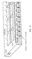
- FIG. 1A is a general perspective phantom view of a cold plate assembly
- FIG. 1B is a general top phantom view of the cold plate assembly
- FIG. 2 is a sectional view along line 2 - 2 in FIG. 1A through a fluid manifold of the cold plate assembly;
- FIG. 3 is a sectional view along line 3 - 3 in FIG. 1A to illustrate a first and second fluid path, each with numerous parallel oriented individual fluid passages within the cold plate assembly;
- FIG. 4 is a general perspective bottom view of the cold plate assembly
- FIG. 5 is an exploded view of the cold plate assembly
- FIG. 6 is an expanded bottom view of the cold plate assembly illustrating a trough which intersects the fluid paths
- FIG. 7 is a sectional view along line 7 - 7 in FIG. 6 to illustrate the troughs
- FIG. 8 is an expanded sectional view along line 8 - 8 in FIG. 6 to illustrate an open area formed by the trough which intersects an individual fluid passage;
- FIG. 10 is an expanded sectional view along line 10 - 10 in FIG. 4 to illustrate the open area formed by the trough which intersects an individual fluid passage and a cap tooth which defines an orifice therein;
- FIG. 11 is a perspective view of a cap which closes the trough of the cold plate assembly.
- FIG. 12 is an expanded sectional view along line 12 - 12 in FIG. 4 to illustrate the cap which closes the trough and the location of the orifices within the individual gun drilled fluid passages.
- FIG. 1A schematically illustrates a cold plate assembly 20 .
- the cold plate assembly 20 as disclosed herein is a redundant fluid monolithic cold plate assembly which provides structural rigidity and may be manufactured of, for example, an aluminum alloy. It should be understood that other structures with gun drilled passages may additionally benefit herefrom.
- the cold plate assembly 20 generally includes a plate 22 with a first inlet port 24 - 1 and a second inlet port 24 - 2 that communicates fluid into a respective first inlet fluid manifold 26 - 1 and second inlet fluid manifold 26 - 2 . Fluid is communicated through the respective inlet fluid manifolds 26 - 1 , 26 - 2 then into a respective first fluid path 28 - 1 and second fluid path 28 - 2 which extend transverse to the inlet fluid manifolds 26 - 1 , 26 - 2 and across the plate 22 .
- the fluid is collected in outlet fluid manifolds 30 - 1 , 30 - 2 for communication out of the cold plate assembly 20 through a respect first outlet port 32 - 1 and second outlet port 32 - 2 to thereby provide fluid circulation therethrough.
- the inlet fluid manifolds 26 - 1 , 26 - 2 , outlet fluid manifolds 30 - 1 , 30 - 2 and the fluid paths 28 - 1 , 28 - 2 are machined in the plate 22 then closed with various plugs (not specifically shown).
- the inlet fluid manifolds 26 - 1 , 26 - 2 and outlet fluid manifolds 30 - 1 , 30 - 2 are generally transverse to the first fluid path 28 - 1 and second fluid path 28 - 2 which extend therebetween.
- the inlet fluid manifold 26 - 1 communicates with the outlet fluid manifold 30 - 1 through the first fluid path 28 - 1 and the inlet fluid manifold 26 - 2 communicates with the outlet fluid manifold 30 - 2 through the second fluid path 28 - 2 .
- the first fluid path 28 - 1 and second fluid path 28 - 2 each respectively include numerous parallel oriented individual fluid passages 28 - 1 a - n and 28 - 2 a - n .
- the fluid passages 28 - 1 a - n typically alternate with the second fluid passages 28 - 2 a - n and communicate with their respective inlet fluid manifolds 26 - 1 , 26 - 2 and outlet fluid manifolds 30 - 1 , 30 - 2 through respective transverse passages 27 - 1 a - n , 27 - 2 a - n and 29 - 1 a - n , 29 - 2 a - n ( FIG. 1B ).
- each passage 28 - 1 a - n and 28 - 2 a - n are individually gun drilled from opposite sides 22 A, 22 B of the plate 22 by gun drilled passages P 1 , P 2 which meet generally at an intersection 22 M of the plate 22 ( FIGS. 3 and 4 ). It should be understood that the intersection 22 M is generally located at the middle section of the plate 22 to minimize each gun drill passage P 1 , P 2 length; however, other design considerations may result in locating the intersection 22 M at other positions within the plate 22 .
- a trough 34 - 1 , 34 - 2 is located at the intersection 22 M. That is, trough 34 - 1 is located at the gun drill intersection which defines each passage 28 - 1 a - n of the first fluid path 28 - 1 and trough 34 - 2 is located at the gun drill intersection which defines each passage 28 - 2 a - n of the second fluid path 28 - 2 .
- Each trough 34 - 1 , 34 - 2 is of a generally toothed configuration.
- the first trough 34 - 1 defines an open area 36 - 1 between each trough tooth 38 - 1 at the gun drill intersection of the gun drilled passages P 1 , P 2 for each individual fluid passages 28 - 1 a - n of the first fluid path 28 - 1 while the trough teeth 38 - 1 allow passage of the individual fluid passages 28 - 2 a - n of the second fluid path 28 - 2 to the second trough 34 - 2 ( FIG. 6 ).
- the second trough 34 - 2 defines an open area 36 - 2 between each trough tooth 38 - 2 at the gun drill intersection of the gun drilled passages P 1 , P 2 for each individual fluid passages 28 - 2 a - n of the second fluid path 28 - 2 while the trough teeth 38 - 2 allow passage of the individual fluid passages 28 - 1 a - n of the first fluid path 28 - 1 to the first trough 34 - 2 ( FIG. 7 ). That is, the teeth 38 - 1 , 38 - 2 are offset and in alignment with the opposite respective fluid passages 28 - 1 a - n and 28 - 2 a - n .
- the troughs 34 - 1 , 34 - 2 thereby remove the location at which the two gun drilled passages P 1 , P 2 intersect and thereby eliminate any potential mismatch ( FIG. 8 ). Also, direct access is provided to each individual fluid passages 28 - 1 a - n and 28 - 2 a - n for direct inspection of any drill wander ( FIG. 9 ).
- a cap 40 - 1 , 40 - 2 is respectively used to close the troughs 34 - 1 , 34 - 2 .
- the cap 40 - 1 , 40 - 2 may be brazed or otherwise welded into position as typical with the multiple of plugs used to close other passages within the monolithic plate 22 .
- each cap 40 - 1 , 40 - 2 includes a multiple of cap teeth 42 - 1 , 42 - 2 ( FIG. 11 ) which are each received within the respective open area 36 - 1 , 36 - 2 of the troughs 34 - 1 , 34 - 2 .
- Each of the cap teeth 42 - 1 , 42 - 2 define a respective fluid path orifice 44 - 1 , 44 - 2 which provide fluid passage control therethrough.
- Each of the fluid path orifices 44 - 1 , 44 - 2 are sized to be generally smaller than the gun drilled passages P 1 , P 2 of the respective individual fluid passages 28 - 1 a - n , 28 - 2 a - n to control fluid flow and distribution within the fluid paths 28 - 1 , 28 - 2 ( FIG. 12 ). That is, the fluid path orifices 44 - 1 , 44 - 2 provide proper fluid distribution through each individual fluid passage 28 - 1 a - n , 28 - 2 a - n of the respective first fluid path 28 - 1 and second fluid path 28 - 2 without the heretofore required separate individual orifice insertions which are individually secured.
- each fluid path orifice 44 - 1 , 44 - 2 within the respective cap 40 - 1 , 40 - 2 may be of a different size to control fluid flow distribution therethrough. That is, one end of each cap 44 - 1 , 44 - 2 may provide a relatively small fluid path orifice 44 - 1 , 44 - 2 while the opposite end of the cap 40 - 1 , 40 - 2 may have a slightly larger fluid path orifice 44 - 1 , 44 - 2 with a gradient of sizes therebetween.
- discreet fluid path orifices 44 - 1 , 44 - 2 are illustrated in the disclosed non-limiting embodiment, it should be understood that fluid control may alternatively or additionally be provided through, for example, a gap between cap teeth and the trough teeth.
- the cap and trough arrangement disclosed herein assures that any mismatch within the numerous parallel oriented individual fluid passages 28 - 1 a - n and 28 - 2 a - n which are each gun drilled from opposite sides of the monolithic plate 22 is eliminated and any actual drill wander is readily measureable. Integral incorporation of the fluid path orifices 44 - 1 , 44 - 2 into the caps 40 - 1 , 40 - 2 also eliminates individual orifices and assembly requirements such that overall parts count and cost is significantly reduced.
Abstract
Description
Claims (23)
Priority Applications (3)
| Application Number | Priority Date | Filing Date | Title |
|---|---|---|---|
| US12/901,602 US8869877B2 (en) | 2010-10-11 | 2010-10-11 | Monolithic cold plate configuration |
| CN2011102296139A CN102446879A (en) | 2010-10-11 | 2011-08-11 | Monolithic cold plate configuration |
| EP11177328.9A EP2439477B1 (en) | 2010-10-11 | 2011-08-11 | Monolithic cold plate configuration |
Applications Claiming Priority (1)
| Application Number | Priority Date | Filing Date | Title |
|---|---|---|---|
| US12/901,602 US8869877B2 (en) | 2010-10-11 | 2010-10-11 | Monolithic cold plate configuration |
Publications (2)
| Publication Number | Publication Date |
|---|---|
| US20120085523A1 US20120085523A1 (en) | 2012-04-12 |
| US8869877B2 true US8869877B2 (en) | 2014-10-28 |
Family
ID=44503638
Family Applications (1)
| Application Number | Title | Priority Date | Filing Date |
|---|---|---|---|
| US12/901,602 Active 2031-07-16 US8869877B2 (en) | 2010-10-11 | 2010-10-11 | Monolithic cold plate configuration |
Country Status (3)
| Country | Link |
|---|---|
| US (1) | US8869877B2 (en) |
| EP (1) | EP2439477B1 (en) |
| CN (1) | CN102446879A (en) |
Cited By (2)
| Publication number | Priority date | Publication date | Assignee | Title |
|---|---|---|---|---|
| US20130273829A1 (en) * | 2012-04-12 | 2013-10-17 | Johnson Controls Technology Llc | Air cooled thermal management system for hev battery pack |
| US11221186B2 (en) * | 2019-07-18 | 2022-01-11 | Hamilton Sundstrand Corporation | Heat exchanger closure bar with shield |
Families Citing this family (4)
| Publication number | Priority date | Publication date | Assignee | Title |
|---|---|---|---|---|
| EP3116292B1 (en) * | 2015-07-06 | 2021-03-17 | EDAG Engineering AG | Electronic module with generative cooling body |
| WO2019178612A1 (en) * | 2018-03-16 | 2019-09-19 | Romeo Systems, Inc. | Cold plate blade for battery modules |
| US20200100388A1 (en) * | 2018-09-25 | 2020-03-26 | Ge Aviation Systems Llc | Cold plate for power module |
| CN113001120A (en) * | 2021-03-10 | 2021-06-22 | 四川九洲电器集团有限责任公司 | Machining method and application of internal flow passage structure of cold plate |
Citations (53)
| Publication number | Priority date | Publication date | Assignee | Title |
|---|---|---|---|---|
| US1490706A (en) | 1921-10-12 | 1924-04-15 | Bethlehem Steel Corp | Hot plate for presses and method of making same |
| US1884612A (en) * | 1930-03-14 | 1932-10-25 | Southwark Foundry & Machine Co | Steam platen |
| US1905653A (en) * | 1931-05-08 | 1933-04-25 | Walter Wood | Plug for steam platens and other metallic articles |
| US1929824A (en) | 1931-05-12 | 1933-10-10 | French Oil Mill Machinery | Press plate or the like and method of making the same |
| US2329049A (en) * | 1942-03-14 | 1943-09-07 | Int Smelting & Refining Co | Apparatus for pouring molten metal |
| US2572972A (en) * | 1947-05-06 | 1951-10-30 | Baldwin Lima Hamilton Corp | Press platen |
| US3936320A (en) | 1972-10-18 | 1976-02-03 | Nuclear Battery Corporation | Header |
| US3985273A (en) | 1974-02-28 | 1976-10-12 | Davis George B Jun | Caulking gun adapter for an electric hand drill |
| US4004642A (en) | 1975-12-08 | 1977-01-25 | David Dardick | Tround terra-drill processes and apparatus |
| US4079410A (en) * | 1975-12-10 | 1978-03-14 | Semikron Gesellschaft Fur Gleichrichterbau Und Elektronik M.B.H. | Semiconductor rectifier device with improved cooling arrangement |
| US4092083A (en) | 1977-02-15 | 1978-05-30 | Star Cutter Company | Gun drill |
| US4137002A (en) | 1977-12-05 | 1979-01-30 | General Motors Corporation | High speed coolant feeding gun drill and cutting head section therefor |
| US4226281A (en) | 1979-06-11 | 1980-10-07 | International Business Machines Corporation | Thermal conduction module |
| US4437802A (en) | 1981-09-14 | 1984-03-20 | Hall Jr John J | Boring tool having a detachable cutting blade |
| US4715964A (en) | 1986-11-19 | 1987-12-29 | Henry Filters, Inc. | Method for filtering contaminated liquids |
| US4815899A (en) | 1986-11-28 | 1989-03-28 | No-Ma Engineering Incorporated | Tool holder and gun drill or reamer |
| US4884630A (en) * | 1988-07-14 | 1989-12-05 | Microelectronics And Computer Technology Corporation | End fed liquid heat exchanger for an electronic component |
| US4896410A (en) | 1988-07-29 | 1990-01-30 | Doty Scientific Inc. | Method of assembling tube arrays |
| US4939624A (en) | 1988-12-14 | 1990-07-03 | Cray Research, Inc. | Interconnected multiple circuit module |
| US5043797A (en) | 1990-04-03 | 1991-08-27 | General Electric Company | Cooling header connection for a thyristor stack |
| US5097385A (en) | 1990-04-18 | 1992-03-17 | International Business Machines Corporation | Super-position cooling |
| US5181812A (en) | 1991-12-19 | 1993-01-26 | Labinka Richard T | Gun drill mechanism |
| US5199487A (en) * | 1991-05-31 | 1993-04-06 | Hughes Aircraft Company | Electroformed high efficiency heat exchanger and method for making |
| US5217332A (en) | 1992-01-07 | 1993-06-08 | Mitsubishi Materials Corporation | Drill bit for advanced materials |
| US5443585A (en) | 1994-02-25 | 1995-08-22 | Mitsubishi Materials Corporation | Gun drill |
| US5729995A (en) | 1995-03-20 | 1998-03-24 | Calsonic Corporation | Electronic component cooling unit |
| US5924481A (en) | 1995-06-22 | 1999-07-20 | Calsonic Corporation | Cooling device for electronic component |
| US6045304A (en) | 1998-01-22 | 2000-04-04 | Honda Giken Kogyo Kabushiki Kaisha | High-speed gun drill |
| US6058010A (en) * | 1998-11-06 | 2000-05-02 | International Business Machines Corporation | Enhanced test head liquid cooled cold plate |
| US6089314A (en) * | 1996-02-24 | 2000-07-18 | Daimler-Benz Aktiengesellschaft | Cooling body for cooling power gates |
| US6167952B1 (en) | 1998-03-03 | 2001-01-02 | Hamilton Sundstrand Corporation | Cooling apparatus and method of assembling same |
| US6230791B1 (en) | 1999-08-30 | 2001-05-15 | Electric Boat Corporation | Heat transfer cold plate arrangement |
| US6520252B1 (en) | 2001-12-21 | 2003-02-18 | Hamilton Sundstrand | Heat exchanger assembly with core-reinforcing closure bars |
| US6521516B2 (en) * | 2001-06-29 | 2003-02-18 | Intel Corporation | Process for local on-chip cooling of semiconductor devices using buried microchannels |
| US6631077B2 (en) * | 2002-02-11 | 2003-10-07 | Thermal Corp. | Heat spreader with oscillating flow |
| US6840140B1 (en) | 2003-08-19 | 2005-01-11 | Joel Wenacur | Adjustable marine and aviation tool |
| US20050274505A1 (en) | 2004-06-11 | 2005-12-15 | Risto Laurila | Cooling element |
| US7004691B2 (en) | 2002-11-15 | 2006-02-28 | Unitac Incorporated | Deep hole cutter |
| US7024874B2 (en) | 2003-09-22 | 2006-04-11 | Hamilton Sundstrand | Aircraft galley chiller system |
| US7061766B2 (en) | 2004-09-23 | 2006-06-13 | Hamilton Sunstrand Corporation | Combination IGBT mounting method |
| US7077189B1 (en) | 2005-01-21 | 2006-07-18 | Delphi Technologies, Inc. | Liquid cooled thermosiphon with flexible coolant tubes |
| US7118292B2 (en) | 2005-01-24 | 2006-10-10 | Emcore Corporation | Coaxial cooled laser modules with integrated thermal electric cooler and optical components |
| US7135863B2 (en) | 2004-09-30 | 2006-11-14 | General Electric Company | Thermal management system and method for MRI gradient coil |
| US20060262502A1 (en) * | 2005-05-23 | 2006-11-23 | Je-Young Chang | Integrated circuit coolant microchannel assembly with manifold member that facilitates coolant line attachment |
| US7188488B2 (en) | 2003-03-12 | 2007-03-13 | Hamilton Sundstrand | Pack and a half condensing cycle pack with combined heat exchangers |
| US7207751B2 (en) | 2004-02-02 | 2007-04-24 | Rfour, Inc. | Gun drill guide and gun drill guide assembly |
| US20070289718A1 (en) | 2006-06-06 | 2007-12-20 | Mccordic Craig H | Heat sink and method of making same |
| US7320359B2 (en) * | 2003-06-04 | 2008-01-22 | Vacon Oyj | Liquid cooling element and connection arrangement of liquid cooling element |
| US7353864B2 (en) | 2005-12-23 | 2008-04-08 | Hamilton Sundstrand Corporation | Apparatus for reducing thermal fatigue in heat exchanger cores |
| US7393162B2 (en) | 2004-08-23 | 2008-07-01 | Iscar Ltd. | Gun drill |
| US7420808B2 (en) | 2006-10-10 | 2008-09-02 | International Business Machines Corporation | Liquid-based cooling system for cooling a multi-component electronics system |
| US7604040B2 (en) | 2005-06-15 | 2009-10-20 | Coolit Systems Inc. | Integrated liquid cooled heat sink for electronic components |
| US7641101B2 (en) | 2006-10-10 | 2010-01-05 | International Business Machines Corporation | Method of assembling a cooling system for a multi-component electronics system |
Family Cites Families (2)
| Publication number | Priority date | Publication date | Assignee | Title |
|---|---|---|---|---|
| CN101052290A (en) * | 2007-05-11 | 2007-10-10 | 华南理工大学 | High efficiency heat radiation cool plate for electronic device |
| CN101471308B (en) * | 2007-12-26 | 2011-03-23 | 中强光电股份有限公司 | Radiating module |
-
2010
- 2010-10-11 US US12/901,602 patent/US8869877B2/en active Active
-
2011
- 2011-08-11 EP EP11177328.9A patent/EP2439477B1/en active Active
- 2011-08-11 CN CN2011102296139A patent/CN102446879A/en active Pending
Patent Citations (56)
| Publication number | Priority date | Publication date | Assignee | Title |
|---|---|---|---|---|
| US1490706A (en) | 1921-10-12 | 1924-04-15 | Bethlehem Steel Corp | Hot plate for presses and method of making same |
| US1884612A (en) * | 1930-03-14 | 1932-10-25 | Southwark Foundry & Machine Co | Steam platen |
| US1905653A (en) * | 1931-05-08 | 1933-04-25 | Walter Wood | Plug for steam platens and other metallic articles |
| US1929824A (en) | 1931-05-12 | 1933-10-10 | French Oil Mill Machinery | Press plate or the like and method of making the same |
| US2329049A (en) * | 1942-03-14 | 1943-09-07 | Int Smelting & Refining Co | Apparatus for pouring molten metal |
| US2572972A (en) * | 1947-05-06 | 1951-10-30 | Baldwin Lima Hamilton Corp | Press platen |
| US3936320A (en) | 1972-10-18 | 1976-02-03 | Nuclear Battery Corporation | Header |
| US3985273A (en) | 1974-02-28 | 1976-10-12 | Davis George B Jun | Caulking gun adapter for an electric hand drill |
| US4004642A (en) | 1975-12-08 | 1977-01-25 | David Dardick | Tround terra-drill processes and apparatus |
| US4079410A (en) * | 1975-12-10 | 1978-03-14 | Semikron Gesellschaft Fur Gleichrichterbau Und Elektronik M.B.H. | Semiconductor rectifier device with improved cooling arrangement |
| US4092083A (en) | 1977-02-15 | 1978-05-30 | Star Cutter Company | Gun drill |
| US4137002A (en) | 1977-12-05 | 1979-01-30 | General Motors Corporation | High speed coolant feeding gun drill and cutting head section therefor |
| US4226281A (en) | 1979-06-11 | 1980-10-07 | International Business Machines Corporation | Thermal conduction module |
| US4437802A (en) | 1981-09-14 | 1984-03-20 | Hall Jr John J | Boring tool having a detachable cutting blade |
| US4715964A (en) | 1986-11-19 | 1987-12-29 | Henry Filters, Inc. | Method for filtering contaminated liquids |
| US4815899A (en) | 1986-11-28 | 1989-03-28 | No-Ma Engineering Incorporated | Tool holder and gun drill or reamer |
| US4884630A (en) * | 1988-07-14 | 1989-12-05 | Microelectronics And Computer Technology Corporation | End fed liquid heat exchanger for an electronic component |
| US4896410A (en) | 1988-07-29 | 1990-01-30 | Doty Scientific Inc. | Method of assembling tube arrays |
| US4939624A (en) | 1988-12-14 | 1990-07-03 | Cray Research, Inc. | Interconnected multiple circuit module |
| US5043797A (en) | 1990-04-03 | 1991-08-27 | General Electric Company | Cooling header connection for a thyristor stack |
| US5097385A (en) | 1990-04-18 | 1992-03-17 | International Business Machines Corporation | Super-position cooling |
| US5199487A (en) * | 1991-05-31 | 1993-04-06 | Hughes Aircraft Company | Electroformed high efficiency heat exchanger and method for making |
| US5181812A (en) | 1991-12-19 | 1993-01-26 | Labinka Richard T | Gun drill mechanism |
| US5217332A (en) | 1992-01-07 | 1993-06-08 | Mitsubishi Materials Corporation | Drill bit for advanced materials |
| US5443585A (en) | 1994-02-25 | 1995-08-22 | Mitsubishi Materials Corporation | Gun drill |
| US5729995A (en) | 1995-03-20 | 1998-03-24 | Calsonic Corporation | Electronic component cooling unit |
| US5924481A (en) | 1995-06-22 | 1999-07-20 | Calsonic Corporation | Cooling device for electronic component |
| US6089314A (en) * | 1996-02-24 | 2000-07-18 | Daimler-Benz Aktiengesellschaft | Cooling body for cooling power gates |
| US6045304A (en) | 1998-01-22 | 2000-04-04 | Honda Giken Kogyo Kabushiki Kaisha | High-speed gun drill |
| US6167952B1 (en) | 1998-03-03 | 2001-01-02 | Hamilton Sundstrand Corporation | Cooling apparatus and method of assembling same |
| US6058010A (en) * | 1998-11-06 | 2000-05-02 | International Business Machines Corporation | Enhanced test head liquid cooled cold plate |
| US6230791B1 (en) | 1999-08-30 | 2001-05-15 | Electric Boat Corporation | Heat transfer cold plate arrangement |
| US6521516B2 (en) * | 2001-06-29 | 2003-02-18 | Intel Corporation | Process for local on-chip cooling of semiconductor devices using buried microchannels |
| US6520252B1 (en) | 2001-12-21 | 2003-02-18 | Hamilton Sundstrand | Heat exchanger assembly with core-reinforcing closure bars |
| US6631077B2 (en) * | 2002-02-11 | 2003-10-07 | Thermal Corp. | Heat spreader with oscillating flow |
| US7004691B2 (en) | 2002-11-15 | 2006-02-28 | Unitac Incorporated | Deep hole cutter |
| US7188488B2 (en) | 2003-03-12 | 2007-03-13 | Hamilton Sundstrand | Pack and a half condensing cycle pack with combined heat exchangers |
| US7320359B2 (en) * | 2003-06-04 | 2008-01-22 | Vacon Oyj | Liquid cooling element and connection arrangement of liquid cooling element |
| US6840140B1 (en) | 2003-08-19 | 2005-01-11 | Joel Wenacur | Adjustable marine and aviation tool |
| US7523622B2 (en) | 2003-09-22 | 2009-04-28 | Hamilton Sundstrand Corporation | Aircraft galley chiller system |
| US7024874B2 (en) | 2003-09-22 | 2006-04-11 | Hamilton Sundstrand | Aircraft galley chiller system |
| US7207751B2 (en) | 2004-02-02 | 2007-04-24 | Rfour, Inc. | Gun drill guide and gun drill guide assembly |
| US20050274505A1 (en) | 2004-06-11 | 2005-12-15 | Risto Laurila | Cooling element |
| US7059390B2 (en) * | 2004-06-11 | 2006-06-13 | Abb Oy | Cooling element |
| US7393162B2 (en) | 2004-08-23 | 2008-07-01 | Iscar Ltd. | Gun drill |
| US7061766B2 (en) | 2004-09-23 | 2006-06-13 | Hamilton Sunstrand Corporation | Combination IGBT mounting method |
| US7135863B2 (en) | 2004-09-30 | 2006-11-14 | General Electric Company | Thermal management system and method for MRI gradient coil |
| US7077189B1 (en) | 2005-01-21 | 2006-07-18 | Delphi Technologies, Inc. | Liquid cooled thermosiphon with flexible coolant tubes |
| US7118292B2 (en) | 2005-01-24 | 2006-10-10 | Emcore Corporation | Coaxial cooled laser modules with integrated thermal electric cooler and optical components |
| US20060262502A1 (en) * | 2005-05-23 | 2006-11-23 | Je-Young Chang | Integrated circuit coolant microchannel assembly with manifold member that facilitates coolant line attachment |
| US7604040B2 (en) | 2005-06-15 | 2009-10-20 | Coolit Systems Inc. | Integrated liquid cooled heat sink for electronic components |
| US7353864B2 (en) | 2005-12-23 | 2008-04-08 | Hamilton Sundstrand Corporation | Apparatus for reducing thermal fatigue in heat exchanger cores |
| US20070289718A1 (en) | 2006-06-06 | 2007-12-20 | Mccordic Craig H | Heat sink and method of making same |
| US7420808B2 (en) | 2006-10-10 | 2008-09-02 | International Business Machines Corporation | Liquid-based cooling system for cooling a multi-component electronics system |
| US7518871B2 (en) | 2006-10-10 | 2009-04-14 | International Business Machines Corporation | Liquid-based cooling system for cooling a multi-component electronics system |
| US7641101B2 (en) | 2006-10-10 | 2010-01-05 | International Business Machines Corporation | Method of assembling a cooling system for a multi-component electronics system |
Non-Patent Citations (1)
| Title |
|---|
| Extended European Search Report dated Apr. 10, 2013 for Application No. EP 11 17 7328. |
Cited By (3)
| Publication number | Priority date | Publication date | Assignee | Title |
|---|---|---|---|---|
| US20130273829A1 (en) * | 2012-04-12 | 2013-10-17 | Johnson Controls Technology Llc | Air cooled thermal management system for hev battery pack |
| US10256514B2 (en) * | 2012-04-12 | 2019-04-09 | Johnson Controls Technology Llc | Air cooled thermal management system for HEV battery pack |
| US11221186B2 (en) * | 2019-07-18 | 2022-01-11 | Hamilton Sundstrand Corporation | Heat exchanger closure bar with shield |
Also Published As
| Publication number | Publication date |
|---|---|
| EP2439477A2 (en) | 2012-04-11 |
| CN102446879A (en) | 2012-05-09 |
| EP2439477B1 (en) | 2016-05-04 |
| EP2439477A3 (en) | 2013-05-08 |
| US20120085523A1 (en) | 2012-04-12 |
Similar Documents
| Publication | Publication Date | Title |
|---|---|---|
| US8869877B2 (en) | Monolithic cold plate configuration | |
| US11835304B2 (en) | Heat exchanger with stacked flow channel modules | |
| US9596785B2 (en) | Heat exchanger | |
| CN106123652B (en) | Heat-exchangers of the plate type, oil cooling system and method for cooling | |
| US20110232882A1 (en) | Compact cold plate configuration utilizing ramped closure bars | |
| US20120061060A1 (en) | Heat transfer unit | |
| SE0950320A1 (en) | Milling tools with flushing arrangement | |
| US9309830B2 (en) | Cylinder head with liquid-type cooling | |
| JP2016521842A (en) | Heat exchanger for vehicle | |
| CN105143609A (en) | Cooled composite sheets for a gas turbine | |
| US20170167806A1 (en) | Internal degas feature for plate-fin heat exchangers | |
| US8757111B2 (en) | Engine assembly including cooling system | |
| JP6974903B2 (en) | EGR valve with integrated sensor | |
| CN101261093A (en) | Three-way plate heat exchanger | |
| EP3010322B1 (en) | Prevention of cooling flow blockage | |
| US10006294B2 (en) | Article and method of cooling an article | |
| JP2017190730A (en) | Cylinder head for engine | |
| US11804629B2 (en) | Battery pack | |
| US9435261B2 (en) | Redundant cooling for fluid cooled systems | |
| JP6696125B2 (en) | Cylinder head cooling structure | |
| EP2940262A1 (en) | Oil circulation structure in internal combustion engine | |
| EP2816307B1 (en) | Integral heat exchanger distributor | |
| CN203744779U (en) | Heat exchanger | |
| GB2480458A (en) | Cooling apparatus for cooling an electronic device | |
| US9771816B2 (en) | Blade cooling circuit feed duct, exhaust duct, and related cooling structure |
Legal Events
| Date | Code | Title | Description |
|---|---|---|---|
| AS | Assignment |
Owner name: HAMILTON SUNDSTRAND CORPORATION, CONNECTICUT Free format text: ASSIGNMENT OF ASSIGNORS INTEREST;ASSIGNORS:ZAFFETTI, MARK A.;LAURIN, MICHAEL B.;REEL/FRAME:025117/0884 Effective date: 20101007 |
|
| AS | Assignment |
Owner name: HAMILTON SUNDSTRAND SPACE SYSTEMS INTERNATIONAL, I Free format text: ASSIGNMENT OF ASSIGNORS INTEREST;ASSIGNOR:HAMILTON SUNDSTRAND CORPORATION;REEL/FRAME:026613/0403 Effective date: 20110713 |
|
| STCF | Information on status: patent grant |
Free format text: PATENTED CASE |
|
| MAFP | Maintenance fee payment |
Free format text: PAYMENT OF MAINTENANCE FEE, 4TH YEAR, LARGE ENTITY (ORIGINAL EVENT CODE: M1551) Year of fee payment: 4 |
|
| MAFP | Maintenance fee payment |
Free format text: PAYMENT OF MAINTENANCE FEE, 8TH YEAR, LARGE ENTITY (ORIGINAL EVENT CODE: M1552); ENTITY STATUS OF PATENT OWNER: LARGE ENTITY Year of fee payment: 8 |