US8867016B2 - Wavelength selective switch - Google Patents
Wavelength selective switch Download PDFInfo
- Publication number
- US8867016B2 US8867016B2 US13/418,274 US201213418274A US8867016B2 US 8867016 B2 US8867016 B2 US 8867016B2 US 201213418274 A US201213418274 A US 201213418274A US 8867016 B2 US8867016 B2 US 8867016B2
- Authority
- US
- United States
- Prior art keywords
- optical
- polarization
- wavelength
- selective switch
- wavelength selective
- Prior art date
- Legal status (The legal status is an assumption and is not a legal conclusion. Google has not performed a legal analysis and makes no representation as to the accuracy of the status listed.)
- Active, expires
Links
Images


Classifications
-
- G—PHYSICS
- G02—OPTICS
- G02B—OPTICAL ELEMENTS, SYSTEMS OR APPARATUS
- G02B6/00—Light guides; Structural details of arrangements comprising light guides and other optical elements, e.g. couplings
- G02B6/24—Coupling light guides
- G02B6/26—Optical coupling means
- G02B6/35—Optical coupling means having switching means
- G02B6/354—Switching arrangements, i.e. number of input/output ports and interconnection types
- G02B6/356—Switching arrangements, i.e. number of input/output ports and interconnection types in an optical cross-connect device, e.g. routing and switching aspects of interconnecting different paths propagating different wavelengths to (re)configure the various input and output links
-
- G—PHYSICS
- G02—OPTICS
- G02B—OPTICAL ELEMENTS, SYSTEMS OR APPARATUS
- G02B6/00—Light guides; Structural details of arrangements comprising light guides and other optical elements, e.g. couplings
- G02B6/24—Coupling light guides
- G02B6/26—Optical coupling means
- G02B6/28—Optical coupling means having data bus means, i.e. plural waveguides interconnected and providing an inherently bidirectional system by mixing and splitting signals
- G02B6/293—Optical coupling means having data bus means, i.e. plural waveguides interconnected and providing an inherently bidirectional system by mixing and splitting signals with wavelength selective means
- G02B6/29302—Optical coupling means having data bus means, i.e. plural waveguides interconnected and providing an inherently bidirectional system by mixing and splitting signals with wavelength selective means based on birefringence or polarisation, e.g. wavelength dependent birefringence, polarisation interferometers
-
- G—PHYSICS
- G02—OPTICS
- G02B—OPTICAL ELEMENTS, SYSTEMS OR APPARATUS
- G02B6/00—Light guides; Structural details of arrangements comprising light guides and other optical elements, e.g. couplings
- G02B6/24—Coupling light guides
- G02B6/26—Optical coupling means
- G02B6/28—Optical coupling means having data bus means, i.e. plural waveguides interconnected and providing an inherently bidirectional system by mixing and splitting signals
- G02B6/293—Optical coupling means having data bus means, i.e. plural waveguides interconnected and providing an inherently bidirectional system by mixing and splitting signals with wavelength selective means
- G02B6/29304—Optical coupling means having data bus means, i.e. plural waveguides interconnected and providing an inherently bidirectional system by mixing and splitting signals with wavelength selective means operating by diffraction, e.g. grating
- G02B6/29305—Optical coupling means having data bus means, i.e. plural waveguides interconnected and providing an inherently bidirectional system by mixing and splitting signals with wavelength selective means operating by diffraction, e.g. grating as bulk element, i.e. free space arrangement external to a light guide
- G02B6/29313—Optical coupling means having data bus means, i.e. plural waveguides interconnected and providing an inherently bidirectional system by mixing and splitting signals with wavelength selective means operating by diffraction, e.g. grating as bulk element, i.e. free space arrangement external to a light guide characterised by means for controlling the position or direction of light incident to or leaving the diffractive element, e.g. for varying the wavelength response
-
- G—PHYSICS
- G02—OPTICS
- G02B—OPTICAL ELEMENTS, SYSTEMS OR APPARATUS
- G02B6/00—Light guides; Structural details of arrangements comprising light guides and other optical elements, e.g. couplings
- G02B6/24—Coupling light guides
- G02B6/26—Optical coupling means
- G02B6/28—Optical coupling means having data bus means, i.e. plural waveguides interconnected and providing an inherently bidirectional system by mixing and splitting signals
- G02B6/293—Optical coupling means having data bus means, i.e. plural waveguides interconnected and providing an inherently bidirectional system by mixing and splitting signals with wavelength selective means
- G02B6/29379—Optical coupling means having data bus means, i.e. plural waveguides interconnected and providing an inherently bidirectional system by mixing and splitting signals with wavelength selective means characterised by the function or use of the complete device
- G02B6/2938—Optical coupling means having data bus means, i.e. plural waveguides interconnected and providing an inherently bidirectional system by mixing and splitting signals with wavelength selective means characterised by the function or use of the complete device for multiplexing or demultiplexing, i.e. combining or separating wavelengths, e.g. 1xN, NxM
-
- G—PHYSICS
- G02—OPTICS
- G02B—OPTICAL ELEMENTS, SYSTEMS OR APPARATUS
- G02B6/00—Light guides; Structural details of arrangements comprising light guides and other optical elements, e.g. couplings
- G02B6/24—Coupling light guides
- G02B6/26—Optical coupling means
- G02B6/35—Optical coupling means having switching means
- G02B6/354—Switching arrangements, i.e. number of input/output ports and interconnection types
- G02B6/3554—3D constellations, i.e. with switching elements and switched beams located in a volume
- G02B6/3558—1xN switch, i.e. one input and a selectable single output of N possible outputs
-
- G—PHYSICS
- G02—OPTICS
- G02F—OPTICAL DEVICES OR ARRANGEMENTS FOR THE CONTROL OF LIGHT BY MODIFICATION OF THE OPTICAL PROPERTIES OF THE MEDIA OF THE ELEMENTS INVOLVED THEREIN; NON-LINEAR OPTICS; FREQUENCY-CHANGING OF LIGHT; OPTICAL LOGIC ELEMENTS; OPTICAL ANALOGUE/DIGITAL CONVERTERS
- G02F1/00—Devices or arrangements for the control of the intensity, colour, phase, polarisation or direction of light arriving from an independent light source, e.g. switching, gating or modulating; Non-linear optics
- G02F1/29—Devices or arrangements for the control of the intensity, colour, phase, polarisation or direction of light arriving from an independent light source, e.g. switching, gating or modulating; Non-linear optics for the control of the position or the direction of light beams, i.e. deflection
- G02F1/31—Digital deflection, i.e. optical switching
-
- H—ELECTRICITY
- H04—ELECTRIC COMMUNICATION TECHNIQUE
- H04J—MULTIPLEX COMMUNICATION
- H04J14/00—Optical multiplex systems
- H04J14/02—Wavelength-division multiplex systems
- H04J14/0201—Add-and-drop multiplexing
- H04J14/0202—Arrangements therefor
- H04J14/021—Reconfigurable arrangements, e.g. reconfigurable optical add/drop multiplexers [ROADM] or tunable optical add/drop multiplexers [TOADM]
- H04J14/0212—Reconfigurable arrangements, e.g. reconfigurable optical add/drop multiplexers [ROADM] or tunable optical add/drop multiplexers [TOADM] using optical switches or wavelength selective switches [WSS]
-
- H—ELECTRICITY
- H04—ELECTRIC COMMUNICATION TECHNIQUE
- H04Q—SELECTING
- H04Q11/00—Selecting arrangements for multiplex systems
- H04Q11/0001—Selecting arrangements for multiplex systems using optical switching
- H04Q11/0005—Switch and router aspects
-
- H—ELECTRICITY
- H04—ELECTRIC COMMUNICATION TECHNIQUE
- H04J—MULTIPLEX COMMUNICATION
- H04J14/00—Optical multiplex systems
- H04J14/06—Polarisation multiplex systems
-
- H—ELECTRICITY
- H04—ELECTRIC COMMUNICATION TECHNIQUE
- H04Q—SELECTING
- H04Q11/00—Selecting arrangements for multiplex systems
- H04Q11/0001—Selecting arrangements for multiplex systems using optical switching
- H04Q11/0005—Switch and router aspects
- H04Q2011/0007—Construction
- H04Q2011/0026—Construction using free space propagation (e.g. lenses, mirrors)
-
- H—ELECTRICITY
- H04—ELECTRIC COMMUNICATION TECHNIQUE
- H04Q—SELECTING
- H04Q11/00—Selecting arrangements for multiplex systems
- H04Q11/0001—Selecting arrangements for multiplex systems using optical switching
- H04Q11/0005—Switch and router aspects
- H04Q2011/0007—Construction
- H04Q2011/0035—Construction using miscellaneous components, e.g. circulator, polarisation, acousto/thermo optical
Definitions
- This specification relates to optical technology.
- Optical switches are typically used in optical communication systems.
- An optical switch is a switch that enables optical signals in, e.g., optical fibers, to be selectively switched from one optical fiber to another.
- a conventional wavelength switch is typically used for wavelength multiplexing/demultiplexing of wavelength division multiplexed (“WDM”) optical signals and includes structures for switching optical signals on a per-wavelength basis
- a wavelength selective switch uses polarization switching to change a polarization for specified wavelengths and then uses beam separation to route the wavelengths to specific output ports.
- the wavelength selective switch separates different wavelength channels from an optical beam using a grating such that different wavelengths will be incident upon a switch, e.g., a liquid crystal polarization switch.
- a switch e.g., a liquid crystal polarization switch.
- Each wavelength is targeted to a separate cell, e.g., a particular pixel, of the switch.
- the polarization of the different wavelengths can each be changed or remain the same.
- the wavelength channels are merged into an output optical beam that is then separated according to polarization to provide port routing, directing particular wavelengths to particular output ports.
- Wavelength channels are routed to particular output ports based on their beam path and polarization. Switching according to wavelength channels can be performed, for example, in wavelength division multiplexing or demultiplexing applications.
- a wavelength selective switch that includes one or more optical input ports configured to receive one or more input optical beams the one or more input optical beams having a plurality of wavelength channels; one or more optical output ports, each of the one or more output optical ports being configured to receive one or more wavelength channels of the plurality of wavelength channels; a first optical wavelength dispersion element configured to separate the plurality of wavelength channels of the input optical beam; a second optical wavelength dispersion element configured to combine two or more separate optical beams each having one or more different wavelengths, into a combined beam having the plurality of wavelength channels; a polarization modulator array having a plurality of polarizing modulation cells, each cell configured to independently change a polarization orientation of an optical beam passing through the cell; one or more optical components for directing optical beams corresponding to respective wavelength channels to different polarizing modulation cells; and a polarization beam splitter configured to route received optical beams to particular output paths according to polarization orientation.
- the polarization beam splitter is positioned between the second optical wavelength dispersion element and the one or more optical output ports.
- the polarization modulator array is positioned between the first optical wavelength dispersion element and the second optical wavelength dispersion element.
- the wavelength selective switch further includes polarization conditioning components configured to condition the input optical beam such that the one or more input optical beams have a uniform polarization orientation.
- the wavelength selective switch further includes one or more beam expanding components positioned between the one or more optical input ports and the first optical wavelength dispersion element.
- the polarization modulator array is a liquid crystal cell array.
- the polarization modulator array is a thin film transistor liquid crystal panel or a liquid crystal on silicon.
- the one or more optical components include one or more focusing lenses positioned between the first optical wavelength dispersion element and the polarization modulator array, wherein at least one of the one or more focusing lenses focuses the particular wavelengths on respective pixels of the polarization modulator array.
- the polarization beam splitter is a thin film coated polarization selective prism, birefringence crystal walk off block, or birefringence crystal prism.
- the wavelength selective switch further includes one or more beam expanding component positioned between the one or more optical input ports and the first optical wavelength dispersion element.
- the wavelength selective switch is a 1 ⁇ 2 switch having 1 optical input port and two optical output ports.
- the wavelength selective switch is a 1 ⁇ n switch having 1 optical input port and n optical output ports.
- the wavelength selective switch is a 2 ⁇ 1 switch having 2 optical input ports and 1 optical output port.
- the wavelength selective switch is an n ⁇ 1 switch having n input optical ports and 1 output optical port.
- the polarization modulator array is positioned at a back end of the wavelength selective switch and the polarization beam splitter is positioned at a front end of the wavelength selective switch.
- a wavelength selective switch that includes one or more optical input ports configured to receive one or more input optical beams, the one or more input optical beams having a plurality of wavelength channels; one or more optical output ports, of the one or more output optical ports being configured to receive one or more wavelength channels of the plurality of wavelength channels; a first optical wavelength dispersion element configured to separate the plurality of wavelength channels of the one or more input optical beams; a second optical wavelength dispersion element configured to combine two or more separate optical beams each having one or more different wavelengths, into a combined beam having the plurality of wavelength channels; a polarization modulator array having a plurality of polarizing modulation cells, each cell configured to independently change a polarization orientation of an optical beam passing through the cell; one or more optical components for directing optical beams corresponding to respective wavelength channels to different polarizing modulation cells; a polarization beam splitter configured to route received optical beams with different polarization to particular output paths;
- the polarization beam splitter is positioned between the second optical wavelength dispersion element and the one or more optical output ports.
- the polarization modulator array is positioned between the first optical wavelength dispersion element and the second optical wavelength dispersion element.
- the wavelength selective switch further includes polarization conditioning components configured to condition the one or more input optical beam such that the one or more input optical beam has a uniform polarization orientation.
- the wavelength selective switch further includes one or more beam expanding components positioned between the one or more optical input ports and the first optical wavelength dispersion element.
- the polarization modulator array is a liquid crystal cell array.
- the polarization modulator array is a thin film transistor liquid crystal panel or a liquid crystal on silicon.
- the one or more optical components include one or more focusing lenses positioned between the first optical wavelength dispersion element and the polarization modulator array, wherein at least one of the one or more focusing lenses focuses the particular wavelengths on respective pixels of the polarization modulator array.
- the polarization beam splitter is a thin film coated polarization selective prism, birefringence crystal walk off block, or birefringence crystal prism.
- the wavelength selective switch further includes one or more beam expanding component positioned between the one or more optical input ports and the first optical wavelength dispersion element.
- the wavelength selective switch is a 1 ⁇ 2 switch having 1 optical input port and two optical output ports.
- the wavelength selective switch is a 1 ⁇ n switch having 1 optical input port and n optical output ports.
- the wavelength selective switch is a 2 ⁇ 1 switch having 2 optical input ports and 1 optical output port.
- the wavelength selective switch is an n ⁇ 1 switch having n input optical ports and 1 output optical port.
- the polarization modulator array is positioned at a back end of the wavelength selective switch and the polarization beam splitter is positioned at a front end of the wavelength selective switch.
- one innovative aspect of the subject matter described in this specification can be embodied in methods that include the actions of receiving an optical beam, the optical beam including a plurality of wavelengths and wherein each wavelength has the same polarization direction; separating the optical beam according to wavelength indo individual wavelength optical beams; directing each wavelength to a separate cell of a polarization modulator array, wherein each cell is selectively activated to change the polarization orientation of an optical beam passing through the cell; merging the separate wavelength optical beams into one or more output optical beams; and routing each wavelength of the one or more output optical beams to a particular output port based on polarization orientation.
- Other embodiments of this aspect include corresponding computer systems, apparatus, and computer programs recorded on one or more computer storage devices, each configured to perform the actions of the methods.
- Group beam routing is provided in the front end of the wavelength selective switch to reduce the size of the wavelength selective switch.
- conventional wavelength selective switch devices provide beam routing with the polarization switching, which requires additional spacing that increases the height of the wavelength selective switch.
- the present wavelength selective switch provides a more compact wavelength selective switch device due to separation of the beam routing at the front end from the wavelength switching back end.
- FIG. 1A is an example Y-Z layout of a 1 ⁇ 2 wavelength selective switch on a port switching plane.
- FIG. 1B is an example X-Z layout of the 1 ⁇ 2 wavelength selective switch on a wavelength dispersion plane.
- FIG. 2A is an example Y-Z layout of a 1 ⁇ 4 wavelength selective switch on a port switching plane.
- FIG. 2B is an example X-Z layout of the 1 ⁇ 4 wavelength selective switch on a wavelength dispersion plane.
- FIG. 3A is an example Y-Z layout of a 1 ⁇ 8 wavelength selective switch on a port switching plane.
- FIG. 3B is an example X-Z layout of the 1 ⁇ 8 wavelength selective switch on a wavelength dispersion plane.
- FIG. 4 is a flow diagram of an example method for wavelength selective switching.
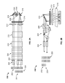
- FIG. 1A is an example Y-Z layout 101 of a 1 ⁇ 2 wavelength selective switch 100 on a port switching plane.
- FIG. 1B is an example X-Z layout 103 of the 1 ⁇ 2 wavelength selective switch 100 on a wavelength dispersion plane.
- FIG. 1A and FIG. 1B provide representations of the same wavelength selecting switch 100 from different orientations.
- the wavelength selective switch 100 includes a top layer and a bottom layer for separating the input and output beam paths through the wavelength selective switch 100 .
- the wavelength selective switch 100 includes an optical input port 102 , optically coupled to the top layer, and two offset optical output ports 120 optically coupled to the bottom layer.
- the wavelength selective switch 100 is a 1 ⁇ 2 switch since it contains a single input port and two output ports.
- the input port 102 and output ports 120 can be respectively coupled to optical fibers, e.g., as part of an optical fiber network or one or more fiber devices.
- the wavelength selective switch 100 includes a walk off crystal 104 , half wave plate 105 , beam expander 106 , polarization beam splitter 108 , optical wavelength dispersion element (e.g., grating) 110 , focusing lens 112 , focusing lens 114 , folding optics 116 , and polarization modulator array (e.g., liquid crystal cell array) 118 .
- optical wavelength dispersion element e.g., grating
- focusing lens 112 focusing lens 112
- focusing lens 114 focusing lens 114
- folding optics 116 e.g., liquid crystal cell array
- polarization modulator array e.g., liquid crystal cell array
- An input optical beam at the input port 102 can include multiple channels, e.g., for transmitting data.
- Each channel can be a wavelength channel having an optical signal having a different wavelength ( ⁇ ).
- ⁇ can be composed of individual channels having wavelengths ⁇ 1 , ⁇ 2 , ⁇ 3 , ⁇ 4 , and ⁇ 5 .
- the input optical beam can be randomly polarized.
- a polarization mode fiber input to the input port 102 provides an input optical signal having two orthogonal polarizations relative to the path of the input optical beam.
- the randomly polarized input optical signal enters the wavelength selective switch 100 through the input port 102 and then undergoes polarization conditioning.
- Polarization conditioning of the input optical beam is provided by polarization conditioning components including the walk off crystal 104 and the half wave plate 105 .
- the walk off crystal 104 is a birefringence material that decomposes the input optical signal according to polarization.
- the input optical signal is divided into orthogonal polarizations, each following a different path through the walk off crystal.
- the half wave plate 105 rotates the polarization light output from one of the paths through the walk off crystal 104 by 90 degrees.
- the input optical signal leaves the polarization conditioning as two beams having identical polarization directions.
- the input optical beam is represented by a single known polarization.
- the polarization direction is parallel to a wavelength dispersion plane (X-Z plane) of the wavelength selective switch 100
- the two light beams enter the beam expander 106 (e.g., through the top layer).
- the beam expander 106 can be, for example, a pair of prisms.
- the beam expander 106 is designed to spread out the two light beams from the polarization conditioning by a specified amount as an expanded input beam.
- the beam expander 106 can be designed to expand the light beams along a single axis, e.g., along the X-Z direction.
- the expanded input beam passes through the polarization beam splitter 108 .
- the polarization beam splitter 108 can be positioned such that the expanded input beam passes directly through the polarization beam splitter 108 .
- the polarization beam splitter 108 is only present in the bottom layer of the wavelength selective switch 100 such that the expanded input beam does not pass through the polarization beam splitter 108 along the path of the top layer.
- the expanded input beam is then projected onto the optical wavelength dispersion element 110 .
- the optical wavelength dispersion element 110 can be a grating.
- the grating separates the expanded input beam according to wavelength such that each wavelength follows a distinct path (e.g., a particular angle from the grating).
- the grating can be a diffraction grating that splits and diffracts light into several beams travelling in different directions. The directions of these beams depend on the spacing of the grating and the wavelength of the light so that the grating acts as the dispersive element separating the different wavelength channels of the expanded optical beam.
- Optical components including a focusing lens 112 focuses the wavelength channels along a first axis and the focusing lens 114 focuses the wavelength channels along a second axis.
- focusing lens 112 is one of a pair of cylindrical lenses placed on the plane perpendicular to the plane of wavelength dispersion.
- Focusing lens 114 is a cylindrical lens for the beam focusing on the wavelength dispersion plane and positioned such that the grating 110 is located at a front focus plane of the focusing lens 114 .
- the focusing lenses 112 and 114 can use spherical or other types of lenses instead of cylindrical lenses.
- the result of the focusing lenses 112 and 114 is to map the different wavelength channels into different locations in space at a focus plane of the focusing lens 114 .
- Beam folding optics 116 are provided such that the same optical components can be shared along a return path through the wavelength selective switch to the output ports 120 .
- the polarization modulator array 118 is positioned at the focus plane of optical components including the focusing lens 114 .
- the polarization modulator array 118 can be a liquid crystal cell array that includes a number of separate polarizing modulation cells e.g., pixel cells. Each pixel can be independently controlled such that the pixel either rotates the polarization orientation of light incident on the pixel (e.g., by 90 degrees) or does not change the polarization. For example, electric voltage though a particular cell can cause alignment of the liquid crystal. Whether polarization is rotated or not can depend on whether the liquid crystal is aligned.
- the polarization modulator array 118 can also be a thin film transistor liquid crystal panel or a liquid crystal on silicon.
- Each polarizing modulation cell of the polarization modulator array 118 can be designed to provide polarization control for a specific wavelength channel.
- the polarization modulator array 118 can be configured to independent control the polarization state of each individual wavelength channel according to the desired combination of wavelengths at each polarization state/orientation.
- the polarization modulator array 118 can be programmed to produce particular polarizations of the wavelengths in order to achieve the desired port routing by the polarization beam splitter as described below.
- the polarization switched wavelengths are returned through the focusing lenses 114 and 112 as well as wavelength dispersion element 110 , but at the bottom layer of the wavelength selective switch 100 using the folding optics 116 .
- the light beam with different wavelengths and switched polarization is recombined into a single beam along the same beam path after the grating 110 , since the dispersion is cancelled out by the return trip through the grating 100 .
- the different wavelengths in the polarization switched beam have a polarization coded by the corresponding back end liquid crystal cell pixel.
- the polarization switched beam can include wavelengths having different orthogonal polarizations.
- separate components are present in the return path, e.g., a separate wavelength dispersion element at the bottom layer for recombining the light beams.
- the wavelength switched beam enters the polarization beam splitter 108 .
- the polarization beam splitter 108 is positioned at a front end of the wavelength selective switch and routes the wavelength channels into different output beam paths based on their polarization state.
- a polarization beam splitter separates an incident beam into two beams of differing linear polarization which follow different paths through the polarization beam splitter.
- the polarization bema splitter can be, for example, a thin film coated polarization selective prism, a birefringence crystal walk off block, or a birefringence crystal prism.
- the polarization switched beam can include five wavelength channels.
- wavelength channels ⁇ 1 , ⁇ 3 , and ⁇ 4 can have a first polarization and wavelength channels ⁇ 2 and ⁇ 5 can have a second, orthogonal, polarization.
- the polarization beam splitter 108 splits wavelength channels ⁇ 1 , ⁇ 3 , and ⁇ 4 to a first output beam path and wavelength channels ⁇ 2 and ⁇ 5 to a second output beam path. Consequently, the polarization beam splitter 108 provides port routing for an optical beam having different switched polarization components (e.g., different wavelength channels having different polarization). The port routing is performed separate from the liquid crystal switching core on a recombined switched optical beam.
- each output beam path passes through the beam expander 106 to reverse the prior expansion of the input optical beam, e.g., to convert the light size back to a size for output through an optical fiber.
- the light from the output beam paths then pass again through polarization conditioning optics to combine each respective beam for passing through a particular output port 120 .
- a single input beam having five different wavelength channels has be separated such that a first output port receives wavelength channels ⁇ 1 , ⁇ 3 , and ⁇ 4 and the second output port receives wavelength channels ⁇ 2 and ⁇ 5 .
- the polarization modulator array 118 rotates the polarization of light incident on a particular pixel by +/ ⁇ 45 degrees instead of 0 degrees or 90 degrees.
- the polarization beam splitter 108 will send half of the corresponding light along each path. Consequently, the wavelength selective switch 100 can be used as a splitter that separates an incoming light beam having multiple channels into two separate light beams having equal amounts of each of the multiple channels.
- a linear wavelength selective switch is provided such that beam folding optics 116 are not necessary.
- the input port can be at one side of the wavelength selective switch and the output ports can be on an opposite side.
- a transmissive liquid crystal cell array can pass switched wavelengths from an input side to an output side.
- the polarization beam splitter need only be present on the output side in order to provide port routing for the output switched wavelengths.
- Other components can be duplicated on the input and output sides of the liquid crystal cell array (e.g., two optical wavelength dispersion elements, one on each side).
- FIG. 2A is an example Y-Z layout 201 of a 1 ⁇ 4 wavelength selective switch 200 on a port switching plane.
- FIG. 2B is an example X-Z layout 203 of the 1 ⁇ 4 wavelength selective switch 200 on a wavelength dispersion plane.
- FIG. 2A and FIG. 2B provide representations of the same wavelength selecting switch 200 from different orientations.
- the wavelength selective switch 200 includes a top layer, a middle layer, and a bottom layer for separating the input and output beam paths through the wavelength selective switch 200 .
- an optical input port 202 is optically coupled to the top layer
- two optical output ports 220 are optically coupled to the middle layer the beams of these two output ports are overlapped in space but with orthogonal polarizations.
- Two other offset optical output ports 220 are optically coupled to the bottom layer.
- there are two offset beams for each port in the region between input and output polarization conditioning optics e.g., walk off crystal 204 ).
- the wavelength selective switch 200 is a 1 ⁇ 4 switch since it contains a single input port and two output ports on the middle layer and two output ports on the bottom layer.
- the input port 202 and output ports 220 can be coupled to respective optical fibers.
- the wavelength selective switch is bi-directional such that the wavelength selective switch 200 becomes a 4 ⁇ 1 switch having four input ports and one output port.
- the wavelength selective switch 200 includes a walk off crystal 204 , half wave plate 205 , beam expander 206 , polarization beam splitter 208 , optical wavelength dispersion element (e.g., grating) 210 , focusing lens 212 , focusing lens 214 , and folding optics 216 as described above with respect to wavelength selective switch 100 .
- the wavelength selective switch 200 includes an additional switch pair including a birefringence prism 222 and a second polarization modulator array where the birefringence prism 222 is positioned between the polarization modulator arrays.
- the birefringence prism 222 can be, for example, a Wollaston prism.
- the Wollaston prism separates light into two orthogonal linearly polarized beams that diverge at a specified angle from each other.
- the first polarization modulator array e.g., liquid crystal cell array
- the coded polarizations for light from the first polarization modulator array 224 are separated by the birefringence prism 222 that diverge at a specified angle from each other based on their coded polarization. All p-polarized light is propagated along one specific angle, and all s-polarized light is propagated along another specific angle. All light beams that are propagated along two different angles are sent to the second polarization modulator array 226 for further polarization coding.
- the second polarization modulator array 226 again either changes or maintains the polarization of particular wavelengths depending on a particular coding for the second polarization modulator array 226 .
- the beams with different specific propagation angles will be sent to different layers (middle and bottom layers) on the Y-Z port switching plane, regardless of their polarization states coded by the second polarization modulator array 226 .
- the beam layer positions are determined by the polarization coding on the first liquid polarization modulator array 224 and birefringence prism 222 .
- the beams on the middle layer or bottom layer can be of different polarizations that depend on the polarization coding by the second polarization modulator array 226 .
- the respective beam paths enter the polarization beam splitter 208 which separates both middle layer and bottom layer beams into two output beam paths that are routed to respective output ports 220 on the X-Z plane.
- the polarization beam splitter 208 For each of the two layers of output (middle and bottom layer) on the Y-Z plane there are two branches of output beam paths on X-Z plane.
- an input beam can have four different wavelength channels.
- the first polarization modulator array 224 can result in a first and second wavelength channels having a first polarization and a third and fourth wavelength channels having a second polarization.
- the light beams for the wavelength channels are then incident on the switch pair.
- the prism 222 directs the first and second wavelength channels having the first polarization to a first portion of the second polarization modulator array 226 .
- the prism 222 directs the third and fourth wavelength channels having the second polarization to a second portion of the second polarization modulator array 226 .
- the wavelengths are still separate such that each is incident on a respective pixel cell of the second liquid crystal cell array 226 .
- the first and second polarization modulator arrays can also be a thin film transistor liquid crystal panel or a liquid crystal on silicon, or a combination of these.
- the output path on the middle layer can include the first and second wavelength channels and the bottom layer can include the third and fourth wavelength channels.
- the first and second wavelength channels can have different polarizations and the third and fourth wavelength channels can have different polarizations. Consequently, the polarization beam splitter can direct the first, second, third, and fourth wavelength channels to separate output paths optically coupled to respective output ports 220 .
- the input optical signal can include additional wavelengths and based on the coding of the two polarization modulator arrays, various combinations of wavelength channels can be switched to each of the individual output ports.
- FIG. 3A is an example Y-Z layout 301 of a 1 ⁇ 8 wavelength selective switch 300 on a port switching plane.
- FIG. 3B is an example X-Z layout 303 of the 1 ⁇ 8 wavelength selective switch 300 on a wavelength dispersion plane.
- FIG. 3A and FIG. 3B provide representations of the same wavelength selecting switch 300 from different orientations.
- the wavelength selective switch 300 includes a top layer, and four output layers for separating the input and output beam paths through the wavelength selective switch 300 .
- an optical input port 302 is optically coupled to the top layer
- two offset optical output ports 320 are optically coupled to a first output layer
- two optical output ports 320 are optically coupled to a second output layer
- two optical output ports 320 overlapped in space but with orthogonal polarization
- two optical output ports 320 overlapped in space but with orthogonal polarization, are optically coupled to a fourth output layer.
- the overlapped output ports on each output layers on Y-Z port switching plane will be separated on X-Z dispersion plane after the polarization a beam splitter 308 .
- the wavelength selective switch 300 is a 1 ⁇ 8 switch since it contains a single input port and eight output ports.
- the input port 302 and output ports 320 can be coupled to respective optical fibers.
- the wavelength selective switch is bi-directional such that the wavelength selective switch 100 becomes an 8 ⁇ 1 switch having eight input ports and 1 output port.
- the wavelength selective switch 300 includes a walk off crystal 304 , half wave plate 305 , beam expander 306 , polarization beam splitter 308 , optical wavelength dispersion element (e.g., grating) 310 , focusing lens 312 , focusing lens 314 , and folding optics 316 as described above with respect to wavelength selective switch 100 .
- optical wavelength dispersion element e.g., grating
- the wavelength selective switch 300 further includes two switch pairs including respective birefringence prisms and polarization modulator arrays.
- the first switch pair includes a first birefringence prism 322 positioned between a first polarization modulator array 324 and a second polarization modulator array 326 .
- the second switch pair includes a second birefringence prism 328 positioned between the second polarization modulator array 326 and a third polarization modulator array 330 .
- the birefringence prisms 322 and 328 can be, for example, Wollaston prisms.
- the switching provided by the combination of polarization modulator arrays (e.g., liquid crystal cell arrays) and birefringence prisms is similar to that described with respect to wavelength selective switch 200 , only with an additional layer of components.
- the combination of polarization modulator array ( 324 and 326 ) and birefringence prisms ( 322 and 328 ) can provide light directed to light paths of the four output layers based on the polarization coding for each wavelength channel on polarization modulator array 324 and 326 . Based on polarization differences coded for each wavelength on polarization modulator array 330 , the two space-overlapped output ports on each output layer will be further separated on X-Z dispersion plane after the polarization beam splitter 308 .
- the structure can be further expanded with additional switch pairs to facilitate 1 ⁇ n (or n ⁇ 1) wavelength selective switching.
- FIG. 4 is a flow diagram of an example method 400 for wavelength selective switching.
- the optical beam is received ( 402 ).
- the optical beam includes a plurality of wavelengths (e.g., multiple wavelength channels each encoded with different information). Additionally, the optical beam is polarized in different directions. In some implementations, the optical beam is randomly polarized based on the type of optical fiber providing the optical beam.
- the received optical beam is conditioned to provide uniform polarization ( 404 ).
- uniform polarization For example, a combination of a birefringence walk off plate and a half wave plate can be used to convert the received optical beam into a single polarization orientation.
- Other components that can be used for polarization conditioning include a polarization beam splitter and half wave plate or a birefringence prism and a half wave plate.
- the uniformly polarized optical beam is separated according to wavelength ( 406 ) using wavelength dispersion optics.
- the separation can include using a grating that passes the incident light in different dispersed directions based on wavelength.
- the separation includes first expanding the uniformly polarized optical beam to spread the beam over a larger area.
- Each separated wavelengths is directed (e.g., using one or more lenses) to a particular cell of switching components ( 408 ).
- a grating can provide angular separation of wavelengths while the one or more lenses convert the angular separation into spatial separation on a focus plane of a first component of the switching array.
- the switching components can include a first polarization modulator array having a multiple polarization modulation cells and one or more switch pairs depending on the configuration of the wavelength selective switch.
- Each polarization modulation cell can be independently controlled to either rotate the polarization orientation (e.g., by 90 degrees) of light incident on the cell or to maintain the polarization orientation.
- each cell is a pixel of a liquid crystal cell array that can be configured provide different polarization orientations for specific wavelengths of light.
- one or more switch pairs can be provided as described above.
- the output light from the switching array is merged into one or more output optical beams ( 410 ).
- the output light from the switching array can follow a reverse path through the grating in order to recombine the wavelengths to an output beam path.
- Each wavelength channel of the one or more output optical beams is routed to a particular output port based on the corresponding polarization orientation ( 412 ).
- a polarization beam splitter can provide port routing by directing wavelength channels to different output ports based on polarization. For example, in a 1 ⁇ 2 wavelengths selective switch, wavelength channels having a first polarization orientation can be directed to a first output path optically coupled to a first output port and wavelength channels having a second polarization orientation can be directed to a second output path optically coupled to a second output port.
Landscapes
- Physics & Mathematics (AREA)
- General Physics & Mathematics (AREA)
- Optics & Photonics (AREA)
- Engineering & Computer Science (AREA)
- Computer Networks & Wireless Communication (AREA)
- Nonlinear Science (AREA)
- Signal Processing (AREA)
- Optical Modulation, Optical Deflection, Nonlinear Optics, Optical Demodulation, Optical Logic Elements (AREA)
- Liquid Crystal (AREA)
Abstract
Description
Claims (15)
Priority Applications (4)
| Application Number | Priority Date | Filing Date | Title |
|---|---|---|---|
| US13/418,274 US8867016B2 (en) | 2012-03-12 | 2012-03-12 | Wavelength selective switch |
| EP12178743.6A EP2639611B1 (en) | 2012-03-12 | 2012-07-31 | Wavelength selective switch |
| EP16206702.9A EP3206065A1 (en) | 2012-03-12 | 2012-07-31 | Wavelength selective switch |
| CN201210296547.1A CN103308987B (en) | 2012-03-12 | 2012-08-20 | Wavelength selective switch |
Applications Claiming Priority (1)
| Application Number | Priority Date | Filing Date | Title |
|---|---|---|---|
| US13/418,274 US8867016B2 (en) | 2012-03-12 | 2012-03-12 | Wavelength selective switch |
Publications (2)
| Publication Number | Publication Date |
|---|---|
| US20130235283A1 US20130235283A1 (en) | 2013-09-12 |
| US8867016B2 true US8867016B2 (en) | 2014-10-21 |
Family
ID=47076058
Family Applications (1)
| Application Number | Title | Priority Date | Filing Date |
|---|---|---|---|
| US13/418,274 Active 2032-09-15 US8867016B2 (en) | 2012-03-12 | 2012-03-12 | Wavelength selective switch |
Country Status (3)
| Country | Link |
|---|---|
| US (1) | US8867016B2 (en) |
| EP (2) | EP2639611B1 (en) |
| CN (1) | CN103308987B (en) |
Cited By (3)
| Publication number | Priority date | Publication date | Assignee | Title |
|---|---|---|---|---|
| WO2016128841A3 (en) * | 2015-02-09 | 2016-10-20 | Nistica, Inc. | Multi-point, contentioinless wavelength selective switch (wss) |
| US11722236B1 (en) * | 2022-04-05 | 2023-08-08 | Ii-Vi Delaware, Inc. | Polarization-maintaining wavelength selective switch for free-space optical communication |
| US20240036260A1 (en) * | 2021-01-19 | 2024-02-01 | O-Net Communications (Usa) Inc. | Wavelength selective switch |
Families Citing this family (10)
| Publication number | Priority date | Publication date | Assignee | Title |
|---|---|---|---|---|
| US9432750B1 (en) * | 2013-04-19 | 2016-08-30 | Wavexing, Inc. | Contentionless N×M wavelength cross connect |
| US20160124155A1 (en) * | 2013-06-06 | 2016-05-05 | Sumitomo Electric Industries, Ltd. | Wavelength selection switch and control method for phase modulation element |
| JP6295584B2 (en) * | 2013-10-08 | 2018-03-20 | 住友電気工業株式会社 | Optical unit and optical device |
| US9341870B1 (en) * | 2014-11-26 | 2016-05-17 | Nistica, Inc. | Launch optics with optical path compensation for a wavelength selective switch |
| CN105182473B (en) * | 2015-09-18 | 2018-11-09 | 北京邮电大学 | A kind of wavelength selective optical disabler |
| WO2017147770A1 (en) * | 2016-03-01 | 2017-09-08 | 肖峰 | Wavelength selection switch apparatus, communication device and wavelength switching method |
| CN109791257B (en) * | 2016-10-07 | 2020-06-05 | 光联通讯技术有限公司美国分部 | Wavelength selective switch |
| CN106772820A (en) * | 2016-12-16 | 2017-05-31 | 中央民族大学 | High port number wavelength-selective switches and its control method based on optical beam-expanding unit |
| US11067855B2 (en) * | 2019-02-11 | 2021-07-20 | Facebook Technologies, Llc | Apparatus and methods for aligning photopolymers using an asymmetrically focused beam |
| CN113805279B (en) * | 2021-09-29 | 2023-11-24 | 福州高意通讯有限公司 | Integrated device with isolation and wavelength division multiplexing functions |
Citations (9)
| Publication number | Priority date | Publication date | Assignee | Title |
|---|---|---|---|---|
| WO1994028456A1 (en) | 1993-06-01 | 1994-12-08 | Bell Communications Research, Inc. | Frequency-selective optical switch using polarization rotation |
| US6285500B1 (en) | 1999-06-29 | 2001-09-04 | Corning Incorporated | Wavelength selective switch |
| US6810169B2 (en) | 2000-02-17 | 2004-10-26 | Jds Uniphase Inc. | Wavelength switch with independent channel equalization |
| US6947628B1 (en) | 2001-08-30 | 2005-09-20 | Avanex Corporation | Dynamic wavelength-selective optical add-drop switches |
| WO2007029260A2 (en) | 2005-09-08 | 2007-03-15 | Xtellus Inc. | Optical wavelength selective router |
| US7454100B2 (en) * | 2005-05-19 | 2008-11-18 | Xtellus, Inc. | Single-pole optical wavelength selector |
| US7468840B2 (en) | 2001-10-09 | 2008-12-23 | Xtellus, Inc. | Wavelength selective optical switch |
| US7492986B1 (en) | 2004-12-23 | 2009-02-17 | Coadna Photonics, Inc. | Apparatus and method for optical switching with liquid crystals and birefringent wedges |
| WO2010146589A1 (en) | 2009-06-18 | 2010-12-23 | Oclaro (New Jersey) Inc | Multiple port wavelength selectable router |
Family Cites Families (1)
| Publication number | Priority date | Publication date | Assignee | Title |
|---|---|---|---|---|
| US5946116A (en) * | 1997-04-02 | 1999-08-31 | Wu; Kuang-Yi | 1 X N digitally programmable optical routing switch |
-
2012
- 2012-03-12 US US13/418,274 patent/US8867016B2/en active Active
- 2012-07-31 EP EP12178743.6A patent/EP2639611B1/en active Active
- 2012-07-31 EP EP16206702.9A patent/EP3206065A1/en not_active Withdrawn
- 2012-08-20 CN CN201210296547.1A patent/CN103308987B/en active Active
Patent Citations (10)
| Publication number | Priority date | Publication date | Assignee | Title |
|---|---|---|---|---|
| WO1994028456A1 (en) | 1993-06-01 | 1994-12-08 | Bell Communications Research, Inc. | Frequency-selective optical switch using polarization rotation |
| US6285500B1 (en) | 1999-06-29 | 2001-09-04 | Corning Incorporated | Wavelength selective switch |
| US6810169B2 (en) | 2000-02-17 | 2004-10-26 | Jds Uniphase Inc. | Wavelength switch with independent channel equalization |
| US6947628B1 (en) | 2001-08-30 | 2005-09-20 | Avanex Corporation | Dynamic wavelength-selective optical add-drop switches |
| US7468840B2 (en) | 2001-10-09 | 2008-12-23 | Xtellus, Inc. | Wavelength selective optical switch |
| US7492986B1 (en) | 2004-12-23 | 2009-02-17 | Coadna Photonics, Inc. | Apparatus and method for optical switching with liquid crystals and birefringent wedges |
| US7454100B2 (en) * | 2005-05-19 | 2008-11-18 | Xtellus, Inc. | Single-pole optical wavelength selector |
| WO2007029260A2 (en) | 2005-09-08 | 2007-03-15 | Xtellus Inc. | Optical wavelength selective router |
| US7822303B2 (en) * | 2005-09-08 | 2010-10-26 | Oclaro (New Jersey), Inc. | Optical wavelength selective router |
| WO2010146589A1 (en) | 2009-06-18 | 2010-12-23 | Oclaro (New Jersey) Inc | Multiple port wavelength selectable router |
Non-Patent Citations (2)
| Title |
|---|
| Communication in European Application No. 12 178 743.6, mailed May 16, 2013, 10 pages. |
| European Search Report dtd. May 8, 2013 from Application No. 12178743.6, pp. 1-4. |
Cited By (7)
| Publication number | Priority date | Publication date | Assignee | Title |
|---|---|---|---|---|
| WO2016128841A3 (en) * | 2015-02-09 | 2016-10-20 | Nistica, Inc. | Multi-point, contentioinless wavelength selective switch (wss) |
| US9661406B2 (en) | 2015-02-09 | 2017-05-23 | Nistica, Inc. | Multipoint, contentionless wavelength selective switch (WSS) |
| US10129615B2 (en) | 2015-02-09 | 2018-11-13 | Nistica, Inc. | Multipoint, contentionless wavelength selective switch (WSS) |
| US10567856B2 (en) | 2015-02-09 | 2020-02-18 | Molex, Llc | Multipoint, contentionless wavelength selective switch (WSS) |
| US20240036260A1 (en) * | 2021-01-19 | 2024-02-01 | O-Net Communications (Usa) Inc. | Wavelength selective switch |
| US11722236B1 (en) * | 2022-04-05 | 2023-08-08 | Ii-Vi Delaware, Inc. | Polarization-maintaining wavelength selective switch for free-space optical communication |
| US20230344542A1 (en) * | 2022-04-05 | 2023-10-26 | Ii-Vi Delaware, Inc. | Polarization-maintaining wavelength selective switch for free-space optical communication |
Also Published As
| Publication number | Publication date |
|---|---|
| CN103308987A (en) | 2013-09-18 |
| EP2639611A1 (en) | 2013-09-18 |
| EP3206065A1 (en) | 2017-08-16 |
| EP2639611B1 (en) | 2016-12-28 |
| US20130235283A1 (en) | 2013-09-12 |
| CN103308987B (en) | 2016-11-23 |
Similar Documents
| Publication | Publication Date | Title |
|---|---|---|
| US8867016B2 (en) | Wavelength selective switch | |
| US9927577B2 (en) | 2×2 wavelength selective switch array | |
| US10620374B2 (en) | Wavelength selective switch | |
| US6690854B2 (en) | Optical wavelength division multiplexer | |
| US10495819B2 (en) | Optical arrangement for managing diversity and isolation between ports in a wavelength selective switch | |
| US8203691B2 (en) | High extinction ratio liquid crystal optical switch | |
| US20050036202A1 (en) | Wavelength selective optical switch | |
| US9864148B1 (en) | Optical arrangement for suppressing outerband crosstalk in a wavelength selective switch | |
| US20100214527A1 (en) | Liquid crystal optical switch for optical signal having arbitrary polarization | |
| US10393968B1 (en) | Apparatus for optical switching with transmissional and reflective polarization modulators | |
| KR20180116046A (en) | Wavelength selective switch |
Legal Events
| Date | Code | Title | Description |
|---|---|---|---|
| AS | Assignment |
Owner name: OPLINK COMMUNICATIONS, INC., CALIFORNIA Free format text: ASSIGNMENT OF ASSIGNORS INTEREST;ASSIGNORS:MAO, HONGWEI;GONG, LIFU;ZHU, TIAN;AND OTHERS;SIGNING DATES FROM 20120215 TO 20120217;REEL/FRAME:027926/0984 |
|
| STCF | Information on status: patent grant |
Free format text: PATENTED CASE |
|
| AS | Assignment |
Owner name: OPLINK COMMUNICATIONS, LLC, CALIFORNIA Free format text: CHANGE OF NAME;ASSIGNOR:OPLINK COMMUNICATIONS, INC.;REEL/FRAME:041665/0728 Effective date: 20150121 |
|
| MAFP | Maintenance fee payment |
Free format text: PAYMENT OF MAINTENANCE FEE, 4TH YEAR, LARGE ENTITY (ORIGINAL EVENT CODE: M1551) Year of fee payment: 4 |
|
| MAFP | Maintenance fee payment |
Free format text: PAYMENT OF MAINTENANCE FEE, 8TH YEAR, LARGE ENTITY (ORIGINAL EVENT CODE: M1552); ENTITY STATUS OF PATENT OWNER: LARGE ENTITY Year of fee payment: 8 |
|
| AS | Assignment |
Owner name: OPLINK COMMUNICATIONS US DIVISION, LLC, CALIFORNIA Free format text: CONVERSION;ASSIGNOR:OPLINK COMMUNICATIONS US DIVISION, LLC;REEL/FRAME:065036/0896 Effective date: 20190101 Owner name: MOLEX, LLC, ILLINOIS Free format text: MERGER;ASSIGNOR:OPLINK COMMUNICATIONS US DIVISION, LLC;REEL/FRAME:065039/0573 Effective date: 20190401 Owner name: OPLINK COMMUNICATIONS US DIVISION, LLC, CALIFORNIA Free format text: MERGER;ASSIGNOR:OPLINK COMMUNICATIONS, LLC;REEL/FRAME:065039/0555 Effective date: 20170725 Owner name: OPLINK COMMUNICATIONS, LLC, CALIFORNIA Free format text: CONVERSION;ASSIGNOR:OPLINK COMMUNICATIONS, LLC;REEL/FRAME:065036/0757 Effective date: 20170718 |