US8863734B2 - Gas grill - Google Patents
Gas grill Download PDFInfo
- Publication number
- US8863734B2 US8863734B2 US12/325,688 US32568808A US8863734B2 US 8863734 B2 US8863734 B2 US 8863734B2 US 32568808 A US32568808 A US 32568808A US 8863734 B2 US8863734 B2 US 8863734B2
- Authority
- US
- United States
- Prior art keywords
- grill
- temperature
- burner
- grilling
- fuel flow
- Prior art date
- Legal status (The legal status is an assumption and is not a legal conclusion. Google has not performed a legal analysis and makes no representation as to the accuracy of the status listed.)
- Active, expires
Links
Images


Classifications
-
- A—HUMAN NECESSITIES
- A47—FURNITURE; DOMESTIC ARTICLES OR APPLIANCES; COFFEE MILLS; SPICE MILLS; SUCTION CLEANERS IN GENERAL
- A47J—KITCHEN EQUIPMENT; COFFEE MILLS; SPICE MILLS; APPARATUS FOR MAKING BEVERAGES
- A47J37/00—Baking; Roasting; Grilling; Frying
- A47J37/06—Roasters; Grills; Sandwich grills
- A47J37/07—Roasting devices for outdoor use; Barbecues
- A47J37/0704—Roasting devices for outdoor use; Barbecues with horizontal fire box
- A47J37/0713—Roasting devices for outdoor use; Barbecues with horizontal fire box with gas burners
-
- A—HUMAN NECESSITIES
- A47—FURNITURE; DOMESTIC ARTICLES OR APPLIANCES; COFFEE MILLS; SPICE MILLS; SUCTION CLEANERS IN GENERAL
- A47J—KITCHEN EQUIPMENT; COFFEE MILLS; SPICE MILLS; APPARATUS FOR MAKING BEVERAGES
- A47J37/00—Baking; Roasting; Grilling; Frying
- A47J37/06—Roasters; Grills; Sandwich grills
- A47J37/07—Roasting devices for outdoor use; Barbecues
- A47J37/0786—Accessories
-
- Y—GENERAL TAGGING OF NEW TECHNOLOGICAL DEVELOPMENTS; GENERAL TAGGING OF CROSS-SECTIONAL TECHNOLOGIES SPANNING OVER SEVERAL SECTIONS OF THE IPC; TECHNICAL SUBJECTS COVERED BY FORMER USPC CROSS-REFERENCE ART COLLECTIONS [XRACs] AND DIGESTS
- Y10—TECHNICAL SUBJECTS COVERED BY FORMER USPC
- Y10T—TECHNICAL SUBJECTS COVERED BY FORMER US CLASSIFICATION
- Y10T137/00—Fluid handling
- Y10T137/8593—Systems
- Y10T137/87096—Valves with separate, correlated, actuators
-
- Y—GENERAL TAGGING OF NEW TECHNOLOGICAL DEVELOPMENTS; GENERAL TAGGING OF CROSS-SECTIONAL TECHNOLOGIES SPANNING OVER SEVERAL SECTIONS OF THE IPC; TECHNICAL SUBJECTS COVERED BY FORMER USPC CROSS-REFERENCE ART COLLECTIONS [XRACs] AND DIGESTS
- Y10—TECHNICAL SUBJECTS COVERED BY FORMER USPC
- Y10T—TECHNICAL SUBJECTS COVERED BY FORMER US CLASSIFICATION
- Y10T137/00—Fluid handling
- Y10T137/8593—Systems
- Y10T137/87265—Dividing into parallel flow paths with recombining
Definitions
- the exemplary embodiments of the invention generally relate to gas grills. More particularly, the exemplary embodiments relate to control systems for gas grills.
- Conventional grills such as for example, outdoor gas grills are generally controlled manually by a user using mechanical flow valves.
- a gas flow control knob associated with a burner of the grill. This allows more or less gas to flow through the burner.
- the user generally adjusts the flames based on some visual indicator such as a flare-up due to, for example, dripping grease or burning or charring of the food being cooked.
- the flame adjustments are often made continually throughout the grilling process to improve the cooking performance of the grill.
- control of the gas flow control knob and the valve may be inconsistent between the different users of the grill. This often results in food that is not consistently cooked.
- the exemplary embodiments overcome one or more of the above or other disadvantages known in the art.
- the gas grill has a cooking surface.
- the control system includes at least two fuel flow valves located between a fuel source and at least one grill burner, a user interface unit configured to receive grill operation settings, at least one temperature sensor disposed adjacent to the cooking surface and configured to detect at least a grill operating temperature and a control unit configured to, receive the grill operation settings from the user interface unit, receive the grill operating temperature from the at least one temperature sensor, and automatically control the at least one fuel flow valve for modulating the amount of fuel delivered to the at least one grill burner to maintain the grill operating temperature at a predetermined temperature based on the operation settings and the grill operating temperature.
- the gas grill includes a plurality of grilling zones each having at least one burner and a cooking surface, a temperature sensor located within each of the grilling zones and adjacent to the respective cooking surface, the temperature sensor being configured to detect an operating temperature of a respective one of the grilling zones, a user interface for receiving grill operating settings and a control unit configured to automatically control a temperature of each of the grilling zones based on a respective operating temperature of the grilling zones and the grill operating settings.
- Still another aspect of the exemplary embodiments relates to a method for controlling a gas grill.
- the method comprises automatically modulating at least one burner in a respective grilling zone of the gas grill between high and low burner settings depending on at least a comparison between a grill operating temperature and a predetermined grill temperature set point.
- FIGS. 1A and 1B are respectively schematic illustrations of a grill rack area and a front view of a gas grill in accordance with an exemplary embodiment
- FIG. 2 is a schematic block diagram of the gas grill of FIGS. 1A and 1B ;
- FIG. 3 is a schematic block diagram of a control system for the gas grill of FIGS. 1A and 1B ;
- FIGS. 4A and 4B are schematic illustrations of exemplary user interface units for a gas grill in accordance with an exemplary embodiment
- FIGS. 5A-5E are schematic illustrations of portions of the exemplary user interface unit of FIG. 4A ;
- FIG. 6 is an exemplary illustration of a portion of the gas grill of FIGS. 1A and 1B ;
- FIG. 7 is a schematic cross-sectional illustration of a portion of the gas grill of FIGS. 1A and 1B ;
- FIG. 8 is an exemplary illustration of a portion of a gas grill monitoring system in accordance with an exemplary embodiment
- FIGS. 9-13 are schematic illustration of exemplary control system configurations for the gas grill of FIGS. 1A and 1B ;
- FIG. 14 illustrates a schematic side view of a grill in two configurations in accordance with an exemplary embodiment
- FIG. 15 illustrates one exemplary food temperature distribution of a grill in accordance with an exemplary embodiment
- FIG. 16 is an exemplary graph illustrating a relationship between preheat time, cooking time and grill temperature
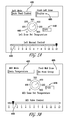
- FIGS. 17-19 illustrate exemplary time-to-preheat graphs for different grilling zones of the grill shown in FIGS. 1A and 1B ;
- FIG. 20 is a graph illustrating exemplary grill temperatures for different grilling zones in accordance with an exemplary embodiment
- FIG. 21 is a graph illustrating exemplary grill cleaning temperatures for different grilling zones in accordance with an exemplary embodiment
- FIG. 22 is a graph illustrating exemplary grilling zone temperatures in accordance with an exemplary embodiment.
- FIGS. 23-25 are graphs illustrating exemplary valve settings for different grilling zones of the grill in FIGS. 1A and 1B .
- FIG. 1A illustrates a front view of an exemplary gas grill 100 .
- FIG. 1B is a schematic top view of the grilling area 140 of grill 100 with the cover removed.
- the grill 100 may be any suitable grill having any suitable size and/or shape.
- the grill 100 is described as a gas grill that is capable of using liquid propane (LP) or natural gas as a fuel source.
- LP liquid propane
- the grill 100 may use any suitable fuel source.
- the grill flames and/or temperature are automatically controlled through a control unit of the grill by controlling the fuel input rate to the burners 910 - 912 (see FIG. 9 ).
- the grill 100 may also include manual controls so that a user of the grill 100 can manually control the grill flames and/or temperature in conventional fashion.
- the grill 100 may include any suitable heat sensing devices or temperature sensors such as, for example, resistance thermal devices (RTDs).
- RTDs such as RTDs 150 a - 150 c , are installed in close proximity or adjacent to the grilling/cooking surface so that each cooking zone within the grilling area has its own RTD (see e.g. FIG. 6 illustrating RTD 150 a , 150 b located, for example, underneath the grilling racks 600 ).
- RTDs resistance thermal devices
- RTDs 150 a - 150 c are installed in close proximity or adjacent to the grilling/cooking surface so that each cooking zone within the grilling area has its own RTD (see e.g. FIG. 6 illustrating RTD 150 a , 150 b located, for example, underneath the grilling racks 600 ).
- one or more cooking zones may share an RTD.
- the user prior to grilling, sets a predetermined grill temperature (e.g. the grill temperature set point 310 ; see FIG. 3 ) that the grill 100 should reach and maintain throughout cooking.
- a predetermined grill temperature e.g. the grill temperature set point 310 ; see FIG. 3
- Inputs from the RTDs 150 a - 150 c to the grill control unit 330 are evaluated and compared against the grill temperature set point.
- the control unit 330 is configured to change the combustion rate of the fuel via suitable fuel flow valves.
- the control unit 330 may notify the user via any suitable audible or visual alerts that the grill is preheated and ready for use.
- the gas grill control system described herein may also provide for flare-up sensing/turndown, remote sensing, flame sensing and auto-turndown. Flare-ups on gas grills are common and occur when grease and food byproducts drop or collect on the grill burners/flames. The increased flames from these flare-ups generally propagate upwards and can burn the food that is being grilled.
- Flare-up sensing in accordance with the exemplary embodiments actively monitors the grill temperature gradients using the RTDs (more specifically, when the reading of the RTD exceeds a predetermined temperature, then the control unit 330 will conclude that there is a flare-up) so that when a flare-up occurs, the combustion rate of the fuel will be turned down to, for example, a lower setting or even completely off to permit the flame to dissipate.
- the temperature returns to normal (e.g., the grill temperature set point)
- the fuel control valves would return to an optimum setting as determined by the control unit 330 .
- Remote sensing allows a user to obtain feedback from the grill while the user is located in an area remote from the grill such as, for example, when the user walks away from the grill and enters a building structure.
- the control unit 330 may be configured to send out suitable wireless signals to a remote device located in the vicinity of the user to identify to the user the condition or status of the grill and/or food being cooked. Flame sensing to detect or verify the presence of the flame or to detect loss of flame, can be achieved in any suitable manner such as, for example, by noting drastic, unexpected temperature drops during use.
- the grill 100 may include a base 120 , a user interface unit or control panel 110 , a hood 130 and a grilling area 140 .
- the base 120 may have any suitable shape and size for supporting and at least partially housing the cooking area of the grill 100 . It is noted that the base shown in the figures and described herein is merely exemplary in nature and that the base may have any other suitable features and/or components. In this exemplary embodiment, the base 120 is in the form of a cabinet.
- the cabinet may be configured with a storage area for storing, for example, a portable fuel supply 170 , an electrical power source 161 (e.g., battery or other electrical power means) for operation of the grill igniter and/or control system, and housing any suitable components of the grill 100 .
- the grill 100 may include a power cord 160 in lieu of the electrical power source 161 and/or a fuel line 171 for coupling the grill 100 to a stationary or non-portable fuel source.
- the hood 130 may be suitably hinged to the base between an open and closed position (see e.g. FIG. 14 ) to allow for access to the grilling area 140 .
- the grilling area 140 may include any suitable number of grilling zones 140 a - 140 c such that each grilling zone has its own temperature control.
- Each grilling zone 140 a - 140 c includes an RTD 150 a - 150 c located adjacent to its respective grilling surface. The temperature/flame of each grilling zone 140 a - 140 c is controlled through the user interface unit 110 as will be described in greater detail below.
- the grill 100 includes a control unit 330 that is connected to a user interface unit or control panel 210 .
- the control unit 330 may include a motherboard or processor 220 , a relay board/power supply 230 , a memory and other suitable electronics/components and programming for carrying out the control of the grill 100 as described herein.
- Digitally or electronically controlled fuel flow valves 240 such as solenoid valves, and igniters 250 are connected to the relay board 230 which are in turn connected to the burner(s) 260 for each cooking zone 140 a - 140 c .
- the igniters 250 may be any suitable igniters such as for example, spark igniters or glow bars.
- the RTDs may be connected to the control unit 330 and be connected to or located in close proximity or adjacent to the cooking surface of the grill 100 , the burners 260 and/or the food being cooked.
- the RTDs in this exemplary embodiment include grill temperature probe(s) 270 , which may be substantially similar to the RTDs 150 a - 150 c , and the food temperature probe(s) 280 .
- the user sets the grill temperature set point 310 in the control unit 330 through the user interface unit 210 .
- the control unit 330 operates the electronically controlled valves 240 through, for example, the relay board 230 .
- the igniters 250 cause the fuel flowing from the valves 240 to ignite.
- the control unit 330 can monitor the temperature of the grill to check for ignition and operate the igniters 250 accordingly until combustion of the fuel is achieved.
- the amount of fuel flowing into the burners 260 from the valves 240 causes the combustion of fuel in each cooking zone to be adjusted so that the grill temperature set point 310 is reached.
- the combustion of fuel may be controlled at the maximum power or fuel setting.
- the combustion e.g. flames
- suitable power levels such as the maximum power level and a minimum power level (e.g.
- the lowest amount of fuel supplied to the burner to maintain a flame depending on whether the grill temperature is above or below the grill temperature set point 310 .
- the minimum power level is used and when the grill temperature is below the grill temperature set point 310 , the maximum power level is used.
- the term power level is used for exemplary purposes only to describe, for example, the intensity of the combustion at the burner such that the maximum power level indicates the highest level of combustion and the minimum power level indicates the lowest level of combustion without the burner 260 being shut off or extinguished.
- the temperature of the grilling zone and/or food being cooked is monitored by the grill temperature probe 270 and/or the food temperature probe 280 which send corresponding signals to the control unit 330 so that the grill temperature set point 310 can be maintained as described herein.
- the control unit 330 would extinguish the flames of the burners by stopping a flow of fuel into a respective one of the burners 260 until the temperature of the grill, as detected by the RTDs, dropped below the grill temperature set point 310 at which point the burner would be re-ignited to maintain the grill temperature set point 310 .
- the control unit 330 may periodically monitor flame presence through established flame sensing methods such as electronic reigniters that sense voltage changes from the igniter to ground when the flame is present or local temperature sensors located near the gas burner flame ports.
- a user interface may be presented through any suitable display, such as a liquid crystal display, of the user interface unit 210 and may be a “virtual user interface unit” (e.g. no physically turnable knobs or physically depressable buttons) such that operation of the user interface unit is through, for example, touch capabilities of the display and/or a keypad 111 .
- the user interface unit may include a combination of a virtual user interface unit and a physical user interface unit where the user interface unit includes, for example, a touch enabled display, physically turnable knobs, physically depressable buttons and/or any suitable visual display for conveying information to the user.
- the user interface unit may be a physical user interface unit including physically turnable knobs and/or physically depressable buttons (or any other suitable analog mechanical device) and visual information as will be described below with respect to FIG. 4B .
- the analog mechanical devices e.g. knobs and buttons
- the control unit 330 is connected to the control unit 330 in any suitable manner where their analog signal may be converted to a digital or electronic signal for controlling a respective setting of the grill as described herein.
- the user interface unit includes a control section for each cooking zone.
- the controls for each control section 400 - 402 are substantially the same but in alternate embodiments the controls for each control section 400 - 402 may be different from each other.
- each control section 400 - 402 includes a zone temperature indicator 410 for indicating the actual grill temperature at a respective zone, a preheat indicator 480 , a temperature set control knob 445 , a food choice indicator 495 , a heating rate indicator 490 , a time-to-flip indicator 415 , a flare-up indicator 485 , a time to remove food indicator 420 , a grilling mode indicator 430 , a manual control indicator 440 , and timer controls 470 .
- the user interface unit may also includes a grill use selector 450 (e.g.
- the user interface unit may have any suitable controls and/or indicators.
- the indicators may be any suitable visual and/or audible indicators such as for example, any suitable combination of sounds, lights, slider bars and digital readouts.
- the user interface unit may also include a fuel level monitor for monitoring a level of fuel within, for example, the portable (or stationary) fuel supply 170 .
- the grill temperature set point 310 is set through temperature set control knob 445 .
- the control knob may be a physical knob that is grasped and turned by the user for setting the grill temperature.
- the temperature set control knob 445 is turned the grill temperature set point 310 is displayed on digital readout 446 .
- the user interface unit may not include digital readout 446 where the temperature is set, using the temperature gradations located adjacent the temperature set control knob 445 .
- the temperature set control knob 445 for setting the grill temperature set point 310 may be used in conjunction with an automatic temperature setting of the grill as indicated in the grilling mode indicator 430 as shown in FIG. 5B .
- the automatic temperature setting is configured to modulate the combustion of the respective grilling zone burner so that the grill temperature set point 310 is maintained.
- Another grilling mode includes a food optimized or automatic food control mode where a food type (e.g. poultry, pork, beef, fish, etc.) may be selected using the food choice indicator 495 so that the temperature of the grill is automatically maintained at a predetermined programmed temperature for cooking the selected food type as can be seen in FIG. 5A .
- a food type e.g. poultry, pork, beef, fish, etc.
- the grill may also include a manual grilling mode where the temperature of the grill can be manually adjusted through, for example, the manual control indicator 440 such as a slider bar or other suitable control that allows the user to adjust the valve 240 settings at any given time during grilling for controlling the rate of combustion and amount of fuel delivered to the respective grilling zone burner.
- the manual control indicator 440 such as a slider bar or other suitable control that allows the user to adjust the valve 240 settings at any given time during grilling for controlling the rate of combustion and amount of fuel delivered to the respective grilling zone burner.
- the grill status indicators include the temperature of each grilling zone as indicated by the zone temperature indicator 410 and a food probe temperature 500 , each shown in their respective digital readouts.
- the food probe temperature 500 is obtained from the food temperature probes for indicating the temperature of the food being cooked in the respective grilling zone.
- the grill status indicators may also include visual indicators and/or audible tones generated by, for example, any suitable speaker of the user interface unit for indicating the respective grilling zone is preheated (pre-heat indicator 480 ), that there is a flare-up (flare-up indicator 485 ), that it is time to flip the food (time-to-flip indicator 415 ) or that the cooking of the food is completed (time to remove food indicator 420 ).
- An indicator of the valve settings or power may also be included for use, when for example, the grilling mode is set to an automatic mode.
- timer controls 470 for each of the user interface unit sections will be described.
- the timer controls include a timer in the nature of a knob 473 for setting the timer and preferably a display 471 for displaying the set time to the user.
- a timer activation control 472 is also preferably provided for starting and/or stopping the timer.
- the roasting settings may include a roasting control (i.e., the roasting temperature set point knob) 460 and a roasting temperature display 461 substantially similar to temperature set control knob 445 and temperature display 446 described above.
- the roasting settings/controls may also include a timer substantially similar to the timer 470 described above.
- the grill user interface unit may also include an igniter activation control 477 (e.g., a physical or virtual knob or button) to allow a user to manually ignite the grill burners.
- An ignition timing control 492 may also be provided on the user interface unit for controlling the duration of, for example, the igniter spark or igniter operation. It is noted that when the grill is operated in an automatic mode the control unit 330 may be configured to automatically ignite the burner of the respective cooking zone being used.
- the user interface unit may be a virtual user interface unit without any physical knobs, sliders or buttons for a user to adjust.
- suitable controls such as for example, toggle buttons 599 (virtual or physical) may be located adjacent to a corresponding grill setting control to allow the user to select or enter the grill setting.
- toggle buttons 599 virtual or physical
- the user may touch a portion of, for example the touch enabled control screen at a location corresponding to toggle button 599 A ( FIG. 5C ) so that the temperature settings may be scrolled through until the desired temperature is displayed.
- the other grill settings may be set in a substantially similar manner.
- the user interface unit includes a simplified configuration including two physically turnable control knobs 498 , 499 for each user interface unit section 400 - 402 for controlling a respective grilling zone.
- the control knob 498 may be turned or rotated by the user to place the set the grill mode in one of an automatic mode or a manual mode.
- the user may rotate the knob from the off position 498 D to a position between the “lo” and “hi” burner settings 498 A, 498 B for manually controlling the valves 240 for adjusting the intensity of the burner flames.
- the user may turn the control knob 498 from the off position 498 D to the automatic position 498 C which activates the knob 499 .
- the control knob 499 may be rotated by the user to any automatic grilling mode such as those described above.
- the control knob 499 may be used to set the grill temperature set point 310 , to a cleaning mode (e.g. the highest temperature setting to assist in cleaning, for example, grease and food residue from the grill) or a warming mode so that food can be placed within the grill and kept warm.
- the temperature gradations surrounding control knob 499 may also include food indicators to aid the user in selecting a temperature for grilling.
- the food indicators may include pictures of steak, chicken and ribs or any other food item.
- the control knobs 498 , 499 are connected to the control unit 330 so that the control unit can operate the valves 240 in the manner described herein.
- FIG. 7 an exemplary cross section of a portion of the grill 100 is shown in accordance with an exemplary embodiment.
- a portion of the base 120 is shown with the grilling rack 600 installed therein.
- three food temperature probes 701 - 703 substantially similar to the food temperature probes 280 , are shown corresponding to the three grilling zones 140 a - 140 c for exemplary purposes only and it should be understood that in alternate embodiments there may be more or less than three food temperature probes where each grilling zone may have any suitable number of food temperature probes.
- the food temperature probes 701 - 703 are mounted on a moving member 710 .
- the moving member 710 may be connected to an adjustment mechanism 720 so that the height of the food temperature probe tips above the rack 600 may be adjusted.
- the adjustment mechanism 720 may be any suitable device such as, for example, a hand operated crank or an electric motor with suitable transmissions for raising and lowering the moving member 710 and the food temperature probes 701 - 703 relative to the rack 600 .
- the food temperature probes 701 - 703 move as a unit but in alternate embodiments each probe may be mounted to a separate movable member so that the height of each probe can be individually adjusted.
- the rack 600 may be moveable in a manner substantially similar to that described above with respect to the food temperature probes 701 - 703 so that the distance between the food and the burner flames can be adjusted.
- the probes 701 - 703 may be suitably shaped so that as the probe tips are raised above the rack 600 , the probes 701 - 703 penetrate into the food (for obtaining a temperature measurement of the food) without substantially lifting the food off of the rack 600 during penetration.
- the control unit 330 may be configured to raise and lower the food temperature probes 701 - 703 at any suitable times for obtaining the temperature of the food.
- the food temperature probes 701 - 703 may be inserted into the food when the food is placed on the rack 600 (e.g. there may be sensors for sensing food on the rack, which trigger the control unit to raise the food temperature probes).
- the food temperature probes 701 - 703 may be inserted into the food at predetermined time intervals, when the grill hood is closed, upon a user's request, or when a predetermined automatic grilling mode is selected. It should be understood that the food temperature probes 701 - 703 may be retracted below the surface of the rack 600 in any suitable manner to allow the user to flip the food on or remove the food from the rack 600 . For example, when the grill indicates it is time to flip the food via the time-to-flip indicator 415 or that the cooking of the food is complete via the time to remove food indicator 420 , the food temperature probes 701 - 703 may be automatically retracted by the control unit 330 .
- the user may cause the food temperature probes 701 - 703 to be lowered in any suitable manner for flipping or removing the food. It is noted that in the example, shown in FIG. 7 , the food temperature is measured at the probe tip so that a temperature reading is obtained from, for example a center of the food.
- the control unit 330 may be configured to raise the food temperature probes 701 - 703 by a predetermined amount so that the probe tips are located at a suitable location within the food based on, for example, information input into the control unit by the user or through any suitable programming for determining the coolest location within the food along a path of the probe as it is the coolest location within the food that takes the longest to cook.
- the food temperature probes 701 - 703 provide real-time feedback with respect to food temperature that can be used to determine flip or completion of grilling instruction based on, for example, user cooking selections. It should be understood that while the food temperature probes 701 - 703 are described above as being movable, in alternate embodiments the food temperature probes 701 - 703 may be stationary probes having a fixed height relative to the rack 600 for allowing the user to drop food directly on top of the food temperature probes 701 - 703 .
- the grill 100 may include remote sensing capabilities. Any suitable transmitter 801 may be connected to the control unit 330 for transmitting signals pertaining to the functions or status of the grill 100 to a remotely located receiver 800 .
- the transmitter 801 and the receiver 800 in this exemplary embodiment may be configured for wireless communication through any suitable wireless protocol such as, for example, Zigbee®, Bluetooth®, cellular, or other Radio Frequency or short range communication protocols.
- the transmitter 801 and receiver 800 may communicate through a wired communication link.
- the transmitter 801 may transmit any suitable information to the user pertaining to the operation of the grill including, but not limited to, temperature readings (e.g.
- the control unit may also include a portable computer interface (wired or wireless) such that the grill can be controlled through the portable computer (e.g. laptop, handheld computer, etc.) via grilling software program(s) stored within the portable computer.
- control system utilizes a fully electronic user interface.
- control signals are sent from the user controls 998 , 999 A- 999 C to the control unit 330 .
- the control unit 330 analyzes these control signals and controls the fuel flow valves 930 - 950 accordingly so that a desired amount of fuel is delivered to a respective burner 910 - 912 through a fuel orifice 920 located at an end of a respective burner 910 - 912 .
- the fuel flow valves 930 - 950 are illustrated as a multi-solenoid valve but in alternate embodiments the valve(s) may be any suitable electronically controlled valves.
- FIG. 10 another exemplary schematic diagram of a portion of control system for the grill 100 is shown in accordance with an exemplary embodiment.
- a manually operated valve 1040 coupled with a potentiometer is used.
- the knob 998 A may be coupled directly to the manually operated valve 1040 such that as the knob 998 A is turned, the valve 1040 is opened or closed.
- the potentiometer on the valve sends a signal to the control unit 330 indicating the amount the valve is opened.
- a valve such as, for example, a hi-flow solenoid valve 1042 is located downstream (e.g. in the direction of fuel travel) from the manual valve 1040 which directs fuel through a hi-flow fuel orifice 920 U.
- the manual valve 1040 is supplied with fuel from a gas regulator attached to the portable fuel supply 170 .
- the fuel supply is diverted upstream of the manual valve 1040 to another solenoid valve, low-flow valve 1041 , which directs fuel through a low-flow fuel orifice 920 L.
- the fuel from the hi-flow and low-flow orifices 920 U, 920 L are combined and directed toward the burner orifice 920 for introduction into the respective burner 910 - 912 .
- the control unit 330 monitors the position of each valve and appropriately activates the valves according to the user selection input through controls 998 A- 998 C and/or 999 A- 999 C.
- control unit 330 will also evaluate the grill temperatures to determine when to energize the valves.
- both the valves 1041 , 1042 are energized, while the fuel supplied by the manual valve 1040 passes through the hi-flow valve 1042 .
- FIG. 11 an exemplary schematic diagram of a portion of control system for the grill 100 is shown in accordance with an exemplary embodiment.
- the control system of FIG. 11 is substantially similar to the control system described above with respect to FIG. 10 , but in this exemplary embodiment, the hi-flow orifice 920 U directly feeds a hi-flow burner 1110 while the low-flow orifice 920 L directly feeds a low-flow burner 1111 in lieu of mixing the two fuel flows into a single burner.
- separate hi-flow and low-flow burners allows for an optimized burner design as the temperature range between the hi-flow and low-flow burners is much wider than a temperature range obtained with a single burner.
- the dual burner arrangement e.g. hi-flow burner, low-flow burner arrangement
- FIG. 12 yet another exemplary schematic diagram of a portion of control system for the grill 100 is shown in accordance with an exemplary embodiment.
- the control system of FIG. 12 is substantially similar to that described above with respect to FIG. 10 .
- the manual valve 1040 is run in parallel with the valves 1041 , 1042 rather than in series as in FIG. 10 .
- neither valve 1041 , 1042 is energized such that fuel flow is only directed through the manual valve 1040 to the burner orifice 920 .
- FIG. 13 an exemplary schematic diagram of a portion of control system for the grill 100 is shown in accordance with an exemplary embodiment.
- the control system of FIG. 13 is substantially similar to that described above with respect to FIG. 12 .
- the flow through the manual valve 1040 and hi-flow valve 1042 are directed to a hi-flow burner 1110 through orifice 920 U while the fuel from the low-flow valve 1041 is directed into a separate low-flow burner 1111 through orifice 920 L.
- the low-flow valve 1041 would be energized in most modes to allow fuel to flow to low-flow burner 1111 to ensure a minimum flame level for a respective grilling zone.
- the grill 100 may include a smoke control system for controlling smoke and heat when the grill hood 130 is opened.
- a suitable fan unit 1400 such as for example, a squirrel cage fan may be mounted to, for example, a back of the base 120 .
- the hood 130 may be configured so that when the hood 130 is in the open position a channel is formed between the base 120 and the inside of the hood 130 such that the channel runs above the grilling area.
- the fan unit 1400 is configured to pull air from above the grilling area through the channel, so that any smoke and excess heat is drawn to the back of the grill 100 .
- the grill 100 may include suitable sensors for detecting when the hood 130 is in the open position so that the fan unit 1400 can be energized to remove the smoke and excess heat from above the grilling area.
- the function of the fan unit 1400 is known in the art, and therefore will not be discussed further here. It should be understood that the smoke and heat control system shown in FIG. 14 is merely exemplary and that any suitable smoke and heat control system can be employed without departing from the scope of the exemplary embodiments.
- the exemplary embodiments described above provide a grill 100 having separate grilling zone controls that allow a large variation in temperatures between the grilling zones or a substantially uniform (e.g. even) temperature distribution over all of the grilling zones.
- a substantially uniform temperature distribution that can be achieved with the exemplary embodiments
- FIG. 15 the center temperatures (in degrees farenheight) of, for example, fifteen one-quarter inch thick hamburger patties are shown. These center temperatures were obtained with all three grilling zones 140 a - 140 c set to about 425° F. As can be seen in FIG. 15 , the variation in temperature between the fifteen hamburger patties is about 9° F.
- FIG. 16 an exemplary graph illustrating an exemplary relationship between the hamburger grilling time, grill preheat time and grill temperature set point is shown.
- FIGS. 17-19 illustrate exemplary graphs showing exemplary relationships between grilling zone temperature and time with respect to the preheating of the a respective grilling zone. It is noted that each graph illustrates the preheating of only one grilling zone to a temperature of about 175° C. (347° F.) while the other grilling zones remain off or at their lowest burning temperature (e.g. only one grilling zone is active at a time). As can be seen in the figures, the preheat time for all three grilling zones 140 a - 140 c is about 4 minutes when only one grilling zone is active.
- line 1700 represents room temperature
- line 1701 represents the left zone 140 a (zone 1 ) air temperature
- line 1702 represents the middle zone 140 b (zone 2 ) air temperature
- line 1703 represents the left zone 140 a grilling temperature
- line 1704 represents the middle zone 140 b grilling temperature
- line 1705 represents the right zone 140 c (zone 3 ) grilling temperature
- line 1706 represents the right zone 140 c (zone 3 ) air temperature.
- one grilling zone may be set at about 250° F. while another grilling zone may be set at about 500° F.
- FIG. 20 a graph illustrating the grill temperatures versus time for the three grilling zones 140 a - 140 c (zones 1 - 3 respectively) where zone 140 a is set to 375° F., and zones 140 b , 140 c are set to 425° F.
- FIGS. 21-25 the exemplary graphs illustrate the control of the burners in accordance with the exemplary embodiments.
- FIG. 21 illustrates grilling zone temperatures for a cleaning mode of the grill 100 where the temperature in each zone is ramped up to about 550° F. In one exemplary embodiment, after the food is cooked the control unit 330 may automatically ramp the grill temperature to a cleaning temperature to assist in cleaning the grill 100 .
- FIG. 22 illustrates the evenness of the grilling zone temperatures (within about ⁇ 10 degrees) when grilling, for example, six hamburgers, where line 2200 represents zone 140 a , line 2201 represents zone 140 b and line 2202 represents zone 140 c .
- FIGS. 23-25 illustrates the fuel flow valve control of the left grilling zone 140 a ( FIG.
- the flame is shut down or the valve is closed when the grill temperature within the zone exceeds about 50° F. above the grill temperature set point, which in this example is about 375° F. for zone 140 a and about 425° F. for zones 140 b , 140 c .
- the flame is shut down in the event of a flare-up and re-ignites after the grill temperature drops below the set point.
- the exemplary embodiments described herein provide for a grill 100 having automatic or manual control capabilities for separately controlling multiple grilling zones.
- the grill includes alerts for conveying grilling information to the user as well as remote control/alert capabilities.
- Various probes such as the food temperature probes and grill temperature probes described above, provide for evenness of grilling temperatures, substantially no burning of food, preset optimized food cooking settings and flare up sensing.
Abstract
Description
Claims (18)
Priority Applications (2)
| Application Number | Priority Date | Filing Date | Title |
|---|---|---|---|
| US12/325,688 US8863734B2 (en) | 2008-12-01 | 2008-12-01 | Gas grill |
| CA 2674498 CA2674498A1 (en) | 2008-12-01 | 2009-07-31 | Gas grill |
Applications Claiming Priority (1)
| Application Number | Priority Date | Filing Date | Title |
|---|---|---|---|
| US12/325,688 US8863734B2 (en) | 2008-12-01 | 2008-12-01 | Gas grill |
Publications (2)
| Publication Number | Publication Date |
|---|---|
| US20100132692A1 US20100132692A1 (en) | 2010-06-03 |
| US8863734B2 true US8863734B2 (en) | 2014-10-21 |
Family
ID=42221660
Family Applications (1)
| Application Number | Title | Priority Date | Filing Date |
|---|---|---|---|
| US12/325,688 Active 2031-04-12 US8863734B2 (en) | 2008-12-01 | 2008-12-01 | Gas grill |
Country Status (2)
| Country | Link |
|---|---|
| US (1) | US8863734B2 (en) |
| CA (1) | CA2674498A1 (en) |
Cited By (20)
| Publication number | Priority date | Publication date | Assignee | Title |
|---|---|---|---|---|
| US20110088682A1 (en) * | 2007-11-16 | 2011-04-21 | Wolfedale Engineering Limited | Temperature control apparatus and method for a barbeque grill |
| US20140261006A1 (en) * | 2013-03-12 | 2014-09-18 | Grand Mate Co., Ltd. | Temperature-controllable gas grill and the method of controlling grilling temperature |
| US20150136235A1 (en) * | 2012-11-14 | 2015-05-21 | Mindray Ds Usa, Inc. | Electronic and manual backup flow control systems |
| US9585401B2 (en) | 2004-03-23 | 2017-03-07 | The Middleby Corporation | Conveyor oven apparatus and method |
| US9585400B2 (en) | 2004-03-23 | 2017-03-07 | The Middleby Corporation | Conveyor oven apparatus and method |
| US9609981B2 (en) | 2009-08-28 | 2017-04-04 | The Middleby Corporation | Apparatus and method for controlling a conveyor oven |
| US10024548B2 (en) | 2003-02-21 | 2018-07-17 | The Middleby Corporation | Self-cleaning oven |
| WO2019068371A1 (en) | 2017-10-07 | 2019-04-11 | Michael Schunke | Regulatable grilling device |
| US20190277498A1 (en) * | 2018-03-06 | 2019-09-12 | Boneless Grills Sl | Universal device for the automation of gas powered ovens, barbecues and devices |
| US10650621B1 (en) | 2016-09-13 | 2020-05-12 | Iocurrents, Inc. | Interfacing with a vehicular controller area network |
| USD891960S1 (en) | 2018-12-31 | 2020-08-04 | Watts Regulator Co. | Flow monitor |
| USD906144S1 (en) | 2018-12-31 | 2020-12-29 | Watts Regulator Co. | Flow monitor |
| US10920980B2 (en) | 2016-06-14 | 2021-02-16 | The Middleby Corporation | Convection conveyor oven manifold and damper system |
| US11105512B2 (en) | 2018-03-30 | 2021-08-31 | Midea Group Co., Ltd | Method and system for controlling a flow curve of an electromechanical gas valve |
| US11262069B2 (en) | 2020-06-25 | 2022-03-01 | Midea Group Co., Ltd. | Method and system for auto-adjusting an active range of a gas cooking appliance |
| US11317474B2 (en) | 2014-03-14 | 2022-04-26 | Spectrum Brands, Inc. | Wirelessly operable cooking appliance |
| US20220146103A1 (en) * | 2020-11-09 | 2022-05-12 | Jiangsu Jiuhui Technology Co., Ltd. | Gas oven with stations under parallel or synchronous control |
| US20220146102A1 (en) * | 2020-11-09 | 2022-05-12 | Jiangsu Jiuhui Technology Co., Ltd. | Multi-station parallel synchronous and asynchronous control method and system for detachable gas oven |
| US11624508B2 (en) | 2020-01-10 | 2023-04-11 | Weber-Stephen Products Llc | Methods and apparatus to indicate presence of a flame |
| US11754291B2 (en) | 2020-09-28 | 2023-09-12 | Midea Group Co., Ltd. | Modulating oven burner control for gas cooking appliance |
Families Citing this family (40)
| Publication number | Priority date | Publication date | Assignee | Title |
|---|---|---|---|---|
| CN102014713B (en) * | 2007-12-11 | 2014-07-30 | 加兰工商业有限责任公司 | Energy efficient char-broiler |
| WO2009088809A1 (en) * | 2008-01-02 | 2009-07-16 | W.C. Bradley Company | Temperature measurement means for cooking appliances |
| US8931400B1 (en) * | 2009-05-28 | 2015-01-13 | iDevices. LLC | Remote cooking systems and methods |
| CA2726799A1 (en) * | 2010-01-08 | 2011-07-08 | Wolfedale Engineering Limited | Temperature indicator |
| US9427107B2 (en) * | 2011-09-13 | 2016-08-30 | Iot Controls Llc | Automated temperature control system for a solid-fueled cooker |
| FR2991862B1 (en) | 2012-06-15 | 2015-04-24 | Seb Sa | COOKING APPARATUS AND METHOD FOR IMPLEMENTING THE SAME |
| KR101981670B1 (en) * | 2012-12-21 | 2019-05-24 | 삼성전자주식회사 | Gas Oven |
| ES2556616T3 (en) * | 2013-03-08 | 2016-01-19 | Electrolux Appliances Aktiebolag | Operating method of a cooking appliance, control unit and cooking appliance |
| CN105264295B (en) | 2013-03-27 | 2017-09-12 | 伊莱克斯家用产品公司 | Pot based on span from heating-type thermocouple is sensed |
| US9763540B2 (en) * | 2014-04-08 | 2017-09-19 | Seyed Amin Ghorashi Sarvestani | Smart grill |
| US10820750B2 (en) * | 2014-08-05 | 2020-11-03 | Lynx Grills, Inc. | Computer-controlled grills |
| US10791208B2 (en) | 2015-10-23 | 2020-09-29 | Traeger Pellet Grills, Llc | Mobile application for controlling outdoor grill |
| US11765261B2 (en) | 2015-10-23 | 2023-09-19 | Traeger Pellet Grills, LLC. | Mobile application for controlling outdoor grill |
| US10701199B2 (en) | 2015-10-23 | 2020-06-30 | Traeger Pellet Grills, Llc | Cloud system for controlling outdoor grill with mobile application |
| US10455022B2 (en) | 2015-10-23 | 2019-10-22 | Traeger Pellet Grills, Llc | Cloud system for controlling outdoor grill with mobile application |
| GB2601909B (en) | 2015-10-23 | 2022-08-31 | Traeger Pellet Grills Llc | Cloud system for controlling outdoor grill with mobile application |
| US10785363B2 (en) | 2015-10-23 | 2020-09-22 | Traeger Pellet Grills, Llc | Cloud system for controlling outdoor grill with mobile application |
| US10708409B2 (en) | 2015-10-23 | 2020-07-07 | Traeger Pellet Grills, Llc | Mobile application for controlling outdoor grill |
| US10757244B2 (en) | 2015-10-23 | 2020-08-25 | Traeger Pellet Grills, Llc | Cloud system for controlling outdoor grill with mobile application |
| US10735575B2 (en) | 2015-10-23 | 2020-08-04 | Traeger Pellet Grills, Llc | Mobile application for controlling outdoor grill |
| IL287432B (en) * | 2015-10-23 | 2022-08-01 | Traeger Pellet Grills Llc | Mobile application for controlling outdoor grill |
| CA2941277C (en) | 2015-10-23 | 2023-10-03 | Traeger Pellet Grills, Llc | Smoke generation cooking system and methods |
| US10491738B2 (en) | 2015-10-23 | 2019-11-26 | Traeger Pellet Grills, Llc | Cloud system for controlling outdoor grill with mobile application |
| US10463195B2 (en) | 2016-08-18 | 2019-11-05 | Fred Moss | Combined barbecue beverage dispensing system |
| EP3305146A1 (en) * | 2016-10-07 | 2018-04-11 | Michael Schunke | Regulated grill |
| US10349776B2 (en) * | 2016-10-31 | 2019-07-16 | Kenyon International, Inc. | Electronic temperature control system for a grill |
| ES2668784B1 (en) * | 2016-11-21 | 2018-12-21 | Paelles D' Alta Precisió, S.L. | AUTOMATIC BURNER FOR COOKING |
| SI3163174T1 (en) * | 2017-02-20 | 2019-04-30 | V-Zug Ag | Arrangement of cooking apparatuses for the preparation of at least two products to be cooked |
| WO2018165038A1 (en) | 2017-03-06 | 2018-09-13 | Miso Robotics, Inc. | Augmented reality-enhanced food preparation system and related methods |
| US20190285283A1 (en) * | 2018-03-14 | 2019-09-19 | Whirlpool Corporation | Cooking appliance with an imaging device |
| US11167421B2 (en) | 2018-08-10 | 2021-11-09 | Miso Robotics, Inc. | Robotic kitchen assistant including universal utensil gripping assembly |
| US11577401B2 (en) | 2018-11-07 | 2023-02-14 | Miso Robotics, Inc. | Modular robotic food preparation system and related methods |
| CN109907662A (en) * | 2019-03-08 | 2019-06-21 | 谭俊超 | The gas burning roastor of gas burning roastor control device and low energy consumption with ion induction |
| US11467039B2 (en) | 2020-02-03 | 2022-10-11 | Saudi Arabian Oil Company | Systems and methods for real-time offshore flare monitoring in drilling ships |
| EP3910241B1 (en) * | 2020-05-12 | 2023-09-13 | Otto Wilde Grillers GmbH | Gas grill and control method thereof |
| US20230250966A1 (en) * | 2020-06-08 | 2023-08-10 | Loco - Crazy Good Cookers, Inc. | Griddle with temperature controller |
| WO2022216990A1 (en) * | 2021-04-07 | 2022-10-13 | Halo Products Group, Llc | Outdoor cooking appliance control system |
| WO2022236227A1 (en) | 2021-05-01 | 2022-11-10 | Miso Robotics, Inc. | Automated bin system for accepting food items in robotic kitchen workspace and related methods |
| EP4104723A1 (en) * | 2021-06-15 | 2022-12-21 | Onward Multi-Corp Inc. | System, method and device for temperature control of gas cooking apparatus |
| US11737601B1 (en) * | 2022-10-13 | 2023-08-29 | Stanley Bien-Aime | Over burner grill |
Citations (98)
| Publication number | Priority date | Publication date | Assignee | Title |
|---|---|---|---|---|
| US1874971A (en) * | 1931-10-12 | 1932-08-30 | Columbia Burner Co | High and low flame control for gas burners |
| US1960162A (en) * | 1928-01-23 | 1934-05-22 | United Glass Bottle Mfg Ltd | Heat control system for furnaces and the like |
| US2156533A (en) * | 1937-05-01 | 1939-05-02 | Carolyn L Harper | Gas burner |
| US2208956A (en) * | 1938-07-27 | 1940-07-23 | Tappan Stove Co | Fuel burner and control therefor |
| US2276629A (en) * | 1938-06-09 | 1942-03-17 | Philip S Harper | Gas burner construction |
| US2304140A (en) | 1940-01-20 | 1942-12-08 | Bergholm John | Gas griddle |
| US2308555A (en) * | 1940-03-22 | 1943-01-19 | Perfex Corp | Fuel burner system |
| US2640531A (en) * | 1948-06-09 | 1953-06-02 | Philip S Harper | Multiple gas burner head |
| US2791380A (en) * | 1953-12-04 | 1957-05-07 | Whirlpool Seeger Corp | Gas surface burner control |
| US2820130A (en) * | 1955-04-08 | 1958-01-14 | American Motors Corp | Range |
| US3076605A (en) * | 1959-08-03 | 1963-02-05 | Artemas F Holden | Control system for luminous wall furnace |
| US3167251A (en) * | 1962-09-26 | 1965-01-26 | Honeywell Inc | Temperature control apparatus |
| US3241542A (en) * | 1962-06-04 | 1966-03-22 | South Bend Range Corp | Cooking range |
| US3358735A (en) * | 1966-08-25 | 1967-12-19 | Sun Ray Burner Mfg Corp | Fuel burner control system |
| US3504660A (en) * | 1968-11-25 | 1970-04-07 | Glenwood Range Co | Oven control |
| US3589846A (en) * | 1970-03-23 | 1971-06-29 | Therm O Disc Inc | Burner control system |
| US3597139A (en) * | 1969-07-09 | 1971-08-03 | Whirlpool Co | Dual coil gas burner control circuit |
| US3807933A (en) * | 1973-01-08 | 1974-04-30 | Emerson Electric Co | Ignition and control system for gas burners |
| US3894834A (en) * | 1973-10-17 | 1975-07-15 | Airco Inc | Ignition and flame stabilization system for coal-air furnace |
| US4036995A (en) * | 1975-12-29 | 1977-07-19 | Food Automation Service Techniques, Inc. | Oven cooking monitor for uniformly cooking a plurality of food items requiring different cooking times |
| US4097224A (en) * | 1976-03-15 | 1978-06-27 | Cooksley Ralph D | Steam generating apparatus and gas burner |
| US4125357A (en) | 1977-01-03 | 1978-11-14 | Jenaer Glaswerk Schott & Gen. | Control and monitoring system for gas burners |
| US4252300A (en) * | 1980-02-19 | 1981-02-24 | Prab Conveyors, Inc. | Burner control system |
| JPS5671714A (en) * | 1979-11-12 | 1981-06-15 | Matsushita Electric Ind Co Ltd | Combustion controlling apparatus |
| US4425930A (en) * | 1981-05-08 | 1984-01-17 | Donald Kruto | Fluid flow control apparatus and method |
| US4457291A (en) * | 1982-08-11 | 1984-07-03 | Lincoln Manufacturing Company, Inc. | Power burner system for a food preparation oven |
| US4478246A (en) * | 1981-08-10 | 1984-10-23 | Donnell Sherrod | Method and apparatus for proportioning of fuel usage by a fluid fueled apparatus |
| US4485965A (en) * | 1981-01-30 | 1984-12-04 | Mcginnis George P | Dual-rate fuel flow control system for space heater |
| US4492336A (en) * | 1982-03-17 | 1985-01-08 | Matsushita Electric Industrial Co., Ltd. | Cooker with heating control system |
| US4521183A (en) * | 1981-11-12 | 1985-06-04 | Matsushita Electric Industrial Co., Ltd. | Cooking appliance |
| US4549571A (en) | 1984-05-24 | 1985-10-29 | Robertshaw Controls Company | Fuel control valve construction, parts therefor and methods of making the same |
| US4585161A (en) * | 1984-04-27 | 1986-04-29 | Tokyo Gas Company Ltd. | Air fuel ratio control system for furnace |
| EP0183879A1 (en) * | 1984-12-05 | 1986-06-11 | 317921 Alberta Ltd. | Electronically controlled fluid flow regulating system |
| US4602610A (en) * | 1981-01-30 | 1986-07-29 | Mcginnis George P | Dual-rate fuel flow control system for space heater |
| US4644967A (en) * | 1983-11-25 | 1987-02-24 | Vapor Energy Corp. | Fluid flow control system |
| US4681084A (en) * | 1985-05-28 | 1987-07-21 | George Catsouras | Burner control system |
| US4815439A (en) * | 1986-07-18 | 1989-03-28 | Houck Philip I | Control system and method for cooking large or small quantities of food |
| US4834644A (en) * | 1987-02-24 | 1989-05-30 | Snow Corporation | Premix oven pulsing control system |
| US4848393A (en) * | 1986-06-27 | 1989-07-18 | West Robert E | Fault tolerant fluid flow apparatus |
| US4850530A (en) | 1987-12-15 | 1989-07-25 | Johnson Service Company | Gas valve using modular construction |
| US4899724A (en) | 1988-05-11 | 1990-02-13 | Kuechler Irvin R | Gas heated broiler |
| US4930488A (en) | 1988-08-18 | 1990-06-05 | Gas Research Institute | Processor-controlled gas appliances and microprocessor-actuated valves for use therein |
| US5003960A (en) | 1989-04-13 | 1991-04-02 | The Thermos Company, Inc. | Electronic grill control |
| US5063963A (en) * | 1990-08-09 | 1991-11-12 | General Electric Company | Engine bleed air supply system |
| US5127824A (en) | 1991-07-03 | 1992-07-07 | Barbecue Innovations Incorporated | Barbecue burner |
| US5241463A (en) | 1989-06-05 | 1993-08-31 | White Consolidated Industries, Inc. | Control system for gas burners |
| US5244379A (en) | 1991-01-22 | 1993-09-14 | Henny Penny Corporation | Control system for a gas cooking device |
| US5321229A (en) * | 1993-04-05 | 1994-06-14 | Whirlpool Corporation | Remote control for a domestic appliance |
| GB2275985A (en) * | 1993-03-12 | 1994-09-14 | Hamworthy Heating Ltd | Flow controller |
| US5348224A (en) | 1992-11-24 | 1994-09-20 | Hydro Flame Corporation | Gas flow modulator |
| US5429111A (en) | 1992-03-26 | 1995-07-04 | Matsushita Electric Industrial Co., Ltd. | Gas burning apparatus |
| US5560349A (en) * | 1995-01-20 | 1996-10-01 | Lucero; James L. | Automatic broiler apparatus |
| US5607294A (en) * | 1995-08-03 | 1997-03-04 | Sit La Precisa S.R.L. | Device for automatically controlling the operation of a burner in general |
| US5617840A (en) | 1992-03-23 | 1997-04-08 | Convenience Technologies, Inc. | Cooking grill |
| US5628242A (en) | 1996-09-05 | 1997-05-13 | Higley; John E. | Gas grill with automatic shut off controlled by dynamic activity sensor |
| US5666889A (en) * | 1995-03-27 | 1997-09-16 | Lennox Industries Inc. | Apparatus and method for furnace combustion control |
| US5676043A (en) * | 1995-10-03 | 1997-10-14 | Best; Willie H. | Griddle assembly having discrete cooking zones |
| GB2316463A (en) * | 1996-08-15 | 1998-02-25 | Honeywell Control Syst | Flow control |
| US5749718A (en) * | 1992-11-09 | 1998-05-12 | Channel Products, Inc. | Multi-burner gas control apparatus |
| US5787874A (en) * | 1995-01-06 | 1998-08-04 | Cramer Gmbh | Gas-fired ceramic-cooktop burner |
| US5813394A (en) | 1992-03-23 | 1998-09-29 | Convenience Technologies, Inc. | Cooking grill with moisture-insensitive flame detector |
| US5875773A (en) | 1995-02-17 | 1999-03-02 | Atag Keukentechniek B.V. | Safety device for a cooking appliance |
| US5938425A (en) * | 1996-07-09 | 1999-08-17 | Gagenau Hausgerate GmbH | Method and device for control of the flame size of gas-fired cooking or baking appliances |
| US5947370A (en) * | 1995-11-22 | 1999-09-07 | Arthur D. Little, Inc. | Apparatus and method for real time boiling point detection and control |
| US5975884A (en) | 1997-10-24 | 1999-11-02 | H. Barry Bone | Stand-alone device for igniting, regulating and operating gas appliances |
| US6130412A (en) | 1999-01-14 | 2000-10-10 | Ssm Technologies | Method and apparatus for remotely controlling devices in response to a detected environmental condition |
| US6155160A (en) | 1998-06-04 | 2000-12-05 | Hochbrueckner; Kenneth | Propane detector system |
| US6164958A (en) | 1999-09-20 | 2000-12-26 | Huang; Tai-Tung | Safety system for gas range |
| EP1081570A1 (en) * | 1999-08-30 | 2001-03-07 | TeeJet Technologies | Fluid flow regulator and control method |
| US6287108B1 (en) | 1998-11-18 | 2001-09-11 | Bsh Bosch Und Siemens Hausgeraete Gmbh | Control of the burner heat output in a gas-operated cooking or baking appliance |
| US6289792B1 (en) | 1999-08-31 | 2001-09-18 | Op Controls Spa | Gas barbecue with flame timer for grilling food |
| US6324046B1 (en) * | 1999-12-09 | 2001-11-27 | Andrew S. Kadah | Actuator circuit for dual-solenoid gas valve |
| US6352428B1 (en) * | 1999-07-30 | 2002-03-05 | Fagor, S. Coop. | Valve arrangement for controlling a gas fireplace |
| US6354830B1 (en) * | 1999-07-23 | 2002-03-12 | Fagor, S. Coop. | Control circuit for gas burners |
| US20020086254A1 (en) * | 2001-01-03 | 2002-07-04 | Wen-Chou Chen | Gas furnace control arrangement |
| US20020086255A1 (en) * | 2001-01-03 | 2002-07-04 | Chen Wen Chou | Gas burner control system |
| US20020130190A1 (en) * | 1999-10-14 | 2002-09-19 | Andreas Marbach | Gas cooktop and vessel for the cooktop |
| US6488022B2 (en) | 2000-03-06 | 2002-12-03 | Robert A. Shingler | Portable outdoor cooker |
| US20030047553A1 (en) * | 2001-09-07 | 2003-03-13 | Anthony Patti | Multiple panel oven having individual controls for combined conductive and radiant heating panels |
| US6560967B1 (en) * | 1998-05-29 | 2003-05-13 | Jeffrey Mark Cohen | Method and apparatus for use with a gas fueled combustor |
| US6684757B2 (en) | 2002-04-19 | 2004-02-03 | Bradley Frank Petersen | Gas grill propane monitor |
| US6788211B2 (en) | 2000-06-14 | 2004-09-07 | Edwards Systems Technology, Inc. | Apparatus and method using smoke and/or gas sensing in cooking devices |
| US20040191711A1 (en) * | 2003-03-28 | 2004-09-30 | Watson Eric Kent | Systems and methods for controlling gas flow |
| US20040202975A1 (en) * | 2003-04-10 | 2004-10-14 | Honeywell International Inc. | Temperature controlled burner apparatus |
| US6835062B2 (en) * | 2001-12-14 | 2004-12-28 | Suntec Industries Incorporated | Fuel oil supply circuit for an oil burner having a solenoid valve in parallel circuit with diaphragm valve for controlling oil flow at start up |
| US20040261779A1 (en) * | 2003-06-26 | 2004-12-30 | Maytag Corporation | Smooth surface gas cooktop having an electric ignition/turndown system |
| US20050000957A1 (en) * | 2002-10-22 | 2005-01-06 | The Garland Group | Grill with independent heating zones |
| US20050098169A1 (en) * | 2003-11-06 | 2005-05-12 | Niels Frederiksen | Gas-fired cooking apparatus with control of cooking temperature |
| DE102004029991B3 (en) * | 2004-06-21 | 2005-09-15 | Karl Dungs Gmbh & Co. Kg | Gas flow controlling method for burner, involves opening smaller valve to lower gas pressure difference on larger valve, such that larger valve is depressurized, where larger valve is arranged parallel to smaller valve |
| US20060057520A1 (en) * | 2004-09-16 | 2006-03-16 | Saia Richard J | Control valve assembly for controlling gas flow in gas combustion systems |
| US20070204858A1 (en) * | 2006-02-22 | 2007-09-06 | The Brinkmann Corporation | Gas cooking appliance and control system |
| US20080129432A1 (en) * | 2006-11-30 | 2008-06-05 | Honeywell International Inc. | Dual armature solenoid valve assembly |
| US7513247B2 (en) * | 2003-01-13 | 2009-04-07 | Bsh Bosch Und Siemens Hausgeraete Gmbh | Gas cooking equipment and method for producing gas cooking equipment |
| US20090183729A1 (en) * | 2007-11-16 | 2009-07-23 | Wolfedale Engineering Limited | Temperature control device and method |
| US7669590B2 (en) * | 2003-09-25 | 2010-03-02 | Bsh Bosch Und Siemens Hausgeraete Gmbh | Gas cooking surface |
| US7703389B2 (en) * | 2003-08-14 | 2010-04-27 | Mclemore John D | Cooking apparatus with cooking characteristic monitoring system |
| US7793649B2 (en) * | 2007-11-16 | 2010-09-14 | Wolfedale Engineering Limited | Temperature control apparatus and method for a barbeque grill |
| US7793648B2 (en) * | 2005-10-13 | 2010-09-14 | Panasonic Corporation | Heating cooker |
-
2008
- 2008-12-01 US US12/325,688 patent/US8863734B2/en active Active
-
2009
- 2009-07-31 CA CA 2674498 patent/CA2674498A1/en not_active Abandoned
Patent Citations (108)
| Publication number | Priority date | Publication date | Assignee | Title |
|---|---|---|---|---|
| US1960162A (en) * | 1928-01-23 | 1934-05-22 | United Glass Bottle Mfg Ltd | Heat control system for furnaces and the like |
| US1874971A (en) * | 1931-10-12 | 1932-08-30 | Columbia Burner Co | High and low flame control for gas burners |
| US2156533A (en) * | 1937-05-01 | 1939-05-02 | Carolyn L Harper | Gas burner |
| US2276629A (en) * | 1938-06-09 | 1942-03-17 | Philip S Harper | Gas burner construction |
| US2208956A (en) * | 1938-07-27 | 1940-07-23 | Tappan Stove Co | Fuel burner and control therefor |
| US2304140A (en) | 1940-01-20 | 1942-12-08 | Bergholm John | Gas griddle |
| US2308555A (en) * | 1940-03-22 | 1943-01-19 | Perfex Corp | Fuel burner system |
| US2640531A (en) * | 1948-06-09 | 1953-06-02 | Philip S Harper | Multiple gas burner head |
| US2791380A (en) * | 1953-12-04 | 1957-05-07 | Whirlpool Seeger Corp | Gas surface burner control |
| US2820130A (en) * | 1955-04-08 | 1958-01-14 | American Motors Corp | Range |
| US3076605A (en) * | 1959-08-03 | 1963-02-05 | Artemas F Holden | Control system for luminous wall furnace |
| US3241542A (en) * | 1962-06-04 | 1966-03-22 | South Bend Range Corp | Cooking range |
| US3167251A (en) * | 1962-09-26 | 1965-01-26 | Honeywell Inc | Temperature control apparatus |
| US3358735A (en) * | 1966-08-25 | 1967-12-19 | Sun Ray Burner Mfg Corp | Fuel burner control system |
| US3504660A (en) * | 1968-11-25 | 1970-04-07 | Glenwood Range Co | Oven control |
| US3597139A (en) * | 1969-07-09 | 1971-08-03 | Whirlpool Co | Dual coil gas burner control circuit |
| US3589846A (en) * | 1970-03-23 | 1971-06-29 | Therm O Disc Inc | Burner control system |
| US3807933A (en) * | 1973-01-08 | 1974-04-30 | Emerson Electric Co | Ignition and control system for gas burners |
| US3894834A (en) * | 1973-10-17 | 1975-07-15 | Airco Inc | Ignition and flame stabilization system for coal-air furnace |
| US4036995A (en) * | 1975-12-29 | 1977-07-19 | Food Automation Service Techniques, Inc. | Oven cooking monitor for uniformly cooking a plurality of food items requiring different cooking times |
| US4097224A (en) * | 1976-03-15 | 1978-06-27 | Cooksley Ralph D | Steam generating apparatus and gas burner |
| US4125357A (en) | 1977-01-03 | 1978-11-14 | Jenaer Glaswerk Schott & Gen. | Control and monitoring system for gas burners |
| JPS5671714A (en) * | 1979-11-12 | 1981-06-15 | Matsushita Electric Ind Co Ltd | Combustion controlling apparatus |
| US4252300A (en) * | 1980-02-19 | 1981-02-24 | Prab Conveyors, Inc. | Burner control system |
| US4602610A (en) * | 1981-01-30 | 1986-07-29 | Mcginnis George P | Dual-rate fuel flow control system for space heater |
| US4485965A (en) * | 1981-01-30 | 1984-12-04 | Mcginnis George P | Dual-rate fuel flow control system for space heater |
| US4425930A (en) * | 1981-05-08 | 1984-01-17 | Donald Kruto | Fluid flow control apparatus and method |
| US4478246A (en) * | 1981-08-10 | 1984-10-23 | Donnell Sherrod | Method and apparatus for proportioning of fuel usage by a fluid fueled apparatus |
| US4521183A (en) * | 1981-11-12 | 1985-06-04 | Matsushita Electric Industrial Co., Ltd. | Cooking appliance |
| US4492336A (en) * | 1982-03-17 | 1985-01-08 | Matsushita Electric Industrial Co., Ltd. | Cooker with heating control system |
| US4457291A (en) * | 1982-08-11 | 1984-07-03 | Lincoln Manufacturing Company, Inc. | Power burner system for a food preparation oven |
| US4644967A (en) * | 1983-11-25 | 1987-02-24 | Vapor Energy Corp. | Fluid flow control system |
| US4585161A (en) * | 1984-04-27 | 1986-04-29 | Tokyo Gas Company Ltd. | Air fuel ratio control system for furnace |
| US4549571A (en) | 1984-05-24 | 1985-10-29 | Robertshaw Controls Company | Fuel control valve construction, parts therefor and methods of making the same |
| EP0183879A1 (en) * | 1984-12-05 | 1986-06-11 | 317921 Alberta Ltd. | Electronically controlled fluid flow regulating system |
| US4681084A (en) * | 1985-05-28 | 1987-07-21 | George Catsouras | Burner control system |
| US4848393A (en) * | 1986-06-27 | 1989-07-18 | West Robert E | Fault tolerant fluid flow apparatus |
| US4815439A (en) * | 1986-07-18 | 1989-03-28 | Houck Philip I | Control system and method for cooking large or small quantities of food |
| US4834644A (en) * | 1987-02-24 | 1989-05-30 | Snow Corporation | Premix oven pulsing control system |
| US4850530A (en) | 1987-12-15 | 1989-07-25 | Johnson Service Company | Gas valve using modular construction |
| US4899724A (en) | 1988-05-11 | 1990-02-13 | Kuechler Irvin R | Gas heated broiler |
| US4930488A (en) | 1988-08-18 | 1990-06-05 | Gas Research Institute | Processor-controlled gas appliances and microprocessor-actuated valves for use therein |
| US5003960A (en) | 1989-04-13 | 1991-04-02 | The Thermos Company, Inc. | Electronic grill control |
| US5241463A (en) | 1989-06-05 | 1993-08-31 | White Consolidated Industries, Inc. | Control system for gas burners |
| US5063963A (en) * | 1990-08-09 | 1991-11-12 | General Electric Company | Engine bleed air supply system |
| US5244379A (en) | 1991-01-22 | 1993-09-14 | Henny Penny Corporation | Control system for a gas cooking device |
| US5127824A (en) | 1991-07-03 | 1992-07-07 | Barbecue Innovations Incorporated | Barbecue burner |
| US5617840A (en) | 1992-03-23 | 1997-04-08 | Convenience Technologies, Inc. | Cooking grill |
| US5813394A (en) | 1992-03-23 | 1998-09-29 | Convenience Technologies, Inc. | Cooking grill with moisture-insensitive flame detector |
| US5429111A (en) | 1992-03-26 | 1995-07-04 | Matsushita Electric Industrial Co., Ltd. | Gas burning apparatus |
| US5749718A (en) * | 1992-11-09 | 1998-05-12 | Channel Products, Inc. | Multi-burner gas control apparatus |
| US5348224A (en) | 1992-11-24 | 1994-09-20 | Hydro Flame Corporation | Gas flow modulator |
| GB2275985A (en) * | 1993-03-12 | 1994-09-14 | Hamworthy Heating Ltd | Flow controller |
| US5321229A (en) * | 1993-04-05 | 1994-06-14 | Whirlpool Corporation | Remote control for a domestic appliance |
| US5787874A (en) * | 1995-01-06 | 1998-08-04 | Cramer Gmbh | Gas-fired ceramic-cooktop burner |
| US5560349A (en) * | 1995-01-20 | 1996-10-01 | Lucero; James L. | Automatic broiler apparatus |
| US5875773A (en) | 1995-02-17 | 1999-03-02 | Atag Keukentechniek B.V. | Safety device for a cooking appliance |
| US5666889A (en) * | 1995-03-27 | 1997-09-16 | Lennox Industries Inc. | Apparatus and method for furnace combustion control |
| US5607294A (en) * | 1995-08-03 | 1997-03-04 | Sit La Precisa S.R.L. | Device for automatically controlling the operation of a burner in general |
| US5676043A (en) * | 1995-10-03 | 1997-10-14 | Best; Willie H. | Griddle assembly having discrete cooking zones |
| US5947370A (en) * | 1995-11-22 | 1999-09-07 | Arthur D. Little, Inc. | Apparatus and method for real time boiling point detection and control |
| US5938425A (en) * | 1996-07-09 | 1999-08-17 | Gagenau Hausgerate GmbH | Method and device for control of the flame size of gas-fired cooking or baking appliances |
| GB2316463A (en) * | 1996-08-15 | 1998-02-25 | Honeywell Control Syst | Flow control |
| US5628242A (en) | 1996-09-05 | 1997-05-13 | Higley; John E. | Gas grill with automatic shut off controlled by dynamic activity sensor |
| US5975884A (en) | 1997-10-24 | 1999-11-02 | H. Barry Bone | Stand-alone device for igniting, regulating and operating gas appliances |
| US6560967B1 (en) * | 1998-05-29 | 2003-05-13 | Jeffrey Mark Cohen | Method and apparatus for use with a gas fueled combustor |
| US6155160A (en) | 1998-06-04 | 2000-12-05 | Hochbrueckner; Kenneth | Propane detector system |
| US6287108B1 (en) | 1998-11-18 | 2001-09-11 | Bsh Bosch Und Siemens Hausgeraete Gmbh | Control of the burner heat output in a gas-operated cooking or baking appliance |
| US6130412A (en) | 1999-01-14 | 2000-10-10 | Ssm Technologies | Method and apparatus for remotely controlling devices in response to a detected environmental condition |
| US6354830B1 (en) * | 1999-07-23 | 2002-03-12 | Fagor, S. Coop. | Control circuit for gas burners |
| US6352428B1 (en) * | 1999-07-30 | 2002-03-05 | Fagor, S. Coop. | Valve arrangement for controlling a gas fireplace |
| EP1081570A1 (en) * | 1999-08-30 | 2001-03-07 | TeeJet Technologies | Fluid flow regulator and control method |
| US6289792B1 (en) | 1999-08-31 | 2001-09-18 | Op Controls Spa | Gas barbecue with flame timer for grilling food |
| US6164958A (en) | 1999-09-20 | 2000-12-26 | Huang; Tai-Tung | Safety system for gas range |
| US6554197B2 (en) * | 1999-10-14 | 2003-04-29 | BSH Bosch und Siemens Hausgeräte GmbH | Gas cooktop and vessel for the cooktop |
| US20020130190A1 (en) * | 1999-10-14 | 2002-09-19 | Andreas Marbach | Gas cooktop and vessel for the cooktop |
| US6324046B1 (en) * | 1999-12-09 | 2001-11-27 | Andrew S. Kadah | Actuator circuit for dual-solenoid gas valve |
| US6488022B2 (en) | 2000-03-06 | 2002-12-03 | Robert A. Shingler | Portable outdoor cooker |
| US6788211B2 (en) | 2000-06-14 | 2004-09-07 | Edwards Systems Technology, Inc. | Apparatus and method using smoke and/or gas sensing in cooking devices |
| US6609904B2 (en) * | 2001-01-03 | 2003-08-26 | Wen-Chou Chen | Gas furnace control arrangement |
| US20020086255A1 (en) * | 2001-01-03 | 2002-07-04 | Chen Wen Chou | Gas burner control system |
| US20020086254A1 (en) * | 2001-01-03 | 2002-07-04 | Wen-Chou Chen | Gas furnace control arrangement |
| US6818869B2 (en) * | 2001-09-07 | 2004-11-16 | Tiax Llc | Multiple panel oven having individual controls for combined conductive and radiant heating panels |
| US20030047553A1 (en) * | 2001-09-07 | 2003-03-13 | Anthony Patti | Multiple panel oven having individual controls for combined conductive and radiant heating panels |
| US6835062B2 (en) * | 2001-12-14 | 2004-12-28 | Suntec Industries Incorporated | Fuel oil supply circuit for an oil burner having a solenoid valve in parallel circuit with diaphragm valve for controlling oil flow at start up |
| US6684757B2 (en) | 2002-04-19 | 2004-02-03 | Bradley Frank Petersen | Gas grill propane monitor |
| US7082941B2 (en) * | 2002-10-22 | 2006-08-01 | The Garland Group | Grill with independent heating zones |
| US7575000B2 (en) * | 2002-10-22 | 2009-08-18 | Garland Commercial Industries Llc | Grill with independent heating zones |
| US20050000957A1 (en) * | 2002-10-22 | 2005-01-06 | The Garland Group | Grill with independent heating zones |
| US20060201495A1 (en) * | 2002-10-22 | 2006-09-14 | The Garland Group | Grill with independent heating zones |
| US7513247B2 (en) * | 2003-01-13 | 2009-04-07 | Bsh Bosch Und Siemens Hausgeraete Gmbh | Gas cooking equipment and method for producing gas cooking equipment |
| US7467639B2 (en) * | 2003-03-28 | 2008-12-23 | General Electric Company | Systems and methods for controlling gas flow |
| US20040191711A1 (en) * | 2003-03-28 | 2004-09-30 | Watson Eric Kent | Systems and methods for controlling gas flow |
| US6881055B2 (en) | 2003-04-10 | 2005-04-19 | Honeywell International Inc. | Temperature controlled burner apparatus |
| US20040202975A1 (en) * | 2003-04-10 | 2004-10-14 | Honeywell International Inc. | Temperature controlled burner apparatus |
| US20040261779A1 (en) * | 2003-06-26 | 2004-12-30 | Maytag Corporation | Smooth surface gas cooktop having an electric ignition/turndown system |
| US7703389B2 (en) * | 2003-08-14 | 2010-04-27 | Mclemore John D | Cooking apparatus with cooking characteristic monitoring system |
| US7669590B2 (en) * | 2003-09-25 | 2010-03-02 | Bsh Bosch Und Siemens Hausgeraete Gmbh | Gas cooking surface |
| US7231917B2 (en) * | 2003-11-06 | 2007-06-19 | Cavagna Group Switzerland S.A. | Gas-fired cooking apparatus with control of cooking temperature |
| US20050098169A1 (en) * | 2003-11-06 | 2005-05-12 | Niels Frederiksen | Gas-fired cooking apparatus with control of cooking temperature |
| DE102004029991B3 (en) * | 2004-06-21 | 2005-09-15 | Karl Dungs Gmbh & Co. Kg | Gas flow controlling method for burner, involves opening smaller valve to lower gas pressure difference on larger valve, such that larger valve is depressurized, where larger valve is arranged parallel to smaller valve |
| US20060057520A1 (en) * | 2004-09-16 | 2006-03-16 | Saia Richard J | Control valve assembly for controlling gas flow in gas combustion systems |
| US7793648B2 (en) * | 2005-10-13 | 2010-09-14 | Panasonic Corporation | Heating cooker |
| US20070204858A1 (en) * | 2006-02-22 | 2007-09-06 | The Brinkmann Corporation | Gas cooking appliance and control system |
| US20080129432A1 (en) * | 2006-11-30 | 2008-06-05 | Honeywell International Inc. | Dual armature solenoid valve assembly |
| US7741941B2 (en) * | 2006-11-30 | 2010-06-22 | Honeywell International Inc. | Dual armature solenoid valve assembly |
| US20090183729A1 (en) * | 2007-11-16 | 2009-07-23 | Wolfedale Engineering Limited | Temperature control device and method |
| US7793649B2 (en) * | 2007-11-16 | 2010-09-14 | Wolfedale Engineering Limited | Temperature control apparatus and method for a barbeque grill |
Cited By (32)
| Publication number | Priority date | Publication date | Assignee | Title |
|---|---|---|---|---|
| US10024548B2 (en) | 2003-02-21 | 2018-07-17 | The Middleby Corporation | Self-cleaning oven |
| US10036558B2 (en) | 2003-02-21 | 2018-07-31 | The Middleby Corporation | Self-cleaning oven |
| US10039289B2 (en) | 2004-03-23 | 2018-08-07 | The Middleby Corporation | Conveyor oven apparatus and method |
| US9585401B2 (en) | 2004-03-23 | 2017-03-07 | The Middleby Corporation | Conveyor oven apparatus and method |
| US9585400B2 (en) | 2004-03-23 | 2017-03-07 | The Middleby Corporation | Conveyor oven apparatus and method |
| US10842156B2 (en) | 2004-03-23 | 2020-11-24 | The Middleby Corporation | Conveyor oven apparatus and method |
| US10180691B2 (en) | 2007-11-16 | 2019-01-15 | Wolfedale Engineering Limited | Temperature control apparatus for a barbeque grill |
| US9329606B2 (en) * | 2007-11-16 | 2016-05-03 | Wolfedale Engineering Limited | Temperature control apparatus and method for a barbeque grill |
| US20110088682A1 (en) * | 2007-11-16 | 2011-04-21 | Wolfedale Engineering Limited | Temperature control apparatus and method for a barbeque grill |
| US9609981B2 (en) | 2009-08-28 | 2017-04-04 | The Middleby Corporation | Apparatus and method for controlling a conveyor oven |
| US10362898B2 (en) | 2009-08-28 | 2019-07-30 | The Middleby Corporation | Apparatus and method for controlling a conveyor oven |
| US20150136235A1 (en) * | 2012-11-14 | 2015-05-21 | Mindray Ds Usa, Inc. | Electronic and manual backup flow control systems |
| US9283348B2 (en) * | 2012-11-14 | 2016-03-15 | Shenzhen Mindray Bio-Medical Electronics Co., Ltd | Electronic and manual backup flow control systems |
| US20140261006A1 (en) * | 2013-03-12 | 2014-09-18 | Grand Mate Co., Ltd. | Temperature-controllable gas grill and the method of controlling grilling temperature |
| US11317474B2 (en) | 2014-03-14 | 2022-04-26 | Spectrum Brands, Inc. | Wirelessly operable cooking appliance |
| US11835229B2 (en) | 2016-06-14 | 2023-12-05 | The Middleby Corporation | Convection conveyor oven manifold and damper system |
| US10920980B2 (en) | 2016-06-14 | 2021-02-16 | The Middleby Corporation | Convection conveyor oven manifold and damper system |
| US10650621B1 (en) | 2016-09-13 | 2020-05-12 | Iocurrents, Inc. | Interfacing with a vehicular controller area network |
| US11232655B2 (en) | 2016-09-13 | 2022-01-25 | Iocurrents, Inc. | System and method for interfacing with a vehicular controller area network |
| WO2019068371A1 (en) | 2017-10-07 | 2019-04-11 | Michael Schunke | Regulatable grilling device |
| US20190277498A1 (en) * | 2018-03-06 | 2019-09-12 | Boneless Grills Sl | Universal device for the automation of gas powered ovens, barbecues and devices |
| US11346552B2 (en) * | 2018-03-06 | 2022-05-31 | Boneless Grills Sl | Universal device for the automation of gas powered ovens, barbecues and devices |
| US11105512B2 (en) | 2018-03-30 | 2021-08-31 | Midea Group Co., Ltd | Method and system for controlling a flow curve of an electromechanical gas valve |
| USD891960S1 (en) | 2018-12-31 | 2020-08-04 | Watts Regulator Co. | Flow monitor |
| US11609111B2 (en) | 2018-12-31 | 2023-03-21 | Watts Regulator Co. | Gas flow, pressure and BTU/hour analyzer with a smart device |
| USD906144S1 (en) | 2018-12-31 | 2020-12-29 | Watts Regulator Co. | Flow monitor |
| US11624508B2 (en) | 2020-01-10 | 2023-04-11 | Weber-Stephen Products Llc | Methods and apparatus to indicate presence of a flame |
| US11262069B2 (en) | 2020-06-25 | 2022-03-01 | Midea Group Co., Ltd. | Method and system for auto-adjusting an active range of a gas cooking appliance |
| US11754291B2 (en) | 2020-09-28 | 2023-09-12 | Midea Group Co., Ltd. | Modulating oven burner control for gas cooking appliance |
| US20220146103A1 (en) * | 2020-11-09 | 2022-05-12 | Jiangsu Jiuhui Technology Co., Ltd. | Gas oven with stations under parallel or synchronous control |
| US20220146102A1 (en) * | 2020-11-09 | 2022-05-12 | Jiangsu Jiuhui Technology Co., Ltd. | Multi-station parallel synchronous and asynchronous control method and system for detachable gas oven |
| US11774104B2 (en) * | 2020-11-09 | 2023-10-03 | Jiangsu Jiuhui Technology Co., Ltd. | Gas oven with stations under parallel or synchronous control |
Also Published As
| Publication number | Publication date |
|---|---|
| CA2674498A1 (en) | 2010-06-01 |
| US20100132692A1 (en) | 2010-06-03 |
Similar Documents
| Publication | Publication Date | Title |
|---|---|---|
| US8863734B2 (en) | Gas grill | |
| US10485379B2 (en) | Automated gas cooking system | |
| AU2009268474B2 (en) | Cooking appliance and method of cooking a food item | |
| US7647923B2 (en) | Automated barbeque safety mechanism | |
| US7516692B2 (en) | Method and apparatus for slow cooking | |
| CN111449534B (en) | Baking tray temperature adjusting system and method | |
| US20180084946A1 (en) | Outdoor cooker and system for detecting and reacting to over-temperature events | |
| JP5940575B2 (en) | Cooker | |
| JP5906218B2 (en) | Cooker | |
| JP5848531B2 (en) | Cooker | |
| KR101166904B1 (en) | The controller for chinese range | |
| CN108027141A (en) | Gas combustion burner device for the gas cooking appliance with thermocouple | |
| JPH09313337A (en) | Electric control type gas cooking device | |
| JP6510295B2 (en) | Grill device | |
| KR100335096B1 (en) | Method and apparatus for controlling cook of gas oven range | |
| JP6986484B2 (en) | Information notification system for cooking utensils | |
| JP6872992B2 (en) | Gas combustion cooker | |
| JP6877258B2 (en) | Cooker | |
| KR102125739B1 (en) | The supply management device of briquettes for charcoal fire grilled | |
| EP4104723A1 (en) | System, method and device for temperature control of gas cooking apparatus | |
| JP3133086B2 (en) | Automatic gas fire extinguisher | |
| JP7406978B2 (en) | heating cooker | |
| JP3298809B2 (en) | Stove with rice cooking function | |
| JPH0784927B2 (en) | Automatic cooker | |
| JP2021032430A (en) | Thawing cooking device |
Legal Events
| Date | Code | Title | Description |
|---|---|---|---|
| AS | Assignment |
Owner name: GENERAL ELECTRIC COMPANY,NEW YORK Free format text: ASSIGNMENT OF ASSIGNORS INTEREST;ASSIGNOR:SHAFFER, TIMOTHY SCOTT;REEL/FRAME:021915/0478 Effective date: 20081201 Owner name: GENERAL ELECTRIC COMPANY, NEW YORK Free format text: ASSIGNMENT OF ASSIGNORS INTEREST;ASSIGNOR:SHAFFER, TIMOTHY SCOTT;REEL/FRAME:021915/0478 Effective date: 20081201 |
|
| STCF | Information on status: patent grant |
Free format text: PATENTED CASE |
|
| AS | Assignment |
Owner name: HAIER US APPLIANCE SOLUTIONS, INC., DELAWARE Free format text: ASSIGNMENT OF ASSIGNORS INTEREST;ASSIGNOR:GENERAL ELECTRIC COMPANY;REEL/FRAME:038966/0120 Effective date: 20160606 |
|
| MAFP | Maintenance fee payment |
Free format text: PAYMENT OF MAINTENANCE FEE, 4TH YEAR, LARGE ENTITY (ORIGINAL EVENT CODE: M1551) Year of fee payment: 4 |
|
| MAFP | Maintenance fee payment |
Free format text: PAYMENT OF MAINTENANCE FEE, 8TH YEAR, LARGE ENTITY (ORIGINAL EVENT CODE: M1552); ENTITY STATUS OF PATENT OWNER: LARGE ENTITY Year of fee payment: 8 |