US8861746B2 - Sound processing apparatus, sound processing method, and program - Google Patents
Sound processing apparatus, sound processing method, and program Download PDFInfo
- Publication number
- US8861746B2 US8861746B2 US13/041,638 US201113041638A US8861746B2 US 8861746 B2 US8861746 B2 US 8861746B2 US 201113041638 A US201113041638 A US 201113041638A US 8861746 B2 US8861746 B2 US 8861746B2
- Authority
- US
- United States
- Prior art keywords
- sound
- frequency component
- noise
- gain
- target sound
- Prior art date
- Legal status (The legal status is an assumption and is not a legal conclusion. Google has not performed a legal analysis and makes no representation as to the accuracy of the status listed.)
- Expired - Fee Related, expires
Links
Images


Classifications
-
- G—PHYSICS
- G10—MUSICAL INSTRUMENTS; ACOUSTICS
- G10L—SPEECH ANALYSIS OR SYNTHESIS; SPEECH RECOGNITION; SPEECH OR VOICE PROCESSING; SPEECH OR AUDIO CODING OR DECODING
- G10L21/00—Processing of the speech or voice signal to produce another audible or non-audible signal, e.g. visual or tactile, in order to modify its quality or its intelligibility
- G10L21/02—Speech enhancement, e.g. noise reduction or echo cancellation
- G10L21/0208—Noise filtering
- G10L21/0216—Noise filtering characterised by the method used for estimating noise
- G10L21/0232—Processing in the frequency domain
Definitions
- the present invention relates to a sound processing apparatus, a sound processing method, and a program.
- a technique in which noise is suppressed from input sound including the noise in order to emphasize target sound has been developed (refer to, for example, Japanese Patent No. 3677143, Japanese Patent No. 4163294, and Japanese Unexamined Patent Application Publication No. 2009-49998).
- Japanese Patent No. 3677143, Japanese Patent No. 4163294, and Japanese Unexamined Patent Application Publication No. 2009-49998 by assuming that a sound frequency component obtained after the target sound is emphasized includes the target sound and noise and the noise frequency component includes only the noise and subtracting the power spectrum of the noise frequency component from the power spectrum of the sound frequency component, the noise can be removed from the input sound.
- the present invention provides a novel and improved sound processing apparatus, a sound processing method, and a program capable of performing sound emphasis so that musical noise is reduced by using a predetermined gain function.
- a sound processing apparatus includes a target sound emphasizing unit configured to acquire a sound frequency component by emphasizing target sound in input sound in which the target sound and noise are mixed, a target sound suppressing unit configured to acquire a noise frequency component by suppressing the target sound in the input sound, a gain computing unit configured to compute a gain value to be multiplied by the sound frequency component using a predetermined gain function in accordance with the sound frequency component and the noise frequency component, and a gain multiplier unit configured to multiply the sound frequency component by the gain value computed by the gain computing unit.
- the gain computing unit computes the gain value using a gain function that provides a gain value and has a slope that are less than predetermined values when an energy ratio of the sound frequency component to the noise frequency component is less than or equal to a predetermined value.
- the sound frequency component includes a target sound component and a noise component.
- the gain multiplier unit can suppress the noise component included in the sound frequency component by multiplying the sound frequency component by the gain value.
- the gain computing unit can presume that only noise is included in the noise frequency component acquired by the target sound suppressing unit and compute the gain value.
- the gain function can provide a gain value less than a predetermined value and have a gain curve with a slope less than a predetermined value in a noise concentration range in which a noise ratio is concentrated in terms of an energy ratio of the sound frequency component to the noise frequency component.
- the gain function can have a gain curve with a slope that is smaller than the greatest slope of the gain function in a range other than the noise concentration range.
- the sound processing apparatus can further include a target sound period detecting unit configured to detect a period for which the target sound included in the input sound is present.
- the gain computing unit can average a power spectrum of the sound frequency component acquired by the target sound emphasizing unit and a power spectrum of the noise frequency component acquired by the target sound suppressing unit in accordance with a result of detection performed by the target sound period detecting unit.
- the gain computing unit can select a first smoothing coefficient when a period is a period for which the target sound is present as a result of the detection performed by the target sound period detecting unit and select a second smoothing coefficient when a period is a period for which the target sound is not present, and the gain computing unit can average the power spectrum of the sound frequency component and the power spectrum of the noise frequency component.
- the gain computing unit can average the gain value using the averaged power spectrum of the sound frequency component and the averaged power spectrum of the noise frequency component.
- the sound processing apparatus can further include a noise correction unit configured to correct the noise frequency component so that a magnitude of the noise frequency component acquired by the target sound suppressing unit corresponds to a magnitude of a noise component included in the sound frequency component acquired by the target sound emphasizing unit.
- the gain computing unit can compute a gain value in accordance with the noise frequency component corrected by the noise correction unit.
- the noise correction unit can correct the noise frequency component in response to a user operation.
- the noise correction unit can correct the noise frequency component in accordance with a state of detected noise.
- a sound processing method includes the steps of acquiring a sound frequency component by emphasizing target sound in input sound in which the target sound and noise are mixed, acquiring a noise frequency component by suppressing the target sound in the input sound, computing a gain value to be multiplied by the sound frequency component using a gain function that provides a gain value and has a slope that are less than predetermined values when an energy ratio of the sound frequency component to the noise frequency component is less than or equal to a predetermined value, and multiplying the sound frequency component by the gain value computed by the gain computing unit.
- a program includes program code for causing a computer to function as a sound processing apparatus including a target sound emphasizing unit configured to acquire a sound frequency component by emphasizing target sound in input sound in which the target sound and noise are included, a target sound suppressing unit configured to acquire a noise frequency component by suppressing the target sound in the input sound, a gain computing unit configured to compute a gain value to be multiplied by the sound frequency component using a predetermined gain function in accordance with the sound frequency component and the noise frequency component, and a gain multiplier unit configured to multiply the sound frequency component by the gain value computed by the gain computing unit.
- the gain computing unit computes the gain value using a gain function that provides a gain value and has a slope that are less than predetermined values when an energy ratio of the sound frequency component to the noise frequency component is less than or equal to a predetermined value.
- FIG. 1 is a diagram for illustrating the outline of an embodiment of the present invention
- FIG. 2 is a diagram for illustrating the outline of an embodiment of the present invention
- FIG. 3 is a block diagram of an exemplary functional configuration of a sound processing apparatus according to a first embodiment of the present invention
- FIG. 4 is a block diagram of an exemplary functional configuration of a gain computing unit according to the first embodiment of the present invention
- FIG. 5 is a flowchart of an averaging process performed by the gain computing unit according to the first embodiment of the present invention.
- FIG. 6 is a block diagram of an exemplary functional configuration of a target sound period detecting unit according to the first embodiment of the present invention.
- FIG. 7 is a diagram illustrating a process for detecting target sound according to the first embodiment of the present invention.
- FIG. 8 is a diagram illustrating a process for detecting target sound according to the first embodiment of the present invention.
- FIG. 9 is a flowchart of a process for detecting the target sound period according to the first embodiment of the present invention.
- FIG. 10 is a diagram illustrating a process for detecting target sound according to the first embodiment of the present invention.
- FIG. 11 is a diagram illustrating a whitening process according to the first embodiment of the present invention.
- FIG. 12 is a block diagram of an exemplary functional configuration of a noise correction unit according to the first embodiment of the present invention.
- FIG. 13 is a flowchart of a noise correction process according to the first embodiment of the present invention.
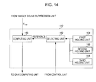
- FIG. 14 is a block diagram of an exemplary functional configuration of a noise correction unit according to the first embodiment of the present invention.
- FIG. 15 is a flowchart of a noise correction process according to the first embodiment of the present invention.
- FIG. 16 is a block diagram of an exemplary functional configuration of a sound processing apparatus according to the first embodiment of the present invention.
- FIG. 17 illustrates the difference between output signals in different formulations
- FIG. 18 is a block diagram of an exemplary functional configuration according to a second embodiment of the present invention.
- FIG. 19 is a diagram illustrating noise spectra before and after target sound is emphasized according to the second embodiment of the present invention.
- FIG. 20 is a diagram illustrating target sound spectra before and after target sound is emphasized according to the second embodiment of the present invention.
- FIG. 21 illustrates a related art
- FIG. 22 illustrates a related art.
- a technique in which noise is suppressed from input sound including the noise in order to emphasize target sound has been developed (refer to, for example, Japanese Patent No. 3677143, Japanese Patent No. 4163294, and Japanese Unexamined Patent Application Publication No. 2009-49998).
- a signal including emphasized target sound hereinafter referred to as a “sound frequency component”
- a signal including the suppressed target sound hereinafter referred to as a “noise frequency component”
- the sound frequency component includes target sound and noise and the noise frequency component includes only the noise. Then, spectral subtraction is performed using the sound frequency component and the noise frequency component. In the spectral subtraction process described in Japanese Patent No. 3677143, particular distortion called musical noise may occur in the processed sound signal, which is problematic. In addition, although it is presumed that noise included in the sound frequency component is the same as noise included in the noise frequency component, the two may not be the same in reality.
- spectral subtraction a noise component included in a signal is estimated, and subtraction is performed on the power spectrum.
- S denote a target sound component included in a sound frequency component X
- N denote a noise component included in the sound frequency component X
- N′ denote the noise frequency component.
- the power spectrum of a processed frequency component Y is expressed as follows:
- 2
- a noise component can be suppressed by multiplying X by a predetermined value (hereinafter referred to as a “gain value”) even when subtraction is used as follows:
- Ws(h) can be considered as a function of the ratio h of X to N′, the curve thereof is shown in FIG. 21 .
- the range h ⁇ 1 is referred to as “flooring”.
- the curve of Ws(h) has a significantly large slope in a range in which h is small.
- the resultant gain value significantly oscillates.
- the frequency component is multiplied by a significantly changing value for each time-frequency representation. In this way, noise called musical noise is generated.
- noise is suppressed by multiplying the sound frequency component by the following value for a target sound component S and a noise component N as follows:
- the curve of W(h) has a large slope in a range in which h is small. Due to output adaptation, the variance of h is small (the values of h are concentrated around a value of 1). Thus, as compared with an existing technique, the variation in the gain value to be multiplied can be kept small. However, it is not desirable that the values of h be concentrated at a point at which the slope is large.
- the sound processing apparatus according to the present embodiment is devised. According to the present embodiment, sound emphasis with reduced musical noise can be performed using a certain gain function.
- a gain function G(r) used for suppressing noise has the following features:
- a graph 300 shown in FIG. 1 indicates the curve of the function G(r) that satisfies the above-described conditions (1) to (4).
- FIG. 2 is a graph of the distribution of the values of h in a period for which only noise is present using actual observation data. As indicated by a histogram 301 , in the actual observation data, almost all values (80%) of h in a period for which only noise is present are concentrated at values 0 to 2. Accordingly, the range in which r is small in the above-described condition (1) can be defined as a range in which 80% of data is included when the histogram of a noise-ratio(h) is computed in a period including only noise. In the following description, noise is suppressed using a gain function G(r) that provides a minimized value and that has a small slope in the range R 1 in which r ⁇ 2.
- the power spectrum in the time direction is averaged by detecting a target sound period. For example, by performing long-term averaging of the power spectrum in a period for which target sound is not present, the variance in the time direction can be decreased. Thus, a value having a small variation can be output in the range R 1 in which r is small using the above-described gain function. In addition, a value having a small variation in the time direction can be obtained. Thus, the musical noise can be reduced.
- the frequency characteristic is corrected so that the ratio of the noise component N included in the sound frequency component to the noise frequency component N′ is within the range R 1 of G(r).
- h can be further decreased when the gain value is computed and, therefore, the variance can be further decreased.
- FIG. 3 is a block diagram of an exemplary functional configuration of the sound processing apparatus 100 .
- the sound processing apparatus 100 includes a target sound emphasizing unit 102 , a target sound suppressing unit 104 , a gain computing unit 106 , a gain multiplier unit 108 , a target sound period detecting unit 110 , and a noise correction unit 112 .
- the target sound emphasizing unit 102 emphasizes target sound included in an input sound including noise.
- the target sound emphasizing unit 102 acquires a sound frequency component Y emp .
- the present invention is not limited to such a case.
- the sound X i may be input from a single microphone.
- the sound frequency component Y emp acquired by the target sound emphasizing unit 102 is supplied to the gain computing unit 106 , the gain multiplier unit 108 , and the target sound period detecting unit 110 .
- the target sound suppressing unit 104 suppresses the target sound in the input sound in which the target sound and noise are included. Thus, the target sound suppressing unit 104 acquires a noise frequency component Y sup . By suppressing the target sound using the target sound suppressing unit 104 , a noise component can be estimated.
- the noise frequency component Y sup acquired by the target sound suppressing unit 104 is supplied to the gain computing unit 106 , the target sound period detecting unit 110 , and the noise correction unit 112 .
- the gain computing unit 106 computes a gain value to be multiplied by the sound frequency component using a certain gain function corresponding to the sound frequency component acquired by the target sound emphasizing unit 102 and the noise frequency component acquired by the target sound suppressing unit 104 .
- the term “certain gain function” refers to a gain function providing a gain value and a slope of the gain function that are smaller than predetermined values when an energy ratio of the sound frequency component to the noise frequency component is smaller than or equal to a predetermined value, as shown in FIG. 1 .
- the gain multiplier unit 108 multiplies the gain value computed by the gain computing unit 106 by the sound frequency component acquired by the target sound emphasizing unit 102 . By multiplying the sound frequency component by the gain value provided by the gain function shown in FIG. 1 , musical noise can be reduced and, therefore, noise can be suppressed.
- the target sound period detecting unit 110 detects a period for which the target sound included in the input sound is present.
- the target sound period detecting unit 110 computes the amplitude spectrum from the sound frequency component Y emp supplied from the target sound emphasizing unit 102 and the amplitude spectrum from the noise frequency spectrum Y sup acquired from the target sound suppressing unit 104 and obtains a correlation between the amplitude spectrum and the input sound X i and a correlation between the amplitude spectrum and the input sound X i . In this way, the target sound period detecting unit 110 detects the period of the target sound.
- a process of detecting the target sound performed by the target sound period detecting unit 110 is described in more detail below.
- the gain computing unit 106 averages the power spectrum of the sound frequency component acquired by the target sound emphasizing unit 102 and the power spectrum acquired by the target sound suppressing unit 104 in accordance with the result of detection performed by the target sound period detecting unit 110 .
- the function of the gain computing unit 106 in accordance with the result of detection performed by the target sound period detecting unit 110 is described next with reference to FIG. 4 .
- the gain computing unit 106 includes a computing unit 122 , a first averaging unit 124 , a first holding unit 126 , a gain computing unit 128 , a second averaging unit 130 , and a second holding unit 132 .
- the computing unit 122 computes the power spectrum for each of the sound frequency component Y emp acquired by the target sound emphasizing unit 102 and the frequency spectrum Y sup acquired by the target sound suppressing unit 104 .
- the first averaging unit 124 averages the power spectrum in accordance with a control signal indicating the target sound period detected by the target sound period detecting unit 110 .
- the first averaging unit 124 averages the power spectrum in accordance with the result of detection performed by the target sound period detecting unit 110 using the first-order attenuation.
- Pn r 3 ⁇ Pn +(1 ⁇ r 3 ) ⁇ Y sup 2
- r 3 be a value close to r 2 .
- r 1 and r 2 may be continuously changed. A technique for continuously changing r 1 and r 2 is described in more detail below.
- the present embodiment is not limited to such an operation. For example, N frames may be averaged, and, like r, the number N may be controlled. That is, if the target sound is present, control may be performed using the average of the past three frames. However, if the target sound is not present, control may be performed using the average of the past seven frames.
- the variance in the time direction can be decreased.
- a value having a small variation can be output in the range in which r is small (R 1 ). That is, by using the gain function G(r), the occurrence of musical noise can be reduced even in the range in which r is small.
- the value having a small variation in the time direction can be obtained. In this way, the musical noise can be further reduced.
- long-term averaging is performed in a period for which a target sound is present, an echo is sensed by a user. Accordingly, the smoothing coefficient r is controlled in accordance with the presence of the target sound.
- the second averaging unit 130 performs a gain value averaging process the same as that performed by the first averaging unit 124 .
- the averaging coefficients may be values that are the same as r 1 , r 2 , and r 3 . Alternatively, the averaging coefficients may be values different from r 1 , r 2 , and r 3 .
- the averaging process performed by the gain computing unit 106 is described next with reference to FIG. 5 .
- FIG. 5 is a flowchart of the averaging process performed by the gain computing unit 106 .
- the gain computing unit 106 acquires the frequency spectra (Y emp , Y sup ) from the target sound emphasizing unit 102 and the target sound suppressing unit 104 (step S 102 ). Thereafter, the gain computing unit 106 computes the power spectra (Y emp 2 , Y sup 2 ) (step S 104 ). Subsequently, the gain computing unit 106 acquires past averaged power spectra (Px, Pn) from the first holding unit 126 (step S 106 ). The gain computing unit 106 determines whether the period is a period for which a target sound is present (step S 108 ).
- step S 120 the gain computing unit 106 transmits the averaged gain value G to the gain multiplier unit 108 (step S 122 ). Thereafter, the gain computing unit 106 stores Px and Pn in the first holding unit 126 (step S 124 ) and stores the gain value G in the second holding unit 132 (step S 126 ).
- This process is performed for all of the frequency ranges.
- the present embodiment is not limited thereto. Different averaging coefficients may be used for averaging of the power spectrum and averaging of the gain.
- the target sound period detecting unit 110 includes a computing unit 131 , a correlation computing unit 134 , a comparing unit 136 , and a determination unit 138 .
- the computing unit 131 receives the sound frequency component Y emp supplied from the target sound emphasizing unit 102 , the frequency spectrum Y sup supplied from the target sound suppressing unit 104 , and one of the frequency spectra X i of the input signal. In order to select one of the frequency spectra X i , any one of the microphones can be selected. However, if the position from which the target sound is input is predetermined, it is desirable that a microphone set at a position closest to the position be used. In this way, the target sound can be input at the highest level.
- the computing unit 131 computes the amplitude spectrum or the power spectrum of each of the input frequency spectra. Thereafter, the correlation computing unit 134 computes a correlation C 1 between the amplitude spectrum of Y emp and the amplitude spectrum of X i and a correlation C 2 between the amplitude spectrum of Y sup and the amplitude spectrum of X.
- the comparing unit 136 compares the correlation C 1 with the correlation C 2 computed by the correlation computing unit 134 .
- the determination unit 138 determines whether the target sound is preset or not in accordance with the result of comparison performed by the comparing unit 136 .
- the determination unit 138 determines whether the target sound is present using the correlation between the amplitude spectra and the following technique.
- the following components are included in the signal input to the computing unit 131 : the sound frequency component Y emp acquired from the target sound emphasizing unit 102 (the sum of the target sound and the suppressed noise component), the frequency spectrum Y sup acquired from the target sound suppressing unit 104 (the noise component), and one of the frequency spectra X i of the input signal (the sum of the target sound and the suppressed noise component).
- the correlation between the amplitude spectra exhibits a large value when the two spectra are similar.
- a graph 310 shown in FIG. 7 in a period for which the target sound is present, the shape of spectrum X i is more similar to Y emp than Y sup .
- a graph 312 shown in FIG. 7 in a period for which the target sound is not present, only noise is present. Therefore, Y sup is similar to Y emp , and the shape of X i is similar to Y sup and Y emp .
- the correlation value C 1 between X i and Y emp is larger than the correlation value C 2 between X i and Y sup in a period for which the target sound is present.
- C 1 is substantially the same as C 2 .
- the value obtained by subtracting the correlation value C 2 from the correlation value C 1 is substantially the same as the value indicating the period for which the actual target sound is present.
- FIG. 9 is a flowchart of the process of detecting a target sound period performed by the target sound period detecting unit 110 .
- the sound frequency component Y emp is acquired from the target sound emphasizing unit 102
- the frequency spectrum Y sup is acquired from the target sound suppressing unit 104
- the frequency spectrum X i is acquired from the input of the microphone (step S 132 ).
- the amplitude spectrum is computed using the frequency spectrum acquired in step S 132 (step S 134 ). Thereafter, the target sound period detecting unit 110 computes the correlation C 1 between the amplitude spectra of X i and Y emp and the correlation C 2 between the amplitude spectra of X i and Y sup (step S 136 ). Subsequently, the target sound period detecting unit 110 determines whether a value obtained by subtracting the correlation C 2 from the correlation C 1 (i.e., C 1 ⁇ C 2 ) is greater than a threshold value Th of X i (step S 138 ).
- step S 138 If, in step S 138 , it is determined that (C 1 ⁇ C 2 ) is greater than Th, the target sound period detecting unit 110 determines that the target sound is present (step S 140 ). However, if, in step S 138 , it is determined that (C 1 ⁇ C 2 ) is less than Th, the target sound period detecting unit 110 determines that the target sound is not present (step S 142 ). As described above, the process of detecting a target sound period is performed by the target sound period detecting unit 110 .
- amplitude spectra are defined as follows:
- a xi (n, k) amplitude spectrum of frame n of X i in frequency bin k
- a emp (n, k) amplitude spectrum of frame n of Y emp in frequency bin k
- a sup (n, k) amplitude spectrum of frame n of Y sup in frequency bin k.
- a whitening process is performed using the average value of Ax i as follows:
- the weight p(k) is represented as a function 316 shown in FIG. 10 .
- high energy is mainly concentrated in a low frequency range.
- the above-mentioned whitening process is described in more detail next with reference to FIG. 11 .
- the amplitude spectrum exhibits only positive values. Therefore, the correlation value also exhibits only positive values. Consequently, the range of the value is small.
- the correlation value ranges between about 0.6 to about 1.0. Accordingly, by subtracting a reference DC component, the amplitude spectrum can be made to be positive or negative. As used herein, such an operation is referred to as “whitening”. By performing whitening in this manner, the correlation value can also range between ⁇ 1 and 1. In this way, the accuracy of detecting the target sound can be increased.
- the smoothing coefficients r 1 and r 2 can be continuously changed.
- C 1 , C 2 , and the threshold value Th computed by the target sound period detecting unit 110 are used.
- ⁇ ,1). where for example, ⁇ 1 or 2, and min represents a function that selects the smaller value from two values of t.
- ⁇ is close to 1 when the target sound is present.
- control is performed so that r ⁇ r 1 if the target sound is present and, otherwise, r ⁇ r 2 .
- the noise correction unit 112 can correct the noise frequency component so that the magnitude of the noise frequency component acquired by the target sound suppressing unit 104 corresponds to the magnitude of the noise component included in the sound frequency component acquired by the target sound emphasizing unit 102 .
- h when the gain value is computed by the gain computing unit 106 , h can be decreased and, thus, the variance can be further decreased.
- the noise can be significantly suppressed, and the musical noise can be significantly reduced.
- the idea for correcting noise performed by the noise correction unit 112 is described first.
- the following process is performed for each of the frequency components. However, for simplicity, description is made without using a frequency index.
- the target sound can be decreased or increased.
- the noise component included in the output of the target sound emphasizing unit 102 differs from the output of the target sound suppressing unit 104 unless W emp is the same as W sup . More specifically, since noise is suppressed in the power spectrum, the levels of noise for the individual frequencies are not the same. Therefore, by correcting W emp and W sup , h used when the gain value is computed can be made close to 1. That is, the gain value can be concentrated at small values and at a point at which the slope of the gain function is small. h can be expressed as follows:
- h can be made to approach 1 from a value greater than 1 by performing the correction.
- the noise suppression amount can be improved.
- h can be made to approach 1 from a value less than 1 by performing the correction.
- the degradation of sound can be made small.
- the noise correction unit 112 includes a computing unit 140 and a holding unit 142 .
- the computing unit 140 receives the frequency spectrum Y sup acquired by the target sound suppressing unit 104 . Thereafter, the computing unit 140 references the holding unit 142 and computes a correction coefficient.
- the computing unit 140 multiplies the input frequency spectrum Y sup by the correction coefficient.
- the computing unit 140 computes a noise spectrum Ycomp.
- the computed noise spectrum Ycomp is supplied to the gain computing unit 106 .
- the holding unit 142 stores the covariance of the noise and coefficients used in the target sound emphasizing unit 102 and the target sound suppressing unit 104 .
- FIG. 13 is a flowchart of the noise correction process performed by the noise correction unit 112 .
- the noise correction unit 112 acquires the frequency spectrum Y sup from the target sound suppressing unit 104 first (step S 142 ). Thereafter, the noise correction unit 112 acquires the covariance, the coefficient for emphasizing the target sound, and the coefficient for suppressing the target sound from the holding unit 142 (step S 144 ). Subsequently, a correction coefficient Gcomp is computed for each of the frequencies (step S 146 ).
- the noise correction unit 112 transmits the resultant value Ycomp computed in step S 148 to the gain computing unit 106 (step S 150 ).
- the above-described process is repeatedly performed by the noise correction unit 112 for each of the frequencies.
- the above-described covariance Rn of the noise can be computed using the following equation (refer to “Measurement of Correlation Coefficients in Reverberant Sound Fields”, Richard K. Cook et. al, THE JOURNAL OF THE ACOUSTICAL SOCIETY OF AMERICA, VOLUME 26, NUMBER 6, November 1955):
- R n ⁇ ( ⁇ ) ( r 11 ⁇ ( ⁇ ) ... r 1 ⁇ M ⁇ ( ⁇ ) ⁇ ... ⁇ r M ⁇ ⁇ 1 ⁇ ( ⁇ ) ... r MM ⁇ ( ⁇ ) )
- r ij ⁇ ( ⁇ ) sin ⁇ ( ⁇ ⁇ d ij / c ) ⁇ ⁇ d ij / c
- d ij distance between microphones i and j
- the following coefficient can be generated using the target sound emphasizing unit 102 , the above-described transfer characteristic A, and the covariance Rn (in general, this technique is referred to as “maximum-likelihood beam forming” (refer to “Adaptive Antenna Technology” (in Japanese), Nobuyoshi KIKUMA, Ohmsha)):
- the technique is not limited to maximum-likelihood beam forming.
- a technique called delayed sum beam forming may be used.
- the delayed sum beam forming is equivalent to the maximum-likelihood beam forming technique if Rn represents a unit matrix.
- the following coefficient is generated using the above-described A and a transfer characteristic other than A:
- the coefficient makes a signal “1” for a direction different from the direction of the target sound and makes the signal “0” for the direction of the target sound.
- the noise correction unit 112 may change the correction coefficient on the basis of a selection signal received from a control unit (not shown).
- the noise correction unit 112 can include a computing unit 150 , a selecting unit 152 , and a plurality of holding units (a first holding unit 154 , a second holding unit 156 , and a third holding unit 158 ). Each of the holding units holds a different correction coefficient.
- the selecting unit 152 acquires one of the correction coefficients held in the first holding unit 154 , the second holding unit 156 , and the third holding unit 158 on the basis of the selection signal supplied from the control unit.
- control unit operates in response to an input from a user or the state of the noise and supplies the selection signal to the selecting unit 152 . Thereafter, the computing unit 150 multiplies the input frequency spectrum Y sup by the correction coefficient selected by the selecting unit 152 . Thus, the computing unit 150 computes the noise spectrum Ycomp.
- the frequency spectrum Y sup is acquired from the target sound suppressing unit 104 (step S 152 ). Thereafter, the selection signal is acquired from the control unit (step S 154 ). Subsequently, it is determined whether the value of the acquired selection signal differs from the current value (step S 156 ).
- step S 162 if, in step S 156 , it is determined that the value of the acquired selection signal is the same as the current value, the process in step S 162 is performed. Thereafter, the computation result Ycomp obtained in step S 162 is transmitted to the gain computing unit 106 (step S 164 ). The above-described process is repeatedly performed by the noise correction unit 112 for each of the frequency ranges.
- a noise correction unit 202 may compute the covariance of noise using the result of detection performed by the target sound period detecting unit 110 .
- the noise correction unit 202 performs noise correction using the sound frequency component Y emp output from the target sound emphasizing unit 102 and the result of detection performed by the target sound period detecting unit 110 in addition to the frequency spectrum Y sup output from the target sound suppressing unit 104 .
- the first exemplary embodiment has such a configuration and features.
- noise can be suppressed using the gain function G(r) having the features shown FIG. 1 . That is, by multiplying the frequency component of the sound by a gain value in accordance with the energy ratio of the frequency component of the sound to the frequency component of noise, the noise can be appropriately suppressed.
- the variance in the time direction can be decreased.
- a value having a small variation in the time direction can be obtained and, therefore, the occurrence of musical noise can be reduced.
- the frequency characteristic is corrected so that the ratio of the noise component N included in the sound frequency component to the noise frequency component N′ is within the range R 1 of G(r). In this way, when the gain value is computed, h can be made small and, therefore, the variance can be further reduced. As a result, the noise can be significantly suppressed, and the musical noise can be significantly reduced.
- the sound processing apparatus 100 or 200 can be used in cell phones, Bluetooth headsets, headsets used in a call center or Web conference, IC recorders, video conference systems, and Web conference and voice chat using a microphone attached to the body of a laptop personal computer (PC).
- PC personal computer
- a second exemplary embodiment is described next.
- the first exemplary embodiment has described a technique for reducing musical noise while significantly suppressing noise using a gain function.
- a technique for significantly simply reducing the musical noise using a plurality of microphones and spectral subtraction (hereinafter also referred to as “SS”) and emphasizing target sound is described.
- SS-based technique the following equations are satisfied:
- FIG. 17 illustrates the difference between the output signals in the above-described formulations in SS.
- a graph 401 shown in FIG. 17 indicates the sound frequency component X output from a microphone.
- a graph 402 indicates the sound frequency component X after G is multiplied in Formulation 1. In this case, although the level can be lowered, the shape of the frequency is not maintained.
- a graph 403 indicates the sound frequency component X after G is multiplied in Formulation 2. In this case, the level is lowered with the shape of the frequency unchanged.
- G 2 1 - ⁇ ⁇ ⁇ N ⁇ 2 ⁇ X ⁇ 2 > G th 2
- the above-described process is realized by setting ⁇ to about 2. However, in general, the process is not effective unless the estimated noise component N is correct.
- a second key point of the present invention is to use a plurality of microphones.
- a noise component adequate for the above-described process can be effectively searched for, and a constant G th can be multiplied.
- An exemplary functional configuration of a sound processing apparatus 400 according to the present embodiment is described next with reference to FIG. 18 .
- the sound processing apparatus 400 includes a target sound emphasizing unit 102 , a target sound suppressing unit 104 , a target sound period detecting unit 110 , a noise correction unit 302 , and a gain computing unit 304 .
- the features different from those of the first exemplary embodiment are described in detail, and descriptions of features similar to those of the first exemplary embodiment are not repeated.
- correction is made so that the power of Y sup is the same as the power of Y emp by using the noise correction unit 112 . That is, the power of noise after the target sound is emphasized is estimated.
- correction is made so that the power of Y sup is the same as the power of X i . That is, the power of noise before the target sound is emphasized is estimated.
- the noise correction unit 302 In order to estimate the noise before the target sound is emphasized, the following value computed by the noise correction unit 302 :
- Gcomp R n ⁇ ( i , i ) W sup H ⁇ R n ⁇ W sup
- R n (i, i) denotes the value of Rn in the i-th row and i-th column.
- the noise component included in the input of a microphone i before the target sound is emphasized can be estimated. Comparison of the actual noise spectrum after the target sound is emphasized and the actual noise spectrum before the target sound is emphasized is shown by a graph 410 in FIG. 19 . As indicated by the graph 410 , the noise before the target sound is emphasized is greater than the noise after the target sound is emphasized. In particular, this is prominent in the low frequency range.
- comparison of the actual noise spectrum after the target sound is emphasized and the target sound spectrum input to the microphone is shown by a graph 412 in FIG. 20 .
- the target sound component is not significantly changed before the target sound is emphasized and after the target sound is emphasized.
- the noise component is multiplied by a constant gain G th .
- the target sound is multiplied by a value close to 1 than G th , although the target sound is slightly degraded. Accordingly, even when the gain function based on SS is used, sound having small musical noise can be acquired. In this way, even when a spectral subtraction based technique is used, musical noise can be simply reduced and sound emphasis can be performed by using the feature of a microphone array process (i.e., by estimating the noise component before the target sound is emphasized and using the noise component).
- the steps performed in the sound processing apparatus 100 , 200 , and 400 are not necessarily performed in the time sequence described in the flowcharts. That is, the steps performed in the sound processing apparatus 100 , 200 , and 400 may be performed concurrently even when the processes in the steps are different.
- a computer program can be produced.
- a storage medium that stores the computer program can be also provided.
Abstract
Description
|Y| 2 =|X| 2 −|N′| 2
Px=r 1 ·Px+(1−r 1)·Y emp 2
Pn=r 3 ·Pn+(1−r 3)·Y sup 2
Px=r 2 ·Px+(1−r 2)·Y emp 2
Pn=r 3 ·Pn+(1−r 3)·Y sup 2
0≦r 1 ≦r 2≦1
G(h)=b·e −c·h
Px=r·Px+(1−r)·Y emp 2
Pn=r 3 ·Pn+(1−r 3)·Y sup 2
G=r·G+(1−r)·g
ν=min(∥C 1 −C 2 |−Th| β,1).
where for example, β=1 or 2, and min represents a function that selects the smaller value from two values of t.
r=ν·r 1+(1−ν)·r 2
Px=r·Px+(1−r)·Y emp 2
X=A·S+N N=(X i ,X 2 , . . . , X M)
A=(a 1 ,a 2 , . . . , a m)T
N=(N 1 ,N 2 , . . . , N M)
where M demotes the number of microphones.
Y emp =W emp H ·X=S+W emp H ·N
Y sup =W sup H·X=W sup H ·N
|W emp H ·N| 2 >|W sup H ·N| 2,
h can be made to approach 1 from a value greater than 1 by performing the correction. Thus, the noise suppression amount can be improved.
|W emp H ·N| 2 <|W sup H ·N| 2,
h can be made to approach 1 from a value less than 1 by performing the correction. Thus, the degradation of sound can be made small.
Y comp=√{square root over (G comp)}·Y sup
γij(ω)=J 0(ω·d ij /c)
X(ω)=N(ω)
r ij(ω)=E└X i(ω)·X j(ω)*┘
where X* denote a complex conjugate number.
Y out=√{square root over (G comp)}·Y sup
is rewritten as the value indicated by the following expression:
where Rn(i, i) denotes the value of Rn in the i-th row and i-th column.
Claims (20)
Applications Claiming Priority (2)
| Application Number | Priority Date | Filing Date | Title |
|---|---|---|---|
| JPP2010-059623 | 2010-03-16 | ||
| JP2010059623A JP5678445B2 (en) | 2010-03-16 | 2010-03-16 | Audio processing apparatus, audio processing method and program |
Publications (2)
| Publication Number | Publication Date |
|---|---|
| US20110228951A1 US20110228951A1 (en) | 2011-09-22 |
| US8861746B2 true US8861746B2 (en) | 2014-10-14 |
Family
ID=44602415
Family Applications (1)
| Application Number | Title | Priority Date | Filing Date |
|---|---|---|---|
| US13/041,638 Expired - Fee Related US8861746B2 (en) | 2010-03-16 | 2011-03-07 | Sound processing apparatus, sound processing method, and program |
Country Status (3)
| Country | Link |
|---|---|
| US (1) | US8861746B2 (en) |
| JP (1) | JP5678445B2 (en) |
| CN (1) | CN102194464A (en) |
Families Citing this family (17)
| Publication number | Priority date | Publication date | Assignee | Title |
|---|---|---|---|---|
| CN101213589B (en) * | 2006-01-12 | 2011-04-27 | 松下电器产业株式会社 | Object sound analysis device, object sound analysis method |
| US8965756B2 (en) * | 2011-03-14 | 2015-02-24 | Adobe Systems Incorporated | Automatic equalization of coloration in speech recordings |
| JP6064370B2 (en) * | 2012-05-29 | 2017-01-25 | 沖電気工業株式会社 | Noise suppression device, method and program |
| EP3190587B1 (en) * | 2012-08-24 | 2018-10-17 | Oticon A/s | Noise estimation for use with noise reduction and echo cancellation in personal communication |
| JP2014085609A (en) * | 2012-10-26 | 2014-05-12 | Sony Corp | Signal processor, signal processing method, and program |
| US9516418B2 (en) | 2013-01-29 | 2016-12-06 | 2236008 Ontario Inc. | Sound field spatial stabilizer |
| US9106196B2 (en) * | 2013-06-20 | 2015-08-11 | 2236008 Ontario Inc. | Sound field spatial stabilizer with echo spectral coherence compensation |
| US9099973B2 (en) * | 2013-06-20 | 2015-08-04 | 2236008 Ontario Inc. | Sound field spatial stabilizer with structured noise compensation |
| US9271100B2 (en) | 2013-06-20 | 2016-02-23 | 2236008 Ontario Inc. | Sound field spatial stabilizer with spectral coherence compensation |
| US10043532B2 (en) | 2014-03-17 | 2018-08-07 | Nec Corporation | Signal processing apparatus, signal processing method, and signal processing program |
| WO2015159731A1 (en) * | 2014-04-16 | 2015-10-22 | ソニー株式会社 | Sound field reproduction apparatus, method and program |
| JP2016042132A (en) * | 2014-08-18 | 2016-03-31 | ソニー株式会社 | Voice processing device, voice processing method, and program |
| CN104242850A (en) * | 2014-09-09 | 2014-12-24 | 联想(北京)有限公司 | Audio signal processing method and electronic device |
| CN107997581A (en) * | 2016-12-23 | 2018-05-08 | 芜湖美的厨卫电器制造有限公司 | Water dispenser and its effluent control device and method |
| US10360892B2 (en) * | 2017-06-07 | 2019-07-23 | Bose Corporation | Spectral optimization of audio masking waveforms |
| CN108831493B (en) * | 2018-05-21 | 2020-11-06 | 北京捷通华声科技股份有限公司 | Audio processing method and device |
| CN111568215B (en) * | 2020-02-28 | 2022-05-13 | 佛山市云米电器科技有限公司 | Water dispenser control method, water dispenser and computer readable storage medium |
Citations (6)
| Publication number | Priority date | Publication date | Assignee | Title |
|---|---|---|---|---|
| US6339758B1 (en) | 1998-07-31 | 2002-01-15 | Kabushiki Kaisha Toshiba | Noise suppress processing apparatus and method |
| US20020138254A1 (en) | 1997-07-18 | 2002-09-26 | Takehiko Isaka | Method and apparatus for processing speech signals |
| US6549630B1 (en) * | 2000-02-04 | 2003-04-15 | Plantronics, Inc. | Signal expander with discrimination between close and distant acoustic source |
| JP3677143B2 (en) | 1997-07-31 | 2005-07-27 | 株式会社東芝 | Audio processing method and apparatus |
| US20080075300A1 (en) * | 2006-09-07 | 2008-03-27 | Kabushiki Kaisha Toshiba | Noise suppressing apparatus |
| JP2009049998A (en) | 2007-08-13 | 2009-03-05 | Harman Becker Automotive Systems Gmbh | Noise reduction by combination of beam-forming and post-filtering |
Family Cites Families (4)
| Publication number | Priority date | Publication date | Assignee | Title |
|---|---|---|---|---|
| JP3204892B2 (en) * | 1995-12-20 | 2001-09-04 | 沖電気工業株式会社 | Background noise canceller |
| JP2005037650A (en) * | 2003-07-14 | 2005-02-10 | Asahi Kasei Corp | Noise reducing apparatus |
| WO2006046293A1 (en) * | 2004-10-28 | 2006-05-04 | Fujitsu Limited | Noise suppressor |
| JP4928376B2 (en) * | 2007-07-18 | 2012-05-09 | 日本電信電話株式会社 | Sound collection device, sound collection method, sound collection program using the method, and recording medium |
-
2010
- 2010-03-16 JP JP2010059623A patent/JP5678445B2/en not_active Expired - Fee Related
-
2011
- 2011-03-07 US US13/041,638 patent/US8861746B2/en not_active Expired - Fee Related
- 2011-03-09 CN CN2011100608719A patent/CN102194464A/en active Pending
Patent Citations (8)
| Publication number | Priority date | Publication date | Assignee | Title |
|---|---|---|---|---|
| US20020138254A1 (en) | 1997-07-18 | 2002-09-26 | Takehiko Isaka | Method and apparatus for processing speech signals |
| JP3677143B2 (en) | 1997-07-31 | 2005-07-27 | 株式会社東芝 | Audio processing method and apparatus |
| US6339758B1 (en) | 1998-07-31 | 2002-01-15 | Kabushiki Kaisha Toshiba | Noise suppress processing apparatus and method |
| JP4163294B2 (en) | 1998-07-31 | 2008-10-08 | 株式会社東芝 | Noise suppression processing apparatus and noise suppression processing method |
| US6549630B1 (en) * | 2000-02-04 | 2003-04-15 | Plantronics, Inc. | Signal expander with discrimination between close and distant acoustic source |
| US20080075300A1 (en) * | 2006-09-07 | 2008-03-27 | Kabushiki Kaisha Toshiba | Noise suppressing apparatus |
| JP2009049998A (en) | 2007-08-13 | 2009-03-05 | Harman Becker Automotive Systems Gmbh | Noise reduction by combination of beam-forming and post-filtering |
| US20090067642A1 (en) | 2007-08-13 | 2009-03-12 | Markus Buck | Noise reduction through spatial selectivity and filtering |
Also Published As
| Publication number | Publication date |
|---|---|
| JP2011191669A (en) | 2011-09-29 |
| JP5678445B2 (en) | 2015-03-04 |
| CN102194464A (en) | 2011-09-21 |
| US20110228951A1 (en) | 2011-09-22 |
Similar Documents
| Publication | Publication Date | Title |
|---|---|---|
| US8861746B2 (en) | Sound processing apparatus, sound processing method, and program | |
| US11081123B2 (en) | Microphone array-based target voice acquisition method and device | |
| US8891785B2 (en) | Processing signals | |
| US8954324B2 (en) | Multiple microphone voice activity detector | |
| JP5197458B2 (en) | Received signal processing apparatus, method and program | |
| US8824693B2 (en) | Processing audio signals | |
| JP5331201B2 (en) | Audio processing | |
| US9042573B2 (en) | Processing signals | |
| CN106068535B (en) | Noise suppressed | |
| US6377637B1 (en) | Sub-band exponential smoothing noise canceling system | |
| US9113241B2 (en) | Noise removing apparatus and noise removing method | |
| US8762139B2 (en) | Noise suppression device | |
| EP2254113A1 (en) | Noise suppression apparatus and program | |
| US20100111324A1 (en) | Systems and Methods for Selectively Switching Between Multiple Microphones | |
| WO2017106454A1 (en) | Suppression of breath in audio signals | |
| US8259961B2 (en) | Audio processing apparatus and program | |
| US10015592B2 (en) | Acoustic signal processing apparatus, method of processing acoustic signal, and storage medium | |
| US9743179B2 (en) | Sound field spatial stabilizer with structured noise compensation | |
| EP3291227B1 (en) | Sound processing device, method of sound processing, sound processing program and storage medium | |
| JP2010156742A (en) | Signal processing device and method thereof | |
| US10978087B2 (en) | Signal processing device, teleconferencing device, and signal processing method | |
| EP2816817B1 (en) | Sound field spatial stabilizer with spectral coherence compensation | |
| JP2017083624A (en) | Noise estimation device, program, and method, and speech processing device |
Legal Events
| Date | Code | Title | Description |
|---|---|---|---|
| AS | Assignment |
Owner name: SONY CORPORATION, JAPAN Free format text: ASSIGNMENT OF ASSIGNORS INTEREST;ASSIGNORS:SEKIYA, TOSHIYUKI;OSAKO, KEIICHI;ABE, MOTOTSUGU;REEL/FRAME:025911/0137 Effective date: 20110208 |
|
| FEPP | Fee payment procedure |
Free format text: PAYOR NUMBER ASSIGNED (ORIGINAL EVENT CODE: ASPN); ENTITY STATUS OF PATENT OWNER: LARGE ENTITY |
|
| STCF | Information on status: patent grant |
Free format text: PATENTED CASE |
|
| MAFP | Maintenance fee payment |
Free format text: PAYMENT OF MAINTENANCE FEE, 4TH YEAR, LARGE ENTITY (ORIGINAL EVENT CODE: M1551) Year of fee payment: 4 |
|
| FEPP | Fee payment procedure |
Free format text: MAINTENANCE FEE REMINDER MAILED (ORIGINAL EVENT CODE: REM.); ENTITY STATUS OF PATENT OWNER: LARGE ENTITY |
|
| LAPS | Lapse for failure to pay maintenance fees |
Free format text: PATENT EXPIRED FOR FAILURE TO PAY MAINTENANCE FEES (ORIGINAL EVENT CODE: EXP.); ENTITY STATUS OF PATENT OWNER: LARGE ENTITY |
|
| STCH | Information on status: patent discontinuation |
Free format text: PATENT EXPIRED DUE TO NONPAYMENT OF MAINTENANCE FEES UNDER 37 CFR 1.362 |
|
| FP | Lapsed due to failure to pay maintenance fee |
Effective date: 20221014 |