US8856360B2 - Automatically identifying dynamic internet protocol addresses - Google Patents
Automatically identifying dynamic internet protocol addresses Download PDFInfo
- Publication number
- US8856360B2 US8856360B2 US11/821,211 US82121107A US8856360B2 US 8856360 B2 US8856360 B2 US 8856360B2 US 82121107 A US82121107 A US 82121107A US 8856360 B2 US8856360 B2 US 8856360B2
- Authority
- US
- United States
- Prior art keywords
- addresses
- address
- dynamic
- candidate
- block
- Prior art date
- Legal status (The legal status is an assumption and is not a legal conclusion. Google has not performed a legal analysis and makes no representation as to the accuracy of the status listed.)
- Active, expires
Links
Images


Classifications
-
- H—ELECTRICITY
- H04—ELECTRIC COMMUNICATION TECHNIQUE
- H04L—TRANSMISSION OF DIGITAL INFORMATION, e.g. TELEGRAPHIC COMMUNICATION
- H04L63/00—Network architectures or network communication protocols for network security
- H04L63/14—Network architectures or network communication protocols for network security for detecting or protecting against malicious traffic
- H04L63/1408—Network architectures or network communication protocols for network security for detecting or protecting against malicious traffic by monitoring network traffic
-
- H04L29/12783—
-
- H—ELECTRICITY
- H04—ELECTRIC COMMUNICATION TECHNIQUE
- H04L—TRANSMISSION OF DIGITAL INFORMATION, e.g. TELEGRAPHIC COMMUNICATION
- H04L61/00—Network arrangements, protocols or services for addressing or naming
- H04L61/35—Network arrangements, protocols or services for addressing or naming involving non-standard use of addresses for implementing network functionalities, e.g. coding subscription information within the address or functional addressing, i.e. assigning an address to a function
Definitions
- IP Internet protocol
- a static IP address is an unchanging IP address that a computer uses every time it connects to a network such as the Internet. With a static IP address, a computer's identity can be easily identified by others; that way, for example, a website, email server, or other type of server connection can be hosted.
- a dynamic IP address is an IP address that is assigned to a computer, usually by a remote server that acts as a dynamic host configuration protocol (DHCP) server. IP addresses assigned using DHCP may change depending on the addresses available in the server set scope.
- DHCP dynamic host configuration protocol
- a conventional dynamic IP list contains a list of dialup IP addresses, and may contain other dynamic IP addresses such as digital subscriber line (DSL) and cable user IP address ranges.
- DSL digital subscriber line
- cable user IP address ranges such as digital subscriber line (DSL) and cable user IP address ranges.
- DSL digital subscriber line
- updating the list of dynamic IP addresses relies on the reporting of system administrators. With Internet topology and IP address assignments changing rapidly, such lists can be expected to contain increasingly obsolete information and omit newly configured dynamic IP addresses.
- a reverse domain name system (rDNS) database is another conventional collection of IP address information.
- Reverse DNS is a process that looks up the host name associated with a given IP address.
- An rDNS record translates an IP address into a host name, which may be used to infer the address properties.
- DNS naming conventions and recent proposals on standardizing DNS name assignment schemes not all domains follow the naming rules. In fact, it is estimated that nearly half of all IP addresses do not have rDNS records.
- Dynamic Internet protocol (IP) addresses may be automatically identified and their dynamics patterns may be analyzed. Multi-user IP address blocks are selected from an input dataset as candidates for further analysis. An entropy score is determined for each IP address in every candidate block, and is used to determine a level of dynamic usage. The aggregated level of dynamic usage of a candidate block may be used to distinguish between a dynamic IP address block and a static IP address block where multiple users may share an IP address. IP addresses with high entropy scores are grouped using signal smoothing techniques and then analyzed. IP addresses that might be associated with large-scale proxy clusters may be filtered. An output may include a list of adjusted IP address blocks and their associated dynamics.
- the outputted information may be used in spam detection and filtering, blacklisting, and other security techniques.
- a host may block the dynamic IP addresses as it is widely observed that dynamic IP addresses are used by zombie spammers to send out purely spam emails.
- FIG. 1 is a flow diagram of an example method of dynamic IP address block identification and analysis
- FIG. 2 is a block diagram of an example identification and analysis system
- FIG. 3 shows an example entry in a user login trace
- FIG. 4 is a flow diagram of an example method of candidate IP address block determination and selection
- FIG. 5 shows an example entry in a routing table
- FIG. 6 shows an example entry in a candidate IP address block table
- FIG. 7 is a flow diagram of an example method of entropy score determination
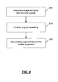
- FIG. 8 is a flow diagram of an example method of identifying IP address blocks based on entropy score
- FIG. 9 is a diagram of example signal pulses representing example normalized sample usage entropies of IP addresses.
- FIG. 10 is a diagram of the example signal pulses of FIG. 9 after being smoothed.
- FIG. 11 is a block diagram of an example computing environment in which example embodiments and aspects may be implemented.
- Dynamic IP addresses may be automatically identified and their dynamics patterns may be analyzed. Dynamic IP addresses correlate well with disruptive network behavior such as email spamming.
- the dynamic IP addresses referred to herein are DHCP addresses, excluding statically configured addresses such as those based on host-MAC (media access control) address mapping or sufficiently long effective lease times so as to be essentially static.
- DHCP addresses excluding statically configured addresses such as those based on host-MAC (media access control) address mapping or sufficiently long effective lease times so as to be essentially static.
- dynamic refers to dynamic address assignment in usage, as opposed to dynamic host configuration protocol.
- Dynamic IP addresses tend to manifest in blocks because it is common for system administrators to assign a range of IP addresses as a pool rather than creating a discrete list of individual IP addresses. Therefore, aggregated IP address usage patterns at the address block level may be identified and used to generate a list of dynamic IP address blocks that are actively in use. A usage-based dynamic IP address map may then be generated.
- block is used to represent a group of continuous IP addresses, and it is a more fine-grained unit than an IP address prefix.
- Dynamic IP addresses are usually allocated from a continuous address range, reachable by the same routing table prefix entries. Meanwhile, users using a dynamic IP address are likely to use other IP addresses from this range as well, due to the nature of dynamic address assignment.
- a history of aggregated user-IP address switching may be used to identify dynamic IP addresses.
- FIG. 1 is a flow diagram of an example method of dynamic IP address block identification and analysis
- FIG. 2 is a block diagram of an example identification and analysis system.
- the example system includes a computing device 200 that has one or more processors 202 , storage 204 (e.g., storage devices, memory, etc.), and software modules 206 .
- the computing device 200 including its processor(s) 202 , storage 204 , and software modules 206 , may be used in the performance of the example methods described herein.
- Example software modules include modules for identifying IP address blocks, calculating usage entropy, and analyzing dynamics, described further herein. While specific functionality is described herein as occurring with respect to specific modules, the functionality may likewise be performed by more, fewer, or other modules. The functionality may be distributed among more than one module.
- An example computing device and its components are described in more detail with respect to FIG. 11 .
- An input dataset 220 such as a user login trace and IP prefix information, is obtained at step 10 and provided to the computing device 200 , in an implementation.
- a user login trace may be obtained from a host or email service 210 , and be based on a period of time.
- the host or email service 210 is shown separate from the computing device 200 , it is contemplated that the host or email service 210 may be in communication with, or otherwise associated with, the computing device 200 . In fact, the host or email service 210 may comprise the computing device 200 .
- Each entry in a user login trace for an email service in an implementation is shown in FIG. 3 .
- Each entry in a user login trace may contain an anonymized user identifier (ID) 70 , the IP address 72 that was used to access the email service, and other aggregated information 74 about the login events corresponding to the user-IP address pair.
- the aggregated information may include the timestamps of the login events over the period of time, and the minimum and the maximum IDs of the operating systems used (the trace collection process encodes each distinct type and version of operating system into a unique operating system ID).
- the examples, techniques, and systems described herein are by no means restricted to user login traces only, and can be applied to any dataset that contains IP addresses and some form of persistent data that can aid the tracking of host identities, e.g., user IDs, cookies, etc.
- host identities e.g., user IDs, cookies, etc.
- Such datasets are readily available in many application logs including, but not limited to, search engine and web server traces.
- the availability of more accurate host identity information e.g., operating system IDs, device fingerprints, packet TTLs (time to live), or MAC addresses
- a historical usage log of a network service that contains not only IP addresses of service requests, but also user login IDs, may be used as input.
- the mapping between IP addresses and users, and vice versa, may be examined, and scanned for specific usage patterns.
- the routing state such as IP address aggregation information, is also provided, via a routing table 230 and described further below. Therefore, the network proximity of the IP addresses used to source these requests may be determined.
- multi-user IP address blocks are determined by the computing device 200 , as candidates for further analysis to determine whether they are dynamic. If more than one user is observed to use the same IP address, it is likely that the IP address has been assigned to more than one host and therefore is a candidate dynamic IP address. However, merely counting the number of users for each individual IP address is not desirable because it is likely that not all the IP addresses in a block will appear in the input dataset, and a small number of individual IP addresses in a dynamic IP block may still appear static by having a single user (e.g., a dynamic IP address assigned to a home router that rarely reboots).
- the IP addresses that are determined to be contained within a dynamic IP address block form a range of addresses.
- the range of addresses are contiguous and do not cross network boundaries.
- Network boundary detection is well known and it is contemplated that conventional techniques may be used to determine network boundaries.
- a set of m continuous IP addresses IP 1 to IP m is selected as a candidate block B(IP 1 , IP m ) if, as shown in the flow diagram of FIG. 4 , the continuous multi-user IP addresses in the block belong to the same autonomous system, and have the same routing prefix entry.
- An example routing table 230 that may be used is a border gateway protocol (BGP) routing table.
- An autonomous system is, in an implementation, a collection of routers under a single administrative authority, and BGP is a standard routing protocol, used primarily for routing between large, heterogenous networks.
- An entry in a routing table in an implementation is shown in FIG. 5 , and comprises an IP prefix 80 and its corresponding origin autonomous system 82 .
- step 700 ensures that IP addresses within the same block are under a single domain and topologically close within a same network boundary.
- IP addresses are divided into ranges using BGP table IP prefix entry information. For each range, both the block size and the gap size are set to 0, at step 705 . The IP addresses are then scanned sequentially in order. It is determined at step 710 whether the current IP address has a user number of two or greater. If so, then the gap is set to 0 at step 712 , and the block size is increased by one at step 714 .
- a gap is defined as a region in the address space with g or more continuous IP addresses that are either not observed in the data or are used by at most a single user, where g is a predetermined number. If the current IP address is determined at step 710 to not have a user number of two or greater, then the gap size is increased by one at step 720 .
- the block does not have significant gaps, as determined at step 730 , in an implementation. By limiting g, it is ensured that a significant portion of the multi-user IP addresses within the block are observed. If the gap size is less than g, then the block size is increased by one at step 714 , and processing continues.
- each IP address block that is determined as a candidate for further analysis has a minimum block size, e.g., by having at least k IP addresses, i.e., m ⁇ k, as determined at step 740 .
- FIG. 6 shows an example entry in a candidate IP address block table, and shows a block ID 90 along with the first IP address 92 and the last IP address 94 in the block. If the block size is k or greater, then the current block is outputted at step 750 and processing continues at step 705 . If the block size is less than k, the current block is not outputted, and processing continues at step 705 . Thus, if the example conditions hold, then the block is determined to be an acceptable candidate IP address block at step 740 , and is outputted at step 750 .
- the parameters k and g have potential impact on both the coverage and the returned IP block sizes.
- a small k is likely to have a large coverage by returning even small dynamic IP ranges, while a large k is more restrictive in considering only large, actively used address blocks.
- a small g tends to break a large address range into small pieces, while a large g is more likely to return large blocks but may potentially result in more false positives (i.e., static IP addresses mistakenly identified as dynamic ones).
- both parameters may be set to 8, which may be a minimum for assigning IP address ranges. It should be noted that by using IP address blocks, IP addresses that are not present in the input data may be included in the output.
- a score is then determined in an implementation, at step 30 , by the computing device 200 .
- the score is an entropy score, also referred to as usage entropy, and is used to determine the level of dynamic usage. As the entropy score increases, the IP address is more likely to be dynamic.
- usage entropy By analyzing the usage entropy, a distinction may be made between a dynamic IP address that had been assigned to multiple hosts (thus multiple users) and a static IP address linked to a single host but shared by multiple users.
- IP addresses Users of dynamic IP addresses can be expected to log in using other IP addresses in the same block. Hence, over a period of time, a dynamic IP address will not only be used by multiple users, but these users also hop around by using other IP addresses in the same block. From a practical viewpoint, dynamic IP addresses are often assigned through random selection from a pool of IP addresses, and when users hop around, the probability of the users using an IP address in the pool can be expected to be roughly uniform.
- an IP address usage entropy computation is performed on a block-by-block basis, as described further with respect to FIG. 7 .
- U denote the set of all users and
- ⁇ m may be constructed at step 800 , with A(i, j) set to 1 if and only if user i has logged into the email server from IP address IP j .
- a metric is used, called IP usage entropy H(j).
- ⁇ m of matrix A may be formed that contains only the rows corresponding to users in U(j). In other words, for a given IP, the submatrix is formed that contains only the rows of users that have used this IP.
- normalized usage entropy H B (j) H ( j )/log 2 m
- H U ( j ) H ( j )/log 2 (
- H B (j) quantifies whether the probability of users U(j) (the set of users that used IP j ) using other IP addresses in the block is uniformly distributed, while H U (j) quantifies the probability skewness only across the set of IP addresses, denoted as C(j), that were actually used by U(j).
- the normalized usage entropy H B (j) of most of the IP addresses in the block is expected to be close to one over time.
- traces are only of limited duration.
- the actual observed set of IP addresses used by U(j), during a trace collection period may only be a fraction of all the IP addresses in the block, especially when the block size is large.
- IP addresses with usage entropies close to one are dynamic IP addresses.
- the dynamic IP addresses manifest as blocks. Therefore, for each multi-user IP address block, it is desirable to identify sub-blocks of IP addresses within each multi-user IP block, such that the usage entropies of a majority of the IP addresses in a sub-block are above a predetermined threshold H e . More particularly, as further described, at step 40 , dynamic IP address blocks are identified by the computing device 200 using signal smoothing techniques, in an implementation, by grouping addresses with high usage entropies, described further with respect to FIG. 8 .
- usage entropy may be regarded as a discrete signal s(i) in the address space, where s(i) can be either H B (i) or H U (i).
- Usage entropies are associated with discrete signals at step 900 .
- FIG. 9 illustrates this representation by plotting the normalized sample usage entropies as signal pulses 95 . Note the time index of the discrete signal is the same as that of the IP address space 96 .
- signal smoothing techniques may then be used, at step 910 , to filter out noises appearing as small dips along the signal.
- the noise may exist because the corresponding IP addresses were either not used by any user or have small usage entropies due to insufficient usage.
- Median filter a well known method for suppressing isolated out-of-range noise, may be used, although it is contemplated that any signal smoothing technique may be used.
- median filter is applied to only those IP addresses with entropies lower than the predetermined threshold H e , in an implementation. Additionally, median filtering is not applied if a signal value does not have a high enough number of neighbors, for boundary condition reasons.
- H e may be set to 0.5 and w may be set to 5.
- the normalized sample usage entropies are well separated in most cases, and so are not very sensitive to thresholding.
- w is set to 5, so that the signal smoothing process can smooth over up to two consecutive dips.
- the multi-user blocks may then be sequentially segmented into smaller segments by discarding the remaining dips after signal smoothing, at step 920 .
- an area under the curve is segmented, with each segment corresponding to a dynamic IP address block.
- the signal smoothing process paves over the sporadic dips in the original signal, but preserves large valleys.
- two dynamic IP address blocks 97 and 98 will be returned.
- IP dynamics analysis and large-scale proxy cluster removal may be performed, by the computing device 200 in an implementation.
- the analysis and removal is directed to the frequency at which a host identity changes with respect to an IP address (i.e., the rate at which an IP address is assigned to different hosts).
- IP address dynamics is a fundamentally challenging task because, for example, this information is very fine grained. Even for IP addresses under the same administrative domain and sharing the same routing prefix, IP address dynamics can be very different. For example, static IP addresses for web servers and email servers may be adjacent to a wireless DHCP IP range. Another reason is because many internet service providers (ISPs) and system administrators often consider IP address dynamics to be confidential and proprietary, since such information can potentially be used to infer the size of customer population and operation status. Additionally, the Internet is composed of a large number of independent domains, each having their own policies for IP address assignments.
- ISPs internet service providers
- a metric to quantify IP address dynamics is IP volatility, which expresses the rate at which a given IP address is assigned to different hosts.
- IP volatility expresses the rate at which a given IP address is assigned to different hosts.
- two metrics may be considered to represent IP volatility for every identified dynamic IP address: (1) the number of distinct service users that have used this address in input data, and (2) the average service inter-user duration, i.e., the time interval between two different users, consecutive in time, using the same IP address.
- the median inter-user duration may be used as opposed to the mean inter-user duration to eliminate outliers.
- these metrics may be used to quantify IP address volatility for each identified dynamic IP address.
- the input data contains timing information pertaining to the time a user connected to a trace server on a per user-IP pair basis.
- a trace may contain the first and last timestamps that a user connected to the service. These two fields may be used to estimate the inter-user duration.
- IP address dynamics analysis in terms of IP volatility estimation may also be used to remove a class of potential false positive IP addresses.
- the first class comprises groups of proxies that employ load balancing to designate users to different servers.
- the second case includes Internet cafes, teaching clusters, and library machines, where a user physically logs in to any one of a group of equivalent machines. Both cases correspond to a cluster of machines that are configured with a range of continuous static IP addresses, where a user may use any one of the machines.
- a difference between these two cases is that, for the first case, multiple users can concurrently access a mail service through a single proxy, while in the second case, requests from different users appear sequentially as users cannot simultaneously log on to the same machine.
- the first class of false positives referred to above may be filtered by removing IP addresses with a large number of concurrent accesses. More specifically, consecutive IP addresses may be discarded that are each associated with a large number of users (e.g., at least about 1000 users) and also exhibit very short inter-user duration (e.g., less than about 5 minutes).
- the parameters may be determined by examining the user population of known proxy IPs (identified through rDNS lookup with the keyword proxy, in an implementation): they correspond to a 5% false negative rate of known proxies.
- a list of IP address blocks identified as dynamic IP address blocks may be outputted, by the computing device 200 in an implementation.
- the output may contain the IP address blocks that were identified as being dynamic, and for each returned address, its volatility information, in terms of the rate at which it is assigned to different hosts.
- the information outputted from step 60 may be used in subsequent spam detection and filtering, phishing site detection, web crawling, blacklisting, and other security techniques, at step 70 , as further described herein.
- a host may block the dynamic IP addresses as it is widely observed that dynamic IP addresses are used by zombie spammers to send out purely spam emails.
- the network-based approaches are grounded on the assumption that IP addresses are generally static and that the fraction of dynamic IP addresses tends to be negligible. However, the number of dynamic IP addresses is very large. Identifying active dynamic IP addresses and understanding their properties is desirable for network-based spam filtering approaches. In other words, determining whether an email server is mapped to a dynamic IP address may be a desirable feature to add to spam filtering systems, as well as to systems that identify phishing sites and detect botnet membership.
- Dynamic IP addresses are identified in terms of IP address blocks, often smaller than IP prefixes, and thus provide more precise information. Because the methods may be fully automated, they can be constantly applied to recent logs to obtain up-to-date information. As described herein, such fine-grained dynamics information can suggest possible host properties behind the IP address, e.g., whether the host is an end user computer, a proxy, or belongs to a kiosk-like shared computer.
- the example techniques can be applied to any dataset that contains IP addresses (e.g., user logs, web server logs, search engine logs) and some form of persistent data that can aid tracking of host identities (e.g., user IDs, cookies).
- IP addresses e.g., user logs, web server logs, search engine logs
- persistent data e.g., user IDs, cookies
- Each domain or server can independently process the collected data, with no need to share information across domains and with no required changes at the client side.
- FIG. 11 shows an exemplary computing environment in which example embodiments and aspects may be implemented.
- the computing system environment is only one example of a suitable computing environment and is not intended to suggest any limitation as to the scope of use or functionality. Neither should the computing environment be interpreted as having any dependency or requirement relating to any one or combination of components illustrated in the exemplary operating environment.
- Numerous other general purpose or special purpose computing system environments or configurations may be used. Examples of well known computing systems, environments, and/or configurations that may be suitable for use include, but are not limited to, personal computers, server computers, handheld or laptop devices, multiprocessor systems, microprocessor-based systems, network PCs, minicomputers, mainframe computers, embedded systems, distributed computing environments that include any of the above systems or devices, and the like.
- Computer-executable instructions such as program modules, being executed by a computer may be used.
- program modules include routines, programs, objects, components, data structures, etc. that perform particular tasks or implement particular abstract data types.
- Distributed computing environments may be used where tasks are performed by remote processing devices that are linked through a communications network or other data transmission medium.
- program modules and other data may be located in both local and remote computer storage media including memory storage devices.
- an exemplary system for implementing aspects described herein includes a computing device, such as computing device 100 .
- computing device 100 typically includes at least one processing unit 102 and memory 104 .
- memory 104 may be volatile (such as RAM), non-volatile (such as ROM, flash memory, etc.), or some combination of the two.
- This most basic configuration is illustrated in FIG. 11 by dashed line 106 .
- Device 100 may have additional features/functionality.
- device 100 may include additional storage (removable and/or non-removable) including, but not limited to, magnetic or optical disks or tape.
- additional storage is illustrated in FIG. 11 by removable storage 108 and non-removable storage 110 .
- Device 100 typically includes a variety of computer readable media.
- Computer readable media can be any available media that can be accessed by device 100 and includes both volatile and non-volatile media, removable and non-removable media.
- Computer storage media includes volatile and non-volatile, removable and non-removable media implemented in any method or technology for storage of information such as computer readable instructions, data structures, program modules or other data.
- Memory 104 , removable storage 108 , and non-removable storage 110 are all examples of computer storage media.
- Computer storage media includes, but is not limited to, RAM, ROM, EEPROM, flash memory or other memory technology, CD-ROM, digital versatile disks (DVD) or other optical storage, magnetic cassettes, magnetic tape, magnetic disk storage or other magnetic storage devices, or any other medium which can be used to store the desired information and which can accessed by device 100 . Any such computer storage media may be part of device 100 .
- Device 100 may also contain communications connection(s) 112 that allow the device to communicate with other devices.
- Communications connection(s) 112 is an example of communication media.
- Communication media typically embodies computer readable instructions, data structures, program modules or other data in a modulated data signal such as a carrier wave or other transport mechanism and includes any information delivery media.
- modulated data signal means a signal that has one or more of its characteristics set or changed in such a manner as to encode information in the signal.
- communication media includes wired media such as a wired network or direct-wired connection, and wireless media such as acoustic, RF, infrared and other wireless media.
- Device 100 may also have input device(s) 114 such as keyboard, mouse, pen, voice input device, touch input device, etc.
- Output device(s) 116 such as a display, speakers, printer, etc. may also be included. All these devices are well known in the art and need not be discussed at length here.
Abstract
Description
H(j)=−(Σ(a k /z j)log2(a k /z j)) (1)
for k=1 to m, where ak is the k-th column sum of submatrix Aj, and zj is the sum of all the entries in submatrix Aj.
H B(j)=H(j)/log2 m (2)
H U(j)=H(j)/log2(|C(j)|) (3)
s′(i)=median{s(i−w/2), . . . , s(i+w/2)} (4)
where w is a parameter of the median filter that determines the neighborhood size.
Claims (20)
Priority Applications (1)
| Application Number | Priority Date | Filing Date | Title |
|---|---|---|---|
| US11/821,211 US8856360B2 (en) | 2007-06-22 | 2007-06-22 | Automatically identifying dynamic internet protocol addresses |
Applications Claiming Priority (1)
| Application Number | Priority Date | Filing Date | Title |
|---|---|---|---|
| US11/821,211 US8856360B2 (en) | 2007-06-22 | 2007-06-22 | Automatically identifying dynamic internet protocol addresses |
Publications (2)
| Publication Number | Publication Date |
|---|---|
| US20080320119A1 US20080320119A1 (en) | 2008-12-25 |
| US8856360B2 true US8856360B2 (en) | 2014-10-07 |
Family
ID=40137652
Family Applications (1)
| Application Number | Title | Priority Date | Filing Date |
|---|---|---|---|
| US11/821,211 Active 2030-07-04 US8856360B2 (en) | 2007-06-22 | 2007-06-22 | Automatically identifying dynamic internet protocol addresses |
Country Status (1)
| Country | Link |
|---|---|
| US (1) | US8856360B2 (en) |
Cited By (5)
| Publication number | Priority date | Publication date | Assignee | Title |
|---|---|---|---|---|
| US20130275566A1 (en) * | 2010-12-17 | 2013-10-17 | Hans-Peter Huth | Method for Configuring One or More Devices in an Ethernet-Based Communication Network |
| US10305840B2 (en) * | 2017-06-16 | 2019-05-28 | International Business Machines Corporation | Mail bot and mailing list detection |
| US11218440B2 (en) | 2019-04-30 | 2022-01-04 | Hewlett Packard Enterprise Development Lp | Contiguous subnet IP address allocation |
| US11405355B2 (en) * | 2018-07-12 | 2022-08-02 | Nippon Telegraph And Telephone Corporation | Identification device, identification method, and identification program |
| US20230179567A1 (en) * | 2021-12-07 | 2023-06-08 | Arris Enterprises Llc | Dhcp server ip address allocation improvement to nullify the impact of mac randomization |
Families Citing this family (33)
| Publication number | Priority date | Publication date | Assignee | Title |
|---|---|---|---|---|
| US7761558B1 (en) * | 2006-06-30 | 2010-07-20 | Google Inc. | Determining a number of users behind a set of one or more internet protocol (IP) addresses |
| US10115124B1 (en) * | 2007-10-01 | 2018-10-30 | Google Llc | Systems and methods for preserving privacy |
| US7849146B2 (en) * | 2008-02-21 | 2010-12-07 | Yahoo! Inc. | Identifying IP addresses for spammers |
| US8789171B2 (en) * | 2008-03-26 | 2014-07-22 | Microsoft Corporation | Mining user behavior data for IP address space intelligence |
| US20100031319A1 (en) * | 2008-08-04 | 2010-02-04 | Postalguard Ltd. | Secure messaging using caller identification |
| US8826450B2 (en) * | 2008-09-19 | 2014-09-02 | Yahoo! Inc. | Detecting bulk fraudulent registration of email accounts |
| US7945667B2 (en) * | 2008-12-18 | 2011-05-17 | At&T Intellectual Property I, L.P. | Method and apparatus for inferring the presence of static internet protocol address allocations |
| US9129293B2 (en) | 2009-01-29 | 2015-09-08 | The Nielsen Company (Us), Llc | Methods and apparatus to measure market statistics |
| US8280996B2 (en) * | 2009-01-29 | 2012-10-02 | The Nielsen Company (Us), Llc | Methods and apparatus to collect broadband market data |
| US20100235915A1 (en) * | 2009-03-12 | 2010-09-16 | Nasir Memon | Using host symptoms, host roles, and/or host reputation for detection of host infection |
| US8412847B2 (en) * | 2009-11-02 | 2013-04-02 | Demandbase, Inc. | Mapping network addresses to organizations |
| US9098459B2 (en) * | 2010-01-29 | 2015-08-04 | Microsoft Technology Licensing, Llc | Activity filtering based on trust ratings of network |
| US8370902B2 (en) * | 2010-01-29 | 2013-02-05 | Microsoft Corporation | Rescuing trusted nodes from filtering of untrusted network entities |
| US20110208714A1 (en) * | 2010-02-19 | 2011-08-25 | c/o Microsoft Corporation | Large scale search bot detection |
| US8639773B2 (en) | 2010-06-17 | 2014-01-28 | Microsoft Corporation | Discrepancy detection for web crawling |
| US9148432B2 (en) * | 2010-10-12 | 2015-09-29 | Microsoft Technology Licensing, Llc | Range weighted internet protocol address blacklist |
| US10049377B1 (en) * | 2011-06-29 | 2018-08-14 | Google Llc | Inferring interactions with advertisers |
| US9442881B1 (en) | 2011-08-31 | 2016-09-13 | Yahoo! Inc. | Anti-spam transient entity classification |
| US10037543B2 (en) * | 2012-08-13 | 2018-07-31 | Amobee, Inc. | Estimating conversion rate in display advertising from past performance data |
| US9197657B2 (en) | 2012-09-27 | 2015-11-24 | Hewlett-Packard Development Company, L.P. | Internet protocol address distribution summary |
| US9313169B2 (en) * | 2013-03-14 | 2016-04-12 | Google Inc. | Providing content to devices in a cluster |
| US9729500B2 (en) | 2013-03-15 | 2017-08-08 | Google Inc. | IP allocation pools |
| US9060020B2 (en) * | 2013-04-01 | 2015-06-16 | Arbor Networks, Inc. | Adjusting DDoS protection based on traffic type |
| US9065833B2 (en) | 2013-07-10 | 2015-06-23 | Microsoft Technology Licensing, Llc | Outbound IP address reputation control and repair |
| US9455989B2 (en) * | 2013-07-10 | 2016-09-27 | Microsoft Technology Licensing, Llc | Automatic isolation and detection of outbound spam |
| EP3172889A1 (en) * | 2014-07-25 | 2017-05-31 | Thomson Licensing | Method for modifying a portmap of a cpe device, respective cpe device and computer program |
| US10083464B1 (en) | 2015-04-27 | 2018-09-25 | Google Llc | System and method of detection and recording of realization actions in association with content rendering |
| US10944639B2 (en) * | 2016-06-09 | 2021-03-09 | Akamai Technologies, Inc. | Internet address structure analysis, and applications thereof |
| US9781160B1 (en) * | 2017-05-31 | 2017-10-03 | KnowBe4, Inc. | Systems and methods for discovering suspect bot IP addresses and using validated bot IP address to ignore actions in a simulated phishing environment |
| US11095495B2 (en) * | 2019-04-05 | 2021-08-17 | Arista Networks, Inc. | Multi-result lookups |
| CN110572402B (en) * | 2019-09-11 | 2021-11-16 | 国网湖南省电力有限公司 | Internet hosting website detection method and system based on network access behavior analysis and readable storage medium |
| US11677783B2 (en) * | 2019-10-25 | 2023-06-13 | Target Brands, Inc. | Analysis of potentially malicious emails |
| US20230179579A1 (en) * | 2021-11-18 | 2023-06-08 | Cisco Technology, Inc. | Randomizing server-side addresses |
Citations (23)
| Publication number | Priority date | Publication date | Assignee | Title |
|---|---|---|---|---|
| US5724510A (en) | 1996-09-06 | 1998-03-03 | Fluke Corporation | Method of configuring a valid IP address and detecting duplicate IP addresses in a local area network |
| US5818964A (en) * | 1994-12-27 | 1998-10-06 | Texas Instruments Incorporated | Method and apparatus for selecting an adaptive filter for image data |
| US6212563B1 (en) * | 1998-10-01 | 2001-04-03 | 3Com Corporation | Method and system for setting and managing externally provided internet protocol addresses using the dynamic host configuration protocol |
| US6327621B1 (en) * | 1998-08-25 | 2001-12-04 | International Business Machines Corporation | Method for shared multicast interface in a multi-partition environment |
| US6434600B2 (en) | 1998-09-15 | 2002-08-13 | Microsoft Corporation | Methods and systems for securely delivering electronic mail to hosts having dynamic IP addresses |
| US20020133578A1 (en) | 2001-01-18 | 2002-09-19 | Wu C. T. | Novel method in serving residential broadband subscribers |
| US20030069933A1 (en) | 2001-10-06 | 2003-04-10 | Sung-Yeop Lim | Electronic mail service system and method that make use of dynamic IP filtering technology |
| EP1355448A2 (en) | 2002-04-19 | 2003-10-22 | Nokia Corporation | System and method for providing network configuration information or additional information to wireless terminals |
| US20050022031A1 (en) | 2003-06-04 | 2005-01-27 | Microsoft Corporation | Advanced URL and IP features |
| US6862286B1 (en) * | 2000-05-08 | 2005-03-01 | 3Com Corporation | Tracking dynamic addresses on a network |
| US20050089048A1 (en) * | 2003-10-23 | 2005-04-28 | Bruce Chittenden | Systems and methods for network user resolution |
| US6952735B1 (en) * | 1999-09-01 | 2005-10-04 | Telefonaktiebolaget Lm Ericsson (Publ) | Dynamically distributed IP-pool in GPRS |
| US20060026246A1 (en) * | 2004-07-08 | 2006-02-02 | Fukuhara Keith T | System and method for authorizing delivery of E-mail and reducing spam |
| US20060028996A1 (en) * | 2004-08-09 | 2006-02-09 | Huegen Craig A | Arrangement for tracking IP address usage based on authenticated link identifier |
| US20060133354A1 (en) | 2004-12-20 | 2006-06-22 | Jin-Suk Lee | Apparatus and method for automatically updating address book in an SIP-based VoIP terminal |
| US20060168041A1 (en) * | 2005-01-07 | 2006-07-27 | Microsoft Corporation | Using IP address and domain for email spam filtering |
| WO2006088947A2 (en) | 2005-02-15 | 2006-08-24 | Nphase, Llc | Methods and apparatus for machine-to-machine communications |
| US20060195610A1 (en) * | 2005-02-28 | 2006-08-31 | Sytex, Inc. | Security Enhanced Methods And System For IP Address Allocation |
| US20060248229A1 (en) | 2005-04-27 | 2006-11-02 | 3Com Corporation | Network including snooping |
| US20070250644A1 (en) * | 2004-05-25 | 2007-10-25 | Lund Peter K | Electronic Message Source Reputation Information System |
| US20070250608A1 (en) * | 2001-11-08 | 2007-10-25 | Watt Charles T | System and method for dynamic server allocation and provisioning |
| US20080082658A1 (en) * | 2006-09-29 | 2008-04-03 | Wan-Yen Hsu | Spam control systems and methods |
| US7761558B1 (en) * | 2006-06-30 | 2010-07-20 | Google Inc. | Determining a number of users behind a set of one or more internet protocol (IP) addresses |
Family Cites Families (4)
| Publication number | Priority date | Publication date | Assignee | Title |
|---|---|---|---|---|
| US6003075A (en) * | 1997-07-07 | 1999-12-14 | International Business Machines Corporation | Enqueuing a configuration change in a network cluster and restore a prior configuration in a back up storage in reverse sequence ordered |
| US6173420B1 (en) * | 1997-10-31 | 2001-01-09 | Oracle Corporation | Method and apparatus for fail safe configuration |
| US7085824B2 (en) * | 2001-02-23 | 2006-08-01 | Power Measurement Ltd. | Systems for in the field configuration of intelligent electronic devices |
| US6928579B2 (en) * | 2001-06-27 | 2005-08-09 | Nokia Corporation | Crash recovery system |
-
2007
- 2007-06-22 US US11/821,211 patent/US8856360B2/en active Active
Patent Citations (24)
| Publication number | Priority date | Publication date | Assignee | Title |
|---|---|---|---|---|
| US5818964A (en) * | 1994-12-27 | 1998-10-06 | Texas Instruments Incorporated | Method and apparatus for selecting an adaptive filter for image data |
| US5724510A (en) | 1996-09-06 | 1998-03-03 | Fluke Corporation | Method of configuring a valid IP address and detecting duplicate IP addresses in a local area network |
| US6327621B1 (en) * | 1998-08-25 | 2001-12-04 | International Business Machines Corporation | Method for shared multicast interface in a multi-partition environment |
| US6434600B2 (en) | 1998-09-15 | 2002-08-13 | Microsoft Corporation | Methods and systems for securely delivering electronic mail to hosts having dynamic IP addresses |
| US6212563B1 (en) * | 1998-10-01 | 2001-04-03 | 3Com Corporation | Method and system for setting and managing externally provided internet protocol addresses using the dynamic host configuration protocol |
| US6952735B1 (en) * | 1999-09-01 | 2005-10-04 | Telefonaktiebolaget Lm Ericsson (Publ) | Dynamically distributed IP-pool in GPRS |
| US6862286B1 (en) * | 2000-05-08 | 2005-03-01 | 3Com Corporation | Tracking dynamic addresses on a network |
| US20020133578A1 (en) | 2001-01-18 | 2002-09-19 | Wu C. T. | Novel method in serving residential broadband subscribers |
| US20030069933A1 (en) | 2001-10-06 | 2003-04-10 | Sung-Yeop Lim | Electronic mail service system and method that make use of dynamic IP filtering technology |
| US20070250608A1 (en) * | 2001-11-08 | 2007-10-25 | Watt Charles T | System and method for dynamic server allocation and provisioning |
| EP1355448A2 (en) | 2002-04-19 | 2003-10-22 | Nokia Corporation | System and method for providing network configuration information or additional information to wireless terminals |
| US20050022031A1 (en) | 2003-06-04 | 2005-01-27 | Microsoft Corporation | Advanced URL and IP features |
| US7272853B2 (en) * | 2003-06-04 | 2007-09-18 | Microsoft Corporation | Origination/destination features and lists for spam prevention |
| US20050089048A1 (en) * | 2003-10-23 | 2005-04-28 | Bruce Chittenden | Systems and methods for network user resolution |
| US20070250644A1 (en) * | 2004-05-25 | 2007-10-25 | Lund Peter K | Electronic Message Source Reputation Information System |
| US20060026246A1 (en) * | 2004-07-08 | 2006-02-02 | Fukuhara Keith T | System and method for authorizing delivery of E-mail and reducing spam |
| US20060028996A1 (en) * | 2004-08-09 | 2006-02-09 | Huegen Craig A | Arrangement for tracking IP address usage based on authenticated link identifier |
| US20060133354A1 (en) | 2004-12-20 | 2006-06-22 | Jin-Suk Lee | Apparatus and method for automatically updating address book in an SIP-based VoIP terminal |
| US20060168041A1 (en) * | 2005-01-07 | 2006-07-27 | Microsoft Corporation | Using IP address and domain for email spam filtering |
| WO2006088947A2 (en) | 2005-02-15 | 2006-08-24 | Nphase, Llc | Methods and apparatus for machine-to-machine communications |
| US20060195610A1 (en) * | 2005-02-28 | 2006-08-31 | Sytex, Inc. | Security Enhanced Methods And System For IP Address Allocation |
| US20060248229A1 (en) | 2005-04-27 | 2006-11-02 | 3Com Corporation | Network including snooping |
| US7761558B1 (en) * | 2006-06-30 | 2010-07-20 | Google Inc. | Determining a number of users behind a set of one or more internet protocol (IP) addresses |
| US20080082658A1 (en) * | 2006-09-29 | 2008-04-03 | Wan-Yen Hsu | Spam control systems and methods |
Non-Patent Citations (5)
| Title |
|---|
| "IPsynchro (zip)", http://software.techrepublic.com.com/download.aspx?docid=216065. |
| A. Ramachandran, D. Dagon, and N. Feamster. Can DNSBased Blacklists Keep Up with Bots? In Conference on Email and Anti-Spam, 2006. |
| B. Krishnamurthy and J. Wang. On Network-Aware Clustering of Web Clients. In Proc. of Sigcomm, 2000. |
| Durst, et al., "Testing and Evaluating Computer Intrusion Detection Systems", Date: Jul. 1999, vol. 42, Issue: 7, pp. 53-61, ACM Press, New York, USA. |
| F. Li and M.-H. Hsieh. An Empirical Study of Clustering Behavior of Spammers and Group-based Anti-Spam Strategies. In Conference on Email and Anti-Spam, 2006. |
Cited By (9)
| Publication number | Priority date | Publication date | Assignee | Title |
|---|---|---|---|---|
| US20130275566A1 (en) * | 2010-12-17 | 2013-10-17 | Hans-Peter Huth | Method for Configuring One or More Devices in an Ethernet-Based Communication Network |
| US9935821B2 (en) * | 2010-12-17 | 2018-04-03 | Siemens Aktiengesellschaft | Method for configuring one or more devices in an ethernet-based communication network |
| US10305840B2 (en) * | 2017-06-16 | 2019-05-28 | International Business Machines Corporation | Mail bot and mailing list detection |
| US10862845B2 (en) | 2017-06-16 | 2020-12-08 | Hcl Technologies Limited | Mail bot and mailing list detection |
| US11362982B2 (en) | 2017-06-16 | 2022-06-14 | Hcl Technologies Limited | Mail bot and mailing list detection |
| US11405355B2 (en) * | 2018-07-12 | 2022-08-02 | Nippon Telegraph And Telephone Corporation | Identification device, identification method, and identification program |
| US11218440B2 (en) | 2019-04-30 | 2022-01-04 | Hewlett Packard Enterprise Development Lp | Contiguous subnet IP address allocation |
| US20230179567A1 (en) * | 2021-12-07 | 2023-06-08 | Arris Enterprises Llc | Dhcp server ip address allocation improvement to nullify the impact of mac randomization |
| US11765128B2 (en) * | 2021-12-07 | 2023-09-19 | Arris Enterprises Llc | DHCP server IP address allocation improvement to nullify the impact of mac randomization |
Also Published As
| Publication number | Publication date |
|---|---|
| US20080320119A1 (en) | 2008-12-25 |
Similar Documents
| Publication | Publication Date | Title |
|---|---|---|
| US8856360B2 (en) | Automatically identifying dynamic internet protocol addresses | |
| US10740363B2 (en) | Domain classification based on domain name system (DNS) traffic | |
| US10848401B2 (en) | System and method of identifying internet-facing assets | |
| JP6510040B2 (en) | System and method for identifying suspicious host names | |
| US10742591B2 (en) | System for domain reputation scoring | |
| Lever et al. | A lustrum of malware network communication: Evolution and insights | |
| US10027665B2 (en) | Method and system for tracking machines on a network using fuzzy guid technology | |
| Antonakakis et al. | Building a dynamic reputation system for {DNS} | |
| EP3092569B1 (en) | Cyber security adaptive analytics threat monitoring system and method | |
| US8260914B1 (en) | Detecting DNS fast-flux anomalies | |
| Jiang et al. | Identifying suspicious activities through dns failure graph analysis | |
| WO2018176874A1 (en) | Dns evaluation method and apparatus | |
| CN114846462A (en) | Asset search discovery system using graph data structure | |
| WO2018163464A1 (en) | Attack countermeasure determination device, attack countermeasure determination method, and attack countermeasure determination program | |
| Da Luz | Botnet detection using passive DNS | |
| US11588678B2 (en) | Generating incident response action recommendations using anonymized action implementation data | |
| Wickramasinghe et al. | Uncovering ip address hosting types behind malicious websites | |
| Venkataraman et al. | Automatically inferring the evolution of malicious activity on the internet | |
| Dolberg et al. | Multi-dimensional aggregation for dns monitoring | |
| Fejrskov et al. | Detecting DNS hijacking by using NetFlow data | |
| Yoshida et al. | Cardinality analysis to classify malicious domain names | |
| US20210240791A1 (en) | Ranking services and top n rank lists | |
| Davanian | Effective granularity in internet badhood detection: Detection rate, precision and implementation performance | |
| Moura et al. | of deliverable: Documentation of botnet metrics methodology | |
| Antonakakis | Improving Internet security via large-scale passive and active DNS monitoring |
Legal Events
| Date | Code | Title | Description |
|---|---|---|---|
| AS | Assignment |
Owner name: MICROSOFT CORPORATION, WASHINGTON Free format text: ASSIGNMENT OF ASSIGNORS INTEREST;ASSIGNORS:ACHAN, KANNAN;GILLUM, ELIOT;XIE, YINGLIAN;AND OTHERS;REEL/FRAME:020237/0368 Effective date: 20070621 |
|
| STCF | Information on status: patent grant |
Free format text: PATENTED CASE |
|
| AS | Assignment |
Owner name: MICROSOFT TECHNOLOGY LICENSING, LLC, WASHINGTON Free format text: ASSIGNMENT OF ASSIGNORS INTEREST;ASSIGNOR:MICROSOFT CORPORATION;REEL/FRAME:034542/0001 Effective date: 20141014 |
|
| MAFP | Maintenance fee payment |
Free format text: PAYMENT OF MAINTENANCE FEE, 4TH YEAR, LARGE ENTITY (ORIGINAL EVENT CODE: M1551) Year of fee payment: 4 |
|
| MAFP | Maintenance fee payment |
Free format text: PAYMENT OF MAINTENANCE FEE, 8TH YEAR, LARGE ENTITY (ORIGINAL EVENT CODE: M1552); ENTITY STATUS OF PATENT OWNER: LARGE ENTITY Year of fee payment: 8 |