US8852794B2 - Electric vehicle battery case - Google Patents
Electric vehicle battery case Download PDFInfo
- Publication number
- US8852794B2 US8852794B2 US13/353,060 US201213353060A US8852794B2 US 8852794 B2 US8852794 B2 US 8852794B2 US 201213353060 A US201213353060 A US 201213353060A US 8852794 B2 US8852794 B2 US 8852794B2
- Authority
- US
- United States
- Prior art keywords
- vehicle
- cavity
- housing
- batteries
- battery case
- Prior art date
- Legal status (The legal status is an assumption and is not a legal conclusion. Google has not performed a legal analysis and makes no representation as to the accuracy of the status listed.)
- Active, expires
Links
Images


Classifications
-
- B—PERFORMING OPERATIONS; TRANSPORTING
- B60—VEHICLES IN GENERAL
- B60K—ARRANGEMENT OR MOUNTING OF PROPULSION UNITS OR OF TRANSMISSIONS IN VEHICLES; ARRANGEMENT OR MOUNTING OF PLURAL DIVERSE PRIME-MOVERS IN VEHICLES; AUXILIARY DRIVES FOR VEHICLES; INSTRUMENTATION OR DASHBOARDS FOR VEHICLES; ARRANGEMENTS IN CONNECTION WITH COOLING, AIR INTAKE, GAS EXHAUST OR FUEL SUPPLY OF PROPULSION UNITS IN VEHICLES
- B60K1/00—Arrangement or mounting of electrical propulsion units
- B60K1/04—Arrangement or mounting of electrical propulsion units of the electric storage means for propulsion
-
- H01M2/1083—
-
- B—PERFORMING OPERATIONS; TRANSPORTING
- B60—VEHICLES IN GENERAL
- B60L—PROPULSION OF ELECTRICALLY-PROPELLED VEHICLES; SUPPLYING ELECTRIC POWER FOR AUXILIARY EQUIPMENT OF ELECTRICALLY-PROPELLED VEHICLES; ELECTRODYNAMIC BRAKE SYSTEMS FOR VEHICLES IN GENERAL; MAGNETIC SUSPENSION OR LEVITATION FOR VEHICLES; MONITORING OPERATING VARIABLES OF ELECTRICALLY-PROPELLED VEHICLES; ELECTRIC SAFETY DEVICES FOR ELECTRICALLY-PROPELLED VEHICLES
- B60L50/00—Electric propulsion with power supplied within the vehicle
- B60L50/50—Electric propulsion with power supplied within the vehicle using propulsion power supplied by batteries or fuel cells
- B60L50/60—Electric propulsion with power supplied within the vehicle using propulsion power supplied by batteries or fuel cells using power supplied by batteries
- B60L50/64—Constructional details of batteries specially adapted for electric vehicles
-
- B—PERFORMING OPERATIONS; TRANSPORTING
- B60—VEHICLES IN GENERAL
- B60L—PROPULSION OF ELECTRICALLY-PROPELLED VEHICLES; SUPPLYING ELECTRIC POWER FOR AUXILIARY EQUIPMENT OF ELECTRICALLY-PROPELLED VEHICLES; ELECTRODYNAMIC BRAKE SYSTEMS FOR VEHICLES IN GENERAL; MAGNETIC SUSPENSION OR LEVITATION FOR VEHICLES; MONITORING OPERATING VARIABLES OF ELECTRICALLY-PROPELLED VEHICLES; ELECTRIC SAFETY DEVICES FOR ELECTRICALLY-PROPELLED VEHICLES
- B60L50/00—Electric propulsion with power supplied within the vehicle
- B60L50/50—Electric propulsion with power supplied within the vehicle using propulsion power supplied by batteries or fuel cells
- B60L50/60—Electric propulsion with power supplied within the vehicle using propulsion power supplied by batteries or fuel cells using power supplied by batteries
- B60L50/66—Arrangements of batteries
-
- B—PERFORMING OPERATIONS; TRANSPORTING
- B60—VEHICLES IN GENERAL
- B60L—PROPULSION OF ELECTRICALLY-PROPELLED VEHICLES; SUPPLYING ELECTRIC POWER FOR AUXILIARY EQUIPMENT OF ELECTRICALLY-PROPELLED VEHICLES; ELECTRODYNAMIC BRAKE SYSTEMS FOR VEHICLES IN GENERAL; MAGNETIC SUSPENSION OR LEVITATION FOR VEHICLES; MONITORING OPERATING VARIABLES OF ELECTRICALLY-PROPELLED VEHICLES; ELECTRIC SAFETY DEVICES FOR ELECTRICALLY-PROPELLED VEHICLES
- B60L53/00—Methods of charging batteries, specially adapted for electric vehicles; Charging stations or on-board charging equipment therefor; Exchange of energy storage elements in electric vehicles
- B60L53/10—Methods of charging batteries, specially adapted for electric vehicles; Charging stations or on-board charging equipment therefor; Exchange of energy storage elements in electric vehicles characterised by the energy transfer between the charging station and the vehicle
- B60L53/14—Conductive energy transfer
-
- B—PERFORMING OPERATIONS; TRANSPORTING
- B60—VEHICLES IN GENERAL
- B60L—PROPULSION OF ELECTRICALLY-PROPELLED VEHICLES; SUPPLYING ELECTRIC POWER FOR AUXILIARY EQUIPMENT OF ELECTRICALLY-PROPELLED VEHICLES; ELECTRODYNAMIC BRAKE SYSTEMS FOR VEHICLES IN GENERAL; MAGNETIC SUSPENSION OR LEVITATION FOR VEHICLES; MONITORING OPERATING VARIABLES OF ELECTRICALLY-PROPELLED VEHICLES; ELECTRIC SAFETY DEVICES FOR ELECTRICALLY-PROPELLED VEHICLES
- B60L53/00—Methods of charging batteries, specially adapted for electric vehicles; Charging stations or on-board charging equipment therefor; Exchange of energy storage elements in electric vehicles
- B60L53/80—Exchanging energy storage elements, e.g. removable batteries
-
- B—PERFORMING OPERATIONS; TRANSPORTING
- B60—VEHICLES IN GENERAL
- B60L—PROPULSION OF ELECTRICALLY-PROPELLED VEHICLES; SUPPLYING ELECTRIC POWER FOR AUXILIARY EQUIPMENT OF ELECTRICALLY-PROPELLED VEHICLES; ELECTRODYNAMIC BRAKE SYSTEMS FOR VEHICLES IN GENERAL; MAGNETIC SUSPENSION OR LEVITATION FOR VEHICLES; MONITORING OPERATING VARIABLES OF ELECTRICALLY-PROPELLED VEHICLES; ELECTRIC SAFETY DEVICES FOR ELECTRICALLY-PROPELLED VEHICLES
- B60L58/00—Methods or circuit arrangements for monitoring or controlling batteries or fuel cells, specially adapted for electric vehicles
- B60L58/10—Methods or circuit arrangements for monitoring or controlling batteries or fuel cells, specially adapted for electric vehicles for monitoring or controlling batteries
- B60L58/24—Methods or circuit arrangements for monitoring or controlling batteries or fuel cells, specially adapted for electric vehicles for monitoring or controlling batteries for controlling the temperature of batteries
- B60L58/26—Methods or circuit arrangements for monitoring or controlling batteries or fuel cells, specially adapted for electric vehicles for monitoring or controlling batteries for controlling the temperature of batteries by cooling
-
- H—ELECTRICITY
- H01—ELECTRIC ELEMENTS
- H01M—PROCESSES OR MEANS, e.g. BATTERIES, FOR THE DIRECT CONVERSION OF CHEMICAL ENERGY INTO ELECTRICAL ENERGY
- H01M50/00—Constructional details or processes of manufacture of the non-active parts of electrochemical cells other than fuel cells, e.g. hybrid cells
- H01M50/20—Mountings; Secondary casings or frames; Racks, modules or packs; Suspension devices; Shock absorbers; Transport or carrying devices; Holders
- H01M50/204—Racks, modules or packs for multiple batteries or multiple cells
-
- H—ELECTRICITY
- H01—ELECTRIC ELEMENTS
- H01M—PROCESSES OR MEANS, e.g. BATTERIES, FOR THE DIRECT CONVERSION OF CHEMICAL ENERGY INTO ELECTRICAL ENERGY
- H01M50/00—Constructional details or processes of manufacture of the non-active parts of electrochemical cells other than fuel cells, e.g. hybrid cells
- H01M50/20—Mountings; Secondary casings or frames; Racks, modules or packs; Suspension devices; Shock absorbers; Transport or carrying devices; Holders
- H01M50/218—Mountings; Secondary casings or frames; Racks, modules or packs; Suspension devices; Shock absorbers; Transport or carrying devices; Holders characterised by the material
- H01M50/22—Mountings; Secondary casings or frames; Racks, modules or packs; Suspension devices; Shock absorbers; Transport or carrying devices; Holders characterised by the material of the casings or racks
- H01M50/227—Organic material
-
- H—ELECTRICITY
- H01—ELECTRIC ELEMENTS
- H01M—PROCESSES OR MEANS, e.g. BATTERIES, FOR THE DIRECT CONVERSION OF CHEMICAL ENERGY INTO ELECTRICAL ENERGY
- H01M50/00—Constructional details or processes of manufacture of the non-active parts of electrochemical cells other than fuel cells, e.g. hybrid cells
- H01M50/20—Mountings; Secondary casings or frames; Racks, modules or packs; Suspension devices; Shock absorbers; Transport or carrying devices; Holders
- H01M50/249—Mountings; Secondary casings or frames; Racks, modules or packs; Suspension devices; Shock absorbers; Transport or carrying devices; Holders specially adapted for aircraft or vehicles, e.g. cars or trains
-
- H—ELECTRICITY
- H01—ELECTRIC ELEMENTS
- H01M—PROCESSES OR MEANS, e.g. BATTERIES, FOR THE DIRECT CONVERSION OF CHEMICAL ENERGY INTO ELECTRICAL ENERGY
- H01M50/00—Constructional details or processes of manufacture of the non-active parts of electrochemical cells other than fuel cells, e.g. hybrid cells
- H01M50/20—Mountings; Secondary casings or frames; Racks, modules or packs; Suspension devices; Shock absorbers; Transport or carrying devices; Holders
- H01M50/296—Mountings; Secondary casings or frames; Racks, modules or packs; Suspension devices; Shock absorbers; Transport or carrying devices; Holders characterised by terminals of battery packs
-
- B—PERFORMING OPERATIONS; TRANSPORTING
- B60—VEHICLES IN GENERAL
- B60K—ARRANGEMENT OR MOUNTING OF PROPULSION UNITS OR OF TRANSMISSIONS IN VEHICLES; ARRANGEMENT OR MOUNTING OF PLURAL DIVERSE PRIME-MOVERS IN VEHICLES; AUXILIARY DRIVES FOR VEHICLES; INSTRUMENTATION OR DASHBOARDS FOR VEHICLES; ARRANGEMENTS IN CONNECTION WITH COOLING, AIR INTAKE, GAS EXHAUST OR FUEL SUPPLY OF PROPULSION UNITS IN VEHICLES
- B60K1/00—Arrangement or mounting of electrical propulsion units
- B60K1/04—Arrangement or mounting of electrical propulsion units of the electric storage means for propulsion
- B60K2001/0455—Removal or replacement of the energy storages
- B60K2001/0461—Removal or replacement of the energy storages from the side
-
- B—PERFORMING OPERATIONS; TRANSPORTING
- B60—VEHICLES IN GENERAL
- B60K—ARRANGEMENT OR MOUNTING OF PROPULSION UNITS OR OF TRANSMISSIONS IN VEHICLES; ARRANGEMENT OR MOUNTING OF PLURAL DIVERSE PRIME-MOVERS IN VEHICLES; AUXILIARY DRIVES FOR VEHICLES; INSTRUMENTATION OR DASHBOARDS FOR VEHICLES; ARRANGEMENTS IN CONNECTION WITH COOLING, AIR INTAKE, GAS EXHAUST OR FUEL SUPPLY OF PROPULSION UNITS IN VEHICLES
- B60K1/00—Arrangement or mounting of electrical propulsion units
- B60K1/04—Arrangement or mounting of electrical propulsion units of the electric storage means for propulsion
- B60K2001/0455—Removal or replacement of the energy storages
- B60K2001/0494—Removal or replacement of the energy storages with arrangements for sliding
-
- B—PERFORMING OPERATIONS; TRANSPORTING
- B60—VEHICLES IN GENERAL
- B60L—PROPULSION OF ELECTRICALLY-PROPELLED VEHICLES; SUPPLYING ELECTRIC POWER FOR AUXILIARY EQUIPMENT OF ELECTRICALLY-PROPELLED VEHICLES; ELECTRODYNAMIC BRAKE SYSTEMS FOR VEHICLES IN GENERAL; MAGNETIC SUSPENSION OR LEVITATION FOR VEHICLES; MONITORING OPERATING VARIABLES OF ELECTRICALLY-PROPELLED VEHICLES; ELECTRIC SAFETY DEVICES FOR ELECTRICALLY-PROPELLED VEHICLES
- B60L2240/00—Control parameters of input or output; Target parameters
- B60L2240/40—Drive Train control parameters
- B60L2240/54—Drive Train control parameters related to batteries
- B60L2240/545—Temperature
-
- B—PERFORMING OPERATIONS; TRANSPORTING
- B60—VEHICLES IN GENERAL
- B60L—PROPULSION OF ELECTRICALLY-PROPELLED VEHICLES; SUPPLYING ELECTRIC POWER FOR AUXILIARY EQUIPMENT OF ELECTRICALLY-PROPELLED VEHICLES; ELECTRODYNAMIC BRAKE SYSTEMS FOR VEHICLES IN GENERAL; MAGNETIC SUSPENSION OR LEVITATION FOR VEHICLES; MONITORING OPERATING VARIABLES OF ELECTRICALLY-PROPELLED VEHICLES; ELECTRIC SAFETY DEVICES FOR ELECTRICALLY-PROPELLED VEHICLES
- B60L2250/00—Driver interactions
- B60L2250/16—Driver interactions by display
-
- Y—GENERAL TAGGING OF NEW TECHNOLOGICAL DEVELOPMENTS; GENERAL TAGGING OF CROSS-SECTIONAL TECHNOLOGIES SPANNING OVER SEVERAL SECTIONS OF THE IPC; TECHNICAL SUBJECTS COVERED BY FORMER USPC CROSS-REFERENCE ART COLLECTIONS [XRACs] AND DIGESTS
- Y02—TECHNOLOGIES OR APPLICATIONS FOR MITIGATION OR ADAPTATION AGAINST CLIMATE CHANGE
- Y02E—REDUCTION OF GREENHOUSE GAS [GHG] EMISSIONS, RELATED TO ENERGY GENERATION, TRANSMISSION OR DISTRIBUTION
- Y02E60/00—Enabling technologies; Technologies with a potential or indirect contribution to GHG emissions mitigation
- Y02E60/10—Energy storage using batteries
-
- Y—GENERAL TAGGING OF NEW TECHNOLOGICAL DEVELOPMENTS; GENERAL TAGGING OF CROSS-SECTIONAL TECHNOLOGIES SPANNING OVER SEVERAL SECTIONS OF THE IPC; TECHNICAL SUBJECTS COVERED BY FORMER USPC CROSS-REFERENCE ART COLLECTIONS [XRACs] AND DIGESTS
- Y02—TECHNOLOGIES OR APPLICATIONS FOR MITIGATION OR ADAPTATION AGAINST CLIMATE CHANGE
- Y02T—CLIMATE CHANGE MITIGATION TECHNOLOGIES RELATED TO TRANSPORTATION
- Y02T10/00—Road transport of goods or passengers
- Y02T10/60—Other road transportation technologies with climate change mitigation effect
- Y02T10/70—Energy storage systems for electromobility, e.g. batteries
-
- Y—GENERAL TAGGING OF NEW TECHNOLOGICAL DEVELOPMENTS; GENERAL TAGGING OF CROSS-SECTIONAL TECHNOLOGIES SPANNING OVER SEVERAL SECTIONS OF THE IPC; TECHNICAL SUBJECTS COVERED BY FORMER USPC CROSS-REFERENCE ART COLLECTIONS [XRACs] AND DIGESTS
- Y02—TECHNOLOGIES OR APPLICATIONS FOR MITIGATION OR ADAPTATION AGAINST CLIMATE CHANGE
- Y02T—CLIMATE CHANGE MITIGATION TECHNOLOGIES RELATED TO TRANSPORTATION
- Y02T10/00—Road transport of goods or passengers
- Y02T10/60—Other road transportation technologies with climate change mitigation effect
- Y02T10/7072—Electromobility specific charging systems or methods for batteries, ultracapacitors, supercapacitors or double-layer capacitors
-
- Y—GENERAL TAGGING OF NEW TECHNOLOGICAL DEVELOPMENTS; GENERAL TAGGING OF CROSS-SECTIONAL TECHNOLOGIES SPANNING OVER SEVERAL SECTIONS OF THE IPC; TECHNICAL SUBJECTS COVERED BY FORMER USPC CROSS-REFERENCE ART COLLECTIONS [XRACs] AND DIGESTS
- Y02—TECHNOLOGIES OR APPLICATIONS FOR MITIGATION OR ADAPTATION AGAINST CLIMATE CHANGE
- Y02T—CLIMATE CHANGE MITIGATION TECHNOLOGIES RELATED TO TRANSPORTATION
- Y02T90/00—Enabling technologies or technologies with a potential or indirect contribution to GHG emissions mitigation
- Y02T90/10—Technologies relating to charging of electric vehicles
- Y02T90/12—Electric charging stations
-
- Y—GENERAL TAGGING OF NEW TECHNOLOGICAL DEVELOPMENTS; GENERAL TAGGING OF CROSS-SECTIONAL TECHNOLOGIES SPANNING OVER SEVERAL SECTIONS OF THE IPC; TECHNICAL SUBJECTS COVERED BY FORMER USPC CROSS-REFERENCE ART COLLECTIONS [XRACs] AND DIGESTS
- Y02—TECHNOLOGIES OR APPLICATIONS FOR MITIGATION OR ADAPTATION AGAINST CLIMATE CHANGE
- Y02T—CLIMATE CHANGE MITIGATION TECHNOLOGIES RELATED TO TRANSPORTATION
- Y02T90/00—Enabling technologies or technologies with a potential or indirect contribution to GHG emissions mitigation
- Y02T90/10—Technologies relating to charging of electric vehicles
- Y02T90/14—Plug-in electric vehicles
-
- Y—GENERAL TAGGING OF NEW TECHNOLOGICAL DEVELOPMENTS; GENERAL TAGGING OF CROSS-SECTIONAL TECHNOLOGIES SPANNING OVER SEVERAL SECTIONS OF THE IPC; TECHNICAL SUBJECTS COVERED BY FORMER USPC CROSS-REFERENCE ART COLLECTIONS [XRACs] AND DIGESTS
- Y10—TECHNICAL SUBJECTS COVERED BY FORMER USPC
- Y10T—TECHNICAL SUBJECTS COVERED BY FORMER US CLASSIFICATION
- Y10T29/00—Metal working
- Y10T29/49—Method of mechanical manufacture
- Y10T29/49002—Electrical device making
-
- Y—GENERAL TAGGING OF NEW TECHNOLOGICAL DEVELOPMENTS; GENERAL TAGGING OF CROSS-SECTIONAL TECHNOLOGIES SPANNING OVER SEVERAL SECTIONS OF THE IPC; TECHNICAL SUBJECTS COVERED BY FORMER USPC CROSS-REFERENCE ART COLLECTIONS [XRACs] AND DIGESTS
- Y10—TECHNICAL SUBJECTS COVERED BY FORMER USPC
- Y10T—TECHNICAL SUBJECTS COVERED BY FORMER US CLASSIFICATION
- Y10T29/00—Metal working
- Y10T29/49—Method of mechanical manufacture
- Y10T29/49826—Assembling or joining
Definitions
- Subject matter disclosed herein relates to an apparatus for a battery system for electric vehicles and, more particularly, to removable modular batteries and a battery case to store the batteries.
- Hybrid electric vehicles that employ battery power together with power from an engine-driven electrical generator, and electric vehicles which may rely entirely on batteries for power are becoming more common.
- Batteries for hybrid or all-electric vehicles tend to be heavy assemblies that may involve specialized equipment for installation or removal from a vehicle. For example, size or weight of vehicle batteries may present difficulties for an individual to exchange a discharged or to install fresh batteries.
- FIG. 1 shows a vehicle that includes a battery case, according to an embodiment
- FIG. 2 includes perspective figures of vehicle batteries and a battery case, according to an embodiment
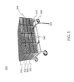
- FIG. 3 shows a perspective figure of a moveable cart carrying multiple battery cases, according to an embodiment.
- Batteries for hybrid or all-electric vehicles may present a number of difficulties which may, for example, reduce potential marketability of these vehicles.
- vehicle batteries may comprise relatively heavy assemblies having size or weight leading to physically unsafe conditions for manually handling the batteries under Occupational Safety and Health Administration (OSHA) handling guidelines or standards.
- OSHA Occupational Safety and Health Administration
- relatively expensive mechanical equipment may be involved in installation, removal, or maintenance of vehicle batteries.
- imbedding vehicle batteries within a body of a vehicle may lead to difficult or cumbersome processes for maintenance or safety inspections. Thus, for example, troublesome maintenance or safety inspections may be skipped from time to time.
- vehicle batteries not adequately inspected are known to have caused major vehicle fires.
- some methods of recharging vehicle batteries may involve leaving the batteries in a vehicle because of the difficulty in handling the batteries. Recharging vehicle batteries left in a vehicle may lead to relatively long recharge-service times (e.g., a vehicle incapacitated for one or more hours) based, at least in part, on a cycle time of a method to recharge the batteries.
- fast-charge methods which may be relatively expensive, may improve upon slower recharge methods, but may be significantly slower than a method of replacing spent batteries with freshly charged batteries.
- a heavy-single-module replacement system which may have a relatively slow cycle time, may cost over $500,000 in capital equipment, for example.
- gas or diesel power refill may be performed (e.g., at a gas station) in a few minutes.
- hybrid or all-electric vehicles may operate using a plurality of relatively heavy vehicle batteries. Throughout a life of a hybrid or all-electric vehicle, such vehicle batteries may be removed or replaced for charging, maintenance, inspection, retirement, and so on. Handling a large number of heavy vehicle batteries may lead to a cumbersome or physically harmful experience. Accordingly, a battery case to hold a plurality of vehicle batteries may include features to allow for relatively easy or fast removal or insertion. For example, a battery case may provide a benefit in that a vehicle need not be dissembled to remove or add vehicle batteries. In one implementation, a battery case may be attached to a portion of a hybrid or all-electric vehicle so that batteries stored in the battery case may supply electric power to the vehicle. In another implementation, a plurality of battery cases may be stacked on a workbench or cart, for example, so that maintenance or charging may be performed on batteries stored in the battery cases.
- a vehicle battery case may be incorporated within a hybrid-powered vehicle or a non-gas-powered vehicle, such as an all-electric vehicle, for example.
- a vehicle battery case may also be incorporated within a gas-powered vehicle, and claimed subject matter is not limited in this respect.
- a battery case may include ridges (e.g., “slides”) on which vehicle batteries may slide during insertion or removal of the batteries to or from the battery case. Ridges may comprise a material that allows for a relatively small amount of sliding friction between the ridges and vehicle batteries. In addition to reduced friction, ridges of a battery case may comprise a relatively small surface area on which vehicle batteries slide, compared to a surface area of a bottom of the battery case. Ridges having a relatively small amount of friction may be used in lieu of mechanical sliders or rollers that may include bearings, gears, shafts, and so on, for example. Accordingly, a battery case may comprise a relatively simple or easily manufacturable shape that need not use sliders or rollers to facilitate moving relatively heavy vehicle batteries, though sliders or rollers may be utilized in some embodiments.
- ridges e.g., “slides”
- Ridges may comprise a material that allows for a relatively small amount of sliding friction between the ridges and vehicle batteries.
- relatively heavy batteries may have a weight over ten pounds, though claimed subject matter is not so limited.
- a relatively heavy battery may be considered easy to slide, for example, if a user need not use an entire gripped hand to initiate or slide a battery. Instead, if a battery is considered easy to slide, then a user may use merely a few fingers to pull or push the battery, for example.
- Such details are merely examples, and claimed subject matter is not so limited.
- a vehicle battery case may comprise a housing at least partially enclosing a cavity to receive one or more vehicle batteries substantially along an axial direction of the cavity.
- An internal surface of a bottom portion of the housing may include one or more slides on which vehicle batteries may slide with relatively low sliding resistance (e.g., kinetic friction).
- internal surfaces of top or side portions of a housing may include one or more slides.
- Slides may comprise elongate ridges that extend upward and substantially in parallel to an axial direction of the battery case cavity. Slides may at least partially support weight of one or more vehicle batteries during sliding or storing of the batteries, though claimed subject matter is not necessarily so limited.
- an elongate ridge may comprise a raised portion of an internal surface of housing material of a battery case.
- a raised portion of an internal surface of housing material may have a shape that is at least partially convex with respect to a cavity of the housing.
- Portions of housing material may further include one or more channels having a shape that is at least partially concave with respect to the cavity of the housing.
- external surfaces of the batteries may have a shape that corresponds to a shape of a cavity of the vehicle battery case.
- an external surface of a vehicle battery may include one or more features to correspond to a shape of an internal surface of a housing of a vehicle battery case.
- an external surface of a vehicle battery may include one or more elongate battery ridges that may be sized or positioned to correspond to one or more channels on an internal surface of a housing of a vehicle battery case.
- a correspondence for example, may comprise a male-female relationship between a raised portion of a vehicle battery and a channel of a vehicle battery case.
- one or more ridges on a battery may correspond to one or more ridges in a cavity of a vehicle battery case in a male-male relationship, and claimed subject matter is not limited in this regard.
- a vehicle battery case may accommodate vehicle batteries that comply with any of a number of manufacturing specifications or standards.
- a battery standard may specify a particular size, shape, or other physical feature for a vehicle battery.
- a battery standard may specify that vehicle batteries may be stackable or fit closely end-to-end, for example.
- vehicle batteries may operated with a cooling system to help maintain battery temperature below a particular level, for example.
- a vehicle battery case may include one or more duct inlets or outlets to allow for flow of a coolant, such as air, for example.
- FIG. 1 shows a vehicle example or embodiment, such as 110 , that includes an attached battery case (not shown), such as battery case 230 , shown in FIG. 2 , according to an embodiment.
- Vehicle 110 may comprise any of a number of types of hybrid or all-electric vehicles, such as, but not limited to, an automobile, an aircraft, or a boat, for example.
- a battery case which may be mounted or attached to an underside region of a vehicle, may hold one or more vehicle batteries 122 while being used as a power source for the vehicle.
- one or more vehicle batteries may merely be stored in a battery case and need not be used as a power source at times.
- An attached battery case may include a front port 115 that may include a cover 117 that may be hinged.
- One or more vehicle batteries 122 may be inserted into or removed from a battery case, as indicated by arrow 105 , for example. Inserting or removing batteries may be facilitated by one or more low-friction slides (e.g., shown in FIG. 2 ) disposed inside a cavity of a battery housing. Accordingly, one or more vehicle batteries 122 may be slid into or out from the cavity while weight of the vehicle battery is at least partially supported by the one or more low-friction slides.
- a vehicle battery may have a height or width substantially the same as that of a cavity of a battery case. However, a length of a vehicle battery may be less than that of a cavity of a battery case. Accordingly, multiple batteries may extend from a rear end to a front end of a battery case.
- one vehicle battery may be inserted into the cavity following another vehicle battery so that a plurality of batteries may be placed into the cavity of a battery case. For example, a second inserted battery following a first inserted battery may physically contact the first battery so that a user pushing on the second battery may impart a force on the first battery via the second battery.
- physical contact among two or more batteries may facilitate electrical contact among batteries. Sliding friction between the plurality of sliding batteries and the cavity of the battery case may be relatively low so that a user sliding several batteries together in the cavity need not experience significant resistance.
- vehicle batteries may have a length approximately the same as a length of a cavity of a battery case. Accordingly, a single battery may extend approximately from a rear end to a front end of battery case. In yet another implementation, vehicle batteries may have a height substantially less than a height of a cavity of a battery case. Accordingly, multiple batteries may be placed or stacked upon one another inside the cavity. An example of such a situation is shown in FIG. 2 , for example.
- FIG. 2 includes perspective figures of vehicle batteries and a battery case, according to an embodiment.
- the figure on the left shows a cutaway view of a vehicle battery example or embodiment, such as 220 , inserted in a cavity of a battery case 230 .
- the figure in the center shows vehicle batteries 220 .
- the figure on the right shows battery case 230 without batteries.
- a vehicle battery case 230 may comprise a housing 231 at least partially enclosing cavity 233 to receive one or more vehicle batteries 220 substantially along an axial direction of the cavity.
- a bottom portion 235 B of housing 231 may include one or more slides 245 on which vehicle batteries 220 may slide with relatively low sliding resistance.
- top portion 235 T or side portions 235 A, C of housing 231 may include one or more slides or channels, such as channel 240 , for example. Slides may at least partially support weight of one or more vehicle batteries during sliding or storing of the batteries. For example, the direction of gravity with respect to vehicle battery case 230 in one particular embodiment is shown in FIG. 2 .
- vehicle batteries 220 may have a length approximately the same as a length of a cavity 233 of battery case 230 . Accordingly, a single battery may extend from a rear end 270 to a front end of battery case 230 . In yet another implementation, vehicle batteries may have a height substantially less than an inside height of a cavity of a battery case. Accordingly, multiple batteries 220 may be placed or stacked upon one another inside cavity 233 , for example.
- battery case 230 may include slides 245 on which battery 220 may be slid into or out of cavity 233 . Between or among slides 245 , one or more recessed portions 250 may comprise a portion of battery case 230 that need not contact batteries inserted in cavity 233 , for example. In particular, if a direction of gravity is as shown in FIG. 2 , then bottom portion 235 B of battery case 230 may at least partially support a weight of vehicle batteries 220 . Accordingly, it may be desirable to include slides 245 and recessed portions 250 to reduce area of contact between bottom portion 235 B and batteries in cavity 233 .
- slides may comprise a material having relatively low friction.
- a polyethylene-type material may provide a relatively slippery surface on which (e.g., heavy) batteries may be relatively easily moved.
- Other materials such as any of a number of types of plastics or metals, for example, may also be used as slide material or housing material, and claimed subject matter is not so limited.
- a coefficient of friction between one or more slides and one or more vehicle batteries may comprise a value less than about 0.20, for example.
- Recessed portions 250 may provide a benefit in that dirt or other material may accumulate in recessed portions 250 where the dirt or material may be out of the way of a sliding vehicle battery. In other words, recessed portions 250 may provide a space where undesirable material may accumulate, thus helping to maintain cleanliness of slides 245 , for example. Also, undesirable material accumulated in recessed portions 250 may be relatively easy to remove, thus allowing slides 245 , areas surrounding slides 245 , or recessed portions 250 , for example, to be relatively easy to clean.
- a vehicle battery may have a shape that corresponds to a shape of a vehicle battery case.
- vehicle battery 220 may include one or more raised battery portions, such as 222 , 224 , or 226 .
- Raised portions may correspond to recessed portions of a vehicle battery case.
- raised portion 226 may correspond to channel 240 of vehicle battery case 230 .
- raised battery portions may correspond to raised portions or slides of a vehicle battery case.
- raised portions 222 may correspond to slides 245 of vehicle battery case 230 .
- one or more raised portions 224 disposed on sides of battery 220 may provide bumpers to guide battery 220 during contact with sides 235 A, C from time to time while battery 220 is slid into or out of cavity 233 , for example.
- one or more raised portions 224 providing bumpers to contact sides 235 A, C from time to time may be useful while battery 220 is stationary in cavity 233 but while vehicle battery case 230 is in motion with a moving vehicle (e.g., shaking or jostling motion).
- raised portions 224 may be useful for holding battery 220 at least approximately in a particular position in cavity 233 during vehicle motion.
- Vehicle battery 220 may also include a handle that a user may use to pull or push battery 220 out of or into cavity 233 , for example.
- a vehicle battery may comprise any number of electronic features, such as a charge-light indicator 227 or a plug 229 , for example.
- Indicator 227 may include a battery condition indicator (e.g., charge level, temperature, and so on), for example.
- Plug 229 may be used to electrically connect one battery to another or to electrically connect one or more batteries to a vehicle electrical system 102 , for example.
- rear end 270 may comprise an end-cap including openings for electrical cables to connect among one or more batteries and a vehicle electrical system.
- rear end 270 may comprise electrical plugs on an internal surface to receive connections of one or more batteries to connect among the one or more batteries and a vehicle electrical system.
- rear end 270 may comprise one or more openings (not shown) to accommodate inlet or outlet ducts for cooling vehicle batteries located in cavity 233 .
- air may flow through cavity 233 to cool batteries 220 .
- Inlet or outlet ducts may be located in other portions of vehicle battery case 230 , such as portions 235 A, 235 B, 235 C, or 235 T, for example.
- portions 235 A, 235 B, 235 C, or 235 T for example.
- extruded or molded polyethylene-type material may lead to a housing 231 that is relatively strong, has relatively low friction with many other materials, is relatively resistant to acids, or is water resistant.
- an extrusion or molding process may allow for a housing 231 that need not include seams.
- Extruded or molded polyethylene-type material may also allow for housing 231 that has a cross-sectional shape comprising any of a number of possibilities, such as rectangular, square, circular, oval, and so on.
- any of a number of cross-sectional shapes may be attained by any of a number of methods of manufacturing other than extrusion or molding, and claimed subject matter is not so limited.
- a plurality of vehicle batteries may be removed from a hybrid vehicle for inspection or electrical measurements and placed into cavities 333 of battery cases 330 on cart 300 . Insertion or removal of vehicle batteries may be facilitated by one or more slides 345 included in individual battery cases 330 that may lead to a relatively low amount of friction while sliding the vehicle batteries into or out of cavity 333 , for example.
- a moveable cart is merely examples, and claimed subject matter is not so limited.
Abstract
Description
Claims (20)
Priority Applications (1)
| Application Number | Priority Date | Filing Date | Title |
|---|---|---|---|
| US13/353,060 US8852794B2 (en) | 2012-01-18 | 2012-01-18 | Electric vehicle battery case |
Applications Claiming Priority (1)
| Application Number | Priority Date | Filing Date | Title |
|---|---|---|---|
| US13/353,060 US8852794B2 (en) | 2012-01-18 | 2012-01-18 | Electric vehicle battery case |
Publications (2)
| Publication Number | Publication Date |
|---|---|
| US20130183561A1 US20130183561A1 (en) | 2013-07-18 |
| US8852794B2 true US8852794B2 (en) | 2014-10-07 |
Family
ID=48780184
Family Applications (1)
| Application Number | Title | Priority Date | Filing Date |
|---|---|---|---|
| US13/353,060 Active 2032-08-05 US8852794B2 (en) | 2012-01-18 | 2012-01-18 | Electric vehicle battery case |
Country Status (1)
| Country | Link |
|---|---|
| US (1) | US8852794B2 (en) |
Cited By (22)
| Publication number | Priority date | Publication date | Assignee | Title |
|---|---|---|---|---|
| US20150064503A1 (en) * | 2012-03-16 | 2015-03-05 | Daisuke Kawaguchi | Battery containing body and power storage device |
| US20150114736A1 (en) * | 2013-10-28 | 2015-04-30 | Meir Avganim | Quick loading and unloading battery system for vehicles |
| US9566954B2 (en) | 2014-03-10 | 2017-02-14 | Max Moskowitz | Vehicular accessory |
| US20180105062A1 (en) * | 2016-10-14 | 2018-04-19 | Inevit, Inc. | Battery module compartment chamber and battery module mounting area of an energy storage system and method thereof |
| US10358169B2 (en) * | 2015-03-06 | 2019-07-23 | Ford Global Technologies, Llc | Coverless battery assembly for electrified vehicle |
| US10483510B2 (en) | 2017-05-16 | 2019-11-19 | Shape Corp. | Polarized battery tray for a vehicle |
| WO2019224199A1 (en) | 2018-05-22 | 2019-11-28 | Sgl Carbon Se | Stored energy source protected by a composite material |
| US10549729B2 (en) | 2014-03-10 | 2020-02-04 | Max Moskowitz | Vehicular accessory |
| US10632857B2 (en) | 2016-08-17 | 2020-04-28 | Shape Corp. | Battery support and protection structure for a vehicle |
| US10661646B2 (en) | 2017-10-04 | 2020-05-26 | Shape Corp. | Battery tray floor assembly for electric vehicles |
| US20200164760A1 (en) * | 2017-07-19 | 2020-05-28 | Ford Global Technologies, Llc | Swappable battery system |
| US10886513B2 (en) | 2017-05-16 | 2021-01-05 | Shape Corp. | Vehicle battery tray having tub-based integration |
| US11065967B2 (en) | 2018-08-08 | 2021-07-20 | The Raymond Corporation | Systems and methods for a modular battery system |
| US11088412B2 (en) | 2017-09-13 | 2021-08-10 | Shape Corp. | Vehicle battery tray with tubular peripheral wall |
| US11121427B1 (en) * | 2019-01-25 | 2021-09-14 | Julian Enrique Bustamante Laparra | Stabilizing electric battery system for vehicles |
| US11155150B2 (en) | 2018-03-01 | 2021-10-26 | Shape Corp. | Cooling system integrated with vehicle battery tray |
| US11211656B2 (en) | 2017-05-16 | 2021-12-28 | Shape Corp. | Vehicle battery tray with integrated battery retention and support feature |
| US11214137B2 (en) | 2017-01-04 | 2022-01-04 | Shape Corp. | Vehicle battery tray structure with nodal modularity |
| WO2021181125A3 (en) * | 2018-08-14 | 2022-01-13 | Black & Decker, Inc. | Power tool system |
| US11233291B2 (en) | 2019-04-03 | 2022-01-25 | The Raymond Corporation | Systems and methods for a modular battery system |
| US11688910B2 (en) | 2018-03-15 | 2023-06-27 | Shape Corp. | Vehicle battery tray having tub-based component |
| US11923557B2 (en) | 2018-08-14 | 2024-03-05 | Black & Decker Inc. | Battery pack |
Families Citing this family (12)
| Publication number | Priority date | Publication date | Assignee | Title |
|---|---|---|---|---|
| EP3497776A4 (en) * | 2016-08-10 | 2020-02-05 | Briggs & Stratton Corporation | User-scalable power unit including removable battery packs |
| FR3067662B1 (en) * | 2017-06-16 | 2019-11-29 | Valeo Equipements Electriques Moteur | LOW VOLTAGE HYBRID TRACTION ARCHITECTURE FOR A VEHICLE EMBARKING A PORTABLE BATTERY |
| KR102334141B1 (en) * | 2017-10-31 | 2021-12-02 | 주식회사 엘지에너지솔루션 | Secondary Battery Comprising Battery Case Formed by Injection Molding |
| KR102330869B1 (en) * | 2018-01-17 | 2021-11-23 | 주식회사 엘지에너지솔루션 | Manufacturing Apparatus for Battery Module and Method for Manufacturing Battery Module |
| CN108715129B (en) * | 2018-05-28 | 2020-12-22 | 江苏赛朗热能技术有限公司 | New forms of energy electric automobile battery pack |
| CN108715128B (en) * | 2018-05-28 | 2021-01-05 | 嘉兴琦玥装饰材料有限公司 | New forms of energy pure electric bus |
| CN108705947B (en) * | 2018-05-28 | 2020-12-18 | 南京蓝领环境科技有限公司 | New forms of energy electric automobile |
| CN108909474B (en) * | 2018-05-28 | 2021-01-05 | 嘉兴琦玥装饰材料有限公司 | New forms of energy electric bus |
| CN108674391B (en) * | 2018-05-28 | 2021-03-16 | 云南西塔新工业科技有限公司 | New energy electric automobile |
| ES2735302B2 (en) | 2018-06-14 | 2020-07-28 | Remon Rodriguez Daniel | Vehicle energy storage system |
| US20230187754A1 (en) * | 2021-12-15 | 2023-06-15 | The Noco Company | Battery box |
| GB2616594A (en) * | 2022-03-07 | 2023-09-20 | David Alcraft Francis | Removable cassettes |
Citations (10)
| Publication number | Priority date | Publication date | Assignee | Title |
|---|---|---|---|---|
| US3930552A (en) | 1974-10-30 | 1976-01-06 | Fmc Corporation | Motor vehicle battery holder |
| US4216839A (en) * | 1978-07-20 | 1980-08-12 | Unique Mobility Inc. | Electrically powered motor vehicle |
| US5760569A (en) * | 1997-02-26 | 1998-06-02 | Chase, Jr.; Robert B. | Replaceable battery module for electric vehicle |
| US6003924A (en) | 1996-11-08 | 1999-12-21 | Nicol; Robert E. | Modular drawer system |
| US20020155348A1 (en) * | 1996-05-28 | 2002-10-24 | Gitto/Global Corporation | Flame-retardant battery casing |
| US20080118828A1 (en) * | 2006-11-22 | 2008-05-22 | Dudlee Brennfoerder | Dual voltage battery with separate terminals |
| US20090325058A1 (en) * | 2007-05-10 | 2009-12-31 | Hideaki Katayama | Electrochemical device and method for production thereof |
| US7712563B2 (en) | 2006-07-07 | 2010-05-11 | Jungheinrich Aktiengesellschaft | Battery exchange system for a battery-driven industrial truck |
| US7732092B2 (en) | 2005-03-23 | 2010-06-08 | Sk Energy Co., Ltd. | Case for high-power rechargeable lithium battery |
| US7948207B2 (en) | 2006-02-09 | 2011-05-24 | Karl Frederick Scheucher | Refuelable battery-powered electric vehicle |
-
2012
- 2012-01-18 US US13/353,060 patent/US8852794B2/en active Active
Patent Citations (10)
| Publication number | Priority date | Publication date | Assignee | Title |
|---|---|---|---|---|
| US3930552A (en) | 1974-10-30 | 1976-01-06 | Fmc Corporation | Motor vehicle battery holder |
| US4216839A (en) * | 1978-07-20 | 1980-08-12 | Unique Mobility Inc. | Electrically powered motor vehicle |
| US20020155348A1 (en) * | 1996-05-28 | 2002-10-24 | Gitto/Global Corporation | Flame-retardant battery casing |
| US6003924A (en) | 1996-11-08 | 1999-12-21 | Nicol; Robert E. | Modular drawer system |
| US5760569A (en) * | 1997-02-26 | 1998-06-02 | Chase, Jr.; Robert B. | Replaceable battery module for electric vehicle |
| US7732092B2 (en) | 2005-03-23 | 2010-06-08 | Sk Energy Co., Ltd. | Case for high-power rechargeable lithium battery |
| US7948207B2 (en) | 2006-02-09 | 2011-05-24 | Karl Frederick Scheucher | Refuelable battery-powered electric vehicle |
| US7712563B2 (en) | 2006-07-07 | 2010-05-11 | Jungheinrich Aktiengesellschaft | Battery exchange system for a battery-driven industrial truck |
| US20080118828A1 (en) * | 2006-11-22 | 2008-05-22 | Dudlee Brennfoerder | Dual voltage battery with separate terminals |
| US20090325058A1 (en) * | 2007-05-10 | 2009-12-31 | Hideaki Katayama | Electrochemical device and method for production thereof |
Non-Patent Citations (2)
| Title |
|---|
| Squatriglia, "Better Place Unveils an Electric Car Battery Swap Station," Autopia, Planes, Trains, Automobiles and the Future of Transportation, Categories; EVs and Hybrids, May 13, 2009, 20 pages. |
| Storeaway, New Vehicle Storage System!, Canby, OR, 4 pages, Dec. 21, 1999. |
Cited By (32)
| Publication number | Priority date | Publication date | Assignee | Title |
|---|---|---|---|---|
| US20150064503A1 (en) * | 2012-03-16 | 2015-03-05 | Daisuke Kawaguchi | Battery containing body and power storage device |
| US10056586B2 (en) * | 2012-03-16 | 2018-08-21 | Nec Corporation | Battery containing body and power storage device |
| US20150114736A1 (en) * | 2013-10-28 | 2015-04-30 | Meir Avganim | Quick loading and unloading battery system for vehicles |
| US9358895B2 (en) * | 2013-10-28 | 2016-06-07 | Meir Avganim | Quick loading and unloading battery system for vehicles |
| US10549729B2 (en) | 2014-03-10 | 2020-02-04 | Max Moskowitz | Vehicular accessory |
| US9566954B2 (en) | 2014-03-10 | 2017-02-14 | Max Moskowitz | Vehicular accessory |
| US9834183B2 (en) | 2014-03-10 | 2017-12-05 | Max Moskowitz | Vehicular accessory |
| US10358169B2 (en) * | 2015-03-06 | 2019-07-23 | Ford Global Technologies, Llc | Coverless battery assembly for electrified vehicle |
| US11660950B2 (en) | 2016-08-17 | 2023-05-30 | Shape Corp. | Battery support and protection structure for a vehicle |
| US10632857B2 (en) | 2016-08-17 | 2020-04-28 | Shape Corp. | Battery support and protection structure for a vehicle |
| US11273697B2 (en) | 2016-08-17 | 2022-03-15 | Shape Corp. | Battery support and protection structure for a vehicle |
| US20180108891A1 (en) * | 2016-10-14 | 2018-04-19 | Inevit, Inc. | Battery module compartment and battery module arrangement of an energy storage system |
| US20180105062A1 (en) * | 2016-10-14 | 2018-04-19 | Inevit, Inc. | Battery module compartment chamber and battery module mounting area of an energy storage system and method thereof |
| US11214137B2 (en) | 2017-01-04 | 2022-01-04 | Shape Corp. | Vehicle battery tray structure with nodal modularity |
| US11691493B2 (en) | 2017-05-16 | 2023-07-04 | Shape Corp. | Vehicle battery tray having tub-based component |
| US10886513B2 (en) | 2017-05-16 | 2021-01-05 | Shape Corp. | Vehicle battery tray having tub-based integration |
| US11211656B2 (en) | 2017-05-16 | 2021-12-28 | Shape Corp. | Vehicle battery tray with integrated battery retention and support feature |
| US10483510B2 (en) | 2017-05-16 | 2019-11-19 | Shape Corp. | Polarized battery tray for a vehicle |
| US20200164760A1 (en) * | 2017-07-19 | 2020-05-28 | Ford Global Technologies, Llc | Swappable battery system |
| US11088412B2 (en) | 2017-09-13 | 2021-08-10 | Shape Corp. | Vehicle battery tray with tubular peripheral wall |
| US10960748B2 (en) | 2017-10-04 | 2021-03-30 | Shape Corp. | Battery tray floor assembly for electric vehicles |
| US11267327B2 (en) | 2017-10-04 | 2022-03-08 | Shape Corp. | Battery tray floor assembly for electric vehicles |
| US10661646B2 (en) | 2017-10-04 | 2020-05-26 | Shape Corp. | Battery tray floor assembly for electric vehicles |
| US11787278B2 (en) | 2017-10-04 | 2023-10-17 | Shape Corp. | Battery tray floor assembly for electric vehicles |
| US11155150B2 (en) | 2018-03-01 | 2021-10-26 | Shape Corp. | Cooling system integrated with vehicle battery tray |
| US11688910B2 (en) | 2018-03-15 | 2023-06-27 | Shape Corp. | Vehicle battery tray having tub-based component |
| WO2019224199A1 (en) | 2018-05-22 | 2019-11-28 | Sgl Carbon Se | Stored energy source protected by a composite material |
| US11065967B2 (en) | 2018-08-08 | 2021-07-20 | The Raymond Corporation | Systems and methods for a modular battery system |
| WO2021181125A3 (en) * | 2018-08-14 | 2022-01-13 | Black & Decker, Inc. | Power tool system |
| US11923557B2 (en) | 2018-08-14 | 2024-03-05 | Black & Decker Inc. | Battery pack |
| US11121427B1 (en) * | 2019-01-25 | 2021-09-14 | Julian Enrique Bustamante Laparra | Stabilizing electric battery system for vehicles |
| US11233291B2 (en) | 2019-04-03 | 2022-01-25 | The Raymond Corporation | Systems and methods for a modular battery system |
Also Published As
| Publication number | Publication date |
|---|---|
| US20130183561A1 (en) | 2013-07-18 |
Similar Documents
| Publication | Publication Date | Title |
|---|---|---|
| US8852794B2 (en) | Electric vehicle battery case | |
| US9966712B1 (en) | Battery plug-in device for material handling equipment | |
| CN107004784B (en) | Lithium ion battery module comprising free floating cells and method for producing the same | |
| US20150243950A1 (en) | Onboard battery | |
| AU2008200543B8 (en) | Light-weight, Mass-producible, Combined Chassis, Battery Housing, Cooling System Structure for Solar Electric Vehicle | |
| US9193316B2 (en) | Battery enclosure systems and methods | |
| US10367179B2 (en) | Battery pack | |
| US20100291418A1 (en) | Battery packs, systems, and methods | |
| US9145045B2 (en) | Battery pack holding apparatus | |
| CN204077299U (en) | Electronic cold insulation car | |
| US20050269995A1 (en) | Design of a Large battery pack for a hybrid locomotive | |
| US20120068662A1 (en) | Portable Battery Booster | |
| EP3309001A1 (en) | Battery plug-in device for material handling equipment | |
| US9738299B2 (en) | Mother daughter cart system | |
| CN107004782B (en) | Lithium ion battery module with free-floating prismatic cells | |
| US10219667B2 (en) | Vacuum cleaner and battery assembly | |
| KR101279416B1 (en) | Battery case for electric vehicle | |
| KR20200128070A (en) | Mounting and removal system for battery assembly | |
| WO2012031458A1 (en) | Parallel charging device for multiple power batteries | |
| US20230238758A1 (en) | Power adapter | |
| US20110244291A1 (en) | Cooling system for a battery pack | |
| CN113611907A (en) | Lithium battery clamp vehicle type vacuum baking equipment and lithium battery production line | |
| CN112074427B (en) | Energy storage system for a vehicle | |
| US20220093900A1 (en) | Power tool battery pack receptacle | |
| JP2020181812A (en) | Battery cartridge |
Legal Events
| Date | Code | Title | Description |
|---|---|---|---|
| AS | Assignment |
Owner name: BATTCHANGE, LLC, OREGON Free format text: ASSIGNMENT OF ASSIGNORS INTEREST;ASSIGNOR:LAITINEN, ERNEST W.;REEL/FRAME:028807/0611 Effective date: 20120817 |
|
| STCF | Information on status: patent grant |
Free format text: PATENTED CASE |
|
| MAFP | Maintenance fee payment |
Free format text: PAYMENT OF MAINTENANCE FEE, 4TH YEAR, LARGE ENTITY (ORIGINAL EVENT CODE: M1551) Year of fee payment: 4 |
|
| FEPP | Fee payment procedure |
Free format text: MAINTENANCE FEE REMINDER MAILED (ORIGINAL EVENT CODE: REM.); ENTITY STATUS OF PATENT OWNER: LARGE ENTITY |
|
| FEPP | Fee payment procedure |
Free format text: 7.5 YR SURCHARGE - LATE PMT W/IN 6 MO, LARGE ENTITY (ORIGINAL EVENT CODE: M1555); ENTITY STATUS OF PATENT OWNER: LARGE ENTITY |
|
| MAFP | Maintenance fee payment |
Free format text: PAYMENT OF MAINTENANCE FEE, 8TH YEAR, LARGE ENTITY (ORIGINAL EVENT CODE: M1552); ENTITY STATUS OF PATENT OWNER: LARGE ENTITY Year of fee payment: 8 |