US8851564B2 - Chair with foldable desk - Google Patents
Chair with foldable desk Download PDFInfo
- Publication number
- US8851564B2 US8851564B2 US13/300,065 US201113300065A US8851564B2 US 8851564 B2 US8851564 B2 US 8851564B2 US 201113300065 A US201113300065 A US 201113300065A US 8851564 B2 US8851564 B2 US 8851564B2
- Authority
- US
- United States
- Prior art keywords
- coupler
- joint
- chair
- desk
- support leg
- Prior art date
- Legal status (The legal status is an assumption and is not a legal conclusion. Google has not performed a legal analysis and makes no representation as to the accuracy of the status listed.)
- Expired - Fee Related, expires
Links
- 238000010168 coupling process Methods 0.000 claims description 27
- 238000005859 coupling reaction Methods 0.000 claims description 27
- 230000008878 coupling Effects 0.000 claims description 26
- 230000000149 penetrating effect Effects 0.000 claims description 2
- 230000003993 interaction Effects 0.000 description 2
- 241001125620 Dermochelys coriacea Species 0.000 description 1
- 230000009471 action Effects 0.000 description 1
- 230000015556 catabolic process Effects 0.000 description 1
- 238000006731 degradation reaction Methods 0.000 description 1
- 239000004744 fabric Substances 0.000 description 1
- 239000004033 plastic Substances 0.000 description 1
Images


Classifications
-
- A—HUMAN NECESSITIES
- A47—FURNITURE; DOMESTIC ARTICLES OR APPLIANCES; COFFEE MILLS; SPICE MILLS; SUCTION CLEANERS IN GENERAL
- A47C—CHAIRS; SOFAS; BEDS
- A47C7/00—Parts, details, or accessories of chairs or stools
- A47C7/62—Accessories for chairs
- A47C7/68—Arm-rest tables ; or back-rest tables
- A47C7/70—Arm-rest tables ; or back-rest tables of foldable type
-
- A—HUMAN NECESSITIES
- A47—FURNITURE; DOMESTIC ARTICLES OR APPLIANCES; COFFEE MILLS; SPICE MILLS; SUCTION CLEANERS IN GENERAL
- A47C—CHAIRS; SOFAS; BEDS
- A47C7/00—Parts, details, or accessories of chairs or stools
- A47C7/62—Accessories for chairs
- A47C7/68—Arm-rest tables ; or back-rest tables
- A47C7/705—Arm-rest tables ; or back-rest tables of detachable type
-
- F—MECHANICAL ENGINEERING; LIGHTING; HEATING; WEAPONS; BLASTING
- F16—ENGINEERING ELEMENTS AND UNITS; GENERAL MEASURES FOR PRODUCING AND MAINTAINING EFFECTIVE FUNCTIONING OF MACHINES OR INSTALLATIONS; THERMAL INSULATION IN GENERAL
- F16B—DEVICES FOR FASTENING OR SECURING CONSTRUCTIONAL ELEMENTS OR MACHINE PARTS TOGETHER, e.g. NAILS, BOLTS, CIRCLIPS, CLAMPS, CLIPS OR WEDGES; JOINTS OR JOINTING
- F16B12/00—Jointing of furniture or the like, e.g. hidden from exterior
- F16B12/10—Jointing of furniture or the like, e.g. hidden from exterior using pegs, bolts, tenons, clamps, clips, or the like
-
- A—HUMAN NECESSITIES
- A47—FURNITURE; DOMESTIC ARTICLES OR APPLIANCES; COFFEE MILLS; SPICE MILLS; SUCTION CLEANERS IN GENERAL
- A47B—TABLES; DESKS; OFFICE FURNITURE; CABINETS; DRAWERS; GENERAL DETAILS OF FURNITURE
- A47B2220/00—General furniture construction, e.g. fittings
- A47B2220/0036—Brackets
-
- A—HUMAN NECESSITIES
- A47—FURNITURE; DOMESTIC ARTICLES OR APPLIANCES; COFFEE MILLS; SPICE MILLS; SUCTION CLEANERS IN GENERAL
- A47C—CHAIRS; SOFAS; BEDS
- A47C7/00—Parts, details, or accessories of chairs or stools
- A47C7/36—Support for the head or the back
- A47C7/40—Support for the head or the back for the back
- A47C7/44—Support for the head or the back for the back with elastically-mounted back-rest or backrest-seat unit in the base frame
- A47C7/443—Support for the head or the back for the back with elastically-mounted back-rest or backrest-seat unit in the base frame with coil springs
-
- A—HUMAN NECESSITIES
- A47—FURNITURE; DOMESTIC ARTICLES OR APPLIANCES; COFFEE MILLS; SPICE MILLS; SUCTION CLEANERS IN GENERAL
- A47C—CHAIRS; SOFAS; BEDS
- A47C7/00—Parts, details, or accessories of chairs or stools
- A47C7/56—Parts or details of tipping-up chairs, e.g. of theatre chairs
Definitions
- the present invention relates to a chair with a foldable desk, and more particularly to a chair which enables the desk located above a side of the chair to be folded/unfolded by way of an upward/downward swing or a rotation on a horizontal plane and which enables the desk to be disassembled or assembled as necessary. Also, the present invention relates to the chair including such functions as back-tilting or seat plate folding, so that the productivity, the functionality, the economy and the convenience thereof can be improved.
- the chair comprises a support leg, a seat plate and a back.
- the chair has been manufactured in many ways in consideration of its functional aspect as well as the design aspect.
- the foldable-seat plate structure and the tilting function of the backseat provide the user with the better comfort, along with the availability of space.
- the conventional chair has a complex structure so as to take various functions into the consideration. Also, the degradation in the productivity and the economy is caused, because expensive parts are included therein.
- a chair having a desk wherein the desk is fixed at its upper side of the chair so as to provide the function of the desk.
- the chair with the fixed desk improves the convenience, but it might cause the inconvenience when the desk is unnecessary. Also, it occupies too much space during carriage and storage.
- the present invention has been made to solve the above-mentioned problems occurring in the prior art, and the present invention provides a chair with a foldable desk which meets the requirements regarding the design, the productivity, the economy and the convenience.
- the object of the present invention provides a chair with a foldable desk, wherein the desk installed above at a side of the chair is folded or unfolded with the rotation of the desk on a horizontal plane and swing of the desk between an upper position and a lower position and wherein the desk is assembled to or disassembled from the chair.
- the chair according to the present invention provides the tilt operation of a back and the folding/unfolding operation of a seat plate, so that it can provides the maximized productivity, functionality and convenience.
- a chair with foldable desk which comprises: a support leg having a crossbar; a seat plate installed above said support leg and including an upper seat, a lower cover and a coupler into which the crossbar is rotatably inserted, wherein the coupler is formed by upper and lower brackets, each of which has a semi-circular coupling groove to form a circular space for receiving the crossbar, wherein the coupler is formed with a long-guide holes extended in a rotational direction of the crossbar to receive support protrusions formed on the crossbar, and wherein the seat plate rotates between a vertical position and a horizontal position so as to be folded and unfolded; a back installed above a rear side of the seat plate and capable of tilting forward and rearward by means of tilting means, wherein the tilting means comprises a tension spring between upper and lower connectors, which are connected to the back and the support leg, respectively; and a desk installed above a side of the support leg and including an upper plate with an
- the desk is detachably coupled to the chair in such a manner that a coupling bracket connected to an end of the connecting bar is releasably secured to a fixing bracket welded to a bent portion by means of bots, wherein the bent portion has a “>” shape and locates at a rear side of the support leg.
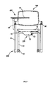
- FIG. 1 is a perspective view of a chair with a foldable desk according to the present invention.
- FIG. 2 is a side view of the chair according to an embodiment of the present invention.
- FIG. 3 is a front view of the chair according to the embodiment of the present invention.
- FIG. 4 is a bottom view of a seat plate included in the chair according to the embodiment of the present invention.
- FIG. 5A is a first sectional view illustrating a first operating state of the seat plate according to an embodiment of the present invention.
- FIG. 5B is a second sectional view illustrating a second operating state of the seat plate according to an embodiment of the present invention.
- FIG. 6 is a sectional view of tilting means included in the chair according to the embodiment of the present invention.
- FIG. 7 is an exploded view of the desk included in the chair according to the embodiment of the present invention.
- FIG. 8 is a top view of a joint included in the chair according to the embodiment of the present invention.
- FIG. 9 is a sectional view of the joint coupled to a coupler included in the chair according to the embodiment of the present invention.
- FIG. 10 is a partial section view of the desk included in the chair according to the embodiment of the present invention.
- FIG. 11 is an exploded view of a coupling bracket for securing the desk included in the chair according to the embodiment of the present invention.
- FIG. 12 is a top view of the chair according to the embodiment of the present invention, which illustrates the operation of the desk.
- FIG. 13 is a side view of the chair according to the embodiment of the present invention, which illustrates the desk folded near to the chair.
- a chair with a foldable desk of the present invention comprises: a support legs 100 ; seat plate 200 installed above said support leg 100 and capable of being folded between a horizontal position and a vertical position; a back 300 installed above a rear side of said seat plate 200 ; and a desk 400 installed above said support leg 100 .
- the support leg 100 comprises front and rear support members 12 and 13 at a front and rear side of a crossbar 11 that is centered thorough the front and rear support members 12 and 13 .
- Casters 15 are provided at lower ends of the front support members 12 .
- the seat plate 200 comprises an upper seat 21 , a lower cover 22 and .a coupler 23 , wherein the coupler 23 is located between the upper seat 21 and the lower cover 22 and wherein the crossbar 11 is rotatably coupled to the coupler 23 .
- the coupler 23 includes upper and lower brackets 26 and 26 ′, each of which forms a semi-circular coupling groove.
- the semi-circular coupling grooves of the brackets 26 and 26 ′ form a circular space therein when they are opposed to each other.
- the brackets 26 and 26 ′ are formed with long-guide holes 27 and 27 ′, respectively, in a rotational direction of the crossbar 11 .
- the crossbar 11 is formed with protrusions 120 and 120 ′, which is inserted into the long-guide holes 27 and 27 ′, respectively ( FIGS. 4 , 5 A, 5 B and 6 ). Accordingly, the seat plate 200 may be folded/unfolded between the horizontal and the vertical position, wherein the folding and unfolding action is guided by and the protrusions 120 and 120 ′ inserted in the long-guide holes 27 and 27 ′.
- the lower cover 22 may be formed with coupling holes (not shown) at either side thereof to be inserted by the crossbar 11 . Also, the lower cover 22 may be formed with coupling portions (not shown) at a lower part thereof to selectively receive a rotary-type leg member for use.
- the back 300 is connected to the support leg 100 through tilting means 30 so to be tilted forward and rearward.
- the tilting means 30 includes; an upper connector 31 connected to the back 300 ; a lower connector 31 ′ connected to the support leg 100 ; and a tension spring 32 connected between the upper and lower connectors 31 and 31 ′.
- a rubber cover 35 covers the upper and lower connectors 31 and 31 ′ and the tension spring 35 for finishing.
- the upper and lower connectors 31 and 31 ′ and the tension spring 32 are connected to each other in a thread-coupling manner.
- the back 300 may have many different types, such as a plastic back, a fabric or leather back, or a mesh-type back.
- an attachment member 49 is provided at a lower side of an upper plate 41 , wherein the attachment member 49 is formed with a coupling hole 41 a on a bottom face thereof and a stop boss 41 b within the coupling hole 41 a .
- the stop boss 41 b protrudes inwardly from an inner periphery of the coupling hole 41 a in a radial direction, and partially extends in a circumferential direction.
- a joint 42 is provided, which is formed with a support boss 42 a at its top portion. The support boss 42 a of the joint 42 is inserted into the coupling hole 41 a of the attachment member 49 to thereby enable the support boss 42 a to rotate in the coupling hole 41 a .
- the rotation of the support boss 42 a within the coupling hole 41 a is limited when the support boss 42 a contacts the stop boss 41 b depending on a rotational position of the upper plate 41 .
- the upper plate 41 may rotate on a horizontal plane, while its rotation is restricted when the support boss 42 a contacts the support boss 41 b.
- the joint 42 has a cylindrical shape which has a cylindrical surface, the top portion and a bottom portion.
- the joint 42 is formed with a assembling hole 42 b and an operating hole 42 c , wherein the assembling hole 42 b communicates with the operating hole 42 c .
- the assembling hole 42 b is formed to penetrate the cylindrical surface of the joint 42
- the operating hole 42 c extends along the bottom portion and a portion of the cylindrical surface of the joint 42 .
- the top portion of the joint 42 is blocked so as to make the support boss 42 a formed at the top portion of the joint 42 .
- a coupler 44 serves to connect a connecting bar 45 to the joint 42 , wherein the connecting bar 45 is connected to the support member 13 as illustrated in FIG. 2 .
- the coupler 44 is inserted into the assembling hole 42 b of the joint 42 so as to allow the joint 42 to swing about the coupler 44 .
- a bolt 43 is inserted into the operating hole 42 c of the joint 42 and then is screwed to the coupler 44 . Thereby, while the joint 42 swings about the coupler 44 , the bolt 43 may contact either limit of the assembling hole 42 b .
- the swing of the joint 42 is restricted within a certain angle range that is defined by the interaction between the joint 42 and the bolt 43 .
- the swing of the upper plate 41 coupled to the joint 42 through the attachment member 49 is restricted with the same angle range.
- the upper plate 41 of the desk 400 may swing between an upper position and a lower position within the angle range between 0 and 90°, as illustrated in FIG. 13 , while it may rotates on the horizontal plane within an angle range between 0 and 180°, as illustrated in FIG. 12 . Thereby, the upper plate 41 may be folded near to a side of the support member 13 .
- the desk 400 is connected to the support member 13 in such a way that a coupling bracket 46 connected to an end of the connecting bar 45 is detachably connected to a fixing bracket 16 welded to a bent portion 48 of the support member 13 by means of bolts 5 as illustrated in FIG. 10 .
- the bent portion 48 is formed to have ‘>’ shape at a rear side of the support member 13 as illustrated in FIG. 2 .
- the coupling bracket 46 allows an end of the connecting bar 45 to pass through a center hole 47 a of an inner recess 47 to thereby make the end of the connecting bar 45 and the coupling bracket 46 welded together as illustrated in FIG. 10 .
- a finishing cover 18 is provided outside of the fixing bracket 16 to enclose the fixing bracket 16 , so that the finishing cover 18 is assembled by means of bolts and nuts, which are used for the coupling bracket.
- FIG. 10 a bolt 19 used for fixing the finishing cover 18 is illustrated in FIG. 10 ; armrests 38 are illustrated in FIG. 1 ; and the case 46 is illustrated in FIG. 10 .
- the chair according to the present invention makes it possible to rotate the seat plate 200 , so that it is folded/unfolded between the horizontal position and the vertical position with the simple structure.
- the coupler 23 within the seat plate 200 rotates about the crossbar 11 of the support leg 100 .
- the protrusions 120 and 120 ′ formed on the crossbar 11 are inserted in the long-guide holes 27 and 27 ′ formed through the upper and lower brackets 26 and 26 ′ of the coupler 23 to be guided therein. Thereby, the rotation of the coupler 23 about the crossbar 11 is limited within a certain angle range.
- the seat plate 200 it is possible to rotate the seat plate 200 to be folded/unfolded between the horizontal position and the vertical position by means of the rotation of the coupler 23 .
- the availability of front/rear space of the chair may be enhanced by folding the seat plate 200 .
- the chair according to the present invention enables the back 300 to be tilted forward and rearward using the tilting means 30 with the simple structure.
- the tension spring 32 is installed between the upper connector 31 , which is connected to the back 300 , and the lower connector 31 ′, which is connected to the support leg 100 .
- the rubber cover 35 encloses the exterior of the tension spring 32 and the connectors 31 and 31 ′.
- the chair according to the present invention enables the desk 400 , which is located above the support leg 100 , to be used in a foldable manner and to be conveniently removed from the chair when it is needed.
- the attachment/the removal of the desk 400 to/from the chair is available in a convenient manner by screwing/unscrewing the bolts 5 between the connecting bracket 46 connected at the end of the connecting bar 45 , and the fixing bracket 16 welded to the bent portion 15 , which has the “>” shape at the rear side of the support leg 13 .
- the better availability of the space can be provided during carriage and storage.
- the desk 400 can be used in a folded or unfolded state.
- the support boss 42 a formed at the top of the joint 42 is rotated within the coupling hole 41 a until it abuts the stop boss 41 a . Accordingly, the rotation of the upper plate 41 is made with the angle range defined by the engagement between the support boss 42 a and the stop boss 41 a .
- the upper plate 42 a may rotate within the angle range of 180°.
- the upper plate 41 When rotating the upper plate 41 upward or downward, the upper plate 41 is rotated about the coupler 44 inserted into the assembling hole 42 b of the joint 42 .
- the stop bolt 43 is inserted through the operating hole 42 c to be screwed to the coupler 44 . Accordingly, the upper plate 41 rotates upward or downward within an angle range of 90° that is defined by guiding the stop bolt 43 in the operating hole 42 c.
- the desk 400 may be folded to contact the side of the chair as illustrated in FIG. 13 .
- the operation should proceed in a reverse order.
- the desk 400 swings upward with the angle range of 90° and then rotates to an original position with the angle range of 180° for use.
Abstract
A chair with a foldable desk includes a support leg having a crossbar. A seat plate installed above said support leg includes an upper seat, a lower cover and a coupler into which the crossbar is rotatably inserted. The seat plate rotates between a vertical position and a horizontal position. A back installed above a rear side of the seat plate is capable of tilting forward and rearward with tilting means. A desk installed above a side of the support leg includes an upper plate with an attachment member on its bottom. The upper plate may swing between an upper position and a lower position within an angle range.
Description
1. Field of the Invention
The present invention relates to a chair with a foldable desk, and more particularly to a chair which enables the desk located above a side of the chair to be folded/unfolded by way of an upward/downward swing or a rotation on a horizontal plane and which enables the desk to be disassembled or assembled as necessary. Also, the present invention relates to the chair including such functions as back-tilting or seat plate folding, so that the productivity, the functionality, the economy and the convenience thereof can be improved.
2. Description of the Related Art
Generally, the chair comprises a support leg, a seat plate and a back. The chair has been manufactured in many ways in consideration of its functional aspect as well as the design aspect.
For instance, the foldable-seat plate structure and the tilting function of the backseat provide the user with the better comfort, along with the availability of space.
However, the conventional chair has a complex structure so as to take various functions into the consideration. Also, the degradation in the productivity and the economy is caused, because expensive parts are included therein.
In the prior art, a chair having a desk is disclosed, wherein the desk is fixed at its upper side of the chair so as to provide the function of the desk. The chair with the fixed desk improves the convenience, but it might cause the inconvenience when the desk is unnecessary. Also, it occupies too much space during carriage and storage.
Accordingly, the present invention has been made to solve the above-mentioned problems occurring in the prior art, and the present invention provides a chair with a foldable desk which meets the requirements regarding the design, the productivity, the economy and the convenience.
The object of the present invention provides a chair with a foldable desk, wherein the desk installed above at a side of the chair is folded or unfolded with the rotation of the desk on a horizontal plane and swing of the desk between an upper position and a lower position and wherein the desk is assembled to or disassembled from the chair. The chair according to the present invention provides the tilt operation of a back and the folding/unfolding operation of a seat plate, so that it can provides the maximized productivity, functionality and convenience.
According to an embodiment of the present invention, there is provided a chair with foldable desk, which comprises: a support leg having a crossbar; a seat plate installed above said support leg and including an upper seat, a lower cover and a coupler into which the crossbar is rotatably inserted, wherein the coupler is formed by upper and lower brackets, each of which has a semi-circular coupling groove to form a circular space for receiving the crossbar, wherein the coupler is formed with a long-guide holes extended in a rotational direction of the crossbar to receive support protrusions formed on the crossbar, and wherein the seat plate rotates between a vertical position and a horizontal position so as to be folded and unfolded; a back installed above a rear side of the seat plate and capable of tilting forward and rearward by means of tilting means, wherein the tilting means comprises a tension spring between upper and lower connectors, which are connected to the back and the support leg, respectively; and a desk installed above a side of the support leg and including an upper plate with an attachment member on its bottom, wherein the attachment member is formed with a coupling hole and a stop boss extending along a portion of an inner periphery of the coupling hole, wherein a joint formed with a support boss is inserted into the coupling hole to rotate therein, wherein the rotation of the joint is limited by the contact between the stop boss and the support boss to thereby limit the rotation of the upper plate on a horizontal plane, wherein the joint is formed with an assembling hole penetrating a cylindrical surface of the joint and an operation hole extending along a bottom and a portion the cylindrical surface of the joint, wherein an end of a coupler is inserted into the assembling hole of the joint so as to allow the joint to rotate about the coupler, while the other end of the coupler is connected to the connecting bar coupled to the support leg, wherein a stop bolt is inserted through the operating hole to be screwed to the coupler, so that the upper plate may swing between an upper position and a lower position within an angle range defined by the interaction in that the stop bolt is guided by the operating hole.
According to a feature of the present invention, the desk is detachably coupled to the chair in such a manner that a coupling bracket connected to an end of the connecting bar is releasably secured to a fixing bracket welded to a bent portion by means of bots, wherein the bent portion has a “>” shape and locates at a rear side of the support leg.
The above and other aspects, features and advantages of the present invention will be more apparent from the following detailed description taken in conjunction with the accompanying drawings, in which:
Hereinafter, exemplary embodiments of the present invention will be described with reference to the accompanying drawings. In the following description, the same elements will be designated by the same reference numerals although they are shown in different drawings. Further, various specific definitions found in the following description, such as specific values of packet identifications, contents of displayed information, etc., are provided only to help general understanding of the present invention, and it is apparent to those skilled in the art that the present invention can be implemented without such definitions. Further, in the following description of the present invention, a detailed description of known functions and configurations incorporated herein will be omitted when it may make the subject matter of the present invention rather unclear.
As illustrated in FIGS. 1-13 , a chair with a foldable desk of the present invention comprises: a support legs 100; seat plate 200 installed above said support leg 100 and capable of being folded between a horizontal position and a vertical position; a back 300 installed above a rear side of said seat plate 200; and a desk 400 installed above said support leg 100.
The support leg 100 comprises front and rear support members 12 and 13 at a front and rear side of a crossbar 11 that is centered thorough the front and rear support members 12 and 13. Casters 15 are provided at lower ends of the front support members 12.
The seat plate 200 comprises an upper seat 21, a lower cover 22 and .a coupler 23, wherein the coupler 23 is located between the upper seat 21 and the lower cover 22 and wherein the crossbar 11 is rotatably coupled to the coupler 23. The coupler 23 includes upper and lower brackets 26 and 26′, each of which forms a semi-circular coupling groove. The semi-circular coupling grooves of the brackets 26 and 26′ form a circular space therein when they are opposed to each other. The brackets 26 and 26′ are formed with long- guide holes 27 and 27′, respectively, in a rotational direction of the crossbar 11. The crossbar 11 is formed with protrusions 120 and 120′, which is inserted into the long- guide holes 27 and 27′, respectively (FIGS. 4 , 5A, 5B and 6). Accordingly, the seat plate 200 may be folded/unfolded between the horizontal and the vertical position, wherein the folding and unfolding action is guided by and the protrusions 120 and 120′ inserted in the long- guide holes 27 and 27′. Here, the lower cover 22 may be formed with coupling holes (not shown) at either side thereof to be inserted by the crossbar 11. Also, the lower cover 22 may be formed with coupling portions (not shown) at a lower part thereof to selectively receive a rotary-type leg member for use.
The back 300 is connected to the support leg 100 through tilting means 30 so to be tilted forward and rearward. As illustrated in FIG. 6 , the tilting means 30 includes; an upper connector 31 connected to the back 300; a lower connector 31′ connected to the support leg 100; and a tension spring 32 connected between the upper and lower connectors 31 and 31′. A rubber cover 35 covers the upper and lower connectors 31 and 31′ and the tension spring 35 for finishing.
Here, the upper and lower connectors 31 and 31′ and the tension spring 32 are connected to each other in a thread-coupling manner.
The back 300 may have many different types, such as a plastic back, a fabric or leather back, or a mesh-type back.
As illustrated in FIGS. 7 and 8 , an attachment member 49 is provided at a lower side of an upper plate 41, wherein the attachment member 49 is formed with a coupling hole 41 a on a bottom face thereof and a stop boss 41 b within the coupling hole 41 a. The stop boss 41 b protrudes inwardly from an inner periphery of the coupling hole 41 a in a radial direction, and partially extends in a circumferential direction. A joint 42 is provided, which is formed with a support boss 42 a at its top portion. The support boss 42 a of the joint 42 is inserted into the coupling hole 41 a of the attachment member 49 to thereby enable the support boss 42 a to rotate in the coupling hole 41 a. Here, the rotation of the support boss 42 a within the coupling hole 41 a is limited when the support boss 42 a contacts the stop boss 41 b depending on a rotational position of the upper plate 41. The upper plate 41 may rotate on a horizontal plane, while its rotation is restricted when the support boss 42 a contacts the support boss 41 b.
As illustrated in FIG. 7 , the joint 42 has a cylindrical shape which has a cylindrical surface, the top portion and a bottom portion. The joint 42 is formed with a assembling hole 42 b and an operating hole 42 c, wherein the assembling hole 42 b communicates with the operating hole 42 c. The assembling hole 42 b is formed to penetrate the cylindrical surface of the joint 42, whereas the operating hole 42 c extends along the bottom portion and a portion of the cylindrical surface of the joint 42. As described above, the top portion of the joint 42 is blocked so as to make the support boss 42 a formed at the top portion of the joint 42.
A coupler 44 serves to connect a connecting bar 45 to the joint 42, wherein the connecting bar 45 is connected to the support member 13 as illustrated in FIG. 2 . The coupler 44 is inserted into the assembling hole 42 b of the joint 42 so as to allow the joint 42 to swing about the coupler 44. A bolt 43 is inserted into the operating hole 42 c of the joint 42 and then is screwed to the coupler 44. Thereby, while the joint 42 swings about the coupler 44, the bolt 43 may contact either limit of the assembling hole 42 b. Thus, the swing of the joint 42 is restricted within a certain angle range that is defined by the interaction between the joint 42 and the bolt 43. As a result, the swing of the upper plate 41 coupled to the joint 42 through the attachment member 49 is restricted with the same angle range.
Specifically, the upper plate 41 of the desk 400 may swing between an upper position and a lower position within the angle range between 0 and 90°, as illustrated in FIG. 13 , while it may rotates on the horizontal plane within an angle range between 0 and 180°, as illustrated in FIG. 12 . Thereby, the upper plate 41 may be folded near to a side of the support member 13.
Further, the desk 400 is connected to the support member 13 in such a way that a coupling bracket 46 connected to an end of the connecting bar 45 is detachably connected to a fixing bracket 16 welded to a bent portion 48 of the support member 13 by means of bolts 5 as illustrated in FIG. 10 . The bent portion 48 is formed to have ‘>’ shape at a rear side of the support member 13 as illustrated in FIG. 2 .
Here, the coupling bracket 46 allows an end of the connecting bar 45 to pass through a center hole 47 a of an inner recess 47 to thereby make the end of the connecting bar 45 and the coupling bracket 46 welded together as illustrated in FIG. 10 .
A finishing cover 18 is provided outside of the fixing bracket 16 to enclose the fixing bracket 16, so that the finishing cover 18 is assembled by means of bolts and nuts, which are used for the coupling bracket.
Here, a bolt 19 used for fixing the finishing cover 18 is illustrated in FIG. 10 ; armrests 38 are illustrated in FIG. 1 ; and the case 46 is illustrated in FIG. 10 .
The operation of the invention will be detailed herein below.
The chair according to the present invention makes it possible to rotate the seat plate 200, so that it is folded/unfolded between the horizontal position and the vertical position with the simple structure.
Specifically, when rotating the seat plate 200 to the horizontal or vertical position, the coupler 23 within the seat plate 200 rotates about the crossbar 11 of the support leg 100.
Here, the protrusions 120 and 120′ formed on the crossbar 11 are inserted in the long- guide holes 27 and 27′ formed through the upper and lower brackets 26 and 26′ of the coupler 23 to be guided therein. Thereby, the rotation of the coupler 23 about the crossbar 11 is limited within a certain angle range.
As described above, it is possible to rotate the seat plate 200 to be folded/unfolded between the horizontal position and the vertical position by means of the rotation of the coupler 23. Thus, when carrying or storing the chair, the availability of front/rear space of the chair may be enhanced by folding the seat plate 200.
Also, the chair according to the present invention enables the back 300 to be tilted forward and rearward using the tilting means 30 with the simple structure.
Specifically, the tension spring 32 is installed between the upper connector 31, which is connected to the back 300, and the lower connector 31′, which is connected to the support leg 100. Also, the rubber cover 35 encloses the exterior of the tension spring 32 and the connectors 31 and 31′. Thereby, the external force exerting on the back 300 can be buffered by the tension of the tension spring 32 while permitting the back 300 to be tilted. As a result, it is possible to provide the user with the higher comfort.
Further, the chair according to the present invention enables the desk 400, which is located above the support leg 100, to be used in a foldable manner and to be conveniently removed from the chair when it is needed.
Specifically, the attachment/the removal of the desk 400 to/from the chair is available in a convenient manner by screwing/unscrewing the bolts 5 between the connecting bracket 46 connected at the end of the connecting bar 45, and the fixing bracket 16 welded to the bent portion 15, which has the “>” shape at the rear side of the support leg 13. Thus, the better availability of the space can be provided during carriage and storage.
Furthermore, the desk 400 can be used in a folded or unfolded state.
Specifically, when rotating the upper plate 41 about the joint 42 on the horizontal plane, the support boss 42 a formed at the top of the joint 42 is rotated within the coupling hole 41 a until it abuts the stop boss 41 a. Accordingly, the rotation of the upper plate 41 is made with the angle range defined by the engagement between the support boss 42 a and the stop boss 41 a. For instance, the upper plate 42 a may rotate within the angle range of 180°.
When rotating the upper plate 41 upward or downward, the upper plate 41 is rotated about the coupler 44 inserted into the assembling hole 42 b of the joint 42. Here, the stop bolt 43 is inserted through the operating hole 42 c to be screwed to the coupler 44. Accordingly, the upper plate 41 rotates upward or downward within an angle range of 90° that is defined by guiding the stop bolt 43 in the operating hole 42 c.
Therefore, the desk 400 may be folded to contact the side of the chair as illustrated in FIG. 13 .
If it is intended to unfold the desk 400 for use, the operation should proceed in a reverse order. In other word, the desk 400 swings upward with the angle range of 90° and then rotates to an original position with the angle range of 180° for use.
While the invention has been shown and described with reference to certain exemplary embodiments thereof, it will be understood by those skilled in the art that various changes in form and details may be made therein without departing from the spirit and scope of the invention as defined by the appended claims.
Claims (2)
1. A chair with foldable desk, comprising:
a support leg having a crossbar;
a seat plate installed above said support leg and including an upper seat, a lower cover and a coupler into which the crossbar is rotatably inserted, wherein the coupler is formed by upper and lower brackets, each of which has a semi-circular coupling groove to form a circular space for receiving the crossbar, wherein the coupler is formed with long-guide holes extended in a rotational direction of the crossbar to receive support protrusions and formed on the crossbar, and wherein the seat plate rotates between a vertical position and a horizontal position so as to be folded and unfolded;
a back installed above a rear side of the seat plate and capable of tilting forward and rearward by tilting means, wherein the tilting means comprises a tension spring between upper and lower connectors and, which are connected to the back and the support leg, respectively; and
a desk installed above a side of the support leg and including an upper plate with an attachment member on its bottom, wherein the attachment member is formed with a coupling hole and a stop boss extending along a portion of an inner periphery of the coupling hole, wherein a joint formed with a support boss is inserted into the coupling hole to rotate therein, wherein the rotation of the joint is limited by the contact between the stop boss and the support boss to thereby limit the rotation of the upper plate on a horizontal plane, wherein the joint is formed with an assembling hole penetrating a cylindrical surface of the joint and an operation hole extending along a bottom and a portion of the cylindrical surface of the joint, wherein an end of a coupler is inserted into the assembling hole of the joint so as to allow the joint to rotate about the coupler, while the other end of the coupler is connected to a connecting bar coupled to the support leg, wherein a stop bolt is inserted through the operating hole to be screwed to the coupler, so that the upper plate may swing between an upper position and a lower position within an angle range defined by the stop bolt that is guided along the operating hole.
2. The chair with the foldable desk as claimed in claim 1 , wherein the desk is detachably coupled to the chair in such a manner that a coupling bracket connected to an end of the connecting bar is releasably secured to a fixing bracket welded to a bent portion by bolts, wherein the bent portion has a sideways v-shape and is located at a rear side of the support leg.
Applications Claiming Priority (2)
| Application Number | Priority Date | Filing Date | Title |
|---|---|---|---|
| KR10-2010-0115387 | 2010-11-19 | ||
| KR1020100115387A KR101188543B1 (en) | 2010-11-19 | 2010-11-19 | A Chair |
Publications (2)
| Publication Number | Publication Date |
|---|---|
| US20120126587A1 US20120126587A1 (en) | 2012-05-24 |
| US8851564B2 true US8851564B2 (en) | 2014-10-07 |
Family
ID=46063667
Family Applications (1)
| Application Number | Title | Priority Date | Filing Date |
|---|---|---|---|
| US13/300,065 Expired - Fee Related US8851564B2 (en) | 2010-11-19 | 2011-11-18 | Chair with foldable desk |
Country Status (2)
| Country | Link |
|---|---|
| US (1) | US8851564B2 (en) |
| KR (1) | KR101188543B1 (en) |
Cited By (3)
| Publication number | Priority date | Publication date | Assignee | Title |
|---|---|---|---|---|
| US20150164231A1 (en) * | 2013-12-13 | 2015-06-18 | Pro-Cord S.P.A. | Chair with a tilting backrest |
| USD783297S1 (en) * | 2016-01-05 | 2017-04-11 | Zhongshan Shi Songlin Furniture Co., Ltd | Chair body |
| US11076699B2 (en) * | 2019-10-23 | 2021-08-03 | Krueger International, Inc. | Universal tablet arm for chairs |
Families Citing this family (16)
| Publication number | Priority date | Publication date | Assignee | Title |
|---|---|---|---|---|
| US8864223B2 (en) * | 2012-05-07 | 2014-10-21 | American Recreation Products, LLC. | Quad chair having a tray assembly and method of using |
| CN102860696B (en) * | 2012-10-11 | 2015-09-23 | 方佳豪 | A kind of chair with desk |
| CN103040265B (en) * | 2013-01-08 | 2015-02-25 | 宁波立信旅游用品有限公司 | Chair for director |
| CN104106927B (en) * | 2014-07-15 | 2016-08-24 | 广东技术师范学院天河学院 | Integration desk and chair |
| USD767927S1 (en) | 2015-05-22 | 2016-10-04 | Kimball International, Inc. | Chair base |
| USD772626S1 (en) | 2015-05-22 | 2016-11-29 | Kimball International, Inc. | Seat shell |
| USD771961S1 (en) | 2015-05-22 | 2016-11-22 | Kimball International, Inc. | Student chair |
| US9693625B2 (en) | 2015-06-05 | 2017-07-04 | Kimball International, Inc. | Student chair |
| WO2017041766A1 (en) * | 2015-09-13 | 2017-03-16 | 杨丁香 | Multi-functional garden chair |
| CN105832029A (en) * | 2016-05-12 | 2016-08-10 | 钦州学院 | Sofa deck chair with tabletop |
| CN105832030A (en) * | 2016-05-12 | 2016-08-10 | 钦州学院 | Sofa deck chair with office table |
| CN108477877A (en) * | 2018-03-28 | 2018-09-04 | 广东知识城运营服务有限公司 | A kind of combined table and chair assembly mechanism |
| CN109090843A (en) * | 2018-08-28 | 2018-12-28 | 安徽信息工程学院 | A kind of novel conjoined desk and chair |
| TWI694798B (en) * | 2019-08-16 | 2020-06-01 | 廣力達企業有限公司 | desktop |
| CN112401554B (en) * | 2019-08-21 | 2023-12-22 | 广力达企业有限公司 | Table plate |
| KR102481091B1 (en) | 2022-04-18 | 2022-12-27 | 송완수 | A chair having folding type table |
Citations (21)
| Publication number | Priority date | Publication date | Assignee | Title |
|---|---|---|---|---|
| US4603904A (en) * | 1985-08-12 | 1986-08-05 | Shelby Williams Industries, Inc. | Chair with articulated, flexible spring backrest |
| US4869552A (en) * | 1988-09-14 | 1989-09-26 | Shelby Williams Industries, Inc. | Flexible backrest assembly for a chair |
| US5108149A (en) * | 1989-11-14 | 1992-04-28 | Center For Design Research And Development N.V | Adjustable seating |
| US5904397A (en) * | 1995-05-02 | 1999-05-18 | Hag A/S | Seating unit comprising two adjacent, pivotal support elements |
| US5909864A (en) * | 1998-03-25 | 1999-06-08 | Camel Furniture Co., Ltd. | Chair-mount adjustable keyboard supporting assembly |
| US6073997A (en) * | 1999-04-08 | 2000-06-13 | Koh; Tuang Hock | Foldable table for chair |
| US6224149B1 (en) * | 1999-11-15 | 2001-05-01 | Krueger International, Inc. | Tablet mounting assembly for a seating system |
| US6669282B2 (en) * | 2001-06-15 | 2003-12-30 | Pro-Cord Spa | Chair with writing table |
| US6742839B2 (en) * | 2001-10-04 | 2004-06-01 | Pro-Cord Spa | Stackable chair |
| US6755468B1 (en) * | 2003-05-09 | 2004-06-29 | Oasyschair Co., Ltd. | Folding chair |
| JP2005245868A (en) | 2004-03-05 | 2005-09-15 | Okamura Corp | Chair with table |
| US7147286B2 (en) * | 2004-05-28 | 2006-12-12 | Hni Technologies Inc. | Versatile chair |
| US20070284920A1 (en) * | 2006-06-09 | 2007-12-13 | Hni Technologies Inc. | Tablet arm for nesting chair |
| US7370910B2 (en) * | 2003-12-05 | 2008-05-13 | Pro-Cord Spa | Chair with a writing tablet |
| US7695061B2 (en) * | 2007-02-20 | 2010-04-13 | Series International, Llc | Tablet arm assembly |
| US20100090504A1 (en) * | 2008-10-14 | 2010-04-15 | Irwin Seating Company | Seat with movable tablet |
| KR20100008027U (en) | 2009-02-04 | 2010-08-12 | 서원호 | Chair |
| KR20100115387A (en) | 2008-04-01 | 2010-10-27 | 신닛뽄세이테쯔 카부시키카이샤 | Fuel cell |
| US20110101740A1 (en) * | 2009-11-03 | 2011-05-05 | Tuang Hock Koh | Collapsible desk assembly |
| US8282166B2 (en) * | 2008-11-06 | 2012-10-09 | Pro-Cord S.P.A. | Chair with tiltable backrest |
| US8540315B2 (en) * | 2010-01-21 | 2013-09-24 | Pro-Cord S.P.A. | Nestable chair with seat rotation and stop arrangement |
Family Cites Families (1)
| Publication number | Priority date | Publication date | Assignee | Title |
|---|---|---|---|---|
| KR200447018Y1 (en) | 2009-02-04 | 2009-12-17 | 서원호 | Tilting device for chair back |
-
2010
- 2010-11-19 KR KR1020100115387A patent/KR101188543B1/en active IP Right Grant
-
2011
- 2011-11-18 US US13/300,065 patent/US8851564B2/en not_active Expired - Fee Related
Patent Citations (22)
| Publication number | Priority date | Publication date | Assignee | Title |
|---|---|---|---|---|
| US4603904A (en) * | 1985-08-12 | 1986-08-05 | Shelby Williams Industries, Inc. | Chair with articulated, flexible spring backrest |
| US4869552A (en) * | 1988-09-14 | 1989-09-26 | Shelby Williams Industries, Inc. | Flexible backrest assembly for a chair |
| US5108149A (en) * | 1989-11-14 | 1992-04-28 | Center For Design Research And Development N.V | Adjustable seating |
| US5904397A (en) * | 1995-05-02 | 1999-05-18 | Hag A/S | Seating unit comprising two adjacent, pivotal support elements |
| US5909864A (en) * | 1998-03-25 | 1999-06-08 | Camel Furniture Co., Ltd. | Chair-mount adjustable keyboard supporting assembly |
| US6073997A (en) * | 1999-04-08 | 2000-06-13 | Koh; Tuang Hock | Foldable table for chair |
| US6224149B1 (en) * | 1999-11-15 | 2001-05-01 | Krueger International, Inc. | Tablet mounting assembly for a seating system |
| US6669282B2 (en) * | 2001-06-15 | 2003-12-30 | Pro-Cord Spa | Chair with writing table |
| US6742839B2 (en) * | 2001-10-04 | 2004-06-01 | Pro-Cord Spa | Stackable chair |
| US6755468B1 (en) * | 2003-05-09 | 2004-06-29 | Oasyschair Co., Ltd. | Folding chair |
| US7370910B2 (en) * | 2003-12-05 | 2008-05-13 | Pro-Cord Spa | Chair with a writing tablet |
| JP2005245868A (en) | 2004-03-05 | 2005-09-15 | Okamura Corp | Chair with table |
| US7147286B2 (en) * | 2004-05-28 | 2006-12-12 | Hni Technologies Inc. | Versatile chair |
| US20070284920A1 (en) * | 2006-06-09 | 2007-12-13 | Hni Technologies Inc. | Tablet arm for nesting chair |
| US7695061B2 (en) * | 2007-02-20 | 2010-04-13 | Series International, Llc | Tablet arm assembly |
| KR20100115387A (en) | 2008-04-01 | 2010-10-27 | 신닛뽄세이테쯔 카부시키카이샤 | Fuel cell |
| US20100090504A1 (en) * | 2008-10-14 | 2010-04-15 | Irwin Seating Company | Seat with movable tablet |
| US8282166B2 (en) * | 2008-11-06 | 2012-10-09 | Pro-Cord S.P.A. | Chair with tiltable backrest |
| KR20100008027U (en) | 2009-02-04 | 2010-08-12 | 서원호 | Chair |
| US20110101740A1 (en) * | 2009-11-03 | 2011-05-05 | Tuang Hock Koh | Collapsible desk assembly |
| US8109566B2 (en) * | 2009-11-03 | 2012-02-07 | Tuang Hock Koh | Collapsible desk assembly |
| US8540315B2 (en) * | 2010-01-21 | 2013-09-24 | Pro-Cord S.P.A. | Nestable chair with seat rotation and stop arrangement |
Cited By (4)
| Publication number | Priority date | Publication date | Assignee | Title |
|---|---|---|---|---|
| US20150164231A1 (en) * | 2013-12-13 | 2015-06-18 | Pro-Cord S.P.A. | Chair with a tilting backrest |
| US9364092B2 (en) * | 2013-12-13 | 2016-06-14 | Pro-Cord S.P.A. | Chair with a tilting backrest |
| USD783297S1 (en) * | 2016-01-05 | 2017-04-11 | Zhongshan Shi Songlin Furniture Co., Ltd | Chair body |
| US11076699B2 (en) * | 2019-10-23 | 2021-08-03 | Krueger International, Inc. | Universal tablet arm for chairs |
Also Published As
| Publication number | Publication date |
|---|---|
| US20120126587A1 (en) | 2012-05-24 |
| KR20120054147A (en) | 2012-05-30 |
| KR101188543B1 (en) | 2012-10-05 |
Similar Documents
| Publication | Publication Date | Title |
|---|---|---|
| US8851564B2 (en) | Chair with foldable desk | |
| US6347830B1 (en) | High chair having lockable pivotal coupler device | |
| KR100682670B1 (en) | Hinge structure and a stand using the hinge structure | |
| GB2503092B (en) | Child safety seat | |
| KR20070076076A (en) | Portable terminal device having supporting leg | |
| US7198281B2 (en) | Foldable bicycle | |
| KR20000055436A (en) | A collapsible chair having a table | |
| US6902230B2 (en) | Foldable child support device | |
| JP2001029201A (en) | Foldable cup holder | |
| US20030034024A1 (en) | Barbecue grill assembly with a foldable side rack | |
| US11844439B1 (en) | Height-adjustable folding chair | |
| CN105711720A (en) | Foldable bicycle | |
| KR101791360B1 (en) | Foldable reading desk | |
| JP2008301998A (en) | Chair with shelf | |
| KR200425352Y1 (en) | Collasible chair | |
| KR102277566B1 (en) | Electric wheelchair | |
| KR200445283Y1 (en) | foldable table | |
| CN214241056U (en) | Seat and electric vehicle | |
| CN215456698U (en) | Folding chair leg and seat thereof | |
| KR200283054Y1 (en) | Pack for the use of Motorcycle | |
| KR20110003736U (en) | Frame of a collapsible chair | |
| KR20120015202A (en) | A supporter for tablet personal computer | |
| CN215285130U (en) | Folding limit structure and electric scooter | |
| CN214689924U (en) | Rear mudguard assembly and foldable scooter with same | |
| CN210707587U (en) | Ceiling support, ceiling and handcart |
Legal Events
| Date | Code | Title | Description |
|---|---|---|---|
| FEPP | Fee payment procedure |
Free format text: MAINTENANCE FEE REMINDER MAILED (ORIGINAL EVENT CODE: REM.) |
|
| LAPS | Lapse for failure to pay maintenance fees |
Free format text: PATENT EXPIRED FOR FAILURE TO PAY MAINTENANCE FEES (ORIGINAL EVENT CODE: EXP.); ENTITY STATUS OF PATENT OWNER: SMALL ENTITY |
|
| STCH | Information on status: patent discontinuation |
Free format text: PATENT EXPIRED DUE TO NONPAYMENT OF MAINTENANCE FEES UNDER 37 CFR 1.362 |
|
| FP | Expired due to failure to pay maintenance fee |
Effective date: 20181007 |