US8845697B2 - Posterior vertebral plating system - Google Patents
Posterior vertebral plating system Download PDFInfo
- Publication number
- US8845697B2 US8845697B2 US13/437,792 US201213437792A US8845697B2 US 8845697 B2 US8845697 B2 US 8845697B2 US 201213437792 A US201213437792 A US 201213437792A US 8845697 B2 US8845697 B2 US 8845697B2
- Authority
- US
- United States
- Prior art keywords
- holes
- plate
- vertebra
- bone plate
- vertebrae
- Prior art date
- Legal status (The legal status is an assumption and is not a legal conclusion. Google has not performed a legal analysis and makes no representation as to the accuracy of the status listed.)
- Active
Links
Images


Classifications
-
- A—HUMAN NECESSITIES
- A61—MEDICAL OR VETERINARY SCIENCE; HYGIENE
- A61B—DIAGNOSIS; SURGERY; IDENTIFICATION
- A61B17/00—Surgical instruments, devices or methods, e.g. tourniquets
- A61B17/56—Surgical instruments or methods for treatment of bones or joints; Devices specially adapted therefor
- A61B17/58—Surgical instruments or methods for treatment of bones or joints; Devices specially adapted therefor for osteosynthesis, e.g. bone plates, screws, setting implements or the like
- A61B17/68—Internal fixation devices, including fasteners and spinal fixators, even if a part thereof projects from the skin
- A61B17/70—Spinal positioners or stabilisers ; Bone stabilisers comprising fluid filler in an implant
- A61B17/7059—Cortical plates
-
- A—HUMAN NECESSITIES
- A61—MEDICAL OR VETERINARY SCIENCE; HYGIENE
- A61B—DIAGNOSIS; SURGERY; IDENTIFICATION
- A61B17/00—Surgical instruments, devices or methods, e.g. tourniquets
- A61B17/56—Surgical instruments or methods for treatment of bones or joints; Devices specially adapted therefor
- A61B17/58—Surgical instruments or methods for treatment of bones or joints; Devices specially adapted therefor for osteosynthesis, e.g. bone plates, screws, setting implements or the like
- A61B17/68—Internal fixation devices, including fasteners and spinal fixators, even if a part thereof projects from the skin
- A61B17/70—Spinal positioners or stabilisers ; Bone stabilisers comprising fluid filler in an implant
- A61B17/7001—Screws or hooks combined with longitudinal elements which do not contact vertebrae
- A61B17/7002—Longitudinal elements, e.g. rods
- A61B17/701—Longitudinal elements with a non-circular, e.g. rectangular, cross-section
-
- A—HUMAN NECESSITIES
- A61—MEDICAL OR VETERINARY SCIENCE; HYGIENE
- A61B—DIAGNOSIS; SURGERY; IDENTIFICATION
- A61B17/00—Surgical instruments, devices or methods, e.g. tourniquets
- A61B17/56—Surgical instruments or methods for treatment of bones or joints; Devices specially adapted therefor
- A61B17/58—Surgical instruments or methods for treatment of bones or joints; Devices specially adapted therefor for osteosynthesis, e.g. bone plates, screws, setting implements or the like
- A61B17/68—Internal fixation devices, including fasteners and spinal fixators, even if a part thereof projects from the skin
- A61B17/70—Spinal positioners or stabilisers ; Bone stabilisers comprising fluid filler in an implant
- A61B17/7074—Tools specially adapted for spinal fixation operations other than for bone removal or filler handling
-
- A—HUMAN NECESSITIES
- A61—MEDICAL OR VETERINARY SCIENCE; HYGIENE
- A61B—DIAGNOSIS; SURGERY; IDENTIFICATION
- A61B17/00—Surgical instruments, devices or methods, e.g. tourniquets
- A61B17/56—Surgical instruments or methods for treatment of bones or joints; Devices specially adapted therefor
- A61B17/58—Surgical instruments or methods for treatment of bones or joints; Devices specially adapted therefor for osteosynthesis, e.g. bone plates, screws, setting implements or the like
- A61B17/68—Internal fixation devices, including fasteners and spinal fixators, even if a part thereof projects from the skin
- A61B17/70—Spinal positioners or stabilisers ; Bone stabilisers comprising fluid filler in an implant
- A61B17/7001—Screws or hooks combined with longitudinal elements which do not contact vertebrae
- A61B17/7044—Screws or hooks combined with longitudinal elements which do not contact vertebrae also having plates, staples or washers bearing on the vertebrae
-
- A—HUMAN NECESSITIES
- A61—MEDICAL OR VETERINARY SCIENCE; HYGIENE
- A61B—DIAGNOSIS; SURGERY; IDENTIFICATION
- A61B17/00—Surgical instruments, devices or methods, e.g. tourniquets
- A61B17/56—Surgical instruments or methods for treatment of bones or joints; Devices specially adapted therefor
- A61B17/58—Surgical instruments or methods for treatment of bones or joints; Devices specially adapted therefor for osteosynthesis, e.g. bone plates, screws, setting implements or the like
- A61B17/68—Internal fixation devices, including fasteners and spinal fixators, even if a part thereof projects from the skin
- A61B17/70—Spinal positioners or stabilisers ; Bone stabilisers comprising fluid filler in an implant
- A61B17/7049—Connectors, not bearing on the vertebrae, for linking longitudinal elements together
-
- A—HUMAN NECESSITIES
- A61—MEDICAL OR VETERINARY SCIENCE; HYGIENE
- A61B—DIAGNOSIS; SURGERY; IDENTIFICATION
- A61B17/00—Surgical instruments, devices or methods, e.g. tourniquets
- A61B17/56—Surgical instruments or methods for treatment of bones or joints; Devices specially adapted therefor
- A61B17/58—Surgical instruments or methods for treatment of bones or joints; Devices specially adapted therefor for osteosynthesis, e.g. bone plates, screws, setting implements or the like
- A61B17/68—Internal fixation devices, including fasteners and spinal fixators, even if a part thereof projects from the skin
- A61B17/80—Cortical plates, i.e. bone plates; Instruments for holding or positioning cortical plates, or for compressing bones attached to cortical plates
- A61B17/8052—Cortical plates, i.e. bone plates; Instruments for holding or positioning cortical plates, or for compressing bones attached to cortical plates immobilised relative to screws by interlocking form of the heads and plate holes, e.g. conical or threaded
- A61B17/8057—Cortical plates, i.e. bone plates; Instruments for holding or positioning cortical plates, or for compressing bones attached to cortical plates immobilised relative to screws by interlocking form of the heads and plate holes, e.g. conical or threaded the interlocking form comprising a thread
-
- A—HUMAN NECESSITIES
- A61—MEDICAL OR VETERINARY SCIENCE; HYGIENE
- A61B—DIAGNOSIS; SURGERY; IDENTIFICATION
- A61B17/00—Surgical instruments, devices or methods, e.g. tourniquets
- A61B17/56—Surgical instruments or methods for treatment of bones or joints; Devices specially adapted therefor
- A61B17/58—Surgical instruments or methods for treatment of bones or joints; Devices specially adapted therefor for osteosynthesis, e.g. bone plates, screws, setting implements or the like
- A61B17/68—Internal fixation devices, including fasteners and spinal fixators, even if a part thereof projects from the skin
- A61B17/80—Cortical plates, i.e. bone plates; Instruments for holding or positioning cortical plates, or for compressing bones attached to cortical plates
- A61B17/809—Cortical plates, i.e. bone plates; Instruments for holding or positioning cortical plates, or for compressing bones attached to cortical plates with bone-penetrating elements, e.g. blades or prongs
-
- A—HUMAN NECESSITIES
- A61—MEDICAL OR VETERINARY SCIENCE; HYGIENE
- A61B—DIAGNOSIS; SURGERY; IDENTIFICATION
- A61B17/00—Surgical instruments, devices or methods, e.g. tourniquets
- A61B17/56—Surgical instruments or methods for treatment of bones or joints; Devices specially adapted therefor
- A61B17/58—Surgical instruments or methods for treatment of bones or joints; Devices specially adapted therefor for osteosynthesis, e.g. bone plates, screws, setting implements or the like
- A61B17/68—Internal fixation devices, including fasteners and spinal fixators, even if a part thereof projects from the skin
- A61B17/84—Fasteners therefor or fasteners being internal fixation devices
- A61B17/86—Pins or screws or threaded wires; nuts therefor
- A61B17/8605—Heads, i.e. proximal ends projecting from bone
- A61B17/861—Heads, i.e. proximal ends projecting from bone specially shaped for gripping driver
- A61B17/8615—Heads, i.e. proximal ends projecting from bone specially shaped for gripping driver at the central region of the screw head
-
- A—HUMAN NECESSITIES
- A61—MEDICAL OR VETERINARY SCIENCE; HYGIENE
- A61F—FILTERS IMPLANTABLE INTO BLOOD VESSELS; PROSTHESES; DEVICES PROVIDING PATENCY TO, OR PREVENTING COLLAPSING OF, TUBULAR STRUCTURES OF THE BODY, e.g. STENTS; ORTHOPAEDIC, NURSING OR CONTRACEPTIVE DEVICES; FOMENTATION; TREATMENT OR PROTECTION OF EYES OR EARS; BANDAGES, DRESSINGS OR ABSORBENT PADS; FIRST-AID KITS
- A61F2/00—Filters implantable into blood vessels; Prostheses, i.e. artificial substitutes or replacements for parts of the body; Appliances for connecting them with the body; Devices providing patency to, or preventing collapsing of, tubular structures of the body, e.g. stents
- A61F2/02—Prostheses implantable into the body
- A61F2/30—Joints
- A61F2/44—Joints for the spine, e.g. vertebrae, spinal discs
-
- A—HUMAN NECESSITIES
- A61—MEDICAL OR VETERINARY SCIENCE; HYGIENE
- A61B—DIAGNOSIS; SURGERY; IDENTIFICATION
- A61B17/00—Surgical instruments, devices or methods, e.g. tourniquets
- A61B17/56—Surgical instruments or methods for treatment of bones or joints; Devices specially adapted therefor
- A61B17/58—Surgical instruments or methods for treatment of bones or joints; Devices specially adapted therefor for osteosynthesis, e.g. bone plates, screws, setting implements or the like
- A61B17/68—Internal fixation devices, including fasteners and spinal fixators, even if a part thereof projects from the skin
- A61B17/84—Fasteners therefor or fasteners being internal fixation devices
- A61B17/86—Pins or screws or threaded wires; nuts therefor
- A61B17/8605—Heads, i.e. proximal ends projecting from bone
-
- A—HUMAN NECESSITIES
- A61—MEDICAL OR VETERINARY SCIENCE; HYGIENE
- A61B—DIAGNOSIS; SURGERY; IDENTIFICATION
- A61B17/00—Surgical instruments, devices or methods, e.g. tourniquets
- A61B2017/00831—Material properties
- A61B2017/00933—Material properties bone or bone-like
-
- A—HUMAN NECESSITIES
- A61—MEDICAL OR VETERINARY SCIENCE; HYGIENE
- A61B—DIAGNOSIS; SURGERY; IDENTIFICATION
- A61B17/00—Surgical instruments, devices or methods, e.g. tourniquets
- A61B17/56—Surgical instruments or methods for treatment of bones or joints; Devices specially adapted therefor
- A61B2017/564—Methods for bone or joint treatment
Definitions
- the spinal column of bones is highly complex in that it includes over twenty bones coupled to one another so as to house and protect critical elements of the nervous system.
- the spine is a highly flexible structure, capable of a high degree of curvature and twist in multiple directions.
- the most flexible of all the regions of the spinal column is the cervical spine.
- the bones and connective tissue of an adult human spinal column are coupled sequentially to one another by a tri joint complex which consists of an anterior disc and the two posterior facet joints.
- the anterior discs of adjacent bones are separated and cushioned by cartilage spacers referred to as intervertebral discs.
- the vertebral bones of the spine are classified as cervical, thoracic, lumbar and sacral.
- the cervical portion of the spine which comprises the upper portion of the spine up to the base of the skull, includes the first seven vertebrae.
- the twelve intermediate bones comprise the thoracic vertebrae, and connect to the lower spine which comprises the five lumbar vertebrae.
- the base of the spine is the sacral bones (including the coccyx).
- the vertebrae which make up the cervical portion of the spine are generally smaller than those of the thoracic and lumbar spine.
- a posterior plate is a narrow elongated plate having a series of spaced holes through which screws may be inserted to fix the plate to the vertebrae.
- a pair of posterior plates is placed across the lateral posterior surfaces of a set of sequential cervical bones and is secured to the bone by using one screw per vertebra, thereby preventing the bones from moving relative to one another in either the vertical or horizontal planes.
- Screw pull-out occurs when the cylindrical portion of the bone which surrounds the inserted screw fails.
- a bone screw which is implanted perpendicular to the plate is particularly weak because the region of the bone which must fail for pull-out to occur is only as large as the outer diameter of the screw threads. It has been found that for pull-out to occur for screws which are inserted into the bone at an angle with respect to the plate, the amount of bone which must fail increases substantially as compared with screws which are implanted perpendicularly with respect to the plate.
- Posterior screw plate assemblies necessarily include a plurality of screws which are inserted through a single plate. However, if a single screw loosens with respect to the surrounding bone into which it has been inserted, loss of fixation occurs and possible neurological repercussions may result.
- fixation systems that employ polyaxial screws, rods, and hooks.
- polyaxial screws provide a surgeon with the ability to locate the screws in optimum locations, the ability to do so requires a high degree of skill and experience.
- surgeons typically utilize fluoroscopy for an extended period of time which can expose patients to unwanted radiation.
- FIG. 1A is a diagrammatic top view of a cervical vertebra.
- FIG. 1B is a diagrammatic side view of two sequentially aligned cervical vertebrae.
- FIG. 2 is a diagrammatic posterior view of the cervical portion of the spine illustrating the lateral masses and lamina of the cervical vertebrae.
- FIG. 3 is a perspective view of a posterior vertebral plating system constructed in accordance with the inventive concepts disclosed herein.
- FIG. 4A is a top plan view of a bone plate of the plating system of FIG. 3 .
- FIG. 4B is a bottom plan view of the bone plate of FIG. 3 .
- FIG. 5A is an enlarged, perspective view of a portion of the bone plate of FIG. 3 .
- FIG. 5B is cross-sectional view taken along line 5 B- 5 B of FIG. 5A .
- FIG. 6 is a side elevational view of the bone plate of FIG. 3 shown in a curved condition.
- FIG. 7A is a posterior, perspective view of a pair of the bone plates of FIG. 3 shown connected to the posterior side of a plurality of vertebra.
- FIG. 7B is a lateral, elevational view of one of the bone plates shown connected to the posterior side of the plurality of vertebra.
- FIG. 8 is a top plan view of another embodiment of a bone plate constructed in accordance with the inventive concepts disclosed herein.
- FIG. 9 is a partially cutaway, perspective view of the bone plate of FIG. 8 .
- FIG. 10 is a cross-sectional view taken along line 10 - 10 of FIG. 9 .
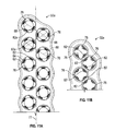
- FIG. 11A is a partially cutaway, top plan view of the bone plate of FIG. 8 .
- FIG. 11B is a partially cutaway, top plan view of another embodiment of a bone plate constructed in accordance with the inventive concepts disclosed herein.
- FIG. 12 is a posterior, perspective view of the bone plate of FIG. 8 shown connected to a plurality of vertebrae along one posterior side of the vertebrae.
- FIG. 13A is a top plan view of another embodiment of a bone plate constructed in accordance with the inventive concepts disclosed herein.
- FIG. 13B is a top plan view of another embodiment of a bone plate constructed in accordance with the inventive concepts disclosed herein.
- FIG. 14 is a top plan view illustrated the bone plate of FIG. 12 nested with the bone of FIG. 13 .
- FIG. 15 is a top plan view of another embodiment of a bone plate constructed in accordance with the inventive concepts disclosed herein.
- FIG. 16 is a top plan view of another embodiment of a bone plate constructed in accordance with the inventive concepts disclosed herein.
- FIG. 17 is a top plan view of another embodiment of a bone plate constructed in accordance with the inventive concepts disclosed herein.
- FIG. 18 is a side elevational view of another embodiment of a bone plate constructed in accordance with the inventive concepts disclosed herein.
- FIG. 19 is a top perspective view of another embodiment of a bone plate constructed in accordance with the inventive concepts disclosed herein.
- FIG. 20 is a top perspective view of another embodiment of a bone plate constructed in accordance with the inventive concepts disclosed herein.
- FIG. 21 is a top perspective view of another embodiment of a bone plate constructed in accordance with the inventive concepts disclosed herein.
- FIG. 22A is a top plan view of another embodiment of a bone plate constructed in accordance with the inventive concepts disclosed herein having a rod portion incorporated therein.
- FIG. 22B is an end elevational view of the bone plate of FIG. 22A .
- FIG. 23A is a perspective view of a pair of the bone plates of FIG. 22A shown connected to the posterior side of a plurality of vertebra and interconnected with a cross-linking connector and showing a lamina connector connected to one of the bone plates.
- FIG. 23B is a perspective view of another embodiment pair of bone plates shown connected to the posterior side of a plurality of vertebra and interconnected with another embodiment of a cross-linking connector and showing another embodiment of a lamina connector connected to one of the bone plates.
- FIG. 23C is an end elevational view of a portion of the bone plate of FIG. 8 shown with a linking connector connected thereto.
- FIG. 23D is a perspective view of the linking connector of FIG. 23C shown connected to the bone plate of FIG. 8 .
- FIG. 24 is a perspective view of another embodiment of a bone plate constructed in accordance with the inventive concepts disclosed herein having a rod portion incorporated therein.
- FIG. 25A is a perspective of another embodiment of a bone plate constructed in accordance with the inventive concepts disclosed herein.
- FIG. 25B is an end elevational view of the bone plate of FIG. 25A .
- FIG. 25C is an end elevational view of the bone plate of FIG. 8 shown with a bone graft ridge connected thereto.
- FIG. 26 is an end elevational view of another embodiment of a bone plate constructed in accordance with the inventive concepts disclosed herein.
- FIG. 27 is a lower perspective view of another embodiment of a bone plate constructed in accordance with the inventive concepts disclosed herein having bosses formed thereon for engagement with an adjacent bone plate.
- FIG. 28 is a perspective view of another embodiment of a bone plate constructed in accordance with the inventive concepts disclosed herein.
- FIG. 29A is a perspective view of another embodiment of a bone plate constructed in accordance with the inventive concepts disclosed herein.
- FIG. 29B is a perspective view of a portion of another version of the bone plate of FIG. 29A .
- FIG. 30 is a perspective view of a portion of another embodiment of a bone plate constructed in accordance with the inventive concepts disclosed herein.
- FIG. 31A is a perspective view of another embodiment of a pair of bone plates constructed in accordance with the inventive concepts disclosed herein.
- FIG. 31B is a perspective view illustrating the bone plates of FIG. 29A connected to the C1 and C2 vertebrae.
- FIG. 32A is a perspective view of another embodiment of a pair of bone plates constructed in accordance with the inventive concepts disclosed herein.
- FIG. 32B is a perspective view illustrating the bone plates of FIG. 30A connected to the C1 and C2 vertebrae.
- FIG. 33A is a perspective view of another embodiment of a pair of bone plates constructed in accordance with the inventive concepts disclosed herein.
- FIG. 33B is a perspective view illustrating the bone plates of FIG. 31A connected to the C1 and C2 vertebrae.
- FIG. 34A is an exploded, perspective view of another embodiment of a bone plate constructed in accordance the inventive concepts disclosed herein.
- FIG. 34B is a perspective view of the bone plate of FIG. 34A .
- FIG. 34C is a sectional view of the bone plate of FIG. 34B .
- FIG. 35A is an elevational view of an embodiment of a post.
- FIG. 35B is an elevational view of another embodiment of a post.
- a typical cervical vertebra 10 is shown in a superior view in FIG. 1A ; two adjacent cervical vertebrae 10 are shown in a lateral view in FIG. 1B ; and the cervical vertebrae are shown from a posterior view in FIG. 2 .
- the spinal cord (not shown) is housed within a central canal 12 that runs the length of the spinal column and is protected along the posterior side of the spinal column by a bony arch, or roof, made up of a pair of lamina 14 and a rearward (dorsally) and downwardly extending portion called the spinous process 16 located between the two laminae 14 .
- the portions of the vertebrae 10 which define the anterior portion of the spine comprise cylindrically shaped bone portions which are stacked one on top of the other. These portions of the vertebrae 10 are referred to as vertebral bodies 20 and are separated from each other by intervertebral discs 22 which provide a cushioning effect between the vertebrae 10 .
- the lateral masses 18 comprise a pair of bone bridges which couple the anterior vertebral body 20 to the laminae 14 of the same vertebra 10
- FIGS. 3-7B a posterior vertebral plating system 30 constructed in accordance with the inventive concepts disclosed herein is shown. Although intended for use primarily in the cervical portion of the spine, it should be understood that the posterior vertebral plating system 10 may be used on any boney structure of the spine, including lumbar, thoracic, and sacral, and the plating system 10 can be used in any direction, e.g., posterior, anterior, or lateral.
- the posterior vertebral plating system 30 includes a bone plate 32 and a plurality of attachment members 34 .
- attachment member is intended to refer to any member that may be used to attach a bone plate to a vertebral bone surface, including, but not limited to, screws, clamps, wire, compression screws, locking screws, tacks, pins, nails, studs, rivets, fasteners, or other such devices known to persons having ordinary skill in the art.
- the bone plate 32 is intended to stabilize multiple vertebrae. To this end, the bone plate 32 has a length dimensioned to extend along the posterior side of at least two vertebrae. It will be appreciated that the length of the bone plate 32 may be varied depending on the number of vertebrae to be stabilized. Because the bone plate 32 is intended to be fixed to boney structures of the posterior side of vertebrae (e.g., lateral mass, lamina), the plate 32 has a width and shape that allows the bone plate 32 to be positioned over the boney structures of the posterior side of adjacent vertebrae. In one embodiment, the bone plate 32 may have an overall width in a range from about 8 mm to about 14 mm, but more desirably, less than about 12 mm.
- the width of the bone plate 32 may be varied or curved or contoured along one side such that the bone plate 32 is configured to have a plurality of nodes 36 which define recesses 38 between each of the nodes 36 to reduce the outer contour and size of the bone plate 32 .
- the bone plate 32 may have at least one minor width 40 at a most narrow portion and at least one major width 42 at a widest portion.
- the minor width 40 may be approximately 5 mm and the major width 42 in a range of approximately 9 mm to 12 mm.
- the reduced width portion between each of the nodes 36 provides an area of reduced material for bending of the bone plate 32 as may be required by the spinal anatomy, as well as provides for better visualization of the boney surface below the bone plate 32 .
- the bone plate 32 has a thickness 44 , which may be in a range including, but not limited to, about 1 mm to about 4 mm, for example.
- the bone plate 32 has an upper surface 46 and a lower surface 48 .
- the bone plate 32 can include a rounded upper edge 50 to reduce irritation of surrounding tissue.
- the rounded upper edge 50 reduces the amount of trauma or irritation that would be experienced by the surrounding soft tissue.
- the lower surface 48 of the bone plate 32 may be configured to conform to the contour of the vertebral bodies at each of the instrumented levels of the spine.
- the lower surface 48 can be provided with a textured surface 52 ( FIG. 4B ) which may include a variety of geometric shapes and/or protrusions, such as spikes, or other features, such as ridges, posts, pockets, or be treated such as bead blasted or acid etched to enhance its grip on the vertebral body.
- the bone plate 32 may also have a longitudinal and/or transverse curvature to match the corresponding attachment surface (e.g., the curve of the spine).
- the bone plate 32 has a plurality of holes 56 which extend through the bone plate 32 from the upper surface 46 through the lower surface 48 .
- the holes 56 are dimensioned and arranged relative to one another so that more than one of the holes 56 is positionable or alignable over the posterior boney structures, such as the lateral mass or lamina, of each vertebra to define a plurality of fixation points per vertebra.
- the holes 56 may be arranged in a variety of ways to provide multiple points of fixation while maintaining the structural strength and rigidity of the bone plate 32 . FIGS.
- FIGS. 4A and 4B illustrate one exemplary embodiment of a hole pattern where the holes 56 are arranged in a plurality of groups of holes 58 a - 58 e (corresponding with one of the nodes 36 ) in such a way that at least two to three of the holes 56 is positionable over a single vertebra to define a plurality of fixation points per vertebra.
- the holes 56 are shown to be arranged in groups of three holes 58 a - 58 e with the holes 56 in each group being arranged in a triangular pattern.
- the holes 56 may be arranged in at least two longitudinal rows of holes 56 along the length of the bone plate 32 with the holes 56 of one longitudinal row of holes being staggered and nested relative to the holes 56 of the other longitudinal row of holes 56 .
- Each group of three holes 58 a - 58 e of holes 56 may be arranged where each laterally adjacent pair of holes is spaced substantially an equal distance and each laterally adjacent pair of holes angled relative to one another in a range from about 30 degrees to about 50 degrees relative to the longitudinal axis of the bone plate 32 so as to result in an overlap of laterally adjacent holes 56 along a longitudinal axis of not more than about 20% (e.g., approximately 10%) of the area of the holes 56 so as to permit longitudinally adjacent holes 56 to remain spaced to align with the lateral mass of the vertebra. Accordingly, it should be apparent that each pair of longitudinally adjacent holes is spaced a greater distance than the laterally adjacent holes.
- the holes 56 may have a diameter to accommodate a screw having an outer diameter in a range from about 1.5 mm to about 3.0 mm (e.g., approximately 2.7 mm), each laterally adjacent pair of holes may be spaced a lateral distance (center to center) in a range from about 2.0 mm to about 4.0 mm (e.g., approximately 2.9 mm) and a longitudinal distance (center to center) in a range of from about 3.0 mm to about 5.0 mm (e.g., approximately 3.5 mm), and each longitudinally adjacent pair of holes may be spaced a longitudinal distance (center to center) in a range from about 6.0 mm to about 8.0 mm (e.g., approximately 7.0 mm) resulting in a bone plate with a width less than 10 mm and a three hole pattern that provides a ratio of hole area/plate area (footprint) in a range of from about 40% to about 60% (e.g., approximately 47%).
- each laterally adjacent pair of holes may be spaced a
- the bone plate 32 depicted in FIGS. 6A and 6B includes five nodes and five groupings of holes, and the bone plate 32 has a length so that the bone plate 32 can be engaged to five cervical vertebrae of the spine.
- the bone plate 32 can be configured to fix any number of vertebrae depending upon the length of the bone plate 32 and the number and arrangement of attachment members.
- each group of holes 58 a - 58 e is spaced apart from the adjacent group of holes a distance which is generally greater than the distance between laterally adjacent holes 56 .
- the bone plate may be provided with transverse grooves 60 in one of the upper surface 46 and the lower surface 48 , or both the upper surface 46 and the lower surface 48 .
- the holes 56 may be formed entirely perpendicular to the plane of the bone plate 32 , or may be offset in the general direction which screw angulation is desired to aid in minimizing the risk of comprising vascular and neural structures.
- the holes 56 may be laterally outwardly angled, e.g., at an angle of approximately 10 to 30 degrees of lateral outward angulation.
- each hole 56 is shown to be threaded to receive one of the attachment members 34 .
- any thread configuration may be used, or the holes 56 may even be smooth or non-threaded.
- each hole 56 is illustrated as being threaded to receive an attachment member 34 in the form of a variable angle locking screw 34 a .
- the holes 56 have a plurality of columns of threads 62 spaced apart to define a plurality of non-threaded recesses 64 . In the embodiment illustrated herein, each of the holes 56 has four columns of threads 62 .
- the columns of threads 62 are arranged around the inner surface of each of the holes 56 for engaging threads on a head of locking and variable-angle locking bone screws.
- Conventional locking screws engage the bone plate 32 coaxially with the central axis of the hole of the bone plate 32 .
- Variable-angle locking screws can engage the bone plate 32 at a selected angle within a range of selectable angles relative to the central axis of hole of the bone plate 32 .
- An example of a variable angle locking screw 34 a is illustrated in FIG. 3 .
- variable-angle locking screw 34 a has a head 34 b which is at least partially spherical and a thread 34 c which has a profile that follows the arc-shaped radius of curvature of the spherical portion of the head 34 b .
- Variable angle locking screws are well known in the art such as disclosed in U.S. 2008/0140130 filed by Chan et al., for example, which is hereby expressly incorporated herein by reference.
- variable angle capability of the variable angle locking screw 34 a allows a surgeon to place the variable angle locking screw 34 a within the vertebra at any angle within defined angulation limits.
- the variable angle locking screw 34 a provides greater flexibility than does a fixed angle screw.
- the holes 56 may be provided with a flange 66 extending between adjacent columns of threads 62 hole near the lower surface 48 of the bone plate 32 in such a way that the flange 66 functions to obstruct the attachment member 34 , such as the variable angle screw 34 a , from being driven too deeply into the vertebra and thereby limit the risk of injury to patients.
- the flanges 66 are formed coextensively with respect to the lower most thread of the columns of threads 62 so as to engage with the threads 34 c of the head 43 b of the variable angle locking screw 34 a upon the head 34 b of the variable angle locking screw 34 a being fully driven into the hole 56 and thereby provide an obstruction to the variable angle locking screw 34 a .
- the attachment member 34 may alternatively, or in addition to, have a flange element or stop member that contacts a portion of the bone plate 32 to limit the depth or distance which the attachment element 34 may be inserted into the bone.
- the holes 56 are necessarily positioned relatively close to one another. As such, the strength of the bone plate 32 can be compromised along the narrowest portions of the bone plate 32 . As described above, one of those narrow portions is generally located between laterally adjacent holes 56 . To increase the strength in these areas, at least one of the columns of threads 62 a of one of the holes 56 of a pair of laterally adjacent holes intersects a line 68 ( FIG. 4A ) extending between the axes of the holes 56 of the pair of laterally adjacent holes 56 . Moreover, in certain arrangements, such as shown in FIG.
- one of the columns of threads 62 a of each of the holes 56 of a pair of laterally adjacent holes intersects and is aligned with the line 68 extending between the axes of the holes 56 of the pair of laterally adjacent holes 56 , such that the columns of threads 62 function to provide a thicker area between two laterally adjacent holes than would exist if the non-threaded recesses 64 were aligned.
- the thicker area provides the advantage of increased strength of the bone plate 32 .
- the posterior spinal fixation system 30 is illustrated as being connected to the posterior side of a plurality of vertebrae 10 with the bone plates 32 extending along the posterior side of five vertebrae 10 adjacent the lateral masses 18 of each of the vertebra 10 and the holes 56 being spaced in such a way that a plurality of holes 56 is positioned over the lateral mass 18 of each of the vertebra 10 to define a plurality of fixation points to each of vertebra 10 .
- the attachment members 34 are inserted through selected holes 56 and into the lateral mass 18 of a corresponding vertebra 10 to fix the bone plate 32 to the vertebrae 10 . It will be appreciated that the user can elect not to insert an attachment member 34 into selected holes.
- the bone plate 32 a is similar structure and function to the bone plate 32 described above.
- the bone plate 32 a is intended to stabilize multiple vertebrae.
- the bone plate 32 a has a length dimensioned to extend along the posterior side of at least two vertebrae. It will be appreciated that the length of the bone plate 32 a may be varied depending on the number of vertebrae to be stabilized.
- the bone plate 32 a is intended to be fixed to boney structures of the posterior side of vertebrae (e.g., lateral mass, lamina), the bone plate 32 a has a width and shape that allows the bone plate 32 a to be positioned over the boney structures of the posterior side of adjacent vertebrae.
- the bone plate 32 a may have a width less than about 15 mm, but more desirably, less than about 12 mm.
- the bone plate 32 a has an upper surface 70 and a lower surface 72 .
- the bone plate 32 can include a rounded upper edge 74 to reduce irritation of surrounding tissue.
- the rounded upper edge 74 reduces the amount of trauma or irritation that would be experienced by the surrounding soft tissue.
- the lower surface 72 of the bone plate 32 a may be configured to conform to the contour of the vertebral bodies at each of the instrumented levels of the spine.
- the lower surface 48 can be provided with a textured surface such that described above in reference to FIG.
- the bone plate 32 a may also have a longitudinal and/or transverse curvature to match the corresponding attachment surface (e.g., the curve of the spine).
- the bone plate 32 a has a plurality of holes 76 which extend through the bone plate 32 a from the upper surface 70 through the lower surface 72 .
- the holes 76 may be entirely perpendicular to the plane of the bone plate 32 a , or may be offset in the general direction which screw angulation is desired.
- the holes 76 may be laterally outwardly angled, e.g., at an angle of approximately 10 to 30 degrees of lateral outward angulation.
- the holes 76 are dimensioned and arranged relative to one another so that more than one of the holes 76 is positionable or alignable over the boney structure, such as a lateral mass or lamina, of each vertebra to define a plurality of fixation points per vertebra.
- the holes 76 may be arranged in a variety of ways to provide multiple points of fixation while maintaining the structural strength and rigidity of the bone plate 32 a .
- FIGS. 8 , 9 , and 11 A illustrate one embodiment of a hole pattern where the holes 76 are arranged in two longitudinal rows of holes 76 along the length of the bone plate 32 a with the holes 76 of one longitudinal row of holes being staggered relative to the holes 76 of the other longitudinal row of holes 76 .
- Each of the holes 76 may be arranged where each laterally adjacent pair of holes 76 are spaced substantially a first distance, and each pair of longitudinally adjacent holes are spaced substantially a second distance where the second distance is greater than the first distance and each laterally adjacent pair of holes are angled relative to one another in a range from about 45 degrees to about 65 degrees (e.g., approximately 57 degrees) relative to the longitudinal axis of the bone plate 32 a.
- the holes 76 While shown as being staggered, are not overlapped with one another along a longitudinal axis. However, an innermost point of each of the holes 76 may be aligned with a longitudinal axis 77 to minimize the width of the plate.
- the holes 56 may have a diameter to accommodate a screw having an outer diameter in a range from about 1.5 mm to about 3.0 mm.
- each laterally adjacent pair of holes may be spaced a lateral distance in a range from about 3.0 mm to about 5.0 mm (e.g., approximately 4.2 mm) and a longitudinal distance in a range of from about 2.0 mm to about 5.0 mm (e.g., approximately 2.8 mm), and each longitudinally adjacent pair of holes may be spaced a longitudinal distance in a range from about 4.0 mm to about 7.0 mm (e.g., approximately 5.5 mm) resulting in a bone plate with a width less than 12 mm and a four hole pattern providing a ratio of hole area/plate area (footprint) in a range of from about 40% to about 60% (e.g., approximately 49%).
- the bone plate 32 a can be configured to fix several vertebrae depending upon the size/length of the bone plate 32 a and the number and arrangement of attachment members.
- the bone plate 32 a depicted in FIG. 8 includes nine holes 76 in each longitudinal row, and the bone plate 32 a has a length so that the bone plate 32 a can be attached to five cervical vertebrae of the spine.
- each of the holes 56 is illustrated as being threaded to receive an attachment member 34 in the form of a variable angle locking screw 34 a ( FIG. 3 ).
- the holes 76 have a plurality of columns of threads 82 spaced apart to define a plurality of non-threaded recesses 84 . In the embodiment illustrated herein, each of the holes 76 has four columns of threads 82 .
- the columns of threads 82 are arranged around the inner surface of each of the holes 76 for engaging threads on a head of locking and variable-angle locking bone screws.
- Conventional locking screws engage the bone plate 32 a coaxially with the central axis of the hole of the bone plate 32 a .
- Variable-angle locking screws can engage the bone plate 32 a at a selected angle within a range of selectable angles relative to the central axis of hole of the bone plate 32 a.
- the holes 56 may be provided with a flange 86 extending between adjacent columns of threads 82 hole near the lower surface 72 of the bone plate 32 a in such a way that the flange 86 functions to obstruct the attachment member 34 , such as the variable angle screw 34 a , from being driven too deeply into the vertebra and thereby limit the risk of injury to patients.
- the flanges 86 are formed coextensively with respect to the lower most tooth of the columns of threads 82 so as to engage with the threads 34 c of the head 43 b of the variable angle locking screw 34 a upon the head 34 b of the variable angle locking screw 34 a being fully driven into the hole 76 and thereby provide an obstruction to the variable angle locking screw 34 a.
- the holes 76 are necessarily positioned relatively close to one another. As such, the strength of the bone plate 32 a can be compromised along the narrowest portions of the bone plate 32 a . As described above, one of those narrow portions is generally located between laterally adjacent holes 76 . To increase the strength in these areas, at least one of the columns of threads 82 a of one of the holes 76 of a pair of laterally adjacent holes intersects a line 88 ( FIG.
- FIG. 11B illustrates a modified version of the bone plate 32 a illustrating the holes 76 arranged in such a manner that the spacing between laterally adjacent holes is minimized whereby the opposing pairs of columns of threads 82 generally provide the structure between each laterally adjacent pair of holes 76 .
- FIG. 12 shows the bone plate 32 a connected to the posterior side of a plurality of vertebrae 10 with the bone plates 32 a extending along the posterior side of four vertebrae 10 adjacent the lateral masses 18 of each of the vertebrae 10 and the holes 76 being spaced in such a way that a plurality of holes 76 is positioned over the lateral mass 18 of each of the vertebrae 10 to define a plurality of fixation points to each of vertebrae 10 .
- the attachment members 34 are inserted through selected holes 76 and into the lateral mass 18 of a corresponding vertebra 10 to fix the bone plate 32 a to the vertebrae 10 .
- FIG. 13A shows another embodiment of a bone plate 32 b constructed in accordance with the inventive concepts disclosed herein.
- the bone plate 32 b is similar to the bone plate 32 a , except that the bone plate 32 b has a plurality of holes 90 arranged in two longitudinal rows with the holes 90 of each row positioned directly laterally of a hole 90 in the other row.
- the holes 90 are sized and spaced apart from one another such that two or more of the holes 90 are positionable or alignable over the lateral mass of a single vertebra to define a plurality of fixation points per vertebra.
- the bone plate 32 b is illustrated as having a perimeter edge 92 extending between the upper surface and the lower surface which is configured to substantially conform to the contour of the holes 90 of the of the bone plate 32 b to define a plurality of nodules and recesses.
- FIG. 13B shows a version of a bone plate 32 c constructed in accordance with the inventive concepts disclosed herein.
- the bone plate 32 c is similar to the bone plate 32 b , except that the bone plate 32 b has a single longitudinal row of holes 94 .
- the holes 94 are sized and spaced apart from one another such that at least two of the holes 94 are positionable or alignable over the lateral mass or lamina of a single vertebra to define a plurality of fixation points per vertebra.
- the bone plate 32 c has a perimeter edge 96 extending between the upper surface and the lower surface which is configured to substantially conform to the contour of the holes 94 of the of the bone plate 32 c to define a plurality of nodules and recesses.
- FIG. 14 illustrates the bone plate 32 b nested or engaged with the bone plate 32 c along one side of corresponding edges of the bone plates 32 b and 32 c .
- the bone plate 32 b can be attached to the lateral masses, while the bone plate 32 c can be attached to the corresponding lamina.
- FIG. 15 illustrates another embodiment of a bone plate 32 d constructed in accordance with the inventive concepts disclosed herein.
- the bone plate 32 d is similar to the bone plate 32 b . That is, the bone plate 32 d has a plurality of holes 98 arranged in two longitudinal rows with the holes 98 of each row positioned directly laterally of a hole 98 in the other row.
- the holes 98 are sized and spaced apart from one another such that at least two of the holes 98 are positionable or alignable over the lateral mass or lamina of a single vertebra to define a plurality of fixation points per vertebra.
- the bone plate 32 d is illustrated as having a perimeter edge 200 extending between the upper surface and the lower surface which is substantially straight or non-contoured.
- FIG. 16 illustrates another embodiment of a bone plate 32 e constructed in accordance with the inventive concepts disclosed herein.
- the bone plate 32 e is similar to the bone plate 32 illustrated in FIG. 3 , except that the bone plate 32 e is shown to have vertically-oriented grooves 202 extending along either or both outer edges from the upper surface to the lower surface to facilitate bending of the bone plate 32 e along a coronal plane.
- FIG. 17 illustrates another embodiment of a bone plate 32 f constructed in accordance with the inventive concepts disclosed herein.
- the bone plate 32 f is similar to the bone plate 32 illustrated in FIG. 3 , except that the bone plate 32 f has a plurality of groups of holes 204 a - 204 f and the distance which the groups of holes 204 a - 204 f are spaced from one another increases sequentially from one of the bone plate 32 f to the other end.
- the groups of holes 204 a - 204 f may be spaced at intervals of 13 mm, 14 mm, 15 mm, 16 mm, and 17 mm.
- FIG. 18 illustrates another embodiment of a bone plate 32 g constructed in accordance with the inventive concepts disclosed herein.
- the bone plate 32 g is similar to the bone plate 32 illustrated in FIG. 3 , except that the bone plate 32 g is tapered along a longitudinal axis such that one end of the bone plate 32 g has a minor thickness 206 which is less thick than the other end which has a major thickness 208 .
- the minor thickness 206 may be 1.85 mm and the major thickness 208 may be 2.65 mm.
- FIGS. 19-21 illustrate bone plates 32 h , 32 i , and 32 j constructed in accordance with the inventive concepts disclosed herein.
- the bone plate 32 h , 32 i , and 32 j are configured to be bent along a longitudinal axis.
- the bone plate 32 h has longitudinal groove 210 to facilitate bending of the bone 32 h so as to define a lateral mass plate portion 212 and a lamina plate portion 214 .
- the lateral mass plate portion 212 and the lamina plate portion 214 each have a plurality of holes 216 arranged in two longitudinal rows such the lateral mass plate portion 212 is attachable to the lateral masses of the corresponding vertebrae and the lamina plate portion 214 is attachable to the lamina of the corresponding vertebra with suitable attachment members.
- the bone plate 32 i is similar to the bone plate 32 h except the bone plate 32 i has a lamina plate portion 218 which has a plurality of tabs 219 which are individually bendable relative to the other tabs 219 .
- Each tab 219 is shown as having two holes 220 for receiving attachment members.
- the bone plate 32 j is similar to the bone plate 32 i , except the bone plate 32 j has a lateral mass plate portion 221 shown to have a plurality of holes 222 arranged in a single longitudinal row for receiving attachment members.
- FIGS. 22A , 22 B, and 23 A another embodiment of a bone plate 32 k constructed in accordance with the inventive concepts disclosed herein is illustrated.
- the bone plate 32 k is shown as being similar to the bone plate 32 a described above except that the bone plate 32 k has a longitudinal edge 224 and a rod portion 226 formed along the inner longitudinal edge 224 .
- the rod portion 226 may serve as an attachment point for auxiliary implements.
- the rod portion 226 may be used as a point of attachment for a cross-linking connector 228 .
- the cross linking connector 228 may include a rod portion 230 and a rod engaging portion 232 formed on each end of the rod portion 230 .
- the rod engaging portions 232 may be in the form of a C-shaped clamp mateable with the rod portion 230 of the bone plate 32 k and a securement member, such as a set screw 233 .
- the rod portion 230 has a length (or may configured for selective translation) so that the rod portion 230 extends from one side of a vertebra to an opposing side of the vertebra when one of the rod engaging portions 232 is engaged with the rod portion 226 of the bone plate 32 k and the bone plate 32 k is connected to the lateral masses of a plurality of vertebrae and the other rod engaging portions 232 is engaged with the rod portion 226 of another bone plate 32 k and the other bone plate 32 k is connected to the opposing lateral masses of the vertebrae.
- the rod portion 226 may also be used as a point of attachment for a lamina connector 234 for fixing an arch during a laminoplasty procedure.
- the lamina connector 234 may have a plate portion 236 and a rod engaging portion 238 .
- the rod engaging portion 238 may be in the form of a C-shaped clamp mateable with the rod portion 230 of the bone plate 32 k and a securement member, such as a set screw 233 .
- the plate portion 236 has a hole for receiving an attachment member, such as a screw 242 .
- the plate portion 236 may be configured to for translation in a manner well known in the art.
- the plate portion 236 is positionable over a lamina of a vertebra and when the rod engaging portion 238 is engaged with the rod portion 236 of the bone plate 32 k and the bone plate 32 k is connected to the lateral masses of a plurality of vertebrae.
- FIG. 23B illustrates alternative embodiments of a cross linking connector 228 a and a lamina connector 234 a which are similar to the cross linking connector 228 and the lamina connector 234 , respectively, except that the cross linking connector 228 a and the lamina connector 234 a are configured to be attached to a bone plate, such as the bone plate 32 a , employing the holes 76 of the bone plate 32 a used for fixing the bone plate 32 a to vertebra or to alternative holes (not shown) which may be provided in the bone plate for attaching auxiliary implements thereto.
- a bone plate such as the bone plate 32 a
- the cross linking connector 228 a includes a rod portion 241 and a plate portion 242 formed on each end of the rod portion 241 .
- the plate portions 242 are shown as being provided with a plurality of holes which are alignable with a plurality of holes 76 of the bone plates 32 a such that the plate portions 244 may be attached to the upper surface of the bone plates 32 a with a plurality of attachment members, such as screws 246 .
- the lamina connector 234 a may include a first plate portion 248 and a second plate portion 250 where the second plate portion 250 is similar in construction and function to the plate portion 242 described in reference to the cross linking connector 228 a.
- FIGS. 23C and 23D illustrate an embodiment of a linking connector 228 b which is similar to the cross linking connector 228 a , except that the linking connector 228 b includes plate portion 241 a and a rod receiving member 242 a .
- the plate portion 241 a is provided with a plurality of holes which are alignable with a pair of holes 76 of the bone plate 32 a such that the plate portion 241 a may be attached to the upper surface of the bone plate 32 a with a plurality of attachment members, such as screws 246 .
- the rod receiving member 242 a When the plate portion 241 a is connected to the bone plate 32 a , the rod receiving member 242 a is oriented to receive a rod 244 which is longitudinally extended along the spine to be positioned so as to be connectable to other implements implanted in other vertebrae to which the bone plate 32 a is not directly attached, such as one or more polyaxial screws.
- the rod 244 may be secured in the rod receiving member 241 a with an attachment member, such as a set screw 249 .
- FIG. 24 illustrates another embodiment of a bone plate 32 j constructed in accordance with the inventive concepts disclosed herein.
- the bone plate 32 j is similar to the bone plate 32 k described above, except the bone plate 32 j has a rod portion 226 a formed along a longitudinal edge of the bone plate 32 j such that the rod portion 226 a may serve as an attachment point for auxiliary implements.
- the rod portion 226 a further has a rod extension portion 252 which extends a distance beyond at least one end of the bone plate 32 k so as to be connectable to other implements implanted in other vertebrae to which the bone plate 32 j is not directly attached, such as one or more polyaxial screws.
- the rod extension portion 252 may be configured to be positioned in a rod receiving head of polyaxial screw assembly in a manner similar to the way a spinal rod (not shown) would be positioned in a rod receiving head of a polyaxial screw assembly. It should be appreciated that the length of the rod extension portion 252 may be varied during manufacture or customized prior to attachment to a patient.
- FIGS. 25A and 25B another embodiment of a bone plate 32 m constructed in accordance with the inventive concepts disclosed herein is illustrated.
- the bone plate 32 m is illustrated as being similar in construction to the bone plate 32 a described above, except the bone plate 32 m has an outer longitudinal edge 254 with a bone graft ridge 256 extending upwardly and outwardly from the outer longitudinal edge 254 of the bone plate 32 m .
- the bone graft ridge 256 functions to define a pocket or void 258 in cooperation with the surface of the vertebrae so that biologic material may be packed in the pocket 258 to facilitate the formation of a graft between two vertebrae.
- biologic material can include, but is not limited to, medicine, human tissue, animal tissue, synthetic tissue, human cells, animal cells, synthetic cells, and the like.
- FIG. 25C illustrates another version of a bone graft ridge 256 a which is formed by a separate piece which may be connected to a bone plate, such as the bone plate 32 a , in any suitable fashion, such as with screws (now shown).
- FIG. 26 illustrates another embodiment of a bone plate 32 n constructed in accordance with the inventive concepts disclosed herein.
- the bone plate 32 n is similar to the bone plates described above, except the bone plate 32 n has a pair of flanges 260 a and 260 b extending downwardly from the lower surface thereof along an inner longitudinal edge 262 and an outer longitudinal edge 264 so as to define a pocket 266 in which biologic material may be packed to facilitate the formation of a graft between two vertebrae.
- FIG. 27 illustrates another embodiment of a bone plate 32 o that is similar to the plates discussed above, except that the bone plate 32 o is provided with a plurality of protrusions 267 extending from a lower side 268 of the bone plate 32 o near one end thereof.
- the protrusions 267 are configured and arranged to align with and fit in a group of holes of another bone plate in such a way that the two plates may be interlocked with one another.
- the bone plate 32 o may be contoured so that the bone plate 32 o may be positioned on another bone plate in an overlapping relationship, while permitting the bone plate 32 o to be attached to vertebrae in the manner discussed above with attachment members 34 .
- FIG. 28 illustrates yet another embodiment of a bone plate 32 q constructed in accordance with the inventive concepts disclosed herein.
- the bone plate 32 q includes a first plate portion 270 and a second plate portion 272 .
- the first plate portion 270 and the second plate portion 272 are illustrated as being similar in configuration to the bone plate 32 a described above.
- the first plate portion 270 is longitudinally aligned with the second plate portion 272 , and the first plate portion 270 is pivotally connected to the second plate portion 272 .
- first plate portion 270 may be pivotally connected to the second plate portion 272 via a locking hinge 274 to allow the first plate portion 272 and the second plate portion 274 to be fixed in a desired angular relationship relative to one another, whether about a single axis or multiple axes, particularly when used for occipital-cervical fusion or deformity correction.
- FIG. 29A is a bottom perspective view of another embodiment of a bone plate 32 r constructed in accordance with the inventive concepts disclosed herein is illustrated.
- the bone plate 32 r is illustrated as being similar in construction to the bone plate 32 a , except the bone plate 32 r is provided with a hook 276 extending substantially normal to the longitudinal axis of the bone plate 32 r .
- the hook 276 is configured to be received on the posterior arch of the C1 vertebra when the bone plate 32 r is connected to the adjacent vertebrae of the spine as discussed above.
- the hook 276 may be formed at various angles relative to the longitudinal axis of the bone plate 32 r to be received at selected positions on the arch of the C1 vertebra. As shown in FIG.
- the bone plate 32 r may be further provided with a retaining groove 278 formed on an outer surface of the hook 276 to retain a cable or wire (not shown) which may be extended about the hook 276 and the ring of the C1 vertebra to further hold the hook 276 in place on the ring.
- FIG. 30 illustrates another version of a bone plate 32 s which is similar to the bone plate 32 r except the bone plate 32 s includes a platform 280 extending substantially normal to the longitudinal axis of the bone plate 32 s .
- the platform 280 is configured to be positioned on the ring of the C1 vertebra when the bone plate 32 s is connected to the adjacent vertebrae of the spine as discussed above.
- the hook platform 280 may be formed at various angles relative to the longitudinal axis of the bone plate 32 s to be received at selected positions on the ring of the C1 vertebra.
- the platform 280 may be provided with a retaining groove 282 and a hole 284 retaining a cable (not shown) which may be extended about the through the hole 284 , about the platform 280 along the retaining groove 282 , and about the ring of the C1 vertebra to hold the platform 280 in place on the ring.
- FIGS. 31A and 31B another embodiment of a pair of bone plate 32 t and 32 tt constructed in accordance with the inventive concepts disclosed herein is illustrated.
- the bone plates 32 t and 32 tt are identical in construction with the exception that the bone plate 32 tt is a mirror image of the bone plate 32 t . Therefore, only the bone plate 32 t will be described in detail below.
- the bone plate 32 t is intended to fuse or stabilize multiple vertebrae, more specifically the C1 and C2 vertebrae.
- the bone plate 32 t is configured and dimensioned to extend along the posterior side of at least the C1 vertebra and the C2 vertebra, and particularly, the bone plate 32 r is configured to extend from a posterior ring 290 of a C1 vertebra 292 to a lamina 294 of a C2 vertebra 296 . It will be appreciated that the length of the bone plate 32 t may be varied depending on the number of vertebrae to be stabilized beyond the C2 vertebra.
- the bone plate 32 t has an upper surface 298 and a lower surface 300 .
- the lower surface 300 can be provided with a textured surface such that described above in reference to FIG. 4B which may include a variety of geometric shapes and/or protrusions, such as spikes, or other features, such as ridges, posts, pockets, or be treated such as bead blasted or acid etched to enhance its grip on the vertebral body.
- the bone plate 32 t has a spacer portion 302 having a first end 304 and a second end 306 .
- the longitudinal length of the spacer portion 302 generally corresponds to the distance between the ring 290 of the C1 vertebra 292 and the lamina 294 of the C2 vertebra 296 .
- a ring engaging portion 308 extends from the first end 304 of the spacer portion 308 .
- the ring engaging portion 308 is configured to extend along and conform to at least a portion of the ring 290 of the C1 vertebra 292 . More specifically, the ring engaging portion 308 has an arcuate profile such that the ring engaging portion 308 substantially conforms to the contour of the ring 290 of the C1 vertebra 292 .
- the ring engaging portion 308 has a width such that a plurality of holes 310 may be formed in the ring engaging portion 310 in such a way that at least two holes are positionable over the posterior side of the ring 290 of the C1 vertebra 292 .
- the holes 310 may be threaded or non-threaded similar to the holes 56 and 76 discussed above to receive an attachment member, such as attachment members 34 .
- a lamina engaging portion 312 extends from the second end 306 of the spacer portion 302 .
- the lamina engaging portion is configured to extend along and conform to a portion of the posterior side of the C2 vertebra 296 , e.g., the lamina, the lateral mass, or a combination of the lamina and the lateral mass.
- the lamina engaging portion 312 has a flatter profile than the ring engaging portion 308 so that the lamina engaging portion 312 substantially conforms to the contour of the lamina 294 of the C2 vertebra 296 .
- the lamina engaging portion 312 has a width such that a plurality of holes 314 are formed in the lamina engaging portion 312 in such a way that at least two holes are positionable over the lamina 294 of the C2 vertebra 296 .
- the holes 312 may be threaded or non-threaded similar to the holes 56 and 76 discussed above to receive an attachment member, such as attachment members 34 .
- the spacer portion 302 has a width that is less than the width of the ring engaging portion 308 and the width of the lamina engaging portion 312 so as to define a notch or window 316 along an inside edge of the bone plate 32 t .
- the window 316 allows direct visualization of the central canal, as well as facilitates identifying the difference between the bone plate 32 r and 32 rr.
- the holes 310 and 314 extend through the bone plate 32 r from the upper surface 298 through the lower surface 300 .
- the holes 310 and 314 may be entirely perpendicular to the plane of the bone plate 32 t , or may be offset in the general direction which screw angulation is desired.
- the holes 310 and 314 may be laterally outwardly angled, e.g., at an angle of approximately 10 to 30 degrees of lateral outward angulation.
- the holes 310 are dimensioned and arranged relative to one another so that more than one of the holes 310 are positionable or alignable over the ring 290 of the C1 vertebra 292 to define a plurality of fixation points to the C1 vertebra 292
- the holes 314 are dimensioned and arranged relative to one another so that more than one of the holes are positionable or alignable over the lamina 294 of the C2 vertebra 296 to define a plurality of fixation points to the C2 vertebra 296 .
- the holes 310 and 314 may be arranged in a variety of ways to provide multiple points of fixation.
- the bone plate 32 t and the holes 310 and 314 are shown to be sized and spaced is so that at least two of the holes 310 and 314 are positionable over each vertebra to which the bone plate 32 t is to be coupled (considering one side of the spine only and depending on the particular vertebra to which the plate is coupled).
- sizing and spacing of the holes 302 may be varied to achieve a desired number of fixation points.
- the holes 310 and 314 may have a diameter to accommodate a screw having an outer diameter in a range from about 1.5 mm to about 3.0 mm.
- the holes 310 and 314 are shown to be threaded to receive one of the attachment members 34 a .
- any thread configuration may be used, including variable angle locking threads, or the holes 310 and 314 may even be non-threaded or smooth.
- the holes 312 and 314 may be may be provided with flanges, as described above, to limit the extent of insertion of the attachment members 34 .
- FIGS. 32A and 32B another embodiment of a pair of bone plate 32 u and 32 uu constructed in accordance with the inventive concepts disclosed herein is illustrated.
- the bone plate 32 u and 32 uu are identical in construction with the exception that the bone plate 32 uu is a mirror image of the bone plate 32 u . Therefore, only the bone plate 32 u will be described in detail below.
- the bone plate 32 u is intended to fuse or stabilize multiple vertebrae, more specifically the C1 and C2 vertebrae. To this end, the bone plate 32 u is configured and dimensioned to extend along the posterior side of at least the C1 vertebra and the C2 vertebra.
- the bone plate 32 u is configured to extend from the posterior ring 290 of the C1 vertebra 292 to a juncture of the lamina 294 and spinous process 320 of the C2 vertebra 296 . It will be appreciated that the length of the bone plate 32 u may be varied depending on the number of vertebrae to be stabilized.
- the bone plate 32 u is similar to the bone plate 32 t in construction and function, except that the bone plate 32 u includes a translamina engaging portion 322 rather than a lamina engaging portion 312 .
- the translamina engaging portion 322 is configured to extend along and conform to at least a portion of the lamina 296 , a junction 324 of the lamina 296 and the spinous process 320 , and the spinous process 320 .
- the translamina engaging portion 322 has a lamina portion 326 and a spinous process portion 328 which are angled relative to one another to define a junction portion 330 .
- the translamina engaging portion 322 has a width such that a plurality of holes 332 are formed in the translamina engaging portion 322 so that at least two holes are positionable over the combined area of the lamina 296 and the spinous process 320 .
- the translamina engaging portion 322 has at least one hole 332 a located through the bone plate 32 u at the junction portion 330 and oriented in such a way as to permit translaminar screw placement when the translamina engaging portion 322 is positioned on the lamina 296 and spinous process 320 .
- the bone plate 32 v is intended to fuse or stabilize multiple vertebrae, more specifically the C1 and C2 vertebrae.
- the bone plate 32 v is configured and dimensioned to extend along the posterior side of at least the C1 vertebra 292 and the C2 vertebra 296 . More specifically, the bone plate 32 v is configured to extend from the posterior ring 290 of the C1 vertebra 292 to each lamina 294 of the C2 vertebra 292 . It will be appreciated that the length of the bone plate 32 v may be varied depending on the number of vertebrae to be stabilized.
- the bone plate 32 v has an upper surface 338 and a lower surface 340 .
- the lower surface 338 can be provided with a textured surface such that described above in reference to FIG. 4B which may include a variety of geometric shapes and/or protrusions, such as spikes, or other features, such as ridges, posts, pockets, or be treated such as bead blasted or acid etched to enhance its grip on the vertebral body.
- the bone plate 32 v has a spacer portion 342 having a first end 344 and a second end 346 .
- the longitudinal length of the spacer portion 342 generally corresponds to the distance between the ring 290 of the C1 vertebra 292 and the laminae 294 of the C2 vertebra 296 .
- a ring engaging portion 348 extends from the first end 344 of the spacer portion 348 .
- the ring engaging portion 348 is configured to extend along and conform to at least a portion of the ring 290 of the C1 vertebra 292 . More specifically, the ring engaging portion 348 has an arcuate profile such that the ring engaging portion 348 substantially conforms to the contour of the ring 290 of the C1 vertebra 292 .
- the ring engaging portion 348 has a width such that a plurality of holes 350 are formed in the ring engaging portion 348 in such a way that at least two holes are positionable over the posterior side of the ring 290 of the C1 vertebra 292 .
- the holes 350 may be threaded or non-threaded similar to the holes 56 and 76 discussed above to receive an attachment member, such as attachment members 34 .
- a first lamina engaging portion 352 extends from the second end 346 of the spacer portion 342
- a second lamina engaging portion 354 extends from the second end 346 of the spacer portion 342
- the first and second lamina engaging portions 352 and 354 extend from the spacing portion 342 as to define a notch 356 for receiving the spinous process 320 of the C2 vertebra.
- Each of the first and the second lamina engaging portions 352 and 354 has a flatter profile than the ring engaging portion 348 so that the lamina engaging portions 352 and 354 substantially conform to the contour of the respective laminae 294 of the C2 vertebra 296 .
- the lamina engaging portions 352 and 354 each has a width such that a plurality of holes 358 are formed in the lamina engaging portions 352 and 354 so that at least two holes are positionable over each of the lamina 294 of the C2 vertebra 296 .
- the holes 358 may be threaded or non-threaded similar to the holes 56 and 76 discussed above to receive an attachment member, such as attachment members 34 .
- the bone plate 32 w includes a plate portion 360 , having an upper surface 362 , a lower surface 364 , and a plurality of holes 366 extending through the plate portion 360 from the upper surface 362 to the lower surface 364 .
- the plate portion 360 is configured to extend along the posterior side of at least one vertebra adjacent a lateral mass or lamina of the vertebrae and the holes 366 are spaced such that a plurality of holes is positionable over the vertebra to define a plurality of fixation points to the vertebra.
- the bone plate 32 w further has a post 368 extending from the upper surface 362 of the plate portion 360 .
- the post 368 has an enlarged spherical head portion 370 which is received within a bushing 372 so that the post 368 can poly-axial rotate with respect to the bushing 372 .
- the bushing 372 is positioned an inner spherical cavity formed in a rod receiving head 374 .
- the post 368 may be formed integral with the rod receiving head 374 to form a monolithic structure.
- the post may be formed has a separate structure which is adapted to be connected to the plate portion 362 or one of the other bone plates described herein.
- a post 368 a may include a threaded shaft 386 and a spherical head 388 with variable angle locking threads so that the post 368 a is connectable to a bone plate and insertable into bone.
- a post 368 b may include only a spherical head 390 with variable angle locking threads so that the post 368 b is only intended to be connected to a bone plate without providing fixation to bone.
- the rod receiving head 374 has a central passage 376 in which an elongated rod 378 may be seated so as to transversely extend through the central passage 376 .
- the rod 378 may be seated in a saddle 380 positioned about the bushing 372 and secured in the rod receiving head 372 with a threaded locking cap 382 that is threaded to the rod receiving head 374 to lock the rod 378 in place.
- Exemplary embodiments of polyaxial screws include those described in International Patent Application No. PCT/US2008/070670, filed on Jul. 21, 2008, entitled “Polyaxial Bone Fixation Element,” International Patent Application No. PCT/US2006/015692, filed on Apr. 25, 2006, entitled “Bone Anchor with Locking Cap and Method of Spinal Fixation,” and International Patent Application No. PCT/CH1997/00236, filed on Jun. 16, 1997, entitled “Device for Connecting a Longitudinal Support with a Pedicle Screw,” the contents of which are hereby incorporated by reference in their entirety. It should be understood, however, that the bone plate 32 u is not intended to be limited to any particular type of locking cap or polyaxial screw configuration.
- the bone plates described above may be constructed of any suitable biocompatible material which has the structural strength and durability to withstand the cyclical loading associated with long term fixation to the spine.
- Materials which would be suitable for such applications include, but are not limited to, titanium, titanium alloys (e.g., TAN), steel alloys such as stainless steel, tantalum, polymers such as PEEK, reinforced plastics, allograft bone, and other materials that would be suitable in alternative embodiments, such as composites.
- the attachment members may be constructed of a like material whereby the attachments members may be secured to the bone plate after insertion by welding.
- the bone plates can further include one or more bone growth or fusion-promoting elements, such as bone, bone morphogenetic protein (BMP), demineralized bone matrix (DBM), LIM mineralization proteins (LMP), osteogenic pastes, and so forth. It is understood that such fusion-promoting elements are well known by those of ordinary skill in the art.
- BMP bone morphogenetic protein
- DBM demineralized bone matrix
- LMP LIM mineralization proteins
- osteogenic pastes and so forth. It is understood that such fusion-promoting elements are well known by those of ordinary skill in the art.
- the bone plates may include other features as well.
- the bone plates may include instrument holding features on the outer surface or in the outer edge for facilitating grasping or stabilizing of the bone plates with instruments, such as forceps.
- Any of the bone plates described herein may be provided with ribs along the upper surface, the edges, or the bottom surface to strength and/or stiffen the bone plates.
- the bone plates may be foldable or hinged for MIS (minimally-invasive spine surgery) access.
- the bone plates may be configured to so that one bone plate portion can translate relative to another bone plate portion along a longitudinal axis so that the length of the bone plate may be customized.
- the bone plates may be made of a mesh material to enable bone plates to be formed of a desired stiffness and without pre-formed holes while still providing the ability to attach the bone plates to selected vertebrae at multiple, selected points per vertebra.
- the bone plates could be stackable to allow the user to determine the stiffness and strength required for a specific patient.
- kits can be provided that contain any one or more components of any of the posterior vertebral plating system described herein.
- the components of the kits may be configured the same or differently.
- bone plates may be provided that have different lengths, different radii of curvature, hole numbers and configurations, differing cross sectional geometries of holes, and so on, depending for example on the type of procedure being performed by a surgeon, or on the particular anatomies of individual patients.
- the kits may also be configured differently with respect to which components of the system are included in the kits.
- a kit for fixation of vertebrae via their lateral masses may include plates of different lengths, widths, curvature, contours, hole numbers and patterns, hole angles, hole shapes, and hole types (i.e., for receiving locking or non-locking, variable or non-variable screws).
Abstract
Description
Claims (25)
Priority Applications (4)
| Application Number | Priority Date | Filing Date | Title |
|---|---|---|---|
| US13/437,792 US8845697B2 (en) | 2011-04-01 | 2012-04-02 | Posterior vertebral plating system |
| US14/491,769 US9433443B2 (en) | 2011-04-01 | 2014-09-19 | Posterior vertebral plating system |
| US15/238,383 US10045799B2 (en) | 2011-04-01 | 2016-08-16 | Posterior vertebral plating system |
| US16/055,909 US10959759B2 (en) | 2011-04-01 | 2018-08-06 | Posterior vertebral plating system |
Applications Claiming Priority (2)
| Application Number | Priority Date | Filing Date | Title |
|---|---|---|---|
| US201161470821P | 2011-04-01 | 2011-04-01 | |
| US13/437,792 US8845697B2 (en) | 2011-04-01 | 2012-04-02 | Posterior vertebral plating system |
Related Child Applications (1)
| Application Number | Title | Priority Date | Filing Date |
|---|---|---|---|
| US14/491,769 Continuation US9433443B2 (en) | 2011-04-01 | 2014-09-19 | Posterior vertebral plating system |
Publications (2)
| Publication Number | Publication Date |
|---|---|
| US20130090688A1 US20130090688A1 (en) | 2013-04-11 |
| US8845697B2 true US8845697B2 (en) | 2014-09-30 |
Family
ID=45992850
Family Applications (4)
| Application Number | Title | Priority Date | Filing Date |
|---|---|---|---|
| US13/437,792 Active US8845697B2 (en) | 2011-04-01 | 2012-04-02 | Posterior vertebral plating system |
| US14/491,769 Active US9433443B2 (en) | 2011-04-01 | 2014-09-19 | Posterior vertebral plating system |
| US15/238,383 Active 2032-04-13 US10045799B2 (en) | 2011-04-01 | 2016-08-16 | Posterior vertebral plating system |
| US16/055,909 Active US10959759B2 (en) | 2011-04-01 | 2018-08-06 | Posterior vertebral plating system |
Family Applications After (3)
| Application Number | Title | Priority Date | Filing Date |
|---|---|---|---|
| US14/491,769 Active US9433443B2 (en) | 2011-04-01 | 2014-09-19 | Posterior vertebral plating system |
| US15/238,383 Active 2032-04-13 US10045799B2 (en) | 2011-04-01 | 2016-08-16 | Posterior vertebral plating system |
| US16/055,909 Active US10959759B2 (en) | 2011-04-01 | 2018-08-06 | Posterior vertebral plating system |
Country Status (7)
| Country | Link |
|---|---|
| US (4) | US8845697B2 (en) |
| EP (4) | EP2910208B1 (en) |
| JP (2) | JP6063442B2 (en) |
| KR (1) | KR101920618B1 (en) |
| CN (2) | CN103491889B (en) |
| RU (1) | RU2605147C2 (en) |
| WO (1) | WO2012135860A2 (en) |
Cited By (16)
| Publication number | Priority date | Publication date | Assignee | Title |
|---|---|---|---|---|
| US20140066998A1 (en) * | 2012-09-06 | 2014-03-06 | Jean-Jacques Martin | Assembly comprising an implantable part designed to be fastened to one or more bones or bone portions to be joined, and at least one screw for fastening the implantable part to said bone(s) |
| US20150327901A1 (en) * | 2013-01-29 | 2015-11-19 | Chester Evan Sutterlin, III | Occipital Plates with Mesh Portions |
| US9539110B2 (en) | 2011-01-06 | 2017-01-10 | Darren L. BERGEY | Interbody prosthetic device with compound-arc, blade anchor |
| USD779065S1 (en) | 2014-10-08 | 2017-02-14 | Nuvasive, Inc. | Anterior cervical bone plate |
| WO2017161218A2 (en) | 2016-03-17 | 2017-09-21 | Medos International Sarl | Multipoint fixation implants |
| DE102017210089A1 (en) | 2016-06-17 | 2017-12-21 | I-Pego Ug (Haftungsbeschränkt) | Connection unit and internal fixator for interbody fusion |
| US10034693B2 (en) | 2016-07-07 | 2018-07-31 | Mark S. Stern | Spinous laminar clamp assembly |
| WO2019180595A1 (en) | 2018-03-20 | 2019-09-26 | Medos International Sàrl | Multipoint fixation implants |
| US10702313B1 (en) * | 2017-09-11 | 2020-07-07 | NuTech Spine, Inc. | Facet buttress implant and method of using same |
| WO2021059186A1 (en) | 2019-09-25 | 2021-04-01 | Medos International Sarl | Multipoint angled fixation implants for multiple screws |
| US11039865B2 (en) | 2018-03-02 | 2021-06-22 | Stryker European Operations Limited | Bone plates and associated screws |
| US11154337B2 (en) | 2019-02-26 | 2021-10-26 | Medos Iniernational Sarl | Spinal screw handling |
| US11304728B2 (en) | 2020-02-14 | 2022-04-19 | Medos International Sarl | Integrated multipoint fixation screw |
| US11389209B2 (en) | 2019-07-19 | 2022-07-19 | Medos International Sarl | Surgical plating systems, devices, and related methods |
| US20220370008A1 (en) * | 2015-04-29 | 2022-11-24 | Medos International Sarl | Multipoint angled fixation implants for multiple screws and related methods |
| US11701238B2 (en) | 2011-01-06 | 2023-07-18 | Darren L. BERGEY | Compressive, orthopedic, anchoring apparatus and method |
Families Citing this family (64)
| Publication number | Priority date | Publication date | Assignee | Title |
|---|---|---|---|---|
| US8584145B1 (en) | 2010-08-06 | 2013-11-12 | Open Invention Network, Llc | System and method for dynamic transparent consistent application-replication of multi-process multi-threaded applications |
| US8621275B1 (en) | 2010-08-06 | 2013-12-31 | Open Invention Network, Llc | System and method for event-driven live migration of multi-process applications |
| CN103491889B (en) | 2011-04-01 | 2016-10-12 | 新特斯有限责任公司 | Vertebra way of escape plate fixation system |
| AU2013266015B2 (en) * | 2012-05-22 | 2017-10-19 | Austofix Group Limited | Bone fixation device |
| US9138325B2 (en) * | 2012-07-11 | 2015-09-22 | Globus Medical, Inc. | Lamina implant and method |
| DE102013104887B4 (en) * | 2013-05-13 | 2021-03-18 | Aap Implantate Ag | Osteosynthesis plate and segment for an osteosynthesis plate |
| FR3010628B1 (en) | 2013-09-18 | 2015-10-16 | Medicrea International | METHOD FOR REALIZING THE IDEAL CURVATURE OF A ROD OF A VERTEBRAL OSTEOSYNTHESIS EQUIPMENT FOR STRENGTHENING THE VERTEBRAL COLUMN OF A PATIENT |
| FR3012030B1 (en) | 2013-10-18 | 2015-12-25 | Medicrea International | METHOD FOR REALIZING THE IDEAL CURVATURE OF A ROD OF A VERTEBRAL OSTEOSYNTHESIS EQUIPMENT FOR STRENGTHENING THE VERTEBRAL COLUMN OF A PATIENT |
| US10517657B1 (en) | 2014-04-14 | 2019-12-31 | Avanti Orthopaedics, LLC | Load sharing bone plate |
| US11937858B2 (en) | 2014-04-14 | 2024-03-26 | Avanti Orthopaedics, LLC | Load sharing bone plate |
| US11452553B1 (en) | 2014-04-14 | 2022-09-27 | Avanti Orthopaedics, LLC | Load sharing bone plate |
| US9814503B1 (en) | 2014-04-14 | 2017-11-14 | Avanti Orthopaedics, LLC | Load sharing bone plate |
| CN104367376A (en) * | 2014-11-28 | 2015-02-25 | 江苏安格尔医疗器械有限公司 | Metal locking type calcaneus bone fracture plate |
| CN105364743A (en) * | 2014-12-09 | 2016-03-02 | 东风汽车电子有限公司 | Clamp |
| US10568650B2 (en) | 2015-03-25 | 2020-02-25 | E. Marlowe Goble | Knee instruments and methods |
| CN107847251B (en) * | 2015-04-24 | 2020-12-29 | 拜欧米特制造有限责任公司 | Locked bone implant |
| WO2017018636A1 (en) * | 2015-07-27 | 2017-02-02 | (주)시지바이오 | Apparatus for fixing cervical spine |
| US11076898B2 (en) | 2015-08-27 | 2021-08-03 | Globus Medical, Inc. | Proximal humeral stabilization system |
| US11197682B2 (en) * | 2015-08-27 | 2021-12-14 | Globus Medical, Inc. | Proximal humeral stabilization system |
| US10687874B2 (en) | 2015-08-27 | 2020-06-23 | Globus Medical, Inc | Proximal humeral stabilization system |
| US10130402B2 (en) | 2015-09-25 | 2018-11-20 | Globus Medical, Inc. | Bone fixation devices having a locking feature |
| JP6577675B2 (en) * | 2015-10-15 | 2019-09-18 | バイオメット マニュファクチャリング,リミティド ライアビリティ カンパニー | Patella fracture reduction plate |
| US10456211B2 (en) | 2015-11-04 | 2019-10-29 | Medicrea International | Methods and apparatus for spinal reconstructive surgery and measuring spinal length and intervertebral spacing, tension and rotation |
| US9974581B2 (en) | 2015-11-20 | 2018-05-22 | Globus Medical, Inc. | Expandable intramedullary systems and methods of using the same |
| US9795411B2 (en) | 2016-03-02 | 2017-10-24 | Globus Medical, Inc. | Fixators for bone stabilization and associated systems and methods |
| US10531905B2 (en) | 2016-04-19 | 2020-01-14 | Globus Medical, Inc. | Implantable compression screws |
| US10687873B2 (en) | 2016-08-17 | 2020-06-23 | Globus Medical Inc. | Stabilization systems |
| US10420596B2 (en) | 2016-08-17 | 2019-09-24 | Globus Medical, Inc. | Volar distal radius stabilization system |
| US10575884B2 (en) | 2016-08-17 | 2020-03-03 | Globus Medical, Inc. | Fracture plates, systems, and methods |
| US11331128B2 (en) | 2016-08-17 | 2022-05-17 | Globus Medical Inc. | Distal radius stabilization system |
| US11432857B2 (en) | 2016-08-17 | 2022-09-06 | Globus Medical, Inc. | Stabilization systems |
| US11141204B2 (en) | 2016-08-17 | 2021-10-12 | Globus Medical Inc. | Wrist stabilization systems |
| US11213327B2 (en) | 2016-08-17 | 2022-01-04 | Globus Medical, Inc. | Fracture plates, systems, and methods |
| US10751098B2 (en) | 2016-08-17 | 2020-08-25 | Globus Medical Inc. | Stabilization systems |
| US11197701B2 (en) | 2016-08-17 | 2021-12-14 | Globus Medical, Inc. | Stabilization systems |
| US10383668B2 (en) | 2016-08-17 | 2019-08-20 | Globus Medical, Inc. | Volar distal radius stabilization system |
| WO2018109556A1 (en) | 2016-12-12 | 2018-06-21 | Medicrea International | Systems and methods for patient-specific spinal implants |
| US10881438B2 (en) | 2017-03-10 | 2021-01-05 | Globus Medical, Inc. | Clavicle fixation system |
| US10368928B2 (en) | 2017-03-13 | 2019-08-06 | Globus Medical, Inc. | Bone stabilization systems |
| US10905477B2 (en) | 2017-03-13 | 2021-02-02 | Globus Medical, Inc. | Bone stabilization systems |
| WO2018193317A1 (en) | 2017-04-21 | 2018-10-25 | Medicrea International | A system for providing intraoperative tracking to assist spinal surgery |
| US10856920B2 (en) | 2017-09-13 | 2020-12-08 | Globus Medical Inc. | Bone stabilization systems |
| US11096730B2 (en) | 2017-09-13 | 2021-08-24 | Globus Medical Inc. | Bone stabilization systems |
| US10918422B2 (en) | 2017-12-01 | 2021-02-16 | Medicrea International | Method and apparatus for inhibiting proximal junctional failure |
| CN108113741A (en) * | 2018-01-22 | 2018-06-05 | 浙江嘉佑医疗器械有限公司 | A kind of titanium plate for laminoplasty |
| US11071570B2 (en) | 2018-03-02 | 2021-07-27 | Globus Medical, Inc. | Distal tibial plating system |
| US11224468B2 (en) | 2018-03-02 | 2022-01-18 | Globus Medical, Inc. | Distal tibial plating system |
| US11234720B2 (en) | 2018-03-07 | 2022-02-01 | E. Marlowe Goble | Knee instruments and methods |
| US11141172B2 (en) | 2018-04-11 | 2021-10-12 | Globus Medical, Inc. | Method and apparatus for locking a drill guide in a polyaxial hole |
| WO2020115152A1 (en) | 2018-12-05 | 2020-06-11 | Medos International Sarl | Surgical navigation system providing attachment metrics |
| US11202663B2 (en) | 2019-02-13 | 2021-12-21 | Globus Medical, Inc. | Proximal humeral stabilization systems and methods thereof |
| US11925417B2 (en) | 2019-04-02 | 2024-03-12 | Medicrea International | Systems, methods, and devices for developing patient-specific spinal implants, treatments, operations, and/or procedures |
| US11877801B2 (en) | 2019-04-02 | 2024-01-23 | Medicrea International | Systems, methods, and devices for developing patient-specific spinal implants, treatments, operations, and/or procedures |
| WO2020206409A1 (en) * | 2019-04-04 | 2020-10-08 | Synaptec Network, Inc. | Systems and methods for using low intensity ultrasonic transducer on the brain |
| US11129652B2 (en) | 2019-04-17 | 2021-09-28 | Warsaw Orthopedic, Inc. | Adjustable-height bone plate system |
| JP6835321B2 (en) * | 2019-04-18 | 2021-02-24 | 国立大学法人福井大学 | Plate for fixing bones |
| KR102586740B1 (en) * | 2019-07-24 | 2023-10-10 | (주)시지바이오 | Spacer for laminoplasty |
| US11129627B2 (en) | 2019-10-30 | 2021-09-28 | Globus Medical, Inc. | Method and apparatus for inserting a bone plate |
| US11207111B2 (en) * | 2019-11-04 | 2021-12-28 | DePuy Synthes Products, Inc. | Clavicle segmental plate system |
| US11723647B2 (en) | 2019-12-17 | 2023-08-15 | Globus Medical, Inc. | Syndesmosis fixation assembly |
| FR3104902B1 (en) * | 2019-12-20 | 2021-12-03 | Paris Sciences Lettres Quartier Latin | Device for linking a laboratory animal to at least one experimental system, and a method for attaching such a device. |
| US11769251B2 (en) | 2019-12-26 | 2023-09-26 | Medicrea International | Systems and methods for medical image analysis |
| US11129650B1 (en) * | 2020-03-17 | 2021-09-28 | Aegis Spine, Inc. | Spinal plate |
| WO2023177587A2 (en) * | 2022-03-14 | 2023-09-21 | Dimitriy Kondrashov | Spinal locking plate for cervical spine fixation |
Citations (67)
| Publication number | Priority date | Publication date | Assignee | Title |
|---|---|---|---|---|
| FR2531855A1 (en) | 1982-08-17 | 1984-02-24 | Bristol Myers Co | BONE FIXATION PLATE |
| US4957497A (en) | 1984-10-27 | 1990-09-18 | Thomas Hoogland | Device for osteosynthesis |
| US5275601A (en) | 1991-09-03 | 1994-01-04 | Synthes (U.S.A) | Self-locking resorbable screws and plates for internal fixation of bone fractures and tendon-to-bone attachment |
| US5372598A (en) | 1987-05-14 | 1994-12-13 | Howmedica Gmbh | Small bone plate for cranial or facial fractures or the like |
| DE4343117A1 (en) | 1993-12-17 | 1995-06-22 | Wolter Dietmar | Bone fixation system for Osteosynthesis |
| US5531746A (en) | 1995-04-13 | 1996-07-02 | Fastenetix, L.L.C. | Posterior spinal polyaxial locking lateral mass screw plate assembly |
| US5558674A (en) | 1993-12-17 | 1996-09-24 | Smith & Nephew Richards, Inc. | Devices and methods for posterior spinal fixation |
| US5647872A (en) | 1991-01-14 | 1997-07-15 | Donald Chow | Spinal support plates |
| US5653708A (en) | 1992-12-28 | 1997-08-05 | Advanced Spine Fixation Systems, Inc. | Cervical spine rod fixation system |
| US5709686A (en) | 1995-03-27 | 1998-01-20 | Synthes (U.S.A.) | Bone plate |
| WO1999038448A1 (en) | 1998-01-31 | 1999-08-05 | Depuy International Limited | A fixation device for a bone fracture |
| DE19858889A1 (en) | 1998-12-19 | 2000-06-21 | Dietmar Wolter | Bone fixation system made from titanium comprises bone plate and screw with angled thread for setting screw at any desired angle |
| US6096040A (en) | 1996-06-14 | 2000-08-01 | Depuy Ace Medical Company | Upper extremity bone plates |
| WO2001019264A2 (en) | 1999-09-14 | 2001-03-22 | Dietmar Wolter | Fixing system for bones |
| WO2001019268A1 (en) | 1999-09-14 | 2001-03-22 | Dietmar Wolter | Fixation system for bones |
| US6206881B1 (en) | 1995-09-06 | 2001-03-27 | Synthes (Usa) | Bone plate |
| US6217578B1 (en) | 1999-10-19 | 2001-04-17 | Stryker Spine S.A. | Spinal cross connector |
| US6364883B1 (en) * | 2001-02-23 | 2002-04-02 | Albert N. Santilli | Spinous process clamp for spinal fusion and method of operation |
| DE10140442A1 (en) | 2001-08-10 | 2003-03-06 | Univ Dresden Tech | Plate for ridging continuity defects has elongated middle part with elongated or angled middle part, rows of through-holes and connecting elements |
| US20030055429A1 (en) | 2001-09-19 | 2003-03-20 | Wing-Yuk Ip | Fixation device |
| US6592586B1 (en) | 1997-02-11 | 2003-07-15 | Gary K. Michelson | Single-lock anterior cervical plating system |
| US6669700B1 (en) | 1997-05-15 | 2003-12-30 | Sdgi Holdings, Inc. | Anterior cervical plating system |
| WO2005018472A1 (en) | 2003-08-26 | 2005-03-03 | Synthes Gmbh | Bone plate |
| US6890335B2 (en) | 2001-08-24 | 2005-05-10 | Zimmer Spine, Inc. | Bone fixation device |
| US20050182408A1 (en) | 1999-05-25 | 2005-08-18 | Medartis Ag | Osteosynthetic bone plate |
| US6955677B2 (en) | 2002-10-15 | 2005-10-18 | The University Of North Carolina At Chapel Hill | Multi-angular fastening apparatus and method for surgical bone screw/plate systems |
| US20060036250A1 (en) | 2004-08-12 | 2006-02-16 | Lange Eric C | Antero-lateral plating systems for spinal stabilization |
| US20060235397A1 (en) * | 2005-03-31 | 2006-10-19 | Roy Sanders | Navicular fixation device |
| US20060241597A1 (en) | 2004-12-13 | 2006-10-26 | St. Francis Medical Technologies, Inc. | Inter-cervical facet joint implant with locking screw system |
| US7128744B2 (en) | 1999-09-13 | 2006-10-31 | Synthes (Usa) | Bone plating system |
| US20060247633A1 (en) | 2004-12-13 | 2006-11-02 | St. Francis Medical Technologies, Inc. | Inter-cervical facet implant with surface enhancements |
| US7166111B2 (en) | 2004-12-08 | 2007-01-23 | Depuy Spine, Inc. | Spinal plate and drill guide |
| US7169150B2 (en) | 2003-04-25 | 2007-01-30 | Warsaw Orthopedic, Inc. | Non-metallic orthopedic plate |
| US20070260244A1 (en) | 2004-07-19 | 2007-11-08 | Dietmar Wolter | Bone-Fixation System and Filler Element for Bone-Fixation |
| US20070276367A1 (en) | 2006-05-15 | 2007-11-29 | Sdgi, Holdings, Inc. | Device for interconnection of components in a spinal implant assembly |
| US20080097448A1 (en) | 2006-10-18 | 2008-04-24 | Lawrence Binder | Rotatable Bone Plate |
| US20080140130A1 (en) | 2004-01-26 | 2008-06-12 | Chan Jason S | Highly-versatile variable-angle bone plate system |
| WO2008077491A1 (en) | 2006-12-20 | 2008-07-03 | Dietmar Wolter | Bone screw |
| US20080177311A1 (en) | 2006-10-30 | 2008-07-24 | St. Francis Medical Technologies, Inc. | Facet joint implant sizing tool |
| US20080183217A1 (en) | 2006-11-29 | 2008-07-31 | Glaser John A | Posterior Vertebra Locking Plate |
| US20080208263A1 (en) | 2007-02-26 | 2008-08-28 | Butler Michael S | Spine plate with configured bone screw bores |
| US20080228230A1 (en) * | 2001-03-27 | 2008-09-18 | Nuvasive, Inc. | Hinged Bone Plate and Related Methods |
| US20090018557A1 (en) | 2007-07-11 | 2009-01-15 | Perumala Corporation | Multi-axis connection and methods for internal spinal stabilizers |
| US20090163960A1 (en) | 2007-11-21 | 2009-06-25 | Lawrence Binder | Cervical spine stabilization system with extendable plates |
| US20090192549A1 (en) | 2008-01-30 | 2009-07-30 | Ebi, Llc | Bone plating system |
| US20090281543A1 (en) * | 2008-05-09 | 2009-11-12 | Skeletal Dynamics Llc | Formable bone plate, clamping apparatus, osteotomy system and method for reconstructing a bone |
| US20090306667A1 (en) * | 2008-03-26 | 2009-12-10 | David Lee | Method and apparatus for cervical fusion |
| US7637928B2 (en) | 2004-01-26 | 2009-12-29 | Synthes Usa, Llc | Variable angle locked bone fixation system |
| US20100082067A1 (en) | 2008-09-29 | 2010-04-01 | Kondrashov Dimitriy G | System and method to stablize a spinal column including a spinolaminar locking plate |
| US7695500B2 (en) * | 2006-03-10 | 2010-04-13 | Custom Spine, Inc. | Polyaxial occipital plate |
| US20100131013A1 (en) | 2008-11-24 | 2010-05-27 | Ralph James D | Clavicle plate and screws |
| US20100145386A1 (en) | 2007-09-19 | 2010-06-10 | Stout Medical, Inc. | Implantable support device and method of use |
| US7776076B2 (en) | 2004-05-11 | 2010-08-17 | Synthes Usa, Llc | Bone plate |
| US7806911B2 (en) * | 2006-04-14 | 2010-10-05 | Warsaw Orthopedic, Inc. | Fixation plate and method of use |
| US20110004252A1 (en) | 2009-07-04 | 2011-01-06 | Jordan Velikov | Plate for the treatment of bone fractures |
| US20110015681A1 (en) | 2009-07-16 | 2011-01-20 | Nexxt Spine, LLC | Cervical Plate Fixation System |
| US7901433B2 (en) * | 2006-10-04 | 2011-03-08 | Zimmer Spine, Inc. | Occipito-cervical stabilization system and method |
| US7942912B2 (en) | 2004-05-25 | 2011-05-17 | University Of Utah Research Foundation | Occipitocervical plate |
| US7976570B2 (en) | 1999-03-09 | 2011-07-12 | Synthes Usa, Llc | Bone plate |
| US20110202092A1 (en) | 2008-06-03 | 2011-08-18 | Synthes Usa, Llc | Variable Angle Fixation Element System |
| US20110230971A1 (en) | 2009-04-15 | 2011-09-22 | Synthes Usa, Llc | Arcuate fixation member |
| US8025677B2 (en) | 2000-01-06 | 2011-09-27 | Zimmer Spine, Inc. | System and method for stabilizing the human spine with a bone plate |
| US8048076B2 (en) | 2001-06-04 | 2011-11-01 | Warsaw Orthopedic, Inc. | Method for installation of anterior cervical plate system having vertebral body engaging anchors and connecting plate |
| US8100946B2 (en) | 2005-11-21 | 2012-01-24 | Synthes Usa, Llc | Polyaxial bone anchors with increased angulation |
| US20120022600A1 (en) | 2008-09-18 | 2012-01-26 | Synthes Usa, Llc | Anterior transpedicular screw-and-plate system |
| US8105366B2 (en) | 2002-05-30 | 2012-01-31 | Warsaw Orthopedic, Inc. | Laminoplasty plate with flanges |
| WO2012135860A2 (en) | 2011-04-01 | 2012-10-04 | Synthes Usa, Llc | Posterior vertebral plating system |
Family Cites Families (60)
| Publication number | Priority date | Publication date | Assignee | Title |
|---|---|---|---|---|
| GB1579575A (en) * | 1977-04-06 | 1980-11-19 | English Biomechanics Ltd T A | Implants |
| US7491205B1 (en) | 1988-06-13 | 2009-02-17 | Warsaw Orthopedic, Inc. | Instrumentation for the surgical correction of human thoracic and lumbar spinal disease from the lateral aspect of the spine |
| SE462137B (en) * | 1988-10-18 | 1990-05-14 | Freddy Rafael Astudillo Ley | DEVICE FOR CONNECTING AN OPENING IN STERNUM |
| EP0599640B1 (en) | 1992-11-25 | 1998-08-26 | CODMAN & SHURTLEFF INC. | Osteosynthesis plate system |
| JP3683909B2 (en) | 1993-10-08 | 2005-08-17 | ロゴジンスキ,チェーム | Device for treating spinal conditions |
| US5601553A (en) * | 1994-10-03 | 1997-02-11 | Synthes (U.S.A.) | Locking plate and bone screw |
| CN1154441A (en) | 1996-02-09 | 1997-07-16 | 吴尧 | Circle shaped tube type water turbine |
| US5718705A (en) * | 1996-07-16 | 1998-02-17 | Sammarco; Giacomo J. | Internal fixation plate |
| US6093188A (en) * | 1997-11-10 | 2000-07-25 | Murray; William M. | Adjustable bone fixation plate |
| RU2196535C2 (en) * | 2000-03-09 | 2003-01-20 | Галикеев Марат Фаритович | Device for fixing vertebral column |
| US7618441B2 (en) | 2002-01-22 | 2009-11-17 | Jorge Abel Groiso | Bone staple and methods for correcting spine disorders |
| US20040087948A1 (en) | 2002-08-29 | 2004-05-06 | Loubert Suddaby | Spinal facet fixation device |
| US7223269B2 (en) | 2002-12-02 | 2007-05-29 | Chappuis James L | Facet fusion system |
| US7341587B2 (en) | 2003-11-20 | 2008-03-11 | Warsaw Orthopedic, Inc. | Methods and devices for inserting and engaging vertebral implants in minimally invasive procedures |
| US8114158B2 (en) | 2004-08-03 | 2012-02-14 | Kspine, Inc. | Facet device and method |
| US7883510B2 (en) | 2004-08-27 | 2011-02-08 | Depuy Spine, Inc. | Vertebral staples and insertion tools |
| US8696707B2 (en) | 2005-03-08 | 2014-04-15 | Zyga Technology, Inc. | Facet joint stabilization |
| US7678113B2 (en) * | 2005-04-19 | 2010-03-16 | Warsaw Orthopedic, Inc. | Antero-lateral plating systems and methods for spinal stabilization |
| MX2007012980A (en) | 2005-05-02 | 2008-03-14 | Kinetic Spine Technologies Inc | Spinal stabilisation implant. |
| US9237891B2 (en) | 2005-08-31 | 2016-01-19 | Ethicon Endo-Surgery, Inc. | Robotically-controlled surgical stapling devices that produce formed staples having different lengths |
| US7334457B2 (en) | 2005-10-12 | 2008-02-26 | Viscotek Corporation | Multi-capillary viscometer system and method |
| US7744630B2 (en) | 2005-11-15 | 2010-06-29 | Zimmer Spine, Inc. | Facet repair and stabilization |
| US8262696B2 (en) | 2006-02-24 | 2012-09-11 | Medical Design, LLC | Multilevel facet/laminar fixation system |
| US8088148B2 (en) | 2006-02-24 | 2012-01-03 | Medical Design, LLC | Dynamic/static facet fixation device and method |
| US20070250166A1 (en) | 2006-04-25 | 2007-10-25 | Sdgi Holdings, Inc. | Facet fusion implants and methods of use |
| US7506791B2 (en) | 2006-09-29 | 2009-03-24 | Ethicon Endo-Surgery, Inc. | Surgical stapling instrument with mechanical mechanism for limiting maximum tissue compression |
| FR2910267B1 (en) | 2006-12-21 | 2009-01-23 | Ldr Medical Soc Par Actions Si | VERTEBRAL SUPPORT DEVICE |
| US8097021B1 (en) | 2006-12-22 | 2012-01-17 | Kornel Ezriel E | Percutaneous spinous process and inter-spinous process stapler and plate stabilizing systems |
| US20140207191A1 (en) | 2007-01-05 | 2014-07-24 | Ezriel Kornel | System and Method for Performing Spinal Stabilization |
| JP2008206143A (en) | 2007-01-23 | 2008-09-04 | Kanazawa Univ | Imaging device having image processing function |
| WO2008103843A1 (en) | 2007-02-22 | 2008-08-28 | Spinal Elements, Inc. | Vertebral facet joint drill and method of use |
| US20090163920A1 (en) | 2007-07-03 | 2009-06-25 | Stephen Hochschuler | Facet fusion implant |
| US8282681B2 (en) | 2007-08-13 | 2012-10-09 | Nuvasive, Inc. | Bioresorbable spinal implant and related methods |
| US8343194B2 (en) | 2007-08-20 | 2013-01-01 | Kamran Aflatoon | Anterior cervical staple |
| US8986305B2 (en) | 2007-09-11 | 2015-03-24 | Kamran Aflatoon | Method of lateral facet approach, decompression and fusion using screws and staples as well as arthroplasty |
| US9101410B1 (en) | 2007-10-24 | 2015-08-11 | Robert E. Urrea | Facet joint fusion device and method for using same |
| US20090248082A1 (en) | 2008-03-04 | 2009-10-01 | David Crook | Surgical systems and methods for joint fixation |
| US20090287258A1 (en) * | 2008-05-14 | 2009-11-19 | Vannemreddy Prasad | Bone fixation device and method |
| US8267966B2 (en) | 2008-06-06 | 2012-09-18 | Providence Medical Technology, Inc. | Facet joint implants and delivery tools |
| US20100211109A1 (en) | 2008-08-14 | 2010-08-19 | Doerr Timothy E | Tack for spine fixation |
| US8715321B2 (en) | 2008-10-01 | 2014-05-06 | Life Spine, Inc. | Spinal facet fastener |
| ES2553591T3 (en) | 2008-10-21 | 2015-12-10 | Spinewelding Ag | Fusion device and set of tools for the fusion of a human or animal joint |
| US8366748B2 (en) | 2008-12-05 | 2013-02-05 | Kleiner Jeffrey | Apparatus and method of spinal implant and fusion |
| US8517239B2 (en) | 2009-02-05 | 2013-08-27 | Ethicon Endo-Surgery, Inc. | Surgical stapling instrument comprising a magnetic element driver |
| US8485413B2 (en) | 2009-02-05 | 2013-07-16 | Ethicon Endo-Surgery, Inc. | Surgical stapling instrument comprising an articulation joint |
| US20100193566A1 (en) | 2009-02-05 | 2010-08-05 | Ethicon Endo-Surgery, Inc. | Surgical stapling instrument |
| CA2763919C (en) | 2009-06-04 | 2017-05-23 | Rotation Medical, Inc. | Apparatus for fixing sheet-like materials to a target tissue |
| US8808333B2 (en) | 2009-07-06 | 2014-08-19 | Zimmer Gmbh | Periprosthetic bone plates |
| US8231661B2 (en) | 2009-09-30 | 2012-07-31 | Warsaw Orthopedic | Systems and methods for minimally invasive facet fusion |
| US8992579B1 (en) | 2011-03-08 | 2015-03-31 | Nuvasive, Inc. | Lateral fixation constructs and related methods |
| US20120283776A1 (en) | 2011-05-04 | 2012-11-08 | Kyphon Sarl | Methods and instruments for use in vertebral treatment |
| CN103517681B (en) | 2011-05-10 | 2017-02-01 | 新特斯有限责任公司 | Facet interference cage |
| AU2013305489B2 (en) | 2012-08-23 | 2018-11-08 | Curtin University Of Technology | An orthopaedic stabilisation device |
| US9629727B2 (en) | 2013-03-14 | 2017-04-25 | Atlas Spine, Inc. | Pedicle-based construct facet joint fixation device |
| US9820784B2 (en) | 2013-03-14 | 2017-11-21 | Spinal Elements, Inc. | Apparatus for spinal fixation and methods of use |
| US20140276807A1 (en) | 2013-03-15 | 2014-09-18 | Laverne Lovell | Spine Fixation Device and Method |
| US9839428B2 (en) | 2013-12-23 | 2017-12-12 | Ethicon Llc | Surgical cutting and stapling instruments with independent jaw control features |
| US9497153B2 (en) | 2014-01-30 | 2016-11-15 | Google Inc. | Associating a segment of an electronic message with one or more segment addressees |
| FR3016793B1 (en) | 2014-01-30 | 2021-05-07 | Ldr Medical | ANCHORING DEVICE FOR SPINAL IMPLANT, SPINAL IMPLANT AND IMPLANTATION INSTRUMENTATION |
| US10561422B2 (en) | 2014-04-16 | 2020-02-18 | Ethicon Llc | Fastener cartridge comprising deployable tissue engaging members |
-
2012
- 2012-04-02 CN CN201280016799.2A patent/CN103491889B/en not_active Expired - Fee Related
- 2012-04-02 WO PCT/US2012/031901 patent/WO2012135860A2/en active Application Filing
- 2012-04-02 EP EP15162416.0A patent/EP2910208B1/en not_active Not-in-force
- 2012-04-02 US US13/437,792 patent/US8845697B2/en active Active
- 2012-04-02 CN CN201610825793.XA patent/CN106344139B/en not_active Expired - Fee Related
- 2012-04-02 EP EP12715782.4A patent/EP2693963B1/en not_active Not-in-force
- 2012-04-02 KR KR1020137028865A patent/KR101920618B1/en active IP Right Grant
- 2012-04-02 RU RU2013148808/14A patent/RU2605147C2/en active
- 2012-04-02 EP EP17168305.5A patent/EP3228269B1/en not_active Not-in-force
- 2012-04-02 JP JP2014502700A patent/JP6063442B2/en active Active
- 2012-04-02 EP EP18160551.0A patent/EP3354216B1/en active Active
-
2014
- 2014-09-19 US US14/491,769 patent/US9433443B2/en active Active
-
2016
- 2016-08-16 US US15/238,383 patent/US10045799B2/en active Active
- 2016-12-16 JP JP2016244158A patent/JP6275810B2/en not_active Expired - Fee Related
-
2018
- 2018-08-06 US US16/055,909 patent/US10959759B2/en active Active
Patent Citations (82)
| Publication number | Priority date | Publication date | Assignee | Title |
|---|---|---|---|---|
| FR2531855A1 (en) | 1982-08-17 | 1984-02-24 | Bristol Myers Co | BONE FIXATION PLATE |
| US4957497A (en) | 1984-10-27 | 1990-09-18 | Thomas Hoogland | Device for osteosynthesis |
| US5372598A (en) | 1987-05-14 | 1994-12-13 | Howmedica Gmbh | Small bone plate for cranial or facial fractures or the like |
| US5647872A (en) | 1991-01-14 | 1997-07-15 | Donald Chow | Spinal support plates |
| US5275601A (en) | 1991-09-03 | 1994-01-04 | Synthes (U.S.A) | Self-locking resorbable screws and plates for internal fixation of bone fractures and tendon-to-bone attachment |
| US5653708A (en) | 1992-12-28 | 1997-08-05 | Advanced Spine Fixation Systems, Inc. | Cervical spine rod fixation system |
| DE4343117A1 (en) | 1993-12-17 | 1995-06-22 | Wolter Dietmar | Bone fixation system for Osteosynthesis |
| US5558674A (en) | 1993-12-17 | 1996-09-24 | Smith & Nephew Richards, Inc. | Devices and methods for posterior spinal fixation |
| US5709686A (en) | 1995-03-27 | 1998-01-20 | Synthes (U.S.A.) | Bone plate |
| US5531746A (en) | 1995-04-13 | 1996-07-02 | Fastenetix, L.L.C. | Posterior spinal polyaxial locking lateral mass screw plate assembly |
| US6206881B1 (en) | 1995-09-06 | 2001-03-27 | Synthes (Usa) | Bone plate |
| US6096040A (en) | 1996-06-14 | 2000-08-01 | Depuy Ace Medical Company | Upper extremity bone plates |
| US6592586B1 (en) | 1997-02-11 | 2003-07-15 | Gary K. Michelson | Single-lock anterior cervical plating system |
| US6669700B1 (en) | 1997-05-15 | 2003-12-30 | Sdgi Holdings, Inc. | Anterior cervical plating system |
| WO1999038448A1 (en) | 1998-01-31 | 1999-08-05 | Depuy International Limited | A fixation device for a bone fracture |
| DE19858889A1 (en) | 1998-12-19 | 2000-06-21 | Dietmar Wolter | Bone fixation system made from titanium comprises bone plate and screw with angled thread for setting screw at any desired angle |
| EP1143867A1 (en) | 1998-12-19 | 2001-10-17 | Dietmar Prof. Dr. Wolter | Bone fixation system |
| US6322562B1 (en) | 1998-12-19 | 2001-11-27 | Dietmar Wolter | Fixation system for bones |
| RU2234878C2 (en) | 1998-12-19 | 2004-08-27 | Дитмар Вольтер | Bone fixation system |
| US7976570B2 (en) | 1999-03-09 | 2011-07-12 | Synthes Usa, Llc | Bone plate |
| US20110295325A1 (en) | 1999-03-09 | 2011-12-01 | Michael Wagner | Bone Plate |
| US20050182408A1 (en) | 1999-05-25 | 2005-08-18 | Medartis Ag | Osteosynthetic bone plate |
| US7128744B2 (en) | 1999-09-13 | 2006-10-31 | Synthes (Usa) | Bone plating system |
| EP1211994A2 (en) | 1999-09-14 | 2002-06-12 | Wolter, Dietmar, Prof. Dr. | Fixing system for bones |
| US20090076553A1 (en) | 1999-09-14 | 2009-03-19 | Dietmar Wolter | Fixation system for bones |
| EP1211993A1 (en) | 1999-09-14 | 2002-06-12 | Dietmar Prof. Dr. Wolter | Fixation system for bones |
| WO2001019264A2 (en) | 1999-09-14 | 2001-03-22 | Dietmar Wolter | Fixing system for bones |
| US6974461B1 (en) | 1999-09-14 | 2005-12-13 | Dietmar Wolter | Fixation system for bones |
| WO2001019268A1 (en) | 1999-09-14 | 2001-03-22 | Dietmar Wolter | Fixation system for bones |
| US6217578B1 (en) | 1999-10-19 | 2001-04-17 | Stryker Spine S.A. | Spinal cross connector |
| US20120016365A1 (en) | 2000-01-06 | 2012-01-19 | Jim Freid | Bone plate system and method for spine stabilization |
| US8025677B2 (en) | 2000-01-06 | 2011-09-27 | Zimmer Spine, Inc. | System and method for stabilizing the human spine with a bone plate |
| US6364883B1 (en) * | 2001-02-23 | 2002-04-02 | Albert N. Santilli | Spinous process clamp for spinal fusion and method of operation |
| US20080228230A1 (en) * | 2001-03-27 | 2008-09-18 | Nuvasive, Inc. | Hinged Bone Plate and Related Methods |
| US8048076B2 (en) | 2001-06-04 | 2011-11-01 | Warsaw Orthopedic, Inc. | Method for installation of anterior cervical plate system having vertebral body engaging anchors and connecting plate |
| DE10140442A1 (en) | 2001-08-10 | 2003-03-06 | Univ Dresden Tech | Plate for ridging continuity defects has elongated middle part with elongated or angled middle part, rows of through-holes and connecting elements |
| US6890335B2 (en) | 2001-08-24 | 2005-05-10 | Zimmer Spine, Inc. | Bone fixation device |
| US20030055429A1 (en) | 2001-09-19 | 2003-03-20 | Wing-Yuk Ip | Fixation device |
| US8105366B2 (en) | 2002-05-30 | 2012-01-31 | Warsaw Orthopedic, Inc. | Laminoplasty plate with flanges |
| US6955677B2 (en) | 2002-10-15 | 2005-10-18 | The University Of North Carolina At Chapel Hill | Multi-angular fastening apparatus and method for surgical bone screw/plate systems |
| US7169150B2 (en) | 2003-04-25 | 2007-01-30 | Warsaw Orthopedic, Inc. | Non-metallic orthopedic plate |
| US20080033437A1 (en) | 2003-04-25 | 2008-02-07 | Warsaw Orthopedic, Inc. | Non-Metallic Orthopedic Plate |
| US8343196B2 (en) | 2003-08-26 | 2013-01-01 | Synthes Usa, Llc | Bone plate |
| WO2005018472A1 (en) | 2003-08-26 | 2005-03-03 | Synthes Gmbh | Bone plate |
| US20080140130A1 (en) | 2004-01-26 | 2008-06-12 | Chan Jason S | Highly-versatile variable-angle bone plate system |
| US7637928B2 (en) | 2004-01-26 | 2009-12-29 | Synthes Usa, Llc | Variable angle locked bone fixation system |
| US7776076B2 (en) | 2004-05-11 | 2010-08-17 | Synthes Usa, Llc | Bone plate |
| US7942912B2 (en) | 2004-05-25 | 2011-05-17 | University Of Utah Research Foundation | Occipitocervical plate |
| US20070260244A1 (en) | 2004-07-19 | 2007-11-08 | Dietmar Wolter | Bone-Fixation System and Filler Element for Bone-Fixation |
| US20060036250A1 (en) | 2004-08-12 | 2006-02-16 | Lange Eric C | Antero-lateral plating systems for spinal stabilization |
| US7166111B2 (en) | 2004-12-08 | 2007-01-23 | Depuy Spine, Inc. | Spinal plate and drill guide |
| US20060241597A1 (en) | 2004-12-13 | 2006-10-26 | St. Francis Medical Technologies, Inc. | Inter-cervical facet joint implant with locking screw system |
| US20060247633A1 (en) | 2004-12-13 | 2006-11-02 | St. Francis Medical Technologies, Inc. | Inter-cervical facet implant with surface enhancements |
| US20060247632A1 (en) | 2004-12-13 | 2006-11-02 | St. Francis Medical Technologies, Inc. | Inter-cervical facet implant with surface enhancements |
| US20060247650A1 (en) | 2004-12-13 | 2006-11-02 | St. Francis Medical Technologies, Inc. | Inter-cervical facet joint fusion implant |
| US20060235397A1 (en) * | 2005-03-31 | 2006-10-19 | Roy Sanders | Navicular fixation device |
| US8100946B2 (en) | 2005-11-21 | 2012-01-24 | Synthes Usa, Llc | Polyaxial bone anchors with increased angulation |
| US7695500B2 (en) * | 2006-03-10 | 2010-04-13 | Custom Spine, Inc. | Polyaxial occipital plate |
| US7806911B2 (en) * | 2006-04-14 | 2010-10-05 | Warsaw Orthopedic, Inc. | Fixation plate and method of use |
| US20070276367A1 (en) | 2006-05-15 | 2007-11-29 | Sdgi, Holdings, Inc. | Device for interconnection of components in a spinal implant assembly |
| US7901433B2 (en) * | 2006-10-04 | 2011-03-08 | Zimmer Spine, Inc. | Occipito-cervical stabilization system and method |
| US20080097448A1 (en) | 2006-10-18 | 2008-04-24 | Lawrence Binder | Rotatable Bone Plate |
| US20080177311A1 (en) | 2006-10-30 | 2008-07-24 | St. Francis Medical Technologies, Inc. | Facet joint implant sizing tool |
| US20080183217A1 (en) | 2006-11-29 | 2008-07-31 | Glaser John A | Posterior Vertebra Locking Plate |
| US20100137919A1 (en) | 2006-12-20 | 2010-06-03 | Dietmar Wolter | Bone screw |
| DE102006060933A1 (en) | 2006-12-20 | 2008-07-10 | Wolter, Dietmar F., Prof. Dr. | bone screw |
| WO2008077491A1 (en) | 2006-12-20 | 2008-07-03 | Dietmar Wolter | Bone screw |
| US20080208263A1 (en) | 2007-02-26 | 2008-08-28 | Butler Michael S | Spine plate with configured bone screw bores |
| US20090018557A1 (en) | 2007-07-11 | 2009-01-15 | Perumala Corporation | Multi-axis connection and methods for internal spinal stabilizers |
| US20100145386A1 (en) | 2007-09-19 | 2010-06-10 | Stout Medical, Inc. | Implantable support device and method of use |
| US20090163960A1 (en) | 2007-11-21 | 2009-06-25 | Lawrence Binder | Cervical spine stabilization system with extendable plates |
| US20090192549A1 (en) | 2008-01-30 | 2009-07-30 | Ebi, Llc | Bone plating system |
| US20090306667A1 (en) * | 2008-03-26 | 2009-12-10 | David Lee | Method and apparatus for cervical fusion |
| US20090281543A1 (en) * | 2008-05-09 | 2009-11-12 | Skeletal Dynamics Llc | Formable bone plate, clamping apparatus, osteotomy system and method for reconstructing a bone |
| US20110202092A1 (en) | 2008-06-03 | 2011-08-18 | Synthes Usa, Llc | Variable Angle Fixation Element System |
| US20120022600A1 (en) | 2008-09-18 | 2012-01-26 | Synthes Usa, Llc | Anterior transpedicular screw-and-plate system |
| US20100082067A1 (en) | 2008-09-29 | 2010-04-01 | Kondrashov Dimitriy G | System and method to stablize a spinal column including a spinolaminar locking plate |
| US20100131013A1 (en) | 2008-11-24 | 2010-05-27 | Ralph James D | Clavicle plate and screws |
| US20110230971A1 (en) | 2009-04-15 | 2011-09-22 | Synthes Usa, Llc | Arcuate fixation member |
| US20110004252A1 (en) | 2009-07-04 | 2011-01-06 | Jordan Velikov | Plate for the treatment of bone fractures |
| US20110015681A1 (en) | 2009-07-16 | 2011-01-20 | Nexxt Spine, LLC | Cervical Plate Fixation System |
| WO2012135860A2 (en) | 2011-04-01 | 2012-10-04 | Synthes Usa, Llc | Posterior vertebral plating system |
Non-Patent Citations (1)
| Title |
|---|
| International Search Report and Written Opinion (PCT/US2012/031901); Jan. 17, 2013. |
Cited By (28)
| Publication number | Priority date | Publication date | Assignee | Title |
|---|---|---|---|---|
| US9539110B2 (en) | 2011-01-06 | 2017-01-10 | Darren L. BERGEY | Interbody prosthetic device with compound-arc, blade anchor |
| US11826264B2 (en) | 2011-01-06 | 2023-11-28 | Darren L. BERGEY | Compound-arc, splined anchor |
| US11701238B2 (en) | 2011-01-06 | 2023-07-18 | Darren L. BERGEY | Compressive, orthopedic, anchoring apparatus and method |
| US10898345B2 (en) | 2011-01-06 | 2021-01-26 | Darren L. BERGEY | Compound-arc, splined anchor |
| US10195051B2 (en) | 2011-01-06 | 2019-02-05 | Darren L. BERGEY | Compound-arc, splined anchor |
| US20140066998A1 (en) * | 2012-09-06 | 2014-03-06 | Jean-Jacques Martin | Assembly comprising an implantable part designed to be fastened to one or more bones or bone portions to be joined, and at least one screw for fastening the implantable part to said bone(s) |
| US20150327901A1 (en) * | 2013-01-29 | 2015-11-19 | Chester Evan Sutterlin, III | Occipital Plates with Mesh Portions |
| US9526528B2 (en) * | 2013-01-29 | 2016-12-27 | Chester Evan Sutterlin, III | Occipital and bone plate assemblies with mesh portions |
| US9549764B2 (en) | 2013-01-29 | 2017-01-24 | Chester E. Sutterlin, III | Occipital plate assemblies with polyaxial head connectors |
| USD779065S1 (en) | 2014-10-08 | 2017-02-14 | Nuvasive, Inc. | Anterior cervical bone plate |
| USD798455S1 (en) | 2014-10-08 | 2017-09-26 | Nuvasive, Inc. | Anterior cervical bone plate |
| US20220370008A1 (en) * | 2015-04-29 | 2022-11-24 | Medos International Sarl | Multipoint angled fixation implants for multiple screws and related methods |
| US10779861B2 (en) | 2016-03-17 | 2020-09-22 | Medos International Sarl | Multipoint fixation implants |
| US9962192B2 (en) | 2016-03-17 | 2018-05-08 | Medos International Sarl | Multipoint fixation implants |
| WO2017161218A2 (en) | 2016-03-17 | 2017-09-21 | Medos International Sarl | Multipoint fixation implants |
| US11154332B2 (en) | 2016-03-17 | 2021-10-26 | Medos International Sarl | Multipoint fixation implants |
| DE102017210089A1 (en) | 2016-06-17 | 2017-12-21 | I-Pego Ug (Haftungsbeschränkt) | Connection unit and internal fixator for interbody fusion |
| US10034693B2 (en) | 2016-07-07 | 2018-07-31 | Mark S. Stern | Spinous laminar clamp assembly |
| US10702313B1 (en) * | 2017-09-11 | 2020-07-07 | NuTech Spine, Inc. | Facet buttress implant and method of using same |
| US11039865B2 (en) | 2018-03-02 | 2021-06-22 | Stryker European Operations Limited | Bone plates and associated screws |
| US10898232B2 (en) | 2018-03-20 | 2021-01-26 | Medos International Sàrl | Multipoint fixation implants and related methods |
| US11717327B2 (en) | 2018-03-20 | 2023-08-08 | Medos International Sarl | Multipoint fixation implants and related methods |
| WO2019180595A1 (en) | 2018-03-20 | 2019-09-26 | Medos International Sàrl | Multipoint fixation implants |
| US11154337B2 (en) | 2019-02-26 | 2021-10-26 | Medos Iniernational Sarl | Spinal screw handling |
| US11389209B2 (en) | 2019-07-19 | 2022-07-19 | Medos International Sarl | Surgical plating systems, devices, and related methods |
| US11426210B2 (en) | 2019-09-25 | 2022-08-30 | Medos International Sàrl | Multipoint angled fixation implants for multiple screws and related methods |
| WO2021059186A1 (en) | 2019-09-25 | 2021-04-01 | Medos International Sarl | Multipoint angled fixation implants for multiple screws |
| US11304728B2 (en) | 2020-02-14 | 2022-04-19 | Medos International Sarl | Integrated multipoint fixation screw |
Also Published As
| Publication number | Publication date |
|---|---|
| CN103491889A (en) | 2014-01-01 |
| JP2014516607A (en) | 2014-07-17 |
| EP2693963B1 (en) | 2015-06-03 |
| RU2605147C2 (en) | 2016-12-20 |
| RU2013148808A (en) | 2015-05-10 |
| EP2910208B1 (en) | 2017-05-17 |
| EP3228269B1 (en) | 2018-05-23 |
| US20160354122A1 (en) | 2016-12-08 |
| JP6275810B2 (en) | 2018-02-07 |
| US20180344362A1 (en) | 2018-12-06 |
| EP2910208A3 (en) | 2015-09-16 |
| JP6063442B2 (en) | 2017-01-18 |
| EP2910208A2 (en) | 2015-08-26 |
| WO2012135860A3 (en) | 2013-03-21 |
| US20130090688A1 (en) | 2013-04-11 |
| EP2693963A2 (en) | 2014-02-12 |
| JP2017051706A (en) | 2017-03-16 |
| CN106344139A (en) | 2017-01-25 |
| WO2012135860A2 (en) | 2012-10-04 |
| US20150012039A1 (en) | 2015-01-08 |
| CN103491889B (en) | 2016-10-12 |
| CN106344139B (en) | 2019-04-30 |
| US9433443B2 (en) | 2016-09-06 |
| US10959759B2 (en) | 2021-03-30 |
| EP3228269A1 (en) | 2017-10-11 |
| EP3354216A1 (en) | 2018-08-01 |
| KR101920618B1 (en) | 2018-11-22 |
| EP3354216B1 (en) | 2021-12-08 |
| KR20140022859A (en) | 2014-02-25 |
| US10045799B2 (en) | 2018-08-14 |
Similar Documents
| Publication | Publication Date | Title |
|---|---|---|
| US10959759B2 (en) | Posterior vertebral plating system | |
| US8663295B2 (en) | Posterior spinal prosthesis | |
| US9649133B2 (en) | Supplemental fixation screw | |
| US20110319935A1 (en) | Interarticulating spinous and transverse process staples for spinal fusion | |
| US8147521B1 (en) | Systems and methods for treating spinal deformities | |
| US20090125067A1 (en) | In-line occipital plate and method of use | |
| US20120109210A1 (en) | Connector for Connecting Elongated Members | |
| US10687861B2 (en) | Systems and methods for spinal compression, distraction, and fixation | |
| US9795413B2 (en) | Spinal fixation member | |
| US20160128734A1 (en) | Threaded Setscrew Crosslink | |
| EP3419536B1 (en) | Integral double rod spinal construct |
Legal Events
| Date | Code | Title | Description |
|---|---|---|---|
| AS | Assignment |
Owner name: SYNTHES USA, LLC, PENNSYLVANIA Free format text: ASSIGNMENT OF ASSIGNORS INTEREST;ASSIGNORS:MONTELLO, ALBERT A.;STRAUSBAUGH, WILLIAM L.;BONNER, CHRISTOPHER M.;AND OTHERS;SIGNING DATES FROM 20120420 TO 20120426;REEL/FRAME:029398/0948 |
|
| AS | Assignment |
Owner name: DEPUY SYNTHES PRODUCTS, LLC, MASSACHUSETTS Free format text: CHANGE OF NAME;ASSIGNOR:HAND INNOVATIONS LLC;REEL/FRAME:030359/0036 Effective date: 20121231 Owner name: HAND INNOVATIONS LLC, FLORIDA Free format text: ASSIGNMENT OF ASSIGNORS INTEREST;ASSIGNOR:DEPUY SPINE, LLC;REEL/FRAME:030359/0001 Effective date: 20121230 Owner name: DEPUY SPINE, LLC, MASSACHUSETTS Free format text: ASSIGNMENT OF ASSIGNORS INTEREST;ASSIGNOR:SYNTHES USA, LLC;REEL/FRAME:030358/0945 Effective date: 20121230 |
|
| STCF | Information on status: patent grant |
Free format text: PATENTED CASE |
|
| AS | Assignment |
Owner name: HAND INNOVATIONS LLC, FLORIDA Free format text: CORRECTIVE ASSIGNMENT TO CORRECT THE INCORRECT APPL. NO. 13/486,591 PREVIOUSLY RECORDED AT REEL: 030359 FRAME: 0001. ASSIGNOR(S) HEREBY CONFIRMS THE ASSIGNMENT;ASSIGNOR:DEPUY SPINE, LLC;REEL/FRAME:042621/0565 Effective date: 20121230 |
|
| AS | Assignment |
Owner name: DEPUY SPINE, LLC, MASSACHUSETTS Free format text: CORRECTIVE ASSIGNMENT TO CORRECT THE INCORRECT APPLICATION NO. US 13/486,591 PREVIOUSLY RECORDED ON REEL 030358 FRAME 0945. ASSIGNOR(S) HEREBY CONFIRMS THE ASSIGNMENT;ASSIGNOR:SYNTHES USA, LLC;REEL/FRAME:042687/0849 Effective date: 20121230 |
|
| MAFP | Maintenance fee payment |
Free format text: PAYMENT OF MAINTENANCE FEE, 4TH YEAR, LARGE ENTITY (ORIGINAL EVENT CODE: M1551) Year of fee payment: 4 |
|
| MAFP | Maintenance fee payment |
Free format text: PAYMENT OF MAINTENANCE FEE, 8TH YEAR, LARGE ENTITY (ORIGINAL EVENT CODE: M1552); ENTITY STATUS OF PATENT OWNER: LARGE ENTITY Year of fee payment: 8 |