US8842268B2 - Measuring method for crosstalk between cores in multi-core optical fiber - Google Patents
Measuring method for crosstalk between cores in multi-core optical fiber Download PDFInfo
- Publication number
- US8842268B2 US8842268B2 US13/401,992 US201213401992A US8842268B2 US 8842268 B2 US8842268 B2 US 8842268B2 US 201213401992 A US201213401992 A US 201213401992A US 8842268 B2 US8842268 B2 US 8842268B2
- Authority
- US
- United States
- Prior art keywords
- crosstalk
- core
- optical fiber
- wavelength
- value
- Prior art date
- Legal status (The legal status is an assumption and is not a legal conclusion. Google has not performed a legal analysis and makes no representation as to the accuracy of the status listed.)
- Active, expires
Links
Images


Classifications
-
- G—PHYSICS
- G01—MEASURING; TESTING
- G01M—TESTING STATIC OR DYNAMIC BALANCE OF MACHINES OR STRUCTURES; TESTING OF STRUCTURES OR APPARATUS, NOT OTHERWISE PROVIDED FOR
- G01M11/00—Testing of optical apparatus; Testing structures by optical methods not otherwise provided for
- G01M11/30—Testing of optical devices, constituted by fibre optics or optical waveguides
- G01M11/33—Testing of optical devices, constituted by fibre optics or optical waveguides with a light emitter being disposed at one fibre or waveguide end-face, and a light receiver at the other end-face
- G01M11/335—Testing of optical devices, constituted by fibre optics or optical waveguides with a light emitter being disposed at one fibre or waveguide end-face, and a light receiver at the other end-face using two or more input wavelengths
-
- H—ELECTRICITY
- H04—ELECTRIC COMMUNICATION TECHNIQUE
- H04B—TRANSMISSION
- H04B10/00—Transmission systems employing electromagnetic waves other than radio-waves, e.g. infrared, visible or ultraviolet light, or employing corpuscular radiation, e.g. quantum communication
- H04B10/07—Arrangements for monitoring or testing transmission systems; Arrangements for fault measurement of transmission systems
- H04B10/073—Arrangements for monitoring or testing transmission systems; Arrangements for fault measurement of transmission systems using an out-of-service signal
- H04B10/0731—Testing or characterisation of optical devices, e.g. amplifiers
-
- H04B3/464—
-
- H—ELECTRICITY
- H04—ELECTRIC COMMUNICATION TECHNIQUE
- H04B—TRANSMISSION
- H04B3/00—Line transmission systems
- H04B3/02—Details
- H04B3/46—Monitoring; Testing
- H04B3/487—Testing crosstalk effects
-
- G—PHYSICS
- G02—OPTICS
- G02B—OPTICAL ELEMENTS, SYSTEMS OR APPARATUS
- G02B6/00—Light guides; Structural details of arrangements comprising light guides and other optical elements, e.g. couplings
- G02B6/02—Optical fibres with cladding with or without a coating
- G02B6/02042—Multicore optical fibres
Definitions
- the present invention relates to a method of measuring inter-core crosstalk of a multi-core optical fiber.
- a multi-core optical fiber is configured, for example, by a plurality of cores being arranged two-dimensionally in a cross section that is perpendicular to the longitudinal direction, and it is known that crosstalk is generated between such plurality of cores.
- T. Hayashi et al. “Crosstalk Variation of Multi-Core Fiber due to Fiber Bend,” in Proc. ECOC'10, We.8.F.6 (2010) (Document 1) shows that the inter-core crosstalk of a multi-core optical fiber is a value including statistical variations.
- the present invention has been developed to eliminate the problems described above. It is an object of the present invention to provide a method of measuring the inter-core crosstalk of a multi-core optical fiber which enables the analysis of the characteristics of the inter-core crosstalk with a simple method.
- a method of measuring the inter-core crosstalk of a multi-core optical fiber according to the present invention measures the inter-core crosstalk of a multi-core optical fiber when light with a specific wavelength is incident thereon.
- the method of measuring inter-core crosstalk of a multi-core optical fiber according to the present invention comprises an acquisition step of acquiring an inter-core crosstalk value, and a numerical value specifying step of obtaining a specific numerical value related to a statistical distribution of the inter-core crosstalk.
- a set of crosstalk values corresponding to each wavelength is obtained by measuring the inter-core crosstalk of the multi-core optical fiber while changing the wavelength of the light incident on the multi-core optical fiber within a predetermined range including the specific wavelength, or a set of crosstalk values corresponding to each polarization state of the incident light is obtained by measuring the inter-core crosstalk of the multi-core optical fiber while changing the polarization state of the incident light entering the multi-core optical fiber.
- a value selected from a group including an average value, a median value, a mode value, a p-quantile and a variance in a statistical distribution of the inter-core crosstalk in the specific wavelength is obtained by obtaining the statistical distribution of the inter-core crosstalk with the set of crosstalk values acquired in the acquisition step as a population.
- the method of measuring inter-core crosstalk of a multi-core optical fiber is, as a first aspect, a method of measuring inter-core crosstalk of a multi-core optical fiber when light with a specific wavelength is incident thereon, the method including the steps of acquiring a set of crosstalk values corresponding to each wavelength by measuring the inter-core crosstalk of the multi-core optical fiber while changing the wavelength of the light incident on the multi-core optical fiber within a predetermined range including the specific wavelength, and obtaining a value selected from a group including an average value, a median value, a mode value, a p-quantile and a variance in a statistical distribution of the inter-core crosstalk in the specific wavelength by obtaining the statistical distribution of the inter-core crosstalk, with the set of crosstalk values as a population.
- the foregoing first aspect it is possible to obtain the statistical distribution of the inter-core crosstalk by measuring the inter-core crosstalk of the multi-core optical fiber while changing the wavelength of the light incident on the multi-core optical fiber within a predetermined range including the specific wavelength, and there is no need to measure the crosstalk by rewinding the multi-core optical fiber and changing the phase difference between cores around the zero point of the equivalent propagation constant difference between cores.
- the characteristics of the inter-core crosstalk can be analyzed with a simpler method.
- the present invention can adopt a aspect of obtaining the value selected from a group including an average value, a median value, a mode value, a p-quantile and a variance in a statistical distribution of the inter-core crosstalk in the specific wavelength by using crosstalk values within a range in which an absolute value of S ⁇ range becomes 4.6 dB or less when the specific wavelength is ⁇ 0 , a wavelength sweep width of the predetermined range is ⁇ range , a wavelength dependency of the statistical distribution average of the crosstalk is S, and a relation between the wavelength ⁇ and the crosstalk value obtained from the measurement is approximated with the following formula:
- the present invention can adopt an aspect of obtaining the value selected from a group including an average value; that is, 4 ⁇ 2 , a median value, a mode value, a p-quantile and a variance in a statistical distribution of the inter-core crosstalk in the specific wavelength when the specific wavelength is ⁇ 0 , the predetermined range is ⁇ 0 ⁇ dev to ⁇ 0 + ⁇ dev , a wavelength dependency of the statistical distribution average of the crosstalk is S, and the statistical distribution of the inter-core crosstalk obtained from the measurement is fitted into the following formula, with ⁇ 2 as a variable:
- the present invention can adopt an aspect where the number of the crosstalk values contained in the population is at least 130 values or more.
- the present invention can adopt an aspect where, when the wavelength sweep width of the predetermined range is ⁇ range , the wavelength sweep width ⁇ range is at least 5.2 nm or more.
- the method of measuring inter-core crosstalk of a multi-core optical fiber is, as a sixth aspect, a method of measuring inter-core crosstalk of a multi-core optical fiber when light with a specific wavelength is incident thereon, the method including the steps of acquiring a set of crosstalk values corresponding to each polarization state of the incident light by measuring the inter-core crosstalk of the multi-core optical fiber while changing the polarization state of the incident light entering the multi-core optical fiber, and obtaining a value selected from a group including an average value, a median value, a mode value, a p-quantile and a variance in a statistical distribution of the inter-core crosstalk in the specific wavelength by obtaining the statistical distribution of the inter-core crosstalk, with the set of crosstalk values as a population.
- the foregoing sixth aspect it is possible to obtain the statistical distribution of the inter-core crosstalk by measuring the inter-core crosstalk of the multi-core optical fiber while changing the polarization state of the incident light entering the multi-core optical fiber, and there is no need to measure the crosstalk by rewinding the multi-core optical fiber and changing the phase difference between cores around the zero point of the equivalent propagation constant difference between cores.
- the characteristics of the inter-core crosstalk can be analyzed with a simpler method.
- the present invention can adopt an aspect of acquiring the set of crosstalk values by changing the polarization state of the incident light so that it is distributed uniformly on a Poincare sphere.
- FIG. 1 is a diagram showing an example of the device configuration for implementing the method of measuring the inter-core crosstalk of a multi-core optical fiber according to the present invention
- FIG. 2 is a diagram showing another example of the device configuration for implementing the method of measuring the inter-core crosstalk of a multi-core optical fiber according to the present invention
- FIG. 3 is a diagram explaining the inter-core phase difference at a zero point
- FIG. 4 is a diagram showing the average of crosstalk distribution upon changing the wavelength
- FIG. 5 is a diagram showing the correspondence of the change in the average value of the crosstalk distribution upon changing the wavelength and the error in the average of the measured crosstalk distribution;
- FIG. 6 is a diagram explaining the difference in the probability distribution shape upon changing the variation of the average value of the crosstalk distribution in the wavelength sweep range
- FIG. 7 is a diagram showing the results upon performing measurement using a multi-core optical fiber
- FIG. 8 is a diagram showing the results upon plotting the measurement results shown in FIG. 7 as the probability distribution
- FIG. 9 is a diagram showing the change of the XT average value upon changing the sample value count N.
- FIG. 10 is a diagram showing the change of the XT average value upon changing the ⁇ range .
- a multi-core optical fiber is configured by a plurality of cores being arranged two-dimensionally in a cross section orthogonal to the longitudinal direction.
- the crosstalk from core m to core n can be represented with the following formula (1) in a mode-coupling equation when considering a case of single-polarization.
- a n is a complex electric field amplitude of the core n
- ⁇ nm is a coupling coefficient from the core m to the core n
- ⁇ is as shown in the following formula (2)
- ⁇ is a propagation constant of the respective cores
- D nm is a center-to-center spacing of the core n and the core m
- R is a bending radius of the fiber
- ⁇ n is an angle that is formed by the core n with the radial direction of the bending of the fiber with the core m as the origin.
- the formula (3) contained in the foregoing formula (2) is the equivative propagation constant (equivalent propagation constant) of the core n in which the bending waveguide was converted into a linear waveguide with the core m as the reference.
- the equivalent propagation constant of the core m is ⁇ m .
- a n (n zero ) is a complex electric field amplitude of the core n after the zero point of the n zero -th equivalent propagation constant difference
- K is a coefficient of the dominant crosstalk change
- ⁇ random is a parameter corresponding to the phase difference between the cores at the respective zero points. Note that ⁇ random is treated as a random value because, with an actual optical fiber, it will change considerably even when the bending diameter or twisting manner changes slightly.
- the variance in the distribution of the formula (6) is not dependent on the twist rate of the multi-core optical fiber, and it can be seen that it is dependent on the coupling coefficient, the propagation constant, the bending radius of the fiber, the center-to-center spacing of the cores, and the fiber length.
- the formulas (7) and (9) can respectively be converted into the following formulas (10) and (11).
- the multi-core optical fiber was rewound for each measurement in order to vary the bending diameter and twisting manner at the respective positions of the multi-core optical fiber so as to vary the ⁇ random and obtain a histogram of the crosstalk, and thereby acquire the statistical distribution of the crosstalk.
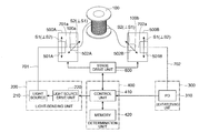
- FIG. 1 is a diagram showing an example of a specific device configuration for implementing the method of measuring the inter-core crosstalk of a multi-core optical fiber according to the present invention.
- FIG. 2 is a diagram showing another example of a specific device configuration for implementing the method of measuring the inter-core crosstalk of a multi-core optical fiber according to the present invention. Note that, although only a light-sending unit 200 A is disclosed in FIG. 2 , the remaining configuration of the measuring device to which the light-sending unit 200 A is applied is the same as the device configuration of FIG. 1 .
- the measuring device shown in FIG. 1 includes an adjustment mechanism for mechanically adjusting the light entering state and the light emitting state to and from a multi-core optical fiber 100 to be measured, a light-sending unit 200 for transmitting a measurement beam, a light-receiving unit 300 for receiving the crosstalk light, and a determination unit 400 .
- the adjustment mechanism includes a light-sending-side stage 500 A to which is fixed an entrance end 100 a of the multi-core optical fiber 100 to be measured, a light-receiving-side stage 500 B to which is fixed an emission end 100 b of the multi-core optical fiber 100 , and a stage drive unit 600 for individually performing the attitude control of these stages 500 A, 500 B.
- the light-sending unit 200 includes a light source 210 , and a light source drive unit 220 for sweeping the wavelength of the measurement beam emitted from the light source 210 in a predetermined range.
- the measurement beam outputted from the light source 210 is guided to the light-sending optical fiber 701 , and the emission end 701 a of the light-sending optical fiber 701 is fixed to the light-sending-side stage 500 A.
- the light-receiving unit 300 includes a light-receiving element 310 (PD) for receiving the crosstalk light emitted from the emission end 100 b of the multi-core optical fiber 100 via the light-receiving optical fiber 702 in which the entrance end 702 a is fixed to the light-receiving-side stage 500 B.
- PD light-receiving element 310
- the determination unit 400 includes a control unit 410 for performing the drive control of the stage drive unit 600 and the light source drive unit 220 , and acquiring the measurement value from the PD 310 and implementing the measuring method of this embodiment, and a memory 420 for storing various measurement data and the like.
- the light-sending-side stage 500 A comprises a seating 501 A capable of moving along the horizontal direction shown with arrow S 1 in a state of retaining the emission end 701 a of the light-sending optical fiber 701 , and a seating 502 A capable of moving in the vertical direction shown with arrow S 2 ( ⁇ S 1 ) which is orthogonal to the arrow S 1 in a state of retaining the entrance end 100 a of the multi-core optical fiber 100 .
- the stage drive unit 600 optically connects, for example, the emission end 701 a of the light-sending optical fiber 701 and the core m disposed on the entrance end 100 a of the multi-core optical fiber 100 by moving the seating 501 A a predetermined amount in the horizontal direction, and moving the seating 502 A a predetermined amount in the vertical direction.
- the light-receiving-side stage 500 B comprises a seating 501 B capable of moving along the horizontal direction shown with arrow S 1 ( ⁇ S 2 ) in a state of retaining the entrance end 702 a of the light-sending optical fiber 702 , and a seating 502 B capable of moving in the vertical direction shown with arrow S 2 ( ⁇ S 1 ) which is orthogonal to the arrow S 1 in a state of retaining the emission end 100 b of the multi-core optical fiber 100 .
- the stage drive unit 600 optically connects, for example, the entrance end 702 a of the light-sending optical fiber 702 and the core n disposed on the emission end 100 b of the multi-core optical fiber 100 by moving the seating 501 B a predetermined amount in the horizontal direction, and moving the seating 502 B a predetermined amount in the vertical direction.
- a coupling device spatial optical system, optical fiber coupler or the like capable of individually inputting and outputting light to and from the respective cores.
- the coupling device and the fibers 701 , 702 may be connected manually without depending on the light-sending-side stage 500 A and the light-receiving-side stage 500 B. Based on this kind of adjustment mechanism, it is possible to select the core to which the measuring light should enter via the emission end 701 a of the light-sending optical fiber 701 among the plurality of cores disposed on the entrance end 100 a of the multi-core optical fiber 100 to be measured, and select the core to receive the crosstalk light via the entrance end 702 a of the light-receiving optical fiber 702 among the plurality of cores disposed on the emission end 100 b of the multi-core optical fiber 100 .
- the control unit 410 can acquire the set of crosstalk values between cores as a result of the entrance-side core m and the emission-side core n being arbitrarily selected while changing the wavelength or polarization state of the measurement beam.
- the foregoing light-sending unit 200 functions as light source means for emitting a measurement beam while changing the wavelength, but in substitute for this light-sending unit 200 , the light-sending unit 200 A which emits a measurement beam while changing the polarization state of the measurement beam may also be applied to the measuring device shown in FIG. 1 .
- the light-sending unit 200 A of FIG. 2 comprises, in addition to the light source 210 , a polarization element 230 for changing the polarization state of the light emitted from the light source 210 into the intended state, and a drive unit 240 for performing attitude control of the polarization element 230 according to instructions from the control unit 430 .
- Light that passed through the polarization element 230 among the light emitted from the light source 210 is guided as the measurement beam to the light-sending optical fiber 701 .
- phase difference between the cores of the multi-core optical fiber can be represented as shown in the following formula (14).
- ⁇ nm ⁇ ( ⁇ ) ⁇ 2 ⁇ ⁇ ⁇ ⁇ n eff , n ⁇ D nm ⁇ ⁇ ⁇ R ( 15 )
- FIG. 3 shows an example of the relation of the wavelength and ⁇ nm ( ⁇ ) when n eff, n is 1.444, ⁇ is 2 ⁇ 0.1 [rad/m], D nm is 45 ⁇ m, and R is 140 mm.
- the inter-core phase difference at the zero point changes about three times. Accordingly, it can be understood that a sufficient change of the phase difference can be attained by changing the wavelength to be used in the measurement.
- the relation between the wavelength and the average value XT ⁇ of the crosstalk distribution in relation to the wavelength dependency of the coupling coefficient of the multi-core optical fiber is shown in FIG. 4 .
- the logarithmic expression of XT ⁇ is basically linear relative to the wavelength.
- This fiber is a fiber in which the wavelength dependency of the coupling coefficient is large, but even still the inclination of 10 ⁇ log 10 XT ⁇ relative to the wavelength is inhibited to approximately 0.14 dB/nm or less as shown in FIG. 4 .
- the wavelength sweep width ⁇ range is 2 ⁇ dev
- XT ⁇ changes in a range of the following formula (17).
- XT ⁇ changes in a range of ⁇ S ⁇ dev dB.
- the average value XT ⁇ , meas of the crosstalk distribution measured by the wavelength sweep can be presented as shown in the following formula (18).
- the difference between the average value XT ⁇ , meas of the crosstalk distribution measured by the wavelength sweep and the average value XT ⁇ , ⁇ 0 of the crosstalk distribution in the center wavelength of the wavelength sweep is dependent on S ⁇ dev .
- the foregoing difference does not depend on the width of the wavelength range in which the wavelength sweep was performed, and depends on the variation of the average value of the crosstalk distribution in the wavelength sweep range or the variation of the coupling coefficient in the wavelength sweep range.
- the crosstalk value in the foregoing wavelength range varies at 20 dB or more.
- the error can be kept to 0.2 dB or less, it shows high measurement accuracy, and, if the change of XT ⁇ in the wavelength sweep range is approximately 4.6 dB or less, the average value XT ⁇ , ⁇ 0 of the statistical distribution of the crosstalk in the specific wavelength ⁇ 0 can be measured with sufficient accuracy.
- the average value XT ⁇ , ⁇ 0 of the statistical distribution of the crosstalk in the specific wavelength ⁇ 0 can be measured with sufficient accuracy if 2S ⁇ dev is approximately 4.6 dB or less.
- f lin ⁇ ( ⁇ ) XT lin ⁇ 10 S ⁇ ( ⁇ - ⁇ 0 ) 10 ( 19 ⁇ a )
- f dB ⁇ ( ⁇ ) XT dB + S ⁇ ( ⁇ - ⁇ 0 ) ( 19 ⁇ b )
- FIG. 6 shows the difference in the probability distribution shape based on the difference in 2S ⁇ dev . It can be seen that the probability distribution shape changes according to the change of 2S ⁇ dev .
- FIG. 7 shows the results of actually measuring the inter-core crosstalk of the multi-core optical fiber while changing the wavelength of the incident light in a predetermined range including the specific wavelength.
- the measured wavelength range is 1620 to 1630 nm, and 2001 points were measured in the wavelength range of 10 nm.
- FIG. 8 shows the results of plotting the crosstalk values as the probability distribution. As shown in FIG. 8 , it can be seen that the probability distribution reliably follows the formula (12) as described above.
- FIG. 9 shows the absolute value of the change in the XT average value when ⁇ range is fixed at 10 nm and the sample value count N is changed.
- the solid line in FIG. 9 shows the XT average value based on the respective measured values of the center core #1 and the outer peripheral cores #2 to 7, and the broken line in FIG. 9 is the line showing the upper limit of variation between the respective measured values and the XT average value.
- FIG. 9 shows the absolute value of the change in the XT average value when ⁇ range is fixed at 10 nm and the sample value count N is changed.
- the respective groupings shown in FIG. 9 are data related to the XT between center core #1 and outer peripheral cores #2 to 7, and uses, as the reference, the XT average value when measuring the respective grouping
- N ⁇ 130 is required for the absolute value of the change in the XT average value to be 1 dB or less.
- approximately N ⁇ 200 is required for the absolute value of the change in the XT average value to be 0.5 dB or less
- approximately N ⁇ 300 is required to be 0.2 dB or less
- approximately N ⁇ 380 is required to be 0.1 dB or less.
- FIG. 10 shows the change of the XT average value upon changing ⁇ range .
- data in which the wavelength step was measured as 5 pm is used.
- ⁇ range 10 nm
- approximately ⁇ range ⁇ 5.2 nm is required for the absolute value of the change in the XT average value to be 0.5 dB or less
- approximately ⁇ range ⁇ 8.8 nm is required to be 0.2 dB or less.
- the formula (4) can be represented as the following formula (21) when considering two polarization modes.
- a n, x (n zero + 1 ) A n , y ⁇ ( n zero + 1 ) ] T n ⁇ ( n zero ) ⁇ [ A n , x ⁇ ( n zero ) A n , y ⁇ ( n zero ) ] + K ⁇ ⁇ exp ⁇ ( j ⁇ random ) ⁇ T m ⁇ ( n zero ) ⁇ [ A m , x ⁇ ( n zero ) A m , y ⁇ ( n zero ) ] ( 21 )
- a n, x (n zero ) is the x-axis polarization component of a complex electric field amplitude of the core n after the zero point of the n zero -th equivalent propagation constant difference
- a n, y (n zero ) is the y-axis polarization component. Specifically, these are a Jones vector in the following formula (22).
- T n (n zero ) is the Jones matrix of the core n from immediately after the zero point of the n zero -th equivalent propagation constant difference to immediately before the zero point of the n zero +1st equivalent propagation constant difference.
- the formula (23) is distributed based on the probability distribution of equal variance. ⁇ A n,x ( n zero ) ⁇ ,I ⁇ A n,y ( n zero ) ⁇ , ⁇ A n,y ( n zero ) ⁇ ,I ⁇ A n,y ( n zero ) ⁇ (23)
- the Jones matrix even if the Jones vector is multiplied by the Jones matrix, only the polarization state; specifically the polarizing direction or the phase of the respective polarization components of the x-axis and the y-axis will change, and the variance of the probability distribution of the formula (23) will not change. It is natural for the Jones matrix to be different in the respective cores, and the Jones matrix between the respective zero points is also generally different in an actual multi-core optical fiber.
- the polarization state of the Jones vector to be multiplied to the Jones matrix changes, the polarization state of the Jones vector to be obtained as the product of the Jones matrix and the Jones vector will also change as a matter of course, and an amount of relative change of Jones vector polarization state between input and output is also changed. In other words, if the polarization state of the input is changes, the polarizing direction between the input and the output will change, and the phase of the respective polarization components of the x-axis and the y-axis will also change.
- phase difference between the core n and the core m of the respective polarization components of the x-axis and the y-axis at the respective zero points can be changed to a polarization state of the input light.
- the method of measuring the inter-core crosstalk of the multi-core optical fiber of this embodiment it is possible to obtain the statistical distribution of the inter-core crosstalk by measuring the inter-core crosstalk of the multi-core optical fiber while changing the wavelength of the light incident on the multi-core optical fiber within a predetermined range including the specific wavelength. Moreover, it is also possible to obtain the statistical distribution of the inter-core crosstalk by measuring the inter-core crosstalk of the multi-core optical fiber while changing the polarization state of the incident light entering the multi-core optical fiber. In either of the foregoing methods, there is no need to measure the crosstalk by rewinding the multi-core optical fiber and changing the phase difference between cores around the zero point of the equivalent propagation constant difference between cores. Thus, the characteristics of the inter-core crosstalk can be analyzed with a simpler method.
Abstract
Description
or a relation between the wavelength λ and a crosstalk decibel value obtained from the measurement is approximated with the following formula:
f DB(λ)=XT dB +S(λ−λ0)
A n(n zero+1)=A n(n zero)+Kexp(jφ random)A m(n zero) (4)
and the average value XTμ of the distribution is 4σ2.
Here, An, x(nzero) is the x-axis polarization component of a complex electric field amplitude of the core n after the zero point of the nzero-th equivalent propagation constant difference, and An, y(nzero) is the y-axis polarization component. Specifically, these are a Jones vector in the following formula (22).
Tn(nzero) is the Jones matrix of the core n from immediately after the zero point of the nzero-th equivalent propagation constant difference to immediately before the zero point of the nzero+1st equivalent propagation constant difference.
Claims (5)
f dB(λ)=XT dB +S(λ−λ0),
Applications Claiming Priority (6)
| Application Number | Priority Date | Filing Date | Title |
|---|---|---|---|
| JP2011-040523 | 2011-02-25 | ||
| JP2011040523 | 2011-02-25 | ||
| JPP2011-040523 | 2011-02-25 | ||
| JP2011-255359 | 2011-11-22 | ||
| JP2011255359 | 2011-11-22 | ||
| JPP2011-255359 | 2011-11-22 |
Publications (2)
| Publication Number | Publication Date |
|---|---|
| US20120250008A1 US20120250008A1 (en) | 2012-10-04 |
| US8842268B2 true US8842268B2 (en) | 2014-09-23 |
Family
ID=46899478
Family Applications (1)
| Application Number | Title | Priority Date | Filing Date |
|---|---|---|---|
| US13/401,992 Active 2032-08-31 US8842268B2 (en) | 2011-02-25 | 2012-02-22 | Measuring method for crosstalk between cores in multi-core optical fiber |
Country Status (3)
| Country | Link |
|---|---|
| US (1) | US8842268B2 (en) |
| JP (1) | JP5887997B2 (en) |
| CN (1) | CN102706535B (en) |
Cited By (1)
| Publication number | Priority date | Publication date | Assignee | Title |
|---|---|---|---|---|
| US20140125971A1 (en) * | 2012-11-08 | 2014-05-08 | Ofs Fitel, Llc | Device and method to measure the dmd and other parameters of a multicore optical fiber |
Families Citing this family (15)
| Publication number | Priority date | Publication date | Assignee | Title |
|---|---|---|---|---|
| JP2011237782A (en) * | 2010-04-13 | 2011-11-24 | Sumitomo Electric Ind Ltd | Optical branch element and optical communication system including the same |
| JP5517228B1 (en) * | 2013-04-16 | 2014-06-11 | 日本電信電話株式会社 | Method and system for evaluating crosstalk characteristics of multi-core optical fiber |
| JP5801926B1 (en) * | 2014-05-29 | 2015-10-28 | 日本電信電話株式会社 | Crosstalk measuring apparatus and measuring method for optical fiber amplifier |
| JP6475574B2 (en) * | 2015-06-02 | 2019-02-27 | 日本電信電話株式会社 | Crosstalk estimation system and crosstalk estimation method |
| JP5986272B1 (en) * | 2015-07-14 | 2016-09-06 | 日本電信電話株式会社 | Inter-core crosstalk evaluation method and system |
| JP6491762B2 (en) * | 2015-11-26 | 2019-03-27 | 日本電信電話株式会社 | Transmission quality estimation system, transmission quality estimation device, and transmission quality estimation method |
| JP6654104B2 (en) * | 2016-02-26 | 2020-02-26 | 株式会社フジクラ | Method and apparatus for measuring crosstalk of multi-core fiber |
| WO2017145629A1 (en) * | 2016-02-26 | 2017-08-31 | 株式会社フジクラ | Multi-core fiber cross talk measuring method and measuring apparatus |
| JP6665609B2 (en) * | 2016-03-17 | 2020-03-13 | 住友電気工業株式会社 | Light intensity measuring method and spatial mode measuring device |
| US10230468B2 (en) * | 2016-06-02 | 2019-03-12 | Huawei Technologies Co., Ltd. | Transmission adjustment for space division multiplexing of optical signals |
| JP6963184B2 (en) * | 2018-08-21 | 2021-11-05 | 日本電信電話株式会社 | Crosstalk estimation system |
| CN110445534B (en) * | 2019-08-13 | 2022-07-08 | 中天宽带技术有限公司 | Method, system and equipment for determining crosstalk value of multi-core optical fiber |
| CN111431621B (en) * | 2020-03-19 | 2021-03-26 | 华中科技大学 | Phase noise estimation method and signal compensation method of multi-core optical fiber |
| CN112697402B (en) * | 2020-12-15 | 2021-10-26 | 长飞光纤光缆股份有限公司 | Multi-core optical fiber testing method and device |
| CN115455355B (en) * | 2022-09-16 | 2023-07-25 | 苏州大学 | Method and device for detecting crosstalk between modes of multi-core few-mode optical fibers |
Citations (4)
| Publication number | Priority date | Publication date | Assignee | Title |
|---|---|---|---|---|
| US20060124842A1 (en) * | 2004-12-08 | 2006-06-15 | Fujitsu Limited | Measuring method and measuring apparatus for coherent crosstalk light |
| US7772541B2 (en) * | 2004-07-16 | 2010-08-10 | Luna Innnovations Incorporated | Fiber optic position and/or shape sensing based on rayleigh scatter |
| US7781724B2 (en) * | 2004-07-16 | 2010-08-24 | Luna Innovations Incorporated | Fiber optic position and shape sensing device and method relating thereto |
| US20130188949A1 (en) * | 2009-12-02 | 2013-07-25 | Ofs Fitel, Llc | Techniques For Reducing Crosstalk In Multicore Fibers |
Family Cites Families (7)
| Publication number | Priority date | Publication date | Assignee | Title |
|---|---|---|---|---|
| US4300816A (en) * | 1979-08-30 | 1981-11-17 | United Technologies Corporation | Wide band multicore optical fiber |
| FR2782799B1 (en) * | 1998-08-27 | 2000-11-17 | France Telecom | APPARATUS FOR MEASURING LINEAR PARADIAPHOTY OF MULTI-CORE FIBERS |
| US6611648B2 (en) * | 2001-05-09 | 2003-08-26 | Corning Incorporated | Optical fibers having cores with different propagation constants, and methods of manufacturing same |
| JP4892316B2 (en) * | 2006-11-06 | 2012-03-07 | 株式会社フジクラ | Multi-core fiber |
| JP4901599B2 (en) * | 2007-06-14 | 2012-03-21 | 株式会社フジクラ | Quartz-based image fiber for near infrared and its manufacturing method |
| JP4861960B2 (en) * | 2007-11-05 | 2012-01-25 | 日本電信電話株式会社 | Nonlinear penalty optical transmission availability determination apparatus and method, program, and computer-readable recording medium |
| DK2209029T3 (en) * | 2009-01-19 | 2015-04-13 | Sumitomo Electric Industries | optical fiber |
-
2012
- 2012-02-22 US US13/401,992 patent/US8842268B2/en active Active
- 2012-02-27 JP JP2012040544A patent/JP5887997B2/en active Active
- 2012-02-27 CN CN201210046940.5A patent/CN102706535B/en active Active
Patent Citations (4)
| Publication number | Priority date | Publication date | Assignee | Title |
|---|---|---|---|---|
| US7772541B2 (en) * | 2004-07-16 | 2010-08-10 | Luna Innnovations Incorporated | Fiber optic position and/or shape sensing based on rayleigh scatter |
| US7781724B2 (en) * | 2004-07-16 | 2010-08-24 | Luna Innovations Incorporated | Fiber optic position and shape sensing device and method relating thereto |
| US20060124842A1 (en) * | 2004-12-08 | 2006-06-15 | Fujitsu Limited | Measuring method and measuring apparatus for coherent crosstalk light |
| US20130188949A1 (en) * | 2009-12-02 | 2013-07-25 | Ofs Fitel, Llc | Techniques For Reducing Crosstalk In Multicore Fibers |
Non-Patent Citations (5)
| Title |
|---|
| John M. Fini, Benyuan Zhu, Thierry F. Taunay, and Man F. Yan, "Statistics of crosstalk in bent multicore fibers," Optics Express 15122, vol. 18, N014, Jul. 5, 2010. * |
| Tetsuya Hayashi et al., "Crosstalk Variation on Multi-Core Fibre due to Fibre Bend," Proc. ECOC We.8.F.6, Sep. 19-23, 2010. |
| Tetsuya Hayashi, Toshiki Taru, Osamu Shimakawa, Takashi Sasaki, and Eisuke Sasaoka, "Characterization of Crosstalk in Ultra-Low-Crosstalk Multi-Core Fiber," Journal of Lightwave Technology, vol. 30, No. 4, Feb. 15, 2012. * |
| Tetsuya Hayashi, Toshiki Taru, Osamu Shimakawa, Takashi Sasaki, and Eisuke Sasaoka, "Design and fabrication of ultra-low crosstalk and low-loss multi-core fiber," Optics Express 16576, vol. 19, No. 17, Aug. 15, 2011. * |
| Tetsuya Hayashi, Toshiki Taru, Osamu Shimakawa, Takashi Sasaki, and Eisuke Sasaoka, "Ultra-Low-Crosstalk Multi-Core Fiber Feasible to Ultra-Long-Haul Transmission," OSA/OFC/NFOEC, Mar. 6-10, 2011, ISBN: 978-1-55752-906-0, http://dx.doi.org/10.1364/NFOEC.2011.PDPC2. * |
Cited By (2)
| Publication number | Priority date | Publication date | Assignee | Title |
|---|---|---|---|---|
| US20140125971A1 (en) * | 2012-11-08 | 2014-05-08 | Ofs Fitel, Llc | Device and method to measure the dmd and other parameters of a multicore optical fiber |
| US9513189B2 (en) * | 2012-11-08 | 2016-12-06 | Ofs Fitel, Llc | Device and method to measure the DMD and other parameters of a multicore optical fiber |
Also Published As
| Publication number | Publication date |
|---|---|
| CN102706535B (en) | 2016-08-31 |
| US20120250008A1 (en) | 2012-10-04 |
| JP2013130558A (en) | 2013-07-04 |
| JP5887997B2 (en) | 2016-03-16 |
| CN102706535A (en) | 2012-10-03 |
Similar Documents
| Publication | Publication Date | Title |
|---|---|---|
| US8842268B2 (en) | Measuring method for crosstalk between cores in multi-core optical fiber | |
| JP6862712B2 (en) | Optical fiber evaluation method and optical fiber evaluation device | |
| JP4350380B2 (en) | Optical fiber backscatter polarization analysis | |
| US9766396B2 (en) | High backscattering waveguides | |
| US10775541B2 (en) | Optical-fiber output beam profile measurement method and optical-fiber output beam profile measurement apparatus | |
| CN110073174B (en) | Method and apparatus for determining shape parameters using a sensing optical fiber having a single core with multiple light propagation modes | |
| US8031989B2 (en) | Radiological and nuclear optical sensor | |
| US6946646B2 (en) | Method of evaluating fiber PMD using polarization optical time domain reflectometry | |
| KR20020021084A (en) | System and method for measuring polarization mode dispersion suitable for a production environment | |
| US4779003A (en) | Apparatus for measuring a droplet size distribution based on the scattered light intensity of light applied to the droplets | |
| CN104458217B (en) | Method for synchronously measuring attenuation coefficient and cut-off wavelength of optical fiber | |
| US4779978A (en) | Method of measuring the refractive index profile of optical fibers | |
| Feuermann et al. | Light leakage in optical fibers: experimental results, modeling and the consequences for solar concentrators | |
| US9377593B2 (en) | System and method of estimating beam mode content for waveguide alignment | |
| EP0145343A2 (en) | Optical fibre test method and apparatus for performing the method | |
| US20040227952A1 (en) | Characterization of optical fiber using fourier domain optical coherence tomography | |
| JP7200932B2 (en) | NONLINEARITY MEASUREMENT METHOD AND NONLINEARITY MEASUREMENT DEVICE | |
| US6657709B2 (en) | Apparatus and method for measuring polarization-dependent loss using repeated high speed polarization scrambling | |
| Chen et al. | Angle-resolved characterization and ray-optics modeling of fiber-optic sensors | |
| US20180263709A1 (en) | Optical shape sensing system, medical apparatus and method for optical shape sensing | |
| JP3257197B2 (en) | Method and apparatus for evaluating single mode optical fiber characteristics | |
| Varyshchuk et al. | Using a multimode polymer optical fiber as a high sensitivy strain sensor | |
| CN109506788A (en) | Optical wavelength measurement system based on Fourier's mode-locked laser | |
| US20220228859A1 (en) | Estimating core-cladding concentricity error in optical fibers using guided acoustic-wave brillouin scattering | |
| JP2020027070A (en) | Raman gain efficiency distribution test method and raman gain efficiency distribution test device |
Legal Events
| Date | Code | Title | Description |
|---|---|---|---|
| AS | Assignment |
Owner name: SUMITOMO ELECTRIC INDUSTRIES, LTD., JAPAN Free format text: ASSIGNMENT OF ASSIGNORS INTEREST;ASSIGNOR:HAYASHI, TETSUYA;REEL/FRAME:028359/0723 Effective date: 20120516 |
|
| STCF | Information on status: patent grant |
Free format text: PATENTED CASE |
|
| FEPP | Fee payment procedure |
Free format text: PAYOR NUMBER ASSIGNED (ORIGINAL EVENT CODE: ASPN); ENTITY STATUS OF PATENT OWNER: LARGE ENTITY |
|
| MAFP | Maintenance fee payment |
Free format text: PAYMENT OF MAINTENANCE FEE, 4TH YEAR, LARGE ENTITY (ORIGINAL EVENT CODE: M1551) Year of fee payment: 4 |
|
| MAFP | Maintenance fee payment |
Free format text: PAYMENT OF MAINTENANCE FEE, 8TH YEAR, LARGE ENTITY (ORIGINAL EVENT CODE: M1552); ENTITY STATUS OF PATENT OWNER: LARGE ENTITY Year of fee payment: 8 |