US8831772B2 - Lift apparatus for stable placement of components into a rack - Google Patents
Lift apparatus for stable placement of components into a rack Download PDFInfo
- Publication number
- US8831772B2 US8831772B2 US13/557,357 US201213557357A US8831772B2 US 8831772 B2 US8831772 B2 US 8831772B2 US 201213557357 A US201213557357 A US 201213557357A US 8831772 B2 US8831772 B2 US 8831772B2
- Authority
- US
- United States
- Prior art keywords
- rack
- component
- lift apparatus
- location
- uninstalled
- Prior art date
- Legal status (The legal status is an assumption and is not a legal conclusion. Google has not performed a legal analysis and makes no representation as to the accuracy of the status listed.)
- Expired - Fee Related, expires
Links
Images


Classifications
-
- G—PHYSICS
- G11—INFORMATION STORAGE
- G11B—INFORMATION STORAGE BASED ON RELATIVE MOVEMENT BETWEEN RECORD CARRIER AND TRANSDUCER
- G11B15/00—Driving, starting or stopping record carriers of filamentary or web form; Driving both such record carriers and heads; Guiding such record carriers or containers therefor; Control thereof; Control of operating function
- G11B15/675—Guiding containers, e.g. loading, ejecting cassettes
- G11B15/68—Automatic cassette changing arrangements; automatic tape changing arrangements
Definitions
- the present invention relates to the installation of information technology equipment in an appropriate position within a rack.
- ITE information technology equipment
- racks provide physical support for each ITE while maintaining accessibility for use and maintenance.
- racks also accommodate the provisioning of power, the communication of data, and the cooling of heat that emanates from the ITEs.
- rack stability is a determination of the rack's center of gravity. If the rack's center of mass is higher than a predetermined height, then the rack may become unbalanced and vulnerable to tipping.
- the actual limitations on the configuration or loading of a rack may be described by a set of best practices distributed by the rack manufacturer or the systems integrator.
- the rack configuration may be determined in consideration of all of the components that need to go into the rack. For example, the heavier components may be positioned in the lower portions of the rack. However, a rack may also receive one component at a time as a system is gradually expanded, modified or upgraded. Without knowing what other components will eventually fill the rack, the rack should remain stable after each additional component is installed.
- One embodiment of the present invention provides a method comprising using scales onboard a lift apparatus to weigh the uninstalled component that is positioned on the lift apparatus for installation into a rack.
- the method further comprises accessing data that identifies the weight and rack location of components currently installed in the rack, and determining one or more available rack locations where the component may be installed without violating one or more predetermined rack stability rules.
- the method then uses the lift apparatus to raise the component into a selected one of the one or more available rack locations.
- FIG. 1 is a diagram of a first lift apparatus capable of monitoring rack stability during installation of a component, such as a server, network switch or power distribution unit.
- a component such as a server, network switch or power distribution unit.
- FIG. 2 is a diagram of a lift apparatus capable of monitoring rack stability during installation of a component.
- FIG. 3 is a flowchart of a method of maintaining rack stability during installation of a component.
- One embodiment of the present invention provides a method comprising using scales onboard a lift apparatus to weigh the uninstalled component that is positioned on the lift apparatus for installation into a rack.
- the method further comprises accessing data that identifies the weight and rack location of components currently installed in the rack, and determining one or more available rack locations where the component may be installed without violating one or more predetermined rack stability rules.
- the method then uses the lift apparatus to raise the component into a selected one of the one or more available rack locations.
- the scales are preferably built into a horizontal lift platform upon which components are placed. In this manner, the act of weighing the component is performed by the lift apparatus without any additional act of the user. It is also advantageous that the scales weigh the actual component that is about to be lifted into position and installed.
- the data that identifies the weight and rack location of the components currently installed in the rack may be maintained and stored in association with the lift apparatus or a rack management module. That rack location may be a vertical height measurement relative to the base of the rack or an indicator that is representative of height, such as a bay number.
- the data may further include the size of the unit, such as 1U, 2U, etc., and/or a slide out distance that the unit might extend out of the rack for use or maintenance.
- the lift apparatus communicates with the rack management module in order to access the data.
- the communication may use a wireless protocol or a USB cable, and the communication may conform to a short range peer to peer network.
- having the management module maintain this data may be advantageous in some circumstances. For example, if one or more components have been replaced without the use of the lift apparatus (either by hand or with another unit of lift apparatus), the management module should be able to detect this change and update the data.
- the data is maintained by a computer that is onboard the lift apparatus and stored in an onboard computer readable medium.
- the computer needs to identify the particular rack in which the component is to be installed.
- a convenience manner of identifying the rack is to associate component inventory of each rack with a barcode that is physical secured to the rack.
- a barcode scanner in communication with the onboard computer may scan the barcode and thus identify the rack and use the appropriate data in the determination of rack location availability and rack stability.
- the barcode may be substituted with a radio frequency identification (RFID) tag, and the lift apparatus may be equipped with a RFID reader.
- RFID radio frequency identification
- the user may manually enter the weight of a previously installed unit or enter a serial number of a component that may be cross-referenced to the weight of the component.
- the lift apparatus and rack management module are in communication, includes each bay in the rack having a scale that measures the weight of the component that is installed there, such that the management module can then communicate the weight and rack location data to the lift apparatus.
- input is received from a user identifying a user-proposed rack location for the component to be installed.
- the method determines whether the installation of the component in the user-proposed location would violate the one or more predetermined rack stability rules.
- the lift apparatus may be prevented from lifting the component to a position that would violate the one or more predetermined rack stability rules. It is also an option to output an alert to the user that installing the component in the user-proposed location would violate the one or more predetermined rack stability rules.
- the method may identify all of the available locations in the rack where the component can be installed without violating one or more predetermined rack stability rules, and then output a list of all of the identified locations. The user may then select one of the identified locations from the list. Since the list identifies locations that satisfy stability requirements, the user may then select which of those locations best satisfy their usability requirements. For example, the user may prefer that a component with a slide out keyboard tray be installed in a location that is about waist high.
- the one or more predetermined rack stability rules may, for example, require that the center of mass for the combination of the rack and its installed component should not exceed a predetermined height.
- Alternative stability rules and alternative manners of calculating stability may be implemented as well.
- the methods of the present invention are not limited to any particular calculation for determining physical stability of the rack.
- the method may consider compliance with one or more component manufacturer rules about the proper installation of a component, such as a server.
- the method may include storing the component weight and rack location (for the newly installed component) in the database in response to installing the component.
- the component to be installed is preferably a unit of information technology equipment, such as a server, a network switch, or a power distribution unit.
- a rack will typically support a combination of these units and other types of units, including peripherals, cables and computer readable storage devices.
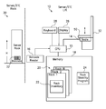
- FIG. 1 is a diagram of a lift apparatus 10 that is capable of monitoring the stability of a rack 30 during installation of a component 50 , such as a server.
- the lift apparatus 10 can be easily moved from one rack to another, and includes a lift mechanism 12 that is made to lift the component 50 vertically.
- the component 50 is placed on a platform 14 and lifted to an appropriate height H relative to the rack 30 for installation of the component into the rack.
- the platform 14 has a built-in scale for weighing the component.
- the CPU 15 causes a barcode reader 16 to read a barcode 32 that is physically secured to the rack.
- Each barcode 32 is used to uniquely identify the rack from among a plurality of N racks in a hypothetical datacenter.
- a computer readable memory 18 stores data 20 , include a record for each of the plurality of N racks.
- Each of the N rack records includes a rack inventory 22 that provides the current weight distribution in a given rack.
- the rack inventory 22 for a given rack may include the weight and rack location of each component.
- the rack inventory 22 may further include the size of the component, such as 1U, 2U and the like, and an indication whether the component is mounted on a slide for use or maintenance.
- the lift apparatus 10 has used the barcode reader 16 to read the barcode 32 identifying the rack, located the relevant rack inventory 22 in the data 20 , and used the scale in the platform 14 to weigh the component, then the lift apparatus 10 has the information needed for the rack stability program 24 .
- the rack stability program 24 determines, and outputs to a user (perhaps via the display 26 or other output device), which of the available rack locations, if any, can receive the component without violating one or more predetermined rack stability rules.
- the lift mechanism 12 is automatically prevented from lifting the component into a rack location that would result in a violation of the one or more predetermined rack stability rules.
- the user (perhaps using the keyboard 28 or other input device) inputs a desired rack location for installing the component 50 and the rack stability program 24 determines whether or not installing the component in the desired rack location would violate one or more of the rack stability rules.
- a hypothetical rack stability rule might require that the center of mass of the rack, in consideration of all current rack components as well as the component 50 that is proposed for installation, should not be higher than one half the full height of the rack 30 . If the rack is eight feet tall, then no component should be installed in the rack in a location that would result in the center of mass being higher than four feet above the base of the rack.
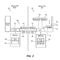
- FIG. 2 is a diagram of the lift apparatus 10 and rack 30 of FIG. 1 , except that the rack inventory 22 for the rack 30 is maintained by a management module 40 associated with the rack.
- the management module 40 includes a CPU 42 that receives data identifying each of the components currently installed in the rack 30 .
- the CPU 42 stores this data as a rack inventory 22 in memory 44 .
- the CPU 15 of the lift apparatus uses either a wireless device 27 or a USB port/cable 29 to communicate with a wireless device 47 or a USB port/cable 49 , respectively, of the rack management module 40 .
- the lift apparatus 10 may thus request that the rack management module 40 provide the rack inventory data 22 , or some information representative of the rack inventory data (such as the current center of mass, the current total mass, and a list of available locations). Then, the CPU 15 has access to all the same data as in the previous embodiment of FIG. 1 and is able to use the rack stability program 24 to identify rack locations, if any, where the component 50 may be installed without violating one or more predetermined rack stability rules. Alternatively, if a user requests installation of the component in a given location of the rack, then the rack stability program 24 may determine whether or not the component 50 may be installed in the given location without violating one or more predetermined rack stability rules.
- FIG. 3 is a flowchart of a method of maintaining rack stability during installation of a component.
- the method identifies the weight of the ITE in step 70 .
- the method obtains an inventory of components currently installed in the rack, where the rack inventory includes the weight and rack location of each component.
- step 74 if the user does not request a location for installation within the rack, then the method proceeds to run the rack stability program in step 84 and identify stable locations (i.e., locations that will not violate one or more rack stability rules) for the component to be installed in the rack in step 86 .
- stable locations i.e., locations that will not violate one or more rack stability rules
- step 88 outputs the stable locations to the user, perhaps using a display. Still further, if there are available locations in the rack but none of those locations would be stable, then the method may output proposed new configurations or rearrangements of the currently installed components in order to accommodate the new component.
- aspects of the present invention may be embodied as a system, method or computer program product. Accordingly, aspects of the present invention may take the form of an entirely hardware embodiment, an entirely software embodiment (including firmware, resident software, micro-code, etc.) or an embodiment combining software and hardware aspects that may all generally be referred to herein as a “circuit,” “module” or “system.” Furthermore, aspects of the present invention may take the form of a computer program product embodied in one or more computer readable medium(s) having computer readable program code embodied thereon.
- the computer readable medium may be a computer readable signal medium or a computer readable storage medium.
- a computer readable storage medium may be, for example, but not limited to, an electronic, magnetic, optical, electromagnetic, infrared, or semiconductor system, apparatus, or device, or any suitable combination of the foregoing.
- a computer readable storage medium may be any tangible medium that can contain, or store a program for use by or in connection with an instruction execution system, apparatus, or device.
- a computer readable signal medium may include a propagated data signal with computer readable program code embodied therein, for example, in baseband or as part of a carrier wave. Such a propagated signal may take any of a variety of forms, including, but not limited to, electro-magnetic, optical, or any suitable combination thereof.
- a computer readable signal medium may be any computer readable medium that is not a computer readable storage medium and that can communicate, propagate, or transport a program for use by or in connection with an instruction execution system, apparatus, or device.
- Program code embodied on a computer readable medium may be transmitted using any appropriate medium, including but not limited to wireless, wireline, optical fiber cable, RF, etc., or any suitable combination of the foregoing.
- Computer program code for carrying out operations for aspects of the present invention may be written in any combination of one or more programming languages, including an object oriented programming language such as Java, Smalltalk, C++ or the like and conventional procedural programming languages, such as the “C” programming language or similar programming languages.
- the program code may execute entirely on the user's computer, partly on the user's computer, as a stand-alone software package, partly on the user's computer and partly on a remote computer or entirely on the remote computer or server.
- the remote computer may be connected to the user's computer through any type of network, including a local area network (LAN) or a wide area network (WAN), or the connection may be made to an external computer (for example, through the Internet using an Internet Service Provider).
- LAN local area network
- WAN wide area network
- Internet Service Provider an Internet Service Provider
- These computer program instructions may also be stored in a computer readable medium that can direct a computer, other programmable data processing apparatus, or other devices to function in a particular manner, such that the instructions stored in the computer readable medium produce an article of manufacture including instructions which implement the function/act specified in the flowchart and/or block diagram block or blocks.
- the computer program instructions may also be loaded onto a computer, other programmable data processing apparatus, or other devices to cause a series of operational steps to be performed on the computer, other programmable apparatus or other devices to produce a computer implemented process such that the instructions which execute on the computer or other programmable apparatus provide processes for implementing the functions/acts specified in the flowchart and/or block diagram block or blocks.
- each block in the flowchart or block diagrams may represent a module, segment, or portion of code, which comprises one or more executable instructions for implementing the specified logical function(s).
- the functions noted in the block may occur out of the order noted in the figures. For example, two blocks shown in succession may, in fact, be executed substantially concurrently, or the blocks may sometimes be executed in the reverse order, depending upon the functionality involved.
Abstract
Description
Claims (17)
Priority Applications (1)
| Application Number | Priority Date | Filing Date | Title |
|---|---|---|---|
| US13/557,357 US8831772B2 (en) | 2012-07-25 | 2012-07-25 | Lift apparatus for stable placement of components into a rack |
Applications Claiming Priority (1)
| Application Number | Priority Date | Filing Date | Title |
|---|---|---|---|
| US13/557,357 US8831772B2 (en) | 2012-07-25 | 2012-07-25 | Lift apparatus for stable placement of components into a rack |
Publications (2)
| Publication Number | Publication Date |
|---|---|
| US20140031971A1 US20140031971A1 (en) | 2014-01-30 |
| US8831772B2 true US8831772B2 (en) | 2014-09-09 |
Family
ID=49995614
Family Applications (1)
| Application Number | Title | Priority Date | Filing Date |
|---|---|---|---|
| US13/557,357 Expired - Fee Related US8831772B2 (en) | 2012-07-25 | 2012-07-25 | Lift apparatus for stable placement of components into a rack |
Country Status (1)
| Country | Link |
|---|---|
| US (1) | US8831772B2 (en) |
Cited By (1)
| Publication number | Priority date | Publication date | Assignee | Title |
|---|---|---|---|---|
| US20190174650A1 (en) * | 2016-08-31 | 2019-06-06 | Commscope Technologies Llc | Systems and methods for monitoring the presence of rack mounted equipment |
Families Citing this family (5)
| Publication number | Priority date | Publication date | Assignee | Title |
|---|---|---|---|---|
| WO2016088118A1 (en) * | 2014-12-04 | 2016-06-09 | Assembrix Ltd. | Orientation optimization in 3d printing |
| US10587935B2 (en) * | 2015-06-05 | 2020-03-10 | Quanta Computer Inc. | System and method for automatically determining server rack weight |
| US10132711B2 (en) | 2016-10-31 | 2018-11-20 | International Business Machines Corporation | Static and dynamic stability measurement and optimization system |
| US10467542B2 (en) | 2016-11-22 | 2019-11-05 | International Business Machines Corporation | Embedded dynamic stability measurement, optimization and alarm system |
| EP3988476A1 (en) * | 2020-10-26 | 2022-04-27 | BITO-Lagertechnik Bittmann GmbH | Method for storing load carriers in a rack |
Citations (13)
| Publication number | Priority date | Publication date | Assignee | Title |
|---|---|---|---|---|
| US4007843A (en) | 1972-07-17 | 1977-02-15 | Rapistan, Incorporated | Multi-aisle warehouse system with mobile lift having control means for an article transfer vehicle |
| US4820101A (en) | 1982-09-30 | 1989-04-11 | Fenn Ronald L | Automated in-process pipe storage and retrieval system |
| US5222855A (en) | 1986-01-02 | 1993-06-29 | Computer Aided Systems, Inc. | Automated work center |
| US5362197A (en) | 1990-05-07 | 1994-11-08 | Stanley-Vidmar, Inc. | Automatic storage and retrieval system |
| US5850539A (en) * | 1995-05-23 | 1998-12-15 | Compaq Computer Corporation | Automated system for facilitating creation of a rack-mountable component personal computer |
| US5993045A (en) | 1997-05-09 | 1999-11-30 | Hewlett-Packard Company | Data cartridge caddy presence sensing method and apparatus |
| US6332098B2 (en) | 1998-08-07 | 2001-12-18 | Fedex Corporation | Methods for shipping freight |
| US6378119B1 (en) * | 1999-05-24 | 2002-04-23 | Dell Usa, L.P. | Method and system for adaptive component placement |
| US7286969B2 (en) * | 2003-07-18 | 2007-10-23 | Hewlett Packard Development Company, L.P. | Method for determining placement of components in rack |
| US20080281717A1 (en) | 2005-03-09 | 2008-11-13 | Sami Kortelainen | Method for Placing a Palletless Goods Package in a Stock Shelf and Delivering Therefrom and for Controlling Logistics of Packages |
| US20100316469A1 (en) | 2009-04-10 | 2010-12-16 | Casepick Systems, Llc | Autonomous transports for storage and retrieval systems |
| US7857214B2 (en) * | 2007-04-26 | 2010-12-28 | Liebert Corporation | Intelligent track system for mounting electronic equipment |
| US20110020098A1 (en) | 2007-10-26 | 2011-01-27 | Bernd Pfaffmann | Storage rack with loading management |
-
2012
- 2012-07-25 US US13/557,357 patent/US8831772B2/en not_active Expired - Fee Related
Patent Citations (15)
| Publication number | Priority date | Publication date | Assignee | Title |
|---|---|---|---|---|
| US4007843A (en) | 1972-07-17 | 1977-02-15 | Rapistan, Incorporated | Multi-aisle warehouse system with mobile lift having control means for an article transfer vehicle |
| US4820101A (en) | 1982-09-30 | 1989-04-11 | Fenn Ronald L | Automated in-process pipe storage and retrieval system |
| US5222855A (en) | 1986-01-02 | 1993-06-29 | Computer Aided Systems, Inc. | Automated work center |
| US5362197A (en) | 1990-05-07 | 1994-11-08 | Stanley-Vidmar, Inc. | Automatic storage and retrieval system |
| US5850539A (en) * | 1995-05-23 | 1998-12-15 | Compaq Computer Corporation | Automated system for facilitating creation of a rack-mountable component personal computer |
| US5993045A (en) | 1997-05-09 | 1999-11-30 | Hewlett-Packard Company | Data cartridge caddy presence sensing method and apparatus |
| US6332098B2 (en) | 1998-08-07 | 2001-12-18 | Fedex Corporation | Methods for shipping freight |
| US6378119B1 (en) * | 1999-05-24 | 2002-04-23 | Dell Usa, L.P. | Method and system for adaptive component placement |
| US7286969B2 (en) * | 2003-07-18 | 2007-10-23 | Hewlett Packard Development Company, L.P. | Method for determining placement of components in rack |
| US20080281717A1 (en) | 2005-03-09 | 2008-11-13 | Sami Kortelainen | Method for Placing a Palletless Goods Package in a Stock Shelf and Delivering Therefrom and for Controlling Logistics of Packages |
| US7857214B2 (en) * | 2007-04-26 | 2010-12-28 | Liebert Corporation | Intelligent track system for mounting electronic equipment |
| US20110020098A1 (en) | 2007-10-26 | 2011-01-27 | Bernd Pfaffmann | Storage rack with loading management |
| US20100316469A1 (en) | 2009-04-10 | 2010-12-16 | Casepick Systems, Llc | Autonomous transports for storage and retrieval systems |
| US20100316470A1 (en) | 2009-04-10 | 2010-12-16 | Casepick Systems, Llc | Control system for storage and retrieval systems |
| US20100316468A1 (en) | 2009-04-10 | 2010-12-16 | Casepick Systems, Llc | Storage and retrieval system |
Non-Patent Citations (1)
| Title |
|---|
| Binar, "Quick-Lift Systems", http://www.kahlman.se/uk/default.asp, Mar. 5, 2012, 1 Page. |
Cited By (2)
| Publication number | Priority date | Publication date | Assignee | Title |
|---|---|---|---|---|
| US20190174650A1 (en) * | 2016-08-31 | 2019-06-06 | Commscope Technologies Llc | Systems and methods for monitoring the presence of rack mounted equipment |
| US10820444B2 (en) * | 2016-08-31 | 2020-10-27 | Commscope Technologies Llc | Systems and methods for monitoring the presence of rack mounted equipment |
Also Published As
| Publication number | Publication date |
|---|---|
| US20140031971A1 (en) | 2014-01-30 |
Similar Documents
| Publication | Publication Date | Title |
|---|---|---|
| US8831772B2 (en) | Lift apparatus for stable placement of components into a rack | |
| US9602976B1 (en) | Locating electronic devices in an electronic equipment rack | |
| US11582130B2 (en) | Performance monitoring in a distributed storage system | |
| US20110153466A1 (en) | Sensor based inventory management system and method | |
| US9436734B2 (en) | Relative performance prediction of a replacement database management system (DBMS) | |
| US20140372237A1 (en) | Systems and methods facilitating in-aisle scanning | |
| WO2014093720A1 (en) | Multi-screen application enabling and distribution service | |
| CN110418569B (en) | Method and device for determining installation position of server, electronic equipment and medium | |
| US20160092887A1 (en) | Application license distribution and management | |
| US20190158367A1 (en) | Selection of cloud service providers to host applications | |
| CN103917981A (en) | Unauthorized application detection system and method | |
| CN108255654A (en) | Automatic testing method and device | |
| CN106575414B (en) | Contextual platform feature recommendation | |
| CN107403112B (en) | Data checking method and equipment thereof | |
| US10338987B2 (en) | Testing module compatibility | |
| US20120311718A1 (en) | System and method for performing a software comparison | |
| EP3240309A1 (en) | Information processing device, information processing program, and information processing method | |
| WO2009112326A1 (en) | Method, system and apparatus for determining the power supply requirements of a data processing system | |
| US9686168B1 (en) | Managing component capacity | |
| CN112507807A (en) | Article storage control method and device, storage medium and electronic device | |
| US8561075B2 (en) | Load balancing servers | |
| CN108064362A (en) | The heat for being exclusively used in device slows down | |
| US11397105B2 (en) | Modular wireless scale system comprising microscales | |
| JP6293966B2 (en) | Database management apparatus, database management method, and database management program | |
| JP2008059446A (en) | Production control device, production control method, and computer program therefor |
Legal Events
| Date | Code | Title | Description |
|---|---|---|---|
| AS | Assignment |
Owner name: INTERNATIONAL BUSINESS MACHINES CORPORATION, NEW Y Free format text: ASSIGNMENT OF ASSIGNORS INTEREST;ASSIGNORS:BRIDGES, JEREMY S.;DECESARIS, MICHAEL;REMIS, LUKE D.;AND OTHERS;REEL/FRAME:028632/0978 Effective date: 20120709 |
|
| STCF | Information on status: patent grant |
Free format text: PATENTED CASE |
|
| AS | Assignment |
Owner name: LENOVO INTERNATIONAL LIMITED, HONG KONG Free format text: ASSIGNMENT OF ASSIGNORS INTEREST;ASSIGNOR:INTERNATIONAL BUSINESS MACHINES CORPORATION;REEL/FRAME:034194/0291 Effective date: 20140926 |
|
| FEPP | Fee payment procedure |
Free format text: SURCHARGE FOR LATE PAYMENT, LARGE ENTITY (ORIGINAL EVENT CODE: M1554) |
|
| MAFP | Maintenance fee payment |
Free format text: PAYMENT OF MAINTENANCE FEE, 4TH YEAR, LARGE ENTITY (ORIGINAL EVENT CODE: M1551) Year of fee payment: 4 |
|
| FEPP | Fee payment procedure |
Free format text: MAINTENANCE FEE REMINDER MAILED (ORIGINAL EVENT CODE: REM.); ENTITY STATUS OF PATENT OWNER: LARGE ENTITY |
|
| LAPS | Lapse for failure to pay maintenance fees |
Free format text: PATENT EXPIRED FOR FAILURE TO PAY MAINTENANCE FEES (ORIGINAL EVENT CODE: EXP.); ENTITY STATUS OF PATENT OWNER: LARGE ENTITY |
|
| STCH | Information on status: patent discontinuation |
Free format text: PATENT EXPIRED DUE TO NONPAYMENT OF MAINTENANCE FEES UNDER 37 CFR 1.362 |
|
| FP | Lapsed due to failure to pay maintenance fee |
Effective date: 20220909 |