US8826032B1 - Systems and methods for network change discovery and host name resolution in storage network environments - Google Patents
Systems and methods for network change discovery and host name resolution in storage network environments Download PDFInfo
- Publication number
- US8826032B1 US8826032B1 US11/965,392 US96539207A US8826032B1 US 8826032 B1 US8826032 B1 US 8826032B1 US 96539207 A US96539207 A US 96539207A US 8826032 B1 US8826032 B1 US 8826032B1
- Authority
- US
- United States
- Prior art keywords
- hash function
- value
- components
- storage network
- timestamp
- Prior art date
- Legal status (The legal status is an assumption and is not a legal conclusion. Google has not performed a legal analysis and makes no representation as to the accuracy of the status listed.)
- Active, expires
Links
Images


Classifications
-
- H—ELECTRICITY
- H04—ELECTRIC COMMUNICATION TECHNIQUE
- H04L—TRANSMISSION OF DIGITAL INFORMATION, e.g. TELEGRAPHIC COMMUNICATION
- H04L41/00—Arrangements for maintenance, administration or management of data switching networks, e.g. of packet switching networks
- H04L41/06—Management of faults, events, alarms or notifications
- H04L41/0686—Additional information in the notification, e.g. enhancement of specific meta-data
-
- H—ELECTRICITY
- H04—ELECTRIC COMMUNICATION TECHNIQUE
- H04L—TRANSMISSION OF DIGITAL INFORMATION, e.g. TELEGRAPHIC COMMUNICATION
- H04L41/00—Arrangements for maintenance, administration or management of data switching networks, e.g. of packet switching networks
- H04L41/06—Management of faults, events, alarms or notifications
- H04L41/069—Management of faults, events, alarms or notifications using logs of notifications; Post-processing of notifications
-
- H—ELECTRICITY
- H04—ELECTRIC COMMUNICATION TECHNIQUE
- H04L—TRANSMISSION OF DIGITAL INFORMATION, e.g. TELEGRAPHIC COMMUNICATION
- H04L43/00—Arrangements for monitoring or testing data switching networks
- H04L43/08—Monitoring or testing based on specific metrics, e.g. QoS, energy consumption or environmental parameters
- H04L43/0805—Monitoring or testing based on specific metrics, e.g. QoS, energy consumption or environmental parameters by checking availability
- H04L43/0817—Monitoring or testing based on specific metrics, e.g. QoS, energy consumption or environmental parameters by checking availability by checking functioning
-
- H—ELECTRICITY
- H04—ELECTRIC COMMUNICATION TECHNIQUE
- H04L—TRANSMISSION OF DIGITAL INFORMATION, e.g. TELEGRAPHIC COMMUNICATION
- H04L67/00—Network arrangements or protocols for supporting network services or applications
- H04L67/01—Protocols
- H04L67/10—Protocols in which an application is distributed across nodes in the network
- H04L67/1097—Protocols in which an application is distributed across nodes in the network for distributed storage of data in networks, e.g. transport arrangements for network file system [NFS], storage area networks [SAN] or network attached storage [NAS]
-
- H—ELECTRICITY
- H04—ELECTRIC COMMUNICATION TECHNIQUE
- H04L—TRANSMISSION OF DIGITAL INFORMATION, e.g. TELEGRAPHIC COMMUNICATION
- H04L2101/00—Indexing scheme associated with group H04L61/00
- H04L2101/60—Types of network addresses
- H04L2101/618—Details of network addresses
-
- H—ELECTRICITY
- H04—ELECTRIC COMMUNICATION TECHNIQUE
- H04L—TRANSMISSION OF DIGITAL INFORMATION, e.g. TELEGRAPHIC COMMUNICATION
- H04L43/00—Arrangements for monitoring or testing data switching networks
- H04L43/10—Active monitoring, e.g. heartbeat, ping or trace-route
-
- H—ELECTRICITY
- H04—ELECTRIC COMMUNICATION TECHNIQUE
- H04L—TRANSMISSION OF DIGITAL INFORMATION, e.g. TELEGRAPHIC COMMUNICATION
- H04L61/00—Network arrangements, protocols or services for addressing or naming
- H04L61/45—Network directories; Name-to-address mapping
- H04L61/4505—Network directories; Name-to-address mapping using standardised directories; using standardised directory access protocols
- H04L61/4511—Network directories; Name-to-address mapping using standardised directories; using standardised directory access protocols using domain name system [DNS]
Definitions
- the systems and methods generally relate to efficient discovery of changes in storage network environments and to resolution of host names in a storage network environment.
- Storage area networks or storage network environments are dedicated networks for enabling multiple applications on hosts access to data stored in consolidated shared storage infrastructures. In storage network environments, it may be important to detect changes and determine the implications of these changes on the storage service levels provided to applications and hosts. Enterprises are deploying increasingly large-scale SANs in order to gain economies-of-scale business benefits, and are performing and planning massive business-critical migration processes to these new environments.
- Enterprise SANs are increasingly supporting most of the business critical applications in enterprises. These SAN are increasingly large and complex.
- a typical SAN environment in a Fortune 500 company may contain hundreds or thousands of servers and tens or hundreds of switches and storage devices of different types. Furthermore these SAN environments are undergoing a large amount of change and growth.
- each application on a SAN-connected host typically requires access, and often exclusive access, only to some specific SAN data objects (LUNs). Consequently, in storage area networks each source end point, i.e., the application on a host, will typically need to interact only, and often exclusively, with a specific, small number of target end points, e.g., the LUNs on the network storage devices.
- LUNs SAN data objects
- An access path or a logical access path will encompass a logical channel between a given application and a given data object, e.g. LUN, along which data may flow.
- a logical access path is typically, although not exclusively, a sequence of components starting with a specific application on a specific server via, for example, an HBA, and a sequence of one or more switches and physical links leading to a storage controller and a storage device containing a data object e.g. a LUN.
- the logical or configuration state of each component along the way in that sequence for example, the HBA, the storage controller, or the switches, is set such as to not disable data flow between that specific application and that specific data object along that specific sequence.
- Changes within a storage network environment are difficult to detect. For instance, a failure of a storage area network switch may eliminate an access path between two components on the network thereby disrupting the corresponding data flow. Because of the potentially very large number of components in the storage network environment, very frequent storage network environment changes, and large amount of local state information of each component, and because of the complexity of performing the correlation of the information and analysis of the end-to-end access paths and attributes, any change detection approach needs to be very efficient to perform the task of detecting changes effectively in realistic environments.
- the systems and methods described herein include processes for efficiently detecting relevant state changes in storage network environments by selecting a subset of states or a subset of state variables for each component type to be tracked, periodically receiving state information consisting of the values of the selected states with an associated timestamp and a component identifier (ID) for the storage network components, computing a function value of the received states using a pre-selected hash function, looking up the most-recent locally-stored hash function value associated with that component ID, and in case the hash function value is different from the most-recently locally-stored value, storing the new hash function value and the timestamp associated with that new value and component ID, and forwarding to a Global Analyzer the component ID, associated timestamp, and component state.
- ID component identifier
- the states of the component may include the configuration state and/or the internal execution state.
- a state of a switch may include a list of zones in the storage network environment and the member names for each of these zones.
- a subset of states e.g. internal execution states and/or configuration states are selected.
- the process may select one or more of the elements in the configuration state.
- the systems and methods described herein include, among other things, processes for detecting state changes in storage network environments.
- these processes select a subset of the states or a subset of state variables for the components in the storage network environment.
- the subset of state variables may be one or more of the states of any of the components in the storage network environment.
- the process may periodically receive the states, associated timestamps, and component identifiers, from components in the storage network environment.
- the process may compute hash function values of a received state or states using a pre-selected hash function. A most-recently locally-stored hash function value associated with the component identifier may be compared to a most-recently received state hash function value.
- the process may locally store the most-recently received hash function value, the associated timestamp, and the component identifier. The process may then send the component identifier, the associated timestamp, and the state hash function value to a global analyzer.
- Selecting the subset of states may comprise choosing variables which impact a level of storage service provided to an application such that a fluctuation rate of the value for each state variable is lower than a pre-selected fluctuation threshold.
- the process may periodically receive values of the component's selected state variables as a result of a response to a polling request, as the result of an unsolicited update, or through some other technique.
- the process may compute hash functions for the states it received, and send only these values to the global analyzer service if the corresponding hash function values differ from the corresponding previously locally-stored and computed values. If the values differ, the process may send to a global analyzer service the component identifier, the associated timestamp, and the state value if the compared values are not equal. Alternatively, the process may not send to the global analyzer service the component identifier, the associated timestamp, and the state value if the most-recently locally-stored associated timestamp and the most-recently received associated timestamp are equal.
- systems for detecting state changes in storage network environments comprise a global analyzer for processing component identifiers, associated timestamps, and state values for states of components in the storage network environment, and component interaction modules connected to the global analyzer for computing and locally storing the component identifiers, the associated timestamps, and the state hash function values.
- the systems and methods described herein provide processes for resolving the name of hosts in a storage network environment.
- Such processes may comprise deriving logical access paths in the storage network environment from storage network component information, and deriving a host candidate name for a host by parsing strings included in the states of storage network components located on access paths associated with the host.
- the processes may validate the host candidate name by submitting a query to a global name server and receiving confirmation from the global name server.
- the process may then store a mapping between the WWN associated with the host and the host candidate name if a name resolution confidence is above a name resolution threshold.
- the process may optionally derive the logical access paths between two storage network components by collecting connectivity and configuration information from the network components and determining whether information can flow between the network components.
- Parsing strings may involve using a variety of parsing rules and regular expressions to extract candidate names from strings contained in the states of associated network components.
- the parsing rules may be further refined as well as regular expressions using naming convention information received from an external source.
- the process may obtain user confirmation of the host candidate name.
- the storage network component states used for parsing strings may include one of network zone names and LUN-masking information and deriving host candidate names may be achieved by parsing state information for storage network components on access paths associated with a host in the storage network environment.
- the global name server may include a Domain Name Server (DNS) database.
- DNS Domain Name Server
- the process may optionally mark as unresolved the host candidate name if the name resolution confidence is below the name resolution threshold, and may optionally generate reports which include the mapping of host world-wide-names (WWNs) and validated host candidate names.
- WWNs world-wide-names
- Other variations and modification may also be practiced.
- the systems and methods described herein include a system for automatically resolving the name of hosts in a storage network environment.
- the systems may include a storage management platform connected to storage network environment.
- the storage management platform derives logical access paths in the storage network environment from storage network component information, and derives a host candidate name for a host by parsing strings included in the states of storage network components located on access paths associated with the host.
- the system validates the host candidate name by submitting a query to a global name server and by receiving confirmation from the global name server.
- the system may have a global name server connected to the storage management service, wherein the global name server includes a domain name server database.
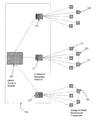
- FIG. 1 shows an exemplary storage network environment which includes a storage management platform, and in which it may be desirable to detect changes using component interaction modules;
- FIG. 2 is a simplified flow diagram for the process of discovering changes in the storage network environment
- FIG. 3 depicts an exemplary storage network environment in which it is desirable to resolve the host names of components within the storage network
- FIG. 4 is a simplified flow diagram for the process of resolving host names in the storage network environment.
- the systems and methods in various embodiments, provides, among other things, processes for efficient change discovery and host name resolution in storage network environments.
- the following detailed description of the embodiments refers to the accompanying drawings.
- SAN Storage Area Network
- the various embodiments set out below are merely provided for the purposes of illustrating certain embodiments of these systems and methods and for describing examples of such systems and methods. It will be apparent to those of skill in the art that the systems and methods described herein may, in certain forms, be employed in other types of networks and other storage network environments.
- a SAN or storage network environment is a network dedicated to enabling multiple applications on multiple hosts to access, i.e., read and write, data which is stored on multiple shared storage devices.
- a SAN consists of SAN devices, for example, different types of switches, which are interlinked, and is based on a number of possible transfer protocols such as Fiber Channel and iSCSI.
- Each server is connected to a SAN with one or more network cards, for example, an HBA.
- Application data is stored as data objects on storage devices in storage units e.g. LUNs.
- a storage network environment comprises various types of components such as interconnected network components and storage device components.
- Such storage network environments enable applications that are executed on hosts to store and retrieve data which are stored on any of the storage devices in the environment.
- FIG. 1 depicts an exemplary storage area network environment.
- component 121 may be a network switch to which a host is connected, and on which an application A is executed.
- Component 122 may also be a network switch which may be connected to 121 via one of its data ports, and which is also connected to storage device 123 , on which data volumes are stored including one which is associated with application A.
- each component in the storage network environment has a state, i.e., an internal execution state or configuration state, which may be configured to customize the function of that component.
- the internal execution state or configuration state of each component at each point of time contains values for various execution state variables (such as for example amount of data that flowed through a certain port in a recent interval) as well as configuration state variables, such as which ports are enabled, which other component is connected via each ports, what are the set transfer rates, which zones are defined for that component, which components are members of a particular zone, etc. Changes to these execution state variables occur as a result of data flow related activities, whereas changes to the configuration state variables occur as a result of planned or unplanned configuration actions.
- the internal state of each component, and the connectivity between the components may change as a result of planned changes, unplanned changes, malicious attacks, random failures, etc. State changes encompass changes which may impact the level of storage network environment service provided to applications operating within that network environment.
- a zone may be defined for switch 122 , and members added or removed from that zone such that data flow may be enabled or disabled through switch 122 i.e. data flow may be enabled or disabled between application A and its data volume on storage device 123 .
- the sequence of components between an application on a host and one of its data objects stored on a storage device, their types, attributes, state set up, and connectivity between them determine the level of storage service provided to that application. That level of service includes, for example, aspects of performance and availability for data flow.
- An access path between an application on a host and a data object on a storage device may be a sequence of components as described above which are set to enable information flow between the application flow on the host and the data object on the storage device. Attributes associated with each such end-to-end access path determine the level of storage service provided to that application.
- these components may form an access path between A and its volume on data storage device 123 .
- the individual characteristics of components 121 , 122 , and 123 , and of the links between them determines the end-to-end performance attribute of that access path.
- the existence of an independent route by which data may flow from A to the data volume on data storage device 123 determines the level of end-to-end redundancy and so the end-to-end availability attribute of that access path.
- the information described above is correlated and analyzed by mapping to an abstract graph-model representation in which each node represent a component and links between nodes represent connectivity between components and internal or configuration state information in each component.
- Data flow between 2 nodes in the graph is deemed possible if and only if there exists an access path between the 2 nodes in the model representation, and the attributes of that data flow are determined by the attributes of the different nodes and links associated with that path. If an access path exists between 2 nodes in the graph, or, if it is desired that an access path exist between 2 nodes in a graph, these 2 nodes may be called end nodes.
- logical access paths may be derived or identified in this manner and an abstract graph representation of the SAN may be constructed.
- the connection and configuration state information from each of the devices may be used in an aggregated process to generate an abstract graph representation of the network representing the logical access paths in the SAN.
- Each SAN device may be represented as a node in the graph.
- End-nodes represent applications/servers (source end-points) and storage/data objects e.g. LUNs (target end-points).
- each edge between nodes represents an existing physical link between the SAN devices (or between a SAN device and a SAN end-points).
- edges are eliminated in each case of a logical constraint, as defined in a device configuration, which disable flows on that link.
- the result of this iterative construction is an abstraction in which a logical access path between one application on a server and a data object e.g. LUN on a storage device exists if and only if a path exist in the abstract graph between the corresponding end nodes.
- An intermediate node is a node that is connected to two or more end nodes.
- the iterative step of graph edge elimination or pruning based on logical constraints implied by device configuration set-up is performed in a order designed to achieve as much pruning as early as possible.
- SAN semantics are utilized to determine the order in which device constraints are considered. For example, a LUN masking constraints on one device which constraints most of the potential flows along the physical paths, may be used to prune the graph before a zoning constraint on another which restricts a smaller number of flows.
- access path attributes are computed for each of the existing logical access paths according to the required attributes values specified in the logical access paths policy.
- the attribute values include, inter alia: level of end-to-end redundancy; type of redundancy; number of hops; and number of allocated ports.
- the “level of end-to-end redundancy” attribute value is computed by determining the number of graph paths between the given end-points which are independent—that is do not traverse through any joint intermediate device, for example, whether each intermediate device is associated with different SAN fabrics.
- the algorithm used is an adaptation of known graph algorithms such as the BFS and Graph Coloring algorithms to this particular problem applied to reflect typical SAN topology characteristics for optimized execution time.
- the resulting algorithm is efficient and has a computational complexity of O(N 2 ), where N is the number of components in the storage network environment.
- the “number of hops” attribute of a logical access path is the number of intermediate nodes in the constructed abstract graph.
- the “number of allocated ports” attribute for a given access path is determined from port allocation information obtained from the devices corresponding to the abstract graph.
- each change may affect any number of access paths and any of their end-to-end attributes, such access path analysis needs to be performed continuously to achieve appropriate storage service levels for applications at all times.
- a zoning update on 122 may result in a new access path which enable a flow between A and another volume on 123 or on a different storage device.
- a failure of switch 121 may eliminate the access path between A and its volume, and disrupt the possibility of a corresponding data flow.
- 100 depicts a storage management platform (SMP), and the end-to-end analysis of the access paths and attributes may be performed by the Global Analyzer module 105 .
- SMP storage management platform
- Several component interaction modules (CIMs), modules 110 , 111 , 112 interact with a number of storage environment components and provide the Global Analyzer module with information filtered in a way which enables the Global Analyzer to perform the required end-to-end access path analysis continuously, but which limits the amount of information delivered to that Global Analyzer, thereby improving the efficiency and scalability of the method.
- CCMs component interaction modules
- Each Component Interaction Module (CIM) 110 , 111 , or 112 is designated to interact with a sub-domain in the storage network environment consisting of one or more storage components C i , where i is an index representing a component, such that the CIMS are connected to all the components in the environment.
- Each CIM periodically receives state updates from each of components C i designated to it. That state update may be in response to a request initiated by the CIM, or a polling request, or may be unsolicited update from C i .
- the state S N that may be sent in each update from C i to CIM includes the designated subset of the state of C i , which includes all the state variables within the state S N that have been pre-selected, including, for example, the component identifiers (IDs) of other components currently connected to that component.
- IDs component identifiers
- Each CIM has an internal state in which it stores information locally, that is, on the CIM itself.
- Each component C has an internal state which may also be stored locally, that is, on the component C i itself.
- a hash function may be any function that maps an input value of any size to a unique output value which is much smaller in size, such that the probability of having the same function output for different function inputs is sufficiently low. Examples of such functions include CRC functions, SHA functions, or any other cryptographic one-way function.
- a hash function F(.) may be used to determine if a state of a component C i has changed since the last update.
- a CIM 110 , 111 , or 112 in FIG. 1 ) computes hash function value F(S N ) and compares it to the most-recently locally-stored hash function value F(S N ′) which was computed for C i in the previous update.
- S N is the most-recently received state for and from component C i , such that F(S N ) is the most-recently computed hash function value for state S N .
- S N ′ is the most-recently locally-stored hash function value for state S N , although this value need not be stored locally.
- F(S N ) is so much shorter than S N implies that by storing only F(S N ) and comparing only F(S N ) to previous F(S N ′) the CIM decreases the amount of space needed to store the hash function value F(S N ′) as well as the amount of time needed to process each update message from each component C i .
- each CIM performs a process that comprises the steps depicted in FIG. 2 :
- Step 201 selection for each type of component type the subset of state (or a state variable) to be tracked. That subset of states, i.e., a set of state variables, will include values for state variables which are selected by a combination of two main criteria:
- a selected state variable in a switch component, may be the member of a zone, and in a storage device component a selected value may be the WWN associated with a LUN-masking.
- a selected value may change and may cause access paths to be created, or to be terminated, or to change their access path attributes and so may directly affect the storage service levels of one or more applications.
- state variables may be expected to change only as a result of specific configuration changes, and so under normal circumstances may be expected to change relatively infrequently.
- state variables representing the actual level of data traffic flowing through particular ports on a switch, or through ports of a storage device, are expected to fluctuate quite rapidly, and so will normally not be selected.
- a fluctuation threshold may be pre-selected such that only states which change relatively frequently are selected, while states that do change relatively frequently are not selected.
- Step 202 Periodically, each CIM ( 110 , 111 , or 112 in FIG. 1 ) receives from each C i in its domain an update containing [C i , S N . T N ].
- C i represents the unique component identifier (ID) of the storage component
- S N represents the set of values of the attributes selected in step 201
- T N represents the timestamp corresponding to the point in time at C i in which S N was generated.
- Each update from each C i to the CIM may be generated either as a response to a request message from the CIM, i.e., by a polling request, or generated unilaterally by the C i either periodically or as a result of some internal event at the component, i.e., by an unsolicited update.
- an update message from a storage network switch may include the switch unique identifier as C i , the status of all the zones and members defined at this switch at the point of the update generation, and T N include the time at the point of the update generation.
- Step 206 If Y is not equal to Y′ then store [C i , S N . T N ] and forward to Global Analyzer 105 of FIG. 1 the update message [C i , S N . T N ].
- the specification of the function F(.) implies that with very high probability S N may be different than the S N ′ of the previous update, and so that there has been at one or more changes to the state since the last update from C i .
- the new state may be passed on to the Global Analyzer 105 of FIG. 1 to determine which state or subset of states for component C i has been changed and what are the implications as far as access paths and service levels.
- C i is a storage network switch a member may have been added to a zone on the switch, and so the new zone membership information will thus constitute a new different value for S N and so a new different value for Y.
- Such a change may be significant from the perspective of the Global Analyzer 105 of FIG. 1 because such an addition to a zone could imply that a new access path has been set up (which may or may not be consistent with the service level requirements of the corresponding applications).
- the updated state information is forwarded to the Global Analyzer 105 of FIG. 1 only if the associated timestamp T N of the update message represents a later time than the most-recently stored associated timestamp.
- Step 207 If Y equals Y′, then no update message is sent to the Global Analyzer. If no new update message is received from C i within an interval of time t after it was expected then send the Global Analyzer 105 of FIG. 1 an update message [C i , suspected down, TS], where TS is the timestamp representing the point in time in which this message was generated.
- the above scheme may be more effective the lower the percentage of update messages to the CIM ( 110 , 111 , or 112 in FIG. 1 ) that get forwarded to the Global Analyzer. That is, the more stable the selected values constituting the respective S from the various components, the less they change between update messages, and the fewer the number of updates that are sent to the Global Analyzer. Conversely, any change, even a small one to any of the attributes value, require resending the whole of S to the global analyzer.
- S N may be split into segments S 1 , S 2 , . . . S n .
- the function F( ) is then used to compute and store the corresponding Y 1 , Y 2 , . . . , Y n .
- each update message is arrived to the CIM ( 110 , 111 , or 112 in FIG. 1 ) from C i all the n respective values are computed, compared to the corresponding previous value and only these that have changed are forwarded to the Global Analyzer 105 of FIG. 1 in the following format: [ C i ,i,S i , . . . ,S j ,j,TS] (EQ. 1) where S i and S j are the state segments that were determined by CIM to have changes after computing Yi and Yj, and where TS is the timestamp at which this information is forwarded to the Global Analyzer 105 of FIG. 1 .
- the CIM ( 110 , 111 , or 112 in FIG. 1 ) computes Z and compares it to Z′ the previously stored value. Only if the values are different then a comparison of the individual Y 1 , Y 2 , . . . Y n may be performed and the corresponding ones that have changes are forwarded to the Global Analyzer 105 of FIG. 1 as specified above.
- each host may be identified by its storage network identifier such as for example the world-wide name (WWN) associated with any of its connected HBA storage network interface cards.
- WWN world-wide name
- a host may be identified by a different unique host-name identifier.
- FIG. 3 depicts an exemplary storage network environment.
- Host 350 interacts with storage networks components (e.g. switches 360 and 361 ) via 2 HBA cards 355 and 356 each with a designated WWN identifier. That host 350 is also connected to other external networks (such as for example internal or external IP networks such as 340 ) and may be identified in these environment by a different host name identifier.
- storage networks components e.g. switches 360 and 361
- 2 HBA cards 355 and 356 each with a designated WWN identifier.
- That host 350 is also connected to other external networks (such as for example internal or external IP networks such as 340 ) and may be identified in these environment by a different host name identifier.
- other external networks such as for example internal or external IP networks such as 340
- FIG. 3 also depicts a Storage Management Platform (SMP) system ( 310 ) which may interact with the different components in the environment.
- This SMP corresponds to SMP 100 in FIG. 1 .
- the SMP includes internally as sub-components, among others, the CIMS and Global Analyzer described above ( 110 - 112 and 105 , respectively, in FIG. 1 )
- mapping it may be desirable to perform that mapping automatically in environments that contain a large number of hosts and which are quite dynamic.
- the HBA cards and their corresponding WWNs may be occasionally swapped between hosts, and hosts may occasionally be migrated and re-connected to different storage network components.
- mapping because of manageability and scalability reasons it may be desirable to achieve that mapping without requiring any designated code or agents to be executing on the hosts, and without requiring any management interactions with the hosts themselves.
- no host agents are required, i.e., no designated code needs to be executed on the hosts, and thus the host name resolution may be based on management interactions only with the storage network components, as depicted in the flow chart in FIG. 4 :
- Step 401 Periodically, i.e. at discrete time intervals, the Storage Management Platform (SMP) receives from each component C i an update message containing its state S N . All access paths and corresponding attributes are derived and updated internally by the SMP. Optionally, this information may be stored by the SMP.
- SMP Storage Management Platform
- the SMP may derive the access path starting with host 350 and comprising of components 355 , 360 , and 370 .
- Step 402 For each derived access path which starts with a host associated with its storage network identifier (for example the WWN of its HBA), analyze the state S N for each component on that access path and determine the sub-state s of S N which may be associated with that access path. For example, host names are often embedded within corresponding switch zone names, or storage device LUN-masking for manageability reasons.
- a host associated with its storage network identifier for example the WWN of its HBA
- Step 403 For each sub-state, parse the strings to obtain a candidate host name or Host Candidate Name (HCN).
- HCN Host Candidate Name
- a zone name convention may be to generate a zone name from a concatenation of a few fields such switch name, host name, and fabric name.
- the string processing may strip away the additional fields and derive the host candidate name from within the concatenation constituting the zone name.
- Step 404 Send a query which include the HCN to a global name server, such as a Domain Name Server or DNS to determine if the HCN is included as a host name within that database.
- a global name server such as a Domain Name Server or DNS to determine if the HCN is included as a host name within that database.
- Step 405 Receive a response from the global name server to the query with the HCN. If the response indicates that the HCN may not be recognized as a host name, then perform again step 403 to obtain another HCN′ from sub-state s or from other state of components in that access path. Potentially perform again step 402 to obtain other HCNs from state of components in other access paths associated with the same host.
- Step 406 If the response from the global name server (e.g. DNS) indicates that the HCN is recognized as a host name, then store internally the mapping between the host, its storage network environment identifier (e.g. WWN) and its host name (the confirmed HCN). Include that mapping in appropriate storage network environment reports. Optionally require additional external re-confirmation for the established mapping e.g. from an external network or user.
- the global name server e.g. DNS
Abstract
Description
-
- the value of the selected state variablemay have a direct impact on an application access path, or an application access path attribute, and so may directly affect the corresponding level of storage service to an application;
- the value of the selected state variable is relatively stable—the value changes only as a result of significant configuration changes and not as a result of random traffic variations
[C i ,i,S i , . . . ,S j ,j,TS] (EQ. 1)
where Si and Sj are the state segments that were determined by CIM to have changes after computing Yi and Yj, and where TS is the timestamp at which this information is forwarded to the
Claims (8)
Priority Applications (1)
| Application Number | Priority Date | Filing Date | Title |
|---|---|---|---|
| US11/965,392 US8826032B1 (en) | 2006-12-27 | 2007-12-27 | Systems and methods for network change discovery and host name resolution in storage network environments |
Applications Claiming Priority (2)
| Application Number | Priority Date | Filing Date | Title |
|---|---|---|---|
| US87723006P | 2006-12-27 | 2006-12-27 | |
| US11/965,392 US8826032B1 (en) | 2006-12-27 | 2007-12-27 | Systems and methods for network change discovery and host name resolution in storage network environments |
Publications (1)
| Publication Number | Publication Date |
|---|---|
| US8826032B1 true US8826032B1 (en) | 2014-09-02 |
Family
ID=51400175
Family Applications (1)
| Application Number | Title | Priority Date | Filing Date |
|---|---|---|---|
| US11/965,392 Active 2031-11-18 US8826032B1 (en) | 2006-12-27 | 2007-12-27 | Systems and methods for network change discovery and host name resolution in storage network environments |
Country Status (1)
| Country | Link |
|---|---|
| US (1) | US8826032B1 (en) |
Cited By (70)
| Publication number | Priority date | Publication date | Assignee | Title |
|---|---|---|---|---|
| US20140372554A1 (en) * | 2013-06-14 | 2014-12-18 | Disney Enterprises, Inc. | Efficient synchronization of behavior trees using network significant nodes |
| US20150172415A1 (en) * | 2007-06-29 | 2015-06-18 | Amazon Technologies, Inc. | Request routing utilizing client location information |
| US20150358209A1 (en) * | 2014-06-06 | 2015-12-10 | Microsoft Corporation | Network-state management service |
| US20160173602A1 (en) * | 2014-12-12 | 2016-06-16 | International Business Machines Corporation | Clientless software defined grid |
| US20160182623A1 (en) * | 2014-12-17 | 2016-06-23 | Apriva, Llc | System and method for optimizing web service availability with a node group agreement protocol |
| US20160191330A1 (en) * | 2014-12-30 | 2016-06-30 | Emc Corporation | Passive san discovery |
| US9602351B2 (en) | 2014-06-06 | 2017-03-21 | Microsoft Technology Licensing, Llc | Proactive handling of network faults |
| US9712325B2 (en) | 2009-09-04 | 2017-07-18 | Amazon Technologies, Inc. | Managing secure content in a content delivery network |
| US9734472B2 (en) | 2008-11-17 | 2017-08-15 | Amazon Technologies, Inc. | Request routing utilizing cost information |
| US9742795B1 (en) | 2015-09-24 | 2017-08-22 | Amazon Technologies, Inc. | Mitigating network attacks |
| US9774619B1 (en) | 2015-09-24 | 2017-09-26 | Amazon Technologies, Inc. | Mitigating network attacks |
| US9787775B1 (en) | 2010-09-28 | 2017-10-10 | Amazon Technologies, Inc. | Point of presence management in request routing |
| US9787599B2 (en) | 2008-11-17 | 2017-10-10 | Amazon Technologies, Inc. | Managing content delivery network service providers |
| US9794216B2 (en) | 2010-09-28 | 2017-10-17 | Amazon Technologies, Inc. | Request routing in a networked environment |
| US9794281B1 (en) | 2015-09-24 | 2017-10-17 | Amazon Technologies, Inc. | Identifying sources of network attacks |
| US9800539B2 (en) | 2010-09-28 | 2017-10-24 | Amazon Technologies, Inc. | Request routing management based on network components |
| US9819567B1 (en) | 2015-03-30 | 2017-11-14 | Amazon Technologies, Inc. | Traffic surge management for points of presence |
| US9832141B1 (en) | 2015-05-13 | 2017-11-28 | Amazon Technologies, Inc. | Routing based request correlation |
| US9887915B2 (en) | 2008-03-31 | 2018-02-06 | Amazon Technologies, Inc. | Request routing based on class |
| US9887931B1 (en) | 2015-03-30 | 2018-02-06 | Amazon Technologies, Inc. | Traffic surge management for points of presence |
| US9887878B2 (en) | 2014-06-06 | 2018-02-06 | Microsoft Technology Licensing, Llc | Dynamic scheduling of network updates |
| US9887932B1 (en) | 2015-03-30 | 2018-02-06 | Amazon Technologies, Inc. | Traffic surge management for points of presence |
| US9894168B2 (en) | 2008-03-31 | 2018-02-13 | Amazon Technologies, Inc. | Locality based content distribution |
| US9893957B2 (en) | 2009-10-02 | 2018-02-13 | Amazon Technologies, Inc. | Forward-based resource delivery network management techniques |
| US9912740B2 (en) | 2008-06-30 | 2018-03-06 | Amazon Technologies, Inc. | Latency measurement in resource requests |
| US9929959B2 (en) | 2013-06-04 | 2018-03-27 | Amazon Technologies, Inc. | Managing network computing components utilizing request routing |
| US9930131B2 (en) | 2010-11-22 | 2018-03-27 | Amazon Technologies, Inc. | Request routing processing |
| US9985927B2 (en) | 2008-11-17 | 2018-05-29 | Amazon Technologies, Inc. | Managing content delivery network service providers by a content broker |
| US9992086B1 (en) | 2016-08-23 | 2018-06-05 | Amazon Technologies, Inc. | External health checking of virtual private cloud network environments |
| US10015241B2 (en) | 2012-09-20 | 2018-07-03 | Amazon Technologies, Inc. | Automated profiling of resource usage |
| US10033691B1 (en) | 2016-08-24 | 2018-07-24 | Amazon Technologies, Inc. | Adaptive resolution of domain name requests in virtual private cloud network environments |
| US10049051B1 (en) | 2015-12-11 | 2018-08-14 | Amazon Technologies, Inc. | Reserved cache space in content delivery networks |
| US10075551B1 (en) | 2016-06-06 | 2018-09-11 | Amazon Technologies, Inc. | Request management for hierarchical cache |
| US10097566B1 (en) | 2015-07-31 | 2018-10-09 | Amazon Technologies, Inc. | Identifying targets of network attacks |
| US10110694B1 (en) | 2016-06-29 | 2018-10-23 | Amazon Technologies, Inc. | Adaptive transfer rate for retrieving content from a server |
| US10225362B2 (en) | 2012-06-11 | 2019-03-05 | Amazon Technologies, Inc. | Processing DNS queries to identify pre-processing information |
| US10225326B1 (en) | 2015-03-23 | 2019-03-05 | Amazon Technologies, Inc. | Point of presence based data uploading |
| US10257307B1 (en) | 2015-12-11 | 2019-04-09 | Amazon Technologies, Inc. | Reserved cache space in content delivery networks |
| US10270878B1 (en) | 2015-11-10 | 2019-04-23 | Amazon Technologies, Inc. | Routing for origin-facing points of presence |
| US10348639B2 (en) | 2015-12-18 | 2019-07-09 | Amazon Technologies, Inc. | Use of virtual endpoints to improve data transmission rates |
| US10372499B1 (en) | 2016-12-27 | 2019-08-06 | Amazon Technologies, Inc. | Efficient region selection system for executing request-driven code |
| US10425290B1 (en) * | 2018-12-13 | 2019-09-24 | LogicMonitor, Inc. | Creating and displaying a graph representation of a computer network topology for an executing application |
| US10447648B2 (en) | 2017-06-19 | 2019-10-15 | Amazon Technologies, Inc. | Assignment of a POP to a DNS resolver based on volume of communications over a link between client devices and the POP |
| US10469513B2 (en) | 2016-10-05 | 2019-11-05 | Amazon Technologies, Inc. | Encrypted network addresses |
| US10503613B1 (en) | 2017-04-21 | 2019-12-10 | Amazon Technologies, Inc. | Efficient serving of resources during server unavailability |
| US10506029B2 (en) | 2010-01-28 | 2019-12-10 | Amazon Technologies, Inc. | Content distribution network |
| US10511567B2 (en) | 2008-03-31 | 2019-12-17 | Amazon Technologies, Inc. | Network resource identification |
| US10521348B2 (en) | 2009-06-16 | 2019-12-31 | Amazon Technologies, Inc. | Managing resources using resource expiration data |
| US10554749B2 (en) | 2014-12-12 | 2020-02-04 | International Business Machines Corporation | Clientless software defined grid |
| US10592578B1 (en) | 2018-03-07 | 2020-03-17 | Amazon Technologies, Inc. | Predictive content push-enabled content delivery network |
| US10623408B1 (en) | 2012-04-02 | 2020-04-14 | Amazon Technologies, Inc. | Context sensitive object management |
| US10645056B2 (en) | 2012-12-19 | 2020-05-05 | Amazon Technologies, Inc. | Source-dependent address resolution |
| US10645149B2 (en) | 2008-03-31 | 2020-05-05 | Amazon Technologies, Inc. | Content delivery reconciliation |
| US10728133B2 (en) | 2014-12-18 | 2020-07-28 | Amazon Technologies, Inc. | Routing mode and point-of-presence selection service |
| US10742550B2 (en) | 2008-11-17 | 2020-08-11 | Amazon Technologies, Inc. | Updating routing information based on client location |
| US10778554B2 (en) | 2010-09-28 | 2020-09-15 | Amazon Technologies, Inc. | Latency measurement in resource requests |
| US10831549B1 (en) | 2016-12-27 | 2020-11-10 | Amazon Technologies, Inc. | Multi-region request-driven code execution system |
| US10862852B1 (en) | 2018-11-16 | 2020-12-08 | Amazon Technologies, Inc. | Resolution of domain name requests in heterogeneous network environments |
| US10931738B2 (en) | 2010-09-28 | 2021-02-23 | Amazon Technologies, Inc. | Point of presence management in request routing |
| US10938884B1 (en) | 2017-01-30 | 2021-03-02 | Amazon Technologies, Inc. | Origin server cloaking using virtual private cloud network environments |
| US10958501B1 (en) | 2010-09-28 | 2021-03-23 | Amazon Technologies, Inc. | Request routing information based on client IP groupings |
| US11025747B1 (en) | 2018-12-12 | 2021-06-01 | Amazon Technologies, Inc. | Content request pattern-based routing system |
| US11075987B1 (en) | 2017-06-12 | 2021-07-27 | Amazon Technologies, Inc. | Load estimating content delivery network |
| US11108729B2 (en) | 2010-09-28 | 2021-08-31 | Amazon Technologies, Inc. | Managing request routing information utilizing client identifiers |
| US11194719B2 (en) | 2008-03-31 | 2021-12-07 | Amazon Technologies, Inc. | Cache optimization |
| US11290418B2 (en) | 2017-09-25 | 2022-03-29 | Amazon Technologies, Inc. | Hybrid content request routing system |
| US11336712B2 (en) | 2010-09-28 | 2022-05-17 | Amazon Technologies, Inc. | Point of presence management in request routing |
| US11604667B2 (en) | 2011-04-27 | 2023-03-14 | Amazon Technologies, Inc. | Optimized deployment based upon customer locality |
| US11671329B2 (en) | 2018-04-04 | 2023-06-06 | Arista Networks, Inc. | Computation of network flooding topologies |
| US11743097B2 (en) * | 2015-06-22 | 2023-08-29 | Arista Networks, Inc. | Method and system for sharing state between network elements |
Citations (87)
| Publication number | Priority date | Publication date | Assignee | Title |
|---|---|---|---|---|
| US5043866A (en) | 1988-04-08 | 1991-08-27 | International Business Machines Corporation | Soft checkpointing system using log sequence numbers derived from stored data pages and log records for database recovery |
| US5280611A (en) | 1991-11-08 | 1994-01-18 | International Business Machines Corporation | Method for managing database recovery from failure of a shared store in a system including a plurality of transaction-based systems of the write-ahead logging type |
| US5327556A (en) | 1991-02-15 | 1994-07-05 | International Business Machines Corporation | Fast intersystem page transfer in a data sharing environment with record locking |
| US5381545A (en) | 1991-06-04 | 1995-01-10 | International Business Machines Corporation | Data backup and recovery in a data processing system |
| US5586250A (en) | 1993-11-12 | 1996-12-17 | Conner Peripherals, Inc. | SCSI-coupled module for monitoring and controlling SCSI-coupled raid bank and bank environment |
| US5684967A (en) | 1995-09-13 | 1997-11-04 | International Business Machines Corporation | System and method for generalized network topology representation |
| US5774377A (en) | 1991-07-30 | 1998-06-30 | Hewlett-Packard Company | Method and apparatus for monitoring a subsystem within a distributed system for providing an archive of events within a certain time of a trap condition |
| US5825772A (en) | 1995-11-15 | 1998-10-20 | Cabletron Systems, Inc. | Distributed connection-oriented services for switched communications networks |
| US5940819A (en) | 1997-08-29 | 1999-08-17 | International Business Machines Corporation | User specification of query access paths in a relational database management system |
| US6014673A (en) | 1996-12-05 | 2000-01-11 | Hewlett-Packard Company | Simultaneous use of database and durable store in work flow and process flow systems |
| US6223176B1 (en) | 1998-09-25 | 2001-04-24 | International Business Machines Corporation | Method and computer program product for implementing highly concurrent record insertion in an ordinal number dependent database |
| US6233240B1 (en) | 1998-10-27 | 2001-05-15 | Fujitsu Network Communications, Inc. | Event based rate policing with a jumping window |
| US6240463B1 (en) | 1998-11-24 | 2001-05-29 | Lucent Technologies Inc. | Router placement methods and apparatus for designing IP networks with performance guarantees |
| WO2001082077A2 (en) | 2000-04-20 | 2001-11-01 | Ciprico Inc. | Method and apparatus for monitoring network appliances |
| US20010047482A1 (en) | 2000-01-20 | 2001-11-29 | Harris Gordon J. | Distributed storage resource management in a storage area network |
| US6327598B1 (en) | 1997-11-24 | 2001-12-04 | International Business Machines Corporation | Removing a filled-out form from a non-interactive web browser cache to an interactive web browser cache |
| US6347335B1 (en) | 1995-09-22 | 2002-02-12 | Emc Corporation | System using a common and local event logs for logging event information generated by plurality of devices for determining problem in storage access operations |
| US6434626B1 (en) | 1999-01-14 | 2002-08-13 | Compaq Information Technologies Group, L.P. | Method and apparatus for low latency network performance monitoring |
| US20020145981A1 (en) | 2001-04-10 | 2002-10-10 | Eric Klinker | System and method to assure network service levels with intelligent routing |
| WO2002088947A2 (en) | 2001-04-25 | 2002-11-07 | Sun Microsystems, Inc. | Maintaining fabric device configuration through dynamic reconfiguration |
| US20030005119A1 (en) | 2001-06-28 | 2003-01-02 | Intersan, Inc., A Delaware Corporation | Automated creation of application data paths in storage area networks |
| US20030018619A1 (en) | 2001-06-22 | 2003-01-23 | International Business Machines Corporation | System and method for granular control of message logging |
| US20030033346A1 (en) | 2001-08-10 | 2003-02-13 | Sun Microsystems, Inc. | Method, system, and program for managing multiple resources in a system |
| US20030033398A1 (en) | 2001-08-10 | 2003-02-13 | Sun Microsystems, Inc. | Method, system, and program for generating and using configuration policies |
| US20030055932A1 (en) | 2001-09-19 | 2003-03-20 | Dell Products L.P. | System and method for configuring a storage area network |
| WO2003054711A1 (en) | 2001-09-21 | 2003-07-03 | Polyserve, Inc. | A system and method for management of a storage area network |
| US20030131077A1 (en) | 2002-01-04 | 2003-07-10 | Dirk Hogan | Efficient validation of network configuration change commands |
| US20030191992A1 (en) | 2002-04-05 | 2003-10-09 | International Business Machines Corporation | Distributed fault detection for data storage networks |
| US6636981B1 (en) | 2000-01-06 | 2003-10-21 | International Business Machines Corporation | Method and system for end-to-end problem determination and fault isolation for storage area networks |
| US20030208589A1 (en) * | 2001-12-07 | 2003-11-06 | Masayuki Yamamoto | Detecting configuration inconsistency in storage networks |
| US20030237017A1 (en) | 2002-06-24 | 2003-12-25 | Jibbe Mahmoud Khaled | Component fault isolation in a storage area network |
| US20040010787A1 (en) | 2002-07-11 | 2004-01-15 | Traut Eric P. | Method for forking or migrating a virtual machine |
| US20040019833A1 (en) | 2002-07-25 | 2004-01-29 | Riedl Daniel A. | Method for validating operation of a fibre link |
| US6691169B1 (en) | 2000-02-01 | 2004-02-10 | At&T Corp. | Method and apparatus for detecting route advertisement violations in a network of interconnected peers |
| US20040030768A1 (en) | 1999-05-25 | 2004-02-12 | Suban Krishnamoorthy | Unified system and method for downloading code to heterogeneous devices in distributed storage area networks |
| US20040075680A1 (en) | 2002-10-17 | 2004-04-22 | Brocade Communications Systems, Inc. | Method and apparatus for displaying network fabric data |
| US6751228B1 (en) | 1999-03-23 | 2004-06-15 | Yamaha Corporation | Packet handler of audio data by isochronous mode |
| US6792503B2 (en) | 2000-12-06 | 2004-09-14 | Hitachi, Ltd. | Disk storage accessing system and method for changing access path to storage devices |
| US6795399B1 (en) | 1998-11-24 | 2004-09-21 | Lucent Technologies Inc. | Link capacity computation methods and apparatus for designing IP networks with performance guarantees |
| US6801949B1 (en) | 1999-04-12 | 2004-10-05 | Rainfinity, Inc. | Distributed server cluster with graphical user interface |
| US20040205089A1 (en) | 2002-10-23 | 2004-10-14 | Onaro | Method and system for validating logical end-to-end access paths in storage area networks |
| US20040215749A1 (en) | 2002-08-12 | 2004-10-28 | Tsao Sheng Ted Tai | Distributed virtual san |
| US6816927B2 (en) | 2002-02-07 | 2004-11-09 | Bull S.A. | Method and system for automatic updating an access path to the system disk of a hardware perimeter of computer |
| US20040243699A1 (en) | 2003-05-29 | 2004-12-02 | Mike Koclanes | Policy based management of storage resources |
| US20050010682A1 (en) | 2001-09-07 | 2005-01-13 | Shai Amir | Load balancing method for exchanging data between multiple hosts and storage entities, in ip based storage area network |
| US20050033757A1 (en) | 2001-08-31 | 2005-02-10 | Arkivio, Inc. | Techniques for performing policy automated operations |
| US20050044088A1 (en) | 2003-08-21 | 2005-02-24 | Lindsay Bruce G. | System and method for asynchronous data replication without persistence for distributed computing |
| US20050097471A1 (en) | 2001-07-19 | 2005-05-05 | Microsoft Corporation | Integrated timeline and logically-related list view |
| US20050114403A1 (en) | 2003-11-21 | 2005-05-26 | Charles Atchison | Methods, systems and computer program products for monitoring files |
| US6904143B1 (en) | 2001-03-05 | 2005-06-07 | Verizon Corporate Services Group Inc. | Apparatus and method for logging events that occur when interacting with an automated call center system |
| US6909700B1 (en) | 1998-11-24 | 2005-06-21 | Lucent Technologies Inc. | Network topology optimization methods and apparatus for designing IP networks with performance guarantees |
| US20050160431A1 (en) | 2002-07-29 | 2005-07-21 | Oracle Corporation | Method and mechanism for debugging a series of related events within a computer system |
| US20050256961A1 (en) | 2002-10-23 | 2005-11-17 | Roee Alon | Methods and systems for predictive change management for access paths in networks |
| US20050262233A1 (en) | 2002-10-23 | 2005-11-24 | Roee Alon | Methods and systems for history analysis for access paths in networks |
| US20060004830A1 (en) | 2004-06-07 | 2006-01-05 | Lora Brian M | Agent-less systems, methods and computer program products for managing a plurality of remotely located data storage systems |
| US6985937B1 (en) | 2000-05-11 | 2006-01-10 | Ensim Corporation | Dynamically modifying the resources of a virtual server |
| US20060106938A1 (en) * | 2003-11-14 | 2006-05-18 | Cisco Systems, Inc. | Load balancing mechanism using resource availability profiles |
| US7051029B1 (en) | 2001-01-05 | 2006-05-23 | Revenue Science, Inc. | Identifying and reporting on frequent sequences of events in usage data |
| US7062559B2 (en) | 2001-10-10 | 2006-06-13 | Hitachi,Ltd. | Computer resource allocating method |
| US7069480B1 (en) | 2001-03-28 | 2006-06-27 | The Shoregroup, Inc. | Method and apparatus for identifying problems in computer networks |
| US20060143492A1 (en) | 2001-11-28 | 2006-06-29 | Leduc Douglas E | System and method for fault detection and recovery |
| US20060161884A1 (en) | 2005-01-18 | 2006-07-20 | Microsoft Corporation | Methods for managing capacity |
| US20060161883A1 (en) | 2005-01-18 | 2006-07-20 | Microsoft Corporation | Methods for capacity management |
| US7103712B2 (en) | 2002-12-11 | 2006-09-05 | Hitachi, Ltd. | iSCSI storage management method and management system |
| US7103653B2 (en) | 2000-06-05 | 2006-09-05 | Fujitsu Limited | Storage area network management system, method, and computer-readable medium |
| US20060218366A1 (en) | 2005-03-28 | 2006-09-28 | Satoshi Fukuda | Data relocation method |
| US7120654B2 (en) | 2002-08-20 | 2006-10-10 | Veritas Operating Corporation | System and method for network-free file replication in a storage area network |
| US7127633B1 (en) | 2001-11-15 | 2006-10-24 | Xiotech Corporation | System and method to failover storage area network targets from one interface to another |
| US7149886B2 (en) | 2001-05-09 | 2006-12-12 | Hitachi, Ltd. | Computer system using disk controller and operating service thereof |
| US7194538B1 (en) | 2002-06-04 | 2007-03-20 | Veritas Operating Corporation | Storage area network (SAN) management system for discovering SAN components using a SAN management server |
| US20070088763A1 (en) | 2005-09-27 | 2007-04-19 | Raphael Yahalom | Methods and systems for validating accessibility and currency of replicated data |
| US20070094378A1 (en) | 2001-10-05 | 2007-04-26 | Baldwin Duane M | Storage Area Network Methods and Apparatus with Centralized Management |
| US20070112883A1 (en) | 2005-11-16 | 2007-05-17 | Hitachi, Ltd. | Computer system, managing computer and recovery management method |
| US20070169177A1 (en) * | 2005-09-16 | 2007-07-19 | Ntt Docomo, Inc. | Changing states of communication links in computer networks in an authenticated manner |
| US20070179985A1 (en) * | 2005-07-22 | 2007-08-02 | Michael Knowles | Method for detecting state changes between data stored in a first computing device and data retrieved from a second computing device |
| US20070192329A1 (en) | 2006-01-24 | 2007-08-16 | Citrix Systems, Inc. | Methods and systems for executing, by a virtual machine, an application program requested by a client machine |
| US7260628B2 (en) | 2002-09-06 | 2007-08-21 | Hitachi, Ltd. | Event notification in storage networks |
| US20070198722A1 (en) | 2005-12-19 | 2007-08-23 | Rajiv Kottomtharayil | Systems and methods for granular resource management in a storage network |
| US20070208920A1 (en) * | 2006-02-27 | 2007-09-06 | Tevis Gregory J | Apparatus, system, and method for dynamically determining a set of storage area network components for performance monitoring |
| US20080109822A1 (en) * | 2006-11-03 | 2008-05-08 | Ashmi Ashokkumar Chokshi | Detecting entity changes in a storage area network environment |
| US7376937B1 (en) | 2001-05-31 | 2008-05-20 | Oracle International Corporation | Method and mechanism for using a meta-language to define and analyze traces |
| US7380239B1 (en) | 2001-05-31 | 2008-05-27 | Oracle International Corporation | Method and mechanism for diagnosing computer applications using traces |
| US20080155208A1 (en) | 2006-12-21 | 2008-06-26 | Hiltgen Daniel K | Securing Virtual Machine Data |
| US20080155223A1 (en) | 2006-12-21 | 2008-06-26 | Hiltgen Daniel K | Storage Architecture for Virtual Machines |
| US7403987B1 (en) * | 2001-06-29 | 2008-07-22 | Symantec Operating Corporation | Transactional SAN management |
| US20080189700A1 (en) | 2007-02-02 | 2008-08-07 | Vmware, Inc. | Admission Control for Virtual Machine Cluster |
| US20090172666A1 (en) | 2007-12-31 | 2009-07-02 | Netapp, Inc. | System and method for automatic storage load balancing in virtual server environments |
-
2007
- 2007-12-27 US US11/965,392 patent/US8826032B1/en active Active
Patent Citations (94)
| Publication number | Priority date | Publication date | Assignee | Title |
|---|---|---|---|---|
| US5043866A (en) | 1988-04-08 | 1991-08-27 | International Business Machines Corporation | Soft checkpointing system using log sequence numbers derived from stored data pages and log records for database recovery |
| US5327556A (en) | 1991-02-15 | 1994-07-05 | International Business Machines Corporation | Fast intersystem page transfer in a data sharing environment with record locking |
| US5381545A (en) | 1991-06-04 | 1995-01-10 | International Business Machines Corporation | Data backup and recovery in a data processing system |
| US5774377A (en) | 1991-07-30 | 1998-06-30 | Hewlett-Packard Company | Method and apparatus for monitoring a subsystem within a distributed system for providing an archive of events within a certain time of a trap condition |
| US5280611A (en) | 1991-11-08 | 1994-01-18 | International Business Machines Corporation | Method for managing database recovery from failure of a shared store in a system including a plurality of transaction-based systems of the write-ahead logging type |
| US5586250A (en) | 1993-11-12 | 1996-12-17 | Conner Peripherals, Inc. | SCSI-coupled module for monitoring and controlling SCSI-coupled raid bank and bank environment |
| US5684967A (en) | 1995-09-13 | 1997-11-04 | International Business Machines Corporation | System and method for generalized network topology representation |
| US6347335B1 (en) | 1995-09-22 | 2002-02-12 | Emc Corporation | System using a common and local event logs for logging event information generated by plurality of devices for determining problem in storage access operations |
| US5825772A (en) | 1995-11-15 | 1998-10-20 | Cabletron Systems, Inc. | Distributed connection-oriented services for switched communications networks |
| US6014673A (en) | 1996-12-05 | 2000-01-11 | Hewlett-Packard Company | Simultaneous use of database and durable store in work flow and process flow systems |
| US5940819A (en) | 1997-08-29 | 1999-08-17 | International Business Machines Corporation | User specification of query access paths in a relational database management system |
| US6327598B1 (en) | 1997-11-24 | 2001-12-04 | International Business Machines Corporation | Removing a filled-out form from a non-interactive web browser cache to an interactive web browser cache |
| US6223176B1 (en) | 1998-09-25 | 2001-04-24 | International Business Machines Corporation | Method and computer program product for implementing highly concurrent record insertion in an ordinal number dependent database |
| US6233240B1 (en) | 1998-10-27 | 2001-05-15 | Fujitsu Network Communications, Inc. | Event based rate policing with a jumping window |
| US6240463B1 (en) | 1998-11-24 | 2001-05-29 | Lucent Technologies Inc. | Router placement methods and apparatus for designing IP networks with performance guarantees |
| US6795399B1 (en) | 1998-11-24 | 2004-09-21 | Lucent Technologies Inc. | Link capacity computation methods and apparatus for designing IP networks with performance guarantees |
| US6909700B1 (en) | 1998-11-24 | 2005-06-21 | Lucent Technologies Inc. | Network topology optimization methods and apparatus for designing IP networks with performance guarantees |
| US6434626B1 (en) | 1999-01-14 | 2002-08-13 | Compaq Information Technologies Group, L.P. | Method and apparatus for low latency network performance monitoring |
| US6751228B1 (en) | 1999-03-23 | 2004-06-15 | Yamaha Corporation | Packet handler of audio data by isochronous mode |
| US6801949B1 (en) | 1999-04-12 | 2004-10-05 | Rainfinity, Inc. | Distributed server cluster with graphical user interface |
| US20040030768A1 (en) | 1999-05-25 | 2004-02-12 | Suban Krishnamoorthy | Unified system and method for downloading code to heterogeneous devices in distributed storage area networks |
| US6636981B1 (en) | 2000-01-06 | 2003-10-21 | International Business Machines Corporation | Method and system for end-to-end problem determination and fault isolation for storage area networks |
| US20010047482A1 (en) | 2000-01-20 | 2001-11-29 | Harris Gordon J. | Distributed storage resource management in a storage area network |
| US6691169B1 (en) | 2000-02-01 | 2004-02-10 | At&T Corp. | Method and apparatus for detecting route advertisement violations in a network of interconnected peers |
| WO2001082077A2 (en) | 2000-04-20 | 2001-11-01 | Ciprico Inc. | Method and apparatus for monitoring network appliances |
| US6985937B1 (en) | 2000-05-11 | 2006-01-10 | Ensim Corporation | Dynamically modifying the resources of a virtual server |
| US7103653B2 (en) | 2000-06-05 | 2006-09-05 | Fujitsu Limited | Storage area network management system, method, and computer-readable medium |
| US6792503B2 (en) | 2000-12-06 | 2004-09-14 | Hitachi, Ltd. | Disk storage accessing system and method for changing access path to storage devices |
| US7051029B1 (en) | 2001-01-05 | 2006-05-23 | Revenue Science, Inc. | Identifying and reporting on frequent sequences of events in usage data |
| US6904143B1 (en) | 2001-03-05 | 2005-06-07 | Verizon Corporate Services Group Inc. | Apparatus and method for logging events that occur when interacting with an automated call center system |
| US7069480B1 (en) | 2001-03-28 | 2006-06-27 | The Shoregroup, Inc. | Method and apparatus for identifying problems in computer networks |
| US20020145981A1 (en) | 2001-04-10 | 2002-10-10 | Eric Klinker | System and method to assure network service levels with intelligent routing |
| WO2002088947A2 (en) | 2001-04-25 | 2002-11-07 | Sun Microsystems, Inc. | Maintaining fabric device configuration through dynamic reconfiguration |
| US7149886B2 (en) | 2001-05-09 | 2006-12-12 | Hitachi, Ltd. | Computer system using disk controller and operating service thereof |
| US7376937B1 (en) | 2001-05-31 | 2008-05-20 | Oracle International Corporation | Method and mechanism for using a meta-language to define and analyze traces |
| US7380239B1 (en) | 2001-05-31 | 2008-05-27 | Oracle International Corporation | Method and mechanism for diagnosing computer applications using traces |
| US20030018619A1 (en) | 2001-06-22 | 2003-01-23 | International Business Machines Corporation | System and method for granular control of message logging |
| US20030005119A1 (en) | 2001-06-28 | 2003-01-02 | Intersan, Inc., A Delaware Corporation | Automated creation of application data paths in storage area networks |
| US7403987B1 (en) * | 2001-06-29 | 2008-07-22 | Symantec Operating Corporation | Transactional SAN management |
| US20050097471A1 (en) | 2001-07-19 | 2005-05-05 | Microsoft Corporation | Integrated timeline and logically-related list view |
| US20030033398A1 (en) | 2001-08-10 | 2003-02-13 | Sun Microsystems, Inc. | Method, system, and program for generating and using configuration policies |
| US20030033346A1 (en) | 2001-08-10 | 2003-02-13 | Sun Microsystems, Inc. | Method, system, and program for managing multiple resources in a system |
| US20050033757A1 (en) | 2001-08-31 | 2005-02-10 | Arkivio, Inc. | Techniques for performing policy automated operations |
| US20050010682A1 (en) | 2001-09-07 | 2005-01-13 | Shai Amir | Load balancing method for exchanging data between multiple hosts and storage entities, in ip based storage area network |
| US20030055932A1 (en) | 2001-09-19 | 2003-03-20 | Dell Products L.P. | System and method for configuring a storage area network |
| WO2003054711A1 (en) | 2001-09-21 | 2003-07-03 | Polyserve, Inc. | A system and method for management of a storage area network |
| US20070094378A1 (en) | 2001-10-05 | 2007-04-26 | Baldwin Duane M | Storage Area Network Methods and Apparatus with Centralized Management |
| US7062559B2 (en) | 2001-10-10 | 2006-06-13 | Hitachi,Ltd. | Computer resource allocating method |
| US7127633B1 (en) | 2001-11-15 | 2006-10-24 | Xiotech Corporation | System and method to failover storage area network targets from one interface to another |
| US20060143492A1 (en) | 2001-11-28 | 2006-06-29 | Leduc Douglas E | System and method for fault detection and recovery |
| US20030208589A1 (en) * | 2001-12-07 | 2003-11-06 | Masayuki Yamamoto | Detecting configuration inconsistency in storage networks |
| US7058702B2 (en) | 2002-01-04 | 2006-06-06 | Hewlett-Packard Development Company, L.P. | Efficient validation of network configuration change commands |
| US20030131077A1 (en) | 2002-01-04 | 2003-07-10 | Dirk Hogan | Efficient validation of network configuration change commands |
| US6816927B2 (en) | 2002-02-07 | 2004-11-09 | Bull S.A. | Method and system for automatic updating an access path to the system disk of a hardware perimeter of computer |
| US20030191992A1 (en) | 2002-04-05 | 2003-10-09 | International Business Machines Corporation | Distributed fault detection for data storage networks |
| US7194538B1 (en) | 2002-06-04 | 2007-03-20 | Veritas Operating Corporation | Storage area network (SAN) management system for discovering SAN components using a SAN management server |
| US20030237017A1 (en) | 2002-06-24 | 2003-12-25 | Jibbe Mahmoud Khaled | Component fault isolation in a storage area network |
| US20040010787A1 (en) | 2002-07-11 | 2004-01-15 | Traut Eric P. | Method for forking or migrating a virtual machine |
| US20040019833A1 (en) | 2002-07-25 | 2004-01-29 | Riedl Daniel A. | Method for validating operation of a fibre link |
| US20050160431A1 (en) | 2002-07-29 | 2005-07-21 | Oracle Corporation | Method and mechanism for debugging a series of related events within a computer system |
| US7512954B2 (en) | 2002-07-29 | 2009-03-31 | Oracle International Corporation | Method and mechanism for debugging a series of related events within a computer system |
| US20040215749A1 (en) | 2002-08-12 | 2004-10-28 | Tsao Sheng Ted Tai | Distributed virtual san |
| US7120654B2 (en) | 2002-08-20 | 2006-10-10 | Veritas Operating Corporation | System and method for network-free file replication in a storage area network |
| US7260628B2 (en) | 2002-09-06 | 2007-08-21 | Hitachi, Ltd. | Event notification in storage networks |
| US20040075680A1 (en) | 2002-10-17 | 2004-04-22 | Brocade Communications Systems, Inc. | Method and apparatus for displaying network fabric data |
| US7546333B2 (en) | 2002-10-23 | 2009-06-09 | Netapp, Inc. | Methods and systems for predictive change management for access paths in networks |
| US7617320B2 (en) | 2002-10-23 | 2009-11-10 | Netapp, Inc. | Method and system for validating logical end-to-end access paths in storage area networks |
| US20050262233A1 (en) | 2002-10-23 | 2005-11-24 | Roee Alon | Methods and systems for history analysis for access paths in networks |
| US20050256961A1 (en) | 2002-10-23 | 2005-11-17 | Roee Alon | Methods and systems for predictive change management for access paths in networks |
| US20040205089A1 (en) | 2002-10-23 | 2004-10-14 | Onaro | Method and system for validating logical end-to-end access paths in storage area networks |
| US20090313367A1 (en) | 2002-10-23 | 2009-12-17 | Netapp, Inc. | Methods and systems for predictive change management for access paths in networks |
| US7103712B2 (en) | 2002-12-11 | 2006-09-05 | Hitachi, Ltd. | iSCSI storage management method and management system |
| WO2004111765A2 (en) | 2003-05-29 | 2004-12-23 | Creekpath Systems, Inc. | Policy based management of storage resorces |
| US20040243699A1 (en) | 2003-05-29 | 2004-12-02 | Mike Koclanes | Policy based management of storage resources |
| US20050044088A1 (en) | 2003-08-21 | 2005-02-24 | Lindsay Bruce G. | System and method for asynchronous data replication without persistence for distributed computing |
| US20060106938A1 (en) * | 2003-11-14 | 2006-05-18 | Cisco Systems, Inc. | Load balancing mechanism using resource availability profiles |
| US20050114403A1 (en) | 2003-11-21 | 2005-05-26 | Charles Atchison | Methods, systems and computer program products for monitoring files |
| US20060004830A1 (en) | 2004-06-07 | 2006-01-05 | Lora Brian M | Agent-less systems, methods and computer program products for managing a plurality of remotely located data storage systems |
| US20060161884A1 (en) | 2005-01-18 | 2006-07-20 | Microsoft Corporation | Methods for managing capacity |
| US20060161883A1 (en) | 2005-01-18 | 2006-07-20 | Microsoft Corporation | Methods for capacity management |
| US20060218366A1 (en) | 2005-03-28 | 2006-09-28 | Satoshi Fukuda | Data relocation method |
| US20070179985A1 (en) * | 2005-07-22 | 2007-08-02 | Michael Knowles | Method for detecting state changes between data stored in a first computing device and data retrieved from a second computing device |
| US20070169177A1 (en) * | 2005-09-16 | 2007-07-19 | Ntt Docomo, Inc. | Changing states of communication links in computer networks in an authenticated manner |
| US20070088763A1 (en) | 2005-09-27 | 2007-04-19 | Raphael Yahalom | Methods and systems for validating accessibility and currency of replicated data |
| US20070112883A1 (en) | 2005-11-16 | 2007-05-17 | Hitachi, Ltd. | Computer system, managing computer and recovery management method |
| US20070198722A1 (en) | 2005-12-19 | 2007-08-23 | Rajiv Kottomtharayil | Systems and methods for granular resource management in a storage network |
| US20070192329A1 (en) | 2006-01-24 | 2007-08-16 | Citrix Systems, Inc. | Methods and systems for executing, by a virtual machine, an application program requested by a client machine |
| US20070208920A1 (en) * | 2006-02-27 | 2007-09-06 | Tevis Gregory J | Apparatus, system, and method for dynamically determining a set of storage area network components for performance monitoring |
| US20080109822A1 (en) * | 2006-11-03 | 2008-05-08 | Ashmi Ashokkumar Chokshi | Detecting entity changes in a storage area network environment |
| US20080155208A1 (en) | 2006-12-21 | 2008-06-26 | Hiltgen Daniel K | Securing Virtual Machine Data |
| US20080155223A1 (en) | 2006-12-21 | 2008-06-26 | Hiltgen Daniel K | Storage Architecture for Virtual Machines |
| US20080189468A1 (en) | 2007-02-02 | 2008-08-07 | Vmware, Inc. | High Availability Virtual Machine Cluster |
| US20080189700A1 (en) | 2007-02-02 | 2008-08-07 | Vmware, Inc. | Admission Control for Virtual Machine Cluster |
| US20090172666A1 (en) | 2007-12-31 | 2009-07-02 | Netapp, Inc. | System and method for automatic storage load balancing in virtual server environments |
Non-Patent Citations (11)
| Title |
|---|
| "Assurency: Comprehensive, Persistent Security for Storage Area Networks," Kasten Chase (2002). |
| "Information Lifecycle Management: An Automated Approach," Technical White Paper, EMC2 (Dec. 8, 2003). |
| "Kasten Chase Unveils Advanced Security Architecture," GRIDtoday, v.1, n. 18; www.gridtoday.com/02/101/100546.html, (Oct. 14, 2002), printed from Internet on Oct. 16, 2003. |
| "Radiant Data Server Technology Overview," White Paper, Radiant Data Corporation (2003). |
| "Softek SANView: Simplify the discovery and management of multi-vendor SANs," Fujitsu Softek (May 2002). |
| "Storage Management and the Continued Importance of CIM," White Paper, Data Mobility Group (Jan. 2004). |
| Lee et al., "Storage Network Management Software-The Critical Enabler of Maximum ROI," Storage Consulting Group (Dec. 16, 2002). |
| Lee et al., "Storage Network Management Software—The Critical Enabler of Maximum ROI," Storage Consulting Group (Dec. 16, 2002). |
| U.S. Appl. No. 12/006,125, filed Dec. 31, 2007. |
| U.S. Appl. No. 12/080,946, filed Apr. 7, 2008. |
| U.S. Appl. No. 12/283,163, filed Sep. 9, 2008. |
Cited By (123)
| Publication number | Priority date | Publication date | Assignee | Title |
|---|---|---|---|---|
| US9992303B2 (en) * | 2007-06-29 | 2018-06-05 | Amazon Technologies, Inc. | Request routing utilizing client location information |
| US20150172415A1 (en) * | 2007-06-29 | 2015-06-18 | Amazon Technologies, Inc. | Request routing utilizing client location information |
| US10797995B2 (en) | 2008-03-31 | 2020-10-06 | Amazon Technologies, Inc. | Request routing based on class |
| US10305797B2 (en) | 2008-03-31 | 2019-05-28 | Amazon Technologies, Inc. | Request routing based on class |
| US9894168B2 (en) | 2008-03-31 | 2018-02-13 | Amazon Technologies, Inc. | Locality based content distribution |
| US10530874B2 (en) | 2008-03-31 | 2020-01-07 | Amazon Technologies, Inc. | Locality based content distribution |
| US10511567B2 (en) | 2008-03-31 | 2019-12-17 | Amazon Technologies, Inc. | Network resource identification |
| US10158729B2 (en) | 2008-03-31 | 2018-12-18 | Amazon Technologies, Inc. | Locality based content distribution |
| US11451472B2 (en) | 2008-03-31 | 2022-09-20 | Amazon Technologies, Inc. | Request routing based on class |
| US9887915B2 (en) | 2008-03-31 | 2018-02-06 | Amazon Technologies, Inc. | Request routing based on class |
| US11909639B2 (en) | 2008-03-31 | 2024-02-20 | Amazon Technologies, Inc. | Request routing based on class |
| US10645149B2 (en) | 2008-03-31 | 2020-05-05 | Amazon Technologies, Inc. | Content delivery reconciliation |
| US11245770B2 (en) | 2008-03-31 | 2022-02-08 | Amazon Technologies, Inc. | Locality based content distribution |
| US11194719B2 (en) | 2008-03-31 | 2021-12-07 | Amazon Technologies, Inc. | Cache optimization |
| US9912740B2 (en) | 2008-06-30 | 2018-03-06 | Amazon Technologies, Inc. | Latency measurement in resource requests |
| US20180278717A1 (en) * | 2008-11-17 | 2018-09-27 | Amazon Technologies, Inc. | Request routing utilizing client location information |
| US11811657B2 (en) | 2008-11-17 | 2023-11-07 | Amazon Technologies, Inc. | Updating routing information based on client location |
| US11283715B2 (en) | 2008-11-17 | 2022-03-22 | Amazon Technologies, Inc. | Updating routing information based on client location |
| US11115500B2 (en) | 2008-11-17 | 2021-09-07 | Amazon Technologies, Inc. | Request routing utilizing client location information |
| US10116584B2 (en) | 2008-11-17 | 2018-10-30 | Amazon Technologies, Inc. | Managing content delivery network service providers |
| US9734472B2 (en) | 2008-11-17 | 2017-08-15 | Amazon Technologies, Inc. | Request routing utilizing cost information |
| US9787599B2 (en) | 2008-11-17 | 2017-10-10 | Amazon Technologies, Inc. | Managing content delivery network service providers |
| US10742550B2 (en) | 2008-11-17 | 2020-08-11 | Amazon Technologies, Inc. | Updating routing information based on client location |
| US10523783B2 (en) * | 2008-11-17 | 2019-12-31 | Amazon Technologies, Inc. | Request routing utilizing client location information |
| US9985927B2 (en) | 2008-11-17 | 2018-05-29 | Amazon Technologies, Inc. | Managing content delivery network service providers by a content broker |
| US10783077B2 (en) | 2009-06-16 | 2020-09-22 | Amazon Technologies, Inc. | Managing resources using resource expiration data |
| US10521348B2 (en) | 2009-06-16 | 2019-12-31 | Amazon Technologies, Inc. | Managing resources using resource expiration data |
| US9712325B2 (en) | 2009-09-04 | 2017-07-18 | Amazon Technologies, Inc. | Managing secure content in a content delivery network |
| US10135620B2 (en) | 2009-09-04 | 2018-11-20 | Amazon Technologis, Inc. | Managing secure content in a content delivery network |
| US10785037B2 (en) | 2009-09-04 | 2020-09-22 | Amazon Technologies, Inc. | Managing secure content in a content delivery network |
| US10218584B2 (en) | 2009-10-02 | 2019-02-26 | Amazon Technologies, Inc. | Forward-based resource delivery network management techniques |
| US9893957B2 (en) | 2009-10-02 | 2018-02-13 | Amazon Technologies, Inc. | Forward-based resource delivery network management techniques |
| US10506029B2 (en) | 2010-01-28 | 2019-12-10 | Amazon Technologies, Inc. | Content distribution network |
| US11205037B2 (en) | 2010-01-28 | 2021-12-21 | Amazon Technologies, Inc. | Content distribution network |
| US9800539B2 (en) | 2010-09-28 | 2017-10-24 | Amazon Technologies, Inc. | Request routing management based on network components |
| US11336712B2 (en) | 2010-09-28 | 2022-05-17 | Amazon Technologies, Inc. | Point of presence management in request routing |
| US10958501B1 (en) | 2010-09-28 | 2021-03-23 | Amazon Technologies, Inc. | Request routing information based on client IP groupings |
| US9794216B2 (en) | 2010-09-28 | 2017-10-17 | Amazon Technologies, Inc. | Request routing in a networked environment |
| US10097398B1 (en) | 2010-09-28 | 2018-10-09 | Amazon Technologies, Inc. | Point of presence management in request routing |
| US11632420B2 (en) | 2010-09-28 | 2023-04-18 | Amazon Technologies, Inc. | Point of presence management in request routing |
| US9787775B1 (en) | 2010-09-28 | 2017-10-10 | Amazon Technologies, Inc. | Point of presence management in request routing |
| US10778554B2 (en) | 2010-09-28 | 2020-09-15 | Amazon Technologies, Inc. | Latency measurement in resource requests |
| US11108729B2 (en) | 2010-09-28 | 2021-08-31 | Amazon Technologies, Inc. | Managing request routing information utilizing client identifiers |
| US10931738B2 (en) | 2010-09-28 | 2021-02-23 | Amazon Technologies, Inc. | Point of presence management in request routing |
| US10951725B2 (en) | 2010-11-22 | 2021-03-16 | Amazon Technologies, Inc. | Request routing processing |
| US9930131B2 (en) | 2010-11-22 | 2018-03-27 | Amazon Technologies, Inc. | Request routing processing |
| US11604667B2 (en) | 2011-04-27 | 2023-03-14 | Amazon Technologies, Inc. | Optimized deployment based upon customer locality |
| US10623408B1 (en) | 2012-04-02 | 2020-04-14 | Amazon Technologies, Inc. | Context sensitive object management |
| US11303717B2 (en) | 2012-06-11 | 2022-04-12 | Amazon Technologies, Inc. | Processing DNS queries to identify pre-processing information |
| US10225362B2 (en) | 2012-06-11 | 2019-03-05 | Amazon Technologies, Inc. | Processing DNS queries to identify pre-processing information |
| US11729294B2 (en) | 2012-06-11 | 2023-08-15 | Amazon Technologies, Inc. | Processing DNS queries to identify pre-processing information |
| US10015241B2 (en) | 2012-09-20 | 2018-07-03 | Amazon Technologies, Inc. | Automated profiling of resource usage |
| US10542079B2 (en) | 2012-09-20 | 2020-01-21 | Amazon Technologies, Inc. | Automated profiling of resource usage |
| US10645056B2 (en) | 2012-12-19 | 2020-05-05 | Amazon Technologies, Inc. | Source-dependent address resolution |
| US10374955B2 (en) | 2013-06-04 | 2019-08-06 | Amazon Technologies, Inc. | Managing network computing components utilizing request routing |
| US9929959B2 (en) | 2013-06-04 | 2018-03-27 | Amazon Technologies, Inc. | Managing network computing components utilizing request routing |
| US9560131B2 (en) * | 2013-06-14 | 2017-01-31 | Disney Enterprises, Inc. | Efficient synchronization of behavior trees using network significant nodes |
| US20140372554A1 (en) * | 2013-06-14 | 2014-12-18 | Disney Enterprises, Inc. | Efficient synchronization of behavior trees using network significant nodes |
| US9491054B2 (en) * | 2014-06-06 | 2016-11-08 | Microsoft Technology Licensing, Llc | Network-state management service |
| US20150358209A1 (en) * | 2014-06-06 | 2015-12-10 | Microsoft Corporation | Network-state management service |
| US9887878B2 (en) | 2014-06-06 | 2018-02-06 | Microsoft Technology Licensing, Llc | Dynamic scheduling of network updates |
| US9602351B2 (en) | 2014-06-06 | 2017-03-21 | Microsoft Technology Licensing, Llc | Proactive handling of network faults |
| US10771332B2 (en) | 2014-06-06 | 2020-09-08 | Microsoft Technology Licensing, Llc | Dynamic scheduling of network updates |
| US10469580B2 (en) * | 2014-12-12 | 2019-11-05 | International Business Machines Corporation | Clientless software defined grid |
| US20160173602A1 (en) * | 2014-12-12 | 2016-06-16 | International Business Machines Corporation | Clientless software defined grid |
| US10554749B2 (en) | 2014-12-12 | 2020-02-04 | International Business Machines Corporation | Clientless software defined grid |
| US9942314B2 (en) * | 2014-12-17 | 2018-04-10 | Apriva, Llc | System and method for optimizing web service availability with a node group agreement protocol |
| US20160182623A1 (en) * | 2014-12-17 | 2016-06-23 | Apriva, Llc | System and method for optimizing web service availability with a node group agreement protocol |
| US11863417B2 (en) | 2014-12-18 | 2024-01-02 | Amazon Technologies, Inc. | Routing mode and point-of-presence selection service |
| US10728133B2 (en) | 2014-12-18 | 2020-07-28 | Amazon Technologies, Inc. | Routing mode and point-of-presence selection service |
| US11381487B2 (en) | 2014-12-18 | 2022-07-05 | Amazon Technologies, Inc. | Routing mode and point-of-presence selection service |
| US20160191330A1 (en) * | 2014-12-30 | 2016-06-30 | Emc Corporation | Passive san discovery |
| US10270661B2 (en) * | 2014-12-30 | 2019-04-23 | EMC IP Holding Company LLC | Passive SAN discovery |
| US11297140B2 (en) | 2015-03-23 | 2022-04-05 | Amazon Technologies, Inc. | Point of presence based data uploading |
| US10225326B1 (en) | 2015-03-23 | 2019-03-05 | Amazon Technologies, Inc. | Point of presence based data uploading |
| US10469355B2 (en) | 2015-03-30 | 2019-11-05 | Amazon Technologies, Inc. | Traffic surge management for points of presence |
| US9887931B1 (en) | 2015-03-30 | 2018-02-06 | Amazon Technologies, Inc. | Traffic surge management for points of presence |
| US9887932B1 (en) | 2015-03-30 | 2018-02-06 | Amazon Technologies, Inc. | Traffic surge management for points of presence |
| US9819567B1 (en) | 2015-03-30 | 2017-11-14 | Amazon Technologies, Inc. | Traffic surge management for points of presence |
| US10180993B2 (en) | 2015-05-13 | 2019-01-15 | Amazon Technologies, Inc. | Routing based request correlation |
| US10691752B2 (en) | 2015-05-13 | 2020-06-23 | Amazon Technologies, Inc. | Routing based request correlation |
| US11461402B2 (en) | 2015-05-13 | 2022-10-04 | Amazon Technologies, Inc. | Routing based request correlation |
| US9832141B1 (en) | 2015-05-13 | 2017-11-28 | Amazon Technologies, Inc. | Routing based request correlation |
| US11743097B2 (en) * | 2015-06-22 | 2023-08-29 | Arista Networks, Inc. | Method and system for sharing state between network elements |
| US10097566B1 (en) | 2015-07-31 | 2018-10-09 | Amazon Technologies, Inc. | Identifying targets of network attacks |
| US9794281B1 (en) | 2015-09-24 | 2017-10-17 | Amazon Technologies, Inc. | Identifying sources of network attacks |
| US9742795B1 (en) | 2015-09-24 | 2017-08-22 | Amazon Technologies, Inc. | Mitigating network attacks |
| US10200402B2 (en) | 2015-09-24 | 2019-02-05 | Amazon Technologies, Inc. | Mitigating network attacks |
| US9774619B1 (en) | 2015-09-24 | 2017-09-26 | Amazon Technologies, Inc. | Mitigating network attacks |
| US10270878B1 (en) | 2015-11-10 | 2019-04-23 | Amazon Technologies, Inc. | Routing for origin-facing points of presence |
| US11134134B2 (en) | 2015-11-10 | 2021-09-28 | Amazon Technologies, Inc. | Routing for origin-facing points of presence |
| US10049051B1 (en) | 2015-12-11 | 2018-08-14 | Amazon Technologies, Inc. | Reserved cache space in content delivery networks |
| US10257307B1 (en) | 2015-12-11 | 2019-04-09 | Amazon Technologies, Inc. | Reserved cache space in content delivery networks |
| US10348639B2 (en) | 2015-12-18 | 2019-07-09 | Amazon Technologies, Inc. | Use of virtual endpoints to improve data transmission rates |
| US10075551B1 (en) | 2016-06-06 | 2018-09-11 | Amazon Technologies, Inc. | Request management for hierarchical cache |
| US10666756B2 (en) | 2016-06-06 | 2020-05-26 | Amazon Technologies, Inc. | Request management for hierarchical cache |
| US11463550B2 (en) | 2016-06-06 | 2022-10-04 | Amazon Technologies, Inc. | Request management for hierarchical cache |
| US11457088B2 (en) | 2016-06-29 | 2022-09-27 | Amazon Technologies, Inc. | Adaptive transfer rate for retrieving content from a server |
| US10110694B1 (en) | 2016-06-29 | 2018-10-23 | Amazon Technologies, Inc. | Adaptive transfer rate for retrieving content from a server |
| US9992086B1 (en) | 2016-08-23 | 2018-06-05 | Amazon Technologies, Inc. | External health checking of virtual private cloud network environments |
| US10516590B2 (en) | 2016-08-23 | 2019-12-24 | Amazon Technologies, Inc. | External health checking of virtual private cloud network environments |
| US10469442B2 (en) | 2016-08-24 | 2019-11-05 | Amazon Technologies, Inc. | Adaptive resolution of domain name requests in virtual private cloud network environments |
| US10033691B1 (en) | 2016-08-24 | 2018-07-24 | Amazon Technologies, Inc. | Adaptive resolution of domain name requests in virtual private cloud network environments |
| US10469513B2 (en) | 2016-10-05 | 2019-11-05 | Amazon Technologies, Inc. | Encrypted network addresses |
| US10505961B2 (en) | 2016-10-05 | 2019-12-10 | Amazon Technologies, Inc. | Digitally signed network address |
| US11330008B2 (en) | 2016-10-05 | 2022-05-10 | Amazon Technologies, Inc. | Network addresses with encoded DNS-level information |
| US10616250B2 (en) | 2016-10-05 | 2020-04-07 | Amazon Technologies, Inc. | Network addresses with encoded DNS-level information |
| US10831549B1 (en) | 2016-12-27 | 2020-11-10 | Amazon Technologies, Inc. | Multi-region request-driven code execution system |
| US10372499B1 (en) | 2016-12-27 | 2019-08-06 | Amazon Technologies, Inc. | Efficient region selection system for executing request-driven code |
| US11762703B2 (en) | 2016-12-27 | 2023-09-19 | Amazon Technologies, Inc. | Multi-region request-driven code execution system |
| US10938884B1 (en) | 2017-01-30 | 2021-03-02 | Amazon Technologies, Inc. | Origin server cloaking using virtual private cloud network environments |
| US10503613B1 (en) | 2017-04-21 | 2019-12-10 | Amazon Technologies, Inc. | Efficient serving of resources during server unavailability |
| US11075987B1 (en) | 2017-06-12 | 2021-07-27 | Amazon Technologies, Inc. | Load estimating content delivery network |
| US10447648B2 (en) | 2017-06-19 | 2019-10-15 | Amazon Technologies, Inc. | Assignment of a POP to a DNS resolver based on volume of communications over a link between client devices and the POP |
| US11290418B2 (en) | 2017-09-25 | 2022-03-29 | Amazon Technologies, Inc. | Hybrid content request routing system |
| US10592578B1 (en) | 2018-03-07 | 2020-03-17 | Amazon Technologies, Inc. | Predictive content push-enabled content delivery network |
| US11671329B2 (en) | 2018-04-04 | 2023-06-06 | Arista Networks, Inc. | Computation of network flooding topologies |
| US10862852B1 (en) | 2018-11-16 | 2020-12-08 | Amazon Technologies, Inc. | Resolution of domain name requests in heterogeneous network environments |
| US11362986B2 (en) | 2018-11-16 | 2022-06-14 | Amazon Technologies, Inc. | Resolution of domain name requests in heterogeneous network environments |
| US11025747B1 (en) | 2018-12-12 | 2021-06-01 | Amazon Technologies, Inc. | Content request pattern-based routing system |
| US10425290B1 (en) * | 2018-12-13 | 2019-09-24 | LogicMonitor, Inc. | Creating and displaying a graph representation of a computer network topology for an executing application |
| WO2020123031A1 (en) * | 2018-12-13 | 2020-06-18 | LogicMonitor, Inc. | Creating and displaying a graph representation of a computer network topology for an executing application |
| US10601671B1 (en) * | 2018-12-13 | 2020-03-24 | LogicMonitor, Inc. | Creating and displaying a graph representation of a computer network topology for an executing application |
Similar Documents
| Publication | Publication Date | Title |
|---|---|---|
| US8826032B1 (en) | Systems and methods for network change discovery and host name resolution in storage network environments | |
| US11567994B2 (en) | Configuration, telemetry, and analytics of a computer infrastructure using a graph model | |
| US10200279B1 (en) | Tracer of traffic trajectories in data center networks | |
| EP1589691B1 (en) | Method, system and apparatus for managing computer identity | |
| US7949882B2 (en) | Storage session management system in storage area network | |
| US7305485B2 (en) | Method and system for network management with per-endpoint adaptive data communication based on application life cycle | |
| WO2016028574A1 (en) | Network device configuration framework | |
| US7389337B2 (en) | Management of network elements using a proxy agent | |
| US8667113B2 (en) | Bitmap network management object change detection approach | |
| CA2808239C (en) | Determining equivalent subsets of agents to gather information for a fabric | |
| JP5234544B2 (en) | Network configuration information acquisition method and apparatus | |
| US11570055B2 (en) | Connectivity templates | |
| US20160036640A1 (en) | Internet protocol network mapper | |
| Schiff et al. | Reclaiming the brain: Useful openflow functions in the data plane | |
| US9042263B1 (en) | Systems and methods for comparative load analysis in storage networks | |
| US11647073B1 (en) | Application discovery in computer networks | |
| US7864700B2 (en) | Discovering and merging network information | |
| CN114401516A (en) | 5G slice network anomaly detection method based on virtual network traffic analysis | |
| JP6950576B2 (en) | Network systems, topology management methods, and programs | |
| US20060288020A1 (en) | Method and data structure for indexed storage of hierarchically interrelated information in a relational database | |
| US11714692B2 (en) | Classical management of qubit requests | |
| US8041671B2 (en) | Method and system for providing a homogeneous view of a distributed common information model (CIM) within a heterogeneous virtual system environment | |
| JP2019508975A (en) | Neighbor monitoring in hyperscale environment | |
| CN111614482B (en) | Data batch modification method, system and storage medium | |
| US11876693B1 (en) | System and method of application discovery using communication port signature in computer networks |
Legal Events
| Date | Code | Title | Description |
|---|---|---|---|
| AS | Assignment |
Owner name: ONARO, INC., MASSACHUSETTS Free format text: ASSIGNMENT OF ASSIGNORS INTEREST;ASSIGNORS:YAHALOM, RAPHAEL;LEVY, ASSAF;OREN, GADI;SIGNING DATES FROM 20070124 TO 20080124;REEL/FRAME:020428/0150 |
|
| AS | Assignment |
Owner name: NETWORK APPLIANCE (NETAPP), INC., CALIFORNIA Free format text: MERGER;ASSIGNOR:ONARO, INC.;REEL/FRAME:022718/0778 Effective date: 20080128 |
|
| AS | Assignment |
Owner name: NETAPP, INC., CALIFORNIA Free format text: MERGER;ASSIGNOR:NETWORK APPLIANCE, INC.;REEL/FRAME:029460/0947 Effective date: 20080310 |
|
| AS | Assignment |
Owner name: NETAPP, INC., CALIFORNIA Free format text: ASSIGNMENT OF ASSIGNORS INTEREST;ASSIGNOR:ONARO, INC.;REEL/FRAME:029565/0258 Effective date: 20130103 |
|
| AS | Assignment |
Owner name: NETWORK APPLIANCE, INC., CALIFORNIA Free format text: MERGER;ASSIGNOR:NETAPP NC CORPORATION;REEL/FRAME:032675/0302 Effective date: 20080310 |
|
| STCF | Information on status: patent grant |
Free format text: PATENTED CASE |
|
| MAFP | Maintenance fee payment |
Free format text: PAYMENT OF MAINTENANCE FEE, 4TH YEAR, LARGE ENTITY (ORIGINAL EVENT CODE: M1551) Year of fee payment: 4 |
|
| MAFP | Maintenance fee payment |
Free format text: PAYMENT OF MAINTENANCE FEE, 8TH YEAR, LARGE ENTITY (ORIGINAL EVENT CODE: M1552); ENTITY STATUS OF PATENT OWNER: LARGE ENTITY Year of fee payment: 8 |