US8825715B1 - Distributed state/mask sets - Google Patents
Distributed state/mask sets Download PDFInfo
- Publication number
- US8825715B1 US8825715B1 US13/284,675 US201113284675A US8825715B1 US 8825715 B1 US8825715 B1 US 8825715B1 US 201113284675 A US201113284675 A US 201113284675A US 8825715 B1 US8825715 B1 US 8825715B1
- Authority
- US
- United States
- Prior art keywords
- output data
- fieldset
- fields
- values
- received
- Prior art date
- Legal status (The legal status is an assumption and is not a legal conclusion. Google has not performed a legal analysis and makes no representation as to the accuracy of the status listed.)
- Expired - Fee Related, expires
Links
Images


Classifications
-
- G—PHYSICS
- G06—COMPUTING; CALCULATING OR COUNTING
- G06F—ELECTRIC DIGITAL DATA PROCESSING
- G06F9/00—Arrangements for program control, e.g. control units
- G06F9/06—Arrangements for program control, e.g. control units using stored programs, i.e. using an internal store of processing equipment to receive or retain programs
- G06F9/46—Multiprogramming arrangements
- G06F9/54—Interprogram communication
Definitions
- This disclosure relates to distributed states of a computing process and mask sets for routing data.
- a state of a distributed process is distributed across a plurality of systems that executed the process.
- a process is composed of two or more operations, where the two or more operations can be distributed across a plurality of systems such that each system executes one or more operations of the process.
- Execution of the process includes the generation of a plurality of fieldsets, each fieldset including data corresponding to an output of an operation and providing the data as input to a subsequent operation.
- the state of the process, or process state is defined by the set of fieldsets that are in existence at any given instant throughout the execution of the process. Each fieldset has a fieldset state at any given instant throughout the execution of the process, and the fieldsets are independent of one another.
- another innovative aspect of the subject matter described in this disclosure may be embodied in methods that include the actions of executing a first operation using a first system, the first operation generating first output data, generating a first fieldset, the first fieldset being resident at the first system and including one or more fields corresponding to the first output data, populating the one or more fields of the first fieldset with values of the first output data, transmitting the first output data to a second system, executing a second operation using the second system, the second operation generating second output data, the second output data overlapping the first output data, generating a second fieldset, the second fieldset being resident at the second system and including one or more fields corresponding to the first output data and the second output data, and populating the one or more fields of the second fieldset with values of the second output data.
- overlapping indicates that data of the first output data corresponds to a field and data of the second output data corresponds to the field; the first operation is executed using one or more computing devices of the first system; the second operation is executed using one or more computing devices of the second system; the actions further include executing a third operation, the third operation generating third output data, and appending one or more fields to one of the first fieldset and the second fieldset to provide one or more appended fields, the one or more appended fields being populated with values of the third output data; the first system executing the third operation; the second system executing the third operation; the one or more fields of the first fieldset also being populated with values of the first output data; the actions further including receiving a user input, executing the first operation occurring in response to the user input; the actions further including providing an output to be displayed on a display, the output being included in the second output data; transmitting includes routing the first output data using an information routing layer of a network; the
- implementations of this aspect include corresponding systems, apparatus, and computer programs, configured to perform the actions of the methods, encoded on computer storage devices.
- system the receives data as input can provide one or more mask sets to block one or more datasets from being routed to the system.
- each of the one or more mask sets include one or more fields that define fields and/or data that must be absent from a dataset supplying input to an operation executed by the system.
- the system can register each of the one or more mask sets with an information routing layer (IRL), which references the registered one or more mask sets to determine whether a particular dataset should be routed to the system.
- INL information routing layer
- another innovative aspect of the subject matter described in this disclosure may be embodied in methods that include the actions of registering a mask set, the mask set including one or more fields, each of the one or more fields indicating a field that must be absent from datasets that are to be provided as input to a first system of a plurality of systems, receiving a dataset, the dataset including a field that is present in the mask set, transmitting the dataset to one or more systems of the plurality of systems, and inhibiting transmission of the dataset to the first system.
- generating the mask set using the first system the first system providing the mask set to an IRL, the IRL performing the registering, receiving and transmitting; generating the dataset using the first system; a field of the mask set indicating the first system as a dataset source; generating the dataset using a second system; the information routing layer including a state machine; the information routing layer being executed by a computing device; the information routing layer being executed by a plurality of computing devices; the plurality of devices being distributed across a plurality of systems; and/or the plurality of systems including the first system and the second system.
- implementations of this aspect include corresponding systems, apparatus, and computer programs, configured to perform the actions of the methods, encoded on computer storage devices.
- FIG. 1 is a diagram of an example network architecture.
- FIG. 2 is a diagram of an example field set.
- FIG. 3A is a diagram of an example process that can be distributed across a plurality of systems.
- FIG. 3B is a diagram of an network architecture for executing the example process of FIG. 3A .
- FIG. 3C is a table summarizing the example process of FIG. 3A as executed across the network architecture of FIG. 3B .
- FIG. 4 is a flowchart illustrating an example process that can be executed in implementations of the present disclosure.
- FIG. 5A is a diagram illustrating an update relationship between first and second systems.
- FIG. 5B is a diagram illustrating the update relationship between the first and second systems of FIG. 5A in the context of mask sets.
- FIG. 6 is a flowchart illustrating an example process that can be executed in implementations of the present disclosure.
- FIG. 1 is a diagram of an example network architecture 100 .
- the network architecture 100 includes one or more systems 102 , 104 , 106 , one or more information routing layers 108 , and a network 110 .
- the one or more systems 102 , 104 , 106 each include one or more computing devices 112 .
- the one or more systems 102 , 104 , 106 communicate with each other through the information routing layer (IRL) 108 and the network 110 .
- IRL information routing layer
- each of the computing devices 112 of one system 102 , 104 , 106 can communicate with a computing device 112 of another system 102 , 104 , 106 through the IRL 108 and the network 110 .
- the IRL 108 can generally be implemented as a state machine provided in an application layer above basic underlying data network-layers for routing and transferring data using one or more network protocols (e.g., TCP-IP). In some implementations, the IRL 108 can be distributed across a plurality of systems and is operable to route information between one or more systems (e.g., systems 102 , 104 , 106 ).
- the network 110 can include a large computer network, such as a local area network (LAN), wide area network (WAN), the Internet, a cellular network, or a combination thereof connecting any number of mobile computing devices, fixed computing devices, and server systems.
- Each of the computing devices 112 can include any type of computing device such as a desktop computer, a laptop computer, a handheld computer, a personal digital assistant (PDA), a cellular telephone, a network appliance, a camera, a smart phone, an enhanced general packet radio service (EGPRS) mobile phone, a media player, a navigation device, an email device, a game console, or a combination of any two or more of these data processing devices or other data processing devices.
- PDA personal digital assistant
- EGPS enhanced general packet radio service
- each of the computing devices 112 can communicate with one another.
- each of the computing devices 112 communicate with one another using a LAN, WAN, the Internet, a cellular network, or a combination thereof.
- Implementations of the present disclosure enable a process to be executed across a network architecture, such as the network architecture 100 of FIG. 1 .
- the process includes a plurality of operations that are distributed across the network architecture.
- one or more operations of the process are executed by a first system (e.g., the system 102 of FIG. 1 ) and one or more operations of the process are executed by a second system (e.g., the system 104 of FIG. 1 ).
- fieldsets of information are formed to enable sharing or exchange of information contributed by one or more operations, data users or systems.
- Each system generates one or more fieldsets, discussed in further detail below, each fieldset corresponding to an output of an operation of the process.
- the process includes every operation that occurs as a result of an initial, triggering operation.
- a state of the process, or process state is defined by the set of fieldsets that are in existence at any given instant throughout the life of the process.
- Each fieldset has a fieldset state at any given instant throughout the life of the process.
- the fieldsets are independent of one another.
- a sequencing graph determines which operations a system invokes. The sequencing graph applies to any one fieldset, and there is nothing that relates one fieldset to another. Accordingly, any fieldset can be sequenced (i.e., operations invoked) independently of any other. Consequently, the fieldsets, and thus the process state, can be distributed across the various systems that execute operations of the process.
- FIG. 2 is a diagram of an example fieldset 200 .
- the example fieldset 200 includes a unique identifier 202 , one or more fields 204 and one or more attributes 206 .
- the unique identifier 202 can be generated at the time of creation of the fieldset 200 and uniquely identifiers the fieldset 200 among a plurality of fieldsets.
- Each of the one or more fields 204 stores data corresponding to an output of an operation, as discussed in further detail below.
- Each of the attributes 206 stores data corresponding to attributes of the fieldset 200 .
- Example attributes include a sequence number, a timestamp and an operation identifier.
- the sequence number identifies a position of the fieldset 200 in a sequence of a plurality of fieldsets.
- the timestamp indicates the time and/or date, at which the fieldset 200 was created, and the operation identifier identifies the operation that created the fieldset 200 .
- a process is composed of two or more operations.
- the two or more operations can be distributed across a plurality of systems such that a computing device of each system executes one or more operations of the process.
- Execution of the process includes the generation of a plurality of fieldsets, each fieldset including data corresponding to an output of an operation and providing the data as input to a subsequent operation.
- a first system generates a first fieldset based on the output of an operation
- a second system generates a second fieldset, the first fieldset being independent of the second fieldset.
- one or more input fields to the second system intersect (i.e., have at least one field in common) with one or more output fields of the second system.
- the second system generates a new fieldset, because an operation invoked at the second system has intersecting input and output fields.
- FIG. 3A is a diagram of an example process 300 that can be executed across a plurality of systems. Consequently, the process 300 can be executed as a distributed process.
- the process 300 of FIG. 3A includes a process for determining whether a given number is a prime number, and includes a plurality of operations.
- the example operations of FIG. 3A are provided in a first subset of operations 302 and a second subset of operations 304 .
- the first subset of operations 302 can be executed by a first system (e.g., system 102 of FIG. 1 ) and the second subset of operations 304 can be executed by a second system (e.g., system 104 of FIG. 1 ).
- the first subset of operations 302 includes a Start operation 306 , a ShowPrime operation 308 , and a ShowNotPrime operation 310 .
- the Start operation 306 includes a sub-operation 306 a that provides an output (n) to a fieldset.
- the ShowNotPrime operation 308 includes a sub-operation 308 a that consumes an input (n) and an input (NO) that are provided from a fieldset.
- the ShowPrime operation 310 includes a sub-operation 310 a that consumes an input (n) and an input (YES) that are provided from a fieldset.
- the second subset of operations 304 includes a FirstDivisor operation 312 , a Test operation 314 and an Iterate operation 316 .
- the FirstDivisor operation 312 includes a sub-operation 312 a that consumes an input (n) that is provided from a fieldset, and a sub-operation 312 b that provides an output (div) to a fieldset.
- the Test operation 314 includes a sub-operation 314 a that consumes an input (div) and an input (n) provided from a fieldset, a sub-operation 314 b that provides an output (YES) to a fieldset, a sub-operation 314 c that provides an output (MAYBE) to a fieldset, and a sub-operation 314 d that provides an output (NO) to a fieldset.
- the Iterate operation 316 includes a sub-operation 316 a that consumes an input (div), an input (MAYBE) and an input (n), each provided from a fieldset, and a sub-operation 316 b that provides an output (div) and an output (n) to a fieldset.
- FIG. 3B is a diagram of an example network architecture 350 for executing the example process of FIG. 3A .
- the example network architecture 350 includes a first datacenter (DC1) 352 , a second datacenter (DC2) 354 and a third datacenter (DC3) 356 .
- the datacenters 352 , 354 , 356 communicate with one another over an IRL and network (e.g., the IRL 108 and network 110 of FIG. 1 ).
- IRL and network e.g., the IRL 108 and network 110 of FIG. 1 .
- FIG. 3B the example process 300 of FIG. 3A is described as being distributed across two datacenters, namely the second datacenter (DC2) 354 and the third datacenter (DC3) 356 .
- a link (L) 358 over the IRL and network is established between the second datacenter (DC2) 354 and the third datacenter (DC3) 356 for communicating data therebetween.
- the first set of operations 302 is performed by the second datacenter (DC2) 354
- the second set of operations 304 is performed by the third datacenter (DC3) 356 .
- the second datacenter (DC2) 354 and the third datacenter (DC3) 356 can cooperate in a client-server relationship, where the second datacenter (DC2) 354 operates as a frontend client and the third datacenter (DC3) 356 operates as a backend server.
- the second datacenter (DC2) 354 may provide a graphical user interface (GUI) to enable user interaction with the network architecture 350 .
- GUI graphical user interface
- a computing device of the second datacenter (DC2) 354 can execute a browser that enables a user to input data and that can present graphical output to the user.
- FIG. 3C is a table 370 summarizing the example process of FIG. 3A as executed across the network architecture 350 of FIG. 3B .
- the table 370 includes a first column 372 that provides an example sequence of the operations of the process 300 of FIG. 3A , a second column 374 that indicates where the particular operations of the sequence are performed (e.g., frontend at the second datacenter (DC2) 354 , backend at the third datacenter (DC3) 356 ), a third column indicating the number of events per operation that are communicated between the second datacenter (DC2) 354 and the third datacenter (DC3) 356 over the link (L) 358 , a third column indicating the fieldsets resident at the second datacenter (DC2) 354 , and a fourth column indicating the fieldsets resident at the third datacenter (DC3) 356 .
- the Start operation 306 is executed at the second datacenter (DC2).
- the Start operation 306 can be executed in response to a user input to the browser (e.g., the user inputting a number (n) into a browser).
- the first fieldset (FS1) can also include one or more attributes, as discussed above with reference to FIG. 2 .
- the integer value (n) is transmitted to the third datacenter (DC3) 356 over the link (L) 358 .
- the IRL routes the data to the FirstDivisor operation 312 , because the FirstDivisor operation 312 is the only operation in the third datacenter (DC3) 356 that can accept a single input including integer (n). More specifically, the Test operation 314 requires two inputs, integer (n) field and a divisor (div), and three inputs, the divisor (div), an answer and the integer (n). The IRL is aware of the input requirements of each of the operations and routes the data accordingly.
- the sub-operations 312 a and 312 b determine an initial divisor (div) based on the integer (n) (i.e., 29 ).
- the first divisor is transmitted to the second datacenter (DC2) 354 over the link (L) 358 .
- two events have been transmitted over the link (L) 358 (i.e., transmission of integer (n) (i.e., 29 ) to the third datacenter (DC3) 356 , and transmission of the divisor (div) (i.e., 3 ) to the second datacenter (DC2) 354 ).
- the first fieldset (FS1) includes two fields, the integer field (n) having a value (i.e., 29) and a divisor field (div) having a value (i.e., 3).
- the divisor (div) and integer (n) are provided as inputs to the Test operation 314 .
- the Test operation 314 can accept the integer (n) and divisor (div) as inputs.
- the Iterate operation 316 requires divisor (div), integer (n) and answer (MAYBE) as inputs, the divisor (div) and the integer (n) are not yet routed to the Iterate operation 316 .
- the FirstDivisor operation 312 requires an input including only the integer (n).
- the sub-operation 314 a provides the value of the integer (n) (i.e., 29) and the value of the divisor (div) (i.e., 3) to the sub-operations 314 b , 314 c and 314 d .
- Each of the sub-operations 314 b , 314 c and 314 d can divide the integer (n) by the divisor (div) to determine whether the integer (n) is a prime number.
- the sub-operations 314 a , 314 b and 314 c can each divide the integer (n) by the divisor (div) to determine whether the integer (n) is a prime number.
- the value MAYBE is routed to the second datacenter (DC2) 354 and is appended to the first fieldset (FS1).
- DC2 second datacenter
- FS1 first fieldset
- two more events have been transmitted over the link (L) 358 (i.e., transmission of integer (n) (i.e., 29) to the third datacenter (DC3) 356 (for consumption by the Test operation 314 ), and transmission of the value MAYBE to the second datacenter (DC2) 354 ).
- the second datacenter (DC2) 354 updates the first fieldset (FS1) to include a string field having the value MAYBE.
- the first fieldset (FS1) includes three fields, the integer field (n) having a value (i.e., 29), a divisor field (div) having a value (i.e., 3) and a string field having a value (i.e., MAYBE).
- the generated outputs collectively include a divisor (div) (i.e., 3), an integer (n) (i.e., 29) and MAYBE
- the divisor (div), integer (n) and MAYBE are provided as inputs to the Iterate operation 316 .
- the divisor (div) and MAYBE were generated at the third datacenter (DC3) 356 , only the integer (n) is transmitted to the third datacenter (DC3) 356 over the link (L) 358 .
- the Iterate operation 316 accepts the divisor (div), the integer (n) and MAYBE as inputs.
- the sub-operation 316 a provides the value of the integer (n) (i.e., 29), the value of the divisor (div) (i.e., 3) and MAYBE to the sub-operation 316 b .
- the sub-operation 316 b provides the original integer (n) (i.e., 29) as output, and generates an updated divisor (div) as output.
- the updated divisor is provided as 5.
- the original integer (n) (i.e., 29), as a new output, and the updated divisor (div) (i.e., 5) are provided to the Test operation 314 , and the original integer (n) (i.e., 29) is routed to the second datacenter (DC2) 354 .
- the third datacenter (DC3) 356 recognizes that the first fieldset (FS1) already includes a populated integer field and a populated divisor field.
- the third datacenter (DC3) 356 is aware that input fields it receives intersect with output fields it generates. Consequently, the outputs provided by the sub-operation 316 b intersect with the first fieldset (FS1).
- the third datacenter (DC2) 356 generates a second fieldset (FS2) including an integer field and a divisor field, and populates the integer field and the divisor field with the values (i.e., 29 and 5, respectively).
- the Test operation 314 processes the values of the second fieldset (FS2).
- the sub-operation 314 a provides the value of the integer (n) (i.e., 29) and the value of the divisor (div) (i.e., 5) to the sub-operations 314 b , 314 c and 314 d .
- Each of the sub-operations 314 b , 314 c and 314 d can divide the integer (n) by the divisor (div) to determine whether the integer (n) is a prime number.
- the sub-operations 314 a , 314 b and 314 c can each divide the integer (n) by the divisor (div) to determine whether the integer (n) is a prime number.
- the second fieldset (FS2) is resident at the third datacenter (DC3) 356 , MAYBE is appended to the second fieldset (FS2) at the third datacenter (DC3) 356 .
- the second fieldset (FS2) includes three fields, the integer field (n) having a value (i.e., 29), a divisor field (div) having a value (i.e., 5) and a string field having a value (i.e., MAYBE).
- the divisor (div), integer (n) and MAYBE are provided as inputs to the Iterate operation 316 .
- the sub-operation 316 a provides the value of the integer (n) (i.e., 29), the value of the divisor (div) (i.e., 3) and MAYBE to the sub-operation 316 b .
- the sub-operation 316 b provides the original integer (n) (i.e., 29) as output, and generates an updated divisor (div) as output.
- the updated divisor is provided as 7.
- the third datacenter (DC3) 356 recognizes that the second fieldset (FS2) already includes a populated integer field and a populated divisor field. Specifically, the third datacenter (DC3) 356 is aware that input fields it receives intersect with output fields it generates. Consequently, the outputs provided by the sub-operation 316 b conflict with the second fieldset (FS2). In view of the conflict, the third datacenter (DC3) 356 generates a third fieldset (FS3) including an integer field and a divisor field, and populates the integer field and the divisor field with the values (i.e., 29 and 7, respectively).
- the Test operation 314 processes the values of the third fieldset (FS3).
- the sub-operation 314 a provides the value of the integer (n) (i.e., 29) and the value of the divisor (div) (i.e., 7) to the sub-operations 314 b , 314 c and 314 d .
- Each of the sub-operations 314 b , 314 c and 314 d can divide the integer (n) by the divisor (div) to determine whether the integer (n) is a prime number.
- the sub-operations 314 a , 314 b and 314 c can each divide the integer (n) by the divisor (div) to determine whether the integer (n) is a prime number.
- the sub-operation 314 b outputs YES. That is, the result of the sub-operations 314 b , 314 c and 314 d is such that it is determined that the integer (n) (i.e., 29) is a prime number.
- the ShowPrime operation 310 is the only operation that accepts the integer (n) and YES as inputs. Consequently the sub-operation 310 a receives and processes the inputs. For example, the sub-operation 310 a can generate an indication on a display to inform a user, using a computing device at the second datacenter (DC2) 354 , that the number 29 is indeed a prime number.
- the distributed process of FIGS. 3A-3C is a relatively simple, example process that is provided to illustrate implementations of the present disclosure. Execution of the example process of FIGS. 3A-3C , using the example integer value of 29, resulted in the generation of three fieldsets distributed across two datacenters. The distributed fieldsets result in a distributed state of the process. Further, the number of events transmitted between the participating datacenters totaled 6. An equivalent process without distributing the state of the process (i.e., the fieldsets are all generated and maintained at one datacenter of the plurality of datacenters) would result in the number of events transmitted between the participating datacenters totaling 12. Accordingly, by distributing the state of the example process across the participating datacenters, traffic between the datacenter is reduced by 50%. Although this 50% value is based on the example values provided for the example process, distributing the state of a process across participating systems significantly reduces the traffic between the participating systems.
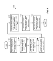
- FIG. 4 is a flowchart illustrating an example process 400 that can be executed in implementations of the present disclosure.
- a first operation using a first system is executed ( 402 ), the first operation generating first output data.
- the system 102 of FIG. 1 executes a first operation of a distributed process and provides corresponding output.
- a first fieldset is generated ( 404 ), the first fieldset being resident at the first system and including one or more fields corresponding to the first output data.
- the system 102 of FIG. 1 generates the fieldset.
- the one or more fields of the first fieldset are populated with values of the first output data ( 406 ) and the first output data is transmitted to a second system ( 408 ).
- the system 102 of FIG. 1 populates the one or more fields of the first fieldset with values of the first output data and the first output data is transmitted to the system 104 .
- a second operation is executed using the second system ( 410 ), the second operation generating second output data, the second output data overlapping the first output data.
- the system 104 executes the second operation of the distributed process and provides corresponding output.
- the second output data overlaps the first output data in the sense that data of the first output data corresponds to a field and data of the second output data corresponds to the field.
- a second fieldset is generated ( 412 ), the second fieldset being resident at the second system and including one or more fields corresponding to the first output data and the second output data.
- the second system 104 of FIG. 1 generates the second fieldset.
- the one or more fields of the second fieldset are populated with values of the second output data ( 414 ).
- the second system 104 of FIG. 1 populates the one or more fields of the first fieldset with values of the second output data.
- Implementations of the present disclosure provide mask sets for routing data between a plurality of systems (e.g., systems 102 , 104 , 106 ) within a network architecture (e.g. network 100 ).
- a mask set is similar to a fieldset, discussed above with reference to FIG. 2 .
- the fields of a mask set define fields that must be absent from a dataset supplying input to an operation.
- mask sets provide an expressive capability. For example, a system can specify that specifies that it does not want to receive data whose origin is itself.
- the system can register one or more mask sets with the IRL. When routing data between systems, the IRL can reference the registered one or more mask sets to determine whether particular data should be routed to a particular system.
- FIG. 5A is a diagram illustrating an update relationship between first and second systems.
- FIG. 5B is a diagram illustrating the update relationship between the first and second systems of FIG. 5A in the context of mask sets.
- a first system 500 generates an update fieldset 502 including an update 504 and an indicator 506 , the indicator indicating the first system 500 as the source of the update 504 .
- a second system 510 consumes the data provided in the update fieldset 502 .
- the second system 510 also generates an update fieldset 512 including an update 514 and an indicator 516 , the indicator indicating the second system 510 as the source of the update 514 .
- the first system 500 consumes the data provided in the update fieldset 512 .
- the first system 500 registers a mask set with the IRL.
- the mask set of the first system 500 can be identical to the fieldset 502 with the fields of the mask set indicating datasets that should not be routed to the first system.
- the mask set registered by the first system 500 can include a mask field including the value SYS — 1.
- the first system 500 can indicate that it does not want to receive datasets corresponding to updates that it generates itself. Consequently, when the first system 500 generates an update and broadcasts a corresponding update dataset for the consumption of other systems (e.g., the second system 510 ), the update dataset is not also routed back to the first system 500 , from which it originated.
- the second system 510 registers a mask set with the IRL.
- the mask set of the second system 510 can be identical to the fieldset 512 with the fields of the mask set indicating datasets that should not be routed to the first system.
- the mask set registered by the second system 510 can include a mask field including the value SYS — 2.
- the second system 510 can indicate that it does not want to receive datasets corresponding to updates that it generates itself. Consequently, when the second system 510 generates an update and broadcasts a corresponding update dataset for the consumption of other systems (e.g., the first system 500 ), the update dataset is not also routed back to the second system 510 , from which it originated.
- FIG. 6 is a flowchart illustrating an example process 600 that can be executed in implementations of the present disclosure.
- a mask set is registered ( 602 ), the mask set including one or more fields, each of the one or more fields indicating a field that must be absent from datasets that are to be provided as input to a first system of a plurality of systems.
- the IRL 108 of FIG. 1 can receive the mask set from the system 102 and can register the mask set for routing of one or more datasets within the network architecture 100 .
- a dataset is received ( 604 ), the dataset including a field that is present in the mask set.
- the IRL 108 of FIG. 1 can receive a dataset from one of systems 102 , 104 and 108 .
- the dataset is transmitted to one or more systems of the plurality of systems ( 606 ).
- the IRL 108 of FIG. 1 can transmit the dataset to one of systems 104 and 108 .
- the IRL 108 of FIG. 1 can inhibit transmission of the data set to the system 102 , the mask set indicating that the dataset should not be provided as input to the system 102 .
- Implementations of the present disclosure and all of the functional operations provided herein can be realized in digital electronic circuitry, or in computer software, firmware, or hardware, including the structures disclosed in this specification and their structural equivalents, or in combinations of one or more of them.
- Implementations of the invention can be realized as one or more computer program products, i.e., one or more modules of computer program instructions encoded on a computer readable medium for execution by, or to control the operation of, data processing apparatus.
- the computer readable medium can be a machine-readable storage device, a machine-readable storage substrate, a memory device, a composition of matter effecting a machine-readable propagated signal, or a combination of one or more of them.
- data processing apparatus encompasses all apparatus, devices, and machines for processing data, including by way of example a programmable processor, a computer, or multiple processors or computers.
- the apparatus can include, in addition to hardware, code that creates an execution environment for the computer program in question, e.g., code that constitutes processor firmware, a protocol stack, a database management system, an operating system, or a combination of one or more of them.
- a computer program (also known as a program, software, software application, script, or code) can be written in any form of programming language, including compiled or interpreted languages, and it can be deployed in any form, including as a stand alone program or as a module, component, subroutine, or other unit suitable for use in a computing environment.
- a computer program does not necessarily correspond to a file in a file system.
- a program can be stored in a portion of a file that holds other programs or data (e.g., one or more scripts stored in a markup language document), in a single file dedicated to the program in question, or in multiple coordinated files (e.g., files that store one or more modules, sub programs, or portions of code).
- a computer program can be deployed to be executed on one computer or on multiple computers that are located at one site or distributed across multiple sites and interconnected by a communication network.
- the processes and logic flows described in this disclose can be performed by one or more programmable processors executing one or more computer programs to perform functions by operating on input data and generating output.
- the processes and logic flows can also be performed by, and apparatus can also be implemented as, special purpose logic circuitry, e.g., an FPGA (field programmable gate array) or an ASIC (application specific integrated circuit).
- processors suitable for the execution of a computer program include, by way of example, both general and special purpose microprocessors, and any one or more processors of any kind of digital computer.
- a processor will receive instructions and data from a read only memory or a random access memory or both.
- the essential elements of a computer are a processor for performing instructions and one or more memory devices for storing instructions and data.
- a computer will also include, or be operatively coupled to receive data from or transfer data to, or both, one or more mass storage devices for storing data, e.g., magnetic, magneto optical disks, or optical disks.
- mass storage devices for storing data, e.g., magnetic, magneto optical disks, or optical disks.
- a computer need not have such devices.
- a computer can be embedded in another device, e.g., a mobile telephone, a personal digital assistant (PDA), a mobile audio player, a Global Positioning System (GPS) receiver, to name just a few.
- Computer readable media suitable for storing computer program instructions and data include all forms of non volatile memory, media and memory devices, including by way of example semiconductor memory devices, e.g., EPROM, EEPROM, and flash memory devices; magnetic disks, e.g., internal hard disks or removable disks; magneto optical disks; and CD ROM and DVD-ROM disks.
- the processor and the memory can be supplemented by, or incorporated in, special purpose logic circuitry.
- implementations of the invention can be implemented on a computer having a display device, e.g., a CRT (cathode ray tube) or LCD (liquid crystal display) monitor, for displaying information to the user and a keyboard and a pointing device, e.g., a mouse or a trackball, by which the user can provide input to the computer.
- a display device e.g., a CRT (cathode ray tube) or LCD (liquid crystal display) monitor
- keyboard and a pointing device e.g., a mouse or a trackball
- Other kinds of devices can be used to provide for interaction with a user as well; for example, feedback provided to the user can be any form of sensory feedback, e.g., visual feedback, auditory feedback, or tactile feedback; and input from the user can be received in any form, including acoustic, speech, or tactile input.
- Implementations of the present disclosure can be realized in a computing system that includes a back end component, e.g., as a data server, or that includes a middleware component, e.g., an application server, or that includes a front end component, e.g., a client computer having a graphical user interface or a Web browser through which a user can interact with an implementation of the present disclosure, or any combination of one or more such back end, middleware, or front end components.
- the components of the system can be interconnected by any form or medium of digital data communication, e.g., a communication network. Examples of communication networks include a local area network (“LAN”) and a wide area network (“WAN”), e.g., the Internet.
- LAN local area network
- WAN wide area network
- the computing system can include clients and servers.
- a client and server are generally remote from each other and typically interact through a communication network.
- the relationship of client and server arises by virtue of computer programs running on the respective computers and having a client-server relationship to each other.
- HTML file In each instance where an HTML file is mentioned, other file types or formats may be substituted. For instance, an HTML file may be replaced by an XML, JSON, plain text, or other types of files. Moreover, where a table or hash table is mentioned, other data structures (such as spreadsheets, relational databases, or structured files) may be used.
Abstract
Description
Claims (20)
Priority Applications (1)
| Application Number | Priority Date | Filing Date | Title |
|---|---|---|---|
| US13/284,675 US8825715B1 (en) | 2010-10-29 | 2011-10-28 | Distributed state/mask sets |
Applications Claiming Priority (2)
| Application Number | Priority Date | Filing Date | Title |
|---|---|---|---|
| US40836410P | 2010-10-29 | 2010-10-29 | |
| US13/284,675 US8825715B1 (en) | 2010-10-29 | 2011-10-28 | Distributed state/mask sets |
Publications (1)
| Publication Number | Publication Date |
|---|---|
| US8825715B1 true US8825715B1 (en) | 2014-09-02 |
Family
ID=51400132
Family Applications (1)
| Application Number | Title | Priority Date | Filing Date |
|---|---|---|---|
| US13/284,675 Expired - Fee Related US8825715B1 (en) | 2010-10-29 | 2011-10-28 | Distributed state/mask sets |
Country Status (1)
| Country | Link |
|---|---|
| US (1) | US8825715B1 (en) |
Cited By (1)
| Publication number | Priority date | Publication date | Assignee | Title |
|---|---|---|---|---|
| US20130282697A1 (en) * | 2012-04-18 | 2013-10-24 | International Business Machines Corporation | Data masking |
Citations (36)
| Publication number | Priority date | Publication date | Assignee | Title |
|---|---|---|---|---|
| US5652806A (en) * | 1992-01-10 | 1997-07-29 | Compaq Computer Corporation | Input device with data targeting to determine an entry field for a block of stroke data |
| WO1998043181A1 (en) * | 1997-03-21 | 1998-10-01 | Medical Talk Systems Limited | Form data entry with matching of the field type |
| US6049832A (en) * | 1996-11-15 | 2000-04-11 | Wall Data Incorporated | Method for accessing information on a host computer from a client computer through an intelligent virtual host component |
| US6216131B1 (en) * | 1998-02-06 | 2001-04-10 | Starfish Software, Inc. | Methods for mapping data fields from one data set to another in a data processing environment |
| US6282632B1 (en) * | 1997-08-29 | 2001-08-28 | Matsushita Electric Industrial Co., Ltd. | Information processor having duplicate operation flags |
| US20020073138A1 (en) * | 2000-12-08 | 2002-06-13 | Gilbert Eric S. | De-identification and linkage of data records |
| US20020194035A1 (en) * | 1996-03-28 | 2002-12-19 | Dirienzo Andrew L. | Attachment integrated claims system and operating method therefor |
| US6538660B1 (en) * | 1999-11-12 | 2003-03-25 | International Business Machines Corporation | Method, system, and program for superimposing data from different application programs |
| US6732088B1 (en) * | 1999-12-14 | 2004-05-04 | Xerox Corporation | Collaborative searching by query induction |
| US20040122869A1 (en) * | 2002-12-23 | 2004-06-24 | Gordon Muehl | Conflict detection in a distributed system landscape |
| US20050086381A1 (en) * | 2001-12-21 | 2005-04-21 | Flinders Aps | Method of transferring data between different types of computer systems |
| US20050086199A1 (en) * | 1998-03-31 | 2005-04-21 | Champagne Darryl G. | Transferring records between two databases |
| US20050193142A1 (en) | 2002-02-08 | 2005-09-01 | Thwaites Jacoby M. | Information routing |
| US20050222981A1 (en) * | 2004-03-31 | 2005-10-06 | Lawrence Stephen R | Systems and methods for weighting a search query result |
| US20050246390A1 (en) * | 2001-08-24 | 2005-11-03 | House Richard W | Enterprise test data management system utilizing automatically created test data structures and related methods |
| US20050278492A1 (en) * | 2004-06-10 | 2005-12-15 | Stakutis Christopher J | Method, system, and program for migrating source data to target data |
| US20050289100A1 (en) * | 2004-06-25 | 2005-12-29 | International Business Machines Corporation | Techniques for representing relationships between queries |
| US20060056626A1 (en) * | 2004-09-16 | 2006-03-16 | International Business Machines Corporation | Method and system for selectively masking the display of data field values |
| US20060074897A1 (en) * | 2004-10-04 | 2006-04-06 | Fergusson Iain W | System and method for dynamic data masking |
| US20060085399A1 (en) * | 2004-10-19 | 2006-04-20 | International Business Machines Corporation | Prediction of query difficulty for a generic search engine |
| US7133913B2 (en) | 2000-08-09 | 2006-11-07 | Thwaites Jacoby M | Information routing |
| US20070016824A1 (en) * | 2005-07-14 | 2007-01-18 | International Business Machines Corporation | Methods and apparatus for global systems management |
| US20070027855A1 (en) * | 2005-07-27 | 2007-02-01 | Sony Corporation | Information processing apparatus, information processing method, and program |
| US20070043693A1 (en) * | 2005-08-18 | 2007-02-22 | Jan Krieg | Systems and methods for storing a dataset having a hierarchical data structure in a database |
| US20070110224A1 (en) * | 2005-11-14 | 2007-05-17 | Accenture Global Services Gmbh | Data masking application |
| US20080033934A1 (en) * | 2006-08-07 | 2008-02-07 | Bea Systems, Inc. | Distributed query search |
| US20080065665A1 (en) * | 2006-09-08 | 2008-03-13 | Plato Group Inc. | Data masking system and method |
| US20080222141A1 (en) * | 2007-03-07 | 2008-09-11 | Altep, Inc. | Method and System for Document Searching |
| US20080319942A1 (en) * | 2007-05-14 | 2008-12-25 | Samir Courdy | Method and system for report generation including extensible data |
| US20090013279A1 (en) * | 2007-07-03 | 2009-01-08 | Apple Inc. | Form-field mask for sensitive data |
| US20090281974A1 (en) * | 2008-04-08 | 2009-11-12 | Infosys Technologies Limited | System and method for adaptive data masking |
| US20090287678A1 (en) * | 2008-05-14 | 2009-11-19 | International Business Machines Corporation | System and method for providing answers to questions |
| US20100088590A1 (en) * | 2008-10-07 | 2010-04-08 | Bigmachines, Inc. | Methods and apparatus for generating a dynamic document |
| US20100135535A1 (en) * | 2006-02-28 | 2010-06-03 | Cocreate Software Gmbh | Method for Comparing First Computer-Aided 3D Model with a Second Computer-Aided 3D Model |
| US20100146070A1 (en) * | 2006-12-21 | 2010-06-10 | Nokia Corporation | Filtering transferred data |
| US20110055231A1 (en) * | 2009-08-27 | 2011-03-03 | Huck Bridget K | Multi-database query system and method |
-
2011
- 2011-10-28 US US13/284,675 patent/US8825715B1/en not_active Expired - Fee Related
Patent Citations (36)
| Publication number | Priority date | Publication date | Assignee | Title |
|---|---|---|---|---|
| US5652806A (en) * | 1992-01-10 | 1997-07-29 | Compaq Computer Corporation | Input device with data targeting to determine an entry field for a block of stroke data |
| US20020194035A1 (en) * | 1996-03-28 | 2002-12-19 | Dirienzo Andrew L. | Attachment integrated claims system and operating method therefor |
| US6049832A (en) * | 1996-11-15 | 2000-04-11 | Wall Data Incorporated | Method for accessing information on a host computer from a client computer through an intelligent virtual host component |
| WO1998043181A1 (en) * | 1997-03-21 | 1998-10-01 | Medical Talk Systems Limited | Form data entry with matching of the field type |
| US6282632B1 (en) * | 1997-08-29 | 2001-08-28 | Matsushita Electric Industrial Co., Ltd. | Information processor having duplicate operation flags |
| US6216131B1 (en) * | 1998-02-06 | 2001-04-10 | Starfish Software, Inc. | Methods for mapping data fields from one data set to another in a data processing environment |
| US20050086199A1 (en) * | 1998-03-31 | 2005-04-21 | Champagne Darryl G. | Transferring records between two databases |
| US6538660B1 (en) * | 1999-11-12 | 2003-03-25 | International Business Machines Corporation | Method, system, and program for superimposing data from different application programs |
| US6732088B1 (en) * | 1999-12-14 | 2004-05-04 | Xerox Corporation | Collaborative searching by query induction |
| US7133913B2 (en) | 2000-08-09 | 2006-11-07 | Thwaites Jacoby M | Information routing |
| US20020073138A1 (en) * | 2000-12-08 | 2002-06-13 | Gilbert Eric S. | De-identification and linkage of data records |
| US20050246390A1 (en) * | 2001-08-24 | 2005-11-03 | House Richard W | Enterprise test data management system utilizing automatically created test data structures and related methods |
| US20050086381A1 (en) * | 2001-12-21 | 2005-04-21 | Flinders Aps | Method of transferring data between different types of computer systems |
| US20050193142A1 (en) | 2002-02-08 | 2005-09-01 | Thwaites Jacoby M. | Information routing |
| US20040122869A1 (en) * | 2002-12-23 | 2004-06-24 | Gordon Muehl | Conflict detection in a distributed system landscape |
| US20050222981A1 (en) * | 2004-03-31 | 2005-10-06 | Lawrence Stephen R | Systems and methods for weighting a search query result |
| US20050278492A1 (en) * | 2004-06-10 | 2005-12-15 | Stakutis Christopher J | Method, system, and program for migrating source data to target data |
| US20050289100A1 (en) * | 2004-06-25 | 2005-12-29 | International Business Machines Corporation | Techniques for representing relationships between queries |
| US20060056626A1 (en) * | 2004-09-16 | 2006-03-16 | International Business Machines Corporation | Method and system for selectively masking the display of data field values |
| US20060074897A1 (en) * | 2004-10-04 | 2006-04-06 | Fergusson Iain W | System and method for dynamic data masking |
| US20060085399A1 (en) * | 2004-10-19 | 2006-04-20 | International Business Machines Corporation | Prediction of query difficulty for a generic search engine |
| US20070016824A1 (en) * | 2005-07-14 | 2007-01-18 | International Business Machines Corporation | Methods and apparatus for global systems management |
| US20070027855A1 (en) * | 2005-07-27 | 2007-02-01 | Sony Corporation | Information processing apparatus, information processing method, and program |
| US20070043693A1 (en) * | 2005-08-18 | 2007-02-22 | Jan Krieg | Systems and methods for storing a dataset having a hierarchical data structure in a database |
| US20070110224A1 (en) * | 2005-11-14 | 2007-05-17 | Accenture Global Services Gmbh | Data masking application |
| US20100135535A1 (en) * | 2006-02-28 | 2010-06-03 | Cocreate Software Gmbh | Method for Comparing First Computer-Aided 3D Model with a Second Computer-Aided 3D Model |
| US20080033934A1 (en) * | 2006-08-07 | 2008-02-07 | Bea Systems, Inc. | Distributed query search |
| US20080065665A1 (en) * | 2006-09-08 | 2008-03-13 | Plato Group Inc. | Data masking system and method |
| US20100146070A1 (en) * | 2006-12-21 | 2010-06-10 | Nokia Corporation | Filtering transferred data |
| US20080222141A1 (en) * | 2007-03-07 | 2008-09-11 | Altep, Inc. | Method and System for Document Searching |
| US20080319942A1 (en) * | 2007-05-14 | 2008-12-25 | Samir Courdy | Method and system for report generation including extensible data |
| US20090013279A1 (en) * | 2007-07-03 | 2009-01-08 | Apple Inc. | Form-field mask for sensitive data |
| US20090281974A1 (en) * | 2008-04-08 | 2009-11-12 | Infosys Technologies Limited | System and method for adaptive data masking |
| US20090287678A1 (en) * | 2008-05-14 | 2009-11-19 | International Business Machines Corporation | System and method for providing answers to questions |
| US20100088590A1 (en) * | 2008-10-07 | 2010-04-08 | Bigmachines, Inc. | Methods and apparatus for generating a dynamic document |
| US20110055231A1 (en) * | 2009-08-27 | 2011-03-03 | Huck Bridget K | Multi-database query system and method |
Cited By (2)
| Publication number | Priority date | Publication date | Assignee | Title |
|---|---|---|---|---|
| US20130282697A1 (en) * | 2012-04-18 | 2013-10-24 | International Business Machines Corporation | Data masking |
| US9135315B2 (en) * | 2012-04-18 | 2015-09-15 | Internatonal Business Machines Corporation | Data masking |
Similar Documents
| Publication | Publication Date | Title |
|---|---|---|
| US9740591B2 (en) | Aggregating source code metric values | |
| US9477787B2 (en) | Method and apparatus for information clustering based on predictive social graphs | |
| CN107122431A (en) | A kind of real-time calculating platform and the method for computing data based on real-time calculating platform | |
| US10193882B2 (en) | Provision of cross-device identification | |
| WO2015104457A1 (en) | Method and apparatus for determining partial updates for a document object model | |
| US10091336B2 (en) | Computing platform agnostic application server | |
| US9092499B2 (en) | Synchronizing endpoint data stores having disparate schemas | |
| US11567918B2 (en) | Generating context tree data based on a tailored data model | |
| US20120166464A1 (en) | Method and apparatus for providing input suggestions | |
| US11947595B2 (en) | Storing semi-structured data | |
| US8650280B2 (en) | Monitoring distributed task execution using a chained text messaging system | |
| US20110061064A1 (en) | Integrating enterprise repository events into business process model and notation processes | |
| US20130346600A1 (en) | Apparatus for processing one or more events | |
| CN114401187B (en) | Gray scale issuing method, device, computer equipment and storage medium | |
| US20120221861A1 (en) | Method and apparatus for providing end-to-end security for distributed computations | |
| US20110055200A1 (en) | Method and apparatus for utilizing existing hash identifiers of decision diagrams | |
| US8825715B1 (en) | Distributed state/mask sets | |
| US8949664B2 (en) | Method and apparatus for providing information consistency in distributed computing environments | |
| US10067808B2 (en) | Nondeterministic operation execution environment utilizing resource registry | |
| US20120137044A1 (en) | Method and apparatus for providing persistent computations | |
| US20110055221A1 (en) | Method and apparatus for obtaining decision diagrams from unknown hash identifiers | |
| US10621627B2 (en) | Running client experiments based on server-side user segment data | |
| WO2022132617A1 (en) | Using secure multi-party computation and probabilistic data structures to protect access to information | |
| CN108809687B (en) | System and method for providing cross-network event attribution | |
| US8799318B2 (en) | Function module leveraging fuzzy search capability |
Legal Events
| Date | Code | Title | Description |
|---|---|---|---|
| AS | Assignment |
Owner name: GOOGLE INC., CALIFORNIA Free format text: ASSIGNMENT OF ASSIGNORS INTEREST;ASSIGNOR:THWAITES, JACOBY;REEL/FRAME:027399/0791 Effective date: 20101118 |
|
| STCF | Information on status: patent grant |
Free format text: PATENTED CASE |
|
| AS | Assignment |
Owner name: GOOGLE LLC, CALIFORNIA Free format text: CHANGE OF NAME;ASSIGNOR:GOOGLE INC.;REEL/FRAME:044277/0001 Effective date: 20170929 |
|
| MAFP | Maintenance fee payment |
Free format text: PAYMENT OF MAINTENANCE FEE, 4TH YEAR, LARGE ENTITY (ORIGINAL EVENT CODE: M1551) Year of fee payment: 4 |
|
| FEPP | Fee payment procedure |
Free format text: MAINTENANCE FEE REMINDER MAILED (ORIGINAL EVENT CODE: REM.); ENTITY STATUS OF PATENT OWNER: LARGE ENTITY |
|
| LAPS | Lapse for failure to pay maintenance fees |
Free format text: PATENT EXPIRED FOR FAILURE TO PAY MAINTENANCE FEES (ORIGINAL EVENT CODE: EXP.); ENTITY STATUS OF PATENT OWNER: LARGE ENTITY |
|
| STCH | Information on status: patent discontinuation |
Free format text: PATENT EXPIRED DUE TO NONPAYMENT OF MAINTENANCE FEES UNDER 37 CFR 1.362 |
|
| FP | Lapsed due to failure to pay maintenance fee |
Effective date: 20220902 |