US8820429B2 - Fertilizer applicator with in-frame folding actuator for folding an outer frame member relative to an inner frame member - Google Patents
Fertilizer applicator with in-frame folding actuator for folding an outer frame member relative to an inner frame member Download PDFInfo
- Publication number
- US8820429B2 US8820429B2 US13/075,850 US201113075850A US8820429B2 US 8820429 B2 US8820429 B2 US 8820429B2 US 201113075850 A US201113075850 A US 201113075850A US 8820429 B2 US8820429 B2 US 8820429B2
- Authority
- US
- United States
- Prior art keywords
- wing
- frame
- frame member
- actuator
- fertilizer applicator
- Prior art date
- Legal status (The legal status is an assumption and is not a legal conclusion. Google has not performed a legal analysis and makes no representation as to the accuracy of the status listed.)
- Active, expires
Links
Images


Classifications
-
- A—HUMAN NECESSITIES
- A01—AGRICULTURE; FORESTRY; ANIMAL HUSBANDRY; HUNTING; TRAPPING; FISHING
- A01B—SOIL WORKING IN AGRICULTURE OR FORESTRY; PARTS, DETAILS, OR ACCESSORIES OF AGRICULTURAL MACHINES OR IMPLEMENTS, IN GENERAL
- A01B73/00—Means or arrangements to facilitate transportation of agricultural machines or implements, e.g. folding frames to reduce overall width
- A01B73/02—Folding frames
- A01B73/04—Folding frames foldable about a horizontal axis
- A01B73/044—Folding frames foldable about a horizontal axis the axis being oriented in a longitudinal direction
- A01B73/046—Folding frames foldable about a horizontal axis the axis being oriented in a longitudinal direction each folding frame part being foldable in itself
-
- A—HUMAN NECESSITIES
- A01—AGRICULTURE; FORESTRY; ANIMAL HUSBANDRY; HUNTING; TRAPPING; FISHING
- A01C—PLANTING; SOWING; FERTILISING
- A01C23/00—Distributing devices specially adapted for liquid manure or other fertilising liquid, including ammonia, e.g. transport tanks or sprinkling wagons
- A01C23/02—Special arrangements for delivering the liquid directly into the soil
- A01C23/023—Special arrangements for delivering the liquid directly into the soil for liquid or gas fertilisers
Definitions
- the present invention relates to farm implements and, more particularly, to a foldable fertilizer applicator.
- Fertilizer applicators are used to apply liquid-gaseous fertilizer, such as anhydrous ammonia, to a farm field.
- a conventional fertilizer applicator will consist of a carrier frame and left and right wing booms mounted to opposite sides of the carrier frame. Pivoting mechanisms are used to fold the left and right wing booms vertically, i.e., along a fore-aft dimension of the carrier frame, from an extended working position to a folded, transport position.
- fertilizer applicators In an effort to increase the operational width of fertilizer applicators and thereby reduce the time required to apply the liquid-gaseous fertilizer to acreage, fertilizer applicators have been designed with the left and right wing booms, with each having an inner frame section that is pivotally mounted to the carrier frame and an outer frame section that is pivotally mounted to the inner frame section.
- a typical fertilizer applicator having double fold wings will have a working width between twenty-seven and fifty-two feet, and a transport width of less than twenty feet, e.g., approximately seventeen feet.
- the present invention is directed to a fertilizer applicator of increased operating width, e.g., sixty (60) or sixty-five (65) feet, having a carrier frame and a pair of wing sections pivotally mounted to opposite ends of the carrier frame.
- the wing sections include an inner wing member and an outer wing member.
- Each wing section includes an actuator for folding/unfolding a respective outer wing member relative to a respective inner wing member.
- the inner wing member includes a frame member defining an elongated cavity, and the actuator is positioned within the elongated cavity.
- the actuator can effectively fold/unfold the outer wing member relative to the inner wing member without the physical structure of the actuator impeding movement of the outer wing member. This allows the outer wing member to pivot upland to a position against the inner wing member.
- a fertilizer applicator including a frame assembly having a carrier frame and a pair of outer wings pivotally coupled to opposite lateral ends of the carrier frame.
- the carrier frame is adapted to be coupled to a towing vehicle and the outer wings each have an inner wing portion and an outer wing portion pivotally coupled to the inner wing portion.
- the inner wing portion includes an inner wing frame member and the outer wing portion includes an outer wing frame member pivotally coupled to the inner wing frame member, and each inner wing frame member includes an elongated hollow portion formed along a length of the inner wing frame member.
- the fertilizer applicator further includes an actuator assembly having a pair of actuators for folding/unfolding the outer wing members relative to the inner wing members.
- An actuator is located in each one of the hollow portions of the inner wing frame members, with each actuator having a first end coupled to an inner wing frame member and a second end, opposite the first end, that is coupled to an outer wing frame member and wherein operation of each actuator causes an associated outer wing members to pivot about a pivot connection with an associated inner wing member.
- the fertilizer applicator further includes a plurality of ground engaging tools mounted to the frame assembly.
- a farm implement comprises a frame assembly including a carrier frame and a pair of wing frame assemblies mounted to the carrier frame, with each wing frame assembly including first, second, and third outer wing members with the first wing member pivotally coupled to the carrier frame, the second wing member pivotally coupled to the first wing member, and the third wing member pivotally coupled to the second wing member.
- the farm implement further comprises first and second hydraulic actuators, wherein the first hydraulic actuator is interconnected between the carrier frame and first wing members of a first wing frame assembly and wherein the second hydraulic actuator is interconnected between the first and second wing members of a second wing frame assembly, and wherein each second wing member provides a housing for a respective one of a third hydraulic actuator.
- a fertilizer system includes a tractor and a fertilizer applicator hitched to the tractor.
- the fertilizer applicator has a seven-section frame assembly with a width of at least sixty feet.
- the seven-section frame assembly includes a carrier frame coupled to the tractor and configured to support first and second outer wing sections in a folded position in which the first and second outer wing sections are located above the carrier frame, and wherein the carrier frame includes an actuator arrangement for folding and unfolding the first and second outer wing sections.
- the first and second outer wing sections each include an inner frame member, a middle frame member, and an outer frame member, with the outer frame member pivotally coupled to the middle frame member and configured to pivot upland, i.e., toward the tractor or towing vehicle, about a vertical axis by an actuator when the outer frame member is being pivoted from an extended working position to a folded transport position and wherein the actuator is positioned within an elongated cavity defined by the middle frame member.
- the fertilizer system further includes a plurality of soil engaging tools mounted to the carrier frame and the first and second outer wing sections.
- One aspect of the invention is a foldable fertilizer applicator having a working width of at least sixty feet.
- Another aspect of the invention is a fertilizer applicator having a reduced transport height dimension.
- Yet a further aspect of the invention is a fertilizer applicator having a front-folding outer wing frame member and an in-frame actuator to fold/unfold the outer wing frame member.
- FIG. 1 is a pictorial view of a fertilizing system having a fertilizer applicator incorporating the principles of the present invention
- FIG. 2 is an isometric view of a fertilizer applicator according to one embodiment of the invention.
- FIG. 2A-2C are isometric views of fertilizer applicators according to other embodiments of the invention.
- FIG. 3 is an isometric view of a portion of the frame assembly of the fertilizer applicator of FIG. 2 , with an outer wing portion of the frame assembly in an unfolded, working position;
- FIG. 4 is a top plan view of the frame assembly shown in FIG. 3 ;
- FIG. 5 is an isometric view of the portion of the frame assembly of the fertilizer applicator shown in FIG. 3 , with the outer wing portion of the frame assembly in a folded position;
- FIG. 6 is top plan view of the frame assembly shown in FIG. 5 ;
- FIG. 7 is a section view of the frame assembly taken along line 7 - 7 of FIG. 3 ;
- FIG. 8 is a section view of the frame assembly taken along line 8 - 8 of FIG. 3 ;
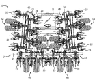
- FIG. 9 is a rear elevation view of the fertilizer applicator of FIG. 2 in a folded transport position.
- FIG. 1 shows a fertilizing system 10 having a tractor 12 and a fertilizer applicator 14 coupled to the tractor 12 in a conventional manner so as to be pulled by the tractor 12 along a farm field or roadway. While a tractor 12 is shown, it is understood that other types of towing vehicles could be used to tow the fertilizer applicator.
- a fertilizer tank 15 is supported by a wheeled cart 17 , which is removably coupled to rearward portion of the fertilizer applicator 14 , and supplies gaseous fertilizer to the fertilizer applicator 14 for deposition onto ground in a known manner.
- the fertilizer may be of any known type, such as liquid, gas, or flowable granular.
- the fertilizer applicator 14 has a frame assembly 16 to which ground engaging tools 18 are mounted.
- the ground engaging tools 18 include shanks 20 mounted to the frame assembly with fifteen inch row spacing.
- FIG. 2A shows a fertilizer applicator according to another embodiment of the invention.
- the frame assembly 16 is smaller in operational width than the frame assembly shown in FIG. 2 and also has shanks 20 mounted to the frame assembly with fifteen inch row spacing.
- FIG. 2B shows a fertilizer applicator with a frame assembly similar to the frame assembly illustrated in FIG. 2 but with disc coulters 21 in addition to shanks 20 mounted to the frame assembly.
- the shanks 20 and coulters 21 are mounted with thirty inch row spacing.
- FIG. 2C shows another fertilizer applicator according to the invention.
- the frame assembly is similar to that shown in FIG. 2A , but has shanks 20 , coulters 21 , and sealing discs 23 mounted to the frame assembly.
- different types of ground engaging tools may be mounted to the frame assembly 16 and that the invention is not limited to any particular arrangement.
- the operational widths of the frame assemblies may be different that explicitly described and the spacing between ground engaging tools may be different from that described.
- the frame assembly has an operational width of sixty feet or sixty-five feet, but the invention is not so limited.
- the frame assembly 16 also includes a tongue 22 having a receiver 24 at its forward end for coupling the frame assembly 16 to the tractor 12 .
- the receiver 24 may take one of many forms for hitching the frame assembly 16 to the tractor 12 .
- the receiver 24 may fit over a ball (not shown) mounted to a rear portion of the chassis of the tractor 12 .
- the frame assembly 16 further supports various hoses and hydraulic connections to support the transfer of fertilizer from the tank 15 .
- the structural features are generally well-known in the art and thus will not be described further herein.
- the fertilizer applicator 14 includes means for lowering the frame assembly 16 into a ground engagement position and means for raising the frame assembly 16 from the ground engagement position.
- lifting/lowering means are well-known in the art and thus will not be described further herein. It is further understood that the invention is not limited to any particular lifting/raising means or any particular systems for transferring fertilizer from the tank 15 to nozzles (not shown) mounted to the frame assembly 16 .
- the frame assembly 16 consists of a center frame section, or carrier frame 26 , and a pair of wing sections or “booms” 28 , 30 that flank opposite sides of the carrier frame 26 .
- Wing section 28 is mounted to the left side of the carrier frame 26 and wing section 30 is mounted to the right side of the carrier frame (as viewed from a rear of the fertilizer applicator 14 toward the tractor 12 ).
- Wing sections 28 and 30 are similarly constructed and, as such, for purposes of description, only wing section 28 will be described further herein, but it is understood that the description of wing section 28 also applies to wing section 30 .
- Wing section 28 has an inner wing portion 32 , a middle wing portion 34 , and an outer wing portion 36 .
- the inner wing portion 32 has a forward frame member 38 , an intermediate frame member 40 , and a rearward frame member 42 .
- Frame members 38 , 40 , and 42 are arranged parallel to one another and are transverse to a longitudinal axis 46 of the fertilizer applicator 12 .
- End frame members 48 and 50 connect the forward, intermediate, and rearward frame members 38 , 40 , and 42 , respectively, into an integrated unit.
- the forward frame member 38 and the rearward frame member 42 are each pivotally coupled to the carrier frame 26 at joints 52 and 54 , respectively.
- the carrier frame 26 has a forward frame member 56 and a rearward frame member 58 that align with frame members 38 and 42 , respectively.
- An end of forward frame member 38 and an end of the forward frame member 56 are each pinned to a forward linking member 60 and an end of the rearward frame member 42 and an end of the rearward frame member 58 are each pinned to a rearward linking member 62 .
- These pinned connections with the linking members 60 , 62 enable the inner wing portion 32 to be rotated upward along a folding axis 64 , which is parallel to longitudinal axis 46 .
- the carrier frame 26 which is supported above the ground by a pair of tandem wheels 66 , includes a pair of up-folding actuators 68 , each of which folds a respective inner wing portion 32 , and, as will be explained, the middle wing portion 34 and the outer wing portion 36 to a transport position above the carrier frame 26 .
- the middle wing portion 34 is similar in construction to the inner wing portion 32 in having a forward frame member 70 , an intermediate frame member 72 , a rearward frame member 74 , and a pair of connecting frame members 76 and 78 .
- the middle wing portion 34 connects to the inner wing portion 32 via a pair of linking members 80 and 82 .
- the connection of the inner wing portion 32 and the middle wing portion 34 allows the middle wing portion 34 to be folded over the inner wing portion 32 via actuator 84 .
- the actuator 84 includes a barrel 86 coupled to inner wing portion 32 , e.g., forward frame member 38 , and a rod 88 connected to the middle wing portion 34 .
- the rod 88 connects to a bracket 90 coupled to the forward frame member 70 of the middle wing portion 34 .
- the middle wing portion 34 is unfolded such that the forward frame member 70 is co-aligned with forward frame member 38 of the inner wing portion 32 .
- the weight of the middle wing portion 34 and the outer wing portion 36 has been redistributed so as to load tandem support wheels 92 , 94 and outer wheel 95 .
- the inner wing portion is also supported by tandem wheels 94 when moved to the lowered (unfolded) position.
- the middle wing portion 34 (and the outer wing portion 36 as will be described) is folded vertically about longitudinal axis 96 , which is parallel to axes 46 and 64 .
- the outer wing portion 36 is somewhat similar to the construction of the inner and middle frame portions 32 , 34 .
- the outer wing portion 36 has a forward frame member 98 , a rearward frame member 100 , and connecting frame members 102 and 104 .
- the outer wing portion preferably does not have an intermediate frame member.
- the rearward frame member 100 preferably aligns with the intermediate frame member 72 of middle wing portion 34 .
- the forward frame member 98 of the outer wing portion 36 is pivotally coupled to the forward frame member 70 of the middle wing portion 34 via a pivot arrangement 106 .
- the pivot arrangement 106 enables the outer wing portion 36 to be folded upland or forward (in the direction of arrow 108 ) about vertical axis 110 approximately 180 degrees.
- the outer wing portion 36 is moved forward of a portion of the middle wing portion 34 so that the forward frame member 98 is adjacent the forward frame member 70 of the middle frame portion 34 , as shown in FIGS. 5 and 6 .
- the pivot arrangement 106 is the only connection of the outer wing portion 36 with the middle wing portion 34 .
- the connection of frame members 100 and 102 create a corner (not shown) that is received by a pocket (not numbered) formed by a pair of plates 110 and 112 mounted at the corner of frame members 72 and 78 .
- the space or gap (not numbered) formed between the plates 110 , 112 is slightly greater than the thickness of the frame members 100 and 102 to allow the shared corner of those members to be slidably received in the pocket formed by the plates 110 , 112 .
- the pivot arrangement 106 includes a pair of mounting plates 114 and 116 mounted to upper and lower surfaces of the forward frame member 98 .
- Each mounting plate 114 , 116 has an eyelet (not numbered) that are aligned with one another to receive a pivot pin 118 extending through an upright mounting sleeve 120 .
- the pivot pin 118 includes transverse holes (not numbered) at its upper and lower ends to enable cotter pins or similar fastening devices to secure the pin 118 in sleeve 120 and to prevent the mounting plates 114 , 116 from sliding out engagement with the pin and sleeve.
- forward frame member 70 is an elongated generally tubular member defining an elongated cavity 122 along the entire length of the forward frame member 70 .
- the elongated cavity 122 is sized to house an actuator 124 for pivoting the outer wing portion 36 about pin 118 as described above.
- Tie rods 126 hold the barrel or cylinder 128 together in a known manner. Alternately, a welded cylinder could be used.
- the actuator 124 further has a ram 130 that is connected to the outer wing portion 36 via a linkage assembly 132 .
- the linkage assembly 132 consists of a roller 134 that is connected on one side to the ram 130 and connected to an arm 136 on the opposite side.
- the arm 136 is connected to a bracket 138 that is secured to the forward frame member 98 of the outer wing portion 36 .
- the arm 136 is connected to the bracket 138 via an upright pivot pin 140 that allows the bracket 138 to swing the outer wing portion 36 around the pivot pin 118 when the ram 130 is being extended/retracted. Accordingly, when the ram 130 is extended, the roller 134 will push laterally outward against bracket 138 thereby causing the bracket to apply a pushing force against the forward frame member 98 .
- the pivot arrangement 106 transfers this linear motion of the ram 130 into rotational movement of the forward frame member 98 around pivot pin 118 until the ram 130 is fully extended and the outer wing portion 36 has reached its folded position, as shown in FIGS. 5 and 6 .
- Retraction of the ram 130 causes a reversal of the aforedescribed motion to unfold the outer wing portion 36 .
- the placement of the actuator 124 within the frame cavity and behind the forward frame member 70 positions the actuator within the footprint of the forward frame member 70 and thus clear from hindering the outer wing portion from folding generally tight against the middle wing portion. Moreover, since the actuator 124 is in the forward frame member 70 rather than extending laterally outward from the forward frame member 70 , the separation between the outer wing portion and the middle wing portion is relatively small. As a result, the fore-aft length of the frame assembly when folded is reduced.
- receiver 142 is mounted to a front side of the forward frame member 70 .
- the receiver 142 is secured to the forward frame member 70 by a mounting bracket 144 , which in the illustrated embodiment, is a clamp-type bracket having a pair of plates 146 , 148 held against the forward frame member 70 by bolts 150 .
- the receiver 142 is designed to help hold the outer wing portion 36 in place when in the folded position, as shown in FIGS. 5 and 6 , and thereby prevent swaying of the outer wing portion 36 when the fertilizer applicator 14 is being moved to, or is in, the folded position.
- FIG. 9 shows the fertilizer applicator 14 in the folded position.
- the outer wing portions are folded forward as described above to be adjacent a front side of the middle wing portions.
- the middle wing portions are then folded over the inner wing portions to provide a pre-transport stacked arrangement of the wing booms.
- the inner wing portions are folded vertically so that the inner wing portions are generally perpendicular to the ground.
- the wing booms are carried above the carrier frame 26 and the weight of the folded wing booms is supported by the carrier frame 26 and the transport tandem wheels 66 .
- the fertilizer applicator has a width of less than twenty feet, e.g., 18 feet, 9 inches.
- This transport width meets the demands for in-field movement, passing through gates or storage/barn doors, and for being towed along roadways. Moreover, the fertilizer applicator 14 is capable of meeting this transport parameter despite having a working width greater than fifty feet, e.g., sixty feet or sixty-five feet.
- the fertilizer applicator has an operational width of sixty feet, a transport height of approximately fourteen feet, and a transport width of approximately nineteen feet.
- the fertilizer applicator further has four walking tandem transport wheels and eight walking tandem wheels that support together with the transport wheels support the fertilizer applicator when in the working position.
- the fertilizer applicator further has a gross weight of 22,500 pounds and an operating speed between five to eight miles per hour.
- the fertilizer applicator has an operation width of sixty-five feet and a gross weight of 23,000 pounds.
- the working speed, transport width, transport height, and tandem wheels similar to that described above with respect to the sixty foot fertilizer applicator.
- the present invention has been described with respect to a fertilizer applicator but it is understood that the invention may be incorporated with other types of farm implements, including, for example, planters, seeders, drills, and the like. Moreover, the invention may be incorporated with farm implements that are towed by a tractor, such as that described herein, as well as implements that are mounted to a vehicle frame, such as a Case New Holland Titan Series floater and a Case New Holland Patriot Series sprayer.
Abstract
Description
Claims (19)
Priority Applications (2)
| Application Number | Priority Date | Filing Date | Title |
|---|---|---|---|
| US13/075,850 US8820429B2 (en) | 2011-03-30 | 2011-03-30 | Fertilizer applicator with in-frame folding actuator for folding an outer frame member relative to an inner frame member |
| CA2754381A CA2754381C (en) | 2011-03-30 | 2011-10-07 | Fertilizer applicator with in-frame folding actuator for folding an outer frame member relative to an inner frame member |
Applications Claiming Priority (1)
| Application Number | Priority Date | Filing Date | Title |
|---|---|---|---|
| US13/075,850 US8820429B2 (en) | 2011-03-30 | 2011-03-30 | Fertilizer applicator with in-frame folding actuator for folding an outer frame member relative to an inner frame member |
Publications (2)
| Publication Number | Publication Date |
|---|---|
| US20120247378A1 US20120247378A1 (en) | 2012-10-04 |
| US8820429B2 true US8820429B2 (en) | 2014-09-02 |
Family
ID=46925551
Family Applications (1)
| Application Number | Title | Priority Date | Filing Date |
|---|---|---|---|
| US13/075,850 Active 2032-11-25 US8820429B2 (en) | 2011-03-30 | 2011-03-30 | Fertilizer applicator with in-frame folding actuator for folding an outer frame member relative to an inner frame member |
Country Status (2)
| Country | Link |
|---|---|
| US (1) | US8820429B2 (en) |
| CA (1) | CA2754381C (en) |
Cited By (6)
| Publication number | Priority date | Publication date | Assignee | Title |
|---|---|---|---|---|
| US20150129253A1 (en) * | 2013-11-13 | 2015-05-14 | Cnh Industrial America Llc | Folding agricultural implement hinge system |
| US20150181797A1 (en) * | 2013-12-31 | 2015-07-02 | Daniel L. Abbott | Agricultural discing apparatus having bifold wing sections and method for forming same |
| US9968026B2 (en) * | 2016-10-10 | 2018-05-15 | Cnh Industrial America Llc | Apparatus and method for an agricultural implement folding frame |
| US10412876B2 (en) * | 2013-12-11 | 2019-09-17 | Cnh Industrial America Llc | Flexible wing sections for a field cultivator |
| US10798865B2 (en) | 2016-01-19 | 2020-10-13 | Fast Global Solutions Inc. | Agricultural implement with lift assist and uplift capability |
| US11477977B2 (en) | 2020-01-07 | 2022-10-25 | Cnh Industrial America Llc | Foldable rear boom section |
Families Citing this family (12)
| Publication number | Priority date | Publication date | Assignee | Title |
|---|---|---|---|---|
| US20140060867A1 (en) * | 2012-09-06 | 2014-03-06 | Cnh America Llc | Tool bar extension for an agricultural implement |
| US9596800B2 (en) * | 2013-11-13 | 2017-03-21 | Cnh Industrial America Llc | Triple-fold agricultural implement with narrow and low transport profile |
| US9521800B2 (en) * | 2013-11-13 | 2016-12-20 | Cnh Industrial America Llc | Triple-fold tillage implement with transport ready frontal profile |
| DE202016000649U1 (en) * | 2016-02-02 | 2017-05-03 | Alois Pöttinger Maschinenfabrik Ges.m.b.H. | Agricultural implement with folding machine frame |
| BR112018070762B1 (en) | 2016-04-18 | 2023-03-07 | Precision Planting Llc | FLUID APPLICATOR AND APPLICATION UNIT FOR APPLYING FLUIDS TO PLANTS IN ROWS IN A FIELD |
| RU2707524C1 (en) | 2016-07-22 | 2019-11-27 | ПРЕСИЖН ПЛЭНТИНГ ЭлЭлСи | Tools and devices for application, having a unit for application of fluids with nozzles for placement of introduced materials relative to agricultural plants on agricultural fields |
| US20200000021A1 (en) * | 2017-02-07 | 2020-01-02 | Fast Global Solutions, Inc. | Folding tool bar with narrow frontal profile |
| CN108551824B (en) * | 2018-03-30 | 2020-04-28 | 重庆松鹤农业综合开发有限公司 | A fertilizer injection unit for fruit tree |
| DE102018124626A1 (en) * | 2018-10-05 | 2020-04-09 | Horsch Llc | Agricultural distribution device and method for transferring it between a working position and a transport position |
| CN110402663B (en) * | 2019-09-03 | 2023-06-06 | 梁荷 | Fertilizer applicator |
| CN112913365B (en) * | 2021-02-05 | 2022-02-15 | 贵州工程应用技术学院 | Adjustable type of degree of depth intelligent fertilizer injection unit for agricultural machine |
| DE102022104251A1 (en) * | 2022-02-23 | 2023-08-24 | Horsch Maschinen Gmbh | Soil tillage machine with distributor device |
Citations (37)
| Publication number | Priority date | Publication date | Assignee | Title |
|---|---|---|---|---|
| US3774693A (en) * | 1970-12-23 | 1973-11-27 | Orthman Manufacturing | Agricultural implement |
| US3844358A (en) * | 1973-02-16 | 1974-10-29 | J Dyck | Folding system for multi-sectional implement |
| US3941194A (en) * | 1970-12-23 | 1976-03-02 | Orthman Manufacturing, Inc. | Folding tool bar having a transport brace |
| US4023623A (en) * | 1976-01-26 | 1977-05-17 | Chromalloy American Corporation | Cultural implement with foldable tool supporting frame |
| US4030551A (en) | 1976-04-12 | 1977-06-21 | International Harvester Company | Folding flex toolbar |
| US4046203A (en) | 1976-01-19 | 1977-09-06 | International Harvester Company | Folding tool bar for agricultural implements |
| US4074766A (en) | 1976-05-24 | 1978-02-21 | Orthman Manufacturing Inc. | Floating folding tool bar having a lock means |
| US4098347A (en) * | 1977-01-12 | 1978-07-04 | Deere & Company | Rear folding implement |
| US4133391A (en) * | 1976-08-24 | 1979-01-09 | Richardson Manufacturing Company, Inc. | Folding flexible undercutter plow |
| US4151886A (en) | 1977-12-16 | 1979-05-01 | International Harvester Company | Multi-section folding tool bar for agricultural implements |
| US4171726A (en) * | 1977-12-16 | 1979-10-23 | International Harvester Company | Multi-section folding tool bar for agricultural implements |
| US4191260A (en) * | 1978-03-15 | 1980-03-04 | Klindworth Duane O | Folding wide pass draft implement |
| US4204575A (en) * | 1976-08-24 | 1980-05-27 | Richardson Manufacturing Company, Inc. | Method of folding a plurality of wing sections of an articulated implement |
| US4281720A (en) * | 1979-08-14 | 1981-08-04 | Arthur Tusing | Lift mechanism mounted within hollow main tool bar and auxiliary tool bar moved thereby |
| US4336846A (en) * | 1981-03-05 | 1982-06-29 | International Harvester Co. | Agricultural folding tool bar |
| US4342367A (en) * | 1980-10-21 | 1982-08-03 | Alloway Manufacturing, Inc. | Folding tool bar |
| US4366867A (en) * | 1980-03-18 | 1983-01-04 | Filbrun Ronald A | Horizonally folding agricultural implement and hinge |
| US4418763A (en) | 1981-10-01 | 1983-12-06 | International Harvester Co. | Agricultural folding tool bar |
| US4449590A (en) * | 1982-09-21 | 1984-05-22 | Yetter Manufacturing Co. | Row marker arm assembly |
| US4453601A (en) | 1982-03-24 | 1984-06-12 | Orthman Manufacturing, Inc. | 180° Folding tool bar |
| US4529040A (en) * | 1981-08-27 | 1985-07-16 | Grollimund David J | Folding agricultural implement with structure for locking tool bar sections |
| US4646851A (en) * | 1984-03-12 | 1987-03-03 | Duello Dennis E | Bi-fold toolbar |
| US4923017A (en) | 1989-09-06 | 1990-05-08 | Kinze Manufacturing, Inc. | Hinge for vertically folding wing section of agricultural implement |
| US5025866A (en) * | 1990-06-04 | 1991-06-25 | New Tek Manufacturing, Inc. | Row following drawn implement with internal steering arm |
| US5429195A (en) * | 1993-06-22 | 1995-07-04 | Turnis; Joseph J. | Operable coulter frame for farm implements |
| US5485797A (en) * | 1994-04-29 | 1996-01-23 | Deere & Company | Trailing cart for agricultural toolbar |
| US5573070A (en) | 1994-07-13 | 1996-11-12 | Great Plains Manufacturing Incorporated | Low-profile folding marker for seed planters and the like |
| US5740870A (en) * | 1996-04-04 | 1998-04-21 | Kinze Manufacturing, Inc. | Agricultural implement with stacking wings |
| US6035942A (en) | 1998-09-02 | 2000-03-14 | Hawkins Mfg., Inc. | Full truss tool bar |
| US6293352B1 (en) | 1998-11-12 | 2001-09-25 | Flexi-Coil Ltd. | Telescoping hitch for planting implement |
| US6415873B1 (en) * | 2000-10-19 | 2002-07-09 | Jimmy Hudgins | Sand fighter |
| US6871709B2 (en) * | 2002-02-02 | 2005-03-29 | Cnh America Llc | Strip-till primary tillage system |
| US20050087350A1 (en) * | 2003-10-28 | 2005-04-28 | Bauer Vaughn L. | Sectional toolbar for a planter |
| US20070079976A1 (en) * | 2005-10-07 | 2007-04-12 | Bourgault Industries Ltd. | Folding transport system with wing lock for an implement |
| US7644780B2 (en) | 2007-07-18 | 2010-01-12 | Cnh America, Llc. | Method and apparatus for a folding marker for an agricultural implement |
| US8342256B2 (en) * | 2010-06-29 | 2013-01-01 | Cnh America Llc | Foldable farm implement |
| US8505645B1 (en) * | 2012-08-28 | 2013-08-13 | Deere & Company | Folding implement frame |
-
2011
- 2011-03-30 US US13/075,850 patent/US8820429B2/en active Active
- 2011-10-07 CA CA2754381A patent/CA2754381C/en active Active
Patent Citations (38)
| Publication number | Priority date | Publication date | Assignee | Title |
|---|---|---|---|---|
| US3941194A (en) * | 1970-12-23 | 1976-03-02 | Orthman Manufacturing, Inc. | Folding tool bar having a transport brace |
| US3774693A (en) * | 1970-12-23 | 1973-11-27 | Orthman Manufacturing | Agricultural implement |
| US3844358A (en) * | 1973-02-16 | 1974-10-29 | J Dyck | Folding system for multi-sectional implement |
| US4046203A (en) | 1976-01-19 | 1977-09-06 | International Harvester Company | Folding tool bar for agricultural implements |
| US4023623A (en) * | 1976-01-26 | 1977-05-17 | Chromalloy American Corporation | Cultural implement with foldable tool supporting frame |
| US4030551A (en) | 1976-04-12 | 1977-06-21 | International Harvester Company | Folding flex toolbar |
| US4074766A (en) | 1976-05-24 | 1978-02-21 | Orthman Manufacturing Inc. | Floating folding tool bar having a lock means |
| US4204575A (en) * | 1976-08-24 | 1980-05-27 | Richardson Manufacturing Company, Inc. | Method of folding a plurality of wing sections of an articulated implement |
| US4133391A (en) * | 1976-08-24 | 1979-01-09 | Richardson Manufacturing Company, Inc. | Folding flexible undercutter plow |
| US4098347A (en) * | 1977-01-12 | 1978-07-04 | Deere & Company | Rear folding implement |
| US4171726A (en) * | 1977-12-16 | 1979-10-23 | International Harvester Company | Multi-section folding tool bar for agricultural implements |
| US4151886A (en) | 1977-12-16 | 1979-05-01 | International Harvester Company | Multi-section folding tool bar for agricultural implements |
| US4191260A (en) * | 1978-03-15 | 1980-03-04 | Klindworth Duane O | Folding wide pass draft implement |
| US4281720A (en) * | 1979-08-14 | 1981-08-04 | Arthur Tusing | Lift mechanism mounted within hollow main tool bar and auxiliary tool bar moved thereby |
| US4366867A (en) * | 1980-03-18 | 1983-01-04 | Filbrun Ronald A | Horizonally folding agricultural implement and hinge |
| US4342367A (en) * | 1980-10-21 | 1982-08-03 | Alloway Manufacturing, Inc. | Folding tool bar |
| US4336846A (en) * | 1981-03-05 | 1982-06-29 | International Harvester Co. | Agricultural folding tool bar |
| US4529040A (en) * | 1981-08-27 | 1985-07-16 | Grollimund David J | Folding agricultural implement with structure for locking tool bar sections |
| US4418763A (en) | 1981-10-01 | 1983-12-06 | International Harvester Co. | Agricultural folding tool bar |
| US4453601A (en) | 1982-03-24 | 1984-06-12 | Orthman Manufacturing, Inc. | 180° Folding tool bar |
| US4449590A (en) * | 1982-09-21 | 1984-05-22 | Yetter Manufacturing Co. | Row marker arm assembly |
| US4646851A (en) * | 1984-03-12 | 1987-03-03 | Duello Dennis E | Bi-fold toolbar |
| US4923017A (en) | 1989-09-06 | 1990-05-08 | Kinze Manufacturing, Inc. | Hinge for vertically folding wing section of agricultural implement |
| US5025866A (en) * | 1990-06-04 | 1991-06-25 | New Tek Manufacturing, Inc. | Row following drawn implement with internal steering arm |
| US5429195A (en) * | 1993-06-22 | 1995-07-04 | Turnis; Joseph J. | Operable coulter frame for farm implements |
| US5485797A (en) * | 1994-04-29 | 1996-01-23 | Deere & Company | Trailing cart for agricultural toolbar |
| US5573070A (en) | 1994-07-13 | 1996-11-12 | Great Plains Manufacturing Incorporated | Low-profile folding marker for seed planters and the like |
| US5740870A (en) * | 1996-04-04 | 1998-04-21 | Kinze Manufacturing, Inc. | Agricultural implement with stacking wings |
| US6035942A (en) | 1998-09-02 | 2000-03-14 | Hawkins Mfg., Inc. | Full truss tool bar |
| US6293352B1 (en) | 1998-11-12 | 2001-09-25 | Flexi-Coil Ltd. | Telescoping hitch for planting implement |
| US6415873B1 (en) * | 2000-10-19 | 2002-07-09 | Jimmy Hudgins | Sand fighter |
| US6871709B2 (en) * | 2002-02-02 | 2005-03-29 | Cnh America Llc | Strip-till primary tillage system |
| US20050087350A1 (en) * | 2003-10-28 | 2005-04-28 | Bauer Vaughn L. | Sectional toolbar for a planter |
| US20070079976A1 (en) * | 2005-10-07 | 2007-04-12 | Bourgault Industries Ltd. | Folding transport system with wing lock for an implement |
| US7497269B2 (en) | 2005-10-07 | 2009-03-03 | Bourgault Industries Ltd. | Folding transport system with wing lock for an implement |
| US7644780B2 (en) | 2007-07-18 | 2010-01-12 | Cnh America, Llc. | Method and apparatus for a folding marker for an agricultural implement |
| US8342256B2 (en) * | 2010-06-29 | 2013-01-01 | Cnh America Llc | Foldable farm implement |
| US8505645B1 (en) * | 2012-08-28 | 2013-08-13 | Deere & Company | Folding implement frame |
Cited By (7)
| Publication number | Priority date | Publication date | Assignee | Title |
|---|---|---|---|---|
| US20150129253A1 (en) * | 2013-11-13 | 2015-05-14 | Cnh Industrial America Llc | Folding agricultural implement hinge system |
| US9554501B2 (en) * | 2013-11-13 | 2017-01-31 | Cnh Industrial America Llc | Folding agricultural implement hinge system |
| US10412876B2 (en) * | 2013-12-11 | 2019-09-17 | Cnh Industrial America Llc | Flexible wing sections for a field cultivator |
| US20150181797A1 (en) * | 2013-12-31 | 2015-07-02 | Daniel L. Abbott | Agricultural discing apparatus having bifold wing sections and method for forming same |
| US10798865B2 (en) | 2016-01-19 | 2020-10-13 | Fast Global Solutions Inc. | Agricultural implement with lift assist and uplift capability |
| US9968026B2 (en) * | 2016-10-10 | 2018-05-15 | Cnh Industrial America Llc | Apparatus and method for an agricultural implement folding frame |
| US11477977B2 (en) | 2020-01-07 | 2022-10-25 | Cnh Industrial America Llc | Foldable rear boom section |
Also Published As
| Publication number | Publication date |
|---|---|
| CA2754381A1 (en) | 2012-09-30 |
| US20120247378A1 (en) | 2012-10-04 |
| CA2754381C (en) | 2017-04-04 |
Similar Documents
| Publication | Publication Date | Title |
|---|---|---|
| US8820429B2 (en) | Fertilizer applicator with in-frame folding actuator for folding an outer frame member relative to an inner frame member | |
| CA2665456C (en) | Agricultural implement having wheels that caster | |
| US9795071B2 (en) | Rear folding toolbar implement | |
| CA2723213C (en) | Foldable farm implement | |
| CA2665454C (en) | Agricultural implement having folding draft links | |
| CA2665257C (en) | Agricultural implement having forward folding wing booms | |
| US8528657B1 (en) | Folding agricultural tool carrier having compact storage position | |
| US7740084B2 (en) | Agricultural implement frame, track assembly and cart | |
| CA2652186C (en) | Boom stabilization method for narrow transport implement | |
| US20130233580A1 (en) | Smooth forward folding implement frame | |
| US8291994B2 (en) | Folding land rolling implement | |
| CA2748693C (en) | Implement with tool bar behind wing frames | |
| CA2671685C (en) | Marker assembly having caster wheel | |
| US7984767B2 (en) | Marker assembly having caster wheel | |
| US7900711B2 (en) | Agricultural planter | |
| US20150129263A1 (en) | Folding agricultural implement hinge system | |
| US8333249B1 (en) | Portable field roller device |
Legal Events
| Date | Code | Title | Description |
|---|---|---|---|
| AS | Assignment |
Owner name: CNH AMERICA LLC, PENNSYLVANIA Free format text: ASSIGNMENT OF ASSIGNORS INTEREST;ASSIGNORS:KNOBLOCH, DEAN A.;HATTON, MICHAEL C.;SUDBRINK, MATTHEW R.;REEL/FRAME:026049/0727 Effective date: 20110324 |
|
| AS | Assignment |
Owner name: CNH INDUSTRIAL AMERICA LLC, PENNSYLVANIA Free format text: CHANGE OF NAME;ASSIGNOR:CNH AMERICA LLC;REEL/FRAME:033032/0251 Effective date: 20140301 |
|
| STCF | Information on status: patent grant |
Free format text: PATENTED CASE |
|
| AS | Assignment |
Owner name: BLUE LEAF I.P., INC.,, DELAWARE Free format text: ASSIGNMENT OF ASSIGNORS INTEREST;ASSIGNOR:CNH INDUSTRIAL AMERICA LLC;REEL/FRAME:034227/0726 Effective date: 20141112 |
|
| MAFP | Maintenance fee payment |
Free format text: PAYMENT OF MAINTENANCE FEE, 4TH YEAR, LARGE ENTITY (ORIGINAL EVENT CODE: M1551) Year of fee payment: 4 |
|
| MAFP | Maintenance fee payment |
Free format text: PAYMENT OF MAINTENANCE FEE, 8TH YEAR, LARGE ENTITY (ORIGINAL EVENT CODE: M1552); ENTITY STATUS OF PATENT OWNER: LARGE ENTITY Year of fee payment: 8 |