US8790449B2 - Electret webs with charge-enhancing additives - Google Patents

Electret webs with charge-enhancing additives Download PDF

Info

Publication number
US8790449B2
US8790449B2 US13/262,165 US201013262165A US8790449B2 US 8790449 B2 US8790449 B2 US 8790449B2 US 201013262165 A US201013262165 A US 201013262165A US 8790449 B2 US8790449 B2 US 8790449B2
Authority
US
United States
Prior art keywords
web
alkyl
aryl
electret
group
Prior art date
Legal status (The legal status is an assumption and is not a legal conclusion. Google has not performed a legal analysis and makes no representation as to the accuracy of the status listed.)
Active, expires
Application number
US13/262,165
Other versions
US20120017910A1 (en
Inventor
Fuming B. Li
John M. Sebastian
Marvin E. Jones
Daniel A. Japuntich
Current Assignee (The listed assignees may be inaccurate. Google has not performed a legal analysis and makes no representation or warranty as to the accuracy of the list.)
3M Innovative Properties Co
Original Assignee
3M Innovative Properties Co
Priority date (The priority date is an assumption and is not a legal conclusion. Google has not performed a legal analysis and makes no representation as to the accuracy of the date listed.)
Filing date
Publication date
Application filed by 3M Innovative Properties Co filed Critical 3M Innovative Properties Co
Priority to US13/262,165 priority Critical patent/US8790449B2/en
Assigned to 3M INNOVATIVE PROPERTIES COMPANY reassignment 3M INNOVATIVE PROPERTIES COMPANY ASSIGNMENT OF ASSIGNORS INTEREST (SEE DOCUMENT FOR DETAILS). Assignors: JAPUNTICH, DANIEL A., JONES, MARVIN E., LI, FUMING B., SEBASTIAN, JOHN M.
Publication of US20120017910A1 publication Critical patent/US20120017910A1/en
Application granted granted Critical
Publication of US8790449B2 publication Critical patent/US8790449B2/en
Active legal-status Critical Current
Adjusted expiration legal-status Critical

Links

Classifications

    • DTEXTILES; PAPER
    • D04BRAIDING; LACE-MAKING; KNITTING; TRIMMINGS; NON-WOVEN FABRICS
    • D04HMAKING TEXTILE FABRICS, e.g. FROM FIBRES OR FILAMENTARY MATERIAL; FABRICS MADE BY SUCH PROCESSES OR APPARATUS, e.g. FELTS, NON-WOVEN FABRICS; COTTON-WOOL; WADDING ; NON-WOVEN FABRICS FROM STAPLE FIBRES, FILAMENTS OR YARNS, BONDED WITH AT LEAST ONE WEB-LIKE MATERIAL DURING THEIR CONSOLIDATION
    • D04H1/00Non-woven fabrics formed wholly or mainly of staple fibres or like relatively short fibres
    • D04H1/40Non-woven fabrics formed wholly or mainly of staple fibres or like relatively short fibres from fleeces or layers composed of fibres without existing or potential cohesive properties
    • D04H1/54Non-woven fabrics formed wholly or mainly of staple fibres or like relatively short fibres from fleeces or layers composed of fibres without existing or potential cohesive properties by welding together the fibres, e.g. by partially melting or dissolving
    • D04H1/56Non-woven fabrics formed wholly or mainly of staple fibres or like relatively short fibres from fleeces or layers composed of fibres without existing or potential cohesive properties by welding together the fibres, e.g. by partially melting or dissolving in association with fibre formation, e.g. immediately following extrusion of staple fibres
    • DTEXTILES; PAPER
    • D04BRAIDING; LACE-MAKING; KNITTING; TRIMMINGS; NON-WOVEN FABRICS
    • D04HMAKING TEXTILE FABRICS, e.g. FROM FIBRES OR FILAMENTARY MATERIAL; FABRICS MADE BY SUCH PROCESSES OR APPARATUS, e.g. FELTS, NON-WOVEN FABRICS; COTTON-WOOL; WADDING ; NON-WOVEN FABRICS FROM STAPLE FIBRES, FILAMENTS OR YARNS, BONDED WITH AT LEAST ONE WEB-LIKE MATERIAL DURING THEIR CONSOLIDATION
    • D04H1/00Non-woven fabrics formed wholly or mainly of staple fibres or like relatively short fibres
    • D04H1/40Non-woven fabrics formed wholly or mainly of staple fibres or like relatively short fibres from fleeces or layers composed of fibres without existing or potential cohesive properties
    • D04H1/42Non-woven fabrics formed wholly or mainly of staple fibres or like relatively short fibres from fleeces or layers composed of fibres without existing or potential cohesive properties characterised by the use of certain kinds of fibres insofar as this use has no preponderant influence on the consolidation of the fleece
    • D04H1/4326Condensation or reaction polymers
    • BPERFORMING OPERATIONS; TRANSPORTING
    • B01PHYSICAL OR CHEMICAL PROCESSES OR APPARATUS IN GENERAL
    • B01DSEPARATION
    • B01D39/00Filtering material for liquid or gaseous fluids
    • B01D39/14Other self-supporting filtering material ; Other filtering material
    • B01D39/16Other self-supporting filtering material ; Other filtering material of organic material, e.g. synthetic fibres
    • B01D39/1607Other self-supporting filtering material ; Other filtering material of organic material, e.g. synthetic fibres the material being fibrous
    • B01D39/1623Other self-supporting filtering material ; Other filtering material of organic material, e.g. synthetic fibres the material being fibrous of synthetic origin
    • DTEXTILES; PAPER
    • D01NATURAL OR MAN-MADE THREADS OR FIBRES; SPINNING
    • D01FCHEMICAL FEATURES IN THE MANUFACTURE OF ARTIFICIAL FILAMENTS, THREADS, FIBRES, BRISTLES OR RIBBONS; APPARATUS SPECIALLY ADAPTED FOR THE MANUFACTURE OF CARBON FILAMENTS
    • D01F1/00General methods for the manufacture of artificial filaments or the like
    • D01F1/02Addition of substances to the spinning solution or to the melt
    • D01F1/10Other agents for modifying properties
    • DTEXTILES; PAPER
    • D04BRAIDING; LACE-MAKING; KNITTING; TRIMMINGS; NON-WOVEN FABRICS
    • D04HMAKING TEXTILE FABRICS, e.g. FROM FIBRES OR FILAMENTARY MATERIAL; FABRICS MADE BY SUCH PROCESSES OR APPARATUS, e.g. FELTS, NON-WOVEN FABRICS; COTTON-WOOL; WADDING ; NON-WOVEN FABRICS FROM STAPLE FIBRES, FILAMENTS OR YARNS, BONDED WITH AT LEAST ONE WEB-LIKE MATERIAL DURING THEIR CONSOLIDATION
    • D04H1/00Non-woven fabrics formed wholly or mainly of staple fibres or like relatively short fibres
    • D04H1/40Non-woven fabrics formed wholly or mainly of staple fibres or like relatively short fibres from fleeces or layers composed of fibres without existing or potential cohesive properties
    • D04H1/42Non-woven fabrics formed wholly or mainly of staple fibres or like relatively short fibres from fleeces or layers composed of fibres without existing or potential cohesive properties characterised by the use of certain kinds of fibres insofar as this use has no preponderant influence on the consolidation of the fleece
    • D04H1/4282Addition polymers
    • D04H1/4291Olefin series
    • DTEXTILES; PAPER
    • D04BRAIDING; LACE-MAKING; KNITTING; TRIMMINGS; NON-WOVEN FABRICS
    • D04HMAKING TEXTILE FABRICS, e.g. FROM FIBRES OR FILAMENTARY MATERIAL; FABRICS MADE BY SUCH PROCESSES OR APPARATUS, e.g. FELTS, NON-WOVEN FABRICS; COTTON-WOOL; WADDING ; NON-WOVEN FABRICS FROM STAPLE FIBRES, FILAMENTS OR YARNS, BONDED WITH AT LEAST ONE WEB-LIKE MATERIAL DURING THEIR CONSOLIDATION
    • D04H1/00Non-woven fabrics formed wholly or mainly of staple fibres or like relatively short fibres
    • D04H1/40Non-woven fabrics formed wholly or mainly of staple fibres or like relatively short fibres from fleeces or layers composed of fibres without existing or potential cohesive properties
    • D04H1/42Non-woven fabrics formed wholly or mainly of staple fibres or like relatively short fibres from fleeces or layers composed of fibres without existing or potential cohesive properties characterised by the use of certain kinds of fibres insofar as this use has no preponderant influence on the consolidation of the fleece
    • D04H1/4326Condensation or reaction polymers
    • D04H1/435Polyesters
    • DTEXTILES; PAPER
    • D04BRAIDING; LACE-MAKING; KNITTING; TRIMMINGS; NON-WOVEN FABRICS
    • D04HMAKING TEXTILE FABRICS, e.g. FROM FIBRES OR FILAMENTARY MATERIAL; FABRICS MADE BY SUCH PROCESSES OR APPARATUS, e.g. FELTS, NON-WOVEN FABRICS; COTTON-WOOL; WADDING ; NON-WOVEN FABRICS FROM STAPLE FIBRES, FILAMENTS OR YARNS, BONDED WITH AT LEAST ONE WEB-LIKE MATERIAL DURING THEIR CONSOLIDATION
    • D04H1/00Non-woven fabrics formed wholly or mainly of staple fibres or like relatively short fibres
    • D04H1/70Non-woven fabrics formed wholly or mainly of staple fibres or like relatively short fibres characterised by the method of forming fleeces or layers, e.g. reorientation of fibres
    • BPERFORMING OPERATIONS; TRANSPORTING
    • B01PHYSICAL OR CHEMICAL PROCESSES OR APPARATUS IN GENERAL
    • B01DSEPARATION
    • B01D2239/00Aspects relating to filtering material for liquid or gaseous fluids
    • B01D2239/04Additives and treatments of the filtering material
    • B01D2239/0407Additives and treatments of the filtering material comprising particulate additives, e.g. adsorbents
    • BPERFORMING OPERATIONS; TRANSPORTING
    • B01PHYSICAL OR CHEMICAL PROCESSES OR APPARATUS IN GENERAL
    • B01DSEPARATION
    • B01D2239/00Aspects relating to filtering material for liquid or gaseous fluids
    • B01D2239/04Additives and treatments of the filtering material
    • B01D2239/0435Electret
    • DTEXTILES; PAPER
    • D10INDEXING SCHEME ASSOCIATED WITH SUBLASSES OF SECTION D, RELATING TO TEXTILES
    • D10BINDEXING SCHEME ASSOCIATED WITH SUBLASSES OF SECTION D, RELATING TO TEXTILES
    • D10B2401/00Physical properties
    • D10B2401/16Physical properties antistatic; conductive
    • DTEXTILES; PAPER
    • D10INDEXING SCHEME ASSOCIATED WITH SUBLASSES OF SECTION D, RELATING TO TEXTILES
    • D10BINDEXING SCHEME ASSOCIATED WITH SUBLASSES OF SECTION D, RELATING TO TEXTILES
    • D10B2505/00Industrial
    • D10B2505/04Filters
    • YGENERAL TAGGING OF NEW TECHNOLOGICAL DEVELOPMENTS; GENERAL TAGGING OF CROSS-SECTIONAL TECHNOLOGIES SPANNING OVER SEVERAL SECTIONS OF THE IPC; TECHNICAL SUBJECTS COVERED BY FORMER USPC CROSS-REFERENCE ART COLLECTIONS [XRACs] AND DIGESTS
    • Y10TECHNICAL SUBJECTS COVERED BY FORMER USPC
    • Y10TTECHNICAL SUBJECTS COVERED BY FORMER US CLASSIFICATION
    • Y10T442/00Fabric [woven, knitted, or nonwoven textile or cloth, etc.]
    • Y10T442/20Coated or impregnated woven, knit, or nonwoven fabric which is not [a] associated with another preformed layer or fiber layer or, [b] with respect to woven and knit, characterized, respectively, by a particular or differential weave or knit, wherein the coating or impregnation is neither a foamed material nor a free metal or alloy layer
    • Y10T442/2418Coating or impregnation increases electrical conductivity or anti-static quality
    • Y10T442/2426Elemental carbon containing
    • YGENERAL TAGGING OF NEW TECHNOLOGICAL DEVELOPMENTS; GENERAL TAGGING OF CROSS-SECTIONAL TECHNOLOGIES SPANNING OVER SEVERAL SECTIONS OF THE IPC; TECHNICAL SUBJECTS COVERED BY FORMER USPC CROSS-REFERENCE ART COLLECTIONS [XRACs] AND DIGESTS
    • Y10TECHNICAL SUBJECTS COVERED BY FORMER USPC
    • Y10TTECHNICAL SUBJECTS COVERED BY FORMER US CLASSIFICATION
    • Y10T442/00Fabric [woven, knitted, or nonwoven textile or cloth, etc.]
    • Y10T442/20Coated or impregnated woven, knit, or nonwoven fabric which is not [a] associated with another preformed layer or fiber layer or, [b] with respect to woven and knit, characterized, respectively, by a particular or differential weave or knit, wherein the coating or impregnation is neither a foamed material nor a free metal or alloy layer
    • Y10T442/2418Coating or impregnation increases electrical conductivity or anti-static quality
    • Y10T442/2459Nitrogen containing
    • YGENERAL TAGGING OF NEW TECHNOLOGICAL DEVELOPMENTS; GENERAL TAGGING OF CROSS-SECTIONAL TECHNOLOGIES SPANNING OVER SEVERAL SECTIONS OF THE IPC; TECHNICAL SUBJECTS COVERED BY FORMER USPC CROSS-REFERENCE ART COLLECTIONS [XRACs] AND DIGESTS
    • Y10TECHNICAL SUBJECTS COVERED BY FORMER USPC
    • Y10TTECHNICAL SUBJECTS COVERED BY FORMER US CLASSIFICATION
    • Y10T442/00Fabric [woven, knitted, or nonwoven textile or cloth, etc.]
    • Y10T442/60Nonwoven fabric [i.e., nonwoven strand or fiber material]
    • Y10T442/608Including strand or fiber material which is of specific structural definition
    • Y10T442/614Strand or fiber material specified as having microdimensions [i.e., microfiber]
    • Y10T442/626Microfiber is synthetic polymer
    • YGENERAL TAGGING OF NEW TECHNOLOGICAL DEVELOPMENTS; GENERAL TAGGING OF CROSS-SECTIONAL TECHNOLOGIES SPANNING OVER SEVERAL SECTIONS OF THE IPC; TECHNICAL SUBJECTS COVERED BY FORMER USPC CROSS-REFERENCE ART COLLECTIONS [XRACs] AND DIGESTS
    • Y10TECHNICAL SUBJECTS COVERED BY FORMER USPC
    • Y10TTECHNICAL SUBJECTS COVERED BY FORMER US CLASSIFICATION
    • Y10T442/00Fabric [woven, knitted, or nonwoven textile or cloth, etc.]
    • Y10T442/60Nonwoven fabric [i.e., nonwoven strand or fiber material]
    • Y10T442/68Melt-blown nonwoven fabric
    • YGENERAL TAGGING OF NEW TECHNOLOGICAL DEVELOPMENTS; GENERAL TAGGING OF CROSS-SECTIONAL TECHNOLOGIES SPANNING OVER SEVERAL SECTIONS OF THE IPC; TECHNICAL SUBJECTS COVERED BY FORMER USPC CROSS-REFERENCE ART COLLECTIONS [XRACs] AND DIGESTS
    • Y10TECHNICAL SUBJECTS COVERED BY FORMER USPC
    • Y10TTECHNICAL SUBJECTS COVERED BY FORMER US CLASSIFICATION
    • Y10T442/00Fabric [woven, knitted, or nonwoven textile or cloth, etc.]
    • Y10T442/60Nonwoven fabric [i.e., nonwoven strand or fiber material]
    • Y10T442/696Including strand or fiber material which is stated to have specific attributes [e.g., heat or fire resistance, chemical or solvent resistance, high absorption for aqueous compositions, water solubility, heat shrinkability, etc.]

Definitions

  • This disclosure relates to electret webs, including non-woven fibrous webs such as non-woven thermoplastic microfiber webs, containing charge-enhancing additives and uses thereof.
  • An electret is a dielectric material that exhibits a quasi-permanent electrical charge.
  • Electrets are useful in a variety of devices including, e.g. cling films, air filters, filtering facepieces, and respirators, and as electrostatic elements in electro-acoustic devices such as microphones, headphones, and electrostatic recorders.
  • microfibrous webs used for aerosol filtration can be improved by imparting an electrical charge to the fibers, forming an electret material.
  • electrets are effective in enhancing particle capture in aerosol filters.
  • a number of methods are known for forming electret materials in microfibrous webs. Such methods include, for example, bombarding melt-blown fibers as they issue from the die orifices, as the fibers are formed, with electrically charged particles such as electrons or ions.
  • Other methods include, for example, charging the fibers after the web is formed, by means of a DC corona discharge or imparting a charge to the fiber mat by means of carding and/or needle tacking (tribocharging).
  • jets of water or a stream of water droplets impinge on a non-woven web at a pressure sufficient to provide filtration enhancing electret charge has been described (hydrocharging).
  • electret webs containing charge-enhancing additives.
  • charge enhancing additives provide electret webs that are easy to charge by a variety of different charging mechanisms such as tribocharging, DC corona discharge, hydrocharging or a combination thereof.
  • the disclosure includes an electret web comprising a thermoplastic resin and a charge-enhancing additive comprising a heterocyclic imide material which is free of fluorinated groups.
  • the electret web may be in the form of a non-woven fibrous web or even a non-woven microfiber web.
  • the disclosure includes an electret filter media comprising a non-woven microfiber web comprising a blend of a thermoplastic resin and a charge-enhancing additive comprising a heterocyclic imide material which is free of fluorinated groups.
  • the electret filter media may comprise a respirator filter, a room ventilation system filter, a vehicle ventilation system filter, an air conditioner filter, a furnace filter, a room air purifier filter, a vacuum cleaner filter, or a computer disk drive filter.
  • Also disclosed are methods for preparing an electret web comprising providing a thermoplastic material, providing a hot melt processable charge-enhancing additive comprising a heterocyclic imide material which is free of fluorinated groups, hot melt mixing the thermoplastic material and the charge-enhancing additive to form a blend, forming a web from the hot melt blend, and electrostatically charging the web.
  • Electret webs useful in the present disclosure include a blend of a thermoplastic resin and a charge-enhancing additive. Webs prepared from such blends can show enhanced properties over webs prepared with the thermoplastic resins alone.
  • Useful charge-enhancing additives include heterocyclic imide materials which are free of fluorinated groups.
  • the electret webs may be in a variety of forms.
  • the web may be a continuous or discontinuous film, or a fibrous web. Fibrous webs are particularly useful for the formation of filtration media.
  • the web is a non-woven microfibrous web.
  • microfibers are 1-100 micrometers, or more typically 2-30 micrometers in effective diameter (or average diameter if measured by a method such as scanning electron microscopy) and the microfibers need not have a circular cross-section.
  • the term electret refers to a material that exhibits a quasi-permanent electric charge.
  • the electric charge may be characterized by the X-ray Discharge Test as described in the examples section.
  • alkyl refers to a monovalent group that is a radical of an alkane, which is a saturated hydrocarbon.
  • the alkyl can be linear, branched, cyclic, or combinations thereof and typically has 1 to 20 carbon atoms. In some embodiments, the alkyl group contains 1 to 18, 1 to 12, 1 to 10, 1 to 8, 1 to 6, or 1 to 4 carbon atoms.
  • alkyl groups include, but are not limited to, methyl, ethyl, n-propyl, isopropyl, n-butyl, isobutyl, tert-butyl (t-butyl), n-pentyl, n-hexyl, cyclohexyl, n-heptyl, n-octyl, and ethylhexyl.
  • alkenyl refers to a monovalent group that is a radical of an alkene, which is a hydrocarbon with at least one carbon-carbon double bond.
  • the alkenyl can be linear, branched, cyclic, or combinations thereof and typically contains 2 to 20 carbon atoms. In some embodiments, the alkenyl contains 2 to 18, 2 to 12, 2 to 10, 4 to 10, 4 to 8, 2 to 8, 2 to 6, or 2 to 4 carbon atoms.
  • Exemplary alkenyl groups include ethenyl, n-propenyl, and n-butenyl.
  • alkynyl refers to a monovalent group that is a radical of an alkyne, which is a hydrocarbon with at least one carbon-carbon triple bond.
  • the alkynyl can be linear, branched, cyclic, or combinations thereof and typically contains 2 to 20 carbon atoms. In some embodiments, the alkynyl contains 2 to 18, 2 to 12, 2 to 10, 4 to 10, 4 to 8, 2 to 8, 2 to 6, or 2 to 4 carbon atoms.
  • Exemplary alkynyl groups include ethynyl, n-propynyl, and n-butynyl.
  • heteroalkyl refers to an alkyl group which contains heteroatoms. These heteroatoms may be pendant atoms, for example, halogens such as fluorine, chlorine, bromine, or iodine or catenary atoms such as nitrogen, oxygen or sulfur.
  • halogens such as fluorine, chlorine, bromine, or iodine
  • catenary atoms such as nitrogen, oxygen or sulfur.
  • An example of a heteroalkyl group is a polyoxyalkyl group such as —CH 2 CH 2 (OCH 2 CH 2 ) n OCH 2 CH 3 .
  • substituted alkyl refers to an alkyl group which contains substituents along the hydrocarbon backbone. These substituents may be alkyl groups, heteroalkyl groups or aryl groups. An example of a substituted alkyl group is a benzyl group.
  • aryl refers to an aromatic carbocyclic group that is a radical containing 1 to 5 rings which may be connected or fused.
  • the aryl group may be substituted with alkyl or heteroalkyl groups. Examples of aryl groups include phenyl groups, naphthalene groups and anthracene groups.
  • alkylene refers to a divalent group that is a radical of an alkane, which is a saturated hydrocarbon.
  • the alkylene can be linear, branched, cyclic, or combinations thereof and typically has 1 to 20 carbon atoms. In some embodiments, the alkylene group contains 1 to 18, 1 to 12, 1 to 10, 1 to 8, 1 to 6, or 1 to 4 carbon atoms. Examples of alkylene groups include, but are not limited to, methylene (—CH 2 —), ethylene (—CH 2 CH 2 —), and the like.
  • the alkylene group can also be substituted with alkyl groups.
  • arylene refers to a divalent aromatic carbocyclic group that is a radical containing 1 to 5 rings which may be connected or fused.
  • the arylene group may be substituted with alkyl or heteroalkyl groups. Examples of arylene groups include phenylene groups, naphthylene groups and anthrylene groups.
  • aralkylene refers to a divalent group of formula —R a —Ar a — where R a is an alkylene and Ar a is an arylene (i.e., an alkylene is bonded to an arylene).
  • heterocyclic imide refers to a heterocyclic group, i.e. a cyclic group in which the ring structure contains hetero atoms as well as carbon and hydrogen atoms, that is a radical containing 1 to 5 rings which may be connected or fused, and is substituted with at least one imide group.
  • An imide group is one with the structure —C(O)—NR a —C(O)— where C(O) refers to a carbonyl group (C ⁇ O) and where the group R a is hydrogen, alkyl, alkenyl, alkynyl, aryl, heteroalkyl, or substituted alkyl.
  • heterocyclic imides include maleimides, phthalimides, succinimides and the like.
  • “Heterocyclic imide materials” are materials which contain at least one heterocyclic imide.
  • hindered amine refers to amine groups which are sterically hindered by substituent groups. Examples of hindered amines are described, for example, in U.S. Pat. No. 3,925,376 (Chalmers et al.).
  • polymer and polymeric material refer to both materials prepared from one monomer such as a homopolymer or to materials prepared from two or more monomers such as a copolymer, terpolymer, or the like.
  • polymerize refers to the process of making a polymeric material that can be a homopolymer, copolymer, terpolymer, or the like.
  • copolymer and copolymeric material refer to a polymeric material prepared from at least two monomers.
  • room temperature and “ambient temperature” are used interchangeably to mean temperatures in the range of 20° C. to 25° C.
  • hot melt processable refers to a composition that can transform, for example, by heat and pressure from a solid to a viscous fluid.
  • the composition should be capable of being hot melt processed without being substantially chemically transformed, degraded or rendered unusable for the intended application.
  • Thermoplastic resins useful in the present disclosure include any thermoplastic nonconductive polymer capable of retaining a high quantity of trapped electrostatic charge when formed into a web and charged. Typically, such resins have a DC (direct current) resistivity of greater than 10 14 ohm-cm at the temperature of intended use.
  • Polymers capable of acquiring a trapped charge include polyolefins such as polypropylene, polyethylene, and poly-4-methyl-1-pentene; polyvinyl chloride; polystyrene; polycarbonates; polyesters, including polylactides; and perfluorinated polymers and copolymers. Particularly useful materials include polypropylene, poly-4-methyl-1-pentene, blends thereof or copolymers formed from at least one of propylene and 4-methyl-1-pentene.
  • melt flow index is a measure of the ease of flow of the melt of a thermoplastic polymer. It is defined as the mass of polymer in grams flowing in 10 minutes through a capillary of specific diameter and length by a pressure applied via prescribed alternative gravimetric weights for alternative prescribed temperatures. The method is given in ASTM D1238 and ISO 1133. Typically the melt flow index for polypropylene is measured at 230° C.
  • thermoplastic resins include, for example, the polypropylene resins: ESCORENE PP 3746G commercially available from Exxon-Mobil Corporation, Irving, Tex.; TOTAL PP3960, TOTAL PP3860, and TOTAL PP3868 commercially available from Total Petrochemicals USA Inc., Houston, Tex.; and METOCENE MF 650W commercially available from LyondellBasell Industries, Inc., Rotterdam, Netherlands; and the poly-4-methyl-1-pentene resin TPX-MX002 commercially available from Mitsui Chemicals, Inc., Tokyo, Japan.
  • the charge-enhancing additives are heterocyclic imide materials that are free of fluorinated groups.
  • a number of charge-enhancing additives have been utilized which contain fluorinated groups, but the use of fluorinated groups may be undesirable.
  • the use of fluorinated groups, especially perfluorinated groups requires the use of expensive and not readily available fluorine-containing reagents and can involve complicated reaction sequences and processing steps.
  • heterocyclic imide materials can be described by three general structures, Formula 1, Formula 2 and Formula 3 shown below:
  • the group R 1 is hydrogen, alkyl, aryl, heteroalkyl, or substituted alkyl or substituted aryl. Additionally, R 1 may be attached to an additional heterocyclic imide group.
  • the groups R 2 and R 3 are independently hydrogen, alkyl, aryl, heteroalkyl, or substituted alkyl or substituted aryl or may be linked to another heterocyclic imide.
  • the group R 1 is the same as described above.
  • the groups R 4 , R 5 , R 6 and R 7 are independently hydrogen, alkyl, aryl, heteroalkyl, or substituted alkyl or substituted aryl or may be linked to another heterocyclic imide.
  • the group R 1 is the same as described above;
  • the Ar is an aromatic ring such as a phenyl, a naphthalyl, an anthracenyl or other aromatic fused ring structure;
  • Z 1 and Z 2 are substituents on the aromatic ring that may be located anywhere on the aromatic ring and independently may be hydrogen, alkyl, aryl, heteroalkyl, or substituted alkyl, nitro, substituted aryl or may be linked to another heterocyclic imide. Additionally the aromatic ring may be linked to another heterocyclic imide.
  • the charge-enhancing additive is an additive of Formula 1.
  • a variety of different materials that are described by Formula 1 are useful as charge-enhancing additives.
  • Such additives are sometimes referred to as “maleimides” because when R 1 , R 2 and R 3 in Formula 1 are hydrogen atoms, the molecule is known as maleimide.
  • the groups R 2 and R 3 are hydrogen atoms.
  • Suitable maleimides include, for example, maleimides which are linked to another maleimide group.
  • Such maleimides include examples where R 1 in Formula 1 is a linking group attached to another maleimide group. Examples of linking groups include alkylene groups, arylene groups, aralkylene groups and the like.
  • the linking group comprises an aromatic linking, meaning that the linking group contains at least one aromatic ring.
  • aromatic linking groups include, for example, arylene groups (—Ar—), and a variety of aralkylene groups which may be linked through either an aryl group or an alkyl group such as for example —Ar—R 8 —Ar—, and —R 9 —Ar—R 9 — where R 8 and R 9 are alkylene groups and Ar represents an arylene group.
  • the charge-enhancing additive comprises the structure of Formula 4 or Formula 5 (below).
  • the charge-enhancing additive is an additive of Formula 2.
  • a variety of different materials that are described by Formula 2 are useful as charge-enhancing additives.
  • Such additives are sometimes referred to as “succinimides” because when R 1 , R 4 , R 5 , R 6 and R 7 in Formula 2 are hydrogen atoms, the molecule is known as succinimide.
  • Suitable succinimides include, for example, succinimides of Formula 2 where R 1 comprises an alkyl, aryl, heteroalkyl, substituted alkyl or substituted aryl.
  • the R 4 , R 5 , R 6 and R 7 groups can be alkyl, or aryl groups or they may be linking groups that link the succinimide group to other succinimide groups.
  • the charge enhancing additive is a succinimide of Formula 2 where R 1 comprises a hindered amine group, the R 4 and R 6 groups are linking groups that link the succinimide group to other succinimide groups, and the R 3 and R 5 groups are hydrogens.
  • the charge-enhancing additive is commercially available as “UVINUL 5050H” from BASF, Ludwigshafen, Germany, which may be described as a hindered amine N-substituted succinimide oligomer. The structure of this additive is shown in Formula 6 (below) where the molecular weight is reported to be 3,000-4,000 grams/mole and the value of n is therefore about 5-7.
  • the charge-enhancing additive is an additive of Formula 3.
  • Additives of Formula 3 may be viewed as maleimides fused to aryl groups.
  • One suitable class of such materials are sometimes referred to as “phthalimides” because when R 1 , Z 1 and Z 2 in Formula 3 are hydrogen atoms, and the Ar group is a phenyl ring, the molecule is known as phthalimide.
  • Suitable phthalimides include, for example, phthalimides of Formula 3 where R 1 comprises an alkyl, aryl, heteroalkyl, substituted alkyl or substituted aryl.
  • the Z 1 and Z 2 groups can independently be hydrogen, alkyl, aryl, or nitro groups.
  • the charge enhancing additive is a phthalimide of Formula 3 where R 1 comprises an aryl group such as a phenyl group, and one of the Z 1 and Z 2 groups is a hydrogen atom and the other is nitro group.
  • R 1 comprises an aryl group such as a phenyl group
  • one of the Z 1 and Z 2 groups is a hydrogen atom and the other is nitro group.
  • An example of a suitable phthalimide is shown in Formula 7 (below).
  • the charge-enhancing additive is present in a thermoplastic resin and charge-enhancing additive blend in amounts of up to about 10%, more typically in the range of 0.1 to 5% by weight based upon the total weight of the blend. In some embodiments, the charge-enhancing additive is present in an amount ranging from 0.1 to 3% by weight or 0.25 to 2% by weight.
  • the blend of the thermoplastic resin and the charge-enhancing additive can be prepared by well-known methods. Typically, the blend is processed using melt extrusion techniques, so the blend may be preblended to form pellets in a batch process, or the thermoplastic resin and the charge-enhancing additive may be mixed in the extruder in a continuous process. Where a continuous process is used, the thermoplastic resin and the charge-enhancing additive may be pre-mixed as solids or added separately to the extruder and allowed to mix in the molten state.
  • melt mixers that may be used to form preblended pellets include those that provide dispersive mixing, distributive mixing, or a combination of dispersive and distributive mixing.
  • batch methods include those using a BRABENDER (e.g. a BRABENDER PREP CENTER, commercially available from C.W. Brabender Instruments, Inc.; Southhackensack, N.J.) or BANBURY internal mixing and roll milling equipment (e.g. equipment available from Farrel Co.; Ansonia, Conn.). After batch mixing, the mixture created may be immediately quenched and stored below the melting temperature of the mixture for later processing.
  • BRABENDER e.g. a BRABENDER PREP CENTER, commercially available from C.W. Brabender Instruments, Inc.; Southhackensack, N.J.
  • BANBURY internal mixing and roll milling equipment e.g. equipment available from Farrel Co.; Ansonia, Conn.
  • Examples of continuous methods include single screw extruding, twin screw extruding, disk extruding, reciprocating single screw extruding, and pin barrel single screw extruding.
  • the continuous methods can include utilizing both distributive elements, such as cavity transfer mixers (e.g. CTM, commercially available from RAPRA Technology, Ltd.; Shrewsbury, England) and pin mixing elements, static mixing elements or dispersive mixing elements (commercially available from e.g., MADDOCK mixing elements or SAXTON mixing elements).
  • extruders that may be used to extrude preblended pellets prepared by a batch process include the same types of equipment described above for continuous processing.
  • Useful extrusion conditions are generally those which are suitable for extruding the resin without the additive.
  • thermoplastic resin and charge-enhancing additive may be cast or coated into films or sheets or may be melt-blown into non-woven fibrous webs using known techniques. Melt-blown, non-woven microfibrous webs are particularly useful as filtration media.
  • Melt-blown, non-woven microfibrous electret filters are especially useful as an air filter element of a respirator, such as a filtering facepiece, or for such purposes as home and industrial air-conditioners, air cleaners, vacuum cleaners, medical air line filters, and air conditioning systems for vehicles and common equipment, such as computers, computer disk drives and electronic equipment.
  • the electret filters are combined with a respirator assembly to form a respiratory device designed to be used by a person.
  • the electret filters may be in the form of molded, pleated, or folded half-face respirators, replaceable cartridges or canisters, or prefilters.
  • Melt-blown microfibers useful in the present disclosure can be prepared as described in Van A. Wente, “Superfine Thermoplastic Fibers,” Industrial Engineering Chemistry, vol. 48, pp. 1342-1346 and in Report No. 4364 of the Naval Research Laboratories, published May 25, 1954, entitled “Manufacture of Super Fine Organic Fibers” by Van A. Wente et al.
  • Useful melt-blown microfibers for fibrous electret filters typically have an effective fiber diameter of from about 1-100 micrometers, more typically 2 to 30 micrometers, in some embodiments from about 7 to 15 micrometers, as calculated according to the method set forth in Davies, C. N., “The Separation of Airborne Dust and Particles,” Institution of Mechanical Engineers, London, Proceedings 1B, 1952.
  • Staple fibers may also be present in the web.
  • the presence of staple fibers generally provides a more lofty, less dense web than a web of only blown microfibers. Generally, no more than about 90 weight percent staple fibers are present, more typically no more than about 70 weight percent. Examples of webs containing staple fiber are disclosed in U.S. Pat. No. 4,118,531 (Hauser).
  • Sorbent particulate material such as activated carbon or alumina may also be included in the web. Such particles may be present in amounts up to about 80 volume percent of the contents of the web. Examples of particle-loaded webs are described, for example, in U.S. Pat. No. 3,971,373 (Braun), U.S. Pat. No. 4,100,324 (Anderson) and U.S. Pat. No. 4,429,001 (Kolpin et al.).
  • thermoplastic composition Various optional additives can be blended with the thermoplastic composition including, for example, pigments, light stabilizers, primary and secondary antioxidants, metal deactivators, hindered amines, hindered phenols, fatty acid metal salts, triester phosphites, phosphoric acid salts, fluorine-containing compounds and combinations thereof.
  • charge-enhancing additives may be combined with the thermoplastic composition.
  • Possible charge additives include thermally stable organic triazine compounds or oligomers, which compounds or oligomers contain at least one nitrogen atom in addition to those in the triazine ring, see, for example, U.S. Pat. Nos.
  • CHIMASSORB 944 LF (poly[[6-(1,1,3,3,-tetramethylbutyl)amino]-s-triazine-2,4-diyl][[(2,2,6,6-tetramethyl-4-piperidyl)imino]hexamethylene[(2,2,6,6-tetramethyl-4-piperidyl)imino]]), available from Ciba Specialty Chemicals, Inc.
  • the charge-enhancing additives may be N-substituted amino aromatic compounds, particularly tri-amino substituted compounds, such as 2,4,6-trianilino-p-(carbo-2′-ethylhexyl-1′-oxy)-1,3,5-triazine commercially available as “UVINUL T-150” from BASF, Ludwigshafen, Germany.
  • Another charge additive is 2,4,6-tris-(octadecylamino)-triazine, also known as tristearyl melamine (“TSM”).
  • TSM tristearyl melamine
  • the web may be treated to chemically modify its surface.
  • Surface fluorination can be achieved by placing a polymeric article in an atmosphere that contains a fluorine-containing species and an inert gas and then applying an electrical discharge to modify the surface chemistry of the polymeric article.
  • the electrical discharge may be in the form of a plasma such as an AC corona discharge.
  • This plasma fluorination process causes fluorine atoms to become present on the surface of the polymeric article.
  • the plasma fluorination process is described in a number of U.S. Pat. Nos. 6,397,458, 6,398,847, 6,409,806, 6,432,175, 6,562,112, 6,660,210, and 6,808,551 to Jones/Lyons et al.
  • the electret filter media prepared according to the present disclosure generally have a basis weight (mass per unit area) in the range of about 10 to 500 g/m 2 , and in some embodiments, about 10 to 100 g/m 2 .
  • the basis weight can be controlled, for example, by changing either the collector speed or the die throughput.
  • the thickness of the filter medium is typically about 0.25 to 20 millimeters, and in some embodiments, about 0.5 to 2 millimeters. Multiple layers of fibrous electret webs are commonly used in filter elements.
  • the solidity of the fibrous electret web typically is about 1% to 25%, more typically about 3% to 10%. Solidity is a unitless parameter that defines the solids fraction of the web.
  • the methods of this disclosure provide electret webs with generally uniform charge distribution throughout the web without regard to basis weight, thickness, or solidity of the medium.
  • the electret filter medium and the resin from which it is produced should not be subjected to any unnecessary treatment which might increase its electrical conductivity, e.g., exposure to ionizing radiation, gamma rays, ultraviolet irradiation, pyrolysis, oxidation, etc.
  • the electret web may be charged as it is formed or the web may be charged after the web is formed.
  • the medium is generally charged after the web is formed.
  • any standard charging method known in the art may be used.
  • charging may be carried out in a variety of ways, including tribocharging, DC corona discharge and hydrocharging. A combination of methods may also be used.
  • Hydrocharging of the web is carried out by impinging jets of water or a stream of water droplets onto the web at a pressure sufficient to provide the web with filtration enhancing electret charge.
  • the pressure necessary to achieve optimum results varies depending on the type of sprayer used, the type of polymer from which the web is formed, the type and concentration of additives to the polymer, the thickness and density of the web and whether pre-treatment, such as DC corona surface treatment, was carried out prior to hydrocharging.
  • water pressures in the range of about 10 to 500 psi (69 to 3450 kPa) are suitable.
  • DC corona surface treatment could also be used as a post-hydrocharging treatment, if desired, but such a post-treatment is not typical.
  • the jets of water or stream of water droplets can be provided by any suitable spray means.
  • An apparatus useful for hydraulically entangling fibers is generally useful in the method of the present disclosure, although operation is carried out at lower pressures in hydrocharging than generally used in hydroentangling. Hydrocharging is understood to include the method described in U.S. Pat. No.
  • the hydrocharging of the web may also be carried out using a new method disclosed in the U.S. patent application entitled “Method of Making Electret Articles Based On Zeta Potential” (U.S. Ser. No. 12/131,770) filed Jun. 2, 2008.
  • the method comprises: (a) providing a polymeric article to be charged; and (b) contacting the polymeric article to be charged with an aqueous liquid that has a pH and conductivity as follows: (i) if the article has a zeta potential of less than ⁇ 7.5 millivolts (mV), then the contacting water has a conductivity of about 5 to 9,000 microSiemens per centimeter (microS/cm) and a pH greater than 7; and (ii) if the article has a zeta potential of greater than ⁇ 7.5 mV, then the contacting water has a conductivity of about 5 to 5,500 micro Siemens per centimeter (microS/cm) and a pH of 7 or less.
  • the article may be dried actively (with a vacuum or heat) or passively (hang drying) or combinations thereof.
  • QF Quality Factor
  • the filtration media of this disclosure have measured QF values of 0.3 (mm of H 2 O) ⁇ 1 or greater at a face velocity of 6.9 centimeters per second.
  • the X-ray Discharge Test In this testing protocol, select pieces of the filter medium to be tested are subjected to X-ray radiation to discharge the electret web. One attribute of this test is that it confirms that the web is an electret. Because it is known that X-rays quench electret charge, exposure of a filter media to X-rays and measuring the filter performance before and after this exposure and comparing the filter performances indicates whether the filter media is an electret. If the filter performance is unchanged after exposure to X-ray radiation, that is indicative that no charge was quenched and the material is not an electret. However, if the filter performance diminishes after exposure to X-ray radiation, that is indicative that the filter media is an electret.
  • % Penetration Ratio (ln(initial % DOP Penetration/100)/(ln(% DOP Penetration after 60 min of X-ray exposure))) ⁇ 100, when tested according to the Filtration Performance Test Method, as described in the Examples section below.
  • the % Penetration Ratio is typically at least 300%. As the % Penetration Ratio increases, the filtration performance of the web also increases.
  • the % Penetration Ratio is at least 400%, 500%, or 600%. In preferred embodiments, the % Penetration Ratio is at least 750% or 800%. In some embodiments, the web exhibits a % Penetration Ratio of at least 1000%, or at least 1250%.
  • the initial Quality Factor (prior to exposure to X-rays) is typically at least 0.3 (mm of H 2 O) ⁇ 1 , more typically at least 0.4 or even 0.5 (mm of H 2 O) ⁇ 1 for a face velocity of 6.9 cm/s when tested according to the Filtration Performance Test Method, as described in the Examples section below.
  • the initial Quality Factor is at least 0.6 or 0.7 (mm of H 2 O) ⁇ 1 .
  • the initial Quality Factor is at least 0.8, at least 0.90, at least 1.0, or even greater than 1.0 (mm of H 2 O) ⁇ 1 .
  • the Quality Factor after 60 minutes exposure to X-rays is typically less than 50% of the initial Quality Factor.
  • the initial Quality Factor is at least 0.5 (mm of H 2 O) ⁇ 1 or greater and the Quality Factor after 60 minutes exposure to X-rays is less than 0.15 (mm of H 2 O) ⁇ 1 .
  • the Effective Charge Density (q f ) for an electret filter fiber may be calculated from filter penetration test measurements. This calculation is described in Brown, R. C. (1981) Capture of Dust Particles in Filters by Line-Dipole Charged Fibers, J. Aerosol Sci. 12:349-356; and Otani, Y., Emi, H., and Mori, J. (1993), Initial Collection Efficiency of Electret Filter and Its Durability for Solid and Liquid Particles, J. Chem. Eng. Japan 11:207-214.
  • the equation for filter penetration through an electret filter medium is related to three particle coefficients for mechanical, dipole and coulombic particle capture mechanisms.
  • ⁇ m single fiber efficiency: mechanical capture (uncharged fibers, uncharged particles)
  • ⁇ In single fiber efficiency: induced dipole capture (charged fibers, uncharged particles)
  • ⁇ In [ ⁇ ⁇ ( 1 - ⁇ ) ⁇ d f 4 ⁇ ⁇ ⁇ ⁇ L ] ⁇ ln ⁇ [ P ch P unch ]
  • the Induced Force Dimensionless Parameter (K In ) relates to the capture of uncharged particles with charged electret fibers.
  • K In [ ⁇ p - 1 ⁇ p + 2 ] ⁇ C c ⁇ ⁇ 2 ⁇ q f 2 ⁇ d p 2 6 ⁇ ⁇ 0 ⁇ ( 1 + ⁇ f ) 2 ⁇ ⁇ ⁇ ⁇ d f ⁇ U 0
  • the input DOP particle size distribution used from the TSI AFT Model 8130 aerosol generator (described below) has a geometric count mean diameter of 0.2 micrometers with a geometric standard deviation of 1.6.
  • the TSI AFT Model 8130 was operated with the aerosol neutralizer turned off.
  • the design of the TSI AFT Model 8130 DOP aerosol generator has a large dead-space volume.
  • the resulting physical and electrostatic agglomeration on this liquid aerosol in the dead-space volume produces an aerosol with a very low bipolar electrostatic charge. This bipolar charge approximates zero as for uncharged particles and is much lower than with the neutralizer turned on (Boltzmann charge distribution).
  • the count median fiber diameter is used for the calculation of fiber charge. This is calculated as one-half the effective fiber diameter.
  • the effective fiber diameter is the surface area fiber diameter and can be related to the fiber count diameter by the Hatch-Choate equation:
  • the calculated effective charge density is at least 20 microcoulombs/square meter. In other embodiments the calculated effective charge density is at least 30, 40 or even 50 microcoulombs/square meter.
  • N,N′-bisformyl-N,N′-bis(2,2,6,6-tetramethyl- Additive-5 4-piperidinyl)-hexamethylendiamine commercially available as “UVINUL 4050H”(CAS:124172-53-8) from BASF, Ludwigshafen, Germany.
  • PP-2 Polypropylene resin grade 3, TOTAL PP3960 (melt flow index 350), commercially available from Total Petrochemicals USA Inc., Houston, TX.
  • PP-3 Polypropylene resin TOTAL PP3860 (melt flow index 100), commercially available from Total Petrochemicals USA Inc., Houston, TX.
  • PP-4 Polypropylene resin METOCENE MF 650W (melt flow index 500), commercially available from LyondellBasell Industries, Inc., Rotterdam, Netherlands PP-5 Polypropylene resin, TOTAL PP3868 (melt flow index 35), commercially available from Total Petrochemicals USA Inc., Houston, TX.
  • the samples were tested for % DOP aerosol penetration (% Pen) and pressure drop ( ⁇ P), and the Quality Factor (QF) was calculated.
  • the filtration performance (% Pen and QF) of the nonwoven microfiber webs were evaluated using an Automated Filter Tester (AFT) Model 8130 (available from TSI, Inc., St. Paul, Minn.) using dioctylphthalate (DOP) as the challenge aerosol.
  • AFT Automated Filter Tester
  • DOP aerosol is nominally a monodisperse 0.3 micrometer mass median diameter having an upstream concentration of 70-120 mg/m 3 .
  • the aerosol was forced through a sample of filter media at a calibrated flow rate of 42.5 liters/minute (face velocity of 6.9 cm/s) with the aerosol TSI AFT Model 8130 aerosol neutralizer turned off.
  • the total testing time was 23 seconds (rise time of 15 seconds, sample time of 4 seconds, and purge time of 4 seconds).
  • the pressure drop ( ⁇ P in mm of water) across the filter was measured by the instrument.
  • the concentration of DOP aerosol was measured by light scattering both upstream and downstream of the filter media using calibrated photometers.
  • the Quality Factor and % Penetration of sample webs to be tested were determined prior to exposure to X-ray radiation using the test method described above.
  • the Initial Quality Factor is designated as “QF 0 ”.
  • the sample web was exposed on each side to X-rays using the system described below, ensuring that the entire sample was uniformly exposed to the X-ray radiation.
  • the sample of filter media was tested again to measure its filter performance (QF and % Pen). The procedure was repeated until the filter performance reached a plateau value, indicating all of the sample's electrostatic charge had been neutralized.
  • the % Penetration Ratio (% Pen Ratio) is also reported. The % Pen Ratio was calculated from the % Pen at 0 minutes and 60 minutes using the equation where ln stands for the natural logarithm:
  • % ⁇ ⁇ Pen ⁇ ⁇ Ratio ln ⁇ ( % ⁇ ⁇ Pen ⁇ ( 0 ⁇ ⁇ min ) / 100 ) ln ⁇ ( % ⁇ ⁇ Pen ⁇ ( 60 ⁇ ⁇ min ) / 100 ) ⁇ 100 ⁇ % .
  • X-ray exposure was carried out using a Baltograph 100/15 CP (Balteau Electric Corp., Stamford, Conn.) X-ray exposure system consisting of a constant potential end grounded generator rated at 100 KV at 10 mA with a beryllium window (0.75 mm inherent filtration) with an output of up to 960 Roentgen/min at 50 cm from the focal spot of 1.5 mm ⁇ 1.5 mm was employed.
  • the voltage was set to 80 KV with a corresponding current of 8 mA.
  • a sample holder was set up at an approximate distance of 57.2 centimeters (22.5 inches) from the focal spot to produce an exposure of about 580 Roentgen/min.
  • the Effective Charge Density (q f ) for an electret filter fiber was calculated from filter penetration test measurements.
  • the equation for filter penetration through an electret filter medium is related to three particle coefficients for mechanical, dipole and coulombic particle capture mechanisms.
  • ⁇ In single fiber efficiency: induced dipole capture (charged fibers, uncharged particles)
  • ⁇ l ⁇ ⁇ n [ ⁇ ⁇ ( 1 - ⁇ ) ⁇ d f 4 ⁇ ⁇ ⁇ ⁇ L ] ⁇ ln ⁇ [ P ch P unch ]
  • the Induced Force Dimensionless Parameter (K In ) relates to the capture of uncharged particles with charged electret fibers.
  • K In [ ⁇ p - 1 ⁇ p + 2 ] ⁇ C c ⁇ ⁇ 2 ⁇ q f 2 ⁇ d p 2 6 ⁇ ⁇ 0 ⁇ ( 1 + ⁇ f ) 2 ⁇ ⁇ ⁇ ⁇ d f ⁇ U 0
  • the input particle size distribution used from the TSI AFT Model 8130 aerosol generator has a geometric count mean diameter of 0.2 micrometers with a geometric standard deviation of 1.6.
  • the count median fiber diameter is used for the calculation of fiber charge. This is calculated as one-half the effective fiber diameter.
  • the effective fiber diameter is the surface area fiber diameter and can be related to the fiber count diameter by the Hatch-Choate equation:
  • the thermal stability of each charging additive was measured with a Thermogravimetric Analyzer (TGA) Model 2950 available from TA Instruments, New Castle, Del. Approximately 5-10 milligrams of material was placed in the TGA and heated from room temperature to 500° C. at a rate of 10° C./min under an air environment while the weight loss was measured. Table 1 lists the temperature at which 2% weight loss was detected as well as the temperature at which 5% weight loss was detected.
  • TGA Thermogravimetric Analyzer
  • Example Web 1-20 For each Example Web 1-20, one of the charging additives described above (either Additive 1, 2, 3, or 4) was selected and dry blended with one of the grades of polypropylene or poly-4-methyl-1-pentene at the concentration shown in Table 2, and the blend was extruded as described in Van A. Wente, “Superfine Thermoplastic Fibers,” Industrial Engineering Chemistry, vol. 48, pp. 1342-1346.
  • the extrusion temperature ranged from about 250° C.-340° C. and the extruder was a BRABENDER conical twin-screw extruder (commercially available from Brabender Instruments, Inc.) operating at a rate of about 2.5 to 3 kg/hr (5-7 lb/hr).
  • the die was 25.4 centimeters (10 inches) wide with 10 holes per centimeter (25 holes per inch).
  • Melt blown microfiber (BMF) webs were formed having basis weights of about 57 g/m 2 , effective fiber diameters of about 8.0 micrometers and a thickness of about 1 millimeter.
  • BMF melt blown microfiber
  • a BMF web was prepared from the same grade of polypropylene as the corresponding Examples web, but either no charge additive was added or the Charging Additive 5 was used. Table 2 summarizes the specific web characteristics for each of the Examples and Comparative Examples.
  • Each of the BMF webs prepared in Step A above was charged by one of four electret charging methods: corona pre-treatment and hydrocharging with water containing 50 PPM Na 2 CO 3 ; corona pre-treatment and hydrocharging with DI water; hydrocharging with water containing 50 PPM Na 2 CO 3 ; or hydrocharging with DI water.
  • Table 3 summarizes the specific charging method applied to each of the samples.
  • the selected BMF webs prepared in Step A above were charged by DC corona discharge followed by hydrocharging with water containing 50 PPM Na 2 CO 3 .
  • the corona charging was accomplished by passing the web on a grounded surface under a corona brush source with a corona current of about 0.01 milliamp per centimeter of discharge source length at a rate of about 3 centimeters per second.
  • the corona source was about 3.5 centimeters above the grounded surface on which the web was carried.
  • the corona source was driven by a positive DC voltage.
  • the BMF web was hydrocharged using a fine spray of water having 50 PPM Na 2 CO 3 dissolved in it generated from a nozzle operating at a pressure of 896 kiloPascals (130 psig) and a flow rate of approximately 1.4 liters/minute.
  • the selected BMF webs prepared in Step A were conveyed by a porous belt through the water spray at a speed of approximately 10 centimeters/second while a vacuum simultaneously drew the water through the web from below.
  • Each BMF web was run through the hydrocharger twice (sequentially once on each side) while spraying, and then twice without spraying with just the vacuum to remove any excess water. The webs were allowed to dry completely in air overnight prior to filter testing.
  • the selected BMF webs prepared in Step A above were charged by DC corona discharge followed by hydrocharging with DI water.
  • the same method was used as in Charging Method 1 except DI water was used instead of water containing 50 PPM Na 2 CO 3 dissolved in it.
  • the selected BMF webs prepared in Step A above were charged by hydrocharging with water containing 50 PPM Na 2 CO 3 .
  • the BMF web was hydrocharged using a fine spray of water having 50 PPM Na 2 CO 3 dissolved in it generated from a nozzle operating at a pressure of 896 kiloPascals (130 psig) and a flow rate of approximately 1.4 liters/minute.
  • the selected BMF webs prepared in Step A were conveyed by a porous belt through the water spray at a speed of approximately 10 centimeters/second while a vacuum simultaneously drew the water through the web from below.
  • Each BMF web was run through the hydrocharger twice (sequentially once on each side) while spraying, and then twice without spraying with just the vacuum to remove any excess water. The webs were allowed to dry completely in air overnight prior to filter testing.
  • the selected BMF webs prepared in Step A above were charged by hydrocharging with DI water.
  • the BMF web was hydrocharged using a fine spray of DI water generated from a nozzle operating at a pressure of 896 kiloPascals (130 psig) and a flow rate of approximately 1.4 liters/minute.
  • the selected BMF webs prepared in Step A were conveyed by a porous belt through the water spray at a speed of approximately 10 centimeters/second while a vacuum simultaneously drew the water through the web from below.
  • Each BMF web was run through the hydrocharger twice (sequentially once on each side) while spraying, and then twice without spraying with just the vacuum to remove any excess water. The webs were allowed to dry completely in air overnight prior to filter testing.

Abstract

Electret webs are presented which include a blend of a thermoplastic resin and a charge-enhancing additive. The charge-enhancing additives include a heterocyclic imide material which is free of fluorinated groups. The webs prepared from the blends may be in the form of films or non-woven fibrous webs. Non-woven microfiber webs are useful as filtration media.

Description

CROSS REFERENCE TO RELATED APPLICATIONS
This application is a national stage filing under 35 U.S.C. 371 of PCT/US2010/028290, filed Mar. 23, 2010, which claims priority to U.S. Patent Application No. 61/166,390, filed Apr. 3, 2009, the disclosure of which is incorporated by reference in its/their entirety herein.
FIELD OF THE DISCLOSURE
This disclosure relates to electret webs, including non-woven fibrous webs such as non-woven thermoplastic microfiber webs, containing charge-enhancing additives and uses thereof.
BACKGROUND
An electret is a dielectric material that exhibits a quasi-permanent electrical charge. Electrets are useful in a variety of devices including, e.g. cling films, air filters, filtering facepieces, and respirators, and as electrostatic elements in electro-acoustic devices such as microphones, headphones, and electrostatic recorders.
The performance of microfibrous webs used for aerosol filtration can be improved by imparting an electrical charge to the fibers, forming an electret material. In particular, electrets are effective in enhancing particle capture in aerosol filters. A number of methods are known for forming electret materials in microfibrous webs. Such methods include, for example, bombarding melt-blown fibers as they issue from the die orifices, as the fibers are formed, with electrically charged particles such as electrons or ions. Other methods include, for example, charging the fibers after the web is formed, by means of a DC corona discharge or imparting a charge to the fiber mat by means of carding and/or needle tacking (tribocharging). Recently, a method in which jets of water or a stream of water droplets impinge on a non-woven web at a pressure sufficient to provide filtration enhancing electret charge has been described (hydrocharging).
SUMMARY
The need remains for electret webs with improved properties. Presented in this disclosure are electret webs containing charge-enhancing additives. These charge enhancing additives provide electret webs that are easy to charge by a variety of different charging mechanisms such as tribocharging, DC corona discharge, hydrocharging or a combination thereof.
In some embodiments the disclosure includes an electret web comprising a thermoplastic resin and a charge-enhancing additive comprising a heterocyclic imide material which is free of fluorinated groups. The electret web may be in the form of a non-woven fibrous web or even a non-woven microfiber web.
In other embodiments the disclosure includes an electret filter media comprising a non-woven microfiber web comprising a blend of a thermoplastic resin and a charge-enhancing additive comprising a heterocyclic imide material which is free of fluorinated groups. The electret filter media may comprise a respirator filter, a room ventilation system filter, a vehicle ventilation system filter, an air conditioner filter, a furnace filter, a room air purifier filter, a vacuum cleaner filter, or a computer disk drive filter.
Also disclosed are methods for preparing an electret web comprising providing a thermoplastic material, providing a hot melt processable charge-enhancing additive comprising a heterocyclic imide material which is free of fluorinated groups, hot melt mixing the thermoplastic material and the charge-enhancing additive to form a blend, forming a web from the hot melt blend, and electrostatically charging the web.
DETAILED DESCRIPTION
Electret webs useful in the present disclosure include a blend of a thermoplastic resin and a charge-enhancing additive. Webs prepared from such blends can show enhanced properties over webs prepared with the thermoplastic resins alone. Useful charge-enhancing additives include heterocyclic imide materials which are free of fluorinated groups.
The electret webs may be in a variety of forms. For example the web may be a continuous or discontinuous film, or a fibrous web. Fibrous webs are particularly useful for the formation of filtration media. In some embodiments the web is a non-woven microfibrous web. Typically microfibers are 1-100 micrometers, or more typically 2-30 micrometers in effective diameter (or average diameter if measured by a method such as scanning electron microscopy) and the microfibers need not have a circular cross-section.
The terms “a”, “an”, and “the” are used interchangeably with “at least one” to mean one or more of the elements being described.
The term electret refers to a material that exhibits a quasi-permanent electric charge. The electric charge may be characterized by the X-ray Discharge Test as described in the examples section.
The term “alkyl” refers to a monovalent group that is a radical of an alkane, which is a saturated hydrocarbon. The alkyl can be linear, branched, cyclic, or combinations thereof and typically has 1 to 20 carbon atoms. In some embodiments, the alkyl group contains 1 to 18, 1 to 12, 1 to 10, 1 to 8, 1 to 6, or 1 to 4 carbon atoms. Examples of alkyl groups include, but are not limited to, methyl, ethyl, n-propyl, isopropyl, n-butyl, isobutyl, tert-butyl (t-butyl), n-pentyl, n-hexyl, cyclohexyl, n-heptyl, n-octyl, and ethylhexyl.
The term “alkenyl” refers to a monovalent group that is a radical of an alkene, which is a hydrocarbon with at least one carbon-carbon double bond. The alkenyl can be linear, branched, cyclic, or combinations thereof and typically contains 2 to 20 carbon atoms. In some embodiments, the alkenyl contains 2 to 18, 2 to 12, 2 to 10, 4 to 10, 4 to 8, 2 to 8, 2 to 6, or 2 to 4 carbon atoms. Exemplary alkenyl groups include ethenyl, n-propenyl, and n-butenyl.
The term “alkynyl” refers to a monovalent group that is a radical of an alkyne, which is a hydrocarbon with at least one carbon-carbon triple bond. The alkynyl can be linear, branched, cyclic, or combinations thereof and typically contains 2 to 20 carbon atoms. In some embodiments, the alkynyl contains 2 to 18, 2 to 12, 2 to 10, 4 to 10, 4 to 8, 2 to 8, 2 to 6, or 2 to 4 carbon atoms. Exemplary alkynyl groups include ethynyl, n-propynyl, and n-butynyl.
The term “heteroalkyl” refers to an alkyl group which contains heteroatoms. These heteroatoms may be pendant atoms, for example, halogens such as fluorine, chlorine, bromine, or iodine or catenary atoms such as nitrogen, oxygen or sulfur. An example of a heteroalkyl group is a polyoxyalkyl group such as —CH2CH2(OCH2CH2)nOCH2CH3.
The term “substituted alkyl” refers to an alkyl group which contains substituents along the hydrocarbon backbone. These substituents may be alkyl groups, heteroalkyl groups or aryl groups. An example of a substituted alkyl group is a benzyl group.
The term “aryl” refers to an aromatic carbocyclic group that is a radical containing 1 to 5 rings which may be connected or fused. The aryl group may be substituted with alkyl or heteroalkyl groups. Examples of aryl groups include phenyl groups, naphthalene groups and anthracene groups.
The term “alkylene” refers to a divalent group that is a radical of an alkane, which is a saturated hydrocarbon. The alkylene can be linear, branched, cyclic, or combinations thereof and typically has 1 to 20 carbon atoms. In some embodiments, the alkylene group contains 1 to 18, 1 to 12, 1 to 10, 1 to 8, 1 to 6, or 1 to 4 carbon atoms. Examples of alkylene groups include, but are not limited to, methylene (—CH2—), ethylene (—CH2CH2—), and the like. The alkylene group can also be substituted with alkyl groups.
The term “arylene” refers to a divalent aromatic carbocyclic group that is a radical containing 1 to 5 rings which may be connected or fused. The arylene group may be substituted with alkyl or heteroalkyl groups. Examples of arylene groups include phenylene groups, naphthylene groups and anthrylene groups.
The term “aralkylene” refers to a divalent group of formula —Ra—Ara— where Ra is an alkylene and Ara is an arylene (i.e., an alkylene is bonded to an arylene).
The term “heterocyclic imide” refers to a heterocyclic group, i.e. a cyclic group in which the ring structure contains hetero atoms as well as carbon and hydrogen atoms, that is a radical containing 1 to 5 rings which may be connected or fused, and is substituted with at least one imide group. An imide group is one with the structure —C(O)—NRa—C(O)— where C(O) refers to a carbonyl group (C═O) and where the group Ra is hydrogen, alkyl, alkenyl, alkynyl, aryl, heteroalkyl, or substituted alkyl. Examples of heterocyclic imides include maleimides, phthalimides, succinimides and the like. “Heterocyclic imide materials” are materials which contain at least one heterocyclic imide.
The term “hindered amine” refers to amine groups which are sterically hindered by substituent groups. Examples of hindered amines are described, for example, in U.S. Pat. No. 3,925,376 (Chalmers et al.).
The terms “polymer” and “polymeric material” refer to both materials prepared from one monomer such as a homopolymer or to materials prepared from two or more monomers such as a copolymer, terpolymer, or the like. Likewise, the term “polymerize” refers to the process of making a polymeric material that can be a homopolymer, copolymer, terpolymer, or the like. The terms “copolymer” and “copolymeric material” refer to a polymeric material prepared from at least two monomers.
The terms “room temperature” and “ambient temperature” are used interchangeably to mean temperatures in the range of 20° C. to 25° C.
The term “hot melt processable” as used herein, refers to a composition that can transform, for example, by heat and pressure from a solid to a viscous fluid. The composition should be capable of being hot melt processed without being substantially chemically transformed, degraded or rendered unusable for the intended application.
Unless otherwise indicated, all numbers expressing feature sizes, amounts, and physical properties used in the specification and claims are to be understood as being modified in all instances by the term “about.” Accordingly, unless indicated to the contrary, the numbers set forth are approximations that can vary depending upon the desired properties using the teachings disclosed herein.
Thermoplastic resins useful in the present disclosure include any thermoplastic nonconductive polymer capable of retaining a high quantity of trapped electrostatic charge when formed into a web and charged. Typically, such resins have a DC (direct current) resistivity of greater than 1014 ohm-cm at the temperature of intended use. Polymers capable of acquiring a trapped charge include polyolefins such as polypropylene, polyethylene, and poly-4-methyl-1-pentene; polyvinyl chloride; polystyrene; polycarbonates; polyesters, including polylactides; and perfluorinated polymers and copolymers. Particularly useful materials include polypropylene, poly-4-methyl-1-pentene, blends thereof or copolymers formed from at least one of propylene and 4-methyl-1-pentene.
Generally, useful thermoplastic polymers are characterized by the description “melt flow index”. The Melt Flow Index (MFI) is a measure of the ease of flow of the melt of a thermoplastic polymer. It is defined as the mass of polymer in grams flowing in 10 minutes through a capillary of specific diameter and length by a pressure applied via prescribed alternative gravimetric weights for alternative prescribed temperatures. The method is given in ASTM D1238 and ISO 1133. Typically the melt flow index for polypropylene is measured at 230° C.
Examples of suitable thermoplastic resins include, for example, the polypropylene resins: ESCORENE PP 3746G commercially available from Exxon-Mobil Corporation, Irving, Tex.; TOTAL PP3960, TOTAL PP3860, and TOTAL PP3868 commercially available from Total Petrochemicals USA Inc., Houston, Tex.; and METOCENE MF 650W commercially available from LyondellBasell Industries, Inc., Rotterdam, Netherlands; and the poly-4-methyl-1-pentene resin TPX-MX002 commercially available from Mitsui Chemicals, Inc., Tokyo, Japan.
The charge-enhancing additives are heterocyclic imide materials that are free of fluorinated groups. A number of charge-enhancing additives have been utilized which contain fluorinated groups, but the use of fluorinated groups may be undesirable. The use of fluorinated groups, especially perfluorinated groups, requires the use of expensive and not readily available fluorine-containing reagents and can involve complicated reaction sequences and processing steps.
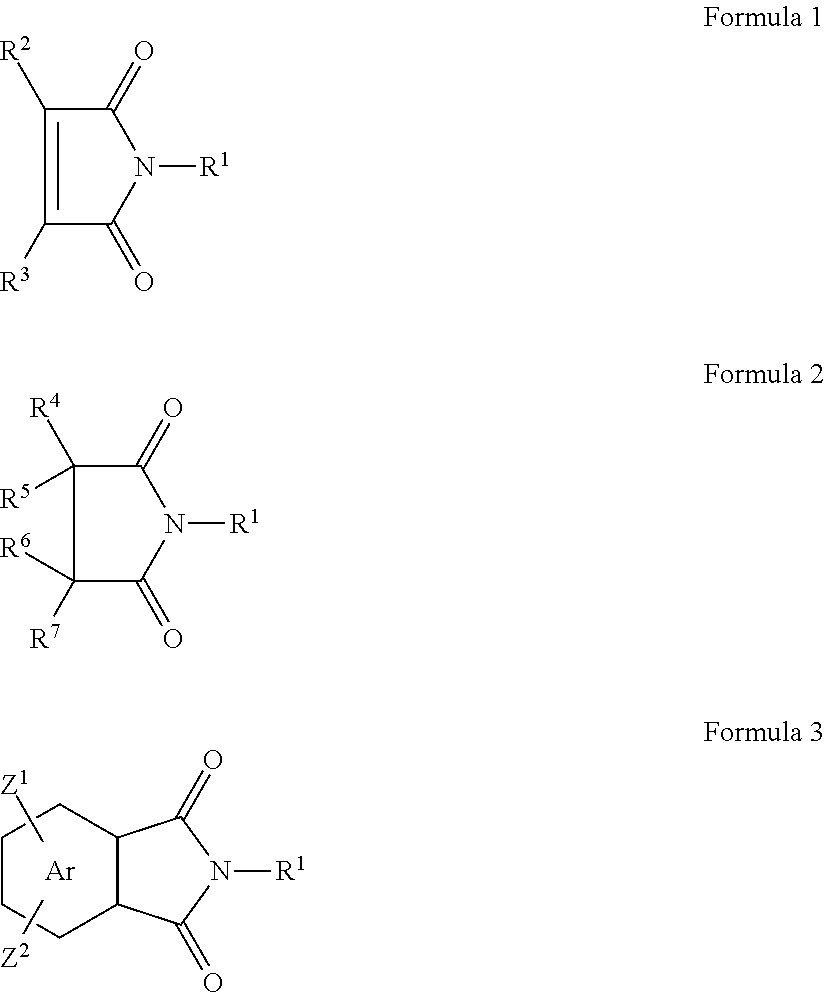
The heterocyclic imide materials can be described by three general structures, Formula 1, Formula 2 and Formula 3 shown below:
Figure US08790449-20140729-C00001
In Formula 1, the group R1 is hydrogen, alkyl, aryl, heteroalkyl, or substituted alkyl or substituted aryl. Additionally, R1 may be attached to an additional heterocyclic imide group. The groups R2 and R3 are independently hydrogen, alkyl, aryl, heteroalkyl, or substituted alkyl or substituted aryl or may be linked to another heterocyclic imide. In Formula 2, the group R1 is the same as described above. The groups R4, R5, R6 and R7 are independently hydrogen, alkyl, aryl, heteroalkyl, or substituted alkyl or substituted aryl or may be linked to another heterocyclic imide. In Formula 3, the group R1 is the same as described above; the Ar is an aromatic ring such as a phenyl, a naphthalyl, an anthracenyl or other aromatic fused ring structure; Z1 and Z2 are substituents on the aromatic ring that may be located anywhere on the aromatic ring and independently may be hydrogen, alkyl, aryl, heteroalkyl, or substituted alkyl, nitro, substituted aryl or may be linked to another heterocyclic imide. Additionally the aromatic ring may be linked to another heterocyclic imide.
In some embodiments, the charge-enhancing additive is an additive of Formula 1. A variety of different materials that are described by Formula 1 are useful as charge-enhancing additives. Such additives are sometimes referred to as “maleimides” because when R1, R2 and R3 in Formula 1 are hydrogen atoms, the molecule is known as maleimide. Typically the groups R2 and R3 are hydrogen atoms. Suitable maleimides include, for example, maleimides which are linked to another maleimide group. Such maleimides include examples where R1 in Formula 1 is a linking group attached to another maleimide group. Examples of linking groups include alkylene groups, arylene groups, aralkylene groups and the like. In some embodiments the linking group comprises an aromatic linking, meaning that the linking group contains at least one aromatic ring. Examples of aromatic linking groups include, for example, arylene groups (—Ar—), and a variety of aralkylene groups which may be linked through either an aryl group or an alkyl group such as for example —Ar—R8—Ar—, and —R9—Ar—R9— where R8 and R9 are alkylene groups and Ar represents an arylene group. In some embodiments the charge-enhancing additive comprises the structure of Formula 4 or Formula 5 (below).
Figure US08790449-20140729-C00002
In some embodiments, the charge-enhancing additive is an additive of Formula 2. A variety of different materials that are described by Formula 2 are useful as charge-enhancing additives. Such additives are sometimes referred to as “succinimides” because when R1, R4, R5, R6 and R7 in Formula 2 are hydrogen atoms, the molecule is known as succinimide. Suitable succinimides include, for example, succinimides of Formula 2 where R1 comprises an alkyl, aryl, heteroalkyl, substituted alkyl or substituted aryl. The R4, R5, R6 and R7 groups can be alkyl, or aryl groups or they may be linking groups that link the succinimide group to other succinimide groups. In some desirable embodiments, the charge enhancing additive is a succinimide of Formula 2 where R1 comprises a hindered amine group, the R4 and R6 groups are linking groups that link the succinimide group to other succinimide groups, and the R3 and R5 groups are hydrogens. In a particularly suitable embodiment, the charge-enhancing additive is commercially available as “UVINUL 5050H” from BASF, Ludwigshafen, Germany, which may be described as a hindered amine N-substituted succinimide oligomer. The structure of this additive is shown in Formula 6 (below) where the molecular weight is reported to be 3,000-4,000 grams/mole and the value of n is therefore about 5-7.
Figure US08790449-20140729-C00003
In some embodiments, the charge-enhancing additive is an additive of Formula 3. A variety of different materials that are described by Formula 3 are useful as charge-enhancing additives. Additives of Formula 3 may be viewed as maleimides fused to aryl groups. One suitable class of such materials are sometimes referred to as “phthalimides” because when R1, Z1 and Z2 in Formula 3 are hydrogen atoms, and the Ar group is a phenyl ring, the molecule is known as phthalimide. Suitable phthalimides include, for example, phthalimides of Formula 3 where R1 comprises an alkyl, aryl, heteroalkyl, substituted alkyl or substituted aryl. The Z1 and Z2 groups can independently be hydrogen, alkyl, aryl, or nitro groups. In some desirable embodiments, the charge enhancing additive is a phthalimide of Formula 3 where R1 comprises an aryl group such as a phenyl group, and one of the Z1 and Z2 groups is a hydrogen atom and the other is nitro group. An example of a suitable phthalimide is shown in Formula 7 (below).
Figure US08790449-20140729-C00004
Typically the charge-enhancing additive is present in a thermoplastic resin and charge-enhancing additive blend in amounts of up to about 10%, more typically in the range of 0.1 to 5% by weight based upon the total weight of the blend. In some embodiments, the charge-enhancing additive is present in an amount ranging from 0.1 to 3% by weight or 0.25 to 2% by weight.
The blend of the thermoplastic resin and the charge-enhancing additive can be prepared by well-known methods. Typically, the blend is processed using melt extrusion techniques, so the blend may be preblended to form pellets in a batch process, or the thermoplastic resin and the charge-enhancing additive may be mixed in the extruder in a continuous process. Where a continuous process is used, the thermoplastic resin and the charge-enhancing additive may be pre-mixed as solids or added separately to the extruder and allowed to mix in the molten state.
Examples of melt mixers that may be used to form preblended pellets include those that provide dispersive mixing, distributive mixing, or a combination of dispersive and distributive mixing. Examples of batch methods include those using a BRABENDER (e.g. a BRABENDER PREP CENTER, commercially available from C.W. Brabender Instruments, Inc.; South Hackensack, N.J.) or BANBURY internal mixing and roll milling equipment (e.g. equipment available from Farrel Co.; Ansonia, Conn.). After batch mixing, the mixture created may be immediately quenched and stored below the melting temperature of the mixture for later processing.
Examples of continuous methods include single screw extruding, twin screw extruding, disk extruding, reciprocating single screw extruding, and pin barrel single screw extruding. The continuous methods can include utilizing both distributive elements, such as cavity transfer mixers (e.g. CTM, commercially available from RAPRA Technology, Ltd.; Shrewsbury, England) and pin mixing elements, static mixing elements or dispersive mixing elements (commercially available from e.g., MADDOCK mixing elements or SAXTON mixing elements).
Examples of extruders that may be used to extrude preblended pellets prepared by a batch process include the same types of equipment described above for continuous processing. Useful extrusion conditions are generally those which are suitable for extruding the resin without the additive.
The extruded blend of thermoplastic resin and charge-enhancing additive may be cast or coated into films or sheets or may be melt-blown into non-woven fibrous webs using known techniques. Melt-blown, non-woven microfibrous webs are particularly useful as filtration media.
Melt-blown, non-woven microfibrous electret filters are especially useful as an air filter element of a respirator, such as a filtering facepiece, or for such purposes as home and industrial air-conditioners, air cleaners, vacuum cleaners, medical air line filters, and air conditioning systems for vehicles and common equipment, such as computers, computer disk drives and electronic equipment. In some embodiments, the electret filters are combined with a respirator assembly to form a respiratory device designed to be used by a person. In respirator uses, the electret filters may be in the form of molded, pleated, or folded half-face respirators, replaceable cartridges or canisters, or prefilters.
Melt-blown microfibers useful in the present disclosure can be prepared as described in Van A. Wente, “Superfine Thermoplastic Fibers,” Industrial Engineering Chemistry, vol. 48, pp. 1342-1346 and in Report No. 4364 of the Naval Research Laboratories, published May 25, 1954, entitled “Manufacture of Super Fine Organic Fibers” by Van A. Wente et al.
Useful melt-blown microfibers for fibrous electret filters typically have an effective fiber diameter of from about 1-100 micrometers, more typically 2 to 30 micrometers, in some embodiments from about 7 to 15 micrometers, as calculated according to the method set forth in Davies, C. N., “The Separation of Airborne Dust and Particles,” Institution of Mechanical Engineers, London, Proceedings 1B, 1952.
Staple fibers may also be present in the web. The presence of staple fibers generally provides a more lofty, less dense web than a web of only blown microfibers. Generally, no more than about 90 weight percent staple fibers are present, more typically no more than about 70 weight percent. Examples of webs containing staple fiber are disclosed in U.S. Pat. No. 4,118,531 (Hauser).
Sorbent particulate material such as activated carbon or alumina may also be included in the web. Such particles may be present in amounts up to about 80 volume percent of the contents of the web. Examples of particle-loaded webs are described, for example, in U.S. Pat. No. 3,971,373 (Braun), U.S. Pat. No. 4,100,324 (Anderson) and U.S. Pat. No. 4,429,001 (Kolpin et al.).
Various optional additives can be blended with the thermoplastic composition including, for example, pigments, light stabilizers, primary and secondary antioxidants, metal deactivators, hindered amines, hindered phenols, fatty acid metal salts, triester phosphites, phosphoric acid salts, fluorine-containing compounds and combinations thereof. In addition, other charge-enhancing additives may be combined with the thermoplastic composition. Possible charge additives include thermally stable organic triazine compounds or oligomers, which compounds or oligomers contain at least one nitrogen atom in addition to those in the triazine ring, see, for example, U.S. Pat. Nos. 6,268,495, 5,976,208, 5,968,635, 5,919,847, and 5,908,598 to Rousseau et al. Another additive known to enhance electrets is “CHIMASSORB 944 LF: (poly[[6-(1,1,3,3,-tetramethylbutyl)amino]-s-triazine-2,4-diyl][[(2,2,6,6-tetramethyl-4-piperidyl)imino]hexamethylene[(2,2,6,6-tetramethyl-4-piperidyl)imino]]), available from Ciba Specialty Chemicals, Inc. The charge-enhancing additives may be N-substituted amino aromatic compounds, particularly tri-amino substituted compounds, such as 2,4,6-trianilino-p-(carbo-2′-ethylhexyl-1′-oxy)-1,3,5-triazine commercially available as “UVINUL T-150” from BASF, Ludwigshafen, Germany. Another charge additive is 2,4,6-tris-(octadecylamino)-triazine, also known as tristearyl melamine (“TSM”). Further examples of charge-enhancing additives are provided in U.S. Patent Application Ser. No. 61/058,029, U.S. Patent Application Ser. No. 61/058,041, U.S. Pat. No. 7,390,351 (Leir et al.), U.S. Pat. No. 5,057,710 (Nishiura et al.), and U.S. Pat. Nos. 4,652,282 and 4,789,504 (Ohmori et al.).
In addition the web may be treated to chemically modify its surface. Surface fluorination can be achieved by placing a polymeric article in an atmosphere that contains a fluorine-containing species and an inert gas and then applying an electrical discharge to modify the surface chemistry of the polymeric article. The electrical discharge may be in the form of a plasma such as an AC corona discharge. This plasma fluorination process causes fluorine atoms to become present on the surface of the polymeric article. The plasma fluorination process is described in a number of U.S. Pat. Nos. 6,397,458, 6,398,847, 6,409,806, 6,432,175, 6,562,112, 6,660,210, and 6,808,551 to Jones/Lyons et al. Electret articles that have a high fluorosaturation ratio are described in U.S. Pat. No. 7,244,291 to Spartz et al., and electret articles that have a low fluorosaturation ratio, in conjunction with heteroatoms, is described in U.S. Pat. No. 7,244,292 to Kirk et al. Other publications that disclose fluorination techniques include: U.S. Pat. Nos. 6,419,871, 6,238,466, 6,214,094, 6,213,122, 5,908,598, 4,557,945, 4,508,781, and 4,264,750; U.S. Publications US 2003/0134515 A1 and US 2002/0174869 A1; and International Publication WO 01/07144.
The electret filter media prepared according to the present disclosure generally have a basis weight (mass per unit area) in the range of about 10 to 500 g/m2, and in some embodiments, about 10 to 100 g/m2. In making melt-blown microfiber webs, the basis weight can be controlled, for example, by changing either the collector speed or the die throughput. The thickness of the filter medium is typically about 0.25 to 20 millimeters, and in some embodiments, about 0.5 to 2 millimeters. Multiple layers of fibrous electret webs are commonly used in filter elements. The solidity of the fibrous electret web typically is about 1% to 25%, more typically about 3% to 10%. Solidity is a unitless parameter that defines the solids fraction of the web. Generally the methods of this disclosure provide electret webs with generally uniform charge distribution throughout the web without regard to basis weight, thickness, or solidity of the medium. The electret filter medium and the resin from which it is produced should not be subjected to any unnecessary treatment which might increase its electrical conductivity, e.g., exposure to ionizing radiation, gamma rays, ultraviolet irradiation, pyrolysis, oxidation, etc.
The electret web may be charged as it is formed or the web may be charged after the web is formed. In electret filter media, the medium is generally charged after the web is formed. In general, any standard charging method known in the art may be used. For example, charging may be carried out in a variety of ways, including tribocharging, DC corona discharge and hydrocharging. A combination of methods may also be used.
Examples of suitable DC corona discharge processes are described in U.S. Pat. Re. No. 30,782 (van Turnhout), U.S. Pat. Re. No. 31,285 (van Turnhout), U.S. Pat. Re. No. 32,171 (van Turnhout), U.S. Pat. No. 4,215,682 (Davis et al.), U.S. Pat. No. 4,375,718 (Wadsworth et al.), U.S. Pat. No. 5,401,446 (Wadsworth et al.), U.S. Pat. No. 4,588,537 (Klaase et al.), U.S. Pat. No. 4,592,815 (Nakao), and U.S. Pat. No. 6,365,088 (Knight et al.).
Hydrocharging of the web is carried out by impinging jets of water or a stream of water droplets onto the web at a pressure sufficient to provide the web with filtration enhancing electret charge. The pressure necessary to achieve optimum results varies depending on the type of sprayer used, the type of polymer from which the web is formed, the type and concentration of additives to the polymer, the thickness and density of the web and whether pre-treatment, such as DC corona surface treatment, was carried out prior to hydrocharging. Generally, water pressures in the range of about 10 to 500 psi (69 to 3450 kPa) are suitable. DC corona surface treatment could also be used as a post-hydrocharging treatment, if desired, but such a post-treatment is not typical.
The jets of water or stream of water droplets can be provided by any suitable spray means. An apparatus useful for hydraulically entangling fibers is generally useful in the method of the present disclosure, although operation is carried out at lower pressures in hydrocharging than generally used in hydroentangling. Hydrocharging is understood to include the method described in U.S. Pat. No. 5,496,507 (Angadjivand) and other various derivative methods for imparting an electret charge using the fluid wetting and dewetting process as described in, for example, Japanese Patent Application Number JP 2002161467 (Horiguchi), Japanese Patent Application Number JP 2002173866 (Takeda), Japanese Patent Application Number JP 2002115177 (Takeda), Japanese Patent Application Number JP 2002339232 (Takeda), Japanese Patent Application Number JP 2002161471 (Takeda), Japanese Pat. No. 3,780,916 (Takeda), Japanese Patent Application Number JP 2002115178 (Takeda), Japanese Patent Application Number JP 2003013359 (Horiguchi), U.S. Pat. No. 6,969,484 (Horiguchi), U.S. Pat. No. 6,454,986 (Eitzman), Japanese Patent Application Number JP 2004060110 (Masumori), Japanese Patent Application Number JP 2005131485 (Kodama), and Japanese Patent Application Number JP 2005131484 (Kodama).
The hydrocharging of the web may also be carried out using a new method disclosed in the U.S. patent application entitled “Method of Making Electret Articles Based On Zeta Potential” (U.S. Ser. No. 12/131,770) filed Jun. 2, 2008. The method comprises: (a) providing a polymeric article to be charged; and (b) contacting the polymeric article to be charged with an aqueous liquid that has a pH and conductivity as follows: (i) if the article has a zeta potential of less than −7.5 millivolts (mV), then the contacting water has a conductivity of about 5 to 9,000 microSiemens per centimeter (microS/cm) and a pH greater than 7; and (ii) if the article has a zeta potential of greater than −7.5 mV, then the contacting water has a conductivity of about 5 to 5,500 micro Siemens per centimeter (microS/cm) and a pH of 7 or less. The article may be dried actively (with a vacuum or heat) or passively (hang drying) or combinations thereof.
To assess filtration performance, a variety of filtration testing protocols have been developed. These tests include measurement of the aerosol penetration of the filter web using a standard challenge aerosol such as dioctylphthalate (DOP), which is usually presented as percent of aerosol penetration through the filter web (% Pen) and measurement of the pressure drop across the filter web (ΔP). From these two measurements, a quantity known as the Quality Factor (QF) may be calculated by the following equation:
QF=−ln(% Pen/100)/ΔP,
where ln stands for the natural logarithm. A higher QF value indicates better filtration performance, and decreased QF values effectively correlate with decreased filtration performance. Details for measuring these values are presented in the Examples section. Typically, the filtration media of this disclosure have measured QF values of 0.3 (mm of H2O)−1 or greater at a face velocity of 6.9 centimeters per second.
To verify that a particular filter medium is electrostatically charged in nature, one may examine its performance before and after exposure to ionizing X-ray radiation. As described in the literature, for example, Air Filtration by R. C. Brown (Pergamon Press, 1993) and “Application of Cavity Theory to the Discharge of Electrostatic Dust Filters by X-Rays”, A. J. WAKER and R. C. BROWN, Applied Radiation and Isotopes, Vol. 39, No. 7, pp. 677-684, 1988, if an electrostatically charged filter is exposed to X-rays, the penetration of an aerosol through the filter will be greater after exposure than before exposure, because the ions produced by the X-rays in the gas cavities between the fibers will have neutralized some of the electric charge. Thus, a plot of penetration against cumulative X-ray exposure can be obtained which shows a steady increase up to a constant level after which further irradiation causes no change. At this point all of the charge has been removed from the filter.
These observations have led to the adoption of another testing protocol to characterize filtration performance, the X-ray Discharge Test. In this testing protocol, select pieces of the filter medium to be tested are subjected to X-ray radiation to discharge the electret web. One attribute of this test is that it confirms that the web is an electret. Because it is known that X-rays quench electret charge, exposure of a filter media to X-rays and measuring the filter performance before and after this exposure and comparing the filter performances indicates whether the filter media is an electret. If the filter performance is unchanged after exposure to X-ray radiation, that is indicative that no charge was quenched and the material is not an electret. However, if the filter performance diminishes after exposure to X-ray radiation, that is indicative that the filter media is an electret.
When the test is run, typically, the filtration performance is measured before and after exposure of the filter medium to the X-ray radiation. A % Penetration Ratio can be calculated according to the following equation: % Penetration Ratio=(ln(initial % DOP Penetration/100)/(ln(% DOP Penetration after 60 min of X-ray exposure)))×100, when tested according to the Filtration Performance Test Method, as described in the Examples section below. In order for the web to have sufficient charge for use as a filter, the % Penetration Ratio is typically at least 300%. As the % Penetration Ratio increases, the filtration performance of the web also increases. In some embodiments, the % Penetration Ratio is at least 400%, 500%, or 600%. In preferred embodiments, the % Penetration Ratio is at least 750% or 800%. In some embodiments, the web exhibits a % Penetration Ratio of at least 1000%, or at least 1250%.
The initial Quality Factor (prior to exposure to X-rays) is typically at least 0.3 (mm of H2O)−1, more typically at least 0.4 or even 0.5 (mm of H2O)−1 for a face velocity of 6.9 cm/s when tested according to the Filtration Performance Test Method, as described in the Examples section below. In some embodiments, the initial Quality Factor is at least 0.6 or 0.7 (mm of H2O)−1. In other embodiments, the initial Quality Factor is at least 0.8, at least 0.90, at least 1.0, or even greater than 1.0 (mm of H2O)−1. The Quality Factor after 60 minutes exposure to X-rays is typically less than 50% of the initial Quality Factor. In some embodiments, the initial Quality Factor is at least 0.5 (mm of H2O)−1 or greater and the Quality Factor after 60 minutes exposure to X-rays is less than 0.15 (mm of H2O)−1.
The Effective Charge Density (qf) for an electret filter fiber may be calculated from filter penetration test measurements. This calculation is described in Brown, R. C. (1981) Capture of Dust Particles in Filters by Line-Dipole Charged Fibers, J. Aerosol Sci. 12:349-356; and Otani, Y., Emi, H., and Mori, J. (1993), Initial Collection Efficiency of Electret Filter and Its Durability for Solid and Liquid Particles, J. Chem. Eng. Japan 11:207-214.
The equation for filter penetration through an electret filter medium is related to three particle coefficients for mechanical, dipole and coulombic particle capture mechanisms.
% P ch = 100 [ π ( 1 - α ) d f 4 α L ] ( η M + η I n + η c ) ,
Where:
ηm=single fiber efficiency: mechanical capture (uncharged fibers, uncharged particles)
ηIn=single fiber efficiency: induced dipole capture (charged fibers, uncharged particles)
ηC=single fiber efficiency: coulombic capture (charged fibers, charged particles)=0 for uncharged particles
The induced force single fiber efficiency (ηIn) may be calculated from the filter structure and the results of filter tests, using uncharged particles (ηC=0) for an electret filter medium, which give the penetration fraction for charged fibers (Pch) and for uncharged fibers (Punch):
η In = [ π ( 1 - α ) d f 4 α L ] ln [ P ch P unch ]
The Induced Force Dimensionless Parameter (KIn) relates to the capture of uncharged particles with charged electret fibers.
K In = [ ɛ p - 1 ɛ p + 2 ] C c π 2 q f 2 d p 2 6 ɛ 0 ( 1 + ɛ f ) 2 μ d f U 0
Correlative relationships from computational analysis (below) from Otani (1993) and Brown (1993) for two regimes may be inverted to calculate the Induced Force Parameter, KIn, from ηIn with a correction (hk) for the flow field around fibers. In the case of this study, KIn<1 and the first equation was used.
ηIn=0.51h k −0.35 K In 0.73; 10−2 <K In<100
ηIn=0.54h k −0.60 K In 0.40; 100 <K In<102
h k=−½ ln α+α−¼α2−¾
Substituting the value from the calculation of KIn from ηIn and inverting the equation for KIn above gives the Effective Charge Density (qf) of the fibers in an electret filter.
q f = { [ ɛ p + 2 ɛ p - 1 ] 6 ɛ 0 ( 1 + ɛ f ) 2 μ d f U o K In C c π 2 d p 2 } 0.5
Where:
ηIn=Induced dipole single fiber efficiency (−)
df=Fiber Diameter (m)=0.5×(Effective Fiber Diameter from airflow tests)
L=Filter thickness (m)
α=solidity (−)
Pch=Penetration—charged fibers (−)
Punch=Penetration—uncharged fibers (−)
dp=Particle Diameter (m)=0.2 micrometer
Cc=Particle Cunningham Correction Factor (−)
hk=Kuwabara hydrodynamic factor (−)
qf=Effective Fiber Charge Density (C/m2)
p=Dielectric Constant—Particle (−)=5.1 for dioctylphthalate
0=Free Space Dielectric Constant=8.8542E-12 (C2/Nm2)
f=Dielectric Constant—Fiber (−)=2.2 for polypropylene
μ=Air Viscosity Pa s=1.81E-05 (Ns/m2)
U0=Face Velocity (m/s)=6.9 cm/s
KIn=Induced Dipole Force Parameter (−)
The input DOP particle size distribution used from the TSI AFT Model 8130 aerosol generator (described below) has a geometric count mean diameter of 0.2 micrometers with a geometric standard deviation of 1.6. The TSI AFT Model 8130 was operated with the aerosol neutralizer turned off. The design of the TSI AFT Model 8130 DOP aerosol generator has a large dead-space volume. The resulting physical and electrostatic agglomeration on this liquid aerosol in the dead-space volume produces an aerosol with a very low bipolar electrostatic charge. This bipolar charge approximates zero as for uncharged particles and is much lower than with the neutralizer turned on (Boltzmann charge distribution).
The count median fiber diameter is used for the calculation of fiber charge. This is calculated as one-half the effective fiber diameter. The effective fiber diameter (EFD) is the surface area fiber diameter and can be related to the fiber count diameter by the Hatch-Choate equation:
d g = d a exp ( 2 ln 2 ( σ g ) )
Where:
dg=count geometric mean diameter=arithmetic median diameter
da=area geometric mean diameter=EFD
σg=geometric standard deviation
Details of the procedure for carrying out the calculation are included in the Examples section, below. In some embodiments, the calculated effective charge density is at least 20 microcoulombs/square meter. In other embodiments the calculated effective charge density is at least 30, 40 or even 50 microcoulombs/square meter.
EXAMPLES
These examples are merely for illustrative purposes only and are not meant to be limiting on the scope of the appended claims. All parts, percentages, ratios, etc. in the examples and the rest of the specification are by weight, unless noted otherwise. Solvents and other reagents used were obtained from Sigma-Aldrich Chemical Company; Milwaukee, Wis. unless otherwise noted.
Table of Abbreviations
Abbreviation
or Trade
Designation Description
Charge 4-Nitro-N-phenylphthalimide (CAS:40392-27-6)
Additive-1 commercially available from TCI America.
Charge N,N′-1,4-Phenylenedimaleimide (CAS:3278-31-7)
Additive-2 available from TCI America.
Charge 4,4′-Bismaleimido diphenylmethane (CAS:13676-54-5)
Additive-3 available from TCI America.
Charge 1-(2,2,6,6-tetramethyl-piperidin-4-yl)-pyrrolidine-
Additive-4 2,5-dione derivative commercially available as
“UVINUL 5050H” (CAS:152261-33-1)
from BASF, Ludwigshafen, Germany.
Charge N,N′-bisformyl-N,N′-bis(2,2,6,6-tetramethyl-
Additive-5 4-piperidinyl)-hexamethylendiamine commercially
available as “UVINUL 4050H”(CAS:124172-53-8)
from BASF, Ludwigshafen, Germany.
PP-1 Polypropylene resin, ESCORENE PP 3746G
(melt flow index 1200), commercially available
from Exxon-Mobil Corporation, Irving, TX.
PP-2 Polypropylene resin grade 3, TOTAL PP3960
(melt flow index 350), commercially available
from Total Petrochemicals USA Inc., Houston, TX.
PP-3 Polypropylene resin, TOTAL PP3860
(melt flow index 100), commercially available
from Total Petrochemicals USA Inc., Houston, TX.
PP-4 Polypropylene resin, METOCENE MF 650W
(melt flow index 500), commercially available
from LyondellBasell Industries, Inc.,
Rotterdam, Netherlands
PP-5 Polypropylene resin, TOTAL PP3868
(melt flow index 35), commercially available
from Total Petrochemicals USA Inc., Houston, TX.
PMP-1 Poly-4-methyl-1-pentene resin, TPX-MX002,
commercially available from Mitsui
Chemicals, Inc., Tokyo, Japan
DI water Deionized water
PPM Parts per million
BMF Melt blown microfiber web

Test Methods
Filtration Testing
The samples were tested for % DOP aerosol penetration (% Pen) and pressure drop (ΔP), and the Quality Factor (QF) was calculated. The filtration performance (% Pen and QF) of the nonwoven microfiber webs were evaluated using an Automated Filter Tester (AFT) Model 8130 (available from TSI, Inc., St. Paul, Minn.) using dioctylphthalate (DOP) as the challenge aerosol. The DOP aerosol is nominally a monodisperse 0.3 micrometer mass median diameter having an upstream concentration of 70-120 mg/m3. The aerosol was forced through a sample of filter media at a calibrated flow rate of 42.5 liters/minute (face velocity of 6.9 cm/s) with the aerosol TSI AFT Model 8130 aerosol neutralizer turned off. The total testing time was 23 seconds (rise time of 15 seconds, sample time of 4 seconds, and purge time of 4 seconds). Simultaneously with % Pen, the pressure drop (ΔP in mm of water) across the filter was measured by the instrument. The concentration of DOP aerosol was measured by light scattering both upstream and downstream of the filter media using calibrated photometers. The DOP % Pen is defined as: % Pen=100×(DOP concentration downstream/DOP concentration upstream). For each material, 6 separate measurements were made at different locations on the BMF web and the results were averaged.
The % Pen and ΔP were used to calculate a QF by the following formula:
QF=−ln(% Pen/100)/ΔP,
where ln stands for the natural logarithm. A higher QF value indicates better filtration performance and decreased QF values effectively correlate with decreased filtration performance.
X-ray Discharge Test
The Quality Factor and % Penetration of sample webs to be tested were determined prior to exposure to X-ray radiation using the test method described above. The Initial Quality Factor is designated as “QF0”. The sample web was exposed on each side to X-rays using the system described below, ensuring that the entire sample was uniformly exposed to the X-ray radiation. After X-ray exposure, the sample of filter media was tested again to measure its filter performance (QF and % Pen). The procedure was repeated until the filter performance reached a plateau value, indicating all of the sample's electrostatic charge had been neutralized. The % Penetration Ratio (% Pen Ratio) is also reported. The % Pen Ratio was calculated from the % Pen at 0 minutes and 60 minutes using the equation where ln stands for the natural logarithm:
% Pen Ratio = ln ( % Pen ( 0 min ) / 100 ) ln ( % Pen ( 60 min ) / 100 ) × 100 % .
X-ray exposure was carried out using a Baltograph 100/15 CP (Balteau Electric Corp., Stamford, Conn.) X-ray exposure system consisting of a constant potential end grounded generator rated at 100 KV at 10 mA with a beryllium window (0.75 mm inherent filtration) with an output of up to 960 Roentgen/min at 50 cm from the focal spot of 1.5 mm×1.5 mm was employed. The voltage was set to 80 KV with a corresponding current of 8 mA. A sample holder was set up at an approximate distance of 57.2 centimeters (22.5 inches) from the focal spot to produce an exposure of about 580 Roentgen/min.
Effective Charge Density Calculation:
The Effective Charge Density (qf) for an electret filter fiber was calculated from filter penetration test measurements. The equation for filter penetration through an electret filter medium is related to three particle coefficients for mechanical, dipole and coulombic particle capture mechanisms.
% P ch = 100 [ π ( 1 - α ) d f 4 α L ] ( η M + η l n + η c ) ,
Where:
ηM=single fiber efficiency: mechanical capture (uncharged fibers, uncharged particles)=
ηIn=single fiber efficiency: induced dipole capture (charged fibers, uncharged particles)
ηC=single fiber efficiency: coulombic capture (charged fibers, charged particles)=0 for uncharged particles
The induced force single fiber efficiency (ηIn) may be calculated from the filter structure and the results of filter tests, using uncharged particles (ηC=0) for an electret filter medium, which give the penetration fraction for charged fibers (Pch) and for uncharged fibers (Punch):
η l n = [ π ( 1 - α ) d f 4 α L ] ln [ P ch P unch ]
The Induced Force Dimensionless Parameter (KIn) relates to the capture of uncharged particles with charged electret fibers.
K In = [ ɛ p - 1 ɛ p + 2 ] C c π 2 q f 2 d p 2 6 ɛ 0 ( 1 + ɛ f ) 2 μ d f U 0
Correlative relationships from computational analysis (below) from Otani (1993) and Brown (1993) for two regimes may be inverted to calculate the Induced Force Parameter, KIn, from ηIn with a correction (hk) for the flow field around fibers. In the case of this study, KIn<1 and the first equation was used.
ηIn=0.51h k −0.35 K In 0.73; 10−2 <K In<100
ηIn=0.54h k 0.60 K In 0.40; 100 <K In<102
h k=−½ ln α+α−¼α2−¾
Substituting the value from the calculation of KIn from ηIn and inverting the equation for KIn above gives the Effective Charge Density (qf) of the fibers in an electret filter.
q f = { [ ɛ p + 2 ɛ p - 1 ] 6 ɛ 0 ( 1 + ɛ r ) 2 μ d f U o K In C c π 2 d p 2 } 0.5
Where:
ηIn=Induced dipole single fiber efficiency (−)
df=Fiber Diameter (m)=0.5×(Effective Fiber Diameter from airflow tests)
L=Filter thickness (m)
α=solidity (−)
Pch=Penetration—charged fibers (−)
Punch=Penetration—uncharged fibers (−)
dp=Particle Diameter (m)=0.2 micrometer
Cc=Particle Cunningham Correction Factor (−)
hk=Kuwabara hydrodynamic factor (−)
qf=Effective Fiber Charge Density (C/m2)
p=Dielectric Constant—Particle (−)=5.1 for dioctylphthalate
0=Free Space Dielectric Constant=8.8542E-12 (C2/Nm2)
f=Dielectric Constant—Fiber (−)=2.2 for polypropylene
μ=Air Viscosity Pa s=1.81E-05 (Ns/m2)
U0=Face Velocity (m/s)=6.9 cm/s
KIn=Induced Dipole Force Parameter (−)
The input particle size distribution used from the TSI AFT Model 8130 aerosol generator has a geometric count mean diameter of 0.2 micrometers with a geometric standard deviation of 1.6.
The count median fiber diameter is used for the calculation of fiber charge. This is calculated as one-half the effective fiber diameter. The effective fiber diameter (EFD) is the surface area fiber diameter and can be related to the fiber count diameter by the Hatch-Choate equation:
d g = d a exp ( 2 ln 2 ( σ g ) )
Where:
dg=count geometric mean diameter=arithmetic median diameter
da=area geometric mean diameter=EFD
σg=geometric standard deviation
Thermal Stability Analysis:
The thermal stability of each charging additive was measured with a Thermogravimetric Analyzer (TGA) Model 2950 available from TA Instruments, New Castle, Del. Approximately 5-10 milligrams of material was placed in the TGA and heated from room temperature to 500° C. at a rate of 10° C./min under an air environment while the weight loss was measured. Table 1 lists the temperature at which 2% weight loss was detected as well as the temperature at which 5% weight loss was detected.
TABLE 1
Temperature at Temperature at
Charging 2% weight loss 5% weight loss
Additive (° C.) (° C.)
1 236 253
2 234 252
3 272 444
4 268 335
5 265 289
Examples 1-85 and Comparative Examples C1-C83
For each of the Examples and Comparative Examples, the procedures described below were followed. The data for these Examples are presented in Tables 2, 3 and 4.
Sample Preparation:
Step A—Preparation of Microfiber Webs:
For each Example Web 1-20, one of the charging additives described above (either Additive 1, 2, 3, or 4) was selected and dry blended with one of the grades of polypropylene or poly-4-methyl-1-pentene at the concentration shown in Table 2, and the blend was extruded as described in Van A. Wente, “Superfine Thermoplastic Fibers,” Industrial Engineering Chemistry, vol. 48, pp. 1342-1346. The extrusion temperature ranged from about 250° C.-340° C. and the extruder was a BRABENDER conical twin-screw extruder (commercially available from Brabender Instruments, Inc.) operating at a rate of about 2.5 to 3 kg/hr (5-7 lb/hr). The die was 25.4 centimeters (10 inches) wide with 10 holes per centimeter (25 holes per inch). Melt blown microfiber (BMF) webs were formed having basis weights of about 57 g/m2, effective fiber diameters of about 8.0 micrometers and a thickness of about 1 millimeter. Likewise, for each Comparative Example C1-C8, a BMF web was prepared from the same grade of polypropylene as the corresponding Examples web, but either no charge additive was added or the Charging Additive 5 was used. Table 2 summarizes the specific web characteristics for each of the Examples and Comparative Examples.
Step B—Electret Preparation:
Each of the BMF webs prepared in Step A above was charged by one of four electret charging methods: corona pre-treatment and hydrocharging with water containing 50 PPM Na2CO3; corona pre-treatment and hydrocharging with DI water; hydrocharging with water containing 50 PPM Na2CO3; or hydrocharging with DI water. Table 3 summarizes the specific charging method applied to each of the samples.
Charging Method 1:
The selected BMF webs prepared in Step A above were charged by DC corona discharge followed by hydrocharging with water containing 50 PPM Na2CO3. The corona charging was accomplished by passing the web on a grounded surface under a corona brush source with a corona current of about 0.01 milliamp per centimeter of discharge source length at a rate of about 3 centimeters per second. The corona source was about 3.5 centimeters above the grounded surface on which the web was carried. The corona source was driven by a positive DC voltage. After the corona charging, the BMF web was hydrocharged using a fine spray of water having 50 PPM Na2CO3 dissolved in it generated from a nozzle operating at a pressure of 896 kiloPascals (130 psig) and a flow rate of approximately 1.4 liters/minute. The selected BMF webs prepared in Step A were conveyed by a porous belt through the water spray at a speed of approximately 10 centimeters/second while a vacuum simultaneously drew the water through the web from below. Each BMF web was run through the hydrocharger twice (sequentially once on each side) while spraying, and then twice without spraying with just the vacuum to remove any excess water. The webs were allowed to dry completely in air overnight prior to filter testing.
Charging Method 2:
The selected BMF webs prepared in Step A above were charged by DC corona discharge followed by hydrocharging with DI water. The same method was used as in Charging Method 1 except DI water was used instead of water containing 50 PPM Na2CO3 dissolved in it.
Charging Method 3:
The selected BMF webs prepared in Step A above were charged by hydrocharging with water containing 50 PPM Na2CO3. The BMF web was hydrocharged using a fine spray of water having 50 PPM Na2CO3 dissolved in it generated from a nozzle operating at a pressure of 896 kiloPascals (130 psig) and a flow rate of approximately 1.4 liters/minute. The selected BMF webs prepared in Step A were conveyed by a porous belt through the water spray at a speed of approximately 10 centimeters/second while a vacuum simultaneously drew the water through the web from below. Each BMF web was run through the hydrocharger twice (sequentially once on each side) while spraying, and then twice without spraying with just the vacuum to remove any excess water. The webs were allowed to dry completely in air overnight prior to filter testing.
Charging Method 4:
The selected BMF webs prepared in Step A above were charged by hydrocharging with DI water. The BMF web was hydrocharged using a fine spray of DI water generated from a nozzle operating at a pressure of 896 kiloPascals (130 psig) and a flow rate of approximately 1.4 liters/minute. The selected BMF webs prepared in Step A were conveyed by a porous belt through the water spray at a speed of approximately 10 centimeters/second while a vacuum simultaneously drew the water through the web from below. Each BMF web was run through the hydrocharger twice (sequentially once on each side) while spraying, and then twice without spraying with just the vacuum to remove any excess water. The webs were allowed to dry completely in air overnight prior to filter testing.
Filtration Testing Procedure:
Initial Filtration Performance:
Each of the charged samples prepared in Step B above was cut into a 1 meter section, this section was tested in its initial state for % DOP aerosol penetration (% DOP Pen) and pressure drop (ΔP), and the Quality Factor (QF) was calculated as described in the Test Methods given above. These results are reported in Table 3 below as % DOP Pen, Pressure Drop and QF.
TABLE 2
BMF Web Additive Eff. Fiber
Example Charge Resin Concn. Diam. Solidity Basis Weight Thickness
number Additive Grade (wt %) (μm) (%) (g/m2) (mm)
C1 None PP-1 0 8.0 5.5 57 1.13
 1 1 PP-1 0.5 8.4 4.8 52 1.19
 2 1 PP-1 1 7.7 4.6 56 1.31
 3 2 PP-1 0.5 8.2 4.5 53 1.28
 4 3 PP-1 0.5 8.1 4.6 59 1.38
 5 3 PP-1 1 8.4 4.3 57 1.44
 6 4 PP-1 0.5 8.1 5.4 56 1.11
 7 4 PP-1 1 8.1 5.8 55 1.03
C2 5 PP-1 0.5 8.0 5.3 55 1.14
C3 5 PP-1 1 8.1 5.6 55 1.06
C4 None PP-2 0 8.3 6.0 56 1.01
 8 4 PP-2 0.5 7.7 6.1 59 1.05
 9 4 PP-2 1.0 7.9 5.9 62 1.15
C5 None PP-3 0 8.1 5.4 60 1.20
10 4 PP-3 0.1 7.9 5.9 58 1.09
11 4 PP-3 0.2 8.3 6.1 60 1.08
12 4 PP-3 0.5 8.2 6.1 60 1.08
13 4 PP-3 0.75 8.1 6.2 57 1.01
14 4 PP-3 1.0 7.9 6.1 59 1.04
C6 None PP-4 0 7.6 5.4 56 1.14
15 4 PP-4 0.5 7.8 6.4 60 1.01
16 4 PP-4 1.0 7.7 6.4 56 0.96
C7 None PP-5 0 8.3 56 7.1 0.85
17 4 PP-5 0.5 7.7 58 7.5 0.85
18 4 PP-5 1 7.5 57 6.7 0.93
C8 None PMP-1 0 8.1 55 7.3 0.89
19 4 PMP-1 0.5 9.3 58 7.8 0.88
20 4 PMP-1 1 9.2 55 7.4 0.88
TABLE 3
Additive BMF Web Pressure
Example Charge concn. Resin Example Charging % DOP Drop QF
Number Additive (wt %) Grade Number Method Pen. (mm H2O) (1/mm H2O)
21 1 0.5 PP-1 1 1 3.58 1.86 1.80
C9  None None PP-1 C1 1 8.92 2.14 1.14
22 1 0.5 PP-1 1 2 8.88 1.78 1.37
C10 None None PP-1 C1 2 16.2 2.14 0.86
23 1 0.5 PP-1 1 3 5.73 1.84 1.57
C11 None None PP-1 C1 3 29.1 2.12 0.59
24 1 0.5 PP-1 1 4 12.52 1.74 1.20
C12 None None PP-1 C1 4 44.4 2.16 0.38
25 1 1   PP-1 2 1 4.62 2.02 1.53
C13 None None PP-1 C1 1 8.92 2.14 1.14
26 1 1   PP-1 2 2 10.64 2.14 1.06
C14 None None PP-1 C1 2 16.2 2.14 0.86
27 1 1   PP-1 2 3 3.66 2.12 1.56
C15 None None PP-1 C1 3 29.1 2.12 0.59
28 1 1   PP-1 2 4 10.64 2.14 0.88
C16 None None PP-1 C1 4 44.4 2.16 0.38
29 2 0.5 PP-1 3 1 5.04 1.52 1.98
C17 None None PP-1 C1 1 8.92 2.14 1.14
30 2 0.5 PP-1 3 2 10.81 1.52 1.47
C18 None None PP-1 C1 2 16.2 2.14 0.86
31 2 0.5 PP-1 3 3 29.3 1.58 0.78
C19 None None PP-1 C1 3 29.1 2.12 0.59
32 2 0.5 PP-1 3 4 51.1 1.44 0.47
C20 None None PP-1 C1 4 44.4 2.16 0.38
33 3 0.5 PP-1 4 1 7.13 1.80 1.47
C21 None None PP-1 C1 1 8.92 2.14 1.14
34 3 0.5 PP-1 4 2 18.34 1.74 0.98
C22 None None PP-1 C1 2 16.2 2.14 0.86
35 3 0.5 PP-1 4 3 27.14 1.76 0.75
C23 None None PP-1 C1 3 29.1 2.12 0.59
36 3 1   PP-1 5 1 4.66 1.66 1.87
C24 None None PP-1 C1 1 8.92 2.14 1.14
37 3 1   PP-1 5 2 11.77 1.66 1.32
C25 None None PP-1 C1 2 16.2 2.14 0.86
38 3 1   PP-1 5 3 33.22 1.60 0.69
C26 None None PP-1 C1 3 29.1 2.12 0.59
39 3 1   PP-1 5 4 49.52 1.58 0.45
C27 None None PP-1 C1 4 44.4 2.16 0.38
40 4 0.5 PP-1 6 1 2.58 2.02 1.81
C28 None None PP-1 C1 1 8.92 2.14 1.14
C29 5 0.5 PP-1 C2 1 16.9 2.24 0.80
41 4 0.5 PP-1 6 2 4.03 1.94 1.68
C30 None None PP-1 C1 2 16.2 2.14 0.86
C31 5 0.5 PP-1 C2 2 26.43 2.38 0.56
42 4 0.5 PP-1 6 3 5.72 1.90 1.52
C32 None None PP-1 C1 3 29.1 2.12 0.59
C33 5 0.5 PP-1 C2 3 41.9 2.32 0.38
43 4 0.5 PP-1 6 4 1.33 1.92 2.26
C34 None None PP-1 C1 4 44.4 2.16 0.38
C35 5 0.5 PP-1 C2 4 29.42 2.54 0.48
44 4 1   PP-1 7 1 3.11 2.08 1.69
C36 None None PP-1 C1 1 8.92 2.14 1.14
C37 5 1   PP-1 C3 1 35.3 2.10 0.50
45 4 1   PP-1 7 2 3.66 1.98 1.67
C38 None None PP-1 C1 2 16.2 2.14 0.86
C39 5 1   PP-1 C3 2 27.3 2.18 0.60
46 4 1   PP-1 7 3 4.48 1.96 1.59
C40 None None PP-1 C1 3 29.1 2.12 0.59
C41 5 1   PP-1 C3 3 43.8 2.18 0.38
47 4 1   PP-1 7 4 0.79 2.14 2.29
C42 None None PP-1 C1 4 44.4 2.16 0.38
C43 5 1   PP-1 C3 4 29.88 2.26 0.54
48 4 0.5 PP-2 8 1 1.79 2.53 1.61
C44 None None PP-2 C4 1 27.1 2.08 0.63
49 4 0.5 PP-2 8 2 1.25 2.55 1.78
C45 None None PP-2 C4 2 40.08 1.77 0.52
50 4 0.5 PP-2 8 3 2.28 2.63 1.45
C46 None None PP-2 C4 3 54.32 1.98 0.31
51 4 0.5 PP-2 8 4 0.41 2.52 2.21
C47 None None PP-2 C4 4 70.87 1.97 0.18
52 4 1   PP-2 9 1 1.14 2.63 1.70
C48 None None PP-2 C4 1 27.1 2.08 0.63
53 4 1   PP-2 9 2 0.52 2.55 2.08
C49 None None PP-2 C4 2 40.08 1.77 0.52
54 4 1   PP-2 9 3 2.39 2.37 1.60
C50 None None PP-2 C4 3 54.32 1.98 0.31
55 4 1   PP-2 9 4 0.32 2.47 2.35
C51 None None PP-2 C4 4 70.87 1.97 0.18
56 4 0.1 PP-3 10  1 3.51 2.56 1.37
C52 None None PP-3 C5 1 4.51 2.54 1.23
57 4 0.1 PP-3 10  2 5.73 2.36 1.23
C53 None None PP-3 C5 2 8.55 2.56 0.96
58 4 0.1 PP-3 10  3 26.34 2.4 0.56
C54 None None PP-3 C5 3 42.34 2.42 0.36
59 4 0.1 PP-3 10  4 8.17 2.36 1.07
C55 None None PP-3 C5 4 32.82 2.58 0.43
60 4 0.2 PP-3 11  1 3.78 2.20 1.50
C56 None None PP-3 C5 1 4.51 2.54 1.23
61 4 0.2 PP-3 11  2 5.12 2.22 1.34
C57 None None PP-3 C5 2 8.55 2.56 0.96
62 4 0.2 PP-3 11  3 28.44 2.24 0.56
C58 None None PP-3 C5 3 42.34 2.42 0.36
63 4 0.2 PP-3 11  4 5.56 2.24 1.32
C59 None None PP-3 C5 4 32.82 2.58 0.43
64 4 0.5 PP-3 12  1 8.23 1.60 1.57
C60 None None PP-3 C5 1 4.51 2.54 1.23
65 4 0.5 PP-3 12  2 10.51 1.70 1.33
C61 None None PP-3 C5 2 8.55 2.56 0.96
66 4 0.5 PP-3 12  3 41.48 1.56 0.57
C62 None None PP-3 C5 3 42.34 2.42 0.36
67 4 0.5 PP-3 12  4 19.82 1.72 0.95
C63 None None PP-3 C5 4 32.82 2.58 0.43
68 4  0.75 PP-3 13  1 2.43 2.34 1.60
C64 None None PP-3 C5 1 4.51 2.54 1.23
69 4  0.75 PP-3 13  2 5.40 2.22 1.32
C65 None None PP-3 C5 2 8.55 2.56 0.96
70 4  0.75 PP-3 13  3 7.64 2.34 1.10
C66 None None PP-3 C5 3 42.34 2.42 0.36
71 4  0.75 PP-3 13  4 1.46 2.16 1.99
C67 None None PP-3 C5 4 32.82 2.58 0.43
72 4 1.0 PP-3 14  1 3.30 2.24 1.54
C68 None None PP-3 C5 1 4.51 2.54 1.23
73 4 1.0 PP-3 14  2 5.38 2.42 1.22
C69 None None PP-3 C5 2 8.55 2.56 0.96
74 4 1.0 PP-3 14  3 9.35 2.26 1.06
C70 None None PP-3 C5 3 42.34 2.42 0.36
75 4 1.0 PP-3 14  4 1.69 2.34 1.79
C71 None None PP-3 C5 4 32.82 2.58 0.43
76 4 0.5 PP-4 15  4 0.42 2.96 1.94
C72 None None PP-4 C6 4 12.38 2.6 0.81
77 4 1.0 PP-4 16  4 0.14 3.07 2.15
C73 None None PP-4 C6 4 12.38 2.6 0.81
78 4 0.5 PP-5 17  4 0.68 2.84 1.77
C74 None None PP-5 C7 4 35.66 2.26 0.46
79 4 1.0 PP-5 18  4 0.289 3.0 1.96
C75 None None PP-5 C7 4 35.66 2.26 0.46
80 4 0.5 PMP-1 19  4 6.17 2.06 1.36
C76 None None PMP-1 C8 4 14.98 2.16 0.88
81 4 1.0 PMP-1 20  4 3.55 2.18 1.54
C77 None None PMP-1 C8 4 14.98 2.16 0.88
C78 4 1.0 PP-1 7 none 79.9 2.1 0.11
82 4 1.0 PP-1 7 4 3.4 2 1.69
C79 1 1.0 PP-1 2 none 72.7 2.1 0.15
83 1 1.0 PP-1 2 4 4.88 2.3 1.31
C80 5 1.0 PP-1 C3 none 71.5 1.8 0.19
C81 5 1.0 PP-1 C3 4 40.8 1.9 0.47
C82 3 1.0 PP-1 5 none 81.1 1.7 0.12
84 3 1.0 PP-1 5 4 8.56 1.8 1.37
C83 2 0.5 PP-1 3 none 81.5 1.7 0.12
85 2 0.5 PP-1 3 4 2.32 2 1.88

X-Ray Discharge of Electret Filter Media:
Using the procedure described in the test methods above, selected samples of filter media were exposed to ionizing X-rays. Table 4 reports the filtration performance of each sample prior to exposure to X-rays (time=0 minutes), after 30 minutes of total X-ray exposure, after 40 minutes of total X-ray exposure, and after 60 minutes of total X-ray exposure.
TABLE 4
Filtration Performance after Exposure to X-rays
Exposure = 0 min Exposure = 30 min Exposure = 40 min Exposure = 60 min
ΔP QF0 ΔP QF ΔP QF ΔP QF % Pen
Ex. (mm % (1/mm (mm % (1/mm (mm % (1/mm (mm % (1/mm Ratio
No. H2O) Pen (%) H2O) H2O) Pen H2O) H2O) Pen (%) H2O) H2O) Pen (%) H2O) (%)
C78 2.1 79.9 0.11 2 79.5 0.11 2 79.5 0.11 2 79.3 0.12 97
82 2 3.4 1.69 2 42.7 0.43 2 57.2 0.28 2 73.7 0.15 1108
C79 2.1 72.7 0.15 2.1 76.9 0.13 2.2 77.3 0.12 2.1 77.5 0.12 125
83 2.3 4.88 1.31 2.3 47.3 0.33 2.3 64.1 0.19 2.3 73 0.14 960
C80 1.8 71.5 0.19 1.8 78.5 0.13 1.8 76.9 0.15 1.9 79.6 0.12 147
C81 1.9 40.8 0.47 1.9 78.1 0.13 2 78.4 0.12 1.9 79.6 0.12 393
C82 1.7 81.1 0.12 1.7 80.5 0.13 1.7 79.6 0.13 1.7 81.3 0.12 101
84 1.8 8.56 1.37 1.6 79.7 0.14 1.7 80.5 0.13 1.6 80.8 0.13 1153
C83 1.7 81.5 0.12 1.7 83.6 0.11 1.7 82.8 0.11 1.7 82.4 0.11 106
85 2 2.32 1.88 1.8 69.6 0.20 1.8 74.8 0.16 1.9 81.1 0.11 1797

Effective Charge Density Calculation:
Using the data presented in Table 4 above for 60 minute X-ray exposure and the procedure described in the test methods above, the effective charge density was calculated for selected samples of filter media. These data are presented in Table 5.
TABLE 5
Ex. L BW U0 deff QF Initial qf
No. (mm) (g/m2) (cm/s) α hK (μm) (mm H2O)−1 ηIn Kin (μC/m2)
82 1.03 55 6.9 0.058 0.731 8.1 1.69 0.154 0.167 61.6
83 1.31 56 6.9 0.046 0.835 7.7 1.31 0.134 0.146 56.2
C81 1.06 55 6.9 0.056 0.746 8.1 0.47 0.034 0.021 21.9
84 1.44 57 6.9 0.043 0.866 8.4 1.37 0.114 0.120 53.3
85 1.28 53 6.9 0.045 0.845 8.2 1.88 0.190 0.238 74.0

Claims (20)

What is claimed is:
1. An electret web comprising:
a thermoplastic resin; and
a charge-enhancing additive comprising a heterocyclic imide material which is free of fluorinated groups.
2. The electret web of claim 1 wherein the heterocyclic imide material which is free of fluorinated groups comprises at least one material with the structure (a), (b), or (c), or any combination thereof:
Figure US08790449-20140729-C00005
wherein the group R1 comprises a hydrogen atom, an alkyl, an aryl, a heteroalkyl, a substituted alkyl, substituted aryl, or a group containing a heterocyclic imide group;
the groups R2 and R3 independently comprise a hydrogen atom, an alkyl, an aryl, a heteroalkyl, a substituted alkyl, substituted aryl, or a group containing a heterocyclic imide group; and
the groups R4, R5, R6, and R7 independently comprise a hydrogen atom, an alkyl, an aryl, a heteroalkyl, a substituted alkyl, substituted aryl, or a group containing a heterocyclic imide group;
Ar comprises an aromatic ring; and
each Z1 and Z2 is independently a substituent on the aromatic ring located at any position on the ring and comprises a hydrogen atom, an alkyl, an aryl, a heteroalkyl, a substituted alkyl, a substituted aryl, a nitro group, or a group containing a heterocyclic imide.
3. The electret web of claim 1 wherein the heterocyclic imide material which is free of fluorinated groups comprises at least one material with the structure (d), (e), (f), or (g) or any combination thereof:
Figure US08790449-20140729-C00006
where n is a number from about 5-7.
4. An electret filter medium comprising:
a non-woven microfiber web comprising a blend of:
a thermoplastic resin; and
a charge-enhancing additive comprising a heterocyclic imide material which is free of fluorinated groups.
5. The electret filter medium of claim 4 wherein the heterocyclic imide material which is free of fluorinated groups comprises at least one material with the structure (a), (b), or (c), or any combination thereof:
Figure US08790449-20140729-C00007
wherein the group R1 comprises a hydrogen atom, an alkyl, an aryl, a heteroalkyl, a substituted alkyl, substituted aryl, or a group containing a heterocyclic imide group;
the groups R2 and R3 independently comprise a hydrogen atom, an alkyl, an aryl, a heteroalkyl, a substituted alkyl, substituted aryl, or a group containing a heterocyclic imide group; and
the groups R4, R5, R6, and R7 independently comprise a hydrogen atom, an alkyl, an aryl, a heteroalkyl, a substituted alkyl, substituted aryl, or a group containing a heterocyclic imide group;
Ar comprises an aromatic ring; and
each Z1 and Z2 is independently a substituent on the aromatic ring located at any position on the ring and comprises a hydrogen atom, an alkyl, an aryl, a heteroalkyl, a substituted alkyl, a substituted aryl, a nitro group, or a group containing a heterocyclic imide.
6. The electret filter medium of claim 4 wherein the heterocyclic imide material which is free of fluorinated groups comprises at least one material with the structure (d), (e), (f), or (g) or any combination thereof:
Figure US08790449-20140729-C00008
where n is a number from about 5-7.
7. The electret filter medium of claim 4 wherein the non-woven microfiber web comprises: polyolefin; polyvinyl chloride; polystyrene; polycarbonate; or polyester.
8. The electret filter medium of claim 4 wherein the non-woven microfiber web comprises:
polypropylene; poly(4-methyl-1-pentene); copolymers of propylene and 4-methyl-1-pentene; or mixtures thereof.
9. The electret filter medium of claim 4 wherein the heterocyclic imide material which is free of fluorinated groups comprises 0.1-5.0% by weight of the web.
10. The electret filter medium of claim 4 wherein the web contains a charge, wherein the charge is imparted through tribocharging, hydrocharging, DC corona treatment, or a combination thereof.
11. The electret filter medium of claim 10 wherein the web has sufficient electrostatic charge to exhibit filtration performance as measured by QF of 0.3 (mm of H2O)−1 or greater at a face velocity of 6.9 centimeters per second.
12. The electret filter medium of claim 4 wherein the filter medium comprises:
a respirator filter, a room ventilation system filter, a vehicle ventilation system filter, an air conditioner filter, a furnace filter, a room air purifier filter, a vacuum cleaner filter, or a computer disk drive filter.
13. The electret filter medium of claim 4 wherein the filter medium in combination with a respirator assembly is a component of a respiratory device designed to be used by a person.
14. The electret filter medium of claim 4 wherein the filter medium has a % Penetration Ratio of at least 300% at a face velocity of 6.9 centimeters per second when tested according to the X-ray Discharge Test.
15. The electret filter medium of claim 4 wherein the filter medium has an Initial Quality Factor of at least 0.3 (mm of H2O)−1 at a face velocity of 6.9 centimeters per second, and after exposure to X-rays for 60 minutes, a Quality Factor of less than 50% of the Initial Quality Factor, when tested according to the X-ray Discharge Test.
16. The electret filter medium of claim 4 wherein the filter medium has a calculated effective charge density of at least 20 microcoloumbs per square meter.
17. A method of preparing an electret web comprising:
providing a thermoplastic material;
providing a charge-enhancing additive comprising a heterocyclic imide material which is free of fluorinated groups;
hot melt mixing the thermoplastic material and the charge-enhancing additive to yield a thermoplastic blend;
forming a web; and
electrostatically charging the web.
18. The electret web of claim 17 wherein forming a web comprises forming a non-woven fibrous web.
19. The method of claim 17 wherein the heterocyclic imide material which is free of fluorinated groups comprises at least one material with the structure (a), (b), or (c), or any combination thereof:
Figure US08790449-20140729-C00009
wherein the group R1 comprises a hydrogen atom, an alkyl, an aryl, a heteroalkyl, a substituted alkyl, substituted aryl, or a group containing a heterocyclic imide group;
the groups R2 and R3 independently comprise a hydrogen atom, an alkyl, an aryl, a heteroalkyl, a substituted alkyl, substituted aryl, or a group containing a heterocyclic imide group; and
the groups R4, R5, R6, and R7 independently comprise a hydrogen atom, an alkyl, an aryl, a heteroalkyl, a substituted alkyl, substituted aryl, or a group containing a heterocyclic imide group;
Ar comprises an aromatic ring; and
each Z1 and Z2 is independently a substituent on the aromatic ring located at any position on the ring and comprises a hydrogen atom, an alkyl, an aryl, a heteroalkyl, a substituted alkyl, a substituted aryl, a nitro group, or a group containing a heterocyclic imide.
20. The method of claim 17 wherein the thermoplastic material comprises:
polypropylene; poly(4-methyl-1-pentene); copolymers of propylene and 4-methyl-1-pentene; and mixtures thereof.
US13/262,165 2009-04-03 2010-03-23 Electret webs with charge-enhancing additives Active 2031-04-12 US8790449B2 (en)

Priority Applications (1)

Application Number Priority Date Filing Date Title
US13/262,165 US8790449B2 (en) 2009-04-03 2010-03-23 Electret webs with charge-enhancing additives

Applications Claiming Priority (3)

Application Number Priority Date Filing Date Title
US16639009P 2009-04-03 2009-04-03
PCT/US2010/028290 WO2010114742A2 (en) 2009-04-03 2010-03-23 Electret webs with charge-enhancing additives
US13/262,165 US8790449B2 (en) 2009-04-03 2010-03-23 Electret webs with charge-enhancing additives

Publications (2)

Publication Number Publication Date
US20120017910A1 US20120017910A1 (en) 2012-01-26
US8790449B2 true US8790449B2 (en) 2014-07-29

Family

ID=42828912

Family Applications (1)

Application Number Title Priority Date Filing Date
US13/262,165 Active 2031-04-12 US8790449B2 (en) 2009-04-03 2010-03-23 Electret webs with charge-enhancing additives

Country Status (12)

Country Link
US (1) US8790449B2 (en)
EP (1) EP2414573B1 (en)
JP (1) JP5706875B2 (en)
KR (1) KR101669306B1 (en)
CN (1) CN102498242B (en)
AU (1) AU2010232847B2 (en)
BR (1) BRPI1006391B1 (en)
ES (1) ES2435628T3 (en)
MX (1) MX2011010271A (en)
PL (1) PL2414573T3 (en)
RU (1) RU2477344C1 (en)
WO (1) WO2010114742A2 (en)

Cited By (13)

* Cited by examiner, † Cited by third party
Publication number Priority date Publication date Assignee Title
US20160067717A1 (en) * 2013-04-19 2016-03-10 3M Innovative Properties Company Electret webs with charge-enhancing additives
US9833734B2 (en) 2013-12-17 2017-12-05 3M Innovative Properties Company Air quality indicator
WO2018127831A1 (en) 2017-01-05 2018-07-12 3M Innovative Properties Company Electret webs with charge-enhancing additives
US10294401B2 (en) 2015-05-14 2019-05-21 Halliburton Energy Services, Inc. Downhole fluids with high dielectric constant and high dielectric strength
US10669481B2 (en) 2015-07-07 2020-06-02 3M Innovative Properties Company Substituted benzotriazole phenolate salts and antioxidant compositions formed therefrom
US10724171B2 (en) 2015-07-07 2020-07-28 3M Innovative Properties Company Electret webs with charge-enhancing additives
WO2020261034A1 (en) 2019-06-28 2020-12-30 3M Innovative Properties Company Filter assembly, prefilter assembly, and respirator including the same
WO2020261150A1 (en) 2019-06-28 2020-12-30 3M Innovative Properties Company Core-sheath fibers, nonwoven fibrous web, and respirator including the same
US10919867B2 (en) 2015-07-07 2021-02-16 3M Innovative Properties Company Substituted benzotriazole phenols
US11053373B2 (en) 2015-07-07 2021-07-06 3M Innovative Properties Company Polymeric matrices with ionic additives
WO2022091060A1 (en) 2020-11-02 2022-05-05 3M Innovative Properties Company Core-sheath fibers, nonwoven fibrous web, and filtering articles including the same
WO2022130080A1 (en) 2020-12-18 2022-06-23 3M Innovative Properties Company Electrets comprising a substituted cyclotriphosphazene compound and articles therefrom
US11839845B2 (en) 2018-08-03 2023-12-12 3M Innovative Properties Company Air-filter media comprising a relofted spunbonded web, and methods of making and using

Families Citing this family (20)

* Cited by examiner, † Cited by third party
Publication number Priority date Publication date Assignee Title
US7765698B2 (en) * 2008-06-02 2010-08-03 3M Innovative Properties Company Method of making electret articles based on zeta potential
WO2010114820A2 (en) * 2009-04-03 2010-10-07 3M Innovative Properties Company Processing aids for olefinic webs, including electret webs
US8491683B1 (en) 2012-10-10 2013-07-23 International Business Machines Corporation Computer system including electrodes for automated dust filter cleaning
AU2013368596B2 (en) * 2012-12-28 2016-08-04 3M Innovative Properties Company Electret webs with charge-enhancing additives
KR102193009B1 (en) * 2013-12-31 2020-12-18 도레이첨단소재 주식회사 Cabin filter for car
KR102192995B1 (en) * 2013-12-31 2020-12-18 도레이첨단소재 주식회사 Air filter and manufacturing method thereof
KR102185694B1 (en) * 2013-12-31 2020-12-02 도레이첨단소재 주식회사 Air filter and manufacturing method thereof
MX361639B (en) 2014-02-28 2018-12-13 3M Innovative Properties Co Filtration medium including polymeric netting of ribbons and strands.
JP6380099B2 (en) * 2014-12-29 2018-08-29 東レ株式会社 Surface treatment method for polyolefin microporous film, surface charging device and polyolefin microporous film
CA2928138A1 (en) 2015-11-10 2017-05-10 3M Innovative Properties Company Air filter use indicators
CN106521675A (en) * 2016-11-04 2017-03-22 浙江金海环境技术股份有限公司 Monofilament composition, preparation method and application of monofilament composition, electret screen mesh and preparation method and application of electret screen mesh
EP3601492B1 (en) 2017-03-30 2024-03-13 Innospec Limited Method and use
CN109457391A (en) * 2018-12-11 2019-03-12 东华大学 A kind of PcH/ZIF nano fibrous membrane and preparation method thereof
CN110772889B (en) * 2019-10-28 2021-09-24 南通大学 Needling/melt-blowing/spun-bonding composite filter material and preparation method thereof
EP4069899A1 (en) * 2019-12-03 2022-10-12 3M Innovative Properties Company Aromatic-heterocyclic ring melt additives
WO2021152422A1 (en) * 2020-01-27 2021-08-05 3M Innovative Properties Company Substituted thiolate salt melt additives
CN111388704B (en) * 2020-04-22 2023-11-14 无锡吉兴汽车声学部件科技有限公司 Mask disinfection and static supplementing device and method
CN112708198B (en) * 2020-12-28 2022-04-01 台州学院 High-compatibility polypropylene electret master batch, preparation method thereof and melt-blown fabric
ES2957757T3 (en) 2021-01-21 2024-01-25 Borealis Ag Polypropylene composition containing a new charge stabilizing agent for electret melt blown belts
CN113463273B (en) * 2021-07-30 2022-11-22 广东巨圣新材料科技有限公司 Preparation method of polylactic acid degradable melt-blown nonwoven material

Citations (59)

* Cited by examiner, † Cited by third party
Publication number Priority date Publication date Assignee Title
US3925376A (en) 1972-04-21 1975-12-09 Ciba Geigy Corp Piperidine derivatives
US3971373A (en) 1974-01-21 1976-07-27 Minnesota Mining And Manufacturing Company Particle-loaded microfiber sheet product and respirators made therefrom
US4100324A (en) 1974-03-26 1978-07-11 Kimberly-Clark Corporation Nonwoven fabric and method of producing same
US4118531A (en) 1976-08-02 1978-10-03 Minnesota Mining And Manufacturing Company Web of blended microfibers and crimped bulking fibers
US4215682A (en) 1978-02-06 1980-08-05 Minnesota Mining And Manufacturing Company Melt-blown fibrous electrets
US4264750A (en) 1979-08-01 1981-04-28 Massachusetts Institute Of Technology Process for fluorinating polymers
USRE30782E (en) 1974-03-25 1981-10-27 Minnesota Mining And Manufacturing Company Method for the manufacture of an electret fibrous filter
US4375718A (en) 1981-03-12 1983-03-08 Surgikos, Inc. Method of making fibrous electrets
USRE31285E (en) 1976-12-23 1983-06-21 Minnesota Mining And Manufacturing Company Method for manufacturing a filter of electrically charged electret fiber material and electret filters obtained according to said method
US4429001A (en) 1982-03-04 1984-01-31 Minnesota Mining And Manufacturing Company Sheet product containing sorbent particulate material
US4508781A (en) 1982-06-07 1985-04-02 The United States Of America As Represented By The Secretary Of Agriculture Fluorination by inorganic fluorides in glow discharge
US4536440A (en) 1984-03-27 1985-08-20 Minnesota Mining And Manufacturing Company Molded fibrous filtration products
US4557945A (en) 1982-06-07 1985-12-10 Toshiharu Yagi Process for fluorination by inorganic fluorides in glow discharge
US4588537A (en) 1983-02-04 1986-05-13 Minnesota Mining And Manufacturing Company Method for manufacturing an electret filter medium
US4592815A (en) 1984-02-10 1986-06-03 Japan Vilene Co., Ltd. Method of manufacturing an electret filter
US4652282A (en) 1984-03-19 1987-03-24 Toyo Boseki Kabushiki Kaisha Electretized material for a dust filter
US4789504A (en) 1984-03-19 1988-12-06 Toyo Boseki Kabushiki Kaisha Electretized material for a dust filter
US5057710A (en) 1988-05-13 1991-10-15 Toray Industries, Inc. Electret materials and the method for preparing the electret materials
US5401446A (en) 1992-10-09 1995-03-28 The University Of Tennessee Research Corporation Method and apparatus for the electrostatic charging of a web or film
USRE35062E (en) 1988-05-17 1995-10-17 Minnesota Mining And Manufacturing Company Filter element
US5496507A (en) 1993-08-17 1996-03-05 Minnesota Mining And Manufacturing Company Method of charging electret filter media
WO1997007272A1 (en) 1995-08-14 1997-02-27 Minnesota Mining And Manufacturing Company Fibrous webs having enhanced electret properties
WO1999016532A1 (en) 1997-10-01 1999-04-08 Minnesota Mining And Manufacturing Company Oily mist resistant electret articles and filters
US6123752A (en) 1998-09-03 2000-09-26 3M Innovative Properties Company High efficiency synthetic filter medium
US6133414A (en) 1996-06-26 2000-10-17 Ciba Specialy Chemicals Corporation Decomposing polymers using NOR-HALS compounds
WO2001007144A2 (en) 1999-07-21 2001-02-01 Hollingsworth & Vose Co Plasma treated electret filter media
US6213122B1 (en) 1997-10-01 2001-04-10 3M Innovative Properties Company Electret fibers and filter webs having a low level of extractable hydrocarbons
US6365088B1 (en) 1998-06-26 2002-04-02 Kimberly-Clark Worldwide, Inc. Electret treatment of high loft and low density nonwoven webs
JP2002115177A (en) 2000-10-11 2002-04-19 Toray Ind Inc Method for producing processed electret
JP2002115178A (en) 2000-10-11 2002-04-19 Toray Ind Inc Method for producing processed electret
JP2002161467A (en) 2000-11-28 2002-06-04 Toray Ind Inc Method for producing electret processed article
US6398847B1 (en) 1998-07-02 2002-06-04 3M Innovative Properties Company Method of removing contaminants from an aerosol using a new electret article
JP2002161471A (en) 2000-11-28 2002-06-04 Toray Ind Inc Method for producing electret processed article
US6406657B1 (en) 1999-10-08 2002-06-18 3M Innovative Properties Company Method and apparatus for making a fibrous electret web using a wetting liquid and an aqueous polar liquid
JP2002173866A (en) 2000-12-04 2002-06-21 Toray Ind Inc Method for producing processed electret product
US6419871B1 (en) 2000-05-25 2002-07-16 Transweb, Llc. Plasma treatment of filter media
US6454986B1 (en) 1999-10-08 2002-09-24 3M Innovative Properties Company Method of making a fibrous electret web using a nonaqueous polar liquid
JP2002339232A (en) 2001-05-11 2002-11-27 Toray Ind Inc Method for producing electret processed product
US20020174869A1 (en) 2001-03-21 2002-11-28 Gahan Richard E. Vapor deposition treated electret filter media
JP2003013359A (en) 2001-06-29 2003-01-15 Toray Ind Inc Method for electret processed article production
US20030134515A1 (en) 2001-12-14 2003-07-17 3M Innovative Properties Company Plasma fluorination treatment of porous materials
US6620892B1 (en) 1999-04-19 2003-09-16 Atofina Method for the production of a controlled rheological polypropylene resin
JP2004060110A (en) 2002-07-30 2004-02-26 Toyobo Co Ltd Method for producing electret filter medium
US20040096161A1 (en) * 2001-05-29 2004-05-20 Hitachi Chemical Co., Ltd. Electrode structure
US6893990B2 (en) * 1999-01-30 2005-05-17 Kimberly Clark Worldwide, Inc. Stable electret polymeric articles
JP2005131484A (en) 2003-10-29 2005-05-26 Tapyrus Co Ltd Washable filter
JP2005131485A (en) 2003-10-29 2005-05-26 Tapyrus Co Ltd High performance air filter
US6969484B2 (en) 2001-06-18 2005-11-29 Toray Industries, Inc. Manufacturing method and device for electret processed product
JP3780916B2 (en) 2000-11-28 2006-05-31 東レ株式会社 Manufacturing method of electret processed product
US7244291B2 (en) 2005-05-02 2007-07-17 3M Innovative Properties Company Electret article having high fluorosaturation ratio
US7244292B2 (en) 2005-05-02 2007-07-17 3M Innovative Properties Company Electret article having heteroatoms and low fluorosaturation ratio
US20070180997A1 (en) 2006-02-09 2007-08-09 3M Innovative Properties Company Electrets and compounds useful in electrets
US20070200272A1 (en) 2006-02-24 2007-08-30 Horst David E Viscosity breaking process for olefin polymers
US20070208112A1 (en) 2004-04-16 2007-09-06 Basf Aktiengesellschaft Use of Pyridindione Derivatives for Protecting Organic Material Against Detrimental Effects of Light
US20080045662A1 (en) 2004-09-09 2008-02-21 Michael Roth Degradation of Polypropylene with Hydroxylamine Ester Compositions
US20090293279A1 (en) 2008-06-02 2009-12-03 3M Innovative Properties Company Method of making electret articles based on zeta potential
WO2009148744A2 (en) 2008-06-02 2009-12-10 3M Innovative Properties Company Electret webs with charge-enhancing additives
WO2010114820A2 (en) 2009-04-03 2010-10-07 3M Innovative Properties Company Processing aids for olefinic webs, including electret webs
US20110137082A1 (en) 2008-06-02 2011-06-09 Li Fuming B Charge-enhancing additives for electrets

Family Cites Families (2)

* Cited by examiner, † Cited by third party
Publication number Priority date Publication date Assignee Title
CA2599268A1 (en) * 2005-03-07 2006-09-14 3M Innovative Properties Company Vehicle passenger compartment air filter devices
JP5047848B2 (en) 2008-03-14 2012-10-10 クラレクラフレックス株式会社 Electret body and filter of biodegradable nonwoven fabric

Patent Citations (78)

* Cited by examiner, † Cited by third party
Publication number Priority date Publication date Assignee Title
US3925376A (en) 1972-04-21 1975-12-09 Ciba Geigy Corp Piperidine derivatives
US3971373A (en) 1974-01-21 1976-07-27 Minnesota Mining And Manufacturing Company Particle-loaded microfiber sheet product and respirators made therefrom
USRE32171E (en) 1974-03-25 1986-06-03 Minnesota Mining And Manufacturing Company Method for the manufacture of an electret fibrous filter
USRE30782E (en) 1974-03-25 1981-10-27 Minnesota Mining And Manufacturing Company Method for the manufacture of an electret fibrous filter
US4100324A (en) 1974-03-26 1978-07-11 Kimberly-Clark Corporation Nonwoven fabric and method of producing same
US4118531A (en) 1976-08-02 1978-10-03 Minnesota Mining And Manufacturing Company Web of blended microfibers and crimped bulking fibers
USRE31285E (en) 1976-12-23 1983-06-21 Minnesota Mining And Manufacturing Company Method for manufacturing a filter of electrically charged electret fiber material and electret filters obtained according to said method
US4215682A (en) 1978-02-06 1980-08-05 Minnesota Mining And Manufacturing Company Melt-blown fibrous electrets
US4264750A (en) 1979-08-01 1981-04-28 Massachusetts Institute Of Technology Process for fluorinating polymers
US4375718A (en) 1981-03-12 1983-03-08 Surgikos, Inc. Method of making fibrous electrets
US4429001A (en) 1982-03-04 1984-01-31 Minnesota Mining And Manufacturing Company Sheet product containing sorbent particulate material
US4508781A (en) 1982-06-07 1985-04-02 The United States Of America As Represented By The Secretary Of Agriculture Fluorination by inorganic fluorides in glow discharge
US4557945A (en) 1982-06-07 1985-12-10 Toshiharu Yagi Process for fluorination by inorganic fluorides in glow discharge
US4588537A (en) 1983-02-04 1986-05-13 Minnesota Mining And Manufacturing Company Method for manufacturing an electret filter medium
US4592815A (en) 1984-02-10 1986-06-03 Japan Vilene Co., Ltd. Method of manufacturing an electret filter
US4652282A (en) 1984-03-19 1987-03-24 Toyo Boseki Kabushiki Kaisha Electretized material for a dust filter
US4789504A (en) 1984-03-19 1988-12-06 Toyo Boseki Kabushiki Kaisha Electretized material for a dust filter
US4536440A (en) 1984-03-27 1985-08-20 Minnesota Mining And Manufacturing Company Molded fibrous filtration products
US5057710A (en) 1988-05-13 1991-10-15 Toray Industries, Inc. Electret materials and the method for preparing the electret materials
USRE35062E (en) 1988-05-17 1995-10-17 Minnesota Mining And Manufacturing Company Filter element
US5401446A (en) 1992-10-09 1995-03-28 The University Of Tennessee Research Corporation Method and apparatus for the electrostatic charging of a web or film
US5496507A (en) 1993-08-17 1996-03-05 Minnesota Mining And Manufacturing Company Method of charging electret filter media
EP0845554A2 (en) 1993-08-17 1998-06-03 Minnesota Mining And Manufacturing Company Method of charging electret filter media
US5908598A (en) 1995-08-14 1999-06-01 Minnesota Mining And Manufacturing Company Fibrous webs having enhanced electret properties
US6268495B1 (en) 1995-08-14 2001-07-31 3M Innovative Properties Company Compounds useful as resin additives
US5919847A (en) 1995-08-14 1999-07-06 Minnesota Mining And Manufacturing Company Composition useful for making electret fibers
US5968635A (en) 1995-08-14 1999-10-19 Minnesota Mining And Manufacturing Company Fibrous webs useful for making electret filter media
US5976208A (en) 1995-08-14 1999-11-02 Minnesota Mining And Manufacturing Company Electret filter media containing filtration enhancing additives
WO1997007272A1 (en) 1995-08-14 1997-02-27 Minnesota Mining And Manufacturing Company Fibrous webs having enhanced electret properties
US6133414A (en) 1996-06-26 2000-10-17 Ciba Specialy Chemicals Corporation Decomposing polymers using NOR-HALS compounds
WO1999016532A1 (en) 1997-10-01 1999-04-08 Minnesota Mining And Manufacturing Company Oily mist resistant electret articles and filters
EP1019173A1 (en) 1997-10-01 2000-07-19 Minnesota Mining And Manufacturing Company Oily mist resistant electret articles and filters
US6213122B1 (en) 1997-10-01 2001-04-10 3M Innovative Properties Company Electret fibers and filter webs having a low level of extractable hydrocarbons
US6214094B1 (en) 1997-10-01 2001-04-10 3M Innovative Properties Company Electret filters that exhibit increased oily mist resistance
US6238466B1 (en) 1997-10-01 2001-05-29 3M Innovative Properties Company Electret articles and filters with increased oily mist resistance
US6365088B1 (en) 1998-06-26 2002-04-02 Kimberly-Clark Worldwide, Inc. Electret treatment of high loft and low density nonwoven webs
US6660210B2 (en) 1998-07-02 2003-12-09 3M Innovative Properties Company Method of making fluorinated electrets
US6397458B1 (en) 1998-07-02 2002-06-04 3M Innovative Properties Company Method of making an electret article by transferring fluorine to the article from a gaseous phase
US6432175B1 (en) 1998-07-02 2002-08-13 3M Innovative Properties Company Fluorinated electret
US6409806B1 (en) 1998-07-02 2002-06-25 3M Innovative Properties Company Fluorinated electret
US6808551B2 (en) 1998-07-02 2004-10-26 3M Innovative Properties Company Method of using fluorinated electrets
US6398847B1 (en) 1998-07-02 2002-06-04 3M Innovative Properties Company Method of removing contaminants from an aerosol using a new electret article
US6562112B2 (en) 1998-07-02 2003-05-13 3M Innovative Properties Company Fluorinated electret
US6123752A (en) 1998-09-03 2000-09-26 3M Innovative Properties Company High efficiency synthetic filter medium
US6893990B2 (en) * 1999-01-30 2005-05-17 Kimberly Clark Worldwide, Inc. Stable electret polymeric articles
US6620892B1 (en) 1999-04-19 2003-09-16 Atofina Method for the production of a controlled rheological polypropylene resin
WO2001007144A2 (en) 1999-07-21 2001-02-01 Hollingsworth & Vose Co Plasma treated electret filter media
US6406657B1 (en) 1999-10-08 2002-06-18 3M Innovative Properties Company Method and apparatus for making a fibrous electret web using a wetting liquid and an aqueous polar liquid
US6454986B1 (en) 1999-10-08 2002-09-24 3M Innovative Properties Company Method of making a fibrous electret web using a nonaqueous polar liquid
US6419871B1 (en) 2000-05-25 2002-07-16 Transweb, Llc. Plasma treatment of filter media
JP2002115177A (en) 2000-10-11 2002-04-19 Toray Ind Inc Method for producing processed electret
JP2002115178A (en) 2000-10-11 2002-04-19 Toray Ind Inc Method for producing processed electret
JP2002161471A (en) 2000-11-28 2002-06-04 Toray Ind Inc Method for producing electret processed article
JP2002161467A (en) 2000-11-28 2002-06-04 Toray Ind Inc Method for producing electret processed article
JP3780916B2 (en) 2000-11-28 2006-05-31 東レ株式会社 Manufacturing method of electret processed product
JP2002173866A (en) 2000-12-04 2002-06-21 Toray Ind Inc Method for producing processed electret product
US20020174869A1 (en) 2001-03-21 2002-11-28 Gahan Richard E. Vapor deposition treated electret filter media
JP2002339232A (en) 2001-05-11 2002-11-27 Toray Ind Inc Method for producing electret processed product
US20040096161A1 (en) * 2001-05-29 2004-05-20 Hitachi Chemical Co., Ltd. Electrode structure
US6969484B2 (en) 2001-06-18 2005-11-29 Toray Industries, Inc. Manufacturing method and device for electret processed product
JP2003013359A (en) 2001-06-29 2003-01-15 Toray Ind Inc Method for electret processed article production
US20030134515A1 (en) 2001-12-14 2003-07-17 3M Innovative Properties Company Plasma fluorination treatment of porous materials
JP2004060110A (en) 2002-07-30 2004-02-26 Toyobo Co Ltd Method for producing electret filter medium
JP2005131484A (en) 2003-10-29 2005-05-26 Tapyrus Co Ltd Washable filter
JP2005131485A (en) 2003-10-29 2005-05-26 Tapyrus Co Ltd High performance air filter
US20070208112A1 (en) 2004-04-16 2007-09-06 Basf Aktiengesellschaft Use of Pyridindione Derivatives for Protecting Organic Material Against Detrimental Effects of Light
US20080045662A1 (en) 2004-09-09 2008-02-21 Michael Roth Degradation of Polypropylene with Hydroxylamine Ester Compositions
US7244292B2 (en) 2005-05-02 2007-07-17 3M Innovative Properties Company Electret article having heteroatoms and low fluorosaturation ratio
US7244291B2 (en) 2005-05-02 2007-07-17 3M Innovative Properties Company Electret article having high fluorosaturation ratio
US20070180997A1 (en) 2006-02-09 2007-08-09 3M Innovative Properties Company Electrets and compounds useful in electrets
US7390351B2 (en) 2006-02-09 2008-06-24 3M Innovative Properties Company Electrets and compounds useful in electrets
US20070200272A1 (en) 2006-02-24 2007-08-30 Horst David E Viscosity breaking process for olefin polymers
US20090293279A1 (en) 2008-06-02 2009-12-03 3M Innovative Properties Company Method of making electret articles based on zeta potential
WO2009148744A2 (en) 2008-06-02 2009-12-10 3M Innovative Properties Company Electret webs with charge-enhancing additives
US7765698B2 (en) 2008-06-02 2010-08-03 3M Innovative Properties Company Method of making electret articles based on zeta potential
US20110137082A1 (en) 2008-06-02 2011-06-09 Li Fuming B Charge-enhancing additives for electrets
US20110154987A1 (en) 2008-06-02 2011-06-30 Li Fuming B Electret webs with charge-enhancing additives
WO2010114820A2 (en) 2009-04-03 2010-10-07 3M Innovative Properties Company Processing aids for olefinic webs, including electret webs

Non-Patent Citations (11)

* Cited by examiner, † Cited by third party
Title
Brown, "Capture of Dust Particles in Filters by Line-Dipole Charged Fibers", Journal of Aerosol Science, 1981, vol. 12, No. 4, pp. 349-356.
Brown,"Air Filtration", Pergamon Press, 1993, Title, Publication and Table of Contents, 10 pgs.
Davies,"The Separation of Airborne Dust and Particles," Institution of Mechanical Engineers, Proceedings 1B, 1952, pp. 185-213.
International Search Report for PCT/US2010/028290, mailed Oct. 28, 2010, 4 pages.
International Search Report for PCT/US2010/029157, mailed Nov. 12, 2010, 3 pages.
Macosko, Rheology: Principles, Measurements, and Applications (Wiley, John and Sons, Inc., 1994), p. 242, equation 6.2.12.
Neri, "Reaction of hals in polypropylene during light exposure: Part 1-iso-octane as reaction model compound-", Die Angewandte Makromolekulare Chemie (currently known as: Macromolecular Materials and Engineering)(3871), 1994, vol. 216, pp. 101-112.
Otani, "Initial Collection Efficiency of Electret Filter and Its Durability for Solid and Liquid Particles", Journal of Chemical Engineering Japan, 1993, vol. 11, pp. 207-214.
Waker, "Application of Cavity Theory to the Discharge of Electrostatic Dust Filters by x-Rays", Applied Radiation and Isotopes, 1988, vol. 39, No. 7, pp. 677-684.
Wente, "Manufacture of Superfine Organic Fibers", Naval Research Laboratories Report No. 4364, May 25, 1954, pp. 1-17.
Wente, "Superfine Thermoplastic Fibers," Industrial Engineering Chemistry, Aug. 1956, vol. 48, No. 8, pp. 1342-1346.

Cited By (17)

* Cited by examiner, † Cited by third party
Publication number Priority date Publication date Assignee Title
US20160067717A1 (en) * 2013-04-19 2016-03-10 3M Innovative Properties Company Electret webs with charge-enhancing additives
US9815067B2 (en) * 2013-04-19 2017-11-14 3M Innovative Properties Company Electret webs with charge-enhancing additives
US9833734B2 (en) 2013-12-17 2017-12-05 3M Innovative Properties Company Air quality indicator
US11136485B2 (en) 2015-05-14 2021-10-05 Halliburton Energy Services, Inc. Downhole fluids with high dielectric constant and high dielectric strength
US11624017B2 (en) 2015-05-14 2023-04-11 Halliburton Energy Services, Inc. Downhole fluids with high dielectric constant and high dielectric strength
US10294401B2 (en) 2015-05-14 2019-05-21 Halliburton Energy Services, Inc. Downhole fluids with high dielectric constant and high dielectric strength
US10669481B2 (en) 2015-07-07 2020-06-02 3M Innovative Properties Company Substituted benzotriazole phenolate salts and antioxidant compositions formed therefrom
US10724171B2 (en) 2015-07-07 2020-07-28 3M Innovative Properties Company Electret webs with charge-enhancing additives
US10919867B2 (en) 2015-07-07 2021-02-16 3M Innovative Properties Company Substituted benzotriazole phenols
US11053373B2 (en) 2015-07-07 2021-07-06 3M Innovative Properties Company Polymeric matrices with ionic additives
US11078419B2 (en) 2015-07-07 2021-08-03 3M Innovative Properties Company Substituted benzotriazole phenolate salts and antioxidant compositions formed therefrom
WO2018127831A1 (en) 2017-01-05 2018-07-12 3M Innovative Properties Company Electret webs with charge-enhancing additives
US11839845B2 (en) 2018-08-03 2023-12-12 3M Innovative Properties Company Air-filter media comprising a relofted spunbonded web, and methods of making and using
WO2020261034A1 (en) 2019-06-28 2020-12-30 3M Innovative Properties Company Filter assembly, prefilter assembly, and respirator including the same
WO2020261150A1 (en) 2019-06-28 2020-12-30 3M Innovative Properties Company Core-sheath fibers, nonwoven fibrous web, and respirator including the same
WO2022091060A1 (en) 2020-11-02 2022-05-05 3M Innovative Properties Company Core-sheath fibers, nonwoven fibrous web, and filtering articles including the same
WO2022130080A1 (en) 2020-12-18 2022-06-23 3M Innovative Properties Company Electrets comprising a substituted cyclotriphosphazene compound and articles therefrom

Also Published As

Publication number Publication date
JP2012522908A (en) 2012-09-27
CN102498242A (en) 2012-06-13
US20120017910A1 (en) 2012-01-26
PL2414573T3 (en) 2014-01-31
KR20120006527A (en) 2012-01-18
AU2010232847A1 (en) 2011-11-03
BRPI1006391A2 (en) 2016-02-10
EP2414573A4 (en) 2012-09-05
WO2010114742A2 (en) 2010-10-07
KR101669306B1 (en) 2016-10-25
JP5706875B2 (en) 2015-04-22
AU2010232847B2 (en) 2012-09-27
BRPI1006391B1 (en) 2019-07-02
ES2435628T3 (en) 2013-12-20
EP2414573A2 (en) 2012-02-08
EP2414573B1 (en) 2013-08-28
WO2010114742A3 (en) 2011-01-13
RU2477344C1 (en) 2013-03-10
MX2011010271A (en) 2011-10-17
CN102498242B (en) 2015-04-01

Similar Documents

Publication Publication Date Title
US8790449B2 (en) Electret webs with charge-enhancing additives
US9284669B2 (en) Processing aids for olefinic webs, including electret webs
US8529671B2 (en) Electret webs with charge-enhancing additives
US9815068B2 (en) Electret webs with charge-enhancing additives
US8613795B2 (en) Electret webs with charge-enhancing additives
US20110137082A1 (en) Charge-enhancing additives for electrets
WO2022034444A1 (en) Electret webs with benzoate salt charge-enhancing additives
US20230311038A1 (en) Electret webs with carboxylic acid or carboxylate salt charge-enhancing additives

Legal Events

Date Code Title Description
AS Assignment

Owner name: 3M INNOVATIVE PROPERTIES COMPANY, MINNESOTA

Free format text: ASSIGNMENT OF ASSIGNORS INTEREST;ASSIGNORS:LI, FUMING B.;SEBASTIAN, JOHN M.;JONES, MARVIN E.;AND OTHERS;REEL/FRAME:026992/0832

Effective date: 20110929

STCF Information on status: patent grant

Free format text: PATENTED CASE

CC Certificate of correction
MAFP Maintenance fee payment

Free format text: PAYMENT OF MAINTENANCE FEE, 4TH YEAR, LARGE ENTITY (ORIGINAL EVENT CODE: M1551)

Year of fee payment: 4

MAFP Maintenance fee payment

Free format text: PAYMENT OF MAINTENANCE FEE, 8TH YEAR, LARGE ENTITY (ORIGINAL EVENT CODE: M1552); ENTITY STATUS OF PATENT OWNER: LARGE ENTITY

Year of fee payment: 8