US8788137B2 - Code connect information access - Google Patents
Code connect information access Download PDFInfo
- Publication number
- US8788137B2 US8788137B2 US12/986,559 US98655911A US8788137B2 US 8788137 B2 US8788137 B2 US 8788137B2 US 98655911 A US98655911 A US 98655911A US 8788137 B2 US8788137 B2 US 8788137B2
- Authority
- US
- United States
- Prior art keywords
- tool
- diagnostic
- vehicle
- dtc
- diagnostic tool
- Prior art date
- Legal status (The legal status is an assumption and is not a legal conclusion. Google has not performed a legal analysis and makes no representation as to the accuracy of the status listed.)
- Expired - Fee Related
Links
- 238000000034 method Methods 0.000 claims abstract description 21
- 230000015654 memory Effects 0.000 claims description 33
- 238000004891 communication Methods 0.000 claims description 30
- 238000012545 processing Methods 0.000 claims description 14
- 230000006870 function Effects 0.000 claims description 13
- 208000024891 symptom Diseases 0.000 claims 5
- 230000008439 repair process Effects 0.000 description 7
- 238000012360 testing method Methods 0.000 description 4
- 230000008901 benefit Effects 0.000 description 3
- 239000003086 colorant Substances 0.000 description 3
- 238000010276 construction Methods 0.000 description 3
- 238000001514 detection method Methods 0.000 description 2
- 238000010586 diagram Methods 0.000 description 2
- 238000012986 modification Methods 0.000 description 2
- 230000004048 modification Effects 0.000 description 2
- 239000007787 solid Substances 0.000 description 2
- 230000005540 biological transmission Effects 0.000 description 1
- 230000001413 cellular effect Effects 0.000 description 1
- 230000001143 conditioned effect Effects 0.000 description 1
- 238000012937 correction Methods 0.000 description 1
- 230000001419 dependent effect Effects 0.000 description 1
- 238000002405 diagnostic procedure Methods 0.000 description 1
- 230000003993 interaction Effects 0.000 description 1
- 239000004973 liquid crystal related substance Substances 0.000 description 1
- 238000005259 measurement Methods 0.000 description 1
- 230000000153 supplemental effect Effects 0.000 description 1
Images


Classifications
-
- G—PHYSICS
- G05—CONTROLLING; REGULATING
- G05B—CONTROL OR REGULATING SYSTEMS IN GENERAL; FUNCTIONAL ELEMENTS OF SUCH SYSTEMS; MONITORING OR TESTING ARRANGEMENTS FOR SUCH SYSTEMS OR ELEMENTS
- G05B19/00—Programme-control systems
- G05B19/02—Programme-control systems electric
- G05B19/04—Programme control other than numerical control, i.e. in sequence controllers or logic controllers
- G05B19/042—Programme control other than numerical control, i.e. in sequence controllers or logic controllers using digital processors
- G05B19/0428—Safety, monitoring
-
- G—PHYSICS
- G05—CONTROLLING; REGULATING
- G05B—CONTROL OR REGULATING SYSTEMS IN GENERAL; FUNCTIONAL ELEMENTS OF SUCH SYSTEMS; MONITORING OR TESTING ARRANGEMENTS FOR SUCH SYSTEMS OR ELEMENTS
- G05B2219/00—Program-control systems
- G05B2219/20—Pc systems
- G05B2219/24—Pc safety
- G05B2219/24056—Portable, detachable module to input test signals, read test results
-
- G—PHYSICS
- G05—CONTROLLING; REGULATING
- G05B—CONTROL OR REGULATING SYSTEMS IN GENERAL; FUNCTIONAL ELEMENTS OF SUCH SYSTEMS; MONITORING OR TESTING ARRANGEMENTS FOR SUCH SYSTEMS OR ELEMENTS
- G05B2219/00—Program-control systems
- G05B2219/20—Pc systems
- G05B2219/24—Pc safety
- G05B2219/24069—Diagnostic
-
- G—PHYSICS
- G05—CONTROLLING; REGULATING
- G05B—CONTROL OR REGULATING SYSTEMS IN GENERAL; FUNCTIONAL ELEMENTS OF SUCH SYSTEMS; MONITORING OR TESTING ARRANGEMENTS FOR SUCH SYSTEMS OR ELEMENTS
- G05B2219/00—Program-control systems
- G05B2219/20—Pc systems
- G05B2219/24—Pc safety
- G05B2219/24091—Display indication out of order, alarm indication
-
- G—PHYSICS
- G05—CONTROLLING; REGULATING
- G05B—CONTROL OR REGULATING SYSTEMS IN GENERAL; FUNCTIONAL ELEMENTS OF SUCH SYSTEMS; MONITORING OR TESTING ARRANGEMENTS FOR SUCH SYSTEMS OR ELEMENTS
- G05B2219/00—Program-control systems
- G05B2219/20—Pc systems
- G05B2219/26—Pc applications
- G05B2219/2637—Vehicle, car, auto, wheelchair
Definitions
- the present invention relates generally to an automotive diagnostic tool. More particularly, the present invention relates to an apparatus and method that obtain additional information that is available for a fault code in a vehicle.
- Modern vehicles typically have one or more diagnostic systems, generally having separate computer control modules, such as an electronic control unit (ECU) to control various functions of the vehicle.
- ECU electronice control unit
- Some examples include a powertrain control module (PCM), an engine control module (ECM), a transmission control module (TCM), an anti-locking brake system (ABS), and supplemental restraint system module (SRS).
- PCM powertrain control module
- ECM engine control module
- TCM transmission control module
- ABS anti-locking brake system
- SRS supplemental restraint system module
- OBD II has self-diagnostic capabilities to detect and alert the driver of problems that the vehicle may be encountering.
- a diagnostic trouble code (DTC) is set within the module's memory. DTCs are as general or as specific as the manufacturer desires.
- an auto repair technician needs a diagnostic tool, such as a scan tool.
- the diagnostic tool is connected to the OBD II (On-Board Diagnostic) via a data link connector (DLC) to access and retrieve the DTCs.
- Diagnostic tools are equipped to communicate in various communication protocols used in the vehicle such as Controller Area Network (CAN), J1850 VPM and PWM, ISO 9141, Keyword 2000 and others. These communication protocols may be specific to each of the various vehicle manufacturers.
- the diagnostic tool will help the technician to diagnose and repair the vehicle based on the information the tool retrieves from the vehicle.
- the diagnostic tools have limited and dated diagnostic information in their database stored on the diagnostic tool. Accordingly, it is desirable to provide a method and apparatus that allow a diagnostic tool to have the most up to date diagnostic information available in order to provide accurate diagnoses of the vehicle.
- an apparatus in some embodiments allows the apparatus such as a diagnostic tool to indicate via an indicator on a display when additional information is available based on the DTC retrieved from the vehicle.
- a diagnostic tool for diagnosing a vehicle which can comprise a processor to control functions of the diagnostic tool, a memory that stores a software to operate the diagnostic tool and a database of diagnostic information, the memory communicates with the processor, a connector interface that connects the diagnostic tool to a data link connector in the vehicle, the connector interface communicates with the processor, a signal translator that allows the diagnostic tool to communicate with the vehicle in at least one communication protocol, the signal translator communicates with the processor, a display having an indicator that indicates that additional diagnostic information is available for a diagnostic trouble code (DTC) retrieved from the vehicle, the display communicates with the processor, an input device that includes a button that retrieves the additional diagnostic information when the indicator is present, and a housing surrounding the processor, the memory, the connector interface, the signal translator, input device, and the display.
- DTC diagnostic trouble code
- a diagnostic tool for diagnosing a vehicle which can comprise a means for processing to control functions of the diagnostic tool, a means for storing that stores a software to operate the diagnostic tool and a database of diagnostic information, the means for storing communicates with the means for processing, a means for interfacing that connects the diagnostic tool to a data link connector in the vehicle, the means for interfacing communicates with the means for processing, a means for translating that allows the diagnostic tool to communicate with the vehicle in at least one communication protocol, the means for translating communicates with the means for processing, a means for displaying having an indicator that indicates that additional diagnostic information is available for a diagnostic trouble code (DTC) retrieved from the vehicle, the means for displaying communicates with the means for processing, a means for inputting that includes a button that retrieves the additional diagnostic information when the indicator is present, and a means for housing surrounding the means for processing, the means for storing, the means for interfacing, the means for translating, means for inputting, and the means for the means for storing and the means for interfacing, the means
- a method of retrieving additional diagnostic information can include retrieving a diagnostic data code (DTC) from a vehicle with a diagnostic tool, inputting the vehicle's information into the diagnostic tool with an input device of the diagnostic tool, searching a vehicle specific database with a processor of the diagnostic tool to determine if additional diagnostic information is available for the DTC, and displaying an indicator on a display of the diagnostic tool if additional information is available for the DTC based on the DTC and vehicle information.
- DTC diagnostic data code
- FIG. 1 is a plan view illustrating a diagnostic tool according to an embodiment of the invention.
- FIG. 2 is a block diagram of the components of the diagnostic tool of FIG. 1 according to an embodiment of the invention.
- FIGS. 3A-C illustrate an indicator indicating that additional information is available according to an embodiment of the invention.
- FIGS. 4A-C illustrate the additional information available for the DTC of FIG. 3A according to an embodiment of the invention.
- FIG. 5 illustrates the diagnostic tool communicating with a remote device having the additional information according to another embodiment of the invention.
- FIG. 6 illustrates a method to display the indicator according to an embodiment of the invention.
- FIG. 7 illustrates method to display an indicator at a freeze frame menu according to an embodiment of the invention.
- FIG. 8 illustrates method to display an indicator at a freeze frame data item according to an embodiment of the invention.
- An embodiment in accordance with the present invention provides an apparatus, such as a diagnostic tool and method that allow a diagnostic tool to indicate on a display that additional information is available based on retrieved diagnostic information such DTCs in a vehicle.
- FIG. 1 is a plan view illustrating a diagnostic tool 100 according to an embodiment of the invention.
- the diagnostic tool 100 can be any computing device, such as the CP9580 diagnostic tool from Service Solutions (a unit of the SPX Corporation) in Warren, Mich.
- the diagnostic tool 100 includes a housing 102 to house the various components of the diagnostic tool, such as a display 104 , a user interface 106 , a power key 108 , a memory card reader (optional), a connector interface 112 and a connection 114 .
- the display 104 can be any type of display, for example, a liquid crystal display (LCD), a video graphics array (VGA), a touch display (which can also be a user interface), etc.
- the display can turn OFF after a certain period of time that the tool is not being used. For example, when no buttons are pressed or no data being retrieved from the vehicle for ten minutes, five minutes, three minutes or 1 minute. However, any time period can be set for turning OFF the display so that the battery (internal) can be conserved.
- the display can be tested to ensure that each “pixel” of the display is working properly.
- each “pixel” of the display can made to display a solid color, such as black, red, grey or other colors or a combination thereof.
- the screen can switch back and forth from the solid color screen and a screen that has text there on, such as a start screen. These embodiments help the user to see if there are any pixels that are not working properly.
- the user interface 106 allows the user to interact with the diagnostic tool 100 in order to operate the diagnostic tool as desired.
- the user interface 106 can include function keys, arrow keys or any other type of keys that can manipulate the diagnostic tool 100 in order to operate various menus that are presented on the display.
- the diagnostic tool 100 can include a keypad test to determine if the keys are working properly. The key or scroll direction being pressed will inverse colors on the display. If the colors do not inverse, then the key is not working properly. Other embodiments can include tests that include sound, vibrations and the like to indicate if the keys were working properly.
- the keys can also include a “back” or “enter” or a “code connect” 116 key. Once activated, the code connect 116 can display additional information about a DTC or other diagnostic information as discussed herein,
- the input device 106 can also be a mouse or any other suitable input device, including a keypad, or a scanner.
- the user interface 106 can also include numbers or be alphanumeric.
- the power key 108 allows the user to turn the diagnostic tool 100 ON and OFF, as required.
- the diagnostic tool 100 can automatically turn OFF after a user-selectable period of time of inactivity (e.g. no buttons pressed or data being collected from the vehicle).
- the power for the diagnostic tool 100 can be supplied from internal batteries of the tool or from the vehicle's battery when the tool is coupled to the DLC or from a connection to a computing device, such as through a USB connection. If the power source is the vehicle or through a connection (such as a computing device), then the tool can power on automatically once the tool is connected to the vehicle or computing device.
- Memory card reader can be a single type card reader, such as a compact flash card, floppy disc, memory stick, secure digital memory, flash memory or other types of memory.
- the memory card reader can be a reader that reads more than one of the aforementioned memory such as a combination memory card reader. Additionally, the memory card reader can also read any other computer readable medium, such as CD, DVD, UMD, etc. In one embodiment, the memory card reader can be used to update the software or databases that are in the diagnostic tool 100 .
- the connector interface 112 allows the diagnostic tool 100 to connect to an external device, such as an ECU of a vehicle, a computing device, an external communication device (such as a modem), a network, etc. through a wired or wireless connection (not shown).
- an external device such as an ECU of a vehicle, a computing device, an external communication device (such as a modem), a network, etc.
- a connection 114 can also be included on the diagnostic tool 100 in order to connect to USB, FIREWIRE, modem, RS232, RS485, and other connections to communicate with external devices, such as a hard drive, USB drive, CD player, DVD player, UMD player, PC or other computer readable medium devices.
- FIG. 2 is a block diagram of the components of the diagnostic tool 100 .
- the diagnostic tool 100 includes a processor 202 , a field programmable gate array (FPGA) 214 , a first system bus 224 , the display 104 , a complex programmable logic device (CPLD) 204 , the user interface in the form of a keypad 106 , a memory subsystem 208 , an internal non-volatile memory (NVM) 218 , a card reader 220 (optional), a second system bus 222 , a connector interface 211 , a selectable signal translator 210 , a GPS antenna 232 , a GPS receiver 234 , an optional altimeter 236 and wireless communication circuit 238 .
- a vehicle communication interface 230 is in communication with the diagnostic tool 100 through connector interface 211 via an external cable (not shown).
- Selectable signal translator 210 communicates with the vehicle communication interface 230 through the connector interface 211 .
- Signal translator 210 conditions signals received from an ECU unit through the vehicle communication interface 230 to a conditioned signal compatible with diagnostic tool 100 .
- Signal translator 210 can communicate with, for example, the following communication protocols: J1850 (VPM and PWM), ISO 9141-2 signal, communication collision detection (CCD) (e.g., Chrysler collision detection), data communication links (DCL), serial communication interface (SCI), Controller Area Network (CAN), Keyword 2000 (ISO 14230-4), OBD II or other communication protocols that are implemented in a vehicle.
- VPM and PWM communication collision detection
- CCD communication collision detection
- DCL serial communication interface
- SCI Serial communication interface
- CAN Controller Area Network
- Keyword 2000 ISO 14230-4
- OBD II OBD II or other communication protocols that are implemented in a vehicle.
- the circuitry to translate and send in a particular communication protocol can be selected by FPGA 214 (e.g., by tri-stating unused transceivers) or by providing a keying device that plugs into the connector interface 211 that is provided by diagnostic tool 100 to connect diagnostic tool 100 to the vehicle communication interface 230 .
- Signal translator 210 is also coupled to FPGA 214 and the card reader 220 via the first system bus 224 .
- FPGA 214 transmits to and receives signals (i.e., messages) from the ECU unit through signal translator 210 .
- the FPGA 214 is coupled to the processor 202 through various address, data and control lines by the second system bus 222 .
- FPGA 214 is also coupled to the card reader 220 through the first system bus 224 .
- the processor 202 is also coupled to the display 104 in order to output the desired information to the user.
- the processor 202 communicates with the CPLD 204 through the second system bus 222 . Additionally, the processor 202 is programmed to receive input from the user through the user interface 106 via the CPLD 204 .
- the CPLD 204 provides logic for decoding various inputs from the user of the diagnostic tool 100 and also provides glue-logic for various other interfacing tasks.
- Memory subsystem 208 and internal non-volatile memory 218 are coupled to the second system bus 222 , which allows for communication with the processor 202 and FPGA 214 .
- Memory subsystem 208 can include an application dependent amount of dynamic random access memory (DRAM), a hard drive, and/or read only memory (ROM).
- Software to run the diagnostic tool 100 can be stored in the memory subsystem 208 , including any database.
- the database can include diagnostic information and other information related to vehicles. In one embodiment, the database can include additional information such as possible fixes for a particular DTC retrieved from a vehicle.
- the database can contain information about additional databases include the additional information but is in a remote location instead of being local on the diagnostic tool.
- the remote database can be accessed via a wireless or wired connection.
- the database can also be stored on an external memory, such as a compact flash card or other memories and accessed locally by the diagnostic tool.
- Internal non-volatile memory 218 can be an electrically erasable programmable read-only memory (EEPROM), flash ROM, or other similar memory. Internal non-volatile memory 218 can provide, for example, storage for boot code, self-diagnostics, various drivers and space for FPGA images, if desired. If less than all of the modules are implemented in FPGA 214 , memory 218 can contain downloadable images so that FPGA 214 can be reconfigured for a different group of communication protocols.
- EEPROM electrically erasable programmable read-only memory
- flash ROM electrically erasable programmable read-only memory
- Internal non-volatile memory 218 can provide, for example, storage for boot code, self-diagnostics, various drivers and space for FPGA images, if desired. If less than all of the modules are implemented in FPGA 214 , memory 218 can contain downloadable images so that FPGA 214 can be reconfigured for a different group of communication protocols.
- the GPS antenna 232 and GPS receiver 234 may be mounted in or on the housing 102 or any combination thereof.
- the GPS antenna 232 electronically couples to the GPS receiver 234 and allows the GPS receiver to communicate (detects and decodes signals) with various satellites that orbit the Earth.
- the GPS antenna and GPS receiver are one device instead of two.
- the GPS receiver 234 and GPS antenna 232 electronically couple to the processor 202 , which is coupled to memory 208 , NVM 218 or a memory card in the card reader 220 .
- the memory can be used to store cartographic data, such as electronic maps.
- the diagnostic tool can include all the maps for the U.S. (or country of use), North America or can have the region or state where the diagnostic tool is located.
- the diagnostic tool can have all the maps of the world or any portion of the world desired by the user. This allows the diagnostic tool to be a GPS device so that a driver can drive from one location to another.
- the maps may be over lay or incorporated with traffic, local events, and location of other GPS devices (smart phones) and other information that can be useful to the technician.
- the technicians may be able to use the diagnostic tools to locate each other in order to conduct a meeting or have a social event.
- the GPS receiver communicates with and “locks on” to a certain number of satellites in order to have a “fix” on its global location. Once the location is fixed, the GPS receiver, with the help of the processor, can determine the exact location including longitude, latitude, altitude, velocity of movement and other navigational data of the diagnostic tool 100 .
- the altimeter 236 can be used to determine the altitude of the diagnostic tool 100 .
- the altimeter 236 is electronically coupled to the processor 202 and can provide the altitude or elevation of the diagnostic tool 100 .
- the altimeter can be coupled to a barometric pressure sensor (not shown) in order to calibrate the elevation measurements determined by the altimeter.
- the sensor can be positioned interior or exterior to the housing 102 of the diagnostic tool 100 . Minor atmospheric pressure changes can affect the accuracy of the altimeter, thus, diagnostic tool can correct for these changes by using the sensor in conjunction with the altimeter along with a correction factor known in the art.
- Wireless communication circuit 238 communicates with the processor 202 via the second bus system 222 .
- the wireless communication circuit can be configured to communicate via RF (radio frequency), satellites, cellular phones (analog or digital), Bluetooth®, Wi-Fi, Infrared, Zigby, Local Area Networks (LAN), WLAN (Wireless Local Area Network), other wireless communication configurations and standards or a combination thereof
- the wireless communication circuit allows the diagnostic tool to communicate with other devices wirelessly including a vehicle communication interface connector that is connected to the DLC (data link connector) of the OBDII and transmit the vehicle diagnostic data wirelessly.
- the wireless communication circuit includes an antenna built therein and being housed within the housing or can be externally located on the housing.
- a diagnostic tool program is needed to operate the diagnostic tool to perform the various diagnostic tests. Different vehicle manufacturers (or even within the same manufacturer) require the diagnostic tool to operate using different programs and communication protocols.
- the vehicle information (make, model, year, etc.) may be inputted into the diagnostic tool through the user interface 106 in a manner such as, for example, scanning a bar coded VIN number located on the vehicle to be serviced or inputting information of the vehicle, such as year, make and model.
- the diagnostic tool can automatically scan for the vehicle information, for example information from the ECUs of the vehicle, to determine the correct vehicle or communication protocol used by the vehicle.
- the DTCs and other diagnostic data can be retrieved from the vehicle.
- the available vehicle diagnostic data can be automatically scan from the vehicle and displayed on the display.
- the display can include a list of data category (e.g., I/M monitors, DTCs, state OBD check, etc.) that can be available for that vehicle or a generic vehicle and a check mark or other indicators can be next to a category that has vehicle data that has been retrieved from the vehicle. This allows the technician to hone in on the information that he wants or be able to quickly determine what diagnostic data is available for the vehicle under test.
- data category e.g., I/M monitors, DTCs, state OBD check, etc.
- FIGS. 3A-C illustrate an indicator 122 stating “code” indicating that additional information 128 (see FIGS. 4A-C ) is available for a DTC 118 according to an embodiment of the invention.
- the display 104 can display the DTCs received from the ECUs of the vehicle.
- the DTC 118 is P0122 and the corresponding text 120 indicates a fault “throttle/pedal position sensor a circuit low input.”
- the “code” indicator 122 is shown, the user can press the “code connect” button 116 on the user interface to retrieve additional information 128 about the DTC.
- the additional information 128 includes repair information for that code.
- the repair information may be specific to the vehicle under test or be related to any vehicle based the DTC code or other diagnostic information.
- the repair information can be based on previous repair experience for that DTC and provides various levels of reported fixes. The levels may include top reported fixes, frequently reported fix and other reported fixes.
- the repair information may be from IdentifixTM located at 2714 Patton Road, St. Paul, Minn. 55113.
- the additional information 128 can be viewed at other times including during viewing freeze frame data or menu items and when the user print codes to a PC. The additional information, if available, will also be printed out for the technician to use.
- FIG. 3B illustrates the display 104 in the view freeze data 124 function of the tool 100 .
- the DTC 118 is displayed along with the “code” indicator 120 .
- the indicator 122 indicates that additional information 128 is available for the DTC in the view freeze data 124 function.
- FIG. 3C illustrates the display 104 while viewing the actual freeze frame data 126 .
- the “code” indicator 120 indicates a particular freeze frame data 126 has additional information 128 that can be retrieved from the database.
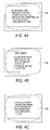
- FIGS. 4A-C illustrate the additional information 128 available for the DTC of FIG. 3A according to an embodiment of the invention.
- the additional information 128 can be provided at various levels of reported fixes, such as top reported fixes, frequently reported fixes and other reported fixes. Top reported fixes can be the more likely to be the solution while frequently reported fixes can be as likely as a solution and also reported fixes are less likely than other solutions, but worth considering. Other levels of reported fixes are also contemplated by the invention.
- the user can use the arrows on the user interface 106 to navigate the additional information 128 on the display 104 .
- the additional information may be updated via a wired or wireless connection so that the technician will have the benefit for the most up to date information available to efficiently diagnose the issues with the vehicle.
- FIG. 5 illustrates the tool 100 communicating with a remote device 500 having the additional information according to another embodiment of the invention.
- the tool 100 includes the ability to access a remote device via a wired or wireless connection.
- the tool 100 is wirelessly communicating with the remote device 500 that stores the additional information 128 in the event the additional information is not stored locally on the diagnostic tool.
- the database on the diagnostic tool can have information in order to indicate if additional information is available for the retrieved diagnostic data, such as the DTCs, but that the additional information is stored remotely from the diagnostic tool.
- the remote device 500 can be located in the garage that the tool 100 is being used or located in another location such as another building, another part of the city, another city, county, state or country.
- the wireless connection can also be via a distributed network, such as the Internet.
- FIG. 6 illustrates a method 600 to display the indicator 122 according to an embodiment of the invention.
- the method 600 can be stored on a memory of tool 100 in the form of software and executed by the processor.
- the method starts.
- the DTC is retrieved from the vehicle and displayed.
- a search of a vehicle specific database to determine if the DTC has additional information or “code connect” information. However, it is not necessary that it is vehicle specific as it could be based on the DTC itself or other diagnostic data.
- a determination is made if the displayed DTC has additional information available.
- step 612 the “code” indicator is removed from the display, if displayed, and the method proceed to step 618 . In other embodiments, the “code” indicator is not displayed. If yes 614 , then at step 616 , the “code” indicator is shown on the display 104 . At step 618 , wait for a key press by the user. At step 620 , a determination is made on whether the “code connect” key is pressed (only if additional information is available). If yes 621 , then at step 622 , show additional information 128 on the display and then return to step 620 . If no 623 , then at step 624 , determine if the “back/enter” key was pressed.
- step 626 If yes 625 , then exit displaying the DTCs at step 626 . If no 627 , then at step 628 determine if the “up/down” arrow key was pressed. If yes 630 , then at step 632 scroll to the next or previous DTC data and return to step 604 to see if other DTC has additional information available. If no 634 , then return to step 604 .
- FIG. 7 illustrates method 700 to display an indicator 122 at a freeze frame menu according to an embodiment of the invention.
- Method 700 starts at step 702 .
- the display displays the freeze frame menu.
- search a vehicle specific database to determine if the highlighted freeze frame menu item has additional information or “code connect” information available.
- step 720 determine if the “code connect” key was pressed (only if additional information is available) by the user. If yes 722 , then at step 724 , show additional information 128 on the display 104 and proceed to step 726 and wait for a key press at step 726 and return to step 720 . If no 728 , then at step 730 determine if the “back/enter” key was pressed. If yes 732 , then exit freeze frame menu at step 734 . If no 736 , then at step 738 determine if the “up/down” arrow key was pressed. If yes 740 , then at step 742 scroll to next or previous freeze frame menu item and proceed to step 704 . If no 744 , then return to step 704 .
- FIG. 8 illustrates method 800 to display an indicator 122 at a freeze frame data item according to an embodiment of the invention.
- Method 800 starts at step 802 .
- the display displays the freeze frame data items.
- search a vehicle specific database to determine if the DTC associated with the freeze frame data items has additional information or “code connect” information available.
- step 818 wait for the user to press a key.
- step 820 determine if the “code connect” key was pressed (only if additional information is available) by the user. If yes 822 , then at step 824 , show additional information 128 on the display 104 and proceed to step 826 and wait for a key press at step 826 and return to step 820 . If no 828 , then at step 830 determine if the “back/enter” key was pressed. If yes 832 , then exit displaying freeze frame data items at step 834 . If no 836 , then at step 838 determine if the “up/down” arrow key was pressed. If yes 840 , then at step 842 scroll freeze frame data item list and return to step 804 . If no 844 , then return to step 804 .
- examples of various embodiments of the invention include indicating that additional information is available based on a retrieved DTC, the additional information could also be associated with any retrieved diagnostic information from the vehicle.
- diagnostic information of a throttle or a sensor.
- the diagnostic tool can automatically determining if additional diagnostic information is available and automatically displays the additional diagnostic information without further interaction by the technician.
Abstract
Description
Claims (26)
Priority Applications (3)
| Application Number | Priority Date | Filing Date | Title |
|---|---|---|---|
| US12/986,559 US8788137B2 (en) | 2010-03-31 | 2011-01-07 | Code connect information access |
| US13/195,386 US8600610B2 (en) | 2010-03-31 | 2011-08-01 | Method and apparatus for identifying related fix information and parts number |
| US14/095,482 US9292977B2 (en) | 2010-03-31 | 2013-12-03 | Method and apparatus for identifying related fix information and parts number |
Applications Claiming Priority (2)
| Application Number | Priority Date | Filing Date | Title |
|---|---|---|---|
| US31960210P | 2010-03-31 | 2010-03-31 | |
| US12/986,559 US8788137B2 (en) | 2010-03-31 | 2011-01-07 | Code connect information access |
Related Child Applications (1)
| Application Number | Title | Priority Date | Filing Date |
|---|---|---|---|
| US13/195,386 Continuation-In-Part US8600610B2 (en) | 2010-03-31 | 2011-08-01 | Method and apparatus for identifying related fix information and parts number |
Publications (2)
| Publication Number | Publication Date |
|---|---|
| US20110246018A1 US20110246018A1 (en) | 2011-10-06 |
| US8788137B2 true US8788137B2 (en) | 2014-07-22 |
Family
ID=44710598
Family Applications (1)
| Application Number | Title | Priority Date | Filing Date |
|---|---|---|---|
| US12/986,559 Expired - Fee Related US8788137B2 (en) | 2010-03-31 | 2011-01-07 | Code connect information access |
Country Status (1)
| Country | Link |
|---|---|
| US (1) | US8788137B2 (en) |
Cited By (4)
| Publication number | Priority date | Publication date | Assignee | Title |
|---|---|---|---|---|
| USD764329S1 (en) * | 2015-04-09 | 2016-08-23 | Fisher-Rosemount Systems, Inc. | Plug for and a handheld maintenance tool |
| CN107492159A (en) * | 2016-12-23 | 2017-12-19 | 宝沃汽车(中国)有限公司 | The data display method and system of freeze frame |
| CN107545615A (en) * | 2016-06-23 | 2018-01-05 | 本田技研工业株式会社 | Vehicle diagnosing system, Vehicular diagnostic method and diagnostic device |
| US11367033B2 (en) | 2011-06-30 | 2022-06-21 | Xrs Corporation | Fleet vehicle management systems and methods |
Families Citing this family (11)
| Publication number | Priority date | Publication date | Assignee | Title |
|---|---|---|---|---|
| US8909416B2 (en) | 2008-04-14 | 2014-12-09 | Innova Electronics, Inc. | Handheld scan tool with fixed solution capability |
| SE536393C2 (en) * | 2012-01-13 | 2013-10-08 | Scania Cv Ab | System and method for providing diagnostic error information on the basis of a plurality of error codes |
| SE536394C2 (en) * | 2012-01-13 | 2013-10-08 | Scania Cv Ab | System and method for providing diagnostic error information based on content from two databases |
| US8977423B2 (en) | 2012-05-23 | 2015-03-10 | Snap-On Incorporated | Methods and systems for providing vehicle repair information |
| US9858731B2 (en) * | 2013-03-15 | 2018-01-02 | Bosch Automotive Service Solutions Inc. | Graphical user interface with vehicle scanned function |
| US9297721B2 (en) * | 2013-03-15 | 2016-03-29 | Bosch Automotive Service Solutions Inc. | Auto ID and fingerprint system and method thereof |
| TWM522269U (en) * | 2016-01-14 | 2016-05-21 | Autoland Scientech Co Ltd | Vehicle choke diagnostic device |
| US11093906B2 (en) | 2016-03-09 | 2021-08-17 | Autozone Parts, Inc. | Systems and apparatuses facilitating a do-it-yourself experience-based repair solution |
| US10152836B2 (en) | 2016-04-19 | 2018-12-11 | Mitchell International, Inc. | Systems and methods for use of diagnostic scan tool in automotive collision repair |
| US10421440B2 (en) * | 2017-01-18 | 2019-09-24 | Snap-On Incorporated | Systems and methods of configuring vehicle service tools associated with display device based on operating condition of vehicle |
| US11062534B2 (en) | 2018-11-28 | 2021-07-13 | Repairify, Inc. | Remote automotive diagnostics |
Citations (27)
| Publication number | Priority date | Publication date | Assignee | Title |
|---|---|---|---|---|
| US4757463A (en) | 1986-06-02 | 1988-07-12 | International Business Machines Corp. | Fault isolation for vehicle using a multifunction test probe |
| US20020007237A1 (en) * | 2000-06-14 | 2002-01-17 | Phung Tam A. | Method and system for the diagnosis of vehicles |
| US20020077779A1 (en) | 2000-10-17 | 2002-06-20 | Spx Corporation | Apparatus and method for displaying diagnostic values |
| US20030060953A1 (en) | 2001-09-21 | 2003-03-27 | Innova Electronics Corporation | Method and system for computer network implemented vehicle diagnostics |
| US20050065678A1 (en) | 2000-08-18 | 2005-03-24 | Snap-On Technologies, Inc. | Enterprise resource planning system with integrated vehicle diagnostic and information system |
| US20060047617A1 (en) | 2004-08-31 | 2006-03-02 | Microsoft Corporation | Method and apparatus for analysis and decomposition of classifier data anomalies |
| US20060123692A1 (en) | 2004-12-14 | 2006-06-15 | Snap-On Incorporated | Dynamic information method and system |
| US20070050105A1 (en) | 2005-08-31 | 2007-03-01 | Spx Corporation | Remote diagnostic data collections for automotive scan tools |
| US20070088465A1 (en) | 2004-11-01 | 2007-04-19 | Heffington Mark F | Programmable automotive computer method and apparatus with accelerometer input |
| US20080140281A1 (en) | 2006-10-25 | 2008-06-12 | Idsc Holdings, Llc | Automatic system and method for vehicle diagnostic data retrieval using multiple data sources |
| EP1953617A2 (en) | 2007-01-26 | 2008-08-06 | Denso Corporation | Vehicle diagnosis system |
| US20080249681A1 (en) * | 2007-04-04 | 2008-10-09 | Spx Corporation | Diagnostic tool with advanced diagnostic capabilities |
| US20080270075A1 (en) * | 2007-04-27 | 2008-10-30 | Spx Corporation | User configurable scan tool |
| US20090271062A1 (en) | 2008-04-25 | 2009-10-29 | Gm Global Technology Operations, Inc. | Control system and method for filtering dependent diagnostic trouble codes |
| US20090276115A1 (en) * | 2005-06-30 | 2009-11-05 | Chen Ieon C | Handheld Automotive Diagnostic Tool with VIN Decoder and Communication System |
| US20100106359A1 (en) | 2006-06-14 | 2010-04-29 | Underdal Olav M | Vehicle State Tracking Method and Apparatus for Diagnostic Testing |
| US20100138701A1 (en) * | 2008-12-03 | 2010-06-03 | Snap-On Incorporated | Method and System for Retrieving Diagnostic Information |
| US20100174446A1 (en) * | 2007-06-28 | 2010-07-08 | Keith Andreasen | Automotive diagnostic process |
| US20100205450A1 (en) * | 2009-02-09 | 2010-08-12 | Sarnacke James G | Vehicle diagnostic tool with copy protection and automatic identification of vehicle ecus and fault display |
| US20100256861A1 (en) | 2009-04-07 | 2010-10-07 | Ford Global Technologies, Llc | System and method for performing vehicle diagnostics |
| US20100256864A1 (en) | 2000-06-12 | 2010-10-07 | I/O Controls Corporation | System and method for facilitating diagnosis and maintenance of a mobile conveyance |
| US20100293081A1 (en) * | 2008-01-05 | 2010-11-18 | Jun Liu | Device and method for reading, registering and analyzing data of automobile ECU |
| US20110071720A1 (en) | 2009-09-21 | 2011-03-24 | Ford Global Technologies, Llc | Methods and systems for monitoring the condition of vehicle components from a nomadic wireless device or computer |
| US7962271B1 (en) | 2006-06-08 | 2011-06-14 | Thompson Bernie C | Vehicle diagnostic tool providing information on the operating condition of a power plant utilizing voltage data |
| US7970722B1 (en) | 1999-11-08 | 2011-06-28 | Aloft Media, Llc | System, method and computer program product for a collaborative decision platform |
| US20110288954A1 (en) | 2010-03-31 | 2011-11-24 | Spx Corporation | Method and Apparatus for Identifying Related Fix Information and Parts Number |
| US20120044086A1 (en) | 2010-08-18 | 2012-02-23 | Snap-On Incorporated | System and method for displaying input data on a remote display device |
-
2011
- 2011-01-07 US US12/986,559 patent/US8788137B2/en not_active Expired - Fee Related
Patent Citations (27)
| Publication number | Priority date | Publication date | Assignee | Title |
|---|---|---|---|---|
| US4757463A (en) | 1986-06-02 | 1988-07-12 | International Business Machines Corp. | Fault isolation for vehicle using a multifunction test probe |
| US7970722B1 (en) | 1999-11-08 | 2011-06-28 | Aloft Media, Llc | System, method and computer program product for a collaborative decision platform |
| US20100256864A1 (en) | 2000-06-12 | 2010-10-07 | I/O Controls Corporation | System and method for facilitating diagnosis and maintenance of a mobile conveyance |
| US20020007237A1 (en) * | 2000-06-14 | 2002-01-17 | Phung Tam A. | Method and system for the diagnosis of vehicles |
| US20050065678A1 (en) | 2000-08-18 | 2005-03-24 | Snap-On Technologies, Inc. | Enterprise resource planning system with integrated vehicle diagnostic and information system |
| US20020077779A1 (en) | 2000-10-17 | 2002-06-20 | Spx Corporation | Apparatus and method for displaying diagnostic values |
| US20030060953A1 (en) | 2001-09-21 | 2003-03-27 | Innova Electronics Corporation | Method and system for computer network implemented vehicle diagnostics |
| US20060047617A1 (en) | 2004-08-31 | 2006-03-02 | Microsoft Corporation | Method and apparatus for analysis and decomposition of classifier data anomalies |
| US20070088465A1 (en) | 2004-11-01 | 2007-04-19 | Heffington Mark F | Programmable automotive computer method and apparatus with accelerometer input |
| US20060123692A1 (en) | 2004-12-14 | 2006-06-15 | Snap-On Incorporated | Dynamic information method and system |
| US20090276115A1 (en) * | 2005-06-30 | 2009-11-05 | Chen Ieon C | Handheld Automotive Diagnostic Tool with VIN Decoder and Communication System |
| US20070050105A1 (en) | 2005-08-31 | 2007-03-01 | Spx Corporation | Remote diagnostic data collections for automotive scan tools |
| US7962271B1 (en) | 2006-06-08 | 2011-06-14 | Thompson Bernie C | Vehicle diagnostic tool providing information on the operating condition of a power plant utilizing voltage data |
| US20100106359A1 (en) | 2006-06-14 | 2010-04-29 | Underdal Olav M | Vehicle State Tracking Method and Apparatus for Diagnostic Testing |
| US20080140281A1 (en) | 2006-10-25 | 2008-06-12 | Idsc Holdings, Llc | Automatic system and method for vehicle diagnostic data retrieval using multiple data sources |
| EP1953617A2 (en) | 2007-01-26 | 2008-08-06 | Denso Corporation | Vehicle diagnosis system |
| US20080249681A1 (en) * | 2007-04-04 | 2008-10-09 | Spx Corporation | Diagnostic tool with advanced diagnostic capabilities |
| US20080270075A1 (en) * | 2007-04-27 | 2008-10-30 | Spx Corporation | User configurable scan tool |
| US20100174446A1 (en) * | 2007-06-28 | 2010-07-08 | Keith Andreasen | Automotive diagnostic process |
| US20100293081A1 (en) * | 2008-01-05 | 2010-11-18 | Jun Liu | Device and method for reading, registering and analyzing data of automobile ECU |
| US20090271062A1 (en) | 2008-04-25 | 2009-10-29 | Gm Global Technology Operations, Inc. | Control system and method for filtering dependent diagnostic trouble codes |
| US20100138701A1 (en) * | 2008-12-03 | 2010-06-03 | Snap-On Incorporated | Method and System for Retrieving Diagnostic Information |
| US20100205450A1 (en) * | 2009-02-09 | 2010-08-12 | Sarnacke James G | Vehicle diagnostic tool with copy protection and automatic identification of vehicle ecus and fault display |
| US20100256861A1 (en) | 2009-04-07 | 2010-10-07 | Ford Global Technologies, Llc | System and method for performing vehicle diagnostics |
| US20110071720A1 (en) | 2009-09-21 | 2011-03-24 | Ford Global Technologies, Llc | Methods and systems for monitoring the condition of vehicle components from a nomadic wireless device or computer |
| US20110288954A1 (en) | 2010-03-31 | 2011-11-24 | Spx Corporation | Method and Apparatus for Identifying Related Fix Information and Parts Number |
| US20120044086A1 (en) | 2010-08-18 | 2012-02-23 | Snap-On Incorporated | System and method for displaying input data on a remote display device |
Non-Patent Citations (3)
| Title |
|---|
| International Search Report and Written Opinion for PCT/US12/12341, mailed Sep. 28, 2012. |
| Search report dated Dec. 3, 2013 for PCT/US2013/057920 filed Sep. 4, 2013. |
| Search Report for European Patent Application No. 11160597.8; dated Aug. 5, 2011. |
Cited By (9)
| Publication number | Priority date | Publication date | Assignee | Title |
|---|---|---|---|---|
| US11367033B2 (en) | 2011-06-30 | 2022-06-21 | Xrs Corporation | Fleet vehicle management systems and methods |
| USD764329S1 (en) * | 2015-04-09 | 2016-08-23 | Fisher-Rosemount Systems, Inc. | Plug for and a handheld maintenance tool |
| USD790997S1 (en) | 2015-04-09 | 2017-07-04 | Fisher-Rosemount Systems, Inc. | Handheld maintenance tool |
| USD818857S1 (en) | 2015-04-09 | 2018-05-29 | Fisher-Rosemount Systems, Inc. | Handheld maintenance tool |
| USD856831S1 (en) | 2015-04-09 | 2019-08-20 | Fisher-Rosemount Systems, Inc. | Handheld maintenance tool |
| USD885215S1 (en) | 2015-04-09 | 2020-05-26 | Fisher-Rosemount Systems, Inc. | Handheld maintenance tool |
| USD950406S1 (en) | 2015-04-09 | 2022-05-03 | Fisher-Rosemount Systems, Inc. | Handheld maintenance tool |
| CN107545615A (en) * | 2016-06-23 | 2018-01-05 | 本田技研工业株式会社 | Vehicle diagnosing system, Vehicular diagnostic method and diagnostic device |
| CN107492159A (en) * | 2016-12-23 | 2017-12-19 | 宝沃汽车(中国)有限公司 | The data display method and system of freeze frame |
Also Published As
| Publication number | Publication date |
|---|---|
| US20110246018A1 (en) | 2011-10-06 |
Similar Documents
| Publication | Publication Date | Title |
|---|---|---|
| US8788137B2 (en) | Code connect information access | |
| US9292977B2 (en) | Method and apparatus for identifying related fix information and parts number | |
| US9030312B2 (en) | Diagnostic tool with global positioning system and alerts | |
| US7979178B2 (en) | Method of flash programming scan tools and pass thru devices over wireless communications | |
| US9418490B2 (en) | Data display with continuous buffer | |
| US20140075356A1 (en) | Diagnostic Hub | |
| US9208627B2 (en) | Scan tool with integrated global positioning system | |
| US9299197B2 (en) | Graphical user interface with on board and off-board resources | |
| US8989950B2 (en) | Diagnostic tool with smart camera | |
| US9330465B2 (en) | Augmented reality virtual automotive X-ray having service information | |
| US8473145B2 (en) | Code evaluator tool with urgency indicator | |
| US10242511B2 (en) | Using on-board monitoring (mode 6) misfire tests in data stream and physical addressing | |
| US20080015748A1 (en) | System for monitoring, controlling, and reporting vehicle operation through onboard diagnostic port | |
| US20080082221A1 (en) | System for monitoring, controlling, and reporting vehicle operation through onboard diagnostic port | |
| US8041476B2 (en) | Error message details for debug available to end user | |
| US20180190043A1 (en) | Mileage Tracking Provisioning | |
| EP2372378A1 (en) | Diagnostic tool for vehicles with a display for additional information | |
| US7328093B1 (en) | Combination scan tool and inspection tool |
Legal Events
| Date | Code | Title | Description |
|---|---|---|---|
| AS | Assignment |
Owner name: SPX CORPORATION, NORTH CAROLINA Free format text: ASSIGNMENT OF ASSIGNORS INTEREST;ASSIGNORS:BERTOSA, THOMAS;ROBERTS, BOB;GESSNER, MICHAEL;AND OTHERS;REEL/FRAME:025734/0028 Effective date: 20110105 |
|
| AS | Assignment |
Owner name: BOSCH AUTOMOTIVE SERVICE SOLUTIONS LLC, MICHIGAN Free format text: CHANGE OF NAME;ASSIGNOR:SERVICE SOLUTIONS U.S. LLC;REEL/FRAME:033123/0870 Effective date: 20130801 Owner name: SERVICE SOLUTIONS U.S. LLC, MICHIGAN Free format text: ASSIGNMENT OF ASSIGNORS INTEREST;ASSIGNOR:SPX CORPORATION;REEL/FRAME:033068/0946 Effective date: 20121130 |
|
| STCF | Information on status: patent grant |
Free format text: PATENTED CASE |
|
| MAFP | Maintenance fee payment |
Free format text: PAYMENT OF MAINTENANCE FEE, 4TH YEAR, LARGE ENTITY (ORIGINAL EVENT CODE: M1551) Year of fee payment: 4 |
|
| FEPP | Fee payment procedure |
Free format text: MAINTENANCE FEE REMINDER MAILED (ORIGINAL EVENT CODE: REM.); ENTITY STATUS OF PATENT OWNER: LARGE ENTITY |
|
| LAPS | Lapse for failure to pay maintenance fees |
Free format text: PATENT EXPIRED FOR FAILURE TO PAY MAINTENANCE FEES (ORIGINAL EVENT CODE: EXP.); ENTITY STATUS OF PATENT OWNER: LARGE ENTITY |
|
| STCH | Information on status: patent discontinuation |
Free format text: PATENT EXPIRED DUE TO NONPAYMENT OF MAINTENANCE FEES UNDER 37 CFR 1.362 |
|
| FP | Lapsed due to failure to pay maintenance fee |
Effective date: 20220722 |