US8777787B2 - Sport ball - Google Patents
Sport ball Download PDFInfo
- Publication number
- US8777787B2 US8777787B2 US13/451,206 US201213451206A US8777787B2 US 8777787 B2 US8777787 B2 US 8777787B2 US 201213451206 A US201213451206 A US 201213451206A US 8777787 B2 US8777787 B2 US 8777787B2
- Authority
- US
- United States
- Prior art keywords
- casing
- bladder
- sport ball
- seams
- ball
- Prior art date
- Legal status (The legal status is an assumption and is not a legal conclusion. Google has not performed a legal analysis and makes no representation as to the accuracy of the status listed.)
- Active
Links
- 239000006261 foam material Substances 0.000 claims abstract description 37
- 229920000642 polymer Polymers 0.000 claims abstract description 13
- 239000004753 textile Substances 0.000 claims description 21
- 239000006260 foam Substances 0.000 claims description 19
- 239000000463 material Substances 0.000 claims description 19
- 238000009966 trimming Methods 0.000 claims description 8
- 239000000853 adhesive Substances 0.000 claims description 7
- 230000001070 adhesive effect Effects 0.000 claims description 7
- 238000007373 indentation Methods 0.000 claims description 7
- 239000002861 polymer material Substances 0.000 claims description 5
- 229920001169 thermoplastic Polymers 0.000 claims description 5
- 239000013536 elastomeric material Substances 0.000 claims 4
- 238000004519 manufacturing process Methods 0.000 abstract description 7
- 239000010410 layer Substances 0.000 description 83
- 238000010276 construction Methods 0.000 description 14
- 238000000034 method Methods 0.000 description 14
- 239000012790 adhesive layer Substances 0.000 description 7
- 229920001971 elastomer Polymers 0.000 description 7
- 239000005060 rubber Substances 0.000 description 7
- 230000008569 process Effects 0.000 description 6
- 230000015572 biosynthetic process Effects 0.000 description 5
- 230000003014 reinforcing effect Effects 0.000 description 5
- 238000002844 melting Methods 0.000 description 4
- 230000008018 melting Effects 0.000 description 4
- 238000005520 cutting process Methods 0.000 description 3
- 239000004816 latex Substances 0.000 description 3
- 229920000126 latex Polymers 0.000 description 3
- 239000007788 liquid Substances 0.000 description 3
- 229920002635 polyurethane Polymers 0.000 description 3
- 239000004814 polyurethane Substances 0.000 description 3
- OKTJSMMVPCPJKN-UHFFFAOYSA-N Carbon Chemical compound [C] OKTJSMMVPCPJKN-UHFFFAOYSA-N 0.000 description 2
- 229910052799 carbon Inorganic materials 0.000 description 2
- 238000009826 distribution Methods 0.000 description 2
- 239000012530 fluid Substances 0.000 description 2
- 238000007429 general method Methods 0.000 description 2
- 230000008570 general process Effects 0.000 description 2
- 238000010438 heat treatment Methods 0.000 description 2
- 238000005304 joining Methods 0.000 description 2
- 239000012815 thermoplastic material Substances 0.000 description 2
- 238000004026 adhesive bonding Methods 0.000 description 1
- 238000005530 etching Methods 0.000 description 1
- 238000000227 grinding Methods 0.000 description 1
- 230000001939 inductive effect Effects 0.000 description 1
- 238000002347 injection Methods 0.000 description 1
- 239000007924 injection Substances 0.000 description 1
- 239000010985 leather Substances 0.000 description 1
- 239000000155 melt Substances 0.000 description 1
- 238000012986 modification Methods 0.000 description 1
- 230000004048 modification Effects 0.000 description 1
- 239000012768 molten material Substances 0.000 description 1
- 239000004800 polyvinyl chloride Substances 0.000 description 1
- 229920000915 polyvinyl chloride Polymers 0.000 description 1
- 239000013589 supplement Substances 0.000 description 1
- 229920001187 thermosetting polymer Polymers 0.000 description 1
- 239000004416 thermosoftening plastic Substances 0.000 description 1
Images


Classifications
-
- A—HUMAN NECESSITIES
- A63—SPORTS; GAMES; AMUSEMENTS
- A63B—APPARATUS FOR PHYSICAL TRAINING, GYMNASTICS, SWIMMING, CLIMBING, OR FENCING; BALL GAMES; TRAINING EQUIPMENT
- A63B41/00—Hollow inflatable balls
- A63B41/10—Bladder and cover united
-
- A—HUMAN NECESSITIES
- A63—SPORTS; GAMES; AMUSEMENTS
- A63B—APPARATUS FOR PHYSICAL TRAINING, GYMNASTICS, SWIMMING, CLIMBING, OR FENCING; BALL GAMES; TRAINING EQUIPMENT
- A63B41/00—Hollow inflatable balls
- A63B41/08—Ball covers; Closures therefor
- A63B41/085—Closures
-
- A—HUMAN NECESSITIES
- A63—SPORTS; GAMES; AMUSEMENTS
- A63B—APPARATUS FOR PHYSICAL TRAINING, GYMNASTICS, SWIMMING, CLIMBING, OR FENCING; BALL GAMES; TRAINING EQUIPMENT
- A63B45/00—Apparatus or methods for manufacturing balls
-
- A—HUMAN NECESSITIES
- A63—SPORTS; GAMES; AMUSEMENTS
- A63B—APPARATUS FOR PHYSICAL TRAINING, GYMNASTICS, SWIMMING, CLIMBING, OR FENCING; BALL GAMES; TRAINING EQUIPMENT
- A63B41/00—Hollow inflatable balls
- A63B41/08—Ball covers; Closures therefor
-
- Y—GENERAL TAGGING OF NEW TECHNOLOGICAL DEVELOPMENTS; GENERAL TAGGING OF CROSS-SECTIONAL TECHNOLOGIES SPANNING OVER SEVERAL SECTIONS OF THE IPC; TECHNICAL SUBJECTS COVERED BY FORMER USPC CROSS-REFERENCE ART COLLECTIONS [XRACs] AND DIGESTS
- Y10—TECHNICAL SUBJECTS COVERED BY FORMER USPC
- Y10T—TECHNICAL SUBJECTS COVERED BY FORMER US CLASSIFICATION
- Y10T156/00—Adhesive bonding and miscellaneous chemical manufacture
- Y10T156/10—Methods of surface bonding and/or assembly therefor
- Y10T156/1002—Methods of surface bonding and/or assembly therefor with permanent bending or reshaping or surface deformation of self sustaining lamina
- Y10T156/1036—Bending of one piece blank and joining edges to form article
-
- Y—GENERAL TAGGING OF NEW TECHNOLOGICAL DEVELOPMENTS; GENERAL TAGGING OF CROSS-SECTIONAL TECHNOLOGIES SPANNING OVER SEVERAL SECTIONS OF THE IPC; TECHNICAL SUBJECTS COVERED BY FORMER USPC CROSS-REFERENCE ART COLLECTIONS [XRACs] AND DIGESTS
- Y10—TECHNICAL SUBJECTS COVERED BY FORMER USPC
- Y10T—TECHNICAL SUBJECTS COVERED BY FORMER US CLASSIFICATION
- Y10T156/00—Adhesive bonding and miscellaneous chemical manufacture
- Y10T156/10—Methods of surface bonding and/or assembly therefor
- Y10T156/1052—Methods of surface bonding and/or assembly therefor with cutting, punching, tearing or severing
- Y10T156/108—Flash, trim or excess removal
-
- Y—GENERAL TAGGING OF NEW TECHNOLOGICAL DEVELOPMENTS; GENERAL TAGGING OF CROSS-SECTIONAL TECHNOLOGIES SPANNING OVER SEVERAL SECTIONS OF THE IPC; TECHNICAL SUBJECTS COVERED BY FORMER USPC CROSS-REFERENCE ART COLLECTIONS [XRACs] AND DIGESTS
- Y10—TECHNICAL SUBJECTS COVERED BY FORMER USPC
- Y10T—TECHNICAL SUBJECTS COVERED BY FORMER US CLASSIFICATION
- Y10T83/00—Cutting
- Y10T83/04—Processes
- Y10T83/06—Blanking
Definitions
- a variety of inflatable sport balls such as a soccer ball, conventionally exhibit a layered structure that includes a casing, an intermediate layer, and an inflatable bladder.
- the casing forms an exterior layer of the sport ball and is generally formed from a plurality of durable, wear-resistant panels joined together along abutting edges (e.g., with stitching or adhesives).
- panel configurations may vary significantly, the casing of a traditional soccer ball includes thirty-two panels, twelve of which have a pentagonal shape and twenty of which have a hexagonal shape.
- the intermediate layer forms a middle layer of the sport ball and is positioned between the bladder and the casing.
- the bladder which has an inflatable configuration, is located within the intermediate layer to provide an inner layer of the sport ball.
- the bladder In order to facilitate inflation (i.e., with air), the bladder generally includes a valved opening that extends through each of the intermediate layer and casing, thereby being accessible from an exterior of the sport ball.
- the intermediate layer of a conventional sport ball may have a variety of configurations.
- a conventional intermediate layer may be formed from multiple material layers that include (a) a compressible foam layer located adjacent to the casing to impart a softened feel to the sport ball, (b) a rubber layer that imparts energy return, (c) a textile layer with a limited degree of stretch in order to restrict expansion of the bladder, and (d) multiple adhesive layers that extend between and join the foam, rubber, and textile layers.
- the intermediate layers of some sport balls incorporate each of these layers, one or more of these layers may be absent.
- the configuration of the individual layers may vary significantly.
- the textile layer may be formed from (a) a plurality of generally flat or planar textile elements that are stitched together, (b) a thread, yarn, or filament that is repeatedly wound around the bladder in various directions to form a mesh, or (c) a plurality of generally flat or planar textile strips that are impregnated with latex and placed in an overlapping configuration around the bladder.
- the various layers of the intermediate layer may also be bonded, joined, or otherwise incorporated into the casing as a backing material.
- a sport ball may include a casing, an intermediate layer, and a bladder.
- the casing forms at least a portion of an exterior surface of the ball.
- the intermediate layer is at least partially formed from a foam material located adjacent to the casing and within the casing.
- the bladder has an inflatable configuration and is located adjacent to the intermediate layer and within the intermediate layer.
- the foam material of the intermediate layer may be bonded to each of the casing and the bladder.
- a bladder may be located in a mold and a polymer foam material may be injected into the mold and onto a surface of the bladder.
- panel elements may also be located within the mold, and the polymer foam material may be injected into an area between the bladder and the panel elements.
- edges of the panel elements may be heatbonded to each other to join the panel elements and form a casing of the sport ball.
- FIG. 1 is a perspective view of a sport ball.
- FIG. 2 is another perspective view of the sport ball.
- FIG. 3 is a partial cross-sectional view of the sport ball, as defined by section line 3 - 3 in FIG. 2 .
- FIGS. 4A-4F are partial cross-sectional views corresponding with FIG. 3 and depicting further configurations of the sport ball.
- FIG. 5 is a perspective view of a blank for forming a panel of the sport ball.
- FIG. 6 is another perspective view of the blank.
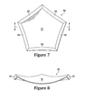
- FIG. 7 is a plan view of the blank.
- FIG. 8 is a cross-sectional view of the blank, as defined by section line 8 - 8 in FIG. 7 .
- FIG. 9 is a perspective view of a first mold that may be utilized in constructing the sport ball.
- FIG. 10 is a cross-sectional view of the first mold, as defined by section line 10 - 10 in FIG. 9 .
- FIGS. 11A-11E are cross-sectional views corresponding with FIG. 10 and depicting a construction method for the sport ball.
- FIG. 12 is a perspective view of the sport ball following the construction method.
- FIG. 13 is a partial cross-sectional view of the sport ball following the construction method, as defined by section line 13 - 13 in FIG. 12 .
- FIG. 14 is a perspective view of a die that may be utilized in forming seams of the sport ball.
- FIG. 15 is a cross-sectional view of the die, as defined by section line 15 - 15 in FIG. 14 .
- FIGS. 16A-16D are cross-sectional views corresponding with FIG. 15 and depicting a seam formation method for the sport ball.
- FIG. 17 is a cross-sectional view that corresponds with FIG. 15 and depicts another configuration of the die.
- FIG. 18 is a perspective view of a second mold that may be utilized in constructing the sport ball.
- FIG. 19 is a cross-sectional view of the second mold, as defined by section line 19 - 19 in FIG. 18 .
- FIGS. 20A-20C are cross-sectional views corresponding with FIG. 19 and depicting a construction method for the sport ball.
- FIG. 21 is a perspective view of a third mold that may be utilized in constructing the sport ball.
- FIG. 22 is a cross-sectional view of the third mold, as defined by section line 22 - 22 in FIG. 21 .
- FIGS. 23A and 23B are cross-sectional views corresponding with FIG. 22 and depicting a construction method for the sport ball.
- FIGS. 1 and 2 A sport ball 10 with the configuration of a soccer ball is depicted in FIGS. 1 and 2 .
- Ball 10 has a layered structure that includes a casing 20 , an intermediate layer 30 , and an inflatable or inflated bladder 40 , each of which are depicted in FIGS. 2 and 3 .
- Casing 20 forms an exterior of ball 10 and is generally formed from various panels 21 that are joined along abutting sides or edges to form a plurality of seams 22 .
- Each of panels 21 are depicted as having the shapes of equilateral pentagons.
- panels 21 may be formed from a combination of pentagonal and hexagonal shapes, panels 21 may have non-equilateral shapes, panels 21 may have concave or convex edges, and selected panels 21 may be formed integral with adjacent panels 21 to form bridged panels that reduce the number of seams 22 , for example.
- Panels 21 may also have a variety of other shapes (e.g., triangular, square, rectangular, hexagonal, trapezoidal, round, oval) that combine in a tessellation-type manner to form casing 20 , and panels 21 may also exhibit non-regular or non-geometrical shapes.
- casing 20 may have a seamless structure (i.e., a configuration where seams 22 are absent).
- each of panels 21 may have a layered configuration that combines two or more materials.
- an exterior portion of each panel 21 may be formed from polyurethane, and an interior portion of each panel 21 may be formed from a textile element 23 , as depicted in FIG. 4A . That is, textile element 23 may be bonded to the polyurethane and positioned adjacent to intermediate layer 30 .
- non-textile materials or reinforcing structures may also be incorporated into casing 20 . Accordingly, the configuration of casing 20 may vary significantly to include a variety of configurations and materials.
- An advantage of casing 20 relates to the manner in which panels 21 are joined to form seams 22 .
- the panels of conventional sport balls may be joined with stitching (e.g., hand or machine stitching).
- stitching e.g., hand or machine stitching
- panels 21 may be joined through stitching in some configurations, a heatbonding method is utilized in ball 10 to join panels 21 and form seams 22 .
- panels 21 may be formed from a thermoplastic material, and edges of panels 21 may be heated and bonded to each other to form seams 22 .
- An advantage of heatbonding when forming seams 22 relates to the overall mass of ball 10 . Whereas approximately ten to fifteen percent of the mass of a conventional sport ball may be from the seams between panels, heatbonding panels 21 may reduce the mass at seams 22 .
- the mass that would otherwise be imparted by the stitched seams may be utilized for other structural elements that enhance the performance properties (e.g., energy return, sphericity, mass distribution, durability, aerodynamics) of ball 10 .
- Intermediate layer 30 forms a middle layer of ball 10 that is positioned between casing 20 and bladder 40 .
- conventional intermediate layers are formed from foam, rubber, textiles, and adhesive layers.
- FIGS. 2 and 3 depict intermediate layer 30 as being formed from a polymer foam material. That is, the polymer foam material extends from a surface of casing 20 to a surface of bladder 40 .
- substantially all of intermediate layer 30 may be formed from the polymer foam material, some configurations of intermediate layer 30 may incorporate other elements.
- intermediate layer 30 is depicted as incorporating a textile element 31 in FIG. 4B .
- textile element 31 may extend through a central area of intermediate layer 30
- textile element 31 may also be located adjacent to bladder 40 , as depicted in FIG.
- intermediate layer 30 is depicted as incorporating a reinforcing structure 32 in FIG. 4D
- intermediate layer 30 is depicted as incorporating a pair of different foam layers 33 and 34 in FIG. 4E .
- intermediate layer 30 may be entirely formed from a single polymer foam material, intermediate layer 30 may also incorporate other elements or materials in some configurations of ball 10 .
- a conventional intermediate layer may be formed from multiple material layers that include (a) a compressible foam layer, (b) a rubber layer, (c) a textile layer, and (d) multiple adhesive layers that extend between and join the foam, rubber, and textile layers, as discussed in the Background section above.
- the mass of the adhesive layers may impart approximately twenty-five percent of the total mass of the sport balls. That is, the adhesive layers alone account for twenty-five percent of the total mass of the sport balls.
- the mass that would otherwise be imparted by the adhesive layers may be utilized for other structural elements that enhance the performance properties (e.g., energy return, sphericity, mass distribution, durability, aerodynamics) of ball 10 .
- Bladder 40 has an inflatable configuration and is located within intermediate layer 30 to provide an inner portion of ball 10 . When inflated, bladder 40 exhibits a rounded or generally spherical shape. In order to facilitate inflation, bladder 40 may include a valved opening (not depicted) that extends through intermediate layer 30 and casing 20 , thereby being accessible from an exterior of ball 10 , or bladder 40 may have a valveless structure that is semi-permanently inflated. Bladder 40 may be formed from a rubber or carbon latex material that substantially prevents air or other fluids within bladder 40 from diffusing to the exterior of ball 10 . In addition to rubber and carbon latex, a variety of other elastomeric or otherwise stretchable materials may be utilized for bladder 40 .
- Inflating bladder 40 induces ball 10 to take on a substantially spherical shape. More particularly, fluid pressure from air within bladder 40 causes bladder 40 to expand and place an outward force upon intermediate layer 30 . In turn, intermediate layer 30 places an outward force upon casing 20 .
- intermediate layer 30 may have a limited degree of stretch. That is, intermediate layer 30 may be formed from a foam material that has a limited degree of stretch. Alternately, textile elements 23 and 31 , reinforcing structure 32 , or one or both of foam layers 33 and 34 may exhibit a limited degree of stretch. In any of these configurations, the stretch characteristics of intermediate layer 30 may prevent the expansion of bladder 40 from inducing significant tension in casing 20 .
- intermediate layer 30 may restrain the expansion of bladder 40 , while permitting outward forces to induce a substantially spherical shape in casing 20 , thereby imparting a substantially spherical shape to ball 10 .
- bladder 40 may incorporate a tensile element 41 that restrains the overall expansion of bladder 40 and limits the tension in casing 20 , as depicted in FIG. 4F .
- a variety of construction methods may be utilized for ball 10 .
- a polymer foam material is injected into a space between a panel blank 50 and bladder 40 .
- panel blank 50 is depicted as including a panel area 51 and a flange area 52 .
- Panel area 51 has a pentagonal configuration with a curvature that corresponds with a curvature in casing 20 . Given this configuration, panel area 51 becomes one of panels 21 following the construction method and the formation of seams 22 . Panel 51 is, therefore, a casing element that becomes a portion of casing 20 following the construction method.
- Flange area 52 extends around and outward from panel area 51 and effectively forms a flange that is utilized in joining multiple panel areas 51 together, thereby forming seams 22 .
- panel blank 50 may be formed from any of the materials discussed above for casing 20 .
- Mold 60 that may be utilized in constructing ball 10 is depicted in FIGS. 9 and 10 .
- Mold 60 includes an upper portion with an outer surface 61 that surrounds a central surface 62 .
- Outer surface 61 has an inwardly-curved or otherwise concave configuration that substantially corresponds with a curvature of an exterior of bladder 40 .
- a middle portion of outer surface 61 defines an aperture 63 with a pentagonal shape, and central surface 62 is recessed within aperture 63 .
- central surface 62 has an inwardly-curved or otherwise concave configuration that substantially corresponds with a curvature of an exterior of casing 20 .
- Central surface 62 is spaced downward from outer surface 61 , and a conduit 64 extends upward from a reservoir 65 to join with a periphery of central area 62 .
- one of panel blanks 50 is located within aperture 63 and adjacent to central surface 62 , as depicted in FIG. 11A . More particularly, panel area 51 is positioned to contact central surface 62 and flange area 52 is positioned to extend into conduit 64 . As discussed above, panel area 51 has a curvature that corresponds with a curvature in casing 20 , and central surface 62 substantially corresponds with a curvature of an exterior of casing 20 . Given this configuration, panel area 51 matches and conforms with the inwardly-curved or otherwise concave configuration of central surface 62 .
- bladder 40 is inflated to a generally spherical shape having a diameter that is substantially equal to the diameter of bladder 40 within ball 10 .
- Bladder 40 is then positioned to contact outer surface 61 , as depicted in FIG. 11B .
- outer surface 61 substantially corresponds with a curvature of an exterior of bladder 40 .
- bladder 40 matches and conforms with the inwardly-curved or otherwise concave configuration of outer surface 61 .
- a foam material 66 in an uncured, resinous, or semi-liquid state may be located within reservoir 65 .
- a gap 67 extends between bladder 40 and panel area 51 when (a) bladder 40 is positioned in contact with outer surface 61 and (b) panel blank 50 is positioned in contact with central surface 62 , as depicted in FIG. 11B .
- the distance between bladder 40 and panel area 51 corresponds with the thickness of intermediate layer 30 .
- intermediate layer 30 is formed from a polymer foam material.
- foam material 66 is injected or otherwise located within gap 67 , as depicted in FIG. 11C . More particularly, foam material 66 passes into conduit 64 and flows upward to infiltrate the area between bladder 40 and panel area 51 , thereby filling gap 67 .
- textile element 31 or reinforcing structure 32 may be located within gap 67 prior to introducing foam material 66 .
- foam material 66 may begin curing and bonding with the surfaces of bladder 40 and panel area 51 , thereby forming a portion of intermediate layer 30 .
- the combination of bladder 40 , panel blank 50 , and foam material 66 may then be withdrawn from mold 60 , as depicted in FIG. 11D . Excess foam material 66 may also be removed or cleaned from flange area 52 at this stage of the construction method.
- intermediate layer 30 extends continuously around bladder 30 and under the interface between two adjacent panel blanks 50 .
- flange areas 52 from the adjacent panel blanks 50 abut each other.
- one of seams 22 may be formed. That is, seams 22 are formed in ball 10 by bonding and trimming flange areas 52 . In some configurations of ball 10 , trimming operations may not be utilized, depending upon the height of flange areas 52 .
- a die 70 that may be utilized in forming seams 22 is depicted in FIGS. 14 and 15 .
- Die 70 includes two portions 71 that each define a protrusion 72 .
- a length of each portion 71 corresponds with a length of one of the sides of panels 21 , which is substantially equal to the length of portions of flange areas 52 that abut each other.
- Protrusions 72 extend in a downward direction and along the lengths of portions 71 .
- Each portion 71 also defines a facing surface 73 that faces the other portion 71 . That is, facing surfaces 73 face each other.
- Protrusions 72 are positioned adjacent to facing surfaces 73 .
- FIGS. 16A-16D A method of utilizing die 70 to form seams 22 is depicted in FIGS. 16A-16D .
- portions 71 are located on opposite sides of the abutting flange areas 52 , as depicted in FIG. 16A .
- Portions 71 then (a) compress the abutting flange areas 52 together between facing surfaces 73 , (b) press into ball 10 , and (c) heat the abutting flange areas 52 , as depicted in FIG. 16B .
- the thermoplastic material forming the abutting flange areas 52 melts or otherwise softens to a degree that facilitates bonding between flange areas 52 .
- some conventional sport balls utilize stitching or adhesives to join adjacent panels, flange areas 52 are joined through heatbonding.
- heatbonding is defined as a securing technique between two elements that involves a melting or softening of at least one of the elements such that the materials of the elements are secured to each other when cooled.
- heatbonding may involve the melting or softening of the adjacent flange areas 52 (or other portions of panel blanks 50 ) such that the materials diffuse across a boundary layer between flange areas 52 and are secured together when cooled.
- Heatbonding may also involve the melting or softening of only one flange area 52 such that the molten material extends into crevices or cavities formed by the other flange area 52 , thereby securing the components together when cooled. Accordingly, heatbonding does not generally involve the use of stitching or adhesives. Rather, two elements are directly bonded to each other with heat. In some situations, however, stitching or adhesives may be utilized to supplement the joining of elements through heatbonding.
- die 70 may incorporate heating elements that raise the temperature of portions 71 , thereby conducting heat to flange areas 52 .
- die 70 may emit radio frequency energy (RF energy) that heats flange areas 52 . More particularly, the radio frequency energy may pass between facing surfaces 73 and through flange areas 52 . When irradiated with the radio frequency energy, the temperature of the polymer material forming flange areas 52 increases until melting and softening occurs. Given that flange areas 52 are also compressed between facing surfaces 73 , the increased temperature facilitates the formation of a heatbond between flange areas 52 .
- RF energy radio frequency energy
- portions 71 press into ball 10 at this stage of forming seams 22 .
- protrusions 72 press into ball 10 .
- seams 22 may be formed at a position that corresponds with the surfaces of panel areas 51 (i.e., panels 21 )
- protrusions 72 ensure that seam 22 is recessed into the surface of ball 10 . That is, indentations are formed in ball 10 at seams 22 .
- An advantage of this configuration is that seams 22 are less likely to experience wear as ball 10 rubs or otherwise abrades against the ground or other surfaces or objects. That is, protrusions ensure that seams 22 are recessed relative to a remainder of panels 21 in order to enhance the overall durability of ball 10 .
- portions 71 may retract from ball 10 , as depicted in FIG. 16C . Excess portions of flange areas 52 are then removed to complete the formation of one of panels 21 and seams 22 , as depicted in FIG. 16D .
- a variety of trimming processes may be utilized to remove the excess portions of flange areas 52 .
- the trimming processes may include the use of a cutting apparatus, a grinding wheel, or an etching process.
- die 70 may incorporate cutting edges 74 , as depicted in FIG. 17 , that trim flange areas 52 during the heatbonding process.
- cutting edges 74 may be utilized to protrude through flange areas 52 and effectively trim flange areas 52 as portions 71 (a) compress the abutting flange areas 52 together between facing surfaces 73 , (b) press into ball 10 , and (c) heat the abutting flange areas 52 .
- the general process of bonding flange areas 52 together and removing excess portions of flange areas 52 may be performed at each interface between panel blanks 50 to effectively form panels 21 and seams 22 (i.e., to form casing 20 ), thereby substantially completing the manufacture of ball 10 .
- a mold 80 is depicted as having an upper portion 81 and a lower portion 82 that are separable from each other. Portions 81 and 82 cooperatively define a generally spherical interior cavity 83 with a diameter that is substantially equal to a diameter of ball 10 . Portions 81 and 82 also define various linear indentations 84 that extend outward from cavity 83 and correspond in location with seams 22 of ball 10 .
- various panel blanks 50 are located within cavity 83 such that (a) panel areas 51 are adjacent to a surface of cavity 83 and (b) flange portions 52 extend into indentations 84 , as depicted in FIG. 20A .
- bladder 40 is inflated to a generally spherical shape having a diameter that is substantially equal to the diameter of bladder 40 within ball 10 .
- Bladder 40 is then located within cavity 83 and in a position that is spaced from panel blanks 50 , as depicted in FIG. 20B .
- mold 80 may be opened by separating portions 81 and 82 .
- the combination of intermediate layer 30 , bladder 40 , and panel blanks 50 may then be removed and has the general configuration depicted in FIG. 12 .
- the general method discussed above for forming seams 22 may then be utilized to substantially complete the manufacture of ball 10 .
- a mold 90 may be utilized to construct ball 10 .
- mold 90 is depicted as having an upper portion 91 and a lower portion 92 that are separable from each other. Portions 91 and 92 cooperatively define a generally spherical interior cavity 93 with a diameter that is substantially equal to a diameter of intermediate layer 30 . In contrast with mold 80 , therefore, the diameter of cavity 93 is the diameter of intermediate layer 30 .
- structures corresponding to indentations 84 are absent from mold 90 .
- bladder 40 is inflated to a generally spherical shape having a diameter that is substantially equal to the diameter of bladder 40 within ball 10 .
- Bladder 40 is then located within cavity 93 and in a position that is spaced from a surface of cavity 93 , as depicted in FIG. 23A .
- a foam material in an uncured, resinous, or semi-liquid state which is similar to foam material 66 , is then injected into a gap between bladder 40 and the surface of cavity 93 to form intermediate layer 30 , as depicted in FIG. 23B .
- mold 90 may be opened by separating portions 91 and 92 .
- intermediate layer 30 and bladder 40 may then be removed.
- Panel blanks 50 are then secured to intermediate layer 30 through heatbonding or adhesive bonding, for example, to impart the general configuration depicted in FIG. 12 .
- the general method discussed above for forming seams 22 may then be utilized to substantially complete the manufacture of ball 10 .
- intermediate layer 30 of ball 10 is at least partially formed from a foam material and located adjacent to casing 20 and within casing 20 .
- Bladder 40 is located adjacent to intermediate layer 30 and within intermediate layer 30 .
- the foam material of intermediate layer 30 may be bonded to each of casing 20 and bladder 40 .
- bladder 40 and a casing element e.g., one of panels 21 or one of panel blanks 50 are located within a mold, with at least a portion of a surface of the casing element being spaced from a surface of bladder 40 .
- a polymer foam material is then injected into the mold and between bladder 40 and the casing element.
- the casing elements may include a thermoplastic polymer material, and the casing elements may be heatbonded to each other to form seams 22 .
Abstract
A sport ball may include a casing, an intermediate layer, and a bladder. In manufacturing the sport ball, a panel element of the casing and the bladder may be located in a mold, and a polymer foam material of the intermediate layer may be injected into an area between the bladder and the panel element. In addition, edges of panel element may be heatbonded to each other to join the panel elements and form seams of the casing.
Description
This application is a divisional of prior pending nonprovisional application Ser. No. 12/147,874, filed 27 Jun. 2008, the entire disclosure of which is hereby incorporated by reference.
A variety of inflatable sport balls, such as a soccer ball, conventionally exhibit a layered structure that includes a casing, an intermediate layer, and an inflatable bladder. The casing forms an exterior layer of the sport ball and is generally formed from a plurality of durable, wear-resistant panels joined together along abutting edges (e.g., with stitching or adhesives). Although panel configurations may vary significantly, the casing of a traditional soccer ball includes thirty-two panels, twelve of which have a pentagonal shape and twenty of which have a hexagonal shape. The intermediate layer forms a middle layer of the sport ball and is positioned between the bladder and the casing. The bladder, which has an inflatable configuration, is located within the intermediate layer to provide an inner layer of the sport ball. In order to facilitate inflation (i.e., with air), the bladder generally includes a valved opening that extends through each of the intermediate layer and casing, thereby being accessible from an exterior of the sport ball.
The intermediate layer of a conventional sport ball may have a variety of configurations. As an example, a conventional intermediate layer may be formed from multiple material layers that include (a) a compressible foam layer located adjacent to the casing to impart a softened feel to the sport ball, (b) a rubber layer that imparts energy return, (c) a textile layer with a limited degree of stretch in order to restrict expansion of the bladder, and (d) multiple adhesive layers that extend between and join the foam, rubber, and textile layers. Although the intermediate layers of some sport balls incorporate each of these layers, one or more of these layers may be absent. Moreover, the configuration of the individual layers may vary significantly. For example, the textile layer may be formed from (a) a plurality of generally flat or planar textile elements that are stitched together, (b) a thread, yarn, or filament that is repeatedly wound around the bladder in various directions to form a mesh, or (c) a plurality of generally flat or planar textile strips that are impregnated with latex and placed in an overlapping configuration around the bladder. The various layers of the intermediate layer may also be bonded, joined, or otherwise incorporated into the casing as a backing material.
A sport ball may include a casing, an intermediate layer, and a bladder. The casing forms at least a portion of an exterior surface of the ball. The intermediate layer is at least partially formed from a foam material located adjacent to the casing and within the casing. The bladder has an inflatable configuration and is located adjacent to the intermediate layer and within the intermediate layer. The foam material of the intermediate layer may be bonded to each of the casing and the bladder.
In manufacturing a sport ball, a bladder may be located in a mold and a polymer foam material may be injected into the mold and onto a surface of the bladder. In some configurations, panel elements may also be located within the mold, and the polymer foam material may be injected into an area between the bladder and the panel elements. In addition, edges of the panel elements may be heatbonded to each other to join the panel elements and form a casing of the sport ball.
The advantages and features of novelty characterizing aspects of the invention are pointed out with particularity in the appended claims. To gain an improved understanding of the advantages and features of novelty, however, reference may be made to the following descriptive matter and accompanying figures that describe and illustrate various configurations and concepts related to the invention.
The foregoing Summary and the following Detailed Description will be better understood when read in conjunction with the accompanying figures.
The following discussion and accompanying figures disclose various sport ball configurations and methods of manufacturing the sport balls. Although the sport ball configurations are discussed and depicted in relation to a soccer ball, concepts associated with the configurations and methods may be applied to various types of inflatable sport balls. In addition to soccer balls, therefore, concepts discussed herein may be incorporated into basketballs, footballs (for either American football or rugby), and volleyballs, for example. A variety of non-inflatable sport balls, such as baseballs, softballs, and golf balls, may also incorporate concepts discussed herein.
Sport Ball Structure
A sport ball 10 with the configuration of a soccer ball is depicted in FIGS. 1 and 2 . Ball 10 has a layered structure that includes a casing 20, an intermediate layer 30, and an inflatable or inflated bladder 40, each of which are depicted in FIGS. 2 and 3 . Casing 20 forms an exterior of ball 10 and is generally formed from various panels 21 that are joined along abutting sides or edges to form a plurality of seams 22. Each of panels 21 are depicted as having the shapes of equilateral pentagons. In further configurations of ball 10, however, panels 21 may be formed from a combination of pentagonal and hexagonal shapes, panels 21 may have non-equilateral shapes, panels 21 may have concave or convex edges, and selected panels 21 may be formed integral with adjacent panels 21 to form bridged panels that reduce the number of seams 22, for example. Panels 21 may also have a variety of other shapes (e.g., triangular, square, rectangular, hexagonal, trapezoidal, round, oval) that combine in a tessellation-type manner to form casing 20, and panels 21 may also exhibit non-regular or non-geometrical shapes. In other configurations, casing 20 may have a seamless structure (i.e., a configuration where seams 22 are absent).
The materials selected for casing 20 may be leather, polyurethane, polyvinyl chloride, various other thermoplastic or thermoset materials, or other suitable materials, whether synthetic or natural, that are generally durable and wear-resistant. In some configurations, each of panels 21 may have a layered configuration that combines two or more materials. For example, an exterior portion of each panel 21 may be formed from polyurethane, and an interior portion of each panel 21 may be formed from a textile element 23, as depicted in FIG. 4A . That is, textile element 23 may be bonded to the polyurethane and positioned adjacent to intermediate layer 30. As an alternative to textile element 23, non-textile materials or reinforcing structures may also be incorporated into casing 20. Accordingly, the configuration of casing 20 may vary significantly to include a variety of configurations and materials.
An advantage of casing 20 relates to the manner in which panels 21 are joined to form seams 22. The panels of conventional sport balls may be joined with stitching (e.g., hand or machine stitching). Although panels 21 may be joined through stitching in some configurations, a heatbonding method is utilized in ball 10 to join panels 21 and form seams 22. More particularly, panels 21 may be formed from a thermoplastic material, and edges of panels 21 may be heated and bonded to each other to form seams 22. An advantage of heatbonding when forming seams 22 relates to the overall mass of ball 10. Whereas approximately ten to fifteen percent of the mass of a conventional sport ball may be from the seams between panels, heatbonding panels 21 may reduce the mass at seams 22. By eliminating stitched seams in casing 20, the mass that would otherwise be imparted by the stitched seams may be utilized for other structural elements that enhance the performance properties (e.g., energy return, sphericity, mass distribution, durability, aerodynamics) of ball 10.
An advantage of the configuration of intermediate layer 30 relates to the overall mass of intermediate layer 30. A conventional intermediate layer may be formed from multiple material layers that include (a) a compressible foam layer, (b) a rubber layer, (c) a textile layer, and (d) multiple adhesive layers that extend between and join the foam, rubber, and textile layers, as discussed in the Background section above. In some conventional sport balls, the mass of the adhesive layers may impart approximately twenty-five percent of the total mass of the sport balls. That is, the adhesive layers alone account for twenty-five percent of the total mass of the sport balls. By eliminating the adhesive layers in intermediate layer 30, the mass that would otherwise be imparted by the adhesive layers may be utilized for other structural elements that enhance the performance properties (e.g., energy return, sphericity, mass distribution, durability, aerodynamics) of ball 10.
Inflating bladder 40 induces ball 10 to take on a substantially spherical shape. More particularly, fluid pressure from air within bladder 40 causes bladder 40 to expand and place an outward force upon intermediate layer 30. In turn, intermediate layer 30 places an outward force upon casing 20. In order to limit the expansion of bladder 40 and also limit tension in casing 20, intermediate layer 30 may have a limited degree of stretch. That is, intermediate layer 30 may be formed from a foam material that has a limited degree of stretch. Alternately, textile elements 23 and 31, reinforcing structure 32, or one or both of foam layers 33 and 34 may exhibit a limited degree of stretch. In any of these configurations, the stretch characteristics of intermediate layer 30 may prevent the expansion of bladder 40 from inducing significant tension in casing 20. Accordingly, intermediate layer 30 may restrain the expansion of bladder 40, while permitting outward forces to induce a substantially spherical shape in casing 20, thereby imparting a substantially spherical shape to ball 10. In some configurations, however, bladder 40 may incorporate a tensile element 41 that restrains the overall expansion of bladder 40 and limits the tension in casing 20, as depicted in FIG. 4F .
Construction Method
A variety of construction methods may be utilized for ball 10. As an example of a suitable construction method, a polymer foam material is injected into a space between a panel blank 50 and bladder 40. Referring to FIGS. 5-8 , panel blank 50 is depicted as including a panel area 51 and a flange area 52. Panel area 51 has a pentagonal configuration with a curvature that corresponds with a curvature in casing 20. Given this configuration, panel area 51 becomes one of panels 21 following the construction method and the formation of seams 22. Panel 51 is, therefore, a casing element that becomes a portion of casing 20 following the construction method. Flange area 52 extends around and outward from panel area 51 and effectively forms a flange that is utilized in joining multiple panel areas 51 together, thereby forming seams 22. Given that panel blank 50 forms one of panels 21 and various seams 22, panel blank 50 may be formed from any of the materials discussed above for casing 20.
A mold 60 that may be utilized in constructing ball 10 is depicted in FIGS. 9 and 10 . Mold 60 includes an upper portion with an outer surface 61 that surrounds a central surface 62. Outer surface 61 has an inwardly-curved or otherwise concave configuration that substantially corresponds with a curvature of an exterior of bladder 40. A middle portion of outer surface 61 defines an aperture 63 with a pentagonal shape, and central surface 62 is recessed within aperture 63. Whereas the curvature of outer surface 61 substantially corresponds with the curvature of the exterior of bladder 40, central surface 62 has an inwardly-curved or otherwise concave configuration that substantially corresponds with a curvature of an exterior of casing 20. Central surface 62 is spaced downward from outer surface 61, and a conduit 64 extends upward from a reservoir 65 to join with a periphery of central area 62.
The manner in which mold 60 is utilized in constructing ball 10 will now be discussed with reference to FIGS. 11A-11E . Initially, one of panel blanks 50 is located within aperture 63 and adjacent to central surface 62, as depicted in FIG. 11A . More particularly, panel area 51 is positioned to contact central surface 62 and flange area 52 is positioned to extend into conduit 64. As discussed above, panel area 51 has a curvature that corresponds with a curvature in casing 20, and central surface 62 substantially corresponds with a curvature of an exterior of casing 20. Given this configuration, panel area 51 matches and conforms with the inwardly-curved or otherwise concave configuration of central surface 62.
Once panel blank 50 is properly positioned, bladder 40 is inflated to a generally spherical shape having a diameter that is substantially equal to the diameter of bladder 40 within ball 10. Bladder 40 is then positioned to contact outer surface 61, as depicted in FIG. 11B . As discussed above, outer surface 61 substantially corresponds with a curvature of an exterior of bladder 40. Given this configuration, bladder 40 matches and conforms with the inwardly-curved or otherwise concave configuration of outer surface 61. Additionally, a foam material 66 in an uncured, resinous, or semi-liquid state may be located within reservoir 65.
A gap 67 extends between bladder 40 and panel area 51 when (a) bladder 40 is positioned in contact with outer surface 61 and (b) panel blank 50 is positioned in contact with central surface 62, as depicted in FIG. 11B . In general, the distance between bladder 40 and panel area 51 (i.e., the distance across gap 67) corresponds with the thickness of intermediate layer 30. As discussed above, intermediate layer 30 is formed from a polymer foam material. In order to form intermediate layer 30, therefore, foam material 66 is injected or otherwise located within gap 67, as depicted in FIG. 11C . More particularly, foam material 66 passes into conduit 64 and flows upward to infiltrate the area between bladder 40 and panel area 51, thereby filling gap 67. In configurations of ball 10 where textile element 31 or reinforcing structure 32 are present, textile element 31 or reinforcing structure 32 may be located within gap 67 prior to introducing foam material 66.
Once foam material 66 is located within gap 67, foam material 66 may begin curing and bonding with the surfaces of bladder 40 and panel area 51, thereby forming a portion of intermediate layer 30. The combination of bladder 40, panel blank 50, and foam material 66 may then be withdrawn from mold 60, as depicted in FIG. 11D . Excess foam material 66 may also be removed or cleaned from flange area 52 at this stage of the construction method.
The general process discussed above may then be repeated to bond additional panel blanks 50 to bladder 40 with foam material 66, as depicted in FIG. 11E . That is, a substantially similar process may be utilized to form other portions of intermediate layer 30 between the additional panel blanks 50 and bladder 40. Depending upon the manner in which ball 10 is assembled, additional molds with similar structures may be utilized to form intermediate layer 30 in areas that are adjacent to previously-formed portions of intermediate layer 30. That is, mold 60 may be utilized to place the initial panel blank 50 and form an initial portion of intermediate layer 30, but molds with similar structures may be utilized to place the further panel blanks 50 and form further portions of intermediate layer 30. Once, all portions of intermediate layer 30 are formed between panel blanks 50 and bladder 40, ball 10 may exhibit the configuration depicted in FIGS. 12 and 13 .
Seam Formation
Following the injection of foam material 66, which becomes intermediate layer 30, seams 22 are formed between adjacent flange areas 52. Referring to FIG. 13 , intermediate layer 30 extends continuously around bladder 30 and under the interface between two adjacent panel blanks 50. In this configuration, flange areas 52 from the adjacent panel blanks 50 abut each other. By bonding the flange areas 52 to each other and trimming the flange areas 52, one of seams 22 may be formed. That is, seams 22 are formed in ball 10 by bonding and trimming flange areas 52. In some configurations of ball 10, trimming operations may not be utilized, depending upon the height of flange areas 52.
A die 70 that may be utilized in forming seams 22 is depicted in FIGS. 14 and 15 . Die 70 includes two portions 71 that each define a protrusion 72. A length of each portion 71 corresponds with a length of one of the sides of panels 21, which is substantially equal to the length of portions of flange areas 52 that abut each other. Protrusions 72 extend in a downward direction and along the lengths of portions 71. Each portion 71 also defines a facing surface 73 that faces the other portion 71. That is, facing surfaces 73 face each other. Protrusions 72 are positioned adjacent to facing surfaces 73.
A method of utilizing die 70 to form seams 22 is depicted in FIGS. 16A-16D . Initially, portions 71 are located on opposite sides of the abutting flange areas 52, as depicted in FIG. 16A . Portions 71 then (a) compress the abutting flange areas 52 together between facing surfaces 73, (b) press into ball 10, and (c) heat the abutting flange areas 52, as depicted in FIG. 16B . By heating the abutting flange areas 52, the thermoplastic material forming the abutting flange areas 52 melts or otherwise softens to a degree that facilitates bonding between flange areas 52. Whereas some conventional sport balls utilize stitching or adhesives to join adjacent panels, flange areas 52 are joined through heatbonding.
As utilized herein, the term “heatbonding”, or variants thereof, is defined as a securing technique between two elements that involves a melting or softening of at least one of the elements such that the materials of the elements are secured to each other when cooled. In general, heatbonding may involve the melting or softening of the adjacent flange areas 52 (or other portions of panel blanks 50) such that the materials diffuse across a boundary layer between flange areas 52 and are secured together when cooled. Heatbonding may also involve the melting or softening of only one flange area 52 such that the molten material extends into crevices or cavities formed by the other flange area 52, thereby securing the components together when cooled. Accordingly, heatbonding does not generally involve the use of stitching or adhesives. Rather, two elements are directly bonded to each other with heat. In some situations, however, stitching or adhesives may be utilized to supplement the joining of elements through heatbonding.
A variety of processes may be utilized to heatbond the abutting flange areas 52. For example, die 70 may incorporate heating elements that raise the temperature of portions 71, thereby conducting heat to flange areas 52. As another example, die 70 may emit radio frequency energy (RF energy) that heats flange areas 52. More particularly, the radio frequency energy may pass between facing surfaces 73 and through flange areas 52. When irradiated with the radio frequency energy, the temperature of the polymer material forming flange areas 52 increases until melting and softening occurs. Given that flange areas 52 are also compressed between facing surfaces 73, the increased temperature facilitates the formation of a heatbond between flange areas 52.
As noted above, portions 71 press into ball 10 at this stage of forming seams 22. More particularly, protrusions 72 press into ball 10. Although seams 22 may be formed at a position that corresponds with the surfaces of panel areas 51 (i.e., panels 21), protrusions 72 ensure that seam 22 is recessed into the surface of ball 10. That is, indentations are formed in ball 10 at seams 22. An advantage of this configuration is that seams 22 are less likely to experience wear as ball 10 rubs or otherwise abrades against the ground or other surfaces or objects. That is, protrusions ensure that seams 22 are recessed relative to a remainder of panels 21 in order to enhance the overall durability of ball 10.
Once flange areas 52 are bonded together, portions 71 may retract from ball 10, as depicted in FIG. 16C . Excess portions of flange areas 52 are then removed to complete the formation of one of panels 21 and seams 22, as depicted in FIG. 16D . A variety of trimming processes may be utilized to remove the excess portions of flange areas 52. As examples, the trimming processes may include the use of a cutting apparatus, a grinding wheel, or an etching process. As another example, die 70 may incorporate cutting edges 74, as depicted in FIG. 17 , that trim flange areas 52 during the heatbonding process. That is, cutting edges 74 may be utilized to protrude through flange areas 52 and effectively trim flange areas 52 as portions 71 (a) compress the abutting flange areas 52 together between facing surfaces 73, (b) press into ball 10, and (c) heat the abutting flange areas 52.
The general process of bonding flange areas 52 together and removing excess portions of flange areas 52 may be performed at each interface between panel blanks 50 to effectively form panels 21 and seams 22 (i.e., to form casing 20), thereby substantially completing the manufacture of ball 10.
Additional Construction Methods
The construction method discussed above provides an example of a suitable method for constructing ball 10. A variety of other methods may also be utilized. Referring to FIGS. 18 and 19 a mold 80 is depicted as having an upper portion 81 and a lower portion 82 that are separable from each other. Portions 81 and 82 cooperatively define a generally spherical interior cavity 83 with a diameter that is substantially equal to a diameter of ball 10. Portions 81 and 82 also define various linear indentations 84 that extend outward from cavity 83 and correspond in location with seams 22 of ball 10.
In utilizing mold 80 to construct ball 10, various panel blanks 50 are located within cavity 83 such that (a) panel areas 51 are adjacent to a surface of cavity 83 and (b) flange portions 52 extend into indentations 84, as depicted in FIG. 20A . In addition, bladder 40 is inflated to a generally spherical shape having a diameter that is substantially equal to the diameter of bladder 40 within ball 10. Bladder 40 is then located within cavity 83 and in a position that is spaced from panel blanks 50, as depicted in FIG. 20B . A foam material in an uncured, resinous, or semi-liquid state, which is similar to foam material 66, is then injected into a gap between bladder 40 and blanks 50 to form intermediate layer 30, as depicted in FIG. 20C . Once the foam material has at least partially cured and bonded to bladder 40 and panel blanks 50, mold 80 may be opened by separating portions 81 and 82. The combination of intermediate layer 30, bladder 40, and panel blanks 50 may then be removed and has the general configuration depicted in FIG. 12 . The general method discussed above for forming seams 22 may then be utilized to substantially complete the manufacture of ball 10.
In another construction method, a mold 90 may be utilized to construct ball 10. Referring to FIGS. 21 and 22 , mold 90 is depicted as having an upper portion 91 and a lower portion 92 that are separable from each other. Portions 91 and 92 cooperatively define a generally spherical interior cavity 93 with a diameter that is substantially equal to a diameter of intermediate layer 30. In contrast with mold 80, therefore, the diameter of cavity 93 is the diameter of intermediate layer 30. In addition, structures corresponding to indentations 84 are absent from mold 90.
In utilizing mold 90 to construct ball 10, bladder 40 is inflated to a generally spherical shape having a diameter that is substantially equal to the diameter of bladder 40 within ball 10. Bladder 40 is then located within cavity 93 and in a position that is spaced from a surface of cavity 93, as depicted in FIG. 23A . A foam material in an uncured, resinous, or semi-liquid state, which is similar to foam material 66, is then injected into a gap between bladder 40 and the surface of cavity 93 to form intermediate layer 30, as depicted in FIG. 23B . Once the foam material has at least partially cured and bonded to bladder 40, mold 90 may be opened by separating portions 91 and 92. The combination of intermediate layer 30 and bladder 40 may then be removed. Panel blanks 50 are then secured to intermediate layer 30 through heatbonding or adhesive bonding, for example, to impart the general configuration depicted in FIG. 12 . The general method discussed above for forming seams 22 may then be utilized to substantially complete the manufacture of ball 10.
Based upon the above discussion, intermediate layer 30 of ball 10 is at least partially formed from a foam material and located adjacent to casing 20 and within casing 20. Bladder 40 is located adjacent to intermediate layer 30 and within intermediate layer 30. In this configuration, the foam material of intermediate layer 30 may be bonded to each of casing 20 and bladder 40. In manufacturing ball 10, bladder 40 and a casing element (e.g., one of panels 21 or one of panel blanks 50 are located within a mold, with at least a portion of a surface of the casing element being spaced from a surface of bladder 40. A polymer foam material is then injected into the mold and between bladder 40 and the casing element. In addition, the casing elements may include a thermoplastic polymer material, and the casing elements may be heatbonded to each other to form seams 22.
The invention is disclosed above and in the accompanying drawings with reference to a variety of configurations. The purpose served by the disclosure, however, is to provide an example of the various features and concepts related to the invention, not to limit the scope of the invention. One skilled in the relevant art will recognize that numerous variations and modifications may be made to the configurations described above without departing from the scope of the present invention, as defined by the appended claims.
Claims (20)
1. A sport ball comprising:
a casing that forms at least a portion of an exterior surface of the ball;
an intermediate layer at least partially formed from a foam material, the intermediate layer being located directly adjacent to the casing and within the casing; and
a bladder located directly adjacent to the intermediate layer and within the intermediate layer,
wherein the foam material of the intermediate layer directly bonds the casing to the bladder;
the bladder including an elastomeric material that substantially prevents air within the bladder from diffusing to the exterior of the ball.
2. The sport ball recited in claim 1 , wherein the casing is formed from a plurality of panels, and adjacent panels are bonded to each other to form seams.
3. The sport ball recited in claim 2 , wherein the panels include a thermoplastic polymer material at the seams, and stitching and adhesive materials are absent from the seams.
4. The sport ball recited in claim 1 , wherein one of the casing and the intermediate layer include a textile material.
5. The sport ball recited in claim 1 , wherein the casing includes a textile layer positioned adjacent to the intermediate layer.
6. A sport ball consisting of:
a casing that forms at least a portion of an exterior surface of the ball;
a foam layer located within the casing and bonded directly to the casing; and
a bladder located within the foam layer and bonded to the foam layer;
the bladder including an elastomeric material that substantially prevents air within the bladder from diffusing to the exterior of the ball, the elastomeric material being bonded directly to the foam layer;
wherein the casing is formed from a plurality of panels, and adjacent panels are joined to each other to form seams.
7. The sport ball recited in claim 6 , wherein the plurality of panels include a thermoplastic polymer material.
8. The sport ball recited in claim 6 , wherein stitching and adhesive materials are absent from the seams.
9. The sport ball recited in claim 6 , wherein the foam layer is formed from a polymer foam material.
10. A sport ball comprising:
a casing that forms at least a portion of an exterior surface of the ball;
a foam layer located within the casing and in direct contact with the casing; and
a bladder located within the foam layer and in direct contact with the foam layer;
the bladder including an elastomeric material that substantially prevents air within the bladder from diffusing to the exterior of the ball;
wherein the foam layer directly bonds the casing to the bladder; and
wherein the casing is formed from a plurality of panels, and adjacent panels are joined to each other to form seams.
11. The sport ball recited in claim 10 , wherein the foam layer includes a textile element extending through a central area of the foam layer.
12. The sport ball recited in claim 10 , wherein the panels include a thermoplastic polymer material at the seams, and wherein stitching and adhesive materials are absent from the seams.
13. The sport ball recited in claim 10 , wherein the foam layer is formed from a polymer foam material.
14. The sport ball recited in claim 10 , wherein adjacent panels of the casing are joined to each other with heatbonding to form the seams.
15. The sport ball recited in claim 14 , wherein the casing includes indentations at the seams, formed by heatbonding radially outwardly extending flanges at edges of the adjacent panels, exerting radially inward pressure, and trimming the flanges.
16. The sport ball recited in claim 2 , wherein adjacent panels are bonded to each other with heatbonding.
17. The sport ball recited in claim 16 , wherein the casing includes indentations at the seams, formed by heatbonding radially outwardly extending flanges at edges of the adjacent panels, exerting radially inward pressure, and trimming the flanges.
18. The sport ball recited in claim 1 , wherein the foam material is formed from a polymer foam material.
19. The sport ball recited in claim 6 , wherein adjacent panels are joined to each other with heatbonding.
20. The sport ball recited in claim 19 , wherein the casing includes indentations at the seams, formed by heatbonding radially outwardly extending flanges at edges of the adjacent panels, exerting radially inward pressure, and trimming the flanges.
Priority Applications (1)
| Application Number | Priority Date | Filing Date | Title |
|---|---|---|---|
| US13/451,206 US8777787B2 (en) | 2008-06-27 | 2012-04-19 | Sport ball |
Applications Claiming Priority (2)
| Application Number | Priority Date | Filing Date | Title |
|---|---|---|---|
| US12/147,874 US8182379B2 (en) | 2008-06-27 | 2008-06-27 | Sport balls and methods of manufacturing the sport balls |
| US13/451,206 US8777787B2 (en) | 2008-06-27 | 2012-04-19 | Sport ball |
Related Parent Applications (1)
| Application Number | Title | Priority Date | Filing Date |
|---|---|---|---|
| US12/147,874 Division US8182379B2 (en) | 2008-06-27 | 2008-06-27 | Sport balls and methods of manufacturing the sport balls |
Publications (2)
| Publication Number | Publication Date |
|---|---|
| US20120202627A1 US20120202627A1 (en) | 2012-08-09 |
| US8777787B2 true US8777787B2 (en) | 2014-07-15 |
Family
ID=40802063
Family Applications (2)
| Application Number | Title | Priority Date | Filing Date |
|---|---|---|---|
| US12/147,874 Active 2028-10-19 US8182379B2 (en) | 2008-06-27 | 2008-06-27 | Sport balls and methods of manufacturing the sport balls |
| US13/451,206 Active US8777787B2 (en) | 2008-06-27 | 2012-04-19 | Sport ball |
Family Applications Before (1)
| Application Number | Title | Priority Date | Filing Date |
|---|---|---|---|
| US12/147,874 Active 2028-10-19 US8182379B2 (en) | 2008-06-27 | 2008-06-27 | Sport balls and methods of manufacturing the sport balls |
Country Status (2)
| Country | Link |
|---|---|
| US (2) | US8182379B2 (en) |
| WO (1) | WO2009158103A1 (en) |
Cited By (19)
| Publication number | Priority date | Publication date | Assignee | Title |
|---|---|---|---|---|
| US9457525B2 (en) | 2008-06-27 | 2016-10-04 | Nike, Inc. | Sport ball casing and methods of manufacturing the casing |
| US9457239B2 (en) | 2008-06-27 | 2016-10-04 | Nike, Inc. | Sport ball casing with integrated bladder material |
| EP3097959A1 (en) | 2015-05-28 | 2016-11-30 | Adidas AG | Ball and method for its manufacture |
| DE102015223885A1 (en) | 2015-12-01 | 2017-06-01 | Adidas Ag | ball |
| US9849645B2 (en) | 2013-02-13 | 2017-12-26 | Adidas Ag | Methods for manufacturing cushioning elements for sports apparel |
| USD828686S1 (en) | 2015-09-15 | 2018-09-18 | Adidas Ag | Shoe |
| USD828991S1 (en) | 2013-04-12 | 2018-09-25 | Adidas Ag | Shoe |
| USD840136S1 (en) | 2016-08-03 | 2019-02-12 | Adidas Ag | Shoe midsole |
| USD840137S1 (en) | 2016-08-03 | 2019-02-12 | Adidas Ag | Shoe midsole |
| USD852475S1 (en) | 2016-08-17 | 2019-07-02 | Adidas Ag | Shoe |
| USD853699S1 (en) | 2016-09-02 | 2019-07-16 | Adidas Ag | Shoe |
| USD899061S1 (en) | 2017-10-05 | 2020-10-20 | Adidas Ag | Shoe |
| US11148013B2 (en) | 2018-08-31 | 2021-10-19 | Nike, Inc. | Sports ball |
| US11148014B2 (en) | 2019-01-18 | 2021-10-19 | Nike, Inc. | Sports ball |
| US11173351B2 (en) | 2018-08-31 | 2021-11-16 | Nike, Inc. | Sports ball |
| US11660507B2 (en) | 2019-07-03 | 2023-05-30 | Nike, Inc. | Sports ball with wickerbill |
| US11759681B2 (en) | 2020-02-21 | 2023-09-19 | Nike, Inc. | Sports ball with staggered surface features |
| US11833397B2 (en) | 2020-05-26 | 2023-12-05 | Nike, Inc. | Inflatable sports ball with restriction structure |
| RU2810378C1 (en) * | 2023-03-29 | 2023-12-27 | Сергей Анатольевич Голенков | Method for manufacturing sports ball (options) |
Families Citing this family (34)
| Publication number | Priority date | Publication date | Assignee | Title |
|---|---|---|---|---|
| WO2008132793A1 (en) * | 2007-04-12 | 2008-11-06 | Molten Corporation | Ball |
| US8974329B2 (en) * | 2007-09-10 | 2015-03-10 | Russell Brands, Llc | Game ball |
| US8182379B2 (en) | 2008-06-27 | 2012-05-22 | Nike, Inc. | Sport balls and methods of manufacturing the sport balls |
| US8608599B2 (en) | 2009-03-20 | 2013-12-17 | Nike, Inc. | Sport ball casing and methods of manufacturing the casing |
| US8974330B2 (en) | 2009-03-20 | 2015-03-10 | Nike, Inc. | Sport ball casing and methods of manufacturing the casing |
| DE102009016287B3 (en) * | 2009-04-03 | 2010-11-04 | Adidas Ag | ball |
| CN202105386U (en) * | 2009-09-01 | 2012-01-11 | 维克托·瓦零 | Ball, such as football, having fin-shaped pattern for resisting rolling |
| USD671708S1 (en) | 2009-12-22 | 2012-12-04 | Eat the Ball Holding GmbH | Bread product |
| US8579743B2 (en) * | 2010-01-05 | 2013-11-12 | Nike, Inc. | Sport balls and methods of manufacturing the sport balls |
| US20140179468A1 (en) * | 2010-01-05 | 2014-06-26 | Nike, Inc. | Sport Balls Having Seam Reinforcing Strips |
| US8602927B2 (en) | 2010-12-29 | 2013-12-10 | Vertex L.L.C. | Game ball and method of manufacturing same |
| US9162114B1 (en) * | 2010-12-29 | 2015-10-20 | Novation Iq Llc | Game ball and method of manufacturing same |
| US9101800B2 (en) | 2011-07-08 | 2015-08-11 | Rawlings Sporting Goods Company, Inc. | Molded game ball |
| CN202015459U (en) * | 2011-03-25 | 2011-10-26 | 福建元吉体育用品有限公司(外资企业) | Novel double-layer leak-proof ball |
| US8672784B2 (en) | 2011-05-04 | 2014-03-18 | Nike, Inc. | Sport ball with an inflation-retention bladder |
| US8771115B2 (en) | 2011-05-04 | 2014-07-08 | Nike, Inc. | Sport ball with an inflation-retention bladder |
| US8597144B2 (en) | 2011-06-28 | 2013-12-03 | Nike, Inc. | Sport ball casing with thermoplastic reinforcing material |
| CN102258851B (en) * | 2011-07-28 | 2012-10-31 | 青岛新新体育用品有限公司 | Playing ball and manufacturing method thereof |
| CN102600586A (en) * | 2011-12-22 | 2012-07-25 | 肇庆川越运动工业有限公司 | Ball slice folding machine of adhesive movement ball |
| CN104168964B (en) * | 2012-03-30 | 2017-11-14 | 耐克创新有限合伙公司 | Move global shell and the method for manufacturing housing |
| US8926459B2 (en) * | 2012-03-30 | 2015-01-06 | Nike, Inc. | Sport balls and methods of manufacturing the sport balls |
| EP3112003B1 (en) * | 2012-03-30 | 2020-05-27 | NIKE Innovate C.V. | Sport ball casing with integrated bladder material |
| US10408359B2 (en) * | 2013-02-22 | 2019-09-10 | Nsi International, Inc. | Valve assembly for inflatable bladder and method of manufacturing the same |
| US10285899B2 (en) * | 2013-05-13 | 2019-05-14 | Coulter Ventures Llc | Exercise device |
| US9616279B2 (en) * | 2013-05-13 | 2017-04-11 | Coulter Ventures Llc | Exercise device |
| US9011621B1 (en) * | 2013-11-04 | 2015-04-21 | Ali Hasnain Hussain | Systems and methods for producing a ball |
| DE102015204151A1 (en) | 2015-03-09 | 2016-09-15 | Adidas Ag | Ball, in particular soccer ball, and method of making a ball |
| US9586098B1 (en) | 2016-01-12 | 2017-03-07 | Zain-Ul-Abideen Ahsan | Sports ball and method of manufacturing sports ball |
| US10195492B2 (en) | 2016-04-06 | 2019-02-05 | Under Armour, Inc. | Sports ball |
| CN106474692A (en) * | 2016-10-26 | 2017-03-08 | 洞口县昌冠隆体育用品有限公司 | A kind of optimization structure football processing technology |
| CN107050779A (en) * | 2016-12-23 | 2017-08-18 | 张家港久益机械有限公司 | A kind of pneumatic driving dynamic formula ball lagging folding brake apparatus for shaping |
| US10207158B2 (en) * | 2017-02-28 | 2019-02-19 | Nike, Inc. | Sports ball |
| USD863474S1 (en) * | 2017-08-15 | 2019-10-15 | Nike, Inc. | Ball |
| GB2566007A (en) * | 2017-08-22 | 2019-03-06 | Chien Chuan Lo | Inflatable ball |
Citations (119)
| Publication number | Priority date | Publication date | Assignee | Title |
|---|---|---|---|---|
| BE535426A (en) | ||||
| US414748A (en) | 1889-11-12 | mkntlkv | ||
| US1187029A (en) | 1916-02-07 | 1916-06-13 | James L Beebout | Basket-ball and similar playing-ball. |
| US1517859A (en) | 1922-12-01 | 1924-12-02 | Dennis C O'shea | Ball |
| US1575281A (en) | 1924-06-28 | 1926-03-02 | Rosenberg Armin | Practice golf ball |
| US1917535A (en) | 1931-07-14 | 1933-07-11 | Drapermaynard Company | Inflatable ball |
| US1923236A (en) | 1929-04-30 | 1933-08-22 | P Goldsmith Sons Company | Game ball |
| US1932226A (en) | 1932-03-12 | 1933-10-24 | Spalding & Bros Ag | Inflatable ball |
| US1967908A (en) | 1930-12-08 | 1934-07-24 | Loy E Sneary | Ball |
| US2012376A (en) | 1933-01-12 | 1935-08-27 | Caro Martin | Ball for playing games |
| US2018559A (en) | 1933-06-30 | 1935-10-22 | Horner Brothers Woolen Mills | Tennis ball |
| US2073766A (en) | 1934-07-16 | 1937-03-16 | Suzuki Shigetake | Air valve for use in inflated balls |
| US2080894A (en) | 1936-11-04 | 1937-05-18 | Levinson David | Inflatable ball |
| US2126220A (en) | 1937-01-27 | 1938-08-09 | Rawlings Mfg Co | Method of making an inflatable ball equipped with an outer cover |
| US2149465A (en) * | 1938-08-17 | 1939-03-07 | John T Riddell | Method of making playing balls |
| US2214179A (en) | 1938-04-23 | 1940-09-10 | Milton B Reach | Method of making play or game balls |
| US2244503A (en) | 1938-08-17 | 1941-06-03 | John T Riddell | Playing ball |
| US2280314A (en) * | 1938-02-12 | 1942-04-21 | Rawlings Mfg Co | Method of making inflatable balls |
| US2300441A (en) | 1940-12-03 | 1942-11-03 | Voit | Method of making athletic balls |
| US2325073A (en) | 1937-03-02 | 1943-07-27 | Milton B Reach | Method of making athletic game balls |
| US2344638A (en) | 1941-05-13 | 1944-03-21 | Sport Products Inc | Manufacture of inflatable game balls |
| US2623747A (en) * | 1947-01-24 | 1952-12-30 | Seamless Rubber Co | Inflatable athletic ball and method of making |
| US2653818A (en) | 1949-01-22 | 1953-09-29 | Voit Rubber Corp | Fabric reinforced football |
| US2945693A (en) | 1957-06-03 | 1960-07-19 | Voit Rubber Corp | Reinforced ball |
| DE1169820B (en) | 1961-05-26 | 1964-05-06 | Heinrich Baumann | Production of the edges of the individual blanks of a sports ball cover that are angled towards the inside and produced by stamping |
| US3508750A (en) * | 1964-09-11 | 1970-04-28 | Voit Rubber Corp | Game ball |
| US3512777A (en) | 1964-09-11 | 1970-05-19 | Voit Rubber Corp | Game ball |
| US4154789A (en) | 1976-05-25 | 1979-05-15 | Delacoste & Cie, S.A. | Thermoplastic ball and method of manufacturing same |
| US4219945A (en) | 1978-06-26 | 1980-09-02 | Robert C. Bogert | Footwear |
| US4258917A (en) | 1979-12-03 | 1981-03-31 | The B. F. Goodrich Company | Rotocasting process for producing rubbery reinforced articles |
| US4310978A (en) | 1979-12-18 | 1982-01-19 | American Printers & Lithographers, Inc. | Advertising and promotional display materials |
| US4436276A (en) | 1982-01-22 | 1984-03-13 | Voplex Corporation | Pin support and mold for foaming and curing resin exterior over ball core |
| US4462590A (en) | 1982-10-22 | 1984-07-31 | Figgie International Inc. | Inflatable padded game ball |
| US4513058A (en) | 1984-04-17 | 1985-04-23 | Wilson Sporting Goods Co. | Impact resistant high air retention bladders |
| FR2572674A1 (en) | 1985-04-26 | 1986-05-09 | Tassin Charles | Process for manufacturing hollow bodies by low-pressure injection around a prefabricated bladder |
| US4610071A (en) | 1982-11-15 | 1986-09-09 | Miller Richard E | Method of forming foam filled baseball or softball |
| US4660831A (en) * | 1985-09-16 | 1987-04-28 | Figgie International Inc. | Inflatable padded game ball |
| US4936029A (en) | 1989-01-19 | 1990-06-26 | R. C. Bogert | Load carrying cushioning device with improved barrier material for control of diffusion pumping |
| US5042176A (en) | 1989-01-19 | 1991-08-27 | Robert C. Bogert | Load carrying cushioning device with improved barrier material for control of diffusion pumping |
| USD322105S (en) | 1989-07-06 | 1991-12-03 | Tonka Corporation | Ball |
| US5069935A (en) | 1990-11-07 | 1991-12-03 | Wilson Sporting Goods Co. | Method of making water-repellent leather game ball |
| US5096756A (en) | 1990-04-02 | 1992-03-17 | Wilson Sporting Goods Co. | Composite bladder for game balls |
| US5123659A (en) | 1991-03-01 | 1992-06-23 | Wilson Sporting Goods Co. | Game ball |
| US5181717A (en) | 1989-03-03 | 1993-01-26 | Adidas Sarragan France | Inflated sports ball |
| US5250070A (en) | 1991-05-28 | 1993-10-05 | Parodi Juan C | Less traumatic angioplasty balloon for arterial dilatation |
| US5306001A (en) | 1992-10-16 | 1994-04-26 | Molten Corporation | Game ball |
| EP0598542A2 (en) | 1992-11-14 | 1994-05-25 | Umbro Europe Limited | Inflatable sports ball |
| US5494625A (en) | 1994-08-23 | 1996-02-27 | Hu; Liang F. | Embossed, inflatable ball making method |
| US5503699A (en) | 1993-07-01 | 1996-04-02 | Kransco | Applying patches from mold cavity surface on ball and impressing patterns |
| US5542662A (en) | 1993-12-28 | 1996-08-06 | Tachikara Co., Ltd. | Sports ball and production method thereof |
| US5580049A (en) * | 1995-06-22 | 1996-12-03 | Lisco, Inc. | Soccer ball with fiber reinforced polyurethane cover |
| US5603497A (en) | 1992-10-12 | 1997-02-18 | Louez; Nigel R. | Three piece ball template |
| US5681233A (en) * | 1996-10-02 | 1997-10-28 | Wilson Sporting Goods Co. | Inflatable game ball with sponge rubber carcass |
| US5713141A (en) | 1994-08-31 | 1998-02-03 | Nike, Inc. | Cushioning device with improved flexible barrier membrane |
| US5752890A (en) | 1994-05-10 | 1998-05-19 | Molten Corporation | Ball for ball game and method for manufacturing the same |
| US5772545A (en) | 1996-12-20 | 1998-06-30 | Ou; Tsung Ming | Sportsball and manufacturing method thereof |
| US5888157A (en) | 1997-10-03 | 1999-03-30 | Wilson Sporting Goods Co. | Football |
| US5931752A (en) * | 1998-01-15 | 1999-08-03 | Wilson Sporting Goods Co. | Inflatable game ball with laid-in channel or logo |
| EP0941749A1 (en) | 1997-09-22 | 1999-09-15 | Molten Corporation | Ball for game |
| US6013340A (en) | 1995-06-07 | 2000-01-11 | Nike, Inc. | Membranes of polyurethane based materials including polyester polyols |
| US6012997A (en) | 1997-03-19 | 2000-01-11 | Mason; David W. | Compound safety ball |
| US6024661A (en) * | 1997-10-28 | 2000-02-15 | Wilson Sporting Goods Co. | Sweat-absorbing game ball |
| US6082025A (en) | 1998-09-11 | 2000-07-04 | Nike, Inc. | Flexible membranes |
| US6127026A (en) | 1998-09-11 | 2000-10-03 | Nike, Inc. | Flexible membranes |
| US6142897A (en) | 1998-09-25 | 2000-11-07 | Hoopmaster, Inc. | Smooth basketball |
| EP1080745A1 (en) | 1998-05-22 | 2001-03-07 | Molten Corporation | Ball game ball |
| US20010002378A1 (en) | 1998-07-13 | 2001-05-31 | Calandro | Novelty ball construction |
| US6261400B1 (en) | 1997-04-09 | 2001-07-17 | Spalding Sports Worldwide, Inc. | Method of manufacturing multi-layer game ball |
| US6321465B1 (en) | 1995-06-07 | 2001-11-27 | Nike, Inc. | Membranes of polyurethane based materials including polyester polyols |
| US6406389B1 (en) | 1999-02-19 | 2002-06-18 | Spalding Sports Worldwide, Inc | Basketball having a carcass with seam areas |
| US20020086749A1 (en) | 2001-01-02 | 2002-07-04 | Ou Tsung Ming | Sportsball and manufacturing method thereof |
| US6422961B1 (en) | 1999-01-25 | 2002-07-23 | Spalding Sports Worldwide, Inc. | Rubber basketball with skived channel look |
| US20020098928A1 (en) * | 2001-01-22 | 2002-07-25 | Ou Tsung Ming | Inflatable sportsball with cushion layer |
| US20030176246A1 (en) * | 2002-03-14 | 2003-09-18 | Wilson Sporting Goods, Inc. | Moisture-absorbing rubber-covered game ball |
| US6629902B2 (en) | 2001-09-04 | 2003-10-07 | Wilson Sporting Goods Co. | Game ball lacing |
| US20030203780A1 (en) * | 2001-10-03 | 2003-10-30 | Wilson Sporting Goods Co. | Game ball having a thin cover and method of making same |
| US20040077288A1 (en) * | 2001-10-03 | 2004-04-22 | Wilson Sporting Goods, Inc. | Game ball having a thin cover and method of making same |
| US6726582B1 (en) | 2000-01-11 | 2004-04-27 | Classic Sport Companies, Inc. | Sport ball having improved surface and method for manufacture thereof |
| WO2004056424A1 (en) | 2002-12-20 | 2004-07-08 | Molten Corporation | Ball for ball game and method for manufacturing the same |
| US20040144477A1 (en) | 2002-11-26 | 2004-07-29 | Adidas International Marketing B.V. | Three-dimensional panels for a game ball and related methods |
| US20040229722A1 (en) | 2003-05-14 | 2004-11-18 | Yuan-Jung Liu | Method for making a ball and the product thereof |
| US20050081982A1 (en) | 2003-10-16 | 2005-04-21 | Szu-Jen Chen | Method for making a ball |
| US20050153803A1 (en) | 2004-01-09 | 2005-07-14 | Russell Asset Management, Inc. | Sportsball and method of manufacturing same |
| US20050229985A1 (en) | 2002-05-21 | 2005-10-20 | Keld Saxenfelt | Inflatable, flexible device for use as an expandable closure device, and a method of producing said device |
| US6971965B1 (en) | 2000-05-01 | 2005-12-06 | Molten Corporation | Ball for ball game and method for manufacturing the same |
| US6991569B2 (en) | 1997-07-30 | 2006-01-31 | Adidas International Marketing B.V. | Football |
| US7005025B2 (en) | 2000-06-30 | 2006-02-28 | Tbdc, Llc | Welded item |
| US20060063622A1 (en) | 2004-09-17 | 2006-03-23 | Adidas International Marketing B.V. | Bladder |
| US7029407B2 (en) | 2002-12-20 | 2006-04-18 | Wilson Sporting Goods Co. | Game ball cover with improved stripes and/or logos |
| DE102004056951A1 (en) | 2004-11-25 | 2006-06-01 | Uhlsport Gmbh | Ball cover, in particular for footballs |
| US7066853B2 (en) | 2004-09-30 | 2006-06-27 | Yen-Li Chang | Method for manufacturing an inflatable ball and a ball made with the method |
| US20060148601A1 (en) * | 2004-12-31 | 2006-07-06 | Ou Tsung M | Sportsball |
| US20060199685A1 (en) | 2005-03-03 | 2006-09-07 | Ou Tsung M | Machine laminated basketball |
| US20060205547A1 (en) | 2005-03-01 | 2006-09-14 | O'neill Michael | Inflatable articles that provide long term inflation and pressure control |
| US20060205544A1 (en) | 2005-03-08 | 2006-09-14 | Polyworks, Inc. | Dynamic toy with inflatable bladder |
| US20060229149A1 (en) | 2005-04-08 | 2006-10-12 | Goedoen Auranga A | Sports ball with a woven fabric and method for manufacturing such a sports ball |
| US20060229150A1 (en) * | 2005-04-11 | 2006-10-12 | Ou Tsung M | Lamination inflatable sports ball |
| US7137915B2 (en) * | 2005-03-24 | 2006-11-21 | Yuan Chi Sports Enterprise Co., Ltd | Ball with a foam covered carcass and a method for making a ball with a foam covered carcass |
| US20060293132A1 (en) * | 2005-06-24 | 2006-12-28 | Russell Asset Management, Inc. | Football |
| US20070032320A1 (en) * | 2005-08-04 | 2007-02-08 | Russell Asset Management, Inc. | Thermoplastic elastomers in sports balls |
| US20070049434A1 (en) | 2005-08-29 | 2007-03-01 | Russell Asset Management, Inc. | Game ball |
| US20070072712A1 (en) | 2005-09-26 | 2007-03-29 | Chernick Mark J | Supple core sports ball and its associated method of manufacture |
| US20070129188A1 (en) * | 2005-12-07 | 2007-06-07 | Russell Asset Management, Inc. | Football and method of manufacturing same |
| US20070225094A1 (en) * | 2004-07-16 | 2007-09-27 | Puma Aktiengesellschaft Rudolf Dassler Sport | Outer Covering for a Ball |
| US20070246296A1 (en) | 2006-04-19 | 2007-10-25 | Hong Xiao | A Method of Forming A Panel Constrained Layer Damper Treatment |
| WO2007146095A1 (en) | 2006-06-08 | 2007-12-21 | Primo Research, Inc. | Barrier film for flexible articles |
| US20080139349A1 (en) * | 2006-12-11 | 2008-06-12 | Tsung Ming Ou | Sports ball |
| US20080176685A1 (en) * | 2007-01-22 | 2008-07-24 | Nike, Inc. | Football with inflatable bladder having integral grip areas |
| US20080287230A1 (en) | 2002-12-20 | 2008-11-20 | Guenther Douglas G | Game ball cover with improved stripes and/or logos |
| US20090011878A1 (en) * | 2007-07-02 | 2009-01-08 | Tsing Ming Ou | Molded sportsball without molding mark and manufacturing method thereof |
| US20090209374A1 (en) * | 2008-02-19 | 2009-08-20 | Topball Sports Inc. | Sportsball with integral ball casing and bladder body |
| WO2009158103A1 (en) | 2008-06-27 | 2009-12-30 | Nike International, Ltd. | Sport balls and methods of manufacturing the sport balls |
| US20090325740A1 (en) * | 2006-08-02 | 2009-12-31 | Wilson Sporting Goods Co. | Game ball having optimally positioned grooves visible upon grasping by a user |
| US7749116B2 (en) | 2004-08-25 | 2010-07-06 | Frank Chang | Panel of a ball for a ball game, a ball, and methods of making the same |
| US20100240479A1 (en) | 2009-03-20 | 2010-09-23 | Nike, Inc. | Sport Ball Casing And Methods Of Manufacturing The Casing |
| WO2011028640A1 (en) | 2009-09-01 | 2011-03-10 | Victor Walling | Round ball, such as a soccer ball, having a pattern of fins to resist rolling |
| US20120258824A1 (en) | 2008-06-27 | 2012-10-11 | Nike, Inc. | Sport Ball Casing And Methods Of Manufacturing The Casing |
| US20130005521A1 (en) | 2011-06-28 | 2013-01-03 | Nike, Inc. | Sport Ball Casing With Integrated Bladder Material |
| WO2013148947A2 (en) | 2012-03-30 | 2013-10-03 | Nike International Ltd. | Sport ball casing with integrated bladder material |
Family Cites Families (1)
| Publication number | Priority date | Publication date | Assignee | Title |
|---|---|---|---|---|
| JPH10337341A (en) | 1997-06-09 | 1998-12-22 | Matsuya Sogo Kenkyusho:Kk | Ball for ball game |
-
2008
- 2008-06-27 US US12/147,874 patent/US8182379B2/en active Active
-
2009
- 2009-05-28 WO PCT/US2009/045393 patent/WO2009158103A1/en active Application Filing
-
2012
- 2012-04-19 US US13/451,206 patent/US8777787B2/en active Active
Patent Citations (136)
| Publication number | Priority date | Publication date | Assignee | Title |
|---|---|---|---|---|
| US414748A (en) | 1889-11-12 | mkntlkv | ||
| BE535426A (en) | ||||
| US1187029A (en) | 1916-02-07 | 1916-06-13 | James L Beebout | Basket-ball and similar playing-ball. |
| US1517859A (en) | 1922-12-01 | 1924-12-02 | Dennis C O'shea | Ball |
| US1575281A (en) | 1924-06-28 | 1926-03-02 | Rosenberg Armin | Practice golf ball |
| US1923236A (en) | 1929-04-30 | 1933-08-22 | P Goldsmith Sons Company | Game ball |
| US1967908A (en) | 1930-12-08 | 1934-07-24 | Loy E Sneary | Ball |
| US1917535A (en) | 1931-07-14 | 1933-07-11 | Drapermaynard Company | Inflatable ball |
| US1932226A (en) | 1932-03-12 | 1933-10-24 | Spalding & Bros Ag | Inflatable ball |
| US2012376A (en) | 1933-01-12 | 1935-08-27 | Caro Martin | Ball for playing games |
| US2018559A (en) | 1933-06-30 | 1935-10-22 | Horner Brothers Woolen Mills | Tennis ball |
| US2073766A (en) | 1934-07-16 | 1937-03-16 | Suzuki Shigetake | Air valve for use in inflated balls |
| US2080894A (en) | 1936-11-04 | 1937-05-18 | Levinson David | Inflatable ball |
| US2126220A (en) | 1937-01-27 | 1938-08-09 | Rawlings Mfg Co | Method of making an inflatable ball equipped with an outer cover |
| US2325073A (en) | 1937-03-02 | 1943-07-27 | Milton B Reach | Method of making athletic game balls |
| US2280314A (en) * | 1938-02-12 | 1942-04-21 | Rawlings Mfg Co | Method of making inflatable balls |
| US2214179A (en) | 1938-04-23 | 1940-09-10 | Milton B Reach | Method of making play or game balls |
| US2244503A (en) | 1938-08-17 | 1941-06-03 | John T Riddell | Playing ball |
| US2149465A (en) * | 1938-08-17 | 1939-03-07 | John T Riddell | Method of making playing balls |
| US2300441A (en) | 1940-12-03 | 1942-11-03 | Voit | Method of making athletic balls |
| US2344638A (en) | 1941-05-13 | 1944-03-21 | Sport Products Inc | Manufacture of inflatable game balls |
| US2623747A (en) * | 1947-01-24 | 1952-12-30 | Seamless Rubber Co | Inflatable athletic ball and method of making |
| US2653818A (en) | 1949-01-22 | 1953-09-29 | Voit Rubber Corp | Fabric reinforced football |
| US2945693A (en) | 1957-06-03 | 1960-07-19 | Voit Rubber Corp | Reinforced ball |
| DE1169820B (en) | 1961-05-26 | 1964-05-06 | Heinrich Baumann | Production of the edges of the individual blanks of a sports ball cover that are angled towards the inside and produced by stamping |
| US3512777A (en) | 1964-09-11 | 1970-05-19 | Voit Rubber Corp | Game ball |
| US3508750A (en) * | 1964-09-11 | 1970-04-28 | Voit Rubber Corp | Game ball |
| US4154789A (en) | 1976-05-25 | 1979-05-15 | Delacoste & Cie, S.A. | Thermoplastic ball and method of manufacturing same |
| US4219945A (en) | 1978-06-26 | 1980-09-02 | Robert C. Bogert | Footwear |
| US4219945B1 (en) | 1978-06-26 | 1993-10-19 | Robert C. Bogert | Footwear |
| US4258917A (en) | 1979-12-03 | 1981-03-31 | The B. F. Goodrich Company | Rotocasting process for producing rubbery reinforced articles |
| US4310978A (en) | 1979-12-18 | 1982-01-19 | American Printers & Lithographers, Inc. | Advertising and promotional display materials |
| US4436276A (en) | 1982-01-22 | 1984-03-13 | Voplex Corporation | Pin support and mold for foaming and curing resin exterior over ball core |
| US4462590A (en) | 1982-10-22 | 1984-07-31 | Figgie International Inc. | Inflatable padded game ball |
| US4610071A (en) | 1982-11-15 | 1986-09-09 | Miller Richard E | Method of forming foam filled baseball or softball |
| US4513058A (en) | 1984-04-17 | 1985-04-23 | Wilson Sporting Goods Co. | Impact resistant high air retention bladders |
| FR2572674A1 (en) | 1985-04-26 | 1986-05-09 | Tassin Charles | Process for manufacturing hollow bodies by low-pressure injection around a prefabricated bladder |
| US4660831A (en) * | 1985-09-16 | 1987-04-28 | Figgie International Inc. | Inflatable padded game ball |
| US4936029A (en) | 1989-01-19 | 1990-06-26 | R. C. Bogert | Load carrying cushioning device with improved barrier material for control of diffusion pumping |
| US5042176A (en) | 1989-01-19 | 1991-08-27 | Robert C. Bogert | Load carrying cushioning device with improved barrier material for control of diffusion pumping |
| US5181717A (en) | 1989-03-03 | 1993-01-26 | Adidas Sarragan France | Inflated sports ball |
| USD322105S (en) | 1989-07-06 | 1991-12-03 | Tonka Corporation | Ball |
| US5096756A (en) | 1990-04-02 | 1992-03-17 | Wilson Sporting Goods Co. | Composite bladder for game balls |
| US5069935A (en) | 1990-11-07 | 1991-12-03 | Wilson Sporting Goods Co. | Method of making water-repellent leather game ball |
| US5123659A (en) | 1991-03-01 | 1992-06-23 | Wilson Sporting Goods Co. | Game ball |
| US5250070A (en) | 1991-05-28 | 1993-10-05 | Parodi Juan C | Less traumatic angioplasty balloon for arterial dilatation |
| US5603497A (en) | 1992-10-12 | 1997-02-18 | Louez; Nigel R. | Three piece ball template |
| US5306001A (en) | 1992-10-16 | 1994-04-26 | Molten Corporation | Game ball |
| EP0598542A2 (en) | 1992-11-14 | 1994-05-25 | Umbro Europe Limited | Inflatable sports ball |
| US5503699A (en) | 1993-07-01 | 1996-04-02 | Kransco | Applying patches from mold cavity surface on ball and impressing patterns |
| US5542662A (en) | 1993-12-28 | 1996-08-06 | Tachikara Co., Ltd. | Sports ball and production method thereof |
| US5752890A (en) | 1994-05-10 | 1998-05-19 | Molten Corporation | Ball for ball game and method for manufacturing the same |
| US5494625A (en) | 1994-08-23 | 1996-02-27 | Hu; Liang F. | Embossed, inflatable ball making method |
| US5952065A (en) | 1994-08-31 | 1999-09-14 | Nike, Inc. | Cushioning device with improved flexible barrier membrane |
| US5713141A (en) | 1994-08-31 | 1998-02-03 | Nike, Inc. | Cushioning device with improved flexible barrier membrane |
| US6013340A (en) | 1995-06-07 | 2000-01-11 | Nike, Inc. | Membranes of polyurethane based materials including polyester polyols |
| US6203868B1 (en) | 1995-06-07 | 2001-03-20 | Nike, Inc. | Barrier members including a barrier layer employing polyester polyols |
| US6321465B1 (en) | 1995-06-07 | 2001-11-27 | Nike, Inc. | Membranes of polyurethane based materials including polyester polyols |
| US5580049A (en) * | 1995-06-22 | 1996-12-03 | Lisco, Inc. | Soccer ball with fiber reinforced polyurethane cover |
| US5681233A (en) * | 1996-10-02 | 1997-10-28 | Wilson Sporting Goods Co. | Inflatable game ball with sponge rubber carcass |
| US5772545A (en) | 1996-12-20 | 1998-06-30 | Ou; Tsung Ming | Sportsball and manufacturing method thereof |
| US6012997A (en) | 1997-03-19 | 2000-01-11 | Mason; David W. | Compound safety ball |
| US6461461B2 (en) | 1997-04-09 | 2002-10-08 | Spalding Sports Worldwide, Inc. | Method of manufacturing multi-layer game ball |
| US6261400B1 (en) | 1997-04-09 | 2001-07-17 | Spalding Sports Worldwide, Inc. | Method of manufacturing multi-layer game ball |
| US6991569B2 (en) | 1997-07-30 | 2006-01-31 | Adidas International Marketing B.V. | Football |
| EP0941749A1 (en) | 1997-09-22 | 1999-09-15 | Molten Corporation | Ball for game |
| US6302815B1 (en) | 1997-09-22 | 2001-10-16 | Molten Corporation | Ball for a ball game |
| US5888157A (en) | 1997-10-03 | 1999-03-30 | Wilson Sporting Goods Co. | Football |
| US6024661A (en) * | 1997-10-28 | 2000-02-15 | Wilson Sporting Goods Co. | Sweat-absorbing game ball |
| US5931752A (en) * | 1998-01-15 | 1999-08-03 | Wilson Sporting Goods Co. | Inflatable game ball with laid-in channel or logo |
| EP1080745A1 (en) | 1998-05-22 | 2001-03-07 | Molten Corporation | Ball game ball |
| US6503162B1 (en) * | 1998-05-22 | 2003-01-07 | Adidas International B.V. | Ball game ball |
| US6685585B2 (en) | 1998-05-22 | 2004-02-03 | Adidas International B.V. | Ball for ball game |
| US20030078119A1 (en) * | 1998-05-22 | 2003-04-24 | Adidas International B.V. | Ball for ball game |
| US20010002378A1 (en) | 1998-07-13 | 2001-05-31 | Calandro | Novelty ball construction |
| US6082025A (en) | 1998-09-11 | 2000-07-04 | Nike, Inc. | Flexible membranes |
| US6127026A (en) | 1998-09-11 | 2000-10-03 | Nike, Inc. | Flexible membranes |
| US6142897A (en) | 1998-09-25 | 2000-11-07 | Hoopmaster, Inc. | Smooth basketball |
| US6422961B1 (en) | 1999-01-25 | 2002-07-23 | Spalding Sports Worldwide, Inc. | Rubber basketball with skived channel look |
| US6406389B1 (en) | 1999-02-19 | 2002-06-18 | Spalding Sports Worldwide, Inc | Basketball having a carcass with seam areas |
| US6726582B1 (en) | 2000-01-11 | 2004-04-27 | Classic Sport Companies, Inc. | Sport ball having improved surface and method for manufacture thereof |
| US6971965B1 (en) | 2000-05-01 | 2005-12-06 | Molten Corporation | Ball for ball game and method for manufacturing the same |
| US7005025B2 (en) | 2000-06-30 | 2006-02-28 | Tbdc, Llc | Welded item |
| US20020086749A1 (en) | 2001-01-02 | 2002-07-04 | Ou Tsung Ming | Sportsball and manufacturing method thereof |
| US20020098928A1 (en) * | 2001-01-22 | 2002-07-25 | Ou Tsung Ming | Inflatable sportsball with cushion layer |
| US6629902B2 (en) | 2001-09-04 | 2003-10-07 | Wilson Sporting Goods Co. | Game ball lacing |
| US20030203780A1 (en) * | 2001-10-03 | 2003-10-30 | Wilson Sporting Goods Co. | Game ball having a thin cover and method of making same |
| US20040077288A1 (en) * | 2001-10-03 | 2004-04-22 | Wilson Sporting Goods, Inc. | Game ball having a thin cover and method of making same |
| US6645099B2 (en) | 2002-03-14 | 2003-11-11 | Wilson Sporting Goods Co. | Moisture-absorbing rubber-covered game ball |
| US20030176246A1 (en) * | 2002-03-14 | 2003-09-18 | Wilson Sporting Goods, Inc. | Moisture-absorbing rubber-covered game ball |
| US20050229985A1 (en) | 2002-05-21 | 2005-10-20 | Keld Saxenfelt | Inflatable, flexible device for use as an expandable closure device, and a method of producing said device |
| US7854815B2 (en) | 2002-11-26 | 2010-12-21 | Adidas International Marketing B.V. | Methods of forming three-dimensional panels for a game ball |
| US20040144477A1 (en) | 2002-11-26 | 2004-07-29 | Adidas International Marketing B.V. | Three-dimensional panels for a game ball and related methods |
| US20080287230A1 (en) | 2002-12-20 | 2008-11-20 | Guenther Douglas G | Game ball cover with improved stripes and/or logos |
| US7753813B2 (en) | 2002-12-20 | 2010-07-13 | Molten Corporation | Ball for ball game and method for manufacturing the same |
| WO2004056424A1 (en) | 2002-12-20 | 2004-07-08 | Molten Corporation | Ball for ball game and method for manufacturing the same |
| US7029407B2 (en) | 2002-12-20 | 2006-04-18 | Wilson Sporting Goods Co. | Game ball cover with improved stripes and/or logos |
| US20040229722A1 (en) | 2003-05-14 | 2004-11-18 | Yuan-Jung Liu | Method for making a ball and the product thereof |
| US20050081982A1 (en) | 2003-10-16 | 2005-04-21 | Szu-Jen Chen | Method for making a ball |
| US20050153803A1 (en) | 2004-01-09 | 2005-07-14 | Russell Asset Management, Inc. | Sportsball and method of manufacturing same |
| US20070225094A1 (en) * | 2004-07-16 | 2007-09-27 | Puma Aktiengesellschaft Rudolf Dassler Sport | Outer Covering for a Ball |
| US7749116B2 (en) | 2004-08-25 | 2010-07-06 | Frank Chang | Panel of a ball for a ball game, a ball, and methods of making the same |
| US20060063622A1 (en) | 2004-09-17 | 2006-03-23 | Adidas International Marketing B.V. | Bladder |
| US7066853B2 (en) | 2004-09-30 | 2006-06-27 | Yen-Li Chang | Method for manufacturing an inflatable ball and a ball made with the method |
| DE102004056951A1 (en) | 2004-11-25 | 2006-06-01 | Uhlsport Gmbh | Ball cover, in particular for footballs |
| US20060148601A1 (en) * | 2004-12-31 | 2006-07-06 | Ou Tsung M | Sportsball |
| US20060205547A1 (en) | 2005-03-01 | 2006-09-14 | O'neill Michael | Inflatable articles that provide long term inflation and pressure control |
| US20060199685A1 (en) | 2005-03-03 | 2006-09-07 | Ou Tsung M | Machine laminated basketball |
| US20060205544A1 (en) | 2005-03-08 | 2006-09-14 | Polyworks, Inc. | Dynamic toy with inflatable bladder |
| US7137915B2 (en) * | 2005-03-24 | 2006-11-21 | Yuan Chi Sports Enterprise Co., Ltd | Ball with a foam covered carcass and a method for making a ball with a foam covered carcass |
| US20060229149A1 (en) | 2005-04-08 | 2006-10-12 | Goedoen Auranga A | Sports ball with a woven fabric and method for manufacturing such a sports ball |
| US20060229150A1 (en) * | 2005-04-11 | 2006-10-12 | Ou Tsung M | Lamination inflatable sports ball |
| US20060293132A1 (en) * | 2005-06-24 | 2006-12-28 | Russell Asset Management, Inc. | Football |
| US20070032320A1 (en) * | 2005-08-04 | 2007-02-08 | Russell Asset Management, Inc. | Thermoplastic elastomers in sports balls |
| US20070049434A1 (en) | 2005-08-29 | 2007-03-01 | Russell Asset Management, Inc. | Game ball |
| US20070072712A1 (en) | 2005-09-26 | 2007-03-29 | Chernick Mark J | Supple core sports ball and its associated method of manufacture |
| US20070129188A1 (en) * | 2005-12-07 | 2007-06-07 | Russell Asset Management, Inc. | Football and method of manufacturing same |
| US20070246296A1 (en) | 2006-04-19 | 2007-10-25 | Hong Xiao | A Method of Forming A Panel Constrained Layer Damper Treatment |
| WO2007146095A1 (en) | 2006-06-08 | 2007-12-21 | Primo Research, Inc. | Barrier film for flexible articles |
| US20090325740A1 (en) * | 2006-08-02 | 2009-12-31 | Wilson Sporting Goods Co. | Game ball having optimally positioned grooves visible upon grasping by a user |
| US20080139349A1 (en) * | 2006-12-11 | 2008-06-12 | Tsung Ming Ou | Sports ball |
| US20080176685A1 (en) * | 2007-01-22 | 2008-07-24 | Nike, Inc. | Football with inflatable bladder having integral grip areas |
| US20090011878A1 (en) * | 2007-07-02 | 2009-01-08 | Tsing Ming Ou | Molded sportsball without molding mark and manufacturing method thereof |
| US20090209374A1 (en) * | 2008-02-19 | 2009-08-20 | Topball Sports Inc. | Sportsball with integral ball casing and bladder body |
| US8182379B2 (en) | 2008-06-27 | 2012-05-22 | Nike, Inc. | Sport balls and methods of manufacturing the sport balls |
| US20090325744A1 (en) | 2008-06-27 | 2009-12-31 | Nike, Inc. | Sport Balls And Methods Of Manufacturing The Sport Balls |
| WO2009158103A1 (en) | 2008-06-27 | 2009-12-30 | Nike International, Ltd. | Sport balls and methods of manufacturing the sport balls |
| US20120202627A1 (en) | 2008-06-27 | 2012-08-09 | Nike, Inc. | Sport Ball |
| US20120258824A1 (en) | 2008-06-27 | 2012-10-11 | Nike, Inc. | Sport Ball Casing And Methods Of Manufacturing The Casing |
| US20100240479A1 (en) | 2009-03-20 | 2010-09-23 | Nike, Inc. | Sport Ball Casing And Methods Of Manufacturing The Casing |
| WO2011028640A1 (en) | 2009-09-01 | 2011-03-10 | Victor Walling | Round ball, such as a soccer ball, having a pattern of fins to resist rolling |
| US20110152018A1 (en) | 2009-09-01 | 2011-06-23 | Victor Charles Walling | Round Ball, such as a Soccer Ball, having a Pattern of Fins to Resist Rolling |
| US20110250997A1 (en) | 2009-09-01 | 2011-10-13 | Victor Charles Walling | Round Ball, Such as a Soccer Ball, Having a Pattern of Fins to Resist Rolling |
| US20130005521A1 (en) | 2011-06-28 | 2013-01-03 | Nike, Inc. | Sport Ball Casing With Integrated Bladder Material |
| WO2013003221A1 (en) | 2011-06-28 | 2013-01-03 | Nike International Ltd. | Sport ball casing and methods of manufacturing the casing |
| WO2013148947A2 (en) | 2012-03-30 | 2013-10-03 | Nike International Ltd. | Sport ball casing with integrated bladder material |
Non-Patent Citations (20)
| Title |
|---|
| Amendment filed Apr. 19, 2011 with RCE in response to Office Action mailed Jan. 25, 2011 in U.S. Appl. No. 12/147,874. |
| Amendment filed Dec. 1, 2011 in response to Office Action mailed Sep. 6, 2011 in U.S. Appl. No. 12/147,874. |
| Amendment filed Jun. 4, 2010 in response to Office Action mailed Mar. 10, 2010 in U.S. Appl. No. 12/147,874. |
| Amendment filed Mar. 22, 2011 in response to Final Office Action mailed Jan. 25, 2011 in U.S. Appl. No. 12/147,874. |
| Amendment filed Nov. 19, 2010 in response to Office Action mailed Aug. 19, 2010 in U.S. Appl. No. 12/147,874. |
| Amendment filed Nov. 26, 2013 in response to Office Action mailed Aug. 26, 2013 in U.S. Appl. No. 13/170,912. |
| Claims filed in European Application No. 12748284.2 on Jan. 21, 2014. |
| Final Office Action mailed Jan. 25, 2011 in U.S. Appl. No. 12/147,874. |
| International Search Report and Written Opinion dated Dec. 13, 2013 cited in PCT/US2013/034276. |
| International Search Report and Written Opinion for PCT/US2009/045393, mailed Oct. 6, 2009. |
| International Search Report and Written Opinion in PCT Application No. PCT/US2012/043700, mailed on Oct. 19, 2012. |
| Notice of Allowance mailed Jan. 23, 2012 in U.S. Appl. No. 12/147,874. |
| Notice of Allowance/Allowability issued Dec. 16, 2013 in U.S. Appl. No. 13/170,912. |
| Office Action mailed Aug. 19, 2010 in U.S. Appl. No. 12/147,874. |
| Office Action mailed Aug. 26, 2013 in U.S. Appl. No. 13/170,912. |
| Office Action mailed Mar. 10, 2010 in U.S. Appl. No. 12/147,874. |
| Office Action mailed Sep. 6, 2011 in U.S. Appl. No. 12/147,874. |
| Response to Restriction filed Dec. 27, 2013 in U.S. Appl. No. 13/434,897. |
| Restriction dated Nov. 27, 2013 in U.S. Appl. No. 13/434,897. |
| U.S. Appl. No. 13/170,912, filed Jun. 28, 2011. |
Cited By (33)
| Publication number | Priority date | Publication date | Assignee | Title |
|---|---|---|---|---|
| US9457239B2 (en) | 2008-06-27 | 2016-10-04 | Nike, Inc. | Sport ball casing with integrated bladder material |
| US9457525B2 (en) | 2008-06-27 | 2016-10-04 | Nike, Inc. | Sport ball casing and methods of manufacturing the casing |
| US9849645B2 (en) | 2013-02-13 | 2017-12-26 | Adidas Ag | Methods for manufacturing cushioning elements for sports apparel |
| USD828991S1 (en) | 2013-04-12 | 2018-09-25 | Adidas Ag | Shoe |
| USD906648S1 (en) | 2013-04-12 | 2021-01-05 | Adidas Ag | Shoe |
| EP3097959A1 (en) | 2015-05-28 | 2016-11-30 | Adidas AG | Ball and method for its manufacture |
| DE102015209795A1 (en) | 2015-05-28 | 2016-12-01 | Adidas Ag | Ball and method for its production |
| DE102015209795B4 (en) | 2015-05-28 | 2024-03-21 | Adidas Ag | Ball and process for its production |
| EP4052768A1 (en) | 2015-05-28 | 2022-09-07 | adidas AG | Ball and method for its manufacture |
| US10905919B2 (en) | 2015-05-28 | 2021-02-02 | Adidas Ag | Ball and method for its manufacture |
| USD889810S1 (en) | 2015-09-15 | 2020-07-14 | Adidas Ag | Shoe |
| USD828686S1 (en) | 2015-09-15 | 2018-09-18 | Adidas Ag | Shoe |
| EP3988292A1 (en) | 2015-12-01 | 2022-04-27 | adidas AG | Ball |
| US11701551B2 (en) | 2015-12-01 | 2023-07-18 | Adidas Ag | One material ball |
| EP3175978A1 (en) | 2015-12-01 | 2017-06-07 | Adidas AG | Ball |
| DE102015223885B4 (en) | 2015-12-01 | 2024-03-21 | Adidas Ag | ball |
| DE102015223885A1 (en) | 2015-12-01 | 2017-06-01 | Adidas Ag | ball |
| USD840136S1 (en) | 2016-08-03 | 2019-02-12 | Adidas Ag | Shoe midsole |
| USD840137S1 (en) | 2016-08-03 | 2019-02-12 | Adidas Ag | Shoe midsole |
| USD925179S1 (en) | 2016-08-17 | 2021-07-20 | Adidas Ag | Shoe |
| USD852475S1 (en) | 2016-08-17 | 2019-07-02 | Adidas Ag | Shoe |
| USD927154S1 (en) | 2016-09-02 | 2021-08-10 | Adidas Ag | Shoe |
| USD853691S1 (en) | 2016-09-02 | 2019-07-16 | Adidas Ag | Shoe |
| USD853699S1 (en) | 2016-09-02 | 2019-07-16 | Adidas Ag | Shoe |
| USD873543S1 (en) | 2016-09-02 | 2020-01-28 | Adidas Ag | Shoe |
| USD899061S1 (en) | 2017-10-05 | 2020-10-20 | Adidas Ag | Shoe |
| US11173351B2 (en) | 2018-08-31 | 2021-11-16 | Nike, Inc. | Sports ball |
| US11148013B2 (en) | 2018-08-31 | 2021-10-19 | Nike, Inc. | Sports ball |
| US11148014B2 (en) | 2019-01-18 | 2021-10-19 | Nike, Inc. | Sports ball |
| US11660507B2 (en) | 2019-07-03 | 2023-05-30 | Nike, Inc. | Sports ball with wickerbill |
| US11759681B2 (en) | 2020-02-21 | 2023-09-19 | Nike, Inc. | Sports ball with staggered surface features |
| US11833397B2 (en) | 2020-05-26 | 2023-12-05 | Nike, Inc. | Inflatable sports ball with restriction structure |
| RU2810378C1 (en) * | 2023-03-29 | 2023-12-27 | Сергей Анатольевич Голенков | Method for manufacturing sports ball (options) |
Also Published As
| Publication number | Publication date |
|---|---|
| WO2009158103A1 (en) | 2009-12-30 |
| US20090325744A1 (en) | 2009-12-31 |
| US8182379B2 (en) | 2012-05-22 |
| US20120202627A1 (en) | 2012-08-09 |
Similar Documents
| Publication | Publication Date | Title |
|---|---|---|
| US8777787B2 (en) | Sport ball | |
| US9821195B2 (en) | Sport ball casing and methods of manufacturing the casing | |
| US9457525B2 (en) | Sport ball casing and methods of manufacturing the casing | |
| US10016935B2 (en) | Sport ball casing and methods of manufacturing the casing | |
| US10112355B2 (en) | Sport ball casing with thermoplastic reinforcing material | |
| US8579743B2 (en) | Sport balls and methods of manufacturing the sport balls | |
| EP2830725B1 (en) | Sport balls and methods of manufacturing the sport balls | |
| US20130005521A1 (en) | Sport Ball Casing With Integrated Bladder Material | |
| EP3112003B1 (en) | Sport ball casing with integrated bladder material |
Legal Events
| Date | Code | Title | Description |
|---|---|---|---|
| STCF | Information on status: patent grant |
Free format text: PATENTED CASE |
|
| MAFP | Maintenance fee payment |
Free format text: PAYMENT OF MAINTENANCE FEE, 4TH YEAR, LARGE ENTITY (ORIGINAL EVENT CODE: M1551) Year of fee payment: 4 |
|
| MAFP | Maintenance fee payment |
Free format text: PAYMENT OF MAINTENANCE FEE, 8TH YEAR, LARGE ENTITY (ORIGINAL EVENT CODE: M1552); ENTITY STATUS OF PATENT OWNER: LARGE ENTITY Year of fee payment: 8 |