US8776719B2 - Microwave plasma reactor - Google Patents

Microwave plasma reactor Download PDF

Info

Publication number
US8776719B2
US8776719B2 US11/990,257 US99025706A US8776719B2 US 8776719 B2 US8776719 B2 US 8776719B2 US 99025706 A US99025706 A US 99025706A US 8776719 B2 US8776719 B2 US 8776719B2
Authority
US
United States
Prior art keywords
microwave
resonant cavity
plasma reactor
gas
chamber
Prior art date
Legal status (The legal status is an assumption and is not a legal conclusion. Google has not performed a legal analysis and makes no representation as to the accuracy of the status listed.)
Active, expires
Application number
US11/990,257
Other versions
US20100006227A1 (en
Inventor
Marilena Radoiu
James Robert Smith
Andrew James Seeley
Current Assignee (The listed assignees may be inaccurate. Google has not performed a legal analysis and makes no representation or warranty as to the accuracy of the list.)
Edwards Ltd
Original Assignee
Edwards Ltd
Priority date (The priority date is an assumption and is not a legal conclusion. Google has not performed a legal analysis and makes no representation as to the accuracy of the date listed.)
Filing date
Publication date
Application filed by Edwards Ltd filed Critical Edwards Ltd
Assigned to EDWARDS LIMITED reassignment EDWARDS LIMITED ASSIGNMENT OF ASSIGNORS INTEREST (SEE DOCUMENT FOR DETAILS). Assignors: RADOIU, MARILENA, SMITH, JAMES ROBERT, SEELEY, ANDREW JAMES
Publication of US20100006227A1 publication Critical patent/US20100006227A1/en
Application granted granted Critical
Publication of US8776719B2 publication Critical patent/US8776719B2/en
Active legal-status Critical Current
Adjusted expiration legal-status Critical

Links

Images

Classifications

    • HELECTRICITY
    • H01ELECTRIC ELEMENTS
    • H01JELECTRIC DISCHARGE TUBES OR DISCHARGE LAMPS
    • H01J37/00Discharge tubes with provision for introducing objects or material to be exposed to the discharge, e.g. for the purpose of examination or processing thereof
    • H01J37/32Gas-filled discharge tubes
    • H01J37/32431Constructional details of the reactor
    • H01J37/32798Further details of plasma apparatus not provided for in groups H01J37/3244 - H01J37/32788; special provisions for cleaning or maintenance of the apparatus
    • H01J37/32816Pressure
    • H01J37/32834Exhausting
    • H01J37/32844Treating effluent gases
    • HELECTRICITY
    • H01ELECTRIC ELEMENTS
    • H01JELECTRIC DISCHARGE TUBES OR DISCHARGE LAMPS
    • H01J37/00Discharge tubes with provision for introducing objects or material to be exposed to the discharge, e.g. for the purpose of examination or processing thereof
    • H01J37/32Gas-filled discharge tubes
    • H01J37/32009Arrangements for generation of plasma specially adapted for examination or treatment of objects, e.g. plasma sources
    • H01J37/32192Microwave generated discharge
    • H01J37/32211Means for coupling power to the plasma
    • H01J37/32229Waveguides
    • YGENERAL TAGGING OF NEW TECHNOLOGICAL DEVELOPMENTS; GENERAL TAGGING OF CROSS-SECTIONAL TECHNOLOGIES SPANNING OVER SEVERAL SECTIONS OF THE IPC; TECHNICAL SUBJECTS COVERED BY FORMER USPC CROSS-REFERENCE ART COLLECTIONS [XRACs] AND DIGESTS
    • Y02TECHNOLOGIES OR APPLICATIONS FOR MITIGATION OR ADAPTATION AGAINST CLIMATE CHANGE
    • Y02CCAPTURE, STORAGE, SEQUESTRATION OR DISPOSAL OF GREENHOUSE GASES [GHG]
    • Y02C20/00Capture or disposal of greenhouse gases
    • Y02C20/30Capture or disposal of greenhouse gases of perfluorocarbons [PFC], hydrofluorocarbons [HFC] or sulfur hexafluoride [SF6]

Definitions

  • the present invention relates to a microwave plasma reactor.
  • the apparatus finds particular use in a plasma abatement system, although the invention is not limited to such systems.
  • CF 4 , C 2 F 6 , NF 3 and SF 6 are commonly used in the semiconductor manufacturing industry, for example, in dielectric layer etching and chamber cleaning. Following the manufacturing or cleaning process there is typically a residual PFC content in the effluent gas stream pumped from the process tool. PFCs are difficult to remove from the effluent stream, and their release into the environment is undesirable because they are known to have relatively high greenhouse activity.
  • Plasma abatement has proved to be an effective method for degradation of PFCs to less damaging species.
  • an effluent gas containing the species to be destroyed is caused to flow into a high density plasma and under the intensive conditions within the plasma the PFCs are subjected to impact with energetic electrons causing dissociation into reactive species which can combine with oxygen or hydrogen to produce relatively stable, low molecular weight by-products, for example, CO, CO 2 and HF, which can then be removed in a further treatment step.
  • the plasma is a microwave plasma.
  • An example of a microwave plasma reactor is described in UK Patent no. GB 2,273,027. In that device, a microwave plasma is generated between two electrodes located in a chamber in closely opposed relationship, with one of the electrodes having an axial hole through which an excited gaseous medium is exhaust from the chamber.
  • the microwave radiation is conveyed into the chamber from a microwave generator by a waveguide.
  • the waveguide is provided with one or more tuning screws extending substantially orthogonally thereinto. By adjusting the amount by which each of the screws extends into the waveguide, the amount of microwave radiation reflected back into the microwave generator by the waveguide can be minimised.
  • the presence of the tuning screws serves to reduce the energy absorption into the plasma.
  • the present invention provides a microwave plasma reactor comprising a reactor chamber, a microwave resonant cavity located within the reactor chamber, a waveguide for conveying microwave radiation to the resonant cavity, the waveguide having a convergent tapered portion, means for forming an electromagnetic standing wave within the resonant cavity from the microwave radiation for sustaining a plasma within the resonant cavity, the resonant cavity having a gas inlet and a gas outlet, and conduit means extending from the gas outlet for containing a plasma conveyed from the resonant cavity with a gas flowing from the gas inlet to the gas outlet.
  • FIG. 1 is an external perspective view of a microwave plasma reactor
  • FIG. 2 is a side view of the reactor of FIG. 1 ;
  • FIG. 3 is a cross-sectional view through the reactor along line A-A of FIG. 2 ;
  • FIG. 4 is a cross-sectional view through the reactor along line B-B of FIG. 2 ;
  • FIG. 5 is an enlarged view of region C identified in FIG. 3 .
  • a microwave plasma reactor 10 comprises an electrically conductive housing 12 .
  • the housing 12 is preferably formed from electrically conducting material, such as stainless steel, or may have internal electrically conducting surfaces. As illustrated, the housing 12 may have a rectangular cross-section.
  • a slot 14 is formed in the housing 12 , for example by machining, and extends across the width of the housing 12 to provide a resonant cavity of the reactor 10 .
  • One end of the resonant cavity 14 is connected to a waveguide 16 for conveying microwave radiation from a microwave generator (not shown) into the resonant cavity 14 .
  • the other end of the resonant cavity 14 is connected to a short circuit 18 .
  • the waveguide 16 comprises a first, substantially rectangular body portion 20 having a height h 1 substantially parallel to the TE 01 electric field of the microwave radiation conveyed through the waveguide 16 to the resonant cavity 14 , and a width w orthogonal to the electric field of the microwave radiation.
  • the waveguide 16 also comprises a second, substantially rectangular body portion 22 facing the resonant cavity 14 , the second body portion 22 having a height h 2 and a width w, where h 2 ⁇ h 1 .
  • the second body portion 22 has a height of approximately one third of the height of the first body portion 20 .
  • the waveguide 16 further comprises a tapered, convergent portion 24 of width w located between the first and second body portions 20 , 22 .
  • the tapered portion 24 comprises a first end surface 25 a adjacent the first body portion 20 of height h 1 and width w, and a second end surface 25 b adjacent the second body portion 22 of height h 2 and width w.
  • the tapered portion 24 further comprises first and second side surfaces 25 c , 25 d extending between the end surfaces 25 a , 25 b and inclined at an acute angle to the second side surface 25 b such that the first and second body portions 20 , 22 are co-axial.
  • the tapered portion 24 has a length/in the direction of propagation of the microwave radiation through the waveguide 16 , where l is equal to approximately one half of the wavelength of the microwave radiation.
  • the short circuit 18 provides an extension of the waveguide 16 on the opposite side of the resonant cavity 14 .
  • the short circuit 18 comprises a chamber 27 defined in part by an end plate 26 that is distanced from the end of the second portion 22 of the waveguide 16 such that the incident microwave radiation is reflected by the end plate 26 to form an electromagnetic standing wave within the resonant cavity 14 .
  • the position of the end plate 26 relative to the end of the second portion 22 of the waveguide 16 may be adjustable.
  • the short circuit 18 comprises a tuner 29 spaced from the end plate 26 for tuning the short circuit 18 .
  • the tuner comprises a screw 29 threaded into the top surface of the short circuit 18 such that the body of the screw extends into the chamber 27 substantially perpendicular to the direction of propagation of the microwave radiation through the chamber 27 .
  • the head 29 a of the screw 29 By turning the head 29 a of the screw 29 , the end of the screw 29 can be raised or lowered within the chamber 27 to tune the short circuit 18 .
  • the resonant cavity 14 houses two dielectric plate members 28 , 30 , preferably formed from PTFE or other suitable material for retaining adequate corrosion resistance whilst being substantially transparent to the microwave radiation conveyed through the resonant cavity 14 .
  • Each plate member 28 , 30 has a flat sidewall portion 32 extending orthogonally to the direction of propagation of the microwave radiation through the resonant cavity 14 , and a curved sidewall portion 34 which define in part a substantially cylindrical gas chamber 36 within the resonant cavity 14 .
  • the gas chamber 36 may have a circular or elliptical cross-section.
  • Each plate member 28 , 30 has a first bore 38 formed therein providing a gas inlet into the gas chamber 36 of the resonant cavity 14 .
  • one of the bores 38 is aligned with a gas inlet port 40 formed in a sidewall of the housing 12 for receiving gas from a first gas conduit 42 mounted on the housing 12 .
  • a second gas port may optionally be formed in the opposite sidewall of the housing 12 for receiving gas from a second gas conduit, which gas may be the same as, or dissimilar to, the gas entering the gas chamber 36 from the first gas conduit 42 .
  • Each gas inlet is preferably configured so that gas enters the gas chamber 36 from the first gas conduit 42 substantially tangentially, so that the gas swirls inwardly within the gas chamber 36 towards the centre of the gas chamber 36 .
  • a gas outlet port 44 is formed in the base of the housing 12 for conveying gas from the gas chamber 36 to a second gas conduit 46 .
  • the gas outlet port 44 extends transversely of, and is preferably co-axial with, the gas chamber 36 .
  • Each plate member 28 , 30 also has a smaller second bore 48 formed therein.
  • One of the bores 48 is aligned with an aperture 50 formed in a sidewall of the housing and closed by a transparent cover plate 52 to provide an inspection window for enabling a user to observe a plasma generated within the gas chamber 36 of the resonant cavity 14 during use of the reactor 10 .
  • a cylindrical bore 54 is also formed in the housing 12 , the bore 54 extending transversely of the resonant cavity 14 and defining with the resonant cavity a reactor chamber of the reactor 10 .
  • the bore 54 is preferably substantially co-axial with the gas chamber 36 and gas outlet port 44 .
  • the bore 54 receives an electrically conducting assembly 56 .
  • the assembly 56 comprises an electrically conducting member 58 and a holder 60 for holding the electrically conducting member 58 .
  • the electrically conducting member 58 comprises an elongate tube 62 , which may be formed from copper or other electrically conducting material, and which engages a tubular tip 64 , as illustrated in more detail in FIG. 5 .
  • the tip 64 is preferably formed from corrosion and heat resistant material, such as tungsten or a tungsten alloy, for example an alloy of tungsten and lanthanum.
  • the tip 64 may be provided with a plurality of apertures 65 extending thereabout to enable a gas flowing between the gas inlet 38 and the gas outlet 44 to pass radially through the tip 64 and thereby enhance the cooling of the tip 64 .
  • the apertures 65 are preferably dimensioned so that microwave radiation passes through the apertures 65 .
  • the holder 60 is preferably formed from electrically conducting material, such as stainless steel or anodised aluminium.
  • the electrically conducting member 58 and holder 60 are preferably at electrical ground during use of the reactor 10 .
  • the holder 60 has a hollow interior within which the tube 62 and tip 64 of the electrically conducting member 58 are preferably a sliding fit.
  • the holder 60 comprises a first body portion 66 having an outwardly extending skirt 68 , which is located on a flanged opening 70 of the bore 54 of the housing 12 .
  • An O-ring 72 is provided between the skirt 68 and the flanged opening 70 to form an air-tight seal, the skirt 68 being clamped to the flanged opening 70 by a clamp chain 74 extending thereabout.
  • the O-ring 72 is preferably located outside of the reactor chamber and therefore outside of the electromagnetic field generated therein, and may extend about an annular ring 76 depending downwardly from the skirt 68 , the annular ring having an inner diameter that is substantially equal to the diameter of the bore 54 , and which makes electrical contact with the housing 12 .
  • the base of the skirt 68 may make electrical contact with the housing 12 .
  • the holder 60 further comprises a second, elongate body portion 78 that extends into the bore 54 .
  • the second body portion 78 of the holder 60 terminates with a conical projection 80 , which preferably does not protrude into the gas chamber 36 .
  • the internal diameter of the second body portion 78 decreases at the conical projection 80 to provide a shoulder 82 that engages a rim 84 of the tip 64 to retain the tip 64 within the holder 60 .
  • the second body portion 78 of the holder 60 is preferably integral with both the first body portion 66 and the skirt 68 .
  • the tip 64 preferably protrudes into the gas chamber 36 .
  • the length of the tip 64 , and/or the length of the second body portion 78 of the holder 60 is preferably chosen so that the tip 64 extends a predetermined distance into the standing wave generated within the resonant cavity 14 depending on the frequency of the microwave radiation supplied to the resonant cavity 14 .
  • the tube 62 is preferably held in electrical contact with the holder 60 .
  • a metal spring 86 or other electrically conducting item may be located within the holder 60 such that one end of the spring 86 engages a first annular projection 88 formed on the tube 62 and the other end of the spring 86 engages a metallic lock nut 90 threaded into the holder 60 .
  • the tube 62 has a second annular projection 92 spaced from the first annular projection 88 to define an annular channel 94 between the holder 60 and the tube 62 .
  • a flow of cooling water is supplied to the annular channel 94 , the water being supplied to the annular channel 94 through a coolant inlet port 96 passing through the holder 60 , and being exhausted from the annular channel 94 through a coolant outlet port 98 passing through the holder 60 and located substantially opposite the coolant inlet port 96 .
  • a glow-discharge electrode assembly 100 may be housed within the electrically conducting member 58 .
  • the electrode assembly 100 comprises a plasma-ignition, glow-discharge electrode 102 , which is in the form of an elongate, high voltage electrode located concentrically within, but spaced from, the tube 62 of the electrically conducting member 58 .
  • a connector 104 connects the electrode 102 with a power supply.
  • the electrode 102 may be threaded into a conformingly-threaded aperture located concentrically with the lock nut 90 .
  • a gas inlet 106 is formed within the tube 62 for receiving a flow of a glow-discharge gas, such as nitrogen, a noble gas, or any other substantially inert and ionisable gas, from a gas inlet port 108 extending radially through the first body portion 66 of the holder 60 .
  • the gas inlet port 108 receives the glow-discharge gas from a connector 110 attached to the holder for connecting the gas inlet port 108 to a source of the glow-discharge gas.
  • the gas inlet 106 is preferably arranged tangentially with respect to the bore of the tube 62 of the electrically conducting member 58 to promote formation of a helical flow path around electrode 102 generally downwardly towards the tip 64 of the electrically conducting member 58 .
  • the microwave generator may be configured such that the power of the electromagnetic field is initially relatively high, for example, around 6 kW for between 1 and 5 seconds, to ignite a plasma within the gas chamber 36 .
  • the microwave generator may be configured to then reduce the power of the microwave radiation, for example to between 2 and 3 kW, or to any other power sufficient to sustain the plasma within the gas chamber 36 .
  • the electrically conducting member 58 extends into the bore 54 substantially perpendicular to the direction of propagation of the microwaves through the gas chamber 36 , and is substantially co-axial with both the gas chamber 36 and the gas outlet port 44 .
  • the tip 64 of the electrically conducting member 58 is preferably located at a maximum intensity of the electromagnetic field formed within the resonant cavity 14 during use of the reactor 10 .
  • Means may be provided for maintaining the gas chamber 36 at an elevated temperature, preferably at a temperature between 20 and 150° C., during use of the reactor 10 .
  • the gas chamber 36 may be heated, insulated or provided with restricted cooling to maintain the gas chamber 36 at or around the desired elevated temperature.
  • a flow of cooling water is supplied to the annular channel 94 .
  • a gas is pumped into gas chamber 36 through the gas inlet port 40 , flows spirally within the gas chamber 36 and passes beneath the tip 64 of the electrically conducting member 58 before leaving the gas chamber 36 through the gas outlet port 44 and entering the second gas conduit 46 .
  • Microwave radiation is fed into the resonant cavity 14 , and thus into the gas chamber 36 , for a magnetron by the waveguide 16 .
  • the end plate 26 of the short circuit 18 reflects the microwaves to form a standing wave within the resonant cavity 14 , with the tip 64 of the electrically conducting member 58 intensifying the electric field within the gas chamber 36 .
  • the tapered portion 24 of the waveguide 16 serves to inhibit the transmission and reflection of microwave radiation from the interface between the first and second body portions 20 , 22 of the waveguide 16 whilst maximising the energy absorption of the plasma.
  • the geometry and position of the lower surface 112 of the skirt 68 of the holder 60 relative to the tip 64 of the electrically conducting member 58 is chosen so that the lower surface 112 of the skirt 68 provides, with the inner surface of the bore 54 of the housing 12 and the outer surface of the second body portion of the holder 60 , a co-axial tuner for matching the impedance in the plane of the electrically conducting member 58 to the impedance of the waveguide 16 at the frequency of the microwave radiation.
  • a glows-discharge electrode assembly 100 When a glows-discharge electrode assembly 100 is used to ignite a plasma within the gas chamber 36 , the glow-discharge gas is caused to flow through the gas inlet port 106 of the tube 62 and into the bore of the tube 62 .
  • a low-voltage, high-current source is connected to the electrode 102 , and a high voltage is applied temporarily to the electrode 102 .
  • the high voltage results in a corona discharge through the glow-discharge gas from the tip of the electrode 102 towards a proximal portion of the tube 62 . That corona discharge provides a path through which a large current from the low voltage source can flow to ground. Flow of the large current causes formation of a glow discharge in the glow-discharge gas.
  • the glow discharge thus formed is caused by the flow of the glow-discharge gas within the tube 62 to move from the tip 64 of the electrically conducting member 58 into the gas chamber 36 .
  • Microwave radiation within the gas chamber 36 is able to couple efficiently to the glow discharge and, in typically less than one second, the plasma ignites, leading to a stable microwave plasma which can be maintained by means of the microwave radiation supplied to the gas chamber 36 alone after the power supply to the electrode 102 is switched off (typically within two or three seconds).
  • the plasma initiated within the gas chamber 36 is carried out from the gas chamber 36 through the gas outlet port 44 with the gas flowing through the gas chamber 36 , and is contained within the second gas conduit 46 .
  • the plasma thus resembles a flame generated beneath the tip 64 and extending out through the gas outlet port 44 into the second gas conduit 46 .
  • a coolant such as water may be sprayed over the outer surface of the second gas conduit 46 to cool the second gas conduit 46 .
  • the microwave plasma generated within the gas chamber 36 may be used for a number of purposes.
  • the plasma may be used to destroy halogenated species, such unused perfluorinated and/or hydrofluorocarbon chamber cleaning and etching gases, silane or ammonia contained within the gas stream passing through the chamber.
  • a reactant such as H 2 or H 2 O for reacting with these gases may be supplied to the gas chamber 36 with the glow-discharge gas for reacting with the gases within the plasma generated beneath the tip 64 of the electrically conducting member 58 .
  • the gas chamber 36 may be provided with a plurality of gas inlets, as described above, so that the incompatible gases may be conveyed separately to the gas chamber 36 .
  • the presence of the tapered portion of the waveguide serves to tune the waveguide to inhibit the reflection of microwave radiation within the waveguide without reducing the energy absorption into the plasma generated within the resonant cavity.
  • the tapered portion of the waveguide is preferably located adjacent the chamber, and preferably has a length in the direction of propagation of microwave radiation therethrough equal to approximately one half of the wavelength of the microwave radiation.
  • the tapered portion of the waveguide preferably has a first, preferably substantially rectangular end surface for receiving the microwave radiation and having a first height substantially parallel to the TE 01 electric field of the microwave radiation, and a second, preferably substantially rectangular, end surface opposite the first end surface and having a second height smaller than the first.
  • the height of the second end surface is preferably substantially equal to the height of the resonant cavity.
  • the increase in the intensity of the electric field is directly proportional to the reduction in the height of the waveguide.
  • the increase in the intensity of the electric field may be sufficient that a plasma can be generated within the resonant cavity from the microwave radiation alone.
  • means are preferably provided for cooling the conduit means.
  • means for spraying a coolant such water or other aqueous solution on to the outer surface of the conduit means may be provided to cool the conduit means.
  • the means for forming an electromagnetic standing wave within the resonant cavity preferably comprises a second chamber mounted on the reactor chamber opposite the waveguide for receiving the microwave radiation from the resonant cavity and having an end surface extending substantially perpendicular to the direction of propagation of the microwaves through the chamber for reflecting the microwave radiation back into the resonant cavity.
  • the second chamber preferably houses tuning means spaced from the end surface of the second chamber.
  • the tuning means may comprise an electrically conducting, preferably cylindrical tuner extending perpendicular to the direction of propagation of microwave radiation through the second chamber, and which is preferably moveable relative to the second chamber to tune the second chamber.
  • the resonant cavity preferably comprises at least one dielectric insert located therein defining a substantially cylindrical gas chamber for receiving gas from the gas inlet and conveying gas to the gas outlet, and wherein the gas outlet is substantially co-axial with the gas chamber.
  • the gas chamber may have a circular or elliptical cross-section.
  • the at least one dielectric insert may conveniently comprise two dielectric plate members each having a curved sidewall portion.
  • the reactor preferably comprises an electrically conducting member protruding into the electromagnetic field within the resonant cavity, preferably at a location at which the intensity of the electric field is at a peak, and preferably extending into the electromagnetic field substantially perpendicular to the direction of propagation of the microwaves through the reactor chamber.
  • the inventors have found that the presence of a single electrically conducting member protruding into the resonant cavity can intensify the electric field to such an extent that a plasma can be ignited and sustained by the microwave radiation having a relatively low power, for example between 2 and 6 kW.
  • the electrically conducting member preferably comprises a replaceable tip protruding into the resonant cavity.
  • the tip is preferably formed from corrosion and heat resistant material, such as tungsten, copper or a tungsten alloy.
  • the tip may optionally be hollow and comprise a plurality of apertures extending thereabout. The gas flowing between the gas inlet and the gas outlet of the resonant cavity can pass through the apertures to cool the tip.
  • Each of the apertures preferably has a diameter sized to enable the microwave radiation to pass therethrough.
  • the electrically conducting member preferably comprises an electrically conducting body portion engaging the tip.
  • An annular coolant channel may be provided, the annular channel extending about the electrically conducting body portion, with means being provided for conveying a coolant to and from the annular channel.
  • the electrically conducting body portion preferably comprises a gas inlet port for receiving a reactant for reacting with a gas conveyed through the resonant cavity, the electrically conducting body portion preferably comprising a passageway for conveying the reactant into the resonant cavity.
  • the gas to be abated is a perfluorinated or hydrofluorocarbon compound, for example, one of CF 4 , C 2 F 6 , CHF 3 , C 3 F 8 , C 4 F 8 , NF 3 and SF 6
  • a reactant such as H 2 or H 2 O may be conveyed into the resonant cavity through a bore of the electrically conducting member to form H or OH radicals within the plasma for reacting with the gas to be abated.
  • the electrically conducting member is preferably located opposite the gas outlet.
  • the gas inlet preferably extends through said at least one dielectric insert, and is preferably arranged to introduce gas into the gas chamber substantially tangentially. This encourages the gas to spiral within the chamber and achieve a uniform pressure drop in the gas beneath the tip to optimise the plasma.
  • the reactor chamber preferably comprises a transparent inspection window located in a sidewall thereof, said at least one dielectric insert having a bore formed therein extending between the gas chamber and the window.
  • a tuner may be provided co-axial with the electrically conducting member so that the impedance in the plane of the electrically conducting member matches the impedance of the waveguide at the frequency of the microwave radiation.
  • the electrically conducting member is preferably held within a holder mounted on the chamber.
  • the chamber preferably comprises a cylindrical bore located adjacent the resonant cavity, with the holder extending into the bore. Both the holder and the chamber are preferably formed from electrically conducting material, with the holder making electrical contact with the chamber.
  • the holder preferably comprises an outwardly extending skirt that is mounted on the chamber to form a gas-tight seal between the chamber and the holder. The skirt may make electrical contact with the chamber. Otherwise, an annular ring depending downwardly from the skirt may make electrical contact with the chamber.
  • the distance between the base of the skirt and the end of the electrically conducting member is preferably chosen to maximise the electromagnetic field within the resonant cavity.
  • the holder preferably comprises an elongate body portion having a conical projection for retaining the tip of the electrically conducting member therein.
  • the electrically conducting member may house means for igniting a plasma within the resonant cavity.
  • the means for igniting the plasma preferably comprises means for generating a glow discharge, which preferably comprises an elongate electrode located within the electrically conducting member.
  • a glow-discharge gas is preferably conveyed to the electrode for forming the glow discharge, the electrically conducting member providing a passageway for enabling the glow-discharge gas to convey the glow discharge to the resonant cavity for ignition of the plasma therein.
  • the glow-discharge gas may be nitrogen or a noble gas or any other substantially inert and ionisable gas. When a reactant is required for reacting with the gas conveyed through the resonant cavity, the reactant may be contained within the glow-discharge gas.
  • Circuitry may be provided for providing a voltage sufficiently high to initiate the glow discharge and for sustaining the glow discharge, preferably for at least 0.1 seconds.
  • Generation of the glow discharge may be ceased after the plasma is ignited within the resonant cavity; thus the glow discharge may generated for up to 10 seconds or for example for up to 5 seconds, for example for from 1 to 5 seconds.
  • the reactor preferably comprises a microwave generator for generating the microwave radiation.
  • the generator may be configured to generate the microwave radiation at a power sufficient to ignite a plasma within the resonant cavity, for example, between 2 and 6 kW.
  • the generator may be configured to reduce the power at which the microwave radiation is generated, for example, to between 2 and 3 kW, after a predetermined period of time, for example for from 1 to 5 seconds.
  • the present invention also provides apparatus for treating a gas stream exhaust from a process tool, the apparatus comprising a microwave plasma reactor as aforementioned.

Abstract

A microwave plasma reactor (10) comprises a reactor chamber, a microwave resonant cavity (14) located within the reactor chamber, a waveguide (16) for conveying microwave radiation to the resonant cavity, the waveguide having a convergent tapered portion, means for forming an electromagnetic standing wave within the resonant cavity from the microwave radiation for initiating and sustaining a plasma within the resonant cavity, the resonant cavity having a gas inlet and a gas outlet, and conduit means extending from the gas outlet for containing a plasma conveyed from the resonant cavity with a gas flowing from the gas inlet to the gas outlet.

Description

FIELD OF THE INVENTION
The present invention relates to a microwave plasma reactor. The apparatus finds particular use in a plasma abatement system, although the invention is not limited to such systems.
BACKGROUND OF THE INVENTION
CF4, C2F6, NF3 and SF6 are commonly used in the semiconductor manufacturing industry, for example, in dielectric layer etching and chamber cleaning. Following the manufacturing or cleaning process there is typically a residual PFC content in the effluent gas stream pumped from the process tool. PFCs are difficult to remove from the effluent stream, and their release into the environment is undesirable because they are known to have relatively high greenhouse activity.
Plasma abatement has proved to be an effective method for degradation of PFCs to less damaging species. In the plasma abatement process, an effluent gas containing the species to be destroyed is caused to flow into a high density plasma and under the intensive conditions within the plasma the PFCs are subjected to impact with energetic electrons causing dissociation into reactive species which can combine with oxygen or hydrogen to produce relatively stable, low molecular weight by-products, for example, CO, CO2 and HF, which can then be removed in a further treatment step.
In one form of previously known plasma abatement, the plasma is a microwave plasma. An example of a microwave plasma reactor is described in UK Patent no. GB 2,273,027. In that device, a microwave plasma is generated between two electrodes located in a chamber in closely opposed relationship, with one of the electrodes having an axial hole through which an excited gaseous medium is exhaust from the chamber.
In such a reactor, the microwave radiation is conveyed into the chamber from a microwave generator by a waveguide. In order to reduce the amount of microwave radiation reflected back into the microwave generator by the waveguide, the waveguide is provided with one or more tuning screws extending substantially orthogonally thereinto. By adjusting the amount by which each of the screws extends into the waveguide, the amount of microwave radiation reflected back into the microwave generator by the waveguide can be minimised. However, the presence of the tuning screws serves to reduce the energy absorption into the plasma.
SUMMARY OF THE INVENTION
The present invention provides a microwave plasma reactor comprising a reactor chamber, a microwave resonant cavity located within the reactor chamber, a waveguide for conveying microwave radiation to the resonant cavity, the waveguide having a convergent tapered portion, means for forming an electromagnetic standing wave within the resonant cavity from the microwave radiation for sustaining a plasma within the resonant cavity, the resonant cavity having a gas inlet and a gas outlet, and conduit means extending from the gas outlet for containing a plasma conveyed from the resonant cavity with a gas flowing from the gas inlet to the gas outlet.
BRIEF DESCRIPTION OF THE DRAWINGS
Preferred features of the present invention will now be described, by way of example only, with reference to the accompanying drawings, in which:
FIG. 1 is an external perspective view of a microwave plasma reactor;
FIG. 2 is a side view of the reactor of FIG. 1;
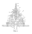
FIG. 3 is a cross-sectional view through the reactor along line A-A of FIG. 2;
FIG. 4 is a cross-sectional view through the reactor along line B-B of FIG. 2; and
FIG. 5 is an enlarged view of region C identified in FIG. 3.
DETAILED DESCRIPTION OF THE INVENTION
With reference to FIGS. 1 to 4, a microwave plasma reactor 10 comprises an electrically conductive housing 12. The housing 12 is preferably formed from electrically conducting material, such as stainless steel, or may have internal electrically conducting surfaces. As illustrated, the housing 12 may have a rectangular cross-section. A slot 14 is formed in the housing 12, for example by machining, and extends across the width of the housing 12 to provide a resonant cavity of the reactor 10. One end of the resonant cavity 14 is connected to a waveguide 16 for conveying microwave radiation from a microwave generator (not shown) into the resonant cavity 14. The other end of the resonant cavity 14 is connected to a short circuit 18.
The waveguide 16 comprises a first, substantially rectangular body portion 20 having a height h1 substantially parallel to the TE01 electric field of the microwave radiation conveyed through the waveguide 16 to the resonant cavity 14, and a width w orthogonal to the electric field of the microwave radiation. The waveguide 16 also comprises a second, substantially rectangular body portion 22 facing the resonant cavity 14, the second body portion 22 having a height h2 and a width w, where h2<h1. In the illustrated example, the second body portion 22 has a height of approximately one third of the height of the first body portion 20.
The waveguide 16 further comprises a tapered, convergent portion 24 of width w located between the first and second body portions 20, 22. The tapered portion 24 comprises a first end surface 25 a adjacent the first body portion 20 of height h1 and width w, and a second end surface 25 b adjacent the second body portion 22 of height h2 and width w. The tapered portion 24 further comprises first and second side surfaces 25 c, 25 d extending between the end surfaces 25 a, 25 b and inclined at an acute angle to the second side surface 25 b such that the first and second body portions 20, 22 are co-axial. The tapered portion 24 has a length/in the direction of propagation of the microwave radiation through the waveguide 16, where l is equal to approximately one half of the wavelength of the microwave radiation.
The short circuit 18 provides an extension of the waveguide 16 on the opposite side of the resonant cavity 14. The short circuit 18 comprises a chamber 27 defined in part by an end plate 26 that is distanced from the end of the second portion 22 of the waveguide 16 such that the incident microwave radiation is reflected by the end plate 26 to form an electromagnetic standing wave within the resonant cavity 14. The position of the end plate 26 relative to the end of the second portion 22 of the waveguide 16 may be adjustable.
The short circuit 18 comprises a tuner 29 spaced from the end plate 26 for tuning the short circuit 18. In the illustrated example, the tuner comprises a screw 29 threaded into the top surface of the short circuit 18 such that the body of the screw extends into the chamber 27 substantially perpendicular to the direction of propagation of the microwave radiation through the chamber 27. By turning the head 29 a of the screw 29, the end of the screw 29 can be raised or lowered within the chamber 27 to tune the short circuit 18.
The resonant cavity 14 houses two dielectric plate members 28, 30, preferably formed from PTFE or other suitable material for retaining adequate corrosion resistance whilst being substantially transparent to the microwave radiation conveyed through the resonant cavity 14. Each plate member 28, 30 has a flat sidewall portion 32 extending orthogonally to the direction of propagation of the microwave radiation through the resonant cavity 14, and a curved sidewall portion 34 which define in part a substantially cylindrical gas chamber 36 within the resonant cavity 14. The gas chamber 36 may have a circular or elliptical cross-section.
Each plate member 28, 30 has a first bore 38 formed therein providing a gas inlet into the gas chamber 36 of the resonant cavity 14. In the illustrated reactor 10, one of the bores 38 is aligned with a gas inlet port 40 formed in a sidewall of the housing 12 for receiving gas from a first gas conduit 42 mounted on the housing 12. A second gas port may optionally be formed in the opposite sidewall of the housing 12 for receiving gas from a second gas conduit, which gas may be the same as, or dissimilar to, the gas entering the gas chamber 36 from the first gas conduit 42. Each gas inlet is preferably configured so that gas enters the gas chamber 36 from the first gas conduit 42 substantially tangentially, so that the gas swirls inwardly within the gas chamber 36 towards the centre of the gas chamber 36. A gas outlet port 44 is formed in the base of the housing 12 for conveying gas from the gas chamber 36 to a second gas conduit 46. The gas outlet port 44 extends transversely of, and is preferably co-axial with, the gas chamber 36.
Each plate member 28, 30 also has a smaller second bore 48 formed therein. One of the bores 48 is aligned with an aperture 50 formed in a sidewall of the housing and closed by a transparent cover plate 52 to provide an inspection window for enabling a user to observe a plasma generated within the gas chamber 36 of the resonant cavity 14 during use of the reactor 10.
A cylindrical bore 54 is also formed in the housing 12, the bore 54 extending transversely of the resonant cavity 14 and defining with the resonant cavity a reactor chamber of the reactor 10. The bore 54 is preferably substantially co-axial with the gas chamber 36 and gas outlet port 44. The bore 54 receives an electrically conducting assembly 56. The assembly 56 comprises an electrically conducting member 58 and a holder 60 for holding the electrically conducting member 58.
The electrically conducting member 58 comprises an elongate tube 62, which may be formed from copper or other electrically conducting material, and which engages a tubular tip 64, as illustrated in more detail in FIG. 5. The tip 64 is preferably formed from corrosion and heat resistant material, such as tungsten or a tungsten alloy, for example an alloy of tungsten and lanthanum. The tip 64 may be provided with a plurality of apertures 65 extending thereabout to enable a gas flowing between the gas inlet 38 and the gas outlet 44 to pass radially through the tip 64 and thereby enhance the cooling of the tip 64. The apertures 65 are preferably dimensioned so that microwave radiation passes through the apertures 65.
The holder 60 is preferably formed from electrically conducting material, such as stainless steel or anodised aluminium. The electrically conducting member 58 and holder 60 are preferably at electrical ground during use of the reactor 10. The holder 60 has a hollow interior within which the tube 62 and tip 64 of the electrically conducting member 58 are preferably a sliding fit. The holder 60 comprises a first body portion 66 having an outwardly extending skirt 68, which is located on a flanged opening 70 of the bore 54 of the housing 12. An O-ring 72 is provided between the skirt 68 and the flanged opening 70 to form an air-tight seal, the skirt 68 being clamped to the flanged opening 70 by a clamp chain 74 extending thereabout. As illustrated in FIG. 3, the O-ring 72 is preferably located outside of the reactor chamber and therefore outside of the electromagnetic field generated therein, and may extend about an annular ring 76 depending downwardly from the skirt 68, the annular ring having an inner diameter that is substantially equal to the diameter of the bore 54, and which makes electrical contact with the housing 12. Alternatively, the base of the skirt 68 may make electrical contact with the housing 12.
The holder 60 further comprises a second, elongate body portion 78 that extends into the bore 54. The second body portion 78 of the holder 60 terminates with a conical projection 80, which preferably does not protrude into the gas chamber 36. The internal diameter of the second body portion 78 decreases at the conical projection 80 to provide a shoulder 82 that engages a rim 84 of the tip 64 to retain the tip 64 within the holder 60. The second body portion 78 of the holder 60 is preferably integral with both the first body portion 66 and the skirt 68.
As illustrated in FIG. 5, the tip 64 preferably protrudes into the gas chamber 36. The length of the tip 64, and/or the length of the second body portion 78 of the holder 60, is preferably chosen so that the tip 64 extends a predetermined distance into the standing wave generated within the resonant cavity 14 depending on the frequency of the microwave radiation supplied to the resonant cavity 14.
The tube 62 is preferably held in electrical contact with the holder 60. As illustrated, a metal spring 86 or other electrically conducting item, may be located within the holder 60 such that one end of the spring 86 engages a first annular projection 88 formed on the tube 62 and the other end of the spring 86 engages a metallic lock nut 90 threaded into the holder 60.
The tube 62 has a second annular projection 92 spaced from the first annular projection 88 to define an annular channel 94 between the holder 60 and the tube 62. A flow of cooling water is supplied to the annular channel 94, the water being supplied to the annular channel 94 through a coolant inlet port 96 passing through the holder 60, and being exhausted from the annular channel 94 through a coolant outlet port 98 passing through the holder 60 and located substantially opposite the coolant inlet port 96.
Depending on the power of the electromagnetic radiation conveyed to the resonant cavity, the intensity of electric field created within the resonant cavity 14 may be insufficient to ignite a plasma within the gas chamber 36. Therefore, a glow-discharge electrode assembly 100 may be housed within the electrically conducting member 58. The electrode assembly 100 comprises a plasma-ignition, glow-discharge electrode 102, which is in the form of an elongate, high voltage electrode located concentrically within, but spaced from, the tube 62 of the electrically conducting member 58. A connector 104 connects the electrode 102 with a power supply. The electrode 102 may be threaded into a conformingly-threaded aperture located concentrically with the lock nut 90. A gas inlet 106 is formed within the tube 62 for receiving a flow of a glow-discharge gas, such as nitrogen, a noble gas, or any other substantially inert and ionisable gas, from a gas inlet port 108 extending radially through the first body portion 66 of the holder 60. The gas inlet port 108 receives the glow-discharge gas from a connector 110 attached to the holder for connecting the gas inlet port 108 to a source of the glow-discharge gas. The gas inlet 106 is preferably arranged tangentially with respect to the bore of the tube 62 of the electrically conducting member 58 to promote formation of a helical flow path around electrode 102 generally downwardly towards the tip 64 of the electrically conducting member 58.
As an alternative to providing a glow-discharge electrode assembly, the microwave generator may be configured such that the power of the electromagnetic field is initially relatively high, for example, around 6 kW for between 1 and 5 seconds, to ignite a plasma within the gas chamber 36. The microwave generator may be configured to then reduce the power of the microwave radiation, for example to between 2 and 3 kW, or to any other power sufficient to sustain the plasma within the gas chamber 36.
As illustrated in FIG. 2, when the holder 60 is mounted on the housing 12, the electrically conducting member 58 extends into the bore 54 substantially perpendicular to the direction of propagation of the microwaves through the gas chamber 36, and is substantially co-axial with both the gas chamber 36 and the gas outlet port 44. The tip 64 of the electrically conducting member 58 is preferably located at a maximum intensity of the electromagnetic field formed within the resonant cavity 14 during use of the reactor 10.
Means may be provided for maintaining the gas chamber 36 at an elevated temperature, preferably at a temperature between 20 and 150° C., during use of the reactor 10. For example, the gas chamber 36 may be heated, insulated or provided with restricted cooling to maintain the gas chamber 36 at or around the desired elevated temperature.
During normal use of the reactor 10, a flow of cooling water is supplied to the annular channel 94. A gas is pumped into gas chamber 36 through the gas inlet port 40, flows spirally within the gas chamber 36 and passes beneath the tip 64 of the electrically conducting member 58 before leaving the gas chamber 36 through the gas outlet port 44 and entering the second gas conduit 46.
Microwave radiation is fed into the resonant cavity 14, and thus into the gas chamber 36, for a magnetron by the waveguide 16. The end plate 26 of the short circuit 18 reflects the microwaves to form a standing wave within the resonant cavity 14, with the tip 64 of the electrically conducting member 58 intensifying the electric field within the gas chamber 36. The tapered portion 24 of the waveguide 16 serves to inhibit the transmission and reflection of microwave radiation from the interface between the first and second body portions 20, 22 of the waveguide 16 whilst maximising the energy absorption of the plasma. The geometry and position of the lower surface 112 of the skirt 68 of the holder 60 relative to the tip 64 of the electrically conducting member 58 is chosen so that the lower surface 112 of the skirt 68 provides, with the inner surface of the bore 54 of the housing 12 and the outer surface of the second body portion of the holder 60, a co-axial tuner for matching the impedance in the plane of the electrically conducting member 58 to the impedance of the waveguide 16 at the frequency of the microwave radiation.
When a glows-discharge electrode assembly 100 is used to ignite a plasma within the gas chamber 36, the glow-discharge gas is caused to flow through the gas inlet port 106 of the tube 62 and into the bore of the tube 62. A low-voltage, high-current source is connected to the electrode 102, and a high voltage is applied temporarily to the electrode 102. The high voltage results in a corona discharge through the glow-discharge gas from the tip of the electrode 102 towards a proximal portion of the tube 62. That corona discharge provides a path through which a large current from the low voltage source can flow to ground. Flow of the large current causes formation of a glow discharge in the glow-discharge gas. The glow discharge thus formed is caused by the flow of the glow-discharge gas within the tube 62 to move from the tip 64 of the electrically conducting member 58 into the gas chamber 36. Microwave radiation within the gas chamber 36 is able to couple efficiently to the glow discharge and, in typically less than one second, the plasma ignites, leading to a stable microwave plasma which can be maintained by means of the microwave radiation supplied to the gas chamber 36 alone after the power supply to the electrode 102 is switched off (typically within two or three seconds).
The plasma initiated within the gas chamber 36 is carried out from the gas chamber 36 through the gas outlet port 44 with the gas flowing through the gas chamber 36, and is contained within the second gas conduit 46. The plasma thus resembles a flame generated beneath the tip 64 and extending out through the gas outlet port 44 into the second gas conduit 46. Due to the high temperature created within the second gas conduit 46 during use of the reactor 10, a coolant such as water may be sprayed over the outer surface of the second gas conduit 46 to cool the second gas conduit 46.
The microwave plasma generated within the gas chamber 36 may be used for a number of purposes. For example, the plasma may be used to destroy halogenated species, such unused perfluorinated and/or hydrofluorocarbon chamber cleaning and etching gases, silane or ammonia contained within the gas stream passing through the chamber. A reactant such as H2 or H2O for reacting with these gases may be supplied to the gas chamber 36 with the glow-discharge gas for reacting with the gases within the plasma generated beneath the tip 64 of the electrically conducting member 58. Where the gases to be destroyed are chemically incompatible, the gas chamber 36 may be provided with a plurality of gas inlets, as described above, so that the incompatible gases may be conveyed separately to the gas chamber 36.
The presence of the tapered portion of the waveguide serves to tune the waveguide to inhibit the reflection of microwave radiation within the waveguide without reducing the energy absorption into the plasma generated within the resonant cavity.
The tapered portion of the waveguide is preferably located adjacent the chamber, and preferably has a length in the direction of propagation of microwave radiation therethrough equal to approximately one half of the wavelength of the microwave radiation.
The tapered portion of the waveguide preferably has a first, preferably substantially rectangular end surface for receiving the microwave radiation and having a first height substantially parallel to the TE01 electric field of the microwave radiation, and a second, preferably substantially rectangular, end surface opposite the first end surface and having a second height smaller than the first. The height of the second end surface is preferably substantially equal to the height of the resonant cavity. By reducing the height of the waveguide from the first to the second height, the intensity of the electric field is increased. The tapered portion of the waveguide preferably comprises two convergent side surfaces each extending between and being inclined at an acute angle to the first end surface.
For rectangular waveguides having approximately the same width orthogonal to electric field, the increase in the intensity of the electric field is directly proportional to the reduction in the height of the waveguide. The increase in the intensity of the electric field may be sufficient that a plasma can be generated within the resonant cavity from the microwave radiation alone.
Due to the containment of a plasma within the conduit means, means are preferably provided for cooling the conduit means. For example, means for spraying a coolant such water or other aqueous solution on to the outer surface of the conduit means may be provided to cool the conduit means.
The means for forming an electromagnetic standing wave within the resonant cavity preferably comprises a second chamber mounted on the reactor chamber opposite the waveguide for receiving the microwave radiation from the resonant cavity and having an end surface extending substantially perpendicular to the direction of propagation of the microwaves through the chamber for reflecting the microwave radiation back into the resonant cavity. In order to optimise energy absorption into the plasma sustained within the resonant cavity, the second chamber preferably houses tuning means spaced from the end surface of the second chamber. The tuning means may comprise an electrically conducting, preferably cylindrical tuner extending perpendicular to the direction of propagation of microwave radiation through the second chamber, and which is preferably moveable relative to the second chamber to tune the second chamber.
The resonant cavity preferably comprises at least one dielectric insert located therein defining a substantially cylindrical gas chamber for receiving gas from the gas inlet and conveying gas to the gas outlet, and wherein the gas outlet is substantially co-axial with the gas chamber. The gas chamber may have a circular or elliptical cross-section. The at least one dielectric insert may conveniently comprise two dielectric plate members each having a curved sidewall portion.
In order to increase the electric field within the resonant cavity, the reactor preferably comprises an electrically conducting member protruding into the electromagnetic field within the resonant cavity, preferably at a location at which the intensity of the electric field is at a peak, and preferably extending into the electromagnetic field substantially perpendicular to the direction of propagation of the microwaves through the reactor chamber. The inventors have found that the presence of a single electrically conducting member protruding into the resonant cavity can intensify the electric field to such an extent that a plasma can be ignited and sustained by the microwave radiation having a relatively low power, for example between 2 and 6 kW.
Due to possible erosion of the electrically conducting member during use of the reactor, the electrically conducting member preferably comprises a replaceable tip protruding into the resonant cavity. The tip is preferably formed from corrosion and heat resistant material, such as tungsten, copper or a tungsten alloy. In order to provide cooling of the tip, thus extending its life, during use of the reactor, the tip may optionally be hollow and comprise a plurality of apertures extending thereabout. The gas flowing between the gas inlet and the gas outlet of the resonant cavity can pass through the apertures to cool the tip. Each of the apertures preferably has a diameter sized to enable the microwave radiation to pass therethrough.
The electrically conducting member preferably comprises an electrically conducting body portion engaging the tip. An annular coolant channel may be provided, the annular channel extending about the electrically conducting body portion, with means being provided for conveying a coolant to and from the annular channel.
The electrically conducting body portion preferably comprises a gas inlet port for receiving a reactant for reacting with a gas conveyed through the resonant cavity, the electrically conducting body portion preferably comprising a passageway for conveying the reactant into the resonant cavity. When the reactor is provided as part of a plasma abatement system, depending on the composition of the gas to be abated and which is conveyed through the chamber, it can be advantageous to introduce a reactant into the resonant cavity for reacting with the gas to be abated. For example, when the gas to be abated is a perfluorinated or hydrofluorocarbon compound, for example, one of CF4, C2F6, CHF3, C3F8, C4F8, NF3 and SF6, a reactant such as H2 or H2O may be conveyed into the resonant cavity through a bore of the electrically conducting member to form H or OH radicals within the plasma for reacting with the gas to be abated.
The electrically conducting member is preferably located opposite the gas outlet. The gas inlet preferably extends through said at least one dielectric insert, and is preferably arranged to introduce gas into the gas chamber substantially tangentially. This encourages the gas to spiral within the chamber and achieve a uniform pressure drop in the gas beneath the tip to optimise the plasma. The reactor chamber preferably comprises a transparent inspection window located in a sidewall thereof, said at least one dielectric insert having a bore formed therein extending between the gas chamber and the window.
The presence of the electrically conducting member within the electric field may disturb the impedance matching between the waveguide and the resonant cavity, and this can lead to reflection of microwave radiation back through the waveguide towards the microwave generator, and thus reduce the energy absorption into the plasma. If the reflected energy is too high, the microwave generator may be damaged. Therefore, a tuner may be provided co-axial with the electrically conducting member so that the impedance in the plane of the electrically conducting member matches the impedance of the waveguide at the frequency of the microwave radiation.
The electrically conducting member is preferably held within a holder mounted on the chamber. The chamber preferably comprises a cylindrical bore located adjacent the resonant cavity, with the holder extending into the bore. Both the holder and the chamber are preferably formed from electrically conducting material, with the holder making electrical contact with the chamber. The holder preferably comprises an outwardly extending skirt that is mounted on the chamber to form a gas-tight seal between the chamber and the holder. The skirt may make electrical contact with the chamber. Otherwise, an annular ring depending downwardly from the skirt may make electrical contact with the chamber. The distance between the base of the skirt and the end of the electrically conducting member is preferably chosen to maximise the electromagnetic field within the resonant cavity. The holder preferably comprises an elongate body portion having a conical projection for retaining the tip of the electrically conducting member therein.
The electrically conducting member may house means for igniting a plasma within the resonant cavity. The means for igniting the plasma preferably comprises means for generating a glow discharge, which preferably comprises an elongate electrode located within the electrically conducting member. A glow-discharge gas is preferably conveyed to the electrode for forming the glow discharge, the electrically conducting member providing a passageway for enabling the glow-discharge gas to convey the glow discharge to the resonant cavity for ignition of the plasma therein. The glow-discharge gas may be nitrogen or a noble gas or any other substantially inert and ionisable gas. When a reactant is required for reacting with the gas conveyed through the resonant cavity, the reactant may be contained within the glow-discharge gas.
Circuitry may be provided for providing a voltage sufficiently high to initiate the glow discharge and for sustaining the glow discharge, preferably for at least 0.1 seconds. Generation of the glow discharge may be ceased after the plasma is ignited within the resonant cavity; thus the glow discharge may generated for up to 10 seconds or for example for up to 5 seconds, for example for from 1 to 5 seconds.
The reactor preferably comprises a microwave generator for generating the microwave radiation. As an alternative to providing a means for igniting the plasma, the generator may be configured to generate the microwave radiation at a power sufficient to ignite a plasma within the resonant cavity, for example, between 2 and 6 kW. The generator may be configured to reduce the power at which the microwave radiation is generated, for example, to between 2 and 3 kW, after a predetermined period of time, for example for from 1 to 5 seconds.
The present invention also provides apparatus for treating a gas stream exhaust from a process tool, the apparatus comprising a microwave plasma reactor as aforementioned.
While the foregoing description and drawings represent the preferred embodiments of the present invention, it will be apparent to those skilled in the art that various changes and modifications may be made therein without departing from the true spirit and scope of the present invention.

Claims (32)

We claim:
1. A microwave plasma reactor comprising:
a reactor chamber;
a microwave resonant cavity located within the reactor chamber, wherein the microwave resonant cavity comprises a gas inlet and a gas outlet;
a waveguide for conveying microwave radiation to the microwave resonant cavity, the waveguide having a convergent tapered portion and connected to one end of the resonant cavity;
means for forming an electromagnetic standing wave within the microwave resonant cavity from the microwave radiation for initiating and sustaining a plasma within the microwave resonant cavity; and
conduit means extending from the gas outlet for containing a plasma conveyed from the resonant cavity with a gas flowing from the gas inlet to the gas outlet, and
an electrically conductive member comprising a replaceable tip protruding into the resonant cavity and located at a maximum intensity of the electromagnetic field formed within the resonant cavity during use of the microwave plasma reactor, the tip intensifying the electric field within the microwave resonant cavity, wherein the microwave resonant cavity further comprises at least one dielectric insert, wherein the at least one dielectric insert comprises a bore fluidly connected to the gas inlet and located in a propagation path of the microwave radiation along the waveguide, and defines a substantially cylindrical gas chamber for receiving gas from the gas inlet and conveying gas to the gas outlet, and wherein the gas outlet is substantially co-axial with the gas chamber, and the gas inlet is substantially tangential to the gas chamber.
2. The microwave plasma reactor of claim 1, wherein the convergent tapered portion of the waveguide has a first substantially rectangular first end surface at one end thereof, a second substantially rectangular first end surface at the other end thereof proximate the microwave resonant cavity, and a height orthogonal to the direction of propagation of microwave radiation therethrough, and wherein the height of the convergent tapered portion of the waveguide decreases from the first end portion to the second end portion.
3. The microwave plasma reactor of claim 2, wherein the convergent tapered portion of the waveguide comprises two convergent side surfaces each extending between and being inclined at an acute angle to the first end surface.
4. The microwave plasma reactor of claim 2, wherein the height of the first end portion is approximately three times that of the second end portion.
5. The microwave plasma reactor of claim 2, wherein the height of the second end portion is approximately equal to the height of the microwave resonant cavity.
6. The microwave plasma reactor of claim 1, wherein the tapered portion of the waveguide is located adjacent to the reactor chamber.
7. The microwave plasma reactor of claim 1, wherein the convergent tapered portion of the waveguide has a length in the direction of propagation of microwave radiation therethrough equal to approximately one half of the wavelength of the microwave radiation.
8. The microwave plasma reactor of claim 1, wherein the waveguide comprises a first body portion and a second body portion from which microwave radiation propagating therethrough enters the microwave resonant cavity, the convergent tapered portion of the waveguide being located between the body portions of the waveguide.
9. The microwave plasma reactor of claim 1, further comprising means for cooling the conduit means.
10. The microwave plasma reactor of claim 9, wherein the means for cooling the conduit means comprises means for spraying a coolant on to an outer surface of the conduit means.
11. The microwave plasma reactor of claim 1, wherein the means for forming an electromagnetic standing wave within the microwave resonant cavity comprises a second chamber mounted on the reactor chamber opposite the waveguide for receiving the microwave radiation from the microwave resonant cavity and having an end surface extending substantially perpendicular to the direction of propagation of the microwave radiation through the reactor chamber for reflecting the microwave radiation back into the microwave resonant cavity.
12. The microwave plasma reactor of claim 11, wherein the second chamber houses tuning means spaced from the end surface of the second chamber.
13. The microwave plasma reactor of claim 12, wherein the tuning means comprises an electrically conducting tuner extending substantially perpendicular to the direction of propagation of microwave radiation through the second chamber.
14. The microwave plasma reactor of claim 13, wherein the electrically conducting tuner is moveable relative to the second chamber.
15. The microwave plasma reactor of claim 13, wherein the electrically conducting tuner is substantially cylindrical.
16. The microwave plasma reactor of claim 1, wherein the gas outlet extends substantially orthogonal to the direction of propagation of the microwave radiation through the reactor chamber.
17. The microwave plasma reactor of claim 1, wherein the reactor chamber has a circular or elliptical cross-section.
18. The microwave plasma reactor of claim 1, wherein the at least one dielectric insert comprises two dielectric plate members each comprising a curved sidewall portion.
19. The microwave plasma reactor of claim 1, wherein the gas inlet extends through the at least one dielectric insert.
20. The microwave plasma reactor of claim 1, wherein the gas inlet is arranged to introduce gas into the gas chamber substantially tangentially.
21. The microwave plasma reactor of claim 1, wherein the reactor chamber further comprises a transparent inspection window located in a sidewall thereof, the at least one dielectric insert comprising a bore formed therein extending between the gas chamber and the transparent inspection window.
22. The microwave plasma reactor of claim 1, wherein the replaceable tip is hollow and comprises a plurality of apertures extending thereabout.
23. The microwave plasma reactor of claim 22, wherein each aperture of the plurality of apertures defines a diameter sized to enable the microwave radiation to pass therethrough.
24. The microwave plasma reactor of claim 1, wherein the replaceable tip is formed from tungsten, copper or a tungsten alloy.
25. The microwave plasma reactor of claim 1, wherein the electrically conductive member comprises an electrically conductive body portion engaging the replaceable tip.
26. The microwave plasma reactor of claim 25, further comprising:
an annular coolant channel extending about the electrically conductive body portion; and
means for conveying a coolant to and from the annular coolant channel.
27. The microwave plasma reactor of claim 26, wherein the electrically conductive body portion comprises a gas inlet port for receiving a reactant for reacting with a gas conveyed through the microwave resonant cavity, the electrically conductive body portion comprising a passageway for conveying the reactant into the microwave resonant cavity.
28. The microwave plasma reactor of claim 1, wherein the electrically conductive member extends into the electromagnetic field substantially perpendicular to the direction of propagation of the microwave radiation through the reactor chamber.
29. The microwave plasma reactor of claim 1, wherein the electrically conductive member is located opposite the gas outlet.
30. The microwave plasma reactor of claim 1, wherein the electrically conductive member houses means for igniting a plasma within the microwave resonant cavity.
31. The microwave plasma reactor of claim 1, further comprising a microwave generator for generating the microwave radiation, the microwave generator being configured to generate the microwave radiation at a power sufficient to initiate a plasma within the microwave resonant cavity.
32. The microwave plasma reactor of claim 31, wherein the microwave generator is configured to reduce the power at which the microwave generator generates the microwave radiation after a predetermined period of time.
US11/990,257 2005-08-15 2006-07-27 Microwave plasma reactor Active 2030-03-22 US8776719B2 (en)

Applications Claiming Priority (3)

Application Number Priority Date Filing Date Title
GBGB0516695.4A GB0516695D0 (en) 2005-08-15 2005-08-15 Microwave plasma reactor
GB0516695.4 2005-08-15
PCT/GB2006/002794 WO2007020373A1 (en) 2005-08-15 2006-07-27 Microwave plasma reactor

Publications (2)

Publication Number Publication Date
US20100006227A1 US20100006227A1 (en) 2010-01-14
US8776719B2 true US8776719B2 (en) 2014-07-15

Family

ID=35098307

Family Applications (2)

Application Number Title Priority Date Filing Date
US11/990,255 Active 2028-09-16 US8518162B2 (en) 2005-08-15 2006-07-27 Method of treating a gas stream
US11/990,257 Active 2030-03-22 US8776719B2 (en) 2005-08-15 2006-07-27 Microwave plasma reactor

Family Applications Before (1)

Application Number Title Priority Date Filing Date
US11/990,255 Active 2028-09-16 US8518162B2 (en) 2005-08-15 2006-07-27 Method of treating a gas stream

Country Status (10)

Country Link
US (2) US8518162B2 (en)
EP (1) EP1915768B1 (en)
JP (2) JP5027808B2 (en)
KR (1) KR101286348B1 (en)
CN (2) CN101248506B (en)
AT (1) ATE509365T1 (en)
GB (2) GB0516695D0 (en)
SG (1) SG186661A1 (en)
TW (2) TWI405239B (en)
WO (1) WO2007020373A1 (en)

Cited By (8)

* Cited by examiner, † Cited by third party
Publication number Priority date Publication date Assignee Title
US20140159572A1 (en) * 2011-04-28 2014-06-12 Gasplas As Method for processing a gas and a device for performing the method
WO2016153757A1 (en) * 2015-03-23 2016-09-29 Applied Materials, Inc. Plasma reactor having digital control over rotation frequency of a microwave field with direct up-conversion
US9627500B2 (en) 2015-01-29 2017-04-18 Samsung Electronics Co., Ltd. Semiconductor device having work-function metal and method of forming the same
US10340124B2 (en) 2015-10-29 2019-07-02 Applied Materials, Inc. Generalized cylindrical cavity system for microwave rotation and impedance shifting by irises in a power-supplying waveguide
US10676353B2 (en) 2018-08-23 2020-06-09 Transform Materials Llc Systems and methods for processing gases
US11471852B2 (en) 2018-08-23 2022-10-18 Transform Materials Llc Systems and methods for processing gases
US11551911B2 (en) * 2017-11-12 2023-01-10 Taiwan Semiconductor Manufacturing Company, Ltd. Grounding cap module, gas injection device and etching apparatus
US11972930B2 (en) 2021-12-06 2024-04-30 Applied Materials, Inc. Cylindrical cavity with impedance shifting by irises in a power-supplying waveguide

Families Citing this family (31)

* Cited by examiner, † Cited by third party
Publication number Priority date Publication date Assignee Title
JP4611409B2 (en) * 2008-09-03 2011-01-12 晃俊 沖野 Plasma temperature control device
KR100965491B1 (en) * 2009-11-02 2010-06-24 박영배 Complex plasma generating device
US9500362B2 (en) 2010-01-21 2016-11-22 Powerdyne, Inc. Generating steam from carbonaceous material
US9338871B2 (en) 2010-01-29 2016-05-10 Applied Materials, Inc. Feedforward temperature control for plasma processing apparatus
US8916793B2 (en) 2010-06-08 2014-12-23 Applied Materials, Inc. Temperature control in plasma processing apparatus using pulsed heat transfer fluid flow
US8880227B2 (en) * 2010-05-27 2014-11-04 Applied Materials, Inc. Component temperature control by coolant flow control and heater duty cycle control
US8653911B2 (en) 2011-07-22 2014-02-18 Triple Cores Korea Atmospheric plasma equipment and waveguide for the same
JP2013026118A (en) * 2011-07-25 2013-02-04 Triplecores Korea Normal pressure plasma device and waveguide therefor
CN102905456B (en) * 2011-07-27 2015-05-20 韩国三重核心株式会社 Atmospheric plasma equipment and waveguide thereof
US10274270B2 (en) 2011-10-27 2019-04-30 Applied Materials, Inc. Dual zone common catch heat exchanger/chiller
KR101382003B1 (en) * 2011-11-04 2014-04-21 (주)트리플코어스코리아 Plasma reactor and and gas scrubber using the same
US9410452B2 (en) 2012-09-05 2016-08-09 Powerdyne, Inc. Fuel generation using high-voltage electric fields methods
KR101581263B1 (en) 2012-09-05 2015-12-31 파워다인, 인코포레이티드 System for generating fuel materials using fischer-tropsch catalysts and plasma sources
WO2014039711A1 (en) 2012-09-05 2014-03-13 Powerdyne, Inc. Fuel generation using high-voltage electric fields methods
US9273570B2 (en) 2012-09-05 2016-03-01 Powerdyne, Inc. Methods for power generation from H2O, CO2, O2 and a carbon feed stock
WO2014039695A1 (en) 2012-09-05 2014-03-13 Powerdyne, Inc. Methods for generating hydrogen gas using plasma sources
BR112015004834A2 (en) 2012-09-05 2017-07-04 Powerdyne Inc method to produce fuel
BR112015004836A2 (en) 2012-09-05 2017-07-04 Powerdyne Inc method for sequestering toxin particles
CN102933016A (en) * 2012-11-28 2013-02-13 吉林大学 Plasma microwave power synthesis system for vehicle-mounted fuel
SG11201507152RA (en) 2013-03-14 2015-10-29 Mks Instr Inc Toroidal plasma abatement apparatus and method
KR101427720B1 (en) 2013-03-27 2014-08-13 (주)트리플코어스코리아 Plasma waveguide using step part and block part
GB2516267B (en) * 2013-07-17 2016-08-17 Edwards Ltd Head assembly
US9240308B2 (en) * 2014-03-06 2016-01-19 Applied Materials, Inc. Hall effect enhanced capacitively coupled plasma source, an abatement system, and vacuum processing system
CN103968882B (en) * 2014-05-22 2016-05-18 哈尔滨工业大学 Microwave and the interactional testing arrangement of weak magnetopasma
EP3309815B1 (en) * 2016-10-12 2019-03-20 Meyer Burger (Germany) AG Plasma treatment device with two microwave plasma sources coupled together and method for operating such a plasma treatment device
US10712005B2 (en) 2017-07-14 2020-07-14 Goodrich Corporation Ceramic matrix composite manufacturing
US10480065B2 (en) * 2017-09-19 2019-11-19 Goodrich Corporation Gas distribution for chemical vapor deposition/infiltration
US11469077B2 (en) * 2018-04-24 2022-10-11 FD3M, Inc. Microwave plasma chemical vapor deposition device and application thereof
CN114560443B (en) * 2022-03-02 2023-07-07 瓮福(集团)有限责任公司 Microwave plasma device for simultaneously preparing hydrogen fluoride and crystalline silicon products
CN115665914B (en) * 2022-12-22 2023-03-10 河北科技大学 Multi-source microwave heating device
CN117373964B (en) * 2023-12-05 2024-03-12 天津吉兆源科技有限公司 Automatic ignition device for microwave remote plasma body

Citations (27)

* Cited by examiner, † Cited by third party
Publication number Priority date Publication date Assignee Title
JPS59103340A (en) 1983-09-21 1984-06-14 Hitachi Ltd Plasma processing apparatus
US4866346A (en) * 1987-06-22 1989-09-12 Applied Science & Technology, Inc. Microwave plasma generator
US4893584A (en) * 1988-03-29 1990-01-16 Energy Conversion Devices, Inc. Large area microwave plasma apparatus
US4970435A (en) 1987-12-09 1990-11-13 Tel Sagami Limited Plasma processing apparatus
US5144199A (en) 1990-01-11 1992-09-01 Mitsubishi Denki Kabushiki Kaisha Microwave discharge light source device
JPH0653170A (en) 1992-03-18 1994-02-25 Nec Corp Ecr plasma etcher
JPH0673567A (en) 1992-08-28 1994-03-15 Hitachi Ltd Microwave plasma treatment device
JPH06112161A (en) 1992-09-24 1994-04-22 Hitachi Ltd Plasma processor
US5310426A (en) 1989-08-03 1994-05-10 Uha Mikakuto Precision Engineering Research Institute Co., Ltd. High-speed film forming method by microwave plasma chemical vapor deposition (CVD) under high pressure and an apparatus therefor
US5349154A (en) * 1991-10-16 1994-09-20 Rockwell International Corporation Diamond growth by microwave generated plasma flame
JPH06299357A (en) 1993-04-15 1994-10-25 Mitsubishi Heavy Ind Ltd Chemical vapor deposition device by electron cyclotron resonance plasma
US5418430A (en) * 1992-11-26 1995-05-23 United Kingdom Atomic Energy Authority Plasma generator with field-enhancing electrodes
US5453125A (en) 1994-02-17 1995-09-26 Krogh; Ole D. ECR plasma source for gas abatement
US5517085A (en) 1992-10-23 1996-05-14 Jurgen Engemann Apparatus including ring-shaped resonators for producing microwave plasmas
US5603771A (en) * 1992-09-24 1997-02-18 Office National D'etudes Et De Recherches Aerospatiales Chemical vapor deposition apparatus activated by a microwave plasma
US5825485A (en) * 1995-11-03 1998-10-20 Cohn; Daniel R. Compact trace element sensor which utilizes microwave generated plasma and which is portable by an individual
US5874705A (en) * 1994-07-19 1999-02-23 Ea Technology Limited Method of and apparatus for microwave-plasma production
US5902404A (en) * 1997-03-04 1999-05-11 Applied Materials, Inc. Resonant chamber applicator for remote plasma source
US5973289A (en) * 1995-06-07 1999-10-26 Physical Sciences, Inc. Microwave-driven plasma spraying apparatus and method for spraying
WO2001020640A1 (en) * 1999-09-14 2001-03-22 Robert Bosch Gmbh Device and method for generating a local plasma by micro-structure electrode discharges with microwaves
EP1093847A1 (en) 1999-04-12 2001-04-25 Mitsubishi Heavy Industries, Ltd. Organic halogen compound decomposing device and operation control method therefor, and organic halogen compound decomposing method
US20010019237A1 (en) 2000-03-02 2001-09-06 Tokyo Electron Limited Plasma processing apparatus
US6298806B1 (en) 1997-07-16 2001-10-09 L'air Liquide, Societe Anonyme Pour L'etude Et L'exploitation Des Procedes Georges Claude Device for exciting a gas by a surface wave plasma
US20020007912A1 (en) * 1999-04-12 2002-01-24 Mohammad Kamarehi Coolant for plasma generator
US20020020691A1 (en) * 2000-05-25 2002-02-21 Jewett Russell F. Methods and apparatus for plasma processing
US6712927B1 (en) * 1998-06-11 2004-03-30 Applied Materials Inc. Chamber having process monitoring window
WO2004098246A1 (en) 2003-04-30 2004-11-11 The Boc Group Plc Apparatus and method for forming a plasma

Family Cites Families (16)

* Cited by examiner, † Cited by third party
Publication number Priority date Publication date Assignee Title
US2002002A (en) * 1931-11-20 1935-05-21 Deere & Co Tractor
JPS62155934A (en) * 1985-12-28 1987-07-10 Canon Inc Vapor phase exciter
DE4132558C1 (en) * 1991-09-30 1992-12-03 Secon Halbleiterproduktionsgeraete Ges.M.B.H., Wien, At
US6045618A (en) * 1995-09-25 2000-04-04 Applied Materials, Inc. Microwave apparatus for in-situ vacuum line cleaning for substrate processing equipment
TW376547B (en) * 1997-03-27 1999-12-11 Matsushita Electric Ind Co Ltd Method and apparatus for plasma processing
JP2000133494A (en) * 1998-10-23 2000-05-12 Mitsubishi Heavy Ind Ltd Microwave plasma generation device and method
US6263830B1 (en) * 1999-04-12 2001-07-24 Matrix Integrated Systems, Inc. Microwave choke for remote plasma generator
WO2000061286A1 (en) * 1999-04-12 2000-10-19 Mitsubishi Heavy Industries, Ltd. Method for decomposition-treating organic halogen compound and decomposing device
JP2000296326A (en) * 1999-04-12 2000-10-24 Mitsubishi Heavy Ind Ltd Method for controlling operation of organohalogen compound decomposing device
KR100767762B1 (en) 2000-01-18 2007-10-17 에이에스엠 저펜 가부시기가이샤 A CVD semiconductor-processing device provided with a remote plasma source for self cleaning
JP4252702B2 (en) 2000-02-14 2009-04-08 株式会社荏原製作所 Apparatus and method for preventing adhesion of reaction by-products in piping
US6673323B1 (en) * 2000-03-24 2004-01-06 Applied Materials, Inc. Treatment of hazardous gases in effluent
DE60132089T2 (en) 2000-05-29 2008-12-11 ADTEC Plasma Technology Co., Ltd., Fukuyama City DEVICE FOR TREATING GASEN MIITELS PLASMA
EP1448030A4 (en) * 2002-08-30 2006-11-22 Sekisui Chemical Co Ltd Plasma processing system
JP2004216231A (en) * 2003-01-10 2004-08-05 Toshiba Corp Method for decomposing compound by high frequency plasma and compound decomposing apparatus
US6872909B2 (en) * 2003-04-16 2005-03-29 Applied Science And Technology, Inc. Toroidal low-field reactive gas and plasma source having a dielectric vacuum vessel

Patent Citations (28)

* Cited by examiner, † Cited by third party
Publication number Priority date Publication date Assignee Title
JPS59103340A (en) 1983-09-21 1984-06-14 Hitachi Ltd Plasma processing apparatus
US4866346A (en) * 1987-06-22 1989-09-12 Applied Science & Technology, Inc. Microwave plasma generator
US4970435A (en) 1987-12-09 1990-11-13 Tel Sagami Limited Plasma processing apparatus
US4893584A (en) * 1988-03-29 1990-01-16 Energy Conversion Devices, Inc. Large area microwave plasma apparatus
US5310426A (en) 1989-08-03 1994-05-10 Uha Mikakuto Precision Engineering Research Institute Co., Ltd. High-speed film forming method by microwave plasma chemical vapor deposition (CVD) under high pressure and an apparatus therefor
US5144199A (en) 1990-01-11 1992-09-01 Mitsubishi Denki Kabushiki Kaisha Microwave discharge light source device
US5349154A (en) * 1991-10-16 1994-09-20 Rockwell International Corporation Diamond growth by microwave generated plasma flame
JPH0653170A (en) 1992-03-18 1994-02-25 Nec Corp Ecr plasma etcher
JPH0673567A (en) 1992-08-28 1994-03-15 Hitachi Ltd Microwave plasma treatment device
US5603771A (en) * 1992-09-24 1997-02-18 Office National D'etudes Et De Recherches Aerospatiales Chemical vapor deposition apparatus activated by a microwave plasma
JPH06112161A (en) 1992-09-24 1994-04-22 Hitachi Ltd Plasma processor
US5517085A (en) 1992-10-23 1996-05-14 Jurgen Engemann Apparatus including ring-shaped resonators for producing microwave plasmas
US5418430A (en) * 1992-11-26 1995-05-23 United Kingdom Atomic Energy Authority Plasma generator with field-enhancing electrodes
JPH06299357A (en) 1993-04-15 1994-10-25 Mitsubishi Heavy Ind Ltd Chemical vapor deposition device by electron cyclotron resonance plasma
US5453125A (en) 1994-02-17 1995-09-26 Krogh; Ole D. ECR plasma source for gas abatement
US5874705A (en) * 1994-07-19 1999-02-23 Ea Technology Limited Method of and apparatus for microwave-plasma production
US5973289A (en) * 1995-06-07 1999-10-26 Physical Sciences, Inc. Microwave-driven plasma spraying apparatus and method for spraying
US5825485A (en) * 1995-11-03 1998-10-20 Cohn; Daniel R. Compact trace element sensor which utilizes microwave generated plasma and which is portable by an individual
US5902404A (en) * 1997-03-04 1999-05-11 Applied Materials, Inc. Resonant chamber applicator for remote plasma source
US6298806B1 (en) 1997-07-16 2001-10-09 L'air Liquide, Societe Anonyme Pour L'etude Et L'exploitation Des Procedes Georges Claude Device for exciting a gas by a surface wave plasma
US6712927B1 (en) * 1998-06-11 2004-03-30 Applied Materials Inc. Chamber having process monitoring window
EP1093847A1 (en) 1999-04-12 2001-04-25 Mitsubishi Heavy Industries, Ltd. Organic halogen compound decomposing device and operation control method therefor, and organic halogen compound decomposing method
US20020007912A1 (en) * 1999-04-12 2002-01-24 Mohammad Kamarehi Coolant for plasma generator
WO2001020640A1 (en) * 1999-09-14 2001-03-22 Robert Bosch Gmbh Device and method for generating a local plasma by micro-structure electrode discharges with microwaves
US7159536B1 (en) * 1999-09-14 2007-01-09 Robert Bosch Gmbh Device and method for generating a local by micro-structure electrode dis-charges with microwaves
US20010019237A1 (en) 2000-03-02 2001-09-06 Tokyo Electron Limited Plasma processing apparatus
US20020020691A1 (en) * 2000-05-25 2002-02-21 Jewett Russell F. Methods and apparatus for plasma processing
WO2004098246A1 (en) 2003-04-30 2004-11-11 The Boc Group Plc Apparatus and method for forming a plasma

Non-Patent Citations (9)

* Cited by examiner, † Cited by third party
Title
Kawai Yoshinobu, Kojo Daiichi, Murata Masayoshi, Takeuchi Yoshiaki, Uda Kazutaka; English language abstract of Japanese Patent No. JP 6299357 A, entitled "Chemical Vapor Deposition Device by Electron Cyclotron Resonance Plasma," Mitsubishi Heavy Ind Ltd; Oct. 25, 1994.
PCT International Search Report of International Application No. PCT/GB2006/002794; Date of mailing of the International Search Report: Oct. 23, 2006.
PCT Notification of Transmittal of the International Search Report and the Written Opinion of the International Searching Authority, or the Declaration of International Application No. PCT/GB2006/002794; Date of mailing: Oct. 23, 2007.
PCT Written Opinion of the International Searching Authority of International Application No. PCT/GB2006/002794; Date of mailing: Oct. 23, 2006.
Sagawa Seiji, English language abstract of Japanese Patent No. JP 6053170A, entitled "ECR PLasma Etcher," Nippon Electric Co; Feb. 25, 1994.
Tsuchimoto Takashi, Sakumichi Kuniyuki, Suzuki Keizou; English language abstract of Japanese Patent No. JP 59103340 A, entitled "Plasma Processing Apparatus," Hitachi Ltd; Jun. 14, 1984.
United Kingdom Search Report of Application No. GB 0516695.4; Date of mailing: Dec. 23, 2005; Claims searched: All; Date of Search: Dec. 22, 2005.
Watanbe Seiichi, Furuse Muneo; English language abstract of Japanese Patent No. JP 6073567 A, entitled "Microwave Plasma Treatment Device," Hitachi Ltd; Mar. 15, 1994.
Yoshioka Takeshi, Tetsuka Tsutomu, Kazumi Hideyuki, Shirakawa Shinji, Kobayashi Kinya, Shima Kenzo, Suzuki Kazuo; English language abstract of Japanese Patent No. JP 6112161 A; entitled "Plasma Processor," Hitachi Ltd; Apr. 22, 1994.

Cited By (19)

* Cited by examiner, † Cited by third party
Publication number Priority date Publication date Assignee Title
US9293302B2 (en) * 2011-04-28 2016-03-22 Gasplas As Method for processing a gas and a device for performing the method
US20140159572A1 (en) * 2011-04-28 2014-06-12 Gasplas As Method for processing a gas and a device for performing the method
US10734288B2 (en) 2015-01-29 2020-08-04 Samsung Electronics Co., Ltd. Semiconductor device having work-function metal and method of forming the same
US11929289B2 (en) 2015-01-29 2024-03-12 Samsung Electronics Co., Ltd. Semiconductor device having work-function metal and method of forming the same
US9627500B2 (en) 2015-01-29 2017-04-18 Samsung Electronics Co., Ltd. Semiconductor device having work-function metal and method of forming the same
US11462442B2 (en) 2015-01-29 2022-10-04 Samsung Electronics Co., Ltd. Semiconductor device having work-function metal and method of forming the same
US10388574B2 (en) 2015-01-29 2019-08-20 Samsung Electronics Co., Ltd. Semiconductor device having work-function metal and method of forming the same
US11043430B2 (en) 2015-01-29 2021-06-22 Samsung Electronics Co., Ltd. Semiconductor device having work-function metal and method of forming the same
US10153133B2 (en) 2015-03-23 2018-12-11 Applied Materials, Inc. Plasma reactor having digital control over rotation frequency of a microwave field with direct up-conversion
WO2016153757A1 (en) * 2015-03-23 2016-09-29 Applied Materials, Inc. Plasma reactor having digital control over rotation frequency of a microwave field with direct up-conversion
US11195699B2 (en) 2015-10-29 2021-12-07 Applied Materials, Inc. Generalized cylindrical cavity system for microwave rotation and impedance shifting by irises in a power-supplying waveguide
US10340124B2 (en) 2015-10-29 2019-07-02 Applied Materials, Inc. Generalized cylindrical cavity system for microwave rotation and impedance shifting by irises in a power-supplying waveguide
US11551911B2 (en) * 2017-11-12 2023-01-10 Taiwan Semiconductor Manufacturing Company, Ltd. Grounding cap module, gas injection device and etching apparatus
US10676353B2 (en) 2018-08-23 2020-06-09 Transform Materials Llc Systems and methods for processing gases
US11471852B2 (en) 2018-08-23 2022-10-18 Transform Materials Llc Systems and methods for processing gases
US11633710B2 (en) 2018-08-23 2023-04-25 Transform Materials Llc Systems and methods for processing gases
US11634323B2 (en) 2018-08-23 2023-04-25 Transform Materials Llc Systems and methods for processing gases
US11634324B2 (en) 2018-08-23 2023-04-25 Transform Materials Llc Systems and methods for processing gases
US11972930B2 (en) 2021-12-06 2024-04-30 Applied Materials, Inc. Cylindrical cavity with impedance shifting by irises in a power-supplying waveguide

Also Published As

Publication number Publication date
WO2007020373A1 (en) 2007-02-22
TW200727325A (en) 2007-07-16
CN101248506B (en) 2011-09-07
CN101243534B (en) 2010-05-26
SG186661A1 (en) 2013-01-30
JP5027808B2 (en) 2012-09-19
KR101286348B1 (en) 2013-07-23
ATE509365T1 (en) 2011-05-15
TW200712249A (en) 2007-04-01
US8518162B2 (en) 2013-08-27
CN101243534A (en) 2008-08-13
GB0516695D0 (en) 2005-09-21
CN101248506A (en) 2008-08-20
TWI399454B (en) 2013-06-21
JP2009504394A (en) 2009-02-05
KR20080033408A (en) 2008-04-16
EP1915768B1 (en) 2014-09-10
EP1915768A1 (en) 2008-04-30
US20100006227A1 (en) 2010-01-14
TWI405239B (en) 2013-08-11
GB0521961D0 (en) 2005-12-07
JP2009504393A (en) 2009-02-05
JP5600394B2 (en) 2014-10-01
US20110197759A1 (en) 2011-08-18

Similar Documents

Publication Publication Date Title
US8776719B2 (en) Microwave plasma reactor
TWI417931B (en) Plasma abatement device
TWI442836B (en) Plasma reactor
KR101107819B1 (en) Apparatus and method for forming a plasma
JP2007522935A5 (en)
EP3934389A1 (en) Plasma source apparatus
EP1915769B1 (en) Method of treating a gas stream

Legal Events

Date Code Title Description
AS Assignment

Owner name: EDWARDS LIMITED, UNITED KINGDOM

Free format text: ASSIGNMENT OF ASSIGNORS INTEREST;ASSIGNORS:RADOIU, MARILENA;SMITH, JAMES ROBERT;SEELEY, ANDREW JAMES;REEL/FRAME:023091/0917;SIGNING DATES FROM 20090717 TO 20090720

Owner name: EDWARDS LIMITED, UNITED KINGDOM

Free format text: ASSIGNMENT OF ASSIGNORS INTEREST;ASSIGNORS:RADOIU, MARILENA;SMITH, JAMES ROBERT;SEELEY, ANDREW JAMES;SIGNING DATES FROM 20090717 TO 20090720;REEL/FRAME:023091/0917

STCF Information on status: patent grant

Free format text: PATENTED CASE

MAFP Maintenance fee payment

Free format text: PAYMENT OF MAINTENANCE FEE, 4TH YEAR, LARGE ENTITY (ORIGINAL EVENT CODE: M1551)

Year of fee payment: 4

MAFP Maintenance fee payment

Free format text: PAYMENT OF MAINTENANCE FEE, 8TH YEAR, LARGE ENTITY (ORIGINAL EVENT CODE: M1552); ENTITY STATUS OF PATENT OWNER: LARGE ENTITY

Year of fee payment: 8