US8774716B2 - Mobile terminal extension case - Google Patents
Mobile terminal extension case Download PDFInfo
- Publication number
- US8774716B2 US8774716B2 US13/433,389 US201213433389A US8774716B2 US 8774716 B2 US8774716 B2 US 8774716B2 US 201213433389 A US201213433389 A US 201213433389A US 8774716 B2 US8774716 B2 US 8774716B2
- Authority
- US
- United States
- Prior art keywords
- battery
- mobile terminal
- terminal device
- extension case
- covering portion
- Prior art date
- Legal status (The legal status is an assumption and is not a legal conclusion. Google has not performed a legal analysis and makes no representation as to the accuracy of the status listed.)
- Active, expires
Links
- 238000001914 filtration Methods 0.000 claims description 10
- 238000004891 communication Methods 0.000 claims description 6
- 238000005516 engineering process Methods 0.000 description 9
- 238000000034 method Methods 0.000 description 2
- WHXSMMKQMYFTQS-UHFFFAOYSA-N Lithium Chemical compound [Li] WHXSMMKQMYFTQS-UHFFFAOYSA-N 0.000 description 1
- BPKGOZPBGXJDEP-UHFFFAOYSA-N [C].[Zn] Chemical compound [C].[Zn] BPKGOZPBGXJDEP-UHFFFAOYSA-N 0.000 description 1
- 238000013459 approach Methods 0.000 description 1
- 229910052744 lithium Inorganic materials 0.000 description 1
- 238000012986 modification Methods 0.000 description 1
- 230000004048 modification Effects 0.000 description 1
- 238000003032 molecular docking Methods 0.000 description 1
- 238000011160 research Methods 0.000 description 1
Images


Classifications
-
- H04B5/77—
-
- H—ELECTRICITY
- H04—ELECTRIC COMMUNICATION TECHNIQUE
- H04B—TRANSMISSION
- H04B1/00—Details of transmission systems, not covered by a single one of groups H04B3/00 - H04B13/00; Details of transmission systems not characterised by the medium used for transmission
- H04B1/38—Transceivers, i.e. devices in which transmitter and receiver form a structural unit and in which at least one part is used for functions of transmitting and receiving
- H04B1/3827—Portable transceivers
- H04B1/3883—Arrangements for mounting batteries or battery chargers
-
- H—ELECTRICITY
- H04—ELECTRIC COMMUNICATION TECHNIQUE
- H04B—TRANSMISSION
- H04B1/00—Details of transmission systems, not covered by a single one of groups H04B3/00 - H04B13/00; Details of transmission systems not characterised by the medium used for transmission
- H04B1/38—Transceivers, i.e. devices in which transmitter and receiver form a structural unit and in which at least one part is used for functions of transmitting and receiving
- H04B1/3827—Portable transceivers
- H04B1/3888—Arrangements for carrying or protecting transceivers
Definitions
- the instant disclosure relates to an extension case and a mobile terminal assembly using the same; more particularly, to an extension case for a mobile terminal device that incorporates an add-on battery and a radio frequency identification (RFID) antenna.
- RFID radio frequency identification
- a mobile terminal device such as a cell phone
- NFC Near Field Communication
- RFID radio frequency identification
- the NFC technology is able to apply the RFID technology for transmitting data in short distance at low power.
- the use of the NFC technology by allowing two or more terminals to each other close, without requiring any user manipulation that is able to exchange information.
- the majority of the NFC technology is standardized by the European computer vendors alliance. Nokia, Sony, and Philips are involved in standardization and commercialization of the NFC technology.
- the NFC mobile terminal device used for payment has become an important application of the mobile terminal device.
- Traditional NFC antenna is set on the system circuit board of the mobile terminal device, if the NFC antenna is too close to the components of the system circuit board (or the rechargeable battery of the mobile terminal device), the system circuit board will have NFC antenna signal transceiver impact.
- the instant disclosure provides an extension case and a mobile terminal assembly, which can be used for supplying power to the mobile terminal device and causing the mobile terminal device has RFID function.
- Embodiments of the instant disclosure provide an extension case used for adapting on a mobile terminal device.
- the extension case comprises a sheath, an electrical connector, a battery, and a radio frequency identification (RFID) antenna.
- the sheath shieldingly adaptable onto the mobile terminal device, has a covering portion and a buckling portion curvedly extended from an outer edge of the covering portion.
- the electrical connector is arranged on the buckling portion of the sheath for establishing electrical connection with the mobile terminal device.
- the battery is accessibly in the covering portion and electrically connectable with the mobile terminal device through the electrical connector.
- the RFID antenna is electrically connected to the electrical connector and embeddedly arranged in the covering portion adjacent to the battery in an non-overlapping manner.
- the electrical connector and the RFID antenna are respectively arranged on two opposite sides of the battery, and the RFID antenna and the battery are spaced apart.
- the back clip further comprises a circuit board having a filtering module, wherein the battery and the RFID antenna are electrically connected to the electrical connector via the filtering module of the circuit board.
- the back clip further comprises a power assembly set in the buckling portion and electrically connected to the circuit board, wherein the power assembly has a power switch for providing power supply management.
- the power assembly has an electric quantity display used for showing the electric quantity of the battery and a charging port used for charging the battery.
- the circuit board has a display module enabling the mobile terminal device to show information about the RFID antenna.
- a battery vessel and an antenna trough are separately formed on the sheath, the battery is disposed in the battery vessel, and the RFID antenna is disposed in the antenna trough.
- the back clip further comprises a lid engaged to the sheath, wherein the lid is covered and positioned the battery and the RFID antenna.
- the RFID antenna is formed on the covering portion of the sheath.
- Embodiments of the instant disclosure also provide a mobile terminal assembly that comprises a mobile terminal device, a sheath, an electrical connector, a battery, and a near field communication (NFC) antenna.
- the mobile terminal device is having a power connecting port disposed on the edge of the mobile terminal device.
- the sheath, shieldingly adaptable onto the mobile terminal device has a covering portion and a buckling portion curvedly extended from an outer edge of the covering portion.
- the electrical connector is arranged on the buckling portion of the sheath for establishing electrical connection with the mobile terminal device.
- the battery is accessibly in the covering portion and electrically connectable with mobile terminal device through the electrical connector.
- the NFC antenna is electrically connected to the electrical connector and embeddedly disposed in the covering portion adjacent to the battery in a non-overlapping manner.
- the extension case and the mobile terminal assembly which can be used for supplying power to the mobile terminal device by the battery.
- the mobile terminal device has the electronic wallet, the money card, or other related functions by the RFID antenna of the extension case.
- FIG. 1 shows a schematic view of the mobile terminal assembly for a first embodiment of the instant disclosure.
- FIG. 2 shows an exploded schematic view of the mobile terminal assembly for a first embodiment of the instant disclosure.
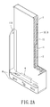
- FIG. 2A shows a profile schematic view of the extension case for a first embodiment of the instant disclosure.
- FIG. 3 shows an exploded schematic view of the extension case for a first embodiment of the instant disclosure.
- FIG. 4 shows a functional block view of the mobile terminal assembly for a first embodiment of the instant disclosure.
- FIG. 5 shows an exploded schematic view of the extension case for a second embodiment of the instant disclosure.
- FIGS. 1-4 are a schematic view of the instant embodiment.
- FIG. 4 is a functional block view of the instant embodiment.
- a mobile terminal assembly has a mobile terminal device 200 and an extension case 100 .
- the mobile terminal device 200 has a power connecting port 201 disposed on the edge of the mobile terminal device 200 .
- the extension case 100 is used for assembling on the edge of the mobile terminal device 200 and electrically connecting to the mobile terminal device 200 via the power connecting port 201 .
- the extension case 100 has a sheath 1 , a battery 2 , a radio frequency identification (RFID) antenna 3 , an electrical connector 4 , a circuit board 5 , a power assembly 6 , and a lid 7 .
- RFID radio frequency identification
- the sheath 1 is shieldingly adaptable onto the mobile terminal device 200 , and has a covering portion 11 and a buckling portion 12 curvedly extended from an outer edge of the covering portion 11 .
- the covering portion 11 is approximately rectangular plate shaped.
- a battery vessel 111 and an antenna trough 112 are separately spaced formed on an inner surface of the covering portion 11 .
- the battery vessel 111 and the antenna trough 112 are approximately arranged in one low along the major axis of the covering portion 11 .
- the buckling portion 12 has two lateral walls 121 and an end wall 122 .
- the two lateral walls 121 are separately arranged at two opposite side of the covering portion 11 .
- the end wall 122 is arranged at one side of the battery vessel 111 away from the antenna trough 112 .
- the height of the buckling portion 12 is approximately equal to the thickness of the mobile terminal device 200 , but in use, it not limited thereto.
- the battery 2 is disposed in the battery vessel 111 of the covering portion 11 .
- the battery 2 can be a rechargeable battery (such as lithium battery) for using repeatedly or an abandoned battery (such as Carbon-zinc battery or alkaline battery) for replaying easily as power of the abandoned battery exhausted.
- an abandoned battery such as Carbon-zinc battery or alkaline battery
- the RFID antenna 3 is disposed in the antenna trough 112 of the covering portion 11 .
- the RFID antenna 3 is embeddedly arranged in the covering portion 11 adjacent to the battery 2 in a non-overlapping manner. More detail, the RFID antenna 3 is arranged outside a region defined by the battery 2 orthogonal projecting to an outer surface 11 of the covering portion 11 (as FIG. 2A shown).
- the RFID antenna 3 can be a near field communication (NFC) antenna 31 , but not limited thereto.
- NFC near field communication
- the electrical connector 4 is set on the buckling portion 12 of the sheath 1 . More detail, the electrical connector 4 is set on an inner surface of the end wall 122 adjacent to the battery vessel 111 . That is, the electrical connector 4 and the RFID antenna 3 are respectively arranged on two opposite sides of the battery 2 , and the RFID antenna 3 and the battery 2 are spaced apart.
- the circuit board 5 is set inside the end wall 122 of the buckling portion 12 , and the circuit board 5 has a filtering module 51 and a display module 52 .
- the battery 2 and the RFID antenna 3 are electrically connected to the electrical connector 4 via the filtering module 51 of the circuit board 5 , thereby filtering the unnecessary signals to reduce the interference between the battery 2 and the RFID antenna 3 .
- the filtering module 51 and the display module 52 can be a hardware nodule or a software module, but not limited thereto.
- the designer can set the display module 52 on a system circuit board (not shown) of the mobile terminal device 200 .
- the power assembly 6 is set in the buckling portion 12 and electrically connected to the circuit board 5 . More detail, the power assembly 6 is exposed from an outer surface of the end wall 122 of the buckling portion 12 away from the battery vessel 111 .
- the power assembly 6 has a power switch 61 , an electric quantity display 62 , and a charging port 63 .
- the power switch 61 is a self-return type push button set on the outer surface of the end wall 122 of the buckling portion 12 .
- the power switch 61 is electrically connected to the circuit board 5 for providing power supply management so as to control the extension case 100 operated or not. For example: the user can press the power switch 61 to control the battery to supply energy or not.
- the electric quantity display 62 and the charging port 63 are electrically connected to the circuit board 5 and set on the outer surface of the end wall 122 of the buckling portion 12 .
- the user can easily know the electric quantity of the battery by the electric quantity display 62 , and the user can conveniently charge the battery 2 of the extension case 100 via the charging port 63 without tacking out the battery 2 .
- the electric quantity display 62 takes a plurality of LEDs for example, and the electric quantity of the battery shows by the number of the lighting LEDs. But in use, the electric quantity display 62 can be a display panel (not shown).
- the lid 7 is plate shaped and engaged to one end portion of the sheath 1 away from the end wall 122 .
- the lid 7 is covered the battery vessel 111 and the antenna trough 112 , so that the battery 2 and the RFID antenna 3 can be covered and positioned by the lid 7 .
- the installed space 113 is redefined by the lid 7 to approach the shape of the mobile terminal device 200 .
- the lid 7 has a resisting ring 71 arranged at the outer edge of the lid 7 to prevent the mobile terminal device 200 from falling down.
- the combination manner of the lid 7 and the sheath 1 is taken the lid 7 and the sheath 1 engaged to each other for example, but not limited thereto.
- the extension case 10 when the extension case 10 is installed on the mobile terminal device 200 to form the mobile terminal assembly, the mobile terminal device 200 is received in the installed space 113 and the outer edge of the mobile terminal device 200 is resisted and limited to the buckling portion 12 of the sheath 1 and the resisting ring 71 of the lid 7 .
- the electrical connector 4 of the extension case 100 is inserted into the power connecting port 201 of the mobile terminal device 200 to achieve electrical connection and fixed position with each other.
- the extension case 100 has a plurality of perforations 8 to correspond the other ports, the horn, the buttons, the camera, and the other relative components of the mobile terminal device 200 .
- One end of the electrical connector 4 is docking and electrically connected to the power connecting port 201 , and the other end of the electrical connector 4 is electrically connected to the battery 2 and the RFID antenna 3 via the circuit board 5 , whereby the battery 2 of the extension case 100 can be used for providing energy to the mobile terminal device 200 .
- the interference between the battery 2 and the RFID antenna 3 can be reduced via the filtering module 51 .
- the operation interface 202 of the mobile terminal device 200 will show information about the battery 2 and the RFID antenna 3 by the display module 52 .
- the extension case 100 can be used for supplying power to the mobile terminal device 200 by the battery 2 .
- the mobile terminal device 200 has the electronic wallet, the money card, or other related functions by the RFID antenna of the extension case 100 .
- an antimagnetic component (not shown) can be set between the rechargeable battery (not shown) of the mobile terminal device 200 and the RFID antenna 3 and the battery 2 , so that the interference generated from the RFID antenna 3 can be reduced.
- FIG. 5 For a second embodiment of the instant disclosure, please refer to FIG. 5 .
- the second embodiment is similar to the first embodiment, and the difference between both is the RFID antenna 3 .
- the RFID antenna 3 of this embodiment can be directly formed on the covering portion 11 of the sheath 1 (such as the bottom of the antenna trough 112 ), and the forming method of the RFID antenna 3 is not limited, for example, the RFID antenna 3 can be formed on the covering portion 11 by Laser Direct Structure (LDS) method. Besides, the RFID antenna 3 can be directly formed on the lid 7 (not shown).
- LDS Laser Direct Structure
- the extension case 100 can be used for supplying power to the mobile terminal device 200 by the battery 2 , so as to increase the using time of the mobile terminal device 200 .
- the mobile terminal device 200 has the electronic wallet, the money card, or other related functions by the RFID antenna of the extension case 100 .
- the extension case 100 can reduce the interference generated from the RFID antenna 3 by using the filtering module 51 and disposing the battery 2 and the RFID antenna 3 , such as the RFID antenna 3 is arranged outside the region defined by the battery 2 orthogonal projecting to the outer surface of the covering portion 11 .
Abstract
Description
Claims (10)
Priority Applications (1)
| Application Number | Priority Date | Filing Date | Title |
|---|---|---|---|
| US13/433,389 US8774716B2 (en) | 2012-03-29 | 2012-03-29 | Mobile terminal extension case |
Applications Claiming Priority (1)
| Application Number | Priority Date | Filing Date | Title |
|---|---|---|---|
| US13/433,389 US8774716B2 (en) | 2012-03-29 | 2012-03-29 | Mobile terminal extension case |
Publications (2)
| Publication Number | Publication Date |
|---|---|
| US20130260675A1 US20130260675A1 (en) | 2013-10-03 |
| US8774716B2 true US8774716B2 (en) | 2014-07-08 |
Family
ID=49235640
Family Applications (1)
| Application Number | Title | Priority Date | Filing Date |
|---|---|---|---|
| US13/433,389 Active 2033-01-04 US8774716B2 (en) | 2012-03-29 | 2012-03-29 | Mobile terminal extension case |
Country Status (1)
| Country | Link |
|---|---|
| US (1) | US8774716B2 (en) |
Cited By (7)
| Publication number | Priority date | Publication date | Assignee | Title |
|---|---|---|---|---|
| USD758358S1 (en) * | 2013-09-05 | 2016-06-07 | Flir Systems, Inc. | Mobile device attachment with camera |
| US20160380335A1 (en) * | 2013-11-27 | 2016-12-29 | Samsung Electronics Co., Ltd. | Portable electronic device cover |
| US20170069955A1 (en) * | 2015-09-08 | 2017-03-09 | Apple Inc. | Battery Case With Supplemental Antenna Features for Cellular Telephone |
| US9654167B1 (en) * | 2016-08-25 | 2017-05-16 | Lindsay E. White | Smartphone case system |
| US20170212571A1 (en) * | 2016-01-22 | 2017-07-27 | Lg Electronics Inc. | Mobile terminal |
| US20170265314A1 (en) * | 2015-10-23 | 2017-09-14 | Boe Technology Group Co., Ltd. | Shell for mobile device and mobile device |
| US9773601B2 (en) | 2015-03-03 | 2017-09-26 | Attachit LLC | Magnetic mount system |
Families Citing this family (6)
| Publication number | Priority date | Publication date | Assignee | Title |
|---|---|---|---|---|
| KR102305113B1 (en) | 2014-04-07 | 2021-09-28 | 삼성전자주식회사 | Assist device for electronic device with antenna |
| KR102172216B1 (en) | 2014-07-17 | 2020-10-30 | 삼성전자주식회사 | Electronic device |
| FR3025329A1 (en) | 2014-08-28 | 2016-03-04 | Prynt | HULL FOR PORTABLE TELECOMMUNICATION SYSTEM |
| US9542640B1 (en) * | 2015-10-30 | 2017-01-10 | Jogtek Corp. | Radio frequency identification tag apparatus with laser direct structuring antenna |
| US10211871B2 (en) * | 2015-12-11 | 2019-02-19 | Apple Inc. | Accessory case for wireless electronic device |
| CN106227302B (en) * | 2016-08-31 | 2023-04-28 | 蒋凌锋 | Hardware expanding device of mobile terminal |
Citations (56)
| Publication number | Priority date | Publication date | Assignee | Title |
|---|---|---|---|---|
| US5634209A (en) * | 1995-03-17 | 1997-05-27 | Elden, Inc. | In-vehicle radio antenna |
| US5649316A (en) * | 1995-03-17 | 1997-07-15 | Elden, Inc. | In-vehicle antenna |
| US5670769A (en) * | 1994-03-21 | 1997-09-23 | Framatome Connectors International | Case for microcircuit card reader |
| US6049813A (en) * | 1993-02-26 | 2000-04-11 | Intermec Ip Corp. | Portable work station-type data collection system |
| US6194998B1 (en) * | 1999-03-30 | 2001-02-27 | Teng-Yi Huang | Power supply unit for a pressure-sensing device that is concealed by a tire of a vehicle wheel |
| US6769621B2 (en) * | 2000-07-19 | 2004-08-03 | Fci | Pack provided with an antenna extension for electronic card and method for the assembling of the pack |
| US20050127189A1 (en) * | 2003-12-10 | 2005-06-16 | Huang-Wei Hung | Fixture for a flash memory card |
| US6910634B1 (en) * | 1999-11-12 | 2005-06-28 | Hitachi Maxell, Ltd. | Information input/ output unit |
| US6917176B2 (en) * | 2001-03-07 | 2005-07-12 | Carnegie Mellon University | Gas main robotic inspection system |
| US7055751B2 (en) * | 2004-08-09 | 2006-06-06 | Chong-Ia Precision Industry Co. Ltd. | Extension piece for length-reduced memory card |
| US7239238B2 (en) * | 2004-03-30 | 2007-07-03 | E. J. Brooks Company | Electronic security seal |
| US20070270194A1 (en) * | 2006-05-16 | 2007-11-22 | Lg Electronics Inc. | Battery cover locking device and mobile terminal having the same |
| US20080064455A1 (en) * | 2006-08-22 | 2008-03-13 | Lg Electronics Inc. | Mobile terminal |
| US20080119245A1 (en) * | 2006-11-17 | 2008-05-22 | Lg Electronics Inc. | Mobile terminal having a buffer |
| US20080132289A1 (en) * | 2004-01-30 | 2008-06-05 | Nokia Corporation | Protective devices for a mobile terminal |
| US20080139259A1 (en) * | 2006-11-17 | 2008-06-12 | Lg Electronics Inc. | Folding type mobile terminal |
| US20090017778A1 (en) * | 2007-07-13 | 2009-01-15 | Fujitsu Component Limited | Transceiver |
| US7541930B2 (en) * | 2005-06-14 | 2009-06-02 | Nokia Corporation | Apparatus and method for controlling diverse short-range antennas of a near field communications circuit |
| US20090247236A1 (en) * | 2008-03-31 | 2009-10-01 | Fujitsu Limited | Mobile terminal device |
| US20100004027A1 (en) * | 2008-07-07 | 2010-01-07 | Lg Electronics Inc. | Mobile terminal with tilting display |
| US20100081470A1 (en) * | 2008-09-29 | 2010-04-01 | Lg Electronics Inc. | Mobile terminal |
| US20100078343A1 (en) * | 2008-09-30 | 2010-04-01 | Hoellwarth Quin C | Cover for Portable Electronic Device |
| US20100085257A1 (en) * | 2006-02-21 | 2010-04-08 | Nokia Corporation | System and methods for direction finding using a handheld device |
| US20100093412A1 (en) * | 2008-10-09 | 2010-04-15 | Inside Contactless | Protective envelope for a handheld electronic device |
| US20100112949A1 (en) * | 2008-11-04 | 2010-05-06 | Lg Electronics Inc. | Mobile terminal |
| US7712669B2 (en) * | 1988-01-14 | 2010-05-11 | Broadcom Corporation | Hand-held data capture system with interchangeable modules |
| US20100210300A1 (en) * | 2009-02-13 | 2010-08-19 | Stmicroelectronics (Rousset) Sas | Communication device comprising a battery and a near-field communication module |
| US20100216520A1 (en) * | 2007-10-26 | 2010-08-26 | Cheng-Ju Lee | Wireless communication device and antenna module thereof |
| US20100277377A1 (en) * | 2008-01-15 | 2010-11-04 | Panasonic Corporation | Portable wireless device |
| US20100289708A1 (en) * | 2003-12-25 | 2010-11-18 | Mitsubishi Materials Corporation | Antenna device and communication apparatus |
| US20100302110A1 (en) * | 2009-05-26 | 2010-12-02 | Lg Electronics Inc. | Portable terminal and antenna device thereof |
| US20110053653A1 (en) * | 2009-08-26 | 2011-03-03 | Lg Electronics Inc. | Mobile terminal |
| US7912520B2 (en) * | 2006-07-19 | 2011-03-22 | Lg Electronics Inc. | Mobile phone |
| US7964808B2 (en) * | 2006-10-23 | 2011-06-21 | Lg Electronics Inc. | Button apparatus and mobile appliance having the same |
| US8046036B2 (en) * | 2008-03-25 | 2011-10-25 | Lg Electronics Inc. | Slide module and mobile terminal having the same |
| US20110263292A1 (en) * | 2010-04-22 | 2011-10-27 | Simon Phillips | Contactless payment card optimized for attachment to mobile smart phone |
| US8055310B2 (en) * | 2002-12-16 | 2011-11-08 | Access Business Group International Llc | Adapting portable electrical devices to receive power wirelessly |
| US8090423B2 (en) * | 2008-11-28 | 2012-01-03 | Lg Electronics Inc. | Mobile terminal |
| US20120122520A1 (en) * | 2010-11-11 | 2012-05-17 | Simon Phillips | Payment-enabled mobile telephone assembly |
| US20120190406A1 (en) * | 2011-01-24 | 2012-07-26 | I O Interconnect, Ltd. | Docking station, portable device capable of multimedia data playback management, and methods thereof |
| US8245842B2 (en) * | 2008-06-27 | 2012-08-21 | Switcheasy Limited | Protective case having a hybrid structure for portable handheld electronic devices |
| US20120243195A1 (en) * | 2011-03-25 | 2012-09-27 | Lg Electronics Inc. | Printed circuit board assembly for a mobile terminal and method for fabricating the same |
| US20120292390A1 (en) * | 2011-05-20 | 2012-11-22 | A-Men Technology Corp. | Mobile communication device and data verification system comprising smart card having double chips |
| US20120306438A1 (en) * | 2010-02-26 | 2012-12-06 | Thl Holding Company, Llc | Charging device for use in a system for monitoring protective headgear |
| US20120325882A1 (en) * | 2011-06-21 | 2012-12-27 | A.G. Findings & Mfg. Co., Inc. | Holster accommodating different sized portable device cases |
| US20130017788A1 (en) * | 2011-07-15 | 2013-01-17 | John Peter Norair | Protective case for adding wireless functionality to a handheld electronic device |
| US8469189B2 (en) * | 2010-12-23 | 2013-06-25 | Fu Tai Hua Industry (Shenzhen) Co., Ltd. | Housing for portable electronic device |
| US20130206844A1 (en) * | 2012-02-15 | 2013-08-15 | Shih-Hui Chen | Protective cover of mobile electronic product |
| US20130207472A1 (en) * | 2012-02-13 | 2013-08-15 | Kuo-Ching Chiang | Extension USB Socket |
| US8526180B2 (en) * | 2010-10-12 | 2013-09-03 | TreeFrog Development, Inc. | Housing for encasing an object having an electrical connection |
| US8537528B2 (en) * | 2010-07-27 | 2013-09-17 | Lg Electronics Inc. | Mobile terminal |
| US20130267284A1 (en) * | 2012-03-13 | 2013-10-10 | Lg Electronics Inc. | Mobile terminal |
| US8579172B2 (en) * | 2010-03-29 | 2013-11-12 | Eat Dirt, Llc | Cases and covers for electronic handheld devices |
| US8592062B2 (en) * | 2008-10-13 | 2013-11-26 | Samsung Sdi Co., Ltd. | Battery pack |
| US8600374B1 (en) * | 2011-02-11 | 2013-12-03 | Awarepoint Corporation | Sterilizable wireless tracking and communication device and method for manufacturing |
| US8616422B2 (en) * | 2011-08-02 | 2013-12-31 | Greg Adelman | Cantilevered snap fit case |
-
2012
- 2012-03-29 US US13/433,389 patent/US8774716B2/en active Active
Patent Citations (59)
| Publication number | Priority date | Publication date | Assignee | Title |
|---|---|---|---|---|
| US7712669B2 (en) * | 1988-01-14 | 2010-05-11 | Broadcom Corporation | Hand-held data capture system with interchangeable modules |
| US6049813A (en) * | 1993-02-26 | 2000-04-11 | Intermec Ip Corp. | Portable work station-type data collection system |
| US5670769A (en) * | 1994-03-21 | 1997-09-23 | Framatome Connectors International | Case for microcircuit card reader |
| US5649316A (en) * | 1995-03-17 | 1997-07-15 | Elden, Inc. | In-vehicle antenna |
| US5634209A (en) * | 1995-03-17 | 1997-05-27 | Elden, Inc. | In-vehicle radio antenna |
| US6194998B1 (en) * | 1999-03-30 | 2001-02-27 | Teng-Yi Huang | Power supply unit for a pressure-sensing device that is concealed by a tire of a vehicle wheel |
| US6910634B1 (en) * | 1999-11-12 | 2005-06-28 | Hitachi Maxell, Ltd. | Information input/ output unit |
| US6769621B2 (en) * | 2000-07-19 | 2004-08-03 | Fci | Pack provided with an antenna extension for electronic card and method for the assembling of the pack |
| US6917176B2 (en) * | 2001-03-07 | 2005-07-12 | Carnegie Mellon University | Gas main robotic inspection system |
| US8055310B2 (en) * | 2002-12-16 | 2011-11-08 | Access Business Group International Llc | Adapting portable electrical devices to receive power wirelessly |
| US20050127189A1 (en) * | 2003-12-10 | 2005-06-16 | Huang-Wei Hung | Fixture for a flash memory card |
| US20100289708A1 (en) * | 2003-12-25 | 2010-11-18 | Mitsubishi Materials Corporation | Antenna device and communication apparatus |
| US20080132289A1 (en) * | 2004-01-30 | 2008-06-05 | Nokia Corporation | Protective devices for a mobile terminal |
| US7239238B2 (en) * | 2004-03-30 | 2007-07-03 | E. J. Brooks Company | Electronic security seal |
| US7055751B2 (en) * | 2004-08-09 | 2006-06-06 | Chong-Ia Precision Industry Co. Ltd. | Extension piece for length-reduced memory card |
| US7541930B2 (en) * | 2005-06-14 | 2009-06-02 | Nokia Corporation | Apparatus and method for controlling diverse short-range antennas of a near field communications circuit |
| US20100085257A1 (en) * | 2006-02-21 | 2010-04-08 | Nokia Corporation | System and methods for direction finding using a handheld device |
| US20070270194A1 (en) * | 2006-05-16 | 2007-11-22 | Lg Electronics Inc. | Battery cover locking device and mobile terminal having the same |
| US7912520B2 (en) * | 2006-07-19 | 2011-03-22 | Lg Electronics Inc. | Mobile phone |
| US20080064455A1 (en) * | 2006-08-22 | 2008-03-13 | Lg Electronics Inc. | Mobile terminal |
| US7964808B2 (en) * | 2006-10-23 | 2011-06-21 | Lg Electronics Inc. | Button apparatus and mobile appliance having the same |
| US20080139259A1 (en) * | 2006-11-17 | 2008-06-12 | Lg Electronics Inc. | Folding type mobile terminal |
| US20080119245A1 (en) * | 2006-11-17 | 2008-05-22 | Lg Electronics Inc. | Mobile terminal having a buffer |
| US20090017778A1 (en) * | 2007-07-13 | 2009-01-15 | Fujitsu Component Limited | Transceiver |
| US7974588B2 (en) * | 2007-07-13 | 2011-07-05 | Fujitsu Component Limited | Transceiver |
| US20100216520A1 (en) * | 2007-10-26 | 2010-08-26 | Cheng-Ju Lee | Wireless communication device and antenna module thereof |
| US20100277377A1 (en) * | 2008-01-15 | 2010-11-04 | Panasonic Corporation | Portable wireless device |
| US8046036B2 (en) * | 2008-03-25 | 2011-10-25 | Lg Electronics Inc. | Slide module and mobile terminal having the same |
| US20090247236A1 (en) * | 2008-03-31 | 2009-10-01 | Fujitsu Limited | Mobile terminal device |
| US8245842B2 (en) * | 2008-06-27 | 2012-08-21 | Switcheasy Limited | Protective case having a hybrid structure for portable handheld electronic devices |
| US20100004027A1 (en) * | 2008-07-07 | 2010-01-07 | Lg Electronics Inc. | Mobile terminal with tilting display |
| US20100081470A1 (en) * | 2008-09-29 | 2010-04-01 | Lg Electronics Inc. | Mobile terminal |
| US8095180B2 (en) * | 2008-09-29 | 2012-01-10 | Lg Electronics Inc. | Mobile terminal |
| US20100078343A1 (en) * | 2008-09-30 | 2010-04-01 | Hoellwarth Quin C | Cover for Portable Electronic Device |
| US20100093412A1 (en) * | 2008-10-09 | 2010-04-15 | Inside Contactless | Protective envelope for a handheld electronic device |
| US8592062B2 (en) * | 2008-10-13 | 2013-11-26 | Samsung Sdi Co., Ltd. | Battery pack |
| US20100112949A1 (en) * | 2008-11-04 | 2010-05-06 | Lg Electronics Inc. | Mobile terminal |
| US8090423B2 (en) * | 2008-11-28 | 2012-01-03 | Lg Electronics Inc. | Mobile terminal |
| US20100210300A1 (en) * | 2009-02-13 | 2010-08-19 | Stmicroelectronics (Rousset) Sas | Communication device comprising a battery and a near-field communication module |
| US20100302110A1 (en) * | 2009-05-26 | 2010-12-02 | Lg Electronics Inc. | Portable terminal and antenna device thereof |
| US20110053653A1 (en) * | 2009-08-26 | 2011-03-03 | Lg Electronics Inc. | Mobile terminal |
| US20120306438A1 (en) * | 2010-02-26 | 2012-12-06 | Thl Holding Company, Llc | Charging device for use in a system for monitoring protective headgear |
| US8579172B2 (en) * | 2010-03-29 | 2013-11-12 | Eat Dirt, Llc | Cases and covers for electronic handheld devices |
| US20110263292A1 (en) * | 2010-04-22 | 2011-10-27 | Simon Phillips | Contactless payment card optimized for attachment to mobile smart phone |
| US8537528B2 (en) * | 2010-07-27 | 2013-09-17 | Lg Electronics Inc. | Mobile terminal |
| US8526180B2 (en) * | 2010-10-12 | 2013-09-03 | TreeFrog Development, Inc. | Housing for encasing an object having an electrical connection |
| US20120122520A1 (en) * | 2010-11-11 | 2012-05-17 | Simon Phillips | Payment-enabled mobile telephone assembly |
| US8469189B2 (en) * | 2010-12-23 | 2013-06-25 | Fu Tai Hua Industry (Shenzhen) Co., Ltd. | Housing for portable electronic device |
| US20120190406A1 (en) * | 2011-01-24 | 2012-07-26 | I O Interconnect, Ltd. | Docking station, portable device capable of multimedia data playback management, and methods thereof |
| US8600374B1 (en) * | 2011-02-11 | 2013-12-03 | Awarepoint Corporation | Sterilizable wireless tracking and communication device and method for manufacturing |
| US20120243195A1 (en) * | 2011-03-25 | 2012-09-27 | Lg Electronics Inc. | Printed circuit board assembly for a mobile terminal and method for fabricating the same |
| US20120292390A1 (en) * | 2011-05-20 | 2012-11-22 | A-Men Technology Corp. | Mobile communication device and data verification system comprising smart card having double chips |
| US20120325882A1 (en) * | 2011-06-21 | 2012-12-27 | A.G. Findings & Mfg. Co., Inc. | Holster accommodating different sized portable device cases |
| US20130017788A1 (en) * | 2011-07-15 | 2013-01-17 | John Peter Norair | Protective case for adding wireless functionality to a handheld electronic device |
| US8616422B2 (en) * | 2011-08-02 | 2013-12-31 | Greg Adelman | Cantilevered snap fit case |
| US20130207472A1 (en) * | 2012-02-13 | 2013-08-15 | Kuo-Ching Chiang | Extension USB Socket |
| US20130206844A1 (en) * | 2012-02-15 | 2013-08-15 | Shih-Hui Chen | Protective cover of mobile electronic product |
| US8646698B2 (en) * | 2012-02-15 | 2014-02-11 | Tennrich International Corp. | Protective cover of mobile electronic product |
| US20130267284A1 (en) * | 2012-03-13 | 2013-10-10 | Lg Electronics Inc. | Mobile terminal |
Cited By (12)
| Publication number | Priority date | Publication date | Assignee | Title |
|---|---|---|---|---|
| USD758358S1 (en) * | 2013-09-05 | 2016-06-07 | Flir Systems, Inc. | Mobile device attachment with camera |
| US20160380335A1 (en) * | 2013-11-27 | 2016-12-29 | Samsung Electronics Co., Ltd. | Portable electronic device cover |
| US10243257B2 (en) * | 2013-11-27 | 2019-03-26 | Samsung Electronics Co., Ltd | Portable electronic device cover |
| US9773601B2 (en) | 2015-03-03 | 2017-09-26 | Attachit LLC | Magnetic mount system |
| US10192665B2 (en) | 2015-03-03 | 2019-01-29 | Attachit LLC | Magnetic mount system |
| US20170069955A1 (en) * | 2015-09-08 | 2017-03-09 | Apple Inc. | Battery Case With Supplemental Antenna Features for Cellular Telephone |
| US9761927B2 (en) * | 2015-09-08 | 2017-09-12 | Apple Inc. | Battery case with supplemental antenna features for cellular telephone |
| US20170265314A1 (en) * | 2015-10-23 | 2017-09-14 | Boe Technology Group Co., Ltd. | Shell for mobile device and mobile device |
| US10172245B2 (en) * | 2015-10-23 | 2019-01-01 | Boe Technology Group Co., Ltd. | Shell for mobile device and mobile device |
| US20170212571A1 (en) * | 2016-01-22 | 2017-07-27 | Lg Electronics Inc. | Mobile terminal |
| US10061367B2 (en) * | 2016-01-22 | 2018-08-28 | Lg Electronics Inc. | Mobile terminal |
| US9654167B1 (en) * | 2016-08-25 | 2017-05-16 | Lindsay E. White | Smartphone case system |
Also Published As
| Publication number | Publication date |
|---|---|
| US20130260675A1 (en) | 2013-10-03 |
Similar Documents
| Publication | Publication Date | Title |
|---|---|---|
| US8774716B2 (en) | Mobile terminal extension case | |
| KR102431462B1 (en) | Antenna including conductive pattern and electronic device including the same | |
| KR102466531B1 (en) | Apparatus and method for arranging antennas supporting millimeter wave frequency bands | |
| US8583179B2 (en) | Communication device comprising a battery and a near-field communication module | |
| US9325379B2 (en) | Near field communication electronic device and antenna thereof | |
| EP2852000A1 (en) | Aerial module and mobile terminal device | |
| KR102526400B1 (en) | An electronic device comprising a 5g antenna module | |
| CN207427156U (en) | A kind of vehicle-mounted near-field communication and wireless charging device | |
| CN107404332A (en) | Radio circuit, antenna assembly and electronic equipment | |
| TW201603353A (en) | Wireless charging battery and electronic equipment having the battery | |
| CN114466093B (en) | Electronic equipment | |
| CN207440818U (en) | A kind of intelligent student card with call function | |
| CN204464443U (en) | Mobile terminal device | |
| US9794391B2 (en) | Mobile terminal and pendant connected therewith | |
| CN110768310A (en) | Charging device, electronic device and electronic system | |
| KR101276412B1 (en) | Portable electronic device | |
| US8564486B2 (en) | Holding device with an antenna and method for assembling the same | |
| CN202524453U (en) | Back clamping device and mobile phone combination | |
| CN107995333A (en) | Center, center component and electronic equipment | |
| TWI425708B (en) | Hand-held device with nfc antenna and assemble method | |
| CN203760630U (en) | Nfc antenna | |
| CN203423689U (en) | Device integrating functions of near field communication, wireless charging, positioning and emergency aid | |
| WO2012122743A1 (en) | Mobile terminal with radio frequency identification function | |
| CN201585021U (en) | Portable communicator | |
| JP3190256U (en) | Multifunction mobile power supply |
Legal Events
| Date | Code | Title | Description |
|---|---|---|---|
| AS | Assignment |
Owner name: AUDEN TECHNO CORP., TAIWAN Free format text: ASSIGNMENT OF ASSIGNORS INTEREST;ASSIGNORS:CHAN, CHING-CHIN;LIN, JHE-MIN;CHANG, CHING-WEI;AND OTHERS;REEL/FRAME:027951/0980 Effective date: 20120326 |
|
| AS | Assignment |
Owner name: AUDEN TECHNO CORP., TAIWAN Free format text: CORRECTIVE ASSIGNMENT TO CORRECT THE FIRST ASSIGNOR'S NAME PREVIOUSLY RECORDED ON REEL 027951 FRAME 0980. ASSIGNOR(S) HEREBY CONFIRMS THE THE FIRST ASSIGNOR'S NAME IS CHING-CHIH CHAN, AS SHOWN IN THE ORIGINAL ASSIGNMENT;ASSIGNORS:CHAN, CHING-CHIH;LIN, JHE-MIN;CHANG, CHING-WEI;AND OTHERS;REEL/FRAME:029124/0665 Effective date: 20120326 |
|
| STCF | Information on status: patent grant |
Free format text: PATENTED CASE |
|
| MAFP | Maintenance fee payment |
Free format text: PAYMENT OF MAINTENANCE FEE, 4TH YR, SMALL ENTITY (ORIGINAL EVENT CODE: M2551) Year of fee payment: 4 |
|
| MAFP | Maintenance fee payment |
Free format text: PAYMENT OF MAINTENANCE FEE, 8TH YR, SMALL ENTITY (ORIGINAL EVENT CODE: M2552); ENTITY STATUS OF PATENT OWNER: SMALL ENTITY Year of fee payment: 8 |