US8773301B1 - System for and method of sequential lobing using less than full aperture antenna techniques - Google Patents
System for and method of sequential lobing using less than full aperture antenna techniques Download PDFInfo
- Publication number
- US8773301B1 US8773301B1 US13/474,559 US201213474559A US8773301B1 US 8773301 B1 US8773301 B1 US 8773301B1 US 201213474559 A US201213474559 A US 201213474559A US 8773301 B1 US8773301 B1 US 8773301B1
- Authority
- US
- United States
- Prior art keywords
- data
- angle
- antenna
- target
- returns
- Prior art date
- Legal status (The legal status is an assumption and is not a legal conclusion. Google has not performed a legal analysis and makes no representation as to the accuracy of the status listed.)
- Active
Links
Images


Classifications
-
- G—PHYSICS
- G01—MEASURING; TESTING
- G01S—RADIO DIRECTION-FINDING; RADIO NAVIGATION; DETERMINING DISTANCE OR VELOCITY BY USE OF RADIO WAVES; LOCATING OR PRESENCE-DETECTING BY USE OF THE REFLECTION OR RERADIATION OF RADIO WAVES; ANALOGOUS ARRANGEMENTS USING OTHER WAVES
- G01S3/00—Direction-finders for determining the direction from which infrasonic, sonic, ultrasonic, or electromagnetic waves, or particle emission, not having a directional significance, are being received
- G01S3/02—Direction-finders for determining the direction from which infrasonic, sonic, ultrasonic, or electromagnetic waves, or particle emission, not having a directional significance, are being received using radio waves
- G01S3/14—Systems for determining direction or deviation from predetermined direction
- G01S3/28—Systems for determining direction or deviation from predetermined direction using amplitude comparison of signals derived simultaneously from receiving antennas or antenna systems having differently-oriented directivity characteristics
- G01S3/32—Systems for determining direction or deviation from predetermined direction using amplitude comparison of signals derived simultaneously from receiving antennas or antenna systems having differently-oriented directivity characteristics derived from different combinations of signals from separate antennas, e.g. comparing sum with difference
-
- G—PHYSICS
- G01—MEASURING; TESTING
- G01S—RADIO DIRECTION-FINDING; RADIO NAVIGATION; DETERMINING DISTANCE OR VELOCITY BY USE OF RADIO WAVES; LOCATING OR PRESENCE-DETECTING BY USE OF THE REFLECTION OR RERADIATION OF RADIO WAVES; ANALOGOUS ARRANGEMENTS USING OTHER WAVES
- G01S13/00—Systems using the reflection or reradiation of radio waves, e.g. radar systems; Analogous systems using reflection or reradiation of waves whose nature or wavelength is irrelevant or unspecified
- G01S13/88—Radar or analogous systems specially adapted for specific applications
- G01S13/93—Radar or analogous systems specially adapted for specific applications for anti-collision purposes
- G01S13/933—Radar or analogous systems specially adapted for specific applications for anti-collision purposes of aircraft or spacecraft
- G01S13/935—Radar or analogous systems specially adapted for specific applications for anti-collision purposes of aircraft or spacecraft for terrain-avoidance
-
- G—PHYSICS
- G01—MEASURING; TESTING
- G01S—RADIO DIRECTION-FINDING; RADIO NAVIGATION; DETERMINING DISTANCE OR VELOCITY BY USE OF RADIO WAVES; LOCATING OR PRESENCE-DETECTING BY USE OF THE REFLECTION OR RERADIATION OF RADIO WAVES; ANALOGOUS ARRANGEMENTS USING OTHER WAVES
- G01S3/00—Direction-finders for determining the direction from which infrasonic, sonic, ultrasonic, or electromagnetic waves, or particle emission, not having a directional significance, are being received
- G01S3/02—Direction-finders for determining the direction from which infrasonic, sonic, ultrasonic, or electromagnetic waves, or particle emission, not having a directional significance, are being received using radio waves
- G01S3/14—Systems for determining direction or deviation from predetermined direction
- G01S3/46—Systems for determining direction or deviation from predetermined direction using antennas spaced apart and measuring phase or time difference between signals therefrom, i.e. path-difference systems
- G01S3/48—Systems for determining direction or deviation from predetermined direction using antennas spaced apart and measuring phase or time difference between signals therefrom, i.e. path-difference systems the waves arriving at the antennas being continuous or intermittent and the phase difference of signals derived therefrom being measured
-
- G—PHYSICS
- G01—MEASURING; TESTING
- G01S—RADIO DIRECTION-FINDING; RADIO NAVIGATION; DETERMINING DISTANCE OR VELOCITY BY USE OF RADIO WAVES; LOCATING OR PRESENCE-DETECTING BY USE OF THE REFLECTION OR RERADIATION OF RADIO WAVES; ANALOGOUS ARRANGEMENTS USING OTHER WAVES
- G01S13/00—Systems using the reflection or reradiation of radio waves, e.g. radar systems; Analogous systems using reflection or reradiation of waves whose nature or wavelength is irrelevant or unspecified
- G01S13/88—Radar or analogous systems specially adapted for specific applications
- G01S13/95—Radar or analogous systems specially adapted for specific applications for meteorological use
- G01S13/953—Radar or analogous systems specially adapted for specific applications for meteorological use mounted on aircraft
-
- Y—GENERAL TAGGING OF NEW TECHNOLOGICAL DEVELOPMENTS; GENERAL TAGGING OF CROSS-SECTIONAL TECHNOLOGIES SPANNING OVER SEVERAL SECTIONS OF THE IPC; TECHNICAL SUBJECTS COVERED BY FORMER USPC CROSS-REFERENCE ART COLLECTIONS [XRACs] AND DIGESTS
- Y02—TECHNOLOGIES OR APPLICATIONS FOR MITIGATION OR ADAPTATION AGAINST CLIMATE CHANGE
- Y02A—TECHNOLOGIES FOR ADAPTATION TO CLIMATE CHANGE
- Y02A90/00—Technologies having an indirect contribution to adaptation to climate change
- Y02A90/10—Information and communication technologies [ICT] supporting adaptation to climate change, e.g. for weather forecasting or climate simulation
Definitions
- the present disclosure relates generally to the field of radars. More specifically, the present disclosure relates to angle estimation associated with terrain and/or targets.
- Radar systems include weather radar systems, radar guidance and/or targeting systems, and terrain awareness and warning systems (“TAWS”).
- TAWS terrain awareness and warning systems
- a radar-based TAWS relies on radar to determine the location of terrain with respect to the aircraft. To determine the location of terrain, the radar system generally must determine the angle within the beam to the terrain. The accuracy of the location function is dependent upon the ability to resolve the angle within the beam to the terrain. Terrain following systems have a comparable need to determine the location of terrain. Similarly, weather radar systems and military systems require that an angle within the beam to a target and/or weather be determined.
- Terrain angle may also be found with the analysis of multiple radar beam sweeps across azimuth with different beam elevations.
- multiple beam analysis generally requires that the data derived from each scan is correlated in the average but not with any given sample. Accordingly, in conventional multiple beam analysis systems, multiple scan passes across the data are required and substantial scan to scan filtering is needed before the ratio of powers may be used to estimate terrain angle. The result can be susceptible to noise.
- Sequential amplitude lobing has been suggested as a possible solution to terrain and/or target angle estimation.
- the hardware requirements for sequential amplitude lobing is minimal (a single switch and single receiver) and the method has some advantages when operating in weather.
- the method is limited in precision to somewhat less than what is available via a monopulse system.
- One embodiment of the present disclosure relates to a method of determining an angle within the beam to a target using an airborne radar.
- the method comprises receiving first data associated with first returns associated with a first portion of an antenna.
- the method further comprises receiving second data associated with second returns associated with a second portion of an antenna, wherein the first portion is not identical to the second portion.
- the method further comprises determining the angle within the beam to the target using the first and second data.
- the radar system comprises a processor coupled to receive data associated with the radar returns.
- the processor receives first data associated with a first portion of the antenna and second data associated with a second portion of the antenna. The first portion is not identical to the second portion.
- the processor calculates the angle within the beam to the target using the first data and the second data.
- the apparatus comprises means for receiving radar returns from a target.
- the apparatus further comprises means for receiving first data associated with first returns associated with a first portion of an antenna.
- the apparatus further comprises means for receiving second data associated with second returns associated with a second portion of an antenna, wherein the first portion intersects with, includes, or is exclusive of the second portion.
- the apparatus further comprises means for determining an angle within the beam to the target using the first and second data and representative of a vector associated with the first portion and the second portion.
- FIG. 1 is an illustration of an aircraft control center, according to an exemplary embodiment
- FIG. 2A is an illustration view of the nose of an aircraft including the aircraft control center of FIG. 1 , according to an exemplary embodiment
- FIG. 2B is a block diagram of a system of receiving and processing radar returns, according to an exemplary embodiment
- FIG. 2C is a flow diagram of a method of determining an angle within the beam to a target, according to an exemplary embodiment
- FIG. 3 is an illustration of a pulse beam, according to an exemplary embodiment
- FIG. 4 is an illustration of a target and the distance between a target and full aperture and target and half aperture, according to an exemplary embodiment
- FIG. 5 is a flow diagram of a method of finding a parameter to use to compute a target angle, according to an exemplary embodiment using at least three pulses;
- FIG. 6 is a flow diagram of a method of finding a parameter to use to compute a target angle, according to another exemplary embodiment using at least four pulses;
- FIG. 7 is a flow diagram of a method of applying a three pulse pattern to a radar, according to an exemplary embodiment
- FIG. 8 is a flow diagram of a method of half aperture usage in a radar, according to an exemplary embodiment
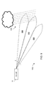
- FIG. 9 is a view of an aircraft mounted radar vertically sweeping across ground and weather conditions, according to an exemplary embodiment
- FIG. 10 is a graph of radar return power from the airplane of FIG. 9 , according to an exemplary embodiment
- FIG. 11 is a graph of processes phase generated from radar return from the airplane of FIG. 9 , including detected weather conditions, according to an exemplary embodiment
- FIG. 12 includes graphs showing elevation versus beam gain and elevation versus complex conjugate phase angle for exemplary returns associated with the system illustrated in FIG. 9 ;
- FIG. 13 is a graph showing the response from vertically sampled beams in a polar coordinate arrangement for the graphs illustrated in FIG. 12 ;
- FIG. 14 is a graph showing a focusing vector for the exemplary returns illustrated in FIG. 12 .
- the invention includes, but is not limited to a novel structural combination of conventional data/signal processing components and communications circuits, and not in the particular detailed configurations thereof. Accordingly, the structure, methods, functions, control and arrangement of conventional components software, and circuits have, for the most part, been illustrated in the drawings by readily understandable block representations and schematic diagrams, in order not to obscure the disclosure with structural details which will be readily apparent to those skilled in the art, having the benefit of the description herein. Further, the invention is not limited to the particular embodiments depicted in the exemplary diagrams, but should be construed in accordance with the language in the claims.
- Aircraft control center 10 includes flight displays 20 which are used to increase visual range and to enhance decision-making abilities.
- flight displays 20 may provide an output from a radar system of the aircraft.
- a radar system 102 is generally located inside nose 100 of the aircraft or inside a cockpit of the aircraft. According to other exemplary embodiments, radar system 102 may be located on the top of the aircraft or on the tail of the aircraft. Radar system 102 may include or be coupled to an antenna system.
- radar system 102 is shown in greater detail, according to an exemplary embodiment.
- Radar system 102 is coupled to an antenna 108 that includes a first portion 110 of the antenna and a second portion 112 of the antenna.
- Antenna 108 may receive radar returns from a target.
- the radar returns received by radar antenna 108 associated with radar system 102 can be separated into two or more portions 110 and 112 .
- First portion 110 of the returns may relate to data from one area, while second portion 112 of the returns may relate to a second area.
- second portion 112 may be a bottom half or top half of the antenna.
- second portion 112 may be any half of the antenna, or other sized portion of the antenna.
- first portion 110 can be the entire antenna or other sized portion.
- second portion 112 includes first portion 110 . Returns from first portion 110 are associated with a half aperture and returns from second portion 112 are associated with a full aperture.
- a high angle resolution process produces angles normal to the angle of separation between portions 110 and 112 .
- a full/half separation allows angle estimates to be made.
- a separation in azimuth allows high resolution in that azimuth direction according to another exemplary embodiment.
- a half aperture (or switched aperture) method may be used to sense terrain height.
- Radar system 102 of the aircraft may operate through radar antenna 108 that toggles between transmitting and receiving on the full aperture and transmitting on the full aperture while receiving on the half aperture.
- the received signals may be processed to determine a high resolution estimate of a target angle relative to the boresite of the antenna beam.
- the signals may be processed using a complex conjugate multiplication method to determine the target angle. The method is related to sequential lobing but is executed in the phase domain as opposed to the common amplitude domain.
- the method may be used in terrain altitude estimation systems.
- the method may be 10 to 15 times more accurate than methods commonly used in monopulse terrain following and terrain avoidance systems.
- the first and second portion may be a bottom half, a top half, a left half, a right half, or a whole of the antenna.
- the first portion may relate to transmitting on any fraction of the full aperture (sum) and the second portion may relate to a half aperture.
- the present invention is not limited to half aperture techniques and applies any technique that uses fractional apertures.
- the first portion may relate to a half aperture and the second portion may relate to a full aperture.
- both the first portion and second portion may be either a full aperture or half aperture. Any combination of the first portion and second portion that gives an apparent change in the phase center may be used.
- the first portion is preferably not identical to the second portion.
- the first portion can intersect, include, or be exclusive of the second portion.
- combinations of portions can use the reciprocal nature of the radar process of system 102 to exchange fractional aperture selection from transmit to receive operations.
- the received phase center is effectively moved. While one embodiment shows reception on a full aperture with a mixed transmission of full and half apertures, other sub-aperture selections on reception and transmission are possible.
- a first pulse may be provided before sampling the first returns associated with first portion 110 , and a second pulse may be provided before sampling the second returns associated with second portion 112 . This cycle of pulse and returns can be repeated.
- the first and second pulses can be full aperture pulses.
- the full aperture receive data may be used to allow full aperture and half aperture data to be separated.
- a full aperture coded pulse may be provided for the first data and a half aperture coded pulse may be provided for the second data.
- the first data and second data received may be associated with full aperture received data, according to an exemplary embodiment.
- a one third aperture may be used instead of a half aperture.
- a two thirds aperture may be used instead of a half aperture.
- the aperture may be separated in various ways other than a top half and a bottom half or a left half and a right half, and the aperture may be separated unevenly (e.g., not in two halves).
- Radar system 102 may include a receive circuit 114 or other circuit configured to receive first data from first portion 110 and second data from second portion 112 and to provide the data to processor 116 .
- the first data and second data are associated with the first and second portion, respectively, because the first data and second data are derived from returns received by the first and second portion, respectively.
- the first data and second data can be associated with the first and second portion, respectively, because the first data and second data are derived from returns associated with transmissions from the first and second portions, respectively.
- processor 116 can be any hardware and/or software processor or processing architecture capable of executing instructions and operating on data related to the radar returns.
- the first data and second data may be derived from coded radar pulse transmissions.
- coding is not required.
- one system may transmit on the sum and receive on the sum, followed by an independent transmit on the sum and receive on the half aperture, where the pulse sample time does not overlap. Therefore, coding is not required for the transmissions.
- the limited scan time may lead to overlapping of sampling the different portions of the aperture, therefore requiring the use of different coded transmissions.
- the radar system may include a processor 116 or other circuitry to estimate the angle to a target relative to the antenna steering angle (i.e., the angle within the beam to the target), using the returns from the first portion and returns from the second portion.
- a method 200 for estimating the angle to a target is shown, according to an exemplary embodiment.
- a first return vector from the target is received from the first portion 110 of the antenna (step 202 ) and a second return vector from the target is received from the second portion 112 of the antenna (step 204 ).
- the first and second phases are processed together by multiplying the first vector by the conjugate of the second vector.
- the phase of the conjugate product is determined as a result (step 206 ).
- the resultant phase of the conjugate multiplication process is used to determine the angle within the beam to the target (step 208 ).
- the determined angle may be representative of a phase associated with first portion 110 of the antenna and second portion 112 of the antenna.
- a third return vector from the target from first portion 110 of the antenna may be received. Additionally, a fourth return vector from the target from second portion 112 of the antenna may be received. An angle within the beam to the target may be calculated using the first return vector, second return vector, third return vector, and fourth return vector. A third pulse may be provided before sampling the third returns, and a fourth pulse may be provided before sampling the fourth returns.
- Pulse beam 300 illustrates a four pulse high resolution pattern. As discussed above, although half-aperture is described, other sub-aperture sizes are possible and such sizes can be on the receive or transmit side. According to other exemplary embodiments, a three pulse pattern may be used, or other configurations may be used.
- the system “shuts off” half of the aperture half of the time. The system may transmit on the sum (e.g., full aperture) and receive on the sum (pulse 302 , e.g., portion 110 ).
- the system may then transmit on the sum and receive on one-half of the aperture (pulse 304 , e.g., portion 112 ).
- the next pulse of the system may transmit on the sum and receive on the sum (pulse 306 , e.g., portion 110 ), followed by transmitting on the sum and receiving on one-half of the aperture (pulse 308 , e.g., portion 112 ).
- the one-half of the aperture being received on in pulses 304 and 308 are the same halves, according to an exemplary embodiment.
- An upper half, lower half, left half, or right half of the aperture may be chosen.
- phase center of the antenna changes.
- the phase center data may be processed and used to produce phase steering information for the radar system.
- FIG. 4 an illustration of the difference in phase center between a full aperture and half aperture is shown.
- the distance 408 from target 402 to the center of full aperture 404 is different than the distance 410 from target 402 to the phase center of half aperture 406 (the upper aperture).
- the distance difference produces a phase difference that may be measured to estimate the angle to the target relative to the antenna surface.
- Distance 412 shown added to distance 410 , represents the difference in distances 408 , 410 .
- Distance 412 is a vector that represents the phase difference used to estimate the angle to the target relative to the antenna surface.
- Method 500 of FIG. 5 illustrates a method of determining the angle.
- phase processing may be used to calculate the angle to a target relative to the antenna pointing angle or beam angle.
- the phase processing uses the first data and the second data obtained by sequential lobing in a half-aperture antenna radar system (e.g., radar system 102 ).
- a half-aperture antenna radar system e.g., radar system 102
- the system may provide angle estimates with standard deviations less than the beamwidth divided by fifty instead of the beamwidth divided by ten for monopulse systems.
- the standard deviations may be in the range of one hundredth to one hundred fortieth of a real beamwidth.
- the terrain or target angle estimation performed with better accuracy may allow the radar system to be defined with both good detection characteristics and low false alarm characteristics.
- sequential lobing two antennas that are close to the same place may be used, going back and forth between the two antennas.
- An amplitude signature or phase signature that varies between the two halves of the antennas may be used to obtain data about target position for detected targets (e.g., an object such as other aircraft, terrain, towers, etc.).
- Sequential lobing generally does not use phase comparisons with moving targets due to Doppler-induced phase changes that contaminate the phase center measurement.
- using a complex conjugate multiply method allows the Doppler-induced phase changes to be removed by cancellation. Therefore, a change in phase center between a sum beam and a half beam may be determined.
- FIG. 5 a flow diagram of a method 500 of finding a parameter to use to compute a target angle is shown, according to an exemplary embodiment.
- the first pulse is received (step 502 ).
- the system may transmit on the sum beam and receive on the sum beam.
- a power vector V S (for the sum beam) and an angle ⁇ is received.
- the nomenclature represents a voltage signal associated with the energy of the received return.
- the voltage signal is expressed as a vector and represents power associated with the radar return.
- V S is the magnitude of the vector while ⁇ is the argument or phase of the vector.
- the second pulse is received (step 504 ).
- the system may transmit on the sum beam and receive on the half aperture.
- a half aperture power vector V H is received (for the half-aperture or upper beam).
- Also received is the same arbitrary angle ⁇ of step 502 plus a change in the phase due to movements between the pulses (represented by the variable “PhiDoppler”) and a change in the phase due to the shift in the phase center (represented by the variable “PhiOffset”).
- the change in phase of PhiDoppler is caused by relative movement of the target between the pulses.
- the PhiOffset is the phase difference caused by the distance 412 in FIG. 4 .
- PhiOffset ( 1 2 * arc ⁇ ⁇ tan ⁇ ( P C ) ) .
- the PhiOffset value of the angle component may be used as a parameter for computing the angle to target relative to the antenna pointing angle (step 510 ).
- the output of the set of conjugate multiplications of step 510 produces a scaled version of the angle from the antenna pointing angle (the angle references to a vector normal to the surface of the antenna flat plate).
- the antenna pointing angle may be added to produce the angle to the target. If the antenna pointing angle is referenced to the local horizon (e.g., ground), the final angular value provided by method 500 is the angle within the beam to the target referenced to the local horizon.
- the resultant vector of the multiplications of step 508 is in a full rectangular form, which allows the vector to be in a usable form to allow coherent integration with similar vectors.
- Coherent integration is the addition of multiple vector estimates to produce a better final estimate.
- averaging is done incoherently, with the multiple angle arguments of a vector that represents target phrase being averaged.
- the averaging process produces a best-case reduction in the standard deviation of the resulting angle by the square root of the number of samples averaged.
- One advantage of the present method is that coherent integration is possible for the estimated angles instead which produces a best case reduction in the standard deviation of the estimated angle of N, where N is the number of samples coherently averaged together.
- Coherent integration provides an advantage is that the angle may be improved by the number of samples integrated.
- the removal of the Doppler induced phase allows the coherent integration to be possible. For example, for a pulse stream of 30 pulses in a three-pulse system, 10 independent vectors are formed using the equation for P C . Errors caused by noise are therefore reduced by a factor of up to 10 compared to a single estimate.
- Coherent integration may additionally allow for glint (e.g., angle noise) reduction.
- glint e.g., angle noise
- Radar can cause transmitter frequency changes to produce radar return samples that are relatively independent. Selecting the largest returns while changing transmitter frequencies allows targets with the smallest target glint to be selected.
- Coherently averaging the rectangular power squared terms that are a product of the half-aperture (or other) process reduces the influence of returns that are small and likely to have substantial glint. See, Skolnik, Introduction to Radar Systems (McGraw Hill Book Company, New York, 1980, 2 nd edition).
- a two pulse version of method 500 of FIG. 5 requires a Doppler estimate to be available to produce pointing angle estimates within the radar beam, as the Doppler produces an angle error.
- the Doppler estimate may be obtained from either the radar of the aircraft or from other aircraft equipment.
- the Doppler estimate may be determined in a variety of ways (e.g., using data regarding the velocity of the aircraft, heading of the aircraft, scan angle of the aircraft, from a system such as a global positioning system (GPS) or otherwise, etc.).
- the equation for P D represents one method of generating a Doppler estimate from the radar in a method compatible with the less than full aperture process.
- Method 600 is a four pulse pattern process instead of the three pulse patterns process of method 500 of FIG. 5 .
- the system may transmit on the sum beam and receive on the sum beam (step 602 ), followed by transmitting on the sum beam and receiving on the half aperture (step 604 ), followed by transmitting on the sum beam and receiving on the sum beam (step 606 ) and followed by transmitting on the sum beam and receiving on the half sum beam (step 608 ).
- steps 602 - 608 equations may be formed as described in steps 502 - 506 of method 500 of FIG. 5 .
- complex conjugate processing may be performed (step 610 ) as described in step 508 of method 500 of FIG. 5 , and a parameter to use to compute the angle to target relative to the antenna pointing angle is found (step 612 ), as described in step 510 of method 500 of FIG. 5 .
- the fourth pulse may be similar to the second pulse, except the Doppler continues to rotate.
- the change in phase due to the Doppler may be tripled compared to the change in the second pulse of step 504 .
- the four pulses of steps 602 - 608 may be closely spaced such that high correlation between the pulse returns is maintained.
- the transmitting function may be toggled between a half aperture (or other fraction) and full aperture instead of the receive function.
- the system may transmit on the sum beam (step 502 ), followed by a transmit on the half aperture (step 504 ), and a transmit on the sum beam (step 506 ), while the system receives on the sum beam in all three pulses.
- data associated with the pulses can be sets of data associate with pulses.
- a flow diagram of a method 700 of applying a three pulse pattern to a radar e.g., a weather radar such as a MultiScan® wxr-2400 radar system as manufactured by Rockwell Collins, Inc.
- the system may transmit on the sum (step 702 ), transmit on the half aperture (step 704 ), and transmit on the sum (step 706 ).
- the three pulse lengths may be 25 microseconds long, according to one exemplary embodiment.
- the system may receive on the sum (step 708 ).
- the receive information is convolved with the three pulse codes in parallel to recover the three individual responses to the three pulses.
- the antenna pointing is approximately the same for all three pulses, and the radar target will not decorrelate over the time period (e.g., 75 microseconds) across the transmit set.
- the target angle may be calculated using the data received (step 710 ). The calculations may be similar to those of steps 510 and 512 of method 500 of FIG. 5 .
- a flow diagram of a method 800 of half aperture usage in a radar is illustrated, according to an exemplary embodiment.
- a two pulse pattern may be used instead of the three pulse pattern of method 700 of FIG. 7 .
- Method 800 may be used in cases where the Doppler is known and only two pulses are needed to calculate the angle to target.
- the system may transmit on the sum (step 802 ) and transmit on the half aperture (step 804 ) before receiving on the sum (step 806 ).
- phase code or frequency code For each transmission and reception (e.g., the two pulses in method 800 ), there is a phase code or frequency code.
- the codes or frequencies can be chosen to produce low cross-correlations between codes or frequencies. If the time between the two transmissions is short, the cross correlation between the codes is low. Therefore, separate sum and half aperture responses may be generated (step 808 ) from the response of step 806 .
- the received response of step 806 may be processed with two separate codes allowing responses from the half aperture and full aperture to be distinguished and separated.
- the analysis as described in FIG. 8 may then be used to compute an angle to target relative to the antenna pointing angle (step 810 ). The calculations may be similar to those of steps 508 and 510 of method 500 of FIG. 5 .
- the use of a target phase in a radar process allows the ability to avoid a lengthy filtering process that is used to produce estimates of power return between antenna sweeps taken at different elevations when target elevation is used to separate targets, such as weather from ground.
- the two pulses may be used to make an angle measurement in flight as the pulses are correlated.
- the less than full aperture method as disclosed may be used for the detection of a plurality of targets.
- Land, terrain, other aircraft, military targets, towers, etc. may be objects that may be detected.
- the less than full aperture method may be used to detect the top of radio towers.
- the less than full aperture method may be used to detect the top of precipitation as well.
- FIG. 9 an illustration of an aircraft 10 and vertical sweeping is shown, according to an exemplary embodiment.
- weather conditions 900 is illustrated as precipitation and terrain 902 is shown.
- Vertical sweeping may be used in conjunction with coherent integration.
- An antenna may vertically sweep (e.g., sweep from low to high) and the conjugate products (as determined using method 500 of FIG. 5 ) across the beam may be averaged. The averaging may be done either with or without focusing. Without focusing, the complex conjugate products are added. With focusing, the complex conjugate products are compensated by phase change over the beam by multiplying each complex conjugate by a local unit vector representing the phase of the antenna conjugate process at the approximate antenna sample angles. Focusing is discussed in more detail below with reference to FIGS. 12-14 .
- a small number of three pulse sets may have a common transmit frequency, followed by changing the transmit frequency (i.e., by more than a value of 1 over the pulse length) and sampling a next block of returns.
- the terms produced by the conjugate process may be coherently summed.
- Aircraft 10 may sweep vertically in a range from area 904 to area 908 .
- the radar detects ground objects.
- weather targets may begin to be detected. Detected ground targets occupy high gain locations in the beam compared to the weather targets, which occupy very low gain locations. Angle data from these areas 904 , 906 is generally dominated by the phase response from ground targets.
- ground targets begin to drop in return levels while weather targets produce larger returns. Therefore, generally data from area 908 is “contaminated” by weather targets and is generally not useful for ground target estimation.
- the radar system of aircraft 10 may include a processor or other processing devices and/or software that is configured to detect when weather conditions are picked up on the radar returns. Further, the radar system may include the same to remove or discard radar returns affected by the weather conditions. The radar system may then use valid radar returns to determine the angle within the beam to the terrain using the systems and methods as described in the disclosure.
- lower one-half beam data may be used to reject weather induced errors that may be the result of vertically sweeping from area 904 to area 908 .
- Data may be integrated together over the lower half of the beam response from ground.
- the point at which data is no longer used may be determined by an angle constraint (e.g., one-half beam width from where “good” data was last seen by the radar).
- a maximum power point may be determined and used determine when no longer to use the data.
- FIG. 10 a graph 1000 illustrating vertical sweeping is shown, according to an exemplary embodiment.
- the horizontal axis represents tilt angle of the antenna and the vertical axis represents the range.
- Ground is represented in areas 1002 - 1011 while there are no returns in the other areas of graph 1000 .
- Areas 1002 - 1011 are shown broken into sections based on the phase output from the complex conjugate method given the tilt angle and range of the antenna. The difference between areas 1002 - 1011 may be representative of the phase shift as the antenna tilt angle changes.
- graph 1100 illustrates the addition of weather interference (e.g., rain).
- graph 1100 illustrates additional returns (in areas 1110 - 1114 ) which are picked up due to the presence of weather conditions, in addition to areas 1102 - 1108 .
- the maximum height where precipitation is detected is in area 1112 (e.g., where the values range from ⁇ 40 to ⁇ 80).
- power levels drop as the antenna is scanned above the ground.
- the power returns from the precipitation override the fading ground returns as the antenna is scanned past the ground.
- radar returns may be rejected out when the antenna is pointed in area 908 of FIG. 9 (e.g., the returns when the tilt angle is greater than 0 as shown in FIG. 11 are rejected). Radar returns from weather will generally fall from some altitude to the surface of Earth.
- the radar may be optimized to detect obstacles such as towers in addition to terrain or ground and weather conditions such as rain. Processing for determining obstacles may be separated from processing for determining terrain. Weather may be separated from terrain as described in FIG. 9 , while using shorter transmitter pulses may allow for obstacles to stand out and be separated from weather conditions.
- system 102 may detect errors as a self-monitoring system.
- Response data may be used for self-monitoring.
- the known amplitude characteristic difference between a full aperture and half aperture may be used to confirm the operation of the radar.
- a constant phase slope as illustrated in graphs 1000 , 1100 of FIGS. 10-11 may be used to monitor operations.
- System 102 may detect a change in power in the data.
- the process flows of FIGS. 2C , 5 , 6 , 7 , and 8 may be embodied as hardware and/or software.
- the processes may be executed as computer code on any processing or hardware architecture or in any radar system.
- FIG. 12 shows a first graph of elevation being swept on the Y axis versus a beam gain on the X axis and a second graph showing elevation being swept on the Y axis versus phase output from the conjugate process on the X axis.
- FIG. 12 shows a relatively linear relationship between the complex conjugate phase output and the elevation angle.
- FIG. 13 shows individual vectors V 1 through V n representing responses from vertically sampled beams in a polar coordinate arrangement. The vertically sampled beams can correspond to the beam set shown in FIG. 9 .
- a focusing vector is shown in polar coordinates.
- System 102 can be optimized by using a focusing vector.
- the samples may be averaged together as given by the equation below. If the beam is slewing vertically during the sample time, the local antenna elevation angle is included.
- the equation can be organized with a fixed elevation angle, e.g., the center angle of the sample set, and an offset to that angle to represent that set of elevation angles as given by the equation below:
- phase arguments are averaged, that is the individual samples are incoherently averaged to gain a better estimate of the switched antenna/conjugate processed angle which gives a better estimate of the angle to the target. If coherent processes for the inbeam phase estimate are used, the coherently averaged in beam phase can be generally represented by the following equation:
- the coherently average samples are achieved, better estimates can be achieved than from an incoherently filtered system.
- the standard deviation of a set of vectors coherently averaged is reduced by the number of elements averaged together as opposed to a square root improvement in standard deviation which incoherent integration (straight averaging) affords. Accordingly, an estimate of target angle can be coherently built according to the equation below (first separating the summations).
- a goal of gaining reductions in the standard deviation of the target estimate by about n (number of samples) can be achieved.
- the goal can be achieved by addressing the problem that the Vc vector moves over about +90 to ⁇ 90 degrees while the target is in view of the beam. Adding samples associated with the extremes of +90 and ⁇ 90 degrees does not produce the constructive addition, but instead a destructive addition that tends to cancel.
- the high signal-to-noise movement of the Vc vector over the scan with the elevation offset from the center of the set of samples for each sample can be described by the equation below.
- K1 is the beam scaling constant introduced in the equation set forth above.
- ⁇ VcCausedByElevMovement n K ⁇ ElevOffsetFromCenter n
- ⁇ n exp( K 2 ⁇ j ⁇ VcCausedByElevMovement n ) (exp(x) is an epsilon to the x power function)
- each unit vector ⁇ n may have the opposite local movement of the local Vc vector. This allows all the Vc vectors to be aligned according to the following equation:
- the Vc vectors are focused to be in alignment and coherently integrated.
Abstract
Description
P2=(V H,∠(φ+PhiDoppler+PhiOffset)).
The PhiOffset is the phase difference caused by the
P A =P1*conj(P2)=(|V S |*|V H|,∠(−PhiDoppler−PhiOffset)).
φInBeam =K1·arg(Vc)
where Vc is the output of the three pulse conjugate process, K1 is a factor relating the output of the conjugate process with the angle within the beam, and the term “arg(Vc)” refers to the phase of the vector Vc is in polar form.
The angle to the target is the beam elevation plus the angle within the beam as given by the equation below:
φTgt=Elevation+φInBeam
where Vc is a rectangular complex output from the switched antenna/conjugate process. This compares to the incoherently filtered type of process discussed above and is represented by the following equation:
φVcCausedByElevMovement
μn=exp(K2·j·π·φ VcCausedByElevMovement
(exp(x) is an epsilon to the x power function)
Claims (20)
Priority Applications (1)
| Application Number | Priority Date | Filing Date | Title |
|---|---|---|---|
| US13/474,559 US8773301B1 (en) | 2008-07-02 | 2012-05-17 | System for and method of sequential lobing using less than full aperture antenna techniques |
Applications Claiming Priority (2)
| Application Number | Priority Date | Filing Date | Title |
|---|---|---|---|
| US12/167,203 US8558731B1 (en) | 2008-07-02 | 2008-07-02 | System for and method of sequential lobing using less than full aperture antenna techniques |
| US13/474,559 US8773301B1 (en) | 2008-07-02 | 2012-05-17 | System for and method of sequential lobing using less than full aperture antenna techniques |
Related Parent Applications (1)
| Application Number | Title | Priority Date | Filing Date |
|---|---|---|---|
| US12/167,203 Continuation US8558731B1 (en) | 2008-07-02 | 2008-07-02 | System for and method of sequential lobing using less than full aperture antenna techniques |
Publications (1)
| Publication Number | Publication Date |
|---|---|
| US8773301B1 true US8773301B1 (en) | 2014-07-08 |
Family
ID=49321494
Family Applications (2)
| Application Number | Title | Priority Date | Filing Date |
|---|---|---|---|
| US12/167,203 Active 2030-12-23 US8558731B1 (en) | 2008-07-02 | 2008-07-02 | System for and method of sequential lobing using less than full aperture antenna techniques |
| US13/474,559 Active US8773301B1 (en) | 2008-07-02 | 2012-05-17 | System for and method of sequential lobing using less than full aperture antenna techniques |
Family Applications Before (1)
| Application Number | Title | Priority Date | Filing Date |
|---|---|---|---|
| US12/167,203 Active 2030-12-23 US8558731B1 (en) | 2008-07-02 | 2008-07-02 | System for and method of sequential lobing using less than full aperture antenna techniques |
Country Status (1)
| Country | Link |
|---|---|
| US (2) | US8558731B1 (en) |
Cited By (8)
| Publication number | Priority date | Publication date | Assignee | Title |
|---|---|---|---|---|
| US9733349B1 (en) | 2007-09-06 | 2017-08-15 | Rockwell Collins, Inc. | System for and method of radar data processing for low visibility landing applications |
| US20170285137A1 (en) * | 2016-04-01 | 2017-10-05 | Rockwell Collins, Inc. | Beam sharpening radar system and method |
| US9939526B2 (en) | 2007-09-06 | 2018-04-10 | Rockwell Collins, Inc. | Display system and method using weather radar sensing |
| US10228460B1 (en) | 2016-05-26 | 2019-03-12 | Rockwell Collins, Inc. | Weather radar enabled low visibility operation system and method |
| US10353068B1 (en) | 2016-07-28 | 2019-07-16 | Rockwell Collins, Inc. | Weather radar enabled offshore operation system and method |
| US10705201B1 (en) | 2015-08-31 | 2020-07-07 | Rockwell Collins, Inc. | Radar beam sharpening system and method |
| US10928510B1 (en) | 2014-09-10 | 2021-02-23 | Rockwell Collins, Inc. | System for and method of image processing for low visibility landing applications |
| WO2021133380A1 (en) * | 2019-12-23 | 2021-07-01 | A^3 By Airbus, Llc | Systems and methods for noise compensation of radar signals |
Families Citing this family (6)
| Publication number | Priority date | Publication date | Assignee | Title |
|---|---|---|---|---|
| US9354633B1 (en) | 2008-10-31 | 2016-05-31 | Rockwell Collins, Inc. | System and method for ground navigation |
| US9262932B1 (en) | 2013-04-05 | 2016-02-16 | Rockwell Collins, Inc. | Extended runway centerline systems and methods |
| US9477865B2 (en) * | 2013-12-13 | 2016-10-25 | Symbol Technologies, Llc | System for and method of accurately determining true bearings of radio frequency identification (RFID) tags associated with items in a controlled area |
| US9755294B2 (en) | 2014-07-07 | 2017-09-05 | Symbol Technologies, Llc | Accurately estimating true bearings of radio frequency identification (RFID) tags associated with items located in a controlled area |
| US9773136B2 (en) | 2015-10-19 | 2017-09-26 | Symbol Technologies, Llc | System for, and method of, accurately and rapidly determining, in real-time, true bearings of radio frequency identification (RFID) tags associated with items in a controlled area |
| US10726218B2 (en) | 2017-07-27 | 2020-07-28 | Symbol Technologies, Llc | Method and apparatus for radio frequency identification (RFID) tag bearing estimation |
Citations (232)
| Publication number | Priority date | Publication date | Assignee | Title |
|---|---|---|---|---|
| US2416155A (en) * | 1943-03-27 | 1947-02-18 | Westinghouse Electric Corp | Position locator |
| US2929059A (en) | 1955-03-14 | 1960-03-15 | Decca Record Co Ltd | Radio antennae systems |
| US2930035A (en) | 1954-07-12 | 1960-03-22 | Goodyear Aircraft Corp | Terrain clearance control apparatus |
| US2948892A (en) | 1949-09-28 | 1960-08-09 | Cutler Hammer Inc | Precision indicating radar system |
| US2965894A (en) | 1956-12-26 | 1960-12-20 | Bell Telephone Labor Inc | Altitude control system |
| US2994966A (en) | 1957-03-13 | 1961-08-08 | Sperry Rand Corp | System for predicting radar terrain reflection |
| US3031660A (en) | 1956-06-22 | 1962-04-24 | Robert E Young | Plan position indicator with elevation indication in color |
| US3049702A (en) | 1958-05-15 | 1962-08-14 | Sperry Rand Corp | Single target height indicator |
| US3064252A (en) | 1952-03-31 | 1962-11-13 | Arthur A Varela | Height finding radar system |
| US3070795A (en) | 1954-01-25 | 1962-12-25 | Torrence H Chambers | Elevation angle computer for stacked beam height finding radar system |
| US3072903A (en) | 1953-06-22 | 1963-01-08 | Lab For Electronics Inc | Signal switching apparatus |
| US3107351A (en) * | 1955-04-29 | 1963-10-15 | Robert A Milam | Radar resolutions |
| US3113310A (en) | 1961-02-10 | 1963-12-03 | Avco Corp | Null scanning radar |
| US3129425A (en) * | 1957-09-27 | 1964-04-14 | Westinghouse Electric Corp | Three beam monopulse radar system and apparatus |
| US3153234A (en) | 1958-12-17 | 1964-10-13 | Robert H Begeman | Fixed antenna terrain clearance system |
| US3175215A (en) * | 1954-09-08 | 1965-03-23 | Hughes Aircraft Co | Single channel monopulse radar system |
| US3212088A (en) | 1960-12-21 | 1965-10-12 | Ibm | Radar display system |
| US3221328A (en) * | 1961-12-01 | 1965-11-30 | Siemens Ag Albis | Sum-difference direction-finding device |
| US3241141A (en) | 1957-11-21 | 1966-03-15 | North American Aviation Inc | Terrain viewing radar system |
| US3274593A (en) | 1953-03-26 | 1966-09-20 | Arthur A Varela | Height finding radar system |
| US3325807A (en) | 1957-12-20 | 1967-06-13 | North American Aviation Inc | Ground clearance warning system |
| US3339199A (en) * | 1964-12-24 | 1967-08-29 | Thomson Houston Comp Francaise | Single-channel signal-processing network and monopulse receiver systems embodying the same |
| US3397397A (en) | 1966-12-20 | 1968-08-13 | Texas Instruments Inc | Terrain-following radar |
| US3448450A (en) | 1966-09-01 | 1969-06-03 | Thomson Houston Comp Francaise | Pulse radar for determining angles of elevation |
| US3618090A (en) | 1960-04-05 | 1971-11-02 | Us Navy | Radar |
| US3680094A (en) | 1966-04-04 | 1972-07-25 | North American Aviation Inc | Terrain-warning radar system |
| US3739380A (en) | 1960-04-04 | 1973-06-12 | North American Aviation Inc | Slant range tracking terrain avoidance system |
| US3781878A (en) | 1971-07-29 | 1973-12-25 | G Kirkpatrick | Means for suppressing ground clutter in airborne radar |
| US3810175A (en) | 1972-01-17 | 1974-05-07 | Hughes Aircraft Co | Along track terrain avoidance contouring system |
| US3815132A (en) | 1960-06-03 | 1974-06-04 | Rockwell International Corp | Radar for automatic terrain avoidance |
| US3885237A (en) | 1971-07-29 | 1975-05-20 | George M Kirkpatrick | Phased array sequential switching between short and long distance targets |
| US3956749A (en) | 1973-04-16 | 1976-05-11 | The United States Of America As Represented By The Secretary Of The Navy | Bearing measurement device for a portable attack warning radar |
| US4024537A (en) | 1976-05-24 | 1977-05-17 | Hart Gerald E | Doppler-radar, projected terrain-clearance system |
| US4058701A (en) | 1974-05-14 | 1977-11-15 | Schoeller & Co. Elektrotechnische Fabrik Gmbh & Co. | Glow element arrangement for electric cigarette lighters |
| US4058710A (en) | 1975-03-14 | 1977-11-15 | Dornier Gmbh. | Process for preventing undesired contact with land or water by low-flying aircraft |
| US4277845A (en) | 1977-07-29 | 1981-07-07 | Rockwell International Corporation | Meteor scatter burst communication system |
| US4435707A (en) | 1981-03-09 | 1984-03-06 | Sperry Corporation | Weather radar with signal compensation for precipitation |
| US4481519A (en) | 1981-11-05 | 1984-11-06 | Raytheon Company | Radio frequency signal direction finding apparatus |
| US4532515A (en) | 1982-02-10 | 1985-07-30 | Cantrell Ben H | Angle of arrival measurements for two unresolved sources |
| US4628318A (en) | 1983-12-02 | 1986-12-09 | Rockwell International Corporation | Ground clutter suppression technique |
| US4646244A (en) | 1984-02-02 | 1987-02-24 | Sundstrand Data Control, Inc. | Terrain advisory system |
| US4649388A (en) | 1985-11-08 | 1987-03-10 | David Atlas | Radar detection of hazardous small scale weather disturbances |
| US4685149A (en) | 1977-07-29 | 1987-08-04 | Rockwell International Corporation | Meteor scatter burst communication system |
| US4760396A (en) | 1986-07-11 | 1988-07-26 | Merit Technology Incorporated | Apparatus and method for adjusting set clearance altitude in a terrain following radar system |
| US4843398A (en) | 1979-08-07 | 1989-06-27 | The Marconi Company Limited | Tracking radar system |
| US4924401A (en) | 1987-10-30 | 1990-05-08 | The United States Of America As Represented By The Secretary Of The Air Force | Aircraft ground collision avoidance and autorecovery systems device |
| US4939513A (en) | 1983-05-13 | 1990-07-03 | Sundstrand Data Control, Inc. | System for alerting a pilot of a dangerous flight profile during low level maneuvering |
| US4951059A (en) | 1988-11-02 | 1990-08-21 | Westinghouse Electric Corp. | Dual stacked beam radar |
| US4953972A (en) | 1988-12-27 | 1990-09-04 | Environmental Research Institute Of Michigan | Range dispersion sensor |
| US4965573A (en) | 1988-10-03 | 1990-10-23 | Delco Electronics Corporation | Forward looking windshear detection system |
| US5047781A (en) | 1968-06-05 | 1991-09-10 | Hughes Aircraft Company | Radar sensing generator in a monopulse radar system |
| US5049886A (en) | 1990-09-26 | 1991-09-17 | Rockwell International Corporation | Weather radar system with improved display characteristics |
| US5173703A (en) | 1980-12-29 | 1992-12-22 | Raytheon Company | All weather strike system (AWTSS) and method of operation |
| US5175554A (en) | 1980-12-29 | 1992-12-29 | Raytheon Company | All weather tactical strike system (AWTSS) and method of operation |
| US5198819A (en) | 1992-03-02 | 1993-03-30 | Thermwood Corporation | Weather radar display system |
| US5247303A (en) | 1992-07-20 | 1993-09-21 | University Corporation For Atmospheric Research | Data quality and ambiguity resolution in a doppler radar system |
| US5311183A (en) | 1991-06-13 | 1994-05-10 | Westinghouse Electric Corp. | Windshear radar system with upper and lower elevation radar scans |
| US5332998A (en) | 1992-04-30 | 1994-07-26 | Thomson-Csf | Procedure for detection and localization of objects on relatively flat ground and a device for application of the procedure |
| US5345241A (en) | 1992-12-07 | 1994-09-06 | Litton Systems, Inc. | Self-contained method for correction of an inertial system over a body of water |
| US5539409A (en) | 1994-06-30 | 1996-07-23 | Westinghouse Electric Corp. | Apparatus and method for windshear data processing |
| US5559515A (en) | 1981-11-27 | 1996-09-24 | Northrop Grumman Norden Systems | Channel switching interferometric AMTI radar |
| US5559518A (en) | 1981-11-27 | 1996-09-24 | Northrop Grumman Corporation | Low target velocity interferometric AMTI radar |
| US5592178A (en) | 1994-06-01 | 1997-01-07 | Raytheon Company | Wideband interference suppressor in a phased array radar |
| US5820080A (en) | 1996-03-14 | 1998-10-13 | Trimble Navigation Limited | Precision equivalent landing system using gps and an altimeter |
| US5831570A (en) | 1996-05-14 | 1998-11-03 | Alliedsignal, Inc. | Radar resolution using monopulse beam sharpening |
| US5867119A (en) | 1997-10-02 | 1999-02-02 | Mcdonnell Douglas Corporation | Precision height measuring device |
| US5894286A (en) * | 1986-04-23 | 1999-04-13 | Dassault Electronique | Interferometric receiver for electromagnetic signals |
| US5920276A (en) | 1996-03-11 | 1999-07-06 | Imaging Accessories, Inc. | Automatic horizontal and vertical scanning radar with terrain display |
| US5923279A (en) | 1997-02-17 | 1999-07-13 | Deutsches Zentrum Fur Luft-Und Raumfahrt E.V. | Method of correcting an object-dependent spectral shift in radar interferograms |
| US5936575A (en) * | 1998-02-13 | 1999-08-10 | Science And Applied Technology, Inc. | Apparatus and method for determining angles-of-arrival and polarization of incoming RF signals |
| US5982320A (en) * | 1986-11-28 | 1999-11-09 | The Marconi Company Limited | Radar seeker |
| US6023240A (en) | 1999-05-17 | 2000-02-08 | Rockwell Collins, Inc. | Method for determining a phase measurement error map using rotating antenna information |
| US6061022A (en) * | 1999-06-04 | 2000-05-09 | Itt Manufacturing Enterprises, Inc. | Azimuth and elevation direction finding system based on hybrid amplitude/phase comparison |
| US6064942A (en) | 1997-05-30 | 2000-05-16 | Rockwell Collins, Inc. | Enhanced precision forward observation system and method |
| US6075484A (en) * | 1999-05-03 | 2000-06-13 | Motorola, Inc. | Method and apparatus for robust estimation of directions of arrival for antenna arrays |
| US6128553A (en) | 1998-07-24 | 2000-10-03 | Rockwell Collins, Inc. | Menu control knob |
| US6150901A (en) | 1998-11-20 | 2000-11-21 | Rockwell Collins, Inc. | Programmable RF/IF bandpass filter utilizing MEM devices |
| US6154169A (en) | 1998-07-06 | 2000-11-28 | Allied Signal | Scan management and automatic tilt control for airborne radars |
| US6154151A (en) | 1998-06-16 | 2000-11-28 | Rockwell Collins, Inc. | Integrated vertical situation display for aircraft |
| US6157891A (en) | 1998-11-16 | 2000-12-05 | Lin; Ching-Fang | Positioning and ground proximity warning method and system thereof for vehicle |
| US6157339A (en) * | 1998-07-07 | 2000-12-05 | Nec Corporation | Radar for enabling accurate determination of false image of target |
| US6163021A (en) | 1998-12-15 | 2000-12-19 | Rockwell Collins, Inc. | Navigation system for spinning projectiles |
| US6166661A (en) | 1999-01-22 | 2000-12-26 | Rockwell Collins, Inc. | System for detecting ice on an aircraft |
| US6169770B1 (en) | 1998-01-08 | 2001-01-02 | Rockwell Collins, Inc. | Preemptive processor for mode S squitter message reception |
| US6178391B1 (en) | 1998-04-15 | 2001-01-23 | Rockwell Collins, Inc. | Method for partitioning an integrated ground air traffic management communications system |
| US6184816B1 (en) | 1998-07-06 | 2001-02-06 | Alliedsignal Inc. | Apparatus and method for determining wind profiles and for predicting clear air turbulence |
| US6188330B1 (en) | 1999-02-01 | 2001-02-13 | Alliedsignal, Inc. | Windshear detection system |
| US6194980B1 (en) | 1999-05-19 | 2001-02-27 | Rockwell Collins, Inc. | Quadrature hybrid RF combining system |
| US6201494B1 (en) | 1999-07-30 | 2001-03-13 | Rockwell Collins, Inc. | Automatic storm finding weather radar |
| US6204806B1 (en) | 1999-02-26 | 2001-03-20 | Rockwell Collins, Inc. | Method of enhancing receiver autonomous GPS navigation integrity monitoring and GPS receiver implementing the same |
| US6208284B1 (en) | 1998-06-16 | 2001-03-27 | Rockwell Science Center, Inc. | Radar augmented TCAS |
| US6236351B1 (en) | 1998-07-06 | 2001-05-22 | Alliedsignal Inc. | Method and apparatus for implementing automatic tilt control of a radar antenna on an aircraft |
| US6259400B1 (en) | 2000-03-15 | 2001-07-10 | Rockwell Collins, Inc. | Fast acquisition of GPS signal corrupted by doppler or time delay effects |
| US6266114B1 (en) | 1999-07-14 | 2001-07-24 | Rockwell Collins, Inc. | Method and apparatus for compensating a liquid crystal display |
| US6281832B1 (en) | 1999-08-31 | 2001-08-28 | Rockwell Collins | Method and apparatus for using statistical data processing in altimeter and terrain awareness integrity monitoring systems |
| US6285926B1 (en) | 2000-04-28 | 2001-09-04 | Rockwell Collins | Selected hover altitude deviation display and method |
| US6285298B1 (en) | 2000-02-24 | 2001-09-04 | Rockwell Collins | Safety critical system with a common sensor detector |
| US6285337B1 (en) | 2000-09-05 | 2001-09-04 | Rockwell Collins | Ferroelectric based method and system for electronically steering an antenna |
| US6317872B1 (en) | 1997-07-11 | 2001-11-13 | Rockwell Collins, Inc. | Real time processor optimized for executing JAVA programs |
| US6340946B1 (en) | 2000-08-03 | 2002-01-22 | Massachusetts Institue Of Technology | Method for determining storm predictability |
| US6345127B1 (en) | 1999-02-26 | 2002-02-05 | Rockwell Collins, Inc. | Video data compression preprocessor using holographic optical correlation and feedback |
| US6359585B1 (en) | 2000-05-22 | 2002-03-19 | Rockwell Collins, Inc. | Apparatus and method of determining an orientation of a GPS receiver |
| US6373418B1 (en) | 2000-05-25 | 2002-04-16 | Rockwell Collins, Inc. | Nyquist response restoring delta-sigma modulator based analog to digital and digital to analog conversion |
| US6374286B1 (en) | 1998-04-06 | 2002-04-16 | Rockwell Collins, Inc. | Real time processor capable of concurrently running multiple independent JAVA machines |
| US6377202B1 (en) | 2000-03-24 | 2002-04-23 | The United States Of America As Represented By The Secretary Of Commerce | Icing hazard avoidance system and method using dual-polarization airborne radar |
| US6377892B1 (en) | 2000-05-02 | 2002-04-23 | Rockwell Collins, Inc. | Integrated navigation system |
| US6388607B1 (en) | 2000-09-22 | 2002-05-14 | Rockwell Collins, Inc. | Multi-sweep method and system for mapping terrain with a weather radar system |
| US6388608B1 (en) | 2000-09-22 | 2002-05-14 | Rockwell Collins, Inc. | Method and system for detecting turbulence with reduced errors resulting from vertical shear components |
| US6421000B1 (en) | 2000-06-08 | 2002-07-16 | Rockwell Collins, Inc. | GPS multipath mitigation using a multi-element antenna array |
| US6424288B1 (en) | 2000-09-22 | 2002-07-23 | Rockwell Collins, Inc. | Multi-sweep method and system for detecting and displaying weather information on a weather radar system |
| US6426720B1 (en) | 1998-03-03 | 2002-07-30 | General Electric Company | System and method for directing an adaptive antenna array |
| US6426717B1 (en) | 2001-05-11 | 2002-07-30 | Rockwell Collins, Inc. | Single antenna FM radio altimeter operating in a continuous wave mode and an interrupted continuous wave mode |
| US6441773B1 (en) | 2000-08-24 | 2002-08-27 | Rockwell Collins, Inc. | Weather radar system integrating ground-based weather radar with on-board aircraft weather radar |
| US6448922B1 (en) | 2000-08-24 | 2002-09-10 | Rockwell Collins, Inc. | Retrofit solution for the integration of ground-based weather radar images with on-board weather radar |
| US6452511B1 (en) | 2001-08-08 | 2002-09-17 | Rockwell Collins, Inc. | Method and system for providing ground proximity warnings |
| US6456236B1 (en) | 2001-04-24 | 2002-09-24 | Rockwell Collins, Inc. | Ferroelectric/paraelectric/composite material loaded phased array network |
| US6456238B1 (en) | 2001-05-15 | 2002-09-24 | Raytheon Company | Dynamic signal routing in electronically scanned antenna systems |
| US6462703B2 (en) | 2000-07-27 | 2002-10-08 | Innovative Solutions & Support, Inc. | Method and system for high precision altitude measurement over hostile terrain |
| US6473026B1 (en) | 1998-01-23 | 2002-10-29 | Centre National De La Recherche Scientifique (Cnrs) | Technique for estimating rainfall from a meteorological radar with polarization diversity |
| US6473240B1 (en) | 2000-09-19 | 2002-10-29 | Rockwell Collins | Apparatus and method for using orthogonally polarized light in projection cockpit displays |
| US6473037B2 (en) | 2000-12-12 | 2002-10-29 | Harris Corporation | Phased array antenna system having prioritized beam command and data transfer and related methods |
| US6492934B1 (en) | 2001-08-06 | 2002-12-10 | Rockwell Collins | Method of deriving ground speed for descending aircraft |
| US6512476B1 (en) | 2001-06-21 | 2003-01-28 | Rockwell Collins, Inc. | Adaptive radar scanning system |
| US6520056B1 (en) | 1999-08-26 | 2003-02-18 | Rockwell Collins, Inc. | Method and apparatus for cutting optical films having precision alignment of optical axes with optical film edges |
| US6525674B1 (en) | 2001-08-08 | 2003-02-25 | Rockwell Collins, Inc. | Conditional hazard alerting display |
| US6531669B1 (en) | 2001-05-02 | 2003-03-11 | Rockwell Collins, Inc. | Method and system for illuminating a mechanical rotary push-button switch |
| US6549161B1 (en) | 2001-06-21 | 2003-04-15 | Rockwell Collins, Inc. | Multiple altitude radar system |
| US6567728B1 (en) | 2001-08-08 | 2003-05-20 | Rockwell Collins, Inc. | Terrain awareness system having nuisance alarm filter for use during approach |
| US6574030B1 (en) | 2001-05-18 | 2003-06-03 | Rockwell Collins, Inc. | Multi-mode display using an electronically controlled mirror |
| US6577947B1 (en) | 2002-03-01 | 2003-06-10 | Rockwell Collins, Inc. | Method and apparatus for identification of hazards along an intended travel route |
| US6590528B1 (en) | 2001-12-05 | 2003-07-08 | Rockwell Collins, Inc. | Low cost interference reduction system for GPS receivers |
| US6600443B2 (en) * | 2000-06-05 | 2003-07-29 | Tc (Bermuda) License, Ltd. | Method and apparatus to determine the direction to a transponder in a modulated backscatter communication system |
| US6603425B1 (en) | 2000-09-22 | 2003-08-05 | Rockwell Collins, Inc. | Method and system for suppressing ground clutter returns on an airborne weather radar |
| US20030160718A1 (en) | 2002-02-27 | 2003-08-28 | Hitachi, Ltd. | Monopulse radar system |
| US6650291B1 (en) | 2002-05-08 | 2003-11-18 | Rockwell Collins, Inc. | Multiband phased array antenna utilizing a unit cell |
| US6650275B1 (en) | 2001-09-17 | 2003-11-18 | Rockwell Collins, Inc. | Image processing for hazard recognition in on-board weather radar |
| US6690299B1 (en) | 1998-01-12 | 2004-02-10 | Rockwell Collins, Inc. | Primary flight display with tactical 3-D display including three view slices |
| US6690298B1 (en) | 2002-01-23 | 2004-02-10 | Rockwell Collins, Inc. | Enhanced vertical terrain profile display |
| US6697008B1 (en) | 2003-02-28 | 2004-02-24 | Rockwell Collins, Inc. | Distributed electronic warfare system |
| US6710663B1 (en) | 2002-10-25 | 2004-03-23 | Rockwell Collins | Temperature compensation of a rubidium frequency standard |
| US6714186B1 (en) | 2001-05-18 | 2004-03-30 | Rockwell Collins, Inc. | Avionic display with tunable filter |
| US6724344B1 (en) | 2003-05-05 | 2004-04-20 | Rockwell Collins | Computational enhancements for space-frequency adaptive processing (SFAP). |
| US6738011B1 (en) | 2003-05-16 | 2004-05-18 | Honeywell International Inc. | Ground elimination technique in vertical profile radar displays |
| US6741208B1 (en) | 2003-05-06 | 2004-05-25 | Rockwell Collins | Dual-mode switched aperture/weather radar antenna array feed |
| US6741203B1 (en) | 2002-10-28 | 2004-05-25 | Rockwell Collins | Adaptive radar thresholds system and method |
| US6744408B1 (en) | 2003-03-04 | 2004-06-01 | Rockwell Collins | Enhancements for GPS based bi-static radar |
| US6744382B1 (en) | 2002-04-19 | 2004-06-01 | Rockwell Collins | Method and apparatus for guiding an aircraft through a cluster of hazardous areas |
| US6757624B1 (en) | 2002-12-03 | 2004-06-29 | Rockwell Collins | Synthetic pressure altitude determining system and method of integrity monitoring from a pressure sensor |
| US6771626B1 (en) | 2000-08-29 | 2004-08-03 | Rockwell Collins, Inc. | Data communication techniques for real time data transmission |
| US6782392B1 (en) | 1998-05-26 | 2004-08-24 | Rockwell Collins, Inc. | System software architecture for a passenger entertainment system, method and article of manufacture |
| US6804614B1 (en) | 2002-12-03 | 2004-10-12 | Rockwell Collins | Synthetic pressure altitude determining system and method |
| US6807538B1 (en) | 1998-05-26 | 2004-10-19 | Rockwell Collins | Passenger entertainment system, method and article of manufacture employing object oriented system software |
| US6806846B1 (en) | 2003-01-30 | 2004-10-19 | Rockwell Collins | Frequency agile material-based reflectarray antenna |
| US6813777B1 (en) | 1998-05-26 | 2004-11-02 | Rockwell Collins | Transaction dispatcher for a passenger entertainment system, method and article of manufacture |
| US6819983B1 (en) | 2002-12-03 | 2004-11-16 | Rockwell Collins | Synthetic pressure altitude determining system and method with wind correction |
| US6822617B1 (en) | 2002-10-18 | 2004-11-23 | Rockwell Collins | Construction approach for an EMXT-based phased array antenna |
| US6825804B1 (en) | 2003-07-09 | 2004-11-30 | Rockwell Collins, Inc. | Interference-aided navigation with cyclic jammer cancellation |
| US20040264549A1 (en) | 1997-02-06 | 2004-12-30 | Elliott Hoole | Delay compensation |
| US6839017B1 (en) | 2003-07-30 | 2005-01-04 | Rockwell Collins | Method and apparatus for using anti-jam technology to determine the location of an electromagnetic radiation source |
| US6850185B1 (en) | 2003-07-31 | 2005-02-01 | Rockwell Collins | Runway obstacle detection system and method |
| US6862323B1 (en) | 2001-08-08 | 2005-03-01 | Rockwell Collins | Low pass filters for high dynamic range wideband direct conversion receiver |
| US6879280B1 (en) | 2004-06-28 | 2005-04-12 | Rockwell Collins, Inc. | Vertical weather profile display system and method |
| US6882302B1 (en) | 2003-09-22 | 2005-04-19 | Rockwell Collins | Enhanced adaptive weather thresholds for identification of hazards system and method |
| US6918134B1 (en) | 2000-09-27 | 2005-07-12 | Rockwell Collins | Data request method without using dedicated connections |
| US6933885B1 (en) | 2004-09-30 | 2005-08-23 | Rockwell Collins | Miniaturized digital GPS anti-jam for space and size constrained applications |
| US6938258B1 (en) | 1998-05-26 | 2005-08-30 | Rockwell Collins | Message processor for a passenger entertainment system, method and article of manufacture |
| US6950062B1 (en) | 2002-10-18 | 2005-09-27 | Rockwell Collins | Method and structure for phased array antenna interconnect using an array of substrate slats |
| US6959057B1 (en) | 2001-04-27 | 2005-10-25 | Rockwell Collins | Method of enhancing signal tracking in global positioning system receivers |
| US6972727B1 (en) | 2003-06-10 | 2005-12-06 | Rockwell Collins | One-dimensional and two-dimensional electronically scanned slotted waveguide antennas using tunable band gap surfaces |
| US6977608B1 (en) | 2004-12-15 | 2005-12-20 | Rockwell Collins | Atmospheric data aggregation and forecasting system |
| US6995726B1 (en) | 2004-07-15 | 2006-02-07 | Rockwell Collins | Split waveguide phased array antenna with integrated bias assembly |
| US6999027B1 (en) | 2003-07-28 | 2006-02-14 | Rockwell Collins | Accommodation of anti-jamming delays in GNSS receivers |
| US6998908B1 (en) | 2003-06-10 | 2006-02-14 | Rockwell Collins, Inc. | Adaptive interference cancellation receiving system using synthesizer phase accumulation |
| US6999022B1 (en) | 2003-09-02 | 2006-02-14 | Rockwell Collins | Surveillance system |
| US7002546B1 (en) | 2002-05-15 | 2006-02-21 | Rockwell Collins, Inc. | Luminance and chromaticity control of an LCD backlight |
| US7028304B1 (en) | 1998-05-26 | 2006-04-11 | Rockwell Collins | Virtual line replaceable unit for a passenger entertainment system, method and article of manufacture |
| US7034753B1 (en) | 2004-07-01 | 2006-04-25 | Rockwell Collins, Inc. | Multi-band wide-angle scan phased array antenna with novel grating lobe suppression |
| US7069120B1 (en) | 2003-10-22 | 2006-06-27 | Rockwell Collins, Inc. | Position sensing system |
| US20060164284A1 (en) | 2005-01-25 | 2006-07-27 | Pauplis Barbara E | Adaptive array |
| US7089092B1 (en) | 2002-07-18 | 2006-08-08 | Rockwell Collins, Inc. | Airborne system and method for improving the integrity of electronic landing aids |
| US7092645B1 (en) | 2002-12-13 | 2006-08-15 | Rockwell Collins, Inc. | Electro optical microwave communications system |
| US7109912B1 (en) | 2004-05-04 | 2006-09-19 | Rockwell Collins, Inc. | Weather radar hazard detection system and method |
| US7109913B1 (en) | 2004-05-04 | 2006-09-19 | Rockwell Collins, Inc. | Airborne weather radar system and radar display |
| US7129885B1 (en) | 2003-07-31 | 2006-10-31 | Rockwell Collins | Adaptive weather radar detection system and method used in continental and maritime environments |
| US7145501B1 (en) | 2005-09-26 | 2006-12-05 | Honeywell International Inc. | Methods and systems for measuring terrain height |
| US7148816B1 (en) | 2004-08-30 | 2006-12-12 | Rockwell Collins, Inc. | Aircraft traffic source selection and display system and method |
| US7151507B1 (en) | 2005-06-16 | 2006-12-19 | Rockwell Collins, Inc. | Low-loss, dual-band electromagnetic band gap electronically scanned antenna utilizing frequency selective surfaces |
| US7158072B1 (en) | 2006-09-08 | 2007-01-02 | Rockwell Collins, Inc. | Ethernet connection of airborne radar over fiber optic cable |
| US20070001897A1 (en) | 2005-07-01 | 2007-01-04 | Alland Stephen W | Digital beamforming for an electronically scanned radar system |
| US7161525B1 (en) | 2005-02-22 | 2007-01-09 | Rockwell Collins, Inc. | Turbulence display presentation |
| US20070008214A1 (en) | 2003-08-25 | 2007-01-11 | Richard Wasiewicz | Phased null radar |
| US20070013575A1 (en) | 2005-07-14 | 2007-01-18 | Lee Gregory S | System and method for microwave imaging with suppressed sidelobes using a sparse antenna array |
| US7170959B1 (en) | 1999-09-21 | 2007-01-30 | Rockwell Collins, Inc. | Tailored response cascaded integrator comb digital filter and methodology for parallel integrator processing |
| US7170446B1 (en) | 2004-09-24 | 2007-01-30 | Rockwell Collins, Inc. | Phased array antenna interconnect having substrate slat structures |
| US7196329B1 (en) | 2004-06-17 | 2007-03-27 | Rockwell Collins, Inc. | Head-down enhanced vision system |
| US7205933B1 (en) | 2004-09-10 | 2007-04-17 | Rockwell Collins, Inc. | Hostile platform position location utilizing networked communications |
| US7219011B1 (en) | 2004-09-09 | 2007-05-15 | Rockwell Collins, Inc. | Vertical deviation indication and prediction system |
| US7218268B2 (en) | 2003-05-14 | 2007-05-15 | Veridian Systems | Self-calibrating interferometric synthetic aperture radar altimeter |
| US7242343B1 (en) | 2004-09-15 | 2007-07-10 | Rockwell Collins, Inc. | Directed sequential hazard assessment weather radar |
| US7242345B2 (en) | 2003-02-03 | 2007-07-10 | Telefonaktiebolaget Lm Ericsson (Publ) | Method for controlling a radar antenna |
| US7250903B1 (en) | 2006-04-17 | 2007-07-31 | Rockwell Collins | GPS spoofer and repeater mitigation system using digital spatial nulling |
| US7269657B1 (en) | 2002-05-10 | 2007-09-11 | Rockwell Collins, Inc. | Method and system for providing a mobile IP network with non-path dependent intra domain quality of service |
| US7272472B1 (en) | 2004-07-15 | 2007-09-18 | Rockwell Collins, Inc. | System and method for improving aircraft formation flying accuracy and integrity |
| US7289058B2 (en) * | 2004-06-21 | 2007-10-30 | Fujitsu Ten Limited | Radar apparatus |
| US7292178B1 (en) | 2005-07-28 | 2007-11-06 | Rockwell Collins, Inc. | Aircraft hazard detection and alerting in terminal areas |
| US7292180B2 (en) * | 2005-06-13 | 2007-11-06 | Raytheon Company | System and method for passively estimating angle and range of a source using signal samples collected simultaneously from a multi-aperture antenna |
| US7295150B2 (en) * | 2005-09-28 | 2007-11-13 | Honeywell International Inc. | Methods and systems for identifying high-quality phase angle measurements in an interferometric radar system |
| US7301496B2 (en) * | 2004-08-04 | 2007-11-27 | Fujitsu Ten Limited | Radar apparatus |
| US7307583B1 (en) | 2005-06-09 | 2007-12-11 | Rockwell Collins, Inc. | Antenna adjustment system and method for an aircraft weather radar system |
| US7321332B2 (en) * | 2002-12-04 | 2008-01-22 | Robert Bosch Gmbh | Device for measuring angle positions |
| US20080018524A1 (en) | 2006-07-20 | 2008-01-24 | Honeywell International Inc. | System and method for estimating airborne radar antenna pointing errors |
| US7373223B2 (en) | 2004-02-13 | 2008-05-13 | The Boeing Company | Global navigation satellite system landing systems and methods |
| US20080111731A1 (en) | 2006-11-09 | 2008-05-15 | Oliver Hugh Hubbard | Dual beam radar system |
| US7379796B2 (en) | 2003-08-30 | 2008-05-27 | Eads Deutschland Gmbh | Low-altitude flight guidance system, warning system for low-altitude flight guidance, warning generator for low-altitude flight guidance and method for low-altitude flight guidance |
| US7423578B1 (en) | 2006-06-09 | 2008-09-09 | Lockheed Martin Corporation | Split aperture array for increased short range target coverage |
| US7479920B2 (en) | 2002-12-29 | 2009-01-20 | Haim Niv | Obstacle and terrain avoidance sensor |
| US7609200B1 (en) | 2007-05-29 | 2009-10-27 | Rockwell Collins, Inc. | Radar derived perspective display system |
| US7612706B2 (en) * | 2004-07-16 | 2009-11-03 | Fujitsu Ten Limited | Monopulse radar apparatus and antenna switch |
| US7616150B1 (en) | 2007-09-27 | 2009-11-10 | Rockwell Collins, Inc. | Null steering system and method for terrain estimation |
| US7633430B1 (en) | 2007-09-14 | 2009-12-15 | Rockwell Collins, Inc. | Terrain awareness system with false alert suppression |
| US7639175B1 (en) | 2007-09-27 | 2009-12-29 | Rockwell Collins, Inc. | Method and apparatus for estimating terrain elevation using a null response |
| US7783427B1 (en) | 2006-07-14 | 2010-08-24 | Rockwell Collins, Inc. | Combined runway obstacle detection system and method |
| US7783429B2 (en) | 2005-02-18 | 2010-08-24 | Charite'-Universitatsmedizin Berlin | Peptide sequencing from peptide fragmentation mass spectra |
| US7791529B2 (en) | 2005-05-19 | 2010-09-07 | Eurocopter | System for estimating the speed of an aircraft, and an application thereof to detecting obstacles |
| US7808422B1 (en) | 2003-07-31 | 2010-10-05 | Rockwell Collins, Inc. | Predictive and adaptive weather radar detection system and method |
| US7843380B1 (en) | 2007-09-27 | 2010-11-30 | Rockwell Collins, Inc. | Half aperture antenna resolution system and method |
| US7859449B1 (en) | 2007-09-06 | 2010-12-28 | Rockwell Collins, Inc. | System and method for a terrain database and/or position validation |
| US7859448B1 (en) | 2007-09-06 | 2010-12-28 | Rockwell Collins, Inc. | Terrain avoidance system and method using weather radar for terrain database generation |
| US7864103B2 (en) * | 2007-04-27 | 2011-01-04 | Accipiter Radar Technologies, Inc. | Device and method for 3D height-finding avian radar |
| US7889117B1 (en) | 2008-07-02 | 2011-02-15 | Rockwell Collins, Inc. | Less than full aperture high resolution phase process for terrain elevation estimation |
| US7965225B1 (en) | 2008-07-02 | 2011-06-21 | Rockwell Collins, Inc. | Radar antenna stabilization enhancement using vertical beam switching |
| US8077078B1 (en) | 2008-07-25 | 2011-12-13 | Rockwell Collins, Inc. | System and method for aircraft altitude measurement using radar and known runway position |
Family Cites Families (1)
| Publication number | Priority date | Publication date | Assignee | Title |
|---|---|---|---|---|
| JP2004348789A (en) | 2003-05-20 | 2004-12-09 | Sharp Corp | Semiconductor memory device and portable electronic equipment |
-
2008
- 2008-07-02 US US12/167,203 patent/US8558731B1/en active Active
-
2012
- 2012-05-17 US US13/474,559 patent/US8773301B1/en active Active
Patent Citations (236)
| Publication number | Priority date | Publication date | Assignee | Title |
|---|---|---|---|---|
| US2416155A (en) * | 1943-03-27 | 1947-02-18 | Westinghouse Electric Corp | Position locator |
| US2948892A (en) | 1949-09-28 | 1960-08-09 | Cutler Hammer Inc | Precision indicating radar system |
| US3064252A (en) | 1952-03-31 | 1962-11-13 | Arthur A Varela | Height finding radar system |
| US3274593A (en) | 1953-03-26 | 1966-09-20 | Arthur A Varela | Height finding radar system |
| US3072903A (en) | 1953-06-22 | 1963-01-08 | Lab For Electronics Inc | Signal switching apparatus |
| US3070795A (en) | 1954-01-25 | 1962-12-25 | Torrence H Chambers | Elevation angle computer for stacked beam height finding radar system |
| US2930035A (en) | 1954-07-12 | 1960-03-22 | Goodyear Aircraft Corp | Terrain clearance control apparatus |
| US3175215A (en) * | 1954-09-08 | 1965-03-23 | Hughes Aircraft Co | Single channel monopulse radar system |
| US2929059A (en) | 1955-03-14 | 1960-03-15 | Decca Record Co Ltd | Radio antennae systems |
| US3107351A (en) * | 1955-04-29 | 1963-10-15 | Robert A Milam | Radar resolutions |
| US3031660A (en) | 1956-06-22 | 1962-04-24 | Robert E Young | Plan position indicator with elevation indication in color |
| US2965894A (en) | 1956-12-26 | 1960-12-20 | Bell Telephone Labor Inc | Altitude control system |
| US2994966A (en) | 1957-03-13 | 1961-08-08 | Sperry Rand Corp | System for predicting radar terrain reflection |
| US3129425A (en) * | 1957-09-27 | 1964-04-14 | Westinghouse Electric Corp | Three beam monopulse radar system and apparatus |
| US3241141A (en) | 1957-11-21 | 1966-03-15 | North American Aviation Inc | Terrain viewing radar system |
| US3325807A (en) | 1957-12-20 | 1967-06-13 | North American Aviation Inc | Ground clearance warning system |
| US3049702A (en) | 1958-05-15 | 1962-08-14 | Sperry Rand Corp | Single target height indicator |
| US3153234A (en) | 1958-12-17 | 1964-10-13 | Robert H Begeman | Fixed antenna terrain clearance system |
| US3739380A (en) | 1960-04-04 | 1973-06-12 | North American Aviation Inc | Slant range tracking terrain avoidance system |
| US3618090A (en) | 1960-04-05 | 1971-11-02 | Us Navy | Radar |
| US3815132A (en) | 1960-06-03 | 1974-06-04 | Rockwell International Corp | Radar for automatic terrain avoidance |
| US3212088A (en) | 1960-12-21 | 1965-10-12 | Ibm | Radar display system |
| US3113310A (en) | 1961-02-10 | 1963-12-03 | Avco Corp | Null scanning radar |
| US3221328A (en) * | 1961-12-01 | 1965-11-30 | Siemens Ag Albis | Sum-difference direction-finding device |
| US3339199A (en) * | 1964-12-24 | 1967-08-29 | Thomson Houston Comp Francaise | Single-channel signal-processing network and monopulse receiver systems embodying the same |
| US3680094A (en) | 1966-04-04 | 1972-07-25 | North American Aviation Inc | Terrain-warning radar system |
| US3448450A (en) | 1966-09-01 | 1969-06-03 | Thomson Houston Comp Francaise | Pulse radar for determining angles of elevation |
| US3397397A (en) | 1966-12-20 | 1968-08-13 | Texas Instruments Inc | Terrain-following radar |
| US5047781A (en) | 1968-06-05 | 1991-09-10 | Hughes Aircraft Company | Radar sensing generator in a monopulse radar system |
| US3885237A (en) | 1971-07-29 | 1975-05-20 | George M Kirkpatrick | Phased array sequential switching between short and long distance targets |
| US3781878A (en) | 1971-07-29 | 1973-12-25 | G Kirkpatrick | Means for suppressing ground clutter in airborne radar |
| US3810175A (en) | 1972-01-17 | 1974-05-07 | Hughes Aircraft Co | Along track terrain avoidance contouring system |
| US3956749A (en) | 1973-04-16 | 1976-05-11 | The United States Of America As Represented By The Secretary Of The Navy | Bearing measurement device for a portable attack warning radar |
| US4058701A (en) | 1974-05-14 | 1977-11-15 | Schoeller & Co. Elektrotechnische Fabrik Gmbh & Co. | Glow element arrangement for electric cigarette lighters |
| US4058710A (en) | 1975-03-14 | 1977-11-15 | Dornier Gmbh. | Process for preventing undesired contact with land or water by low-flying aircraft |
| US4024537A (en) | 1976-05-24 | 1977-05-17 | Hart Gerald E | Doppler-radar, projected terrain-clearance system |
| US4685149A (en) | 1977-07-29 | 1987-08-04 | Rockwell International Corporation | Meteor scatter burst communication system |
| US4277845A (en) | 1977-07-29 | 1981-07-07 | Rockwell International Corporation | Meteor scatter burst communication system |
| US4843398A (en) | 1979-08-07 | 1989-06-27 | The Marconi Company Limited | Tracking radar system |
| US5175554A (en) | 1980-12-29 | 1992-12-29 | Raytheon Company | All weather tactical strike system (AWTSS) and method of operation |
| US5173703A (en) | 1980-12-29 | 1992-12-22 | Raytheon Company | All weather strike system (AWTSS) and method of operation |
| US4435707A (en) | 1981-03-09 | 1984-03-06 | Sperry Corporation | Weather radar with signal compensation for precipitation |
| US4481519A (en) | 1981-11-05 | 1984-11-06 | Raytheon Company | Radio frequency signal direction finding apparatus |
| US5559518A (en) | 1981-11-27 | 1996-09-24 | Northrop Grumman Corporation | Low target velocity interferometric AMTI radar |
| US5559515A (en) | 1981-11-27 | 1996-09-24 | Northrop Grumman Norden Systems | Channel switching interferometric AMTI radar |
| US4532515A (en) | 1982-02-10 | 1985-07-30 | Cantrell Ben H | Angle of arrival measurements for two unresolved sources |
| US4939513A (en) | 1983-05-13 | 1990-07-03 | Sundstrand Data Control, Inc. | System for alerting a pilot of a dangerous flight profile during low level maneuvering |
| US4628318A (en) | 1983-12-02 | 1986-12-09 | Rockwell International Corporation | Ground clutter suppression technique |
| US4646244A (en) | 1984-02-02 | 1987-02-24 | Sundstrand Data Control, Inc. | Terrain advisory system |
| US4649388A (en) | 1985-11-08 | 1987-03-10 | David Atlas | Radar detection of hazardous small scale weather disturbances |
| US5894286A (en) * | 1986-04-23 | 1999-04-13 | Dassault Electronique | Interferometric receiver for electromagnetic signals |
| US4760396A (en) | 1986-07-11 | 1988-07-26 | Merit Technology Incorporated | Apparatus and method for adjusting set clearance altitude in a terrain following radar system |
| US5982320A (en) * | 1986-11-28 | 1999-11-09 | The Marconi Company Limited | Radar seeker |
| US4924401A (en) | 1987-10-30 | 1990-05-08 | The United States Of America As Represented By The Secretary Of The Air Force | Aircraft ground collision avoidance and autorecovery systems device |
| US4965573A (en) | 1988-10-03 | 1990-10-23 | Delco Electronics Corporation | Forward looking windshear detection system |
| US4951059A (en) | 1988-11-02 | 1990-08-21 | Westinghouse Electric Corp. | Dual stacked beam radar |
| US4953972A (en) | 1988-12-27 | 1990-09-04 | Environmental Research Institute Of Michigan | Range dispersion sensor |
| US5049886A (en) | 1990-09-26 | 1991-09-17 | Rockwell International Corporation | Weather radar system with improved display characteristics |
| US5311183A (en) | 1991-06-13 | 1994-05-10 | Westinghouse Electric Corp. | Windshear radar system with upper and lower elevation radar scans |
| US5198819A (en) | 1992-03-02 | 1993-03-30 | Thermwood Corporation | Weather radar display system |
| US5332998A (en) | 1992-04-30 | 1994-07-26 | Thomson-Csf | Procedure for detection and localization of objects on relatively flat ground and a device for application of the procedure |
| US5247303A (en) | 1992-07-20 | 1993-09-21 | University Corporation For Atmospheric Research | Data quality and ambiguity resolution in a doppler radar system |
| US5345241A (en) | 1992-12-07 | 1994-09-06 | Litton Systems, Inc. | Self-contained method for correction of an inertial system over a body of water |
| US5592178A (en) | 1994-06-01 | 1997-01-07 | Raytheon Company | Wideband interference suppressor in a phased array radar |
| US5539409A (en) | 1994-06-30 | 1996-07-23 | Westinghouse Electric Corp. | Apparatus and method for windshear data processing |
| US5920276A (en) | 1996-03-11 | 1999-07-06 | Imaging Accessories, Inc. | Automatic horizontal and vertical scanning radar with terrain display |
| US5820080A (en) | 1996-03-14 | 1998-10-13 | Trimble Navigation Limited | Precision equivalent landing system using gps and an altimeter |
| US5831570A (en) | 1996-05-14 | 1998-11-03 | Alliedsignal, Inc. | Radar resolution using monopulse beam sharpening |
| US5945926A (en) | 1996-05-14 | 1999-08-31 | Alliedsignal Inc. | Radar based terrain and obstacle alerting function |
| US20040264549A1 (en) | 1997-02-06 | 2004-12-30 | Elliott Hoole | Delay compensation |
| US5923279A (en) | 1997-02-17 | 1999-07-13 | Deutsches Zentrum Fur Luft-Und Raumfahrt E.V. | Method of correcting an object-dependent spectral shift in radar interferograms |
| US6064942A (en) | 1997-05-30 | 2000-05-16 | Rockwell Collins, Inc. | Enhanced precision forward observation system and method |
| US6317872B1 (en) | 1997-07-11 | 2001-11-13 | Rockwell Collins, Inc. | Real time processor optimized for executing JAVA programs |
| US5867119A (en) | 1997-10-02 | 1999-02-02 | Mcdonnell Douglas Corporation | Precision height measuring device |
| US6169770B1 (en) | 1998-01-08 | 2001-01-02 | Rockwell Collins, Inc. | Preemptive processor for mode S squitter message reception |
| US6690299B1 (en) | 1998-01-12 | 2004-02-10 | Rockwell Collins, Inc. | Primary flight display with tactical 3-D display including three view slices |
| US6473026B1 (en) | 1998-01-23 | 2002-10-29 | Centre National De La Recherche Scientifique (Cnrs) | Technique for estimating rainfall from a meteorological radar with polarization diversity |
| US5936575A (en) * | 1998-02-13 | 1999-08-10 | Science And Applied Technology, Inc. | Apparatus and method for determining angles-of-arrival and polarization of incoming RF signals |
| US6426720B1 (en) | 1998-03-03 | 2002-07-30 | General Electric Company | System and method for directing an adaptive antenna array |
| US6374286B1 (en) | 1998-04-06 | 2002-04-16 | Rockwell Collins, Inc. | Real time processor capable of concurrently running multiple independent JAVA machines |
| US6178391B1 (en) | 1998-04-15 | 2001-01-23 | Rockwell Collins, Inc. | Method for partitioning an integrated ground air traffic management communications system |
| US6813777B1 (en) | 1998-05-26 | 2004-11-02 | Rockwell Collins | Transaction dispatcher for a passenger entertainment system, method and article of manufacture |
| US6938258B1 (en) | 1998-05-26 | 2005-08-30 | Rockwell Collins | Message processor for a passenger entertainment system, method and article of manufacture |
| US6807538B1 (en) | 1998-05-26 | 2004-10-19 | Rockwell Collins | Passenger entertainment system, method and article of manufacture employing object oriented system software |
| US6782392B1 (en) | 1998-05-26 | 2004-08-24 | Rockwell Collins, Inc. | System software architecture for a passenger entertainment system, method and article of manufacture |
| US7028304B1 (en) | 1998-05-26 | 2006-04-11 | Rockwell Collins | Virtual line replaceable unit for a passenger entertainment system, method and article of manufacture |
| US6154151A (en) | 1998-06-16 | 2000-11-28 | Rockwell Collins, Inc. | Integrated vertical situation display for aircraft |
| US6208284B1 (en) | 1998-06-16 | 2001-03-27 | Rockwell Science Center, Inc. | Radar augmented TCAS |
| US6184816B1 (en) | 1998-07-06 | 2001-02-06 | Alliedsignal Inc. | Apparatus and method for determining wind profiles and for predicting clear air turbulence |
| US6236351B1 (en) | 1998-07-06 | 2001-05-22 | Alliedsignal Inc. | Method and apparatus for implementing automatic tilt control of a radar antenna on an aircraft |
| US6154169A (en) | 1998-07-06 | 2000-11-28 | Allied Signal | Scan management and automatic tilt control for airborne radars |
| US6157339A (en) * | 1998-07-07 | 2000-12-05 | Nec Corporation | Radar for enabling accurate determination of false image of target |
| US6128553A (en) | 1998-07-24 | 2000-10-03 | Rockwell Collins, Inc. | Menu control knob |
| US6157891A (en) | 1998-11-16 | 2000-12-05 | Lin; Ching-Fang | Positioning and ground proximity warning method and system thereof for vehicle |
| US6150901A (en) | 1998-11-20 | 2000-11-21 | Rockwell Collins, Inc. | Programmable RF/IF bandpass filter utilizing MEM devices |
| US6163021A (en) | 1998-12-15 | 2000-12-19 | Rockwell Collins, Inc. | Navigation system for spinning projectiles |
| US6166661A (en) | 1999-01-22 | 2000-12-26 | Rockwell Collins, Inc. | System for detecting ice on an aircraft |
| US6188330B1 (en) | 1999-02-01 | 2001-02-13 | Alliedsignal, Inc. | Windshear detection system |
| US6204806B1 (en) | 1999-02-26 | 2001-03-20 | Rockwell Collins, Inc. | Method of enhancing receiver autonomous GPS navigation integrity monitoring and GPS receiver implementing the same |
| US6345127B1 (en) | 1999-02-26 | 2002-02-05 | Rockwell Collins, Inc. | Video data compression preprocessor using holographic optical correlation and feedback |
| US6075484A (en) * | 1999-05-03 | 2000-06-13 | Motorola, Inc. | Method and apparatus for robust estimation of directions of arrival for antenna arrays |
| US6023240A (en) | 1999-05-17 | 2000-02-08 | Rockwell Collins, Inc. | Method for determining a phase measurement error map using rotating antenna information |
| US6194980B1 (en) | 1999-05-19 | 2001-02-27 | Rockwell Collins, Inc. | Quadrature hybrid RF combining system |
| US6061022A (en) * | 1999-06-04 | 2000-05-09 | Itt Manufacturing Enterprises, Inc. | Azimuth and elevation direction finding system based on hybrid amplitude/phase comparison |
| US6266114B1 (en) | 1999-07-14 | 2001-07-24 | Rockwell Collins, Inc. | Method and apparatus for compensating a liquid crystal display |
| US6201494B1 (en) | 1999-07-30 | 2001-03-13 | Rockwell Collins, Inc. | Automatic storm finding weather radar |
| US6520056B1 (en) | 1999-08-26 | 2003-02-18 | Rockwell Collins, Inc. | Method and apparatus for cutting optical films having precision alignment of optical axes with optical film edges |
| US6281832B1 (en) | 1999-08-31 | 2001-08-28 | Rockwell Collins | Method and apparatus for using statistical data processing in altimeter and terrain awareness integrity monitoring systems |
| US7170959B1 (en) | 1999-09-21 | 2007-01-30 | Rockwell Collins, Inc. | Tailored response cascaded integrator comb digital filter and methodology for parallel integrator processing |
| US6285298B1 (en) | 2000-02-24 | 2001-09-04 | Rockwell Collins | Safety critical system with a common sensor detector |
| US6259400B1 (en) | 2000-03-15 | 2001-07-10 | Rockwell Collins, Inc. | Fast acquisition of GPS signal corrupted by doppler or time delay effects |
| US6377202B1 (en) | 2000-03-24 | 2002-04-23 | The United States Of America As Represented By The Secretary Of Commerce | Icing hazard avoidance system and method using dual-polarization airborne radar |
| US6285926B1 (en) | 2000-04-28 | 2001-09-04 | Rockwell Collins | Selected hover altitude deviation display and method |
| US6377892B1 (en) | 2000-05-02 | 2002-04-23 | Rockwell Collins, Inc. | Integrated navigation system |
| US6359585B1 (en) | 2000-05-22 | 2002-03-19 | Rockwell Collins, Inc. | Apparatus and method of determining an orientation of a GPS receiver |
| US6373418B1 (en) | 2000-05-25 | 2002-04-16 | Rockwell Collins, Inc. | Nyquist response restoring delta-sigma modulator based analog to digital and digital to analog conversion |
| US6600443B2 (en) * | 2000-06-05 | 2003-07-29 | Tc (Bermuda) License, Ltd. | Method and apparatus to determine the direction to a transponder in a modulated backscatter communication system |
| US6421000B1 (en) | 2000-06-08 | 2002-07-16 | Rockwell Collins, Inc. | GPS multipath mitigation using a multi-element antenna array |
| US6462703B2 (en) | 2000-07-27 | 2002-10-08 | Innovative Solutions & Support, Inc. | Method and system for high precision altitude measurement over hostile terrain |
| US6340946B1 (en) | 2000-08-03 | 2002-01-22 | Massachusetts Institue Of Technology | Method for determining storm predictability |
| US6441773B1 (en) | 2000-08-24 | 2002-08-27 | Rockwell Collins, Inc. | Weather radar system integrating ground-based weather radar with on-board aircraft weather radar |
| US6448922B1 (en) | 2000-08-24 | 2002-09-10 | Rockwell Collins, Inc. | Retrofit solution for the integration of ground-based weather radar images with on-board weather radar |
| US6771626B1 (en) | 2000-08-29 | 2004-08-03 | Rockwell Collins, Inc. | Data communication techniques for real time data transmission |
| US6285337B1 (en) | 2000-09-05 | 2001-09-04 | Rockwell Collins | Ferroelectric based method and system for electronically steering an antenna |
| US6473240B1 (en) | 2000-09-19 | 2002-10-29 | Rockwell Collins | Apparatus and method for using orthogonally polarized light in projection cockpit displays |
| US6388608B1 (en) | 2000-09-22 | 2002-05-14 | Rockwell Collins, Inc. | Method and system for detecting turbulence with reduced errors resulting from vertical shear components |
| US6603425B1 (en) | 2000-09-22 | 2003-08-05 | Rockwell Collins, Inc. | Method and system for suppressing ground clutter returns on an airborne weather radar |
| US6424288B1 (en) | 2000-09-22 | 2002-07-23 | Rockwell Collins, Inc. | Multi-sweep method and system for detecting and displaying weather information on a weather radar system |
| US6388607B1 (en) | 2000-09-22 | 2002-05-14 | Rockwell Collins, Inc. | Multi-sweep method and system for mapping terrain with a weather radar system |
| US6918134B1 (en) | 2000-09-27 | 2005-07-12 | Rockwell Collins | Data request method without using dedicated connections |
| US6473037B2 (en) | 2000-12-12 | 2002-10-29 | Harris Corporation | Phased array antenna system having prioritized beam command and data transfer and related methods |
| US6456236B1 (en) | 2001-04-24 | 2002-09-24 | Rockwell Collins, Inc. | Ferroelectric/paraelectric/composite material loaded phased array network |
| US6959057B1 (en) | 2001-04-27 | 2005-10-25 | Rockwell Collins | Method of enhancing signal tracking in global positioning system receivers |
| US6531669B1 (en) | 2001-05-02 | 2003-03-11 | Rockwell Collins, Inc. | Method and system for illuminating a mechanical rotary push-button switch |
| US6426717B1 (en) | 2001-05-11 | 2002-07-30 | Rockwell Collins, Inc. | Single antenna FM radio altimeter operating in a continuous wave mode and an interrupted continuous wave mode |
| US6456238B1 (en) | 2001-05-15 | 2002-09-24 | Raytheon Company | Dynamic signal routing in electronically scanned antenna systems |
| US6714186B1 (en) | 2001-05-18 | 2004-03-30 | Rockwell Collins, Inc. | Avionic display with tunable filter |
| US6574030B1 (en) | 2001-05-18 | 2003-06-03 | Rockwell Collins, Inc. | Multi-mode display using an electronically controlled mirror |
| US6512476B1 (en) | 2001-06-21 | 2003-01-28 | Rockwell Collins, Inc. | Adaptive radar scanning system |
| US6549161B1 (en) | 2001-06-21 | 2003-04-15 | Rockwell Collins, Inc. | Multiple altitude radar system |
| US6492934B1 (en) | 2001-08-06 | 2002-12-10 | Rockwell Collins | Method of deriving ground speed for descending aircraft |
| US6567728B1 (en) | 2001-08-08 | 2003-05-20 | Rockwell Collins, Inc. | Terrain awareness system having nuisance alarm filter for use during approach |
| US6525674B1 (en) | 2001-08-08 | 2003-02-25 | Rockwell Collins, Inc. | Conditional hazard alerting display |
| US6862323B1 (en) | 2001-08-08 | 2005-03-01 | Rockwell Collins | Low pass filters for high dynamic range wideband direct conversion receiver |
| US6452511B1 (en) | 2001-08-08 | 2002-09-17 | Rockwell Collins, Inc. | Method and system for providing ground proximity warnings |
| US6650275B1 (en) | 2001-09-17 | 2003-11-18 | Rockwell Collins, Inc. | Image processing for hazard recognition in on-board weather radar |
| US6590528B1 (en) | 2001-12-05 | 2003-07-08 | Rockwell Collins, Inc. | Low cost interference reduction system for GPS receivers |
| US6690298B1 (en) | 2002-01-23 | 2004-02-10 | Rockwell Collins, Inc. | Enhanced vertical terrain profile display |
| US20030160718A1 (en) | 2002-02-27 | 2003-08-28 | Hitachi, Ltd. | Monopulse radar system |
| US6577947B1 (en) | 2002-03-01 | 2003-06-10 | Rockwell Collins, Inc. | Method and apparatus for identification of hazards along an intended travel route |
| US6744382B1 (en) | 2002-04-19 | 2004-06-01 | Rockwell Collins | Method and apparatus for guiding an aircraft through a cluster of hazardous areas |
| US6650291B1 (en) | 2002-05-08 | 2003-11-18 | Rockwell Collins, Inc. | Multiband phased array antenna utilizing a unit cell |
| US7269657B1 (en) | 2002-05-10 | 2007-09-11 | Rockwell Collins, Inc. | Method and system for providing a mobile IP network with non-path dependent intra domain quality of service |
| US7002546B1 (en) | 2002-05-15 | 2006-02-21 | Rockwell Collins, Inc. | Luminance and chromaticity control of an LCD backlight |
| US7089092B1 (en) | 2002-07-18 | 2006-08-08 | Rockwell Collins, Inc. | Airborne system and method for improving the integrity of electronic landing aids |
| US6950062B1 (en) | 2002-10-18 | 2005-09-27 | Rockwell Collins | Method and structure for phased array antenna interconnect using an array of substrate slats |
| US6822617B1 (en) | 2002-10-18 | 2004-11-23 | Rockwell Collins | Construction approach for an EMXT-based phased array antenna |
| US6710663B1 (en) | 2002-10-25 | 2004-03-23 | Rockwell Collins | Temperature compensation of a rubidium frequency standard |
| US6741203B1 (en) | 2002-10-28 | 2004-05-25 | Rockwell Collins | Adaptive radar thresholds system and method |
| US6819983B1 (en) | 2002-12-03 | 2004-11-16 | Rockwell Collins | Synthetic pressure altitude determining system and method with wind correction |
| US6804614B1 (en) | 2002-12-03 | 2004-10-12 | Rockwell Collins | Synthetic pressure altitude determining system and method |
| US6757624B1 (en) | 2002-12-03 | 2004-06-29 | Rockwell Collins | Synthetic pressure altitude determining system and method of integrity monitoring from a pressure sensor |
| US7321332B2 (en) * | 2002-12-04 | 2008-01-22 | Robert Bosch Gmbh | Device for measuring angle positions |
| US7092645B1 (en) | 2002-12-13 | 2006-08-15 | Rockwell Collins, Inc. | Electro optical microwave communications system |
| US7479920B2 (en) | 2002-12-29 | 2009-01-20 | Haim Niv | Obstacle and terrain avoidance sensor |
| US6806846B1 (en) | 2003-01-30 | 2004-10-19 | Rockwell Collins | Frequency agile material-based reflectarray antenna |
| US7242345B2 (en) | 2003-02-03 | 2007-07-10 | Telefonaktiebolaget Lm Ericsson (Publ) | Method for controlling a radar antenna |
| US6697008B1 (en) | 2003-02-28 | 2004-02-24 | Rockwell Collins, Inc. | Distributed electronic warfare system |
| US6744408B1 (en) | 2003-03-04 | 2004-06-01 | Rockwell Collins | Enhancements for GPS based bi-static radar |
| US6724344B1 (en) | 2003-05-05 | 2004-04-20 | Rockwell Collins | Computational enhancements for space-frequency adaptive processing (SFAP). |
| US6741208B1 (en) | 2003-05-06 | 2004-05-25 | Rockwell Collins | Dual-mode switched aperture/weather radar antenna array feed |
| US7218268B2 (en) | 2003-05-14 | 2007-05-15 | Veridian Systems | Self-calibrating interferometric synthetic aperture radar altimeter |
| US6738011B1 (en) | 2003-05-16 | 2004-05-18 | Honeywell International Inc. | Ground elimination technique in vertical profile radar displays |
| US6972727B1 (en) | 2003-06-10 | 2005-12-06 | Rockwell Collins | One-dimensional and two-dimensional electronically scanned slotted waveguide antennas using tunable band gap surfaces |
| US6998908B1 (en) | 2003-06-10 | 2006-02-14 | Rockwell Collins, Inc. | Adaptive interference cancellation receiving system using synthesizer phase accumulation |
| US6825804B1 (en) | 2003-07-09 | 2004-11-30 | Rockwell Collins, Inc. | Interference-aided navigation with cyclic jammer cancellation |
| US6999027B1 (en) | 2003-07-28 | 2006-02-14 | Rockwell Collins | Accommodation of anti-jamming delays in GNSS receivers |
| US6839017B1 (en) | 2003-07-30 | 2005-01-04 | Rockwell Collins | Method and apparatus for using anti-jam technology to determine the location of an electromagnetic radiation source |
| US7808422B1 (en) | 2003-07-31 | 2010-10-05 | Rockwell Collins, Inc. | Predictive and adaptive weather radar detection system and method |
| US6850185B1 (en) | 2003-07-31 | 2005-02-01 | Rockwell Collins | Runway obstacle detection system and method |
| US7129885B1 (en) | 2003-07-31 | 2006-10-31 | Rockwell Collins | Adaptive weather radar detection system and method used in continental and maritime environments |
| US20070008214A1 (en) | 2003-08-25 | 2007-01-11 | Richard Wasiewicz | Phased null radar |
| US7379796B2 (en) | 2003-08-30 | 2008-05-27 | Eads Deutschland Gmbh | Low-altitude flight guidance system, warning system for low-altitude flight guidance, warning generator for low-altitude flight guidance and method for low-altitude flight guidance |
| US6999022B1 (en) | 2003-09-02 | 2006-02-14 | Rockwell Collins | Surveillance system |
| US6882302B1 (en) | 2003-09-22 | 2005-04-19 | Rockwell Collins | Enhanced adaptive weather thresholds for identification of hazards system and method |
| US7069120B1 (en) | 2003-10-22 | 2006-06-27 | Rockwell Collins, Inc. | Position sensing system |
| US7373223B2 (en) | 2004-02-13 | 2008-05-13 | The Boeing Company | Global navigation satellite system landing systems and methods |
| US7109913B1 (en) | 2004-05-04 | 2006-09-19 | Rockwell Collins, Inc. | Airborne weather radar system and radar display |
| US7109912B1 (en) | 2004-05-04 | 2006-09-19 | Rockwell Collins, Inc. | Weather radar hazard detection system and method |
| US7196329B1 (en) | 2004-06-17 | 2007-03-27 | Rockwell Collins, Inc. | Head-down enhanced vision system |
| US7289058B2 (en) * | 2004-06-21 | 2007-10-30 | Fujitsu Ten Limited | Radar apparatus |
| US6879280B1 (en) | 2004-06-28 | 2005-04-12 | Rockwell Collins, Inc. | Vertical weather profile display system and method |
| US7034753B1 (en) | 2004-07-01 | 2006-04-25 | Rockwell Collins, Inc. | Multi-band wide-angle scan phased array antenna with novel grating lobe suppression |
| US7272472B1 (en) | 2004-07-15 | 2007-09-18 | Rockwell Collins, Inc. | System and method for improving aircraft formation flying accuracy and integrity |
| US6995726B1 (en) | 2004-07-15 | 2006-02-07 | Rockwell Collins | Split waveguide phased array antenna with integrated bias assembly |
| US7612706B2 (en) * | 2004-07-16 | 2009-11-03 | Fujitsu Ten Limited | Monopulse radar apparatus and antenna switch |
| US7301496B2 (en) * | 2004-08-04 | 2007-11-27 | Fujitsu Ten Limited | Radar apparatus |
| US7148816B1 (en) | 2004-08-30 | 2006-12-12 | Rockwell Collins, Inc. | Aircraft traffic source selection and display system and method |
| US7219011B1 (en) | 2004-09-09 | 2007-05-15 | Rockwell Collins, Inc. | Vertical deviation indication and prediction system |
| US7205933B1 (en) | 2004-09-10 | 2007-04-17 | Rockwell Collins, Inc. | Hostile platform position location utilizing networked communications |
| US7242343B1 (en) | 2004-09-15 | 2007-07-10 | Rockwell Collins, Inc. | Directed sequential hazard assessment weather radar |
| US7170446B1 (en) | 2004-09-24 | 2007-01-30 | Rockwell Collins, Inc. | Phased array antenna interconnect having substrate slat structures |
| US6933885B1 (en) | 2004-09-30 | 2005-08-23 | Rockwell Collins | Miniaturized digital GPS anti-jam for space and size constrained applications |
| US6977608B1 (en) | 2004-12-15 | 2005-12-20 | Rockwell Collins | Atmospheric data aggregation and forecasting system |
| US7317427B2 (en) | 2005-01-25 | 2008-01-08 | Raytheon Company | Adaptive array |
| US20060164284A1 (en) | 2005-01-25 | 2006-07-27 | Pauplis Barbara E | Adaptive array |
| US7783429B2 (en) | 2005-02-18 | 2010-08-24 | Charite'-Universitatsmedizin Berlin | Peptide sequencing from peptide fragmentation mass spectra |
| US7161525B1 (en) | 2005-02-22 | 2007-01-09 | Rockwell Collins, Inc. | Turbulence display presentation |
| US7791529B2 (en) | 2005-05-19 | 2010-09-07 | Eurocopter | System for estimating the speed of an aircraft, and an application thereof to detecting obstacles |
| US7307583B1 (en) | 2005-06-09 | 2007-12-11 | Rockwell Collins, Inc. | Antenna adjustment system and method for an aircraft weather radar system |
| US7292180B2 (en) * | 2005-06-13 | 2007-11-06 | Raytheon Company | System and method for passively estimating angle and range of a source using signal samples collected simultaneously from a multi-aperture antenna |
| US7151507B1 (en) | 2005-06-16 | 2006-12-19 | Rockwell Collins, Inc. | Low-loss, dual-band electromagnetic band gap electronically scanned antenna utilizing frequency selective surfaces |
| US20070001897A1 (en) | 2005-07-01 | 2007-01-04 | Alland Stephen W | Digital beamforming for an electronically scanned radar system |
| US7474262B2 (en) | 2005-07-01 | 2009-01-06 | Delphi Technologies, Inc. | Digital beamforming for an electronically scanned radar system |
| US20070013575A1 (en) | 2005-07-14 | 2007-01-18 | Lee Gregory S | System and method for microwave imaging with suppressed sidelobes using a sparse antenna array |
| US7280068B2 (en) | 2005-07-14 | 2007-10-09 | Agilent Technologies, Inc. | System and method for microwave imaging with suppressed sidelobes using a sparse antenna array |
| US7292178B1 (en) | 2005-07-28 | 2007-11-06 | Rockwell Collins, Inc. | Aircraft hazard detection and alerting in terminal areas |
| US7145501B1 (en) | 2005-09-26 | 2006-12-05 | Honeywell International Inc. | Methods and systems for measuring terrain height |
| US7295150B2 (en) * | 2005-09-28 | 2007-11-13 | Honeywell International Inc. | Methods and systems for identifying high-quality phase angle measurements in an interferometric radar system |
| US7250903B1 (en) | 2006-04-17 | 2007-07-31 | Rockwell Collins | GPS spoofer and repeater mitigation system using digital spatial nulling |
| US7423578B1 (en) | 2006-06-09 | 2008-09-09 | Lockheed Martin Corporation | Split aperture array for increased short range target coverage |
| US7783427B1 (en) | 2006-07-14 | 2010-08-24 | Rockwell Collins, Inc. | Combined runway obstacle detection system and method |
| US20080018524A1 (en) | 2006-07-20 | 2008-01-24 | Honeywell International Inc. | System and method for estimating airborne radar antenna pointing errors |
| US7158072B1 (en) | 2006-09-08 | 2007-01-02 | Rockwell Collins, Inc. | Ethernet connection of airborne radar over fiber optic cable |
| US20080111731A1 (en) | 2006-11-09 | 2008-05-15 | Oliver Hugh Hubbard | Dual beam radar system |
| US7864103B2 (en) * | 2007-04-27 | 2011-01-04 | Accipiter Radar Technologies, Inc. | Device and method for 3D height-finding avian radar |
| US7609200B1 (en) | 2007-05-29 | 2009-10-27 | Rockwell Collins, Inc. | Radar derived perspective display system |
| US7859449B1 (en) | 2007-09-06 | 2010-12-28 | Rockwell Collins, Inc. | System and method for a terrain database and/or position validation |
| US7859448B1 (en) | 2007-09-06 | 2010-12-28 | Rockwell Collins, Inc. | Terrain avoidance system and method using weather radar for terrain database generation |
| US7633430B1 (en) | 2007-09-14 | 2009-12-15 | Rockwell Collins, Inc. | Terrain awareness system with false alert suppression |
| US7639175B1 (en) | 2007-09-27 | 2009-12-29 | Rockwell Collins, Inc. | Method and apparatus for estimating terrain elevation using a null response |
| US7616150B1 (en) | 2007-09-27 | 2009-11-10 | Rockwell Collins, Inc. | Null steering system and method for terrain estimation |
| US7843380B1 (en) | 2007-09-27 | 2010-11-30 | Rockwell Collins, Inc. | Half aperture antenna resolution system and method |
| US7889117B1 (en) | 2008-07-02 | 2011-02-15 | Rockwell Collins, Inc. | Less than full aperture high resolution phase process for terrain elevation estimation |
| US7965225B1 (en) | 2008-07-02 | 2011-06-21 | Rockwell Collins, Inc. | Radar antenna stabilization enhancement using vertical beam switching |
| US8077078B1 (en) | 2008-07-25 | 2011-12-13 | Rockwell Collins, Inc. | System and method for aircraft altitude measurement using radar and known runway position |
Non-Patent Citations (48)
| Title |
|---|
| Advisory Action for U.S. Appl. No. 11/863,215, mail date Aug. 13, 2009, 3 pages. |
| Amendment and Reply for U.S. Appl. No. 11/863,215, mail date Feb. 12, 2009,10 pages. |
| Amendment and Reply for U.S. Appl. No. 11/863,215, mail date Jul. 24, 2009, 8 pages. |
| Amendment and Reply for U.S. Appl. No. 11/863,219, mail date Mar. 12, 2009, 9 pages. |
| Amendment and Reply for U.S. Appl. No. 11/863,221, mail date Aug. 26, 2009, 6 pages. |
| Amendment and Reply for U.S. Appl. No. 11/863,221, mail date Mar. 18, 2010, 7 pages. |
| Amendment and Reply for U.S. Appl. No. 11/863,221, mail date Mar. 9, 2009, 9 pages. |
| Amendment and Reply for U.S. Appl. No. 12/167,200, mail date Oct. 15, 2010, 8 pages. |
| Amendment and Reply for U.S. Appl. No. 12/167,208, mail date Jan. 19, 2011, 8 pages. |
| Amendment and Reply for U.S. Appl. No. 12/167,208, mail date Mar. 30, 2010, 14 pages. |
| Amendment and Reply for U.S. Appl. No. 12/167,208, mail date Mar. 9, 2011, 8 pages. |
| Amendment and Reply for U.S. Appl. No. 12/167,208, mail date Sep. 3, 2010, 16 pages. |
| Ex Parte Quayle Action for U.S. Appl. No. 11/863,221, mail date Mar. 30, 2010, 6 pages. |
| Notice of Allowance for U.S. Appl. No. 11/863,215, mail date Oct. 13, 2009, 8 pages. |
| Notice of Allowance for U.S. Appl. No. 11/863,219, mail date Jun. 23, 2009, 7 pages. |
| Notice of Allowance for U.S. Appl. No. 11/863,221, mail date Aug. 2, 2010, 9 pages. |
| Notice of Allowance for U.S. Appl. No. 12/167,200, mail date Oct. 28, 2010, 5 pages. |
| Notice of Allowance for U.S. Appl. No. 12/167,203, mail date Jun. 21, 2013, 7 pages. |
| Notice of Allowance for U.S. Appl. No. 12/167,208, mail date Mar. 21, 2011, 8 pages. |
| Office Action for U.S. Appl. No. 11/863,215, mail date May 27, 2009, 5 pages. |
| Office Action for U.S. Appl. No. 11/863,215, mail date Nov. 12, 2008, 8 pages. |
| Office Action for U.S. Appl. No. 11/863,219, mail date Dec. 12, 2008, 7 pages. |
| Office Action for U.S. Appl. No. 11/863,221, mail date Dec. 18, 2009, 5 pages. |
| Office Action for U.S. Appl. No. 11/863,221, mail date Dec. 8, 2008, 8 pages. |
| Office Action for U.S. Appl. No. 11/863,221, mail date May 26, 2009, 5 pages. |
| Office Action for U.S. Appl. No. 12/167,200, mail date Jul. 21, 2010, 6 pages. |
| Office Action for U.S. Appl. No. 12/167,203, mail date Sep. 21, 2012, 6 pages. |
| Office Action for U.S. Appl. No. 12/167,208, mail date Dec. 30, 2009, 10 pages. |
| Office Action for U.S. Appl. No. 12/167,208, mail date Feb. 7, 2011, 8 pages. |
| Office Action for U.S. Appl. No. 12/167,208, mail date Jun. 3, 2010, 11 pages. |
| Office Action for U.S. Appl. No. 12/167,208, mail date Oct. 19, 2010, 8 pages. |
| Office Action for U.S. Appl. No. 12/976,871, mail date Jul. 10, 2012, 4 pages. |
| Office Action for U.S. Appl. No. 12/976,871, mail date Nov. 21, 2012, 5 pages. |
| Office Action for U.S. Appl. No. 13/183,314, mail date Aug. 14, 2013, 11 pages. |
| Office Action for U.S. Appl. No. 13/183,314, mail date Mar. 28, 2013, 12 pages. |
| Preliminary Amendment for U.S. Appl. No. 11/863,215, mail date Dec. 11, 2007, 4 pages. |
| Preliminary Amendment for U.S. Appl. No. 11/863,219, mail date Dec. 11, 2007, 4 pages. |
| Preliminary Amendment for U.S. Appl. No. 11/863,221, mail date Dec. 11, 2007, 4 pages. |
| Preliminary Amendment for U.S. Appl. No. 12/167,200, mail date Jan. 5, 2009, 3 pages. |
| Preliminary Amendment for U.S. Appl. No. 12/167,200, mail date Jul. 2, 2008, 6 pages. |
| Response to Ex Parte Quayle Action for U.S. Appl. No. 11/863,221, mail date May 18, 2010, 4 pages. |
| Skolnik, Introduction to Radar Systems, McGraw Hill Book Company, 2001, 3 pages. |
| Skolnik, Radar Handbook (McGraw Hill Book Company), 1990, 23 pages. |
| Supplemental Amendment and Reply for U.S. Appl. No. 11/863,215, mail date Aug. 27, 2009, 8 pages. |
| Technical Standard Order, TSO-C115b, Airborne Area Navigation Equipment Using Multi-Sensor Inputs, Sep. 30, 1994, 11 pages. |
| U.S. Appl. No. 11/851,323, filed Sep. 6, 2007, McCusker. |
| U.S. Appl. No. 12/167,203, filed Jul. 2, 2008, Woodell. |
| Wang et al., A Simple Based on DSP Antenna Controller of Weather Radar, 2001 CIE International Conference on Proceedings, 4 pages. |
Cited By (11)
| Publication number | Priority date | Publication date | Assignee | Title |
|---|---|---|---|---|
| US9733349B1 (en) | 2007-09-06 | 2017-08-15 | Rockwell Collins, Inc. | System for and method of radar data processing for low visibility landing applications |
| US9939526B2 (en) | 2007-09-06 | 2018-04-10 | Rockwell Collins, Inc. | Display system and method using weather radar sensing |
| US10928510B1 (en) | 2014-09-10 | 2021-02-23 | Rockwell Collins, Inc. | System for and method of image processing for low visibility landing applications |
| US10705201B1 (en) | 2015-08-31 | 2020-07-07 | Rockwell Collins, Inc. | Radar beam sharpening system and method |
| US20170285137A1 (en) * | 2016-04-01 | 2017-10-05 | Rockwell Collins, Inc. | Beam sharpening radar system and method |
| CN107272002A (en) * | 2016-04-01 | 2017-10-20 | 罗克韦尔柯林斯公司 | Wave beam strengthens radar system and method |
| US10564256B2 (en) * | 2016-04-01 | 2020-02-18 | Rockwell Collins, Inc. | Beam sharpening radar system and method |
| US10228460B1 (en) | 2016-05-26 | 2019-03-12 | Rockwell Collins, Inc. | Weather radar enabled low visibility operation system and method |
| US10955548B1 (en) | 2016-05-26 | 2021-03-23 | Rockwell Collins, Inc. | Weather radar enabled low visibility operation system and method |
| US10353068B1 (en) | 2016-07-28 | 2019-07-16 | Rockwell Collins, Inc. | Weather radar enabled offshore operation system and method |
| WO2021133380A1 (en) * | 2019-12-23 | 2021-07-01 | A^3 By Airbus, Llc | Systems and methods for noise compensation of radar signals |
Also Published As
| Publication number | Publication date |
|---|---|
| US8558731B1 (en) | 2013-10-15 |
Similar Documents
| Publication | Publication Date | Title |
|---|---|---|
| US7889117B1 (en) | Less than full aperture high resolution phase process for terrain elevation estimation | |
| US8773301B1 (en) | System for and method of sequential lobing using less than full aperture antenna techniques | |
| US8698669B1 (en) | System and method for aircraft altitude measurement using radar and known runway position | |
| US10649075B2 (en) | Multiplatform GMTI radar with adaptive clutter suppression | |
| Cerutti-Maori et al. | Wide-area traffic monitoring with the SAR/GMTI system PAMIR | |
| US9746554B2 (en) | Radar imaging system and related techniques | |
| EP1904870B1 (en) | A method of generating accurate estimates of azimuth and elevation angles of a target for a phased-phased array rotating radar | |
| US10317520B2 (en) | Radar system | |
| US9116244B1 (en) | System for and method of weather phenomenon detection using multiple beams | |
| US7965225B1 (en) | Radar antenna stabilization enhancement using vertical beam switching | |
| US7825858B2 (en) | Methods and systems for frequency independent bearing detection | |
| Huang et al. | GMTI and parameter estimation via time-Doppler chirp-varying approach for single-channel airborne SAR system | |
| RU2682661C1 (en) | Method of active review single-pulse radiolocation with an inverse synthesis of antenna aperture | |
| CN113687356B (en) | Airborne multichannel circular SAR moving target detection and estimation method | |
| US4961075A (en) | Two and one-half dimensional radar system | |
| Davis et al. | Technical challenges in ultra-wideband radar development for target detection and terrain mapping | |
| EP2096457B1 (en) | Digital beam forming using frequency-modulated signals | |
| EP1573359B1 (en) | Adaptive ground clutter cancellation | |
| EP3796038A1 (en) | Object range and velocity detection from varying radar pulse repetition times | |
| Scannapieco et al. | Compact millimeter wave FMCW InSAR for UAS indoor navigation | |
| Yang | Study on ground moving target indication and imaging technique of airborne SAR | |
| US8933836B1 (en) | High speed angle-to-target estimation for a multiple antenna system and method | |
| Chen et al. | Forward looking imaging of airborne multichannel radar based on modified iaa | |
| JP2005189107A (en) | Radar system | |
| US6765526B1 (en) | GMTI motion compensation |
Legal Events
| Date | Code | Title | Description |
|---|---|---|---|
| AS | Assignment |
Owner name: ROCKWELL COLLINS, INC., WISCONSIN Free format text: ASSIGNMENT OF ASSIGNORS INTEREST;ASSIGNOR:WOODELL, DANIEL L.;REEL/FRAME:028232/0220 Effective date: 20080701 |
|
| STCF | Information on status: patent grant |
Free format text: PATENTED CASE |
|
| MAFP | Maintenance fee payment |
Free format text: PAYMENT OF MAINTENANCE FEE, 4TH YEAR, LARGE ENTITY (ORIGINAL EVENT CODE: M1551) Year of fee payment: 4 |
|
| MAFP | Maintenance fee payment |
Free format text: PAYMENT OF MAINTENANCE FEE, 8TH YEAR, LARGE ENTITY (ORIGINAL EVENT CODE: M1552); ENTITY STATUS OF PATENT OWNER: LARGE ENTITY Year of fee payment: 8 |