US8770284B2 - Systems and methods of detecting an intersection between a wellbore and a subterranean structure that includes a marker material - Google Patents
Systems and methods of detecting an intersection between a wellbore and a subterranean structure that includes a marker material Download PDFInfo
- Publication number
- US8770284B2 US8770284B2 US13/866,833 US201313866833A US8770284B2 US 8770284 B2 US8770284 B2 US 8770284B2 US 201313866833 A US201313866833 A US 201313866833A US 8770284 B2 US8770284 B2 US 8770284B2
- Authority
- US
- United States
- Prior art keywords
- marker material
- less
- subterranean structure
- wellbore
- marker
- Prior art date
- Legal status (The legal status is an assumption and is not a legal conclusion. Google has not performed a legal analysis and makes no representation as to the accuracy of the status listed.)
- Expired - Fee Related
Links
- 239000000463 material Substances 0.000 title claims abstract description 421
- 239000003550 marker Substances 0.000 title claims abstract description 350
- 238000000034 method Methods 0.000 title claims abstract description 250
- 238000005553 drilling Methods 0.000 claims abstract description 80
- 150000002430 hydrocarbons Chemical class 0.000 claims abstract description 46
- 229930195733 hydrocarbon Natural products 0.000 claims abstract description 43
- 239000004215 Carbon black (E152) Substances 0.000 claims abstract description 35
- SZVJSHCCFOBDDC-UHFFFAOYSA-N iron(II,III) oxide Inorganic materials O=[Fe]O[Fe]O[Fe]=O SZVJSHCCFOBDDC-UHFFFAOYSA-N 0.000 claims description 73
- 239000002245 particle Substances 0.000 claims description 68
- 230000015572 biosynthetic process Effects 0.000 claims description 66
- 230000000153 supplemental effect Effects 0.000 claims description 50
- 238000010438 heat treatment Methods 0.000 claims description 38
- 230000000638 stimulation Effects 0.000 claims description 36
- 239000012530 fluid Substances 0.000 claims description 35
- 230000008569 process Effects 0.000 claims description 24
- 239000003079 shale oil Substances 0.000 claims description 22
- 230000005381 magnetic domain Effects 0.000 claims description 17
- 230000001427 coherent effect Effects 0.000 claims description 14
- 238000005520 cutting process Methods 0.000 claims description 11
- 230000005684 electric field Effects 0.000 claims description 11
- 239000007788 liquid Substances 0.000 claims description 7
- OKTJSMMVPCPJKN-UHFFFAOYSA-N Carbon Chemical compound [C] OKTJSMMVPCPJKN-UHFFFAOYSA-N 0.000 claims description 6
- 238000006243 chemical reaction Methods 0.000 claims description 6
- 238000004090 dissolution Methods 0.000 claims description 6
- 238000005984 hydrogenation reaction Methods 0.000 claims description 6
- 238000011065 in-situ storage Methods 0.000 claims description 6
- 239000002184 metal Substances 0.000 claims description 6
- 229910052799 carbon Inorganic materials 0.000 claims description 3
- 229910002804 graphite Inorganic materials 0.000 claims description 3
- 239000010439 graphite Substances 0.000 claims description 3
- 210000004209 hair Anatomy 0.000 claims description 3
- 239000007769 metal material Substances 0.000 claims description 3
- 208000010392 Bone Fractures Diseases 0.000 description 38
- 238000000926 separation method Methods 0.000 description 20
- 239000011148 porous material Substances 0.000 description 9
- 239000004020 conductor Substances 0.000 description 8
- 238000009826 distribution Methods 0.000 description 8
- 230000005670 electromagnetic radiation Effects 0.000 description 8
- 230000006870 function Effects 0.000 description 8
- 238000004891 communication Methods 0.000 description 7
- 238000001514 detection method Methods 0.000 description 5
- 238000004519 manufacturing process Methods 0.000 description 5
- 230000009471 action Effects 0.000 description 4
- 239000010426 asphalt Substances 0.000 description 4
- 238000001816 cooling Methods 0.000 description 4
- 230000005284 excitation Effects 0.000 description 4
- 239000002002 slurry Substances 0.000 description 4
- 238000010276 construction Methods 0.000 description 3
- 230000014509 gene expression Effects 0.000 description 3
- 239000004058 oil shale Substances 0.000 description 3
- 238000005086 pumping Methods 0.000 description 3
- 239000012857 radioactive material Substances 0.000 description 3
- 239000011435 rock Substances 0.000 description 3
- 206010017076 Fracture Diseases 0.000 description 2
- 101100194363 Schizosaccharomyces pombe (strain 972 / ATCC 24843) res2 gene Proteins 0.000 description 2
- 239000002008 calcined petroleum coke Substances 0.000 description 2
- 239000002131 composite material Substances 0.000 description 2
- 230000001276 controlling effect Effects 0.000 description 2
- 230000000875 corresponding effect Effects 0.000 description 2
- 230000001419 dependent effect Effects 0.000 description 2
- 238000010586 diagram Methods 0.000 description 2
- 239000000696 magnetic material Substances 0.000 description 2
- 239000011159 matrix material Substances 0.000 description 2
- 101150037117 pct-1 gene Proteins 0.000 description 2
- XLYOFNOQVPJJNP-UHFFFAOYSA-N water Substances O XLYOFNOQVPJJNP-UHFFFAOYSA-N 0.000 description 2
- 230000008901 benefit Effects 0.000 description 1
- 239000004568 cement Substances 0.000 description 1
- 230000008859 change Effects 0.000 description 1
- 239000012141 concentrate Substances 0.000 description 1
- 238000011217 control strategy Methods 0.000 description 1
- 230000003247 decreasing effect Effects 0.000 description 1
- 238000006073 displacement reaction Methods 0.000 description 1
- 230000005672 electromagnetic field Effects 0.000 description 1
- 238000005516 engineering process Methods 0.000 description 1
- 238000010348 incorporation Methods 0.000 description 1
- 239000006249 magnetic particle Substances 0.000 description 1
- 230000001902 propagating effect Effects 0.000 description 1
- 238000005204 segregation Methods 0.000 description 1
- 230000035945 sensitivity Effects 0.000 description 1
- 239000013589 supplement Substances 0.000 description 1
- 239000002699 waste material Substances 0.000 description 1
Images


Classifications
-
- E—FIXED CONSTRUCTIONS
- E21—EARTH DRILLING; MINING
- E21B—EARTH DRILLING, e.g. DEEP DRILLING; OBTAINING OIL, GAS, WATER, SOLUBLE OR MELTABLE MATERIALS OR A SLURRY OF MINERALS FROM WELLS
- E21B36/00—Heating, cooling, insulating arrangements for boreholes or wells, e.g. for use in permafrost zones
- E21B36/04—Heating, cooling, insulating arrangements for boreholes or wells, e.g. for use in permafrost zones using electrical heaters
-
- E—FIXED CONSTRUCTIONS
- E21—EARTH DRILLING; MINING
- E21B—EARTH DRILLING, e.g. DEEP DRILLING; OBTAINING OIL, GAS, WATER, SOLUBLE OR MELTABLE MATERIALS OR A SLURRY OF MINERALS FROM WELLS
- E21B43/00—Methods or apparatus for obtaining oil, gas, water, soluble or meltable materials or a slurry of minerals from wells
- E21B43/16—Enhanced recovery methods for obtaining hydrocarbons
- E21B43/24—Enhanced recovery methods for obtaining hydrocarbons using heat, e.g. steam injection
- E21B43/2401—Enhanced recovery methods for obtaining hydrocarbons using heat, e.g. steam injection by means of electricity
-
- E—FIXED CONSTRUCTIONS
- E21—EARTH DRILLING; MINING
- E21B—EARTH DRILLING, e.g. DEEP DRILLING; OBTAINING OIL, GAS, WATER, SOLUBLE OR MELTABLE MATERIALS OR A SLURRY OF MINERALS FROM WELLS
- E21B43/00—Methods or apparatus for obtaining oil, gas, water, soluble or meltable materials or a slurry of minerals from wells
- E21B43/25—Methods for stimulating production
- E21B43/26—Methods for stimulating production by forming crevices or fractures
- E21B43/267—Methods for stimulating production by forming crevices or fractures reinforcing fractures by propping
-
- E—FIXED CONSTRUCTIONS
- E21—EARTH DRILLING; MINING
- E21B—EARTH DRILLING, e.g. DEEP DRILLING; OBTAINING OIL, GAS, WATER, SOLUBLE OR MELTABLE MATERIALS OR A SLURRY OF MINERALS FROM WELLS
- E21B47/00—Survey of boreholes or wells
-
- E—FIXED CONSTRUCTIONS
- E21—EARTH DRILLING; MINING
- E21B—EARTH DRILLING, e.g. DEEP DRILLING; OBTAINING OIL, GAS, WATER, SOLUBLE OR MELTABLE MATERIALS OR A SLURRY OF MINERALS FROM WELLS
- E21B47/00—Survey of boreholes or wells
- E21B47/09—Locating or determining the position of objects in boreholes or wells, e.g. the position of an extending arm; Identifying the free or blocked portions of pipes
- E21B47/092—Locating or determining the position of objects in boreholes or wells, e.g. the position of an extending arm; Identifying the free or blocked portions of pipes by detecting magnetic anomalies
Definitions
- the present disclosure is directed generally to systems and methods of detecting, or determining, an intersection between a wellbore and a subterranean structure that includes a marker material.
- Accurate detection of an intersection between a subterranean structure and a wellbore that is configured to intersect the subterranean structure may improve, or enhance, well drilling capabilities. These enhanced well drilling capabilities may decrease well drilling costs, decrease costs associated with the formation and/or development of the subterranean structure, and/or provide for the development of improved well drilling technologies.
- hydraulic fracturing may be utilized to form a relatively large, relatively planar subterranean structure, such as a hydraulic fracture, within a subterranean formation.
- This hydraulic fracture, or fracture may include planar dimensions that are on the order of tens to hundreds of meters; however, a thickness of the fracture may only be a few millimeters.
- a supplemental material thereto. This may include focused delivery of the supplemental material to a target, or desired, region of the fracture to provide for accurate placement of the supplemental material and/or to decrease a potential for waste of the supplemental material. Furthermore, it may be desirable to provide the supplemental material to a portion, or region, of the fracture that is spaced apart from a stimulation well that was utilized to create the fracture by drilling another wellbore that intersects the subterranean structure. However, the reduced thickness of the fracture in such spaced-apart portions, or regions, increases the difficulty of accurately detecting intersection of the additional wellbore with the fracture. Thus, there exists a need for systems and methods for accurate detection of the intersection between such a wellbore with the subterranean fracture and/or subterranean structure.
- Systems and methods of detecting an intersection between a wellbore and a subterranean structure that includes a marker material include drilling the wellbore and determining that the wellbore has intersected a portion of the subterranean structure that includes the marker material by detecting the marker material.
- the systems and methods also may include distributing the marker material within the subterranean structure, aligning the marker material within the subterranean structure, determining one or more characteristics of the marker material, ceasing the drilling, repeating the method, and/or producing a hydrocarbon from the subterranean structure.
- the systems and methods further may include forming an electrical connection between an electric current source and a granular resistive heater that forms a portion of the subterranean structure, forming the granular resistive heater, and/or forming the subterranean structure.
- the drilling may include controlling the drilling based, at least in part, on the detecting.
- the controlling may include a control system.
- the detecting may include detecting any suitable characteristic of the marker material, detecting a proximity of the marker material to a detector, and/or remotely detecting the marker material with the detector.
- the distributing may include flowing the marker material into the subterranean structure.
- forming the electrical connection between the electric current source and the granular resistive heater may include detecting an intersection between an electrode well and the granular resistive heater, providing a supplemental material through the electrode well and to a portion of the granular resistive heater, forming an electrical connection between the supplemental material and the portion of the granular resistive heater, and/or forming an electrical connection between the supplemental material and an electrical conduit that is configured to convey the electric current between the electric current source and the granular resistive heater.
- forming the granular resistive heater may include creating a fracture within a subterranean formation, supplying a proppant that includes a granular resistive heating material to the fracture, and/or forming the electrical connection between the granular resistive heater and the electric current source.
- FIG. 1 is a schematic cross-sectional view of illustrative, non-exclusive examples of a drilling operation that may utilize the systems and methods according to the present disclosure.
- FIG. 2 is a schematic top view of illustrative, non-exclusive examples of a subterranean structure that may be intersected by a plurality of wellbores according to the present disclosure.
- FIG. 3 is a schematic cross-sectional detail showing illustrative, non-exclusive examples of an electrical connection according to the present disclosure between a subterranean structure that includes a granular resistive heater and an electrical conduit.
- FIG. 4 is a schematic cross-sectional view of illustrative, non-exclusive examples of the use of one or more packers to focus, or target, delivery of a supplemental material to a subterranean structure.
- FIG. 5 is a flowchart depicting methods according to the present disclosure of detecting an intersection of a wellbore with a subterranean structure.
- FIG. 6 is a flowchart depicting methods according to the present disclosure of forming an electrical connection between a granular resistive heater and an electric current source.
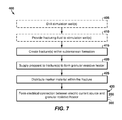
- FIG. 7 is a flowchart depicting methods according to the present disclosure of forming a subterranean structure that includes a granular resistive heater.
- FIG. 1 is a schematic cross-sectional view of illustrative, non-exclusive examples of a drilling operation 20 and/or a hydrocarbon production operation 21 that may utilize the systems and methods according to the present disclosure.
- a plurality of wellbores 30 are configured to provide mechanical, electrical, and/or fluid communication between a surface region 40 and a subterranean structure 50 , such as a granular resistive heater 52 , that is formed within a subterranean region 45 and that includes a marker material 100 .
- Wellbores 30 additionally or alternatively may be referred to as, and/or as forming a portion of, wells 30 .
- wellbores 30 may include, be utilized as, and/or be a stimulation well 32 that is configured to provide a stimulant fluid to a subterranean formation 80 and/or to subterranean structure 50 thereof, an electrode well 34 that is configured to provide an electrical connection between an electric current source and the subterranean structure, and/or a hydrocarbon well 38 that is configured to produce hydrocarbons 82 from subterranean formation 80 and/or subterranean structure 50 thereof.
- subterranean formation 80 may include any suitable oil shale, tar sands, and/or organic-rich rock formation that may contain and/or include one or more hydrocarbons 82 , such as kerogen and/or bitumen, and wellbores 30 may be utilized to stimulate the subterranean formation and/or to produce hydrocarbons 82 from the subterranean formation.
- hydrocarbons 82 such as kerogen and/or bitumen
- subterranean structure may refer to any suitable structure that is present within subterranean region 45 and which includes marker material 100 distributed therein. It is within the scope of the present disclosure that at least a portion of subterranean structure 50 may be constructed, may include material deposited from surface region 40 via a wellbore 30 , and/or may be man-made. Additionally or alternatively, it is also within the scope of the present disclosure that at least a portion of subterranean structure 50 may be naturally occurring. Whether the subterranean structure is man-made or naturally occurring, marker material 100 is not naturally occurring within the subterranean structure and/or is not naturally occurring within the subterranean structure at the concentrations that are utilized herein. Instead, the marker material is purposefully placed, directed, localized, situated, spread, dispersed, broadcast, dispensed, and/or distributed within the subterranean structure as part of, and/or in conjunction with, the systems and methods that are disclosed herein.
- a well 30 in the form of a stimulation well 32 may be utilized to provide a stimulation fluid through perforations 39 in a casing 31 thereof and into subterranean formation 80 .
- the stimulation fluid may create one or more fractures 60 within the subterranean formation. Fracture(s) 60 may form a portion of and/or define an outer boundary of subterranean structure 50 .
- a proppant material 62 such as which may be and/or include a granular resistive heating material 53 , may be provided to the fracture to maintain fracture 60 in an open configuration; and cement 64 may be utilized to hold, maintain, and/or otherwise affix at least a portion of proppant material 62 in place such that the proppant material may resist displacement from fracture 60 due to fluid flow therethrough and/or pressure differentials thereacross.
- the granular resistive heater may be in electrical communication with an electric current source, which may provide electric current to the granular resistive heater to heat subterranean formation 80 .
- Intersection 90 may additionally or alternatively be referred to herein as an intersection region and/or intersection point.
- Illustrative, non-exclusive examples of stimulation well-proximal thickness 56 include thicknesses of at least 3 mm, at least 4 mm, at least 5 mm, at least 6 mm, at least 7 mm, or at least 8 mm, as well as thicknesses of less than 12 mm, less than 11 mm, less than 10 mm, less than 9 mm, less than 8 mm, less than 7 mm, less than 6 mm, or less than 5 mm.
- Illustrative, non-exclusive examples of electrode well-proximal thickness 58 include thicknesses of at least 0.25 mm, at least 0.5 mm, at least 0.75 mm, at least 1 mm, at least 1.25 mm, at least 1.5 mm, at least 1.75 mm, at least 2 mm, at least 2.25 mm, or at least 2.5 mm, and additionally or alternatively include thicknesses of less than 5 mm, less than 4 mm, less than 3.5 mm, less than 3 mm, less than 2.75 mm, less than 2.5 mm, less than 2.25 mm, less than 2 mm, less than 1.75 mm, less than 1.5 mm, less than 1.25 mm, or less than 1 mm.
- the systems and methods disclosed herein are not limited to the above illustrative, non-exclusive examples, and it is within the scope of the present disclosure that the systems and methods may be used with regions that have thicknesses that are within and/or outside of these non-exclusive examples.
- the granular resistive heater 52 may include any suitable size and/or dimensions.
- a length (or other maximum dimension) of the granular resistive heater may be at least 50, at least 60, at least 70, at least 80, at least 90, at least 100, at least 110, at least 125, or at least 150 meters.
- a width (or other transverse dimension relative to the length) of the granular resistive heater may be at least 25, at least 30, at least 35, at least 40, at least 45, at least 50, at least 55, at least 60, or at least 70 meters.
- the granular resistive heater may additionally or alternatively be referred to as the height and width, width and height, and/or maximum and minimum transverse dimensions of the granular resistive heater.
- the granular resistive heater may include any suitable shape, an illustrative, non-exclusive example of which includes a planar, or at least substantially planar, shape.
- Illustrative, non-exclusive examples of granular resistive heaters, stimulation wells, and/or electrode wells that may be utilized with the system and methods according to the present disclosure are disclosed in U.S. Patent Application Ser. No. 61/555,940, the complete disclosure of which is hereby incorporated by reference.
- a drilling rig 22 including a drill string 24 may be utilized to create wellbore 30 using a drill bit 26 .
- Drill bit 26 may remove cuttings 102 from a terminal end 36 , which also may be referred to herein as terminal depth 36 , of wellbore 30 , and the cuttings may be conveyed through wellbore 30 to surface region 40 in a drilling fluid 101 .
- wellbore 30 may have, or include, a current terminal depth 36 at a given time during formation of the wellbore. Subsequently, and as shown in dash-dot lines in FIG. 1 , terminal depth 36 of wellbore 30 may be increased by drilling operation 20 to a future terminal depth that is greater than the current terminal depth.
- drill string 24 may include a detector 120 that is configured to detect the intersection of the wellbore with the subterranean structure.
- detector 120 may be configured to detect marker material 100 and/or to generate an intersection signal responsive to detection of the marker material.
- detector 120 may be located within surface region 40 , in communication with drilling rig 22 , and/or associated with drilling rig 22 .
- detector 120 may be configured to (1) detect the presence of marker material 100 within drilling fluid 101 and/or cuttings 102 that flow to surface region 40 from wellbore 30 and to (2) generate the intersection signal responsive thereto.
- detector 120 may be configured to detect a separation distance 122 between the detector and the marker material, between surface region 40 and the marker material, between drilling rig 22 and the marker material, and/or between drill bit 26 and the marker material.
- drilling operation 20 and/or hydrocarbon production operation 21 may include a control system 130 that is configured to control the operation of drilling rig 22 and/or drill string 24 thereof.
- control system 130 may be configured to cease drilling wellbore 30 responsive to receipt of the intersection signal.
- control system 130 may be configured to cease drilling wellbore 30 and/or to generate the intersection signal responsive to detecting that terminal depth 36 of wellbore 30 is equal to, or within a threshold distance of, separation distance 122 .
- Control system 130 may include any suitable structure that is configured to control the operation of drilling rig 22 and/or drill string 24 thereof.
- the control system may include and/or be an electronic controller, an automated controller, and/or a manually actuated controller.
- the control system may be configured to generate the intersection signal, and/or to receive the intersection signal from, detector 120 and automatically control the operation of drilling rig 22 responsive thereto.
- the control system may include an indicator that may indicate to a user that wellbore 30 has intersected subterranean structure 50 , and the user may control the operation of the drilling rig based thereon.
- Detector 120 may include any suitable structure that is configured to detect the presence of marker material 100 and/or the separation distance between the detector and the marker material.
- the detector when the detector is configured to detect marker material 100 that is proximal to and/or in contact with the detector, the detector may include a logging-while-drilling transducer 124 that is located on the drill string. It is within the scope of the present disclosure that the logging-while-drilling transducer may be located upon and/or otherwise associated with or coupled to any suitable portion of the drill string.
- the logging-while-drilling transducer may be located within a threshold distance of drill bit 26 and/or a terminal end of the drill string.
- threshold distances include threshold distances of less than 1 meter, less than 0.75 meters, less than 0.5 meters, less than 0.25 meters, or less than 0.1 meters.
- the detector may be configured to detect the presence and/or concentration of marker material 100 within cuttings 102 and/or drilling fluid 101 .
- detector 120 when detector 120 is configured to detect separation distance 122 and/or to remotely detect the marker material, the detector may include any suitable receiver that is configured to detect any suitable signal emitting or otherwise emanating or propagating from the marker material. Additionally or alternatively, detector 120 and/or control system 130 also may include any suitable transmitter that is configured to provide an excitation signal to marker material 100 , with the excitation signal causing the emission of the signal from the marker material.
- detector 120 may be configured to provide a signal electric field, a signal magnetic field, and/or signal electromagnetic radiation to the marker material over the separation distance and to receive a resultant electric field, a resultant magnetic field, and/or resultant electromagnetic radiation from the marker material over the separation distance.
- separation distances include separation distances of greater than 1 meter, greater than 5 meters, greater than 10 meters, greater than 25 meters, greater than 50 meters, greater than 100 meters, greater than 250 meters, greater than 500 meters, or greater than 1,000 meters, as well as separation distances of less than 10,000 meters, less than 7,500 meters, less than 5,000 meters, less than 2,500 meters, less than 1,000 meters, less than 750 meters, less than 500 meters, or less than 250 meters.
- Marker material may be present within the subterranean structure at any suitable concentration and/or any suitable concentration distribution.
- concentration of the marker material within the subterranean structure may be less than 5 volume %, less than 3 volume %, less than 2 volume %, less than 1 volume %, less than 0.75 volume %, less than 0.5 volume %, less than 0.25 volume %, less than 0.1 volume %, less than 0.05 volume %, less than 0.01 volume %, or less than 0.005 volume %.
- the concentration of the marker material within the subterranean structure may be greater than 0.001 volume %, greater than 0.005 volume %, greater than 0.01 volume %, greater than 0.05 volume %, greater than 0.1 volume %, greater than 0.25 volume %, or greater than 0.5 volume %.
- marker material 100 may include a plurality of discrete marker bodies that may include any suitable shape and/or distribution of shapes.
- at least a portion of the plurality of discrete marker material particles may include a spherical structure, an at least substantially spherical structure, and/or an elongate structure.
- the detector may be configured to generate the intersection signal responsive to detecting a portion of the plurality of discrete marker bodies.
- Marker material 100 may be selected based, at least in part, on a target, or desired, distribution of the plurality of discrete marker bodies within the subterranean structure, a density of a fluid that may be present within the subterranean structure, a viscosity of a fluid that may be present within the subterranean structure, and/or an average pore size within the subterranean structure.
- a shape, volume, density, and/or settling velocity of the plurality of discrete marker material particles may be selected based, at least in part, on the desired distribution.
- the plurality of discrete marker material particles may be selected such that an average characteristic dimension, such as an average diameter, equivalent diameter, and/or length, may be within a desired range of values.
- average characteristic dimensions include average characteristic dimensions that are less than 250, less than 200, less than 150, less than 125, less than 100, less than 75, less than 50, less than 25, less than 10, less than 5, less than 2, less than 1, less than 0.5, or even less than or equal to 0.1 micrometers, as well as average characteristic dimensions that are greater than 0.05, greater than 0.1, greater than 1, greater than 2, greater than 5, greater than 10, greater than 20, greater than 25, or greater than 50 micrometers.
- marker material 100 may include a first marker material and a second marker material that is different from the first marker material. It is also within the scope of the present disclosure that, as shown schematically in FIG. 2 , first marker material 104 may be distributed in a different portion, or region, of subterranean structure 50 than second marker material 106 . This may include the first marker material being distributed in a region, or ring, that surrounds the second marker material, as shown in FIG. 2 , or vice versa.
- the first marker material and the second marker material may be distributed in different regions of the subterranean structure using any suitable system and/or method.
- the first marker material may be injected into the subterranean structure prior to the second marker material.
- one or more flow characteristics of the first marker material may be selected to be different from those of the second marker material, which may cause and/or produce a segregation of the marker materials within the subterranean structure.
- the first and second marker materials may be delivered to the subterranean structure using different wells.
- detector 120 may be configured to determine one or more characteristics of the marker material that may indicate and/or identify the marker material as the first marker material and/or the second marker material. As illustrative, non-exclusive examples, the detector may be configured to detect differences in the size, shape, and/or emission from the first marker material and the second marker material.
- Marker material 100 , first marker material 104 , and/or second marker material 106 may include any suitable structure and/or material that is configured to mark, denote, and/or otherwise indicate the presence of subterranean structure 50 and/or the intersection of wellbore 30 with the subterranean structure.
- Illustrative, non-exclusive examples of marker material 100 according to the present disclosure include any suitable micromarker, radio frequency identification (RFID) device, wireless identification (WID) device, long wavelength (LW) device, active device, passive device, micromaterial, electromagnetic material, magnetic material, fluorescent material, radioactive material, and/or piezoelectric material.
- RFID radio frequency identification
- WID wireless identification
- LW long wavelength
- marker material 100 may include magnetite.
- detector 120 may include and/or be a bulk magnetic susceptibility meter that is configured to detect the magnetic susceptibility of one or more materials that may be proximal to the bulk magnetic susceptibility meter.
- a magnetic susceptibility of magnetite which is approximately 3,000,000 micro SI units, may be many orders of magnitude larger than a magnetic susceptibility of a remainder of the materials that may be present within subterranean region 45 .
- the magnetic susceptibility of magnetite may be at least 100, at least 250, at least 500, at least 750, at least 1,000, at least 5,000, at least 10,000, at least 15,000, at least 20,000, or at least 25,000 times larger than the magnetic susceptibility of the remainder of the materials that may be present within the subterranean region and/or a concentration-based average thereof.
- This large difference in magnetic susceptibility which also may be referred to herein as a magnetic susceptibility contrast, may provide for accurate detection of relatively low concentrations of magnetite by detector 120 .
- the magnetite may be present within the subterranean structure as a plurality of discrete magnetite particles, each of which may include at least one north magnetic pole and at least one south magnetic pole. It is within the scope of the present disclosure that at least a coherent fraction of the plurality of discrete magnetite particles may be aligned within the subterranean structure with their north poles pointing within a threshold coherence angle of the same direction.
- the threshold coherence angle may include an angle of less than 30 degrees, less than 25 degrees, less than 20 degrees, less than 15 degrees, less than 10 degrees, less than 5 degrees, less than 3 degrees, or less than 1 degree.
- the coherent fraction may include at least 25%, at least 40%, at least 50%, at least 60%, at least 70%, at least 75%, at least 80%, or at least 90% of the plurality of discrete magnetite particles.
- At least a single domain fraction of the plurality of discrete magnetite particles may include only one magnetic domain.
- Illustrative, non-exclusive examples of the single domain fraction according to the present disclosure include single domain fractions of at least 25%, at least 30%, at least 40%, at least 50%, at least 60%, at least 70%, at least 75%, at least 80%, at least 90%, at least 95%, or at least 99% of the plurality of discrete magnetite particles.
- At least a multi-domain fraction of the plurality of discrete magnetite particles may include a plurality of magnetic domains.
- Illustrative, non-exclusive examples of the multi-domain fraction of the plurality of discrete magnetite particles include multi-domain fractions of less than 90%, less than 80%, less than 75%, less than 70%, less than 60%, less than 50%, less than 40%, less than 30%, less than 25%, less than 20%, less than 10%, or less than 5% of the plurality of discrete magnetite particles.
- the marker material includes the multi-domain fraction of the plurality of discrete magnetite particles
- it is within the scope of the plurality of magnetic domains within each of the multi-domain magnetic particles may be aligned with one another to within a threshold alignment angle.
- threshold alignment angles include threshold alignment angles of less than 30 degrees, less than 25 degrees, less than 20 degrees, less than 15 degrees, less than 10 degrees, less than 5 degrees, less than 3 degrees, or less than 1 degree.
- the plurality of magnetic domains may be aligned using any suitable system and/or method.
- the plurality of magnetic domains may be aligned by heating the plurality of discrete magnetite particles, applying a magnetic field to the plurality of discrete magnetite particles to at least substantially align the plurality of magnetic domains, and cooling the plurality of discrete magnetite particles to maintain the plurality of magnetic domains in the at least substantially aligned configuration.
- wellbore 30 may be utilized as an electrode well 34 to provide an electric current through an electrical conduit 35 to granular resistive heater 52 .
- electrode well 34 may include and/or contain a supplemental material 54 .
- the electrode well may include a particulate conductor 55 that is configured to provide an electrical connection between electrical conduit 35 and granular resistive heater 52 and/or to more evenly distribute the electric current that flows through the electrical conductor into the granular resistive heater.
- supplemental material 54 may be desirable to provide for accurate supply of supplemental material 54 to a portion of wellbore 30 that includes subterranean structure 50 .
- this may include supplying supplemental material 54 to the portion of the wellbore that includes granular resistive heater 52 . This may be accomplished through accurate control of terminal depth 36 of wellbore 30 and/or accurate detection of intersection point 90 .
- thickness 58 of the granular resistive heater in a region that is proximal to the electrode well may be only on the order of a few millimeters. Thus, it may be difficult to accurately detect intersection point 90 without the use of the systems and methods that are disclosed herein.
- the granular resistive heater may be too thin to effectively heat subterranean formation 80 and/or the portion of the granular resistive heater that is proximal to the electrode well may be too thin to adequately conduct the electric current to a remainder of the granular resistive heater.
- a new electrode well may be drilled to replace and/or supplement the current electrode well. This new electrode well may be drilled at a location that is closer to stimulation well 32 in an effort to intersect granular resistive heater 52 at a thicker location.
- thickness 58 is greater than a target, or threshold, thickness, it may be desirable to drill a new electrode well at a location that is farther from stimulation well 32 in an effort to increase the overall size and effectiveness of the granular resistive heater.
- FIG. 2 is a schematic top view of illustrative, non-exclusive examples of subterranean structure 50 that may be intersected by a plurality of wellbores 30 according to the present disclosure.
- FIG. 2 illustrates that, as discussed in more detail herein, a stimulation well 32 may be present within a central region, or zone, of subterranean structure 50 , and may be utilized to create a fracture 60 .
- Fracture 60 may contain proppant 62 , in the form of and/or including granular resistive heating material 53 , which may form granular resistive heater 52 .
- Subterranean structure 50 also may include marker material 100 that may be utilized to detect the intersection point between electrode wells 34 and the subterranean structure.
- marker material 100 may include a first marker material 104 and a second marker material 106 that may be distributed in different zones, or regions, of the subterranean structure.
- a plurality of electrode wells 34 may provide electric current to and/or remove electric current from granular resistive heater 52
- supplemental material 54 may be proximal to and/or surround electrode wells 34 to provide for uniform supply of the electric current to the granular resistive heater.
- any wellbore 30 including stimulation well(s) 32 and/or electrode well(s) 34 also may be, include, and/or be utilized as hydrocarbon wells 38 , which also may be referred to herein as production wells 38 .
- FIG. 3 is a schematic cross-sectional view of illustrative, non-exclusive examples of an electrical connection 37 between a subterranean structure 50 that includes a granular resistive heater 52 and an electrical conduit 35 .
- granular resistive heater 52 may include a granular resistive heating material 53 , which also may function and/or be referred to as a proppant 62 , and a marker material 100 in the form of a plurality of discrete marker bodies.
- the granular resistive heating material may include any suitable size and/or characteristic dimension.
- an average characteristic dimension of the granular resistive heating material may be at least 50, at least 75, at least 80, at least 90, at least 100, at least 110, at least 120, or at least 125 micrometers. Additionally or alternatively, the average characteristic dimension may less than 200, less than 175, less than 150, less than 125, or less than 100 micrometers.
- marker material 100 is shown schematically as being present within interstitial spaces between individual granular resistive heating material 53 and/or proppant 62 particles. As discussed in more detail herein, such a configuration may exist when marker material 100 is separate from proppant 62 and provided to the subterranean structure concurrently with and/or subsequent to proppant 62 . Additionally or alternatively, and as indicated in FIG. 3 at 103 , it is also within the scope of the present disclosure that the marker material may form a portion of, be incorporated into, and/or be proppant 62 .
- the average characteristic dimension of the plurality of discrete marker material particles may be less than an average pore size of the interstitial spaces that are present within the granular resistive heater.
- supplemental material 54 may be provided to a region of the wellbore that is in fluid communication with granular resistive heater 52 .
- the supplemental material may form an electrical connection between electrical conduit 35 and granular resistive heating material 53 of the granular resistive heater, thereby decreasing a resistance to electric current flow and/or increasing a uniformity of electric current flow therebetween.
- FIG. 4 is a schematic cross-sectional view of illustrative, non-exclusive examples of wellbores 30 that include one or more packers 28 to focus, or target, delivery of supplemental material 54 to subterranean structure 50 that may be present within subsurface region 45 and/or subterranean formation 80 .
- a packer 172 may be placed within the wellbore and below the subterranean structure to limit a flow of supplemental material 54 therepast.
- a second packer 174 may be placed within the wellbore and above the subterranean structure and a fluid conduit 29 may be utilized to provide the supplemental material directly, or at least substantially directly, to the subterranean structure.
- packers 172 and 174 may facilitate accurate delivery of the supplemental material to the subterranean structure, it may be time-consuming and/or comparatively expensive to locate the packers within wellbore 30 . In addition, it may be difficult to determine a desired location for the packers, since a distance between terminal depth 36 and subterranean structure 50 may be unknown and/or difficult to determine.
- the systems and methods disclosed herein may provide for accurate determination of intersection point 90 between wellbore 30 and subterranean structure 50 .
- supplemental material 54 may be provided to the subterranean structure without the need for packer 172 .
- a location for packer 174 may be accurately determined since a distance between terminal depth 36 and subterranean structure 50 is known.
- supplemental material 54 may be provided to subterranean structure 50 without the use of packer 174 and/or fluid conduit 29 .
- FIG. 5 is a flowchart depicting methods 200 according to the present disclosure of detecting an intersection of a wellbore with a subterranean structure.
- the methods may include selecting a marker material at 205 , distributing the marker material within the subterranean structure at 210 , distributing a second marker material within the subterranean structure at 215 and/or aligning the marker material within the subterranean structure at 220 .
- the methods further may include drilling the wellbore at 225 and detecting an intersection, or intersection point, of the wellbore with the subterranean structure at 230 .
- the methods further may include determining a character of the marker material that is present at the intersection point at 235 , ceasing drilling the wellbore at 240 , repeating the method at 245 , and/or producing a hydrocarbon from the subterranean structure at 250 .
- Selecting the marker material at 205 may include the use of any suitable system, method, and/or criteria to select the marker material that may be distributed within the subterranean structure.
- Illustrative, non-exclusive examples of marker materials according to the present disclosure are discussed in more detail herein.
- the selecting may include selecting the type, configuration, and/or materials of construction of the marker material.
- the selecting may include selecting a shape, volume, density, and/or settling velocity of the plurality of discrete marker material particles that are included in the marker material based, at least in part, on a desired distribution of the discrete marker material particles within the subterranean structure, a density of a fluid that is present within the subterranean structure, a viscosity of the fluid that is present within the subterranean structure, and/or an average pore size within the subterranean structure.
- Distributing the marker material within the subterranean structure at 210 may include the use of any suitable system and/or method to disperse, spread, and/or distribute the marker material within the subterranean structure.
- the distributing may include injecting the marker material into the subterranean structure, such as through any suitable fluid conduit and/or casing.
- the distributing may include injecting a slurry that includes the marker material and/or water into the subterranean structure.
- the distributing may include injecting the marker material into the subterranean structure from a stimulation well that may be utilized to form at least a portion of the subterranean structure. It is within the scope of the present disclosure that the distributing may include producing or otherwise providing any suitable concentration of the marker material within the subterranean structure, including the illustrative, non-exclusive examples of which that are discussed in more detail herein.
- the marker material may be incorporated into and/or form a portion of a proppant that is present within the subterranean structure.
- the distributing may include distributing the marker material with the proppant. Additionally or alternatively, and as also discussed in more detail herein, the marker material may be separate from the proppant. When the marker material is separate from the proppant, the distributing may include distributing the marker material subsequent to supplying the proppant to the subterranean structure.
- the marker material may include only a single type of marker material
- the marker material also may include a first marker material and a second marker material.
- the methods further may include distributing the second marker material at 215 .
- the distributing may include distributing the first marker material into a different portion of the subterranean structure than the second marker material and/or distributing the first marker material in a ring around the second marker material.
- this may include injecting the first marker material and the second marker material into the subterranean structure at different locations, injecting the first marker material into the subterranean structure at a different time than the second marker material, and/or selecting one or more flow properties of the first marker material to be different from one or more flow properties of the second marker material such that the marker materials naturally concentrate within different portions of the subterranean structure.
- one or more properties of the first marker material may differ from a corresponding property of the second marker material.
- a shape, volume, density, settling velocity, size, material of construction, excitation mode, and/or emission of the first marker material may be selected to be different from a corresponding property of the second marker material.
- Aligning the marker material at 220 may include the use of any suitable system and/or method to align at least a portion of the plurality of discrete marker material particles that may be present within the subterranean structure.
- a portion of the plurality of discrete marker material particles may include and/or be an elongate structure that includes a longitudinal axis, and the aligning may include aligning the longitudinal axis of the portion of the plurality of discrete marker material particles.
- the aligning may include aligning the longitudinal axis of the portion of the plurality of discrete marker material particles along a common axis and/or aligning the longitudinal axis of the portion of the plurality of discrete marker material particles within and/or parallel to a common plane.
- the aligning may include flowing the marker material through the subterranean structure, flowing a fluid past the marker material after the marker material is present within the subterranean structure, applying an electric field to the marker material within the subterranean structure, applying a magnetic field to the marker material within the subterranean structure, and/or self-alignment of the marker material within the subterranean structure.
- a coherent fraction of the plurality of discrete marker material particles may be aligned to within a threshold coherence angle of the same direction. Illustrative, non-exclusive examples of the coherent fraction and/or the threshold coherence angle are discussed in more detail herein.
- the aligning may improve and/or increase a sensitivity of the detecting at 230 .
- the aligning may improve and/or increase a coherence of one or more electric, magnetic, and/or electromagnetic fields that may be associated with the marker material and/or utilized by the detector during the detecting.
- the aligning may include aligning the magnetite into a coherent, or at least substantially coherent layer within the subterranean structure.
- a magnetic field strength of the coherent layer of magnetite may be much larger than a magnetic field strength of the discrete, or individual, magnetite particles that are present within the magnetite when they are not aligned.
- a detector that is configured to detect magnetic field strength and/or magnetic susceptibility may detect the subterranean structure with higher accuracy and/or greater resolution when the magnetite forms a coherent layer due to the increased magnetic field strength.
- Drilling the wellbore at 225 may include the use of any suitable system and/or method to drill the wellbore.
- the drilling may include the use of a drilling rig, a drill string, and/or a drill bit to drill the wellbore. Any suitable control system and/or control strategy may be utilized to control the drilling.
- Detecting the intersection of the wellbore with the subterranean structure at 230 may include the use of any suitable system and/or method to detect the intersection point between the wellbore and the subterranean structure.
- the detecting may include detecting the marker material with a detector that is attached to and/or forms a portion of the drill string, an illustrative, non-exclusive example of which includes a logging-while-drilling transducer.
- the logging-while-drilling transducer may be located near the drill bit that is associated with the drill string and/or near a terminal end of the drill string.
- the logging-while-drilling transducer may be less than 1 meter, less than 0.75 meters, less than 0.5 meters, less than 0.25 meters, or less than 0.1 meters from the drill bit and/or the terminal end of the drill string.
- the logging-while-drilling transducer may include a bulk susceptibility meter that is configured to detect a bulk magnetic susceptibility of cuttings that are produced during the drilling.
- the detecting may include remotely detecting the marker material.
- the remotely detecting may include supplying a signal electric field, a signal magnetic field, and/or signal electromagnetic radiation to the marker material and/or receiving a resultant electric field, a resultant magnetic field, and/or resultant electromagnetic radiation from the marker material over a separation distance between the marker material and the detector.
- separation distances are discussed in more detail herein.
- Determining the character of the marker material at 235 may include the use of any suitable system and/or method to determine any suitable property of the marker material.
- the determining may include detecting a concentration of the marker material.
- the determining may include detecting an identity of the marker material and/or detecting a ratio of a concentration of the first marker material to a concentration of the second marker material.
- Ceasing drilling the wellbore at 240 may include ceasing the drilling responsive, at least in part, to detecting the intersection at 230 and/or detecting the marker material. It is within the scope of the present disclosure that, as discussed in more detail herein, the ceasing may include ceasing such that a terminal depth of the wellbore is within a threshold distance of a target portion of the subterranean structure.
- threshold distances include threshold distances of less than 1,000 millimeters (mm), less than 500 mm, less than 250 mm, less than 100 mm, less than 50 mm, less than 25 mm, less than 10 mm, less than 5 mm, less than 4 mm, less than 3 mm, less than 2 mm, less than 1 mm, less than 0.5 mm, or less than 0.1 mm.
- target portions of the subterranean structure include a top surface, a bottom surface, a midline, and/or a central region of the subterranean structure.
- Repeating the method at 245 may include repeating at least drilling the wellbore at 225 and detecting the intersection at 230 based on any suitable criteria.
- the repeating may include drilling a second wellbore responsive, at least in part, to the detecting at 230 and/or the determining at 235 .
- Producing hydrocarbons from the subterranean structure at 250 may include the use of any suitable system and/or method to pump and/or otherwise convey one or more hydrocarbons from the subterranean structure.
- the producing may include generating a liquid and/or gaseous hydrocarbon within the subterranean formation and/or the subterranean structure and/or pumping the one or more hydrocarbons from the subterranean formation and/or the subterranean structure to surface region 40 .
- FIG. 6 is a flowchart depicting methods 300 according to the present disclosure of forming an electrical connection between a granular resistive heater that is present within a subterranean structure and an electric current source.
- the methods include detecting an intersection of a wellbore with the subterranean structure at 305 and may include placing one or more packers within the wellbore at 310 .
- the methods further include providing a particulate conductor through the wellbore and to a portion of the granular resistive heater at 315 , forming an electrical connection between the particulate conductor and the granular resistive heater at 320 , and forming an electrical connection between the particulate conductor and the electric current source at 325 .
- the methods further many include repeating the method at 330 and/or heating the subterranean formation with the granular resistive heater at 335 .
- Detecting the intersection of the wellbore with the subterranean structure at 305 may include the use of any suitable system and/or method to determine that the wellbore has intersected, contacted, and/or is in fluid communication with the subterranean structure.
- the detecting may include performing methods 200 to detect the intersection of the wellbore with the subterranean structure.
- Placing one or more packers within the wellbore at 310 may include the use of any suitable packer to occlude flow of fluid into one or more portions of the wellbore and/or to maintain a fluid that is provided to the wellbore within a target, or desired, portion of the wellbore.
- the placing may include placing the one or more packers within the wellbore and adjacent to the subterranean structure.
- the placing may include placing a packer uphole from the subterranean structure and/or placing a packer downhole from the subterranean structure.
- Providing the supplemental material to the granular resistive heater at 315 may include providing any suitable supplemental material to any suitable portion of the granular resistive heater.
- the providing may include providing the supplemental material to a portion of the granular resistive heater that is proximal to the wellbore.
- the providing may include flowing the particulate conductor into the portion of the granular resistive heater that is proximal to the wellbore.
- the providing may include pumping a slurry that includes the supplemental material into the wellbore.
- the providing may include providing the supplemental material to a portion of the wellbore that is bounded by at least one of the one or more packers and which includes the subterranean structure.
- the supplemental material may include any suitable material that is configured to provide an electrical connection between the granular resistive heater and the electric current source, illustrative, non-exclusive examples of which include a particulate conductor, carbon, graphite, a metallic material, a metal particulate, and/or metal hairs/strands.
- the supplemental material may include any suitable size, average size, and/or size distribution.
- the granular resistive heater may include a porous structure that includes an average pore size and an average characteristic dimension of the supplemental material may be less than the average pore size.
- Forming electrical connections at 320 and 325 may include the use of any suitable structure to form an electrical connection between the granular resistive heater and the electric current source.
- the forming may include flowing the supplemental material into a portion of the granular resistive heater such that a portion of the supplemental material is in electrical communication with the portion of the granular resistive heater, filling a portion of the wellbore with the supplemental material, and/or placing an electrical conduit in electrical communication with both the supplemental material and the electric current source.
- Repeating the method at 330 may include repeating the method to form a second (and/or subsequent) well and/or wellbore that may be utilized to form a second electrical connection between the electric current source and the granular resistive heater.
- the two (or more) wellbores may be spaced apart from each another.
- a stimulation well may be at least substantially between the two or more wellbores.
- the wellbores may be located on at least substantially opposite sides of the granular resistive heater or otherwise distributed in a spaced relation therein.
- Heating the subterranean formation at 335 may include providing an electric current to the granular resistive heater from the electric current source, generating heat with the granular resistive heater due to the flow of electric current therethrough, and/or conducting the heat that is generated by the granular resistive heater into the subterranean formation. It is within the scope of the present disclosure that the heating may include performing a shale oil retort process, a shale oil heat treating process, a hydrogenation process, a thermal dissolution process, and/or an in situ shale oil conversion process within the subterranean formation.
- the heating may include converting a hydrocarbon, such as kerogen and/or bitumen, that is present within the subterranean formation into a liquid hydrocarbon, a gaseous hydrocarbon, and/or shale oil that may be produced from the subterranean formation by one or more production wells.
- a hydrocarbon such as kerogen and/or bitumen
- FIG. 7 is a flowchart depicting methods 400 according to the present disclosure of forming a subterranean structure that includes a granular resistive heater.
- the methods may include drilling one or more stimulation wells at 405 and providing a fracturing fluid to the one or more stimulation wells at 410 .
- the methods further include creating one or more fractures within the subterranean formation 415 , supplying a proppant to the one or more fractures to form the granular resistive heater 420 , distributing a marker material within the fracture and/or the granular resistive heater at 425 , and/or forming an electrical connection between an electric current source and the granular resistive heater at 430 .
- Drilling one or more stimulation wells at 405 may include the use of any suitable system and/or method to drill a stimulation well into the subterranean formation.
- the one or more stimulation wells may be configured to provide a stimulant fluid to the subterranean formation to stimulate production from the subterranean formation.
- Providing the fracturing fluid to the one or more stimulation wells at 410 may include providing any suitable fluid that is configured to stimulate the subterranean formation.
- the providing may include increasing a hydraulic pressure within a portion of the subterranean formation and/or creating the one or more fractures within the subterranean formation at 415 .
- each of the one or more fractures may include any suitable orientation and/or be of any suitable size.
- the one or more fractures may include at least substantially vertical and/or at least substantially horizontal fractures.
- the one or more fractures may include at least substantially planar fractures.
- Supplying the proppant to the one or more fractures at 420 may include supplying any suitable proppant that is configured to maintain the one or more fractures in an open configuration.
- the proppant may include a porous structure that is configured to provide for fluid flow therethrough.
- the proppant may include a granular resistive heating material that forms a portion of the granular resistive heater.
- the granular resistive heating material may include a resistive material that is configured to generate heat when an electric current is passed therethrough, an illustrative, non-exclusive example of which includes calcined petroleum coke.
- Distributing the marker material within the fracture at 425 may include the use of any suitable system and/or method to distribute the marker material.
- the distributing may include distributing a first marker material and a second marker material into the fracture.
- the distributing may include distributing the first marker material into a different portion of the fracture than the second marker material.
- the distributing may include distributing the first marker material into a first fracture of the plurality of fractures and distributing the second marker material into a second fracture of the plurality of fractures.
- the marker material may be separate from the proppant.
- the marker material may be configured, designed, and/or selected to have a settling velocity that is within a threshold difference of a settling velocity of the proppant.
- threshold differences include threshold differences of less than 50%, less than 40%, less than 30%, less than 25%, less than 20%, less than 15%, less than 10%, less than 5%, or less than 1%.
- the marker material may be incorporated into a matrix material to form a composite marker material that includes a density that provides the desired settling velocity.
- the marker material may form a portion of the proppant.
- the supplying at 420 also may include and/or may be performed concurrently with the distributing at 425 .
- Forming the electrical connection between the electric current source and the granular resistive heater at 430 may include the formation of any suitable electrode well that may be configured to provide the electrical connection.
- the forming may include detecting an intersection of a wellbore that is associated with the electrode well and the granular resistive heater using methods 200 and/or forming the electrical connection between the granular resistive heater and the electric current source using methods 300 .
- the term “and/or” placed between a first entity and a second entity means one of (1) the first entity, (2) the second entity, and (3) the first entity and the second entity.
- Multiple entities listed with “and/or” should be construed in the same manner, i.e., “one or more” of the entities so conjoined.
- Other entities may optionally be present other than the entities specifically identified by the “and/or” clause, whether related or unrelated to those entities specifically identified.
- a reference to “A and/or B,” when used in conjunction with open-ended language such as “comprising” may refer, in one embodiment, to A only (optionally including entities other than B); in another embodiment, to B only (optionally including entities other than A); in yet another embodiment, to both A and B (optionally including other entities).
- These entities may refer to elements, actions, structures, steps, operations, values, and the like.
- the phrase “at least one,” in reference to a list of one or more entities should be understood to mean at least one entity selected from any one or more of the entity in the list of entities, but not necessarily including at least one of each and every entity specifically listed within the list of entities and not excluding any combinations of entities in the list of entities.
- This definition also allows that entities may optionally be present other than the entities specifically identified within the list of entities to which the phrase “at least one” refers, whether related or unrelated to those entities specifically identified.
- “at least one of A and B” may refer, in one embodiment, to at least one, optionally including more than one, A, with no B present (and optionally including entities other than B); in another embodiment, to at least one, optionally including more than one, B, with no A present (and optionally including entities other than A); in yet another embodiment, to at least one, optionally including more than one, A, and at least one, optionally including more than one, B (and optionally including other entities).
- each of the expressions “at least one of A, B and C,” “at least one of A, B, or C,” “one or more of A, B, and C,” “one or more of A, B, or C” and “A, B, and/or C” may mean A alone, B alone, C alone, A and B together, A and C together, B and C together, A, B and C together, and optionally any of the above in combination with at least one other entity.
- adapted and “configured” mean that the element, component, or other subject matter is designed and/or intended to perform a given function.
- the use of the terms “adapted” and “configured” should not be construed to mean that a given element, component, or other subject matter is simply “capable of” performing a given function but that the element, component, and/or other subject matter is specifically selected, created, implemented, utilized, programmed, and/or designed for the purpose of performing the function.
- elements, components, and/or other recited subject matter that is recited as being adapted to perform a particular function may additionally or alternatively be described as being configured to perform that function, and vice versa.
- the determining includes detecting the marker material.
- the method further includes ceasing the drilling the wellbore, wherein the ceasing is responsive, at least in part, to the detecting.
- the wellbore includes a terminal depth
- the ceasing includes ceasing the drilling such that the terminal depth of the wellbore is within 1,000 millimeters (mm), within 500 mm, within 250 mm, within 100 mm, within 50 mm, within 25 mm, within 10 mm, within 5 mm, within 4 mm, within 3 mm, within 2 mm, within 1 mm, within 0.5 mm, or within 0.1 mm of a target portion of the subterranean structure, optionally wherein the target portion includes a top surface, a bottom surface, or a central region of the subterranean structure.
- the distributing includes injecting the marker material into the subterranean structure, optionally wherein the injecting includes injecting a slurry including the marker material and a liquid into the subterranean structure, and further optionally wherein the liquid includes water.
- A7 The method of any of paragraphs A4-A6, wherein the distributing includes distributing the marker material into the subterranean structure such that a concentration of the marker material within the subterranean structure is less than 5 volume %, less than 3 volume %, less than 2 volume %, less than 1 volume %, less than 0.75 volume %, less than 0.5 volume %, less than 0.25 volume %, less than 0.1 volume %, less than 0.05 volume %, less than 0.01 volume %, or less than 0.005 volume %, and optionally greater than 0.001 volume %, greater than 0.005 volume %, greater than 0.01 volume %, greater than 0.05 volume %, greater than 0.1 volume %, greater than 0.25 volume %, or greater than 0.5 volume %.
- A8 The method of any of paragraphs A4-A7, wherein the distributing includes at least one of distributing the marker material within a proppant that forms a portion of the subterranean structure and distributing the marker material with the proppant to form a portion of the subterranean structure.
- the marker material includes a plurality of discrete marker material particles, wherein at least a portion of the plurality of discrete marker material particles includes an elongate structure with a longitudinal axis, and further wherein the distributing includes aligning the longitudinal axis of the portion of the plurality of discrete marker material particles, wherein the aligning includes at least one of aligning the longitudinal axis of the portion of discrete marker material particles along a common axis and aligning the longitudinal axis of the portion of discrete marker material particles parallel to a common plane.
- the aligning includes at least one of flowing the marker material through the subterranean structure, flowing a fluid past the marker material after the marker material is present within the subterranean structure, applying an electric field to the marker material within the subterranean structure, applying a magnetic field to the marker material within the subterranean structure, and self-alignment of the marker material within the subterranean structure.
- the marker material includes magnetite
- the detecting includes detecting the magnetite
- detecting the magnetite includes detecting a bulk magnetic susceptibility of cuttings that are produced while drilling the wellbore, and further optionally wherein the cuttings are produced at a terminal end of the wellbore.
- magnetite includes a plurality of discrete magnetite particles, wherein each of the plurality of discrete magnetite particles includes a plurality of magnetic poles including at least a north magnetic pole and a south magnetic pole.
- the method includes aligning the plurality of discrete magnetite particles within the subterranean structure such that a coherent fraction of the plurality of discrete magnetite particles is aligned with their north poles pointing within a threshold coherence angle of the same direction, optionally wherein the coherent fraction includes at least 25%, at least 40%, at least 50%, at least 60%, at least 70%, at least 75%, at least 80%, or at least 90% of the plurality of discrete magnetite particles, and further optionally wherein the threshold coherence angle includes an angle of less than 30 degrees, less than 25 degrees, less than 20 degrees, less than 15 degrees, less than 10 degrees, less than 5 degrees, less than 3 degrees, or less than 1 degree.
- each of the plurality of discrete magnetite particles in a single domain fraction of the plurality of discrete magnetite particles includes only one magnetic domain, and optionally wherein the single domain fraction includes at least 25%, at least 30%, at least 40%, at least 50%, at least 60%, at least 70%, at least 75%, at least 80%, at least 90%, at least 95%, or at least 99% of the plurality of discrete magnetite particles.
- each of the plurality of discrete magnetite particles in a multi-domain fraction of the plurality of discrete magnetite particles includes a plurality of magnetic domains, and optionally wherein the multi-domain fraction includes less than 90%, less than 80%, less than 75%, less than 70%, less than 60%, less than 50%, less than 40%, less than 30%, less than 25%, less than 20%, less than 10%, or less than 5% of the plurality of discrete magnetite particles.
- A17 The method of paragraph A16, wherein the plurality of magnetic domains are aligned with one another to within a threshold alignment angle, optionally wherein the threshold alignment angle is less than 30 degrees, less than 25 degrees, less than 20 degrees, less than 15 degrees, less than 10 degrees, less than 5 degrees, less than 3 degrees, or less than 1 degree.
- the method further includes aligning the plurality of magnetic domains to within the threshold alignment angle, optionally wherein the aligning includes heating the plurality of discrete magnetite particles, applying a magnetic field to the plurality of discrete magnetite particles, and cooling the plurality of discrete magnetite particles, and further optionally wherein the cooling includes cooling at least substantially concurrently with applying the magnetic field.
- A20 The method of paragraph A19, wherein the logging-while-drilling transducer is located on a drill string utilized for drilling the wellbore, optionally wherein the logging-while-drilling transducer is within a threshold distance of at least one of a drill bit that is associated with the drill string and a terminal end of the drill string, and further optionally wherein the threshold distance is less than 1 meter, less than 0.75 meters, less than 0.5 meters, less than 0.25 meters, or less than 0.1 meters.
- A23 The method of any of paragraphs A1-A22, wherein the marker material includes a plurality of discrete marker bodies, and further wherein the detecting includes detecting at least a portion of the plurality of discrete marker bodies.
- the method includes selecting at least one of a shape, a volume, a density, and a settling velocity of the plurality of discrete marker bodies based, at least in part, upon a desired distribution of the plurality of discrete marker bodies within the subterranean structure, and optionally wherein the selecting is based, at least in part, on a density of a fluid present within the subterranean structure, a viscosity of the fluid present within the subterranean structure, and an average pore size within the subterranean structure.
- A25 The method of any of paragraphs A23-A24, wherein an average characteristic dimension of the plurality of discrete marker bodies is less than 250, less than 200, less than 150, less than 125, less than 100, less than 75, less than 50, less than 25, less than 10, less than 5, less than 2, less than 1, less than 0.5, or less than or equal to 0.1 micrometers, and optionally wherein an average characteristic dimension of the plurality of discrete marker bodies is greater than 0.05, greater than 0.1, greater than 1, greater than 2, greater than 5, greater than 10, greater than 20, greater than 25, or greater than 50 micrometers.
- the distributing includes distributing the first marker material in a different portion of the subterranean structure than the second marker material, optionally by at least one of injecting the first marker material and the second marker material into the subterranean structure at different locations, injecting the first marker material at a different time than the second marker material, and selecting a flow property of the first marker material within the subterranean structure to be different form a flow property of the second marker material within the subterranean structure.
- the detecting includes determining a characteristic of the marker material that is present at an intersection point between the wellbore and the subterranean structure, and optionally wherein the characteristic of the marker material includes at least one of an identity of the marker material, a concentration of the marker material, and a ratio of a concentration of the first marker material to a concentration of the second marker material.
- A30 The method of paragraph A29, wherein the method further includes drilling a second wellbore at a second location, wherein the second location is selected based, at least in part, on the determining.
- the distributing includes selecting a property of the first marker material to be different from a property of the second marker material, and optionally wherein the property includes at least one of a shape, a volume, a density, a settling velocity, a size, a material of construction, an excitation mode, and an emission.
- the marker material includes at least one of a micromarker, an RFID device, a WID device, an LW device, an active device, a passive device, a micromaterial, an electromagnetic material, a fluorescent material, a radioactive material, and a piezoelectric material.
- remotely detecting the marker material includes providing at least one of a signal electric field, a signal magnetic field, and signal electromagnetic radiation to the marker material over a separation distance and receiving at least one of a resultant electric field, a resultant magnetic field, and resultant electromagnetic radiation from the marker material over the separation distance, optionally wherein the separation distance is greater than 1 meter, greater than 5 meters, greater than 10 meters, greater than 25 meters, greater than 50 meters, greater than 100 meters, greater than 250 meters, greater than 500 meters, or greater than 1,000 meters, and further optionally wherein the separation distance is less than 10,000 meters, less than 7,500 meters, less than 5,000 meters, less than 2,500 meters, less than 1,000 meters, less than 750 meters, less than 500 meters, or less than 250 meters.
- A37 The method of any of paragraphs A1-A36, wherein the detecting includes detecting the marker material by examining cuttings that are produced during the drilling.
- a method of forming an electrical connection between an electric current source and a granular resistive heater that forms a portion of a subterranean structure comprising:
- the supplemental material includes at least one of a particulate conductor, carbon, graphite, a metallic material, a metal particulate, and metal hairs, and optionally wherein providing the supplemental material includes pumping a slurry that includes the supplemental material into the wellbore.
- providing the supplemental material includes providing the supplemental material to a portion of the wellbore that is bounded by at least one of the one or more packers and includes the subterranean structure.
- a method of forming a granular resistive heater, wherein the granular resistive heater forms a portion of a subterranean structure that is present within a subterranean formation comprising:
- the proppant includes a porous structure that is configured to provide for fluid flow through the fracture, and further wherein the proppant includes a granular resistive heating material that forms the granular resistive heater;
- creating the fracture includes creating at least one of a vertical fracture and a horizontal fracture.
- the marker material is configured to have a settling velocity that is within a threshold difference of a settling velocity of the proppant, optionally wherein the threshold difference is less than 50%, less than 40%, less than 30%, less than 25%, less than 20%, less than 15%, less than 10%, less than 5%, or less than 1%.
- a portion of the granular resistive heater that is proximal to a/the stimulation well that is utilized to create the fracture includes an average stimulation well-proximal thickness, optionally wherein the average stimulation well-proximal thickness is at least 3 mm, at least 4 mm, at least 5 mm, at least 6 mm, at least 7 mm, or at least 8 mm and further optionally wherein the average stimulation well-proximal thickness is less than 12 mm, less than 11 mm, less than 10 mm, less than 9 mm, less than 8 mm, less than 7 mm, less than 6 mm, or less than 5 mm.
- a portion of the granular resistive heater that is proximal to the wellbore includes an average wellbore-proximal thickness, optionally wherein the average wellbore-proximal thickness is at least 0.25 mm, at least 0.5 mm, at least 0.75 mm, at least 1 mm, at least 1.25 mm, at least 1.5 mm, at least 1.75 mm, at least 2 mm, at least 2.25 mm, or at least 2.5 mm and further optionally wherein the average wellbore-proximal thickness is less than 5 mm, less than 4 mm, less than 3.5 mm, less than 3 mm, less than 2.75 mm, less than 2.5 mm, less than 2.25 mm, less than 2 mm, less than 1.75 mm, less than 1.5 mm, less than 1.25 mm, or less than 1 mm.
- the granular resistive heating material includes a resistive material that is configured to generate heat when an electric current is conducted therethrough, and optionally wherein the granular resistive heating material includes calcined petroleum coke.
- the granular resistive heating material includes a plurality of discrete heating material bodies, optionally wherein an average characteristic dimension of the plurality of discrete heating material bodies is at least 50, at least 75, at least 80, at least 90, at least 100, at least 110, at least 120, or at least 125 micrometers, and further optionally wherein the average characteristic dimension of the plurality of discrete heating material bodies is less than 200, less than 175, less than 150, less than 125, or less than 100 micrometers.
- a length of the granular resistive heater is at least 50, at least 60, at least 70, at least 80, at least 90, at least 100, at least 110, at least 125, or at least 150 meters.
- a width of the granular resistive heater is at least 25, at least 30, at least 35, at least 40, at least 45, at least 50, at least 55, at least 60, or at least 70 meters.
- heating includes performing at least one of a shale oil retort process, a shale oil heat treating process, a hydrogenation reaction, a thermal dissolution process, and an in situ shale oil conversion process within the subterranean formation.
- a system configured to detect an intersection of a wellbore with a subterranean structure, the system comprising:
- a marker material distributed within the subterranean structure; a drill string configured to drill the wellbore;
- a detector configured to generate an intersection signal responsive to detecting the marker material
- control system configured to control the operation of the drill string responsive, at least in part, to the intersection signal.
- control system includes at least one of a manually actuated control system, an automated control system, and a controller configured to perform the method of any of paragraphs A1-C18.
- the detector includes a logging-while-drilling transducer that is located on the drill string, optionally wherein the logging-while-drilling transducer is within a threshold distance of at least one of a drill bit that is associated with the drill string and a terminal end of the drill string, and further optionally wherein the threshold distance is less than 1 meter, less than 0.75 meters, less than 0.5 meters, less than 0.25 meters, or less than 0.1 meters.
- the remote detector is configured to provide at least one of a signal electric field, a signal magnetic field, and signal electromagnetic radiation to the marker material over a separation distance and receive at least one of a resultant electric field, a resultant magnetic field, and resultant electromagnetic radiation from the marker material over the separation distance, optionally wherein the separation distance is greater than 1 meter, greater than 5 meters, greater than 10 meters, greater than 25 meters, greater than 50 meters, greater than 100 meters, greater than 250 meters, greater than 500 meters, or greater than 1,000 meters, and further optionally wherein the separation distance is less than 10,000 meters, less than 7,500 meters, less than 5,000 meters, less than 2,500 meters, less than 1,000 meters, less than 750 meters, less than 500 meters, or less than 250 meters.
- magnetite includes a plurality of discrete magnetite particles, wherein each of the plurality of discrete magnetite particles includes a plurality of magnetic poles including at least a north magnetic pole and a south magnetic pole.
- a coherent fraction of the plurality of discrete magnetite particles is aligned within the subterranean structure with their north poles pointing within a threshold coherence angle of the same direction, optionally wherein the coherent fraction includes at least 25%, at least 40%, at least 50%, at least 60%, at least 70%, at least 75%, at least 80%, or at least 90% of the plurality of discrete magnetite particles, and further optionally wherein the threshold coherence angle includes an angle of less than 30 degrees, less than 25 degrees, less than 20 degrees, less than 15 degrees, less than 10 degrees, less than 5 degrees, less than 3 degrees, or less than 1 degree.
- each of the plurality of discrete magnetite particles in a single domain fraction of the plurality of discrete magnetite particles includes only one magnetic domain, and optionally wherein the single domain fraction includes at least 25%, at least 30%, at least 40%, at least 50%, at least 60%, at least 70%, at least 75%, at least 80%, at least 90%, at least 95%, or at least 99% of the plurality of discrete magnetite particles.
- each of the plurality of discrete magnetite particles in a multi-domain fraction of the plurality of discrete magnetite particles includes a plurality of magnetic domains, and optionally wherein the multi-domain fraction includes less than 90%, less than 80%, less than 75%, less than 70%, less than 60%, less than 50%, less than 40%, less than 30%, less than 25%, less than 20%, less than 10%, or less than 5% of the plurality of discrete magnetite particles.
- E15 The system of any of paragraphs E13-E14, wherein an average characteristic dimension of the plurality of discrete marker bodies is less than 250, less than 200, less than 150, less than 125, less than 100, or less than 75 micrometers, and optionally greater than 2, greater than 5, greater than 10, greater than 20, greater than 25, or greater than 50 micrometers.
- the marker material includes a first marker material and a second marker material, optionally wherein the first marker material is distributed in a different portion of the subterranean structure than the second marker material, and further optionally wherein the detector is configured to determine which of the first marker material and the second marker material is present at an intersection point between the wellbore and the subterranean structure.
- the marker material includes at least one of a micromarker, an RFID device, a WID device, an LW device, an active device, a passive device, a micromaterial, an electromagnetic material, a fluorescent material, a radioactive material, and a piezoelectric material.
- F7 The use of a marker material as an indicator to detect an intersection of a wellbore with a subterranean structure.
- F8 The use of a bulk magnetic susceptibility meter to detect an intersection of a wellbore with a subterranean structure by detecting at least one of a presence of magnetite within the wellbore and a proximity of magnetite to the wellbore.
- PCT1 A method of detecting an intersection of a well that includes a wellbore with a subterranean structure, wherein the subterranean structure includes a marker material distributed therein, the method comprising:
- the determining includes detecting the marker material.
- PCT2 The method of paragraph PCT1, wherein the method further includes ceasing the drilling the wellbore, wherein the ceasing is responsive, at least in part, to the detecting.
- PCT3 The method of paragraph PCT2, wherein the wellbore includes a terminal depth, and further wherein the ceasing includes ceasing the drilling such that the terminal depth of the wellbore is within 25 mm of a target portion of the subterranean structure.
- PCT4 The method of any of paragraphs PCT1-PCT3, wherein the method further includes distributing the marker material within the subterranean structure, wherein the distributing includes injecting the marker material into the subterranean structure from a stimulation well.
- PCT5 The method of any of paragraphs PCT1-PCT4, wherein the marker material includes magnetite, and further wherein the detecting includes detecting a bulk magnetic susceptibility of cuttings that are produced while drilling the wellbore.
- PCT6 The method of any of paragraphs PCT1-PCT5, wherein the detecting includes detecting the marker material with a logging-while-drilling transducer.
- PCT7 The method of any of paragraphs PCT1-PCT6, wherein the wellbore forms a portion of a hydrocarbon well that is configured to convey a hydrocarbon from a subterranean formation that includes the subterranean structure to a surface region, and further wherein the method includes producing a hydrocarbon from the subterranean formation.
- PCT8 The method of any of paragraphs PCT1-PCT7, wherein the marker material includes a plurality of discrete marker bodies, and further wherein the detecting includes detecting at least a portion of the plurality of discrete marker bodies.
- the marker material includes a first marker material and a second marker material
- the method includes distributing the first marker material in a different portion of the subterranean structure than the second marker material
- the detecting includes determining a characteristic of the marker material that is present at an intersection point between the wellbore and the subterranean structure, wherein the characteristic of the marker material includes at least one of an identity of the marker material, a concentration of the marker material, and a ratio of a concentration of the first marker material to a concentration of the second marker material
- the method includes drilling a second wellbore at a second location, wherein the second location is selected based, at least in part, on the determining.
- PCT10 A method of forming an electrical connection between an electric current source and a granular resistive heater that forms a portion of a subterranean structure, the method comprising:
- a method of forming a granular resistive heater, wherein the granular resistive heater forms a portion of a subterranean structure that is present within a subterranean formation comprising:
- the proppant includes a porous structure that is configured to provide for fluid flow through the fracture, and further wherein the proppant includes a granular resistive heating material that forms the granular resistive heater;
- PCT12 The method of paragraph PCT11, wherein a length of the granular resistive heater is at least 50 meters, wherein a width of the granular resistive heater is at least 25 meters, and further wherein the granular resistive heater is at least substantially planar.
- PCT13 The method of any of paragraphs PCT11-PCT12, wherein the method further includes heating the subterranean formation with the granular resistive heater, wherein the heating includes performing at least one of a shale oil retort process, a shale oil heat treating process, a hydrogenation reaction, a thermal dissolution process, and an in situ shale oil conversion process within the subterranean formation, and further wherein the heating includes converting the hydrocarbon into at least one of a liquid hydrocarbon, a gaseous hydrocarbon, and shale oil.
- PCT14 A system configured to detect an intersection of a wellbore with a subterranean structure, the system comprising:
- a drill string configured to drill the wellbore
- a detector configured to generate an intersection signal responsive to detecting the marker material, wherein the detector includes a logging-while-drilling transducer that is located on the drill string, and further wherein the logging-while-drilling transducer is less than 1 meter from at least one of a drill bit that is associated with the drill string and a terminal end of the drill string; and
- control system configured to control the operation of the drill string responsive, at least in part, to the intersection signal.
- PCT15 The system of paragraph PCT14, wherein the marker material includes magnetite, and further wherein the detector includes a bulk magnetic susceptibility meter.
Abstract
Systems and methods of detecting an intersection between a wellbore and a subterranean structure that includes a marker material. The systems and methods include drilling the wellbore and determining that the wellbore has intersected a portion of the subterranean structure that includes the marker material by detecting the marker material. The systems and methods also may include distributing the marker material within the subterranean structure, aligning the marker material within the subterranean structure, determining one or more characteristics of the marker material, ceasing the drilling, repeating the method, and/or producing a hydrocarbon from the subterranean structure. The systems and methods further may include forming an electrical connection between an electric current source and a granular resistive heater that forms a portion of the subterranean structure, forming the granular resistive heater, and/or forming the subterranean structure.
Description
This application claims the priority benefit of U.S. Provisional Patent Application 61/642,811 filed May 4, 2012 entitled Systems and Methods Of Detecting an Intersection Between A Wellbore and A Subterranean Structure That Includes A Marker Material, the entirety of which is incorporated by reference herein.
The present disclosure is directed generally to systems and methods of detecting, or determining, an intersection between a wellbore and a subterranean structure that includes a marker material.
Accurate detection of an intersection between a subterranean structure and a wellbore that is configured to intersect the subterranean structure may improve, or enhance, well drilling capabilities. These enhanced well drilling capabilities may decrease well drilling costs, decrease costs associated with the formation and/or development of the subterranean structure, and/or provide for the development of improved well drilling technologies.
As an illustrative, non-exclusive example, hydraulic fracturing may be utilized to form a relatively large, relatively planar subterranean structure, such as a hydraulic fracture, within a subterranean formation. This hydraulic fracture, or fracture, may include planar dimensions that are on the order of tens to hundreds of meters; however, a thickness of the fracture may only be a few millimeters.
Subsequent to formation of the fracture, it may be desirable to provide a supplemental material thereto. This may include focused delivery of the supplemental material to a target, or desired, region of the fracture to provide for accurate placement of the supplemental material and/or to decrease a potential for waste of the supplemental material. Furthermore, it may be desirable to provide the supplemental material to a portion, or region, of the fracture that is spaced apart from a stimulation well that was utilized to create the fracture by drilling another wellbore that intersects the subterranean structure. However, the reduced thickness of the fracture in such spaced-apart portions, or regions, increases the difficulty of accurately detecting intersection of the additional wellbore with the fracture. Thus, there exists a need for systems and methods for accurate detection of the intersection between such a wellbore with the subterranean fracture and/or subterranean structure.
Systems and methods of detecting an intersection between a wellbore and a subterranean structure that includes a marker material. These systems and methods include drilling the wellbore and determining that the wellbore has intersected a portion of the subterranean structure that includes the marker material by detecting the marker material. The systems and methods also may include distributing the marker material within the subterranean structure, aligning the marker material within the subterranean structure, determining one or more characteristics of the marker material, ceasing the drilling, repeating the method, and/or producing a hydrocarbon from the subterranean structure. The systems and methods further may include forming an electrical connection between an electric current source and a granular resistive heater that forms a portion of the subterranean structure, forming the granular resistive heater, and/or forming the subterranean structure.
In some embodiments, the drilling may include controlling the drilling based, at least in part, on the detecting. In some embodiments, the controlling may include a control system. In some embodiments, the detecting may include detecting any suitable characteristic of the marker material, detecting a proximity of the marker material to a detector, and/or remotely detecting the marker material with the detector. In some embodiments, the distributing may include flowing the marker material into the subterranean structure.
In some embodiments, forming the electrical connection between the electric current source and the granular resistive heater may include detecting an intersection between an electrode well and the granular resistive heater, providing a supplemental material through the electrode well and to a portion of the granular resistive heater, forming an electrical connection between the supplemental material and the portion of the granular resistive heater, and/or forming an electrical connection between the supplemental material and an electrical conduit that is configured to convey the electric current between the electric current source and the granular resistive heater. In some embodiments, forming the granular resistive heater may include creating a fracture within a subterranean formation, supplying a proppant that includes a granular resistive heating material to the fracture, and/or forming the electrical connection between the granular resistive heater and the electric current source.
As illustrative, non-exclusive examples, wellbores 30 may include, be utilized as, and/or be a stimulation well 32 that is configured to provide a stimulant fluid to a subterranean formation 80 and/or to subterranean structure 50 thereof, an electrode well 34 that is configured to provide an electrical connection between an electric current source and the subterranean structure, and/or a hydrocarbon well 38 that is configured to produce hydrocarbons 82 from subterranean formation 80 and/or subterranean structure 50 thereof. As an illustrative, non-exclusive example, subterranean formation 80 may include any suitable oil shale, tar sands, and/or organic-rich rock formation that may contain and/or include one or more hydrocarbons 82, such as kerogen and/or bitumen, and wellbores 30 may be utilized to stimulate the subterranean formation and/or to produce hydrocarbons 82 from the subterranean formation.
As used herein, the phrase “subterranean structure” may refer to any suitable structure that is present within subterranean region 45 and which includes marker material 100 distributed therein. It is within the scope of the present disclosure that at least a portion of subterranean structure 50 may be constructed, may include material deposited from surface region 40 via a wellbore 30, and/or may be man-made. Additionally or alternatively, it is also within the scope of the present disclosure that at least a portion of subterranean structure 50 may be naturally occurring. Whether the subterranean structure is man-made or naturally occurring, marker material 100 is not naturally occurring within the subterranean structure and/or is not naturally occurring within the subterranean structure at the concentrations that are utilized herein. Instead, the marker material is purposefully placed, directed, localized, situated, spread, dispersed, broadcast, dispensed, and/or distributed within the subterranean structure as part of, and/or in conjunction with, the systems and methods that are disclosed herein.
As shown in FIG. 1 at 140, a well 30 in the form of a stimulation well 32 may be utilized to provide a stimulation fluid through perforations 39 in a casing 31 thereof and into subterranean formation 80. The stimulation fluid may create one or more fractures 60 within the subterranean formation. Fracture(s) 60 may form a portion of and/or define an outer boundary of subterranean structure 50.
Subsequent to formation of fractures 60, and as discussed in more detail herein, a proppant material 62, such as which may be and/or include a granular resistive heating material 53, may be provided to the fracture to maintain fracture 60 in an open configuration; and cement 64 may be utilized to hold, maintain, and/or otherwise affix at least a portion of proppant material 62 in place such that the proppant material may resist displacement from fracture 60 due to fluid flow therethrough and/or pressure differentials thereacross. The granular resistive heater may be in electrical communication with an electric current source, which may provide electric current to the granular resistive heater to heat subterranean formation 80. To provide for supply of electric current to, and withdrawal of electric current from, the granular resistive heater, it may be desirable to drill at least one, and often a plurality of electrode wells 34, each of which may provide an electrical connection between the granular resistive heater and the electric current source. In order to improve the performance of the granular resistive heater and/or to reduce the costs associated with forming the granular resistive heater, it may be desirable to provide for accurate determination of an intersection point 90 between electrode well 34 and granular resistive heater 52. Intersection 90 may additionally or alternatively be referred to herein as an intersection region and/or intersection point.
Additionally or alternatively, it also may be desirable to obtain a measure of a thickness 58 of the granular resistive heater in a region that is proximal to the electrode well, to compare such a thickness 58 to a thickness 56 of the granular resistive heater in a region that is proximal to the stimulation well, and/or to drill electrode wells 34 such that thickness 58 at intersection point 90 is within a target, or desired, thickness range. Illustrative, non-exclusive examples of stimulation well-proximal thickness 56 according to the present disclosure include thicknesses of at least 3 mm, at least 4 mm, at least 5 mm, at least 6 mm, at least 7 mm, or at least 8 mm, as well as thicknesses of less than 12 mm, less than 11 mm, less than 10 mm, less than 9 mm, less than 8 mm, less than 7 mm, less than 6 mm, or less than 5 mm. Illustrative, non-exclusive examples of electrode well-proximal thickness 58 according to the present disclosure include thicknesses of at least 0.25 mm, at least 0.5 mm, at least 0.75 mm, at least 1 mm, at least 1.25 mm, at least 1.5 mm, at least 1.75 mm, at least 2 mm, at least 2.25 mm, or at least 2.5 mm, and additionally or alternatively include thicknesses of less than 5 mm, less than 4 mm, less than 3.5 mm, less than 3 mm, less than 2.75 mm, less than 2.5 mm, less than 2.25 mm, less than 2 mm, less than 1.75 mm, less than 1.5 mm, less than 1.25 mm, or less than 1 mm. The systems and methods disclosed herein are not limited to the above illustrative, non-exclusive examples, and it is within the scope of the present disclosure that the systems and methods may be used with regions that have thicknesses that are within and/or outside of these non-exclusive examples.
The granular resistive heater 52 may include any suitable size and/or dimensions. As illustrative, non-exclusive examples, a length (or other maximum dimension) of the granular resistive heater may be at least 50, at least 60, at least 70, at least 80, at least 90, at least 100, at least 110, at least 125, or at least 150 meters. Additionally or alternatively, a width (or other transverse dimension relative to the length) of the granular resistive heater may be at least 25, at least 30, at least 35, at least 40, at least 45, at least 50, at least 55, at least 60, or at least 70 meters. The preceding discussion of the length and width of the granular resistive heater may additionally or alternatively be referred to as the height and width, width and height, and/or maximum and minimum transverse dimensions of the granular resistive heater. Similarly, the granular resistive heater may include any suitable shape, an illustrative, non-exclusive example of which includes a planar, or at least substantially planar, shape. Illustrative, non-exclusive examples of granular resistive heaters, stimulation wells, and/or electrode wells that may be utilized with the system and methods according to the present disclosure are disclosed in U.S. Patent Application Ser. No. 61/555,940, the complete disclosure of which is hereby incorporated by reference.
During formation of wellbores 30, and as illustrated at 150 in FIG. 1 , a drilling rig 22 including a drill string 24 may be utilized to create wellbore 30 using a drill bit 26. Drill bit 26 may remove cuttings 102 from a terminal end 36, which also may be referred to herein as terminal depth 36, of wellbore 30, and the cuttings may be conveyed through wellbore 30 to surface region 40 in a drilling fluid 101. As shown in solid lines in FIG. 1 , wellbore 30 may have, or include, a current terminal depth 36 at a given time during formation of the wellbore. Subsequently, and as shown in dash-dot lines in FIG. 1 , terminal depth 36 of wellbore 30 may be increased by drilling operation 20 to a future terminal depth that is greater than the current terminal depth.
The systems and methods disclosed herein may be configured to control the operation of drilling rig 22, drill string 24, and/or drill bit 26, such as to control terminal depth 36 of wellbore 30 and/or to detect an intersection, or intersection point, of wellbore 30 with subterranean structure 50. As an illustrative, non-exclusive example, drill string 24 may include a detector 120 that is configured to detect the intersection of the wellbore with the subterranean structure. As an illustrative, non-exclusive example, detector 120 may be configured to detect marker material 100 and/or to generate an intersection signal responsive to detection of the marker material.
As another illustrative, non-exclusive example, and as also shown in FIG. 1 , detector 120 may be located within surface region 40, in communication with drilling rig 22, and/or associated with drilling rig 22. As an illustrative, non-exclusive example, detector 120 may be configured to (1) detect the presence of marker material 100 within drilling fluid 101 and/or cuttings 102 that flow to surface region 40 from wellbore 30 and to (2) generate the intersection signal responsive thereto. As another illustrative, non-exclusive example, detector 120 may be configured to detect a separation distance 122 between the detector and the marker material, between surface region 40 and the marker material, between drilling rig 22 and the marker material, and/or between drill bit 26 and the marker material.
As shown in dashed lines in FIG. 1 , drilling operation 20 and/or hydrocarbon production operation 21 may include a control system 130 that is configured to control the operation of drilling rig 22 and/or drill string 24 thereof. As an illustrative, non-exclusive example, and when detector 120 is configured to detect the presence of marker material 100, control system 130 may be configured to cease drilling wellbore 30 responsive to receipt of the intersection signal. As another illustrative, non-exclusive example, and when detector 120 is configured to detect separation distance 122, control system 130 may be configured to cease drilling wellbore 30 and/or to generate the intersection signal responsive to detecting that terminal depth 36 of wellbore 30 is equal to, or within a threshold distance of, separation distance 122.
As yet another illustrative, non-exclusive example, and when detector 120 is configured to detect separation distance 122 and/or to remotely detect the marker material, the detector may include any suitable receiver that is configured to detect any suitable signal emitting or otherwise emanating or propagating from the marker material. Additionally or alternatively, detector 120 and/or control system 130 also may include any suitable transmitter that is configured to provide an excitation signal to marker material 100, with the excitation signal causing the emission of the signal from the marker material. As illustrative, non-exclusive examples, detector 120 may be configured to provide a signal electric field, a signal magnetic field, and/or signal electromagnetic radiation to the marker material over the separation distance and to receive a resultant electric field, a resultant magnetic field, and/or resultant electromagnetic radiation from the marker material over the separation distance. Illustrative, non-exclusive examples of separation distances according to the present disclosure include separation distances of greater than 1 meter, greater than 5 meters, greater than 10 meters, greater than 25 meters, greater than 50 meters, greater than 100 meters, greater than 250 meters, greater than 500 meters, or greater than 1,000 meters, as well as separation distances of less than 10,000 meters, less than 7,500 meters, less than 5,000 meters, less than 2,500 meters, less than 1,000 meters, less than 750 meters, less than 500 meters, or less than 250 meters.
Marker material may be present within the subterranean structure at any suitable concentration and/or any suitable concentration distribution. As illustrative, non-exclusive examples, the concentration of the marker material within the subterranean structure may be less than 5 volume %, less than 3 volume %, less than 2 volume %, less than 1 volume %, less than 0.75 volume %, less than 0.5 volume %, less than 0.25 volume %, less than 0.1 volume %, less than 0.05 volume %, less than 0.01 volume %, or less than 0.005 volume %. Additionally or alternatively, the concentration of the marker material within the subterranean structure may be greater than 0.001 volume %, greater than 0.005 volume %, greater than 0.01 volume %, greater than 0.05 volume %, greater than 0.1 volume %, greater than 0.25 volume %, or greater than 0.5 volume %.
As discussed in more detail herein with reference to the schematic illustration shown in FIG. 3 , it is within the scope of the present disclosure that marker material 100 may include a plurality of discrete marker bodies that may include any suitable shape and/or distribution of shapes. As illustrative, non-exclusive examples, at least a portion of the plurality of discrete marker material particles may include a spherical structure, an at least substantially spherical structure, and/or an elongate structure. When the marker material includes a plurality of discrete marker bodies, the detector may be configured to generate the intersection signal responsive to detecting a portion of the plurality of discrete marker bodies.
It is within the scope of the present disclosure that marker material 100 may include a first marker material and a second marker material that is different from the first marker material. It is also within the scope of the present disclosure that, as shown schematically in FIG. 2 , first marker material 104 may be distributed in a different portion, or region, of subterranean structure 50 than second marker material 106. This may include the first marker material being distributed in a region, or ring, that surrounds the second marker material, as shown in FIG. 2 , or vice versa.
When present, the first marker material and the second marker material may be distributed in different regions of the subterranean structure using any suitable system and/or method. As an illustrative, non-exclusive example, and as discussed in more detail herein, the first marker material may be injected into the subterranean structure prior to the second marker material. As another illustrative, non-exclusive example, one or more flow characteristics of the first marker material may be selected to be different from those of the second marker material, which may cause and/or produce a segregation of the marker materials within the subterranean structure. As a further illustrative, non-exclusive example, the first and second marker materials may be delivered to the subterranean structure using different wells.
When marker material 100 includes the first marker material and the second marker material, it is within the scope of the present disclosure that detector 120 may be configured to determine one or more characteristics of the marker material that may indicate and/or identify the marker material as the first marker material and/or the second marker material. As illustrative, non-exclusive examples, the detector may be configured to detect differences in the size, shape, and/or emission from the first marker material and the second marker material.
As an illustrative, non-exclusive example, marker material 100 may include magnetite. When marker material 100 includes magnetite, and with reference to FIG. 1 , it is within the scope of the present disclosure that detector 120 may include and/or be a bulk magnetic susceptibility meter that is configured to detect the magnetic susceptibility of one or more materials that may be proximal to the bulk magnetic susceptibility meter.
A magnetic susceptibility of magnetite, which is approximately 3,000,000 micro SI units, may be many orders of magnitude larger than a magnetic susceptibility of a remainder of the materials that may be present within subterranean region 45. As illustrative, non-exclusive examples, the magnetic susceptibility of magnetite may be at least 100, at least 250, at least 500, at least 750, at least 1,000, at least 5,000, at least 10,000, at least 15,000, at least 20,000, or at least 25,000 times larger than the magnetic susceptibility of the remainder of the materials that may be present within the subterranean region and/or a concentration-based average thereof. This large difference in magnetic susceptibility, which also may be referred to herein as a magnetic susceptibility contrast, may provide for accurate detection of relatively low concentrations of magnetite by detector 120.
When magnetic material 100 includes magnetite, the magnetite may be present within the subterranean structure as a plurality of discrete magnetite particles, each of which may include at least one north magnetic pole and at least one south magnetic pole. It is within the scope of the present disclosure that at least a coherent fraction of the plurality of discrete magnetite particles may be aligned within the subterranean structure with their north poles pointing within a threshold coherence angle of the same direction. As an illustrative, non-exclusive example, the threshold coherence angle may include an angle of less than 30 degrees, less than 25 degrees, less than 20 degrees, less than 15 degrees, less than 10 degrees, less than 5 degrees, less than 3 degrees, or less than 1 degree. As another illustrative, non-exclusive example, the coherent fraction may include at least 25%, at least 40%, at least 50%, at least 60%, at least 70%, at least 75%, at least 80%, or at least 90% of the plurality of discrete magnetite particles.
It is within the scope of the present disclosure that at least a single domain fraction of the plurality of discrete magnetite particles may include only one magnetic domain. Illustrative, non-exclusive examples of the single domain fraction according to the present disclosure include single domain fractions of at least 25%, at least 30%, at least 40%, at least 50%, at least 60%, at least 70%, at least 75%, at least 80%, at least 90%, at least 95%, or at least 99% of the plurality of discrete magnetite particles.
Additionally or alternatively, at least a multi-domain fraction of the plurality of discrete magnetite particles may include a plurality of magnetic domains. Illustrative, non-exclusive examples of the multi-domain fraction of the plurality of discrete magnetite particles include multi-domain fractions of less than 90%, less than 80%, less than 75%, less than 70%, less than 60%, less than 50%, less than 40%, less than 30%, less than 25%, less than 20%, less than 10%, or less than 5% of the plurality of discrete magnetite particles.
When the marker material includes the multi-domain fraction of the plurality of discrete magnetite particles, it is within the scope of the plurality of magnetic domains within each of the multi-domain magnetic particles may be aligned with one another to within a threshold alignment angle. Illustrative, non-exclusive examples of threshold alignment angles according to the present disclosure include threshold alignment angles of less than 30 degrees, less than 25 degrees, less than 20 degrees, less than 15 degrees, less than 10 degrees, less than 5 degrees, less than 3 degrees, or less than 1 degree. The plurality of magnetic domains may be aligned using any suitable system and/or method. As illustrative, non-exclusive examples, the plurality of magnetic domains may be aligned by heating the plurality of discrete magnetite particles, applying a magnetic field to the plurality of discrete magnetite particles to at least substantially align the plurality of magnetic domains, and cooling the plurality of discrete magnetite particles to maintain the plurality of magnetic domains in the at least substantially aligned configuration.
Subsequent to formation of wellbore 30, and as indicated at 160 in FIG. 1 , wellbore 30 may be utilized as an electrode well 34 to provide an electric current through an electrical conduit 35 to granular resistive heater 52. As shown in dash-dot-dot lines, electrode well 34 may include and/or contain a supplemental material 54. As an illustrative, non-exclusive example, the electrode well may include a particulate conductor 55 that is configured to provide an electrical connection between electrical conduit 35 and granular resistive heater 52 and/or to more evenly distribute the electric current that flows through the electrical conductor into the granular resistive heater.
As discussed in more detail herein with reference to FIG. 4 , it may be desirable to provide for accurate supply of supplemental material 54 to a portion of wellbore 30 that includes subterranean structure 50. As an illustrative, non-exclusive example, this may include supplying supplemental material 54 to the portion of the wellbore that includes granular resistive heater 52. This may be accomplished through accurate control of terminal depth 36 of wellbore 30 and/or accurate detection of intersection point 90. However, and as discussed in more detail herein, thickness 58 of the granular resistive heater in a region that is proximal to the electrode well may be only on the order of a few millimeters. Thus, it may be difficult to accurately detect intersection point 90 without the use of the systems and methods that are disclosed herein.
Additionally or alternatively, and as discussed in more detail herein, it may be desirable to determine, or approximate, thickness 58 of the granular resistive heater in a region that is proximal to the electrode well in order to determine, or evaluate, an effectiveness of the electrode well at supplying the electric current to the granular resistive heater and/or to evaluate the need for additional electrode well(s) and/or the location(s) thereof. As an illustrative, non-exclusive example, if thickness 58 is less than a target, or threshold, thickness, the granular resistive heater may be too thin to effectively heat subterranean formation 80 and/or the portion of the granular resistive heater that is proximal to the electrode well may be too thin to adequately conduct the electric current to a remainder of the granular resistive heater. Under these conditions, a new electrode well may be drilled to replace and/or supplement the current electrode well. This new electrode well may be drilled at a location that is closer to stimulation well 32 in an effort to intersect granular resistive heater 52 at a thicker location. As another illustrative, non-exclusive example, and if thickness 58 is greater than a target, or threshold, thickness, it may be desirable to drill a new electrode well at a location that is farther from stimulation well 32 in an effort to increase the overall size and effectiveness of the granular resistive heater.
As also discussed in more detail herein, and as shown in dashed lines in FIG. 2 , marker material 100 may include a first marker material 104 and a second marker material 106 that may be distributed in different zones, or regions, of the subterranean structure. A plurality of electrode wells 34 may provide electric current to and/or remove electric current from granular resistive heater 52, and supplemental material 54 may be proximal to and/or surround electrode wells 34 to provide for uniform supply of the electric current to the granular resistive heater. In addition, and as also shown in dashed lines in FIG. 2 , any wellbore 30, including stimulation well(s) 32 and/or electrode well(s) 34 also may be, include, and/or be utilized as hydrocarbon wells 38, which also may be referred to herein as production wells 38.
In the illustrative, non-exclusive example of FIG. 3 , marker material 100 is shown schematically as being present within interstitial spaces between individual granular resistive heating material 53 and/or proppant 62 particles. As discussed in more detail herein, such a configuration may exist when marker material 100 is separate from proppant 62 and provided to the subterranean structure concurrently with and/or subsequent to proppant 62. Additionally or alternatively, and as indicated in FIG. 3 at 103, it is also within the scope of the present disclosure that the marker material may form a portion of, be incorporated into, and/or be proppant 62. When the marker material is separate from proppant 62 and provided to the subterranean structure subsequent to the proppant, it is within the scope of the present disclosure that the average characteristic dimension of the plurality of discrete marker material particles, illustrative, non-exclusive examples of which are discussed in more detail herein, may be less than an average pore size of the interstitial spaces that are present within the granular resistive heater.
As discussed in more detail herein, and subsequent to formation of wellbore 30 that is associated with electrode well 34, supplemental material 54 may be provided to a region of the wellbore that is in fluid communication with granular resistive heater 52. The supplemental material may form an electrical connection between electrical conduit 35 and granular resistive heating material 53 of the granular resistive heater, thereby decreasing a resistance to electric current flow and/or increasing a uniformity of electric current flow therebetween.
While the use of packers 172 and 174 may facilitate accurate delivery of the supplemental material to the subterranean structure, it may be time-consuming and/or comparatively expensive to locate the packers within wellbore 30. In addition, it may be difficult to determine a desired location for the packers, since a distance between terminal depth 36 and subterranean structure 50 may be unknown and/or difficult to determine.
In contrast, and as indicated in FIG. 4 at 180, the systems and methods disclosed herein may provide for accurate determination of intersection point 90 between wellbore 30 and subterranean structure 50. Thus, supplemental material 54 may be provided to the subterranean structure without the need for packer 172. In addition, a location for packer 174 may be accurately determined since a distance between terminal depth 36 and subterranean structure 50 is known. Furthermore, and when loss of supplemental material 54 through wellbore 30 is less than a threshold level, it is within the scope of the present disclosure that supplemental material 54 may be provided to subterranean structure 50 without the use of packer 174 and/or fluid conduit 29.
Selecting the marker material at 205 may include the use of any suitable system, method, and/or criteria to select the marker material that may be distributed within the subterranean structure. Illustrative, non-exclusive examples of marker materials according to the present disclosure are discussed in more detail herein. As an illustrative, non-exclusive example, the selecting may include selecting the type, configuration, and/or materials of construction of the marker material. As another illustrative, non-exclusive example, the selecting may include selecting a shape, volume, density, and/or settling velocity of the plurality of discrete marker material particles that are included in the marker material based, at least in part, on a desired distribution of the discrete marker material particles within the subterranean structure, a density of a fluid that is present within the subterranean structure, a viscosity of the fluid that is present within the subterranean structure, and/or an average pore size within the subterranean structure.
Distributing the marker material within the subterranean structure at 210 may include the use of any suitable system and/or method to disperse, spread, and/or distribute the marker material within the subterranean structure. As an illustrative, non-exclusive example, the distributing may include injecting the marker material into the subterranean structure, such as through any suitable fluid conduit and/or casing. As another illustrative, non-exclusive example, the distributing may include injecting a slurry that includes the marker material and/or water into the subterranean structure. As another illustrative, non-exclusive example, the distributing may include injecting the marker material into the subterranean structure from a stimulation well that may be utilized to form at least a portion of the subterranean structure. It is within the scope of the present disclosure that the distributing may include producing or otherwise providing any suitable concentration of the marker material within the subterranean structure, including the illustrative, non-exclusive examples of which that are discussed in more detail herein.
As also discussed, the marker material may be incorporated into and/or form a portion of a proppant that is present within the subterranean structure. When the marker material is incorporated into the proppant, the distributing may include distributing the marker material with the proppant. Additionally or alternatively, and as also discussed in more detail herein, the marker material may be separate from the proppant. When the marker material is separate from the proppant, the distributing may include distributing the marker material subsequent to supplying the proppant to the subterranean structure.
Although it is within the scope of the present disclosure that the marker material may include only a single type of marker material, the marker material also may include a first marker material and a second marker material. When the marker material includes the first marker material and the second marker material, the methods further may include distributing the second marker material at 215. The distributing may include distributing the first marker material into a different portion of the subterranean structure than the second marker material and/or distributing the first marker material in a ring around the second marker material. As illustrative, non-exclusive examples, this may include injecting the first marker material and the second marker material into the subterranean structure at different locations, injecting the first marker material into the subterranean structure at a different time than the second marker material, and/or selecting one or more flow properties of the first marker material to be different from one or more flow properties of the second marker material such that the marker materials naturally concentrate within different portions of the subterranean structure.
When first and second different marker materials are utilized, one or more properties of the first marker material may differ from a corresponding property of the second marker material. As illustrative, non-exclusive examples, a shape, volume, density, settling velocity, size, material of construction, excitation mode, and/or emission of the first marker material may be selected to be different from a corresponding property of the second marker material.
Aligning the marker material at 220 may include the use of any suitable system and/or method to align at least a portion of the plurality of discrete marker material particles that may be present within the subterranean structure. As an illustrative, non-exclusive example, a portion of the plurality of discrete marker material particles may include and/or be an elongate structure that includes a longitudinal axis, and the aligning may include aligning the longitudinal axis of the portion of the plurality of discrete marker material particles. As discussed, it is within the scope of the present disclosure that the aligning may include aligning the longitudinal axis of the portion of the plurality of discrete marker material particles along a common axis and/or aligning the longitudinal axis of the portion of the plurality of discrete marker material particles within and/or parallel to a common plane.
As illustrative, non-exclusive examples, the aligning may include flowing the marker material through the subterranean structure, flowing a fluid past the marker material after the marker material is present within the subterranean structure, applying an electric field to the marker material within the subterranean structure, applying a magnetic field to the marker material within the subterranean structure, and/or self-alignment of the marker material within the subterranean structure. When the aligning is utilized, a coherent fraction of the plurality of discrete marker material particles may be aligned to within a threshold coherence angle of the same direction. Illustrative, non-exclusive examples of the coherent fraction and/or the threshold coherence angle are discussed in more detail herein.
It is within the scope of the present disclosure that the aligning may improve and/or increase a sensitivity of the detecting at 230. As an illustrative, non-exclusive example, the aligning may improve and/or increase a coherence of one or more electric, magnetic, and/or electromagnetic fields that may be associated with the marker material and/or utilized by the detector during the detecting. When the marker material includes magnetite, the aligning may include aligning the magnetite into a coherent, or at least substantially coherent layer within the subterranean structure. A magnetic field strength of the coherent layer of magnetite may be much larger than a magnetic field strength of the discrete, or individual, magnetite particles that are present within the magnetite when they are not aligned. Thus, a detector that is configured to detect magnetic field strength and/or magnetic susceptibility may detect the subterranean structure with higher accuracy and/or greater resolution when the magnetite forms a coherent layer due to the increased magnetic field strength.
Drilling the wellbore at 225 may include the use of any suitable system and/or method to drill the wellbore. As illustrative, non-exclusive examples, and as discussed in more detail herein, the drilling may include the use of a drilling rig, a drill string, and/or a drill bit to drill the wellbore. Any suitable control system and/or control strategy may be utilized to control the drilling.
Detecting the intersection of the wellbore with the subterranean structure at 230 may include the use of any suitable system and/or method to detect the intersection point between the wellbore and the subterranean structure. As an illustrative, non-exclusive example, and as discussed in more detail herein, the detecting may include detecting the marker material with a detector that is attached to and/or forms a portion of the drill string, an illustrative, non-exclusive example of which includes a logging-while-drilling transducer. When the marker material is detected with a logging-while-drilling transducer, the logging-while-drilling transducer may be located near the drill bit that is associated with the drill string and/or near a terminal end of the drill string. As illustrative, non-exclusive examples, the logging-while-drilling transducer may be less than 1 meter, less than 0.75 meters, less than 0.5 meters, less than 0.25 meters, or less than 0.1 meters from the drill bit and/or the terminal end of the drill string. When the marker material includes magnetite, the logging-while-drilling transducer may include a bulk susceptibility meter that is configured to detect a bulk magnetic susceptibility of cuttings that are produced during the drilling.
As another illustrative, non-exclusive example, and as also discussed in more detail herein, the detecting may include remotely detecting the marker material. As illustrative, non-exclusive examples, the remotely detecting may include supplying a signal electric field, a signal magnetic field, and/or signal electromagnetic radiation to the marker material and/or receiving a resultant electric field, a resultant magnetic field, and/or resultant electromagnetic radiation from the marker material over a separation distance between the marker material and the detector. Illustrative, non-exclusive examples of separation distances according to the present disclosure are discussed in more detail herein.
Determining the character of the marker material at 235 may include the use of any suitable system and/or method to determine any suitable property of the marker material. As an illustrative, non-exclusive example, the determining may include detecting a concentration of the marker material. As another illustrative, non-exclusive example, and when the marker material includes the first marker material and the second marker material, the determining may include detecting an identity of the marker material and/or detecting a ratio of a concentration of the first marker material to a concentration of the second marker material.
Ceasing drilling the wellbore at 240 may include ceasing the drilling responsive, at least in part, to detecting the intersection at 230 and/or detecting the marker material. It is within the scope of the present disclosure that, as discussed in more detail herein, the ceasing may include ceasing such that a terminal depth of the wellbore is within a threshold distance of a target portion of the subterranean structure. Illustrative, non-exclusive examples of threshold distances according to the present disclosure include threshold distances of less than 1,000 millimeters (mm), less than 500 mm, less than 250 mm, less than 100 mm, less than 50 mm, less than 25 mm, less than 10 mm, less than 5 mm, less than 4 mm, less than 3 mm, less than 2 mm, less than 1 mm, less than 0.5 mm, or less than 0.1 mm. Illustrative, non-exclusive examples of target portions of the subterranean structure include a top surface, a bottom surface, a midline, and/or a central region of the subterranean structure.
Repeating the method at 245 may include repeating at least drilling the wellbore at 225 and detecting the intersection at 230 based on any suitable criteria. As an illustrative, non-exclusive example, the repeating may include drilling a second wellbore responsive, at least in part, to the detecting at 230 and/or the determining at 235.
Producing hydrocarbons from the subterranean structure at 250 may include the use of any suitable system and/or method to pump and/or otherwise convey one or more hydrocarbons from the subterranean structure. As illustrative, non-exclusive examples, the producing may include generating a liquid and/or gaseous hydrocarbon within the subterranean formation and/or the subterranean structure and/or pumping the one or more hydrocarbons from the subterranean formation and/or the subterranean structure to surface region 40.
Detecting the intersection of the wellbore with the subterranean structure at 305 may include the use of any suitable system and/or method to determine that the wellbore has intersected, contacted, and/or is in fluid communication with the subterranean structure. As an illustrative, non-exclusive example, the detecting may include performing methods 200 to detect the intersection of the wellbore with the subterranean structure.
Placing one or more packers within the wellbore at 310 may include the use of any suitable packer to occlude flow of fluid into one or more portions of the wellbore and/or to maintain a fluid that is provided to the wellbore within a target, or desired, portion of the wellbore. As an illustrative, non-exclusive example, the placing may include placing the one or more packers within the wellbore and adjacent to the subterranean structure. As another illustrative, non-exclusive example, the placing may include placing a packer uphole from the subterranean structure and/or placing a packer downhole from the subterranean structure.
Providing the supplemental material to the granular resistive heater at 315 may include providing any suitable supplemental material to any suitable portion of the granular resistive heater. As an illustrative, non-exclusive example, and as discussed in more detail herein, the providing may include providing the supplemental material to a portion of the granular resistive heater that is proximal to the wellbore. As another illustrative, non-exclusive example, the providing may include flowing the particulate conductor into the portion of the granular resistive heater that is proximal to the wellbore. As another illustrative, non-exclusive example, the providing may include pumping a slurry that includes the supplemental material into the wellbore. As yet another illustrative, non-exclusive example, and when the methods include placing one or more packers in the wellbore at 310, the providing may include providing the supplemental material to a portion of the wellbore that is bounded by at least one of the one or more packers and which includes the subterranean structure.
The supplemental material may include any suitable material that is configured to provide an electrical connection between the granular resistive heater and the electric current source, illustrative, non-exclusive examples of which include a particulate conductor, carbon, graphite, a metallic material, a metal particulate, and/or metal hairs/strands. Similarly, the supplemental material may include any suitable size, average size, and/or size distribution. As an illustrative, non-exclusive example, and as discussed in more detail herein, the granular resistive heater may include a porous structure that includes an average pore size and an average characteristic dimension of the supplemental material may be less than the average pore size.
Forming electrical connections at 320 and 325 may include the use of any suitable structure to form an electrical connection between the granular resistive heater and the electric current source. As illustrative, non-exclusive examples, the forming may include flowing the supplemental material into a portion of the granular resistive heater such that a portion of the supplemental material is in electrical communication with the portion of the granular resistive heater, filling a portion of the wellbore with the supplemental material, and/or placing an electrical conduit in electrical communication with both the supplemental material and the electric current source.
Repeating the method at 330 may include repeating the method to form a second (and/or subsequent) well and/or wellbore that may be utilized to form a second electrical connection between the electric current source and the granular resistive heater. It is within the scope of the present disclosure that the two (or more) wellbores may be spaced apart from each another. As illustrative, non-exclusive examples, a stimulation well may be at least substantially between the two or more wellbores. As another illustrative, non-exclusive example, the wellbores may be located on at least substantially opposite sides of the granular resistive heater or otherwise distributed in a spaced relation therein.
Heating the subterranean formation at 335 may include providing an electric current to the granular resistive heater from the electric current source, generating heat with the granular resistive heater due to the flow of electric current therethrough, and/or conducting the heat that is generated by the granular resistive heater into the subterranean formation. It is within the scope of the present disclosure that the heating may include performing a shale oil retort process, a shale oil heat treating process, a hydrogenation process, a thermal dissolution process, and/or an in situ shale oil conversion process within the subterranean formation. It is also within the scope of the present disclosure that the heating may include converting a hydrocarbon, such as kerogen and/or bitumen, that is present within the subterranean formation into a liquid hydrocarbon, a gaseous hydrocarbon, and/or shale oil that may be produced from the subterranean formation by one or more production wells.
Drilling one or more stimulation wells at 405 may include the use of any suitable system and/or method to drill a stimulation well into the subterranean formation. The one or more stimulation wells may be configured to provide a stimulant fluid to the subterranean formation to stimulate production from the subterranean formation.
Providing the fracturing fluid to the one or more stimulation wells at 410 may include providing any suitable fluid that is configured to stimulate the subterranean formation. As an illustrative, non-exclusive example, the providing may include increasing a hydraulic pressure within a portion of the subterranean formation and/or creating the one or more fractures within the subterranean formation at 415.
It is within the scope of the present disclosure that each of the one or more fractures may include any suitable orientation and/or be of any suitable size. As illustrative, non-exclusive examples, the one or more fractures may include at least substantially vertical and/or at least substantially horizontal fractures. As another illustrative, non-exclusive example, the one or more fractures may include at least substantially planar fractures.
Supplying the proppant to the one or more fractures at 420 may include supplying any suitable proppant that is configured to maintain the one or more fractures in an open configuration. As an illustrative, non-exclusive example, the proppant may include a porous structure that is configured to provide for fluid flow therethrough. As another illustrative, non-exclusive example, the proppant may include a granular resistive heating material that forms a portion of the granular resistive heater. As another illustrative, non-exclusive example, the granular resistive heating material may include a resistive material that is configured to generate heat when an electric current is passed therethrough, an illustrative, non-exclusive example of which includes calcined petroleum coke.
Distributing the marker material within the fracture at 425 may include the use of any suitable system and/or method to distribute the marker material. As an illustrative, non-exclusive example, and as discussed in more detail herein, the distributing may include distributing a first marker material and a second marker material into the fracture. As another illustrative, non-exclusive example, the distributing may include distributing the first marker material into a different portion of the fracture than the second marker material. As yet another illustrative, non-exclusive example, and when the methods include creating a plurality of fractures, the distributing may include distributing the first marker material into a first fracture of the plurality of fractures and distributing the second marker material into a second fracture of the plurality of fractures.
As discussed in more detail herein, it is within the scope of the present disclosure that the marker material may be separate from the proppant. When the marker material is separate from the proppant, the marker material may be configured, designed, and/or selected to have a settling velocity that is within a threshold difference of a settling velocity of the proppant. Illustrative, non-exclusive examples of threshold differences according to the present disclosure include threshold differences of less than 50%, less than 40%, less than 30%, less than 25%, less than 20%, less than 15%, less than 10%, less than 5%, or less than 1%. When a density of the marker material is significantly different from a density of the proppant, the marker material may be incorporated into a matrix material to form a composite marker material that includes a density that provides the desired settling velocity.
Additionally or alternatively, and as also discussed in more detail herein, it is also within the scope of the present disclosure that the marker material may form a portion of the proppant. When the marker material forms a portion of the proppant, the supplying at 420 also may include and/or may be performed concurrently with the distributing at 425.
Forming the electrical connection between the electric current source and the granular resistive heater at 430 may include the formation of any suitable electrode well that may be configured to provide the electrical connection. As an illustrative, non-exclusive example, the forming may include detecting an intersection of a wellbore that is associated with the electrode well and the granular resistive heater using methods 200 and/or forming the electrical connection between the granular resistive heater and the electric current source using methods 300.
In the present disclosure, several of the illustrative, non-exclusive examples have been discussed and/or presented in the context of flow diagrams, or flow charts, in which the methods are shown and described as a series of blocks, or steps. Unless specifically set forth in the accompanying description, it is within the scope of the present disclosure that the order of the blocks may vary from the illustrated order in the flow diagram, including with two or more of the blocks (or steps) occurring in a different order and/or concurrently. It is also within the scope of the present disclosure that the blocks, or steps, may be implemented as logic, which also may be described as implementing the blocks, or steps, as logics. In some applications, the blocks, or steps, may represent expressions and/or actions to be performed by functionally equivalent circuits or other logic devices. The illustrated blocks may, but are not required to, represent executable instructions that cause a computer, processor, and/or other logic device to respond, to perform an action, to change states, to generate an output or display, and/or to make decisions.
As used herein, the term “and/or” placed between a first entity and a second entity means one of (1) the first entity, (2) the second entity, and (3) the first entity and the second entity. Multiple entities listed with “and/or” should be construed in the same manner, i.e., “one or more” of the entities so conjoined. Other entities may optionally be present other than the entities specifically identified by the “and/or” clause, whether related or unrelated to those entities specifically identified. Thus, as a non-limiting example, a reference to “A and/or B,” when used in conjunction with open-ended language such as “comprising” may refer, in one embodiment, to A only (optionally including entities other than B); in another embodiment, to B only (optionally including entities other than A); in yet another embodiment, to both A and B (optionally including other entities). These entities may refer to elements, actions, structures, steps, operations, values, and the like.
As used herein, the phrase “at least one,” in reference to a list of one or more entities should be understood to mean at least one entity selected from any one or more of the entity in the list of entities, but not necessarily including at least one of each and every entity specifically listed within the list of entities and not excluding any combinations of entities in the list of entities. This definition also allows that entities may optionally be present other than the entities specifically identified within the list of entities to which the phrase “at least one” refers, whether related or unrelated to those entities specifically identified. Thus, as a non-limiting example, “at least one of A and B” (or, equivalently, “at least one of A or B,” or, equivalently “at least one of A and/or B”) may refer, in one embodiment, to at least one, optionally including more than one, A, with no B present (and optionally including entities other than B); in another embodiment, to at least one, optionally including more than one, B, with no A present (and optionally including entities other than A); in yet another embodiment, to at least one, optionally including more than one, A, and at least one, optionally including more than one, B (and optionally including other entities). In other words, the phrases “at least one,” “one or more,” and “and/or” are open-ended expressions that are both conjunctive and disjunctive in operation. For example, each of the expressions “at least one of A, B and C,” “at least one of A, B, or C,” “one or more of A, B, and C,” “one or more of A, B, or C” and “A, B, and/or C” may mean A alone, B alone, C alone, A and B together, A and C together, B and C together, A, B and C together, and optionally any of the above in combination with at least one other entity.
In the event that any patents, patent applications, or other references are incorporated by reference herein and define a term in a manner or are otherwise inconsistent with either the non-incorporated portion of the present disclosure or with any of the other incorporated references, the non-incorporated portion of the present disclosure shall control, and the term or incorporated disclosure therein shall only control with respect to the reference in which the term is defined and/or the incorporated disclosure was originally present.
As used herein the terms “adapted” and “configured” mean that the element, component, or other subject matter is designed and/or intended to perform a given function. Thus, the use of the terms “adapted” and “configured” should not be construed to mean that a given element, component, or other subject matter is simply “capable of” performing a given function but that the element, component, and/or other subject matter is specifically selected, created, implemented, utilized, programmed, and/or designed for the purpose of performing the function. It is also within the scope of the present disclosure that elements, components, and/or other recited subject matter that is recited as being adapted to perform a particular function may additionally or alternatively be described as being configured to perform that function, and vice versa.
Illustrative, non-exclusive examples of systems and methods according to the present disclosure are presented in the following enumerated paragraphs. It is within the scope of the present disclosure that an individual step of a method recited herein, including in the following enumerated paragraphs, may additionally or alternatively be referred to as a “step for” performing the recited action.
A1. A method of detecting an intersection of a well that includes a wellbore with a subterranean structure, wherein the subterranean structure includes a marker material distributed therein, the method comprising:
drilling the wellbore; and
determining that the wellbore has intersected a portion of the subterranean structure that includes the marker material, wherein the determining includes detecting the marker material.
A2. The method of paragraph A1, wherein the method further includes ceasing the drilling the wellbore, wherein the ceasing is responsive, at least in part, to the detecting.
A3. The method of paragraph A2, wherein the wellbore includes a terminal depth, and further wherein the ceasing includes ceasing the drilling such that the terminal depth of the wellbore is within 1,000 millimeters (mm), within 500 mm, within 250 mm, within 100 mm, within 50 mm, within 25 mm, within 10 mm, within 5 mm, within 4 mm, within 3 mm, within 2 mm, within 1 mm, within 0.5 mm, or within 0.1 mm of a target portion of the subterranean structure, optionally wherein the target portion includes a top surface, a bottom surface, or a central region of the subterranean structure.
A4. The method of any of paragraphs A1-A3, wherein the method further includes distributing the marker material within the subterranean structure.
A5. The method of paragraph A4, wherein the distributing includes injecting the marker material into the subterranean structure, optionally wherein the injecting includes injecting a slurry including the marker material and a liquid into the subterranean structure, and further optionally wherein the liquid includes water.
A6. The method of any of paragraphs A4-A5, wherein the distributing includes injecting the marker material into the subterranean structure from a stimulation well.
A7. The method of any of paragraphs A4-A6, wherein the distributing includes distributing the marker material into the subterranean structure such that a concentration of the marker material within the subterranean structure is less than 5 volume %, less than 3 volume %, less than 2 volume %, less than 1 volume %, less than 0.75 volume %, less than 0.5 volume %, less than 0.25 volume %, less than 0.1 volume %, less than 0.05 volume %, less than 0.01 volume %, or less than 0.005 volume %, and optionally greater than 0.001 volume %, greater than 0.005 volume %, greater than 0.01 volume %, greater than 0.05 volume %, greater than 0.1 volume %, greater than 0.25 volume %, or greater than 0.5 volume %.
A8. The method of any of paragraphs A4-A7, wherein the distributing includes at least one of distributing the marker material within a proppant that forms a portion of the subterranean structure and distributing the marker material with the proppant to form a portion of the subterranean structure.
A9. The method of paragraph A8, wherein the proppant includes a granular resistive heating material.
A10. The method of any of paragraphs A4-A9, wherein the marker material includes a plurality of discrete marker material particles, wherein at least a portion of the plurality of discrete marker material particles includes an elongate structure with a longitudinal axis, and further wherein the distributing includes aligning the longitudinal axis of the portion of the plurality of discrete marker material particles, wherein the aligning includes at least one of aligning the longitudinal axis of the portion of discrete marker material particles along a common axis and aligning the longitudinal axis of the portion of discrete marker material particles parallel to a common plane.
A11. The method of paragraph A10, wherein the aligning includes at least one of flowing the marker material through the subterranean structure, flowing a fluid past the marker material after the marker material is present within the subterranean structure, applying an electric field to the marker material within the subterranean structure, applying a magnetic field to the marker material within the subterranean structure, and self-alignment of the marker material within the subterranean structure.
A12. The method of any of paragraphs A1-A11, wherein the marker material includes magnetite, and further wherein the detecting includes detecting the magnetite, optionally wherein detecting the magnetite includes detecting a bulk magnetic susceptibility of cuttings that are produced while drilling the wellbore, and further optionally wherein the cuttings are produced at a terminal end of the wellbore.
A13. The method of paragraph A12, wherein the magnetite includes a plurality of discrete magnetite particles, wherein each of the plurality of discrete magnetite particles includes a plurality of magnetic poles including at least a north magnetic pole and a south magnetic pole.
A14. The method of paragraph A13, wherein the method includes aligning the plurality of discrete magnetite particles within the subterranean structure such that a coherent fraction of the plurality of discrete magnetite particles is aligned with their north poles pointing within a threshold coherence angle of the same direction, optionally wherein the coherent fraction includes at least 25%, at least 40%, at least 50%, at least 60%, at least 70%, at least 75%, at least 80%, or at least 90% of the plurality of discrete magnetite particles, and further optionally wherein the threshold coherence angle includes an angle of less than 30 degrees, less than 25 degrees, less than 20 degrees, less than 15 degrees, less than 10 degrees, less than 5 degrees, less than 3 degrees, or less than 1 degree.
A15. The method of any of paragraphs A13-A14, wherein each of the plurality of discrete magnetite particles in a single domain fraction of the plurality of discrete magnetite particles includes only one magnetic domain, and optionally wherein the single domain fraction includes at least 25%, at least 30%, at least 40%, at least 50%, at least 60%, at least 70%, at least 75%, at least 80%, at least 90%, at least 95%, or at least 99% of the plurality of discrete magnetite particles.
A16. The method of any of paragraphs A13-A15, wherein each of the plurality of discrete magnetite particles in a multi-domain fraction of the plurality of discrete magnetite particles includes a plurality of magnetic domains, and optionally wherein the multi-domain fraction includes less than 90%, less than 80%, less than 75%, less than 70%, less than 60%, less than 50%, less than 40%, less than 30%, less than 25%, less than 20%, less than 10%, or less than 5% of the plurality of discrete magnetite particles.
A17. The method of paragraph A16, wherein the plurality of magnetic domains are aligned with one another to within a threshold alignment angle, optionally wherein the threshold alignment angle is less than 30 degrees, less than 25 degrees, less than 20 degrees, less than 15 degrees, less than 10 degrees, less than 5 degrees, less than 3 degrees, or less than 1 degree.
A18. The method of paragraph A17, wherein the method further includes aligning the plurality of magnetic domains to within the threshold alignment angle, optionally wherein the aligning includes heating the plurality of discrete magnetite particles, applying a magnetic field to the plurality of discrete magnetite particles, and cooling the plurality of discrete magnetite particles, and further optionally wherein the cooling includes cooling at least substantially concurrently with applying the magnetic field.
A19. The method of any of paragraphs A1-A18, wherein the detecting includes detecting the marker material with a logging-while-drilling transducer.
A20. The method of paragraph A19, wherein the logging-while-drilling transducer is located on a drill string utilized for drilling the wellbore, optionally wherein the logging-while-drilling transducer is within a threshold distance of at least one of a drill bit that is associated with the drill string and a terminal end of the drill string, and further optionally wherein the threshold distance is less than 1 meter, less than 0.75 meters, less than 0.5 meters, less than 0.25 meters, or less than 0.1 meters.
A21. The method of any of paragraphs A1-A20, wherein the wellbore forms a portion of a hydrocarbon well that is configured to convey a hydrocarbon from a subterranean formation that includes the subterranean structure to a surface region.
A22. The method of paragraph A21, wherein the method further includes producing a hydrocarbon from the subterranean formation.
A23. The method of any of paragraphs A1-A22, wherein the marker material includes a plurality of discrete marker bodies, and further wherein the detecting includes detecting at least a portion of the plurality of discrete marker bodies.
A24. The method of paragraph A23, wherein the method includes selecting at least one of a shape, a volume, a density, and a settling velocity of the plurality of discrete marker bodies based, at least in part, upon a desired distribution of the plurality of discrete marker bodies within the subterranean structure, and optionally wherein the selecting is based, at least in part, on a density of a fluid present within the subterranean structure, a viscosity of the fluid present within the subterranean structure, and an average pore size within the subterranean structure.
A25. The method of any of paragraphs A23-A24, wherein an average characteristic dimension of the plurality of discrete marker bodies is less than 250, less than 200, less than 150, less than 125, less than 100, less than 75, less than 50, less than 25, less than 10, less than 5, less than 2, less than 1, less than 0.5, or less than or equal to 0.1 micrometers, and optionally wherein an average characteristic dimension of the plurality of discrete marker bodies is greater than 0.05, greater than 0.1, greater than 1, greater than 2, greater than 5, greater than 10, greater than 20, greater than 25, or greater than 50 micrometers.
A26. The method of any of paragraphs A23-A25, wherein the plurality of discrete marker bodies includes a plurality of elongate marker bodies.
A27. The method of any of paragraphs A23-A26 when dependent from paragraph A5, wherein the marker material includes a first marker material and a second marker material.
A28. The method of paragraph A27, wherein the distributing includes distributing the first marker material in a different portion of the subterranean structure than the second marker material, optionally by at least one of injecting the first marker material and the second marker material into the subterranean structure at different locations, injecting the first marker material at a different time than the second marker material, and selecting a flow property of the first marker material within the subterranean structure to be different form a flow property of the second marker material within the subterranean structure.
A29. The method of any of paragraphs A27-A28, wherein the detecting includes determining a characteristic of the marker material that is present at an intersection point between the wellbore and the subterranean structure, and optionally wherein the characteristic of the marker material includes at least one of an identity of the marker material, a concentration of the marker material, and a ratio of a concentration of the first marker material to a concentration of the second marker material.
A30. The method of paragraph A29, wherein the method further includes drilling a second wellbore at a second location, wherein the second location is selected based, at least in part, on the determining.
A31. The method of any of paragraphs A27-A30, wherein the distributing includes providing the first marker material to the subterranean structure prior to providing the second marker material to the subterranean structure.
A32. The method of any of paragraphs A27-A31, wherein the distributing includes selecting a property of the first marker material to be different from a property of the second marker material, and optionally wherein the property includes at least one of a shape, a volume, a density, a settling velocity, a size, a material of construction, an excitation mode, and an emission.
A33. The method of any of paragraphs A27-A32, wherein the distributing includes creating a ring of the first marker material around the second marker material within the subterranean structure.
A34. The method of any of paragraphs A1-A33, wherein the marker material includes at least one of a micromarker, an RFID device, a WID device, an LW device, an active device, a passive device, a micromaterial, an electromagnetic material, a fluorescent material, a radioactive material, and a piezoelectric material.
A35. The method of any of paragraphs A1-A34, wherein the detecting includes remotely detecting the marker material.
A36. The method of paragraph A35, wherein remotely detecting the marker material includes providing at least one of a signal electric field, a signal magnetic field, and signal electromagnetic radiation to the marker material over a separation distance and receiving at least one of a resultant electric field, a resultant magnetic field, and resultant electromagnetic radiation from the marker material over the separation distance, optionally wherein the separation distance is greater than 1 meter, greater than 5 meters, greater than 10 meters, greater than 25 meters, greater than 50 meters, greater than 100 meters, greater than 250 meters, greater than 500 meters, or greater than 1,000 meters, and further optionally wherein the separation distance is less than 10,000 meters, less than 7,500 meters, less than 5,000 meters, less than 2,500 meters, less than 1,000 meters, less than 750 meters, less than 500 meters, or less than 250 meters.
A37. The method of any of paragraphs A1-A36, wherein the detecting includes detecting the marker material by examining cuttings that are produced during the drilling.
A38. The method of paragraph A37, wherein the examining is at least one of performed in a surface region associated with the wellbore and performed proximal to a terminal end of the wellbore.
B1. A method of forming an electrical connection between an electric current source and a granular resistive heater that forms a portion of a subterranean structure, the method comprising:
detecting an intersection of a wellbore with the subterranean structure using the method of any of paragraphs A1-A38;
providing a supplemental material to a portion of the granular resistive heater that is proximal to the wellbore;
forming an electrical connection between the supplemental material and the granular resistive heater; and
forming an electrical connection between the supplemental material and an electrical conduit that is configured to convey an electrical current between the granular resistive heater and the electric current source.
B2. The method of paragraph B1, wherein the supplemental material includes at least one of a particulate conductor, carbon, graphite, a metallic material, a metal particulate, and metal hairs, and optionally wherein providing the supplemental material includes pumping a slurry that includes the supplemental material into the wellbore.
B3. The method of any of paragraphs B1-B2, wherein the granular resistive heater forms a porous structure including an average pore size, and further wherein an average characteristic dimension of the supplemental material is less than the average pore size.
B4. The method of any of paragraphs B1-B3, wherein the method further includes placing one or more packers within the wellbore and adjacent to the subterranean structure.
B5. The method of paragraph B4, wherein the placing includes placing a packer uphole from the subterranean structure, and optionally wherein the placing includes placing a second packer downhole from the subterranean structure.
B6. The method of paragraph B4, wherein the placing includes placing a packer downstream from the subterranean structure.
B7. The method of any of paragraphs B4-B6, wherein providing the supplemental material includes providing the supplemental material to a portion of the wellbore that is bounded by at least one of the one or more packers and includes the subterranean structure.
B8. The method of any of paragraphs B1-B7, wherein the well is a first well, and further wherein the method includes repeating the method to form a second electrical connection between the electric current source and the granular resistive heater with a second well.
B9. The method of paragraph B8, wherein the first well is spaced apart from the second well, optionally wherein a stimulation well is at least substantially between the first well and the second well, and further optionally wherein the first well and the second well are located on at least substantially opposite sides of the granular resistive heater.
C1. A method of forming a granular resistive heater, wherein the granular resistive heater forms a portion of a subterranean structure that is present within a subterranean formation, the method comprising:
creating a fracture within the subterranean formation;
supplying a proppant to the fracture, wherein the proppant includes a porous structure that is configured to provide for fluid flow through the fracture, and further wherein the proppant includes a granular resistive heating material that forms the granular resistive heater;
distributing a marker material within the fracture; and
forming an electrical connection between an electric current source and the granular resistive heater using the method of any of paragraphs A1-B9.
C2. The method of paragraph C1, wherein the method further includes drilling a stimulation well into the subterranean formation.
C3. The method of any of paragraphs C1-C2, wherein the creating includes providing a fracturing fluid to a/the stimulation well.
C4. The method of any of paragraphs C1-C3, wherein the method further includes cementing at least a portion of the proppant in place within the subterranean structure.
C5. The method of any of paragraphs C1-C4, wherein the method includes creating a plurality of fractures within the subterranean formation.
C6. The method of paragraph C5, wherein the plurality of fractures is associated with a/the stimulation well.
C7. The method of any of paragraphs C5-C6, wherein the method includes drilling a plurality of stimulation wells, and further wherein the creating a plurality of fractures includes creating a fracture that is associated with each of the plurality of stimulation wells.
C8. The method of any of paragraphs C5-C7, wherein at least a first portion of the plurality of fractures includes a different marker material than a second portion of the plurality of fractures.
C9. The method of any of paragraphs C1-C8, wherein creating the fracture includes creating at least one of a vertical fracture and a horizontal fracture.
C10. The method of any of paragraphs C1-C9, wherein the marker material is separate from the proppant.
C11. The method of paragraph C10, wherein the marker material is configured to have a settling velocity that is within a threshold difference of a settling velocity of the proppant, optionally wherein the threshold difference is less than 50%, less than 40%, less than 30%, less than 25%, less than 20%, less than 15%, less than 10%, less than 5%, or less than 1%.
C12. The method of any of paragraphs C10-C11, wherein the marker material forms a portion of a composite marker structure that includes a matrix material.
C13. The method of any of paragraphs C1-C9, wherein the marker material forms a portion of the proppant, and further wherein supplying the proppant includes providing the marker material concurrently with the proppant.
C14. The method of any of paragraphs C1-C13, wherein a portion of the granular resistive heater that is proximal to a/the stimulation well that is utilized to create the fracture includes an average stimulation well-proximal thickness, optionally wherein the average stimulation well-proximal thickness is at least 3 mm, at least 4 mm, at least 5 mm, at least 6 mm, at least 7 mm, or at least 8 mm and further optionally wherein the average stimulation well-proximal thickness is less than 12 mm, less than 11 mm, less than 10 mm, less than 9 mm, less than 8 mm, less than 7 mm, less than 6 mm, or less than 5 mm.
C15. The method of any of paragraphs C1-C14, wherein a portion of the granular resistive heater that is proximal to the wellbore includes an average wellbore-proximal thickness, optionally wherein the average wellbore-proximal thickness is at least 0.25 mm, at least 0.5 mm, at least 0.75 mm, at least 1 mm, at least 1.25 mm, at least 1.5 mm, at least 1.75 mm, at least 2 mm, at least 2.25 mm, or at least 2.5 mm and further optionally wherein the average wellbore-proximal thickness is less than 5 mm, less than 4 mm, less than 3.5 mm, less than 3 mm, less than 2.75 mm, less than 2.5 mm, less than 2.25 mm, less than 2 mm, less than 1.75 mm, less than 1.5 mm, less than 1.25 mm, or less than 1 mm.
C16. The method of any of paragraphs C1-C15, wherein the granular resistive heating material includes a resistive material that is configured to generate heat when an electric current is conducted therethrough, and optionally wherein the granular resistive heating material includes calcined petroleum coke.
C17. The method of any of paragraphs C1-C16, wherein the granular resistive heating material includes a plurality of discrete heating material bodies, optionally wherein an average characteristic dimension of the plurality of discrete heating material bodies is at least 50, at least 75, at least 80, at least 90, at least 100, at least 110, at least 120, or at least 125 micrometers, and further optionally wherein the average characteristic dimension of the plurality of discrete heating material bodies is less than 200, less than 175, less than 150, less than 125, or less than 100 micrometers.
C18. The method of any of paragraphs C1-C17, wherein a length of the granular resistive heater is at least 50, at least 60, at least 70, at least 80, at least 90, at least 100, at least 110, at least 125, or at least 150 meters.
C19. The method of any of paragraphs C1-C18, wherein a width of the granular resistive heater is at least 25, at least 30, at least 35, at least 40, at least 45, at least 50, at least 55, at least 60, or at least 70 meters.
C20. The method of any of paragraphs C1-C19, wherein the granular resistive heater is at least substantially planar.
D1. The method of any of paragraphs A1-C20, wherein the subterranean structure is present within a/the subterranean formation, and further wherein the subterranean formation contains a hydrocarbon.
D2. The method of paragraph D1, wherein the subterranean formation contains at least one of oil shale, tar sands, and organic-rich rock.
D3. The method of any of paragraphs D1-D2, wherein the hydrocarbon includes at least one of kerogen and bitumen.
D4. The method of any of paragraphs D1-D2 when dependent from any of paragraphs B1-C20, wherein the method further includes heating the subterranean formation with the granular resistive heater.
D5. The method of paragraph D4, wherein the heating includes performing at least one of a shale oil retort process, a shale oil heat treating process, a hydrogenation reaction, a thermal dissolution process, and an in situ shale oil conversion process within the subterranean formation.
D6. The method of any of paragraphs D4-D5, wherein the heating includes converting the hydrocarbon into at least one of a liquid hydrocarbon, a gaseous hydrocarbon, and shale oil.
D7. The use of any of the methods of any of paragraphs D1-D6 to produce hydrocarbons from the subterranean formation.
D8. Hydrocarbons produced by the method of any of paragraphs D1-D7.
D9. The method of any of paragraphs A1-D8, wherein the subterranean structure includes a man-made subterranean structure.
E1. A system configured to detect an intersection of a wellbore with a subterranean structure, the system comprising:
a marker material distributed within the subterranean structure; a drill string configured to drill the wellbore;
a detector configured to generate an intersection signal responsive to detecting the marker material; and
a control system configured to control the operation of the drill string responsive, at least in part, to the intersection signal.
E2. The system of paragraph E1, wherein the control system includes at least one of a manually actuated control system, an automated control system, and a controller configured to perform the method of any of paragraphs A1-C18.
E3. The system of any of paragraphs E1-E2, wherein the detector includes a logging-while-drilling transducer that is located on the drill string, optionally wherein the logging-while-drilling transducer is within a threshold distance of at least one of a drill bit that is associated with the drill string and a terminal end of the drill string, and further optionally wherein the threshold distance is less than 1 meter, less than 0.75 meters, less than 0.5 meters, less than 0.25 meters, or less than 0.1 meters.
E4. The system of any of paragraphs E1-E3, wherein the detector includes a remote detector that is configured to remotely detect the marker material.
E5. The system of paragraph E4, wherein the remote detector is configured to provide at least one of a signal electric field, a signal magnetic field, and signal electromagnetic radiation to the marker material over a separation distance and receive at least one of a resultant electric field, a resultant magnetic field, and resultant electromagnetic radiation from the marker material over the separation distance, optionally wherein the separation distance is greater than 1 meter, greater than 5 meters, greater than 10 meters, greater than 25 meters, greater than 50 meters, greater than 100 meters, greater than 250 meters, greater than 500 meters, or greater than 1,000 meters, and further optionally wherein the separation distance is less than 10,000 meters, less than 7,500 meters, less than 5,000 meters, less than 2,500 meters, less than 1,000 meters, less than 750 meters, less than 500 meters, or less than 250 meters.
E6. The system of any of paragraphs E1-E5, wherein the detector includes a surface-based detector that is configured to examine cuttings that are produced while the wellbore is drilled.
E7. The system of any of paragraphs E1-E6, wherein the marker material includes magnetite, and further wherein the detector includes a bulk magnetic susceptibility meter.
E8. The system of paragraph E7, wherein the magnetite includes a plurality of discrete magnetite particles, wherein each of the plurality of discrete magnetite particles includes a plurality of magnetic poles including at least a north magnetic pole and a south magnetic pole.
E9. The system of any paragraph E8, wherein a coherent fraction of the plurality of discrete magnetite particles is aligned within the subterranean structure with their north poles pointing within a threshold coherence angle of the same direction, optionally wherein the coherent fraction includes at least 25%, at least 40%, at least 50%, at least 60%, at least 70%, at least 75%, at least 80%, or at least 90% of the plurality of discrete magnetite particles, and further optionally wherein the threshold coherence angle includes an angle of less than 30 degrees, less than 25 degrees, less than 20 degrees, less than 15 degrees, less than 10 degrees, less than 5 degrees, less than 3 degrees, or less than 1 degree.
E10. The system of any of paragraphs E8-E9, wherein each of the plurality of discrete magnetite particles in a single domain fraction of the plurality of discrete magnetite particles includes only one magnetic domain, and optionally wherein the single domain fraction includes at least 25%, at least 30%, at least 40%, at least 50%, at least 60%, at least 70%, at least 75%, at least 80%, at least 90%, at least 95%, or at least 99% of the plurality of discrete magnetite particles.
E11. The system of any of paragraphs E8-E10, wherein each of the plurality of discrete magnetite particles in a multi-domain fraction of the plurality of discrete magnetite particles includes a plurality of magnetic domains, and optionally wherein the multi-domain fraction includes less than 90%, less than 80%, less than 75%, less than 70%, less than 60%, less than 50%, less than 40%, less than 30%, less than 25%, less than 20%, less than 10%, or less than 5% of the plurality of discrete magnetite particles.
E12. The system of paragraph E11, wherein the plurality of magnetic domains are aligned with one another to within a threshold alignment angle, optionally wherein the threshold alignment angle is less than 30 degrees, less than 25 degrees, less than 20 degrees, less than 15 degrees, less than 10 degrees, less than 5 degrees, less than 3 degrees, or less than 1 degree.
E13. The system of any of paragraphs E1-E12, wherein the marker material includes a plurality of discrete marker bodies, and further wherein the detector is configured to generate the intersection signal responsive to detecting at least a portion of the plurality of discrete marker bodies.
E14. The system of paragraph E13, wherein at least one of a shape, a volume, a density, and a settling velocity of the plurality of discrete marker bodies is selected based, at least in part, upon at least one of a desired distribution of the plurality of discrete marker bodies within the subterranean structure, a density of a fluid present within the subterranean structure, a viscosity of the fluid present within the subterranean structure, and an average pore size within the subterranean structure.
E15. The system of any of paragraphs E13-E14, wherein an average characteristic dimension of the plurality of discrete marker bodies is less than 250, less than 200, less than 150, less than 125, less than 100, or less than 75 micrometers, and optionally greater than 2, greater than 5, greater than 10, greater than 20, greater than 25, or greater than 50 micrometers.
E16. The system of any of paragraphs E13-E15, wherein the plurality of discrete marker bodies includes a plurality of elongate marker bodies.
E17. The system of any of paragraphs E13-E16, wherein the marker material includes a first marker material and a second marker material, optionally wherein the first marker material is distributed in a different portion of the subterranean structure than the second marker material, and further optionally wherein the detector is configured to determine which of the first marker material and the second marker material is present at an intersection point between the wellbore and the subterranean structure.
E18. The system of paragraph E17, wherein the first marker material is distributed within the subterranean structure in a ring around the second marker material.
E19. The system of any of paragraphs E1-E18, wherein the marker material includes at least one of a micromarker, an RFID device, a WID device, an LW device, an active device, a passive device, a micromaterial, an electromagnetic material, a fluorescent material, a radioactive material, and a piezoelectric material.
E20. The system of any of paragraphs E1-E19, wherein the system includes the wellbore.
E21. The system of any of paragraphs E1-E20, wherein the wellbore forms a portion of a hydrocarbon well that is configured to convey a hydrocarbon from a subterranean formation that includes the subterranean structure to a surface region.
E22. The system of any of paragraphs E1-E21, wherein the subterranean structure is present within a/the subterranean formation, and further wherein the subterranean formation contains a hydrocarbon.
E23. The system of paragraph E22, wherein the subterranean formation contains at least one of oil shale, tar sands, and organic-rich rock.
E24. The system of any of paragraphs E22-E23, wherein the hydrocarbon includes at least one of kerogen and bitumen.
E25. The system of any of paragraphs E1-E24 when used as part of at least one of a shale oil retort process, a shale oil heat treating process, a hydrogenation reaction, a thermal dissolution process, and an in situ shale oil conversion process within a/the subterranean formation.
E26. The system of any of paragraphs E1-E25, wherein the subterranean structure includes a man-made subterranean structure, and optionally wherein the system includes the subterranean structure.
F1. The use of any of the methods of any of paragraphs A1-D9 with any of the systems of any of paragraphs E1-E26.
F2. The use of any of the systems of any of paragraphs E1-E26 with any of the methods of any of paragraphs A1-D9.
F3. The use of any of the methods of any of paragraphs A1-D9 or any of the systems of any of paragraphs E1-E26 as part of at least one of a shale oil retort process, a shale oil heat treating process, a hydrogenation reaction, a thermal dissolution process, and an in situ shale oil conversion process.
F4. The use of any of the methods of any of paragraphs A1-D9 or any of the systems of any of paragraphs E1-E26 to drill a well.
F5. The use of any of the methods of any of paragraphs A1-D9 or any of the systems of any of paragraphs E1-E26 to form an electrical connection between a granular resistive heater that is present within a subterranean structure and an electric current source.
F6. The use of any of the methods of any of paragraphs A1-D9 or any of the systems of any of paragraphs E1-E26 to heat a subterranean formation.
F7. The use of a marker material as an indicator to detect an intersection of a wellbore with a subterranean structure.
F8. The use of a bulk magnetic susceptibility meter to detect an intersection of a wellbore with a subterranean structure by detecting at least one of a presence of magnetite within the wellbore and a proximity of magnetite to the wellbore.
PCT1. A method of detecting an intersection of a well that includes a wellbore with a subterranean structure, wherein the subterranean structure includes a marker material distributed therein, the method comprising:
drilling the wellbore; and
determining that the wellbore has intersected a portion of the subterranean structure that includes the marker material, wherein the determining includes detecting the marker material.
PCT2. The method of paragraph PCT1, wherein the method further includes ceasing the drilling the wellbore, wherein the ceasing is responsive, at least in part, to the detecting.
PCT3. The method of paragraph PCT2, wherein the wellbore includes a terminal depth, and further wherein the ceasing includes ceasing the drilling such that the terminal depth of the wellbore is within 25 mm of a target portion of the subterranean structure.
PCT4. The method of any of paragraphs PCT1-PCT3, wherein the method further includes distributing the marker material within the subterranean structure, wherein the distributing includes injecting the marker material into the subterranean structure from a stimulation well.
PCT5. The method of any of paragraphs PCT1-PCT4, wherein the marker material includes magnetite, and further wherein the detecting includes detecting a bulk magnetic susceptibility of cuttings that are produced while drilling the wellbore.
PCT6. The method of any of paragraphs PCT1-PCT5, wherein the detecting includes detecting the marker material with a logging-while-drilling transducer.
PCT7. The method of any of paragraphs PCT1-PCT6, wherein the wellbore forms a portion of a hydrocarbon well that is configured to convey a hydrocarbon from a subterranean formation that includes the subterranean structure to a surface region, and further wherein the method includes producing a hydrocarbon from the subterranean formation. PCT8. The method of any of paragraphs PCT1-PCT7, wherein the marker material includes a plurality of discrete marker bodies, and further wherein the detecting includes detecting at least a portion of the plurality of discrete marker bodies.
PCT9. The method of any of paragraphs PCT1-PCT8, wherein the marker material includes a first marker material and a second marker material, wherein the method includes distributing the first marker material in a different portion of the subterranean structure than the second marker material, wherein the detecting includes determining a characteristic of the marker material that is present at an intersection point between the wellbore and the subterranean structure, wherein the characteristic of the marker material includes at least one of an identity of the marker material, a concentration of the marker material, and a ratio of a concentration of the first marker material to a concentration of the second marker material, and further wherein the method includes drilling a second wellbore at a second location, wherein the second location is selected based, at least in part, on the determining.
PCT10. A method of forming an electrical connection between an electric current source and a granular resistive heater that forms a portion of a subterranean structure, the method comprising:
detecting an intersection of a wellbore with the subterranean structure using the method of any of paragraphs PCT1-PCT9;
providing a supplemental material to a portion of the granular resistive heater that is proximal to the wellbore;
forming an electrical connection between the supplemental material and the granular resistive heater; and
forming an electrical connection between the supplemental material and an electrical conduit that is configured to convey an electrical current between the granular resistive heater and the electric current source.
PCT11. A method of forming a granular resistive heater, wherein the granular resistive heater forms a portion of a subterranean structure that is present within a subterranean formation, the method comprising:
creating a fracture within the subterranean formation;
supplying a proppant to the fracture, wherein the proppant includes a porous structure that is configured to provide for fluid flow through the fracture, and further wherein the proppant includes a granular resistive heating material that forms the granular resistive heater;
distributing a marker material within the fracture; and
forming an electrical connection between an electric current source and the granular resistive heater using the method of any of paragraphs PCT1-PCT10.
PCT12. The method of paragraph PCT11, wherein a length of the granular resistive heater is at least 50 meters, wherein a width of the granular resistive heater is at least 25 meters, and further wherein the granular resistive heater is at least substantially planar.
PCT13. The method of any of paragraphs PCT11-PCT12, wherein the method further includes heating the subterranean formation with the granular resistive heater, wherein the heating includes performing at least one of a shale oil retort process, a shale oil heat treating process, a hydrogenation reaction, a thermal dissolution process, and an in situ shale oil conversion process within the subterranean formation, and further wherein the heating includes converting the hydrocarbon into at least one of a liquid hydrocarbon, a gaseous hydrocarbon, and shale oil.
PCT14. A system configured to detect an intersection of a wellbore with a subterranean structure, the system comprising:
a marker material distributed within the subterranean structure;
a drill string configured to drill the wellbore;
a detector configured to generate an intersection signal responsive to detecting the marker material, wherein the detector includes a logging-while-drilling transducer that is located on the drill string, and further wherein the logging-while-drilling transducer is less than 1 meter from at least one of a drill bit that is associated with the drill string and a terminal end of the drill string; and
a control system configured to control the operation of the drill string responsive, at least in part, to the intersection signal.
PCT15. The system of paragraph PCT14, wherein the marker material includes magnetite, and further wherein the detector includes a bulk magnetic susceptibility meter.
The systems and methods disclosed herein are applicable to the oil and gas industry.
It is believed that the disclosure set forth above encompasses multiple distinct inventions with independent utility. While each of these inventions has been disclosed in its preferred form, the specific embodiments thereof as disclosed and illustrated herein are not to be considered in a limiting sense as numerous variations are possible. The subject matter of the inventions includes all novel and non-obvious combinations and subcombinations of the various elements, features, functions and/or properties disclosed herein. Similarly, where the claims recite “a” or “a first” element or the equivalent thereof, such claims should be understood to include incorporation of one or more such elements, neither requiring nor excluding two or more such elements.
It is believed that the following claims particularly point out certain combinations and subcombinations that are directed to one of the disclosed inventions and are novel and non-obvious. Inventions embodied in other combinations and subcombinations of features, functions, elements and/or properties may be claimed through amendment of the present claims or presentation of new claims in this or a related application. Such amended or new claims, whether they are directed to a different invention or directed to the same invention, whether different, broader, narrower, or equal in scope to the original claims, are also regarded as included within the subject matter of the inventions of the present disclosure.
Claims (27)
1. A method of forming an electrical connection between an electric current source and a granular resistive heater that forms a portion of a subterranean structure, the method comprising:
detecting an intersection of a wellbore with the subterranean structure by drilling the wellbore and determining that the wellbore has intersected a portion of the subterranean structure that includes a marker material, wherein the determining includes detecting the marker material;
providing a supplemental material to a portion of the granular resistive heater that is proximal to the wellbore;
forming a first electrical connection between the supplemental material and the granular resistive heater; and
forming a second electrical connection between the supplemental material and an electrical conduit that is configured to convey an electrical current between the granular resistive heater and the electric current source.
2. The method of claim 1 , further comprising ceasing the drilling the wellbore, wherein the ceasing is responsive to the detecting the intersection.
3. The method of claim 2 , wherein the wellbore includes a terminal depth, and wherein the ceasing includes ceasing the drilling such that a terminal depth of the wellbore is within 25 mm of a target portion of the subterranean structure.
4. The method of claim 1 , further comprising distributing the marker material within the subterranean structure, wherein the distributing includes injecting the marker material into the subterranean structure from a stimulation well.
5. The method of claim 4 , wherein a concentration of the marker material within the subterranean structure is less than 1 volume %.
6. The method of claim 4 , wherein the marker material includes a plurality of discrete marker material particles, wherein at least a portion of the plurality of discrete marker material particles includes an elongate structure with a longitudinal axis, and wherein the distributing includes aligning the longitudinal axis, wherein the aligning includes at least one of aligning the longitudinal axis along a common axis and aligning the longitudinal axis parallel to a common plane.
7. The method of claim 6 , wherein the aligning includes at least one of flowing the marker material through the subterranean structure, flowing a fluid past the marker material after the marker material is present within the subterranean structure, applying an electric field to the marker material within the subterranean structure, applying a magnetic field to the marker material within the subterranean structure, and self-alignment of the marker material within the subterranean structure.
8. The method of claim 1 , wherein the marker material includes magnetite, and wherein the detecting the intersection includes detecting a bulk magnetic susceptibility of cuttings that are produced while drilling the wellbore.
9. The method of claim 8 , wherein the magnetite includes discrete magnetite particles, wherein each of the discrete magnetite particles includes magnetic poles including at least a north magnetic pole and a south magnetic pole, and wherein the method further comprises aligning the discrete magnetite particles within the subterranean structure such that a coherent fraction of the discrete magnetite particles is aligned with their north poles pointing within a threshold coherence angle of a same direction, wherein the coherent fraction includes at least 50% of the discrete magnetite particles, and wherein the threshold coherence angle is less than 20 degrees.
10. The method of claim 9 , wherein each of the discrete magnetite particles in a single domain fraction of the discrete magnetite particles includes only one magnetic domain, wherein the single domain fraction includes at least 75% of the discrete magnetite particles.
11. The method of claim 9 , wherein each of the discrete magnetite particles in a multi-domain fraction of the discrete magnetite particles includes magnetic domains, wherein the multi-domain fraction includes less than 50% of the discrete magnetite particles, and wherein the magnetic domains are aligned with one another to within a threshold alignment angle.
12. The method of claim 1 , wherein the detecting the intersection includes detecting the marker material with a logging-while-drilling transducer.
13. The method of claim 12 , wherein the logging-while-drilling transducer is located on a drill string, and wherein the logging-while-drilling transducer is less than 1 meter from at least one of a drill bit that is associated with the drill string and a terminal end of the drill string.
14. The method of claim 1 , wherein the wellbore forms a portion of a hydrocarbon well that is configured to convey a hydrocarbon from a subterranean formation that includes the subterranean structure to a surface region, and wherein the method further comprises producing a hydrocarbon from the subterranean formation.
15. The method of claim 1 , wherein the marker material includes discrete marker bodies, and wherein the detecting the intersection includes detecting at least a portion of the discrete marker bodies.
16. The method of claim 1 , wherein the marker material includes a first marker material and a second marker material, and wherein the method further comprises distributing the first marker material in a different portion of the subterranean structure than the second marker material.
17. The method of claim 16 , wherein the detecting the intersection includes determining a characteristic of the marker material that is present at an intersection point between the wellbore and the subterranean structure, wherein the characteristic of the marker material includes at least one of an identity of the marker material, a concentration of the marker material, and a ratio of a concentration of the first marker material to a concentration of the second marker material.
18. The method of claim 17 , further comprising drilling a second wellbore at a second location, wherein the second location is selected based on the determining.
19. The method of claim 16 , wherein the distributing includes creating a ring of the first marker material around the second marker material within the subterranean structure.
20. The method of claim 1 , wherein the supplemental material includes at least one of carbon, graphite, a metallic material, a metal particulate, and metal hairs.
21. The method of claim 1 , wherein the well is a first well, and wherein the method further comprises repeating the method to form a second electrical connection between the electric current source and the granular resistive heater with a second well.
22. A method of forming a granular resistive heater, wherein the granular resistive heater forms a portion of a subterranean structure that is present within a subterranean formation, the method comprising:
creating a fracture within the subterranean formation;
supplying a proppant to the fracture, wherein the proppant includes a porous structure that is configured to provide for fluid flow through the fracture, and wherein the proppant includes a granular resistive heating material that forms the granular resistive heater;
distributing a marker material within the fracture; and
forming an electrical connection between an electric current source and the granular resistive heater using the method of claim 1 .
23. The method of claim 22 , wherein a portion of the granular resistive heater that is proximal to a stimulation well includes an average stimulation well-proximal thickness, wherein the average stimulation well-proximal thickness is at least 3 mm and less than 12 mm.
24. The method of claim 22 , wherein the portion of the granular resistive heater that is proximal to the wellbore includes an average wellbore-proximal thickness, wherein the average wellbore-proximal thickness is at least 0.5 mm and less than 3 mm.
25. The method of claim 22 , wherein the granular resistive heating material includes discrete heating material bodies, and wherein an average characteristic dimension of the discrete heating material bodies is at least 50 micrometers and less than 200 micrometers.
26. The method of claim 22 , wherein a length of the granular resistive heater is at least 50 meters, wherein a width of the granular resistive heater is at least 25 meters, and wherein the granular resistive heater is at least substantially planar.
27. The method of claim 22 , further comprising heating the subterranean formation with the granular resistive heater, wherein the heating includes performing at least one of a shale oil retort process, a shale oil heat treating process, a hydrogenation reaction, a thermal dissolution process, and an in situ shale oil conversion process within the subterranean formation, and wherein the heating includes converting the hydrocarbon into at least one of a liquid hydrocarbon, a gaseous hydrocarbon, and shale oil.
Priority Applications (1)
| Application Number | Priority Date | Filing Date | Title |
|---|---|---|---|
| US13/866,833 US8770284B2 (en) | 2012-05-04 | 2013-04-19 | Systems and methods of detecting an intersection between a wellbore and a subterranean structure that includes a marker material |
Applications Claiming Priority (2)
| Application Number | Priority Date | Filing Date | Title |
|---|---|---|---|
| US201261642811P | 2012-05-04 | 2012-05-04 | |
| US13/866,833 US8770284B2 (en) | 2012-05-04 | 2013-04-19 | Systems and methods of detecting an intersection between a wellbore and a subterranean structure that includes a marker material |
Publications (2)
| Publication Number | Publication Date |
|---|---|
| US20130292177A1 US20130292177A1 (en) | 2013-11-07 |
| US8770284B2 true US8770284B2 (en) | 2014-07-08 |
Family
ID=49511692
Family Applications (1)
| Application Number | Title | Priority Date | Filing Date |
|---|---|---|---|
| US13/866,833 Expired - Fee Related US8770284B2 (en) | 2012-05-04 | 2013-04-19 | Systems and methods of detecting an intersection between a wellbore and a subterranean structure that includes a marker material |
Country Status (3)
| Country | Link |
|---|---|
| US (1) | US8770284B2 (en) |
| AU (1) | AU2013256823B2 (en) |
| WO (1) | WO2013165711A1 (en) |
Cited By (4)
| Publication number | Priority date | Publication date | Assignee | Title |
|---|---|---|---|---|
| US20150354903A1 (en) * | 2012-11-01 | 2015-12-10 | Skanska Sverige Ab | Thermal energy storage comprising an expansion space |
| US9518787B2 (en) | 2012-11-01 | 2016-12-13 | Skanska Svergie Ab | Thermal energy storage system comprising a combined heating and cooling machine and a method for using the thermal energy storage system |
| US9791217B2 (en) | 2012-11-01 | 2017-10-17 | Skanska Sverige Ab | Energy storage arrangement having tunnels configured as an inner helix and as an outer helix |
| US20170328191A1 (en) * | 2016-05-11 | 2017-11-16 | Baker Hughes Incorporated | Methods and systems for optimizing a drilling operation based on multiple formation measurements |
Families Citing this family (10)
| Publication number | Priority date | Publication date | Assignee | Title |
|---|---|---|---|---|
| US8622133B2 (en) | 2007-03-22 | 2014-01-07 | Exxonmobil Upstream Research Company | Resistive heater for in situ formation heating |
| US20080290719A1 (en) | 2007-05-25 | 2008-11-27 | Kaminsky Robert D | Process for producing Hydrocarbon fluids combining in situ heating, a power plant and a gas plant |
| US8863839B2 (en) | 2009-12-17 | 2014-10-21 | Exxonmobil Upstream Research Company | Enhanced convection for in situ pyrolysis of organic-rich rock formations |
| CA2845012A1 (en) | 2011-11-04 | 2013-05-10 | Exxonmobil Upstream Research Company | Multiple electrical connections to optimize heating for in situ pyrolysis |
| AU2013256823B2 (en) | 2012-05-04 | 2015-09-03 | Exxonmobil Upstream Research Company | Systems and methods of detecting an intersection between a wellbore and a subterranean structure that includes a marker material |
| AU2014340644B2 (en) | 2013-10-22 | 2017-02-02 | Exxonmobil Upstream Research Company | Systems and methods for regulating an in situ pyrolysis process |
| US9394772B2 (en) | 2013-11-07 | 2016-07-19 | Exxonmobil Upstream Research Company | Systems and methods for in situ resistive heating of organic matter in a subterranean formation |
| US20160282502A1 (en) * | 2013-11-08 | 2016-09-29 | Board Of Regents, The University Of Texas System | Fracture diagnosis using electromagnetic methods |
| US9644466B2 (en) | 2014-11-21 | 2017-05-09 | Exxonmobil Upstream Research Company | Method of recovering hydrocarbons within a subsurface formation using electric current |
| US11473398B1 (en) | 2021-03-30 | 2022-10-18 | Halliburton Energy Services, Inc. | Fluids having increased magnetic permeability for subterranean tool activation |
Citations (430)
| Publication number | Priority date | Publication date | Assignee | Title |
|---|---|---|---|---|
| US363419A (en) | 1887-05-24 | Friedrich hermann poetscii | ||
| US895612A (en) | 1902-06-11 | 1908-08-11 | Delos R Baker | Apparatus for extracting the volatilizable contents of sedimentary strata. |
| US1342780A (en) | 1919-06-09 | 1920-06-08 | Dwight G Vedder | Method and apparatus for shutting water out of oil-wells |
| US1422204A (en) | 1919-12-19 | 1922-07-11 | Wilson W Hoover | Method for working oil shales |
| US1666488A (en) | 1927-02-05 | 1928-04-17 | Crawshaw Richard | Apparatus for extracting oil from shale |
| US1701884A (en) | 1927-09-30 | 1929-02-12 | John E Hogle | Oil-well heater |
| US1872906A (en) | 1925-08-08 | 1932-08-23 | Henry L Doherty | Method of developing oil fields |
| US2033561A (en) | 1932-11-12 | 1936-03-10 | Technicraft Engineering Corp | Method of packing wells |
| US2033560A (en) | 1932-11-12 | 1936-03-10 | Technicraft Engineering Corp | Refrigerating packer |
| US2534737A (en) | 1947-06-14 | 1950-12-19 | Standard Oil Dev Co | Core analysis and apparatus therefor |
| US2584605A (en) | 1948-04-14 | 1952-02-05 | Edmund S Merriam | Thermal drive method for recovery of oil |
| US2634961A (en) | 1946-01-07 | 1953-04-14 | Svensk Skifferolje Aktiebolage | Method of electrothermal production of shale oil |
| US2732195A (en) | 1956-01-24 | Ljungstrom | ||
| US2777679A (en) | 1952-03-07 | 1957-01-15 | Svenska Skifferolje Ab | Recovering sub-surface bituminous deposits by creating a frozen barrier and heating in situ |
| US2780450A (en) | 1952-03-07 | 1957-02-05 | Svenska Skifferolje Ab | Method of recovering oil and gases from non-consolidated bituminous geological formations by a heating treatment in situ |
| US2795279A (en) | 1952-04-17 | 1957-06-11 | Electrotherm Res Corp | Method of underground electrolinking and electrocarbonization of mineral fuels |
| US2812160A (en) | 1953-06-30 | 1957-11-05 | Exxon Research Engineering Co | Recovery of uncontaminated cores |
| US2813583A (en) | 1954-12-06 | 1957-11-19 | Phillips Petroleum Co | Process for recovery of petroleum from sands and shale |
| US2847071A (en) | 1955-09-20 | 1958-08-12 | California Research Corp | Methods of igniting a gas air-burner utilizing pelletized phosphorus |
| US2887160A (en) | 1955-08-01 | 1959-05-19 | California Research Corp | Apparatus for well stimulation by gas-air burners |
| US2895555A (en) | 1956-10-02 | 1959-07-21 | California Research Corp | Gas-air burner with check valve |
| US2923535A (en) | 1955-02-11 | 1960-02-02 | Svenska Skifferolje Ab | Situ recovery from carbonaceous deposits |
| US2944803A (en) | 1959-02-24 | 1960-07-12 | Dow Chemical Co | Treatment of subterranean formations containing water-soluble minerals |
| US2952450A (en) | 1959-04-30 | 1960-09-13 | Phillips Petroleum Co | In situ exploitation of lignite using steam |
| GB855408A (en) | 1958-03-05 | 1960-11-30 | Geoffrey Cotton | Improved methods of and apparatus for excavating wells, shafts, tunnels and similar excavations |
| US2974937A (en) | 1958-11-03 | 1961-03-14 | Jersey Prod Res Co | Petroleum recovery from carbonaceous formations |
| US3004601A (en) | 1958-05-09 | 1961-10-17 | Albert G Bodine | Method and apparatus for augmenting oil recovery from wells by refrigeration |
| US3013609A (en) | 1958-06-11 | 1961-12-19 | Texaco Inc | Method for producing hydrocarbons in an in situ combustion operation |
| US3095031A (en) | 1959-12-09 | 1963-06-25 | Eurenius Malte Oscar | Burners for use in bore holes in the ground |
| US3106244A (en) | 1960-06-20 | 1963-10-08 | Phillips Petroleum Co | Process for producing oil shale in situ by electrocarbonization |
| US3109482A (en) | 1961-03-02 | 1963-11-05 | Pure Oil Co | Well-bore gas burner |
| US3127936A (en) | 1957-07-26 | 1964-04-07 | Svenska Skifferolje Ab | Method of in situ heating of subsurface preferably fuel containing deposits |
| US3137347A (en) | 1960-05-09 | 1964-06-16 | Phillips Petroleum Co | In situ electrolinking of oil shale |
| US3149672A (en) | 1962-05-04 | 1964-09-22 | Jersey Prod Res Co | Method and apparatus for electrical heating of oil-bearing formations |
| US3170815A (en) | 1961-08-10 | 1965-02-23 | Dow Chemical Co | Removal of calcium sulfate deposits |
| US3180411A (en) | 1962-05-18 | 1965-04-27 | Phillips Petroleum Co | Protection of well casing for in situ combustion |
| US3183675A (en) | 1961-11-02 | 1965-05-18 | Conch Int Methane Ltd | Method of freezing an earth formation |
| US3183971A (en) | 1962-01-12 | 1965-05-18 | Shell Oil Co | Prestressing a pipe string in a well cementing method |
| US3194315A (en) | 1962-06-26 | 1965-07-13 | Charles D Golson | Apparatus for isolating zones in wells |
| US3205942A (en) | 1963-02-07 | 1965-09-14 | Socony Mobil Oil Co Inc | Method for recovery of hydrocarbons by in situ heating of oil shale |
| US3225829A (en) | 1962-10-24 | 1965-12-28 | Chevron Res | Apparatus for burning a combustible mixture in a well |
| US3228869A (en) | 1964-05-19 | 1966-01-11 | Union Oil Co | Oil shale retorting with shale oil recycle |
| US3241615A (en) | 1963-06-27 | 1966-03-22 | Chevron Res | Downhole burner for wells |
| US3241611A (en) | 1963-04-10 | 1966-03-22 | Equity Oil Company | Recovery of petroleum products from oil shale |
| US3254721A (en) | 1963-12-20 | 1966-06-07 | Gulf Research Development Co | Down-hole fluid fuel burner |
| US3256935A (en) | 1963-03-21 | 1966-06-21 | Socony Mobil Oil Co Inc | Method and system for petroleum recovery |
| US3263211A (en) | 1963-06-24 | 1966-07-26 | Jr William A Heidman | Automatic safety flasher signal for automobiles |
| US3267680A (en) | 1963-04-18 | 1966-08-23 | Conch Int Methane Ltd | Constructing a frozen wall within the ground |
| US3271962A (en) | 1964-07-16 | 1966-09-13 | Pittsburgh Plate Glass Co | Mining process |
| US3284281A (en) | 1964-08-31 | 1966-11-08 | Phillips Petroleum Co | Production of oil from oil shale through fractures |
| US3285335A (en) | 1963-12-11 | 1966-11-15 | Exxon Research Engineering Co | In situ pyrolysis of oil shale formations |
| US3288648A (en) | 1963-02-04 | 1966-11-29 | Pan American Petroleum Corp | Process for producing electrical energy from geological liquid hydrocarbon formation |
| US3294167A (en) | 1964-04-13 | 1966-12-27 | Shell Oil Co | Thermal oil recovery |
| US3295328A (en) | 1963-12-05 | 1967-01-03 | Phillips Petroleum Co | Reservoir for storage of volatile liquids and method of forming the same |
| US3323840A (en) | 1965-02-01 | 1967-06-06 | Halliburton Co | Aeration blanket |
| US3358756A (en) | 1965-03-12 | 1967-12-19 | Shell Oil Co | Method for in situ recovery of solid or semi-solid petroleum deposits |
| US3372550A (en) | 1966-05-03 | 1968-03-12 | Carl E. Schroeder | Method of and apparatus for freezing water-bearing materials |
| US3376403A (en) | 1964-11-12 | 1968-04-02 | Mini Petrolului | Bottom-hole electric heater |
| US3382922A (en) | 1966-08-31 | 1968-05-14 | Phillips Petroleum Co | Production of oil shale by in situ pyrolysis |
| US3400762A (en) | 1966-07-08 | 1968-09-10 | Phillips Petroleum Co | In situ thermal recovery of oil from an oil shale |
| US3436919A (en) | 1961-12-04 | 1969-04-08 | Continental Oil Co | Underground sealing |
| US3439744A (en) | 1967-06-23 | 1969-04-22 | Shell Oil Co | Selective formation plugging |
| US3455392A (en) | 1968-02-28 | 1969-07-15 | Shell Oil Co | Thermoaugmentation of oil production from subterranean reservoirs |
| US3461957A (en) | 1966-05-27 | 1969-08-19 | Shell Oil Co | Underwater wellhead installation |
| US3468376A (en) | 1967-02-10 | 1969-09-23 | Mobil Oil Corp | Thermal conversion of oil shale into recoverable hydrocarbons |
| US3494640A (en) | 1967-10-13 | 1970-02-10 | Kobe Inc | Friction-type joint with stress concentration relief |
| US3500913A (en) | 1968-10-30 | 1970-03-17 | Shell Oil Co | Method of recovering liquefiable components from a subterranean earth formation |
| US3501201A (en) | 1968-10-30 | 1970-03-17 | Shell Oil Co | Method of producing shale oil from a subterranean oil shale formation |
| US3502372A (en) | 1968-10-23 | 1970-03-24 | Shell Oil Co | Process of recovering oil and dawsonite from oil shale |
| US3513914A (en) | 1968-09-30 | 1970-05-26 | Shell Oil Co | Method for producing shale oil from an oil shale formation |
| US3515213A (en) | 1967-04-19 | 1970-06-02 | Shell Oil Co | Shale oil recovery process using heated oil-miscible fluids |
| US3516495A (en) | 1967-11-29 | 1970-06-23 | Exxon Research Engineering Co | Recovery of shale oil |
| US3521709A (en) | 1967-04-03 | 1970-07-28 | Phillips Petroleum Co | Producing oil from oil shale by heating with hot gases |
| US3528501A (en) | 1967-08-04 | 1970-09-15 | Phillips Petroleum Co | Recovery of oil from oil shale |
| US3528252A (en) | 1968-01-29 | 1970-09-15 | Charles P Gail | Arrangement for solidifications of earth formations |
| US3547193A (en) | 1969-10-08 | 1970-12-15 | Electrothermic Co | Method and apparatus for recovery of minerals from sub-surface formations using electricity |
| US3559737A (en) | 1968-05-06 | 1971-02-02 | James F Ralstin | Underground fluid storage in permeable formations |
| US3572838A (en) | 1969-07-07 | 1971-03-30 | Shell Oil Co | Recovery of aluminum compounds and oil from oil shale formations |
| US3592263A (en) | 1969-06-25 | 1971-07-13 | Acf Ind Inc | Low profile protective enclosure for wellhead apparatus |
| US3599714A (en) | 1969-09-08 | 1971-08-17 | Roger L Messman | Method of recovering hydrocarbons by in situ combustion |
| US3602310A (en) | 1970-01-15 | 1971-08-31 | Tenneco Oil Co | Method of increasing the permeability of a subterranean hydrocarbon bearing formation |
| US3613785A (en) | 1970-02-16 | 1971-10-19 | Shell Oil Co | Process for horizontally fracturing subsurface earth formations |
| US3620300A (en) | 1970-04-20 | 1971-11-16 | Electrothermic Co | Method and apparatus for electrically heating a subsurface formation |
| US3642066A (en) | 1969-11-13 | 1972-02-15 | Electrothermic Co | Electrical method and apparatus for the recovery of oil |
| US3661423A (en) | 1970-02-12 | 1972-05-09 | Occidental Petroleum Corp | In situ process for recovery of carbonaceous materials from subterranean deposits |
| US3692111A (en) | 1970-07-14 | 1972-09-19 | Shell Oil Co | Stair-step thermal recovery of oil |
| US3695354A (en) | 1970-03-30 | 1972-10-03 | Shell Oil Co | Halogenating extraction of oil from oil shale |
| US3700280A (en) | 1971-04-28 | 1972-10-24 | Shell Oil Co | Method of producing oil from an oil shale formation containing nahcolite and dawsonite |
| US3724543A (en) | 1971-03-03 | 1973-04-03 | Gen Electric | Electro-thermal process for production of off shore oil through on shore walls |
| US3724225A (en) | 1970-02-25 | 1973-04-03 | Exxon Research Engineering Co | Separation of carbon dioxide from a natural gas stream |
| US3729965A (en) | 1971-04-29 | 1973-05-01 | K Gartner | Multiple part key for conventional locks |
| US3730270A (en) | 1971-03-23 | 1973-05-01 | Marathon Oil Co | Shale oil recovery from fractured oil shale |
| US3739851A (en) | 1971-11-24 | 1973-06-19 | Shell Oil Co | Method of producing oil from an oil shale formation |
| US3741306A (en) | 1971-04-28 | 1973-06-26 | Shell Oil Co | Method of producing hydrocarbons from oil shale formations |
| US3759328A (en) | 1972-05-11 | 1973-09-18 | Shell Oil Co | Laterally expanding oil shale permeabilization |
| US3759574A (en) | 1970-09-24 | 1973-09-18 | Shell Oil Co | Method of producing hydrocarbons from an oil shale formation |
| US3759329A (en) | 1969-05-09 | 1973-09-18 | Shuffman O | Cryo-thermal process for fracturing rock formations |
| US3779601A (en) | 1970-09-24 | 1973-12-18 | Shell Oil Co | Method of producing hydrocarbons from an oil shale formation containing nahcolite |
| US3880238A (en) | 1974-07-18 | 1975-04-29 | Shell Oil Co | Solvent/non-solvent pyrolysis of subterranean oil shale |
| US3882941A (en) | 1973-12-17 | 1975-05-13 | Cities Service Res & Dev Co | In situ production of bitumen from oil shale |
| US3882937A (en) | 1973-09-04 | 1975-05-13 | Union Oil Co | Method and apparatus for refrigerating wells by gas expansion |
| US3888307A (en) | 1974-08-29 | 1975-06-10 | Shell Oil Co | Heating through fractures to expand a shale oil pyrolyzing cavern |
| US3924680A (en) | 1975-04-23 | 1975-12-09 | In Situ Technology Inc | Method of pyrolysis of coal in situ |
| US3943722A (en) | 1970-12-31 | 1976-03-16 | Union Carbide Canada Limited | Ground freezing method |
| US3948319A (en) | 1974-10-16 | 1976-04-06 | Atlantic Richfield Company | Method and apparatus for producing fluid by varying current flow through subterranean source formation |
| US3950029A (en) | 1975-06-12 | 1976-04-13 | Mobil Oil Corporation | In situ retorting of oil shale |
| US3958636A (en) | 1975-01-23 | 1976-05-25 | Atlantic Richfield Company | Production of bitumen from a tar sand formation |
| US3967853A (en) | 1975-06-05 | 1976-07-06 | Shell Oil Company | Producing shale oil from a cavity-surrounded central well |
| CA994694A (en) | 1975-03-06 | 1976-08-10 | Charles B. Fisher | Induction heating of underground hydrocarbon deposits |
| US3978920A (en) | 1975-10-24 | 1976-09-07 | Cities Service Company | In situ combustion process for multi-stratum reservoirs |
| GB1454324A (en) | 1974-08-14 | 1976-11-03 | Iniex | Recovering combustible gases from underground deposits of coal or bituminous shale |
| US3999607A (en) | 1976-01-22 | 1976-12-28 | Exxon Research And Engineering Company | Recovery of hydrocarbons from coal |
| US4003432A (en) | 1975-05-16 | 1977-01-18 | Texaco Development Corporation | Method of recovery of bitumen from tar sand formations |
| US4005750A (en) | 1975-07-01 | 1977-02-01 | The United States Of America As Represented By The United States Energy Research And Development Administration | Method for selectively orienting induced fractures in subterranean earth formations |
| GB1463444A (en) | 1975-06-13 | 1977-02-02 | ||
| US4007786A (en) | 1975-07-28 | 1977-02-15 | Texaco Inc. | Secondary recovery of oil by steam stimulation plus the production of electrical energy and mechanical power |
| US4008762A (en) | 1976-02-26 | 1977-02-22 | Fisher Sidney T | Extraction of hydrocarbons in situ from underground hydrocarbon deposits |
| US4008769A (en) | 1975-04-30 | 1977-02-22 | Mobil Oil Corporation | Oil recovery by microemulsion injection |
| US4014575A (en) | 1974-07-26 | 1977-03-29 | Occidental Petroleum Corporation | System for fuel and products of oil shale retort |
| US4030549A (en) | 1976-01-26 | 1977-06-21 | Cities Service Company | Recovery of geothermal energy |
| GB1478880A (en) | 1975-09-26 | 1977-07-06 | Moppes & Sons Ltd L Van | Reaming shells for drilling apparatus |
| US4037655A (en) | 1974-04-19 | 1977-07-26 | Electroflood Company | Method for secondary recovery of oil |
| US4043393A (en) | 1976-07-29 | 1977-08-23 | Fisher Sidney T | Extraction from underground coal deposits |
| US4047760A (en) | 1975-11-28 | 1977-09-13 | Occidental Oil Shale, Inc. | In situ recovery of shale oil |
| US4057510A (en) | 1975-09-29 | 1977-11-08 | Texaco Inc. | Production of nitrogen rich gas mixtures |
| US4065183A (en) | 1976-11-15 | 1977-12-27 | Trw Inc. | Recovery system for oil shale deposits |
| US4067390A (en) | 1976-07-06 | 1978-01-10 | Technology Application Services Corporation | Apparatus and method for the recovery of fuel products from subterranean deposits of carbonaceous matter using a plasma arc |
| US4069868A (en) | 1975-07-14 | 1978-01-24 | In Situ Technology, Inc. | Methods of fluidized production of coal in situ |
| US4071278A (en) | 1975-01-27 | 1978-01-31 | Carpenter Neil L | Leaching methods and apparatus |
| GB1501310A (en) | 1975-07-31 | 1978-02-15 | Iniex | Process for the underground gasification of a deposit |
| US4096034A (en) | 1976-12-16 | 1978-06-20 | Combustion Engineering, Inc. | Holddown structure for a nuclear reactor core |
| US4125159A (en) | 1977-10-17 | 1978-11-14 | Vann Roy Randell | Method and apparatus for isolating and treating subsurface stratas |
| US4140180A (en) | 1977-08-29 | 1979-02-20 | Iit Research Institute | Method for in situ heat processing of hydrocarbonaceous formations |
| US4148359A (en) | 1978-01-30 | 1979-04-10 | Shell Oil Company | Pressure-balanced oil recovery process for water productive oil shale |
| US4149595A (en) | 1977-12-27 | 1979-04-17 | Occidental Oil Shale, Inc. | In situ oil shale retort with variations in surface area corresponding to kerogen content of formation within retort site |
| US4160479A (en) | 1978-04-24 | 1979-07-10 | Richardson Reginald D | Heavy oil recovery process |
| US4163475A (en) | 1978-04-21 | 1979-08-07 | Occidental Oil Shale, Inc. | Determining the locus of a processing zone in an in situ oil shale retort |
| US4167291A (en) | 1977-12-29 | 1979-09-11 | Occidental Oil Shale, Inc. | Method of forming an in situ oil shale retort with void volume as function of kerogen content of formation within retort site |
| US4169506A (en) | 1977-07-15 | 1979-10-02 | Standard Oil Company (Indiana) | In situ retorting of oil shale and energy recovery |
| US4185693A (en) | 1978-06-07 | 1980-01-29 | Conoco, Inc. | Oil shale retorting from a high porosity cavern |
| GB1559948A (en) | 1977-05-23 | 1980-01-30 | British Petroleum Co | Treatment of a viscous oil reservoir |
| US4186801A (en) | 1978-12-18 | 1980-02-05 | Gulf Research And Development Company | In situ combustion process for the recovery of liquid carbonaceous fuels from subterranean formations |
| US4193451A (en) | 1976-06-17 | 1980-03-18 | The Badger Company, Inc. | Method for production of organic products from kerogen |
| US4202168A (en) | 1977-04-28 | 1980-05-13 | Gulf Research & Development Company | Method for the recovery of power from LHV gas |
| US4239283A (en) | 1979-03-05 | 1980-12-16 | Occidental Oil Shale, Inc. | In situ oil shale retort with intermediate gas control |
| US4241952A (en) | 1979-06-06 | 1980-12-30 | Standard Oil Company (Indiana) | Surface and subsurface hydrocarbon recovery |
| US4246966A (en) | 1979-11-19 | 1981-01-27 | Stoddard Xerxes T | Production and wet oxidation of heavy crude oil for generation of power |
| US4250230A (en) | 1979-12-10 | 1981-02-10 | In Situ Technology, Inc. | Generating electricity from coal in situ |
| US4265310A (en) | 1978-10-03 | 1981-05-05 | Continental Oil Company | Fracture preheat oil recovery process |
| US4271905A (en) | 1978-11-16 | 1981-06-09 | Alberta Oil Sands Technology And Research Authority | Gaseous and solvent additives for steam injection for thermal recovery of bitumen from tar sands |
| US4272127A (en) | 1979-12-03 | 1981-06-09 | Occidental Oil Shale, Inc. | Subsidence control at boundaries of an in situ oil shale retort development region |
| GB1595082A (en) | 1977-06-17 | 1981-08-05 | Carpenter N L | Method and apparatus for generating gases in a fluid-bearing earth formation |
| US4285401A (en) | 1980-06-09 | 1981-08-25 | Kobe, Inc. | Electric and hydraulic powered thermal stimulation and recovery system and method for subterranean wells |
| USRE30738E (en) | 1980-02-06 | 1981-09-08 | Iit Research Institute | Apparatus and method for in situ heat processing of hydrocarbonaceous formations |
| US4318723A (en) | 1979-11-14 | 1982-03-09 | Koch Process Systems, Inc. | Cryogenic distillative separation of acid gases from methane |
| US4319635A (en) | 1980-02-29 | 1982-03-16 | P. H. Jones Hydrogeology, Inc. | Method for enhanced oil recovery by geopressured waterflood |
| US4320801A (en) | 1977-09-30 | 1982-03-23 | Raytheon Company | In situ processing of organic ore bodies |
| US4324291A (en) | 1980-04-28 | 1982-04-13 | Texaco Inc. | Viscous oil recovery method |
| US4340934A (en) | 1971-09-07 | 1982-07-20 | Schlumberger Technology Corporation | Method of generating subsurface characteristic models |
| US4344485A (en) | 1979-07-10 | 1982-08-17 | Exxon Production Research Company | Method for continuously producing viscous hydrocarbons by gravity drainage while injecting heated fluids |
| US4344840A (en) | 1981-02-09 | 1982-08-17 | Hydrocarbon Research, Inc. | Hydrocracking and hydrotreating shale oil in multiple catalytic reactors |
| US4353418A (en) | 1980-10-20 | 1982-10-12 | Standard Oil Company (Indiana) | In situ retorting of oil shale |
| US4358222A (en) | 1979-01-16 | 1982-11-09 | Landau Richard E | Methods for forming supported cavities by surface cooling |
| US4362213A (en) | 1978-12-29 | 1982-12-07 | Hydrocarbon Research, Inc. | Method of in situ oil extraction using hot solvent vapor injection |
| US4368921A (en) | 1981-03-02 | 1983-01-18 | Occidental Oil Shale, Inc. | Non-subsidence method for developing an in situ oil shale retort |
| US4369842A (en) | 1981-02-09 | 1983-01-25 | Occidental Oil Shale, Inc. | Analyzing oil shale retort off-gas for carbon dioxide to determine the combustion zone temperature |
| US4372615A (en) | 1979-09-14 | 1983-02-08 | Occidental Oil Shale, Inc. | Method of rubbling oil shale |
| US4375302A (en) | 1980-03-03 | 1983-03-01 | Nicholas Kalmar | Process for the in situ recovery of both petroleum and inorganic mineral content of an oil shale deposit |
| US4384614A (en) | 1981-05-11 | 1983-05-24 | Justheim Pertroleum Company | Method of retorting oil shale by velocity flow of super-heated air |
| US4396211A (en) | 1981-06-10 | 1983-08-02 | Baker International Corporation | Insulating tubular conduit apparatus and method |
| US4397502A (en) | 1981-02-09 | 1983-08-09 | Occidental Oil Shale, Inc. | Two-pass method for developing a system of in situ oil shale retorts |
| US4401162A (en) | 1981-10-13 | 1983-08-30 | Synfuel (An Indiana Limited Partnership) | In situ oil shale process |
| US4412585A (en) | 1982-05-03 | 1983-11-01 | Cities Service Company | Electrothermal process for recovering hydrocarbons |
| US4417449A (en) | 1982-01-15 | 1983-11-29 | Air Products And Chemicals, Inc. | Process for separating carbon dioxide and acid gases from a carbonaceous off-gas |
| US4449585A (en) | 1982-01-29 | 1984-05-22 | Iit Research Institute | Apparatus and method for in situ controlled heat processing of hydrocarbonaceous formations |
| US4468376A (en) | 1982-05-03 | 1984-08-28 | Texaco Development Corporation | Disposal process for halogenated organic material |
| US4470459A (en) | 1983-05-09 | 1984-09-11 | Halliburton Company | Apparatus and method for controlled temperature heating of volumes of hydrocarbonaceous materials in earth formations |
| US4473114A (en) | 1981-03-10 | 1984-09-25 | Electro-Petroleum, Inc. | In situ method for yielding a gas from a subsurface formation of hydrocarbon material |
| US4472935A (en) | 1978-08-03 | 1984-09-25 | Gulf Research & Development Company | Method and apparatus for the recovery of power from LHV gas |
| US4474238A (en) | 1982-11-30 | 1984-10-02 | Phillips Petroleum Company | Method and apparatus for treatment of subsurface formations |
| US4476926A (en) | 1982-03-31 | 1984-10-16 | Iit Research Institute | Method and apparatus for mitigation of radio frequency electric field peaking in controlled heat processing of hydrocarbonaceous formations in situ |
| US4483398A (en) | 1983-01-14 | 1984-11-20 | Exxon Production Research Co. | In-situ retorting of oil shale |
| US4485869A (en) | 1982-10-22 | 1984-12-04 | Iit Research Institute | Recovery of liquid hydrocarbons from oil shale by electromagnetic heating in situ |
| US4487257A (en) | 1976-06-17 | 1984-12-11 | Raytheon Company | Apparatus and method for production of organic products from kerogen |
| US4487260A (en) | 1984-03-01 | 1984-12-11 | Texaco Inc. | In situ production of hydrocarbons including shale oil |
| US4495056A (en) | 1982-04-16 | 1985-01-22 | Standard Oil Company (Indiana) | Oil shale retorting and retort water purification process |
| US4511382A (en) | 1983-09-15 | 1985-04-16 | Exxon Production Research Co. | Method of separating acid gases, particularly carbon dioxide, from methane by the addition of a light gas such as helium |
| US4532991A (en) | 1984-03-22 | 1985-08-06 | Standard Oil Company (Indiana) | Pulsed retorting with continuous shale oil upgrading |
| US4533372A (en) | 1983-12-23 | 1985-08-06 | Exxon Production Research Co. | Method and apparatus for separating carbon dioxide and other acid gases from methane by the use of distillation and a controlled freezing zone |
| US4537067A (en) | 1982-11-18 | 1985-08-27 | Wilson Industries, Inc. | Inertial borehole survey system |
| US4545435A (en) | 1983-04-29 | 1985-10-08 | Iit Research Institute | Conduction heating of hydrocarbonaceous formations |
| US4546829A (en) | 1981-03-10 | 1985-10-15 | Mason & Hanger-Silas Mason Co., Inc. | Enhanced oil recovery process |
| US4550779A (en) | 1983-09-08 | 1985-11-05 | Zakiewicz Bohdan M Dr | Process for the recovery of hydrocarbons for mineral oil deposits |
| US4552214A (en) | 1984-03-22 | 1985-11-12 | Standard Oil Company (Indiana) | Pulsed in situ retorting in an array of oil shale retorts |
| US4567945A (en) | 1983-12-27 | 1986-02-04 | Atlantic Richfield Co. | Electrode well method and apparatus |
| US4585063A (en) | 1982-04-16 | 1986-04-29 | Standard Oil Company (Indiana) | Oil shale retorting and retort water purification process |
| US4589973A (en) | 1985-07-15 | 1986-05-20 | Breckinridge Minerals, Inc. | Process for recovering oil from raw oil shale using added pulverized coal |
| US4589491A (en) | 1984-08-24 | 1986-05-20 | Atlantic Richfield Company | Cold fluid enhancement of hydraulic fracture well linkage |
| US4602144A (en) | 1984-09-18 | 1986-07-22 | Pace Incorporated | Temperature controlled solder extractor electrically heated tip assembly |
| US4607488A (en) | 1984-06-01 | 1986-08-26 | L'air Liquide, Societe Anonyme Pour L'etude Et L'exploitation Des Procedes Georges Claude | Ground congelation process and installation |
| US4626665A (en) | 1985-06-24 | 1986-12-02 | Shell Oil Company | Metal oversheathed electrical resistance heater |
| US4633948A (en) | 1984-10-25 | 1987-01-06 | Shell Oil Company | Steam drive from fractured horizontal wells |
| US4634315A (en) | 1985-08-22 | 1987-01-06 | Terra Tek, Inc. | Forced refreezing method for the formation of high strength ice structures |
| US4637464A (en) | 1984-03-22 | 1987-01-20 | Amoco Corporation | In situ retorting of oil shale with pulsed water purge |
| US4640352A (en) | 1983-03-21 | 1987-02-03 | Shell Oil Company | In-situ steam drive oil recovery process |
| US4671863A (en) | 1985-10-28 | 1987-06-09 | Tejeda Alvaro R | Reversible electrolytic system for softening and dealkalizing water |
| US4694907A (en) | 1986-02-21 | 1987-09-22 | Carbotek, Inc. | Thermally-enhanced oil recovery method and apparatus |
| US4704514A (en) | 1985-01-11 | 1987-11-03 | Egmond Cor F Van | Heating rate variant elongated electrical resistance heater |
| US4705108A (en) | 1986-05-27 | 1987-11-10 | The United States Of America As Represented By The United States Department Of Energy | Method for in situ heating of hydrocarbonaceous formations |
| US4706751A (en) | 1986-01-31 | 1987-11-17 | S-Cal Research Corp. | Heavy oil recovery process |
| US4730671A (en) | 1983-06-30 | 1988-03-15 | Atlantic Richfield Company | Viscous oil recovery using high electrical conductive layers |
| US4737267A (en) | 1986-11-12 | 1988-04-12 | Duo-Ex Coproration | Oil shale processing apparatus and method |
| US4747642A (en) | 1985-02-14 | 1988-05-31 | Amoco Corporation | Control of subsidence during underground gasification of coal |
| US4754808A (en) | 1986-06-20 | 1988-07-05 | Conoco Inc. | Methods for obtaining well-to-well flow communication |
| US4776638A (en) | 1987-07-13 | 1988-10-11 | University Of Kentucky Research Foundation | Method and apparatus for conversion of coal in situ |
| US4779680A (en) | 1987-05-13 | 1988-10-25 | Marathon Oil Company | Hydraulic fracturing process using a polymer gel |
| US4815790A (en) | 1988-05-13 | 1989-03-28 | Natec, Ltd. | Nahcolite solution mining process |
| US4817711A (en) | 1987-05-27 | 1989-04-04 | Jeambey Calhoun G | System for recovery of petroleum from petroleum impregnated media |
| US4828031A (en) | 1987-10-13 | 1989-05-09 | Chevron Research Company | In situ chemical stimulation of diatomite formations |
| US4860544A (en) | 1988-12-08 | 1989-08-29 | Concept R.K.K. Limited | Closed cryogenic barrier for containment of hazardous material migration in the earth |
| US4886118A (en) | 1983-03-21 | 1989-12-12 | Shell Oil Company | Conductively heating a subterranean oil shale to create permeability and subsequently produce oil |
| US4923493A (en) | 1988-08-19 | 1990-05-08 | Exxon Production Research Company | Method and apparatus for cryogenic separation of carbon dioxide and other acid gases from methane |
| US4926941A (en) | 1989-10-10 | 1990-05-22 | Shell Oil Company | Method of producing tar sand deposits containing conductive layers |
| US4929341A (en) | 1984-07-24 | 1990-05-29 | Source Technology Earth Oils, Inc. | Process and system for recovering oil from oil bearing soil such as shale and tar sands and oil produced by such process |
| US4928765A (en) | 1988-09-27 | 1990-05-29 | Ramex Syn-Fuels International | Method and apparatus for shale gas recovery |
| US4954140A (en) | 1988-02-09 | 1990-09-04 | Tokyo Magnetic Printing Co., Ltd. | Abrasives, abrasive tools, and grinding method |
| EP0387846A1 (en) | 1989-03-14 | 1990-09-19 | Uentech Corporation | Power sources for downhole electrical heating |
| US4974425A (en) | 1988-12-08 | 1990-12-04 | Concept Rkk, Limited | Closed cryogenic barrier for containment of hazardous material migration in the earth |
| US5016709A (en) | 1988-06-03 | 1991-05-21 | Institut Francais Du Petrole | Process for assisted recovery of heavy hydrocarbons from an underground formation using drilled wells having an essentially horizontal section |
| US5036918A (en) | 1989-12-06 | 1991-08-06 | Mobil Oil Corporation | Method for improving sustained solids-free production from heavy oil reservoirs |
| CA1288043C (en) | 1986-12-15 | 1991-08-27 | Peter Van Meurs | Conductively heating a subterranean oil shale to create permeabilityand subsequently produce oil |
| US5051811A (en) | 1987-08-31 | 1991-09-24 | Texas Instruments Incorporated | Solder or brazing barrier |
| US5050386A (en) | 1989-08-16 | 1991-09-24 | Rkk, Limited | Method and apparatus for containment of hazardous material migration in the earth |
| US5055030A (en) | 1982-03-04 | 1991-10-08 | Phillips Petroleum Company | Method for the recovery of hydrocarbons |
| US5055180A (en) | 1984-04-20 | 1991-10-08 | Electromagnetic Energy Corporation | Method and apparatus for recovering fractions from hydrocarbon materials, facilitating the removal and cleansing of hydrocarbon fluids, insulating storage vessels, and cleansing storage vessels and pipelines |
| US5082055A (en) | 1990-01-24 | 1992-01-21 | Indugas, Inc. | Gas fired radiant tube heater |
| US5085276A (en) | 1990-08-29 | 1992-02-04 | Chevron Research And Technology Company | Production of oil from low permeability formations by sequential steam fracturing |
| US5117908A (en) | 1988-03-31 | 1992-06-02 | Ksb Aktiengsellschaft | Method and equipment for obtaining energy from oil wells |
| US5120338A (en) | 1991-03-14 | 1992-06-09 | Exxon Production Research Company | Method for separating a multi-component feed stream using distillation and controlled freezing zone |
| US5217076A (en) | 1990-12-04 | 1993-06-08 | Masek John A | Method and apparatus for improved recovery of oil from porous, subsurface deposits (targevcir oricess) |
| US5236039A (en) | 1992-06-17 | 1993-08-17 | General Electric Company | Balanced-line RF electrode system for use in RF ground heating to recover oil from oil shale |
| US5255742A (en) | 1992-06-12 | 1993-10-26 | Shell Oil Company | Heat injection process |
| US5275063A (en) | 1992-07-27 | 1994-01-04 | Exxon Production Research Company | Measurement of hydration behavior of geologic materials |
| US5277062A (en) | 1992-06-11 | 1994-01-11 | Halliburton Company | Measuring in situ stress, induced fracture orientation, fracture distribution and spacial orientation of planar rock fabric features using computer tomography imagery of oriented core |
| US5297420A (en) | 1993-05-19 | 1994-03-29 | Mobil Oil Corporation | Apparatus and method for measuring relative permeability and capillary pressure of porous rock |
| US5297626A (en) | 1992-06-12 | 1994-03-29 | Shell Oil Company | Oil recovery process |
| US5305829A (en) | 1992-09-25 | 1994-04-26 | Chevron Research And Technology Company | Oil production from diatomite formations by fracture steamdrive |
| US5325918A (en) | 1993-08-02 | 1994-07-05 | The United States Of America As Represented By The United States Department Of Energy | Optimal joule heating of the subsurface |
| US5346307A (en) | 1993-06-03 | 1994-09-13 | Regents Of The University Of California | Using electrical resistance tomography to map subsurface temperatures |
| US5372708A (en) | 1992-01-29 | 1994-12-13 | A.F.S.K. Electrical & Control Engineering Ltd. | Method for the exploitation of oil shales |
| US5377756A (en) | 1993-10-28 | 1995-01-03 | Mobil Oil Corporation | Method for producing low permeability reservoirs using a single well |
| US5392854A (en) | 1992-06-12 | 1995-02-28 | Shell Oil Company | Oil recovery process |
| US5411089A (en) | 1993-12-20 | 1995-05-02 | Shell Oil Company | Heat injection process |
| US5416257A (en) | 1994-02-18 | 1995-05-16 | Westinghouse Electric Corporation | Open frozen barrier flow control and remediation of hazardous soil |
| US5539853A (en) | 1994-08-01 | 1996-07-23 | Noranda, Inc. | Downhole heating system with separate wiring cooling and heating chambers and gas flow therethrough |
| US5620049A (en) | 1995-12-14 | 1997-04-15 | Atlantic Richfield Company | Method for increasing the production of petroleum from a subterranean formation penetrated by a wellbore |
| US5621845A (en) | 1992-02-05 | 1997-04-15 | Iit Research Institute | Apparatus for electrode heating of earth for recovery of subsurface volatiles and semi-volatiles |
| US5621844A (en) | 1995-03-01 | 1997-04-15 | Uentech Corporation | Electrical heating of mineral well deposits using downhole impedance transformation networks |
| US5635712A (en) | 1995-05-04 | 1997-06-03 | Halliburton Company | Method for monitoring the hydraulic fracturing of a subterranean formation |
| US5661977A (en) | 1995-06-07 | 1997-09-02 | Shnell; James H. | System for geothermal production of electricity |
| US5724805A (en) | 1995-08-21 | 1998-03-10 | University Of Massachusetts-Lowell | Power plant with carbon dioxide capture and zero pollutant emissions |
| US5730550A (en) | 1995-08-15 | 1998-03-24 | Board Of Trustees Operating Michigan State University | Method for placement of a permeable remediation zone in situ |
| US5838634A (en) | 1996-04-04 | 1998-11-17 | Exxon Production Research Company | Method of generating 3-D geologic models incorporating geologic and geophysical constraints |
| US5844799A (en) | 1996-01-26 | 1998-12-01 | Institut Francais Du Petrole | Method for simulating the filling of a sedimentary basin |
| US5868202A (en) | 1997-09-22 | 1999-02-09 | Tarim Associates For Scientific Mineral And Oil Exploration Ag | Hydrologic cells for recovery of hydrocarbons or thermal energy from coal, oil-shale, tar-sands and oil-bearing formations |
| US5899269A (en) | 1995-12-27 | 1999-05-04 | Shell Oil Company | Flameless combustor |
| US5905657A (en) | 1996-12-19 | 1999-05-18 | Schlumberger Technology Corporation | Performing geoscience interpretation with simulated data |
| US5907662A (en) | 1997-01-30 | 1999-05-25 | Regents Of The University Of California | Electrode wells for powerline-frequency electrical heating of soils |
| US5938800A (en) | 1997-11-13 | 1999-08-17 | Mcdermott Technology, Inc. | Compact multi-fuel steam reformer |
| US5956971A (en) | 1997-07-01 | 1999-09-28 | Exxon Production Research Company | Process for liquefying a natural gas stream containing at least one freezable component |
| US6015015A (en) | 1995-06-20 | 2000-01-18 | Bj Services Company U.S.A. | Insulated and/or concentric coiled tubing |
| US6016867A (en) | 1998-06-24 | 2000-01-25 | World Energy Systems, Incorporated | Upgrading and recovery of heavy crude oils and natural bitumens by in situ hydrovisbreaking |
| US6023554A (en) | 1997-05-20 | 2000-02-08 | Shell Oil Company | Electrical heater |
| US6056057A (en) | 1996-10-15 | 2000-05-02 | Shell Oil Company | Heater well method and apparatus |
| US6055803A (en) | 1997-12-08 | 2000-05-02 | Combustion Engineering, Inc. | Gas turbine heat recovery steam generator and method of operation |
| US6079499A (en) | 1996-10-15 | 2000-06-27 | Shell Oil Company | Heater well method and apparatus |
| US6112808A (en) | 1997-09-19 | 2000-09-05 | Isted; Robert Edward | Method and apparatus for subterranean thermal conditioning |
| US6148911A (en) | 1999-03-30 | 2000-11-21 | Atlantic Richfield Company | Method of treating subterranean gas hydrate formations |
| US6148602A (en) | 1998-08-12 | 2000-11-21 | Norther Research & Engineering Corporation | Solid-fueled power generation system with carbon dioxide sequestration and method therefor |
| US6158517A (en) | 1997-05-07 | 2000-12-12 | Tarim Associates For Scientific Mineral And Oil Exploration | Artificial aquifers in hydrologic cells for primary and enhanced oil recoveries, for exploitation of heavy oil, tar sands and gas hydrates |
| US6246963B1 (en) | 1999-01-29 | 2001-06-12 | Timothy A. Cross | Method for predicting stratigraphy |
| US6247358B1 (en) | 1998-05-27 | 2001-06-19 | Petroleo Brasilleiro S.A. Petrobas | Method for the evaluation of shale reactivity |
| US6319395B1 (en) | 1995-10-31 | 2001-11-20 | Chattanooga Corporation | Process and apparatus for converting oil shale or tar sands to oil |
| US20010049342A1 (en) | 2000-04-19 | 2001-12-06 | Passey Quinn R. | Method for production of hydrocarbons from organic-rich rock |
| US20020013687A1 (en) | 2000-03-27 | 2002-01-31 | Ortoleva Peter J. | Methods and systems for simulation-enhanced fracture detections in sedimentary basins |
| US20020023751A1 (en) | 2000-08-28 | 2002-02-28 | Neuroth David H. | Live well heater cable |
| US20020029882A1 (en) | 2000-04-24 | 2002-03-14 | Rouffignac Eric Pierre De | In situ thermal processing of a hydrocarbon containing formation leaving one or more selected unprocessed areas |
| US6409226B1 (en) | 1999-05-05 | 2002-06-25 | Noetic Engineering Inc. | “Corrugated thick-walled pipe for use in wellbores” |
| US20020099504A1 (en) | 1999-01-29 | 2002-07-25 | Cross Timothy A. | Method of predicting three-dimensional stratigraphy using inverse optimization techniques |
| US6434435B1 (en) | 1997-02-21 | 2002-08-13 | Baker Hughes Incorporated | Application of adaptive object-oriented optimization software to an automatic optimization oilfield hydrocarbon production management system |
| US6434436B1 (en) | 1997-10-24 | 2002-08-13 | Siemens Ag | Process and system for setting controller parameters of a state controller |
| US6480790B1 (en) | 1999-10-29 | 2002-11-12 | Exxonmobil Upstream Research Company | Process for constructing three-dimensional geologic models having adjustable geologic interfaces |
| US6540018B1 (en) | 1998-03-06 | 2003-04-01 | Shell Oil Company | Method and apparatus for heating a wellbore |
| US6547956B1 (en) | 2000-04-20 | 2003-04-15 | Abb Lummus Global Inc. | Hydrocracking of vacuum gas and other oils using a post-treatment reactive distillation system |
| US20030070808A1 (en) | 2001-10-15 | 2003-04-17 | Conoco Inc. | Use of syngas for the upgrading of heavy crude at the wellhead |
| US20030080604A1 (en) | 2001-04-24 | 2003-05-01 | Vinegar Harold J. | In situ thermal processing and inhibiting migration of fluids into or out of an in situ oil shale formation |
| US20030085570A1 (en) | 1999-12-03 | 2003-05-08 | Siderca S.A.I.C. | Assembly of hollow torque transmitting sucker rods |
| US6589303B1 (en) | 1999-12-23 | 2003-07-08 | Membrane Technology And Research, Inc. | Hydrogen production by process including membrane gas separation |
| US20030131995A1 (en) | 2001-04-24 | 2003-07-17 | De Rouffignac Eric Pierre | In situ thermal processing of a relatively impermeable formation to increase permeability of the formation |
| US6607036B2 (en) | 2001-03-01 | 2003-08-19 | Intevep, S.A. | Method for heating subterranean formation, particularly for heating reservoir fluids in near well bore zone |
| US6609735B1 (en) | 1998-07-29 | 2003-08-26 | Grant Prideco, L.P. | Threaded and coupled connection for improved fatigue resistance |
| US6609761B1 (en) | 1999-01-08 | 2003-08-26 | American Soda, Llp | Sodium carbonate and sodium bicarbonate production from nahcolitic oil shale |
| US20030178195A1 (en) | 2002-03-20 | 2003-09-25 | Agee Mark A. | Method and system for recovery and conversion of subsurface gas hydrates |
| US20030183390A1 (en) | 2001-10-24 | 2003-10-02 | Peter Veenstra | Methods and systems for heating a hydrocarbon containing formation in situ with an opening contacting the earth's surface at two locations |
| US6659690B1 (en) | 2000-10-19 | 2003-12-09 | Abb Vetco Gray Inc. | Tapered stress joint configuration |
| US6659650B2 (en) | 2002-01-28 | 2003-12-09 | The Timken Company | Wheel bearing with improved cage |
| US6668922B2 (en) | 2001-02-16 | 2003-12-30 | Schlumberger Technology Corporation | Method of optimizing the design, stimulation and evaluation of matrix treatment in a reservoir |
| US6684948B1 (en) | 2002-01-15 | 2004-02-03 | Marshall T. Savage | Apparatus and method for heating subterranean formations using fuel cells |
| US6684644B2 (en) | 1999-12-13 | 2004-02-03 | Exxonmobil Chemical Patents Inc. | Method for utilizing gas reserves with low methane concentrations and high inert gas concentrations for fueling gas turbines |
| US20040020642A1 (en) | 2001-10-24 | 2004-02-05 | Vinegar Harold J. | In situ recovery from a hydrocarbon containing formation using conductor-in-conduit heat sources with an electrically conductive material in the overburden |
| US6709573B2 (en) | 2002-07-12 | 2004-03-23 | Anthon L. Smith | Process for the recovery of hydrocarbon fractions from hydrocarbonaceous solids |
| US6715546B2 (en) | 2000-04-24 | 2004-04-06 | Shell Oil Company | In situ production of synthesis gas from a hydrocarbon containing formation through a heat source wellbore |
| US6740226B2 (en) | 2002-01-16 | 2004-05-25 | Saudi Arabian Oil Company | Process for increasing hydrogen partial pressure in hydroprocessing processes |
| US20040140095A1 (en) | 2002-10-24 | 2004-07-22 | Vinegar Harold J. | Staged and/or patterned heating during in situ thermal processing of a hydrocarbon containing formation |
| US6796139B2 (en) | 2003-02-27 | 2004-09-28 | Layne Christensen Company | Method and apparatus for artificial ground freezing |
| US20040198611A1 (en) | 2001-09-28 | 2004-10-07 | Stephen Atkinson | Method for the recovery of hydrocarbons from hydrates |
| US20040200618A1 (en) | 2002-12-04 | 2004-10-14 | Piekenbrock Eugene J. | Method of sequestering carbon dioxide while producing natural gas |
| US6820689B2 (en) | 2002-07-18 | 2004-11-23 | Production Resources, Inc. | Method and apparatus for generating pollution free electrical energy from hydrocarbons |
| US6832485B2 (en) | 2001-11-26 | 2004-12-21 | Ormat Industries Ltd. | Method of and apparatus for producing power using a reformer and gas turbine unit |
| US6854929B2 (en) | 2001-10-24 | 2005-02-15 | Board Of Regents, The University Of Texas System | Isolation of soil with a low temperature barrier prior to conductive thermal treatment of the soil |
| US6858049B2 (en) | 1999-12-13 | 2005-02-22 | Exxonmobil Chemical Patents Inc. | Method for utilizing gas reserves with low methane concentrations for fueling gas turbines |
| US20050051327A1 (en) | 2003-04-24 | 2005-03-10 | Vinegar Harold J. | Thermal processes for subsurface formations |
| US6887369B2 (en) | 2001-09-17 | 2005-05-03 | Southwest Research Institute | Pretreatment processes for heavy oil and carbonaceous materials |
| US6896707B2 (en) | 2002-07-02 | 2005-05-24 | Chevron U.S.A. Inc. | Methods of adjusting the Wobbe Index of a fuel and compositions thereof |
| US6923155B2 (en) | 2002-04-23 | 2005-08-02 | Electro-Motive Diesel, Inc. | Engine cylinder power measuring and balance method |
| US20050194132A1 (en) | 2004-03-04 | 2005-09-08 | Dudley James H. | Borehole marking devices and methods |
| US6948562B2 (en) | 2001-04-24 | 2005-09-27 | Shell Oil Company | Production of a blending agent using an in situ thermal process in a relatively permeable formation |
| US20050211434A1 (en) | 2004-03-24 | 2005-09-29 | Gates Ian D | Process for in situ recovery of bitumen and heavy oil |
| US20050211569A1 (en) | 2003-10-10 | 2005-09-29 | Botte Gerardine G | Electro-catalysts for the oxidation of ammonia in alkaline media |
| US20050229491A1 (en) | 2004-02-03 | 2005-10-20 | Nu Element, Inc. | Systems and methods for generating hydrogen from hycrocarbon fuels |
| US20050252832A1 (en) | 2004-05-14 | 2005-11-17 | Doyle James A | Process and apparatus for converting oil shale or oil sand (tar sand) to oil |
| US20050252656A1 (en) | 2004-05-14 | 2005-11-17 | Maguire James Q | In-situ method of producing oil shale and gas (methane) hydrates, on-shore and off-shore |
| US20050252833A1 (en) | 2004-05-14 | 2005-11-17 | Doyle James A | Process and apparatus for converting oil shale or oil sand (tar sand) to oil |
| US6969123B2 (en) | 2001-10-24 | 2005-11-29 | Shell Oil Company | Upgrading and mining of coal |
| US20050269088A1 (en) | 2004-04-23 | 2005-12-08 | Vinegar Harold J | Inhibiting effects of sloughing in wellbores |
| US6988549B1 (en) | 2003-11-14 | 2006-01-24 | John A Babcock | SAGD-plus |
| US20060021752A1 (en) | 2004-07-29 | 2006-02-02 | De St Remey Edward E | Subterranean electro-thermal heating system and method |
| US7001519B2 (en) | 2002-02-07 | 2006-02-21 | Greenfish Ab | Integrated closed loop system for industrial water purification |
| US7004985B2 (en) | 2001-09-05 | 2006-02-28 | Texaco, Inc. | Recycle of hydrogen from hydroprocessing purge gas |
| US7011154B2 (en) | 2000-04-24 | 2006-03-14 | Shell Oil Company | In situ recovery from a kerogen and liquid hydrocarbon containing formation |
| US7028543B2 (en) | 2003-01-21 | 2006-04-18 | Weatherford/Lamb, Inc. | System and method for monitoring performance of downhole equipment using fiber optic based sensors |
| US20060100837A1 (en) | 2004-11-10 | 2006-05-11 | Symington William A | Method for calibrating a model of in-situ formation stress distribution |
| US7043920B2 (en) | 1995-06-07 | 2006-05-16 | Clean Energy Systems, Inc. | Hydrocarbon combustion power generation system with CO2 sequestration |
| US20060106119A1 (en) | 2004-01-12 | 2006-05-18 | Chang-Jie Guo | Novel integration for CO and H2 recovery in gas to liquid processes |
| US20060102345A1 (en) | 2004-10-04 | 2006-05-18 | Mccarthy Scott M | Method of estimating fracture geometry, compositions and articles used for the same |
| US7048051B2 (en) | 2003-02-03 | 2006-05-23 | Gen Syn Fuels | Recovery of products from oil shale |
| US7066254B2 (en) | 2001-04-24 | 2006-06-27 | Shell Oil Company | In situ thermal processing of a tar sands formation |
| US7077199B2 (en) | 2001-10-24 | 2006-07-18 | Shell Oil Company | In situ thermal processing of an oil reservoir formation |
| US7090013B2 (en) | 2001-10-24 | 2006-08-15 | Shell Oil Company | In situ thermal processing of a hydrocarbon containing formation to produce heated fluids |
| US7096953B2 (en) | 2000-04-24 | 2006-08-29 | Shell Oil Company | In situ thermal processing of a coal formation using a movable heating element |
| US7103479B2 (en) | 2004-04-30 | 2006-09-05 | Ch2M Hill, Inc. | Method and system for evaluating water usage |
| US20060199987A1 (en) | 2005-01-31 | 2006-09-07 | Kuechler Keith H | Olefin Oligomerization |
| US7104319B2 (en) | 2001-10-24 | 2006-09-12 | Shell Oil Company | In situ thermal processing of a heavy oil diatomite formation |
| US7124029B2 (en) | 2000-09-30 | 2006-10-17 | Schlumberger Technology Corporation | Method for evaluating formation properties |
| US7143572B2 (en) | 2001-11-09 | 2006-12-05 | Kawasaki Jukogyo Kabushiki Kaisha | Gas turbine system comprising closed system of fuel and combustion gas using underground coal layer |
| US20070000662A1 (en) | 2003-06-24 | 2007-01-04 | Symington William A | Methods of treating a subterranean formation to convert organic matter into producible hydrocarbons |
| US20070023186A1 (en) | 2003-11-03 | 2007-02-01 | Kaminsky Robert D | Hydrocarbon recovery from impermeable oil shales |
| US7181380B2 (en) | 2002-12-20 | 2007-02-20 | Geomechanics International, Inc. | System and process for optimal selection of hydrocarbon well completion type and design |
| US20070045265A1 (en) | 2005-04-22 | 2007-03-01 | Mckinzie Billy J Ii | Low temperature barriers with heat interceptor wells for in situ processes |
| CA2560223A1 (en) | 2005-09-20 | 2007-03-20 | Alphonsus Forgeron | Recovery of hydrocarbons using electrical stimulation |
| US20070084418A1 (en) | 2005-10-13 | 2007-04-19 | Gurevich Arkadiy M | Steam generator with hybrid circulation |
| WO2007050445A1 (en) | 2005-10-24 | 2007-05-03 | Shell Internationale Research Maatschapij B.V. | Cogeneration systems and processes for treating hydrocarbon containing formations |
| US20070102359A1 (en) | 2005-04-27 | 2007-05-10 | Lombardi John A | Treating produced waters |
| US20070137869A1 (en) | 2005-12-21 | 2007-06-21 | Schlumberger Technology Corporation | Subsurface Safety Valve |
| US7255727B2 (en) | 2002-06-19 | 2007-08-14 | L'Air Liquide, Société Anonyme à Directoire et Conseil de Surveillance pour l'Etude et l'Exploitation des Procédés Georges Claude | Method for treating at least one feed gas mixture by pressure swing adsorption |
| US20070246994A1 (en) | 2006-04-21 | 2007-10-25 | Exxon Mobil Upstream Research Company | In situ co-development of oil shale with mineral recovery |
| US20080087421A1 (en) | 2006-10-13 | 2008-04-17 | Kaminsky Robert D | Method of developing subsurface freeze zone |
| US20080087428A1 (en) | 2006-10-13 | 2008-04-17 | Exxonmobil Upstream Research Company | Enhanced shale oil production by in situ heating using hydraulically fractured producing wells |
| US20080087422A1 (en) | 2006-10-16 | 2008-04-17 | Osum Oil Sands Corp. | Method of collecting hydrocarbons using a barrier tunnel |
| US20080087420A1 (en) | 2006-10-13 | 2008-04-17 | Kaminsky Robert D | Optimized well spacing for in situ shale oil development |
| US20080087427A1 (en) | 2006-10-13 | 2008-04-17 | Kaminsky Robert D | Combined development of oil shale by in situ heating with a deeper hydrocarbon resource |
| US20080127632A1 (en) | 2006-11-30 | 2008-06-05 | General Electric Company | Carbon dioxide capture systems and methods |
| US20080173443A1 (en) | 2003-06-24 | 2008-07-24 | Symington William A | Methods of treating a subterranean formation to convert organic matter into producible hydrocarbons |
| US7405243B2 (en) | 2004-03-08 | 2008-07-29 | Chevron U.S.A. Inc. | Hydrogen recovery from hydrocarbon synthesis processes |
| US20080185145A1 (en) | 2007-02-05 | 2008-08-07 | Carney Peter R | Methods for extracting oil from tar sand |
| US20080207970A1 (en) | 2006-10-13 | 2008-08-28 | Meurer William P | Heating an organic-rich rock formation in situ to produce products with improved properties |
| US20080230219A1 (en) | 2007-03-22 | 2008-09-25 | Kaminsky Robert D | Resistive heater for in situ formation heating |
| US20080271885A1 (en) | 2007-03-22 | 2008-11-06 | Kaminsky Robert D | Granular electrical connections for in situ formation heating |
| US20080283241A1 (en) | 2007-05-15 | 2008-11-20 | Kaminsky Robert D | Downhole burner wells for in situ conversion of organic-rich rock formations |
| CA2377467C (en) | 1999-06-23 | 2008-11-25 | Schlumberger Canada Limited | Cavity stability prediction method for wellbores |
| US20080290719A1 (en) | 2007-05-25 | 2008-11-27 | Kaminsky Robert D | Process for producing Hydrocarbon fluids combining in situ heating, a power plant and a gas plant |
| US20080289819A1 (en) | 2007-05-25 | 2008-11-27 | Kaminsky Robert D | Utilization of low BTU gas generated during in situ heating of organic-rich rock |
| US7472748B2 (en) | 2006-12-01 | 2009-01-06 | Halliburton Energy Services, Inc. | Methods for estimating properties of a subterranean formation and/or a fracture therein |
| US7484561B2 (en) | 2006-02-21 | 2009-02-03 | Pyrophase, Inc. | Electro thermal in situ energy storage for intermittent energy sources to recover fuel from hydro carbonaceous earth formations |
| US20090032251A1 (en) | 2007-08-01 | 2009-02-05 | Cavender Travis W | Drainage of heavy oil reservoir via horizontal wellbore |
| US20090050319A1 (en) | 2007-05-15 | 2009-02-26 | Kaminsky Robert D | Downhole burners for in situ conversion of organic-rich rock formations |
| US7516786B2 (en) | 2004-03-12 | 2009-04-14 | Stinger Wellhead Protection, Inc. | Wellhead and control stack pressure test plug tool |
| US20090133935A1 (en) | 2007-11-27 | 2009-05-28 | Chevron U.S.A. Inc. | Olefin Metathesis for Kerogen Upgrading |
| US20090145598A1 (en) | 2007-12-10 | 2009-06-11 | Symington William A | Optimization of untreated oil shale geometry to control subsidence |
| US20090200290A1 (en) | 2007-10-19 | 2009-08-13 | Paul Gregory Cardinal | Variable voltage load tap changing transformer |
| US20090211754A1 (en) | 2007-06-25 | 2009-08-27 | Turbo-Chem International, Inc. | WirelessTag Tracer Method and Apparatus |
| US7591879B2 (en) | 2005-01-21 | 2009-09-22 | Exxonmobil Research And Engineering Company | Integration of rapid cycle pressure swing adsorption with refinery process units (hydroprocessing, hydrocracking, etc.) |
| US7604054B2 (en) | 2006-02-27 | 2009-10-20 | Geosierra Llc | Enhanced hydrocarbon recovery by convective heating of oil sand formations |
| US20090308608A1 (en) | 2008-05-23 | 2009-12-17 | Kaminsky Robert D | Field Managment For Substantially Constant Composition Gas Generation |
| US7637984B2 (en) | 2006-09-29 | 2009-12-29 | Uop Llc | Integrated separation and purification process |
| US7654320B2 (en) | 2006-04-07 | 2010-02-02 | Occidental Energy Ventures Corp. | System and method for processing a mixture of hydrocarbon and CO2 gas produced from a hydrocarbon reservoir |
| US20100038083A1 (en) | 2008-08-15 | 2010-02-18 | Sun Drilling Corporation | Proppants coated by piezoelectric or magnetostrictive materials, or by mixtures or combinations thereof, to enable their tracking in a downhole environment |
| US20100095742A1 (en) | 2006-10-13 | 2010-04-22 | Symington William A | Testing Apparatus For Applying A Stress To A Test Sample |
| WO2010047859A1 (en) | 2008-10-20 | 2010-04-29 | Exxonmobil Upstream Research Company | Method for modeling deformation in subsurface strata |
| US20100101793A1 (en) | 2008-10-29 | 2010-04-29 | Symington William A | Electrically Conductive Methods For Heating A Subsurface Formation To Convert Organic Matter Into Hydrocarbon Fluids |
| US20100133143A1 (en) | 2006-04-21 | 2010-06-03 | Shell Oil Company | Compositions produced using an in situ heat treatment process |
| US7743826B2 (en) | 2006-01-20 | 2010-06-29 | American Shale Oil, Llc | In situ method and system for extraction of oil from shale |
| US20100218946A1 (en) | 2009-02-23 | 2010-09-02 | Symington William A | Water Treatment Following Shale Oil Production By In Situ Heating |
| US20100276983A1 (en) | 2007-11-09 | 2010-11-04 | James Andrew Dunn | Integration of an in-situ recovery operation with a mining operation |
| US20100282460A1 (en) | 2009-05-05 | 2010-11-11 | Stone Matthew T | Converting Organic Matter From A Subterranean Formation Into Producible Hydrocarbons By Controlling Production Operations Based On Availability Of One Or More Production Resources |
| US7832483B2 (en) | 2008-01-23 | 2010-11-16 | New Era Petroleum, Llc. | Methods of recovering hydrocarbons from oil shale and sub-surface oil shale recovery arrangements for recovering hydrocarbons from oil shale |
| US20100307744A1 (en) | 2009-06-03 | 2010-12-09 | Schlumberger Technology Corporation | Use of encapsulated chemical during fracturing |
| US20100314108A1 (en) | 2004-05-13 | 2010-12-16 | Baker Hughes Incorporated | Dual-Function Nano-Sized Particles |
| US20110000671A1 (en) | 2008-03-28 | 2011-01-06 | Frank Hershkowitz | Low Emission Power Generation and Hydrocarbon Recovery Systems and Methods |
| US20110000221A1 (en) | 2008-03-28 | 2011-01-06 | Moses Minta | Low Emission Power Generation and Hydrocarbon Recovery Systems and Methods |
| US20110146981A1 (en) | 2008-08-29 | 2011-06-23 | Dirk Diehl | Method and Device for the "In-Situ" Conveying of Bitumen or Very Heavy Oil |
| US20110146982A1 (en) | 2009-12-17 | 2011-06-23 | Kaminsky Robert D | Enhanced Convection For In Situ Pyrolysis of Organic-Rich Rock Formations |
| US20110257944A1 (en) | 2010-03-05 | 2011-10-20 | Schlumberger Technology Corporation | Modeling hydraulic fracturing induced fracture networks as a dual porosity system |
| WO2011153339A1 (en) | 2010-06-02 | 2011-12-08 | William Marsh Rice University | Magnetic particles for determining reservoir parameters |
| US20110309834A1 (en) | 2010-06-16 | 2011-12-22 | Dean Homan | Determination of conductive formation orientation by making wellbore sonde error correction |
| US20120012302A1 (en) | 2009-04-08 | 2012-01-19 | Cameron International Corporation | Compact Surface Wellhead System and Method |
| US8127865B2 (en) | 2006-04-21 | 2012-03-06 | Osum Oil Sands Corp. | Method of drilling from a shaft for underground recovery of hydrocarbons |
| US8176982B2 (en) | 2008-02-06 | 2012-05-15 | Osum Oil Sands Corp. | Method of controlling a recovery and upgrading operation in a reservoir |
| US20120325458A1 (en) | 2011-06-23 | 2012-12-27 | El-Rabaa Abdel Madood M | Electrically Conductive Methods For In Situ Pyrolysis of Organic-Rich Rock Formations |
| US8356935B2 (en) | 2009-10-09 | 2013-01-22 | Shell Oil Company | Methods for assessing a temperature in a subsurface formation |
| US20130106117A1 (en) | 2011-10-26 | 2013-05-02 | Omar Angus Sites | Low Emission Heating of A Hydrocarbon Formation |
| US20130112403A1 (en) | 2011-11-04 | 2013-05-09 | William P. Meurer | Multiple Electrical Connections To Optimize Heating For In Situ Pyrolysis |
| US20130277045A1 (en) | 2012-04-19 | 2013-10-24 | Harris Corporation | Method of heating a hydrocarbon resource including lowering a settable frequency based upon impedance |
| US20130292114A1 (en) | 2012-05-04 | 2013-11-07 | Michael W. Lin | Methods For Containment and Improved Recovery in Heated Hydrocarbon Containing Formations By Optimal Placement of Fractures and Production Wells |
| US20130292177A1 (en) | 2012-05-04 | 2013-11-07 | William P. Meurer | Systems and Methods Of Detecting an Intersection Between A Wellbore and A Subterranean Structure That Includes A Marker Material |
| US20130319662A1 (en) | 2012-05-29 | 2013-12-05 | Emilio Alvarez | Systems and Methods For Hydrotreating A Shale Oil Stream Using Hydrogen Gas That Is Concentrated From The Shale Oil Stream |
| US8616280B2 (en) | 2010-08-30 | 2013-12-31 | Exxonmobil Upstream Research Company | Wellbore mechanical integrity for in situ pyrolysis |
| US8622127B2 (en) | 2010-08-30 | 2014-01-07 | Exxonmobil Upstream Research Company | Olefin reduction for in situ pyrolysis oil generation |
| WO2014028834A1 (en) | 2012-08-17 | 2014-02-20 | Schlumberger Canada Limited | Wide frequency range modeling of electromagnetic heating for heavy oil recovery |
| US8662175B2 (en) | 2007-04-20 | 2014-03-04 | Shell Oil Company | Varying properties of in situ heat treatment of a tar sands formation based on assessed viscosities |
Family Cites Families (1)
| Publication number | Priority date | Publication date | Assignee | Title |
|---|---|---|---|---|
| US8638104B2 (en) * | 2010-06-17 | 2014-01-28 | Schlumberger Technology Corporation | Method for determining spatial distribution of fluid injected into subsurface rock formations |
-
2013
- 2013-04-19 AU AU2013256823A patent/AU2013256823B2/en not_active Ceased
- 2013-04-19 WO PCT/US2013/037444 patent/WO2013165711A1/en active Application Filing
- 2013-04-19 US US13/866,833 patent/US8770284B2/en not_active Expired - Fee Related
Patent Citations (545)
| Publication number | Priority date | Publication date | Assignee | Title |
|---|---|---|---|---|
| US363419A (en) | 1887-05-24 | Friedrich hermann poetscii | ||
| US2732195A (en) | 1956-01-24 | Ljungstrom | ||
| US895612A (en) | 1902-06-11 | 1908-08-11 | Delos R Baker | Apparatus for extracting the volatilizable contents of sedimentary strata. |
| US1342780A (en) | 1919-06-09 | 1920-06-08 | Dwight G Vedder | Method and apparatus for shutting water out of oil-wells |
| US1422204A (en) | 1919-12-19 | 1922-07-11 | Wilson W Hoover | Method for working oil shales |
| US1872906A (en) | 1925-08-08 | 1932-08-23 | Henry L Doherty | Method of developing oil fields |
| US1666488A (en) | 1927-02-05 | 1928-04-17 | Crawshaw Richard | Apparatus for extracting oil from shale |
| US1701884A (en) | 1927-09-30 | 1929-02-12 | John E Hogle | Oil-well heater |
| US2033561A (en) | 1932-11-12 | 1936-03-10 | Technicraft Engineering Corp | Method of packing wells |
| US2033560A (en) | 1932-11-12 | 1936-03-10 | Technicraft Engineering Corp | Refrigerating packer |
| US2634961A (en) | 1946-01-07 | 1953-04-14 | Svensk Skifferolje Aktiebolage | Method of electrothermal production of shale oil |
| US2534737A (en) | 1947-06-14 | 1950-12-19 | Standard Oil Dev Co | Core analysis and apparatus therefor |
| US2584605A (en) | 1948-04-14 | 1952-02-05 | Edmund S Merriam | Thermal drive method for recovery of oil |
| US2777679A (en) | 1952-03-07 | 1957-01-15 | Svenska Skifferolje Ab | Recovering sub-surface bituminous deposits by creating a frozen barrier and heating in situ |
| US2780450A (en) | 1952-03-07 | 1957-02-05 | Svenska Skifferolje Ab | Method of recovering oil and gases from non-consolidated bituminous geological formations by a heating treatment in situ |
| US2795279A (en) | 1952-04-17 | 1957-06-11 | Electrotherm Res Corp | Method of underground electrolinking and electrocarbonization of mineral fuels |
| US2812160A (en) | 1953-06-30 | 1957-11-05 | Exxon Research Engineering Co | Recovery of uncontaminated cores |
| US2813583A (en) | 1954-12-06 | 1957-11-19 | Phillips Petroleum Co | Process for recovery of petroleum from sands and shale |
| US2923535A (en) | 1955-02-11 | 1960-02-02 | Svenska Skifferolje Ab | Situ recovery from carbonaceous deposits |
| US2887160A (en) | 1955-08-01 | 1959-05-19 | California Research Corp | Apparatus for well stimulation by gas-air burners |
| US2847071A (en) | 1955-09-20 | 1958-08-12 | California Research Corp | Methods of igniting a gas air-burner utilizing pelletized phosphorus |
| US2895555A (en) | 1956-10-02 | 1959-07-21 | California Research Corp | Gas-air burner with check valve |
| US3127936A (en) | 1957-07-26 | 1964-04-07 | Svenska Skifferolje Ab | Method of in situ heating of subsurface preferably fuel containing deposits |
| GB855408A (en) | 1958-03-05 | 1960-11-30 | Geoffrey Cotton | Improved methods of and apparatus for excavating wells, shafts, tunnels and similar excavations |
| US3004601A (en) | 1958-05-09 | 1961-10-17 | Albert G Bodine | Method and apparatus for augmenting oil recovery from wells by refrigeration |
| US3013609A (en) | 1958-06-11 | 1961-12-19 | Texaco Inc | Method for producing hydrocarbons in an in situ combustion operation |
| US2974937A (en) | 1958-11-03 | 1961-03-14 | Jersey Prod Res Co | Petroleum recovery from carbonaceous formations |
| US2944803A (en) | 1959-02-24 | 1960-07-12 | Dow Chemical Co | Treatment of subterranean formations containing water-soluble minerals |
| US2952450A (en) | 1959-04-30 | 1960-09-13 | Phillips Petroleum Co | In situ exploitation of lignite using steam |
| US3095031A (en) | 1959-12-09 | 1963-06-25 | Eurenius Malte Oscar | Burners for use in bore holes in the ground |
| US3137347A (en) | 1960-05-09 | 1964-06-16 | Phillips Petroleum Co | In situ electrolinking of oil shale |
| US3106244A (en) | 1960-06-20 | 1963-10-08 | Phillips Petroleum Co | Process for producing oil shale in situ by electrocarbonization |
| US3109482A (en) | 1961-03-02 | 1963-11-05 | Pure Oil Co | Well-bore gas burner |
| US3170815A (en) | 1961-08-10 | 1965-02-23 | Dow Chemical Co | Removal of calcium sulfate deposits |
| US3183675A (en) | 1961-11-02 | 1965-05-18 | Conch Int Methane Ltd | Method of freezing an earth formation |
| US3436919A (en) | 1961-12-04 | 1969-04-08 | Continental Oil Co | Underground sealing |
| US3183971A (en) | 1962-01-12 | 1965-05-18 | Shell Oil Co | Prestressing a pipe string in a well cementing method |
| US3149672A (en) | 1962-05-04 | 1964-09-22 | Jersey Prod Res Co | Method and apparatus for electrical heating of oil-bearing formations |
| US3180411A (en) | 1962-05-18 | 1965-04-27 | Phillips Petroleum Co | Protection of well casing for in situ combustion |
| US3194315A (en) | 1962-06-26 | 1965-07-13 | Charles D Golson | Apparatus for isolating zones in wells |
| US3225829A (en) | 1962-10-24 | 1965-12-28 | Chevron Res | Apparatus for burning a combustible mixture in a well |
| US3288648A (en) | 1963-02-04 | 1966-11-29 | Pan American Petroleum Corp | Process for producing electrical energy from geological liquid hydrocarbon formation |
| US3205942A (en) | 1963-02-07 | 1965-09-14 | Socony Mobil Oil Co Inc | Method for recovery of hydrocarbons by in situ heating of oil shale |
| US3256935A (en) | 1963-03-21 | 1966-06-21 | Socony Mobil Oil Co Inc | Method and system for petroleum recovery |
| US3241611A (en) | 1963-04-10 | 1966-03-22 | Equity Oil Company | Recovery of petroleum products from oil shale |
| US3267680A (en) | 1963-04-18 | 1966-08-23 | Conch Int Methane Ltd | Constructing a frozen wall within the ground |
| US3263211A (en) | 1963-06-24 | 1966-07-26 | Jr William A Heidman | Automatic safety flasher signal for automobiles |
| US3241615A (en) | 1963-06-27 | 1966-03-22 | Chevron Res | Downhole burner for wells |
| US3295328A (en) | 1963-12-05 | 1967-01-03 | Phillips Petroleum Co | Reservoir for storage of volatile liquids and method of forming the same |
| US3285335A (en) | 1963-12-11 | 1966-11-15 | Exxon Research Engineering Co | In situ pyrolysis of oil shale formations |
| US3254721A (en) | 1963-12-20 | 1966-06-07 | Gulf Research Development Co | Down-hole fluid fuel burner |
| US3294167A (en) | 1964-04-13 | 1966-12-27 | Shell Oil Co | Thermal oil recovery |
| US3228869A (en) | 1964-05-19 | 1966-01-11 | Union Oil Co | Oil shale retorting with shale oil recycle |
| US3271962A (en) | 1964-07-16 | 1966-09-13 | Pittsburgh Plate Glass Co | Mining process |
| US3284281A (en) | 1964-08-31 | 1966-11-08 | Phillips Petroleum Co | Production of oil from oil shale through fractures |
| US3376403A (en) | 1964-11-12 | 1968-04-02 | Mini Petrolului | Bottom-hole electric heater |
| US3323840A (en) | 1965-02-01 | 1967-06-06 | Halliburton Co | Aeration blanket |
| US3358756A (en) | 1965-03-12 | 1967-12-19 | Shell Oil Co | Method for in situ recovery of solid or semi-solid petroleum deposits |
| US3372550A (en) | 1966-05-03 | 1968-03-12 | Carl E. Schroeder | Method of and apparatus for freezing water-bearing materials |
| US3461957A (en) | 1966-05-27 | 1969-08-19 | Shell Oil Co | Underwater wellhead installation |
| US3400762A (en) | 1966-07-08 | 1968-09-10 | Phillips Petroleum Co | In situ thermal recovery of oil from an oil shale |
| US3382922A (en) | 1966-08-31 | 1968-05-14 | Phillips Petroleum Co | Production of oil shale by in situ pyrolysis |
| US3468376A (en) | 1967-02-10 | 1969-09-23 | Mobil Oil Corp | Thermal conversion of oil shale into recoverable hydrocarbons |
| US3521709A (en) | 1967-04-03 | 1970-07-28 | Phillips Petroleum Co | Producing oil from oil shale by heating with hot gases |
| US3515213A (en) | 1967-04-19 | 1970-06-02 | Shell Oil Co | Shale oil recovery process using heated oil-miscible fluids |
| US3439744A (en) | 1967-06-23 | 1969-04-22 | Shell Oil Co | Selective formation plugging |
| US3528501A (en) | 1967-08-04 | 1970-09-15 | Phillips Petroleum Co | Recovery of oil from oil shale |
| US3494640A (en) | 1967-10-13 | 1970-02-10 | Kobe Inc | Friction-type joint with stress concentration relief |
| US3516495A (en) | 1967-11-29 | 1970-06-23 | Exxon Research Engineering Co | Recovery of shale oil |
| US3528252A (en) | 1968-01-29 | 1970-09-15 | Charles P Gail | Arrangement for solidifications of earth formations |
| US3455392A (en) | 1968-02-28 | 1969-07-15 | Shell Oil Co | Thermoaugmentation of oil production from subterranean reservoirs |
| US3559737A (en) | 1968-05-06 | 1971-02-02 | James F Ralstin | Underground fluid storage in permeable formations |
| US3513914A (en) | 1968-09-30 | 1970-05-26 | Shell Oil Co | Method for producing shale oil from an oil shale formation |
| US3502372A (en) | 1968-10-23 | 1970-03-24 | Shell Oil Co | Process of recovering oil and dawsonite from oil shale |
| US3500913A (en) | 1968-10-30 | 1970-03-17 | Shell Oil Co | Method of recovering liquefiable components from a subterranean earth formation |
| US3501201A (en) | 1968-10-30 | 1970-03-17 | Shell Oil Co | Method of producing shale oil from a subterranean oil shale formation |
| US3759329A (en) | 1969-05-09 | 1973-09-18 | Shuffman O | Cryo-thermal process for fracturing rock formations |
| US3592263A (en) | 1969-06-25 | 1971-07-13 | Acf Ind Inc | Low profile protective enclosure for wellhead apparatus |
| US3572838A (en) | 1969-07-07 | 1971-03-30 | Shell Oil Co | Recovery of aluminum compounds and oil from oil shale formations |
| US3599714A (en) | 1969-09-08 | 1971-08-17 | Roger L Messman | Method of recovering hydrocarbons by in situ combustion |
| US3547193A (en) | 1969-10-08 | 1970-12-15 | Electrothermic Co | Method and apparatus for recovery of minerals from sub-surface formations using electricity |
| US3642066A (en) | 1969-11-13 | 1972-02-15 | Electrothermic Co | Electrical method and apparatus for the recovery of oil |
| US3602310A (en) | 1970-01-15 | 1971-08-31 | Tenneco Oil Co | Method of increasing the permeability of a subterranean hydrocarbon bearing formation |
| US3661423A (en) | 1970-02-12 | 1972-05-09 | Occidental Petroleum Corp | In situ process for recovery of carbonaceous materials from subterranean deposits |
| US3613785A (en) | 1970-02-16 | 1971-10-19 | Shell Oil Co | Process for horizontally fracturing subsurface earth formations |
| US3724225A (en) | 1970-02-25 | 1973-04-03 | Exxon Research Engineering Co | Separation of carbon dioxide from a natural gas stream |
| US3695354A (en) | 1970-03-30 | 1972-10-03 | Shell Oil Co | Halogenating extraction of oil from oil shale |
| US3620300A (en) | 1970-04-20 | 1971-11-16 | Electrothermic Co | Method and apparatus for electrically heating a subsurface formation |
| US3692111A (en) | 1970-07-14 | 1972-09-19 | Shell Oil Co | Stair-step thermal recovery of oil |
| US3779601A (en) | 1970-09-24 | 1973-12-18 | Shell Oil Co | Method of producing hydrocarbons from an oil shale formation containing nahcolite |
| US3759574A (en) | 1970-09-24 | 1973-09-18 | Shell Oil Co | Method of producing hydrocarbons from an oil shale formation |
| US3943722A (en) | 1970-12-31 | 1976-03-16 | Union Carbide Canada Limited | Ground freezing method |
| US3724543A (en) | 1971-03-03 | 1973-04-03 | Gen Electric | Electro-thermal process for production of off shore oil through on shore walls |
| US3730270A (en) | 1971-03-23 | 1973-05-01 | Marathon Oil Co | Shale oil recovery from fractured oil shale |
| US3700280A (en) | 1971-04-28 | 1972-10-24 | Shell Oil Co | Method of producing oil from an oil shale formation containing nahcolite and dawsonite |
| US3741306A (en) | 1971-04-28 | 1973-06-26 | Shell Oil Co | Method of producing hydrocarbons from oil shale formations |
| US3729965A (en) | 1971-04-29 | 1973-05-01 | K Gartner | Multiple part key for conventional locks |
| US4340934A (en) | 1971-09-07 | 1982-07-20 | Schlumberger Technology Corporation | Method of generating subsurface characteristic models |
| US3739851A (en) | 1971-11-24 | 1973-06-19 | Shell Oil Co | Method of producing oil from an oil shale formation |
| US3759328A (en) | 1972-05-11 | 1973-09-18 | Shell Oil Co | Laterally expanding oil shale permeabilization |
| US3882937A (en) | 1973-09-04 | 1975-05-13 | Union Oil Co | Method and apparatus for refrigerating wells by gas expansion |
| US3882941A (en) | 1973-12-17 | 1975-05-13 | Cities Service Res & Dev Co | In situ production of bitumen from oil shale |
| US4037655A (en) | 1974-04-19 | 1977-07-26 | Electroflood Company | Method for secondary recovery of oil |
| US3880238A (en) | 1974-07-18 | 1975-04-29 | Shell Oil Co | Solvent/non-solvent pyrolysis of subterranean oil shale |
| US4014575A (en) | 1974-07-26 | 1977-03-29 | Occidental Petroleum Corporation | System for fuel and products of oil shale retort |
| GB1454324A (en) | 1974-08-14 | 1976-11-03 | Iniex | Recovering combustible gases from underground deposits of coal or bituminous shale |
| US3888307A (en) | 1974-08-29 | 1975-06-10 | Shell Oil Co | Heating through fractures to expand a shale oil pyrolyzing cavern |
| US3948319A (en) | 1974-10-16 | 1976-04-06 | Atlantic Richfield Company | Method and apparatus for producing fluid by varying current flow through subterranean source formation |
| US3958636A (en) | 1975-01-23 | 1976-05-25 | Atlantic Richfield Company | Production of bitumen from a tar sand formation |
| US4071278A (en) | 1975-01-27 | 1978-01-31 | Carpenter Neil L | Leaching methods and apparatus |
| CA994694A (en) | 1975-03-06 | 1976-08-10 | Charles B. Fisher | Induction heating of underground hydrocarbon deposits |
| US3924680A (en) | 1975-04-23 | 1975-12-09 | In Situ Technology Inc | Method of pyrolysis of coal in situ |
| US4008769A (en) | 1975-04-30 | 1977-02-22 | Mobil Oil Corporation | Oil recovery by microemulsion injection |
| US4003432A (en) | 1975-05-16 | 1977-01-18 | Texaco Development Corporation | Method of recovery of bitumen from tar sand formations |
| US3967853A (en) | 1975-06-05 | 1976-07-06 | Shell Oil Company | Producing shale oil from a cavity-surrounded central well |
| US3950029A (en) | 1975-06-12 | 1976-04-13 | Mobil Oil Corporation | In situ retorting of oil shale |
| GB1463444A (en) | 1975-06-13 | 1977-02-02 | ||
| US4005750A (en) | 1975-07-01 | 1977-02-01 | The United States Of America As Represented By The United States Energy Research And Development Administration | Method for selectively orienting induced fractures in subterranean earth formations |
| US4069868A (en) | 1975-07-14 | 1978-01-24 | In Situ Technology, Inc. | Methods of fluidized production of coal in situ |
| US4093025A (en) | 1975-07-14 | 1978-06-06 | In Situ Technology, Inc. | Methods of fluidized production of coal in situ |
| US4007786A (en) | 1975-07-28 | 1977-02-15 | Texaco Inc. | Secondary recovery of oil by steam stimulation plus the production of electrical energy and mechanical power |
| GB1501310A (en) | 1975-07-31 | 1978-02-15 | Iniex | Process for the underground gasification of a deposit |
| GB1478880A (en) | 1975-09-26 | 1977-07-06 | Moppes & Sons Ltd L Van | Reaming shells for drilling apparatus |
| US4057510A (en) | 1975-09-29 | 1977-11-08 | Texaco Inc. | Production of nitrogen rich gas mixtures |
| US3978920A (en) | 1975-10-24 | 1976-09-07 | Cities Service Company | In situ combustion process for multi-stratum reservoirs |
| US4047760A (en) | 1975-11-28 | 1977-09-13 | Occidental Oil Shale, Inc. | In situ recovery of shale oil |
| US3999607A (en) | 1976-01-22 | 1976-12-28 | Exxon Research And Engineering Company | Recovery of hydrocarbons from coal |
| US4030549A (en) | 1976-01-26 | 1977-06-21 | Cities Service Company | Recovery of geothermal energy |
| US4008762A (en) | 1976-02-26 | 1977-02-22 | Fisher Sidney T | Extraction of hydrocarbons in situ from underground hydrocarbon deposits |
| US4193451A (en) | 1976-06-17 | 1980-03-18 | The Badger Company, Inc. | Method for production of organic products from kerogen |
| US4487257A (en) | 1976-06-17 | 1984-12-11 | Raytheon Company | Apparatus and method for production of organic products from kerogen |
| US4067390A (en) | 1976-07-06 | 1978-01-10 | Technology Application Services Corporation | Apparatus and method for the recovery of fuel products from subterranean deposits of carbonaceous matter using a plasma arc |
| US4043393A (en) | 1976-07-29 | 1977-08-23 | Fisher Sidney T | Extraction from underground coal deposits |
| US4065183A (en) | 1976-11-15 | 1977-12-27 | Trw Inc. | Recovery system for oil shale deposits |
| US4096034A (en) | 1976-12-16 | 1978-06-20 | Combustion Engineering, Inc. | Holddown structure for a nuclear reactor core |
| US4202168A (en) | 1977-04-28 | 1980-05-13 | Gulf Research & Development Company | Method for the recovery of power from LHV gas |
| GB1559948A (en) | 1977-05-23 | 1980-01-30 | British Petroleum Co | Treatment of a viscous oil reservoir |
| GB1595082A (en) | 1977-06-17 | 1981-08-05 | Carpenter N L | Method and apparatus for generating gases in a fluid-bearing earth formation |
| US4169506A (en) | 1977-07-15 | 1979-10-02 | Standard Oil Company (Indiana) | In situ retorting of oil shale and energy recovery |
| US4140180A (en) | 1977-08-29 | 1979-02-20 | Iit Research Institute | Method for in situ heat processing of hydrocarbonaceous formations |
| US4320801A (en) | 1977-09-30 | 1982-03-23 | Raytheon Company | In situ processing of organic ore bodies |
| US4125159A (en) | 1977-10-17 | 1978-11-14 | Vann Roy Randell | Method and apparatus for isolating and treating subsurface stratas |
| US4149595A (en) | 1977-12-27 | 1979-04-17 | Occidental Oil Shale, Inc. | In situ oil shale retort with variations in surface area corresponding to kerogen content of formation within retort site |
| US4167291A (en) | 1977-12-29 | 1979-09-11 | Occidental Oil Shale, Inc. | Method of forming an in situ oil shale retort with void volume as function of kerogen content of formation within retort site |
| US4148359A (en) | 1978-01-30 | 1979-04-10 | Shell Oil Company | Pressure-balanced oil recovery process for water productive oil shale |
| US4163475A (en) | 1978-04-21 | 1979-08-07 | Occidental Oil Shale, Inc. | Determining the locus of a processing zone in an in situ oil shale retort |
| US4160479A (en) | 1978-04-24 | 1979-07-10 | Richardson Reginald D | Heavy oil recovery process |
| US4185693A (en) | 1978-06-07 | 1980-01-29 | Conoco, Inc. | Oil shale retorting from a high porosity cavern |
| US4472935A (en) | 1978-08-03 | 1984-09-25 | Gulf Research & Development Company | Method and apparatus for the recovery of power from LHV gas |
| US4265310A (en) | 1978-10-03 | 1981-05-05 | Continental Oil Company | Fracture preheat oil recovery process |
| US4271905A (en) | 1978-11-16 | 1981-06-09 | Alberta Oil Sands Technology And Research Authority | Gaseous and solvent additives for steam injection for thermal recovery of bitumen from tar sands |
| US4186801A (en) | 1978-12-18 | 1980-02-05 | Gulf Research And Development Company | In situ combustion process for the recovery of liquid carbonaceous fuels from subterranean formations |
| US4362213A (en) | 1978-12-29 | 1982-12-07 | Hydrocarbon Research, Inc. | Method of in situ oil extraction using hot solvent vapor injection |
| US4358222A (en) | 1979-01-16 | 1982-11-09 | Landau Richard E | Methods for forming supported cavities by surface cooling |
| US4239283A (en) | 1979-03-05 | 1980-12-16 | Occidental Oil Shale, Inc. | In situ oil shale retort with intermediate gas control |
| US4241952A (en) | 1979-06-06 | 1980-12-30 | Standard Oil Company (Indiana) | Surface and subsurface hydrocarbon recovery |
| US4344485A (en) | 1979-07-10 | 1982-08-17 | Exxon Production Research Company | Method for continuously producing viscous hydrocarbons by gravity drainage while injecting heated fluids |
| US4372615A (en) | 1979-09-14 | 1983-02-08 | Occidental Oil Shale, Inc. | Method of rubbling oil shale |
| US4318723A (en) | 1979-11-14 | 1982-03-09 | Koch Process Systems, Inc. | Cryogenic distillative separation of acid gases from methane |
| US4246966A (en) | 1979-11-19 | 1981-01-27 | Stoddard Xerxes T | Production and wet oxidation of heavy crude oil for generation of power |
| US4272127A (en) | 1979-12-03 | 1981-06-09 | Occidental Oil Shale, Inc. | Subsidence control at boundaries of an in situ oil shale retort development region |
| US4250230A (en) | 1979-12-10 | 1981-02-10 | In Situ Technology, Inc. | Generating electricity from coal in situ |
| USRE30738E (en) | 1980-02-06 | 1981-09-08 | Iit Research Institute | Apparatus and method for in situ heat processing of hydrocarbonaceous formations |
| US4319635A (en) | 1980-02-29 | 1982-03-16 | P. H. Jones Hydrogeology, Inc. | Method for enhanced oil recovery by geopressured waterflood |
| US4375302A (en) | 1980-03-03 | 1983-03-01 | Nicholas Kalmar | Process for the in situ recovery of both petroleum and inorganic mineral content of an oil shale deposit |
| US4324291A (en) | 1980-04-28 | 1982-04-13 | Texaco Inc. | Viscous oil recovery method |
| US4285401A (en) | 1980-06-09 | 1981-08-25 | Kobe, Inc. | Electric and hydraulic powered thermal stimulation and recovery system and method for subterranean wells |
| US4353418A (en) | 1980-10-20 | 1982-10-12 | Standard Oil Company (Indiana) | In situ retorting of oil shale |
| US4369842A (en) | 1981-02-09 | 1983-01-25 | Occidental Oil Shale, Inc. | Analyzing oil shale retort off-gas for carbon dioxide to determine the combustion zone temperature |
| US4397502A (en) | 1981-02-09 | 1983-08-09 | Occidental Oil Shale, Inc. | Two-pass method for developing a system of in situ oil shale retorts |
| US4344840A (en) | 1981-02-09 | 1982-08-17 | Hydrocarbon Research, Inc. | Hydrocracking and hydrotreating shale oil in multiple catalytic reactors |
| US4368921A (en) | 1981-03-02 | 1983-01-18 | Occidental Oil Shale, Inc. | Non-subsidence method for developing an in situ oil shale retort |
| US4546829A (en) | 1981-03-10 | 1985-10-15 | Mason & Hanger-Silas Mason Co., Inc. | Enhanced oil recovery process |
| US4473114A (en) | 1981-03-10 | 1984-09-25 | Electro-Petroleum, Inc. | In situ method for yielding a gas from a subsurface formation of hydrocarbon material |
| US4384614A (en) | 1981-05-11 | 1983-05-24 | Justheim Pertroleum Company | Method of retorting oil shale by velocity flow of super-heated air |
| US4396211A (en) | 1981-06-10 | 1983-08-02 | Baker International Corporation | Insulating tubular conduit apparatus and method |
| US4401162A (en) | 1981-10-13 | 1983-08-30 | Synfuel (An Indiana Limited Partnership) | In situ oil shale process |
| US4417449A (en) | 1982-01-15 | 1983-11-29 | Air Products And Chemicals, Inc. | Process for separating carbon dioxide and acid gases from a carbonaceous off-gas |
| US4449585A (en) | 1982-01-29 | 1984-05-22 | Iit Research Institute | Apparatus and method for in situ controlled heat processing of hydrocarbonaceous formations |
| US5055030A (en) | 1982-03-04 | 1991-10-08 | Phillips Petroleum Company | Method for the recovery of hydrocarbons |
| US4476926A (en) | 1982-03-31 | 1984-10-16 | Iit Research Institute | Method and apparatus for mitigation of radio frequency electric field peaking in controlled heat processing of hydrocarbonaceous formations in situ |
| US4585063A (en) | 1982-04-16 | 1986-04-29 | Standard Oil Company (Indiana) | Oil shale retorting and retort water purification process |
| US4495056A (en) | 1982-04-16 | 1985-01-22 | Standard Oil Company (Indiana) | Oil shale retorting and retort water purification process |
| US4412585A (en) | 1982-05-03 | 1983-11-01 | Cities Service Company | Electrothermal process for recovering hydrocarbons |
| US4468376A (en) | 1982-05-03 | 1984-08-28 | Texaco Development Corporation | Disposal process for halogenated organic material |
| US4485869A (en) | 1982-10-22 | 1984-12-04 | Iit Research Institute | Recovery of liquid hydrocarbons from oil shale by electromagnetic heating in situ |
| US4537067A (en) | 1982-11-18 | 1985-08-27 | Wilson Industries, Inc. | Inertial borehole survey system |
| US4474238A (en) | 1982-11-30 | 1984-10-02 | Phillips Petroleum Company | Method and apparatus for treatment of subsurface formations |
| US4483398A (en) | 1983-01-14 | 1984-11-20 | Exxon Production Research Co. | In-situ retorting of oil shale |
| US4886118A (en) | 1983-03-21 | 1989-12-12 | Shell Oil Company | Conductively heating a subterranean oil shale to create permeability and subsequently produce oil |
| US4640352A (en) | 1983-03-21 | 1987-02-03 | Shell Oil Company | In-situ steam drive oil recovery process |
| US4545435A (en) | 1983-04-29 | 1985-10-08 | Iit Research Institute | Conduction heating of hydrocarbonaceous formations |
| US4470459A (en) | 1983-05-09 | 1984-09-11 | Halliburton Company | Apparatus and method for controlled temperature heating of volumes of hydrocarbonaceous materials in earth formations |
| US4730671A (en) | 1983-06-30 | 1988-03-15 | Atlantic Richfield Company | Viscous oil recovery using high electrical conductive layers |
| US4550779A (en) | 1983-09-08 | 1985-11-05 | Zakiewicz Bohdan M Dr | Process for the recovery of hydrocarbons for mineral oil deposits |
| US4511382A (en) | 1983-09-15 | 1985-04-16 | Exxon Production Research Co. | Method of separating acid gases, particularly carbon dioxide, from methane by the addition of a light gas such as helium |
| US4533372A (en) | 1983-12-23 | 1985-08-06 | Exxon Production Research Co. | Method and apparatus for separating carbon dioxide and other acid gases from methane by the use of distillation and a controlled freezing zone |
| US4567945A (en) | 1983-12-27 | 1986-02-04 | Atlantic Richfield Co. | Electrode well method and apparatus |
| US4487260A (en) | 1984-03-01 | 1984-12-11 | Texaco Inc. | In situ production of hydrocarbons including shale oil |
| US4552214A (en) | 1984-03-22 | 1985-11-12 | Standard Oil Company (Indiana) | Pulsed in situ retorting in an array of oil shale retorts |
| US4637464A (en) | 1984-03-22 | 1987-01-20 | Amoco Corporation | In situ retorting of oil shale with pulsed water purge |
| US4532991A (en) | 1984-03-22 | 1985-08-06 | Standard Oil Company (Indiana) | Pulsed retorting with continuous shale oil upgrading |
| US5055180A (en) | 1984-04-20 | 1991-10-08 | Electromagnetic Energy Corporation | Method and apparatus for recovering fractions from hydrocarbon materials, facilitating the removal and cleansing of hydrocarbon fluids, insulating storage vessels, and cleansing storage vessels and pipelines |
| US4607488A (en) | 1984-06-01 | 1986-08-26 | L'air Liquide, Societe Anonyme Pour L'etude Et L'exploitation Des Procedes Georges Claude | Ground congelation process and installation |
| US4929341A (en) | 1984-07-24 | 1990-05-29 | Source Technology Earth Oils, Inc. | Process and system for recovering oil from oil bearing soil such as shale and tar sands and oil produced by such process |
| US4589491A (en) | 1984-08-24 | 1986-05-20 | Atlantic Richfield Company | Cold fluid enhancement of hydraulic fracture well linkage |
| US4602144A (en) | 1984-09-18 | 1986-07-22 | Pace Incorporated | Temperature controlled solder extractor electrically heated tip assembly |
| US4633948A (en) | 1984-10-25 | 1987-01-06 | Shell Oil Company | Steam drive from fractured horizontal wells |
| US4704514A (en) | 1985-01-11 | 1987-11-03 | Egmond Cor F Van | Heating rate variant elongated electrical resistance heater |
| US4747642A (en) | 1985-02-14 | 1988-05-31 | Amoco Corporation | Control of subsidence during underground gasification of coal |
| US4626665A (en) | 1985-06-24 | 1986-12-02 | Shell Oil Company | Metal oversheathed electrical resistance heater |
| US4589973A (en) | 1985-07-15 | 1986-05-20 | Breckinridge Minerals, Inc. | Process for recovering oil from raw oil shale using added pulverized coal |
| US4634315A (en) | 1985-08-22 | 1987-01-06 | Terra Tek, Inc. | Forced refreezing method for the formation of high strength ice structures |
| US4671863A (en) | 1985-10-28 | 1987-06-09 | Tejeda Alvaro R | Reversible electrolytic system for softening and dealkalizing water |
| US4706751A (en) | 1986-01-31 | 1987-11-17 | S-Cal Research Corp. | Heavy oil recovery process |
| US4694907A (en) | 1986-02-21 | 1987-09-22 | Carbotek, Inc. | Thermally-enhanced oil recovery method and apparatus |
| US4705108A (en) | 1986-05-27 | 1987-11-10 | The United States Of America As Represented By The United States Department Of Energy | Method for in situ heating of hydrocarbonaceous formations |
| US4754808A (en) | 1986-06-20 | 1988-07-05 | Conoco Inc. | Methods for obtaining well-to-well flow communication |
| US4737267A (en) | 1986-11-12 | 1988-04-12 | Duo-Ex Coproration | Oil shale processing apparatus and method |
| CA1288043C (en) | 1986-12-15 | 1991-08-27 | Peter Van Meurs | Conductively heating a subterranean oil shale to create permeabilityand subsequently produce oil |
| US4779680A (en) | 1987-05-13 | 1988-10-25 | Marathon Oil Company | Hydraulic fracturing process using a polymer gel |
| US4817711A (en) | 1987-05-27 | 1989-04-04 | Jeambey Calhoun G | System for recovery of petroleum from petroleum impregnated media |
| US4776638A (en) | 1987-07-13 | 1988-10-11 | University Of Kentucky Research Foundation | Method and apparatus for conversion of coal in situ |
| US5051811A (en) | 1987-08-31 | 1991-09-24 | Texas Instruments Incorporated | Solder or brazing barrier |
| US4828031A (en) | 1987-10-13 | 1989-05-09 | Chevron Research Company | In situ chemical stimulation of diatomite formations |
| US4954140A (en) | 1988-02-09 | 1990-09-04 | Tokyo Magnetic Printing Co., Ltd. | Abrasives, abrasive tools, and grinding method |
| US5117908A (en) | 1988-03-31 | 1992-06-02 | Ksb Aktiengsellschaft | Method and equipment for obtaining energy from oil wells |
| US4815790A (en) | 1988-05-13 | 1989-03-28 | Natec, Ltd. | Nahcolite solution mining process |
| US5016709A (en) | 1988-06-03 | 1991-05-21 | Institut Francais Du Petrole | Process for assisted recovery of heavy hydrocarbons from an underground formation using drilled wells having an essentially horizontal section |
| US4923493A (en) | 1988-08-19 | 1990-05-08 | Exxon Production Research Company | Method and apparatus for cryogenic separation of carbon dioxide and other acid gases from methane |
| US4928765A (en) | 1988-09-27 | 1990-05-29 | Ramex Syn-Fuels International | Method and apparatus for shale gas recovery |
| US4860544A (en) | 1988-12-08 | 1989-08-29 | Concept R.K.K. Limited | Closed cryogenic barrier for containment of hazardous material migration in the earth |
| US4974425A (en) | 1988-12-08 | 1990-12-04 | Concept Rkk, Limited | Closed cryogenic barrier for containment of hazardous material migration in the earth |
| EP0387846A1 (en) | 1989-03-14 | 1990-09-19 | Uentech Corporation | Power sources for downhole electrical heating |
| US5050386A (en) | 1989-08-16 | 1991-09-24 | Rkk, Limited | Method and apparatus for containment of hazardous material migration in the earth |
| US4926941A (en) | 1989-10-10 | 1990-05-22 | Shell Oil Company | Method of producing tar sand deposits containing conductive layers |
| US5036918A (en) | 1989-12-06 | 1991-08-06 | Mobil Oil Corporation | Method for improving sustained solids-free production from heavy oil reservoirs |
| US5082055A (en) | 1990-01-24 | 1992-01-21 | Indugas, Inc. | Gas fired radiant tube heater |
| US5085276A (en) | 1990-08-29 | 1992-02-04 | Chevron Research And Technology Company | Production of oil from low permeability formations by sequential steam fracturing |
| US5217076A (en) | 1990-12-04 | 1993-06-08 | Masek John A | Method and apparatus for improved recovery of oil from porous, subsurface deposits (targevcir oricess) |
| US5120338A (en) | 1991-03-14 | 1992-06-09 | Exxon Production Research Company | Method for separating a multi-component feed stream using distillation and controlled freezing zone |
| US5372708A (en) | 1992-01-29 | 1994-12-13 | A.F.S.K. Electrical & Control Engineering Ltd. | Method for the exploitation of oil shales |
| US5621845A (en) | 1992-02-05 | 1997-04-15 | Iit Research Institute | Apparatus for electrode heating of earth for recovery of subsurface volatiles and semi-volatiles |
| US5277062A (en) | 1992-06-11 | 1994-01-11 | Halliburton Company | Measuring in situ stress, induced fracture orientation, fracture distribution and spacial orientation of planar rock fabric features using computer tomography imagery of oriented core |
| US5297626A (en) | 1992-06-12 | 1994-03-29 | Shell Oil Company | Oil recovery process |
| US5255742A (en) | 1992-06-12 | 1993-10-26 | Shell Oil Company | Heat injection process |
| US5392854A (en) | 1992-06-12 | 1995-02-28 | Shell Oil Company | Oil recovery process |
| US5236039A (en) | 1992-06-17 | 1993-08-17 | General Electric Company | Balanced-line RF electrode system for use in RF ground heating to recover oil from oil shale |
| US5275063A (en) | 1992-07-27 | 1994-01-04 | Exxon Production Research Company | Measurement of hydration behavior of geologic materials |
| US5305829A (en) | 1992-09-25 | 1994-04-26 | Chevron Research And Technology Company | Oil production from diatomite formations by fracture steamdrive |
| US5297420A (en) | 1993-05-19 | 1994-03-29 | Mobil Oil Corporation | Apparatus and method for measuring relative permeability and capillary pressure of porous rock |
| US5346307A (en) | 1993-06-03 | 1994-09-13 | Regents Of The University Of California | Using electrical resistance tomography to map subsurface temperatures |
| US5325918A (en) | 1993-08-02 | 1994-07-05 | The United States Of America As Represented By The United States Department Of Energy | Optimal joule heating of the subsurface |
| US5377756A (en) | 1993-10-28 | 1995-01-03 | Mobil Oil Corporation | Method for producing low permeability reservoirs using a single well |
| US5411089A (en) | 1993-12-20 | 1995-05-02 | Shell Oil Company | Heat injection process |
| US5416257A (en) | 1994-02-18 | 1995-05-16 | Westinghouse Electric Corporation | Open frozen barrier flow control and remediation of hazardous soil |
| US5539853A (en) | 1994-08-01 | 1996-07-23 | Noranda, Inc. | Downhole heating system with separate wiring cooling and heating chambers and gas flow therethrough |
| US5621844A (en) | 1995-03-01 | 1997-04-15 | Uentech Corporation | Electrical heating of mineral well deposits using downhole impedance transformation networks |
| US5635712A (en) | 1995-05-04 | 1997-06-03 | Halliburton Company | Method for monitoring the hydraulic fracturing of a subterranean formation |
| US5661977A (en) | 1995-06-07 | 1997-09-02 | Shnell; James H. | System for geothermal production of electricity |
| US7043920B2 (en) | 1995-06-07 | 2006-05-16 | Clean Energy Systems, Inc. | Hydrocarbon combustion power generation system with CO2 sequestration |
| US6015015A (en) | 1995-06-20 | 2000-01-18 | Bj Services Company U.S.A. | Insulated and/or concentric coiled tubing |
| US5730550A (en) | 1995-08-15 | 1998-03-24 | Board Of Trustees Operating Michigan State University | Method for placement of a permeable remediation zone in situ |
| US5724805A (en) | 1995-08-21 | 1998-03-10 | University Of Massachusetts-Lowell | Power plant with carbon dioxide capture and zero pollutant emissions |
| US6319395B1 (en) | 1995-10-31 | 2001-11-20 | Chattanooga Corporation | Process and apparatus for converting oil shale or tar sands to oil |
| US5620049A (en) | 1995-12-14 | 1997-04-15 | Atlantic Richfield Company | Method for increasing the production of petroleum from a subterranean formation penetrated by a wellbore |
| US5899269A (en) | 1995-12-27 | 1999-05-04 | Shell Oil Company | Flameless combustor |
| US5844799A (en) | 1996-01-26 | 1998-12-01 | Institut Francais Du Petrole | Method for simulating the filling of a sedimentary basin |
| US5838634A (en) | 1996-04-04 | 1998-11-17 | Exxon Production Research Company | Method of generating 3-D geologic models incorporating geologic and geophysical constraints |
| US6079499A (en) | 1996-10-15 | 2000-06-27 | Shell Oil Company | Heater well method and apparatus |
| US6056057A (en) | 1996-10-15 | 2000-05-02 | Shell Oil Company | Heater well method and apparatus |
| US5905657A (en) | 1996-12-19 | 1999-05-18 | Schlumberger Technology Corporation | Performing geoscience interpretation with simulated data |
| US5907662A (en) | 1997-01-30 | 1999-05-25 | Regents Of The University Of California | Electrode wells for powerline-frequency electrical heating of soils |
| US6434435B1 (en) | 1997-02-21 | 2002-08-13 | Baker Hughes Incorporated | Application of adaptive object-oriented optimization software to an automatic optimization oilfield hydrocarbon production management system |
| US6158517A (en) | 1997-05-07 | 2000-12-12 | Tarim Associates For Scientific Mineral And Oil Exploration | Artificial aquifers in hydrologic cells for primary and enhanced oil recoveries, for exploitation of heavy oil, tar sands and gas hydrates |
| US6023554A (en) | 1997-05-20 | 2000-02-08 | Shell Oil Company | Electrical heater |
| US5956971A (en) | 1997-07-01 | 1999-09-28 | Exxon Production Research Company | Process for liquefying a natural gas stream containing at least one freezable component |
| US6112808A (en) | 1997-09-19 | 2000-09-05 | Isted; Robert Edward | Method and apparatus for subterranean thermal conditioning |
| US5868202A (en) | 1997-09-22 | 1999-02-09 | Tarim Associates For Scientific Mineral And Oil Exploration Ag | Hydrologic cells for recovery of hydrocarbons or thermal energy from coal, oil-shale, tar-sands and oil-bearing formations |
| US6434436B1 (en) | 1997-10-24 | 2002-08-13 | Siemens Ag | Process and system for setting controller parameters of a state controller |
| US5938800A (en) | 1997-11-13 | 1999-08-17 | Mcdermott Technology, Inc. | Compact multi-fuel steam reformer |
| US6055803A (en) | 1997-12-08 | 2000-05-02 | Combustion Engineering, Inc. | Gas turbine heat recovery steam generator and method of operation |
| US6540018B1 (en) | 1998-03-06 | 2003-04-01 | Shell Oil Company | Method and apparatus for heating a wellbore |
| US6247358B1 (en) | 1998-05-27 | 2001-06-19 | Petroleo Brasilleiro S.A. Petrobas | Method for the evaluation of shale reactivity |
| US6016867A (en) | 1998-06-24 | 2000-01-25 | World Energy Systems, Incorporated | Upgrading and recovery of heavy crude oils and natural bitumens by in situ hydrovisbreaking |
| US6328104B1 (en) | 1998-06-24 | 2001-12-11 | World Energy Systems Incorporated | Upgrading and recovery of heavy crude oils and natural bitumens by in situ hydrovisbreaking |
| US6609735B1 (en) | 1998-07-29 | 2003-08-26 | Grant Prideco, L.P. | Threaded and coupled connection for improved fatigue resistance |
| US6148602A (en) | 1998-08-12 | 2000-11-21 | Norther Research & Engineering Corporation | Solid-fueled power generation system with carbon dioxide sequestration and method therefor |
| US6609761B1 (en) | 1999-01-08 | 2003-08-26 | American Soda, Llp | Sodium carbonate and sodium bicarbonate production from nahcolitic oil shale |
| US6754588B2 (en) | 1999-01-29 | 2004-06-22 | Platte River Associates, Inc. | Method of predicting three-dimensional stratigraphy using inverse optimization techniques |
| US6246963B1 (en) | 1999-01-29 | 2001-06-12 | Timothy A. Cross | Method for predicting stratigraphy |
| US20020099504A1 (en) | 1999-01-29 | 2002-07-25 | Cross Timothy A. | Method of predicting three-dimensional stratigraphy using inverse optimization techniques |
| US6148911A (en) | 1999-03-30 | 2000-11-21 | Atlantic Richfield Company | Method of treating subterranean gas hydrate formations |
| US6409226B1 (en) | 1999-05-05 | 2002-06-25 | Noetic Engineering Inc. | “Corrugated thick-walled pipe for use in wellbores” |
| CA2377467C (en) | 1999-06-23 | 2008-11-25 | Schlumberger Canada Limited | Cavity stability prediction method for wellbores |
| US6480790B1 (en) | 1999-10-29 | 2002-11-12 | Exxonmobil Upstream Research Company | Process for constructing three-dimensional geologic models having adjustable geologic interfaces |
| US6764108B2 (en) | 1999-12-03 | 2004-07-20 | Siderca S.A.I.C. | Assembly of hollow torque transmitting sucker rods |
| US20030085570A1 (en) | 1999-12-03 | 2003-05-08 | Siderca S.A.I.C. | Assembly of hollow torque transmitting sucker rods |
| US6684644B2 (en) | 1999-12-13 | 2004-02-03 | Exxonmobil Chemical Patents Inc. | Method for utilizing gas reserves with low methane concentrations and high inert gas concentrations for fueling gas turbines |
| US6858049B2 (en) | 1999-12-13 | 2005-02-22 | Exxonmobil Chemical Patents Inc. | Method for utilizing gas reserves with low methane concentrations for fueling gas turbines |
| US6589303B1 (en) | 1999-12-23 | 2003-07-08 | Membrane Technology And Research, Inc. | Hydrogen production by process including membrane gas separation |
| US20020013687A1 (en) | 2000-03-27 | 2002-01-31 | Ortoleva Peter J. | Methods and systems for simulation-enhanced fracture detections in sedimentary basins |
| US6918444B2 (en) | 2000-04-19 | 2005-07-19 | Exxonmobil Upstream Research Company | Method for production of hydrocarbons from organic-rich rock |
| US20010049342A1 (en) | 2000-04-19 | 2001-12-06 | Passey Quinn R. | Method for production of hydrocarbons from organic-rich rock |
| US6547956B1 (en) | 2000-04-20 | 2003-04-15 | Abb Lummus Global Inc. | Hydrocracking of vacuum gas and other oils using a post-treatment reactive distillation system |
| US7798221B2 (en) | 2000-04-24 | 2010-09-21 | Shell Oil Company | In situ recovery from a hydrocarbon containing formation |
| US6712136B2 (en) | 2000-04-24 | 2004-03-30 | Shell Oil Company | In situ thermal processing of a hydrocarbon containing formation using a selected production well spacing |
| US6994160B2 (en) | 2000-04-24 | 2006-02-07 | Shell Oil Company | In situ thermal processing of a hydrocarbon containing formation to produce hydrocarbons having a selected carbon number range |
| US7036583B2 (en) | 2000-04-24 | 2006-05-02 | Shell Oil Company | In situ thermal processing of a hydrocarbon containing formation to increase a porosity of the formation |
| US20020077515A1 (en) | 2000-04-24 | 2002-06-20 | Wellington Scott Lee | In situ thermal processing of a hydrocarbon containing formation to produce hydrocarbons having a selected carbon number range |
| US20020049360A1 (en) | 2000-04-24 | 2002-04-25 | Wellington Scott Lee | In situ thermal processing of a hydrocarbon containing formation to produce a mixture including ammonia |
| US6745837B2 (en) | 2000-04-24 | 2004-06-08 | Shell Oil Company | In situ thermal processing of a hydrocarbon containing formation using a controlled heating rate |
| US6953087B2 (en) | 2000-04-24 | 2005-10-11 | Shell Oil Company | Thermal processing of a hydrocarbon containing formation to increase a permeability of the formation |
| US20020029882A1 (en) | 2000-04-24 | 2002-03-14 | Rouffignac Eric Pierre De | In situ thermal processing of a hydrocarbon containing formation leaving one or more selected unprocessed areas |
| US6923258B2 (en) | 2000-04-24 | 2005-08-02 | Shell Oil Company | In situ thermal processsing of a hydrocarbon containing formation to produce a mixture with a selected hydrogen content |
| US6591906B2 (en) | 2000-04-24 | 2003-07-15 | Shell Oil Company | In situ thermal processing of a hydrocarbon containing formation with a selected oxygen content |
| US6913078B2 (en) | 2000-04-24 | 2005-07-05 | Shell Oil Company | In Situ thermal processing of hydrocarbons within a relatively impermeable formation |
| US20030213594A1 (en) | 2000-04-24 | 2003-11-20 | Shell Oil Company | In situ thermal processing of a hydrocarbon containing formation to produce a mixture with a selected hydrogen content |
| US6745832B2 (en) | 2000-04-24 | 2004-06-08 | Shell Oil Company | Situ thermal processing of a hydrocarbon containing formation to control product composition |
| US6896053B2 (en) | 2000-04-24 | 2005-05-24 | Shell Oil Company | In situ thermal processing of a hydrocarbon containing formation using repeating triangular patterns of heat sources |
| US6745831B2 (en) | 2000-04-24 | 2004-06-08 | Shell Oil Company | In situ thermal processing of a hydrocarbon containing formation by controlling a pressure of the formation |
| US6742588B2 (en) | 2000-04-24 | 2004-06-01 | Shell Oil Company | In situ thermal processing of a hydrocarbon containing formation to produce formation fluids having a relatively low olefin content |
| US6752210B2 (en) | 2000-04-24 | 2004-06-22 | Shell Oil Company | In situ thermal processing of a coal formation using heat sources positioned within open wellbores |
| US6581684B2 (en) | 2000-04-24 | 2003-06-24 | Shell Oil Company | In Situ thermal processing of a hydrocarbon containing formation to produce sulfur containing formation fluids |
| US20090101346A1 (en) | 2000-04-24 | 2009-04-23 | Shell Oil Company, Inc. | In situ recovery from a hydrocarbon containing formation |
| US6708758B2 (en) | 2000-04-24 | 2004-03-23 | Shell Oil Company | In situ thermal processing of a coal formation leaving one or more selected unprocessed areas |
| US7096953B2 (en) | 2000-04-24 | 2006-08-29 | Shell Oil Company | In situ thermal processing of a coal formation using a movable heating element |
| US7011154B2 (en) | 2000-04-24 | 2006-03-14 | Shell Oil Company | In situ recovery from a kerogen and liquid hydrocarbon containing formation |
| US6715546B2 (en) | 2000-04-24 | 2004-04-06 | Shell Oil Company | In situ production of synthesis gas from a hydrocarbon containing formation through a heat source wellbore |
| US6722429B2 (en) | 2000-04-24 | 2004-04-20 | Shell Oil Company | In situ thermal processing of a hydrocarbon containing formation leaving one or more selected unprocessed areas |
| US20020023751A1 (en) | 2000-08-28 | 2002-02-28 | Neuroth David H. | Live well heater cable |
| US6585046B2 (en) | 2000-08-28 | 2003-07-01 | Baker Hughes Incorporated | Live well heater cable |
| US7124029B2 (en) | 2000-09-30 | 2006-10-17 | Schlumberger Technology Corporation | Method for evaluating formation properties |
| US6659690B1 (en) | 2000-10-19 | 2003-12-09 | Abb Vetco Gray Inc. | Tapered stress joint configuration |
| US6668922B2 (en) | 2001-02-16 | 2003-12-30 | Schlumberger Technology Corporation | Method of optimizing the design, stimulation and evaluation of matrix treatment in a reservoir |
| US6607036B2 (en) | 2001-03-01 | 2003-08-19 | Intevep, S.A. | Method for heating subterranean formation, particularly for heating reservoir fluids in near well bore zone |
| US6782947B2 (en) | 2001-04-24 | 2004-08-31 | Shell Oil Company | In situ thermal processing of a relatively impermeable formation to increase permeability of the formation |
| US7225866B2 (en) | 2001-04-24 | 2007-06-05 | Shell Oil Company | In situ thermal processing of an oil shale formation using a pattern of heat sources |
| US8608249B2 (en) | 2001-04-24 | 2013-12-17 | Shell Oil Company | In situ thermal processing of an oil shale formation |
| US7066254B2 (en) | 2001-04-24 | 2006-06-27 | Shell Oil Company | In situ thermal processing of a tar sands formation |
| US7055600B2 (en) | 2001-04-24 | 2006-06-06 | Shell Oil Company | In situ thermal recovery from a relatively permeable formation with controlled production rate |
| US7051811B2 (en) | 2001-04-24 | 2006-05-30 | Shell Oil Company | In situ thermal processing through an open wellbore in an oil shale formation |
| US7051807B2 (en) | 2001-04-24 | 2006-05-30 | Shell Oil Company | In situ thermal recovery from a relatively permeable formation with quality control |
| US20040211557A1 (en) | 2001-04-24 | 2004-10-28 | Cole Anthony Thomas | Conductor-in-conduit heat sources for in situ thermal processing of an oil shale formation |
| US20030080604A1 (en) | 2001-04-24 | 2003-05-01 | Vinegar Harold J. | In situ thermal processing and inhibiting migration of fluids into or out of an in situ oil shale formation |
| US7040399B2 (en) | 2001-04-24 | 2006-05-09 | Shell Oil Company | In situ thermal processing of an oil shale formation using a controlled heating rate |
| US7040397B2 (en) | 2001-04-24 | 2006-05-09 | Shell Oil Company | Thermal processing of an oil shale formation to increase permeability of the formation |
| US20030111223A1 (en) | 2001-04-24 | 2003-06-19 | Rouffignac Eric Pierre De | In situ thermal processing of an oil shale formation using horizontal heat sources |
| US20080314593A1 (en) | 2001-04-24 | 2008-12-25 | Shell Oil Company | In situ thermal processing of an oil shale formation using a pattern of heat sources |
| US6877555B2 (en) | 2001-04-24 | 2005-04-12 | Shell Oil Company | In situ thermal processing of an oil shale formation while inhibiting coking |
| US6880633B2 (en) | 2001-04-24 | 2005-04-19 | Shell Oil Company | In situ thermal processing of an oil shale formation to produce a desired product |
| US7032660B2 (en) | 2001-04-24 | 2006-04-25 | Shell Oil Company | In situ thermal processing and inhibiting migration of fluids into or out of an in situ oil shale formation |
| US7096942B1 (en) | 2001-04-24 | 2006-08-29 | Shell Oil Company | In situ thermal processing of a relatively permeable formation while controlling pressure |
| US7013972B2 (en) | 2001-04-24 | 2006-03-21 | Shell Oil Company | In situ thermal processing of an oil shale formation using a natural distributed combustor |
| US20030209348A1 (en) | 2001-04-24 | 2003-11-13 | Ward John Michael | In situ thermal processing and remediation of an oil shale formation |
| US6915850B2 (en) | 2001-04-24 | 2005-07-12 | Shell Oil Company | In situ thermal processing of an oil shale formation having permeable and impermeable sections |
| US20030131995A1 (en) | 2001-04-24 | 2003-07-17 | De Rouffignac Eric Pierre | In situ thermal processing of a relatively impermeable formation to increase permeability of the formation |
| US6918443B2 (en) | 2001-04-24 | 2005-07-19 | Shell Oil Company | In situ thermal processing of an oil shale formation to produce hydrocarbons having a selected carbon number range |
| US6918442B2 (en) | 2001-04-24 | 2005-07-19 | Shell Oil Company | In situ thermal processing of an oil shale formation in a reducing environment |
| US7004251B2 (en) | 2001-04-24 | 2006-02-28 | Shell Oil Company | In situ thermal processing and remediation of an oil shale formation |
| US7004247B2 (en) | 2001-04-24 | 2006-02-28 | Shell Oil Company | Conductor-in-conduit heat sources for in situ thermal processing of an oil shale formation |
| US6923257B2 (en) | 2001-04-24 | 2005-08-02 | Shell Oil Company | In situ thermal processing of an oil shale formation to produce a condensate |
| US6929067B2 (en) | 2001-04-24 | 2005-08-16 | Shell Oil Company | Heat sources with conductive material for in situ thermal processing of an oil shale formation |
| US6997518B2 (en) | 2001-04-24 | 2006-02-14 | Shell Oil Company | In situ thermal processing and solution mining of an oil shale formation |
| US6994169B2 (en) | 2001-04-24 | 2006-02-07 | Shell Oil Company | In situ thermal processing of an oil shale formation with a selected property |
| US6948562B2 (en) | 2001-04-24 | 2005-09-27 | Shell Oil Company | Production of a blending agent using an in situ thermal process in a relatively permeable formation |
| US20030131994A1 (en) | 2001-04-24 | 2003-07-17 | Vinegar Harold J. | In situ thermal processing and solution mining of an oil shale formation |
| US6991032B2 (en) | 2001-04-24 | 2006-01-31 | Shell Oil Company | In situ thermal processing of an oil shale formation using a pattern of heat sources |
| US6951247B2 (en) | 2001-04-24 | 2005-10-04 | Shell Oil Company | In situ thermal processing of an oil shale formation using horizontal heat sources |
| US6991033B2 (en) | 2001-04-24 | 2006-01-31 | Shell Oil Company | In situ thermal processing while controlling pressure in an oil shale formation |
| US20060213657A1 (en) | 2001-04-24 | 2006-09-28 | Shell Oil Company | In situ thermal processing of an oil shale formation using a pattern of heat sources |
| US6964300B2 (en) | 2001-04-24 | 2005-11-15 | Shell Oil Company | In situ thermal recovery from a relatively permeable formation with backproduction through a heater wellbore |
| US7004985B2 (en) | 2001-09-05 | 2006-02-28 | Texaco, Inc. | Recycle of hydrogen from hydroprocessing purge gas |
| US6887369B2 (en) | 2001-09-17 | 2005-05-03 | Southwest Research Institute | Pretreatment processes for heavy oil and carbonaceous materials |
| US20040198611A1 (en) | 2001-09-28 | 2004-10-07 | Stephen Atkinson | Method for the recovery of hydrocarbons from hydrates |
| US7093655B2 (en) | 2001-09-28 | 2006-08-22 | Stephen Atkinson | Method for the recovery of hydrocarbons from hydrates |
| US20030070808A1 (en) | 2001-10-15 | 2003-04-17 | Conoco Inc. | Use of syngas for the upgrading of heavy crude at the wellhead |
| US20030196788A1 (en) | 2001-10-24 | 2003-10-23 | Vinegar Harold J. | Producing hydrocarbons and non-hydrocarbon containing materials when treating a hydrocarbon containing formation |
| US7077199B2 (en) | 2001-10-24 | 2006-07-18 | Shell Oil Company | In situ thermal processing of an oil reservoir formation |
| US20030183390A1 (en) | 2001-10-24 | 2003-10-02 | Peter Veenstra | Methods and systems for heating a hydrocarbon containing formation in situ with an opening contacting the earth's surface at two locations |
| US20070209799A1 (en) | 2001-10-24 | 2007-09-13 | Shell Oil Company | In situ recovery from a hydrocarbon containing formation |
| US7100994B2 (en) | 2001-10-24 | 2006-09-05 | Shell Oil Company | Producing hydrocarbons and non-hydrocarbon containing materials when treating a hydrocarbon containing formation |
| US20030192691A1 (en) | 2001-10-24 | 2003-10-16 | Vinegar Harold J. | In situ recovery from a hydrocarbon containing formation using barriers |
| US7461691B2 (en) | 2001-10-24 | 2008-12-09 | Shell Oil Company | In situ recovery from a hydrocarbon containing formation |
| US6932155B2 (en) | 2001-10-24 | 2005-08-23 | Shell Oil Company | In situ thermal processing of a hydrocarbon containing formation via backproducing through a heater well |
| US7104319B2 (en) | 2001-10-24 | 2006-09-12 | Shell Oil Company | In situ thermal processing of a heavy oil diatomite formation |
| US6969123B2 (en) | 2001-10-24 | 2005-11-29 | Shell Oil Company | Upgrading and mining of coal |
| US7063145B2 (en) | 2001-10-24 | 2006-06-20 | Shell Oil Company | Methods and systems for heating a hydrocarbon containing formation in situ with an opening contacting the earth's surface at two locations |
| US7090013B2 (en) | 2001-10-24 | 2006-08-15 | Shell Oil Company | In situ thermal processing of a hydrocarbon containing formation to produce heated fluids |
| US20030196789A1 (en) | 2001-10-24 | 2003-10-23 | Wellington Scott Lee | In situ thermal processing of a hydrocarbon containing formation and upgrading of produced fluids prior to further treatment |
| US7165615B2 (en) | 2001-10-24 | 2007-01-23 | Shell Oil Company | In situ recovery from a hydrocarbon containing formation using conductor-in-conduit heat sources with an electrically conductive material in the overburden |
| US20040020642A1 (en) | 2001-10-24 | 2004-02-05 | Vinegar Harold J. | In situ recovery from a hydrocarbon containing formation using conductor-in-conduit heat sources with an electrically conductive material in the overburden |
| US20040040715A1 (en) | 2001-10-24 | 2004-03-04 | Wellington Scott Lee | In situ production of a blending agent from a hydrocarbon containing formation |
| US7077198B2 (en) | 2001-10-24 | 2006-07-18 | Shell Oil Company | In situ recovery from a hydrocarbon containing formation using barriers |
| US6854929B2 (en) | 2001-10-24 | 2005-02-15 | Board Of Regents, The University Of Texas System | Isolation of soil with a low temperature barrier prior to conductive thermal treatment of the soil |
| US7143572B2 (en) | 2001-11-09 | 2006-12-05 | Kawasaki Jukogyo Kabushiki Kaisha | Gas turbine system comprising closed system of fuel and combustion gas using underground coal layer |
| US6832485B2 (en) | 2001-11-26 | 2004-12-21 | Ormat Industries Ltd. | Method of and apparatus for producing power using a reformer and gas turbine unit |
| US6684948B1 (en) | 2002-01-15 | 2004-02-03 | Marshall T. Savage | Apparatus and method for heating subterranean formations using fuel cells |
| US6740226B2 (en) | 2002-01-16 | 2004-05-25 | Saudi Arabian Oil Company | Process for increasing hydrogen partial pressure in hydroprocessing processes |
| US6659650B2 (en) | 2002-01-28 | 2003-12-09 | The Timken Company | Wheel bearing with improved cage |
| US7001519B2 (en) | 2002-02-07 | 2006-02-21 | Greenfish Ab | Integrated closed loop system for industrial water purification |
| US20030178195A1 (en) | 2002-03-20 | 2003-09-25 | Agee Mark A. | Method and system for recovery and conversion of subsurface gas hydrates |
| US6923155B2 (en) | 2002-04-23 | 2005-08-02 | Electro-Motive Diesel, Inc. | Engine cylinder power measuring and balance method |
| US7255727B2 (en) | 2002-06-19 | 2007-08-14 | L'Air Liquide, Société Anonyme à Directoire et Conseil de Surveillance pour l'Etude et l'Exploitation des Procédés Georges Claude | Method for treating at least one feed gas mixture by pressure swing adsorption |
| US6896707B2 (en) | 2002-07-02 | 2005-05-24 | Chevron U.S.A. Inc. | Methods of adjusting the Wobbe Index of a fuel and compositions thereof |
| US6709573B2 (en) | 2002-07-12 | 2004-03-23 | Anthon L. Smith | Process for the recovery of hydrocarbon fractions from hydrocarbonaceous solids |
| US6820689B2 (en) | 2002-07-18 | 2004-11-23 | Production Resources, Inc. | Method and apparatus for generating pollution free electrical energy from hydrocarbons |
| US20040140095A1 (en) | 2002-10-24 | 2004-07-22 | Vinegar Harold J. | Staged and/or patterned heating during in situ thermal processing of a hydrocarbon containing formation |
| US7219734B2 (en) | 2002-10-24 | 2007-05-22 | Shell Oil Company | Inhibiting wellbore deformation during in situ thermal processing of a hydrocarbon containing formation |
| US7121341B2 (en) | 2002-10-24 | 2006-10-17 | Shell Oil Company | Conductor-in-conduit temperature limited heaters |
| US20130043029A1 (en) | 2002-10-24 | 2013-02-21 | Shell Oil Company | High voltage temperature limited heaters |
| US7073578B2 (en) | 2002-10-24 | 2006-07-11 | Shell Oil Company | Staged and/or patterned heating during in situ thermal processing of a hydrocarbon containing formation |
| US20040200618A1 (en) | 2002-12-04 | 2004-10-14 | Piekenbrock Eugene J. | Method of sequestering carbon dioxide while producing natural gas |
| US7181380B2 (en) | 2002-12-20 | 2007-02-20 | Geomechanics International, Inc. | System and process for optimal selection of hydrocarbon well completion type and design |
| US7028543B2 (en) | 2003-01-21 | 2006-04-18 | Weatherford/Lamb, Inc. | System and method for monitoring performance of downhole equipment using fiber optic based sensors |
| US7048051B2 (en) | 2003-02-03 | 2006-05-23 | Gen Syn Fuels | Recovery of products from oil shale |
| US6796139B2 (en) | 2003-02-27 | 2004-09-28 | Layne Christensen Company | Method and apparatus for artificial ground freezing |
| US7121342B2 (en) | 2003-04-24 | 2006-10-17 | Shell Oil Company | Thermal processes for subsurface formations |
| US20050051327A1 (en) | 2003-04-24 | 2005-03-10 | Vinegar Harold J. | Thermal processes for subsurface formations |
| US7631691B2 (en) | 2003-06-24 | 2009-12-15 | Exxonmobil Upstream Research Company | Methods of treating a subterranean formation to convert organic matter into producible hydrocarbons |
| US20100078169A1 (en) | 2003-06-24 | 2010-04-01 | Symington William A | Methods of Treating Suberranean Formation To Convert Organic Matter Into Producible Hydrocarbons |
| US20070000662A1 (en) | 2003-06-24 | 2007-01-04 | Symington William A | Methods of treating a subterranean formation to convert organic matter into producible hydrocarbons |
| US20080173443A1 (en) | 2003-06-24 | 2008-07-24 | Symington William A | Methods of treating a subterranean formation to convert organic matter into producible hydrocarbons |
| US8596355B2 (en) | 2003-06-24 | 2013-12-03 | Exxonmobil Upstream Research Company | Optimized well spacing for in situ shale oil development |
| US7331385B2 (en) | 2003-06-24 | 2008-02-19 | Exxonmobil Upstream Research Company | Methods of treating a subterranean formation to convert organic matter into producible hydrocarbons |
| US20050211569A1 (en) | 2003-10-10 | 2005-09-29 | Botte Gerardine G | Electro-catalysts for the oxidation of ammonia in alkaline media |
| US20090038795A1 (en) | 2003-11-03 | 2009-02-12 | Kaminsky Robert D | Hydrocarbon Recovery From Impermeable Oil Shales Using Sets of Fluid-Heated Fractures |
| US7857056B2 (en) | 2003-11-03 | 2010-12-28 | Exxonmobil Upstream Research Company | Hydrocarbon recovery from impermeable oil shales using sets of fluid-heated fractures |
| US20070023186A1 (en) | 2003-11-03 | 2007-02-01 | Kaminsky Robert D | Hydrocarbon recovery from impermeable oil shales |
| US7441603B2 (en) | 2003-11-03 | 2008-10-28 | Exxonmobil Upstream Research Company | Hydrocarbon recovery from impermeable oil shales |
| US6988549B1 (en) | 2003-11-14 | 2006-01-24 | John A Babcock | SAGD-plus |
| US20060106119A1 (en) | 2004-01-12 | 2006-05-18 | Chang-Jie Guo | Novel integration for CO and H2 recovery in gas to liquid processes |
| US20050229491A1 (en) | 2004-02-03 | 2005-10-20 | Nu Element, Inc. | Systems and methods for generating hydrogen from hycrocarbon fuels |
| US20050194132A1 (en) | 2004-03-04 | 2005-09-08 | Dudley James H. | Borehole marking devices and methods |
| US7405243B2 (en) | 2004-03-08 | 2008-07-29 | Chevron U.S.A. Inc. | Hydrogen recovery from hydrocarbon synthesis processes |
| US7516786B2 (en) | 2004-03-12 | 2009-04-14 | Stinger Wellhead Protection, Inc. | Wellhead and control stack pressure test plug tool |
| US20050211434A1 (en) | 2004-03-24 | 2005-09-29 | Gates Ian D | Process for in situ recovery of bitumen and heavy oil |
| US7353872B2 (en) | 2004-04-23 | 2008-04-08 | Shell Oil Company | Start-up of temperature limited heaters using direct current (DC) |
| US20050269077A1 (en) | 2004-04-23 | 2005-12-08 | Sandberg Chester L | Start-up of temperature limited heaters using direct current (DC) |
| US20050269088A1 (en) | 2004-04-23 | 2005-12-08 | Vinegar Harold J | Inhibiting effects of sloughing in wellbores |
| US7357180B2 (en) | 2004-04-23 | 2008-04-15 | Shell Oil Company | Inhibiting effects of sloughing in wellbores |
| US7103479B2 (en) | 2004-04-30 | 2006-09-05 | Ch2M Hill, Inc. | Method and system for evaluating water usage |
| US20100314108A1 (en) | 2004-05-13 | 2010-12-16 | Baker Hughes Incorporated | Dual-Function Nano-Sized Particles |
| US7198107B2 (en) | 2004-05-14 | 2007-04-03 | James Q. Maguire | In-situ method of producing oil shale and gas (methane) hydrates, on-shore and off-shore |
| US20050252832A1 (en) | 2004-05-14 | 2005-11-17 | Doyle James A | Process and apparatus for converting oil shale or oil sand (tar sand) to oil |
| US20050252833A1 (en) | 2004-05-14 | 2005-11-17 | Doyle James A | Process and apparatus for converting oil shale or oil sand (tar sand) to oil |
| US20050252656A1 (en) | 2004-05-14 | 2005-11-17 | Maguire James Q | In-situ method of producing oil shale and gas (methane) hydrates, on-shore and off-shore |
| US7322415B2 (en) | 2004-07-29 | 2008-01-29 | Tyco Thermal Controls Llc | Subterranean electro-thermal heating system and method |
| US20060021752A1 (en) | 2004-07-29 | 2006-02-02 | De St Remey Edward E | Subterranean electro-thermal heating system and method |
| US20060102345A1 (en) | 2004-10-04 | 2006-05-18 | Mccarthy Scott M | Method of estimating fracture geometry, compositions and articles used for the same |
| US20060100837A1 (en) | 2004-11-10 | 2006-05-11 | Symington William A | Method for calibrating a model of in-situ formation stress distribution |
| US7591879B2 (en) | 2005-01-21 | 2009-09-22 | Exxonmobil Research And Engineering Company | Integration of rapid cycle pressure swing adsorption with refinery process units (hydroprocessing, hydrocracking, etc.) |
| US20060199987A1 (en) | 2005-01-31 | 2006-09-07 | Kuechler Keith H | Olefin Oligomerization |
| US20070045265A1 (en) | 2005-04-22 | 2007-03-01 | Mckinzie Billy J Ii | Low temperature barriers with heat interceptor wells for in situ processes |
| US7860377B2 (en) | 2005-04-22 | 2010-12-28 | Shell Oil Company | Subsurface connection methods for subsurface heaters |
| US20070144732A1 (en) | 2005-04-22 | 2007-06-28 | Kim Dong S | Low temperature barriers for use with in situ processes |
| US20070045267A1 (en) | 2005-04-22 | 2007-03-01 | Vinegar Harold J | Subsurface connection methods for subsurface heaters |
| US7546873B2 (en) | 2005-04-22 | 2009-06-16 | Shell Oil Company | Low temperature barriers for use with in situ processes |
| US20070102359A1 (en) | 2005-04-27 | 2007-05-10 | Lombardi John A | Treating produced waters |
| CA2560223A1 (en) | 2005-09-20 | 2007-03-20 | Alphonsus Forgeron | Recovery of hydrocarbons using electrical stimulation |
| US7243618B2 (en) | 2005-10-13 | 2007-07-17 | Gurevich Arkadiy M | Steam generator with hybrid circulation |
| US20070084418A1 (en) | 2005-10-13 | 2007-04-19 | Gurevich Arkadiy M | Steam generator with hybrid circulation |
| WO2007050445A1 (en) | 2005-10-24 | 2007-05-03 | Shell Internationale Research Maatschapij B.V. | Cogeneration systems and processes for treating hydrocarbon containing formations |
| US7549470B2 (en) | 2005-10-24 | 2009-06-23 | Shell Oil Company | Solution mining and heating by oxidation for treating hydrocarbon containing formations |
| US7556095B2 (en) | 2005-10-24 | 2009-07-07 | Shell Oil Company | Solution mining dawsonite from hydrocarbon containing formations with a chelating agent |
| US20070095537A1 (en) | 2005-10-24 | 2007-05-03 | Vinegar Harold J | Solution mining dawsonite from hydrocarbon containing formations with a chelating agent |
| US20070131415A1 (en) | 2005-10-24 | 2007-06-14 | Vinegar Harold J | Solution mining and heating by oxidation for treating hydrocarbon containing formations |
| US20070137869A1 (en) | 2005-12-21 | 2007-06-21 | Schlumberger Technology Corporation | Subsurface Safety Valve |
| US7743826B2 (en) | 2006-01-20 | 2010-06-29 | American Shale Oil, Llc | In situ method and system for extraction of oil from shale |
| US7484561B2 (en) | 2006-02-21 | 2009-02-03 | Pyrophase, Inc. | Electro thermal in situ energy storage for intermittent energy sources to recover fuel from hydro carbonaceous earth formations |
| US7604054B2 (en) | 2006-02-27 | 2009-10-20 | Geosierra Llc | Enhanced hydrocarbon recovery by convective heating of oil sand formations |
| US7654320B2 (en) | 2006-04-07 | 2010-02-02 | Occidental Energy Ventures Corp. | System and method for processing a mixture of hydrocarbon and CO2 gas produced from a hydrocarbon reservoir |
| US20100133143A1 (en) | 2006-04-21 | 2010-06-03 | Shell Oil Company | Compositions produced using an in situ heat treatment process |
| US8127865B2 (en) | 2006-04-21 | 2012-03-06 | Osum Oil Sands Corp. | Method of drilling from a shaft for underground recovery of hydrocarbons |
| US20100089575A1 (en) | 2006-04-21 | 2010-04-15 | Kaminsky Robert D | In Situ Co-Development of Oil Shale With Mineral Recovery |
| US20070246994A1 (en) | 2006-04-21 | 2007-10-25 | Exxon Mobil Upstream Research Company | In situ co-development of oil shale with mineral recovery |
| US7644993B2 (en) | 2006-04-21 | 2010-01-12 | Exxonmobil Upstream Research Company | In situ co-development of oil shale with mineral recovery |
| US7637984B2 (en) | 2006-09-29 | 2009-12-29 | Uop Llc | Integrated separation and purification process |
| US7516787B2 (en) | 2006-10-13 | 2009-04-14 | Exxonmobil Upstream Research Company | Method of developing a subsurface freeze zone using formation fractures |
| US20080087420A1 (en) | 2006-10-13 | 2008-04-17 | Kaminsky Robert D | Optimized well spacing for in situ shale oil development |
| US20080087421A1 (en) | 2006-10-13 | 2008-04-17 | Kaminsky Robert D | Method of developing subsurface freeze zone |
| US20090107679A1 (en) | 2006-10-13 | 2009-04-30 | Kaminsky Robert D | Subsurface Freeze Zone Using Formation Fractures |
| US20090101348A1 (en) | 2006-10-13 | 2009-04-23 | Kaminsky Robert D | Method of Developing Subsurface Freeze Zone |
| US20080087428A1 (en) | 2006-10-13 | 2008-04-17 | Exxonmobil Upstream Research Company | Enhanced shale oil production by in situ heating using hydraulically fractured producing wells |
| US20100089585A1 (en) | 2006-10-13 | 2010-04-15 | Kaminsky Robert D | Method of Developing Subsurface Freeze Zone |
| US7516785B2 (en) | 2006-10-13 | 2009-04-14 | Exxonmobil Upstream Research Company | Method of developing subsurface freeze zone |
| US20120267110A1 (en) | 2006-10-13 | 2012-10-25 | Meurer William P | Heating An Organic-Rich Rock Formation In Situ To Produce Products With Improved Properties |
| US7669657B2 (en) | 2006-10-13 | 2010-03-02 | Exxonmobil Upstream Research Company | Enhanced shale oil production by in situ heating using hydraulically fractured producing wells |
| US20080087427A1 (en) | 2006-10-13 | 2008-04-17 | Kaminsky Robert D | Combined development of oil shale by in situ heating with a deeper hydrocarbon resource |
| US20080087426A1 (en) | 2006-10-13 | 2008-04-17 | Kaminsky Robert D | Method of developing a subsurface freeze zone using formation fractures |
| US20100319909A1 (en) | 2006-10-13 | 2010-12-23 | Symington William A | Enhanced Shale Oil Production By In Situ Heating Using Hydraulically Fractured Producing Wells |
| US20080207970A1 (en) | 2006-10-13 | 2008-08-28 | Meurer William P | Heating an organic-rich rock formation in situ to produce products with improved properties |
| US7647972B2 (en) | 2006-10-13 | 2010-01-19 | Exxonmobil Upstream Research Company | Subsurface freeze zone using formation fractures |
| US7647971B2 (en) | 2006-10-13 | 2010-01-19 | Exxonmobil Upstream Research Company | Method of developing subsurface freeze zone |
| US20100095742A1 (en) | 2006-10-13 | 2010-04-22 | Symington William A | Testing Apparatus For Applying A Stress To A Test Sample |
| US20080087422A1 (en) | 2006-10-16 | 2008-04-17 | Osum Oil Sands Corp. | Method of collecting hydrocarbons using a barrier tunnel |
| US20080127632A1 (en) | 2006-11-30 | 2008-06-05 | General Electric Company | Carbon dioxide capture systems and methods |
| US7472748B2 (en) | 2006-12-01 | 2009-01-06 | Halliburton Energy Services, Inc. | Methods for estimating properties of a subterranean formation and/or a fracture therein |
| US20080185145A1 (en) | 2007-02-05 | 2008-08-07 | Carney Peter R | Methods for extracting oil from tar sand |
| US7617869B2 (en) | 2007-02-05 | 2009-11-17 | Superior Graphite Co. | Methods for extracting oil from tar sand |
| US20080271885A1 (en) | 2007-03-22 | 2008-11-06 | Kaminsky Robert D | Granular electrical connections for in situ formation heating |
| US8087460B2 (en) | 2007-03-22 | 2012-01-03 | Exxonmobil Upstream Research Company | Granular electrical connections for in situ formation heating |
| US20080230219A1 (en) | 2007-03-22 | 2008-09-25 | Kaminsky Robert D | Resistive heater for in situ formation heating |
| US8662175B2 (en) | 2007-04-20 | 2014-03-04 | Shell Oil Company | Varying properties of in situ heat treatment of a tar sands formation based on assessed viscosities |
| US20080283241A1 (en) | 2007-05-15 | 2008-11-20 | Kaminsky Robert D | Downhole burner wells for in situ conversion of organic-rich rock formations |
| US20090050319A1 (en) | 2007-05-15 | 2009-02-26 | Kaminsky Robert D | Downhole burners for in situ conversion of organic-rich rock formations |
| US20080290719A1 (en) | 2007-05-25 | 2008-11-27 | Kaminsky Robert D | Process for producing Hydrocarbon fluids combining in situ heating, a power plant and a gas plant |
| US20110290490A1 (en) | 2007-05-25 | 2011-12-01 | Kaminsky Robert D | Process For Producing Hydrocarbon Fluids Combining In Situ Heating, A Power Plant And A Gas Plant |
| US20080289819A1 (en) | 2007-05-25 | 2008-11-27 | Kaminsky Robert D | Utilization of low BTU gas generated during in situ heating of organic-rich rock |
| US20090211754A1 (en) | 2007-06-25 | 2009-08-27 | Turbo-Chem International, Inc. | WirelessTag Tracer Method and Apparatus |
| US20090032251A1 (en) | 2007-08-01 | 2009-02-05 | Cavender Travis W | Drainage of heavy oil reservoir via horizontal wellbore |
| US20090200290A1 (en) | 2007-10-19 | 2009-08-13 | Paul Gregory Cardinal | Variable voltage load tap changing transformer |
| US20100276983A1 (en) | 2007-11-09 | 2010-11-04 | James Andrew Dunn | Integration of an in-situ recovery operation with a mining operation |
| US7905288B2 (en) | 2007-11-27 | 2011-03-15 | Los Alamos National Security, Llc | Olefin metathesis for kerogen upgrading |
| US20090133935A1 (en) | 2007-11-27 | 2009-05-28 | Chevron U.S.A. Inc. | Olefin Metathesis for Kerogen Upgrading |
| US20090145598A1 (en) | 2007-12-10 | 2009-06-11 | Symington William A | Optimization of untreated oil shale geometry to control subsidence |
| US7832483B2 (en) | 2008-01-23 | 2010-11-16 | New Era Petroleum, Llc. | Methods of recovering hydrocarbons from oil shale and sub-surface oil shale recovery arrangements for recovering hydrocarbons from oil shale |
| US8176982B2 (en) | 2008-02-06 | 2012-05-15 | Osum Oil Sands Corp. | Method of controlling a recovery and upgrading operation in a reservoir |
| US20110000671A1 (en) | 2008-03-28 | 2011-01-06 | Frank Hershkowitz | Low Emission Power Generation and Hydrocarbon Recovery Systems and Methods |
| US20110000221A1 (en) | 2008-03-28 | 2011-01-06 | Moses Minta | Low Emission Power Generation and Hydrocarbon Recovery Systems and Methods |
| US20090308608A1 (en) | 2008-05-23 | 2009-12-17 | Kaminsky Robert D | Field Managment For Substantially Constant Composition Gas Generation |
| US20100038083A1 (en) | 2008-08-15 | 2010-02-18 | Sun Drilling Corporation | Proppants coated by piezoelectric or magnetostrictive materials, or by mixtures or combinations thereof, to enable their tracking in a downhole environment |
| US20110146981A1 (en) | 2008-08-29 | 2011-06-23 | Dirk Diehl | Method and Device for the "In-Situ" Conveying of Bitumen or Very Heavy Oil |
| WO2010047859A1 (en) | 2008-10-20 | 2010-04-29 | Exxonmobil Upstream Research Company | Method for modeling deformation in subsurface strata |
| US20100101793A1 (en) | 2008-10-29 | 2010-04-29 | Symington William A | Electrically Conductive Methods For Heating A Subsurface Formation To Convert Organic Matter Into Hydrocarbon Fluids |
| US20100218946A1 (en) | 2009-02-23 | 2010-09-02 | Symington William A | Water Treatment Following Shale Oil Production By In Situ Heating |
| US20120012302A1 (en) | 2009-04-08 | 2012-01-19 | Cameron International Corporation | Compact Surface Wellhead System and Method |
| US8540020B2 (en) | 2009-05-05 | 2013-09-24 | Exxonmobil Upstream Research Company | Converting organic matter from a subterranean formation into producible hydrocarbons by controlling production operations based on availability of one or more production resources |
| US20100282460A1 (en) | 2009-05-05 | 2010-11-11 | Stone Matthew T | Converting Organic Matter From A Subterranean Formation Into Producible Hydrocarbons By Controlling Production Operations Based On Availability Of One Or More Production Resources |
| US20100307744A1 (en) | 2009-06-03 | 2010-12-09 | Schlumberger Technology Corporation | Use of encapsulated chemical during fracturing |
| US8356935B2 (en) | 2009-10-09 | 2013-01-22 | Shell Oil Company | Methods for assessing a temperature in a subsurface formation |
| US20110146982A1 (en) | 2009-12-17 | 2011-06-23 | Kaminsky Robert D | Enhanced Convection For In Situ Pyrolysis of Organic-Rich Rock Formations |
| US20110257944A1 (en) | 2010-03-05 | 2011-10-20 | Schlumberger Technology Corporation | Modeling hydraulic fracturing induced fracture networks as a dual porosity system |
| WO2011153339A1 (en) | 2010-06-02 | 2011-12-08 | William Marsh Rice University | Magnetic particles for determining reservoir parameters |
| US20110309834A1 (en) | 2010-06-16 | 2011-12-22 | Dean Homan | Determination of conductive formation orientation by making wellbore sonde error correction |
| US8616280B2 (en) | 2010-08-30 | 2013-12-31 | Exxonmobil Upstream Research Company | Wellbore mechanical integrity for in situ pyrolysis |
| US8622127B2 (en) | 2010-08-30 | 2014-01-07 | Exxonmobil Upstream Research Company | Olefin reduction for in situ pyrolysis oil generation |
| US20120325458A1 (en) | 2011-06-23 | 2012-12-27 | El-Rabaa Abdel Madood M | Electrically Conductive Methods For In Situ Pyrolysis of Organic-Rich Rock Formations |
| US20130106117A1 (en) | 2011-10-26 | 2013-05-02 | Omar Angus Sites | Low Emission Heating of A Hydrocarbon Formation |
| US20130112403A1 (en) | 2011-11-04 | 2013-05-09 | William P. Meurer | Multiple Electrical Connections To Optimize Heating For In Situ Pyrolysis |
| US20130277045A1 (en) | 2012-04-19 | 2013-10-24 | Harris Corporation | Method of heating a hydrocarbon resource including lowering a settable frequency based upon impedance |
| US20130292114A1 (en) | 2012-05-04 | 2013-11-07 | Michael W. Lin | Methods For Containment and Improved Recovery in Heated Hydrocarbon Containing Formations By Optimal Placement of Fractures and Production Wells |
| US20130292177A1 (en) | 2012-05-04 | 2013-11-07 | William P. Meurer | Systems and Methods Of Detecting an Intersection Between A Wellbore and A Subterranean Structure That Includes A Marker Material |
| US20130319662A1 (en) | 2012-05-29 | 2013-12-05 | Emilio Alvarez | Systems and Methods For Hydrotreating A Shale Oil Stream Using Hydrogen Gas That Is Concentrated From The Shale Oil Stream |
| WO2014028834A1 (en) | 2012-08-17 | 2014-02-20 | Schlumberger Canada Limited | Wide frequency range modeling of electromagnetic heating for heavy oil recovery |
Non-Patent Citations (135)
| Title |
|---|
| "Encyclopedia of Chemical Technology" (4th ed.), Alkali and Chlorine Products, pp. 1025-1039 (1998). |
| Ali, A.H.A, et al, (2003) "Watching Rocks Change-Mechanical Earth Modeling", Oilfield Review, pp. 22-39. |
| Allred, (1964) "Some Characteristic Properties of Colorado Oil Shale Which May Influence In Situ Processing," Quarterly Colo. School of Mines, 1st Symposium Oil Shale, v.59. No. 3, pp. 47-75. |
| Anderson, R., et al (2003) "Power Generation with 100% Carbon Capture Sequestration" 2nd Annual Conference on Carbon Sequestration, Alexandria, VA. |
| Asquith, G., et al., (2004) Basic Well Log Analysis, Second Ed., Chapter 1, pp. 1-20. |
| Ball, J.S., et al. (1949) "Composition of Colorado Shale-Oil Naphtha", Industrial and Engineering Chemistry, vol. 41, No. 3 pp. 581-587. |
| Barnes, A. L. et al. (1968) "Quarterly of the Colorado School of Mines" Fifth Symposium on Oil Shale, v. 63(4), Oct. 1968, pp. 827-852. |
| Bastow, T.P., (1998) Sedimentary Processes Involving Aromatic Hydrocarbons >>. Thesis (PhD in Applied Chemistry) Curtin University of Technology (Australia), December, p. 1-92. |
| Baugman, G. L. (1978) Synthetic Fuels Data Handbook, Second Edition, Cameron Engineers Inc. pp. 3-145. |
| Berry, K. L., et al. (1982) "Modified in situ retorting results of two field retorts", Gary, J. H., ed., 15th Oil Shale Symp., CSM, pp. 385-396. |
| Blanton, T. L. et al, (1999) "Stress Magnitudes from Logs: Effects of Tectonic Strains and Temperature", SPE Reservoir Eval. & Eng. 2, vol. 1, February, pp. 62-68. |
| Boyer, H. E. et al. (1985) "Chapter 16: Heat-Resistant Materials," Metals Handbook, American Society for Metals, pp. 6-1 and 16-25. |
| Brandt, A. R., "Converting Oil Shale to Liquid Fuels: Energy Inputs and Greenhouse Gas Emissions of the Shell in Situ Conversion Process," Environ. Sci. Technol. 2008, 42, pp. 7489-7495. |
| Brandt, H. et al. (1965) "Stimulating Heavy Oil Reservoirs With Downhole Air-Gas Burners," World Oil, (Sep. 1965), pp. 91-95. |
| Bridges, J. E., et al. (1983) "The IITRI in situ fuel recovery process", J. Microwave Power, v. 18, pp. 3-14. |
| Bridges, J.E., (2007) "Wind Power Energy Storage for in Situ Shale Oil Recovery With Minimal CO2 Emissions", IEEE Transactions on Energy Conversion, vol. 22, No. 1 Mar. 2007, pp. 103-109. |
| Burnham, A. K. et al. (1983) "High-Pressure Pyrolysis of Green River Oil Shale" in Geochemistry and Chemistry of Oil Shales: ACS Symposium Series, pp. 335-351. |
| Burwell, E. L. et al. (1970) "Shale Oil Recovery by In-Situ Retorting-A Pilot Study" Journal of Petroleum Engr., Dec. 1970, pp. 1520-1524. |
| Charlier, R. et al, (2002) "Numerical Simulation of the Coupled Behavior of Faults During the Depletion of a High-Pressure/High-Temperature Reservoir", Society of Petroleum Engineers, SPE 78199, pp. 1-12. |
| Chute, F. S. and Vermeulen, F.E., (1989) "Electrical heating of reservoirs", Hepler, L., and Hsi, C., eds., AOSTRA Technical Handbook on Oil Sands, Bitumens, and Heavy Oils, Chapt. 13, pp. 339-376. |
| Chute, F. S., and Vermeulen, F. E., (1988) "Present and potential applications of electromagnetic heating in the in situ recovery of oil", AOSTRA J. Res., v. 4, pp. 19-33. |
| Cipolla, C.L., et al. (1994), "Practical Application of in-situ Stress Profiles", Society of Petroleum Engineers, SPE 28607, pp. 487-499. |
| Cook, G. L. et al. (1968) "The Composition of Green River Shale Oils" United Nations Symposium of the Development and Utilization of Oil Shale Resources, pp. 3-23. |
| Covell, J. R., et al. (1984) "Indirect in situ retorting of oil shale using the TREE process", Gary, J. H., ed., 17th Oil Shale Symposium Proceedings, Colorado School of Mines, pp. 46-58. |
| Cummins, J. J. et al. (1972) Thermal Degradation of Green River Kerogen at 150 to 350C: Rate of Product Formation, Report of Investigation 7620, US Bureau of Mines, 1972, pp. 1-15. |
| Day, R. L., (1998) "Solution Mining of Colorado Nahcolite, Wyoming State Geological Survey Public Information Circular 40," Proceedings of the First International Soda Ash Conference, V.II (Rock Springs, Wyoming, Jun. 10-12) pp. 121-130. |
| DePriester, C. et al. (1963) "Well Stimulation by Downhole Gas-Air Burner," Jml. Petro Tech., (Dec. 1963), pp. 1297-1302. |
| Domine, F. et al. (2002) "Up to What Temperature is Petroleum Stable? New Insights from a 5200 Free Radical Reactions Model", Organic Chemistry, 33, pp. 1487-1499. |
| Dougan, P. M. (1979) "The BX In Situ Oil Shale Project," Chem. Engr. Progress, pp. 81-84. |
| Dougan, P. M. et al. (1981) "BX In Situ Oil Shale Project," Colorado School of Mines; Fourteenth Oil Shale Symposium Proceedings, 1981, pp. 118-127. |
| Duncan, D. C., (1967) "Geologic Setting of Oil Shale Deposits and World Prospects," in Proceedings of the Seventh World Petroleum Congress, v.3, Elsevier Publishing, pp. 659-667. |
| Dunks, G. et al. (1983) "Electrochemical Studies of Molten Sodium Carbonate," Inorg. Chem., 22, pp. 2168-2177. |
| Dusseault, M.B. (1998) "Casing Shear: Causes, Cases, Cures", Society of Petroleum Engineers, SPE 48,864 pp. 337-349. |
| Dyni, J. R., (1974) "Stratigraphy and Nahcolite Resources of the Saline Facies of the Green River Formation in Northwest Colorado," in D.K. Murray (ed.), Guidebook to the Energy Resources of the Piceance Creek Basin Colorado, Rocky Mountain Association of Geologists, Guidebook, pp. 111-122. |
| Fainberg, V. et al. (1998) "Integrated Oil Shale Processing Into Energy and Chemicals Using Combined-Cycle Technology," Energy Sources, v.20.6, pp. 465-481. |
| Farouq Ali, S. M., (1994), "Redeeming features of in situ combustion", DOE/NIPER Symposium on In Situ Combustion Practices-Past, Present, and Future Application, Tulsa, OK, Apr. 21-22, No. ISC 1, p. 3-8. |
| Fisher, S. T. (1980) "A Comparison of Eleven Processes for Production of Energy from the Solid Fossil Fuels of North America," SPE 9098, pp. 1-27. |
| Fox, J. P, (1980) "Water-related Impacts of In-Situ Oil Shale Processing," California Univ., Berkeley, Lawrence Berkeley Lab, Chapters 6-7. |
| Fox, J. P., et al. (1979) "Partitioning of major, minor, and trace elements during simulated in situ oil shale retorting in a controlled-state retort", Twelfth Oil Shale Symposium Proceedings, Colorado School of Mines, Golden Colorado, Apr. 18-20, 1979. |
| Frederiksen, S. et al, (2000) "A Numerical Dynamic Model for the Norwegian-Danish Basin", Tectonophysics, 343, 2001, pp. 165-183. |
| Fredrich, J. T. et al, (1996) "Three-Dimensional Geomechanical Simulation of Reservoir Compaction and Implications for Well Failures in the Belridge Diatomite", Society of Petroleum Engineers SPE 36698, pp. 195-210. |
| Fredrich, J. T. et al, (2000) "Geomechanical Modeling of Reservoir Compaction, Surface Subsidence, and Casing Damage at the Belridge Diatomite Field", SPE Reservoir Eval. & Eng.3, vol. 4, August, pp. 348-359. |
| Fredrich, J. T. et al, (2003) "Stress Perturbations Adjacent to Salt Bodies in the Deepwater Gulf of Mexico", Society of Petroleum Engineers SPE 84554, pp. 1-14. |
| Freund, H. et al., (1989) "Low-Temperature Pyrolysis of Green River Kerogen", The American Association of Petroleum Geologists Bulletin, v. 73, No. 8 (August) pp. 1011-1017. |
| Garland, T. R., et al. (1979) "Influence of irrigation and weathering reactions on the composition of percolates from retorted oil shale in field lysimeters", Twelfth Oil Shale Symposium Proceedings, Colorado School of Mines, Golden Colorado, Apr. 18-20, 1979, pp. 52-57. |
| Garthoffner, E. H., (1998), "Combustion front and burned zone growth in successful California ISC projects", SPE 46244, pp. 1-11. |
| Gatens III, J. M. et al, (1990) "In-Situ Stress Tests and Acoustic Logs Determine Mechanical Properties and Stress Profiles in the Devonian Shales", SPE Formation Evaluation SPE 18523, pp. 248-254. |
| Greaves, M., et al. (1994) "In situ combustion (ISC) processes: 3D studies of vertical and horizontal wells", Europe Comm. Heavy Oil Technology in a Wider Europe Symposium, Berlin, Jun. 7-8, p. 89-112. |
| Hansen, K. S. et al, (1989) "Earth Stress Measurements in the South Belridge Oil Field, Kern County, California", SPE Formation Evaluation, December pp. 541-549. |
| Hansen, K. S. et al, (1993) "Finite-Element Modeling of Depletion-Induced Reservoir Compaction and Surface Subsidence in the South Belridge Oil Field, California", SPE 26074, pp. 437-452. |
| Hansen, K. S. et al, (1995) "Modeling of Reservoir Compaction and Surface Subsidence at South Belridge", SPE Production & Facilities, August pp. 134-143. |
| Hardy, M. et al. (2003) "Solution Mining of Nahcolite at the American Soda Project, Piceance Creek, Colorado," SME Annual Mtg., Feb. 24-26, Cincinnati, Ohio, Preprint 03-105. |
| Hardy, M., et al. (2003) "Solution Mining of Nahcolite at American Soda's Yankee Gulch Project," Mining Engineering, Oct. 2003, pp. 23-31. |
| Henderson, W, et al. (1968) "Thermal Alteration as a Contributory Process to the Genesis of Petroleum", Nature vol. 219, pp. 1012-1016. |
| Hilbert, L. B. et al, (1999) "Field-Scale and Wellbore Modeling of Compaction-Induced Casing Failures", SPE Drill. & Completion, 14(2), June pp. 92-101. |
| Hill, G. R. et al. (1967) "Direct Production of a Low Pour Point High Gravity Shale Oil", I&EC Product Research and Development, 6(1), Mar. pp. 52-59. |
| Hill, G.R. et al. (1967) "The Characteristics of a Low Temperature In Situ Shale Oil," 4th Symposium on Oil Shale, Quarterly of the Colorado School of Mines, v.62(3), pp. 641-656. |
| Holditch, S. A., (1989) "Pretreatment Formation Evaluation", Recent Advances in Hydraulic Fracturing, SPE Monograph vol. 12, Chapter 2 (Henry L. Doherty Series), pp. 39-56. |
| Holmes, A. S. et al. (1982) "Process Improves Acid Gas Separation," Hydrocarbon Processing, pp. 131-136. |
| Holmes, A. S. et al. (1983) "Pilot Tests Prove Out Cryogenic Acid-Gas/Hydrocarbon Separation Processes," Oil & Gas Journal, pp. 85-91. |
| Humphrey, J. P. (1978) "Energy from in situ processing of Antrim oil shale", DOE Report FE-2346-29. |
| Ingram, L. L. et al. (1983) "Comparative Study of Oil Shales and Shale Oils from the Mahogany Zone, Green River Formation (USA) and Kerosene Creek Seam, Rundle Formation (Australia)," Chemical Geology, 38, pp. 185-212. |
| Ireson, A. T. (1990) "Review of the Soluble Salt Process for In-Situ Recovery of Hydrocarbons from Oil Shale with Emphasis on Leaching and Possible Beneficiation," 23rd Colorado School of Mines Oil Shale Symposium (Golden, Colorado), 152-161. |
| Jacobs, H. R. (1983) "Analysis of the Effectiveness of Steam Retorting of Oil Shale", AIChE Symposium Series-Heat Transfer-Seattle 1983 pp. 373-382. |
| Johnson, D. J. (1966) "Decomposition Studies of Oil Shale," University of Utah, May 1966. |
| Katz, D.L. et al. (1978) "Predicting Phase Behavior of Condensate/Crude-Oil Systems Using Methane Interaction Coefficients, J. Petroleum Technology", pp. 1649-1655. |
| Kenter, C. J. et al, (2004) "Geomechanics and 4D: Evaluation of Reservoir Characteristics from Timeshifts in the Overburden", Gulf Rocks 2004, 6th North America Rock Mechanics Symposium (NARMS): Rock Mechanics Across Borders and Disciplines, Houston, Texas, Jun. 5-9, ARMA/NARMS 04-627. |
| Kilkelly, M. K., et al. (1981), "Field Studies on Paraho Retorted Oil Shale Lysimeters: Leachate, Vegetation, Moisture, Salinity and Runoff, 1977-1980", prepared for Industrial Environmental Research Laboratory, U. S. Environmental Protection Agency, Cincinnati, OH. |
| Kuo, M. C. T. et al (1979) "Inorganics leaching of spent shale from modified in situ processing," J. H. Gary (ed.) Twelfth Oil Shale Symposium Proceedings, Colorado School of Mines, Golden CO., Apr. 18-20, pp. 81-93. |
| Laughrey, C. D. et al. (2003) "Some Applications of Isotope Geochemistry for Determining Sources of Stray Carbon Dioxide Gas," Environmental Geosciences, 10(3), pp. 107-122. |
| Le Pourhiet, L. et al, (2003) "Initial Crustal Thickness Geometry Controls on the Extension in a Back Arc Domain: Case of the Gulf of Corinth", Tectonics, vol. 22, No. 4, pp. 6-1-6-14. |
| Lekas, M. A. et al. (1991) "Initial evaluation of fracturing oil shale with propellants for in situ retorting-Phase 2", DOE Report DOE/MC/11076-3064. |
| Lundquist, L. (1951) "Refining of Swedish Shale Oil", Oil Shale Cannel Coal Conference, vol./Issue: 2, pp. 621-627. |
| Marotta, A. M. et al, (2003) "Numerical Models of Tectonic Deformation at the Baltica-Avalonia Transition Zone During the Paleocene Phase of Inversion", Tectonophysics, 373, pp. 25-37. |
| Miknis, F.P, et al (1985) "Isothermal Decomposition of Colorado Oil Shale", DOE/FE/60177-2288 (DE87009043) May 1985. |
| Mohammed, Y.A., et al (2001) "A Mathematical Algorithm for Modeling Geomechanical Rock Properties of the Khuff and PreKhuff Reservoirs in Ghawar Field", Society of Petroleum Engineers SPE 68194, pp. 1-8. |
| Molenaar, M. M. et al, (2004) "Applying Geo-Mechanics and 4D: '4D In-Situ Stress' as a Complementary Tool for Optimizing Field Management", Gulf Rocks 2004, 6th North America Rock Mechanics Symposium (NARMS): Rock Mechanics Across Borders and Disciplines, Houston, Texas, Jun. 5-9, ARMA/NARMS 04-639, pp. 1-7. |
| Moschovidis, Z. (1989) "Interwell Communication by Concurrent Fracturing-a New Stimulation Technique", Journ. of Canadian Petro. Tech. 28(5), pp. 42-48. |
| Motzfeldt, K. (1954) "The Thermal Decomposition of Sodium Carbonate by the Effusion Method," Jml. Phys. Chem., v. LIX, pp. 139-147. |
| Mut, Stephen (2005) "The Potential of Oil Shale," Shell Oil Presentation at National Academies, Trends in Oil Supply Demand, in Washington, DC, Oct. 20-21, 2005, 11 pages. |
| Needham, et al (1976) "Oil Yield and Quality from Simulated In-Situ Retorting of Green River Oil Shale", Society of Petroleum Engineers of American Institute of Mining, Metallurgical and Petroleum Engineers, Inc. SPE 6069. |
| Newkirk, A. E. et al. (1958) "Drying and Decomposition of Sodium Carbonate," Anal. Chem., 30(5), pp. 982-984. |
| Nielsen, K. R., (1995) "Colorado Nahcolite: A Low Cost Source of Sodium Chemicals," 7th Annual Canadian Conference on Markets for Industrial Minerals, (Vancouver, Canada, Oct. 17-18) pp. 1-9. |
| Nordin, J. S, et al. (1988), "Groundwater studies at Rio Blanco Oil Shale Company's retort 1 at Tract C-a", DOE/MC/11076-2458. |
| Nottenburg, R.N. et al. (1979) "Temperature and stress dependence of electrical and mechanical properties of Green River oil shale," Fuel, 58, pp. 144-148. |
| Nowacki, P. (ed.), (1981) Oil Shale Technical Handbook, Noyes Data Corp. pp. 4-23, 80-83 & 161-183. |
| Oil & Gas Journal, 1998, "Aussie oil shale project moves to Stage 2", Oct. 26, p. 42. |
| Pattillo, P. D. et al, (1998) "Reservoir Compaction and Seafloor Subsidence at Valhall", SPE 47274, 1998, pp. 377-386. |
| Pattillo, P. D. et al, (2002) "Analysis of Horizontal Casing Integrity in the Valhall Field", SPE 78204, pp. 1-10. |
| Persoff, P. et al. (1979) "Control strategies for abandoned in situ oil shale retorts," J. H. Gary (ed.), 12th Oil Shale Symposium Proceedings, Colorado School of Mines, Golden, CO., Apr. 18-20, pp. 72-80. |
| Peters, G., (1990) "The Beneficiation of Oil Shale by the Solution Mining of Nahcolite," 23rd Colorado School of Mines Oil Shale Symposium (Golden, CO) pp. 142-151. |
| Plischke, B., (1994) "Finite Element Analysis of Compaction and Subsidence-Experience Gained from Several Chalk Fields", Society of Petroleum Engineers, SPE 28129, 1994, pp. 795-802. |
| Poulson, R. E., et al. (1985), "Organic Solute Profile of Water from Rio Blanco Retort 1", DOE/FE/60177-2366. |
| Prats, M. et al. (1975) "The Thermal Conductivity and Diffusivity of Green River Oil Shales", Journal of Petroleum Technology, pp. 97-106, Jan. 1975. |
| Prats, M., et al. (1977) "Soluble-Salt Processes for In-Situ Recovery of Hydrocarbons from Oil Shale," Journal of Petrol. Technol., pp. 1078-1088. |
| Rajeshwar, K. et al. (1979) "Review: Thermophysical Properties of Oil Shales", Journal of Materials Science, v.14, pp. 2025-2052. |
| Ramey, M. et al. (2004) "The History and Performance of Vertical Well Solution Mining of Nahcolite (NaHCO3) in the Piceance Basin, Northwestern, Colorado, USA," Solution Mining Research Institute: Fall 2004 Technical Meeting (Berlin, Germany). |
| Reade Advanced Materials; 2006 About.com Electrical resistivity of materials. [Retrieved on Oct. 15, 2009] Retrieved from internet: URL:http://www.reade.com/Particle%5FBriefings/elec%5Fres.html. Entire Document. |
| Rio Blanco Oil Shale Company, (1986), "MIS Retort Abandonment Program" Jun. 1986 Pumpdown Operation. |
| Riva, D. et al. (1998) "Suncor down under: the Stuart Oil Shale Project", Annual Meeting of the Canadian Inst. of Mining, Metallurgy, and Petroleum, Montreal, May 3-7. |
| Robson, S. G. et al., (1981), "Hydrogeochemistry and simulated solute transport, Piceance Basin, northwestern Colorado", U. S. G. S. Prof. Paper 1196. |
| Rupprecht, R. (1979) "Application of the Ground-Freezing Method to Penetrate a Sequence of Water-Bearing and Dry Formations—Three Construction Cases," Engineering Geology, 13, pp. 541-546. |
| Ruzicka, D.J. et al. (1987) "Modified Method Measures Bromine Number of Heavy Fuel Oils", Oil & Gas Journal, 85(31), Aug. 3, pp. 48-50. |
| Sahu, D. et al. (1988) "Effect of Benzene and Thiophene on Rate of Coke Formation During Naphtha Pyrolysis", Canadian Journ. of Chem. Eng., 66, Oct. pp. 808-816. |
| Salamonsson, G. (1951) "The Ljungstrom In Situ Method for Shale-Oil Recovery," 2nd Oil Shale and Cannel Coal Conference, 2, Glasgow, Scotland, Inst. of Petrol., London, pp. 260-280. |
| Sandberg, C. R. et al. (1962) "In-Situ Recovery of Oil from Oil Shale—A Review and Summary of Field and Laboratory Studies," RR62.039FR, Nov. 1962. |
| Sierra, R. et al. (2001) "Promising Progress in Field Application of Reservoir Electrical Heating Methods," SPE 69709, SPE Int'l Thermal Operations and Heavy Oil Symposium, Venezuela, Mar. 2001, 17 pages. |
| Siskin, M. et al. (1995) "Detailed Structural Characterization of the Organic Material in Rundel Ramsay Crossing and Green River Oil Shales," Kluwer Academic Publishers, pp. 143-158. |
| Smart, K. J. et al, (2004) "Integrated Structural Analysis and Geomechanical Modeling: an Aid to Reservoir Exploration and Development", Gulf Rocks 2004, 6th North America Rock Mechanics Symposium (NARMS): Rock Mechanics Across Borders and Disciplines, Houston, Texas, Jun. 5-9, ARMA/NARMS 04-470. |
| Smith, F. M. (1966) "A Down-hole Burner—Versatile Tool for Well Heating," 25th Tech. Conf. on Petroleum Production, Pennsylvania State Univ., pp. 275-285. |
| Sresty, G. C.; et al. (1982) "Kinetics of Low-Temperature Pyrolysis of Oil Shale by the IITRI RF Process," Colorado School of Mines; Fifteenth Oil Shale Symposium Proceedings, Aug. 1982, pp. 411-423. |
| Stanford University, (2008) "Transformation of Resources to Reserves: Next Generation Heavy-Oil Recovery Techniques", Prepared for U.S. Department of Energy, National Energy Technology Laboratory, DOE Award No. DE-FC26-04NT15526, Mar. 28, 2008. |
| Stevens, A. L., and Zahradnik, R. L. (1983) "Results from the simultaneous processing of modified in situ retorts 7& 8", Gary, J. H., ed., 16th Oil Shale Symp., CSM, p. 267-280. |
| Stoss, K. et al. (1979) "Uses and Limitations of Ground Freezing With Liquid Nitrogen," Engineering Geology, 13, pp. 485-494. |
| Symington, W.A., et al (2006) ExxonMobil's electrofrac process for in situ oil shale conversion 26th Oil Shale Symposium, Colorado School of Mines. |
| Syunyaev, Z.I. et al. (1965) "Change in the Resistivity of Petroleum Coke on Calcination," Chemistry and Technology of Fuels and Oils, 1(4), pp. 292-295. |
| Taylor, O. J., (1987), "Oil Shale, Water Resources and Valuable Minerals of the Piceance Basin, Colorado: The Challenge and Choices of Development". U. S. Geol. Survey Prof. Paper 1310, pp. 63-76. |
| Templeton, C. C. (1978) "Pressure-Temperature Relationship for Decomposition of Sodium Bicarbonate from 200 to 600° F.," J. of Chem. and Eng. Data, 23(1), pp. 7-8. |
| Thomas, A. M. (1963) "Thermal Decomposition of Sodium Carbonate Solutions," J. of Chem. and Eng. Data, 8(1), pp. 51-54. |
| Thomas, G. W. (1964) "A Simplified Model of Conduction Heating in Systems of Limited Permeability," Soc.Pet. Engineering Journal, Dec. 1964, pp. 335-344. |
| Thomas, G. W. (1966) "Some Effects of Overburden Pressure on Oil Shale During Underground Retorting," Society of Petroleum Engineers Journal, pp. 1-8, Mar. 1966. |
| Tihen, S. S. et al. (1967) "Thermal Conductivity and Thermal Diffusivity of Green River Oil Shale," Thermal Conductivity: Proceedings of the Seventh Conference (Nov. 13-16, 1967), NBS Special Publication 302, pp. 529-535, 1968. |
| Tisot, P. R. (1975) "Structural Response of Propped Fractures in Green River Oil Shale as It Relates to Underground Retorting," US Bureau of Mines Report of Investigations 8021. |
| Tisot, P. R. et al. (1970) "Structural Response of Rich Green River Oil Shales to Heat and Stress and Its Relationship to Induced Permeability," Journal of Chemical Engineering Data, v. 15(3), pp. 425-434. |
| Tisot, P. R. et al. (1971) "Structural Deformation of Green River Oil Shale as It Relates to In Situ Retorting," US Bureau of Mines Report of Investigations 7576, 1971. |
| Tissot, B. P., and Welte, D. H. (1984) Petroleum Formation and Occurrence, New York, Springer-Verlag, p. 160-174, 175-198 and 254-266. |
| Tissot, B. P., and Welte, D. H. (1984) Petroleum Formation and Occurrence, New York, Springer-Verlag, p. 267-289 and 470-492. |
| Turta, A., (1994), "In situ combustion—from pilot to commercial application", DOE/NIPER Symposium on In Situ Combustion Practices—Past, Present, and Future Application, Tulsa, OK, Apr. 21-22, No. ISC 3, p. 15-39. |
| Tyner, C. E. et al. (1982) "Sandia/Geokinetics Retort 23: a horizontal in situ retorting experiment", Gary, J. H., ed., 15th Oil Shale Symp., CSM, p. 370-384. |
| Tzanco, E. T., et al. (1990), "Laboratory Combustion Behavior of Countess B Light Oil", Petroleum Soc. of CIM and SPE, Calgary, Jun. 10-13, No. CIM/SPE 90-63, p. 63.1-63.16. |
| Veatch, Jr. R.W. and Martinez, S.J., et al. (1990) "Hydraulic Fracturing: Reprint Series No. 28", Soc. of Petroleum Engineers SPE 14085, Part I, Overview. |
| Vermeulen, F.E., et al. (1983) "Electromagnetic Techniques in the In-Situ Recovery of Heavy Oils", Journal of Microwave Power, 18(1) pp. 15-29. |
| Warpinski, N.R., (1989) "Elastic and Viscoelastic Calculations of Stresses in Sedimentary Basins", SPE Formation Evaluation, vol. 4, pp. 522-530. |
| Yen, T. F. et al. (1976) Oil Shale, Amsterdam, Elsevier, p. 216-267. |
| Yoon, E. et al. (1996) "High-Temperature Stabilizers for Jet Fuels and Similar Hydrocarbon Mixtures. 1. Comparative Studies of Hydrogen Donors", Energy & Fuels, 10, pp. 806-811. |
Cited By (7)
| Publication number | Priority date | Publication date | Assignee | Title |
|---|---|---|---|---|
| US20150354903A1 (en) * | 2012-11-01 | 2015-12-10 | Skanska Sverige Ab | Thermal energy storage comprising an expansion space |
| US9518787B2 (en) | 2012-11-01 | 2016-12-13 | Skanska Svergie Ab | Thermal energy storage system comprising a combined heating and cooling machine and a method for using the thermal energy storage system |
| US9657998B2 (en) | 2012-11-01 | 2017-05-23 | Skanska Sverige Ab | Method for operating an arrangement for storing thermal energy |
| US9791217B2 (en) | 2012-11-01 | 2017-10-17 | Skanska Sverige Ab | Energy storage arrangement having tunnels configured as an inner helix and as an outer helix |
| US9823026B2 (en) * | 2012-11-01 | 2017-11-21 | Skanska Sverige Ab | Thermal energy storage with an expansion space |
| US20170328191A1 (en) * | 2016-05-11 | 2017-11-16 | Baker Hughes Incorporated | Methods and systems for optimizing a drilling operation based on multiple formation measurements |
| US11454102B2 (en) * | 2016-05-11 | 2022-09-27 | Baker Hughes, LLC | Methods and systems for optimizing a drilling operation based on multiple formation measurements |
Also Published As
| Publication number | Publication date |
|---|---|
| AU2013256823B2 (en) | 2015-09-03 |
| AU2013256823A1 (en) | 2014-10-09 |
| WO2013165711A1 (en) | 2013-11-07 |
| US20130292177A1 (en) | 2013-11-07 |
Similar Documents
| Publication | Publication Date | Title |
|---|---|---|
| US8770284B2 (en) | Systems and methods of detecting an intersection between a wellbore and a subterranean structure that includes a marker material | |
| US20200141215A1 (en) | Evaluating far field fracture complexity and optimizing fracture design in multi-well pad development | |
| Cipolla et al. | Diagnostic techniques to understand hydraulic fracturing: what? why? and how? | |
| Lian et al. | A study on casing deformation failure during multi-stage hydraulic fracturing for the stimulated reservoir volume of horizontal shale wells | |
| Abramov et al. | Sonochemical approaches to enhanced oil recovery | |
| Waters et al. | The impact of geomechanics and perforations on hydraulic fracture initiation and complexity in horizontal well completions | |
| US20180283153A1 (en) | Methods and materials for evaluating and improving the production of geo-specific shale reservoirs | |
| Wiley et al. | Improved horizontal well stimulations in the bakken formation, williston basin, Montana | |
| RU2668602C1 (en) | Determination of parameters of bottomhole fracture part of fracture with use of electromagnetic welding of bottomhole fracture part of fracture filled with conductive proppant | |
| US20150083404A1 (en) | Determining proppant and fluid distribution | |
| Lu et al. | Influence of porous flow on wellbore stability for an inclined well with weak plane formation | |
| US20140374091A1 (en) | Electromagnetic Imaging Of Proppant In Induced Fractures | |
| US20120169343A1 (en) | Fracture detection via self-potential methods with an electrically reactive proppant | |
| Furui et al. | A comprehensive model of high-rate matrix acid stimulation for long horizontal wells in carbonate reservoirs | |
| US10662768B2 (en) | Methods of determining a spatial distribution of an injected tracer material within a subterranean formation | |
| WO2018208579A1 (en) | Evaluating far field fracture complexity and optimizing fracture design in multi-well pad development | |
| Ramurthy et al. | Fiber-optics results from an intra-stage diversion design completions study in the Niobrara formation of DJ basin | |
| Weng et al. | Analytical model for predicting fracture initiation pressure from a cased and perforated wellbore | |
| Moiseenkov et al. | Six Steps to Successfully Design and Execute Hydraulic Fractures in the Khulud Exploration Area, North Oman | |
| Borisenko et al. | Dynamic Fluid Diversion with Advanced Pressure Monitoring Technique–New Era of Multistage Refracturing in Conventional Reservoirs of Western Siberia | |
| Chorn et al. | Optimizing lateral lengths in horizontal wells for a heterogeneous shale play | |
| Yudin et al. | Fracturing Height Growth Restriction Technique Successfully Extended into Horizontal Wells in Ostracod Formation | |
| Pokalai et al. | Investigation of the Effects of Near-Wellbore Pressure Loss and Pressure Dependent Leakoff on Flowback during Hydraulic Fracturing with Pre-Existing Natural Fractures | |
| US20120199345A1 (en) | Unconventional Gas Fracture Logging Method and Apparatus | |
| Wang et al. | Optimization approach for determination of the dosage of diversion agents in temporarily plugging fracturing of shale using 3D printing fractures |
Legal Events
| Date | Code | Title | Description |
|---|---|---|---|
| FEPP | Fee payment procedure |
Free format text: MAINTENANCE FEE REMINDER MAILED (ORIGINAL EVENT CODE: REM.) |
|
| LAPS | Lapse for failure to pay maintenance fees |
Free format text: PATENT EXPIRED FOR FAILURE TO PAY MAINTENANCE FEES (ORIGINAL EVENT CODE: EXP.) |
|
| STCH | Information on status: patent discontinuation |
Free format text: PATENT EXPIRED DUE TO NONPAYMENT OF MAINTENANCE FEES UNDER 37 CFR 1.362 |
|
| FP | Lapsed due to failure to pay maintenance fee |
Effective date: 20180708 |