US8770106B2 - Printer component mounting and alignment system - Google Patents
Printer component mounting and alignment system Download PDFInfo
- Publication number
- US8770106B2 US8770106B2 US12/712,296 US71229610A US8770106B2 US 8770106 B2 US8770106 B2 US 8770106B2 US 71229610 A US71229610 A US 71229610A US 8770106 B2 US8770106 B2 US 8770106B2
- Authority
- US
- United States
- Prior art keywords
- alignment mechanism
- printer component
- printer
- frame
- component
- Prior art date
- Legal status (The legal status is an assumption and is not a legal conclusion. Google has not performed a legal analysis and makes no representation as to the accuracy of the status listed.)
- Expired - Fee Related, expires
Links
Images


Classifications
-
- B—PERFORMING OPERATIONS; TRANSPORTING
- B41—PRINTING; LINING MACHINES; TYPEWRITERS; STAMPS
- B41J—TYPEWRITERS; SELECTIVE PRINTING MECHANISMS, i.e. MECHANISMS PRINTING OTHERWISE THAN FROM A FORME; CORRECTION OF TYPOGRAPHICAL ERRORS
- B41J29/00—Details of, or accessories for, typewriters or selective printing mechanisms not otherwise provided for
- B41J29/02—Framework
Definitions
- the present invention generally relates to apparatus for printing on continuous web media and more particularly relates to a mounting system that provides alignment of printer components.
- Continuous web printing allows economical, high-speed, high-volume print reproduction.
- a continuous web of paper or other substrate material is fed past one or more printing subsystems that form images by applying one or more colorants onto the substrate surface.
- a web substrate is fed through one or more impression cylinders that perform contact printing, transferring ink from an imaging roller onto the web in a continuous manner.
- One factor for maintaining registration accuracy relates to the mounting and alignment of the printer components that apply the ink or other liquid onto the rapidly moving medium. Temperature effects, for example, can compromise registration as materials having different Coefficients of Thermal Expansion (CTEs) expand or contract at different rates.
- CTEs Coefficients of Thermal Expansion
- One temperature concern for inkjet printers relates to the need for drying equipment at one or more positions along the paper path. Heat that is generated for drying the media is concentrated over small portions of the printer system, creating potential localized hot-spots, with changing temperature gradients during printer operation.
- the present invention addresses alignment problems due to uneven thermal expansion and provides ways to correct and adjust for misalignment of printer components during assembly into a frame and during printing operation.
- the present invention provides a printing system that includes a frame.
- a first printer component is mounted to the frame.
- a second printer component is compliantly mounted to the frame such that the second printer component is free to move in a plane.
- a first alignment mechanism is kinematically coupled to the first printer component and is kinematically coupled to the second printer component.
- a second alignment mechanism is kinematically coupled to the first printer component and is kinematically coupled to the second printer component.
- embodiments of the present invention use kinematic coupling to prevent over-constraint of mounted printer components.
- the alignment mechanisms of the present invention allow the use of materials having matched coefficients of thermal expansion, so that movement of printer components resulting from thermal expansion or contraction occurs in a controlled and predictable manner.
- FIG. 1 is a schematic side view of a digital printing system according to an embodiment of the present invention
- FIG. 2 is a schematic side view of a digital printing system according to an alternate embodiment of the present invention.
- FIG. 3 shows an exploded view of an arrangement of printer components along the printing path, such as those used in the FIG. 1 or 2 embodiment;
- FIG. 4 is a schematic diagram that shows, from side and top views, printer components in a portion of the printing path for either FIG. 1 or FIG. 2 embodiments;
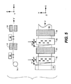
- FIG. 5 is a schematic diagram that shows, from side and top views, a printing path having additional printer components
- FIG. 6 is a schematic diagram showing a constraint pattern for printer components
- FIG. 7 is a perspective view showing an arrangement of alignment mechanisms for printer components in one embodiment
- FIG. 8 is a perspective view from the side showing components of an alignment mechanism in one embodiment
- FIG. 9 is a perspective view that shows a printhead assembly mounted within its frame
- FIG. 10A is a perspective view that shows cross-track adjustments for the printhead assembly of FIG. 9 ;
- FIG. 10B is an enlarged perspective view of a portion of FIG. 10A that shows compliant mounts for the printhead assembly of FIG. 9 ;
- FIG. 10C is a schematic top view of the compliant mounts shown in FIG. 10B ;
- FIG. 11A shows perspective and side views of an example embodiment of a coupling arrangement for an alignment mechanism
- FIG. 11B shows a bottom view of another example embodiment of a coupling arrangement for an alignment mechanism
- FIG. 12 is a cross-sectional view of a joint in one embodiment
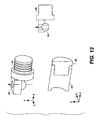
- FIG. 13 shows perspective and cross-sectional views of the joint ends of sections in an alignment mechanism for one embodiment
- FIG. 14 is a perspective view that shows an assembled alignment mechanism within a printer frame assembly.
- FIG. 15 is perspective view showing assembly details for a printer component according to one embodiment.
- continuous web of print media relates to a print media that is in the form of a continuous strip of media as it passes through the printing system from an entrance to an exit thereof.
- the continuous web of print media itself serves as the receiving print medium to which one or more printing ink or inks or other coating liquids are applied in non-contact fashion.
- upstream and downstream are terms of art referring to relative positions along the transport path of a moving web; points on the web move from upstream to downstream. Where they are used, the terms “first”, “second”, and so on, do not necessarily denote any ordinal or priority relation, but are simply used to more clearly distinguish one element from another.
- first module 20 and a second module 40 are provided for guiding continuous web media 60 that originates from a source roller 12 . Following an initial slack loop 52 , the media that is fed from source roller 12 is then directed through digital printing system 10 , past one or more digital printhead assemblies 16 and other printing system 10 components, for example, a dryer 14 .
- first module 20 includes a cross-track positioning mechanism 22 , a tensioning mechanism 24 , and one or more angular constraint structures 26 .
- Second module 40 includes a media turnover mechanism 30 and one or more additional angular constraint structures 26 . After the print media leaves the digital printing system 10 , it travels to a media receiving unit, in this case a take-up roll 18 .
- Other examples of system components include web cleaners, web tension sensors, and quality control sensors.
- a digital printing system 50 includes a considerably longer print path than that shown in FIG. 1 , but provides the same overall sequence of angular constraints with a lateral constraint at A and with a similar overall series of gimbaled, castered, and fixed rollers and supports shown at positions B through N.
- Printing system 50 also includes a turnover module TB.
- Control logic for the appropriate in- and out-feed driver rollers at B and N, respectively, can be provided by an external computer or processor, not shown in FIG. 2 .
- an on-board control logic processor 90 such as a dedicated microprocessor or other logic circuit, is provided for maintaining control of web tension within each tension-setting mechanism and for controlling other machine operation and operator interface functions.
- Printing system 10 and printing system 50 have been described in more detail in at least one of commonly-assigned U.S. patent application Ser. No. 12/627,032 filed Nov. 30, 2009 entitled “MODULAR MEDIA TRANSPORT SYSTEM”, by DeCook et al. or commonly-assigned U.S. patent application Ser. No. 12/627,018 filed Nov. 30, 2009 entitled “MEDIA TRANSPORT SYSTEM FOR NON-CONTACTING PRINTING”, by Muir et al.
- FIG. 3 shows an exploded view of an arrangement of digital printhead assemblies 16 , dryers 14 , and a support apparatus such as one that can be used for module 20 or 40 in the FIG. 2 embodiment.
- An example of a support apparatus includes inspection unit 15 .
- a frame assembly 76 a frame 70 supports a number of pans 72 , mechanically fixed with respect to frame 70 and configured to seat digital printhead assemblies 16 , dryers 14 , rollers 74 , and other components along the print path. Since frame 70 can be a few meters or more in length and dot-to-dot registration for digital printing is measured in microns (10 ⁇ 6 m), some compensation is needed so that frame 70 expansion or contraction with temperature does not noticeably affect printing registration.
- FIG. 4 shows, from side and top views, components in a portion of the printing path for either FIG. 1 or FIG. 2 embodiments.
- cross track alignment for digital printhead assembly 16 must be constrained at a, in the y axis direction.
- rotation or skew shown as angle b, must also be constrained. There are no registration requirements for dryer 14 .
- the schematic diagram of FIG. 5 shows how the registration problem becomes more complex where there are multiple printer components that must be registered to each other, such as for multiple digital printhead assemblies 16 .
- FIG. 6 shows a pattern of constraints that are needed in order to prevent angular skew, as described with reference to angles b 1 and b 2 in FIG. 5 and to provide cross-track constraints (a 1 and a 2 in FIG. 5 ).
- the digital printhead assemblies 16 are joined by the network of constraints. Dryers 14 (which need not be critically aligned), meanwhile, are independent of the constraint arrangement.
- Roller 74 mounted to frame 70 , serves as a first, or reference printer component. Roller 74 is typically located in the media path just prior to the first printhead in the printing zone, such as rollers F in the first module 20 and roller L in the second module 40 shown in FIG. 2 .
- An encoder for tracking or monitoring the motion of the print media, as it moves through the printing system, is commonly employed at roller 74 .
- the print media, moving through the printing system, moves perpendicular to roller as it leaves roller 74 .
- Printhead assembly 16 a is spaced away from roller 74 by beams 82 a and 82 c .
- Beam 82 a is coupled to a first printer component, roller 74 as shown in FIG. 6 , at coupling 84 a and to a second printer component, printhead 16 a as shown in FIG. 6 , at coupling 84 b .
- beam 82 c is coupled to roller 74 at coupling 84 d and to printhead 16 a at coupling 84 e .
- printhead 16 , roller 74 , and beams 82 a and 82 c form the sides of a parallelogram, assuming the couplings lie in a plane.
- the parallelogram can form a rectangle with a properly chosen lateral constraint 88 on printhead 16 a .
- printhead 16 a and printhead 16 b , and beams 82 b and 82 d can be made to form a rectangle.
- roller 74 is described above as being the first printer component and printhead 16 a is described as being the second printer component, these designation are not limited to roller 74 and printhead 16 a .
- printhead 16 a can be referred to as the first printer component and printhead 16 b can be referred to as the second printer component.
- Other designations or configurations of the first printer component and the second printer component are also permitted.
- FIG. 7 show how the constraint pattern of FIG. 6 is provided according to one embodiment.
- Alignment mechanisms 80 and 81 are kinematically coupled to each printer component. In the embodiment shown, the spacing between each printhead assembly 16 defined by elements of the first and second alignment mechanisms 80 and 81 . As both first and second alignment mechanisms 80 and 81 are similarly constructed, the description of alignment mechanism 80 that follows applies equivalently to alignment mechanism 81 , with some possible differences in coupling components, as described subsequently.
- printer component spacing By defining printer component spacing in this manner, sensitivity to stresses on frame 70 is reduced. As such, lighter frame construction (as compared to conventional frame construction) can be used which helps reduce at least manufacturing costs and shipping costs.
- these printer components include roller 74 and four digital printhead assemblies 16 .
- Alignment mechanism 80 has a series of beams or sections 82 joined by couplings 84 that link kinematically to each digital printhead assembly 16 .
- Alignment mechanism 80 is shown as a series of modular assemblies, simplifying the interconnection of printer components in various arrangements and at various distances from each other. Alternately, alignment mechanism 80 can be a continuous structure that extends the length of the printing system, such as the length of frame assembly 76 ( FIG. 3 ).
- the alignment mechanisms 80 and 81 are used to define the spacing between various printer components that are aligned relative to each other, for example, rollers or printhead assemblies. While the alignment mechanisms 80 and 81 are used to define the spacing between various printer components, the alignment mechanisms do not support the printer components.
- the printhead assemblies, dryers, and other components are secured to and supported by other structures, for example, pans 72 as shown in FIG. 3 .
- the printer components are compliantly mounted to frame assemblies 76 that are each secured to one of pans 72 .
- the compliant mount allows the printer component to move freely within a plane.
- An example embodiment of a compliant mount 77 is shown in FIG. 10B and FIG. 10C .
- a printhead assembly base plate which is a portion of a digital printhead assembly, is shown. It has a plurality of receptacles for receiving and securing a plurality of jetting modules (not shown in FIG. 10B ).
- Compliant mounts 77 (flexure structures as shown in FIGS. 10B and 10C ) couple each corner of the base plate to the component support tray 58 .
- L-shaped flexures are shown, though other flexure structures or non-flexure structures can be used as compliant mounts 77 .
- the flexures allow the plate to move freely within the x-y plane, including rotations around the z axis, while impeding motion in z direction.
- the media path can include a plurality of rollers or web guides under the media that cause the media to move along a portion of an arc, as shown in FIG. 2 .
- This concept causing the media to move over a portion of an arc, has also been described in U.S. Pat. No. 6,003,988.
- the orientation of printhead assemblies that print at various locations along the arc tends to vary so that the printhead assembly is oriented approximately parallel to the local plane of the print media.
- the upper surface of the individual pans 72 to which the frame assembly are secured have varying heights and tilt angles.
- the compliant mount 77 of the various printhead assemblies preferably allows each printhead assembly to move freely within the plane parallel to that printhead assembly.
- one of those printer components can be compliantly mounted to allow the component to be free to move in a first plane, while another printer component is free to move in a second plane.
- This allows the spacing between the printheads to be defined by the first and second alignment mechanisms without causing the spacing between a printhead and the print media, passing under it, to be affected by the first and second alignment mechanisms.
- pans 72 include holes 78 through which the beams 82 can pass freely. Because of the overall kinetic mounting arrangement that is used, each printer component is allowed movement within its respective plane P and can be adjusted to a suitable position over its range of movement within its plane P. As shown in FIG. 7 , the respective plane for one printer component may not be in parallel with the plane of another. Portions of pan structure 72 , for example, pan ledges 110 (shown in FIG. 15 ) serve as shields that shield alignment mechanisms 80 and 81 from heat sources, for example, dryers 14 . This shielding helps to reduce the thermal expansion variations that can be caused by dryers 14 .
- FIG. 8 shows couplings 84 of alignment mechanism 80 in more detail.
- the pans 72 and portions of the frame assembly 76 have been omitted to enable the coupling 84 between the printer components (printhead assembly base plates in this figure) to be seen with more clarity.
- Couplings 84 are attached to the printhead assemblies 16 .
- the couplings 84 link to sections 82 of the alignment mechanism 80 .
- Coupling 84 a is shown linking to both an upstream section 82 a and a downstream section 82 b .
- Coupling 84 b is linked only to an upstream section 82 b ; this corresponds to the coupling for the final printhead assembly in a printer module.
- FIG. 9 shows the constraint pattern that applies for compliant mounting of digital printhead assembly 16 within the frame using coupling 84 as part of alignment mechanism 80 and coupling 85 as part of alignment mechanism 81 .
- coupling 84 is an adjustable coupling 120 .
- the upper portion 121 of the coupling is secured to the printhead assembly 16 , and the arm 128 gets coupled to the alignment mechanism 80 .
- the arm 128 is connected to the upper portion 121 by means of flexures 122 .
- An adjustment mechanism 68 shown here as a screw, moves the end of level 104 .
- Lever 124 pivots around fulcrum 126 .
- this adjustment mechanism provides a 3 to 1 displacement ratio between the tip of the lever 124 at the adjustment mechanism and displacement of the arm 128
- clamping plate 132 shown in FIG. 13
- the adjustable coupling 120 is available in order to adjust the angular orientation of digital printhead assembly 16 provided by an adjustment mechanism 68 ; coupling 85 is not adjustable in this embodiment.
- a ball plate arrangement is used to seat digital printhead assembly 16 to tray 58 without overconstraint.
- FIG. 10A shows an adjustment mechanism to provide an adjustment of the cross track position, y-direction position.
- an adjustment mechanism 64 shown here as a screw threaded into block 56 on the component support tray 58 , pushes against the printhead assembly 16 provided to allow adjustment of cross-track position in the y direction.
- adjustment mechanism 64 is a screw, it is preferably a differential screw to provide a high resolution adjustment means.
- Flexure coupling 88 allows serves as a lateral constraint for the printhead assembly 16 relative to the component support tray 58 and the frame assembly 76 to which the component support tray 58 is secured. (shown in FIG. 3 ). Flexure coupling 88 , while providing a lateral constraint on the printhead assembly does not constrain the printhead in the in-track or x axis direction. The flexure coupling 88 should be made sufficiently long so that motion in the x direction over the expected range does not produce unacceptable shifts in the y direction position.
- Manipulation of either or both of adjustment mechanism 64 and adjustment mechanism 68 can be accomplished manually or in an automated manner. When manipulation of either or both of adjustment mechanism 64 and adjustment mechanism 68 is accomplished in an automated fashion, it can occur automatically in response to a change in operating conditions or in response to signals sent by a device that monitors an aspect of the printing operation, for example, print registration, as described in German Patent Application No. 102009039444.3, filed Aug. 31, 2009, entitled “ADAPTIVE STITCH METHOD”, by Schluenss et al.
- FIG. 11A shows perspective and side views of an example embodiment of joints 92 and 94 for each coupling 84 .
- FIG. 11B shows a bottom view of another example embodiment of joints 92 and 94 for each coupling 84 .
- fasteners 108 represented by arrows in this figure
- bolts of joints 92 and 94 are located in the xz plane and are substantially perpendicular to frame 70 (see, for example, FIG. 7 ).
- This configuration of joints 92 and 94 permits rotation of sections 82 of alignment mechanisms 80 and 81 about the z axis and some rotation about the y axis.
- FIG. 11A shows perspective and side views of an example embodiment of joints 92 and 94 for each coupling 84 .
- FIG. 11B shows a bottom view of another example embodiment of joints 92 and 94 for each coupling 84 .
- fasteners 108 represented by arrows in this figure
- bolts for example, bolts
- joints 92 and 94 and coupling 84 have been rotated 90 degrees relative to each other as compared to their respective locations as shown in FIG. 11A .
- coupling 84 extends into the figure.
- Fasteners 108 represented by arrows in this figure
- bolts of joints 92 and 94 are located in the xy plane and are substantially parallel to frame 70 (see, for example, FIG. 7 ).
- This orientation of joints 92 and 94 permits some rotation about the z axis and increased rotation of sections 82 of alignment mechanisms 80 and 81 about the y axis when compared to the orientation of joints 92 and 94 as shown in FIG. 11A and is well suited for implementation in a printing system that includes an arced media path (see, for example, FIG. 2 ).
- FIG. 12 shows an example embodiment of joint 92 or joint 94 that includes, for example, a ball joint 96 that is loaded with a spring 98 .
- the end of section 82 includes a cap 46 .
- Cap 46 has an arm 100 with a tapered recess 102 for engaging ball 96 .
- Coupling 84 also has an arm 104 with a similar tapered recess 106 for engaging ball 96 .
- the joint is held together with a fastener 108 , for example, a bolt, that passes through clearance holes in arm 104 and ball 96 and is screwed into arm 100 .
- arm 100 can also have a clearance hole for the fastener 108 , and a nut, or another type of fastener retaining mechanism, can be used to secure the fastener in place.
- Spring 98 constrained between the head of fastener 108 and arm 104 , holds the tapered recesses 102 and 106 of arms 100 and 104 firmly in contact with ball 96 .
- This joint provides a kinematic coupling between the coupling 84 and section 82 , having zero backlash between the sections 82 and the coupling 84 while allowing the section 82 to pivot freely, within a range of angles, relative to the coupling 84 .
- FIG. 13 shows perspective and cross-sectional views of the joint ends of sections 82 in one embodiment.
- a cap 46 is glued or otherwise fitted and secured onto the end of a tube 48 .
- the material composition of tube 48 preferably has a low coefficient of thermal expansion (CTE).
- first and second alignment mechanisms use tubes 48 of a commercially available carbon fiber composite material with a coefficient of thermal expansion in a range of less than 5 ppm per degree Celsius, preferably less than or equal to 1.1 ppm per degree Celsius. Alternately, other types of tubing or cable can be used.
- sections 82 use beams formed using tube 48 of the same material, the printer components that are mounted to alignment mechanisms 80 and 81 within the equipment frame behave similarly in response to a change in temperature, moving together in a predictable fashion. Thickness and other dimensions for sections 82 can be different or can be substantially equal.
- FIG. 14 shows an assembled alignment mechanism 80 in one embodiment of the present invention.
- the frame assembly 76 that supports printheads 16 , dryers 14 , roller 74 and inspection unit 15 has been hidden to enable the connection between the printhead units 16 and alignment mechanisms 80 and 81 .
- a first printer component, roller 74 is mounted to frame assembly 76 .
- Alignment mechanisms 80 and 81 are then kinematically coupled to roller 74 and to each of the digital printhead assemblies 16 .
- additional shielding can be used to protect portions of alignment mechanisms 80 and 81 from heat sources.
- each digital printhead assembly 16 is allowed a measure of movement within its plane P, as was shown in FIG. 7 .
- FIG. 15 shows assembly details for seating digital printhead assembly 16 , with its couplings 84 and 85 , within pan 72 .
- Tab fittings 102 and 104 are provided along edges of pan 72 as guides for seating digital printhead assembly 16 . These features help to provide an initial coarse alignment, for printhead positioning.
- Component support tray 58 is secured to pan 72 which forms frame assembly 76 along with frame 70 . As such, any one or a combination of component support tray 58 , pan 72 , frame 70 , or frame assembly 76 can be considered the frame of the printing system.
- each of the first and second printer components are printheads 16
- each is compliantly mounted to a component support tray 58 that is secured to frame assembly 76 . It can be said then that each of the first and second printer components are compliantly mounted to any one or a combination of component support tray 58 , pan 72 , frame 70 , or frame assembly 76 .
- the present invention can be used for multi-color printing, where each digital printhead assembly 16 provides a different colorant, such as a cyan, yellow, magenta, or black colorant, for example.
- a different colorant such as a cyan, yellow, magenta, or black colorant, for example.
- the present invention can be used for single color printing.
- the present invention can be used in conjunction with a timing subsystem that measures the precise position of the printed dots and adjusts timing at various digital printhead assemblies 16 .
Abstract
Description
-
- 10. Printing system
- 12. Source roller
- 14. Dryer
- 15. Inspection Unit
- 16. Digital printhead assembly
- 18. Take-up roll
- 20. Module
- 22. Cross-track positioning mechanism
- 24. Tensioning mechanism
- 26. Constraint structure
- 30. Turnover mechanism
- 40. Module
- 44. Extended section
- 46. Cap
- 48. Tube
- 50. Digital printing system
- 52. Slack loop
- 58. Component support tray
- 60. Web media
- 64. Adjustment mechanism
- 68. Adjustment mechanism
- 70. Frame
- 72. Pan
- 74. Roller
- 76. Frame assembly
- 77 Compliant mount
- 78. Hole
- 80, 81. Alignment mechanism
- 82. Section
- 84, 85. Coupling
- 86, 87. Ball joint
- 88. Coupling
- 90. Control logic processor
- 92, 94. Joint
- 96. Ball joint
- 98. Spring
- 100. Arm
- 102. Recess
- 104. Arm
- 106. Recess
- 108. Fastener
- 110. Pan ledge
- 120 Adjustable coupling
- 121 Upper portion
- 122 Flexure
- 124 Lever
- 106 Fulcrum
- 128 Arm
- 130 Flexure
- 132 Clamping plate
Claims (20)
Priority Applications (6)
| Application Number | Priority Date | Filing Date | Title |
|---|---|---|---|
| US12/712,296 US8770106B2 (en) | 2010-02-25 | 2010-02-25 | Printer component mounting and alignment system |
| BR112012019688A BR112012019688A2 (en) | 2010-02-25 | 2011-02-10 | printing system |
| EP11705115.1A EP2539153B1 (en) | 2010-02-25 | 2011-02-10 | Printer component mounting and alignment system |
| CN201180010795.9A CN102770276B (en) | 2010-02-25 | 2011-02-10 | Printer component mounting and alignment system |
| JP2012555024A JP2013520338A (en) | 2010-02-25 | 2011-02-10 | Printer component mounting and alignment system |
| PCT/US2011/024306 WO2011106164A1 (en) | 2010-02-25 | 2011-02-10 | Printer component mounting and alignment system |
Applications Claiming Priority (1)
| Application Number | Priority Date | Filing Date | Title |
|---|---|---|---|
| US12/712,296 US8770106B2 (en) | 2010-02-25 | 2010-02-25 | Printer component mounting and alignment system |
Publications (2)
| Publication Number | Publication Date |
|---|---|
| US20110203471A1 US20110203471A1 (en) | 2011-08-25 |
| US8770106B2 true US8770106B2 (en) | 2014-07-08 |
Family
ID=44010101
Family Applications (1)
| Application Number | Title | Priority Date | Filing Date |
|---|---|---|---|
| US12/712,296 Expired - Fee Related US8770106B2 (en) | 2010-02-25 | 2010-02-25 | Printer component mounting and alignment system |
Country Status (6)
| Country | Link |
|---|---|
| US (1) | US8770106B2 (en) |
| EP (1) | EP2539153B1 (en) |
| JP (1) | JP2013520338A (en) |
| CN (1) | CN102770276B (en) |
| BR (1) | BR112012019688A2 (en) |
| WO (1) | WO2011106164A1 (en) |
Cited By (2)
| Publication number | Priority date | Publication date | Assignee | Title |
|---|---|---|---|---|
| US20140168302A1 (en) * | 2012-12-19 | 2014-06-19 | Vistaprint Technologies Limited | System and method for offline print head alignment |
| US9259931B2 (en) | 2012-12-19 | 2016-02-16 | Cimpress Schweiz Gmbh | System and method for print head alignment using alignment adapter |
Families Citing this family (9)
| Publication number | Priority date | Publication date | Assignee | Title |
|---|---|---|---|---|
| TWI464070B (en) * | 2011-12-16 | 2014-12-11 | Cal Comp Electronics & Comm Co | Driven roller unit and paper feeding device |
| US9199498B2 (en) | 2013-11-21 | 2015-12-01 | Eastman Kodak Company | Inkjet printing method and apparatus with feedback control |
| RU2585703C2 (en) * | 2014-04-21 | 2016-06-10 | Александр Александрович Титов | Three-dimensional printer (versions) |
| US10016993B2 (en) * | 2016-05-24 | 2018-07-10 | Electronics For Imaging, Inc. | Elastic bending mechanism for bi-directional adjustment of print head position |
| CN206718727U (en) * | 2017-01-19 | 2017-12-08 | 广州晶绘实业有限公司 | A kind of common platform printer organization of more main frames |
| JP6864927B2 (en) * | 2017-02-08 | 2021-04-28 | グァンジョウ クリスタルジェット インダストリー カンパニー リミテッドGuangzhou Crystaljet Industry Co., Ltd. | Printer mechanism in which multiple main units use a common platform |
| DE102018202658A1 (en) * | 2017-03-27 | 2018-09-27 | Heidelberger Druckmaschinen Ag | Method for inserting an ink print head into a holder |
| CN113165377B (en) * | 2018-12-13 | 2022-07-08 | 伊斯曼柯达公司 | Low volume flexographic and gravure inking systems |
| CN113427916A (en) * | 2021-06-28 | 2021-09-24 | 广州市普理司科技有限公司 | Digital printing machine |
Citations (17)
| Publication number | Priority date | Publication date | Assignee | Title |
|---|---|---|---|---|
| EP0729844A1 (en) | 1995-03-02 | 1996-09-04 | Hewlett-Packard Company | Dual inkjet pen carriage system |
| US6003988A (en) | 1997-12-23 | 1999-12-21 | Scitex Digital Printing, Inc. | Printer architecture |
| US6015209A (en) | 1995-04-27 | 2000-01-18 | Hewlett-Packard Company | Replaceable ink container with fluid interconnect for coupling to an ink-jet printer |
| US6412990B1 (en) * | 1999-11-30 | 2002-07-02 | Eastman Kodak Company | Method and apparatus for photofinishing a photosensitive media and/or ordering of imaging products |
| US20020157555A1 (en) * | 2001-01-08 | 2002-10-31 | Smith Daniel E. | Printing system web guide coupling assembly |
| US20020192001A1 (en) * | 1999-11-30 | 2002-12-19 | Mcintyre Dale F. | Method and apparatus for making an album page |
| US6516688B2 (en) * | 1995-06-07 | 2003-02-11 | David V. Albertson | Hand tool |
| US6659602B2 (en) * | 2001-02-08 | 2003-12-09 | Miyakoshi Printing Machinery Co., Ltd. | Ink-jet printer arrangement for printing both sides of a web |
| US20040135857A1 (en) | 2002-11-26 | 2004-07-15 | Kazuhiro Hashii | Ink cartridge and recording apparatus |
| EP1447226A1 (en) | 2003-02-14 | 2004-08-18 | Samsung Electronics Co., Ltd. | Calibrating alignment errors |
| US6857803B2 (en) * | 2001-01-08 | 2005-02-22 | Vutek, Inc. | Printing system web guide with a removable platen |
| US20060072001A1 (en) * | 2004-09-27 | 2006-04-06 | Klein Rudolph J | Thermal and inkjet printer |
| US20090189929A1 (en) * | 2008-01-25 | 2009-07-30 | Kabushiki Kaisha Tokyo Kikai Seisakusho | Continuous paper web duplex inkjet printing unit |
| WO2009145870A1 (en) | 2008-05-28 | 2009-12-03 | Eastman Kodak Company | Jetting module installation and alignment apparatus |
| US20100188468A1 (en) * | 2008-12-17 | 2010-07-29 | E.C.H. Will Gmbh | Apparatus for imprinting a sheet web |
| US8205984B2 (en) * | 2009-09-29 | 2012-06-26 | Hewlett-Packard Development Company, L.P. | Web printer and support structure |
| US8226224B2 (en) * | 2009-09-11 | 2012-07-24 | Hewlett-Packard Development Company, L.P. | Inkjet web printer |
Family Cites Families (3)
| Publication number | Priority date | Publication date | Assignee | Title |
|---|---|---|---|---|
| ATE221457T1 (en) * | 1997-05-29 | 2002-08-15 | Kba Giori Sa | WIPER CYLINDER DRIVE OF A ROUGH PRINTING MACHINE |
| ES2263733T3 (en) * | 1998-03-04 | 2006-12-16 | Hewlett-Packard Company | INK CARTRIDGE RECONDITIONING SYSTEM. |
| DE10161400A1 (en) * | 2001-12-13 | 2003-06-18 | Roland Man Druckmasch | Cam gear on a folding cylinder |
-
2010
- 2010-02-25 US US12/712,296 patent/US8770106B2/en not_active Expired - Fee Related
-
2011
- 2011-02-10 JP JP2012555024A patent/JP2013520338A/en not_active Withdrawn
- 2011-02-10 EP EP11705115.1A patent/EP2539153B1/en not_active Not-in-force
- 2011-02-10 CN CN201180010795.9A patent/CN102770276B/en not_active Expired - Fee Related
- 2011-02-10 BR BR112012019688A patent/BR112012019688A2/en not_active Application Discontinuation
- 2011-02-10 WO PCT/US2011/024306 patent/WO2011106164A1/en active Application Filing
Patent Citations (18)
| Publication number | Priority date | Publication date | Assignee | Title |
|---|---|---|---|---|
| EP0729844A1 (en) | 1995-03-02 | 1996-09-04 | Hewlett-Packard Company | Dual inkjet pen carriage system |
| US6015209A (en) | 1995-04-27 | 2000-01-18 | Hewlett-Packard Company | Replaceable ink container with fluid interconnect for coupling to an ink-jet printer |
| US6516688B2 (en) * | 1995-06-07 | 2003-02-11 | David V. Albertson | Hand tool |
| US6003988A (en) | 1997-12-23 | 1999-12-21 | Scitex Digital Printing, Inc. | Printer architecture |
| US6412990B1 (en) * | 1999-11-30 | 2002-07-02 | Eastman Kodak Company | Method and apparatus for photofinishing a photosensitive media and/or ordering of imaging products |
| US20020192001A1 (en) * | 1999-11-30 | 2002-12-19 | Mcintyre Dale F. | Method and apparatus for making an album page |
| US6857803B2 (en) * | 2001-01-08 | 2005-02-22 | Vutek, Inc. | Printing system web guide with a removable platen |
| US20020157555A1 (en) * | 2001-01-08 | 2002-10-31 | Smith Daniel E. | Printing system web guide coupling assembly |
| US6659602B2 (en) * | 2001-02-08 | 2003-12-09 | Miyakoshi Printing Machinery Co., Ltd. | Ink-jet printer arrangement for printing both sides of a web |
| US20040135857A1 (en) | 2002-11-26 | 2004-07-15 | Kazuhiro Hashii | Ink cartridge and recording apparatus |
| EP1447226A1 (en) | 2003-02-14 | 2004-08-18 | Samsung Electronics Co., Ltd. | Calibrating alignment errors |
| US20060072001A1 (en) * | 2004-09-27 | 2006-04-06 | Klein Rudolph J | Thermal and inkjet printer |
| US20090189929A1 (en) * | 2008-01-25 | 2009-07-30 | Kabushiki Kaisha Tokyo Kikai Seisakusho | Continuous paper web duplex inkjet printing unit |
| WO2009145870A1 (en) | 2008-05-28 | 2009-12-03 | Eastman Kodak Company | Jetting module installation and alignment apparatus |
| US20090295878A1 (en) * | 2008-05-28 | 2009-12-03 | Hanchak Michael S | Jetting module installation and alignment apparatus |
| US20100188468A1 (en) * | 2008-12-17 | 2010-07-29 | E.C.H. Will Gmbh | Apparatus for imprinting a sheet web |
| US8226224B2 (en) * | 2009-09-11 | 2012-07-24 | Hewlett-Packard Development Company, L.P. | Inkjet web printer |
| US8205984B2 (en) * | 2009-09-29 | 2012-06-26 | Hewlett-Packard Development Company, L.P. | Web printer and support structure |
Non-Patent Citations (3)
| Title |
|---|
| German Patent Application No. 102009039444.3 filed Aug. 31, 2009 entitled "Adaptive Stitch Method", by Schluenss et al. |
| U.S. Appl. No. 12/627,018, filed Nov. 30, 2009 entitled "Media Transport System for Non-Contacting Printing" by Muir et al. |
| U.S. Appl. No. 12/627,032, filed Nov. 30, 2009, entitled "Modular Media Transport System" by DeCook et al. |
Cited By (4)
| Publication number | Priority date | Publication date | Assignee | Title |
|---|---|---|---|---|
| US20140168302A1 (en) * | 2012-12-19 | 2014-06-19 | Vistaprint Technologies Limited | System and method for offline print head alignment |
| US9132660B2 (en) * | 2012-12-19 | 2015-09-15 | Cimpress Schweiz Gmbh | System and method for offline print head alignment |
| US9259931B2 (en) | 2012-12-19 | 2016-02-16 | Cimpress Schweiz Gmbh | System and method for print head alignment using alignment adapter |
| US9782966B2 (en) | 2012-12-19 | 2017-10-10 | Cimpress Schweiz Gmbh | System and method for print head alignment using alignment adapter |
Also Published As
| Publication number | Publication date |
|---|---|
| JP2013520338A (en) | 2013-06-06 |
| BR112012019688A2 (en) | 2016-05-03 |
| EP2539153A1 (en) | 2013-01-02 |
| WO2011106164A1 (en) | 2011-09-01 |
| CN102770276B (en) | 2014-11-19 |
| EP2539153B1 (en) | 2014-12-31 |
| CN102770276A (en) | 2012-11-07 |
| US20110203471A1 (en) | 2011-08-25 |
Similar Documents
| Publication | Publication Date | Title |
|---|---|---|
| US8770106B2 (en) | Printer component mounting and alignment system | |
| KR102165979B1 (en) | Modular print bar assembly for an inkjet printer | |
| US7100510B2 (en) | Method for registering patterns on a web | |
| KR20140079707A (en) | Improved image quality by printing frequency adjustment using belt surface velocity measurement | |
| US20130050763A1 (en) | Multiple sided media pattern registration system | |
| US8931877B1 (en) | Method and apparatus for controlling printhead motion with a friction track ball | |
| JP2011156806A (en) | Head attachment member, liquid ejection device, and head attachment method | |
| US8500234B2 (en) | Registering patterns on multiple media sides | |
| US7650839B2 (en) | Method for registering patterns on a web | |
| US8662623B2 (en) | Printing registered patterns on multiple media sides | |
| US9193192B1 (en) | Reducing print artifacts using isolated tension zones | |
| US8632153B2 (en) | Printing system having multiple sided pattern registration | |
| WO2015186592A1 (en) | Inkjet recording device | |
| US9010924B2 (en) | System and method for aligning duplex images using alignment marks | |
| US9278559B1 (en) | Reducing tension fluctuations using isolated tension zones | |
| JP2015182364A (en) | Inspection chart and printer | |
| US20150239234A1 (en) | System for reducing tension fluctuations on a web | |
| US9296228B2 (en) | Reducing tension fluctuations using isolated tension zones | |
| JP7417939B2 (en) | Stage equipment and printing equipment | |
| US20150239231A1 (en) | Method for reducing artifacts using tension control | |
| JP6519843B2 (en) | Recording unit discharge position adjustment device, image forming apparatus, and recording unit position correction method | |
| EP4296065A1 (en) | A method for fine adjustment of the position of ink drops printed by at least one printing head of a printing device and printing device | |
| US20150239232A1 (en) | System for reducing artifacts using tension control | |
| US20150239233A1 (en) | Method for reducing tension fluctuations on a web | |
| US9180705B1 (en) | Reducing print artifacts using isolated tension zones |
Legal Events
| Date | Code | Title | Description |
|---|---|---|---|
| AS | Assignment |
Owner name: EASTMAN KODAK COMPANY, NEW YORK Free format text: ASSIGNMENT OF ASSIGNORS INTEREST;ASSIGNORS:MUIR, CHRISTOPHER M.;DASSERO, WILLIAM F.;JAMES, MARTIN C.;AND OTHERS;SIGNING DATES FROM 20100414 TO 20100503;REEL/FRAME:024350/0940 |
|
| AS | Assignment |
Owner name: CITICORP NORTH AMERICA, INC., AS AGENT, NEW YORK Free format text: SECURITY INTEREST;ASSIGNORS:EASTMAN KODAK COMPANY;PAKON, INC.;REEL/FRAME:028201/0420 Effective date: 20120215 |
|
| AS | Assignment |
Owner name: WILMINGTON TRUST, NATIONAL ASSOCIATION, AS AGENT, Free format text: PATENT SECURITY AGREEMENT;ASSIGNORS:EASTMAN KODAK COMPANY;PAKON, INC.;REEL/FRAME:030122/0235 Effective date: 20130322 Owner name: WILMINGTON TRUST, NATIONAL ASSOCIATION, AS AGENT, MINNESOTA Free format text: PATENT SECURITY AGREEMENT;ASSIGNORS:EASTMAN KODAK COMPANY;PAKON, INC.;REEL/FRAME:030122/0235 Effective date: 20130322 |
|
| AS | Assignment |
Owner name: BARCLAYS BANK PLC, AS ADMINISTRATIVE AGENT, NEW YORK Free format text: INTELLECTUAL PROPERTY SECURITY AGREEMENT (SECOND LIEN);ASSIGNORS:EASTMAN KODAK COMPANY;FAR EAST DEVELOPMENT LTD.;FPC INC.;AND OTHERS;REEL/FRAME:031159/0001 Effective date: 20130903 Owner name: JPMORGAN CHASE BANK, N.A., AS ADMINISTRATIVE, DELAWARE Free format text: INTELLECTUAL PROPERTY SECURITY AGREEMENT (FIRST LIEN);ASSIGNORS:EASTMAN KODAK COMPANY;FAR EAST DEVELOPMENT LTD.;FPC INC.;AND OTHERS;REEL/FRAME:031158/0001 Effective date: 20130903 Owner name: JPMORGAN CHASE BANK, N.A., AS ADMINISTRATIVE, DELA Free format text: INTELLECTUAL PROPERTY SECURITY AGREEMENT (FIRST LIEN);ASSIGNORS:EASTMAN KODAK COMPANY;FAR EAST DEVELOPMENT LTD.;FPC INC.;AND OTHERS;REEL/FRAME:031158/0001 Effective date: 20130903 Owner name: BARCLAYS BANK PLC, AS ADMINISTRATIVE AGENT, NEW YO Free format text: INTELLECTUAL PROPERTY SECURITY AGREEMENT (SECOND LIEN);ASSIGNORS:EASTMAN KODAK COMPANY;FAR EAST DEVELOPMENT LTD.;FPC INC.;AND OTHERS;REEL/FRAME:031159/0001 Effective date: 20130903 Owner name: EASTMAN KODAK COMPANY, NEW YORK Free format text: RELEASE OF SECURITY INTEREST IN PATENTS;ASSIGNORS:CITICORP NORTH AMERICA, INC., AS SENIOR DIP AGENT;WILMINGTON TRUST, NATIONAL ASSOCIATION, AS JUNIOR DIP AGENT;REEL/FRAME:031157/0451 Effective date: 20130903 Owner name: PAKON, INC., NEW YORK Free format text: RELEASE OF SECURITY INTEREST IN PATENTS;ASSIGNORS:CITICORP NORTH AMERICA, INC., AS SENIOR DIP AGENT;WILMINGTON TRUST, NATIONAL ASSOCIATION, AS JUNIOR DIP AGENT;REEL/FRAME:031157/0451 Effective date: 20130903 Owner name: BANK OF AMERICA N.A., AS AGENT, MASSACHUSETTS Free format text: INTELLECTUAL PROPERTY SECURITY AGREEMENT (ABL);ASSIGNORS:EASTMAN KODAK COMPANY;FAR EAST DEVELOPMENT LTD.;FPC INC.;AND OTHERS;REEL/FRAME:031162/0117 Effective date: 20130903 |
|
| FEPP | Fee payment procedure |
Free format text: PAYER NUMBER DE-ASSIGNED (ORIGINAL EVENT CODE: RMPN); ENTITY STATUS OF PATENT OWNER: LARGE ENTITY Free format text: PAYOR NUMBER ASSIGNED (ORIGINAL EVENT CODE: ASPN); ENTITY STATUS OF PATENT OWNER: LARGE ENTITY |
|
| FEPP | Fee payment procedure |
Free format text: MAINTENANCE FEE REMINDER MAILED (ORIGINAL EVENT CODE: REM.) |
|
| LAPS | Lapse for failure to pay maintenance fees |
Free format text: PATENT EXPIRED FOR FAILURE TO PAY MAINTENANCE FEES (ORIGINAL EVENT CODE: EXP.) |
|
| STCH | Information on status: patent discontinuation |
Free format text: PATENT EXPIRED DUE TO NONPAYMENT OF MAINTENANCE FEES UNDER 37 CFR 1.362 |
|
| FP | Lapsed due to failure to pay maintenance fee |
Effective date: 20180708 |
|
| AS | Assignment |
Owner name: PAKON, INC., NEW YORK Free format text: RELEASE BY SECURED PARTY;ASSIGNOR:JP MORGAN CHASE BANK, N.A., AS ADMINISTRATIVE AGENT;REEL/FRAME:050239/0001 Effective date: 20190617 Owner name: CREO MANUFACTURING AMERICA LLC, NEW YORK Free format text: RELEASE BY SECURED PARTY;ASSIGNOR:JP MORGAN CHASE BANK, N.A., AS ADMINISTRATIVE AGENT;REEL/FRAME:050239/0001 Effective date: 20190617 Owner name: KODAK (NEAR EAST), INC., NEW YORK Free format text: RELEASE BY SECURED PARTY;ASSIGNOR:JP MORGAN CHASE BANK, N.A., AS ADMINISTRATIVE AGENT;REEL/FRAME:050239/0001 Effective date: 20190617 Owner name: FPC, INC., NEW YORK Free format text: RELEASE BY SECURED PARTY;ASSIGNOR:JP MORGAN CHASE BANK, N.A., AS ADMINISTRATIVE AGENT;REEL/FRAME:050239/0001 Effective date: 20190617 Owner name: EASTMAN KODAK COMPANY, NEW YORK Free format text: RELEASE BY SECURED PARTY;ASSIGNOR:JP MORGAN CHASE BANK, N.A., AS ADMINISTRATIVE AGENT;REEL/FRAME:050239/0001 Effective date: 20190617 Owner name: KODAK AVIATION LEASING LLC, NEW YORK Free format text: RELEASE BY SECURED PARTY;ASSIGNOR:JP MORGAN CHASE BANK, N.A., AS ADMINISTRATIVE AGENT;REEL/FRAME:050239/0001 Effective date: 20190617 Owner name: KODAK PHILIPPINES, LTD., NEW YORK Free format text: RELEASE BY SECURED PARTY;ASSIGNOR:JP MORGAN CHASE BANK, N.A., AS ADMINISTRATIVE AGENT;REEL/FRAME:050239/0001 Effective date: 20190617 Owner name: QUALEX, INC., NEW YORK Free format text: RELEASE BY SECURED PARTY;ASSIGNOR:JP MORGAN CHASE BANK, N.A., AS ADMINISTRATIVE AGENT;REEL/FRAME:050239/0001 Effective date: 20190617 Owner name: KODAK IMAGING NETWORK, INC., NEW YORK Free format text: RELEASE BY SECURED PARTY;ASSIGNOR:JP MORGAN CHASE BANK, N.A., AS ADMINISTRATIVE AGENT;REEL/FRAME:050239/0001 Effective date: 20190617 Owner name: FAR EAST DEVELOPMENT LTD., NEW YORK Free format text: RELEASE BY SECURED PARTY;ASSIGNOR:JP MORGAN CHASE BANK, N.A., AS ADMINISTRATIVE AGENT;REEL/FRAME:050239/0001 Effective date: 20190617 Owner name: KODAK AMERICAS, LTD., NEW YORK Free format text: RELEASE BY SECURED PARTY;ASSIGNOR:JP MORGAN CHASE BANK, N.A., AS ADMINISTRATIVE AGENT;REEL/FRAME:050239/0001 Effective date: 20190617 Owner name: NPEC, INC., NEW YORK Free format text: RELEASE BY SECURED PARTY;ASSIGNOR:JP MORGAN CHASE BANK, N.A., AS ADMINISTRATIVE AGENT;REEL/FRAME:050239/0001 Effective date: 20190617 Owner name: LASER PACIFIC MEDIA CORPORATION, NEW YORK Free format text: RELEASE BY SECURED PARTY;ASSIGNOR:JP MORGAN CHASE BANK, N.A., AS ADMINISTRATIVE AGENT;REEL/FRAME:050239/0001 Effective date: 20190617 Owner name: KODAK PORTUGUESA LIMITED, NEW YORK Free format text: RELEASE BY SECURED PARTY;ASSIGNOR:JP MORGAN CHASE BANK, N.A., AS ADMINISTRATIVE AGENT;REEL/FRAME:050239/0001 Effective date: 20190617 Owner name: KODAK REALTY, INC., NEW YORK Free format text: RELEASE BY SECURED PARTY;ASSIGNOR:JP MORGAN CHASE BANK, N.A., AS ADMINISTRATIVE AGENT;REEL/FRAME:050239/0001 Effective date: 20190617 |
|
| AS | Assignment |
Owner name: KODAK REALTY, INC., NEW YORK Free format text: RELEASE BY SECURED PARTY;ASSIGNOR:JP MORGAN CHASE BANK, N.A., AS ADMINISTRATIVE AGENT;REEL/FRAME:049901/0001 Effective date: 20190617 Owner name: KODAK IMAGING NETWORK, INC., NEW YORK Free format text: RELEASE BY SECURED PARTY;ASSIGNOR:JP MORGAN CHASE BANK, N.A., AS ADMINISTRATIVE AGENT;REEL/FRAME:049901/0001 Effective date: 20190617 Owner name: CREO MANUFACTURING AMERICA LLC, NEW YORK Free format text: RELEASE BY SECURED PARTY;ASSIGNOR:JP MORGAN CHASE BANK, N.A., AS ADMINISTRATIVE AGENT;REEL/FRAME:049901/0001 Effective date: 20190617 Owner name: QUALEX, INC., NEW YORK Free format text: RELEASE BY SECURED PARTY;ASSIGNOR:JP MORGAN CHASE BANK, N.A., AS ADMINISTRATIVE AGENT;REEL/FRAME:049901/0001 Effective date: 20190617 Owner name: PAKON, INC., NEW YORK Free format text: RELEASE BY SECURED PARTY;ASSIGNOR:JP MORGAN CHASE BANK, N.A., AS ADMINISTRATIVE AGENT;REEL/FRAME:049901/0001 Effective date: 20190617 Owner name: KODAK (NEAR EAST), INC., NEW YORK Free format text: RELEASE BY SECURED PARTY;ASSIGNOR:JP MORGAN CHASE BANK, N.A., AS ADMINISTRATIVE AGENT;REEL/FRAME:049901/0001 Effective date: 20190617 Owner name: PFC, INC., NEW YORK Free format text: RELEASE BY SECURED PARTY;ASSIGNOR:JP MORGAN CHASE BANK, N.A., AS ADMINISTRATIVE AGENT;REEL/FRAME:049901/0001 Effective date: 20190617 Owner name: NPEC, INC., NEW YORK Free format text: RELEASE BY SECURED PARTY;ASSIGNOR:JP MORGAN CHASE BANK, N.A., AS ADMINISTRATIVE AGENT;REEL/FRAME:049901/0001 Effective date: 20190617 Owner name: FAR EAST DEVELOPMENT LTD., NEW YORK Free format text: RELEASE BY SECURED PARTY;ASSIGNOR:JP MORGAN CHASE BANK, N.A., AS ADMINISTRATIVE AGENT;REEL/FRAME:049901/0001 Effective date: 20190617 Owner name: KODAK AMERICAS, LTD., NEW YORK Free format text: RELEASE BY SECURED PARTY;ASSIGNOR:JP MORGAN CHASE BANK, N.A., AS ADMINISTRATIVE AGENT;REEL/FRAME:049901/0001 Effective date: 20190617 Owner name: KODAK AVIATION LEASING LLC, NEW YORK Free format text: RELEASE BY SECURED PARTY;ASSIGNOR:JP MORGAN CHASE BANK, N.A., AS ADMINISTRATIVE AGENT;REEL/FRAME:049901/0001 Effective date: 20190617 Owner name: LASER PACIFIC MEDIA CORPORATION, NEW YORK Free format text: RELEASE BY SECURED PARTY;ASSIGNOR:JP MORGAN CHASE BANK, N.A., AS ADMINISTRATIVE AGENT;REEL/FRAME:049901/0001 Effective date: 20190617 Owner name: KODAK PORTUGUESA LIMITED, NEW YORK Free format text: RELEASE BY SECURED PARTY;ASSIGNOR:JP MORGAN CHASE BANK, N.A., AS ADMINISTRATIVE AGENT;REEL/FRAME:049901/0001 Effective date: 20190617 Owner name: EASTMAN KODAK COMPANY, NEW YORK Free format text: RELEASE BY SECURED PARTY;ASSIGNOR:JP MORGAN CHASE BANK, N.A., AS ADMINISTRATIVE AGENT;REEL/FRAME:049901/0001 Effective date: 20190617 Owner name: KODAK PHILIPPINES, LTD., NEW YORK Free format text: RELEASE BY SECURED PARTY;ASSIGNOR:JP MORGAN CHASE BANK, N.A., AS ADMINISTRATIVE AGENT;REEL/FRAME:049901/0001 Effective date: 20190617 |
|
| AS | Assignment |
Owner name: QUALEX INC., NEW YORK Free format text: RELEASE BY SECURED PARTY;ASSIGNOR:BARCLAYS BANK PLC;REEL/FRAME:052773/0001 Effective date: 20170202 Owner name: KODAK (NEAR EAST) INC., NEW YORK Free format text: RELEASE BY SECURED PARTY;ASSIGNOR:BARCLAYS BANK PLC;REEL/FRAME:052773/0001 Effective date: 20170202 Owner name: EASTMAN KODAK COMPANY, NEW YORK Free format text: RELEASE BY SECURED PARTY;ASSIGNOR:BARCLAYS BANK PLC;REEL/FRAME:052773/0001 Effective date: 20170202 Owner name: NPEC INC., NEW YORK Free format text: RELEASE BY SECURED PARTY;ASSIGNOR:BARCLAYS BANK PLC;REEL/FRAME:052773/0001 Effective date: 20170202 Owner name: KODAK REALTY INC., NEW YORK Free format text: RELEASE BY SECURED PARTY;ASSIGNOR:BARCLAYS BANK PLC;REEL/FRAME:052773/0001 Effective date: 20170202 Owner name: KODAK PHILIPPINES LTD., NEW YORK Free format text: RELEASE BY SECURED PARTY;ASSIGNOR:BARCLAYS BANK PLC;REEL/FRAME:052773/0001 Effective date: 20170202 Owner name: KODAK AMERICAS LTD., NEW YORK Free format text: RELEASE BY SECURED PARTY;ASSIGNOR:BARCLAYS BANK PLC;REEL/FRAME:052773/0001 Effective date: 20170202 Owner name: LASER PACIFIC MEDIA CORPORATION, NEW YORK Free format text: RELEASE BY SECURED PARTY;ASSIGNOR:BARCLAYS BANK PLC;REEL/FRAME:052773/0001 Effective date: 20170202 Owner name: FPC INC., NEW YORK Free format text: RELEASE BY SECURED PARTY;ASSIGNOR:BARCLAYS BANK PLC;REEL/FRAME:052773/0001 Effective date: 20170202 Owner name: FAR EAST DEVELOPMENT LTD., NEW YORK Free format text: RELEASE BY SECURED PARTY;ASSIGNOR:BARCLAYS BANK PLC;REEL/FRAME:052773/0001 Effective date: 20170202 |