US8769711B2 - Method for examining a measurement object, and apparatus - Google Patents
Method for examining a measurement object, and apparatus Download PDFInfo
- Publication number
- US8769711B2 US8769711B2 US12/083,303 US8330306A US8769711B2 US 8769711 B2 US8769711 B2 US 8769711B2 US 8330306 A US8330306 A US 8330306A US 8769711 B2 US8769711 B2 US 8769711B2
- Authority
- US
- United States
- Prior art keywords
- sample
- data signals
- measurement
- scanning probe
- examining
- Prior art date
- Legal status (The legal status is an assumption and is not a legal conclusion. Google has not performed a legal analysis and makes no representation as to the accuracy of the status listed.)
- Active, expires
Links
Images


Classifications
-
- G—PHYSICS
- G01—MEASURING; TESTING
- G01Q—SCANNING-PROBE TECHNIQUES OR APPARATUS; APPLICATIONS OF SCANNING-PROBE TECHNIQUES, e.g. SCANNING PROBE MICROSCOPY [SPM]
- G01Q10/00—Scanning or positioning arrangements, i.e. arrangements for actively controlling the movement or position of the probe
- G01Q10/04—Fine scanning or positioning
- G01Q10/06—Circuits or algorithms therefor
-
- B—PERFORMING OPERATIONS; TRANSPORTING
- B82—NANOTECHNOLOGY
- B82Y—SPECIFIC USES OR APPLICATIONS OF NANOSTRUCTURES; MEASUREMENT OR ANALYSIS OF NANOSTRUCTURES; MANUFACTURE OR TREATMENT OF NANOSTRUCTURES
- B82Y35/00—Methods or apparatus for measurement or analysis of nanostructures
-
- G—PHYSICS
- G01—MEASURING; TESTING
- G01Q—SCANNING-PROBE TECHNIQUES OR APPARATUS; APPLICATIONS OF SCANNING-PROBE TECHNIQUES, e.g. SCANNING PROBE MICROSCOPY [SPM]
- G01Q30/00—Auxiliary means serving to assist or improve the scanning probe techniques or apparatus, e.g. display or data processing devices
- G01Q30/02—Non-SPM analysing devices, e.g. SEM [Scanning Electron Microscope], spectrometer or optical microscope
- G01Q30/025—Optical microscopes coupled with SPM
-
- G—PHYSICS
- G01—MEASURING; TESTING
- G01Q—SCANNING-PROBE TECHNIQUES OR APPARATUS; APPLICATIONS OF SCANNING-PROBE TECHNIQUES, e.g. SCANNING PROBE MICROSCOPY [SPM]
- G01Q30/00—Auxiliary means serving to assist or improve the scanning probe techniques or apparatus, e.g. display or data processing devices
- G01Q30/04—Display or data processing devices
- G01Q30/06—Display or data processing devices for error compensation
Definitions
- the invention relates to a method for examining a measurement object, in which the measurement object is examined by means of scanning probe microscopy using a measurement probe of a scanning probe measurement device, and in which at least one subsection of the measurement object is optically examined by an optical measurement system in an observation region associated with the optical measurement system. Furthermore, the invention relates to an apparatus with which the method can be implemented.
- Scanning probe microscopy is a technique in which a measurement probe is scanned over a sample, which can also be referred to as the measurement object or as the measurement object to be examined, and the topography is determined via a distance-dependent interaction between the measurement probe and the sample. Material contrasts or other sample information can also be obtained.
- the most prominent examples of this measurement technique are the atomic force microscope (AFM) and the scanning tunneling microscope (STM). Further examples are the scanning near-field microscope (SNOM) and the scanning photon force microscope (SPhM).
- distance spectroscopy is another important examination method in all these techniques.
- the measurement probe is displaced relative to the sample, in particular in the vertical direction or in any direction in space or in one plane, and the interaction is measured.
- this method is used, for example, to measure the forces between molecules, one molecule being bound to the measurement probe and another molecule being bound to the sample.
- intramolecular forces for example by lowering the measurement probe onto the sample and waiting on bonding. Thereafter, the measurement probe can be removed from the base on which the sample is arranged, and the force can be recorded. Further measurements may also be provided for, and such measurements are in part also carried out by measuring an interaction which is correlated with the distance between two or several points.
- Optical methods such as fluorescence microscopy, for example, are able to supply information about the composition of the sample examined, for example by labeling particles with specific fluorescence markers.
- FRET fluorescence resonance energy transfer
- FRET fluorescence resonance energy transfer
- the stretching widths in distance spectroscopy may often be 100 ⁇ m or more, defocusing is not acceptable for the further optical examination.
- the object of the invention is to provide an improved method and an improved apparatus which facilitate a combined examination of a measurement object by means of a scanning probe measurement device and an optical measurement system.
- the invention provides a possibility for examining a measurement object both by means of scanning probe microscopy and optically, by correcting a displacement of the measurement object relative to the observation region of the optical measurement system that is brought about by the examination by means of scanning probe microscopy.
- the optical examination is possible despite the examination by means of scanning probe microscopy which takes place at the same time or in temporal association. In this way, it is easier for the user to use combined measurement methods for one and the same measurement object.
- One preferred further development of the invention provides that, when the at least one subsection of the measurement object is arranged back in the observation region of the optical measurement system, the observation region is set in a changed manner.
- the optical measurement system is displaced when the observation region is set in a changed manner.
- One advantageous embodiment of the invention provides that, when the at least one displaced subsection of the measurement object is arranged back in the observation region of the optical measurement system, a positioning of the measurement object is set in a changed manner.
- One preferred further aspect of the invention provides that the at least one subsection of the measurement object is displaced out of the observation region in at least one of the following ways during the displacement brought about by the examination by means of scanning probe microscopy: three-dimensional displacement and displacement in a two-dimensional plane.
- One preferred further development of the invention provides that the data signals that characterize the displacement are derived using data signals from the examination by means of scanning probe microscopy.
- One advantageous embodiment of the invention provides that the data signals from the examination by means of scanning probe microscopy are formed in such a way as to comprise data signals for a displacement of a measurement probe holder during the examination by means of scanning probe microscopy.
- One preferred further aspect of the invention provides that the data signals from the examination by means of scanning probe microscopy are formed in such a way as to comprise data signals for a displacement of a support of the measurement object during the examination by means of scanning probe microscopy.
- One preferred further development of the invention provides that the data signals from the examination by means of scanning probe microscopy are formed in such a way as to comprise data signals for a modeled behavior of the measurement object during the examination by means of scanning probe microscopy.
- One advantageous embodiment of the invention provides that the data signals from the examination by means of scanning probe microscopy are formed in such a way as to comprise distance spectroscopy data signals.
- One preferred further aspect of the invention provides that the data signals from the examination by means of scanning probe microscopy are formed in such a way as to comprise atomic force data signals.
- One preferred further development of the invention provides that, during the examination by means of scanning probe microscopy using the scanning probe measurement device, at least one of the following methods is carried out: atomic force microscopy, scanning tunneling microscopy, scanning photon force microscopy and scanning near-field microscopy.
- One advantageous embodiment of the invention provides that, during the optical examination of the at least one subsection of the measurement object, a focusing region of the optical measurement system is used as the observation region and the at least one displaced subsection of the measurement object is arranged back in the focusing region of the optical measurement system by means of the readjustment device.
- the readjustment device features a positioning device of the optical measurement system for displacing at least one displaceable part of the optical measurement system.
- a readjustment of the entire optical measurement system by means of the readjustment device may also be provided, namely a three-dimensional displacement of the optical measurement system. This may be provided, for example, if the measurement probe and the subsection of the measurement object are also displaced jointly relative to the observation region during the examination by means of scanning probe microscopy.
- the readjustment device features a positioning device of the measurement probe of the scanning probe measurement device for displacing the measurement probe.
- the readjustment device features a positioning device of a support for the measurement object for displacing the measurement object.
- the readjustment device is assigned a measurement device for measuring a bending of the measurement probe during the examination of the measurement object by means of scanning probe microscopy.
- the readjustment device is assigned a measurement device for measuring a displacement of the holder for the measurement object during the examination of the measurement object by means of scanning probe microscopy.
- the readjustment device is assigned a measurement device for measuring a displacement of the measurement probe of the scanning probe measurement device during the examination of the measurement object by means of scanning probe microscopy.
- the readjustment device features a control device for producing readjustment data signals which are derived from data signals that characterize the displacement of the at least one subsection of the measurement object out of the observation region.
- One advantageous embodiment of the invention provides that at least one of the following scanning probe measurement devices is implemented by the scanning probe measurement device: atomic force microscope, scanning tunneling microscope, scanning photon force microscope and scanning near-field microscope.
- One preferred further aspect of the invention provides that at least one of the following optical measurement devices is implemented by the optical measurement system: optical microscope, fluorescence measurement device and absorption measurement device.
- the measurement objective can be displaced parallel to the axis in the same direction and by the same length, for example by means of a piezo-driven adjusting element.
- both components preferably have sensors and a corresponding control system so that the planned movement actually corresponds to the planned movement and both movements take place in the same way.
- the control mechanism of the optical system it may be necessary to control the control mechanism of the optical system in such a way that the output signal of the sensors of the sample movement is switched as the input thereof.
- the movement of the focusing plane may also take place by moving a lens in front of the measurement objective.
- This has the advantage, in particular, that a method such as SPhM, for example, works with another lens placed upstream.
- such a correction may take place by subtracting or adding the measured bending of the cantilever from or to the movement of the base.
- the prerequisite for this is calibration of the sensitivity of the structure to bending, which is known per se.
- the cantilever has been selected here as an example since it is a prominent example of a scanning probe. The same possibilities exist for other measurement probes with a similar property.
- the measurement object will be located between the base and the measurement probe and will be moved by the mechanical process. This movement will on the one hand be dependent on the relative movement of the base and the measurement probe relative to one another, or the part of the measurement probe to which the sample is connected. On the other hand, however, the movement will also be dependent on the nature of the sample as a whole in which the measurement object, for example a fluorophor, is incorporated.
- the movement of the focusing plane is then controlled via a method which is carried out in an analogue or preferably digital manner.
- This method assumes a model for the sample and can then determine a course of the measurement object in the vertical direction, for example from the starting situation of the measurement object or other information which is known about the sample, in conjunction with the control possibilities already mentioned above.
- a digital solution is preferred over an analogue solution, since a digital solution allows a greater flexibility.
- the invention is accordingly able to check models, but in particular to have the measurement object in the focusing plane at the appropriate moment during the experiment.
- FIG. 1 a a schematic diagram of a stretching experiment with a measurement probe on a measurement object in a starting state
- FIG. 1 b a schematic diagram of the stretching experiment with the measurement probe on the measurement object of FIG. 1 a in a stretched state
- FIG. 2 a a schematic diagram of a stretching experiment with a measurement probe on a measurement object in a starting state
- FIG. 2 b a schematic diagram of the stretching experiment with the measurement probe on the measurement object of FIG. 2 a in a stretched state
- FIG. 3 a a schematic diagram of a stretching experiment with a measurement probe on a measurement object in a starting state
- FIG. 3 b a schematic diagram of the stretching experiment with the measurement probe on the measurement object of FIG. 3 a in a stretched state, wherein a readjustment has taken place,
- FIG. 4 a a schematic diagram of a stretching experiment with a measurement probe on a measurement object in a starting state
- FIG. 4 b a schematic diagram of the stretching experiment with the measurement probe on the measurement object of FIG. 4 a in a stretched state, wherein a readjustment has taken place,
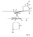
- FIG. 5 a a schematic diagram of a stretching experiment with a measurement probe on a measurement object in a starting state
- FIG. 5 b a schematic diagram of the stretching experiment with the measurement probe on the measurement object of FIG. 5 a in a stretched state, wherein a readjustment has taken place.
- FIG. 1 a shows a schematic diagram of a stretching experiment with a measurement probe 10 on a measurement object 1 in a starting state.
- FIG. 1 b shows a schematic diagram of the stretching experiment of FIG. 1 a with the measurement probe 10 on the measurement object 1 in a stretched state.
- the measurement object 1 to be observed is a subsection of a cell 2 which is fixed to a base 3 , also referred to as the support.
- the base is secured to a frame 20 which is shown schematically.
- the measurement object 1 may in a different embodiment be located between the cell 2 and the base 3 and establish a contact.
- the cell 2 is then brought into contact with another cell 12 which is fixed to a measurement probe 10 designed as a cantilever.
- the cantilever 10 is fixed for handling purposes to a component 11 , which is for example a silicon component and which in turn is connected via a piezo component 40 to a frame 20 . Between the component 11 and the piezo component 40 there are usually further components which are omitted here for the sake of clarity.
- a measurement objective 30 fixed to a further frame 20 a and an optical device not shown in greater detail here, for example a commercially available inverted microscope, an observation region designed as a focusing plane 31 is set in such a way that the measurement object 1 can be sharply imaged.
- the measurement objective 30 is part of an optical measurement system by means of which the measurement object 1 is optically examined.
- the piezo component 40 is shortened such that there is still contact between the two cells 2 , 12 , then a force acts on the cantilever 10 .
- the latter bends from the original position, shown in dashed line in FIG. 1 b , to a changed position 14 . Since both cells 2 , 12 change their shape, a shape-modified cell 5 and a further shape-modified cell 15 are produced.
- the travel brought about by the piezo component 40 is denoted by the distance between two auxiliary lines 18 , 19 . These are aligned with the base of the cantilever 10 .
- the measurement object 1 is coupled to the base 3 and thus to another frame 20 b , the position of the measurement object 1 does not change. Since the measurement objective 30 is connected to the further frame 20 a , the movement of the cantilever 10 has no effect on the imaging during the optical examination of the measurement object 1 by means of the measurement objective 30 .
- FIG. 2 a shows a schematic diagram of a stretching experiment with a measurement probe 10 on a measurement object 1 in a starting state.
- FIG. 2 b shows a schematic diagram of the stretching experiment of FIG. 2 a with the measurement probe 10 on the measurement object 1 in a stretched state.
- the starting situation in FIG. 2 a corresponds substantially to the situation in FIG. 1 a , apart from the fact that now the component 11 is fixed directly to the frame 20 and the base 3 is fixed to the other frame 20 b via another piezo component 40 b .
- the base 3 and the other piezo component 40 b have been omitted without limiting the general nature.
- the cantilever 10 and the cells 2 , 12 once again bend.
- the measurement object 1 is no longer located in the focusing plane 31 , but rather in a plane 32 and is accordingly imaged by the measurement objective 30 with a poorer optical quality.
- the quality of the imaging naturally depends greatly on the travel, which is once again denoted here by the two auxiliary lines 18 , 19 .
- FIG. 3 a shows a schematic diagram of a stretching experiment with a measurement probe 10 on a measurement object 1 in a starting state.
- FIG. 3 b shows a schematic diagram of the stretching experiment of FIG. 3 a with the measurement probe 10 on the measurement object 1 in a stretched state, wherein a readjustment has taken place.
- the starting situation in FIG. 3 a corresponds substantially to the situation in FIG. 2 a .
- the only difference is that now the measurement objective 30 for the optical measurement is attached to a vertical adjustment device 50 which can be moved via a control mechanism 51 .
- a sensor 52 is provided, by means of which the excursion of the other piezo component 40 b or preferably also of the cell 2 can be measured.
- FIG. 3 b shows a situation in which once again the other piezo component 40 b has been shortened.
- the excursion is measured and corresponding data signals are transmitted to the control mechanism 51 .
- the control mechanism 51 then triggers a movement of the measurement objective 30 via the adjustment device 50 , as a result of which a changed focusing plane 33 is produced, so that the measurement object 1 is once again located in the observation region of the measurement objective 30 . This ensures that the measurement object 1 is always in the focus of the measurement objective 30 .
- FIG. 4 a shows a schematic diagram of a stretching experiment with a measurement probe 10 on a measurement object 1 in a starting state.
- FIG. 4 b shows a schematic diagram of the stretching experiment of FIG. 4 a with the measurement probe 10 on the measurement object 1 in a stretched state, wherein a readjustment has taken place.
- FIG. 4 a shows the starting situation, which is very similar to the situation in FIG. 1 a .
- the differences lie in the position of the measurement object 1 and of the focusing plane 31 and also in the readjustment device including the adjustment device 50 , the control mechanism 51 , a sensor unit 152 as well as a laser 60 and a further sensor 61 , which is for example a 2 segment photodiode.
- the piezo component 40 is shortened, as a result of which a new position is obtained for the measurement object, 1 which makes the changed focusing plane 33 (observation region) necessary. Due to the bending of the cantilever 10 , however, the distance between the focusing plane 31 and the changed focusing plane 33 is not as great as the travel brought about by the piezo component 40 , namely the distance between the two auxiliary lines 18 , 19 . This is taken into account by providing, in addition to a data signal from the sensor unit 152 , also a data signal from the further sensor 61 and thus an indication of the bending of the cantilever 10 .
- the bending is measured by a light pointer in which, by means of the laser 60 , a laser measurement beam 65 is focused onto the cantilever 10 and a reflected beam 66 is received by the further sensor 61 and evaluated.
- a light pointer in which, by means of the laser 60 , a laser measurement beam 65 is focused onto the cantilever 10 and a reflected beam 66 is received by the further sensor 61 and evaluated.
- Such a manner of measuring the bending of the cantilever 10 is known per se to the person skilled in the art, and therefore there is no need for a more detailed description here.
- further methods for measuring the bending are known and can likewise be used, for example measuring a deflection by means of an interferometer.
- FIG. 5 a shows a schematic diagram of a stretching experiment with a measurement probe 10 on a measurement object 1 in a starting state.
- FIG. 5 b shows a schematic diagram of the stretching experiment of FIG. 5 a with the measurement probe 10 on the measurement object 1 in a stretched state, wherein a readjustment has taken place.
- the measurement object 1 is connected to the cell 2 in such a way that it moves as a result of the acting force or the expansion within the cell 2 or at least moves relative to the cantilever 10 and/or to the base 3 .
- FIG. 5 a once again shows the starting situation, which differs only by a few features from that shown in FIG. 4 a .
- the measurement object 1 is now arranged centrally in the cell 2 .
- the control mechanism 51 is connected to a model component 70 , for example an electronic memory, which contains information that can be evaluated electronically regarding a model of the vertical course of the measurement object 1 as a function of the acting force and the total excursion during the examination by means of scanning probe microscopy. From this information, the position of the measurement object 1 can be determined as a result of the measurement by means of scanning probe microscopy, so that the focus can be readjusted.
- the model component 70 and preferably also the control mechanism 51 are preferably implemented by a computer. Further parameters, for example the temperature or the pH of the cell 2 , may also be included; however, these are not shown here for the sake of clarity. Assistance may also be provided by an evaluation of the optical signal measured by the optical measurement system.
- FIG. 5 b shows the mode of operation.
- the measurement object 1 has moved upwards, and the changed focusing plane 33 has been set successfully, although at the start of the experiment the distance of the focusing plane 31 to the new position of the focusing plane 33 may differ greatly from the travel movement denoted by the two auxiliary lines 18 , 19 . This can also be achieved without involving an evaluation unit of the microscope.
- One advantage of the invention consists in that the optical measurement can be carried out at a very specific point in time, for example upon the breaking of a contact during the examination by means of scanning probe microscopy, and for the rest of the time a shutter prevents fluorescence molecules, for example, from bleaching out.
- the base 3 were to be moved instead of the cantilever 10 or if the measurement object 1 were to be bound to the upper cell 12 or even located between the two cells 2 , 12 , the situation would be similar, in other words a model would have to be used which, with the aid of the excursion and the cantilever bending and optionally further parameters, is able to pre-calculate a course of the measurement object 1 , namely the local position thereof, with suitable accuracy.
- the illustration of the two cells 2 , 12 on either side is merely an example of a configuration. Other possible arrangements may also be provided, such as for example one cell on the cantilever 10 and a homogeneous coated sample as the base.
- the displacement of the measurement object 1 brought about as a result of the examination by means of scanning probe microscopy can also be caused by a compression.
Abstract
Description
-
- The support for the sample is moved, for example by means of a piezo arrangement, in order to vary the distance between the sample and the measurement probe. If the object to be optically examined, in particular a subsection of the sample, is fixedly connected to the sample, this leads to defocusing.
- The measurement probe is moved by means of a piezo arrangement in order to vary the distance between the sample and the measurement probe. If the object to be optically examined is fixedly connected to the measurement probe, this leads to defocusing.
- If the measurement object is a part of the sample which is varied or displaced by the acting forces, defocusing will take place regardless of the moving part.
Claims (25)
Applications Claiming Priority (4)
| Application Number | Priority Date | Filing Date | Title |
|---|---|---|---|
| DE102005049562 | 2005-10-13 | ||
| DE102005049562 | 2005-10-13 | ||
| DE102005049562.1 | 2005-10-13 | ||
| PCT/DE2006/001131 WO2007041976A1 (en) | 2005-10-13 | 2006-06-30 | Method for examining a measurement object, and apparatus |
Publications (2)
| Publication Number | Publication Date |
|---|---|
| US20090205089A1 US20090205089A1 (en) | 2009-08-13 |
| US8769711B2 true US8769711B2 (en) | 2014-07-01 |
Family
ID=36972960
Family Applications (1)
| Application Number | Title | Priority Date | Filing Date |
|---|---|---|---|
| US12/083,303 Active 2028-03-24 US8769711B2 (en) | 2005-10-13 | 2006-06-30 | Method for examining a measurement object, and apparatus |
Country Status (5)
| Country | Link |
|---|---|
| US (1) | US8769711B2 (en) |
| EP (1) | EP1934578A1 (en) |
| JP (1) | JP2009511882A (en) |
| CN (1) | CN101326433A (en) |
| WO (1) | WO2007041976A1 (en) |
Families Citing this family (4)
| Publication number | Priority date | Publication date | Assignee | Title |
|---|---|---|---|---|
| US7977636B2 (en) * | 2008-08-12 | 2011-07-12 | Anasys Instruments, Inc. | Infrared imaging using thermal radiation from a scanning probe tip |
| JP2010198153A (en) * | 2009-02-24 | 2010-09-09 | Nec System Technologies Ltd | Redundant system, redundancy method, and program |
| JP5814855B2 (en) * | 2012-04-27 | 2015-11-17 | 株式会社日立ハイテクノロジーズ | Charged particle beam adjustment support apparatus and method |
| CN104946523B (en) * | 2015-05-28 | 2017-09-15 | 三捷生物科技(北京)有限公司 | The measurement apparatus and measuring method of a kind of cyto-mechanics |
Citations (6)
| Publication number | Priority date | Publication date | Assignee | Title |
|---|---|---|---|---|
| DE4233399A1 (en) | 1992-10-05 | 1994-04-07 | Zeiss Carl Fa | Force microscope with cantilevered point and deflection photodetector - is based on measurement of astigmatism in compact sensor head revolvable into path of optical microscope |
| JPH0755457A (en) | 1993-08-23 | 1995-03-03 | Hitachi Constr Mach Co Ltd | Method for positioning probe microscope device |
| US5952562A (en) * | 1995-11-22 | 1999-09-14 | Olympus Optical Co., Ltd. | Scanning probe microscope incorporating an optical microscope |
| US20010030286A1 (en) * | 2000-03-28 | 2001-10-18 | Akira Egawa | Scanning probe microscope |
| US20020104963A1 (en) * | 1998-09-26 | 2002-08-08 | Vladimir Mancevski | Multidimensional sensing system for atomic force microscopy |
| US6452161B1 (en) | 2000-03-28 | 2002-09-17 | Advanced Micro Devices, Inc. | Scanning probe microscope having optical fiber spaced from point of hp |
-
2006
- 2006-06-30 JP JP2008534858A patent/JP2009511882A/en active Pending
- 2006-06-30 US US12/083,303 patent/US8769711B2/en active Active
- 2006-06-30 EP EP06761735A patent/EP1934578A1/en not_active Withdrawn
- 2006-06-30 WO PCT/DE2006/001131 patent/WO2007041976A1/en active Application Filing
- 2006-06-30 CN CNA2006800463238A patent/CN101326433A/en active Pending
Patent Citations (6)
| Publication number | Priority date | Publication date | Assignee | Title |
|---|---|---|---|---|
| DE4233399A1 (en) | 1992-10-05 | 1994-04-07 | Zeiss Carl Fa | Force microscope with cantilevered point and deflection photodetector - is based on measurement of astigmatism in compact sensor head revolvable into path of optical microscope |
| JPH0755457A (en) | 1993-08-23 | 1995-03-03 | Hitachi Constr Mach Co Ltd | Method for positioning probe microscope device |
| US5952562A (en) * | 1995-11-22 | 1999-09-14 | Olympus Optical Co., Ltd. | Scanning probe microscope incorporating an optical microscope |
| US20020104963A1 (en) * | 1998-09-26 | 2002-08-08 | Vladimir Mancevski | Multidimensional sensing system for atomic force microscopy |
| US20010030286A1 (en) * | 2000-03-28 | 2001-10-18 | Akira Egawa | Scanning probe microscope |
| US6452161B1 (en) | 2000-03-28 | 2002-09-17 | Advanced Micro Devices, Inc. | Scanning probe microscope having optical fiber spaced from point of hp |
Non-Patent Citations (2)
| Title |
|---|
| Optically Transparent Tip for Tunneling Microscopy, IBM Technical Disclosure Bulletin, Oct. 1987, p. 369-370, vol. 30, No. 5. |
| T. Fujii et al., Development of a new force microscope with a fluorescence optical microscope, Thin Solid Films, 1994, p. 407-410, vol. 243, Elsevier Sequoia. |
Also Published As
| Publication number | Publication date |
|---|---|
| WO2007041976A1 (en) | 2007-04-19 |
| EP1934578A1 (en) | 2008-06-25 |
| CN101326433A (en) | 2008-12-17 |
| JP2009511882A (en) | 2009-03-19 |
| US20090205089A1 (en) | 2009-08-13 |
Similar Documents
| Publication | Publication Date | Title |
|---|---|---|
| JP5580296B2 (en) | Probe detection system | |
| US6998602B2 (en) | Method of and an apparatus for measuring a specimen by means of a scanning probe microscope | |
| US7319528B2 (en) | Surface texture measuring instrument | |
| Yong et al. | Design of an inertially counterbalanced Z-nanopositioner for high-speed atomic force microscopy | |
| WO2010065131A2 (en) | High frequenct deflection measurement of ir absorption | |
| US5838000A (en) | Method device and system for optical near-field scanning microscopy of test specimens in liquids | |
| US8769711B2 (en) | Method for examining a measurement object, and apparatus | |
| US7581438B2 (en) | Surface texture measuring probe and microscope utilizing the same | |
| JP6135820B2 (en) | Scanning probe microscope | |
| JP4563117B2 (en) | Microscope system, microscope system scanning method, and microscope system image composition method | |
| US8381311B2 (en) | Method for examining a test sample using a scanning probe microscope, measurement system and a measuring probe system | |
| US8477319B2 (en) | Measuring apparatus | |
| KR101173607B1 (en) | Bio sensor apparatus having real-time ditection about physical change of bio matter and method of sensing | |
| JP2008051690A (en) | Optical displacement detecting mechanism, and surface information measuring device using the same | |
| WO2005098869A1 (en) | Scanning probe microscope with integrated calibration | |
| JP5226837B2 (en) | Spot light alignment method of optical displacement detection mechanism for scanning probe microscope | |
| KR101025657B1 (en) | Atomic force microscope and method for correcting scan image thereof | |
| RU2510009C1 (en) | Device to measure parameters of surface relief and mechanical properties of materials | |
| US20070012095A1 (en) | Scanning probe microscope | |
| JP3713695B2 (en) | Scanning probe microscope | |
| KR101243213B1 (en) | Optical fiber imaging apparatus using optical interference, tracking apparatus for sample position based on image, optical fiber imaging method using optical interference, tracking method for sample position based on image and recording medium thereof | |
| TWI285273B (en) | Beam tracking system for scanning-probe type atomic force microscope | |
| JPH07174767A (en) | Scanning type probe microscope | |
| JPH08285865A (en) | Scanning probe microscope | |
| Park et al. | Design of a compact atomic force microscope to enhance scanning speed |
Legal Events
| Date | Code | Title | Description |
|---|---|---|---|
| AS | Assignment |
Owner name: JPK INSTRUMENTS AG, GERMANY Free format text: ASSIGNMENT OF ASSIGNORS INTEREST;ASSIGNOR:JAEHNKE, TORSTEN;REEL/FRAME:032369/0904 Effective date: 20090311 |
|
| STCF | Information on status: patent grant |
Free format text: PATENTED CASE |
|
| FEPP | Fee payment procedure |
Free format text: MAINTENANCE FEE REMINDER MAILED (ORIGINAL EVENT CODE: REM.) |
|
| FEPP | Fee payment procedure |
Free format text: SURCHARGE FOR LATE PAYMENT, SMALL ENTITY (ORIGINAL EVENT CODE: M2554) |
|
| MAFP | Maintenance fee payment |
Free format text: PAYMENT OF MAINTENANCE FEE, 4TH YR, SMALL ENTITY (ORIGINAL EVENT CODE: M2551) Year of fee payment: 4 |
|
| FEPP | Fee payment procedure |
Free format text: ENTITY STATUS SET TO UNDISCOUNTED (ORIGINAL EVENT CODE: BIG.); ENTITY STATUS OF PATENT OWNER: LARGE ENTITY |
|
| MAFP | Maintenance fee payment |
Free format text: PAYMENT OF MAINTENANCE FEE, 8TH YEAR, LARGE ENTITY (ORIGINAL EVENT CODE: M1552); ENTITY STATUS OF PATENT OWNER: LARGE ENTITY Year of fee payment: 8 |
|
| AS | Assignment |
Owner name: BRUKER NANO GMBH, GERMANY Free format text: MERGER;ASSIGNOR:JPK INSTRUMENTS AG;REEL/FRAME:064191/0863 Effective date: 20180904 Owner name: JPK INSTRUMENTS AG, GERMANY Free format text: CHANGE OF ADDRESS;ASSIGNOR:JPK INSTRUMENTS AG;REEL/FRAME:064205/0902 Effective date: 20180904 |