US8760391B2 - Input cueing emersion system and method - Google Patents
Input cueing emersion system and method Download PDFInfo
- Publication number
- US8760391B2 US8760391B2 US12/786,324 US78632410A US8760391B2 US 8760391 B2 US8760391 B2 US 8760391B2 US 78632410 A US78632410 A US 78632410A US 8760391 B2 US8760391 B2 US 8760391B2
- Authority
- US
- United States
- Prior art keywords
- image
- input
- display
- user
- input area
- Prior art date
- Legal status (The legal status is an assumption and is not a legal conclusion. Google has not performed a legal analysis and makes no representation as to the accuracy of the status listed.)
- Active - Reinstated, expires
Links
Images


Classifications
-
- G—PHYSICS
- G06—COMPUTING; CALCULATING OR COUNTING
- G06F—ELECTRIC DIGITAL DATA PROCESSING
- G06F3/00—Input arrangements for transferring data to be processed into a form capable of being handled by the computer; Output arrangements for transferring data from processing unit to output unit, e.g. interface arrangements
- G06F3/01—Input arrangements or combined input and output arrangements for interaction between user and computer
- G06F3/011—Arrangements for interaction with the human body, e.g. for user immersion in virtual reality
-
- G—PHYSICS
- G06—COMPUTING; CALCULATING OR COUNTING
- G06F—ELECTRIC DIGITAL DATA PROCESSING
- G06F3/00—Input arrangements for transferring data to be processed into a form capable of being handled by the computer; Output arrangements for transferring data from processing unit to output unit, e.g. interface arrangements
- G06F3/01—Input arrangements or combined input and output arrangements for interaction between user and computer
- G06F3/017—Gesture based interaction, e.g. based on a set of recognized hand gestures
Definitions
- the present invention is related to drawing tables and text entering devices, and more particularly to such tables and devices coupled to a computer or data processing device that enables the drawing and/or text to be transmitted and viewed in combination with the input action on the computer's display monitor.
- Portable devices such as a laptop computer, Slate, Tablet, PDA, or a multiple function cellular telephone are very popular. Because such devices have small keyboards, most user's employ a single finger or thumb on each hand and input letters and numbers via a ‘hunt and peck’ method. The ‘hunt and peck’ method normally requires that the user look at the keys on the keyboard.
- Various embodiments of the present invention provide a hand cueing input system and method that enables input from the user's hand(s), finger(s), tool(s) or other inputting means to an information processing system such as a computer, to be transmitted and viewed immediately on an output display of the computer such as but not limited to a computer display monitor or visual display unit referred to as a display, with the input being matched and or combined with the output of the computer to enable a real time, intuitive and meaningful cueing to the user from the display for a more process efficient, time improved, more ergonomically correct and overall more enjoyable experience on the computer.
- an input cueing emmersion device is used in combination or not with a computer and output display that allows an operator to input and capture drawings, text, gestures, point clicking and other interaction activities (similar to the functions of a normal touch screen).
- Visual images of pictures, drawings, text, or other graphic media can be easily inputted, viewed and or changed, and stored into an information processing system such as a computer, and/or the input cueing emmersion device itself.
- a hand input system e.g., for portable devices, that enables users to view a their hand(s), finger(s) tool(s) or other inputting means, active or passive, either on the device itself or in combination with a computer to simultaneously watch the relative positions of the their hand(s), finger(s) tool(s) or other inputting means (hereinafter, “hands”) on an input surface while the image is created on the display.
- hands e.g., for portable devices, that enables users to view a their hand(s), finger(s) tool(s) or other inputting means, active or passive, either on the device itself or in combination with a computer to simultaneously watch the relative positions of the their hand(s), finger(s) tool(s) or other inputting means (hereinafter, “hands”) on an input surface while the image is created on the display.
- Additional embodiments provide a hand cueing input system for a computer (or any type of data processing device, machine, etc.) that enables a user to manually or automatically input data onto an input surface coupled to the computer and allows the user to simultaneously observe the position of his hands (and/or fingers, writing implement, drawing implement, or other objects/tools on/in/about/above the input and/or surface) combined with an image created on a display by an operating system (and/or turnkey firmware, drawing software program, text word processing field, spreadsheet, database, Web browser etc.) loaded into the working memory of the computer.
- an operating system and/or turnkey firmware, drawing software program, text word processing field, spreadsheet, database, Web browser etc.
- Additional embodiments provide a hand cueing input system for a computer (or any type of data processing device, machine, etc.) that enables a user to manually or automatically input data onto an input surface interacting with but not limited to visual imagery graphics virtual keyboards or keying schema or in combination or not with other physical objects, such as but not limited to, styluses or other pen-shaped instruments, keyboards, texting devices and writing devices coupled physically and/or visually to the computer and allows the user to simultaneously observe the position of his hands on/in/about/above the input and/or surface and/or other physical objects, combined with an image created for the display by a the computer.
- This may be virtual representations from physical objects, or the combination of booth being aligned and/or matched up or not, such as but not limited to, physical styluses, styluses or other pen-shaped instruments, keyboards, texting devices and writing devices
- “Point-and-click” is a 2-action process where a computer user moves a cursor using a physical object held under one of the user's hands, with one or more buttons, to a target location on a screen (point) and then after arriving at the target, presses a button, (click) which then completes the action.
- Point-in-clicking is a faster, more accurate, more precise, more sub-conscious (less cognitive taxing), more of a straight angle “one vector” movement, to the desired target.
- Press-and-click is a “2-vector” movement that requires first, finding and moving a disembodied pointer in the first vector, on the x/y plane (hands moving horizontally) to a desired target, usually a small discrete region, commonly overshooting the target one or more times, checking and then correcting if necessary until the desired area is satisfactorily reached. Only when this is accomplished, the second vector movement on the z-axis (a button pressing usually in the vertically down direction) is performed.
- MMT is the average mean movement time taken to complete the movement
- a is the start/stop time of the device
- A is the distance from the starting point to the center of the target
- W is the width of the target measured along the axis of motion.
- a system that enables the user to adjust of the viewable area on the input surface that is shown on the display or non-visual output mechanism.
- the displays set forth herein may be foldable, collapsible and/or portable.
- Some embodiments of the invention provide a system that enables an artist's hands to be shown in a semi-transparent or opaque, transposed manner over the image generated by a drawing tablet and shown on a display so that the total image shown on the display simulates the ‘look and feel’ of the artist looking at their hands while drawing on a piece of paper on a table.
- the embodiments of the invention are not based upon keyboard mapping (several keys are “mapped” to represent one particular key so as to allow for misalignment).
- the pixels or display elements are matched very closely with the input X, Y and/or Z input coordinates. This matching or calibration of the display elements to the input X, Y and/or Z input coordinates is maintained through normal use and does not drift noticeably to a user as to be an unpractical annoyance.
- physical indexes, detents, wells or markers are provided either outside of but not limited to the frame our outer type of border not necessarily associated with the actual input area or not, in order to guide, align or otherwise detect the user's hand, palm, finger or tool to a start or “home position” to facilitate a more accurate locating of the keys of a virtual or physical keyboard, virtual or physical button, input icons, drawings, numbers, text and or data manipulation fields or “variable input operators.”
- a physical keyboard and a virtual keyboard are provided having matching coordinates so as to be allowed to activate and show the activated key on the screen while the physical finger (and/or tool upon covering the key) is still shown on a display to allow visual cueing that the correct key was pressed, while allowing the tactile feel and nature of striking a physical key.
- a physical keyboard could be supplied with the device or added on later, so that there could already be a “correctness” or calibration quality inherently built-in due to the physical aligning opening up or otherwise operating position of the keyboard to facilitate the quickness of the start time operation of the keyboard.
- Another keyboard that may not be already supplied or otherwise “built-in” could be provided through firmware and/or software in the device itself, in combination or not with firmware and or software in the working memory of the computer. This additional keyboard would not necessarily have to be aligned to any particular coordinates. The firmware and or software in the device itself would find and perform this alignment “correctness” and or calibration quality whether automatic or not as in initiated by the user.
- these physical bump(s), indent(s), well(s) or otherwise changed condition(s) of the “normal” smoother surface model being temporary, they can be made to change back to the “normal” smoother surface model that would not exhibit these physical bump(s) indent(s), well(s) and/or otherwise changed condition(s) of the “normal” smoother surface.
- the surface could be more “flat” and aberration free to be more conducive to drawing by virtue of none of these bump(s), indent(s), well(s) or otherwise physical mars, aberrations or changes to the physical surface to slow, stop, impair and/or reduce or guide incorrectly the intend motion of the hands.
- the bumps may be permanently fixed.
- image type filtering including, but not limited to, chroma key type effects and or analog/digital voltage pass filtering, for various visual purposes including but not limited to educational, artistic and/or entertainment purposes, and/or for improved clarity of image input of hands fingers, tools and or objects due to control over physical input base characteristics.
- Additional embodiments provide the ability to have different views of the user area such as, but not limited to, the complete table/desk surface, the input area only, smaller portions of the input area and magnified areas or even a microscope combination or arrangement.
- Various embodiments provide the ability to have physical buttons, whether temporary or not, but able to be lined up in combination with a virtual of the button.
- Yet further embodiments provide the ability to have physical shape differentiation such as, but not limited to, concave or convex attributes to distinguish between different characters, symbols state changing inputs and or text input.
- Such objects may be shaped as one large button so that all of theses shape differentiation keys would have no obvious crevices, spaces, or other non-seamless type featuring as to allow for easy cleaning and for easy sanitizing, sterilizing and general hygienic use.
- the ability to have 3D type qualities may also be provided.
- an “imaging” may include image transfer or relay mechanisms such as, but not limited to, prisms, fiber optics, CCDs (charge coupled devices), CMOSs (complementary metal oxide semiconductors), mirrors, reflectors, whether in any curved manner or other optical type or “imaging” or image capturing and/or carrier mechanisms and/or transmission systems.
- imaging systems may be electronic in nature or not, and may be adapted to process images using the visible spectrum, ultra violet, infrared, near infrared, far radio waves, x-rays, gamma rays, or other physical transmission such as audio waves, and/or sonar waves.
- Further embodiments provide the ability to have different views of user area such the complete table/desk surface, the input area only, smaller portions of the input area and magnified areas or even a microscope combination or arrangement.
- imaging systems provide a reduced or more practical configuration and/or aid in a shortening or reduced overall height, length and/or otherwise smaller overall form of the device, removed twice by the imaging systems.
- Other embodiments may be removed three times, four times, and so on increasing the number of times removed by the “imaging” and or carrier mechanisms and or transmission systems.
- Some embodiments may feature deforming materials such as, but not limited to, urethane, non-vulcanized natural rubbers, synthetic rubbers, copolymers, semi-transparent, transparent or opaque, or more “hard style” designs such as a guided solid as in, but not limited to, piston styles and or hinging configurations, etc.
- Physical energy to drive changes in the surface can be supplied by hydraulics, pneumatics, solid force, electromechanics and/or being of a solid state nature. Heat, sound, vibration and/or snap feel or other sensing stimuli as well can be used in conjunction with and coordinated visually on the display(s) by some noticeable visual indication whether graphically localized to the action area or more generally on the entire screen or any combination in between can be orchestrated.
- Some embodiments may be used for controlling and/or operating and/or viewing indicators, buttons, or any input and/or outputs etc., of any type of vehicle whether on land sea air or space. Another application involves controlling and/or operating any kind of machinery.
- Input technologies and/or other input mechanisms such as resistive, surface acoustic wave, capacitive, surface capacitance, projected capacitance, mutual capacitance, self capacitance, strain gauge, optical imaging, dispersive signal technology, acoustic pulse recognition, and/or Coded LCD in combination or not with a computer and/or the input cueing emmersion system itself, having software, firmware and/or operating system software or otherwise program etc., to understand and/or recognize and interact with either the drawing, pieces of the drawing, etc., and/or gestures by the user's hands.
- input cueing emmersion system itself, having software, firmware and/or operating system software or otherwise program etc.
- different surfaces could be allowed to come either as the original unit or be inserted or attached to provide a modular type of changeability at a later time.
- the different surfaces allow for different types of “feel,” “resistance,” or otherwise interaction for a interesting, pleasing or otherwise more preferred type of “feel” for drawing, sketching and/or other point clicking activities and/or interaction
- FIG. 1 is a perspective view of a hand cueing input system used with a desktop computer and monitor.
- FIG. 2 is a side elevational view of the hand cueing input system shown in FIG. 1 .
- FIG. 3 is a block diagram showing the components used in the hand cueing input system showing in FIGS. 1 and 2 .
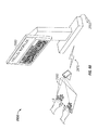
- FIG. 4 is a top plan view of a tablet mobile computing device 45 being placed on platform 40 .
- FIG. 5 is a side elevational view of the multiple camera hand cueing input system similar to the system shown in FIGS. 1-4 .
- FIG. 6 is an illustration showing the image created by a video camera and primary mirror that shows an entire modified drawing tablet with a front drawing surface and a movement detection area.
- FIG. 7 is an illustration similar to the illustration shown in FIG. 6 showing the image created by another set of video camera and a primary mirror that shows outer areas of the drawing tablet.
- FIG. 8 is an illustration similar to the illustration shown in FIGS. 6 and 7 showing the image by another set of video camera and a primary mirror that shows the drawing surface and the movement detection area.
- FIG. 9 is an illustration similar to the illustration shown in FIGS. 7-8 showing the image by another set of video camera and primary mirror that shows a small section of the drawing surface.
- FIG. 10 illustrates a “finger painting” view size showing a small captured input area
- FIG. 11 is a perspective view of a second embodiment of the hand viewing input system shown incorporated into a laptop computer.
- FIG. 12 is a side elevational view of the laptop computer with the hand viewing input system incorporated therein in a closed position.
- FIG. 13 illustrates a side view of the laptop computer in its closed position.
- FIG. 14 is a perspective view of a third embodiment of the hand viewing input system shown incorporated into a handheld PDA or cellular telephone.
- FIG. 15 is a side elevational view of a laptop computer with two mirrors and a single camera.
- FIG. 16 is a block diagram of a controller.
- FIG. 17 is a side elevational view of a laptop computer with a single mirror mounted on the distal end of the strut with a single camera.
- FIG. 18 is a side elevational view of a handheld device with a single mirror mounted on the distal end of the strut with a single camera.
- FIG. 19 is an illustration of an X, Y and/or Z input showing the area that is shown on the display.
- FIG. 20 is an illustration of an X, Y and/or Z input and display showing a section of the X, Y and/or Z input being activated and exploded onto the display.
- FIG. 21 is a perspective view of a folded input cueing emmersion device.
- FIG. 22 is a perspective view of an opened input cueing emmersion device opened with a hand drawing.
- FIG. 23 is a perspective view of an opened input cueing emmersion device with a virtual keyboard being shown on the built-in display.
- FIG. 24 is a perspective view of a physical keyboard on top of the input cueing emmersion device input aligned in a perpendicular fashion to the operator.
- FIG. 25 is a side angle of a small form factor input cueing emmersion device (with computer and finger).
- FIG. 26 is a rear view illustrating folding model concepts.
- FIG. 27 illustrates a physical keyboard on top of an input cueing emmersion device, wherein the physical keyboard is not aligned in a perpendicular fashion to the operator.
- FIG. 28 illustrates a separate keyboard that is detached from the front of the input cueing emmersion device.
- FIG. 29 illustrates a separate keyboard that is physically attached to the front of the input cueing emmersion device.
- FIG. 30 illustrates an anytime teller machine (“ATM”) with an image capturing or image carrier mechanism below the display.
- ATM anytime teller machine
- FIG. 31 illustrates an ATM with an image capturing or image carrier mechanism above the display.
- FIG. 32 illustrates a Swedish keyboard with semi-transparent hands.
- FIG. 33 illustrates a Japanese keyboard with semi-transparent hands.
- FIG. 34 illustrates a French keyboard with semi-transparent hands.
- FIG. 35 is a side view illustrating the commonly accepted angles for peripheral vision.
- FIG. 36 is a side view illustrating the commonly accepted ergonomic set up for a computer user at a workstation.
- FIG. 37 illustrates an input cueing emmersion device having a keyboard with detents.
- FIG. 38 is a top view illustrating the commonly accepted ergonomic arm reach and movement fields for a person sitting down and performing tasks on a desktop.
- FIG. 39 is another top view illustrating the commonly accepted ergonomic arm reach and movement fields for a person sitting down and performing tasks on a desktop.
- FIG. 40 is a perspective view of an input cueing emmersion device while a hand drawing is being created while observing the action on an external display.
- FIG. 41 illustrates an input cueing emmersion device with a unitized keyboard and input area.
- FIG. 42 illustrates an input cueing emmersion device having a dotted line from the input area to where it would be seen on a display.
- FIG. 43 illustrates another input cueing emmersion device having a dotted line from the input area to where it would be seen on a display.
- FIG. 44 is a side view of an input cueing emmersion device showing various opening and closing aspects of a display.
- FIG. 45 is another side view of an input cueing emmersion device showing various opening and closing aspects of a display.
- FIG. 46 is a perspective view of an input cueing emmersion device in an opened configuration with hands typing.
- FIG. 47 is a perspective view of an input cueing emmersion device, wherein the computer operator's right hand is typing and the left hand is pressing a virtual button.
- FIG. 48 is a perspective view of an input cueing emmersion device, wherein the computer operator's left and right hands are manipulating a virtual image.
- FIG. 49 is a perspective view of an input cueing emmersion device, wherein the computer operator's right hand is typing and the left hand is drawing.
- FIG. 50 is a perspective view of an input cueing emmersion device, wherein the computer operator's right hand is typing and the left hand is drawing.
- FIG. 51 is a perspective view of an input cueing emmersion device, wherein the computer operator's right hand is typing and the left hand is drawing.
- FIG. 52 illustrates a display and an area designated for a small input device such as a finger 2520 .
- FIG. 53 illustrates an input cueing emmersion device and a computer operator's hands typing.
- FIG. 54 is a block diagram showing the components used in the hand cueing input system showing in FIGS. 1 and 2 .
- FIG. 55 is a side view illustrating a hand held input cueing emmersion device having two image transfer devices and one image capturing device.
- FIG. 56 is a side view illustrating hand held input cueing emersion device 2700 being held in a hand 8 and being operated with a finger 2740 .
- FIG. 57 is a perspective view illustrating hand help input cueing emersion device 2700 having a ‘calm shell’ form factor and being operated with finger 2740 .
- FIG. 58 is a side view illustrating a standalone hand held input cueing emmersion device that operates by itself and includes an internal display.
- FIG. 59 is a side view illustrating a laptop hand held input cueing emmersion device having only one image capturing device with no image transfer device.
- FIG. 60 illustrates a small pocket sized PDA, Smartphone and/or computer having a laser or LED.
- FIG. 61 illustrates a small pocket sized PDA, Smartphone and/or computer having a laser or LED with computer video output projected in space to a vertical planar surface.
- FIG. 62 illustrates a small pocket sized PDA, Smartphone and/or computer having a laser or LED, and a connectable temporary cable to a hard wired permanent signal cable display output.
- FIG. 63 illustrates an embodiment using only one image capturing device with no image transfer device.
- FIG. 64 is a diagram illustrating an example computing module for implementing various embodiments of the invention.
- the present invention is directed toward a hand cueing input system and method that enables drawings and/or text to be transmitted and viewed immediately on a computer display monitor.
- a simple, drawing system is provided that allows a drawing hobbyist to produce drawings that can be easily inputted, viewed and or changed and if necessary, stored into a computer.
- the hand cueing input system disclosed herein allows a user to simultaneously watch his hand or hands and/or fingers, writing implement, drawing implement, or other objects/tools (hereinafter, “hands”) on/in/about/above an X, Y and/or Z input and/or input surface combined with an image created on a display by an operating system (and/or turnkey firmware, drawing software program, text word processing field, spreadsheet, database, Web browser etc.) loaded into the working memory of the computer (or CPU, microprocessor, field programmable gate array, other type of processor, or other type of data processing device) or machine (e.g., laptop, Slate, Tablet, Palm top, PDA, etc.) coupled to the input surface (hereinafter, “computer”).
- an operating system and/or turnkey firmware, drawing software program, text word processing field, spreadsheet, database, Web browser etc.
- machine e.g., laptop, Slate, Tablet, Palm top, PDA, etc.
- the input surface may comprise a digitalized drawing tablet, touch pad, or X, Y and/or Z surface detection device of any variety (e.g., capacitive, infrared, ultra violet light, visible light, strain gauge etc., multi touch, etc.).
- the input is coupled to a computer or any other type of data processing device or machine etc., with a drawing program loaded into its working memory.
- a drawing is created on the input that (via the software program) immediately produces a drawing shown on a display.
- Located above the input surface is at least one video camera (or image capturing device of any technology) that captures a live video image of the user's hands and other objects or tools positioned in the field of view on the input surface.
- a primary mirror and a secondary mirror or other video or optical transferring means are located between the input surface and the video camera to effectively reduce the height or focal length so that the video image is properly aligned and oriented. This proper orientation and alignment provides a real ‘live’ distance with either a non-perspective direct overview, or a perspective view of the drawing on the display as it is being generated.
- the X, Y and/or Z input is a structure designed to connect to a separate display and a separate computer with a CPU or microprocessor (or any other type of data processing device or machine having a working memory.
- the input is configured as a stand alone portable device, embodied within or replacing a laptop computer.
- the portable device may comprise a Slate, Tablet, or smaller Palm top or PDA, and includes its own CPU, CPU component, microprocessor, field programmable gate array or any other type of processor or processors.
- the portable device may include a working memory and/or any other type of data processing device, machine, etc., as well as a built-in display or displays and/or non-visual output mechanism (hereinafter, “display”).
- This portable embodiment could fold and/or close in any manner or contrivance to become smaller, more portable, and/or easier to hold, so the overall “carrying footprint” would be reduced.
- an operating system, turnkey firmware, drawing software program, text word processing field, spreadsheet, database, Web browser and/or video capture/display program are loaded into the working memory of the computer
- the system includes a combiner module designed to combine the outputs from the external computer and the video camera or image capturing device, and simultaneously transmit them in a semi-transparent or opaque, combined, overlaying manner on the display.
- the combiner module may be built-into the X, Y and/or Z input, the image capturing device or the graphics. Alternatively, the combiner module may comprise a hardware component connected to a standalone computer.
- the system also includes a simple or complex controller that enables the X, Y and/or Z input to communicate with the computer. In one embodiment, the controller receives a digital or analog signal from the computer and then converts and or synchronizes it into a compatible signal to be used by the display.
- the controller is designed also to receive a synchronized signal from the combiner and transmit it to the computer for storage.
- the system includes the necessary drivers, operating system, turnkey firmware, drawing software program, text word processing field, spreadsheet, database, Web browser etc., loaded into the working memory of the external computer.
- input is input and output is output.
- the user's hands transfer data to an input device and the monitor provides the output to the user's eyes, which technically should only be looking at the monitor output and should not look away from the monitor to locate the mouse or keyboard.
- the mere act of looking at the mouse or keyboard has the effect of turning those input devices into outputs for the user's eyes.
- the user's hands should also be able to provide input intuitively being seen in the output, but without covering any part of the monitor and without having to hold one's hands up uncomfortably in the air to touch a touch screen.
- the user's hands rest comfortably on the desktop (rather than being held up in the air to touch a vertical Touchscreen monitor), and the user's eyes look forward, not angled down to look at the tabletop (which may cause neck injuries).
- This combination is more ergonomically comfortable and is not present on any currently available touch surface.
- the systems described herein are also very mobile, require no physical buttons, do not require a mouse, and do not result in visual parallax.
- normal touch screens have a glass or transparent media portion that is touched physically at least fractions of an inch “above” the “actual” display elements. This does not allow one to sense exactly the position of a finger or stylus.
- the various embodiments of the invention do not require a physical keyboard. Instead, a virtual keyboard can be popped up having varying degrees of transparency and which can be located on the “perch” portion of the device, instead of the monitor. A visual indication of the key may be selected by the user's fingertip, thus providing a better cue than a key that is pressed using a tactile type feedback.
- Various embodiments of the invention may also provide, (i) “Always Available” “Instant” STICKY NOTES, (ii) a quick photo copier, (iii) fax replacement, whereby documents may be signed that are being displayed on the screen, (iv) accurate robotic surgery control, (v) an improved handwriting input device, (vi) accurate missile control, (vii) accurate aircraft control, and (viii) a cost effective clean room computer interface device.
- the monitor stays clean because it is not generally touched by users at all in any normal usage.
- the system does not provoke a perspective induced viewing of the work. By contrast, looking down at a horizontal surface forces an unwanted perspective into drawings and the viewed artwork.
- the systems and methods set forth herein may be employed in surgery rooms, dental offices, electronics manufacturing, and many other industries.
- the systems and methods of the invention are very intuitive, like having one's hands “in the computer,” and further provide a feeling of “finger painting” in the computer.
- the systems may also be very mobile, provide the ability to left click and right click, provide the ability to have multiple pointing inputs, and provide the ability to put objects on the table that can also interact with the computer (e.g., electronic data-transfer as well as being visually displayed or represented).
- the XY touch input gives extremely accurate response and is inexpensive because it is not handicapped by needing a clear “view through” ability of a medium or technology.
- the hands input image is real time, and does not suffer from the latency of a web camera or computer processed video input.
- Different embodiments may include, but are not limited to: (i) a complete PC system; (ii) a complete laptop system; (iii) an input device specifically as a standalone laptop/desktop with a monitor on the perch/palmtop; and (iv) a small PDA clamshell form factor.
- FIGS. 1-20 there is shown an input cueing input system generally denoted by the reference number 10 connected to a desktop computer 12 and external display 70 .
- the system 10 allows the user to manually draw an image 72 on a drawing surface interface 28 of a digital drawing tablet 25 located directly in front of the user 8 which is then simultaneously displayed image 72 on the computer's display 70 .
- the computer 12 includes a working memory 14 , a video card 10 with a serial input port 18 (i.e. USB), and an output port 20 (VGA or DVI), and a display 70 connected to the video card's output port 20 .
- the serial input port 18 is compatible and capable of being connected to a video camera's cable 62 .
- the drawing tablet 25 includes a cable 28 88 designed to connected to the serial input port 18 .
- the drawing tablet 25 includes a flat drawing surface interface 28 that transmits the X, Y and or Z coordinate movements of the user's hand 8 or a suitable drawing implement 9 .
- the drawing software program 30 is designed to process the signals from the drawing surface interface 28 and convert them into a drawing image 72 visible on the display 70 .
- the drawing tablet 24 25 may be a graphic tablet, graphic pad, digitalizing tablet, or a computer input device that allows one to hand-draw images and graphics.
- drawing tablets 25 There are two main types of drawing tablets 25 .
- the first type is known as a ‘passive’ drawing tablet that uses the pressure generated on the flat surface or a drawing implement when drawing to open and close switches located on the flat surface or the drawing implement. The switches create electromagnetic signals that are transmitted to the drawing software program.
- the second type of drawing tablet is referred to as an ‘active tablet’ that uses a specialized drawing implement that contains electronics that generates, transmits and receives signals to and from the tablet. In the invention disclosed herein, both passive and active drawing tablets may be used.
- the drawing tablet 25 includes a digital drawing surface interface 28 mounted inside a rigid drawing table frame 32 .
- a strut 35 Mounted on the back edge of the drawing tablet 25 is a strut 35 .
- Mounted on the end of the strut 35 is a small platform 40 .
- Placed on or built into the top surface 44 of the platform 40 is an optional tablet mobile computing device 45 , and optional holders 46 for storing a stylus 15 used on the drawing surface interface 28 .
- FIG. 1 is a perspective view of an input cueing emmersion device with hands on the input of the input cueing emmersion device being viewed in a semi-transparent manner on a computer display.
- FIG. 2 is a side view of an input cueing emmersion device in the “opened up” mode showing a “see through” view of the separate components.
- the strut 35 is adjustably mounted on the back edge of the drawing tablet 35 . As shown in FIGS. 1 and 2 , the strut 35 extends diagonally upward and rearward from the drawing table frame 32 .
- the strut 35 is adjustably mounted on the table frame 32 by a first hinge 37 .
- the first hinge 37 includes a locking mechanism 39 that enables the strut 35 to be adjustably positioned over the drawing surface interface 28 and then locked into a fixed position.
- FIG. 3 is a system schematic illustrating, among other things, (i) the transmission line of video signal out of computer to the input cueing emmersion device, (ii) the transmission line of input signal to the computer, and (iii) the transmission line of combined video signal to the display or monitor.
- (i) and (ii) may be combined to be one cable (i.e., USB).
- all three transmission lines may be could be wireless.
- the primary mirror assembly 41 mounted on the bottom surface of the platform 40 is a primary mirror assembly 41 designed to receive and reflect the image of the hands and drawing stylus on the drawing surface interface 28 .
- the primary mirror assembly 41 includes a primary mirror 42 mounted inside an outer mirror frame. 44 .
- the outer mirror frame 44 is adjustably mounted on the distal end of the strut 35 so that the angle of the primary mirror assembly 40 may be selectively adjusted on the strut 35 by the user.
- a second hinge 46 is disposed between the strut 35 and the outer mirror frame 44 .
- the primary mirror 42 is a flat mirror that is aimed diagonally downward towards the drawing surface interface 28 .
- the primary mirror 42 has substantially the same overall shape as the drawing surface interface 28 only approximately 1 ⁇ 3 the size.
- the strut 35 is approximately 12 inches in length and the primary mirror 42 is located approximately 8 inches above the drawing surface. The strut 35 is disposed at an angel between 60 to 85 degrees from the normal, vertical axis.
- the secondary mirror assembly 50 mounted on the strut 35 below the platform and below the primary mirror assembly 40 is a secondary mirror assembly 50 designed to receive the reflected image of the drawing surface interface 28 from the primary mirror 42 .
- the secondary mirror assembly 50 includes a flat secondary mirror 52 located in a rigid mirror frame 54 .
- the secondary mirror 52 is rectangular and measures 2 inches by 2 inches (H ⁇ W).
- the secondary mirror frame 54 is pivotally mounted on the strut 35 by a third hinge 56 that includes a locking mechanism 58 .
- a video camera 60 that captures live video image 64 of the user's hands or other objects placed on the drawing surface interface 28 , which are then transposed over the image inputted from the drawing surface interface 28 to the display 70 .
- the video image 64 from the video camera 60 is partially lucent or transparent so that the drawing image may be seen simultaneously with the video image 64 .
- the video camera 60 is aimed and focused over the drawing tablet 25 so that the relative locations of the drawing, the user's hands 8 , and the drawing implements 9 are simultaneously shown on the display 70 .
- the video camera 60 is pivotally mounted on the strut 35 via a fourth hinge 66 . Attached to the fourth hinge 66 is a locking mechanism 68 that allows the video camera 60 to be selectively aimed at the secondary mirror and then set at a fixed location on the strut 35 .
- an optional light 80 designed to illuminate the drawing surface interface 28 during use. By illuminating the drawing surface interface 28 , light is reflected off the drawing surface interface 28 , to the primary mirror 42 , to the secondary mirror 52 and then to the video camera 60 .
- a video combining software program 85 that transposes the video image from the video camera 60 over the drawing image produced by the drawing tablet 25 .
- the drawing tablet 25 , the video camera 60 , the drawing program 30 and the video combining software program 85 are loaded into the computer's working memory 14 , the viewer is able to see both images 72 , 64 simultaneously on the display 70 .
- the drawing tablet 25 is setup on a desktop and connected to the computer 12 directly in front of a display 70 .
- the display 70 must be elevated so that it may be viewable over the top edge of the platform 40 .
- the angular positions of the strut 35 , the primary and secondary mirrors 42 , 52 , respectively, and video camera 60 are then adjusted so that substantially the entire drawing on the drawing tablet 25 is seen on the display 70 .
- the drawing tablet software program 30 is then activated and the video combining software program 85 are executed and loaded into the computer's working memory 14 .
- the user 8 When initially sitting down at the computer 12 to draw, it is difficult to determine the precise location of the drawing implement 9 in the display 70 .
- the system 10 disclosed herein the user 8 is able to visually see the transposed image of the drawing implement 9 on the display 70 .
- the video image 64 showing the user's hands, fingers, arms and drawing implement are transposed onto the display 70 along with the captured drawing image 72 .
- the user 8 is provided a real ‘live’perspective thereby providing a drawing experience similar to the drawing experience on paper.
- FIG. 5 is a modified version of the desktop drawing tablet 24 ′ showing a plurality of different video cameras 60 A- 60 D used with plurality of different secondary mirrors 52 A- 52 D needed to generate different images.
- Each camera or imaging system could have a different function.
- one camera could be pre-focused for the view of the entire desk, another camera could have the view of just the input area, and another camera could have the view of a magnified area either on or off or above or about the input area.
- FIGS. 5-8 are illustrations of a modified drawing tablet 24 ′ with a front drawing surface 110 and a movement detection area 120 .
- the drawing tablet 24 ′ Mounted on the drawing tablet 24 ′ is an optional pen or stylus holder 125 , a scroll wheel 130 , a trackball 135 and a 4-button input switch 140 .
- the video camera 60 A may be adjusted so that the entire drawing tablet 24 is shown in the display.
- FIG. 6 is an illustration showing the image created by a video camera and primary mirror that shows an entire modified drawing tablet with a front drawing surface and a movement detection area 120 .
- the second video camera 60 B is used so that only the input devices 125 , 130 , 135 , 140 , the drawing surface 110 and the movement detection area 120 are shown on the display 70 .
- FIG. 7 illustrates an image created by another set of video camera and a primary mirror that shows outer areas of the drawing tablet.
- This “mural” desk view size shows an area outside of the physical input cueing emmersion device itself (e.g., including the physical desktop being captured) such that a computer operator could locate a flash drive memory device, stylus, music player etc., for possible use or to connect, plug in, or wirelessly connect to the input cueing emmersion device.
- a third video camera 60 C is used so that only the drawing surface 110 and the movement detection area 120 are shown on the display 70 .
- FIG. 8 is an illustration similar to the illustration shown in FIG. 7 showing the image created by another set of video camera and a primary mirror that shows the drawing surface and the movement detection area.
- This “frame” border view size shows the border or “frame” just outside of the input area being captured.
- FIG. 8 only a small area on the drawing surface 120 is shown on the display 70 .
- FIG. 9 is an illustration similar to the illustration shown in FIGS. 7-8 showing the image by another set of video camera and primary mirror that shows the complete input area being captured.
- FIG. 10 illustrates a “finger painting” view size showing a small captured input area
- FIGS. 11-13 the system is incorporated into a modified laptop computer 200 with a built-in keyboard and a drawing surface 220 .
- FIG. 11 illustrates a laptop angle showing a perspective view of a “laptop” type embodiment in its open position
- FIG. 12 illustrates a laptop side view (open drawing only) showing a side view of a “laptop” type embodiment in its “open” position.
- the video camera 230 is located in a center recessed cavity 235 located near the front edge of the keyboard base.
- Mounted above the keyboard base is a pivoting strut 250 with a primary mirror 255 located at its upper end and a secondary mirror 260 attached to its lower end near the hinge 238 .
- FIG. 13 illustrates a side view of the laptop 200 in its closed position.
- FIG. 14 illustrates a texting angle view showing hands 8 holding a small input cueing emersion device form factor 300 .
- a video camera is located in a center recessed cavity located near the front edge of the lower input base 320 .
- Mounted on the top edge of the lid 310 is a primary mirror.
- Mounted on the inside surface of the base near the hinge 330 is a secondary mirror. The video camera, the primary mirror and the secondary mirror are all aimed so that the user's hands and drawing implements designed to receive and reflect substantially all of the drawings produced on the drawing surface interface.
- FIG. 15 is a side elevational view of a laptop computer 400 with two image transfer devices (i.e. convex mirror 410 and mirror 420 ) and a single camera 430 .
- FIG. 16 is a schematic of an input cueing emersion device 500 showing a modeling process hierarchy including memory 510 , processing unit 520 , interfaces 530 to hardware, and a receiver transmitter 540 which interfaces to applications or the OS.
- a controller 500 is provided that controls the input of signals from the X, Y and/or Z input X, Y and/or Z input to the processing unit and, in some cases, from the processing unit to the combiner.
- FIGS. 17-18 the device is shown with one mirror and one camera.
- FIG. 17 illustrates a laptop 600 featuring only one image capturing device (i.e. camera 610 ) in combination with one image transfer device (i.e. mirror 620 ).
- FIG. 18 illustrates a hand held device 700 employing only one image capturing device (i.e. camera 710 ) in combination with one image transfer device (i.e. mirror 720 ).
- FIG. 19 is an illustration of an X, Y and/or Z input showing the area that is shown on the display. This shows a possible mixture of the border or “frame” are just outside of the input area being captured with a non-rectangular input surface.
- FIG. 20 is an illustration of an X, Y and/or Z input and display showing a section of the X, Y and/or Z input being activated and exploded onto the display. This shows one area designated for a small area of input (i.e., for only a finger) such that the contents of the entire display or monitor can be accessed with the small movements of the finger. It is overlapped with a second and possibly larger input area that could provide input for a virtual keyboard seen on the display or monitor.
- FIG. 21 is a perspective view of a folded input cueing emmersion device comprising a portable input cueing emmersion device 800 in a “folded down” position. This configuration allows for ease of mobility similar to a folded up “laptop” but could still be able to operate, similar to a “tablet” or “slate.”
- FIG. 22 is a perspective view of the opened input cueing emmersion device 800 displaying a hand 8 drawing while a user observes the action on a built-in screen 810 .
- the input area 820 does not have any indentations or bumps at the front of the input area, such that an operator can type on this normally planar smooth surface and watch the built-in display to coordinate and match his hands and fingers to the keys for typing.
- the displaying images could also be shown on an external monitor.
- FIG. 23 is a perspective view of an opened input cueing emmersion device 900 with a virtual keyboard 910 displayed on the built-in display 920 .
- the input area includes slight indentations at the front of the input area that are not visibly marked. These indents match up with the visible marked keys on the built-in display.
- FIG. 24 is a perspective view of a physical keyboard 930 on top of the input cueing emmersion device 900 and aligned in a perpendicular fashion to the operator. This illustrates how any physical keyboard could be put on top of the cueing emmersion device 900 input for typing.
- FIG. 25 is a side angle of a small form factor input cueing emmersion device 1000 (with computer 1010 and finger 1020 ). This shows a smaller input cueing emmersion device 1000 with a smaller input area 1030 designated for only one or several fingers so the contents of the entire display or monitor can be accessed with the small movements, gestures, clicking, and other actions of the one or several fingers.
- the image can be seen on a larger display 1040 .
- Other embodiments may feature a model that provides the input to an external computer.
- FIG. 26 is a rear view illustrating four different folding model concepts 1100 , 1110 , 1120 , 1130 . As would be appreciated by those of ordinary skill in the art, other folding model styles may be employed without departing from the scope of the invention.
- FIG. 27 illustrates a physical keyboard 1210 on top of an input cueing emmersion device 1200 , wherein the physical keyboard 1210 is not aligned in a perpendicular fashion to the operator. This illustrates how any physical keyboard could be put on top of the cueing emmersion device 1200 and still be used for typing, with the virtual keyboard 1220 being seen on the display 1230 in a corrected manner through firmware or software.
- FIGS. 28-29 illustrate a separate keyboard 1240 that may be physically attached to the front of the input cueing emmersion device ( FIG. 29 ) or be detached ( FIG. 28 ) to work wirelessly (e.g., using infrared, blue tooth, Radio Frequency, etc.).
- FIG. 30 illustrates an anytime teller machine (“ATM”) 1300 with an image capturing or image carrier mechanism 1310 below the display 1320 .
- FIG. 31 illustrates an ATM 1400 with an image capturing or image carrier mechanism 1410 above the display 1420 .
- ATM anytime teller machine
- FIG. 31 illustrates an ATM 1400 with an image capturing or image carrier mechanism 1410 above the display 1420 .
- FIG. 32 illustrates a Swedish keyboard 1500 with semi-transparent hands 1510 .
- the semi-transparent hands 1510 of a computer operator do not completely cover or occlude the view of the Swedish keyboard on the display, with the particular key 1520 they are striking having a visual indication to cue the operator despite the presence of their finger, whether looking directly at it or in their peripheral vision.
- FIG. 33 illustrates a Japanese keyboard 1600 with semi-transparent hands 1610 .
- the semi-transparent hands 1610 and fingers of a computer operator do not completely cover or occlude the view of the Japanese keyboard on their display, with the particular key 1620 they are striking having a visual indication to cue the operator despite the presence of their finger, whether looking directly at it or in their peripheral vision.
- FIG. 32 illustrates a Swedish keyboard 1500 with semi-transparent hands 1510 .
- the semi-transparent hands 1510 of a computer operator do not completely cover or occlude the view of the Swedish keyboard on the display, with the particular key 1520 they are striking having a visual
- FIGS. 32-34 illustrates a French keyboard 1700 with semi-transparent hands 1710 .
- the semi-transparent hands 1710 and fingers of a computer operator do not completely cover or occlude the view of the French keyboard 1700 on their display, with the particular key 1720 they are striking having a visual indication to cue the operator despite the presence of their finger, whether looking directly at it or in their peripheral vision.
- the display could be more of a vertical type in front of the operator as she types on the input cueing emmersion device's more horizontal input.
- FIGS. 32-34 are only example of certain keyboards. Any country, style, gaming, industrial or other could be shown without departing from the scope of the invention.
- FIG. 35 is a side view illustrating the commonly accepted angles for peripheral vision comprising between about 40° and about 60° for someone looking ahead straight at the 0° horizon line.
- FIG. 36 is a side view illustrating the commonly accepted ergonomic set up for a computer user at a workstation. This shows the use of an input cueing emmersion device either by itself as a standalone unit or in combination with a computer and display. As illustrated, the input cueing emmersion device is configured for use with these correct ergonomic guidelines.
- FIG. 37 illustrates an input cueing emmersion device 1800 having a keyboard 1810 with detents 1820 , but not in use.
- FIG. 38 is a top view illustrating the commonly accepted ergonomic arm reach and movement fields for a person 1900 sitting down and performing tasks on a desktop 1910 .
- the person 1900 may be a computer user at her workstation from a top view.
- the input cueing emmersion device is configured for use with these correct ergonomic guidelines.
- FIG. 39 is another top view illustrating the commonly accepted ergonomic arm reach and movement fields for person 1900 sitting down and performing tasks on desktop 1910 . This also shows how a touch screen 1920 is uncomfortably farther away (24 inches) from the preferred 14 inches of arm reach.
- FIG. 40 is a perspective view of an input cueing emmersion device 2000 with a hand drawing being created while the user observes the action on an external display 2010 .
- FIG. 41 illustrates an input cueing emmersion device 2100 with a unitized keyboard and input area 2110 indents and/or bumps that provide a tactile finger homing function, as seen on display 2120 .
- the indents or bumps are slight physical changes to the otherwise smooth, planar drawing surface. However, there are no crevices or separations to allow for easy cleaning and sanitizing.
- FIG. 42 illustrates the input cueing emmersion device 2100 having dotted lines from the input area 2110 to where it would be seen on display 2120 .
- FIG. 43 illustrates another input cueing emmersion device 2200 having a dotted line from the input area 2210 to where it would be seen on display 2220 .
- FIG. 44 is a side view of an input cueing emmersion device 2300 showing opening and closing aspects of a display 2310 . This illustrates one style of an opened position of the display 2310 that is more comfortable and ergonomically friendly.
- the display 2310 is roughly at the height of a more common desktop eye viewing level and not the lower display level that is common to laptops.
- FIG. 45 is another side view of the input cueing emmersion device 2300 showing another style of an opened position of the display 2310 that is also comfortable and ergonomically friendly.
- FIG. 46 is a perspective view of an input cueing emmersion device 2400 in an opened configuration with hands typing.
- This input cueing emmersion device shows a computer operator's hands 8 typing while the user observes the action on a built-in display screen 2410 .
- FIG. 47 is a perspective view of input cueing emmersion device 2400 , wherein the computer operator's right hand is typing and the left hand is pressing a virtual button while observing the action on an external display 2420 .
- FIG. 48 is a perspective view of input cueing emmersion device 2400 , wherein the computer operator's left and right hands are manipulating a virtual image 2430 and observing the action on external display 2420 .
- FIG. 49 is a perspective view of an input cueing emmersion device 2400 , wherein the computer operator's right hand is typing while observing that action on external display 2420 , and wherein the left hand is drawing using stylus 9 while observing the action on an on built-in screen 2410 .
- FIG. 50 is a perspective view of input cueing emmersion device 2400 , wherein the computer operator's right hand is typing while observing that action on external display 2420 and the left hand is drawing using stylus 9 while observing that action on external display 2420 .
- FIG. 50 is a perspective view of input cueing emmersion device 2400 , wherein the computer operator's right hand is typing while observing that action on external display 2420 and the left hand is drawing using stylus 9 while observing that action on external display 2420 .
- 51 is a perspective view of input cueing emmersion device 2400 , wherein the computer operator's right hand is typing while observing that action on built-in screen 2410 and the left hand is drawing using stylus 9 and observing the action on an on external display 2420 .
- FIG. 52 illustrates a display 2500 and an area 2510 designated for a small input device such as a finger 2520 so the contents of the entire display 2500 can be accessed with the small movements of the finger 2520 .
- This area 2510 is overlapped with a second and possibly larger input area 2530 that provides drawing input.
- a third overlapped input area 2540 may be provided for a virtual keyboard 2550 seen on the display 2500 .
- FIG. 53 illustrates an input cueing emmersion device 2600 and a computer operator's hands 8 typing while observing the action on an external display 2610 . It also shows the X, Y axis of input area 2620 .
- FIG. 54 is a system schematic illustrating, among other things, (i) the transmission line of video signal out of computer to the input cueing emmersion device, (ii) the transmission line of input signal to the computer, and (iii) the transmission line of combined video signal to the display or monitor.
- (i) and (ii) may be combined to be one cable (i.e., USB).
- all three transmission lines may be could be wireless.
- FIG. 55 is a side view illustrating a hand held input cueing emmersion device 2700 having two image transfer devices (i.e., mirrors 2710 and 2720 ) and one image capturing device (i.e. camera 2730 ).
- FIG. 56 is a side view illustrating hand held input cueing emmersion device 2700 being held in a hand 8 and being operated with a finger 2740 .
- FIG. 57 is a perspective view illustrating hand held input cueing emmersion device 2700 having a “clam shell” form factor and being operated with finger 2740 .
- FIG. 58 is a side view illustrating a standalone hand held input cueing emmersion device 2800 that operates by itself and includes an internal display 2810 .
- FIG. 59 is a side view illustrating a laptop hand held input cueing emmersion device 2900 having only one image capturing device (i.e. camera 2910 ) with no image transfer device (i.e. no mirror).
- image capturing device i.e. camera 2910
- image transfer device i.e. no mirror
- FIG. 60 illustrates a small pocket sized PDA, Smartphone and/or computer having a laser 2950 or LED and/or other marking to outline a “frame” to outline an input area 2960 is for input such as drawing, typing, point-in-clicking, and gesturing with physics. This can be accompanied by simulated key click sounds or not, with the hands 8 being captured visually and combined with computer video output and then transmitted wirelessly 2970 to display output using, e.g., radio frequency, Wi-Fi, Bluetooth, infrared etc.
- FIG. 61 illustrates a small pocket sized PDA, Smartphone and/or computer having a laser 2950 or LED and/or other marking to outline a “frame” to outline an input area 2960 is for input such as drawing, typing, point-in-clicking, and gesturing with physics. This can be accompanied by simulated key click sounds or not, with the hands 8 being captured visually and combined with computer video output and then projected in space to a preferred vertical planar surface 2980 .
- FIG. 62 illustrates a small pocket sized PDA, Smartphone and/or computer having a laser 2950 or LED and/or other marking to outline a “frame” to outline an input area 2960 is for input such as drawing, typing, point-in-clicking, and gesturing with physics. This can be accompanied by simulated key click sounds or not, with the hands 8 being captured visually and combined with computer video output and then transmitted via a connectable temporary cable 2985 to a hard wired permanent signal cable display output 2990 such as HDMI, VGA, etc.
- a connectable temporary cable 2985 such as HDMI, VGA, etc.
- FIG. 63 illustrates an embodiment using only one image capturing device (i.e. camera 2995 ) with no image transfer device (i.e. no mirror).
- module might describe a given unit of functionality that can be performed in accordance with one or more embodiments of the present invention.
- a module might be implemented utilizing any form of hardware, software, or a combination thereof.
- processors, controllers, ASICs, PLAs, PALS, CPLDs, FPGAs, logical components, software routines or other mechanisms might be implemented to make up a module.
- the various modules described herein might be implemented as discrete modules or the functions and features described can be shared in part or in total among one or more modules.
- computing module 3000 may represent, for example, computing or processing capabilities found within desktop, laptop and notebook computers; hand-held computing devices (PDA's, smart phones, cell phones, palmtops, etc.); mainframes, supercomputers, workstations or servers; or any other type of special-purpose or general-purpose computing devices as may be desirable or appropriate for a given application or environment.
- Computing module 3000 might also represent computing capabilities embedded within or otherwise available to a given device.
- a computing module might be found in other electronic devices such as, for example, digital cameras, navigation systems, cellular telephones, portable computing devices, modems, routers, WAPs, terminals and other electronic devices that might include some form of processing capability.
- Computing module 3000 might include, for example, one or more processors, controllers, control modules, or other processing devices, such as a processor 3004 .
- Processor 3004 might be implemented using a general-purpose or special-purpose processing engine such as, for example, a microprocessor, controller, or other control logic.
- processor 3004 is connected to a bus 3002 , although any communication medium can be used to facilitate interaction with other components of computing module 3000 or to communicate externally.
- Computing module 3000 might also include one or more memory modules, simply referred to herein as main memory 3008 .
- main memory 3008 preferably random access memory (RAM) or other dynamic memory, might be used for storing information and instructions to be executed by processor 3004 .
- Main memory 3008 might also be used for storing temporary variables or other intermediate information during execution of instructions to be executed by processor 3004 .
- Computing module 3000 might likewise include a read only memory (“ROM”) or other static storage device coupled to bus 3002 for storing static information and instructions for processor 3004 .
- ROM read only memory
- the computing module 3000 might also include one or more various forms of information storage mechanism 3010 , which might include, for example, a media drive 3012 and a storage unit interface 3020 .
- the media drive 3012 might include a drive or other mechanism to support fixed or removable storage media 3014 .
- a hard disk drive, a floppy disk drive, a magnetic tape drive, an optical disk drive, a CD or DVD drive (R or RW), or other removable or fixed media drive might be provided.
- storage media 3014 might include, for example, a hard disk, a floppy disk, magnetic tape, cartridge, optical disk, a CD or DVD, or other fixed or removable medium that is read by, written to or accessed by media drive 3012 .
- the storage media 3014 can include a computer usable storage medium having stored therein computer software or data.
- information storage mechanism 3010 might include other similar instrumentalities for allowing computer programs or other instructions or data to be loaded into computing module 3000 .
- Such instrumentalities might include, for example, a fixed or removable storage unit 3022 and an interface 3020 .
- Examples of such storage units 3022 and interfaces 3020 can include a program cartridge and cartridge interface, a removable memory (for example, a flash memory or other removable memory module) and memory slot, a PCMCIA slot and card, and other fixed or removable storage units 3022 and interfaces 3020 that allow software and data to be transferred from the storage unit 3022 to computing module 3000 .
- Computing module 3000 might also include a communications interface 3024 .
- Communications interface 3024 might be used to allow software and data to be transferred between computing module 3000 and external devices.
- Examples of communications interface 3024 might include a modem or softmodem, a network interface (such as an Ethernet, network interface card, WiMedia, IEEE 802.XX or other interface), a communications port (such as for example, a USB port, IR port, RS232 port Bluetooth® interface, or other port), or other communications interface.
- Software and data transferred via communications interface 3024 might typically be carried on signals, which can be electronic, electromagnetic (which includes optical) or other signals capable of being exchanged by a given communications interface 3024 . These signals might be provided to communications interface 3024 via a channel 3028 .
- This channel 3028 might carry signals and might be implemented using a wired or wireless communication medium.
- Some examples of a channel might include a phone line, a cellular link, an RF link, an optical link, a network interface, a local or wide area network, and other wired or wireless communications channels.
- computer program medium and “computer usable medium” are used to generally refer to media such as, for example, memory 3008 , storage unit 3020 , media 3014 , and signals on channel 3028 .
- These and other various forms of computer program media or computer usable media may be involved in carrying one or more sequences of one or more instructions to a processing device for execution.
- Such instructions embodied on the medium are generally referred to as “computer program code” or a “computer program product” (which may be grouped in the form of computer programs or other groupings). When executed, such instructions might enable the computing module 3000 to perform features or functions of the present invention as discussed herein.
- module does not imply that the components or functionality described or claimed as part of the module are all configured in a common package. Indeed, any or all of the various components of a module, whether control logic or other components, can be combined in a single package or separately maintained and can further be distributed in multiple groupings or packages or across multiple locations.
Abstract
Description
MMT=a+b log2(1+A/W)
Claims (53)
Priority Applications (5)
| Application Number | Priority Date | Filing Date | Title |
|---|---|---|---|
| US12/786,324 US8760391B2 (en) | 2009-05-22 | 2010-05-24 | Input cueing emersion system and method |
| PCT/US2011/037431 WO2011149788A1 (en) | 2010-05-24 | 2011-05-20 | Input cueing emersion system and method |
| US14/285,909 US10528156B2 (en) | 2009-05-22 | 2014-05-23 | Input cueing emmersion system and method |
| US14/312,412 US10474225B2 (en) | 2009-05-22 | 2014-06-23 | Input cueing emmersion system and method |
| US14/312,484 US10082862B2 (en) | 2009-05-22 | 2014-06-23 | Input cueing emmersion system and method |
Applications Claiming Priority (2)
| Application Number | Priority Date | Filing Date | Title |
|---|---|---|---|
| US18075309P | 2009-05-22 | 2009-05-22 | |
| US12/786,324 US8760391B2 (en) | 2009-05-22 | 2010-05-24 | Input cueing emersion system and method |
Related Child Applications (3)
| Application Number | Title | Priority Date | Filing Date |
|---|---|---|---|
| US14/285,909 Continuation US10528156B2 (en) | 2009-05-22 | 2014-05-23 | Input cueing emmersion system and method |
| US14/312,484 Division US10082862B2 (en) | 2009-05-22 | 2014-06-23 | Input cueing emmersion system and method |
| US14/312,412 Division US10474225B2 (en) | 2009-05-22 | 2014-06-23 | Input cueing emmersion system and method |
Publications (2)
| Publication Number | Publication Date |
|---|---|
| US20110043702A1 US20110043702A1 (en) | 2011-02-24 |
| US8760391B2 true US8760391B2 (en) | 2014-06-24 |
Family
ID=43605079
Family Applications (3)
| Application Number | Title | Priority Date | Filing Date |
|---|---|---|---|
| US12/786,324 Active - Reinstated 2033-01-31 US8760391B2 (en) | 2009-05-22 | 2010-05-24 | Input cueing emersion system and method |
| US14/312,412 Expired - Fee Related US10474225B2 (en) | 2009-05-22 | 2014-06-23 | Input cueing emmersion system and method |
| US14/312,484 Active US10082862B2 (en) | 2009-05-22 | 2014-06-23 | Input cueing emmersion system and method |
Family Applications After (2)
| Application Number | Title | Priority Date | Filing Date |
|---|---|---|---|
| US14/312,412 Expired - Fee Related US10474225B2 (en) | 2009-05-22 | 2014-06-23 | Input cueing emmersion system and method |
| US14/312,484 Active US10082862B2 (en) | 2009-05-22 | 2014-06-23 | Input cueing emmersion system and method |
Country Status (2)
| Country | Link |
|---|---|
| US (3) | US8760391B2 (en) |
| WO (1) | WO2011149788A1 (en) |
Cited By (8)
| Publication number | Priority date | Publication date | Assignee | Title |
|---|---|---|---|---|
| US20130331861A1 (en) * | 2011-02-21 | 2013-12-12 | Rimscience Co., Ltd. | Surgical robot system for performing surgery based on displacement information determined by the specification of the user, and method for controlling same |
| US20140204079A1 (en) * | 2011-06-17 | 2014-07-24 | Immersion | System for colocating a touch screen and a virtual object, and device for manipulating virtual objects implementing such a system |
| US20140267425A1 (en) * | 2013-03-15 | 2014-09-18 | Crayola Llc | Personalized Digital Animation Kit |
| US20150084866A1 (en) * | 2012-06-30 | 2015-03-26 | Fred Thomas | Virtual hand based on combined data |
| US9946448B2 (en) | 2013-03-15 | 2018-04-17 | Crayola Llc | Coloring kit for capturing and animating two-dimensional colored creation |
| US20190042002A1 (en) * | 2016-10-21 | 2019-02-07 | Hewlett-Packard Development Company, L.P. | Virtual reality input |
| US10475226B2 (en) | 2013-03-15 | 2019-11-12 | Crayola Llc | Coloring kit for capturing and animating two-dimensional colored creation |
| US11868543B1 (en) * | 2012-04-03 | 2024-01-09 | Edge 3 Technologies | Gesture keyboard method and apparatus |
Families Citing this family (20)
| Publication number | Priority date | Publication date | Assignee | Title |
|---|---|---|---|---|
| TWI371681B (en) * | 2009-09-18 | 2012-09-01 | Primax Electronics Ltd | Notebook computer with multi-image capture function |
| US20110084983A1 (en) * | 2009-09-29 | 2011-04-14 | Wavelength & Resonance LLC | Systems and Methods for Interaction With a Virtual Environment |
| US20120200600A1 (en) * | 2010-06-23 | 2012-08-09 | Kent Demaine | Head and arm detection for virtual immersion systems and methods |
| EP3527121B1 (en) | 2011-02-09 | 2023-08-23 | Apple Inc. | Gesture detection in a 3d mapping environment |
| DE102011112618A1 (en) * | 2011-09-08 | 2013-03-14 | Eads Deutschland Gmbh | Interaction with a three-dimensional virtual scenario |
| US20130104039A1 (en) * | 2011-10-21 | 2013-04-25 | Sony Ericsson Mobile Communications Ab | System and Method for Operating a User Interface on an Electronic Device |
| US9377863B2 (en) | 2012-03-26 | 2016-06-28 | Apple Inc. | Gaze-enhanced virtual touchscreen |
| US8933912B2 (en) * | 2012-04-02 | 2015-01-13 | Microsoft Corporation | Touch sensitive user interface with three dimensional input sensor |
| WO2016018393A1 (en) | 2014-07-31 | 2016-02-04 | Hewlett-Packard Development Company, Lp | Touch region projection onto a touch-sensitive surface |
| EP3201722A4 (en) * | 2014-09-30 | 2018-05-16 | Hewlett-Packard Development Company, L.P. | Displaying an object indicator |
| KR101909540B1 (en) * | 2014-10-23 | 2018-10-18 | 삼성전자주식회사 | Method of user input of portable device using virtual input area |
| US10296801B2 (en) * | 2015-07-31 | 2019-05-21 | NOWaccount Network Corporation | Systems and methods for providing a continuous check scanner utilizing a tablet computer and camera |
| US9830894B1 (en) * | 2016-05-25 | 2017-11-28 | Fuji Xerox Co., Ltd. | Systems and methods for playing virtual music instrument through tracking of fingers with coded light |
| WO2018071004A1 (en) * | 2016-10-11 | 2018-04-19 | Hewlett-Packard Development Company, L.P. | Visual cue system |
| KR102408359B1 (en) * | 2017-08-23 | 2022-06-14 | 삼성전자주식회사 | Electronic device and method for controlling using the electronic device |
| KR102181587B1 (en) * | 2017-12-26 | 2020-11-20 | (주)스코넥엔터테인먼트 | Virtual reality control system |
| US10943402B2 (en) * | 2018-03-20 | 2021-03-09 | Logitech Europe S.A. | Method and system for mixed reality interaction with peripheral device |
| DE102019107145B4 (en) | 2018-03-20 | 2023-03-16 | Logitech Europe S.A. | METHOD, DEVICE AND NON-VOLATILE COMPUTER READABLE MEDIUM FOR MIXED REALITY INTERACTION WITH A PERIPHERAL DEVICE |
| CN113485627A (en) * | 2018-03-23 | 2021-10-08 | 华为技术有限公司 | Display method of application window and terminal |
| CN110430553B (en) * | 2019-07-31 | 2022-08-16 | 广州小鹏汽车科技有限公司 | Interaction method and device between vehicles, storage medium and control terminal |
Citations (11)
| Publication number | Priority date | Publication date | Assignee | Title |
|---|---|---|---|---|
| US6353450B1 (en) | 1999-02-16 | 2002-03-05 | Intel Corporation | Placing and monitoring transparent user interface elements in a live video stream as a method for user input |
| US6433774B1 (en) | 1998-12-04 | 2002-08-13 | Intel Corporation | Virtualization of interactive computer input |
| US20050117121A1 (en) | 2002-12-27 | 2005-06-02 | Meerleer Peter D. | Multiple image projection system and method for projecting multiple selected images adjacent each other |
| US20050251800A1 (en) | 2004-05-05 | 2005-11-10 | Microsoft Corporation | Invoking applications with virtual objects on an interactive display |
| US20060181519A1 (en) | 2005-02-14 | 2006-08-17 | Vernier Frederic D | Method and system for manipulating graphical objects displayed on a touch-sensitive display surface using displaced pop-ups |
| US20070024590A1 (en) | 2004-02-18 | 2007-02-01 | Krepec Rafal J | Camera assisted pen tablet |
| US20080191864A1 (en) | 2005-03-31 | 2008-08-14 | Ronen Wolfson | Interactive Surface and Display System |
| US20100007601A1 (en) | 2006-07-28 | 2010-01-14 | Koninklijke Philips Electronics N.V. | Gaze interaction for information display of gazed items |
| US20100054580A1 (en) | 2004-03-11 | 2010-03-04 | Olympus Corporation | Image generation device, image generation method, and image generation program |
| US20100079413A1 (en) | 2008-09-29 | 2010-04-01 | Denso Corporation | Control device |
| US20100214226A1 (en) * | 2009-02-23 | 2010-08-26 | International Business Machines Corporation | System and method for semi-transparent display of hands over a keyboard in real-time |
-
2010
- 2010-05-24 US US12/786,324 patent/US8760391B2/en active Active - Reinstated
-
2011
- 2011-05-20 WO PCT/US2011/037431 patent/WO2011149788A1/en active Application Filing
-
2014
- 2014-06-23 US US14/312,412 patent/US10474225B2/en not_active Expired - Fee Related
- 2014-06-23 US US14/312,484 patent/US10082862B2/en active Active
Patent Citations (11)
| Publication number | Priority date | Publication date | Assignee | Title |
|---|---|---|---|---|
| US6433774B1 (en) | 1998-12-04 | 2002-08-13 | Intel Corporation | Virtualization of interactive computer input |
| US6353450B1 (en) | 1999-02-16 | 2002-03-05 | Intel Corporation | Placing and monitoring transparent user interface elements in a live video stream as a method for user input |
| US20050117121A1 (en) | 2002-12-27 | 2005-06-02 | Meerleer Peter D. | Multiple image projection system and method for projecting multiple selected images adjacent each other |
| US20070024590A1 (en) | 2004-02-18 | 2007-02-01 | Krepec Rafal J | Camera assisted pen tablet |
| US20100054580A1 (en) | 2004-03-11 | 2010-03-04 | Olympus Corporation | Image generation device, image generation method, and image generation program |
| US20050251800A1 (en) | 2004-05-05 | 2005-11-10 | Microsoft Corporation | Invoking applications with virtual objects on an interactive display |
| US20060181519A1 (en) | 2005-02-14 | 2006-08-17 | Vernier Frederic D | Method and system for manipulating graphical objects displayed on a touch-sensitive display surface using displaced pop-ups |
| US20080191864A1 (en) | 2005-03-31 | 2008-08-14 | Ronen Wolfson | Interactive Surface and Display System |
| US20100007601A1 (en) | 2006-07-28 | 2010-01-14 | Koninklijke Philips Electronics N.V. | Gaze interaction for information display of gazed items |
| US20100079413A1 (en) | 2008-09-29 | 2010-04-01 | Denso Corporation | Control device |
| US20100214226A1 (en) * | 2009-02-23 | 2010-08-26 | International Business Machines Corporation | System and method for semi-transparent display of hands over a keyboard in real-time |
Cited By (13)
| Publication number | Priority date | Publication date | Assignee | Title |
|---|---|---|---|---|
| US20130331861A1 (en) * | 2011-02-21 | 2013-12-12 | Rimscience Co., Ltd. | Surgical robot system for performing surgery based on displacement information determined by the specification of the user, and method for controlling same |
| US9179980B2 (en) * | 2011-02-21 | 2015-11-10 | Rimscience Co., Ltd. | Surgical robot system for performing surgery based on displacement information determined by the specification of the user, and method for controlling same |
| US9786090B2 (en) * | 2011-06-17 | 2017-10-10 | INRIA—Institut National de Recherche en Informatique et en Automatique | System for colocating a touch screen and a virtual object, and device for manipulating virtual objects implementing such a system |
| US20140204079A1 (en) * | 2011-06-17 | 2014-07-24 | Immersion | System for colocating a touch screen and a virtual object, and device for manipulating virtual objects implementing such a system |
| US11868543B1 (en) * | 2012-04-03 | 2024-01-09 | Edge 3 Technologies | Gesture keyboard method and apparatus |
| US20150084866A1 (en) * | 2012-06-30 | 2015-03-26 | Fred Thomas | Virtual hand based on combined data |
| US10048779B2 (en) * | 2012-06-30 | 2018-08-14 | Hewlett-Packard Development Company, L.P. | Virtual hand based on combined data |
| US9424811B2 (en) | 2013-03-15 | 2016-08-23 | Crayola Llc | Digital collage creation kit |
| US9946448B2 (en) | 2013-03-15 | 2018-04-17 | Crayola Llc | Coloring kit for capturing and animating two-dimensional colored creation |
| US10475226B2 (en) | 2013-03-15 | 2019-11-12 | Crayola Llc | Coloring kit for capturing and animating two-dimensional colored creation |
| US20140267425A1 (en) * | 2013-03-15 | 2014-09-18 | Crayola Llc | Personalized Digital Animation Kit |
| US20190042002A1 (en) * | 2016-10-21 | 2019-02-07 | Hewlett-Packard Development Company, L.P. | Virtual reality input |
| US10768716B2 (en) * | 2016-10-21 | 2020-09-08 | Hewlett-Packard Development Company, L.P. | Virtual reality input including maintaining a current mapping of the input from an input device to an input plane within the 3D space |
Also Published As
| Publication number | Publication date |
|---|---|
| US20110043702A1 (en) | 2011-02-24 |
| US20150160724A1 (en) | 2015-06-11 |
| WO2011149788A1 (en) | 2011-12-01 |
| US10474225B2 (en) | 2019-11-12 |
| US10082862B2 (en) | 2018-09-25 |
| US20150160723A1 (en) | 2015-06-11 |
Similar Documents
| Publication | Publication Date | Title |
|---|---|---|
| US10474225B2 (en) | Input cueing emmersion system and method | |
| US10528156B2 (en) | Input cueing emmersion system and method | |
| US10928929B2 (en) | Method for displaying a virtual interaction on at least one screen and input device, system and method for a virtual application by means of a computing unit | |
| AU2013351959B2 (en) | Virtual and augmented reality instruction system | |
| CN108431729A (en) | To increase the three dimensional object tracking of display area | |
| US20190050132A1 (en) | Visual cue system | |
| Vogel et al. | Conté: multimodal input inspired by an artist's crayon | |
| WO2006020462A2 (en) | Stylus-based computer input system | |
| Shoemaker et al. | Mid-air text input techniques for very large wall displays. | |
| Matulic et al. | Pensight: Enhanced interaction with a pen-top camera | |
| US20050270274A1 (en) | Rapid input device | |
| Baudisch et al. | My new PC is a mobile phone | |
| Malik | An exploration of multi-finger interaction on multi-touch surfaces | |
| Nancel et al. | Precision pointing for ultra-high-resolution wall displays | |
| Frutos-Pascual et al. | Character input in augmented reality: An evaluation of keyboard position and interaction visualisation for head-mounted displays | |
| US20140152628A1 (en) | Computer input device for hand-held devices | |
| Zhang et al. | A hybrid 2D–3D tangible interface combining a smartphone and controller for virtual reality | |
| Mendes | Manipulation of 3d objects in immersive virtual environments | |
| Nakazato et al. | A desktop 3D modeling system controllable by mid-air interactions | |
| CN109189312A (en) | A kind of human-computer interaction device and method for mixed reality | |
| Ducher | Interaction with augmented reality | |
| Cheng | Direct interaction with large displays through monocular computer vision | |
| JP3190628U (en) | Microphone pointer mouse | |
| Saïdi | Desing and evaluation of interaction techniques for exploring complexe data in large display-spaces | |
| Bunscheit | Imaginary Interfaces: Development of user interfaces for creating highly mobile screen-less devices |
Legal Events
| Date | Code | Title | Description |
|---|---|---|---|
| AS | Assignment |
Owner name: HAWKVISION, WASHINGTON Free format text: ASSIGNMENT OF ASSIGNORS INTEREST;ASSIGNOR:HAWKINS, ROBERT W.;REEL/FRAME:025229/0444 Effective date: 20101101 |
|
| FEPP | Fee payment procedure |
Free format text: MAINTENANCE FEE REMINDER MAILED (ORIGINAL EVENT CODE: REM.) |
|
| LAPS | Lapse for failure to pay maintenance fees |
Free format text: PATENT EXPIRED FOR FAILURE TO PAY MAINTENANCE FEES (ORIGINAL EVENT CODE: EXP.) |
|
| AS | Assignment |
Owner name: HAWKVISION EMMERSION COMPUTING LLC, CONNECTICUT Free format text: ASSIGNMENT OF ASSIGNORS INTEREST;ASSIGNOR:HAWKINS, ROBERT W.;REEL/FRAME:046577/0100 Effective date: 20180803 |
|
| PRDP | Patent reinstated due to the acceptance of a late maintenance fee |
Effective date: 20180814 |
|
| FEPP | Fee payment procedure |
Free format text: SURCHARGE, PETITION TO ACCEPT PYMT AFTER EXP, UNINTENTIONAL. (ORIGINAL EVENT CODE: M2558); ENTITY STATUS OF PATENT OWNER: SMALL ENTITY Free format text: PETITION RELATED TO MAINTENANCE FEES FILED (ORIGINAL EVENT CODE: PMFP); ENTITY STATUS OF PATENT OWNER: SMALL ENTITY Free format text: PETITION RELATED TO MAINTENANCE FEES GRANTED (ORIGINAL EVENT CODE: PMFG); ENTITY STATUS OF PATENT OWNER: SMALL ENTITY |
|
| FP | Lapsed due to failure to pay maintenance fee |
Effective date: 20180624 |
|
| MAFP | Maintenance fee payment |
Free format text: PAYMENT OF MAINTENANCE FEE, 4TH YR, SMALL ENTITY (ORIGINAL EVENT CODE: M2551); ENTITY STATUS OF PATENT OWNER: SMALL ENTITY Year of fee payment: 4 |
|
| STCF | Information on status: patent grant |
Free format text: PATENTED CASE |
|
| MAFP | Maintenance fee payment |
Free format text: PAYMENT OF MAINTENANCE FEE, 8TH YR, SMALL ENTITY (ORIGINAL EVENT CODE: M2552); ENTITY STATUS OF PATENT OWNER: SMALL ENTITY Year of fee payment: 8 |