US8757897B2 - Optical interposer - Google Patents
Optical interposer Download PDFInfo
- Publication number
- US8757897B2 US8757897B2 US13/362,898 US201213362898A US8757897B2 US 8757897 B2 US8757897 B2 US 8757897B2 US 201213362898 A US201213362898 A US 201213362898A US 8757897 B2 US8757897 B2 US 8757897B2
- Authority
- US
- United States
- Prior art keywords
- cavity
- interposer
- optical
- sidewall
- optical fiber
- Prior art date
- Legal status (The legal status is an assumption and is not a legal conclusion. Google has not performed a legal analysis and makes no representation as to the accuracy of the status listed.)
- Active, expires
Links
Images


Classifications
-
- G—PHYSICS
- G02—OPTICS
- G02B—OPTICAL ELEMENTS, SYSTEMS OR APPARATUS
- G02B6/00—Light guides; Structural details of arrangements comprising light guides and other optical elements, e.g. couplings
- G02B6/24—Coupling light guides
- G02B6/42—Coupling light guides with opto-electronic elements
- G02B6/4201—Packages, e.g. shape, construction, internal or external details
- G02B6/4204—Packages, e.g. shape, construction, internal or external details the coupling comprising intermediate optical elements, e.g. lenses, holograms
- G02B6/4214—Packages, e.g. shape, construction, internal or external details the coupling comprising intermediate optical elements, e.g. lenses, holograms the intermediate optical element having redirecting reflective means, e.g. mirrors, prisms for deflecting the radiation from horizontal to down- or upward direction toward a device
Definitions
- optical interposers for providing interface between optical fibers and electrical circuits.
- optical and light denote electromagnetic radiation of any spectrum, not limited to visible light; the terms “optical fiber” or just “fiber” denote an optical fiber cable.
- Fiber optics is increasingly used to transmit information to and from electrical circuits. Energy conversion between optical fiber and electrical circuitry is performed by opto-electrical transducers. Miniature packages have been created which combine the transducers, the optical fiber, and electrical circuitry to achieve high speed and low power losses.
- One example is described in Hsu-Liang Hsiao et al., “Compact and passive-alignment 4-channel ⁇ 2.5-Gbps optical interconnect modules based on silicon optical benches with 45° micro-reflectors”, OPTICS EXPRESS, 21 Dec. 2009, Vol. 17, No. 26, pages 24250-24260, illustrated in FIGS. 1-3 .
- FIG. 1 shows optical fibers 104 ( 104 . 1 and 104 . 2 ) used to interconnect integrated circuits (chips) 110 . 1 , 110 . 2 mounted on respective printed circuit boards (PCBs) 114 . 1 , 114 . 2 .
- Chip 110 . 1 , fiber 104 . 1 , and PCB 114 . 1 are part of a signal transmitting module 116 . 1 .
- Chip 1101 . 2 , fiber 104 . 2 , and PCB 114 . 2 are part of a signal receiving module 116 . 2 .
- Electrical signals from chip 110 . 1 are provided to an opto-electronic transducer 120 . 1 for conversion to light. Transducer 120 .
- Transducer 120 . 1 is mounted on a silicon interposer (silicon optical bench, or SiOB) 124 . 1 made using a silicon substrate 130 . 1 .
- Conductive lines 134 . 1 transmit electrical signals from chip 110 . 1 to transducer 120 . 1 .
- the transducer produces optical signals in a vertical light beam 140 . 1 .
- Light beam 140 . 1 is reflected by a mirror 144 . 1 formed of a gold layer deposited on the silicon interposer's surface inclined at 45° to the horizontal. The reflected beam from mirror 144 . 1 enters the optical fiber 104 . 1 .
- Fiber 104 . 1 is connected to a fiber 104 . 2 of module 116 . 2 by a connector 150 .
- Module 116 . 2 is similar to module 116 . 1 .
- the optical signals are emitted from fiber 104 . 2 in a horizontal beam 140 . 2 , which is reflected by a 45° mirror 140 . 2 to travel vertically to a transducer 120 . 2 .
- the mirror is part of a silicon interposer 124 . 2 made using silicon substrate 130 . 2 .
- Transducer 120 . 2 is mounted on interposer 124 . 2 .
- Transducer 120 . 2 is a photodetector integrated circuit which converts the optical signals into electric signals provided, via conductive lines 134 . 2 , to chip 110 . 2 .
- Interposer 124 . 2 and chip 110 . 2 are mounted on PCB 114 . 2 .
- FIGS. 2 and 3 illustrate a module 116 which can be 116 . 1 or 116 . 2 .
- FIG. 2 is a top view, and FIG. 3 shows a cross section by a plane transversal to fibers 104 .
- Each module 116 . 1 , 116 . 2 has four fibers 104 (i.e. 104 . 1 or 104 . 2 );
- transducer 120 . 1 has four lasers emitting four respective beams 140 . 1 entering four respective fibers 104 . 1 ;
- transducer 120 . 2 has four photodetectors which receive four respective beams 114 . 2 passing through four respective fibers 114 . 2 .
- FIG. 1 illustrates a module 116 which can be 116 . 1 or 116 . 2 .
- FIG. 2 is a top view
- FIG. 3 shows a cross section by a plane transversal to fibers 104 .
- Each module 116 . 1 , 116 . 2
- monocrystalline silicon substrate 130 having (100)-orientation supports all the four fibers 104 .
- the fibers are mounted in V-grooves 310 formed by a wet etch of substrate 130 .
- the etch also forms the silicon surface underlying the mirror 144 .
- the V-grooves have 45°-sloped sidewalls. The 45° angle is produced due to the crystal structure of the silicon substrate 130 , which is a monocrystalline silicon wafer of (100)-orientation.
- the angle so produced is highly precise, and this helps in precise positioning of fibers 104 because the fibers do not reach the groove bottom and the fiber position is therefore determined by the angle of the grooves' sidewalls)(45° and the groove's width at the top, not by the groove's depth.
- Some embodiments of the present invention provide optical interposers and methods of their fabrication that allow precise fiber positioning in grooves of different shapes.
- rectangular grooves can be used (with vertical sidewalls).
- Vertical sidewalls may be desirable to reduce the pitch between the adjacent fibers (measured as the distance between the centers of the adjacent fibers or adjacent grooves).
- the width of each groove at the top is greater than each fiber's diameter. If the sidewalls are vertical, then the width of each groove can be equal to the fiber's diameter. A denser, more compact structure can therefore be provided for a given fiber diameter (i.e. the diameter-to-pitch ratio can be increased).
- the groove width, and the spacing between the grooves are independent of the grooves' depth (with V-grooves, the grooves' width at the top increases with depth, and the spacing between the grooves correspondingly decreases). If the groove width and the spacing between the grooves are independent of the grooves' depth, then the fibers' vertical position (defined by the depth) is independent of the spacing between the grooves. This is advantageous because the areas between the grooves can be used for various purposes (e.g. for circuitry or for mechanical support of cantilevered transducers), and the spacing between the grooves can be optimized independently from the fibers' vertical positions.
- the invention includes V-groove embodiments, and is not limited to vertical sidewalls or other features described herein except as defined by the claims.
- the sidewall angle may be different than 45°.
- the angle may be any value. In some embodiments, the angle is above 85° (measured from the horizontal) but not greater than 90°. In other embodiment, the angle is above 90°, i.e. the grooves' sidewalls overhang the grooves. Rounded sidewalls and other groove shapes are also possible. See e.g. U.S. Pat. No. 6,332,719 issued Dec. 25, 2001 to Nishikawa et al. and U.S. Pat. No. 8,031,993 issued Oct. 4, 2011 to Bowen, both incorporated herein by reference.
- the interposers can be based on substrates made of silicon or some other semiconductor material, and/or glass, metal, and/or other materials.
- FIGS. 4-6 illustrate one embodiment of the present invention in the same cross sectional view (transversally to the fibers) as in FIG. 3 .
- grooves 310 are formed by two etches as follows:
- a cavity 410 is etched in substrate 130 . This cavity will eventually house all the fibers 104 . If desired, the cavity sidewalls can be inclined at 45° or some other angle “ ⁇ ” to provide minors (not shown in FIG. 4 ) or other elements.
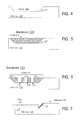
- the cavity is then filled with some material 520 ( FIG. 5 ).
- Layer 520 is then patterned and etched to form grooves 310 ( FIG. 6 ).
- the etch is selective to substrate 130 . Due to the etch selectivity, the 45° sidewall supporting the minors will not be damaged by the etch even though the sidewall is exposed early during the etch.
- the process is tolerant to misalignment between the cavity mask (the etch mask, not shown, used to form the cavity in FIG. 4 ) and the groove mask (not shown) because the cavity mask can be shifted right or left in the view of FIG. 6 relative to the groove mask.
- Cavity 410 ( FIG. 4 ) has a low aspect ratio (height-to-depth ratio), so the etch of cavity 410 can be easily controlled to provide a precise uniform depth throughout the cavity. In some embodiments, the aspect ratio is at most 1:2.
- the etch of layer 520 can also be easily controlled because this etch is selective to substrate 130 serving as an etch stop.
- substrate 130 can be silicon, and layer 520 silicon dioxide.
- the etch selectivity can be improved by forming an additional etch-stop layer on cavity 410 before deposition of layer 520 . In some embodiments, the etch selectivity is at least 2:1.
- the process of FIGS. 4-6 is easy to integrate with other steps that form conductive lines or other circuitry in or over substrate 130 .
- Such circuitry can be formed between the stages of FIGS. 5 and 6 , i.e. after the deposition of layer 520 before the groove etch.
- the wafer is flat at this stage, and many conventional processes for circuit fabrication work better on flat wafers. (We will sometimes refer to substrate 130 together with other elements integral with the substrate as a “wafer”; in some embodiments multiple interposers are simultaneously fabricated in the same wafer.) In particular, wafer handling and photolithography work better with flat wafers.
- the material 520 can be chosen consistently with the processes forming other circuitry.
- the material 520 can be chosen to withstand high temperatures. If mirrors 144 (not shown in FIGS. 4-6 ) or other elements need to be formed of non-refractory metal (such as gold), the metal deposition can be postponed until after the high temperature steps.
- FIG. 7 is a view of an interposer 124 with a mirror 144 and a fiber or fibers 104 in a cross section taken along a fiber 104 .
- the fibers are inserted into grooves 310 from the interposer's left side.
- the cavity 410 does not have a sidewall on that side.
- the cavity is initially formed with the sidewalls on all sides ( FIG. 4 ), but one side is then removed during dicing of wafer 130 . More particularly, one sidewall of cavity 410 is positioned on the wafer's scribe line. This sidewall is removed by the dicing process.
- FIG. 1 shows a vertical cross section of an opto-electrical system according to prior art.
- FIG. 2 is a top view of a part of the system of FIG. 1 .
- FIG. 3 shows a vertical cross section of a part of the system of FIG. 1 .
- FIGS. 4-6 show vertical cross sections of optical interposers during fabrication according to some embodiments of the present invention.
- FIG. 7 shows a vertical cross section of an optical interposer with fibers according to some embodiments of the present invention.
- FIG. 8 shows a vertical cross section of an optical interposer during fabrication according to some embodiments of the present invention.
- FIG. 9 is a top view of an optical interposer during fabrication according to some embodiments of the present invention.
- FIGS. 10 , 11 , 12 , 13 , 14 , 15 , 16 show vertical cross sections of optical interposers during fabrication according to some embodiments of the present invention.
- FIG. 17A is a top view of an optical interposer during fabrication according to some embodiments of the present invention.
- FIG. 17B shows a vertical cross section of an optical interposer during fabrication according to some embodiments of the present invention.
- FIGS. 18 , 19 are top views of optical interposers during fabrication according to some embodiments of the present invention.
- FIG. 20 is a top view of an optical interposer with fibers according to some embodiments of the present invention.
- FIG. 21 is a top view of a module with an optical interposer according to some embodiments of the present invention.
- FIGS. 22 , 23 show vertical sections of modules with optical interposers according to some embodiments of the present invention.
- FIG. 24 is a top view of an optical interposer according to some embodiments of the present invention.
- FIG. 25 is a top view of an optical interposer with fibers according to some embodiments of the present invention.
- FIG. 26 is a top view of a module with an optical interposer according to some embodiments of the present invention.
- FIG. 27 shows possible spacer shapes in top view for optical interposers according to some embodiments of the present invention.
- FIG. 28 is a top view showing some features of an optical interposer with fibers according to some embodiments of the present invention.
- FIGS. 29 , 30 show vertical cross sections of optical interposers during fabrication according to some embodiments of the present invention.
- FIG. 31 is a top view of an optical interposer according to some embodiments of the present invention.
- FIGS. 32 , 33 , 34 , 35 A, 35 B, 35 C, 35 D, 35 E, 35 F, 36 , 37 , 38 , 39 A, 39 B, 39 C show vertical cross sections of optical interposers during fabrication according to some embodiments of the present invention.
- FIG. 40 is a top view of an optical interposer during fabrication according to some embodiments of the present invention.
- FIGS. 41 , 42 show vertical cross sections of optical interposers according to some embodiments of the present invention.
- FIG. 43 is a top view of an optical interposer during fabrication according to some embodiments of the present invention.
- FIG. 8 (cross sectional view) and FIG. 9 (top view) illustrate substrate 130 with cavity 410 at the beginning stages of fabrication of an optical interposer according to some embodiments of the present invention.
- Substrate 130 can be silicon, silicon on insulator (SOI), glass, metal, or other materials.
- substrate 130 is part of a wafer in which multiple interposers are simultaneously fabricated.
- substrate 130 is monocrystalline silicon having a thickness of 750 ⁇ m.
- Substrate 130 is initially planar on top and bottom. Cavity 410 is formed by a masked timed etch. More particularly, substrate 130 is cleaned, and a masking layer 810 is deposited on the entire top surface to provide a hard mask.
- layer 810 is silicon dioxide thermally grown to an exemplary thickness of 1.0 ⁇ m, but silicon nitride and other layers and fabrication processes can also be used. (Layer 810 is optional, and can be omitted; the hard mask may or may not be desirable depending on the type of etch used to form the cavity, the cavity depth, the material of substrate 130 , and possibly other factors.)
- Masking layer 810 is patterned with photoresist (not shown) to define cavity 410 .
- the photoresist is removed, and substrate 130 is etched through the mask opening to form the cavity.
- the cavity has a horizontal bottom surface (parallel to the substrate's bottom surface) and sloped sidewalls 910 . 1 through 910 . 4 that are inclined at an exemplary angle of 45° to the bottom surface of the substrate.
- the mirrors will be formed on one of these sidewalls, e.g. on sidewall 910 . 2 .
- the invention is not limited to a cavity having four sidewalls; the cavity can be non-rectangular in top view, and may have rounded and other shapes.
- An exemplary etch of cavity 410 is wet etch which provides the 45° sidewalls if wafer 130 is a common (100)-silicon wafer.
- a suitable wet etch is KOH with Isopropyl Alcohol as an additive.
- the etch is timed to provide the desired cavity depth.
- the cavity depth is 100 ⁇ m, and the etching time is about 100 minutes.
- Other etching processes can also be used. See e.g. Hsiao et al. cited above.
- the cavity depth can be any suitable value, e.g. 100 to 500 ⁇ m or smaller or larger.
- the cavity is rectangular, and the dimensions of the cavity's top surface are 2.1 mm along the sidewall 910 . 1 and 2.0 mm along the sidewall 910 . 2 , but other shapes and dimensions are possible.
- the aspect ratio of the cavity is thus about 1:21.
- the low aspect ratio is desirable to provide a uniform, highly controllable cavity depth. Other aspect ratios can also be
- etch stop layer 1010 ( FIG. 10 ) is deposited over the substrate to provide an etch stop in subsequent etch of layer 520 ( FIGS. 5 , 6 ).
- layer 520 will be polysilicon
- layer 1010 is silicon dioxide thermally grown on silicon substrate 130 to a thickness of 2.0 ⁇ m or deposited by CVD (e.g. from TEOS). The thickness of layer 810 increases in this step.
- layer 520 is chosen for compatibility with other fabrication processes that will form circuitry in substrate 130 .
- Polysilicon is desirable for its tolerance to high temperatures such as present in thermal oxidation of silicon. Polysilicon is also easy and inexpensive to deposit.
- layer 520 will be used to provide mechanical support for a cantilevered transducer 120 as described below but will not be used to provide semiconductor circuit elements such as transistor regions. Low quality polysilicon and inexpensive deposition methods can therefore be used.
- layer 520 can be metallurgical polysilicon formed by LTCVD (Low Temperature Chemical Vapor Deposition). Another possibility is polysilicon deposited by high temperature (1200° C.) CVD. Other processes can also be used.
- Layer 520 can be amorphous silicon or polysilicon having very small fine size (nano-grain), or can be epitaxially grown silicon, or other kind.
- suitable materials include polyimide and photoresist (especially if high temperatures will not be used). Other materials are also possible.
- one or more (possibly all) process steps that form the circuitry in substrate 130 are performed before or during the deposition of layer 520 , and the material for layer 520 is chosen based on other considerations.
- Layer 520 initially covers the whole wafer, but then is polished by chemical mechanical polishing (CMP) stopping on oxide 810 . See FIG. 11 . Cavity 410 remains filled by layer 520 but layer 520 is removed outside the cavity. In other embodiments, the CMP or other process leaves layer 520 covering the entire wafer, with a planar top surface. (Non-planar top surface is also possible.)
- CMP chemical mechanical polishing
- the wafer Before etching the layer 520 to form the grooves 310 , the wafer is processed to form circuitry for connection to transducer or transducers 120 and possibly for other purposes.
- the wafer is planar at the stage of FIG. 11 , as desirable for many IC fabrication processes. If desired, an additional planar layer (e.g. silicon nitride) can be deposited over the wafer as a protective layer to protect the layer 520 .
- the wafer can be processed to create circuitry 134 ( FIG. 1 ) or any other desired circuitry, including for example circuit elements both at the top and the bottom of substrate 130 , with through-wafer interconnects between such circuit elements. See for example the following U.S. patents incorporated herein by reference:
- a via 1210 ( FIG. 12 ) is formed in the top surface of substrate 130 at each location of a desired through-substrate via (through-silicon via if the substrate is made of silicon). The via initially does not go through the substrate, but is deeper than the substrate's final thickness (the substrate will be thinned as described below).
- a silicon dioxide layer 1220 is grown over the substrate by thermal oxidation, at an exemplary temperature of 1100° C. for 160 minutes to an exemplary thickness of 1.0 ⁇ m. Layer 1220 also forms on polysilicon 520 unless polysilicon 520 is covered by a protective layer described above in connection with FIGS. 10-11 but not shown in the figures. The thermal oxidation increases the thickness of oxide 810 if this oxide is not covered by the protective layer.
- a seed layer 1230 e.g. copper
- a photoresist film 1240 e.g. dry-film-resist
- Copper 1250 is electroplated to fill the vias 1210 and protrude above the resist 1240 .
- FIG. 13 A subsequent stage is illustrated in FIG. 13 . More particularly, copper 1250 is polished by CMP to provide a planar top surface. Then resist 1240 is stripped, and copper layers 1250 and 1230 are polished down by CMP to the level of oxide 1220 . Oxide 1220 becomes exposed. (Both layers 1250 , 1230 remain in vias 1210 but are shown simply at 1250 in some drawings.) Another metal layer 1310 is sputtered on the wafer and patterned photolithographic ally to form conductive lines that will connect the metalized vias 1210 (i.e. the copper in vias 1210 ) to transducer contacts and/or other circuit elements (e.g. transistors, resistors, diodes, capacitors, or other elements that can be formed in the interposer).
- circuit elements e.g. transistors, resistors, diodes, capacitors, or other elements that can be formed in the interposer.
- Metal pads 1310 are also formed on oxide 1220 over cavity 1410 to provide mechanical support for cantilevered transducers as described below. These and other metal pads may or may not be part of electrical circuitry and may or may not be connected to other circuit elements. Additional dielectric and metal layers (not shown) can be deposited to create multiple interconnect layers and other circuit elements for circuitry connected to the transducers and for other circuitry. Then a passivation layer 1330 (e.g. polyimide) is formed to cover the top side of the wafer.
- a passivation layer 1330 e.g. polyimide
- FIG. 14 the wafer is thinned to turn the vias 1210 into through-vias (through holes). Copper 1250 (and 1230 ) and insulator 1220 protrude down from substrate 130 . Then insulator 1410 (e.g. polyimide) is deposited on the bottom surface, and the bottom surface is planarized by CMP which does not remove all of insulator 1410 but exposes the copper. See FIG. 15 .
- insulator 1410 e.g. polyimide
- Metal 1420 (e.g. copper) is deposited (e.g. by physical vapor deposition, “PVD”) on the bottom surface of the wafer. Metal 1420 is patterned photolithographically to provide interconnect lines for connecting the metalized vias to a controller chip (shown in FIGS. 22 , 23 ) that will control the transducers 120 , and possibly to provide other interconnect lines or other circuit elements. Other interconnect layers (not shown) and other circuit elements (e.g. transistors, diodes, resistors, capacitors, etc., not shown) can also be formed at the bottom.
- PVD physical vapor deposition
- a passivation layer 1430 (e.g. polyimide) is deposited on the bottom surface and is patterned photolithographically to form contact openings exposing the metal 1420 . See FIG. 16 .
- the exposed portions of metal 1420 form contact pads that can be soldered or otherwise attached to the controller chip or other circuits.
- FIG. 17A is a top view of the resulting structure
- FIG. 17B shows the wafer's cross section perpendicular to the grooves.
- the wafer is covered with photoresist (not shown), and the photoresist is patterned to define grooves 310 and the contact openings to metal 1310 ( FIG. 16 ).
- Passivation 1330 is etched away through the photoresist openings over the grooves to be formed and in the contact openings. Oxide 1220 becomes exposed over the grooves 310 . (Alternatively, the etch of passivation 1330 can remove the oxide 1220 over the grooves and expose the layer 520 ).
- the photoresist is removed, and another photoresist layer (not shown) is deposited and patterned to define the grooves 310 . If oxide 1220 was not removed over the grooves, it is removed at this time to expose layer 520 in the grooves.
- Layer 520 is etched selectively to the photoresist and to layer 1010 to form the grooves and expose the layer 1010 .
- the groove sidewalls are vertical, but non-vertical sidewalls are formed in other embodiments.
- layer 520 is polysilicon etched by DRIE (deep reactive ion etch), possibly the Bosch process, and layer 1010 is silicon dioxide. The etch selectivity of polysilicon to silicon dioxide is at least 100:1. Other fabrication processes and selectivity values can also be used.
- Exemplary dimensions that can be achieved for rectangular grooves 310 with monocrystalline substrate 130 and polysilicon spacers 520 , using silicon oxide 1010 as an etch stop, are as follows: the groove width is 135 ⁇ m; the groove pitch (the distance between the centers of adjacent grooves) is 250 ⁇ m; the groove depth is 100 ⁇ m. In some embodiments with rectangular grooves, a suitable groove width is 50 to 1000 ⁇ m, the groove pitch is 150 to 2000 ⁇ m, and the groove depth is 100 to 500 ⁇ m. Other ranges are also possible.
- a reflective layer e.g. aluminum, gold, or some other metal
- mirrors 144 FIG. 18
- Transducer 120 and possibly other circuits are connected to the interposer (to metal contacts 1310 , 1420 ).
- transducer 120 is flip-chip attached to the top contacts 1310 of the interposer with solder 1604 or some other means
- controller 1610 is flip-chip attached to the bottom contacts 1420 with solder 1608 or some other means.
- FIG. 21 is the top view;
- FIG. 22 shows a longitudinal cross section along a spacer 520 / 1220 / 1330 between adjacent grooves 310 ;
- FIG. 22B shows a cross section along a fiber 104 .
- Multiple transducers, controllers, and other integrated circuits and discrete circuit elements can be connected to the interposer.
- solder 1604 is also placed on metal 1310 over polysilicon spacers 520 to provide mechanical support for supporting cantilevered transducer chip or chips 120 or other circuits that may overly the cavity 410 .
- the transducer size can therefore be increased without increasing the stress on the transducer and without increasing the overall area of the module.
- the module can be mounted on a PCB or in any other desired way.
- each spacer 520 can be made discontinuous and/or hollow.
- discontinuous spacers can define multiple channels overlying each other, as illustrated in FIG. 24 (top view without fibers and transducers), FIG. 25 (top view with two layers of fibers 104 but without transducers), and FIG. 26 (top view with two layers of fibers 104 and two transducers 120 ).
- contacts 1310 between the grooves are not shown for simplicity.
- Grooves 310 X and fibers 104 X run in the X direction (horizontally in the view of FIGS. 24-26 ) between the spacers. Grooves 310 Y and fibers 104 Y run in the Y direction over the fibers 104 X. Minors 144 on side 910 . 2 are for the bottom fibers 104 X. Minors 144 on side 910 . 1 are for the top fibers 104 Y. Cavity sidewalls 910 . 3 , 910 . 4 are removed during dicing or at some other processing stage.
- Discontinuous spacers are less vulnerable to thermal stresses. They can be formed of metal or other materials. They may have any desired shape.
- FIG. 27 shows some non-limiting examples in top view: A (round spacer), B (parallelogram), C (hexagon), D (half-circle), E (trapezoid), F (half-ring), G (full ring), H (hollow rectangle), and I (hollow circle with a diameter).
- Spacer J is another hollow rectangle, but the spacer is continuous, i.e. running through the whole cavity. Other shapes can also be used.
- the spacers' sidewalls can be vertical or inclined, and can have conical or other shapes.
- spacers 520 between each pair of fibers 104 form a double row of discontinuous spacers.
- Minors 144 can optionally be patterned to be a continuous layer on the cavity sidewall if the spacers do not overly the sidewall.
- the continuous mirror layer can also be provided for continuous spacers.
- FIGS. 29-30 illustrate use of SOI (silicon on insulator) substrate 130 , having monocrystalline silicon layers 130 . 1 , 130 . 2 separated by planar insulating layer 2910 .
- the fabrication process is similar to the processes described above.
- FIGS. 29-30 show the same views, and the same stages of fabrication, as respective FIGS. 8 , 11 .
- the etch of cavity 410 stops on insulator 2920 , and so will the etch of grooves 310 (described above in connection with FIG. 17B ). Highly controllable cavity depth is achieved.
- layer 130 . 2 has (100) orientation, and the cavity etch is a KOH wet etch described above.
- FIG. 31 is similar to FIG. 18 , but mirrors 144 are formed at the groove ends on cavity sidewalls 910 . 2 , 910 . 4 .
- Transducers (not shown) can be mounted on the interposer over all these mirrors, and can be optically coupled to each other by the optical fibers 104 .
- mirrors and transducers can be provided on all the four cavity sides 910 . 1 - 910 . 4 .
- a single transducer chip may have both light emitters and photodetectors.
- the grooves can be curved in the top and/or side views, and can have a varying width.
- the mirrors 144 can be absent since mirrors can be etched into fibers' end faces as described in U.S. Pat. No. 8,031,993 issued Oct. 4, 2011 to Bowen.
- the minors 144 when present, can be planar as described above, or can be elliptic or have other shapes.
- Non-mirror optical elements e.g. prisms, etc. can also be used.
- the spacers can be formed by a subtractive method as shown in FIGS. 32-34 .
- FIG. 32 is similar to FIG. 6 , but layer 520 is patterned to remain at the groove locations, i.e. in regions complimentary to the spacer locations. The patterning uses a selective etch as described above. Then the spaces between features of layer 520 are filled with a material 3410 ( FIG. 33 ).
- This can be any material suitable for the spacers, deposited by any suitable process, e.g. metal deposited over the wafer and then etched off to provide a planar top surface. Other techniques can also be used, e.g. electrodeposition on a seed layer (not shown) formed in the cavity before deposition of layer 520 .
- layer 520 is etched away selectively to layer 3410 ( FIG. 34 ) to form the grooves 310 .
- Layer 3410 provides the spacers between the grooves.
- the subtractive method can be used with an etch-stop layer such as 1010 ( FIG. 17B ) and can be combined with other features described above.
- grooves with optical fibers are provided both at the top and bottom surfaces of the interposer.
- the grooves at each surface can be formed using any techniques described above, including the prior art techniques described in connection with FIGS. 1-3 .
- One exemplary process is as follows. Substrate 130 is thinned to its final thickness. Then V-grooves or other grooves are etched in substrate 130 on both sides, possibly at the same time with a wet etch. Then each side is processed, possibly as the top side in FIG. 1-3 , to finish the interposer fabrication.
- the interposer is formed as follows.
- Substrate 130 is thinned to its final thickness.
- cavities 410 . 1 , 410 . 2 are etched respectively in the top and bottom surfaces of the substrate, possibly simultaneously, using the processes described above or any other suitable processes.
- a mask 810 is used on the top and bottom to define the two cavities.
- Etch stop layer 1010 is formed on the top and bottom surfaces, possibly simultaneously (e.g.
- layer 520 is formed on the top and bottom surfaces of the wafer using the techniques described above or other techniques. This layer is shown as 520 . 1 on the top surface, and as 520 . 2 on the bottom surface.
- the top layer 520 . 1 is planarized as in FIG. 11 , to be removed outside of cavity 410 . 1 .
- the bottom layer may also be planarized, but it covers the whole bottom surface of the wafer.
- the thickness is chosen to accommodate the through-substrate-via process described below, and can be any suitable value.
- a blind via 1210 is formed in the top surface of the wafer by a masked etch of layer 810 and substrate 130 at each location of a desired through-substrate via as described above in connection with FIG. 12 .
- Via 1210 passes through substrate 130 and through layer 810 above and below the substrate and partially, but not completely, passes through layer 520 . 2 .
- vias 1210 are then oxidized and metalized, and conductive lines 1310 and possibly other circuit elements and passivation 1330 are formed on top of the interposer, using processes described above in connection with FIGS. 12-13 .
- the interposer is thinned, by CMP or other processes, to remove the layer 520 . 2 down to the level of oxide 1010 at the interposer bottom.
- Vias 1220 become through holes.
- Copper 1250 (and seed 1230 ) and insulator 1220 protrude down from substrate 130 .
- insulator 1410 e.g. polyimide
- CMP chemical vapor deposition
- Conductive lines 1420 and other circuit elements and passivation 1430 are formed on the interposer bottom as described above in connection with FIGS. 15-16 and illustrated in FIG. 35D .
- FIG. 35E shows an exemplary vertical cross section perpendicular to grooves 310 .
- the cavities 410 . 1 , 410 . 2 do not have to be aligned, i.e. cavity 410 . 1 can be laterally shifted relative to cavity 410 . 2 .
- the grooves 310 also may have different shapes and dimensions. More than one cavity can be provided on top and/or bottom, and the top grooves 310 do not have to be parallel to the bottom grooves.
- FIG. 35F shows an exemplary structure at a stage similar to FIG. 23 , with transducers 120 . 1 , 120 . 2 on top and bottom respectively.
- the two transducers are connected to each other through a metalized via 1210 , but this is not necessary.
- Different transducers can be connected to different vias, or not connected to any vias, and controllers 1610 ( FIG. 22 ) and other circuits can be mounted on the interposer as needed.
- the through vias 1210 are created without first forming blind vias, i.e. the vias 1210 are etched through the interposer wafer right away. Also, the invention is not limited to through vias.
- the “mirror” sidewall 910 . 2 can be formed by a separate etch or other process.
- the minor sidewall 910 . 2 can be at a different angle and/or depth than sidewalls 910 . 1 , 910 . 3 , 910 . 4 of the cavity.
- FIGS. 39A-39C One possible process is illustrated in FIGS. 39A-39C . This process is suitable for a wide variety of substrate materials including monocrystalline silicon and other materials described above. Initially ( FIG. 39A ), cavity 410 is formed with all the sidewalls being vertical or at some other angle.
- the cavity is formed by a masked dry etch with a photoresist mask (not shown, similar to mask 810 in FIG. 8 ). Then ( FIG. 39B ) the photoresist is removed, and sidewall 910 . 2 is etched to change its geometry. Other sidewalls of the cavity may or may not be similarly processed, and either an entire sidewall or only part of a sidewall may be so processed.
- the geometry of sidewall 910 . 2 is defined by mechanical machining, and more particularly using a dicing saw 3910 having a 45° sidewall 3910 A facing the sidewall 910 . 2 .
- Saw 3910 rotates around a horizontal axis 3910 X perpendicular to sidewall 910 . 2 to change the sidewall geometry. Sidewall 910 . 2 acquires a 45° profile matching the saw sidewall 3910 A. See FIG. 39C (vertical cross section) and FIG. 40 (top view).
- the cavity can be filled with layer 520 , possibly after deposition of layer 1010 , and such cavities can be formed both at the top and the bottom of substrate 130 by the process of FIGS. 39A-39C or other processes.
- the sawing or other processing of sidewall 910 . 2 ( FIG. 39B ) is performed to a controlled depth, and in the embodiment of FIG. 39C the depth is less than the depth of cavity 410 .
- This step can be used as a hard stop for fibers 104 to facilitate the fiber alignment as shown in FIG. 41 —the fibers are inserted in grooves 310 so that they abut the step 3930 .
- FIG. 41 does not show oxide 1010 and other features that may or may not be present as in FIGS. 4-38 .
- the mirror sidewall 910 . 2 can be deeper than the rest of the cavity, or can be of the same depth.
- the cavity with grooves 310 and the electrical circuitry can initially be formed in separate wafers, shown as interposers 124 . 1 and 124 . 2 , which are then assembled into a single optical interposer 124 .
- An exemplary fabrication process is as follows.
- Optical interposer 124 . 1 is fabricated by processing a substrate 130 . 1 (monocrystalline silicon or other suitable material) as in FIGS. 8-19 to form cavity 410 and grooves 310 and mirrors 144 , but without electrical circuitry outside the cavity 410 .
- Oxide 1220 , metal 1310 , and passivation 1330 may be present in interposer 124 . 1 in the cavity area as in FIGS. 17A-19 .
- Circuit elements and pads of metal 1310 can thus be formed in the cavity area. Then the wafer is thinned and diced to obtain a structure containing the cavity as shown in top view in FIG. 43 . One or more sidewalls may (but does not have to) be removed in the dicing process as described above in connection with FIG. 19 . Process variations can be used as described above, including the variation of FIGS. 39A-39C .
- interposer 124 . 2 is fabricated by processing a substrate 130 . 2 (monocrystalline silicon or other suitable material) to form electrical circuitry for connection to transducers and other circuits.
- the wafer processing can be as described above in connection with FIGS. 12-16 .
- a cavity 4210 is formed in substrate 130 . 2 .
- Optical interposer 124 . 1 is inserted into this cavity.
- Fibers 104 can be inserted in grooves 310 and suitably affixed (e.g. with adhesive) before or after the attachment of interposer 124 . 1 to interposer 124 . 2 .
- Transducers and other circuits can be attached to combined interposer 124 as described above.
- Interposer 124 . 1 may have discontinuous spacers and/or minors 144 on different sidewalls as FIGS. 24-26 , and interposer 124 . 1 or 124 may have other features described above in connection with FIGS. 4-41 .
- interposer 124 . 2 has cavities 4210 on top and bottom, and a separate interposer or interposers 124 . 1 are inserted into each cavity.
- an optical interposer (e.g. 124 or 124 . 1 ) comprises a top surface having a first cavity therein.
- the first cavity can be 410 in FIG. 4 , or can be the cavity defined by layer 1010 in FIG. 10 or in interposer 124 . 1 of FIG. 42 , i.e. the cavity whose surface is the top surface of layer 1010 .
- the first cavity can be defined by layer 1010 in cavity 410 . 1 or 410 . 2 of FIG. 35A .
- the first cavity may have sidewalls all around (as in FIG. 31 ) or some sidewalls may be removed (as in FIG. 19 or 24 ), i.e. the first cavity may be at an edge of the interposer.
- the optical interposer also comprises one or more first spacers (e.g. 520 , or 3410 , or a combination of 520 (or 520 . 1 or 520 . 2 ) and 1220 in FIG. 17B or 35 E, with or without 1330 ).
- the one or more first spacers are on a surface of the first cavity.
- the one or more first spacers define a plurality of first channels for supporting optical fiber cables.
- the channels can be grooves 310 , or grooves 310 X and 310 Y in FIG. 24 , or other channels. Different channels can run in different directions as in FIG. 24 , perpendicular or at some other angle to each other.
- Each first spacer comprises a bottom region physically contacting the first cavity's surface and made of a different material than at least part of the first cavity's surface.
- the bottom region can be a spacer 520 or 520 . 1 or 520 . 2 , and the first material can be polysilicon.
- the bottom region can also be less than a whole spacer.
- layer 520 is covered by a layer 3610 made of a different material than 520 , possibly of the same material as the cavity surface, and each first spacer can be viewed as made of layers 520 , 3610 to define grooves 310 therebetween.
- layer 3610 can be formed by selective deposition (e.g.
- each first spacer can be the region 520 made of a different material than the cavity surface. In FIGS. 6 and 17B , the bottom region can be an entire spacer 520 which contacts a different material 1010 ( FIG. 17B ) or 130 ( FIG. 6 ).
- the first cavity's surface comprises:
- a sidewall surface comprising one or more sidewall portions extending from the bottom surface upward and laterally outside of the first cavity.
- the sidewall surface can be 910 . 2
- the sidewall portions can be the oxide sidewall portions underlying the metal minors 144 .
- Each first channel has a first end which is adjacent to an associated one of the one or more sidewall portions, each sidewall portion being for providing and/or supporting an optical element (e.g. a minor 144 , or a prism (not shown), or some other optical element) for directing light coming into and/or out of the first channel's respective optical fiber cable.
- an optical element e.g. a minor 144 , or a prism (not shown), or some other optical element
- the first end of each channel is the end adjacent to the corresponding mirror 144 .
- the bottom region overlies and physically contacts the first cavity's bottom surface and is made of a different material than at least part of the first cavity's bottom surface adjacent to the bottom region. In some embodiments, for at least one first spacer, the bottom region overlies and physically contacts the first cavity's sidewall surface and is made of a different material than at least part of the first cavity's sidewall surface adjacent to the bottom region.
- the bottom region 520 of each spacer overlies and physically contacts both the bottom surface and the sidewall surface 910 . 2 supporting the mirrors, the bottom and sidewall surfaces are made of a different material (e.g. polysilicon) than the cavity's surface (made of silicon dioxide for example).
- each optical element is a reflective surface (e.g. mirror 144 ) formed on the associated sidewall portion, the reflective surface being for reflecting light coming into and/or from a respective optical fiber cable in the first channel, the reflective surface having a different reflectivity property than at least one surface of the first cavity.
- mirror 144 may be metal having a different reflective property than the silicon dioxide surface of the cavity.
- the mirrors are provided by the cavity's sidewall surface, not by a separate layer (e.g. metal) on the cavity surface.
- the first cavity's bottom surface is planar, and each reflective surface is a flat surface being at an angle of 45° or some other angle at most 60° to the first cavity's planar bottom surface. (This angle is defined as the angle between the reflective surface and an imaginary extension of the planar bottom surface beyond the reflective surface—see e.g. angle ⁇ in FIG. 4 ).
- At least one sidewall of at least one first spacer is at an angle 90° or some other angle of at least 85° to the first cavity's planar bottom surface.
- This angle is defined as the angle between the first spacer's sidewall and the planar bottom surface underneath the first spacer—see e.g. angle ⁇ in FIG. 37 ).
- the interposer comprises a substrate and a layer on the substrate (e.g. 1010 ) of a different material than the substrate and than the bottom region of each first spacer.
- the layer's top surface provides the first cavity's surface.
- the channels comprise at least two channels running in different directions and overlying one another. See FIG. 24 for example.
- the optical interposer comprises one or more pads over the first spacers, for providing mechanical support to an integrated circuit mounted on the interposer.
- a pad 1310 over spacers 520 is used to support solder 1604 which supports the transducer 120 .
- At least one first spacer protrudes upward to provide mechanical support for at least one of the transducers.
- FIG. 38 showing a structure similar to FIG. 22 but without the metal 1310 and solder 1604 over the cavity.
- Transducer 120 rests on passivation 1330 above spacer 520 .
- layer 520 can be left to protrude upward above substrate 130 .
- Layer 520 can then be etched off outside the cavity as needed to form the electrical circuitry. The upward protrusion of layer 520 at the cavity will result in the upward protrusion of passivation 1330 over the cavity.
- the upward protrusion of passivation 1330 can be provided by patterning passivation 1330 and/or insulation 1220 , and/or depositing and patterning other layers by conventional techniques.
- electrical circuitry is formed in at least one of the first spacers (e.g. transistors, interconnect lines, and other circuitry can be formed in spacers 520 ).
- the optical interposer further comprises a bottom surface having one or more second channels defined therein for supporting optical fiber cables (see e.g. FIG. 35F ), the electrical circuitry comprising circuitry for connection to one or more opto-electrical transducers which are for being optically coupled to the optical fiber cables supported by the second channels.
- the optical interposer's bottom surface comprises a second cavity therein.
- the optical interposer also comprises, when viewed upside down (i.e. with the bottom surface on top), one or more second spacers on the second cavity's surface which define a plurality of the second channels.
- Each second spacer comprises a bottom region physically contacting the second cavity's surface and made of a different material than at least part of the second cavity's surface.
- Some embodiments provide an optical interposer for interfacing one or more optical fiber cables to electrical circuitry, the optical interposer comprising a top surface having a first cavity therein.
- the optical interposer also comprises one or more spacers on a surface of the first cavity, wherein the one or more spacers define a plurality of first channels for supporting optical fiber cables.
- the optical interposer comprises electrical circuitry outside the first cavity, for connection to one or more opto-electrical transducers each of which is for being optically coupled to the optical fiber cables.
- the first cavity comprises a first surface at the end of the first channel (e.g.
- At least one sidewall of at lest one spacer is at an angle of at least 85° to the first cavity's planar bottom surface (the angle being between the spacer's sidewall and the planar bottom surface underneath the spacer).
- Some embodiments provide a method for fabricating an optical interposer.
- the method comprises: forming a first cavity (e.g. 410 . 1 or 410 . 2 ) in a substrate; forming a first layer (e.g. 520 or 520 . 1 or 520 . 2 ) over the first cavity's bottom surface; and patterning the first layer to form one or more spacers in the first cavity, wherein the one or more spacers define a plurality of channels for supporting optical fiber cables.
- the spacers could be formed by the first layer (e.g. 520 ) or by another layer (e.g. 3410 ).
- Patterning the first layer comprises a first etch of the first layer, wherein at least over the first cavity's surface, the first etch terminates based at least in part on etch selectivity to the first cavity's surface.
- the first cavity comprises: a bottom surface; and a sidewall (e.g. 910 . 2 ) extending from the bottom surface upward and laterally outside of the first cavity. At least over the first cavity's sidewall, the first etch terminates based at least in part on etch selectivity to the sidewall.
- Some embodiments provide an optical interposer for interfacing one or more optical fiber cables to electrical circuitry, the optical interposer comprising a first surface and a second surface opposite to the first surface (for example, the top and bottom surfaces in FIG. 35F ).
- the first surface comprises one or more first channels for supporting one or more optical fiber cables.
- the second surface comprises one or more second channels for supporting optical fiber cables.
- the optical interposer comprises electrical circuitry for connection to a plurality of opto-electrical transducers which are for being optically coupled to the optical fiber cables.
- the optical interposer comprises a substrate (e.g. 130 ), and the plurality of channels are formed in recesses in opposite surfaces of the substrate.
- the recesses are defined by the top surface of layers 1010 in cavities 410 . 1 , 410 . 2 .
- the recesses could be individual V-grooves as in FIGS. 1-3 .
- the optical interposer comprises electrical circuitry at the first and second surfaces, and comprises one or more conductive paths passing through the substrate (e.g. metalized vias 1210 ) for interconnecting electrical circuitry at the first surface and electrical circuitry at the second surface.
Abstract
Description
Claims (52)
Priority Applications (13)
| Application Number | Priority Date | Filing Date | Title |
|---|---|---|---|
| US13/362,898 US8757897B2 (en) | 2012-01-10 | 2012-01-31 | Optical interposer |
| US13/454,713 US9323010B2 (en) | 2012-01-10 | 2012-04-24 | Structures formed using monocrystalline silicon and/or other materials for optical and other applications |
| TW101150996A TWI539191B (en) | 2012-01-10 | 2012-12-28 | Optical interposer |
| TW101150997A TWI553368B (en) | 2012-01-10 | 2012-12-28 | Structure comprising substrate including region of monocrystalline silicon and methods for manufacturing substrate and structure |
| PCT/US2013/020578 WO2013106288A1 (en) | 2012-01-10 | 2013-01-07 | Optical interposer |
| CN201380013259.3A CN104169768B (en) | 2012-01-10 | 2013-01-07 | Utilize the structure applied with other for optics that monocrystalline silicon and/or other material are formed |
| KR1020147022311A KR101870490B1 (en) | 2012-01-10 | 2013-01-07 | Structures formed using monocrystalline silicon and/or other materials for optical and other applications |
| EP13700811.6A EP2802915B1 (en) | 2012-01-10 | 2013-01-07 | Optical interposer |
| EP13702514.4A EP2802916B1 (en) | 2012-01-10 | 2013-01-07 | Structures formed using monocrystalline silicon and/or other materials for optical and other applications |
| CN201380013246.6A CN104364688B (en) | 2012-01-10 | 2013-01-07 | Optica insert |
| JP2014552231A JP5970081B2 (en) | 2012-01-10 | 2013-01-07 | Structures formed using single crystal silicon and / or other materials for optical and other applications |
| KR1020147022313A KR101955060B1 (en) | 2012-01-10 | 2013-01-07 | Optical interposer |
| PCT/US2013/020562 WO2013106285A2 (en) | 2012-01-10 | 2013-01-07 | Structures formed using monocrystalline silicon and/or other materials for optical and other applications |
Applications Claiming Priority (2)
| Application Number | Priority Date | Filing Date | Title |
|---|---|---|---|
| US201261585217P | 2012-01-10 | 2012-01-10 | |
| US13/362,898 US8757897B2 (en) | 2012-01-10 | 2012-01-31 | Optical interposer |
Related Child Applications (1)
| Application Number | Title | Priority Date | Filing Date |
|---|---|---|---|
| US13/454,713 Continuation-In-Part US9323010B2 (en) | 2012-01-10 | 2012-04-24 | Structures formed using monocrystalline silicon and/or other materials for optical and other applications |
Publications (2)
| Publication Number | Publication Date |
|---|---|
| US20130177281A1 US20130177281A1 (en) | 2013-07-11 |
| US8757897B2 true US8757897B2 (en) | 2014-06-24 |
Family
ID=48743991
Family Applications (1)
| Application Number | Title | Priority Date | Filing Date |
|---|---|---|---|
| US13/362,898 Active 2032-08-29 US8757897B2 (en) | 2012-01-10 | 2012-01-31 | Optical interposer |
Country Status (1)
| Country | Link |
|---|---|
| US (1) | US8757897B2 (en) |
Cited By (6)
| Publication number | Priority date | Publication date | Assignee | Title |
|---|---|---|---|---|
| US20130330033A1 (en) * | 2012-06-12 | 2013-12-12 | Futurewei Technologies, Inc. | Tsv substrate with mirror and its application in high-speed optoelectronic packaging |
| US20140270630A1 (en) * | 2010-08-26 | 2014-09-18 | Vi Systems Gmbh | Opto-electronic assembly for parallel high speed transmission |
| CN104364688A (en) * | 2012-01-10 | 2015-02-18 | 伊文萨斯公司 | Optical interposer |
| US9529163B2 (en) * | 2013-05-07 | 2016-12-27 | Hitachi Metals, Ltd. | Optical wiring substrate, manufacturing method of optical wiring substrate and optical module |
| US9798088B2 (en) * | 2015-11-05 | 2017-10-24 | Globalfoundries Inc. | Barrier structures for underfill blockout regions |
| US11067747B2 (en) | 2017-07-28 | 2021-07-20 | Cisco Technology, Inc. | Deposited Si photodetectors for silicon nitride waveguide based optical interposer |
Families Citing this family (9)
| Publication number | Priority date | Publication date | Assignee | Title |
|---|---|---|---|---|
| US20140367816A1 (en) * | 2013-06-12 | 2014-12-18 | Avago Technologies General Ip (Singapore) Pte.Ltd. | Photodetector device having light-collecting optical microstructure |
| US9246592B2 (en) * | 2013-08-19 | 2016-01-26 | International Business Machines Corporation | Structured substrate for optical fiber alignment |
| US9397051B2 (en) | 2013-12-03 | 2016-07-19 | Invensas Corporation | Warpage reduction in structures with electrical circuitry |
| US9395491B2 (en) | 2014-02-05 | 2016-07-19 | Aurrion, Inc. | Shielding regions for photonic integrated circuits |
| WO2016063163A1 (en) * | 2014-10-23 | 2016-04-28 | Koninklijke Philips N.V. | Shape sensing for flexible ultrasound transducers |
| US10641976B2 (en) * | 2017-02-23 | 2020-05-05 | Ayar Labs, Inc. | Apparatus for optical fiber-to-photonic chip connection and associated methods |
| WO2018152647A1 (en) * | 2017-02-24 | 2018-08-30 | Reflex Photonics Inc. | Wirebonding for side-packaged optical engine |
| US10209477B1 (en) * | 2017-05-25 | 2019-02-19 | Lockheed Martin Coherent Technologies, Inc. | Systems and methods for reconfigurable micro-optic assemblies |
| US11262506B1 (en) * | 2020-08-07 | 2022-03-01 | Advanced Semiconductor Engineering, Inc. | Recessed portion in a substrate and method of forming the same |
Citations (40)
| Publication number | Priority date | Publication date | Assignee | Title |
|---|---|---|---|---|
| US3761782A (en) | 1971-05-19 | 1973-09-25 | Signetics Corp | Semiconductor structure, assembly and method |
| US4905523A (en) | 1987-04-24 | 1990-03-06 | Wacoh Corporation | Force detector and moment detector using resistance element |
| US5229647A (en) | 1991-03-27 | 1993-07-20 | Micron Technology, Inc. | High density data storage using stacked wafers |
| US5357103A (en) | 1991-10-02 | 1994-10-18 | Sumitomo Electric Industries, Inc. | Light receiving module with optical fiber coupling |
| EP0827211A2 (en) | 1996-08-28 | 1998-03-04 | Hewlett-Packard Company | A photo detector with an integrated mirror and a method of making the same |
| US5987202A (en) * | 1995-01-18 | 1999-11-16 | Robert Bosch Gmbh | Arrangement for converting optical signals into electrical signals and method of producing the arrangement |
| US5998234A (en) | 1996-03-29 | 1999-12-07 | Denso Corporation | Method of producing semiconductor device by dicing |
| EP0987769A2 (en) | 1998-09-18 | 2000-03-22 | Sumitomo Electric Industries, Ltd. | Photodiode module |
| US6115521A (en) * | 1998-05-07 | 2000-09-05 | Trw Inc. | Fiber/waveguide-mirror-lens alignment device |
| US6246026B1 (en) | 1998-09-18 | 2001-06-12 | The Whitaker Corporation | Process for cutting an optical fiber |
| US6332719B1 (en) | 1997-06-25 | 2001-12-25 | Matsushita Electric Industrial Co., Ltd. | Optical transmitter/receiver apparatus, method for fabricating the same and optical semiconductor module |
| US20020015920A1 (en) | 2000-08-07 | 2002-02-07 | Steinberg Dan A. | Fiber optic chip with lenslet array and method of fabrication |
| US6439703B1 (en) | 2000-12-29 | 2002-08-27 | Eastman Kodak Company | CMOS/MEMS integrated ink jet print head with silicon based lateral flow nozzle architecture and method of forming same |
| US20030034438A1 (en) | 1998-11-25 | 2003-02-20 | Sherrer David W. | Optoelectronic device-optical fiber connector having micromachined pit for passive alignment of the optoelectronic device |
| US20030118288A1 (en) * | 2001-12-04 | 2003-06-26 | Tsuguhiro Korenaga | Optical package substrate and optical device |
| US20030123819A1 (en) | 2001-12-25 | 2003-07-03 | Hiromi Nakanishi | Optical communications module |
| US6625357B2 (en) | 1999-03-29 | 2003-09-23 | Tyco Electronics Corporation | Method for fabricating fiducials for passive alignment of opto-electronic devices |
| US20030210853A1 (en) * | 2002-05-10 | 2003-11-13 | Yoshichika Kato | Optical switch |
| US20040067025A1 (en) * | 2002-05-09 | 2004-04-08 | Akira Haraguchi | Optical device |
| US6787916B2 (en) | 2001-09-13 | 2004-09-07 | Tru-Si Technologies, Inc. | Structures having a substrate with a cavity and having an integrated circuit bonded to a contact pad located in the cavity |
| US6897148B2 (en) | 2003-04-09 | 2005-05-24 | Tru-Si Technologies, Inc. | Electroplating and electroless plating of conductive materials into openings, and structures obtained thereby |
| US20050196095A1 (en) * | 2004-01-22 | 2005-09-08 | Seiji Karashima | Fabrication method for optical transmission channel board, optical transmission channel board, board with built-in optical transmission channel, fabrication method for board with built-in optical transmission channel, and data processing apparatus |
| US6958285B2 (en) | 2001-02-22 | 2005-10-25 | Tru-Si Technologies, Inc. | Methods of manufacturing devices having substrates with opening passing through the substrates and conductors in the openings |
| US20060022289A1 (en) * | 2002-04-16 | 2006-02-02 | Xloom Photonics, Ltd. | Electro-optical circuitry having integrated connector and methods for the production thereof |
| US7001825B2 (en) | 2001-02-22 | 2006-02-21 | Tru-Si Technologies, Inc. | Semiconductor structures having multiple conductive layers in an opening, and methods for fabricating same |
| US7034401B2 (en) | 2003-12-17 | 2006-04-25 | Tru-Si Technologies, Inc. | Packaging substrates for integrated circuits and soldering methods |
| US7157016B2 (en) * | 2003-05-23 | 2007-01-02 | Rohm And Haas Electronic Materials Llc | Etching process for micromachining crystalline materials and devices fabricated thereby |
| US7173327B2 (en) | 2002-04-18 | 2007-02-06 | Tru-Si Technologies, Inc. | Clock distribution networks and conductive lines in semiconductor integrated circuits |
| US20070036496A1 (en) * | 2005-08-15 | 2007-02-15 | Rohm And Haas Electronic Materials Llc | Bonding methods and optical assemblies |
| US7186586B2 (en) | 2003-12-17 | 2007-03-06 | Tru-Si Technologies, Inc. | Integrated circuits and packaging substrates with cavities, and attachment methods including insertion of protruding contact pads into cavities |
| US20070189659A1 (en) * | 2006-01-29 | 2007-08-16 | Jeng-Jye Shau | Thin Film Optical Patterning Devices |
| US20080290524A1 (en) | 2007-05-25 | 2008-11-27 | International Business Machines Corporation | Through via in ultra high resistivity wafer and related methods |
| US20100221488A1 (en) | 2005-06-10 | 2010-09-02 | Protochips, Inc. | Reusable template for creation of thin films; method of making and using template; and thin films produced from template |
| WO2010105369A1 (en) | 2009-03-20 | 2010-09-23 | Reflex Photonics Inc. | A two dimensional optical connector |
| US20100247042A1 (en) * | 2009-03-30 | 2010-09-30 | Hitachi Cable, Ltd. | Optical connector and fiber module |
| US20110075965A1 (en) | 2009-09-30 | 2011-03-31 | Demeritt Jeffery Alan | Channeled Substrates For Integrated Optical Devices Employing Optical Fibers |
| US7964508B2 (en) | 2006-05-05 | 2011-06-21 | Allvia, Inc. | Dielectric trenches, nickel/tantalum oxide structures, and chemical mechanical polishing techniques |
| US8031993B2 (en) | 2009-07-28 | 2011-10-04 | Tyco Electronics Corporation | Optical fiber interconnect device |
| US20110311189A1 (en) | 2009-02-10 | 2011-12-22 | Tyco Electronics Raychem Bvba | Insert for an optical fiber assembly and optical fiber assembly using such an insert |
| US20120060605A1 (en) | 2010-09-09 | 2012-03-15 | Ming-Ching Wu | Mems sensor capable of sensing acceleration and pressure |
-
2012
- 2012-01-31 US US13/362,898 patent/US8757897B2/en active Active
Patent Citations (44)
| Publication number | Priority date | Publication date | Assignee | Title |
|---|---|---|---|---|
| US3761782A (en) | 1971-05-19 | 1973-09-25 | Signetics Corp | Semiconductor structure, assembly and method |
| US4905523A (en) | 1987-04-24 | 1990-03-06 | Wacoh Corporation | Force detector and moment detector using resistance element |
| US5229647A (en) | 1991-03-27 | 1993-07-20 | Micron Technology, Inc. | High density data storage using stacked wafers |
| US5357103A (en) | 1991-10-02 | 1994-10-18 | Sumitomo Electric Industries, Inc. | Light receiving module with optical fiber coupling |
| US5987202A (en) * | 1995-01-18 | 1999-11-16 | Robert Bosch Gmbh | Arrangement for converting optical signals into electrical signals and method of producing the arrangement |
| US5998234A (en) | 1996-03-29 | 1999-12-07 | Denso Corporation | Method of producing semiconductor device by dicing |
| EP0827211A2 (en) | 1996-08-28 | 1998-03-04 | Hewlett-Packard Company | A photo detector with an integrated mirror and a method of making the same |
| US6332719B1 (en) | 1997-06-25 | 2001-12-25 | Matsushita Electric Industrial Co., Ltd. | Optical transmitter/receiver apparatus, method for fabricating the same and optical semiconductor module |
| US6115521A (en) * | 1998-05-07 | 2000-09-05 | Trw Inc. | Fiber/waveguide-mirror-lens alignment device |
| EP0987769A2 (en) | 1998-09-18 | 2000-03-22 | Sumitomo Electric Industries, Ltd. | Photodiode module |
| US6246026B1 (en) | 1998-09-18 | 2001-06-12 | The Whitaker Corporation | Process for cutting an optical fiber |
| US20030034438A1 (en) | 1998-11-25 | 2003-02-20 | Sherrer David W. | Optoelectronic device-optical fiber connector having micromachined pit for passive alignment of the optoelectronic device |
| US6625357B2 (en) | 1999-03-29 | 2003-09-23 | Tyco Electronics Corporation | Method for fabricating fiducials for passive alignment of opto-electronic devices |
| US6933536B2 (en) | 1999-03-29 | 2005-08-23 | Tyco Electronics Corporation | Method for fabricating fiducials for passive alignment of opto-electronic devices |
| US20020015920A1 (en) | 2000-08-07 | 2002-02-07 | Steinberg Dan A. | Fiber optic chip with lenslet array and method of fabrication |
| US6439703B1 (en) | 2000-12-29 | 2002-08-27 | Eastman Kodak Company | CMOS/MEMS integrated ink jet print head with silicon based lateral flow nozzle architecture and method of forming same |
| US7001825B2 (en) | 2001-02-22 | 2006-02-21 | Tru-Si Technologies, Inc. | Semiconductor structures having multiple conductive layers in an opening, and methods for fabricating same |
| US6958285B2 (en) | 2001-02-22 | 2005-10-25 | Tru-Si Technologies, Inc. | Methods of manufacturing devices having substrates with opening passing through the substrates and conductors in the openings |
| US6787916B2 (en) | 2001-09-13 | 2004-09-07 | Tru-Si Technologies, Inc. | Structures having a substrate with a cavity and having an integrated circuit bonded to a contact pad located in the cavity |
| US20030118288A1 (en) * | 2001-12-04 | 2003-06-26 | Tsuguhiro Korenaga | Optical package substrate and optical device |
| US20030123819A1 (en) | 2001-12-25 | 2003-07-03 | Hiromi Nakanishi | Optical communications module |
| US20060022289A1 (en) * | 2002-04-16 | 2006-02-02 | Xloom Photonics, Ltd. | Electro-optical circuitry having integrated connector and methods for the production thereof |
| US7173327B2 (en) | 2002-04-18 | 2007-02-06 | Tru-Si Technologies, Inc. | Clock distribution networks and conductive lines in semiconductor integrated circuits |
| US20040067025A1 (en) * | 2002-05-09 | 2004-04-08 | Akira Haraguchi | Optical device |
| US20030210853A1 (en) * | 2002-05-10 | 2003-11-13 | Yoshichika Kato | Optical switch |
| US6897148B2 (en) | 2003-04-09 | 2005-05-24 | Tru-Si Technologies, Inc. | Electroplating and electroless plating of conductive materials into openings, and structures obtained thereby |
| US7521360B2 (en) | 2003-04-09 | 2009-04-21 | Tru-Si Technologies, Inc. | Electroplating and electroless plating of conductive materials into openings, and structures obtained thereby |
| US7157016B2 (en) * | 2003-05-23 | 2007-01-02 | Rohm And Haas Electronic Materials Llc | Etching process for micromachining crystalline materials and devices fabricated thereby |
| US7034401B2 (en) | 2003-12-17 | 2006-04-25 | Tru-Si Technologies, Inc. | Packaging substrates for integrated circuits and soldering methods |
| US7060601B2 (en) | 2003-12-17 | 2006-06-13 | Tru-Si Technologies, Inc. | Packaging substrates for integrated circuits and soldering methods |
| US7241675B2 (en) | 2003-12-17 | 2007-07-10 | Tru-Si Technologies, Inc. | Attachment of integrated circuit structures and other substrates to substrates with vias |
| US7186586B2 (en) | 2003-12-17 | 2007-03-06 | Tru-Si Technologies, Inc. | Integrated circuits and packaging substrates with cavities, and attachment methods including insertion of protruding contact pads into cavities |
| US20050196095A1 (en) * | 2004-01-22 | 2005-09-08 | Seiji Karashima | Fabrication method for optical transmission channel board, optical transmission channel board, board with built-in optical transmission channel, fabrication method for board with built-in optical transmission channel, and data processing apparatus |
| US20100221488A1 (en) | 2005-06-10 | 2010-09-02 | Protochips, Inc. | Reusable template for creation of thin films; method of making and using template; and thin films produced from template |
| US20070036496A1 (en) * | 2005-08-15 | 2007-02-15 | Rohm And Haas Electronic Materials Llc | Bonding methods and optical assemblies |
| US20070189659A1 (en) * | 2006-01-29 | 2007-08-16 | Jeng-Jye Shau | Thin Film Optical Patterning Devices |
| US7964508B2 (en) | 2006-05-05 | 2011-06-21 | Allvia, Inc. | Dielectric trenches, nickel/tantalum oxide structures, and chemical mechanical polishing techniques |
| US20080290524A1 (en) | 2007-05-25 | 2008-11-27 | International Business Machines Corporation | Through via in ultra high resistivity wafer and related methods |
| US20110311189A1 (en) | 2009-02-10 | 2011-12-22 | Tyco Electronics Raychem Bvba | Insert for an optical fiber assembly and optical fiber assembly using such an insert |
| WO2010105369A1 (en) | 2009-03-20 | 2010-09-23 | Reflex Photonics Inc. | A two dimensional optical connector |
| US20100247042A1 (en) * | 2009-03-30 | 2010-09-30 | Hitachi Cable, Ltd. | Optical connector and fiber module |
| US8031993B2 (en) | 2009-07-28 | 2011-10-04 | Tyco Electronics Corporation | Optical fiber interconnect device |
| US20110075965A1 (en) | 2009-09-30 | 2011-03-31 | Demeritt Jeffery Alan | Channeled Substrates For Integrated Optical Devices Employing Optical Fibers |
| US20120060605A1 (en) | 2010-09-09 | 2012-03-15 | Ming-Ching Wu | Mems sensor capable of sensing acceleration and pressure |
Non-Patent Citations (21)
| Title |
|---|
| Amini, B. Vakili et al. "Sub-Micro-Gravity Capacitive SOI Microaccelerometers," The 13th International Conference on Solid-State Sensors, Actuators and Microsystems, Seoul, Korea, Jun. 5-9, 2005, pp. 515-518. |
| Bauer, Tomas "High Density Through Wafer Via Technology," Silex Microsystems, NSTI-Nanotech 2007, www.nsti.org, ISBN 1420061844 vol. 3, 2007, pp. 116-119. |
| Bellew, Colby L. et al. "An SOI Process for Fabrication of Solar Cells, Transistors and Electrostatic Actuators," The 12th International Conference on Solid State Sensors, Actuators and Microsystems, Boston, Jun. 8-12, 2003, pp. 1075-1079. |
| D.J. Hayes et al., "Printing System for MEMS Packaging", Proceedings, SPIE Conference on Micromachining and Microfabrication, Oct. 2001. |
| H. Hsiao et al., "Compact and passive-alignment 4-channel × 2.5-Gbps optical interconnect modules based on silicon optical benches with 45° micro-reflectors", Optics Express, vol. 17, No. 26, Dec. 21, 2009. |
| I. Zubel et al., "Micromirrors inclined at 45° towards Si substrates fabricated by anisotropic etching", Optica Applicata, vol. XLI, No. 2, 2011. |
| International Search Report and Written Opinion in corresponding International Application No. PCT/2013/020578 dated Apr. 24, 2013. |
| Invitation to Pay Additional Fees and, Where Applicable, Protest Fee in corresponding International Application No. PCT/US2013/020562 dated Apr. 23, 2013. |
| J.B. Breedis, "Monte Carlo Tolerance Analysis of a Passively Aligned Silicon Waferboard Package", 2001 Electronic Components and Technology Conference Proceedings, 2001. |
| Kosenko et al., U.S. Appl. No. 13/042,186, filed Mar. 7, 2011, 34 pages. |
| Kosenko et al., U.S. Appl. No. 13/181,006, filed Jul. 12, 2011, 38 pages. |
| Long-Sun Huang, "Silicon Bulk Micromachining in MEMS Packaging and Optical Applications", Dissertation submitted for the degree Doctor of Philosophy in Mechanical Engineering, University of California, Los Angeles, 1999. |
| M.J. Madou, "MEMS Fabrication", in The MEMS handbook, Chapter 16, edited by Mohamed Gad-el-Hak, CRC Press, 2001. |
| PCT Notification of Transmittal of the International Search Report and the Written Opinion of the International Searching Authority or the Declaration, International Search Report, and Written Opinion of the International Searching Authority in PCT/US2013/020562, dated Jul. 19, 2013, 17 pages. |
| Properties of silicon and silicon wafers, http://www.el-cat.com/silicon-properties.htm, no later than Mar. 14, 2012. |
| Sekimura, M., Anisotropic Etching of Surfactant-Added TMAH Solution, Micro Electro Mechanical Systems, 1999, MEMS'99, Twelfth IEEE International Conference in Orlando, FL USA Jan. 17-21, 1999, Piscataway, NJ USA, IEEE, US Jan. 17, 1999, pp. 650-655, XP010321781, ISBN: 978-07803-5194-3 p. 655; figure 13. |
| T. Bowen et al., "Silicon Interposer for Compact Right Angle Coupling of Flip Chip VCSEL and Detector Arrays to Multi-Facet Endface Optical Fibers", Pan Pacific Symposium Conference Proceedings, Jan. 18, 2011. |
| Thevenoud, J-M. et al, "DRIE Technology: From Micro to Nanoapplications," Alcatel Micro Machining Systems, ESIEE, no later than Jun. 12, 2011, pp. 1-8. |
| Thru-Silicon Vias, Current State of the Technology, Jan. 30, 2011, 4 pages. |
| Wikipedia File: Silicon-unit-cell-3D-balls.png, http://en.wikipedia.org/wiki/File:Silicon-unit-cell-3D-balls.png, no later than Mar. 14, 2012. |
| X. Zheng et al., "Optical proximity communication using reflective mirros", Optics Express, vol. 16, No. 19, Sep. 15, 2008. |
Cited By (7)
| Publication number | Priority date | Publication date | Assignee | Title |
|---|---|---|---|---|
| US20140270630A1 (en) * | 2010-08-26 | 2014-09-18 | Vi Systems Gmbh | Opto-electronic assembly for parallel high speed transmission |
| US9151918B2 (en) * | 2010-08-26 | 2015-10-06 | Vi Systems Gmbh | Opto-electronic assembly for parallel high speed transmission |
| CN104364688A (en) * | 2012-01-10 | 2015-02-18 | 伊文萨斯公司 | Optical interposer |
| US20130330033A1 (en) * | 2012-06-12 | 2013-12-12 | Futurewei Technologies, Inc. | Tsv substrate with mirror and its application in high-speed optoelectronic packaging |
| US9529163B2 (en) * | 2013-05-07 | 2016-12-27 | Hitachi Metals, Ltd. | Optical wiring substrate, manufacturing method of optical wiring substrate and optical module |
| US9798088B2 (en) * | 2015-11-05 | 2017-10-24 | Globalfoundries Inc. | Barrier structures for underfill blockout regions |
| US11067747B2 (en) | 2017-07-28 | 2021-07-20 | Cisco Technology, Inc. | Deposited Si photodetectors for silicon nitride waveguide based optical interposer |
Also Published As
| Publication number | Publication date |
|---|---|
| US20130177281A1 (en) | 2013-07-11 |
Similar Documents
| Publication | Publication Date | Title |
|---|---|---|
| US8757897B2 (en) | Optical interposer | |
| EP2802915B1 (en) | Optical interposer | |
| EP1556723B1 (en) | Optoelectronic package and fabrication method | |
| KR100481023B1 (en) | Optical device with chip level precision alignment | |
| TWI648563B (en) | Integrated module and forming method thereof | |
| US6707161B2 (en) | Optical module package of flip chip bonding | |
| US6828606B2 (en) | Substrate with embedded free space optical interconnects | |
| US5534442A (en) | Process of providing uniform photoresist thickness on an opto-electronic device | |
| US10564352B1 (en) | Photonic integrated circuit bonded with interposer | |
| JP2014522999A (en) | Optical interposer with common inclined surface | |
| KR20140119001A (en) | Glass-silicon wafer-stacked opto-electronic platforms | |
| KR100211985B1 (en) | Micro mirror for hybrid optical integration circuit and manufacturing method thereof, micro mirror-optical detector assembly and hybrid optical integrating circuit assembly for optical receiving | |
| JP2004507793A (en) | Optical bond wire interconnect and method of forming same | |
| JPH11337777A (en) | Optical element packaging substrate and optical element packaging structure |
Legal Events
| Date | Code | Title | Description |
|---|---|---|---|
| AS | Assignment |
Owner name: INVENSAS CORPORATION, CALIFORNIA Free format text: ASSIGNMENT OF ASSIGNORS INTEREST;ASSIGNORS:KOSENKO, VALENTIN;MCBAIN, EDWARD LEE;UZOH, CYPRIAN EMEKA;AND OTHERS;SIGNING DATES FROM 20120306 TO 20120403;REEL/FRAME:027990/0715 |
|
| AS | Assignment |
Owner name: INVENSAS CORPORATION, CALIFORNIA Free format text: ASSIGNMENT OF ASSIGNORS INTEREST;ASSIGNOR:ALLVIA, INC.;REEL/FRAME:028876/0168 Effective date: 20120824 Owner name: INVENSAS CORPORATION, CALIFORNIA Free format text: ASSIGNMENT OF ASSIGNORS INTEREST;ASSIGNORS:UZOH, CYPRIAN EMEKA;MONADGEMI, PEZHMAN;SIGNING DATES FROM 20120807 TO 20120820;REEL/FRAME:028876/0134 Owner name: ALLVIA, INC., CALIFORNIA Free format text: ASSIGNMENT OF ASSIGNORS INTEREST;ASSIGNORS:KOSENKO, VALENTIN;MCBAIN, EDWARD LEE;SAVASTIOUK, SERGEY;SIGNING DATES FROM 20120823 TO 20120826;REEL/FRAME:028876/0068 |
|
| STCF | Information on status: patent grant |
Free format text: PATENTED CASE |
|
| CC | Certificate of correction | ||
| CC | Certificate of correction | ||
| AS | Assignment |
Owner name: ROYAL BANK OF CANADA, AS COLLATERAL AGENT, CANADA Free format text: SECURITY INTEREST;ASSIGNORS:INVENSAS CORPORATION;TESSERA, INC.;TESSERA ADVANCED TECHNOLOGIES, INC.;AND OTHERS;REEL/FRAME:040797/0001 Effective date: 20161201 |
|
| MAFP | Maintenance fee payment |
Free format text: PAYMENT OF MAINTENANCE FEE, 4TH YEAR, LARGE ENTITY (ORIGINAL EVENT CODE: M1551) Year of fee payment: 4 |
|
| AS | Assignment |
Owner name: BANK OF AMERICA, N.A., NORTH CAROLINA Free format text: SECURITY INTEREST;ASSIGNORS:ROVI SOLUTIONS CORPORATION;ROVI TECHNOLOGIES CORPORATION;ROVI GUIDES, INC.;AND OTHERS;REEL/FRAME:053468/0001 Effective date: 20200601 |
|
| AS | Assignment |
Owner name: IBIQUITY DIGITAL CORPORATION, MARYLAND Free format text: RELEASE BY SECURED PARTY;ASSIGNOR:ROYAL BANK OF CANADA;REEL/FRAME:052920/0001 Effective date: 20200601 Owner name: INVENSAS CORPORATION, CALIFORNIA Free format text: RELEASE BY SECURED PARTY;ASSIGNOR:ROYAL BANK OF CANADA;REEL/FRAME:052920/0001 Effective date: 20200601 Owner name: DTS, INC., CALIFORNIA Free format text: RELEASE BY SECURED PARTY;ASSIGNOR:ROYAL BANK OF CANADA;REEL/FRAME:052920/0001 Effective date: 20200601 Owner name: TESSERA ADVANCED TECHNOLOGIES, INC, CALIFORNIA Free format text: RELEASE BY SECURED PARTY;ASSIGNOR:ROYAL BANK OF CANADA;REEL/FRAME:052920/0001 Effective date: 20200601 Owner name: INVENSAS BONDING TECHNOLOGIES, INC. (F/K/A ZIPTRONIX, INC.), CALIFORNIA Free format text: RELEASE BY SECURED PARTY;ASSIGNOR:ROYAL BANK OF CANADA;REEL/FRAME:052920/0001 Effective date: 20200601 Owner name: PHORUS, INC., CALIFORNIA Free format text: RELEASE BY SECURED PARTY;ASSIGNOR:ROYAL BANK OF CANADA;REEL/FRAME:052920/0001 Effective date: 20200601 Owner name: DTS LLC, CALIFORNIA Free format text: RELEASE BY SECURED PARTY;ASSIGNOR:ROYAL BANK OF CANADA;REEL/FRAME:052920/0001 Effective date: 20200601 Owner name: TESSERA, INC., CALIFORNIA Free format text: RELEASE BY SECURED PARTY;ASSIGNOR:ROYAL BANK OF CANADA;REEL/FRAME:052920/0001 Effective date: 20200601 Owner name: FOTONATION CORPORATION (F/K/A DIGITALOPTICS CORPORATION AND F/K/A DIGITALOPTICS CORPORATION MEMS), CALIFORNIA Free format text: RELEASE BY SECURED PARTY;ASSIGNOR:ROYAL BANK OF CANADA;REEL/FRAME:052920/0001 Effective date: 20200601 |
|
| MAFP | Maintenance fee payment |
Free format text: PAYMENT OF MAINTENANCE FEE, 8TH YEAR, LARGE ENTITY (ORIGINAL EVENT CODE: M1552); ENTITY STATUS OF PATENT OWNER: LARGE ENTITY Year of fee payment: 8 |