US8752449B2 - Substrate transport apparatus with multiple movable arms utilizing a mechanical switch mechanism - Google Patents
Substrate transport apparatus with multiple movable arms utilizing a mechanical switch mechanism Download PDFInfo
- Publication number
- US8752449B2 US8752449B2 US12/117,415 US11741508A US8752449B2 US 8752449 B2 US8752449 B2 US 8752449B2 US 11741508 A US11741508 A US 11741508A US 8752449 B2 US8752449 B2 US 8752449B2
- Authority
- US
- United States
- Prior art keywords
- arm
- arms
- substrate transport
- drive
- transport apparatus
- Prior art date
- Legal status (The legal status is an assumption and is not a legal conclusion. Google has not performed a legal analysis and makes no representation as to the accuracy of the status listed.)
- Active, expires
Links
Images


Classifications
-
- H—ELECTRICITY
- H01—ELECTRIC ELEMENTS
- H01L—SEMICONDUCTOR DEVICES NOT COVERED BY CLASS H10
- H01L21/00—Processes or apparatus adapted for the manufacture or treatment of semiconductor or solid state devices or of parts thereof
- H01L21/67—Apparatus specially adapted for handling semiconductor or electric solid state devices during manufacture or treatment thereof; Apparatus specially adapted for handling wafers during manufacture or treatment of semiconductor or electric solid state devices or components ; Apparatus not specifically provided for elsewhere
- H01L21/677—Apparatus specially adapted for handling semiconductor or electric solid state devices during manufacture or treatment thereof; Apparatus specially adapted for handling wafers during manufacture or treatment of semiconductor or electric solid state devices or components ; Apparatus not specifically provided for elsewhere for conveying, e.g. between different workstations
- H01L21/67739—Apparatus specially adapted for handling semiconductor or electric solid state devices during manufacture or treatment thereof; Apparatus specially adapted for handling wafers during manufacture or treatment of semiconductor or electric solid state devices or components ; Apparatus not specifically provided for elsewhere for conveying, e.g. between different workstations into and out of processing chamber
- H01L21/67742—Mechanical parts of transfer devices
-
- B—PERFORMING OPERATIONS; TRANSPORTING
- B25—HAND TOOLS; PORTABLE POWER-DRIVEN TOOLS; MANIPULATORS
- B25J—MANIPULATORS; CHAMBERS PROVIDED WITH MANIPULATION DEVICES
- B25J9/00—Programme-controlled manipulators
- B25J9/10—Programme-controlled manipulators characterised by positioning means for manipulator elements
- B25J9/106—Programme-controlled manipulators characterised by positioning means for manipulator elements with articulated links
-
- B—PERFORMING OPERATIONS; TRANSPORTING
- B25—HAND TOOLS; PORTABLE POWER-DRIVEN TOOLS; MANIPULATORS
- B25J—MANIPULATORS; CHAMBERS PROVIDED WITH MANIPULATION DEVICES
- B25J11/00—Manipulators not otherwise provided for
- B25J11/0095—Manipulators transporting wafers
-
- B—PERFORMING OPERATIONS; TRANSPORTING
- B25—HAND TOOLS; PORTABLE POWER-DRIVEN TOOLS; MANIPULATORS
- B25J—MANIPULATORS; CHAMBERS PROVIDED WITH MANIPULATION DEVICES
- B25J18/00—Arms
-
- B—PERFORMING OPERATIONS; TRANSPORTING
- B25—HAND TOOLS; PORTABLE POWER-DRIVEN TOOLS; MANIPULATORS
- B25J—MANIPULATORS; CHAMBERS PROVIDED WITH MANIPULATION DEVICES
- B25J9/00—Programme-controlled manipulators
- B25J9/02—Programme-controlled manipulators characterised by movement of the arms, e.g. cartesian coordinate type
- B25J9/04—Programme-controlled manipulators characterised by movement of the arms, e.g. cartesian coordinate type by rotating at least one arm, excluding the head movement itself, e.g. cylindrical coordinate type or polar coordinate type
- B25J9/041—Cylindrical coordinate type
- B25J9/042—Cylindrical coordinate type comprising an articulated arm
- B25J9/043—Cylindrical coordinate type comprising an articulated arm double selective compliance articulated robot arms [SCARA]
-
- B—PERFORMING OPERATIONS; TRANSPORTING
- B25—HAND TOOLS; PORTABLE POWER-DRIVEN TOOLS; MANIPULATORS
- B25J—MANIPULATORS; CHAMBERS PROVIDED WITH MANIPULATION DEVICES
- B25J9/00—Programme-controlled manipulators
- B25J9/10—Programme-controlled manipulators characterised by positioning means for manipulator elements
- B25J9/1005—Programme-controlled manipulators characterised by positioning means for manipulator elements comprising adjusting means
-
- B—PERFORMING OPERATIONS; TRANSPORTING
- B25—HAND TOOLS; PORTABLE POWER-DRIVEN TOOLS; MANIPULATORS
- B25J—MANIPULATORS; CHAMBERS PROVIDED WITH MANIPULATION DEVICES
- B25J9/00—Programme-controlled manipulators
- B25J9/10—Programme-controlled manipulators characterised by positioning means for manipulator elements
- B25J9/12—Programme-controlled manipulators characterised by positioning means for manipulator elements electric
- B25J9/126—Rotary actuators
-
- H—ELECTRICITY
- H01—ELECTRIC ELEMENTS
- H01L—SEMICONDUCTOR DEVICES NOT COVERED BY CLASS H10
- H01L21/00—Processes or apparatus adapted for the manufacture or treatment of semiconductor or solid state devices or of parts thereof
- H01L21/67—Apparatus specially adapted for handling semiconductor or electric solid state devices during manufacture or treatment thereof; Apparatus specially adapted for handling wafers during manufacture or treatment of semiconductor or electric solid state devices or components ; Apparatus not specifically provided for elsewhere
- H01L21/683—Apparatus specially adapted for handling semiconductor or electric solid state devices during manufacture or treatment thereof; Apparatus specially adapted for handling wafers during manufacture or treatment of semiconductor or electric solid state devices or components ; Apparatus not specifically provided for elsewhere for supporting or gripping
- H01L21/687—Apparatus specially adapted for handling semiconductor or electric solid state devices during manufacture or treatment thereof; Apparatus specially adapted for handling wafers during manufacture or treatment of semiconductor or electric solid state devices or components ; Apparatus not specifically provided for elsewhere for supporting or gripping using mechanical means, e.g. chucks, clamps or pinches
- H01L21/68707—Apparatus specially adapted for handling semiconductor or electric solid state devices during manufacture or treatment thereof; Apparatus specially adapted for handling wafers during manufacture or treatment of semiconductor or electric solid state devices or components ; Apparatus not specifically provided for elsewhere for supporting or gripping using mechanical means, e.g. chucks, clamps or pinches the wafers being placed on a robot blade, or gripped by a gripper for conveyance
-
- Y—GENERAL TAGGING OF NEW TECHNOLOGICAL DEVELOPMENTS; GENERAL TAGGING OF CROSS-SECTIONAL TECHNOLOGIES SPANNING OVER SEVERAL SECTIONS OF THE IPC; TECHNICAL SUBJECTS COVERED BY FORMER USPC CROSS-REFERENCE ART COLLECTIONS [XRACs] AND DIGESTS
- Y10—TECHNICAL SUBJECTS COVERED BY FORMER USPC
- Y10S—TECHNICAL SUBJECTS COVERED BY FORMER USPC CROSS-REFERENCE ART COLLECTIONS [XRACs] AND DIGESTS
- Y10S414/00—Material or article handling
- Y10S414/135—Associated with semiconductor wafer handling
- Y10S414/141—Associated with semiconductor wafer handling includes means for gripping wafer
-
- Y—GENERAL TAGGING OF NEW TECHNOLOGICAL DEVELOPMENTS; GENERAL TAGGING OF CROSS-SECTIONAL TECHNOLOGIES SPANNING OVER SEVERAL SECTIONS OF THE IPC; TECHNICAL SUBJECTS COVERED BY FORMER USPC CROSS-REFERENCE ART COLLECTIONS [XRACs] AND DIGESTS
- Y10—TECHNICAL SUBJECTS COVERED BY FORMER USPC
- Y10S—TECHNICAL SUBJECTS COVERED BY FORMER USPC CROSS-REFERENCE ART COLLECTIONS [XRACs] AND DIGESTS
- Y10S901/00—Robots
- Y10S901/14—Arm movement, spatial
- Y10S901/15—Jointed arm
-
- Y—GENERAL TAGGING OF NEW TECHNOLOGICAL DEVELOPMENTS; GENERAL TAGGING OF CROSS-SECTIONAL TECHNOLOGIES SPANNING OVER SEVERAL SECTIONS OF THE IPC; TECHNICAL SUBJECTS COVERED BY FORMER USPC CROSS-REFERENCE ART COLLECTIONS [XRACs] AND DIGESTS
- Y10—TECHNICAL SUBJECTS COVERED BY FORMER USPC
- Y10S—TECHNICAL SUBJECTS COVERED BY FORMER USPC CROSS-REFERENCE ART COLLECTIONS [XRACs] AND DIGESTS
- Y10S901/00—Robots
- Y10S901/19—Drive system for arm
- Y10S901/21—Flaccid drive element
-
- Y—GENERAL TAGGING OF NEW TECHNOLOGICAL DEVELOPMENTS; GENERAL TAGGING OF CROSS-SECTIONAL TECHNOLOGIES SPANNING OVER SEVERAL SECTIONS OF THE IPC; TECHNICAL SUBJECTS COVERED BY FORMER USPC CROSS-REFERENCE ART COLLECTIONS [XRACs] AND DIGESTS
- Y10—TECHNICAL SUBJECTS COVERED BY FORMER USPC
- Y10S—TECHNICAL SUBJECTS COVERED BY FORMER USPC CROSS-REFERENCE ART COLLECTIONS [XRACs] AND DIGESTS
- Y10S901/00—Robots
- Y10S901/19—Drive system for arm
- Y10S901/23—Electric motor
-
- Y—GENERAL TAGGING OF NEW TECHNOLOGICAL DEVELOPMENTS; GENERAL TAGGING OF CROSS-SECTIONAL TECHNOLOGIES SPANNING OVER SEVERAL SECTIONS OF THE IPC; TECHNICAL SUBJECTS COVERED BY FORMER USPC CROSS-REFERENCE ART COLLECTIONS [XRACs] AND DIGESTS
- Y10—TECHNICAL SUBJECTS COVERED BY FORMER USPC
- Y10S—TECHNICAL SUBJECTS COVERED BY FORMER USPC CROSS-REFERENCE ART COLLECTIONS [XRACs] AND DIGESTS
- Y10S901/00—Robots
- Y10S901/27—Arm part
-
- Y—GENERAL TAGGING OF NEW TECHNOLOGICAL DEVELOPMENTS; GENERAL TAGGING OF CROSS-SECTIONAL TECHNOLOGIES SPANNING OVER SEVERAL SECTIONS OF THE IPC; TECHNICAL SUBJECTS COVERED BY FORMER USPC CROSS-REFERENCE ART COLLECTIONS [XRACs] AND DIGESTS
- Y10—TECHNICAL SUBJECTS COVERED BY FORMER USPC
- Y10T—TECHNICAL SUBJECTS COVERED BY FORMER US CLASSIFICATION
- Y10T74/00—Machine element or mechanism
- Y10T74/20—Control lever and linkage systems
- Y10T74/20207—Multiple controlling elements for single controlled element
- Y10T74/20305—Robotic arm
- Y10T74/20317—Robotic arm including electric motor
-
- Y—GENERAL TAGGING OF NEW TECHNOLOGICAL DEVELOPMENTS; GENERAL TAGGING OF CROSS-SECTIONAL TECHNOLOGIES SPANNING OVER SEVERAL SECTIONS OF THE IPC; TECHNICAL SUBJECTS COVERED BY FORMER USPC CROSS-REFERENCE ART COLLECTIONS [XRACs] AND DIGESTS
- Y10—TECHNICAL SUBJECTS COVERED BY FORMER USPC
- Y10T—TECHNICAL SUBJECTS COVERED BY FORMER US CLASSIFICATION
- Y10T74/00—Machine element or mechanism
- Y10T74/20—Control lever and linkage systems
- Y10T74/20207—Multiple controlling elements for single controlled element
- Y10T74/20305—Robotic arm
- Y10T74/20329—Joint between elements
Definitions
- the disclosed embodiments relate to a substrate transport apparatus and, more particularly, to substrate transport apparatus with multiple movable arms utilizing a mechanical switch mechanism.
- the arms or linkages of the transports are actuated by a complex arrangement of three or more motors, which for example may be configured in a coaxial manner and coupled to the linkages through concentrically arranged hollow shafts for providing the transport with movement having three degrees of freedom.
- the outermost shaft may be coupled to a hub for rotating the multiple arms about, for example, a central axis of rotation.
- Two inner shafts may be connected to a respective one of the multiple arms through independent belt and pulley arrangements.
- the larger the number of motors employed for effecting movement of the transport the greater the burden on the control system controlling the motion of the transport.
- the larger number of motors employed increases the potential for motor failure as well as the cost of the transport.
- the conventional multiple arm transport apparatus may be used in transport chambers or other substrate processing equipment where the transport apparatus and its drive system are located within and/or partially below the chamber/equipment so that the space available for other substrate processing components (e.g. vacuum pumps, etc.) is limited or otherwise constrained in some way. In conventional systems this may cause an increase in the size of the transport chamber to allow for mounting, for example, vacuum pumps at locations other than the bottom of the chamber/equipment. This results in incremental costs.
- substrate processing components e.g. vacuum pumps, etc.
- FIGS. 1 and 1A An exemplary configuration of a conventional non-coaxial side-by-side dual arm robot is shown in FIGS. 1 and 1A .
- the robot is built around a pivoting hub, which carries two SCARA arms or linkages.
- the left linkage has an upper arm, a forearm and an end effector coupled in series through revolute joints.
- a belt and pulley arrangement is used to constrain the motion of the left arm so that rotation of the upper arm with respect to the hub produces rotation of the forearm in the opposite direction (e.g. clockwise upper arm rotation causes counterclockwise forearm rotation).
- Another belt and pulley arrangement is used to maintain radial orientation of the end effector.
- the right linkage may be a mirror image of the left arm.
- the end effectors of the left and right arms move in different horizontal planes to allow for unrestricted motion of the two linkages of the robot.
- FIGS. 1B-1D by rotating the left and right upper arms the respective linkages can be extended independently in a common radial direction with respect to the pivot point of the hub.
- the robot arms or linkages are actuated by a complex arrangement of three (or more) motors, which for example may be configured in a coaxial manner, coupled to the robot through hollow shafts to provide the robot with movement having three degrees of freedom.
- the outermost shaft may be coupled to the hub, while the two inner shafts may be coupled to the upper arms of the left and right linkages through independent belt and pulley arrangements.
- the larger the number of motors employed for effecting movement of the robot arm the greater the burden on the control system controlling robot motion.
- the larger the number of motors employed increases the potential for motor failure as well as the cost of the robot.
- the conventional side-by-side robots as shown in FIGS. 1A-D are used in transport chambers where the robot and drive section are located within the chamber so as to substantially prevent or at best encumber and limit the space envelope available for mounting of other components to the chamber such as atmosphere control systems (e.g. vacuum pumps to the bottom of the transport chamber). In conventional systems this may cause an increase in the size of the transport chamber for mounting of vacuum pumps at locations other than the bottom of the chamber. This results in incremental costs.
- atmosphere control systems e.g. vacuum pumps to the bottom of the transport chamber.
- a substrate transport apparatus in one exemplary embodiment, includes a frame, a drive section connected to the frame and including at least one independently controllable motor, at least two substrate transport arms connected to the frame and comprising arm links arranged for supporting and transporting substrates, and a mechanical motion switch coupled to the at least one independently controllable motor and the at least two substrate transport arms, the mechanical motion switch including a pivoting member rotatably driven by the at least one independently controllable motor about a first axis, a first and second connecting links, each connecting link being rotatably coupled at one end to the pivoting member and rotatably coupled at a second opposite end to a respective drive link, the respective drive links being distinct from the arm links of the at least two substrate transport arms, the respective drive links being rotatably coupled to the frame about a second and third axis located side-by-side from each other and spaced apart from the first axis, each drive link being drivingly coupled to a respective upper arm link of the arm links of the at least two substrate
- a substrate transport apparatus in accordance with another exemplary embodiment, includes a drive section and a SCARA arm operably connected to the drive section to move the SCARA arm, the SCARA arm comprising an upper arm and at least two forearms movably mounted on the upper arm and capable of holding a substrate thereon, wherein the upper arm is a substantially rigid link, and a mechanical motion switch located inside the upper arm and being operably connected to the drive section, the mechanical motion switch being operated by but one motor of the drive section and configured to selectably effect rotation of one of the at least two forearms substantially independent of other ones of the at least two forearms.
- a substrate transport apparatus in accordance with still another exemplary embodiment, includes a frame, a drive section connected to the frame and including at least one independently controllable motor, at least two substrate transport arms connected to the frame and comprising arm links arranged for supporting and transporting substrates, and a compact mechanical motion switch coupled to the at least one independently controllable motor and the at least two substrate transport arms, the mechanical motion switch including a pivoting member rotatably driven by the at least one independently controllable motor about a first axis, a first and second drive link distinct from the arm links of the at least two substrate transport arms, each drive link being rotatably coupled at one end to the pivoting member at a respective first joint and rotatably coupled at a second opposite end to a respective upper arm link of the at least two substrate transport arms at a respective second joint, where the first drive link crosses over the second drive link, and wherein a distance between the first axis and the respective first joint is substantially equal to a distance from the respective first joint to the respective second joint
- FIGS. 1 and 1 A-D illustrate a conventional substrate transport apparatus with multiple moveable arms
- FIGS. 2A-2D illustrate exemplary processing apparatus incorporating features in accordance with an exemplary embodiment disclosed herein;
- FIGS. 3A-B are schematic views of a drive portion of a transport apparatus of the processing apparatus in FIG. 2 in which the figures depict different positions of the transport apparatus in accordance with exemplary embodiments;
- FIGS. 4A-C illustrate schematic views of a transport chamber module and the substrate transport apparatus with the drive portion shown in FIGS. 3A-B and FIG. 4D is a schematic partial elevation view of the transport chamber and transport apparatus;
- FIG. 4E is a schematic sectional view of a portion of a drive section in accordance with an exemplary embodiment
- FIGS. 5A-D illustrate schematic views of the substrate transport apparatus in FIGS. 4A-4C shown in four different extensional positions respectively;
- FIGS. 6A-C illustrate other schematic views of the substrate transport apparatus shown in another three different extensional positions respectively;
- FIGS. 7A-E illustrate still other schematic views of the substrate transport apparatus shown in yet another five different rotational positions respectively;
- FIGS. 8A-C illustrate schematic views of respective arm portions of the substrate transport apparatus showing the respective arm portions in three different corresponding extension/retraction positions
- FIGS. 9A-D illustrate other schematic views of the arm portions of the substrate transport apparatus in different positions
- FIGS. 10A-B illustrate schematic views of the substrate transport apparatus in accordance with another exemplary embodiment
- FIGS. 11A-D illustrate schematic views of the substrate transport apparatus in FIGS. 10A-10B showing the two arms of the apparatus in four different extensional positions respectively;
- FIGS. 12A-B are respectively a schematic view of another portion of a transport apparatus in accordance with another exemplary embodiment, and a graph illustrating motion of the transport apparatus;
- FIGS. 13A-C illustrate schematic views of the transport chamber module and substrate transport apparatus of FIGS. 12A-B ;
- FIGS. 14A-C illustrate schematic views of the substrate transport apparatus shown in three different extensional positions respectively;
- FIGS. 15A-C illustrate other schematic views of the substrate transport apparatus shown in another three different extensional positions respectively;
- FIGS. 16A-D illustrate still other schematic views of the substrate transport apparatus shown in four other different positions respectively;
- FIGS. 17A-C illustrate yet other schematic views of the transport chamber module and substrate transport apparatus
- FIGS. 18A-D illustrate other schematic views of the transport chamber module and substrate transport apparatus, wherein one of the two arms is shown in four different extensional positions respectively;
- FIGS. 19A-C illustrate other schematic views of the substrate transport apparatus with dual bisymmetric SCARA arms in accordance with another exemplary embodiment, wherein one of the two arms is shown in three different extensional positions respectively;
- FIGS. 20A-20L illustrate other schematic views of a transport chamber module and a substrate transport apparatus, wherein each of the two arms is shown in five different extensional positions respectively;
- FIG. 21A illustrates a conventional transport apparatus
- FIG. 21B illustrates a schematic view of another transport chamber module and of substrate transport apparatus in accordance with another exemplary embodiment
- FIGS. 22A-B illustrate schematic views of the substrate transport apparatus in FIGS. 20A-B in eight different rotational positions
- FIGS. 23A-B illustrate a kinetic diagram and a phased motion radial extension diagram of a single end effector arm with independently actuated coaxial rings driven by a linkage;
- FIGS. 24A-B illustrate a kinetic diagram and a phased motion radial extension diagram of a single end effector arm with independently actuated coaxial rings driven by straight bands;
- FIGS. 25A-B illustrate a kinetic diagram and a phased motion radial extension diagram of a single end effector arm with independently actuated coaxial rings driven by crossed bands;
- FIGS. 26A-C illustrate a kinetic diagram, a phased motion radial extension diagram of a single end effector arm with independently actuated coaxial rings driven by a magnetic coupling and a schematic diagram of a magnetic coupling;
- FIGS. 27A-B illustrate a kinetic diagram and a phased motion radial extension diagram of a dual end effector arm with independently actuated coaxial rings driven by a linkage;
- FIGS. 28A-B illustrate a kinetic diagram and a phased motion radial extension diagram of a dual end effector arm with independently actuated coaxial rings driven by a linkage with a different geometric configuration
- FIGS. 29A-29G illustrate a transport apparatus in accordance with the exemplary embodiments in different configurations
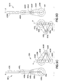
- FIGS. 30A and 30B show a schematic illustration of a transport apparatus in accordance with an exemplary embodiment
- FIGS. 31A-31C show schematic illustrations of a coupling system of a transport apparatus in accordance with an exemplary embodiment
- FIGS. 32A-32D , 33 A- 33 D, 34 A- 34 D, 35 A- 35 D and 36 A- 36 D show schematic illustrations of an exemplary operation of a transport apparatus in accordance with an exemplary embodiment
- FIG. 37 is a graphical representation of the operation of a mechanical motion switch in accordance with an exemplary embodiment
- FIGS. 38A-38E show schematic illustrations of an exemplary operation of a transport apparatus in accordance with an exemplary embodiment
- FIG. 39 is a schematic illustration of a portion of a transport apparatus in accordance with another exemplary embodiment.
- FIGS. 40A-40C is a graphical representation of a mechanical motion switch in accordance with an exemplary embodiment
- FIG. 41 illustrates an exemplary motion profile of a transport apparatus in accordance with an exemplary embodiment
- FIGS. 42A-42D , 43 and 44 show schematic illustrations of an exemplary operation of a transport apparatus in accordance with an exemplary embodiment
- FIGS. 45A-45C is a graphical representation of a mechanical motion switch in accordance with an exemplary embodiment.
- FIGS. 46A-46D show schematic illustrations of an exemplary operation of a transport apparatus in accordance with an exemplary embodiment.
- a substrate transport apparatus with a manipulator having independently movable arms that utilize a mechanical switch mechanism to allow the two or more arms to have combined rotational and independent pick/place motion (e.g. each arm has two or more degrees of freedom with at least one degree of freedom of each arm substantially independent of the degrees of freedom of the other arms) with as few as two independently controllable motors.
- the drive for the two or more arms may be for example integrated into the vacuum transport chamber walls, which allows integration of vacuum system components (vacuum pumps, gauges, and valves) to the bottom of the chamber.
- the shoulders of the arms may be positioned off center (closer to the processing station), resulting in articulated arms that have a SEMI (Semiconductor Equipment and Materials International) reach of the robot, but smaller than conventional arms.
- SEMI semiconductor Equipment and Materials International
- FIGS. 2A-2D there are shown a schematic views of substrate processing apparatus or tools incorporating features of the exemplary embodiments as disclosed further herein.
- a processing apparatus such as for example a semiconductor tool station 1090 is shown in accordance with an exemplary embodiment.
- a semiconductor tool is shown in the drawings, the embodiments described herein can be applied to any tool station or application employing robotic manipulators.
- the tool 1090 is shown as a cluster tool, however the exemplary embodiments may be applied to any suitable tool station such as, for example, a linear tool station such as that shown in FIGS. 2C and 2D and described in U.S. patent application Ser. No. 11/442,511, entitled “Linearly Distributed Semiconductor Workpiece Processing Tool,” filed May 26, 2006, the disclosure of which is incorporated by reference herein in its entirety.
- the tool station 1090 generally includes an atmospheric front end 1000 , a vacuum load lock 1010 and a vacuum back end 1020 .
- the tool station may have any suitable configuration.
- the components of each of the front end 1000 , load lock 1010 and back end 1020 may be connected to a controller 1091 which may be part of any suitable control architecture such as, for example, a clustered architecture control.
- the control system may be a closed loop controller having a master controller, cluster controllers and autonomous remote controllers such as those disclosed in U.S. patent application Ser. No. 11/178,615, entitled “Scalable Motion Control System,” filed Jul. 11, 2005, the disclosure of which is incorporated by reference herein in its entirety.
- any suitable controller and/or control system may be utilized.
- the front end 1000 generally includes load port modules 1005 and a mini-environment 1060 such as for example an equipment front end module (EFEM).
- the load port modules 1005 may be box opener/loader to tool standard (BOLTS) interfaces that conform to SEMI standards E15.1, E47.1, E62, E19.5 or E1.9 for 300 mm load ports, front opening or bottom opening boxes/pods and cassettes.
- the load port modules may be configured as 200 mm wafer interfaces or any other suitable substrate interfaces such as for example larger or smaller wafers or flat panels for flat panel displays.
- two load port modules are shown in FIG. 2A , in alternate embodiments any suitable number of load port modules may be incorporated into the front end 1000 .
- the load port modules 1005 may be configured to receive substrate carriers or cassettes 1050 from an overhead transport system, automatic guided vehicles, person guided vehicles, rail guided vehicles or from any other suitable transport method.
- the load port modules 1005 may interface with the mini-environment 1060 through load ports 1040 .
- the load ports 1040 may allow the passage of substrates between the substrate cassettes 1050 and the mini-environment 1060 .
- the mini-environment 1060 generally includes a transfer robot 1013 as will be described in greater detail below.
- the robot 1013 may be a track mounted robot such as that described in, for example, U.S. Pat. No. 6,002,840, the disclosure of which is incorporated by reference herein in its entirety.
- the mini-environment 1060 may provide a controlled, clean zone for substrate transfer between multiple load port modules.
- the vacuum load lock 1010 may be located between and connected to the mini-environment 1060 and the back end 1020 .
- the load lock 1010 generally includes atmospheric and vacuum slot valves.
- the slot valves may provide the environmental isolation employed to evacuate the load lock after loading a substrate from the atmospheric front end and to maintain the vacuum in the transport chamber when venting the lock with an inert gas such as nitrogen.
- the load lock 1010 may also include an aligner 1011 for aligning a fiducial of the substrate to a desired position for processing.
- the vacuum load lock may be located in any suitable location of the processing apparatus and have any suitable configuration.
- the vacuum back end 1020 generally includes a transport chamber 1025 , one or more processing station(s) 1030 and a transfer robot 1014 .
- the transfer robot 1014 will be described below and may be located within the transport chamber 1025 to transport substrates between the load lock 1010 and the various processing stations 1030 .
- the processing stations 1030 may operate on the substrates through various deposition, etching, or other types of processes to form electrical circuitry or other desired structure on the substrates.
- Typical processes include but are not limited to thin film processes that use a vacuum such as plasma etch or other etching processes, chemical vapor deposition (CVD), plasma vapor deposition (PVD), implantation such as ion implantation, metrology, rapid thermal processing (RTP), dry strip atomic layer deposition (ALD), oxidation/diffusion, forming of nitrides, vacuum lithography, epitaxy (EPI), wire bonder and evaporation or other thin film processes that use vacuum pressures.
- the processing stations 1030 are connected to the transport chamber 1025 to allow substrates to be passed from the transport chamber 1025 to the processing stations 1030 and vice versa.
- FIG. 2C a schematic plan view of a linear substrate processing system 2010 is shown where the tool interface section 2012 is mounted to a transport chamber module 3018 so that the interface section 2012 is facing generally towards (e.g. inwards) but is offset from the longitudinal axis X of the transport chamber 3018 .
- the transport chamber module 3018 may be extended in any suitable direction by attaching other transport chamber modules 3018 A, 3018 I, 3018 J to interfaces 2050 , 2060 , 2070 as described in U.S. patent application Ser. No. 11/442,511, previously incorporated herein by reference.
- Each transport chamber module 3018 , 3019 A, 3018 I, 3018 J includes a substrate transport 2080 as will be described in greater detail below for transporting substrates throughout the processing system 2010 and into and out of, for example, processing modules PM.
- each chamber module may be capable of holding an isolated or controlled atmosphere (e.g. N2, clean air, vacuum).
- FIG. 2D there is shown a schematic elevation view of an exemplary processing tool 410 such as may be taken along longitudinal axis X of the linear transport chamber 416 .
- tool interface section 12 may be representatively connected to the transport chamber 416 .
- interface section 12 may define one end of the tool transport chamber 416 .
- the transport chamber 416 may have another workpiece entry/exit station 412 for example at an opposite end from interface station 12 .
- other entry/exit stations for inserting/removing workpieces from the transport chamber may be provided.
- interface section 12 and entry/exit station 412 may allow loading and unloading of workpieces from the tool.
- workpieces may be loaded into the tool from one end and removed from the other end.
- the transport chamber 416 may have one or more transfer chamber module(s) 18 B, 18 i .
- Each chamber module may be capable of holding an isolated or controlled atmosphere (e.g. N2, clean air, vacuum).
- N2 isolated or controlled atmosphere
- the configuration/arrangement of the transport chamber modules 18 B, 18 i , load lock modules 56 A, 56 B and workpiece stations forming the transport chamber 416 shown in FIG. 2D is merely exemplary, and in alternate embodiments the transport chamber may have more or fewer modules disposed in any desired modular arrangement.
- station 412 may be a load lock.
- a load lock module may be located between the end entry/exit station (similar to station 412 ) or the adjoining transport chamber module (similar to module 18 i ) may be configured to operate as a load lock.
- transport chamber modules 18 B, 18 i have one or more corresponding transport apparatus 26 B, 26 i located therein.
- the transport apparatus 26 B, 26 i of the respective transport chamber modules 18 B, 18 i may cooperate to provide the linearly distributed workpiece transport system 420 in the transport chamber.
- the transport apparatus 26 B may have a general SCARA arm configuration as will be further defined herein (though in alternate embodiments the transport arms may have any other desired arrangement).
- the arms of the transport apparatus 26 B may be arranged to provide what may be referred to as fast swap arrangement allowing the transport to quickly swap wafers from a pick/place location as will also be described in further detail below.
- the transport arm 26 B may have a suitable drive section for providing each arm with three (3) (e.g. independent rotation about shoulder and elbow joints with Z axis motion) degrees of freedom from a simplified drive system compared to conventional drive systems.
- the modules 56 A, 56 , 30 i may be located interstitially between transfer chamber modules 18 B, 18 i and may define suitable processing modules, load lock(s), buffer station(s), metrology station(s) or any other desired station(s).
- interstitial modules such as load locks 56 A, 56 and workpiece station 30 i
- the interstitial modules may each have stationary workpiece supports/shelves 56 S, 56 S 1 , 56 S 2 , 30 S 1 , 30 S 2 that may cooperate with the transport arms to effect transport or workpieces through the length of the transport chamber along linear axis X of the transport chamber.
- workpiece(s) may be loaded into the transport chamber 416 by interface section 12 .
- the workpiece(s) may be positioned on the support(s) of load lock module 56 A with the transport arm 15 of the interface section.
- the workpiece(s), in load lock module 56 A may be moved between load lock module 56 A and load lock module 56 by the transport arm 26 B in module 18 B, and in a similar and consecutive manner between load lock 56 and workpiece station 30 i with arm 26 i (in module 18 i ) and between station 30 i and station 412 with arm 26 i in module 18 i .
- This process may be reversed in whole or in part to move the workpiece(s) in the opposite direction.
- workpieces may be moved in any direction along axis X and to any position along the transport chamber and may be loaded to and unloaded from any desired module (processing or otherwise) communicating with the transport chamber.
- interstitial transport chamber modules with static workpiece supports or shelves may not be provided between transport chamber modules 18 B, 18 i .
- transport arms of adjoining transport chamber modules may pass off workpieces directly from end effector or one transport arm to end effector of another transport arm to move the workpiece through the transport chamber.
- the processing station modules may operate on the substrates through various deposition, etching, or other types of processes to form electrical circuitry or other desired structure on the substrates.
- the processing station modules are connected to the transport chamber modules to allow substrates to be passed from the transport chamber to the processing stations and vice versa.
- a suitable example of a processing tool with similar general features to the processing apparatus depicted in FIG. 2D is described in U.S.
- a substrate transport apparatus 300 having for example dual same side SCARA arms and incorporating a mechanical switch mechanism (see also FIGS. 3A-B ).
- the transport chamber 30 may be generally similar to chamber modules 18 B, 18 i shown in FIG. 2 .
- the transport apparatus may include independently articulated arms A and B, and is located within a transport chamber 30 .
- the dual same side SCARA arms are indicated as Arm A 41 and Arm B 43 with the transport chamber not shown.
- the substrate for transport is indicated by S and is positioned on a forked shaped end effector 32 .
- the end effector may be of an alternative shape including, but not limited to, paddle shaped.
- the arm(s) may have any number of end effectors.
- the substrate S is representative and may be of any size, and shape such as a 200 mm, 300 mm, 450 mm or larger semiconductor wafer, a reticle or pellicle or panel for flat screen displays.
- each arm may have for example a SCARA arrangement, though in alternate embodiments the transport arms may have any other desired arrangement.
- the transport arms are generally similar, though in alternate embodiments the arms may be different.
- the end effector 32 is pivotally connected at wrist joint 34 , to a forearm 36 for each Arm A 41 and B 43 .
- the forearm 36 is pivotally connected at an elbow joint 38 , to an upper arm 40 for each of Arm A 41 and Arm B 43 .
- the upper arm 40 for Arm A 41 and B 43 , are in turn mounted to a common base rotor 42 for the T 2 motor 44 via the arm shoulder joint 46 .
- FIG. 4D is a schematic partial elevation view of the transport chamber 30 and drive section of transport apparatus 300 .
- the T 1 , T 2 motors may be any suitable type of motors and may be incorporated within the wall structure of the chamber 30 .
- the T 1 , T 2 motors may be brushless DC motors (though any other suitable motors may be used), with stator coils integrated into walls and isolated from the internal atmosphere of the chamber 30 .
- the drive may be a bearing drive system located at least partially below the chamber 30 as shown in FIG. 4E and as will be described in greater detail below.
- the drive may be a combination of, for example, the bearing drive system and the drive located in the chamber walls.
- the drive may be any combination of the drive systems disclosed herein and any suitable conventional drive system.
- the motors may be housed in a common section 302 that is capable of Z axis motion, as shown in FIG. 4D , hence providing the arms with Z motion.
- a suitable flexible seal SC (such as a bellows seals may connect the drive belt to the adjoining wall structure to maintain the isolatable atmosphere in the transport chamber module.
- the drive section may be operably connected to a suitable Z-drive T 3 illustrated substantially in FIG. 4D .
- the Z-drive may be of any suitable type, such as including windings (not shown) in the stator capable of moving the rotors 42 , 50 R in the Z direction.
- the Z-drive windings may also provide, in addition to Z location control, Z-stability for the motor rotors and arms holding the rotors and arms in a desired Z-location.
- the motors may be self bearing in both radial and Z-directions, or may have passive radial and Z bearing systems such as permanent magnets or mechanical bearings or a combination thereof for Z and radial bearing.
- the Z-drive may include a Z-drive motor powering a lead screw connected to the section 302 to effect Z-motion of the transport arms.
- the shoulder joint 46 of the arms 41 , 43 is coaxial, the respective upper arms 40 A, 40 B pivoting about a common shaft 24 that may be offset from the rotor axis of rotation 22 .
- the arms may be mounted with offset shoulder joints, each rotating about a corresponding axis of rotation that are substantially parallel to each other.
- the motor rotors 42 , 50 R are shown as being located on one side, such as in the bottom wall 30 L, of the chamber 30 for example purposes, though in alternate embodiments the rotors may be disposed in one or more of the transport chamber walls, such as one rotor on top (above the transport arms) and one on the bottom (below the arms).
- the rotors may have a generally hollow ring structure, for reduced weight.
- the rotors may have any suitable shape and configuration.
- a crank link 48 connects the upper arm 40 A, B for each arm A 41 and B 43 to a revolute joint 52 on the rotor 50 R of T 1 motor 50 .
- the two crank links share a common convergent or pivot (e.g. shaft) 52 on the rotor 50 R of motor T 1 .
- the locations of the revolute joints 20 A, 20 B of each link 48 A, 48 B to the respective upper arms 40 A, 40 B are for example on substantially opposite sides of the X axis, along which the end effectors 32 of each arm is extended/retracted.
- the T 1 motor 50 may be rotated while the T 2 motor 44 is stationery.
- the T 1 motor When the T 1 motor is rotated in one direction, one arm extends or retracts while the second arm practically does not move due to what may be called a mechanical switch or lost motion system that develops motion of one arm from another, generated by a common motor without physically decoupling the arms from the motor (see also FIGS. 3A-B ).
- FIG. 4C depicts Arm A 41 in an extended position beyond the confines of the transport chamber 30 while Arm B is retracted within the transport chamber 30 .
- This movement of Arm A 41 allows for a substrate S to be picked up and placed in a storage chamber or processing station.
- both the T 2 motor 44 and the T 1 motor 50 are rotated to the same degree.
- the T 1 motor 50 and T 2 motor 44 have independent drive shafts which necessitates that the center of rotation of T 1 is offset from T 2 .
- FIGS. 3A-B depict the principle of operation of the mechanical switch mechanism 10 for arm motion disclosed herein when used in a same side dual arm configuration.
- FIG. 3A-B depict the mechanical switch mechanism 10 of the same side dual SCARA arm configuration shown in FIGS. 4A-4D .
- the lines and connections thereof to the respective arms 40 A, 40 B and common motor T 1 , rotor 50 R are substantially mirror images of each other, and may be represented as shown in FIGS. 3A-3B for clarity to illustrate its operation.
- mechanical switch mechanism 10 may include upper arms 40 A, 40 B, in the exemplary embodiment sharing common revolute joint 24 , but shown as circular members (with diameter 14 ) on opposing revolute joints 24 , 24 ′, T 1 motor rotor 50 R, shown as opposing circular members with diameters 12 ) on (common) axis of rotation 22 .
- These members may be linked together with crank links 48 A, 48 B at revolute joints 18 , 18 ′ joints 20 A, 20 B (to respective upper arms) located on each side of the links 48 A, 48 B.
- Non-limiting exemplary bearings 18 , 20 include needle type, ball bearing type or bushing type.
- each arm 41 , 43 may have a corresponding crank link 48 A, 48 B coupling the circle (T 1 ) representing the motor rotor 50 R, 50 R′ with the smaller circle (T 2 ) representing in the example the upper arms 40 A, 40 B of the corresponding arms.
- the link coupling motor and articulated arm may be joined to any other desired section of the arm.
- the resultant motions of the arms A, B ( 41 , 43 ) effected by motor T 1 ( 50 ) via the mechanical switch 10 are substantially depicted in FIG. 3B by way of example, when T 1 rotates between 0 and ⁇ 135 degrees (counterclockwise), Arm A ( 41 ) is changing extension angle or rotating (about shoulder 24 ). In contrast, Arm B ( 43 ) is practically not moving. However, when T 1 rotates between 0 and +135 degrees (clockwise), Arm B is changing extension angle or rotating (about shoulder 24 ) and Arm A is practically not moving.
- the relative motions illustrating the operation of the switch in the exemplary embodiment are also depicted graphically in the graph of FIG.
- the two crank links 48 A, 48 B may be attached opposite of the axis of symmetry so when T 1 rotates in one direction, one link and arm combination are substantially locked, causing arm rotation with T 1 and the other link and arm combination is substantially released or free thus not undergoing movement with T 1 .
- the previously locked arm releases to rotate with T 1 while substantially the previously free arm substantially locks to rotate with T 1 .
- This allows for independent extension of the two arms (depending on the direction and degree of rotation) from but one motor T 1 .
- the two arms rotate relative to for example transport chamber 30 (e.g. about center of rotation 22 ), as a unit.
- the T 1 , T 2 motors 42 , 50 may be rotary motors (such as brushless DC motors as noted before) that are coupled to the respective arms A, B ( 41 , 43 ) via what may be referred to as a shaft less drive coupling system.
- the stators 50 S, 44 S of the T 1 , T 2 motors may be generally linearly distributed such as in a generally arcuate manner substantially around and proximate the periphery of the transport chamber 30 .
- the diameter of the T 1 , T 2 motors may be maximized relative to the space envelope of the transport chamber, which as may be realized may be minimized to the space envelope circumscribing the clearances for the motions of the arms A, B and wafers on the one or more end effector(s) of the arms.
- the T 1 motor for example, operates to impart a force on the arms A, B that is eccentric to the shoulder axis of rotation (e.g. revolute joint 24 ) hence, by way of example the T 1 motor 50 output imparts a leverage force in the arms A, B that pivots the arms about a fulcrum defined for example by shoulder joint 24 .
- the coupling system between arms and motor 50 that includes the previously described mechanical switch 10 , causes a resultant force to be applied by motor 50 to the arms that is eccentric to shoulder axis of rotation.
- the motors and couplings delivering power from the motors to the arms may have any other suitable arrangement.
- FIGS. 5A-D the extensional movement of Arm A 41 is depicted in four different extensional positions for the substrate transport apparatus 300 with dual same side SCARA arms incorporating the mechanical switch mechanism disclosed herein.
- the two crank links 48 connecting the arm shoulder joints 46 on the T 2 motor mounting plate 44 to the T 1 motor 50 substantially converge at revolute joint 62 (similar to joint 52 in FIG. 4D ) along the circumference of T 1 50 as noted before, in alternate embodiments, the links may be joined to the T 1 motor rotor at offset revolute joints.
- crank links 48 A, 48 B also rotate along the circumference of T 1 from position 62 to point B 64 in FIG. 5 B, which in turn causes Arm A 41 to extend outward toward the right while Arm B 43 remains essentially fixed in the retracted position.
- the crank links 48 further rotate along the circumference of T 1 to point C 66 in FIG. 5C , which in turn causes Arm A 41 to further extend outward toward the right while Arm B 43 still remains essentially fixed in the retracted position.
- the crank links 48 further rotate along the circumference of T 1 to point D 68 in FIG.
- the extensional movement of Arm B 43 is depicted in three different extensional positions for the substrate transport apparatus 300 with dual same side SCARA arms incorporating the mechanical switch mechanism disclosed herein.
- the two crank links 48 connecting the arm shoulder joints 46 (supported on the T 2 motor rotor 44 ) to the T 1 motor by way of example 50 are positioned for example at point E 72 along the circumference of T 1 motor 50 .
- the crank links 48 also rotate along the circumference of T 1 to point F 74 in FIG. 6B , which in turn causes Arm B 43 to extend outward toward the right while Arm A 41 remains essentially fixed in the retracted position.
- FIGS. 7A-E the rotational movement of Arm A 41 and Arm B 43 are depicted in five different rotational positions for the substrate transport apparatus 300
- the end effector(s) 32 are pointing along the positive x-axis.
- Arms A and B, 41 , 43 will correspondingly rotate as a unit about axis of rotation 22 in the same direction along the continuum shown in FIGS. 7B , 7 C, 7 D and 7 E.
- FIGS. 8A-C the extension/retraction movement of Arm B 43 in the exemplary embodiment is depicted in three different exemplary positions alongside with the corresponding positions of arm A 41 .
- arm B is in an extended position and in FIG. 8C arm 8 is retracted.
- the revolute joint for the two crank links 48 connecting the arm shoulders 42 on the T 2 motor mounting plate 44 to the T 1 motor 50 is located at point H 82 along the circumference of T 1 motor 50 .
- T 1 motor 50 is rotated, for example in the clockwise direction, the crank links 48 also rotate along the circumference of T 1 to point 184 in FIG.
- FIGS. 5A-D , 6 A-C, 7 A-E and 8 A-C enables but two motors (T 1 and T 2 ) to effectuate both substantially independent extension/retraction of each arm and rotation of the dual same side SCARA arms via the mechanical switch mechanism described herein.
- standard dual same side SCARA arms require three (3) motors to effectuate the extension/retraction and rotation of the two arms.
- the mechanical switch mechanism disclosed herein allows for the elimination of one (1) motor and the corresponding cost savings and space reduction benefits.
- FIGS. 9A-C illustrate an exemplary synchro system for the dual same side SCARA arms or arm assemblies in three different extensional positions in accordance with an exemplary embodiment that will be described below.
- the substrate transport apparatus 300 may include a drive section (T 1 and T 2 motors not shown), a coupling system between the drive section, and arms or arm assemblies 491 L, 491 R.
- the substrate transport 300 is shown having two SCARA arm assemblies, but in alternate embodiments the substrate transport may have any suitable configuration with any suitable number and/or configuration of arm assemblies.
- the drive section and coupling system as previously described in FIGS. 3-8 includes or defines what is referred to here as a mechanical switch mechanism that enables two drive motors (T 1 and T 2 ) of the drive section to effect extension/retraction and rotation of more than one SCARA arm substantially independent of each other.
- the T 1 and T 2 motors may be constructed from two stacked rings (rotors) coupled with stator windings integrated in the transport chambers walls, possibly external to the vacuum, which may allow mounting of the vacuum system components to the bottom of the transport chamber.
- positioning of the upper arm shoulder off center of the transport chamber provides SEMI reach with significantly smaller arms than with respect to prior art SCARA arm design.
- the arms 491 L, 491 R are substantially similar to arms A, B 41 , 43 of the transport apparatus 300 and include an upper arm member 490 L, 490 R, a forearm member 460 L, 460 R and an end effector 430 L, 430 R connected to each other through respective revolute joints 492 , 493 , 494 , 495 .
- the arms may have more or fewer articulations.
- the upper arms 490 L, 490 R pivot about revolute joints 402 , 401 (e.g. shoulder joint 24 , see FIG. 4A-4D ).
- the proximate ends of the upper arms 490 L, 490 R are pivotally joined to the links 422 L, 422 R of the coupling system through revolute joints 404 , 406 as previously described.
- the distal ends of the upper arms 490 L, 490 R may for example be pivotally joined to respective proximate ends of the forearms 460 L, 460 R at revolute joints 492 , 493 .
- the distal ends of the forearms 460 L, 460 R may be pivotally joined to the end effectors 460 L, 460 R at revolute joints 494 , 495 .
- the end effectors 460 L, 460 R may have a longitudinal axis running from the front of the end effector to the back of the end effector.
- the longitudinal axis of the end effectors may be aligned with a path of extension and retraction P of the arms as previously described in FIGS. 3-8 .
- the arms may have any desired configuration relative to the axis of extension/retraction P.
- the links 48 A, 48 B (See FIGS. 3-8 ) of the coupling system may be incorporated into or are part of the upper arms 490 L, 490 R respectively so that links 423 L, 423 R form a portion or extension of their respective arm as previously described.
- the arms may be configured to include the upper arm portions 423 L, 423 R in any suitable manner.
- the revolute joints 402 , 401 (mounted to motor T 2 ) may be the pivot points of the upper arms 490 L, 490 R respectively.
- the upper arm portions 423 L, 423 R may be connected to a pulley or disk that is mounted to the upper arm so that as the respective disk rotates around point 402 or 401 thereby rotating a respective upper arm 491 L, 491 R.
- the upper arm portions may depend from any portion of the arm for imparting torque to the upper arm.
- the relationship or orientation of the upper arm portions 423 L, 423 R to the rest of the upper arm as shown in FIGS. 9A-C is merely exemplary and the upper arm portions 423 L, 423 R may have any suitable relationship/orientation to the upper arm.
- the arms 491 L, 491 R may also include a belt and pulley system for driving the forearm.
- pulleys 435 L, 435 R may be coupled to a (stationary) fixture or hub at joints 402 , 401 (for example fixed to post 24 ; see FIG. 4D ) so that as the upper arms rotate, their respective pulleys 435 L, 435 R remain stationary relative to the apparatus frame (e.g. upper arm motion effects relative movement between upper arm and corresponding pulley).
- a second (idler) pulley 445 L, 445 R may be coupled to the forearms 460 L, 460 R about joints 492 , 493 .
- the pulleys 435 L, 445 L and 435 R, 445 R may be connected by any suitable belt or bands 440 L, 440 R so that as the upper arms rotate 490 L, 490 R, relative motion with pulleys 435 L, 435 R causes the pulleys 445 L, 445 R to be drivingly rotated via the belts.
- the pulleys may be connected by one or more metal bands that may be pinned or otherwise fixed to the pulleys.
- any suitable flexible band may connect the pulleys.
- the pulleys may be connected in any suitable manner or any other suitable transmission system may be used.
- the pulleys 435 L, 435 R, 445 L, 445 R may be configured so that the movement of the arm members is constrained so that rotation of the upper arms 490 L, 490 R about joints 402 , 401 produces desired rotation of a respective one of the forearms 460 L, 460 R in the opposite direction.
- the ratio of the radii for pulleys 450 L, 450 R to pulleys 445 L, 445 R may be a 2:1 ratio.
- a second belt and pulley arrangement including pulleys 450 L, 450 R, 465 L, 465 R and belts 455 L, 455 R may be provided to drive the end effectors 430 L, 430 R so that the radial orientation or longitudinal axis of the end effectors 430 L, 430 R along the common path of travel P is maintained as the arms 491 L, 491 R are extended and retracted.
- the pulleys 450 L, 450 R may be coupled to their respective upper arm 490 L, 490 R about joints 492 , 493 and the pulleys 465 L, 465 R may be coupled to their respective end effectors 430 L, 430 R about joints 494 , 495 .
- the ratio of pulleys 450 L, 450 R to pulleys 465 L, 465 R may be a 1:2 ratio.
- pulleys 450 L, 450 R in the exemplary embodiment are mounted in line with a respective one of the pulleys 445 L, 445 R about joints 492 , 493 so that when the pulleys 445 L, 445 R are rotated with the forearms 460 L, 460 R the pulleys 450 L, 450 R remain stationary with respect to their respective upper arms 490 L, 490 R.
- Any suitable belt 455 L, 455 R may connect a respective pair of the pulleys so that as the forearms 460 L, 460 R are rotated the pulleys 465 L, 465 R are drivingly rotated.
- the pulleys may be connected by one or more metal bands that may be pinned or otherwise fixed to the pulleys.
- any suitable flexible band may connect the pulleys.
- the pulleys may be connected in any suitable manner.
- the end effectors 430 L, 430 R may be coupled to a respective forearm at revolute joint 494 , 495 .
- the end effectors 430 L, 430 R may be drivingly coupled to a respective one of the pulleys 465 L, 465 R so that as the arms are extended or retracted the end effectors 430 L, 430 R stay longitudinally aligned with the common path of travel P as can be seen in FIGS. 9B , 9 C.
- the belt and pulley systems described herein may be housed within the arm assemblies 491 L, 491 R so that any particles generated may be contained within the arm assemblies.
- a suitable ventilation/vacuum system may also be employed within the arm assemblies to further prevent particles from contaminating the substrates.
- the synchronization systems may be located outside of the arm assemblies. In other alternate embodiments, the synchronization systems may be in any suitable location.
- the substrate transport apparatus 300 is at its initial or neutral position with both arms 491 L, 491 R in a retracted position.
- the coupling system and a portion of the arms may be located within a housing suitably configured to prevent particles generated by moving parts of the substrate transport from contaminating the substrates.
- a housing suitably configured to prevent particles generated by moving parts of the substrate transport from contaminating the substrates.
- slots may be provided in the housing for the arms to pass where any openings between the slots and the arms are sealed with a flexible seal.
- the housing may have any suitable configuration to prevent substrate contamination from particulates that may be generated from moving parts of the transport.
- the coupling system may not be within a housing.
- arm 491 L is in the extended position while arm 491 R is in its retracted position.
- arm 491 R is in the extended position while arm 491 L is in its retracted position. The extension and retraction of arms 491 L, 491 R are effectuated using the drive and mechanical switch coupling system previously described in FIGS. 3-8 .
- rotation of the upper arm 490 L causes stationary pulley 435 L to drive pulley 445 L via belt 440 L so that as the arm is extended the forearm 430 L is rotated by substantially an equal amount in the opposite direction about revolute joint 492 .
- Rotation of the forearm 490 L in turn causes pulley 450 L to drive pulley 465 L via belt 455 L so that the end effector rotates about point 494 .
- Rotation of the end effector about point 494 is such that the radial orientation or longitudinal axis of the end effector 430 L is maintained along the common path of travel P as the arm 491 L is extended and retracted.
- the rotation of the forearm 430 L is slaved to the rotation of the upper arm 490 L about point 492 and the rotation of the end effector 430 L is slaved to the rotation of the forearm 460 L about point 494 .
- the arm 491 L is extended radially while the arm 491 R remains substantially stationary in its retracted position. Retraction of the arm 491 L occurs in a substantially opposite manner.
- Rotation of the upper arm 490 R causes stationary pulley 435 R to drive pulley 445 R via belt 440 R so that as the arm is extended the forearm 460 R is rotated an equal amount in the opposite direction about revolute joint 493 .
- Rotation of the forearm 460 R in turn causes pulley 450 R to drive pulley 465 R via belt 455 R so that the end effector 430 R rotates about point 495 .
- Rotation of the end effector 430 R about point 495 is such that the radial orientation or longitudinal axis of the end effector 430 R is maintained along the common path of travel P as the arm 491 R is extended and retracted.
- the rotation of the forearm 460 R is slaved to the rotation of the upper arm 490 R about point 493 and the rotation of the end effector 430 R is slaved to the rotation of the forearm 460 R about point 495 .
- the arm 491 R is extended radially while the arm 491 L remains substantially stationary in its retracted position. Retraction of the arm 491 R occurs in a substantially opposite manner.
- the end effectors 430 L, 430 R may travel along a common path of travel P, the end effectors may be configured in such a way so as to be in different planes along the path of travel P.
- the arms 491 L, 491 R may be configured to be at different heights so that the end effectors can travel along the common path P.
- the transport may have any suitable configuration for allowing multiple end effectors to travel along a common path of travel.
- the end effectors may travel along different paths that may be generally parallel or angled relative to each other. The paths may be located in the same plane.
- the illustrated motions of the linkages of the coupling system are merely exemplary and in alternate embodiments the linkages may be arranged to provide and undergo any desired range of motion switching from driving the arms independently of each other.
- the substrate transport apparatus may be powered from a drive section with a coaxial drive shaft assembly.
- the drive system 100 may have coaxial inner and outer drive shafts 101 , 102 driven by motors 104 , 103 respectively.
- the motors 103 , 104 may each have a rotor 103 R, 104 R attached to their respective drive shaft 102 , 101 and a stator 103 S, 104 S for driving the rotor, the stator 103 S, 104 S being stationarily connected to a housing 100 H of the drive system 100 .
- the drive system may not be coaxial.
- the housing 100 H of the drive system 100 may be coupled to chamber 30 ( FIG. 4A ) so that at least part of the drive system housing 100 H forms part of the interior of the chamber 30 .
- the rotors 103 R, 104 R may be located within the atmosphere of the chamber 30 while the stators 103 S, 104 S are suitably isolated from the chamber atmosphere.
- Suitable examples of the coaxial drive 100 may be substantially similar to that described in U.S. Pat. Nos. 5,720,590, 5,899,658, 5,813,823, and 6,485,250 and/or Patent Publication Number 2003/0223853, which are incorporated herein by reference in their entirety.
- any suitable drive section may be employed such as for example a non-coaxial drive assembly or a magnetic drive assembly.
- the drive section may be housed within a housing of the substrate transport to prevent contamination or damage to the substrates from any particles that may been generated from the moving parts of the drive section.
- the coaxial drive assembly may have an inner and outer drive shaft 101 , 102 .
- the outer drive shaft 102 may be connected to a housing of the substrate transport so that when the outer drive shaft 102 is rotated the arms 491 L, 491 R of the substrate transport apparatus are rotated about an axis of rotation of the outer drive shaft 102 .
- the inner drive shaft 101 may be connected to the coupling system at rotation point 42 so that when the inner drive shaft 101 is rotated the coupling system will rotate or pivot about an axis of rotation (i.e. rotation point 42 ) of the inner drive shaft 101 .
- the outer drive shaft 102 may be connected to the motor rotor (generally analogous to the T 1 motor powering arm extension/retraction) of the substrate transport apparatus so that when the outer drive shaft is rotated the dual arms may be independently extended/retracted in a similar manner to that previously described and shown in FIGS. 3-8 .
- the inner drive shaft 101 of the coaxial drive assembly may also rotate in the same direction and at substantially the same speed as the outer drive shaft to keep the arms of the transport apparatus from extending or retracting as the arms of the substrate transport apparatus are rotated substantially as a unit.
- the inner drive shaft 101 may be connected to a hub assembly (somewhat analogous to motor T 2 ) via a coupling system at rotation point 42 so that when the inner drive shaft 101 is rotated the coupling system will rotate or pivot about an axis of rotation (i.e. rotation point 42 ) of the inner drive shaft.
- FIGS. 10A-B a substrate transport apparatus 310 with dual same side SCARA arms incorporating the mechanical switch mechanism with a coaxial drive assembly is depicted.
- the transport apparatus with a coaxial drive assembly including Arms A 141 and Arm B 143 are located within a transport chamber 130 .
- the dual same side SCARA arms are indicated as Arm A 141 and Arm B (only a portion of which is shown for clarity) with the transport chamber (also not shown).
- the arms and transport chamber are substantially similar to arms A, B in transport chamber 30 described previously. Similar features are similarly numbered.
- the substrate for the transport 310 is not shown, but would be positioned on an end effector 132 .
- the end effector 132 is shown as having a forked shape but in alternate embodiments the end effector may be of an alternative shape including, but not limited to, paddle shaped.
- the end effector 132 is pivotally connected to a wrist or pivot joint 134 , which in turn is connected to a forearm 136 for each Arm A 141 and B 143 .
- the forearm 136 is pivotally connected to an elbow or pivot joint 138 , which in turn is connected to an upper arm 140 for each of Arm A 141 and Arm B 143 .
- the upper arm 140 for Arm A 141 and B 143 are in turn mounted to a common base or mounting plate 142 for the T 1 and T 2 motors 150 , 144 via their respective arm shoulder joints 146 .
- the center of the coaxial drive assembly for the T 1 and T 2 motors is also the center of the common base or mounting plate 142 .
- an extension arm 147 extends radially outward from the coaxial drive shaft for T 1 motor 150 .
- a crank link 148 connects the arm shoulder joints 146 for each of Arm A 141 and B 143 to a revolute joint 152 on the extension arm 147 or motor T 1 .
- the two crank links 148 may share a common pivot point 152 offset from the center of the coaxial drive assembly 142 though in alternate embodiments the links may be joined to motor T 1 at offset revolute joints.
- FIGS. 10A-B in order to effectuate extension of Arm A 141 or Arm B 143 for pick and place of a substrate S on the end effector 132 , the T 1 motor 150 is rotated while the T 2 motor 144 is stationery. When the T 1 motor is rotated in one direction, one arm extends or retracts while the second arm practically does not move in a similar manner to that previously described in FIGS. 3A-B .
- FIG. 10A depicts Arm A 141 in an extended position for example beyond the confines of the transport chamber 130 while Arm B may be retracted within the transport chamber 130 . This movement of Arm A 141 allows for a substrate S to be picked up and placed in a storage chamber or processing station.
- both the T 2 motor 144 and the T 1 motor 150 are rotated to the same degree. This maintains the crank links 148 for Arm A 141 and Arm B stationary relative to one another so as to not exert a torque on one of the two arms to effectuate extension or retraction.
- T 1 and the arm shoulder joints 146 rotate about a common axis of rotation.
- FIGS. 11A-D the extensional movement of Arm A 141 is depicted in four different extensional positions for the substrate transport apparatus 310 with dual same side SCARA arms incorporating the mechanical switch mechanism with a coaxial drive assembly disclosed herein.
- the two crank links 148 and extension arm 147 connecting the arm shoulder joints 146 on the T 2 motor mounting plate 144 to the T 1 motor 150 converge at point A 162 along the circumference of T 1 150 .
- the crank links 148 and extension arm 147 also rotate along the circumference of T 1 to point B 164 in FIG.
- a bisymmetric SCARA arm drive arrangement as can be seen in FIGS. 12A-12B and 13 A- 13 C may be utilized in place of a dual same side SCARA arm drive arrangement as was previously described in FIGS. 3-11 .
- a bisymmetric SCARA arm drive arrangement two or more arms of the substrate transport apparatus may be arranged and/or oriented in different or opposite directions relative to each other.
- the substrate transport apparatus with a bisymmetric SCARA arm design utilizing a mechanical switch mechanism similar to that previously described allows for arm A and arm B to be positioned in the same plane and to correspondingly have a smaller envelope of motion.
- T 1 and T 2 motors may again be constructed from two stacked rings (rotors) coupled with stator windings integrated in the transport chambers walls, possibly external to the vacuum, which may allow mounting of the vacuum system components to the bottom of the transport chamber.
- positioning of the upper arm shoulder off center of the transport chamber provides SEMI reach with significantly smaller arms than with respect to prior art SCARA arm design.
- each motor such as T 1 motor 250 and T 2 motor 244 , has a link 247 , 248 pivotally connected thereto (e.g. link 248 to T 1 motor and link 247 to T 2 motor).
- crank link 247 connects the Arm B 241 elbow joint 238 to T 2 244 .
- the other crank link 248 connects the Arm A 244 elbow joint 238 to T 1 250 .
- T 1 and T 2 250 , 244 may be motors substantially similar to that described before shown in FIG. 4D .
- each SCARA arm is joined, via a corresponding revolute joint 246 A, 246 B at for example the shoulder joint to a respective rotor of the T 1 , T 2 motors. As seen best in FIG.
- revolute joint 246 A (of arm A) is fixed to the T 2 motor rotor, and the link 248 joined at one end to upper arm 240 A (of arm A) is joined to the T 1 motor rotor.
- the shoulder joint 246 B of arm B is fixed to the T 1 motor rotor, and the link 247 is pinned at the T 2 motor rotor.
- the dual bisymmetric SCARA arms are indicated as Arm A 241 and Arm B 243 with the transport chamber not shown.
- the substrate for the transport 320 is indicated by S and is positioned on end effector 232 .
- the end effector may be of any suitable shape including, but not limited to, fork and paddle shaped.
- the end effector 232 A, B is pivotally connected to a wrist joint 234 A, B, which in turn is connected to a forearm 236 A, B for each Arm A 241 and B 243 .
- the forearm 236 is pivotally connected to an elbow joint 238 , which in turn is connected to an upper arm 240 for each of Arm A 241 and Arm B 243 .
- the upper arm(s) 240 A, B for Arm A 241 and B 243 are in turn respectively mounted to a corresponding rotor(s) 244 , 250 for the T 1 , T 2 motor(s) via respective arm shoulder joint(s) 246 A, B.
- one crank link 247 connects the Arm B 243 elbow joint 238 to T 2 244 .
- the other crank link 248 connects the Arm A 241 elbow joint 238 to T 1 250 .
- the T 1 motor 250 is rotated while the T 2 motor 244 is stationery.
- this type of switch type mechanism by way of example when T 1 250 rotates in one direction and when T 2 244 is stationary, it effectuates extension and retraction of one arm. More particularly, when either the T 1 or T 2 motors are rotated causing relative movement between T 2 and T 1 motors in one direction, one arm extends or retracts while the second arm practically does not move due to the mechanical switch mechanism.
- the relative movement of T 2 244 and T 1 250 motor is in the opposite direction, it effectuates extension of the other arm positioned opposite to the first arm.
- the second arm when the T 2 motor is rotated in the opposite direction, the second arm extends or retracts while the first arm practically does not move due to the principle of operation of the mechanical switch mechanism.
- the respective revolute joints e.g. shoulder joint 246 A, B and link pivots
- the shoulder joint and link pivots on each rotor may be offset from each other.
- both the T 2 motor 244 and the T 1 motor 250 are rotated to the same degree.
- the principle of operation of the mechanical switch mechanism is depicted graphically, which plots the extension angle of Arms A and B versus the difference in rotation angle between T 1 and T 2 .
- the two crank links 247 , 248 are attached opposite of the axis of symmetry so when T 1 rotates in one direction, one arm physically locks and the other arm is free to rotate with T 1 .
- FIG. 13A-C the substrate transport apparatus 320 with dual bisymmetric SCARA arms incorporating the mechanical switch mechanism of FIGS. 12A-B is depicted.
- the transport apparatus including Arms A and B is located within a transport chamber 230 .
- the dual bisymmetric SCARA arms are indicated as Arm A 241 and Arm B 243 with the transport chamber not shown.
- Arm B 243 is depicted in three different extensional positions for the substrate transport apparatus 320 with dual bisymmetric SCARA arms incorporating the mechanical switch mechanism disclosed herein.
- arm B 243 is shown slightly extended while arm A 241 is shown fully retracted with the crank link 248 effectuating arm B 243 movement at point A 262 along T 1 250 .
- crank link 248 effectuating arm B 243 movement at point A 262 along T 1 250 .
- FIGS. 15A-C the extensional movement of Arm A 241 is depicted in three different extensional positions for the substrate transport apparatus 320 with dual bisymmetric SCARA arms incorporating the mechanical switch mechanism disclosed herein.
- the transport apparatus shown in FIGS. 15A-15C may be rotated 180 degrees from the orientation of the apparatus illustrated in FIGS. 14A-14C (such as for example when effecting a swap from a substrate holding station).
- arm A 241 is shown slightly extended while arm B 243 is shown fully retracted with the crank link 247 effectuating arm A 241 movement at point D 272 along T 1 250 .
- FIG. 15A arm A 241 is shown slightly extended while arm B 243 is shown fully retracted with the crank link 247 effectuating arm A 241 movement at point D 272 along T 1 250 .
- crank link 247 connected to the T 2 rotor 244 also moves with the circumference of the T 2 244 rotor, which in turn causes Arm A 241 to extend outward toward the right while Arm B 243 remains essentially fixed in the retracted position (the crank link 248 being released).
- the crank link 247 effectuating arm A 241 movement moves from point D 272 to point E 274 along T 2 244 .
- crank link 247 connected to the T 2 rotor 244 further rotates along the circumference of T 2 244 , which in turn causes Arm A 241 to further extend outward toward the right while Arm B 243 still remains essentially fixed in the retracted position.
- the crank link 247 effectuating arm A 241 movement moves from point E 274 to point F 276 along T 2 244 .
- the direction of T 2 244 is reversed along points F 276 , E 274 , and D 272 .
- FIGS. 16A-D the rotational movement of Arm A 241 and Arm B 243 are depicted in four different rotational positions for the substrate transport apparatus 320 with dual bisymmetric SCARA arms incorporating the mechanical switch mechanism disclosed herein.
- the two arms 241 , 243 are pointing in opposite directions along P.
- Arms A and B, 241 , 243 will correspondingly rotate in, for example (depending on which direction T 1 and T 2 are rotated), the counterclockwise direction along the continuum shown in FIGS. 16B , 16 C, and 16 D.
- Arms A and B, 241 , 243 will correspondingly rotate in, for example, the clockwise direction in a manner substantially opposite the counterclockwise rotation shown in FIGS. 16B , 16 C, and 16 D (i.e. the sequence of rotation would be from FIGS. 16D to 16A rather than from 16 A to 16 D).
- a coaxial drive shaft assembly may be used for coupling the T 1 and T 2 motors to the SCARA arms and mechanical switch.
- the center of rotation of T 1 and T 2 may be substantially the same.
- the coaxial drive may be substantially similar to that described above with respect to FIG. 4E .
- the outer drive shaft 102 may be connected to the T 1 motor rotor of the substrate transport apparatus so that when the outer drive shaft 102 is rotated the dual arms may be independently extended/retracted based on the principle of operation of the mechanical switch previously described in FIGS. 12-16 .
- the inner drive shaft 101 of the coaxial drive may also rotate in the same direction and at the same speed as the outer drive shaft 102 to keep the arms of the transport apparatus from extending or retracting as the arms of the substrate transport apparatus are rotated.
- the inner drive shaft 101 is connected to the T 2 hub assembly via a coupling system at rotation point 242 so that when the inner drive shaft 101 is rotated the coupling system will rotate or pivot about an axis of rotation (i.e. rotation point 242 ) of the inner drive shaft 101 to effectuate rotation of T 2 .
- FIGS. 17A-B a substrate transport apparatus 380 with dual bisymmetric SCARA arms incorporating the mechanical switch mechanism with a coaxial drive assembly is depicted.
- the transport apparatus 380 with a coaxial drive assembly including Arms A 341 and Arm B 343 are located within a transport chamber 330 .
- the coaxial drive assembly may include stators integrated into the chamber 330 walls as described above with respect to FIGS. 3A , and 4 A-D.
- the coaxial drive may be similar to that shown in FIG. 4E .
- FIG. 17C the dual bisymmetric SCARA arms are indicated as Arm A 341 and Arm B (not shown) with the transport chamber (also not shown).
- the substrate S for transport is shown positioned on the forked end effector 332 in FIG. 17A , but is not shown in FIG. 17B-C .
- the end effector 332 may again be of an alternative shape including, but not limited to, paddle shaped.
- the end effector 332 is pivotally connected to a wrist or pivot joint 334 , which in turn is connected to a forearm 336 for each Arm A 341 and B 343 .
- the forearm 336 is pivotally connected to an elbow or pivot joint 338 , which in turn is connected to an upper arm 340 for each of Arm A 341 and Arm B 343 .
- the upper arm 340 for Arm A 341 and B 343 are in turn mounted to a common base or mounting plate 342 for the T 1 and T 2 motors 350 , 344 via their respective arm shoulder joints 346 .
- the center of the coaxial drive assembly for the T 1 and T 2 motors is also the center of the common base or mounting plate 342 .
- two extension arms 349 a , 349 b extend radially outward from the coaxial drive shaft for T 1 and T 2 motors 350 , 444 .
- two crank links 347 , 348 connect the arm shoulder joints 346 for each of Arm A 341 and B 343 to a pivot point 352 (shown in dashed lines in FIG.
- extension arms 349 a , 349 b connect the arm shoulder 346 to the center or axis of rotation 351 of T 1 350 and T 2 444 .
- the two extension arms emerge from different shafts, but have the same axis of rotation 351 .
- the two crank links 347 , 348 do not share a common convergent or pivot point, but are offset from the center of the coaxial drive assembly 351 .
- the T 1 motor 350 is rotated while the T 2 motor 344 is stationery.
- the T 1 motor is rotated in one direction, one arm extends or retracts while the second arm practically does not move due to the principle of operation previously described in FIGS. 12A-B .
- T 1 350 is rotated counterclockwise which causes crank link 348 to rotate the upper arm 340 of arm A 341 in the counterclockwise direction, which in turn causes arm A 341 to extend.
- FIG. 17 B depicts Arm A 341 in an extended position beyond the confines of the transport chamber 330 while Arm B 343 is retracted within the transport chamber 330 .
- This movement of Arm A 341 allows for a substrate S to be picked up and placed in a storage chamber or processing station.
- both the T 2 motor 344 and the T 1 motor 350 are rotated in the same direction and to the same degree. This maintains the crank links 347 , 348 and extension arms 349 a,b for Arm A 341 and Arm B 343 stationary relative to one another so as to not exert a torque on one of the two arms to effectuate extension or retraction.
- T 1 and T 2 rotate about a common axis of rotation 351 .
- FIGS. 18A-D the retractional movement of Arm A 341 is depicted in four different retractional positions (A through D) for the substrate transport apparatus 380 with dual bisymmetric SCARA arms incorporating the mechanical switch mechanism with a coaxial drive assembly disclosed herein.
- the principle of operation of the substrate transport apparatus 380 with dual bisymmmetric SCARA arms incorporating the mechanical switch mechanism with a coaxial drive assembly as described in FIGS. 17-18 is based on the two crank links being attached opposite of the axis of symmetry so when T 1 rotates in one direction, one arm physically locks and the other arm is free to rotate with T 1 . Correspondingly, when T 1 rotates in the opposite direction, the previously locked arm releases and is free to rotate with T 1 while the previously free arm physically locks. This allows for independent extension of the two arms depending on the direction and degree of rotation of T 1 . In addition, when both T 1 and T 2 rotate together, the two arms rotate together substantially as a unit as opposed to extend.
- the principle of operation of the substrate transport apparatus 380 with dual bisymmetric SCARA arms incorporating the mechanical switch mechanism with a coaxial drive assembly as described in FIGS. 17-18 is the same as the substrate transport apparatus 320 ( FIGS. 13-16 ) with dual bisymmetric SCARA arms incorporating the mechanical switch mechanism with independent drive assemblies for T 1 and T 2
- FIGS. 19A-C the retractional movement of Arm A 341 is depicted in three different positions (A through C) for the substrate transport apparatus 380 with dual bisymmetric SCARA arms incorporating the mechanical switch mechanism with a coaxial drive assembly disclosed herein.
- Arm B 343 is depicted on the left side of the schematics and Arm A 341 on the right side of the schematics.
- arm A 341 is shown extended while arm B 343 is shown fully retracted with the crank link 347 effectuating arm A 341 movement at point A 382 along T 1 350 .
- FIG. 19A arm A 341 is shown extended while arm B 343 is shown fully retracted with the crank link 347 effectuating arm A 341 movement at point A 382 along T 1 350 .
- crank link 347 connected along the circumference of T 1 350 and the elbow joint 338 of arm A 341 also rotates in the clockwise direction along the circumference of T 1 350 to point B 384 along T 1 350 .
- This in turn causes Arm A 341 to retract inward in the P direction while Arm B 343 remains essentially fixed in the retracted position.
- the crank link 348 connected along the circumference of T 1 to the elbow joint 338 of arm B 343 remains fixed at point D 388 on the circumference of T 1 , which locks this arm in place.
- the transport apparatus 2800 includes a first and second arm 2891 L, 2891 R, each having an upper arm 2840 L, 2840 R, forearm 2855 L, 2855 R, and end effector 2830 L, 2830 R.
- the arms 2891 L, 2891 R may be substantially similar to those described above with respect to FIGS. 9A-9B .
- the arms 2891 L, 2891 R may have any suitable configuration.
- the shoulders 2802 L, 2802 R of each of the arms may be rotatably coupled to a mounting platform 2801 or any other suitable mounting structure.
- the shoulders may be mounted on the plate 2801 in a side by side arrangement as can be seen in FIG. 20A .
- the shoulders 2802 L, 2802 R may be mounted in a coaxial arrangement.
- the mounting platform 2801 may be fixedly coupled to drive motor T 2 so that as drive motor T 2 rotates (along with drive motor T 1 ) clockwise or counter-clockwise the arms 2891 L, 2891 R with motor T 2 substantially as a unit to change an angular orientation of the path of extension and retraction with respect to, for example, a transfer chamber housing 2880 .
- the upper arms 2840 L, 2840 R of each arm 2891 L, 2891 R may be connected to drive motor T 1 through connecting links 2899 L, 2899 R.
- the connecting links 2899 L, 2899 R are shown as having a curvilinear shape but in alternate embodiments the connecting links 2899 L, 2899 R may have any suitable shape for connecting the arms 2891 L, 2891 R to the drive motor T 1 .
- the arms 2891 L, 2891 R may be connected to drive motor T 1 in any suitable manner for extending and retracting each of the arms.
- the motors T 1 , T 2 may be any suitable type of motors and may be incorporated within the wall structure of the chamber 30 as described above with respect to FIG. 4D .
- the drive section may employ a coaxial drive shaft assembly.
- the motors T 1 , T 2 may have any suitable configuration, such as for example a non-coaxial drive assembly or a magnetic drive assembly.
- FIGS. 20A-20F another exemplary embodiment of a dual same side SCARA arm is shown.
- the arms 2891 L, 2891 R may be substantially similar to those described above with respect to FIGS. 4A-4C .
- the coupling between the arms and the drive section includes arcuate links 2899 L, 2899 R which are coupled at one end to a respective arm 2891 L, 2891 R and at the other opposite end to but one drive motor T 1 of the drive section.
- the drive motors T 1 , T 2 are shown as being shaftless drives integrated into the walls of the chamber as described above with respect to FIG. 4D but in alternate embodiments the drives may be any suitable drives including, but not limited to, those described herein.
- the extension of arm 2891 L is shown in several extensional positions.
- the T 1 motor rotates in a counter-clockwise direction from the neutral position shown in FIG. 20A
- the arm 2891 L is extended while the arm 2891 R remains in a substantially retracted position.
- the connecting link 2899 L pushes on the upper arm 2840 L causing the upper arm to rotate about its shoulder axis also in a counter-clockwise direction.
- the pushing effect of the connecting link 2899 L on the upper arm 2840 L may be by virtue of the shape of the connecting link 2899 L. In alternate embodiments the pushing effect of the connecting link 2899 L may be provided in any suitable manner. Because the forearm 2855 L and end effector 2830 L are slaved to the upper arm 2840 L, as the upper arm rotates the forearm 2855 L and end effector 2830 L are extended along path P. As can be seen in the Figures as motor T 1 rotates in the counter-clockwise direction the connecting link 2899 R pivots about its coupling 2880 R with the upper arm 2840 R in a counter-clockwise direction without imparting any substantial motion to the upper arm 2840 R (i.e. the arm 2891 R remains in a retracted position).
- Retraction of the arm 2891 L is performed in a manner substantially opposite that described above such that connecting link 2899 L pulls the upper arm 2840 L in a clockwise direction thereby retracting the arm 2891 L from the position shown in FIG. 20F to the position shown in FIG. 20A .
- extension of the arm 2891 R may be performed in a manner substantially similar to the extension of arm 2891 L.
- the connecting link 2899 R begins pushing on the upper arm 2840 R while the connecting link 2899 L begins to rotate about its coupling 2880 L with upper arm 2840 L.
- the motor T 1 continues to rotate in a clockwise direction the arm 2891 R is extended from the retracted position shown in FIG. 20G to the extended position shown in FIG. 20L .
- connecting link 2899 L is free to rotate about coupling 2880 L
- motor T 1 can rotate to extend arm 2891 R without imparting any substantial movement to arm 2891 L.
- Retraction of arm 2891 L can be performed in a manner substantially opposite to that described above with respect to its extension.
- both the T 1 and T 2 motors are rotated in the same direction at substantially the same rate, both arms 2891 L, 2891 R are rotated as a unit to change the direction of extension and retraction P of the arms with respect to the, for example the transfer chamber housing 2880 .
- FIG. 21A there is shown a schematic plan view of a conventional transport apparatus with a two-by-two same side SCARA arm configuration.
- three or more motors may be employed to effectuate independent extension/retraction of each arm and rotation of the four SCARA arms.
- the dual end effectors located on each arm in FIG. 21A may be incorporated onto the transport apparatus described above with respect to FIGS. 4A-4B so that the mechanical switch with minimized number of drive motors can be utilized with the two-by-two same side SCARA arm configuration.
- FIG. 21B there is shown another exemplary embodiment of a substrate transport apparatus with double dual same side SCARA arm (e.g. a two by two SCARA arm (total of four arms) assembly) utilizing the mechanical switch mechanism disclosed herein.
- a total of four arms may be configured within the substrate transport apparatus 500 .
- the two by two same side SCARA arm configuration for a substrate transport apparatus 500 utilizing the mechanical switch mechanism disclosed herein uses but two motors to effectuate independent extension/retraction of each pair of arms and rotation of the four SCARA arms.
- FIG. 21B the two by two same side SCARA arm configuration for a substrate transport apparatus 500 utilizing the mechanical switch mechanism disclosed herein uses but two motors to effectuate independent extension/retraction of each pair of arms and rotation of the four SCARA arms.
- arm 1 A 541 may be coupled to arm 2 A 542 via any suitable transmission 541 TA (such as belt/pulley system) and arm 1 B 543 may be coupled to arm 2 B 544 via another suitable transmission (not shown).
- the transport apparatus may be at least partly housed within a transport chamber 530 .
- the SCARA arms and mechanical switch may be generally similar to that previously described and depicted in FIGS. 3-11 for the dual same side arm configuration (similar features are similarly numbered, and arm motions may be effected in a similar manner to that previously described.
- the T 1 and T 2 motors may be generally similar to T 1 and T 2 motors having two stacked rings (rotors) 550 R, 544 , respectively coupled with stator windings integrated in the transport chamber 530 , and for example external to the vacuum or chamber atmosphere.
- the drive section for the double SCARA arms may employ a coaxial drive shaft assembly.
- any suitable drive section may be employed such as for example a non-coaxial drive assembly or a magnetic drive assembly.
- the drive section may be housed within a housing of the substrate transport to prevent contamination or damage to the substrates from any particles that may have been generated from the moving parts of the drive section.
- the double SCARA arm drive utilizing the mechanical switch mechanism depicted in FIG. 21B provides for positioning of the upper arm shoulders for example off center of the transport chamber, which correspondingly provides for station reach with significantly smaller and hence lighter arms.
- linkages 548 A, 548 B may be employed to define a mechanical switch generally similar to the mechanical switch described previously.
- corresponding arms of each arm pair e.g. A arms 541 , 542 , B arms 543 , 544
- the corresponding arm pairs 541 , 544 , 542 , 543 may be mounted with the shoulder joints offset from each other, though in alternate embodiments, the shoulder joints may be coaxial.
- the arm pairs may be mounted on a support platform 580 that is substantially fixed to one motor (e.g. T 2 motor rotor 544 ).
- the support platform shown has an exemplary configuration and in alternate embodiments the support platform may have any suitable shape, for example may be integrated with the motor rotor.
- Z-support and motion may be provided in a manner as described previously.
- linkages 548 A, 548 B may be connected by revolute joints (in the embodiment shown the joints are offset though in alternate embodiments the joints may have a common axis of rotation) to the rotor of the T 1 motor.
- linkages 548 A, 548 B may be articulated each having first and second or crank link sections joined by a revolute joint.
- the crank link section of linkages 548 A, 548 B in the exemplary embodiment may be connected to the support platform 580 by revolute joints 541 R, 543 R.
- the crank link section of the linkages may be respectively coupled with a suitable transmission 541 T, 543 T (such as a belt/pulley system) to the corresponding upper arm of arms 541 , 543 .
- a suitable transmission 541 T, 543 T such as a belt/pulley system
- crank links of linkages 548 A, 548 B are respectively free to rotate about corresponding revolute joints 541 R, 543 R.
- counter clockwise rotation of T 1 rotor 550 R causes linkage 548 A to articulate so that crank link of linkage 548 A is rotated about revolute joint 541 R hence causing extension/retraction of the A arm 541 , 542 via transmission(s) 541 T.
- the other linkage 548 B is substantially released so that articulation results in little or substantially no rotation of the corresponding crank link about revolute joint 545 R, and hence substantially no movement of the B arm 543 .
- clockwise motion of the T 1 motor rotor 550 R from an initial position causes extension of the B arm 543 , 544 from each arm pair.
- FIG. 22A the extensional and retractional movement of the four arms are depicted in seven different extensional positions for the substrate transport apparatus 500 with double dual (two by two) same side SCARA arms incorporating the mechanical switch mechanism disclosed herein.
- the extensional movement of two of the arms (Arm 1 A 541 and Arm 2 A 542 ) along the direction P is illustrated as the point 595 of the crank links 548 A, 548 B moves along T 1 550 in the counter-clockwise direction based on counter-clockwise rotation of T 1 550 .
- T 1 550 rotates counter-clockwise, the articulation of linkage 548 A causes link 599 A to rotate about revolute joint 541 R.
- Rotation of link 599 A about revolute joint 541 R in turn causes rotation of transmission 541 T for extending arm 541 .
- arm 541 is coupled to arm 542 via transmission 541 TA such that as arm 541 extends/retracts, arm 542 extends/retracts with arm 541 .
- link 599 B of linkage 548 B remains substantially rotationally fixed relative to, for example the support platform 580 such that arms 543 , 544 remain in a substantially retracted position.
- the extensional movement of the other two arms (Arm 1 B 543 and Arm 2 B 544 ) along the P direction is illustrated as the point 595 of the crank links 548 A, 548 B move along T 1 550 in the clockwise direction based on clockwise rotation of T 1 550 .
- T 1 550 rotates clockwise
- the articulation of linkage 548 B causes link 599 B to rotate about revolute joint 543 R.
- Rotation of link 599 B about revolute joint 543 R in turn causes rotation of transmission 543 T for extending arm 543 .
- arm 543 is coupled to arm 544 via a suitable transmission such that as arm 543 extends/retracts, arm 544 extends/retracts with arm 543 .
- FIG. 22B a counter-clockwise rotational movement of the four arms 541 - 544 is depicted in eight different rotational positions for the substrate transport apparatus 500 with double dual (two by two) same side SCARA arms incorporating the mechanical switch mechanism disclosed herein.
- the start position With respect to the rotation of the arms 541 - 544 .
- the start position for the rotation of the arms may be any suitable rotational orientation of the apparatus.
- the transport arms are rotated as a unit by operating both the T 1 and T 2 motors such that they rotate in the same direction at substantially the same speed.
- both the T 1 and T 2 motors are rotated in a counter-clockwise direction (i.e. the direction of arrow 563 ).
- the motors T 1 , T 2 are rotated in the same direction and at substantially the same speed, no relative motion is introduced between, for example, the support platform 580 and the linkages 548 A, 548 B.
- the linkages 548 A, 548 B remain substantially in the same orientation throughout the rotation of the arms 541 - 544 as a unit without imparting any substantial extension or retraction of the arms 541 - 544 .
- the substrate transport apparatus utilizing the mechanical switch mechanism disclosed herein is not limited to use with SCARA arms, which for example may include an upper arm, a band driven forearm and a band driven end effector. It should also be understood that the same side or bisymmetric SCARA arms described above may be of alternative designs and configurations.
- the transport apparatus may have a general SCARA arm arrangement that may incorporate a pair of independently actuated coaxial rings exposed at the circumference of the transport chamber.
- the structural role of the upper arm is assumed directly by one of the actuation rings (motor rotors similar to motors 214 , 50 R shown in FIG. 4D ).
- the second independently actuated coaxial ring is coupled to the arm by a coupling mechanism.
- Non-limiting, exemplary coupling mechanisms linking the second independently actuated coaxial ring coupled to the arm include a mechanical link (including one or more revolute joints), a band drive, a crossed band drive, and a magnetic coupling.
- the independently actuated coaxial rings may be, for example, two independent motor rotor rings, which may be concentric with one another.
- One or more pins may be attached to each of the coaxial rings for attaching revolute joints for the linkages connected to the two coaxial rings.
- the rotation and extension of the arm may be effected by the relative motion of one coaxial ring relative to the other coupled coaxial ring.
- This configuration shall be referred to herein, for description purposes only, as an arm with actuation rings.
- the arm with the actuation ring design may include one or two arms linked to the circumference of one coaxial ring.
- Various embodiments of this arm with the actuation ring design may be provided for through differing mechanical designs for the actuation of the remaining arm linkages.
- both a left hand configuration and right hand configuration of the arm may be provided for.
- the pair of independently actuated coaxial rings may have the same or different diameters.
- the pair of independently actuated coaxial rings may also rotate in the same horizontal plane as depicted in FIGS. 23-28 or may rotate in two different horizontal planes adjacent to one another (for example, on top of each other or side by side to each other).
- the linkage type and configuration between the two independently actuated coaxial rings will vary depending upon the relative diameter and the relative position of the two coaxial rings.
- the arm with the actuation ring design may provide for one or more of the following non-limiting advantages: reduced complexity, lower cost, reduced size, improved utilization of torque and improved resolution.
- the arm with the actuation rings design eliminates one link and joint, including two pulleys and bands for each end effector.
- the arm with the actuation rings design also allows for the elbow joint of the arm to remain within the vacuum chamber as the arm extends, and hence for example the end effector or the end effector and wrist joint may pass through the slot valve to provide desired reach pursuant to the SEMI standard.
- the arm with the actuation rings design may for example also provide for a 1:1 pulley ratio though any suitable pulley ratio may be used.
- this arm with the actuation ring design may be provided for through differing mechanical designs for the actuation of the remaining arm linkages for both single and dual end effector arms, which will be described in further detail below.
- the housing such as a vacuum or transfer chamber housing, for enclosing the transport apparatus described below with respect to FIGS. 23A-28B is omitted from the figures for clarity purposes only.
- a single end effector arm 600 with actuation rings driven at least in part by, for example, a linkage is illustrated.
- the arm 600 is installed on a pair of independently actuated coaxial rings 601 and 602 .
- the arm 600 includes a primary linkage 603 , an end effector 604 and a secondary linkage 605 .
- the two linkages 603 , 605 may be symmetrical or non-symmetrical depending upon their length and position along the circumference of the coaxial rings 601 , 602 .
- a substrate S is shown on the end effector 604 for exemplary purposes.
- the primary linkage 603 is coupled to one coaxial ring 601 through revolute joint 606 .
- End effector 604 is coupled to the primary linkage 603 through revolute joint 607 , and constrained to point radially along the path of extension/retraction P by band arrangement 608 .
- the band arrangement may include a first pulley 608 A and a second pulley 608 B and band 608 C.
- the first pulley 608 A may be drive pulley that is fixedly coupled to the first coaxial ring at joint 606 such that as the ring 601 rotates the pulley rotates along with the ring without any relative motion between the two.
- the second pulley 608 B may be a driven pulley that is fixedly coupled to the end effector 604 at joint 610 such that when the pulley 608 rotates the end effector 604 rotates with it.
- the pulleys 608 A, 608 B may have for example a 1:2 ratio so that as the arm 600 is extended/retracted the end effector 604 longitudinally remains along the path of travel P.
- the pulleys may have any suitable ratio depending on a desired path of travel of the substrate and/or end effector.
- the band 608 C connecting the two pulleys 608 A, 608 B may be any suitable band arrangement, including but not limited to, one or more metal bands coupled to each of the pulleys (e.g. by pins or other suitable fastening device) and toothed bands.
- the band arrangement may have any suitable configurations.
- end effector 604 may be constrained to move along a predetermined path, such as path P, in any suitable manner.
- Secondary linkage 605 is coupled to the other coaxial ring 602 and end effector 604 through revolute joints 609 and 610 respectively.
- the arm 600 may be rotated as a unit by rotating the coaxial rings 601 and 602 equally in the same direction.
- the arm 600 may be radially extended by moving coaxial rings 601 and 602 simultaneously in opposite directions.
- the symmetry of the primary linkage and the secondary linkage 603 , 605 may determine the amount of rotation or extension of the arm 600 relative to the rotation of the two coaxial rings 601 , 602 .
- FIG. 23B the radial extension of the single end effector arm 600 with actuation rings driven by a linkage with substrate S thereon is depicted in phased form in six different positions along the P direction. Beginning with the upper left diagram in FIG.
- the movement of the end effector is constrained by the band arrangement 608 such that it is longitudinally aligned with path P during extension and retraction.
- the band arrangement 608 causes pulley 608 B to rotate clockwise (based on the relative motion between the linkage 603 and ring 601 ) such that the end effector remains longitudinally aligned with the path of travel P (e.g. the rotation of the end effector about joint 607 counters the rotation of the linkage 603 about joint 606 ).
- the retraction of the arm 600 can be effected in a manner substantially opposite that described above with respect to the extension of the arm 600 .
- FIG. 24A a single end effector arm 620 with actuation rings driven, for example, at least in part by straight bands is illustrated.
- the arm 620 is again installed on a pair of independently actuated coaxial rings 621 and 622 .
- the two actuation rings 621 , 622 may be concentric with respect to each other as depicted in FIG. 24 .
- the arm includes a linkage 623 , an end effector 624 and a straight band drive 625 .
- a substrate S is shown on the end effector 624 for exemplary purposes.
- Linkage 623 is connected at one end to both the coaxial ring 621 through revolute joint 606 and to the other coaxial ring 622 through the band drive 625 .
- the straight band drive 625 includes a first drive pulley 625 A, a second driven pulley 625 B and a belt 625 C.
- the belt may be substantially similar to the belt described above with respect to FIG. 23A .
- the pulleys 625 A, 625 B in this example have a 1:1 ratio such that the rotation of the coaxial ring 622 is transferred to the arm linkage 623 without any reduction or increase in rotational speed.
- the drive pulley 625 A may be fixedly mounted to the coaxial ring 622 such that as the coaxial ring rotates the pulley 625 A rotates with it.
- the drive pulley 625 A is mounted substantially at the center of the inner actuation ring 622 , which may be in the form of a wheel. In alternate embodiments, the drive pulley 625 A may be mounted at a location other than the center of the inner actuation ring 622 .
- the driven pulley 625 B may be fixedly mounted to the arm linkage 623 about revolute joint 628 .
- the end effector 624 is coupled to linkage 623 through revolute joint 627 and constrained to point radially by band arrangement 628 .
- the band arrangement 628 includes a first drive pulley 628 A, a second driven pulley 628 C and band 628 C.
- the band arrangement 628 may be substantially similar to the band arrangement 608 described above with respect to FIG. 23A . In alternate embodiments the band arrangement may have any suitable configurations. In still other alternate embodiments, the end effector 624 may be constrained to move along a predetermined path, such as path P, in any suitable manner.
- the arm 620 may be rotated as a unit by rotating coaxial rings 621 and 622 by substantially equal amounts in the same direction (e.g. clockwise rotation of rings 621 , 622 produces a clockwise rotation of arm 620 about the center of rotation of the rings 621 , 622 ). Radial extension of the arm 620 may be controlled by moving coaxial rings 621 and 622 simultaneously in opposite directions. In this example, to extend the arm 620 the rings 621 , 622 may be rotated by equal amounts in opposite directions as the band drive 625 is has a 1:1 pulley ratio.
- the rings 621 , 622 may be rotated in opposite directions by unequal amounts to extend the arm 620 depending on, for example, the ratio between the pulleys 625 A, 625 B.
- FIG. 24B the radial extension of the arm 620 with actuation rings 621 , 622 driven by straight bands is depicted in phased form in six different positions along direction P. Beginning with the upper left diagram in FIG. 24B for exemplary purposes only, the arm 620 is shown in a substantially retracted configuration. As the ring 621 rotates clockwise and the ring 622 rotates counterclockwise the arm extends along path P. As can be seen in FIG.
- rotation of ring 621 causes revolute joint 628 to travel along the circumference of the ring 621 without introducing any relative motion between the ring 621 and drive pulley 628 A.
- Rotation of the ring 622 in a counterclockwise direction causes band arrangement 625 to rotate the arm linkage 623 in a counterclockwise direction.
- the combined movement of ring 621 (moving the revolute joint) and ring 622 (rotating the arm linkage 623 ) causes the arm linkage 623 to extend.
- the end effector 624 is constrained so that it is longitudinally aligned with path of travel P during extension and retraction.
- the combined rotation of the rings 621 , 622 in opposite directions produces relative movement between the linkage 623 and drive pulley 628 such that the linkage 623 is seen as rotating counterclockwise about joint 628 .
- This relative movement causes band assembly 628 to rotate the end effector 624 in a clockwise direction such that the end effector 624 remains longitudinally aligned with path P during extension and retraction of the arm 620 .
- FIG. 25A a single end effector arm 640 with actuation rings driven at least in part by, for example crossed bands is illustrated.
- the arm 640 is again connected to a pair of independently actuated coaxial rings 641 and 642 .
- the two actuation rings 641 , 642 may be concentric with respect to each other as depicted in FIG. 25A .
- the arm 640 includes a linkage 643 , an end effector 644 , a crossed band drive 645 and an end effector band arrangement 648 .
- the arm 640 may have any suitable configuration.
- a substrate S is shown on the end effector 644 for exemplary purposes.
- Linkage 643 is connected at one end to both the coaxial ring 641 through revolute joint 646 and the other coaxial ring 642 through the crossed band drive 645 .
- a driven pulley 645 B may be fixedly coupled to the linkage 643 so that as the pulley 645 B rotates the linkage 643 rotates with it about joint 646 .
- the inner coaxial ring 645 may be configured as a drive pulley such that the crossed band drive 645 may be positioned along the periphery of the inner coaxial ring 642 .
- the crossed band drive 645 may be positioned at another location where a wheel arrangement for the coaxial ring 642 may be utilized.
- the drive coupling between the coaxial ring 642 and linkage driven pulley 645 B may not be a crossed band drive.
- the drive band may couple ring 642 and drive pulley 645 B in a manner substantially similar to that described above with respect to band 625 C and FIG. 24A .
- the end effector 644 is coupled to the other end of the linkage 643 through revolute joint 647 and is constrained to point radially by band arrangement 648 so that as the arm is extended/retracted the end effector 644 remains longitudinally aligned with the path of travel P.
- the end effector is constrained through band arrangement 648 .
- the band arrangement 648 may include a drive pulley 648 A, a driven pulley 648 B and band 648 C.
- the band arrangement 648 may be substantially similar to band arrangement 608 described above with respect to FIG. 23A .
- the arm 640 may be rotated as a unit by rotating coaxial rings 641 and 642 by substantially equal amounts in the same direction (e.g. clockwise rotation of rings 641 , 642 rotates the arm 640 in a clockwise direction about, for example, a center of rotation of the rings). Radial extension of the arm 640 may be effectuated by moving coaxial rings 641 and 642 simultaneously in the same direction by unequal amounts. Referring now to FIG. 25B , the radial extension of the single end effector arm with actuation rings driven by crossed bands with substrate S thereon is depicted in phased form in six different positions along direction P. Beginning with the upper left diagram in FIG. 25B for exemplary purposes only, the arm 640 is shown in a substantially retracted configuration.
- both coaxial rings 641 , 642 are rotated simultaneously in the same direction (in this example the rings are rotated in a clockwise direction) by unequal amounts, the revolute joint 646 travels along, for example, the circumference of the ring 641 .
- the crossed band 645 causes the arm linkage 643 to rotate in a counterclockwise direction relative to the revolute joint 646 .
- the combined rotation of the rings 641 , 642 causes the extension and rotation of the arm linkage 643 along the path of travel P.
- the end effector 644 is constrained by band arrangement 648 such that as the linkage 643 extends the end effector remains longitudinally aligned with the path of travel in a manner substantially similar to that described above with respect to FIG. 23A .
- the band arrangement 648 is configured to rotate the end effector 644 clockwise relative to revolute joint 647 .
- the rotation of the forearm 644 counteracts rotation of the linkage 643 and the forearm remains longitudinally aligned with the path of travel P as can be seen in FIG. 25B .
- a single end effector arm 660 with actuation rings driven at least in part by, for example, a magnetic coupling is illustrated.
- the arm 660 is connected to a pair of independently actuated coaxial rings 661 and 662 .
- the two actuation rings 661 , 662 may be concentric with respect to each other as depicted in FIG. 25 .
- the arm 660 includes a linkage 663 , an end effector 664 , a band arrangement 668 and a magnetic coupling 665 .
- the linkage 663 may be rotatably coupled to ring 661 through revolute joint 666 .
- a pulley 666 P may fixedly coupled to the linkage 663 at joint 666 such that as pulley 666 P rotates the linkage 663 rotates with it as will be described below.
- the end effector 664 is rotatably coupled to the linkage 663 by revolute joint 667 .
- the end effector may be constrained to travel along the path of travel (e.g. extension/retraction) by band arrangement 668 .
- the band arrangement includes a drive pulley 668 A fixedly coupled to the ring 661 , a driven pulley fixedly coupled to the end effector 664 and a band 668 C.
- the band arrangement 668 may be substantially similar to band arrangement 608 described above with respect to FIG. 23A . It is noted that a substrate S is shown on the end effector 664 for exemplary purposes.
- the inner coaxial ring 622 includes magnets 662 M located along its periphery. In alternate embodiments the magnets 662 M may be positioned at another location where, for example, a wheel arrangement for the inner coaxial ring 662 is utilized.
- linkage 663 is connected to coaxial ring 661 through revolute joint 666 .
- Pulley 666 P which is also rotatable about joint 666 may magnetically couple the linkage 663 to the inner coaxial ring 662 .
- the pulley 666 P which is fixedly coupled to linkage 663 , includes magnets 666 M located around its periphery. The magnets may be arranged so that each magnet has a different polarity.
- the magnets 666 M on the pulley 666 P are arranged so that the polarity alternates in a north-south-north-south pattern as can be seen with respect to magnets 666 MS, 666 MN.
- the magnets on the inner coaxial ring 662 alternate in a similar manner as can be seen with respect to magnets 662 MN, 662 MS.
- the magnets on the pulley 666 P and the magnets on the ring 662 may be arranged so that a magnets having a “north” polarity on the pulley 666 P are mated with a magnets having a “south” polarity on the ring 662 as shown in FIG. 26C to form the magnetic coupling 665 .
- the magnets may have any suitable configuration such that a magnetic coupling is formed between the ring 662 and the linkage 663 .
- the arm 660 may be rotated as a unit by rotating coaxial rings 661 and 662 by substantially equal amounts in the same direction. Radial extension of the arm 660 may be controlled by rotating coaxial rings 661 and 662 simultaneously in the same direction by unequal amounts (e.g. clockwise rotation of rings 641 , 642 rotates the arm 640 in a clockwise direction about, for example, a center of rotation of the rings).
- FIG. 26B the radial extension of the single end effector arm 660 with actuation rings driven by a magnetic coupling with substrate S thereon is depicted in phased form in six different positions along direction P. Beginning with the upper left diagram in FIG. 26B for exemplary purposes only, the arm 640 is shown in a substantially retracted configuration.
- both coaxial rings 661 , 662 are rotated simultaneously in the same direction (in this example the rings are rotated in a clockwise direction) by unequal amounts, the revolute joint 666 travels along, for example, the circumference of the ring 661 .
- the magnetic coupling 665 causes the arm linkage 663 to rotate in a counterclockwise direction relative to the revolute joint 666 .
- the combined rotation of the rings 661 , 662 causes the extension and rotation of the arm linkage 663 along the path of travel P.
- the end effector 664 is constrained by band arrangement 668 such that as the linkage 663 extends the end effector 664 remains longitudinally aligned with the path of travel P in a manner substantially similar to that described above with respect to FIG. 23A .
- the band arrangement 668 is configured to rotate the end effector 664 clockwise relative to revolute joint 667 .
- the rotation of the forearm 664 counteracts rotation of the linkage 663 and the forearm remains longitudinally aligned with the path of travel P as can be seen in FIG. 26B .
- a dual end effector arm arrangement 700 with actuation rings driven at least in part by, for example, a triangular multi-linkage is illustrated.
- the dual end effector arm arrangement 700 is connected to a pair of independently actuated coaxial rings 701 and 702 .
- the left hand side arm 700 L includes a primary linkage 703 L, an end effector 704 L and a secondary linkage 705 L.
- a substrate S is shown on the end effector 704 L for exemplary purposes.
- the primary linkage 703 L is coupled to ring 701 through revolute joint 706 L.
- the arrangement of the triangular linkage 703 L shown in FIG. 27A is merely exemplary and alternate embodiments the linkage may have any other suitable shape.
- End effector 704 L is coupled to the primary linkage 703 L through revolute joint 707 L, and constrained to point radially by band arrangement 708 L.
- the band arrangement 708 L includes a drive pulley 711 L that is fixedly coupled to ring 701 such that as ring 701 rotates the pulley 711 L rotates with it without any relative motion between the two.
- Driven pulley 712 L is fixedly coupled to the end effector 704 L such that as the end effector 704 L rotates the pulley 712 L rotates with it.
- the pulleys 711 L, 712 L are coupled together by band 713 L.
- the band arrangement and belt may be substantially similar to and operate in a substantially similar manner as band arrangement 608 in FIG.
- the right hand side arm 700 R includes a primary linkage 703 R, an end effector 704 R, a band arrangement 708 R and a secondary linkage 705 R.
- the primary linkage 703 R is coupled to coaxial ring 701 through revolute joint 706 R.
- End effector 704 R is coupled to the primary linkage 703 R through revolute joint 707 R, and constrained to point radially by band arrangement 708 R.
- the band arrangement 708 R includes a drive pulley 711 R fixedly coupled to ring 701 , a driven pulley 712 R fixedly coupled to end effector 704 R and a band 713 R coupling the pulleys 711 R, 712 R.
- the band arrangement 708 R may be substantially similar to band arrangement 708 L described above.
- Secondary linkage 705 R is coupled at one end to coaxial ring 702 and at the other opposite end to primary linkage 703 R through revolute joints 709 R and 710 R respectively.
- the arm 700 can be rotated as a unit by rotating coaxial rings 701 , 702 in the same direction at substantially the same rotational speed (e.g. clockwise rotation of rings 701 , 702 rotates the arms 700 L, 700 R in a clockwise direction about, for example, a center of rotation of the rings).
- One of the arms 700 L or 700 R may be extended by rotating, for example, ring 701 while ring 702 rotates a minimal amount.
- the ring 702 may remain substantially stationary or move any suitable amount to extend one of the arms.
- the arm 700 L, 700 R that is extended depends on the direction of rotation of ring 701 from the retracted or neutral position of the arms 700 R, 700 L. For example, in this exemplary embodiment, if both arms 700 R, 700 L are retracted and ring 701 is rotated clockwise, arm 700 L will be extended while arm 700 R is rotated in a substantially retracted configuration within a predetermined swing radius. If the ring 701 is rotated counterclockwise from the retracted position of the arms 700 R, 700 L, the arm 700 R will be extended while arm 700 L is rotated in a substantially retracted configuration within a predetermined swing radius.
- the radial extension of the left arm 700 L of the dual end effector arm with actuation rings driven, at least in part, by a triangular multi-linkage with substrate S thereon is depicted in phased form in six different positions along direction P.
- the left and right arms 700 L, 700 R are shown in a substantially retracted configuration.
- ring 701 is rotated in a clockwise direction (the direction of arrow A 1 ) so that revolute joint travels along the circumference of ring 701 .
- the ring 702 may initially rotate counterclockwise (in the direction of arrow A 2 ) such that the secondary linkage 705 L pulls on and rotates the primary linkage about revolute joint 706 L in a counterclockwise direction.
- the ring 702 may continue to rotate in a counterclockwise direction until the ring 701 can maintain the counterclockwise rotation of the primary linkage 703 L via its own rotation in the clockwise direction.
- the ring 702 may rotate clockwise (in the direction of arrow A 3 ) to obtain a maximized extension of the arm 700 L.
- secondary linkage 705 L constrains the primary linkage 703 L at revolute joint 710 L to effect, in part, the rotation of the primary linkage 703 L about revolute joint 706 L during extension and retraction of the arm 700 L.
- the rotation of the end effector 704 L is slaved to the ring 701 through and arrangement 708 L in a manner substantially similar to that described above with respect to FIGS. 23A and 23B so that as the arm is extended the end effector 704 L remains substantially longitudinally aligned with the path of extension P.
- the pulling action of the secondary linkage 703 R via the rotation of ring 701 (and ring 702 ) causes rotation of the primary linkage 703 R about revolute joint 706 R in a clockwise direction such that there is little or no relative movement between the primary linkage 703 R and the ring 701 . Because there is little or substantially no relative movement between the primary linkage 703 R and the ring 701 slaved end effector 704 R of arm 700 R remains in a substantially retracted position while the arm is rotated (clockwise) substantially about a center of rotation of the rings 701 , 702 within a predetermined swing radius.
- the direction of rotation of the rings 701 , 702 from the retracted position of the arms as shown in the upper left diagram in FIG. 27B determines which arm is extended.
- the simultaneous rotation of ring 701 in the direction A 1 and ring 702 in the direction of A 2 from the neutral position causes arm 700 L to extend.
- the rotation of the rings 701 , 702 in the opposite manner from the neutral position causes the arm 700 R to extend.
- the extension of arm 700 R while arm 700 L is rotated in a substantially retracted position is effected in substantially the same manner as described above with respect to the extension of arm 700 L and rotation of arm 700 R.
- 27A , 27 B are configured to transfer the extension motion from one arm to the other at the neutral or retracted position.
- the arm 700 L is shown in a substantially extended configuration.
- the ring 701 is rotated in the direction of A 2 (counterclockwise) and ring 702 is rotated in the direction of A 1 (clockwise).
- the retraction of arm 700 L occurs in a substantially opposite manner than that described above with respect to the extension of the arm 700 L.
- the rings 701 , 702 may continue to rotate, such as during a fast substrate swap.
- the links 703 L, 705 L, 703 R, 705 R cause a transfer of extension motion so that arm 700 R is extended while arm 700 L rotates in a substantially retracted configuration within the predetermined swing radius.
- the extension of arm 700 R while arm 700 L is rotated in a substantially retracted position is effected in substantially the same manner as described above with respect to the extension of arm 700 L and rotation of arm 700 R.
- FIG. 28A a dual end effector arm arrangement 720 with actuation rings driven for example by a triangular multilinkage in a different geometric configuration with respect to FIGS. 27A-B is illustrated.
- This geometric configuration results in substantially different kinematic characteristics of the mechanism.
- the dual end effector arm arrangement 720 is connected to a pair of independently actuated coaxial rings 721 and 722 .
- the left hand side arm 720 L includes a primary linkage 723 L, an end effector 724 L and a secondary linkage 725 L.
- a substrate S is shown on the end effector 724 for exemplary purposes.
- the linkage 723 L is coupled to one coaxial ring 721 through revolute joint 726 L.
- End effector 724 L is coupled to the primary linkage 723 L through revolute joint 727 L, and constrained to point radially by band arrangement 728 L.
- the band arrangement 728 L includes a drive pulley 742 L, a driven pulley 741 L and belt 742 L.
- the drive pulley 740 L may be fixedly coupled to ring 721 such that as ring 721 rotates the pulley 742 L rotates with it without any relative motion between the two.
- Driven pulley 741 L may be fixedly coupled to the end effector 724 L such that as the end effector 724 L rotates the pulley 741 L rotates with it.
- the pulleys 740 L, 741 L are coupled together by band 742 L.
- the band arrangement and belt may be substantially similar to and operate in a substantially similar manner as band arrangement 608 in FIG. 23A so that as the arm is extended the rotation of the end effector 724 L is slaved to the ring 721 L and remains substantially longitudinally aligned with a path P as the arm 720 L is extended and retracted.
- the end effector 724 L can be slaved to the ring 721 in any suitable manner.
- Secondary linkage 725 L is coupled at one end to the other coaxial ring 722 through revolute joint 729 L and at the other opposite end to the primary linkage 723 L through revolute joint 730 L.
- the right hand side arm 720 R includes a primary linkage 723 R, an end effector 724 R and a secondary linkage 725 R.
- the primary linkage 723 R is coupled to coaxial ring 721 through revolute joint 726 R.
- End effector 724 R is coupled to the primary linkage 723 R through revolute joint 727 R, and constrained to point radially by band arrangement 728 R.
- the band arrangement 728 R includes a drive pulley 740 R fixedly coupled to ring 721 , a driven pulley 741 R fixedly coupled to end effector 724 R and a band 742 R coupling the pulleys 740 R, 741 R.
- the band arrangement 728 R may be substantially similar to band arrangement 728 L described above.
- Secondary linkage 725 R is coupled at one end to coaxial ring 722 through revolute joint 729 R and coupled at the other opposite end to primary linkage 723 R through revolute joint 730 R.
- the dual arm assembly 720 can be rotated as a unit (i.e. bot arm rotate substantially about a center of rotation of the rings 721 , 722 ) by rotating both coaxial rings simultaneously in the same direction by equal amounts.
- One of the arms 720 R, 720 L can be extended by rotating the rings 721 , 722 in the same direction by unequal amounts. As may be realized the direction of rotation of the rings 721 , 722 may determine which arm is extended as will be described in greater detail below.
- the arms 720 L, 720 R can be seen in, for example, a substantially retracted or neutral position.
- the rings 721 , 722 are rotated counterclockwise by unequal amounts.
- ring 722 rotates through a larger angle than ring 721 to extend arm 720 R.
- the arms may be configured so that ring 721 is rotated a greater distance than ring 722 to extend arm 720 R.
- band arrangement constrains the movement of the end effector such that as the primary link 723 R is rotated about revolute joint 726 R, the end effector 724 R remains longitudinally aligned with the path of travel P to pick or place the substrate S at a predetermined location.
- the direction of rotation of the rings from the retracted position of the arms as shown in the upper left diagram in FIG. 28B determines which arm is extended.
- the counterclockwise rotation of the rings 721 , 722 from the neutral position causes arm 720 R to extend.
- the rotation of the rings 721 , 722 in the clockwise direction from the neutral position causes the arm 720 L to extend.
- the extension of arm 720 L while arm 720 R is rotated in a substantially retracted position is effected in substantially the same manner as described above with respect to the extension of arm 720 R and rotation of arm 720 L.
- the links shown in FIGS. 28A , 28 B are configured to transfer the extension motion from one arm to the other at the neutral position.
- the arm 720 R is shown in a substantially extended configuration.
- the rings 721 , 722 are rotated in a clockwise direction by unequal amounts.
- the retraction of arm 720 R occurs in a substantially opposite manner than that described above with respect to the extension of the arm 720 R.
- the rings 721 , 722 may continue to rotate in the clockwise direction, such as during a fast substrate swap.
- the single and dual end effector arms described above and depicted in FIGS. 23A-28B may have alternative configurations.
- each of the end effector arms, which are depicted in their left hand configurations may be alternatively depicted and described in their right hand version.
- the pair of independently actuated coaxial rings, which are exposed at the circumference of the chamber to carry the arms may have different diameters and rotate in the horizontal plane as shown in FIGS. 23A-28B .
- the pair of independently actuated coaxial rings may have the same diameters and operate on top of each other in two parallel horizontal planes as opposed to being concentric with one another.
- the transport 3800 has a radius arm configuration (e.g. the upper arm portions of each of the arms rotate about an axis as a unit) and includes a manipulator having independently moveable arms 3801 , 3802 that are coupled to a mechanical switch mechanism to allow the two or more arms to have combined rotational and independent pick/place motion (e.g. each arm has two or more degrees of freedom with at least one degree of freedom of each arm substantially independent of the degrees of freedom of the other arms) with as few as two independently controllable motors as will be described in greater detail below.
- a radius arm configuration e.g. the upper arm portions of each of the arms rotate about an axis as a unit
- a manipulator having independently moveable arms 3801 , 3802 that are coupled to a mechanical switch mechanism to allow the two or more arms to have combined rotational and independent pick/place motion (e.g. each arm has two or more degrees of freedom with at least one degree of freedom of each arm substantially independent of the degrees of freedom of the other arms) with as few as two independently controll
- the mechanical motion switch may be integrated into and/or housed by any suitable portion or portions of the transport 3800 such as, for example, the upper arm 3810 of the transport. At least a portion of the mechanical motion switch and/or a portion of the arms may be located within a housing suitably configured to prevent particles generated by moving parts of the substrate transport 3800 from contaminating the substrates S 1 , S 2 .
- a housing suitably configured to prevent particles generated by moving parts of the substrate transport 3800 from contaminating the substrates S 1 , S 2 .
- slots may be provided in the housing for the arms 3801 , 3802 to pass where any openings between the slots and the arms 3801 , 3802 are sealed with a flexible seal.
- the housing may have any suitable configuration to prevent substrate contamination from particulate that may be generated from moving parts of the transport 3800 .
- the transport 3800 may include a suitable vacuum system for collecting any particulate created by the movement of the transport 3800 .
- the mechanical motion switch may not be within a housing. It is noted that while the transport 3800 is shown in the Figures as having two arms, in alternate embodiments the transport 3800 may have more than two arms.
- the transport apparatus 3800 includes a drive section 3806 ( FIG. 30A ) including two drive motors for driving a respective one of drive axes T 1 , T 2 .
- suitable drive sections 3806 include, but are not limited to, those described herein such as, for example, those described above with respect to FIGS. 3-8 and 10 .
- the transport can have any suitable drive section with more or less than two drive axes/motors and can be adapted to any suitable lost motion drive mechanism or mechanical motion switch.
- rotation of drive axes T 1 , T 2 in the same direction and at substantially the same speed results in rotation of the transport 3800 as a unit (e.g. both arms 3801 , 3802 rotate together for changing a direction of extension and retraction of the arms) about a central axis of rotation 3805 .
- Rotation of the drive axes T 1 , T 2 in opposite directions results in the extension or retraction of one of the arms 3801 , 3802 of the transport 3800 while the other one of the arms 3801 , 3802 rotates about axis 3805 in a substantially retracted configuration as can be seen in FIGS. 29B and 29C .
- Having only two drive axes T 1 , T 2 for effecting both the extension/retraction of the arms 3801 , 3802 as well as rotation of the transport 3800 as a unit may reduce costs associated with the transport in addition to increasing the reliability of the transport. For example, having only two drive axes T 1 , T 2 allows the number of drive motors, encoders and motor controls to be minimized. In alternate embodiments the transport apparatus 3800 may have more or less than two drive axes and any suitable number of encoders and/or motor controls.
- the motors may have any suitable configuration including, but not limited to, coaxial or side-by-side arrangements. Examples of suitable coaxial motor configurations can be found in U.S. Pat. Nos. 5,720,590, 5,899,658, 5,813,823, and 6,485,250 and/or Patent Publication Number 2003/0223853 the disclosures of which are incorporated by reference herein in their entirety.
- the transport apparatus may have a shaftless coaxial drive system where the drive motors are integrated into the walls of, for example, a transport or vacuum chamber as described above with respect to FIGS.
- the stators of the T 1 , T 2 drive axes may be generally linearly distributed such as in a generally arcuate manner substantially around and proximate the periphery of the transport chamber 3900 .
- the diameter of the motors corresponding to the T 1 , T 2 drive axes may be maximized relative to the space envelope of the transport chamber 3900 , which as may be realized may be minimized to the space envelope circumscribing the clearances for the motions of the arms 3801 , 3802 and substrates S 1 , S 2 on one or more end effector(s) of the arms.
- the T 1 (or T 2 ) drive axis operates to impart a force on the arms 3801 , 3802 that is eccentric to the shoulder axis of rotation (e.g. revolute joint 3805 ) hence, by way of example the T 1 drive axis output imparts a leverage force in the arms 3801 , 3802 that pivots the arms about a fulcrum defined for example by shoulder joint 3805 .
- Integrating the drive system in the walls of, for example, the transport or vacuum chambers allows, for example, the integration of vacuum system or other components (e.g. vacuum pumps, gauges, valves, etc.) to the bottom of the chamber.
- the drive of the transport apparatus 3800 may be a combination of the shaft driven and shaftless drive systems described above.
- the drive motors may be coaxial with their respective drive axis T 1 , T 2 .
- the drive motors can be offset from their respective drive axis T 1 , T 2 where a drive system (e.g. gears, belts and pulleys or other suitable drive members) transfer motor torque to the respective drive axis T 1 , T 2 .
- a drive system e.g. gears, belts and pulleys or other suitable drive members
- each arm 3801 , 3802 of the transport 3800 includes an upper arm portion 3810 L, 3810 R, a forearm portion 3811 L, 3811 R and a substrate support portion or end effector 3812 L, 3812 R.
- the arms may have more or fewer articulations.
- the end effectors 3812 L, 3812 R are shown as forked shaped end effectors for transporting substrates of any size, and shape such as a 200 mm, 300 mm, 450 mm or larger semiconductor wafer, a reticle or pellicle or panel for flat screen displays.
- the end effector may be of an alternative shape including, but not limited to, paddle shaped.
- each arm is shown having one end effector for example purposes only, in alternate embodiments each of the arms may have any number of end effectors that may be arranged, for example, side by side or stacked one above the other.
- the upper arm portions 3810 L, 3810 R are pivotally joined to the drive section 3806 at a shoulder joint 3820 located at the central axis of rotation 3805 .
- the shoulder 3820 may be positioned off center (e.g. closer to a processing station) from rotational axis 3805 of the substrate transport 3800 enabling a Semiconductor Equipment and Materials International (SEMI) specified reach with arms that are smaller than conventional arms.
- SEMI Semiconductor Equipment and Materials International
- the upper arm portions 3810 L, 3810 R form a substantially rigid upper arm member 3810 .
- the upper arm 3810 may have a substantially V-shaped or boomerang shaped profile as can be seen best in FIG. 29B .
- the upper arm portions 3810 L, 3810 R may form any suitable shape including, but not limited to, U-shapes and rectangular shapes.
- the dimensions of the upper arm portions 3810 L, 3810 R and the angle ⁇ ( FIG. 30B ) formed by the upper arm portions 3810 L, 3810 R may be any suitable dimensions and angle that allow the arms 3801 , 3802 to compactly fit within a transport chamber 3900 ( FIG. 29 ) while providing a maximized reach or extension of the arm (e.g.
- the upper arm portions and their respective arms may form a double SCARA arm arrangement as will be described below.
- the upper arm 3810 is pivotally coupled to drive axis T 2 at axis 3805 so that as the drive axis T 2 rotates the upper arm 3810 rotates with it.
- the drive axis coupling between the upper arm 3810 and the drive axis T 2 is located at any suitable point along the arm 3810 between the elbow joints 3821 L, 3821 R.
- the elbow joints 3821 L, 3821 R are located substantially at opposite ends of the arm 3810 .
- the upper arm 3810 and the drive axis are joined at the shoulder joint 3820 for rotation about the axis 3805 .
- the elbow joints 3821 L, 3821 R can be located at any suitable point(s) on the upper arm 3810 .
- the upper arm member 3810 may be of a unitary construction (e.g. portions 3810 L, 3810 R are formed in a one-piece construction) so the elbow joints 3821 L, 3821 R are spatially fixed with respect to one another.
- the upper arm portions 3810 L, 3810 R may be separate links that are fixedly joined together using any suitable fasteners (e.g. welding, brazing, screws, adhesives, or any other suitable mechanical or chemical fastener) so that they rotate about the center of rotation 3805 as a unit.
- the upper arm links 3810 L, 3810 R may be adjustably joined so the angle ⁇ is adjustable as described in greater detail in U.S. patent application Ser. No.
- the angle ⁇ may be adjusted by rotating one arm link 3810 L, 3810 R relative to the other arm link 3810 L, 3810 R about shoulder joint 3820 , where when a predetermined angle ⁇ is reached the arm links 3810 L, 3810 R can be suitably locked together so they rotate as a unit about the shoulder 3820 .
- the upper arm member 3810 is rotated about axis 3805 by a drive section motor corresponding to, for example, drive axis T 2 .
- the forearm 3811 L is pivotally coupled at elbow joint 3821 L to upper arm portion 3810 L while forearm 3811 R is pivotally coupled at elbow joint 3821 R to upper arm portion 3810 R.
- the end effector 3812 L is pivotally coupled at a wrist joint 3822 L to forearm 3811 L and end effector 3812 R is pivotally coupled at wrist joint 3822 R to forearm 3811 R.
- Each of the end effectors 3812 L, 3812 R has a longitudinal axis running from the front of the end effector (the end distal from the wrist 3822 L, 3822 R) to the back of the end effector (the end proximate to the wrist 3822 L, 3822 R).
- each arm 3801 , 3802 may include an end effector coupling or drive system for driving its respective end effector 3812 L, 3812 R.
- the end effector coupling system may be any suitable coupling system.
- the end effector coupling system may be a slaved system so that the rotation of the end effectors 3812 L, 3812 R about a respective wrist 3822 L, 3822 R depends, at least in part, on rotation of their respective upper arm portions 3810 L, 3810 R in a manner substantially similar to that described above with respect to, for example, FIGS. 9A-9D .
- the arms 3801 , 3802 are shown in FIGS. 31A-31C as having separate upper arms for exemplary purposes only.
- the arms 3801 , 3802 may include a belt and pulley system for driving the end effectors 3812 L, 3812 R.
- the belt and pulley system includes belts 4555 L, 4555 R and pulleys 4550 L, 4550 R, 4565 L, 4565 R.
- the pulleys 4550 L, 4550 R may be fixedly mounted to a respective upper arm portion 3810 L, 3810 R about elbow joints 3821 L, 3821 R.
- the pulley 4550 L, 4550 R drivingly rotates a respective pulley 4565 L, 4565 R via the belt 4555 L, 4555 R for driving the end effector 3812 L, 3812 R so that the radial orientation or longitudinal axis of the end effector 3812 L, 3812 R along the common path of travel P 1 is maintained as each of the arms 3801 , 3802 are extended and retracted.
- the pulleys 4565 L, 4565 R may be rotatably coupled to their respective forearms 3811 L, 3811 R while being fixedly coupled to their respective end effectors 3812 L, 3812 R about wrist joints 3822 L, 3822 R.
- the ratio of pulleys 4550 L, 4550 R to pulleys 4565 L, 4565 R may be a 1:2 ratio so that as the forearms 3811 L, 3811 R rotate their respective end effector rotates in an opposite direction by a predetermined amount.
- the pulleys may have any suitable ratio for obtaining any suitable rotational characteristics of the end effectors relative to the forearm and/or upper arm.
- the end effector rotation about the wrist joint may be equal and opposite to the rotation of the forearm about the elbow joint.
- the forearms and end effectors may have any suitable rotational relationship(s).
- pulleys 4550 L, 4550 R are mounted about elbow joints 3821 L, 3821 R so that when the forearms 3811 L, 3811 R are rotated the pulleys 4550 L, 4550 R remain stationary with respect to their respective upper arm portions 3810 L, 3810 R.
- any suitable belt 4555 L, 4555 R may connect a respective pair of the pulleys so that as the forearms 2811 L, 2811 R are rotated the pulleys 4565 L, 4565 R are drivingly rotated.
- the pulleys may be connected by one or more metal bands that may be pinned or otherwise fixed to the pulleys.
- any suitable flexible band may connect the pulleys.
- the pulleys may be connected in any suitable manner or any other suitable transmission system may be used.
- the end effectors 3812 L, 3812 R may be coupled to a respective forearm at revolute joint 3822 L, 3822 R.
- the end effectors 3812 L, 3812 R may be drivingly coupled to a respective one of the pulleys 4565 L, 4565 R so that as one of the arms 3801 , 3802 is extended or retracted the respective end effector 3812 L, 3812 R stays longitudinally aligned with the common path of travel P 1 as can be seen in, for example, FIGS. 31B , 31 C while the other arm remains in a substantially retracted configuration as will be described in greater detail below.
- the belt and pulley systems described herein may be housed within the arm assemblies 3801 , 3802 so that any particles generated may be contained within the arm assemblies.
- a suitable ventilation/vacuum system may also be employed within the arm assemblies to further prevent particles from contaminating the substrates.
- the synchronization systems may be located outside of the arm assemblies. In other alternate embodiments, the synchronization systems may be in any suitable location.
- the end effectors 3812 L, 3812 R may travel along a common path of travel P 1 and be configured in such a way so as to be in different planes along the path of travel P 1 .
- the arms 3801 , 3802 may be configured to be at different heights so that the end effectors can travel along the common path P 1 .
- the transport may have any suitable configuration for allowing multiple end effectors to travel along a common path of travel.
- the end effectors may travel along different paths that may be generally parallel or angled relative to each other. The paths may be located in the same plane.
- the illustrated motions of the linkages of the coupling system are merely exemplary and in alternate embodiments the linkages may be arranged to provide and undergo any desired range of motion switching from driving the arms independently of each other.
- the arm drive section includes a mechanical motion switch that allows each of the arms 3801 , 3802 to be extended and retracted while using a minimum number of drive axes T 1 , T 2 .
- the drive axes T 1 , T 2 may be located side by side or in any other suitable spatial configuration.
- the drive motors for axes T 1 and T 2 may also be located coaxially or side by side and connected to drive axes T 1 , T 2 in any suitable manner.
- drive axis T 2 may be located about the central axis of rotation 3805 while drive axis T 1 is located at axis of rotation 3940 ( FIG. 32B ).
- the rotation of the drive links T 1 A, T 1 B can be achieved when the drive axis T 1 is located at axis of rotation 3940 through suitable gearing, cams and/or belt and pulley systems so that the links T 1 A, T 1 B rotate as described herein using a single drive motor.
- the mechanical switch includes first drive links T 1 A, T 1 B, second drive links 3910 , 3911 and connecting links 3920 , 3921 .
- the mechanical switch may include any suitable number of links coupled to each other and/or to the transport arms in any suitable manner and/or configuration.
- the first drive links T 1 A, T 1 B may be connected to drive axis T 1 as will be described below.
- a first end of each of the drive links T 1 A, T 1 B may be pivotally connected to rotational axis 3940 in any suitable manner such that the links T 1 A, T 1 B are pivotable about axis 3940 .
- the axis 3940 may be offset by any suitable distance D from the center of rotation 3805 of the transport 3800 .
- the axis 3940 may lie substantially along the path of travel P 1 . In alternate embodiments the axis 3940 of the mechanical switch may not lie along the path of travel P 1 .
- the mechanical switch may be configured so that the links T 1 A, T 1 B pivot about any suitable axis including, but not limited to axis 3805 .
- the axis 3940 may be located on, for example, a base of the transport 3800 such that the axis remains rotationally fixed or stationary with respect to the axis 3805 as the arms 3801 , 3802 are extended and retracted while at the same time being able to rotate about axis 3805 when the transport 3800 is rotated as a unit in the direction of arrow R.
- the mechanical switch may also include second drive links 3910 , 3911 .
- a first end of the drive link 3910 may be pivotally coupled to drive link T 1 B at revolute coupling 3931 .
- a first end of the drive link 3911 may be pivotally coupled to drive link T 1 A at revolute coupling 3930 .
- a second end of each of the drive links 3910 , 3911 may be pivotally coupled to drive axis T 1 in any suitable manner.
- the drive links 3910 , 3911 may be pivotally coupled to a drive platform that may have any suitable shape and configuration.
- the drive platform is shown as a disk shaped member 3960 in FIG. 32B and as a triangular shaped member 3960 ′ in FIG.
- the drive links 3910 , 3911 may be coupled to the drive axis through any suitably shaped member for transferring torque generated by the drive axis T 1 to the second ends of the drive links 3910 , 3911 such that the second ends rotate about axis 3805 .
- the drive links T 1 A, T 1 B, 3910 , 3911 can have any suitable dimensions (e.g. length, cross section, etc.) for effecting the movement of the arms 3801 , 3802 as described herein.
- the second drive links 3910 , 3911 are arranged so that the drive links 3910 , 3911 cross one another.
- This crossed configuration may allow one of the drive links 3910 , 3911 to push on a respective one of drive links T 1 A, T 1 B while the other one of the drive links 3910 , 3911 rotates without imparting any substantial movement onto the other one of the respective drive links T 1 A, T 1 B as will be described in greater detail below.
- the drive links 3910 , 3911 may have any other suitable configuration and spatial relationship.
- the drive links T 1 A, 3911 may be suitably connected to any suitable part of the arm 3801 in any suitable manner.
- a connecting link 3921 may be pivotally joined at a first end to, for example, revolute joint 3930 while being pivotally joined at its second end to forearm 3811 L as can be seen in FIG. 32D .
- drive links T 1 B, 3911 may be connected to arm 3802 through connecting link 3920 .
- Connecting link 3920 may be pivotally joined at a first end to, for example, revolute joint 3931 while being pivotally joined at its second end to forearm 3811 R.
- connection between the drive links T 1 A, 3910 and T 1 B, 3911 and their respective arms 3801 , 3802 shown in the figures is merely exemplary in nature and that any suitable connecting links having any suitable shapes and sizes can be used.
- one or more the drive links T 1 A, T 1 B, 3910 , 3911 may be connected to their respective arms in any suitable manner, such as by belts and pulleys.
- the mechanical motion switch includes a drive platform 3960 ′′ coupled to the drive axis T 1 and drive links 3910 ′, 3911 ′.
- Drive link 3910 ′ may be rotatably coupled at a first end to a first end of the drive platform at revolute joint 3965 .
- a second end of the drive link 3910 ′ may be connected to forearm drive pulley 3970 R in any suitable manner. For example, as can be seen in FIG.
- the drive pulley 3970 R may include an arm 3970 RA that extends from the pulley such that drive link 3910 ′ is coupled to the arm at revolute joint 3966 .
- Drive link 3911 ′ may be rotatably coupled at a first end to a first end of the drive platform at revolute joint 3967 .
- a second end of the drive link 3911 ′ may be connected to forearm drive pulley 3970 L in any suitable manner.
- the drive pulley 3970 L may also include an arm 3970 LA that extends from the pulley such that drive link 3911 ′ is coupled to the arm at revolute joint 3968 .
- the forearm drive pulleys 3970 R, 3970 L may be rotatably supported within the upper arm 3810 in any suitable manner such as by bearings 3980 A, 3980 B about a respective axis CL 1 , CL 2 .
- the forearm drive pulleys 3970 R, 3970 L may be coupled to respective forearm pulleys 3971 R, 3971 L by belts/bands 3981 , 3982 for driving the rotation of the forearms 3811 R, 3811 L.
- the pulleys 3970 R, 3971 R and 3970 L, 3971 L may be coupled in any suitable manner for driving the forearms.
- FIG. 29G another exemplary mechanical motion switch is shown.
- the motion switch is substantially similar to that described above with respect to FIG. 29F but in this embodiment the forearm pulleys 3970 R, 3970 L are coupled directly to their respective forearms 3811 R, 3811 L through connecting members 3990 R, 3990 L.
- end effector pulleys 3995 R, 3995 L are connected to the upper arm 2810 for slavingly driving the end effectors as described above.
- FIGS. 32A-36D the operation of the transport 3800 will be described.
- rotation of drive axes T 1 and T 2 in the same direction and at the same speed results in the transport 3800 rotating either clockwise or counter-clockwise as a unit about axis 3805 in the direction of arrow R.
- Rotating the drive axes T 1 , T 2 in opposite directions as can be seen in FIG. 33A extends one of the two arms 3801 , 3802 .
- the disclosed embodiments will be described with the extension of arm 3801 where T 1 rotates counter-clockwise and T 2 rotates clockwise.
- arm 3802 can be extended in a manner substantially similar to that described below where T 2 rotates counter-clockwise and T 1 rotates clockwise.
- T 2 rotates in the direction of arrow R 2 to correspondingly rotate the upper arm member 3810 about axis 3805 .
- T 1 rotates in the direction of arrow R 1 so that the second ends of drive links 3910 , 3911 rotate about axis 3805 .
- FIGS. 32B and 33B when T 1 rotates the drive links T 1 A, T 1 B, 3910 , 3911 are arranged such that drive link 3911 pushes on arm link T 1 A to rotate link T 1 A counter-clockwise about axis 3940 .
- the drive links are further arranged so that drive link 3910 rotates about revolute joint 3931 so that link T 1 B remains substantially rotationally fixed with respect axis 3940 as can be seen when comparing FIGS. 32C , 33 C, 34 C, 35 C and 36 C.
- two links e.g. links T 1 B and 3920 ) of the three-link configuration formed by, for example, drive links T 1 B, 3910 and connecting link 3920 may at least partially constrain revolute joint 3931 to allow the drive link 3910 to rotate without imparting any substantial motion to links T 1 B and/or 3920 .
- FIGS. 32C , 33 C, 34 C, 35 C and 36 C graphically illustrate the angular rotation of the drive links T 1 A, T 1 B about axis 3940 with respect to the angular rotation of the drive axes T 1 , T 2 .
- FIGS. 32C , 33 C, 34 C, 35 C and 36 C the angular rotation of T 1 A and T 1 B is shown along the vertical axis of the graph and the angular rotation of T 1 is shown along the horizontal axis. It is noted that the graph of FIGS.
- 32C , 33 C, 34 C, 35 C and 36 C is a “split” graph where values to the left of zero on the horizontal axis correspond to rotation of link T 1 A and the values to the right of zero correspond to the rotation of link T 1 B.
- the angular rotation of T 1 and the links T 1 A, T 1 B may be measured from the position of T 1 , T 1 A, T 1 B when in the retracted position shown in FIGS. 32A and 32B .
- the rotational angle of T 1 increases (in the negative or counter-clockwise direction)
- the rotational angle of T 1 B remains substantially zero as the rotational angle of T 1 increases in the counter-clockwise direction as can be seen best when comparing FIGS. 32C , 33 C, 34 C, 35 C and 36 C.
- the forearm 3811 L is drivingly constrained by connecting link 3921 to links 3911 , T 1 A as described above.
- connecting link 3921 is caused to pull on forearm 3811 L, which in turn causes forearm 3811 L to rotate about the elbow joint 3821 L.
- Connecting link 3921 continues to pull on forearm 3811 L by virtue of the combined rotation of drive axes T 1 and T 2 until the forearm 3811 L crosses over the upper arm portion 3810 L, at which point the connecting link 3921 starts to push on the forearm 3811 L as can be seen in FIGS. 34A-D .
- Drive axes T 1 , T 2 continue to rotate in opposite directions R 1 , R 2 respectively as can be seen in FIGS. 35A-D and 36 A-D until the arm 3801 is extended such that the end effector 3812 L is positioned at a predetermined location for picking or placing the substrate S 2 .
- the end effector 3812 L is slaved to the upper arm 3810 as described above, rotation of the upper arm 3810 in the direction R 2 and the rotation of the forearm 3811 L in an opposite counterclockwise direction causes the arm to extend while the end effector 3812 L remains longitudinally aligned with the path of travel X 1 .
- the pulley 4550 L (which is fixedly connected to upper arm 3810 ) is seen as rotating clockwise with respect to the forearm 3811 L.
- Pulley 4550 L drivingly rotates pulley 4565 L in a clockwise direction so that rotation of the end effector 3812 L is substantially equal and opposite to the rotation of the forearm 3811 L and the end effector remains longitudinally aligned with the path X 1 during extension (and retraction).
- the arm 3801 As the arm 3801 is extended the arm 3802 remains substantially retracted and is rotated about axis 3805 .
- the drive axis T 1 rotates in the direction of arrow R 1 the second end of drive link 3910 is caused to rotate in the same direction.
- the drive link T 1 B is coupled to the forearm 3811 R through connecting link 3920 .
- This coupling between the forearm 3811 R and link T 1 B formed by the connecting link 3920 may constrain revolute coupling 3931 so that the drive link 3910 rotates about the revolute coupling 3931 without substantially causing movement of the drive link T 1 B or revolute coupling 3931 .
- the links T 1 B, 3910 , 3920 are configured such that the revolute coupling 3931 is located proximate the axis of rotation 3805 of the upper arm 3810 during the extension of arm 3801 . Having the revolute coupling 3931 proximate the axis of rotation 3805 allows the arm 3802 to rotate about axis 3805 without any substantial retraction or extension movement as the arm 3801 extends and retracts.
- the first arm 3801 may be retracted in a manner substantially opposite to that described above with respect to the extension of the arm 3801 .
- the mechanical switch switches motion of the drive system to arm 3802 so that the arm 3802 is extended while the arm 3801 remains in a substantially retracted configuration.
- the extension of arm 3802 occurs in a manner substantially similar to that described above with respect to arm 3801 .
- the mechanical motion switch operates when the rotational angle of T 1 passes substantially through zero degrees as can best be seen in FIG. 37 .
- FIG. 37 illustrates the angular rotation of the links T 1 A, T 1 B versus the angular rotation of T 1 when the arms 3801 , 3802 are extended. It is noted that in FIG. 37 the value of the angular rotation of the links T 1 A, T 1 B is shown on the graph as a positive number when the arms 3801 , 3802 are extended regardless of whether the rotation of the link T 1 A, T 1 B is clockwise or counter-clockwise.
- the transport 3800 ′ in this example may be substantially similar to the transport 3800 described above with respect to FIGS. 29A-37 except as otherwise noted.
- transport 3800 ′ has a double SCARA arm arrangement such that the upper arms 3810 R′, 3810 L′ of each arm are independently rotatable.
- the mechanical motion switch of the arm 3800 ′ may be substantially similar to the switch described above with respect to transport 3800 in that the switch includes a includes a drive platform substantially similar to platform 3960 , 3960 ′ described above that is connected to, for example drive axis T 1 .
- Drive links 3910 , 3911 are rotatably coupled to the drive platform at a first end and are rotatably coupled to a respective connecting link (not shown in the figures for clarity).
- the connecting link may be joined to a respective one of the upper arms 3810 R′, 3810 L′.
- the connecting links may be rotatably or movably joined to a respective upper arm.
- the connecting links directly couple a second end of each of the drive links 3910 , 3911 to a respective one of the upper arms 3810 R′, 3810 l ′.
- the connecting links may be rotatably or fixedly coupled to the respective upper arms at any suitable location.
- the connecting links may be of unitary construction with their respective upper arm.
- the mechanical switch may include any suitable number of links coupled to each other and/or to the transport arms in any suitable manner and/or configuration.
- drive link 3911 causes its connecting link to push on upper arm 3810 R′ causing the upper arm 3910 R′ to also rotate in the counterclockwise direction.
- the arm links may be slaved as described above so that as the upper arm 3910 R′ rotates counterclockwise, the forearm 3811 R′ rotates clockwise and a longitudinal axis of end effector 3812 R′ remains along the path of extension and retraction of the arm 3801 ′.
- FIGS. 38A-38C As can also be seen in FIGS.
- the drive link 3910 rotates such that its second end 3910 E remains substantially stationary so that arm 3802 ′ remains is a substantially retracted configuration while arm 3801 ′ extends to pick/place a substrate at point 3870 .
- the retraction of the arm 3801 ′ may occur in a substantially opposite manner to that described above with respect to the extension of the arm 3801 ′. As can be seen in FIGS.
- the arm 3802 ′ is extended by, for example, rotating drive axis T 1 in a clockwise direction such that drive platform causes the first end of the drive links 3910 , 3911 to travel in an arcuate path in the clockwise direction along with the drive platform.
- the drive link 3910 causes its connecting link to push on upper arm 3810 L′ for rotating the upper arm 3810 ′ in a clockwise direction.
- the links of arm 3802 ′ may be slaved so that the forearm 3811 L′ rotates counterclockwise and a longitudinal axis of end effector 3812 L′ remains along a path of extension and retraction. As can also be seen in FIGS.
- the drive link 3910 rotates such that its second end 3910 E remains substantially stationary so that arm 3801 ′ remains is a substantially retracted configuration while arm 3802 ′ extends to pick/place a substrate at point 3870 .
- the retraction of the arm 3802 ′ may occur in a substantially opposite manner to that described above with respect to the extension of the arm 3802 ′.
- the transport apparatus includes a side-by-side drive pulley arrangement which may result in a reduced or minimized height/thickness of the transport apparatus arm and shorter or minimized length belts/bands that drive the arm links of the transport apparatus.
- the minimized size of the arm and minimized length belts may provide for a corresponding reduction in the depth/volume of a vacuum/transport chamber in which the arm may be located and improved or maximized control, performance and speed of the arm due to, for example, improved structural properties of the transport apparatus.
- the transport apparatus includes a housing or upper arm section 4001 .
- the upper arm section 4001 may have any suitable configuration and size and is shown in the figures as housing the mechanical switch 4005 . In alternate embodiments the upper arm section 4001 may not house the mechanical switch 4005 or house only a portion of the mechanical switch 4005 .
- the upper arm section 4001 is also configured to support one or more transport arms 4055 A, 4055 B. In alternate embodiments the arms 4055 A, 4055 B may be supported in any suitable manner such as by, for example, an arm support that is separate from but connected to the housing 4000 . Here there are two transport arms 4055 A, 4055 B shown but in alternate embodiments the transport apparatus 4000 may include any suitable number of transport arms.
- the upper arm section 4001 may be an assembly including a top and bottom (the bottom of which is shown in FIG. 39 .
- the housing may have any suitable components and/or features (covers, doors, etc.) for allowing the assembly of the transport 4000 and access to the components of the transport 4000 that are located within the upper arm section 4001 , such as, for example, the components of the mechanical switch 4005 .
- the transport apparatus 4000 may include any suitable drive section (not shown) such as, for example, the drive sections described above with respect to FIGS. 3-8 and 10 .
- the drive section may be a coaxial drive section with, for example, two drive axes T 1 , T 2 . In alternate embodiments the drive section may have more or less than two drive axes.
- the drive section may also include a Z-axis drive for adjusting a height of the transport relative to, for example, substrate processing stations, load locks, or other substrate holding areas/apparatus that the transport apparatus 4000 serves.
- the drive axis T 1 may be coupled to the housing and drive axis T 2 may be coupled to the mechanical motion switch 4005 for rotating the transport apparatus 4000 and arms as a unit and/or for extending and retracting the arms 4055 A, 4055 B as will be described in greater detail below.
- each the arms 4055 A, 4055 B includes a forearm 4055 L, 4055 R that is rotatably coupled to the upper arm section 4001 at one end via a respective shoulder joint 4055 SR, 4055 SL and rotatably coupled to a respective end effector 4056 L, 4056 R at the other opposite end at a respective wrist joint 4055 W.
- the distance LH between drive axis T 2 and the shoulder joint 4055 S is substantially equal to the length LA of the upper arm 4055 R, 4055 L from joint center to joint center (e.g. from the center of the shoulder joint to the center of the wrist joint)(see also FIG. 43C ).
- the lengths LH, LA may be unequal and have any suitable lengths.
- the end effectors 4056 L, 4056 R may be slaved to the upper arm section 4001 so that a longitudinal axis of end effector 4056 L, 4056 R substantially follows a path of extension and retraction of its respective arm 4055 A, 4055 B. In alternate embodiments the end effectors may not be slaved to the upper arm section 4001 and may be rotatably driven in any suitable manner.
- the forearms 4055 L, 4055 R may be fixedly coupled to a respective pulley 4051 L, 4051 R for driving the forearms 4055 L, 4055 R as will be described below.
- the mechanical motion switch 4005 includes a pivoting platform 4021 , two connecting links 4022 L, 4022 R and two drive links 4023 L, 4023 R.
- the pivoting platform 4021 is coupled to, for example, drive axis T 2 of the drive section in any suitable manner including, but not limited to a direct coupling or a transmission coupling such as through a pulley system.
- the pivoting platform 4021 may have any suitable shape and is shown in the figures for exemplary purposes only as having a boomerang or substantially V-shaped configuration.
- the platform 4021 may have a substantially straight elongated shape, triangular shape, circular shape or any other shape suitable for causing the extension and retraction of the transport arms as described herein.
- the platform 4021 includes a first portion or side that extends away from its axis of rotation CL (which may be same as drive axis T 2 ) in a first direction and a second portion or side that extends away from axis of rotation CL in a second direction that is different than the first direction.
- the first end of connecting link 4022 L is rotatably coupled to the first portion at revolute joint 4010 .
- a second end of connecting link 4022 L is rotatably coupled to drive link 4023 L at revolute joint 4012 .
- the connecting link 4022 L is shown as a substantially straight elongated link but in alternate embodiments the connecting link 4022 L may have any suitable shape and/or configuration.
- the drive link 4023 L may include a pulley portion 4024 L that is rotatably coupled to, for example upper arm section 4001 at rotation axis CL 1 in any suitable manner such as by suitable bearings and an arm portion 4024 LA that extends from the pulley portion 4024 L for coupling with the connecting link 4022 L.
- the pulley portion 4024 L and arm portion 4024 LA of drive link 4023 L may be of a unitary one-piece construction.
- the pulley portion 4024 L and arm portion 4024 LA may be an assembly or have any other suitable configuration so that arm portion 4024 LA causes rotation of the pulley portion 4024 L.
- the drive link may be rotatably coupled directly to the pulley 4024 L.
- the drive link 4023 L is coupled to the forearm pulley 4051 L by, for example, a belt or band 4050 L for drivingly rotating the pulley 4051 L and the forearm 4055 L.
- the drive link 4023 L may be coupled to the forearm 4055 L in any suitable manner.
- the first end of connecting link 4022 R is rotatably coupled to the second portion of the platform 4021 at revolute joint 4011 .
- connecting link 4022 R is rotatably coupled to drive link 4023 R at revolute joint 4013 .
- the connecting 4022 R may be substantially similar to connecting link 4022 L.
- the drive link 4023 R may be substantially similar to drive link 4023 L described above.
- the drive link 4023 R may include a pulley portion 4024 R that is rotatably coupled to, for example upper arm section 4001 at rotation axis CL 2 in any suitable manner such as with suitable bearings and an arm portion 4024 RA that extends from the pulley portion 4024 R for coupling with the connecting link 4022 R.
- the drive link 4023 R is coupled to the forearm pulley 4051 R by, for example, a belt or band 4050 R for drivingly rotating the pulley 4051 R and the forearm 4055 R.
- the drive link 4023 R may be coupled to the forearm 4055 R in any suitable manner.
- the links 4022 L, 4022 R, 4023 L, 4023 R form a pair of four-bar mechanisms coupled through the pivoting platform 4021 .
- the locations of the rotation axes CL, CL 1 , CL 2 relative to each other are shown in the drawings for exemplary purposes only and in alternate embodiments the rotation axes CL, CL 1 , CL 2 may have any suitable spatial relationship relative to each other.
- FIGS. 40A-44 an exemplary operation of the transport apparatus 4000 will be described.
- the mechanical switch mechanism 4005 is shown in greater detail.
- the axis of rotation CL of the platform 4021 is located on an opposite side of axes of rotation CL 1 , CL 2 than the revolute joints 4010 , 4011 when the switch 4005 is in a neutral or initial position/configuration as can be seen in FIG. 41A .
- the geometry of the links 4021 , 4022 L, 4022 R, 40213 L, 4023 R may be selected so that rotation of the platform 4021 from the neutral position in the clockwise direction produces a change of the angular orientation of the link 4023 L while the link 4023 R remains substantially stationary in its retracted configuration as can be seen in FIG. 41B .
- the mechanical motion switch 4005 is configured so that about a ninety degree rotation of the platform 4021 produces about a one hundred eighty degree motion of the link 4023 L (or 4024 L depending on the direction of rotation of the platform 4021 ).
- the links 4021 , 4022 L, 4022 R, 4023 L, 4023 R may be configured to produce any desired angular change of links 4023 L, 4023 R for any desired rotation angle of platform 4021 .
- the platform 4021 is rotated in the counterclockwise direction the angular orientation of the link 4023 R changes while the link 4023 L remains substantially stationary in its retracted configuration as can be seen in FIG. 40C .
- the angular orientations of the links 4023 L, 4023 R as a function of the angular position of the platform 4021 is graphed and shown in FIG. 41 , where ⁇ 1 denotes an angular position of the platform 4021 , ⁇ 3L and ⁇ 3R are respectively angular orientations of the links 4023 L, 4023 R. It is noted that the angles ⁇ 1 , ⁇ 3L and ⁇ 3R are measured with respect to the initial configuration of links as shown in FIG. 40A with ⁇ 1 and ⁇ 3R being positive in the counterclockwise direction and ⁇ 3L being positive in the clockwise direction.
- the amount of residual motion by the stationary link 4023 R, 4023 L while the other one of the links 4023 R, 4023 L moves can be controlled by, for example, the ratio of L 2 over L 1 where L 1 is the distance between the pivoting point (axis CL) of the platform 4021 and the revolute joints 4010 , 4011 that couple the links 4022 L, 4022 R to the platform and L 2 is the length of the links 4022 L, 4022 R from joint center to joint center as shown in FIG. 40B . As can be seen in FIG. 41 , the amount of residual motion decreases as the ratio L 2 /L 1 approaches the value of 1.
- an empty arm 4055 B extends radially from a retracted position as shown in FIG. 39 (see also FIG. 42A ) to, for example, a workstation, or other suitable substrate holding location (not shown) as can be seen in FIG. 43 , picks a processed substrate S 2 and retracts back to the folded position as shown in FIG. 39 .
- the vertical position of the arm is adjusted (or the substrate holding position is adjusted where the transport apparatus does not have a Z-motion drive) so that the other arm 4055 A is able to enter the workstation.
- the Z-motion drive may compensate for the end effectors 4056 L, 4056 R being located one above the other in different planes. In alternate embodiments the end effectors may be located side by side in the same plane.
- the arm 4055 A extends radially, as shown in FIG. 44 , carrying a fresh or unprocessed substrate S 1 , places the substrate at a workstation and returns to the retracted position shown in FIG. 39 .
- the extension of arm 4055 A is shown in FIGS. 42A-42D in greater detail. As can be seen in FIG.
- both the T 1 and T 2 drive axes may rotate at, for example different rates to cause relative movement between the arm support (not shown, which may be substantially similar to upper arm section 4001 ), carrying the arms 4055 A, 4055 B and the platform 4021 for causing an extension of one of the arms.
- the platform 4021 and arm support are initially rotated in opposite directions (arm support is rotated counterclockwise in the direction of arrow 4200 and platform is rotated clockwise in the direction of arrow 4201 ) as shown in FIG. 42B but are later rotated in the same direction (in this example, counterclockwise in the direction of arrow 4200 ) as shown in FIGS. 42C and 42D .
- rotation of drive axes T 1 , T 2 in the same direction at substantially the same speed rotates the transport apparatus 4000 as a unit about, for example, axis CL.
- rotation of the arm support moves the shoulder joint 4055 S of arm 4055 A along an arcuate path in a counterclockwise direction towards the workstation 4070 .
- the rotation of the platform 4021 causes connecting link 4022 R to pull on drive link 4023 R so the drive link 4023 R rotates clockwise.
- the platform 4021 may cause the connecting link to push on the drive link 4023 R.
- the platform 4021 may cause the drive link 4021 R to move in any suitable manner for extending the arm 4055 A.
- Drive link 4023 R causes a rotation of the forearm 4055 R (via belt 4050 R, drive pulley 4024 R and upper arm pulley 4051 R) in a clockwise direction to extend the arm 4055 A.
- the end effectors 4056 R, 4056 L may be slaved to the arm support by, for example, any suitable transmission such as belts/bands and pulleys so that as the forearm 4055 R rotates clockwise the end effector 4056 R is longitudinally aligned with and is extended along path 4090 .
- retraction of the arm 4055 A may occur in a substantially opposite manner as described above.
- arm 4055 B may occur in a manner substantially similar to that described above with respect to arm 4055 A.
- the mechanical motion switch 4005 allows for both connecting links 4022 L, 4022 R to be driven by a single motor to simplify the transport apparatus drive system by, for example, eliminating the cost and complexity of a motor encoder assembly and the corresponding electronics.
- the transport apparatus 4100 may be substantially similar to transport apparatus 4000 however, the mechanical motion switch 4105 has a different configuration as will be described below.
- the axis of rotation CL′ of the pivoting platform 4131 and revolute joints 4110 , 4111 connecting the platform 4131 to connecting links 4132 L, 4132 R are located on the same side of axes CL 1 ′, CL 2 ′.
- the platform 4131 may be coupled to drive axis T 2 in a manner substantially similar to that shown in FIGS. 39 and 40 so that when drive axis T 2 rotates the platform 4131 rotates with it.
- the drive axis T 2 (and/or T 1 ) may be coaxial with axis of rotation CL′.
- the platform 4131 has a first portion and a second portion each extending away from its axis of rotation CL′ in a manner substantially similar to that described above with respect to platform 4021 .
- the first portion of the platform 4131 is coupled to a first end of connecting link 4132 L by revolute joint 4111 and the second portion of the platform 4131 is coupled to a first end of connecting link 4132 R by revolute joint 4110 .
- the second opposite end of connecting links 4132 L, 4132 R are respectively coupled to drive links 4133 L, 4133 R by revolute joints 4113 , 4112 .
- the connecting links 4132 L, 4132 R may be substantially similar to connecting links 4022 L, 4022 R described above.
- the drive links 4133 L, 4133 R may also be substantially similar to drive links 4023 L, 4023 R described above with respect to FIGS. 39 and 40 .
- drive links 4133 L, 4133 R may each include a drive pulley 4134 L, 4134 R for driving a respective forearm pulley 4151 L, 4151 R for causing rotation of the forearms 4155 L, 4155 R. As described above with respect to FIGS.
- the drive links 4133 L, 4133 R may be coupled to the forearm pulleys 4151 L, 4151 R by belts 4150 L, 4150 R.
- the drive links 4133 L, 4133 R may be drivingly connected to the forearms 4155 L, 4155 R in any suitable manner.
- FIG. 45B As the platform 4131 is rotated in a counterclockwise direction (e.g. in the direction of arrow 4600 ), drive link 4133 R also rotates in a counterclockwise direction while drive link 4133 L remains substantially in the initial position shown in FIG. 45A .
- FIG. 45C as the platform 4131 rotates in a clockwise direction (e.g.
- the motion profile of mechanical motion switch 4105 may be substantially similar to that shown in FIG. 41 .
- drive axis may rotate the arm support (which may be substantially similar to upper arm section 4001 described above), in a counterclockwise direction (e.g. in the direction of arrow 4600 ).
- rotation of the arm support moves the shoulder joint 4155 S of arm 4155 A along an arcuate path in a counterclockwise direction towards the workstation 4070 .
- Drive axis T 2 may rotate pivoting platform 4131 initially in a clockwise direction (e.g. in the direction of arrow 4601 ) and then in a counterclockwise direction.
- Rotation of the platform 4131 relative to the arm support causes platform 4131 to push on the drive link 4133 L via the connecting link 4132 L for causing the forearm 4155 L to rotate substantially in a clockwise direction for extending the arm 4155 A as shown in FIGS. 46A-46D .
- the platform 4131 may cause a pulling on the drive link 4133 L.
- the platform 4131 may cause the drive link 4131 L to move in any suitable manner for extending the arm 4155 A. It is noted that rotation of the drive axes T 1 , T 2 in the same direction at substantially the same speed may rotate the transport apparatus 4100 as a unit to change the angular orientation of a path of radial extension and retraction of the transport apparatus 4100 .
- the drive link pulley 4134 L drives the forearm pulley 4151 L via, for example, a belt/band 4150 L.
- the end effector 4156 L may be slaved to the arm support through, for example a suitable transmission such as belts and pulleys 4159 L, 4157 L in a manner substantially similar to that described above with respect to FIGS. 42A-42D so that a longitudinal axis of end effector 4156 L remains substantially along an axis of extension and retraction 4610 ( FIG. 46C ) of the arm 4155 A.
- retraction of arm 4155 A may occur in a manner substantially opposite that described above with respect to the extension of arm 4155 A.
- arm 4155 B including forearm 4155 R, end effector 4156 R and pulleys 4151 R, 4159 R, 4157 R
- arm 4155 B may be substantially similar to that described above with respect to arm 4155 A.
- the forearms are driven by a respective drive link via belts and pulleys.
- the transport apparatus may be configured so that the forearms are driven directly by a respective drive link in a manner substantially similar to that described above with respect to FIG. 29G .
- a substrate transport apparatus in accordance with an exemplary embodiment, includes a frame, a drive section connected to the frame and having a first motor driving a first axis of rotation and a second motor driving a second axis of rotation, a substantially rigid upper arm section rotatably connected to the frame, at least two forearms rotatably mounted to the substantially rigid upper arm section, each of the at least two forearms having at least one substrate support depending therefrom, a mechanical motion switch connecting the at least two forearms to the second motor so that the at least two forearms and the second motor are always connected and wherein the substantially rigid upper arm section is rotatably driven by the first motor and the at least two forearms are rotatably driven by the second motor via the mechanical motion switch which is configured such that the two motors driving but the first and second axes of rotation provide the substrate transport apparatus with at least three degrees of freedom.
- a substrate transport apparatus in accordance with another exemplary embodiment, includes a frame, at least two SCARA arms housed within the frame when the at least two SCARA arms are in a retracted configuration, each of the SCARA arms including at least one end effector for holding a substrate thereon, and a drive section having at least one independently controllable motor having a stator substantially linearly distributed arcuately around and proximate to a periphery of the frame, but one independently controllable motor of the at least one independently controllable motor being simultaneously connected to each of the at least two SCARA arms through a drive link, the but one independently controllable motor being configured to apply an eccentric driving force to rotate the drive link to extend and retract each of the at least two SCARA arms substantially independent of each other.
- a substrate transport apparatus includes a drive section having at least two independently controllable motors, an articulated arm including a first SCARA arm being configured to extend in a first direction and a second SCARA arm being configured to extend in a second direction substantially opposite the first direction, each of the first and second SCARA arms having an end effector for holding a substrate thereon, and a coupling operably coupling each of the first and second SCARA arms to each other and to a respective one of the at least two independently controllable motors substantially continuously, the coupling being configured so that relative movement between the at least two independently controllable motors effects extension and retraction of a respective one of the first and second SCARA arms substantially independent of each other.
- a substrate transport apparatus in accordance with still another exemplary embodiment, includes a drive section having at least one independently controllable motor, an articulated arm operably connected to the at least one independently controllable motor, the articulated arm including a first pair of SCARA arms and a second pair of SCARA arms, each arm in the first and second pair of SCARA arms having an end effector for holding a substrate thereon, a coupling that couples each arm in the first and second pair of SCARA arms simultaneously and substantially continuously to the at least one independently controllable motor by a coupling, and the coupling being configured so that but one independently controllable motor of the at least one independently controllable motor effects a coordinated simultaneous extension and retraction of one arm in each of the first and second pair of arms substantially independent of the coordinated simultaneous extension and retraction of another different arm in each of the first and second pair of arms.
- a substrate transport apparatus in accordance with another exemplary embodiment, includes a drive section having at least a first and a second independently controllable motor, a first articulated arm having a first arm link and a first end effector connected to the first arm link for holding a substrate thereon, a second articulated arm having a second arm link and a second end effector connected to the second arm link for holding a substrate thereon, and each of the first and second arm links being rotatably joined to rotors of both of the first and second independently controllable motors such that simultaneous movement of the first and second independently controllable motors effects extension of one of the first and second articulated arms while the other one of the first and second articulated arms is rotated in a substantially retracted configuration.
- a substrate transport apparatus in accordance with yet another exemplary embodiment, includes a frame, a drive section connected to the frame including at least a first and a second independently controllable motors and an articulated arm including an arm link and an end effector for holding a substrate thereon, the arm link being rotatably joined at a first end of the arm link to a rotor of the first independently controllable motor and rotatably coupled at a second opposite end of the arm link to the end effector, and drivingly coupled at the first end of the arm link to the second independently controllable motor by a drive coupling.
- the mechanical motion switch(es) described herein allows for a fast substrate swap capability with a minimized number of drives.
- the configuration of the mechanical motion switch also provides for a compact transport apparatus having a minimized containment for use in compact transport chambers while at the same time decreasing the cost of the transport and increasing its reliability.
Abstract
Description
Claims (20)
Priority Applications (15)
| Application Number | Priority Date | Filing Date | Title |
|---|---|---|---|
| JP2010507454A JP2010527149A (en) | 2007-05-08 | 2008-05-08 | Substrate transfer apparatus having a plurality of movable arms using a mechanical switch mechanism |
| KR1020167014985A KR20160068991A (en) | 2007-05-08 | 2008-05-08 | Substrate transport apparatus with multiple movable arms utilizing a mechanical switch mechanism |
| US12/117,415 US8752449B2 (en) | 2007-05-08 | 2008-05-08 | Substrate transport apparatus with multiple movable arms utilizing a mechanical switch mechanism |
| KR1020097025576A KR20100029087A (en) | 2007-05-08 | 2008-05-08 | Substrate transport apparatus with multiple movable arms utilizing a mechanical switch mechanism |
| KR1020147029326A KR101629734B1 (en) | 2007-05-08 | 2008-05-08 | Substrate transport apparatus with multiple movable arms utilizing a mechanical switch mechanism |
| KR1020207001085A KR102216638B1 (en) | 2007-05-08 | 2008-05-08 | Substrate transport apparatus with multiple movable arms utilizing a mechanical switch mechanism |
| PCT/US2008/005884 WO2008140728A2 (en) | 2007-05-08 | 2008-05-08 | Substrate transport apparatus with multiple movable arms utilizing a mechanical switch mechanism |
| KR1020177031089A KR102121016B1 (en) | 2007-05-08 | 2008-05-08 | Substrate transport apparatus with multiple movable arms utilizing a mechanical switch mechanism |
| JP2013061901A JP6662559B2 (en) | 2007-05-08 | 2013-03-25 | Substrate transfer device having a plurality of movable arms using a mechanical switch mechanism |
| US14/305,715 US10335945B2 (en) | 2007-05-08 | 2014-06-16 | Substrate transport appartatus with multiple movable arms utilizing a mechanical switch mechanism |
| JP2016153840A JP6310972B2 (en) | 2007-05-08 | 2016-08-04 | Substrate transfer apparatus having a plurality of movable arms using a mechanical switch mechanism |
| US16/460,676 US11801598B2 (en) | 2007-05-08 | 2019-07-02 | Substrate transport apparatus with multiple movable arms utilizing a mechanical switch mechanism |
| JP2020132580A JP7328183B2 (en) | 2007-05-08 | 2020-08-04 | Substrate transport apparatus with multiple movable arms that utilizes a mechanical switch mechanism |
| JP2023043349A JP2023088966A (en) | 2007-05-08 | 2023-03-17 | Substrate transport apparatus having plurality of movable arms using mechanical switch mechanism |
| US18/498,873 US20240066685A1 (en) | 2007-05-08 | 2023-10-31 | Substrate transport apparatus with multiple movable arms utilizing a mechanical switch mechanism |
Applications Claiming Priority (3)
| Application Number | Priority Date | Filing Date | Title |
|---|---|---|---|
| US91672407P | 2007-05-08 | 2007-05-08 | |
| US91678107P | 2007-05-08 | 2007-05-08 | |
| US12/117,415 US8752449B2 (en) | 2007-05-08 | 2008-05-08 | Substrate transport apparatus with multiple movable arms utilizing a mechanical switch mechanism |
Related Child Applications (1)
| Application Number | Title | Priority Date | Filing Date |
|---|---|---|---|
| US14/305,715 Division US10335945B2 (en) | 2007-05-08 | 2014-06-16 | Substrate transport appartatus with multiple movable arms utilizing a mechanical switch mechanism |
Publications (2)
| Publication Number | Publication Date |
|---|---|
| US20090087288A1 US20090087288A1 (en) | 2009-04-02 |
| US8752449B2 true US8752449B2 (en) | 2014-06-17 |
Family
ID=40088428
Family Applications (5)
| Application Number | Title | Priority Date | Filing Date |
|---|---|---|---|
| US12/117,355 Active 2030-04-22 US8267636B2 (en) | 2007-05-08 | 2008-05-08 | Substrate transport apparatus |
| US12/117,415 Active 2032-07-14 US8752449B2 (en) | 2007-05-08 | 2008-05-08 | Substrate transport apparatus with multiple movable arms utilizing a mechanical switch mechanism |
| US13/617,171 Active US8747050B2 (en) | 2007-05-08 | 2012-09-14 | Substrate transport apparatus |
| US14/305,715 Active 2029-05-19 US10335945B2 (en) | 2007-05-08 | 2014-06-16 | Substrate transport appartatus with multiple movable arms utilizing a mechanical switch mechanism |
| US16/460,676 Active US11801598B2 (en) | 2007-05-08 | 2019-07-02 | Substrate transport apparatus with multiple movable arms utilizing a mechanical switch mechanism |
Family Applications Before (1)
| Application Number | Title | Priority Date | Filing Date |
|---|---|---|---|
| US12/117,355 Active 2030-04-22 US8267636B2 (en) | 2007-05-08 | 2008-05-08 | Substrate transport apparatus |
Family Applications After (3)
| Application Number | Title | Priority Date | Filing Date |
|---|---|---|---|
| US13/617,171 Active US8747050B2 (en) | 2007-05-08 | 2012-09-14 | Substrate transport apparatus |
| US14/305,715 Active 2029-05-19 US10335945B2 (en) | 2007-05-08 | 2014-06-16 | Substrate transport appartatus with multiple movable arms utilizing a mechanical switch mechanism |
| US16/460,676 Active US11801598B2 (en) | 2007-05-08 | 2019-07-02 | Substrate transport apparatus with multiple movable arms utilizing a mechanical switch mechanism |
Country Status (1)
| Country | Link |
|---|---|
| US (5) | US8267636B2 (en) |
Cited By (2)
| Publication number | Priority date | Publication date | Assignee | Title |
|---|---|---|---|---|
| US20190019708A1 (en) * | 2015-04-20 | 2019-01-17 | Applied Materials, Inc. | Buffer Chamber Wafer Heating Mechanism And Supporting Robots |
| US11776834B2 (en) | 2015-07-13 | 2023-10-03 | Brooks Automation Us, Llc | On the fly automatic wafer centering method and apparatus |
Families Citing this family (24)
| Publication number | Priority date | Publication date | Assignee | Title |
|---|---|---|---|---|
| US8267636B2 (en) * | 2007-05-08 | 2012-09-18 | Brooks Automation, Inc. | Substrate transport apparatus |
| WO2010080983A2 (en) * | 2009-01-11 | 2010-07-15 | Applied Materials, Inc. | Robot systems, apparatus and methods for transporting substrates in electronic device manufacturing |
| US8698104B2 (en) * | 2009-11-09 | 2014-04-15 | Varian Semiconductor Equipment Associates, Inc. | System and method for handling multiple workpieces for matrix configuration processing |
| US8459922B2 (en) | 2009-11-13 | 2013-06-11 | Brooks Automation, Inc. | Manipulator auto-teach and position correction system |
| JP5525399B2 (en) * | 2010-09-16 | 2014-06-18 | 東京エレクトロン株式会社 | Transport device, substrate processing system, and attitude control mechanism |
| WO2012064949A1 (en) * | 2010-11-10 | 2012-05-18 | Brooks Automation, Inc. | Dual arm robot |
| KR102392186B1 (en) | 2011-03-11 | 2022-04-28 | 브룩스 오토메이션 인코퍼레이티드 | Substrate processing tool |
| US9186799B2 (en) | 2011-07-13 | 2015-11-17 | Brooks Automation, Inc. | Compact direct drive spindle |
| US9202733B2 (en) * | 2011-11-07 | 2015-12-01 | Persimmon Technologies Corporation | Robot system with independent arms |
| KR102153608B1 (en) | 2012-07-05 | 2020-09-08 | 어플라이드 머티어리얼스, 인코포레이티드 | Boom drive apparatus, multi-arm robot apparatus, electronic device processing systems, and methods for transporting substrates in electronic device manufacturing systems |
| US10224232B2 (en) * | 2013-01-18 | 2019-03-05 | Persimmon Technologies Corporation | Robot having two arms with unequal link lengths |
| WO2014197537A1 (en) * | 2013-06-05 | 2014-12-11 | Persimmon Technologies, Corp. | Robot and adaptive placement system and method |
| KR102381412B1 (en) * | 2014-01-17 | 2022-03-31 | 브룩스 오토메이션 인코퍼레이티드 | Substrate transport apparatus |
| JP6581831B2 (en) * | 2015-07-28 | 2019-09-25 | 東京エレクトロン株式会社 | Holding section posture maintenance mechanism |
| DE102016005366B4 (en) * | 2016-04-25 | 2022-05-25 | Franka Emika Gmbh | Robot with a controller protected in the event of a power failure |
| US10421196B2 (en) * | 2017-07-26 | 2019-09-24 | Daihen Corporation | Transfer apparatus |
| US11020852B2 (en) * | 2017-10-05 | 2021-06-01 | Brooks Automation, Inc. | Substrate transport apparatus with independent accessory feedthrough |
| US11535460B2 (en) * | 2018-05-31 | 2022-12-27 | Brooks Automation Us, Llc | Substrate processing apparatus |
| CN112005360A (en) * | 2018-07-06 | 2020-11-27 | 川崎重工业株式会社 | Substrate transfer robot and control method thereof |
| JP7183635B2 (en) * | 2018-08-31 | 2022-12-06 | 東京エレクトロン株式会社 | SUBSTRATE TRANSFER MECHANISM, SUBSTRATE PROCESSING APPARATUS AND SUBSTRATE TRANSFER METHOD |
| US11192239B2 (en) | 2018-10-05 | 2021-12-07 | Brooks Automation, Inc. | Substrate processing apparatus |
| KR20220089739A (en) * | 2020-12-21 | 2022-06-29 | 현대자동차주식회사 | Apparatus for generating virtual effect of electric vehicle |
| CN114695216A (en) * | 2020-12-31 | 2022-07-01 | 拓荆科技股份有限公司 | Method and robot for transferring wafer |
| DE102021214727A1 (en) | 2021-12-20 | 2023-06-22 | Festo Se & Co. Kg | handling system |
Citations (56)
| Publication number | Priority date | Publication date | Assignee | Title |
|---|---|---|---|---|
| WO1987007078A1 (en) | 1986-05-16 | 1987-11-19 | Eastman Kodak Company | Article transfer apparatus |
| JPS6433696A (en) | 1987-07-30 | 1989-02-03 | Nohmi Bosai Kogyo Co Ltd | Fire sensor |
| JPH0193958A (en) | 1987-10-06 | 1989-04-12 | Sanyo Electric Co Ltd | Facsimile equipment |
| JPH0231443A (en) | 1988-07-21 | 1990-02-01 | Hitachi Ltd | Wafer aligner |
| JPH0293881A (en) | 1988-09-30 | 1990-04-04 | Sony Corp | Free curved line preparing method |
| JPH0350752A (en) | 1989-07-19 | 1991-03-05 | Hitachi Ltd | Wafer aligning method and device |
| JPH03136264A (en) | 1989-05-23 | 1991-06-11 | Cybeq Syst Inc | Prepositioning of semiconductor article and its device |
| JPH03152051A (en) | 1989-09-22 | 1991-06-28 | Leonhard Kurz Gmbh & Co | Decorating method and device of article with conical surface |
| US5054831A (en) | 1989-04-07 | 1991-10-08 | Rutgers University | Piercing element gripping apparatus |
| JPH0415029A (en) | 1990-05-08 | 1992-01-20 | Matsushita Electric Ind Co Ltd | Tableware washing machine |
| JPH0414635A (en) | 1990-05-09 | 1992-01-20 | Hitachi Ltd | Information recording member |
| JPH0444989A (en) | 1990-06-05 | 1992-02-14 | Mitsubishi Heavy Ind Ltd | Liquid filler |
| JPH04119554A (en) | 1990-09-10 | 1992-04-21 | Fuji Electric Co Ltd | Disk device |
| JPH04235549A (en) | 1990-06-27 | 1992-08-24 | E I Du Pont De Nemours & Co | Method of drying photographic film having improved physical performance |
| JPH0540923A (en) | 1991-08-05 | 1993-02-19 | Pioneer Electron Corp | Rotary magnetic head device |
| US5187996A (en) | 1990-02-15 | 1993-02-23 | Fanuc, Ltd. | Industrial articulated robot provided with a driving linkage |
| JPH0596076A (en) | 1991-10-09 | 1993-04-20 | Janome Sewing Mach Co Ltd | Device and method for damping bobbin thread bobbin of sewing machine |
| JPH05319550A (en) | 1992-05-21 | 1993-12-03 | C Uyemura & Co Ltd | Automatic loading device for printed circuit board |
| JPH067347A (en) | 1992-06-29 | 1994-01-18 | Shimadzu Corp | X-ray tomographic system |
| JPH0626819A (en) | 1992-07-07 | 1994-02-04 | Sekisui Chem Co Ltd | Method for connecting one-dimensional light position detection element |
| JPH06120861A (en) | 1992-10-08 | 1994-04-28 | Mitsubishi Electric Corp | Cordless telephone set |
| JPH075435A (en) | 1993-04-20 | 1995-01-10 | Canon Inc | Method for driving liquid crystal element |
| JPH07260455A (en) | 1994-03-23 | 1995-10-13 | Kokusai Electric Co Ltd | Method and apparatus for positioning of substrate |
| US5534761A (en) | 1991-05-21 | 1996-07-09 | Crippa; Ugo | Mechanism for movements of prefixed path, referable as of elliptical shape |
| EP0827814A1 (en) | 1996-09-04 | 1998-03-11 | Ebara Corporation | Workpiece transfer robot |
| DE19831578A1 (en) | 1997-07-15 | 1999-06-17 | Tokyo Electron Ltd | Positioning device and positioning method |
| US5975834A (en) | 1997-07-16 | 1999-11-02 | Daihen Corporation | Two-armed transfer robot |
| JP2000072248A (en) | 1998-08-27 | 2000-03-07 | Rorze Corp | Substrate conveyance device |
| US6276892B1 (en) | 1998-03-31 | 2001-08-21 | Matsushita Electric Industrial Co., Ltd. | Wafer handling apparatus |
| US20010036398A1 (en) | 1998-12-30 | 2001-11-01 | Christopher A. Hofmeister | Substrate transport apparatus with multiple arms on a common axis of rotation |
| US6339969B1 (en) | 1999-06-04 | 2002-01-22 | Septimiu E. Salcudean | Three-degree-of-freedom parallel planar manipulator |
| US6364599B1 (en) | 1996-03-22 | 2002-04-02 | Komatsu Ltd. | Robot for handling |
| US20020114690A1 (en) | 2001-02-17 | 2002-08-22 | Tooru Ishigame | Transfer system |
| US20020144782A1 (en) | 2001-04-05 | 2002-10-10 | Chohei Okuno | Robot arm mechanism |
| GB2376679A (en) | 2001-04-26 | 2002-12-24 | Honda Canada Inc | Transfer and tilt apparatus |
| US6525803B2 (en) | 1999-12-21 | 2003-02-25 | Asml Netherlands B.V. | Balanced positioning system for use in lithographic apparatus |
| WO2003043077A1 (en) | 2001-11-14 | 2003-05-22 | Rorze Corporation | Wafer positioning method and apparatus, processing system, and method for positioning wafer seat rotating axis of wafer positioning apparatus |
| JP2003152055A (en) | 2001-11-14 | 2003-05-23 | Rorze Corp | Method and apparatus of positioning wafer, and processing system |
| WO2003047820A1 (en) | 2001-12-04 | 2003-06-12 | Rorze Corporation | Scalar type robot for carrying flat plate-like object, and flat plate-like object processing system |
| WO2003101677A1 (en) | 2002-05-30 | 2003-12-11 | Rorze Corporation | Automatic reference position teaching method, automatic positioning method, and automatic carrying method for disk-like object, automatic reference position teaching device, automatic positioning device, and automatic carrying device for disk-like object using these methods, and automatic semiconductor manufacturing equipme |
| US20040001750A1 (en) | 2002-05-09 | 2004-01-01 | Izya Kremerman | Dual arm robot |
| US6742977B1 (en) | 1999-02-15 | 2004-06-01 | Kokusai Electric Co., Ltd. | Substrate processing device, substrate conveying device, and substrate processing method |
| WO2004113205A1 (en) | 2003-06-19 | 2004-12-29 | Rorze Corporation | Thin plate-supporting body |
| WO2005004227A1 (en) | 2003-07-07 | 2005-01-13 | Rorze Corporation | Thin sheet-like article displacement detection method and displacement correction method |
| WO2005004230A1 (en) | 2003-07-04 | 2005-01-13 | Rorze Corporation | Carrying apparatus and carrying control method for sheet-like substrate |
| WO2005002804A1 (en) | 2003-07-04 | 2005-01-13 | Rorze Corporation | Transfer device, thin plate-like article transfer method, and thin plate-like article production system |
| WO2005008769A1 (en) | 2003-07-16 | 2005-01-27 | Tokyo Electron Limited | Transportation apparatus and drive mechanism |
| US20050191155A1 (en) | 2002-06-04 | 2005-09-01 | Rorze Corporation | Sheet-like electronic component clean transfer device and sheet-like electronic component manufacturing system |
| US20050262959A1 (en) | 2002-11-06 | 2005-12-01 | Mcgill University | Four-degree-of-freedom parallel manipulator for producing schonflies motions |
| WO2006006554A1 (en) | 2004-07-09 | 2006-01-19 | Rorze Corporation | Drive source and transportation robot |
| US7040852B2 (en) | 2002-04-25 | 2006-05-09 | Teijin Seiki Co., Ltd. | Robot arm mechanism and robot apparatus |
| US20060182536A1 (en) | 2004-12-22 | 2006-08-17 | Mike Rice | Cartesian robot cluster tool architecture |
| US20060263177A1 (en) | 2003-11-10 | 2006-11-23 | Meulen Peter V D | Linear semiconductor processing facilities |
| US20060269384A1 (en) | 2005-05-24 | 2006-11-30 | Jubin Kiaie | Dynamic carosel robotic workcell |
| WO2006137370A1 (en) | 2005-06-22 | 2006-12-28 | Rorze Corporation | Substrate transfer robot and processing apparatus |
| WO2007008797A1 (en) | 2005-07-11 | 2007-01-18 | Brooks Automation, Inc. | Substrate transport apparatus |
Family Cites Families (129)
| Publication number | Priority date | Publication date | Assignee | Title |
|---|---|---|---|---|
| DE2102020A1 (en) * | 1971-01-16 | 1972-09-21 | Luc J | Adhesive processes, facilities for carrying out the process and application of the process |
| DE2603882A1 (en) | 1976-02-02 | 1977-08-04 | Gutehoffnungshuette Sterkrade | FAST ROTATION SYSTEM |
| DE2847930A1 (en) | 1978-11-04 | 1980-05-14 | Teldix Gmbh | MAGNETIC STORAGE DEVICE |
| JPH0646036B2 (en) * | 1982-11-19 | 1994-06-15 | セイコー電子工業株式会社 | Axial flow molecular pump |
| GB2140042B (en) * | 1983-05-20 | 1988-06-08 | Rieter Ag Maschf | Open-end yarn piecer |
| EP0129731A1 (en) | 1983-06-15 | 1985-01-02 | The Perkin-Elmer Corporation | Wafer handling system |
| JPS61152304A (en) | 1984-12-26 | 1986-07-11 | Hitachi Ltd | Spindle device |
| US4702668A (en) * | 1985-01-24 | 1987-10-27 | Adept Technology, Inc. | Direct drive robotic system |
| US4712971A (en) * | 1985-02-13 | 1987-12-15 | The Charles Stark Draper Laboratory, Inc. | Control arm assembly |
| JPH0716214B2 (en) | 1986-09-16 | 1995-02-22 | 綜合警備保障株式会社 | Call availability confirmation method and device |
| JPS63133696A (en) | 1986-11-26 | 1988-06-06 | 富士通株式会社 | Vapor phase reflow soldering |
| US5080549A (en) * | 1987-05-11 | 1992-01-14 | Epsilon Technology, Inc. | Wafer handling system with Bernoulli pick-up |
| US4874998A (en) * | 1987-06-11 | 1989-10-17 | International Business Machines Corporation | Magnetically levitated fine motion robot wrist with programmable compliance |
| JPS6423468A (en) | 1987-07-17 | 1989-01-26 | Nippon Denki Home Electronics | Optical head support mechanism |
| DE3808331A1 (en) * | 1988-03-12 | 1989-09-28 | Kernforschungsanlage Juelich | MAGNETIC STORAGE WITH PERMANENT MAGNETS TO RECEIVE THE RADIAL BEARING FORCES |
| JPH01240268A (en) | 1988-03-17 | 1989-09-25 | Seiko Seiki Co Ltd | Dressing method for grinder |
| JP2852747B2 (en) * | 1988-03-18 | 1999-02-03 | セイコー精機株式会社 | Internal grinding machine |
| DE3856248T2 (en) | 1988-06-17 | 1999-03-25 | Advanced Semiconductor Mat | SILICON WAFER HANDLING SYSTEM WITH BERNOULLI MOUNT |
| SE468589B (en) * | 1988-11-10 | 1993-02-15 | Spirac Engineering Ab | SPIRALTRANSPORTOER |
| DE3931661A1 (en) | 1989-08-25 | 1991-04-04 | Leybold Ag | MAGNETIC BEARING VACUUM PUMP |
| JPH03276317A (en) | 1990-03-27 | 1991-12-06 | Toshiba Corp | Controller for magnetic bearing |
| JPH04209996A (en) | 1990-11-30 | 1992-07-31 | Daikin Ind Ltd | Magnetic bearing for high speed rotary vacuum pump |
| JPH04308823A (en) | 1991-04-05 | 1992-10-30 | Ricoh Co Ltd | Camera provided with jiggle correction function |
| US5314868A (en) | 1991-08-06 | 1994-05-24 | Koyo Seiko Co., Ltd. | Bearing device |
| FR2696057B1 (en) * | 1992-09-22 | 1997-06-13 | Aerospatiale | EXTENDED TORQUE ENGINE AND ANGULAR TRAVEL CONTROL DEVICE COMPRISING SAME. |
| FR2695968B1 (en) * | 1992-09-22 | 1994-12-23 | Aerospatiale | Magnetic bearing device with mechanical stop for positioning a rotating body with respect to a stator body. |
| EP0591706B1 (en) | 1992-10-06 | 2002-04-24 | Unaxis Balzers Aktiengesellschaft | Chamber for transport of substrates |
| JP3312218B2 (en) | 1993-01-21 | 2002-08-05 | 光洋精工株式会社 | Magnetic bearing device |
| JP3135410B2 (en) * | 1993-04-14 | 2001-02-13 | 光洋精工株式会社 | Magnetic bearing device |
| JP2761438B2 (en) * | 1993-04-16 | 1998-06-04 | ブルックス オートメーション インコーポレイテッド | Transfer device |
| JPH0712091A (en) | 1993-09-24 | 1995-01-17 | Ebara Corp | Magnetic bearing device |
| DE4342539A1 (en) * | 1993-12-14 | 1995-06-22 | Skf Textilmasch Komponenten | Shaftless rotor for open end spinning |
| US5642298A (en) * | 1994-02-16 | 1997-06-24 | Ade Corporation | Wafer testing and self-calibration system |
| DE4409992A1 (en) * | 1994-03-23 | 1995-09-28 | Skf Textilmasch Komponenten | Separate motor drive for shaftless rotor of an open end spinner |
| KR0129582B1 (en) * | 1994-06-23 | 1998-04-06 | 김주용 | Muti-substrate transfrring apparatus |
| US5831008A (en) * | 1994-08-18 | 1998-11-03 | La Jolla Cancer Research Foundation | Retinoblastoma protein-interacting zinc finger proteins |
| US5801721A (en) * | 1994-09-09 | 1998-09-01 | Signtech U.S.A. Ltd. | Apparatus for producing an image on a first side of a substrate and a mirror image on a second side of the substrate |
| JP4076581B2 (en) * | 1995-04-03 | 2008-04-16 | レビトロニクス エルエルシー | Rotating equipment having an electromagnetic rotary drive device |
| JPH08323505A (en) | 1995-06-01 | 1996-12-10 | Koyo Seiko Co Ltd | Machine tool |
| US5741113A (en) * | 1995-07-10 | 1998-04-21 | Kensington Laboratories, Inc. | Continuously rotatable multiple link robot arm mechanism |
| DE19529038A1 (en) | 1995-08-08 | 1997-02-13 | Pfeiffer Vacuum Gmbh | Magnetic bearing for a rotor |
| US5818137A (en) * | 1995-10-26 | 1998-10-06 | Satcon Technology, Inc. | Integrated magnetic levitation and rotation system |
| US6299404B1 (en) * | 1995-10-27 | 2001-10-09 | Brooks Automation Inc. | Substrate transport apparatus with double substrate holders |
| JPH09131680A (en) | 1995-11-02 | 1997-05-20 | Tokyo Electron Ltd | Conveying device for vacuum chamber |
| US5794621A (en) * | 1995-11-03 | 1998-08-18 | Massachusetts Institute Of Technology | System and method for medical imaging utilizing a robotic device, and robotic device for use in medical imaging |
| US5830272A (en) * | 1995-11-07 | 1998-11-03 | Sputtered Films, Inc. | System for and method of providing a controlled deposition on wafers |
| JP3740770B2 (en) * | 1995-12-28 | 2006-02-01 | 日本精工株式会社 | Sealed actuator |
| US6244835B1 (en) * | 1996-06-26 | 2001-06-12 | James F. Antaki | Blood pump having a magnetically suspended rotor |
| US6015272A (en) * | 1996-06-26 | 2000-01-18 | University Of Pittsburgh | Magnetically suspended miniature fluid pump and method of designing the same |
| JPH1023781A (en) | 1996-07-04 | 1998-01-23 | Ebara Corp | Power unit for magnetic bearing |
| FR2750748B1 (en) | 1996-07-05 | 1998-11-20 | Aerospatiale | MAGNETIC BEARING LONGITUDINALLY AND TRANSVERSELY ACTIVE |
| US7087143B1 (en) * | 1996-07-15 | 2006-08-08 | Semitool, Inc. | Plating system for semiconductor materials |
| JPH1058359A (en) | 1996-08-13 | 1998-03-03 | Yasuhito Itagaki | Carrying robot |
| CA2213810C (en) | 1996-08-29 | 2006-06-06 | Lewis Dale Pennington | Benzo¬b|thiophene compounds, intermediates, processes, compositions and methods |
| JP3550465B2 (en) * | 1996-08-30 | 2004-08-04 | 株式会社日立製作所 | Turbo vacuum pump and operating method thereof |
| US5838121A (en) * | 1996-11-18 | 1998-11-17 | Applied Materials, Inc. | Dual blade robot |
| JPH10184685A (en) * | 1996-12-25 | 1998-07-14 | Fuji Xerox Co Ltd | Magnetic bearing |
| JP3757016B2 (en) * | 1997-02-20 | 2006-03-22 | ローツェ株式会社 | Handling robot |
| NL1005344C2 (en) | 1997-02-21 | 1998-08-24 | Stichting Tech Wetenschapp | Driven magnetic bearing. |
| JPH10270535A (en) * | 1997-03-25 | 1998-10-09 | Nikon Corp | Moving stage device and circuit-device manufacture using the same |
| JP3627132B2 (en) * | 1997-11-18 | 2005-03-09 | 東京エレクトロン株式会社 | Substrate drying processing apparatus and substrate drying processing method |
| US6086362A (en) * | 1998-05-20 | 2000-07-11 | Applied Komatsu Technology, Inc. | Multi-function chamber for a substrate processing system |
| US6206176B1 (en) * | 1998-05-20 | 2001-03-27 | Applied Komatsu Technology, Inc. | Substrate transfer shuttle having a magnetic drive |
| US6176668B1 (en) * | 1998-05-20 | 2001-01-23 | Applied Komatsu Technology, Inc. | In-situ substrate transfer shuttle |
| US6324134B1 (en) * | 1998-08-05 | 2001-11-27 | Seiko Instruments Inc. | Disk recording and reproducing apparatus |
| US6485531B1 (en) * | 1998-09-15 | 2002-11-26 | Levitronix Llc | Process chamber |
| JP3072484B2 (en) | 1998-10-28 | 2000-07-31 | ローツェ株式会社 | Wafer positioning device |
| US6416215B1 (en) * | 1999-12-14 | 2002-07-09 | University Of Kentucky Research Foundation | Pumping or mixing system using a levitating magnetic element |
| US6358128B1 (en) * | 1999-03-05 | 2002-03-19 | Ebara Corporation | Polishing apparatus |
| JP4209996B2 (en) | 1999-04-16 | 2009-01-14 | スタンレー電気株式会社 | Projector type vehicle lamp |
| JP3777272B2 (en) | 1999-07-05 | 2006-05-24 | 本田技研工業株式会社 | Engine start / stop device for vehicle |
| FR2797478B1 (en) * | 1999-08-09 | 2001-10-12 | Cit Alcatel | MAGNETIC CENTERING BEARING WITH LARGE AMPLITUDE TILT CONTROL |
| US6227817B1 (en) * | 1999-09-03 | 2001-05-08 | Magnetic Moments, Llc | Magnetically-suspended centrifugal blood pump |
| JP4227298B2 (en) | 1999-12-02 | 2009-02-18 | ローツェ株式会社 | Transfer robot |
| US6758593B1 (en) | 2000-10-09 | 2004-07-06 | Levtech, Inc. | Pumping or mixing system using a levitating magnetic element, related system components, and related methods |
| JP2001198866A (en) | 2000-01-20 | 2001-07-24 | Komatsu Ltd | Robot for conveyance |
| EP1124252A2 (en) * | 2000-02-10 | 2001-08-16 | Applied Materials, Inc. | Apparatus and process for processing substrates |
| US6537011B1 (en) * | 2000-03-10 | 2003-03-25 | Applied Materials, Inc. | Method and apparatus for transferring and supporting a substrate |
| US6498410B1 (en) * | 2000-03-28 | 2002-12-24 | Ibiden Co., Ltd. | Motor and pressure generating apparatus incorporating the motor |
| DE10043235A1 (en) * | 2000-09-02 | 2002-03-14 | Leybold Vakuum Gmbh | vacuum pump |
| JP2002122137A (en) * | 2000-10-10 | 2002-04-26 | Sankyo Seiki Mfg Co Ltd | Bearing device |
| US20020098072A1 (en) * | 2001-01-19 | 2002-07-25 | Applied Materials, Inc. | Dual bladed robot apparatus and associated method |
| US6573088B2 (en) * | 2001-08-08 | 2003-06-03 | Dade Microscan Inc. | Automated random access microbiological analyzer |
| JP2003152005A (en) | 2001-11-19 | 2003-05-23 | Towa Corp | Resin sealing molding device of semiconductor element |
| US6991710B2 (en) * | 2002-02-22 | 2006-01-31 | Semitool, Inc. | Apparatus for manually and automatically processing microelectronic workpieces |
| US7023118B1 (en) * | 2002-03-14 | 2006-04-04 | The United States Of America As Represented By The Administrator Of National Aeronautics And Space Administration | System for controlling a magnetically levitated rotor |
| DE50306042D1 (en) * | 2002-05-16 | 2007-02-01 | Silphenix Gmbh | PASSIVE, DYNAMICALLY STABILIZING MAGNETIC BEARING AND DRIVE |
| US7578649B2 (en) * | 2002-05-29 | 2009-08-25 | Brooks Automation, Inc. | Dual arm substrate transport apparatus |
| US20050174087A1 (en) * | 2004-02-10 | 2005-08-11 | Koyo Seiko Co., Ltd. | Control magnetic bearing device |
| US6813543B2 (en) * | 2002-10-08 | 2004-11-02 | Brooks-Pri Automation, Inc. | Substrate handling system for aligning and orienting substrates during a transfer operation |
| DE10309351A1 (en) | 2003-03-03 | 2004-09-16 | Robert Bosch Gmbh | pressure regulator |
| JP4222068B2 (en) * | 2003-03-10 | 2009-02-12 | 東京エレクトロン株式会社 | Conveyance device for workpiece |
| TWI327985B (en) * | 2003-04-14 | 2010-08-01 | Daifuku Kk | Apparatus for transporting plate-shaped work piece |
| JP2004323165A (en) | 2003-04-24 | 2004-11-18 | Jel:Kk | Substrate carrying device |
| AU2003902255A0 (en) | 2003-05-09 | 2003-05-29 | Queensland University Of Technology | Motor |
| US20050034977A1 (en) * | 2003-06-06 | 2005-02-17 | Hanson Kyle M. | Electrochemical deposition chambers for depositing materials onto microfeature workpieces |
| DE10330434A1 (en) | 2003-07-04 | 2005-02-03 | Jostra Ag | Centrifugal pump |
| US20060219275A1 (en) * | 2003-07-09 | 2006-10-05 | Rena Sondermaschinen Gmbh | Device for cleaning wafers after a cmp process |
| JP4513435B2 (en) | 2003-07-16 | 2010-07-28 | 東京エレクトロン株式会社 | Transport device |
| US8016541B2 (en) * | 2003-09-10 | 2011-09-13 | Brooks Automation, Inc. | Substrate handling system for aligning and orienting substrates during a transfer operation |
| EP1517042A1 (en) * | 2003-09-17 | 2005-03-23 | Mecos Traxler AG | Magnetic bearing device and vacuum pump |
| US7070398B2 (en) * | 2003-09-25 | 2006-07-04 | Medforte Research Foundation | Axial-flow blood pump with magnetically suspended, radially and axially stabilized impeller |
| WO2005030296A2 (en) | 2003-09-25 | 2005-04-07 | Medforte Research Foundation | Axial-flow blood pump with magnetically suspended, radially and axially stabilized impeller |
| US7229258B2 (en) * | 2003-09-25 | 2007-06-12 | Medforte Research Foundation | Streamlined unobstructed one-pass axial-flow pump |
| JP4767488B2 (en) * | 2003-10-23 | 2011-09-07 | Ntn株式会社 | Magnetic levitation pump |
| JP4202889B2 (en) * | 2003-10-29 | 2008-12-24 | 株式会社神戸製鋼所 | Thin film forming method and apparatus |
| KR100527669B1 (en) * | 2003-12-19 | 2005-11-25 | 삼성전자주식회사 | Robot arm apparatus |
| US7264430B2 (en) * | 2004-02-26 | 2007-09-04 | Federal Mogul World Wide, Inc | Magnetically levitated high-speed spindle for shaping irregular surfaces |
| KR100596466B1 (en) | 2004-03-15 | 2006-07-05 | 주식회사 뉴파워 프라즈마 | Plasma reaction chamber having multi arrayed vacuum chamber and substrate processing system having the same |
| JP4515133B2 (en) * | 2004-04-02 | 2010-07-28 | 株式会社アルバック | Conveying apparatus, control method therefor, and vacuum processing apparatus |
| US7246985B2 (en) * | 2004-04-16 | 2007-07-24 | Axcelis Technologies, Inc. | Work-piece processing system |
| JP4324736B2 (en) * | 2004-05-17 | 2009-09-02 | 株式会社島津製作所 | Magnetic bearing control device |
| JP4732716B2 (en) * | 2004-06-29 | 2011-07-27 | 株式会社アルバック | Conveying apparatus, control method therefor, and vacuum processing apparatus |
| US7249992B2 (en) * | 2004-07-02 | 2007-07-31 | Strasbaugh | Method, apparatus and system for use in processing wafers |
| EP1621785A1 (en) | 2004-07-30 | 2006-02-01 | Mecos Traxler AG | Method and apparatus for controlling a magnetic bearing device |
| JP4656381B2 (en) | 2004-10-07 | 2011-03-23 | 日本精工株式会社 | Direct drive motor |
| WO2006053384A1 (en) | 2004-11-17 | 2006-05-26 | Queensland University Of Technology | Fluid pump |
| JP2006159318A (en) | 2004-12-03 | 2006-06-22 | Rorze Corp | Carrier robot and its carrying method |
| US20060275155A1 (en) * | 2005-01-28 | 2006-12-07 | Robert Thibodeau | Rotational apparatus |
| JP4841183B2 (en) | 2005-06-28 | 2011-12-21 | 東京エレクトロン株式会社 | Substrate processing apparatus, transfer apparatus, and control method of transfer apparatus |
| EP1732011A1 (en) | 2005-11-23 | 2006-12-13 | Mecos Traxler AG | Compact magnetic bearing device and method of operating the device with calculation of distribution of currents in the windings |
| US8104488B2 (en) * | 2006-02-22 | 2012-01-31 | Applied Materials, Inc. | Single side workpiece processing |
| JP4832109B2 (en) | 2006-02-27 | 2011-12-07 | 矢崎総業株式会社 | Electrical junction box |
| US8701519B2 (en) * | 2006-06-28 | 2014-04-22 | Genmark Automation, Inc. | Robot with belt-drive system |
| US20090286745A1 (en) | 2006-07-03 | 2009-11-19 | Zapaloid Limited | Inhibition of alpha-synuclein aggregation |
| JP2008135630A (en) | 2006-11-29 | 2008-06-12 | Jel:Kk | Substrate conveying device |
| WO2008140728A2 (en) | 2007-05-08 | 2008-11-20 | Brooks Automation, Inc. | Substrate transport apparatus with multiple movable arms utilizing a mechanical switch mechanism |
| US8267636B2 (en) * | 2007-05-08 | 2012-09-18 | Brooks Automation, Inc. | Substrate transport apparatus |
| WO2011065325A1 (en) * | 2009-11-27 | 2011-06-03 | ローツェ株式会社 | Conveyance arm and conveyance robot with same |
-
2008
- 2008-05-08 US US12/117,355 patent/US8267636B2/en active Active
- 2008-05-08 US US12/117,415 patent/US8752449B2/en active Active
-
2012
- 2012-09-14 US US13/617,171 patent/US8747050B2/en active Active
-
2014
- 2014-06-16 US US14/305,715 patent/US10335945B2/en active Active
-
2019
- 2019-07-02 US US16/460,676 patent/US11801598B2/en active Active
Patent Citations (69)
| Publication number | Priority date | Publication date | Assignee | Title |
|---|---|---|---|---|
| WO1987007078A1 (en) | 1986-05-16 | 1987-11-19 | Eastman Kodak Company | Article transfer apparatus |
| JPS6433696A (en) | 1987-07-30 | 1989-02-03 | Nohmi Bosai Kogyo Co Ltd | Fire sensor |
| JPH0193958A (en) | 1987-10-06 | 1989-04-12 | Sanyo Electric Co Ltd | Facsimile equipment |
| JPH0231443A (en) | 1988-07-21 | 1990-02-01 | Hitachi Ltd | Wafer aligner |
| JPH0293881A (en) | 1988-09-30 | 1990-04-04 | Sony Corp | Free curved line preparing method |
| US5054831A (en) | 1989-04-07 | 1991-10-08 | Rutgers University | Piercing element gripping apparatus |
| JPH03136264A (en) | 1989-05-23 | 1991-06-11 | Cybeq Syst Inc | Prepositioning of semiconductor article and its device |
| JPH0350752A (en) | 1989-07-19 | 1991-03-05 | Hitachi Ltd | Wafer aligning method and device |
| JPH03152051A (en) | 1989-09-22 | 1991-06-28 | Leonhard Kurz Gmbh & Co | Decorating method and device of article with conical surface |
| US5187996A (en) | 1990-02-15 | 1993-02-23 | Fanuc, Ltd. | Industrial articulated robot provided with a driving linkage |
| JPH0415029A (en) | 1990-05-08 | 1992-01-20 | Matsushita Electric Ind Co Ltd | Tableware washing machine |
| JPH0414635A (en) | 1990-05-09 | 1992-01-20 | Hitachi Ltd | Information recording member |
| JPH0444989A (en) | 1990-06-05 | 1992-02-14 | Mitsubishi Heavy Ind Ltd | Liquid filler |
| JPH04235549A (en) | 1990-06-27 | 1992-08-24 | E I Du Pont De Nemours & Co | Method of drying photographic film having improved physical performance |
| JPH04119554A (en) | 1990-09-10 | 1992-04-21 | Fuji Electric Co Ltd | Disk device |
| US5534761A (en) | 1991-05-21 | 1996-07-09 | Crippa; Ugo | Mechanism for movements of prefixed path, referable as of elliptical shape |
| JPH0540923A (en) | 1991-08-05 | 1993-02-19 | Pioneer Electron Corp | Rotary magnetic head device |
| JPH0596076A (en) | 1991-10-09 | 1993-04-20 | Janome Sewing Mach Co Ltd | Device and method for damping bobbin thread bobbin of sewing machine |
| JPH05319550A (en) | 1992-05-21 | 1993-12-03 | C Uyemura & Co Ltd | Automatic loading device for printed circuit board |
| JPH067347A (en) | 1992-06-29 | 1994-01-18 | Shimadzu Corp | X-ray tomographic system |
| JPH0626819A (en) | 1992-07-07 | 1994-02-04 | Sekisui Chem Co Ltd | Method for connecting one-dimensional light position detection element |
| JPH06120861A (en) | 1992-10-08 | 1994-04-28 | Mitsubishi Electric Corp | Cordless telephone set |
| JPH075435A (en) | 1993-04-20 | 1995-01-10 | Canon Inc | Method for driving liquid crystal element |
| JPH07260455A (en) | 1994-03-23 | 1995-10-13 | Kokusai Electric Co Ltd | Method and apparatus for positioning of substrate |
| US6364599B1 (en) | 1996-03-22 | 2002-04-02 | Komatsu Ltd. | Robot for handling |
| EP0827814A1 (en) | 1996-09-04 | 1998-03-11 | Ebara Corporation | Workpiece transfer robot |
| DE19831578A1 (en) | 1997-07-15 | 1999-06-17 | Tokyo Electron Ltd | Positioning device and positioning method |
| US5975834A (en) | 1997-07-16 | 1999-11-02 | Daihen Corporation | Two-armed transfer robot |
| US6276892B1 (en) | 1998-03-31 | 2001-08-21 | Matsushita Electric Industrial Co., Ltd. | Wafer handling apparatus |
| JP2000072248A (en) | 1998-08-27 | 2000-03-07 | Rorze Corp | Substrate conveyance device |
| US20010036398A1 (en) | 1998-12-30 | 2001-11-01 | Christopher A. Hofmeister | Substrate transport apparatus with multiple arms on a common axis of rotation |
| US6485250B2 (en) | 1998-12-30 | 2002-11-26 | Brooks Automation Inc. | Substrate transport apparatus with multiple arms on a common axis of rotation |
| US6742977B1 (en) | 1999-02-15 | 2004-06-01 | Kokusai Electric Co., Ltd. | Substrate processing device, substrate conveying device, and substrate processing method |
| US6339969B1 (en) | 1999-06-04 | 2002-01-22 | Septimiu E. Salcudean | Three-degree-of-freedom parallel planar manipulator |
| US6525803B2 (en) | 1999-12-21 | 2003-02-25 | Asml Netherlands B.V. | Balanced positioning system for use in lithographic apparatus |
| US20060203216A1 (en) | 1999-12-21 | 2006-09-14 | Asml Netherlands B.V. | Balanced positioning system for use in lithographic apparatus |
| US20020114690A1 (en) | 2001-02-17 | 2002-08-22 | Tooru Ishigame | Transfer system |
| US20020144782A1 (en) | 2001-04-05 | 2002-10-10 | Chohei Okuno | Robot arm mechanism |
| US6705177B2 (en) | 2001-04-05 | 2004-03-16 | Teijin Seiki Co., Ltd. | Robot arm mechanism |
| EP1249318A2 (en) | 2001-04-05 | 2002-10-16 | Teijin Seiki Co., Ltd. | A robot arm mechanism comprising a plurality of handling members |
| GB2376679A (en) | 2001-04-26 | 2002-12-24 | Honda Canada Inc | Transfer and tilt apparatus |
| JP2003152055A (en) | 2001-11-14 | 2003-05-23 | Rorze Corp | Method and apparatus of positioning wafer, and processing system |
| WO2003043077A1 (en) | 2001-11-14 | 2003-05-22 | Rorze Corporation | Wafer positioning method and apparatus, processing system, and method for positioning wafer seat rotating axis of wafer positioning apparatus |
| EP1463106A1 (en) | 2001-11-14 | 2004-09-29 | Rorze Corporation | Wafer positioning method and apparatus, processing system, and method for positioning wafer seat rotating axis of wafer positioning apparatus |
| US7086822B2 (en) | 2001-12-04 | 2006-08-08 | Rorze Corporation | Scalar type robot for carrying flat plate-like object, and flat plate-like object processing system |
| EP1464455A1 (en) | 2001-12-04 | 2004-10-06 | Rorze Corporation | Scalar type robot for carrying flat plate-like object; and flat plate-like object processing system |
| WO2003047820A1 (en) | 2001-12-04 | 2003-06-12 | Rorze Corporation | Scalar type robot for carrying flat plate-like object, and flat plate-like object processing system |
| JP2003170384A (en) | 2001-12-04 | 2003-06-17 | Rorze Corp | Scalar robot for carrying flat plate-like object and processing system for flat plate-like object |
| US7040852B2 (en) | 2002-04-25 | 2006-05-09 | Teijin Seiki Co., Ltd. | Robot arm mechanism and robot apparatus |
| US20040001750A1 (en) | 2002-05-09 | 2004-01-01 | Izya Kremerman | Dual arm robot |
| WO2003101677A1 (en) | 2002-05-30 | 2003-12-11 | Rorze Corporation | Automatic reference position teaching method, automatic positioning method, and automatic carrying method for disk-like object, automatic reference position teaching device, automatic positioning device, and automatic carrying device for disk-like object using these methods, and automatic semiconductor manufacturing equipme |
| JP2005297072A (en) | 2002-05-30 | 2005-10-27 | Rorze Corp | Reference position teaching method for disk-like object, positioning method, carrying method, reference position teaching device for disk-like object using these methods, positioning device, carrying device and semiconductor manufacturing facility |
| US20050191155A1 (en) | 2002-06-04 | 2005-09-01 | Rorze Corporation | Sheet-like electronic component clean transfer device and sheet-like electronic component manufacturing system |
| US20050262959A1 (en) | 2002-11-06 | 2005-12-01 | Mcgill University | Four-degree-of-freedom parallel manipulator for producing schonflies motions |
| WO2004113205A1 (en) | 2003-06-19 | 2004-12-29 | Rorze Corporation | Thin plate-supporting body |
| WO2005002804A1 (en) | 2003-07-04 | 2005-01-13 | Rorze Corporation | Transfer device, thin plate-like article transfer method, and thin plate-like article production system |
| WO2005004230A1 (en) | 2003-07-04 | 2005-01-13 | Rorze Corporation | Carrying apparatus and carrying control method for sheet-like substrate |
| WO2005004227A1 (en) | 2003-07-07 | 2005-01-13 | Rorze Corporation | Thin sheet-like article displacement detection method and displacement correction method |
| US20060210387A1 (en) | 2003-07-16 | 2006-09-21 | Tokyo Electron Limited | Transportation apparatus and drive mechanism |
| EP1657743A1 (en) | 2003-07-16 | 2006-05-17 | Tokyo Electron Limited | Transportation apparatus and drive mechanism |
| WO2005008769A1 (en) | 2003-07-16 | 2005-01-27 | Tokyo Electron Limited | Transportation apparatus and drive mechanism |
| US7837425B2 (en) * | 2003-07-16 | 2010-11-23 | Tokyo Electron Limited | Transportation apparatus and drive mechanism |
| US20060263177A1 (en) | 2003-11-10 | 2006-11-23 | Meulen Peter V D | Linear semiconductor processing facilities |
| WO2006006554A1 (en) | 2004-07-09 | 2006-01-19 | Rorze Corporation | Drive source and transportation robot |
| US20060182536A1 (en) | 2004-12-22 | 2006-08-17 | Mike Rice | Cartesian robot cluster tool architecture |
| US20060269384A1 (en) | 2005-05-24 | 2006-11-30 | Jubin Kiaie | Dynamic carosel robotic workcell |
| WO2006137370A1 (en) | 2005-06-22 | 2006-12-28 | Rorze Corporation | Substrate transfer robot and processing apparatus |
| WO2007008797A1 (en) | 2005-07-11 | 2007-01-18 | Brooks Automation, Inc. | Substrate transport apparatus |
| US20070020081A1 (en) | 2005-07-11 | 2007-01-25 | Ulysses Gilchrist | Substrate transport apparatus |
Cited By (4)
| Publication number | Priority date | Publication date | Assignee | Title |
|---|---|---|---|---|
| US20190019708A1 (en) * | 2015-04-20 | 2019-01-17 | Applied Materials, Inc. | Buffer Chamber Wafer Heating Mechanism And Supporting Robots |
| US10699930B2 (en) * | 2015-04-20 | 2020-06-30 | Applied Materials, Inc. | Buffer chamber wafer heating mechanism and supporting robots |
| US11264258B2 (en) * | 2015-04-20 | 2022-03-01 | Applied Materials, Inc. | Buffer chamber wafer heating mechanism and supporting robots |
| US11776834B2 (en) | 2015-07-13 | 2023-10-03 | Brooks Automation Us, Llc | On the fly automatic wafer centering method and apparatus |
Also Published As
| Publication number | Publication date |
|---|---|
| US20200001453A1 (en) | 2020-01-02 |
| US8267636B2 (en) | 2012-09-18 |
| US20140294551A1 (en) | 2014-10-02 |
| US20090087288A1 (en) | 2009-04-02 |
| US20080298944A1 (en) | 2008-12-04 |
| US20130071217A1 (en) | 2013-03-21 |
| US11801598B2 (en) | 2023-10-31 |
| US8747050B2 (en) | 2014-06-10 |
| US10335945B2 (en) | 2019-07-02 |
Similar Documents
| Publication | Publication Date | Title |
|---|---|---|
| US11801598B2 (en) | Substrate transport apparatus with multiple movable arms utilizing a mechanical switch mechanism | |
| US20240066685A1 (en) | Substrate transport apparatus with multiple movable arms utilizing a mechanical switch mechanism | |
| US11613002B2 (en) | Dual arm robot | |
| WO2008140728A2 (en) | Substrate transport apparatus with multiple movable arms utilizing a mechanical switch mechanism | |
| US8651796B2 (en) | Substrate transport apparatus with multiple independently movable articulated arms | |
| JP7280309B2 (en) | Conveyor and processing equipment | |
| US20230271792A1 (en) | Substrate processing apparatus |
Legal Events
| Date | Code | Title | Description |
|---|---|---|---|
| AS | Assignment |
Owner name: BROOKS AUTOMATION, INC., MASSACHUSETTS Free format text: ASSIGNMENT OF ASSIGNORS INTEREST;ASSIGNORS:HOFMEISTER, CHRISTOPHER;KRUPYSHEV, ALEXANDER G.;MAJCZAK, KRYSZTOF A.;AND OTHERS;REEL/FRAME:021947/0324;SIGNING DATES FROM 20061212 TO 20081204 Owner name: BROOKS AUTOMATION, INC., MASSACHUSETTS Free format text: ASSIGNMENT OF ASSIGNORS INTEREST;ASSIGNORS:HOFMEISTER, CHRISTOPHER;KRUPYSHEV, ALEXANDER G.;MAJCZAK, KRYSZTOF A.;AND OTHERS;SIGNING DATES FROM 20061212 TO 20081204;REEL/FRAME:021947/0324 |
|
| STCF | Information on status: patent grant |
Free format text: PATENTED CASE |
|
| AS | Assignment |
Owner name: WELLS FARGO BANK, NATIONAL ASSOCIATION, MASSACHUSETTS Free format text: SECURITY AGREEMENT;ASSIGNORS:BROOKS AUTOMATION, INC.;BIOSTORAGE TECHNOLOGIES;REEL/FRAME:038891/0765 Effective date: 20160526 Owner name: WELLS FARGO BANK, NATIONAL ASSOCIATION, MASSACHUSE Free format text: SECURITY AGREEMENT;ASSIGNORS:BROOKS AUTOMATION, INC.;BIOSTORAGE TECHNOLOGIES;REEL/FRAME:038891/0765 Effective date: 20160526 |
|
| AS | Assignment |
Owner name: MORGAN STANLEY SENIOR FUNDING, INC., MARYLAND Free format text: SECURITY INTEREST;ASSIGNORS:BROOKS AUTOMATION, INC.;BIOSTORAGE TECHNOLOGIES, INC.;REEL/FRAME:044142/0258 Effective date: 20171004 |
|
| MAFP | Maintenance fee payment |
Free format text: PAYMENT OF MAINTENANCE FEE, 4TH YEAR, LARGE ENTITY (ORIGINAL EVENT CODE: M1551) Year of fee payment: 4 |
|
| MAFP | Maintenance fee payment |
Free format text: PAYMENT OF MAINTENANCE FEE, 8TH YEAR, LARGE ENTITY (ORIGINAL EVENT CODE: M1552); ENTITY STATUS OF PATENT OWNER: LARGE ENTITY Year of fee payment: 8 |
|
| AS | Assignment |
Owner name: BROOKS AUTOMATION US, LLC, MASSACHUSETTS Free format text: ASSIGNMENT OF ASSIGNORS INTEREST;ASSIGNOR:BROOKS AUTOMATION HOLDING, LLC;REEL/FRAME:058482/0001 Effective date: 20211001 Owner name: BROOKS AUTOMATION HOLDING, LLC, MASSACHUSETTS Free format text: ASSIGNMENT OF ASSIGNORS INTEREST;ASSIGNOR:BROOKS AUTOMATION,INC;REEL/FRAME:058481/0740 Effective date: 20211001 |
|
| AS | Assignment |
Owner name: GOLDMAN SACHS BANK USA, NEW YORK Free format text: SECOND LIEN PATENT SECURITY AGREEMENT;ASSIGNOR:BROOKS AUTOMATION US, LLC;REEL/FRAME:058945/0748 Effective date: 20220201 Owner name: BARCLAYS BANK PLC, UNITED KINGDOM Free format text: FIRST LIEN PATENT SECURITY AGREEMENT;ASSIGNOR:BROOKS AUTOMATION US, LLC;REEL/FRAME:058950/0146 Effective date: 20220201 |