US8741450B2 - Material for organic electroluminescence devices and organic electroluminescence device using the material - Google Patents
Material for organic electroluminescence devices and organic electroluminescence device using the material Download PDFInfo
- Publication number
- US8741450B2 US8741450B2 US13/601,300 US201213601300A US8741450B2 US 8741450 B2 US8741450 B2 US 8741450B2 US 201213601300 A US201213601300 A US 201213601300A US 8741450 B2 US8741450 B2 US 8741450B2
- Authority
- US
- United States
- Prior art keywords
- group
- unsubstituted
- substituted
- organic electroluminescence
- organic
- Prior art date
- Legal status (The legal status is an assumption and is not a legal conclusion. Google has not performed a legal analysis and makes no representation as to the accuracy of the status listed.)
- Expired - Lifetime
Links
- 0 c(c1c2cccc1)c(-c(cc1)ccc1-c1ccccc1)[n]2-c1ccc(*2c3ccccc3-c3c2cccc3)cc1 Chemical compound c(c1c2cccc1)c(-c(cc1)ccc1-c1ccccc1)[n]2-c1ccc(*2c3ccccc3-c3c2cccc3)cc1 0.000 description 16
- PIAOKRLBADATBD-UHFFFAOYSA-N *.BrC1=CC=C(C2=CN3C=CC=CC3=N2)C=C1.C.C1=CC=C(C2=CC3=C(C=C2)CC2=C3/C=C(C3=CC=CC=C3)\C=C/2)C=C1.C1=CC=C(C2=CC3=C(C=C2)N(C2=CC=C(C4=CN5C=CC=CC5=N4)C=C2)C2=C3C=C(C3=CC=CC=C3)C=C2)C=C1.NC1=CC=CC=N1.O=C(CBr)C1=CC=C(Br)C=C1 Chemical compound *.BrC1=CC=C(C2=CN3C=CC=CC3=N2)C=C1.C.C1=CC=C(C2=CC3=C(C=C2)CC2=C3/C=C(C3=CC=CC=C3)\C=C/2)C=C1.C1=CC=C(C2=CC3=C(C=C2)N(C2=CC=C(C4=CN5C=CC=CC5=N4)C=C2)C2=C3C=C(C3=CC=CC=C3)C=C2)C=C1.NC1=CC=CC=N1.O=C(CBr)C1=CC=C(Br)C=C1 PIAOKRLBADATBD-UHFFFAOYSA-N 0.000 description 1
- LCANZOXIFVCENC-MOFNZVJCSA-N B.BrC1=CC=C(C2=CC(C3=CC=CC=N3)=NC(C3=CC=CC=C3)=N2)C=C1.C.C.C1=CC=C(C2=CC3=C(C=C2)CC2=C3/C=C(C3=CC=CC=C3)\C=C/2)C=C1.C1=CC=C(C2=CC3=C(C=C2)N(C2=CC=C(C4=CC(C5=CC=CC=N5)=NC(C5=CC=CC=C5)=N4)C=C2)C2=C3/C=C(C3=CC=CC=C3)\C=C/2)C=C1.CC(=O)C1=CC=CC=N1.Cl.N=C(N)C1=CC=CC=C1.O=C(/C=C/C1=CC=C(Br)C=C1)C1=CC=CC=N1.O=CC1=CC=C(Br)C=C1 Chemical compound B.BrC1=CC=C(C2=CC(C3=CC=CC=N3)=NC(C3=CC=CC=C3)=N2)C=C1.C.C.C1=CC=C(C2=CC3=C(C=C2)CC2=C3/C=C(C3=CC=CC=C3)\C=C/2)C=C1.C1=CC=C(C2=CC3=C(C=C2)N(C2=CC=C(C4=CC(C5=CC=CC=N5)=NC(C5=CC=CC=C5)=N4)C=C2)C2=C3/C=C(C3=CC=CC=C3)\C=C/2)C=C1.CC(=O)C1=CC=CC=N1.Cl.N=C(N)C1=CC=CC=C1.O=C(/C=C/C1=CC=C(Br)C=C1)C1=CC=CC=N1.O=CC1=CC=C(Br)C=C1 LCANZOXIFVCENC-MOFNZVJCSA-N 0.000 description 1
- BQHZXFZUFQMLHD-KIBOEUBESA-N BrC1=CC(Br)=CC(Br)=C1.BrC1=CC(Br)=CC(N2N=C(C3=CC=CC=C3)C=C2C2=CC=CC=C2)=C1.C1=CC2=C(C=C1)C1=C(/C=C\C=C/1)C2.C1=CC=C(C2=CC(C3=CC=CC=C3)=NN2)C=C1.C1=CC=C(C2=CC(C3=CC=CC=C3)=NN2C2=CC(N3C4=C(C=CC=C4)C4=C3C=CC=C4)=CC(N3C4=C(C=CC=C4)C4=C3C=CC=C4)=C2)C=C1.N.N[C@@H]1CCCC[C@H]1N.N[C@@H]1CCCC[C@H]1N Chemical compound BrC1=CC(Br)=CC(Br)=C1.BrC1=CC(Br)=CC(N2N=C(C3=CC=CC=C3)C=C2C2=CC=CC=C2)=C1.C1=CC2=C(C=C1)C1=C(/C=C\C=C/1)C2.C1=CC=C(C2=CC(C3=CC=CC=C3)=NN2)C=C1.C1=CC=C(C2=CC(C3=CC=CC=C3)=NN2C2=CC(N3C4=C(C=CC=C4)C4=C3C=CC=C4)=CC(N3C4=C(C=CC=C4)C4=C3C=CC=C4)=C2)C=C1.N.N[C@@H]1CCCC[C@H]1N.N[C@@H]1CCCC[C@H]1N BQHZXFZUFQMLHD-KIBOEUBESA-N 0.000 description 1
- DELPGXJBWIFCJO-OBMZAYMKSA-N BrC1=CC(Br)=CC(C2=CC(C3=CC=CC=C3)=NC(C3=CC=CC=C3)=C2)=C1.C.C1=CC2=C(C=C1)C1=C(/C=C\C=C/1)C2.C1=CC=C(C2=CC(C3=CC(N4C5=C(C=CC=C5)C5=C4C=CC=C5)=CC(N4C5=C(C=CC=C5)C5=C4C=CC=C5)=C3)=CC(C3=CC=CC=C3)=N2)C=C1.N[C@@H]1CCCC[C@H]1N.O=C(/C=C/C1=CC(Br)=CC(Br)=C1)C1=CC=CC=C1.O=C(C[N+]1=CC=CC=C1)C1=CC=CC=C1.[Br-] Chemical compound BrC1=CC(Br)=CC(C2=CC(C3=CC=CC=C3)=NC(C3=CC=CC=C3)=C2)=C1.C.C1=CC2=C(C=C1)C1=C(/C=C\C=C/1)C2.C1=CC=C(C2=CC(C3=CC(N4C5=C(C=CC=C5)C5=C4C=CC=C5)=CC(N4C5=C(C=CC=C5)C5=C4C=CC=C5)=C3)=CC(C3=CC=CC=C3)=N2)C=C1.N[C@@H]1CCCC[C@H]1N.O=C(/C=C/C1=CC(Br)=CC(Br)=C1)C1=CC=CC=C1.O=C(C[N+]1=CC=CC=C1)C1=CC=CC=C1.[Br-] DELPGXJBWIFCJO-OBMZAYMKSA-N 0.000 description 1
- AWTNQANNAJFZLL-WXKCPIFBSA-N BrC1=CC(Br)=CC(C2=CC(C3=CC=CC=C3)=NC(C3=CC=CC=C3)=N2)=C1.C1=CC2=C(C=C1)C1=C(/C=C\C=C/1)C2.C1=CC=C(C2=NC(C3=CC=CC=C3)=NC(C3=CC(N4C5=C(C=CC=C5)C5=C4C=CC=C5)=CC(N4C5=C(C=CC=C5)C5=C4C=CC=C5)=C3)=C2)C=C1.CC(=O)C1=CC=CC=C1.Cl.N=C(N)C1=CC=CC=C1.N[C@@H]1CCCC[C@H]1N.O=C(/C=C/C1=CC(Br)=CC(Br)=C1)C1=CC=CC=C1.O=CC1=CC(Br)=CC(Br)=C1.[KH] Chemical compound BrC1=CC(Br)=CC(C2=CC(C3=CC=CC=C3)=NC(C3=CC=CC=C3)=N2)=C1.C1=CC2=C(C=C1)C1=C(/C=C\C=C/1)C2.C1=CC=C(C2=NC(C3=CC=CC=C3)=NC(C3=CC(N4C5=C(C=CC=C5)C5=C4C=CC=C5)=CC(N4C5=C(C=CC=C5)C5=C4C=CC=C5)=C3)=C2)C=C1.CC(=O)C1=CC=CC=C1.Cl.N=C(N)C1=CC=CC=C1.N[C@@H]1CCCC[C@H]1N.O=C(/C=C/C1=CC(Br)=CC(Br)=C1)C1=CC=CC=C1.O=CC1=CC(Br)=CC(Br)=C1.[KH] AWTNQANNAJFZLL-WXKCPIFBSA-N 0.000 description 1
- BTOCSVYXAHZJTN-UHFFFAOYSA-N BrC1=CC2=C(C=C1)N(C1=CC=CC=C1)C1=C2/C=C(Br)\C=C/1.C1=CC=C(C2=NC(C3=CC=C(C4=C/C5=C(\C=C/4)N(C4=CC=CC=C4)C4=C5C=C(C5=CC=C(C6=NC(C7=CC=CC=C7)=NC(C7=CC=CC=N7)=C6)C=C5)C=C4)C=C3)=CC(C3=NC=CC=C3)=N2)C=C1 Chemical compound BrC1=CC2=C(C=C1)N(C1=CC=CC=C1)C1=C2/C=C(Br)\C=C/1.C1=CC=C(C2=NC(C3=CC=C(C4=C/C5=C(\C=C/4)N(C4=CC=CC=C4)C4=C5C=C(C5=CC=C(C6=NC(C7=CC=CC=C7)=NC(C7=CC=CC=N7)=C6)C=C5)C=C4)C=C3)=CC(C3=NC=CC=C3)=N2)C=C1 BTOCSVYXAHZJTN-UHFFFAOYSA-N 0.000 description 1
- FVIUODUDNNVDPO-UHFFFAOYSA-N BrC1=CC2=C(C=C1)N(C1=CC=CC=C1)C1=C2/C=C(Br)\C=C/1.C1=CC=C(N2C3=C(C=C(C4=CC=C(C5=CN6C=CC=CC6=N5)C=C4)C=C3)C3=C2/C=C\C(C2=CC=C(C4=CN5C=CC=CC5=N4)C=C2)=C/3)C=C1 Chemical compound BrC1=CC2=C(C=C1)N(C1=CC=CC=C1)C1=C2/C=C(Br)\C=C/1.C1=CC=C(N2C3=C(C=C(C4=CC=C(C5=CN6C=CC=CC6=N5)C=C4)C=C3)C3=C2/C=C\C(C2=CC=C(C4=CN5C=CC=CC5=N4)C=C2)=C/3)C=C1 FVIUODUDNNVDPO-UHFFFAOYSA-N 0.000 description 1
- DUOCJUQDJLNJLX-HCFZYEJTSA-N BrC1=CC=C(C2=CC(C3=CC=CC=C3)=NC(C3=CC=CC=C3)=C2)C=C1.C.C1=CC2=C(C=C1)C1=C(/C=C\C=C/1)C2.C1=CC=C(C2=CC(C3=CC=C(N4C5=C(C=CC=C5)C5=C4C=CC=C5)C=C3)=CC(C3=CC=CC=C3)=N2)C=C1.CC(=O)C1=CC=CC=C1.F.N[C@@H]1CCCC[C@H]1N.O=C(/C=C/C1=CC=C(Br)C=C1)C1=CC=CC=C1.O=C(C[N+]1=CC=CC=C1)C1=CC=CC=C1.O=CC1=CC=C(Br)C=C1.[Br-] Chemical compound BrC1=CC=C(C2=CC(C3=CC=CC=C3)=NC(C3=CC=CC=C3)=C2)C=C1.C.C1=CC2=C(C=C1)C1=C(/C=C\C=C/1)C2.C1=CC=C(C2=CC(C3=CC=C(N4C5=C(C=CC=C5)C5=C4C=CC=C5)C=C3)=CC(C3=CC=CC=C3)=N2)C=C1.CC(=O)C1=CC=CC=C1.F.N[C@@H]1CCCC[C@H]1N.O=C(/C=C/C1=CC=C(Br)C=C1)C1=CC=CC=C1.O=C(C[N+]1=CC=CC=C1)C1=CC=CC=C1.O=CC1=CC=C(Br)C=C1.[Br-] DUOCJUQDJLNJLX-HCFZYEJTSA-N 0.000 description 1
- FAXSRVIQDQDRTC-BPXXZEDISA-N BrC1=CC=C(C2=CC(C3=CC=CC=C3)=NC(C3=CC=CC=C3)=N2)C=C1.C1=CC2=C(C=C1)C1=C(/C=C\C=C/1)C2.C1=CC=C(C2=NC(C3=CC=CC=C3)=NC(C3=CC=C(N4C5=C(C=CC=C5)C5=C4C=CC=C5)C=C3)=C2)C=C1.Cl.F.N=C(N)C1=CC=CC=C1.N[C@@H]1CCCC[C@H]1N.O=C(/C=C/C1=CC=C(Br)C=C1)C1=CC=CC=C1.[HH] Chemical compound BrC1=CC=C(C2=CC(C3=CC=CC=C3)=NC(C3=CC=CC=C3)=N2)C=C1.C1=CC2=C(C=C1)C1=C(/C=C\C=C/1)C2.C1=CC=C(C2=NC(C3=CC=CC=C3)=NC(C3=CC=C(N4C5=C(C=CC=C5)C5=C4C=CC=C5)C=C3)=C2)C=C1.Cl.F.N=C(N)C1=CC=CC=C1.N[C@@H]1CCCC[C@H]1N.O=C(/C=C/C1=CC=C(Br)C=C1)C1=CC=CC=C1.[HH] FAXSRVIQDQDRTC-BPXXZEDISA-N 0.000 description 1
- AUXWICJITNAZNL-GUWCEBCKSA-N BrC1=CC=C(C2=CC(C3=CC=CC=N3)=NC(C3=CC=CC=C3)=N2)C=C1.C.C1=CC2=C(C=C1)C1=C(/C=C\C=C/1)C2.C1=CC=C(C2=NC(C3=CC=C(N4C5=C(C=CC=C5)C5=C4C=CC=C5)C=C3)=CC(C3=CC=CC=N3)=N2)C=C1.N[C@@H]1CCCC[C@H]1N Chemical compound BrC1=CC=C(C2=CC(C3=CC=CC=N3)=NC(C3=CC=CC=C3)=N2)C=C1.C.C1=CC2=C(C=C1)C1=C(/C=C\C=C/1)C2.C1=CC=C(C2=NC(C3=CC=C(N4C5=C(C=CC=C5)C5=C4C=CC=C5)C=C3)=CC(C3=CC=CC=N3)=N2)C=C1.N[C@@H]1CCCC[C@H]1N AUXWICJITNAZNL-GUWCEBCKSA-N 0.000 description 1
- HBGOZYMFBRZUTI-UHFFFAOYSA-N BrC1=CC=C(C2=CC(C3=CC=CC=N3)=NC(C3=CC=CC=C3)=N2)C=C1.C.C1=CC=C(C2=NC(C3=CC=C(C4=CC=C(N5C6=C(C=CC=C6)C6=C5C=CC=C6)C=C4)C=C3)=CC(C3=CC=CC=N3)=N2)C=C1.OB(O)C1=CC=C(N2C3=C(C=CC=C3)C3=C2/C=C\C=C/3)C=C1 Chemical compound BrC1=CC=C(C2=CC(C3=CC=CC=N3)=NC(C3=CC=CC=C3)=N2)C=C1.C.C1=CC=C(C2=NC(C3=CC=C(C4=CC=C(N5C6=C(C=CC=C6)C6=C5C=CC=C6)C=C4)C=C3)=CC(C3=CC=CC=N3)=N2)C=C1.OB(O)C1=CC=C(N2C3=C(C=CC=C3)C3=C2/C=C\C=C/3)C=C1 HBGOZYMFBRZUTI-UHFFFAOYSA-N 0.000 description 1
- ZMPCEFQDPFVBRY-UHFFFAOYSA-N BrC1=CC=C(C2=CN3C=CC=CC3=N2)C=C1.BrC1=CC=C(N2C3=C(C=C(C4=CC=CC=C4)C=C3)C3=C2C=CC(C2=CC=CC=C2)=C3)C=C1.C.C1=CC=C(C2=CC3=C(C=C2)N(C2=CC=C(C4=CC=C(C5=CN6C=CC=CC6=N5)C=C4)C=C2)C2=C3C=C(C3=CC=CC=C3)C=C2)C=C1.OB(O)C1=CC=C(N2C3=C(C=C(C4=CC=CC=C4)C=C3)C3=C2C=CC(C2=CC=CC=C2)=C3)C=C1 Chemical compound BrC1=CC=C(C2=CN3C=CC=CC3=N2)C=C1.BrC1=CC=C(N2C3=C(C=C(C4=CC=CC=C4)C=C3)C3=C2C=CC(C2=CC=CC=C2)=C3)C=C1.C.C1=CC=C(C2=CC3=C(C=C2)N(C2=CC=C(C4=CC=C(C5=CN6C=CC=CC6=N5)C=C4)C=C2)C2=C3C=C(C3=CC=CC=C3)C=C2)C=C1.OB(O)C1=CC=C(N2C3=C(C=C(C4=CC=CC=C4)C=C3)C3=C2C=CC(C2=CC=CC=C2)=C3)C=C1 ZMPCEFQDPFVBRY-UHFFFAOYSA-N 0.000 description 1
- MUCMIFVLELHKFP-KTTJZPQESA-N BrC1=CC=C(I)C=C1.BrC1=CC=C(N2C3=C(C=CC=C3)C3=C2/C=C\C=C/3)C=C1.C.C1=CC2=C(C=C1)C1=C(/C=C\C=C/1)C2.C1=CC=C(C2=CC=C(C3=CC4=C(C=CC=C4)N3)C=C2)C=C1.C1=CC=C(C2=CC=C(C3=CC4=C(C=CC=C4)N3C3=CC=C(N4C5=C(C=CC=C5)C5=C4C=CC=C5)C=C3)C=C2)C=C1.[2HH] Chemical compound BrC1=CC=C(I)C=C1.BrC1=CC=C(N2C3=C(C=CC=C3)C3=C2/C=C\C=C/3)C=C1.C.C1=CC2=C(C=C1)C1=C(/C=C\C=C/1)C2.C1=CC=C(C2=CC=C(C3=CC4=C(C=CC=C4)N3)C=C2)C=C1.C1=CC=C(C2=CC=C(C3=CC4=C(C=CC=C4)N3C3=CC=C(N4C5=C(C=CC=C5)C5=C4C=CC=C5)C=C3)C=C2)C=C1.[2HH] MUCMIFVLELHKFP-KTTJZPQESA-N 0.000 description 1
- KJZAYSKWDMYKCO-UHFFFAOYSA-N BrC1=CC=C(N2C3=C(C=CC=C3)C3=C2/C=C\C=C/3)C=C1.C.C1=CC=C(C2=CC=C(C3=C(C4=CC=CC=C4)C4=C(C=CC=C4)N3)C=C2)C=C1.C1=CC=C(C2=CC=C(C3=C(C4=CC=CC=C4)C4=C(C=CC=C4)N3C3=CC=C(N4C5=C(C=CC=C5)C5=C4C=CC=C5)C=C3)C=C2)C=C1 Chemical compound BrC1=CC=C(N2C3=C(C=CC=C3)C3=C2/C=C\C=C/3)C=C1.C.C1=CC=C(C2=CC=C(C3=C(C4=CC=CC=C4)C4=C(C=CC=C4)N3)C=C2)C=C1.C1=CC=C(C2=CC=C(C3=C(C4=CC=CC=C4)C4=C(C=CC=C4)N3C3=CC=C(N4C5=C(C=CC=C5)C5=C4C=CC=C5)C=C3)C=C2)C=C1 KJZAYSKWDMYKCO-UHFFFAOYSA-N 0.000 description 1
- JBWRZTKHMKVFMQ-UHFFFAOYSA-N Brc(cc1)cc(c2c3ccc(Br)c2)c1[n]3-c1ccccc1 Chemical compound Brc(cc1)cc(c2c3ccc(Br)c2)c1[n]3-c1ccccc1 JBWRZTKHMKVFMQ-UHFFFAOYSA-N 0.000 description 1
- DKKAPHZSXRIOTA-UHFFFAOYSA-N C.C.CC(C)N Chemical compound C.C.CC(C)N DKKAPHZSXRIOTA-UHFFFAOYSA-N 0.000 description 1
- LNFJCZMVLDSYOU-UHFFFAOYSA-N C.C1=CC=C2C(=C1)NC1=C2C=CC=C1.[C-]#[N+]C1=C([N+]#[C-])N=C(C2=CC=C(Br)C=C2)CC(C)=N1.[C-]#[N+]C1=C([N+]#[C-])N=C(C2=CC=C(N3C4=CC=CC=C4C4=C3C=CC=C4)C=C2)CC(C)=N1 Chemical compound C.C1=CC=C2C(=C1)NC1=C2C=CC=C1.[C-]#[N+]C1=C([N+]#[C-])N=C(C2=CC=C(Br)C=C2)CC(C)=N1.[C-]#[N+]C1=C([N+]#[C-])N=C(C2=CC=C(N3C4=CC=CC=C4C4=C3C=CC=C4)C=C2)CC(C)=N1 LNFJCZMVLDSYOU-UHFFFAOYSA-N 0.000 description 1
- SWTFVLSPBDSJJU-UHFFFAOYSA-N C.C1=CC=C2C(=C1)NC1=C2C=CC=C1.[C-]#[N+]C1=C([N+]#[C-])N=C(C2=CC=C(Br)C=C2)CC(C2=CC=C(Br)C=C2)=N1.[C-]#[N+]C1=C([N+]#[C-])N=C(C2=CC=C(N3C4=CC=CC=C4C4=C3C=CC=C4)C=C2)CC(C2=CC=C(N3C4=CC=CC=C4C4=C3C=CC=C4)C=C2)=N1 Chemical compound C.C1=CC=C2C(=C1)NC1=C2C=CC=C1.[C-]#[N+]C1=C([N+]#[C-])N=C(C2=CC=C(Br)C=C2)CC(C2=CC=C(Br)C=C2)=N1.[C-]#[N+]C1=C([N+]#[C-])N=C(C2=CC=C(N3C4=CC=CC=C4C4=C3C=CC=C4)C=C2)CC(C2=CC=C(N3C4=CC=CC=C4C4=C3C=CC=C4)C=C2)=N1 SWTFVLSPBDSJJU-UHFFFAOYSA-N 0.000 description 1
- BAKVKOVVZZMQEQ-UHFFFAOYSA-N C1=CC2=C(C=C1)/C1=N(\C=C/2)[Ir]C2=C1SC=C2 Chemical compound C1=CC2=C(C=C1)/C1=N(\C=C/2)[Ir]C2=C1SC=C2 BAKVKOVVZZMQEQ-UHFFFAOYSA-N 0.000 description 1
- DMUWBFJXJGTRQJ-UHFFFAOYSA-M C1=CC2=C(C=C1)C1/N=C3/C4=C(C=CC=C4)C4/N=C5/C6=C(C=CC=C6)C6/N=C7/C8=C(C=CC=C8)C8N=C2N1[Cu@@](N78)(N56)[N@@]34.CC1=CC=C(N(C2=CC=C(C)C=C2)C2=CC=C(C3(C4=CC=C(N(C5=CC=C(C)C=C5)C5=CC=C(C)C=C5)C=C4)CCCCC3)C=C2)C=C1.O=C1O[Ir]2(C3=CC(F)=CC(F)=C3C3=N2C=CC=C3)N2=C1C=CC=C2 Chemical compound C1=CC2=C(C=C1)C1/N=C3/C4=C(C=CC=C4)C4/N=C5/C6=C(C=CC=C6)C6/N=C7/C8=C(C=CC=C8)C8N=C2N1[Cu@@](N78)(N56)[N@@]34.CC1=CC=C(N(C2=CC=C(C)C=C2)C2=CC=C(C3(C4=CC=C(N(C5=CC=C(C)C=C5)C5=CC=C(C)C=C5)C=C4)CCCCC3)C=C2)C=C1.O=C1O[Ir]2(C3=CC(F)=CC(F)=C3C3=N2C=CC=C3)N2=C1C=CC=C2 DMUWBFJXJGTRQJ-UHFFFAOYSA-M 0.000 description 1
- BXCIJDFDLSMLTR-UHFFFAOYSA-N C1=CC2=C(C=C1)N(C1=CC=C(C3=CN=C(C4=CC=C(N5C6=C(C=CC=C6)C6=C5/C=C\C=C/6)C=C4)N=C3)C=C1)C1=C2C=CC=C1.C1=CC2=C(C=C1)N(C1=CC=C(C3=NC=C(C4=CC=C(N5C6=C(C=CC=C6)C6=C5/C=C\C=C/6)C=C4)N=C3)C=C1)C1=C2C=CC=C1.[C-]#[N+]C1=C([N+]#[C-])N=C(C2=CC=C(N3C4=C(C=CC=C4)C4=C3C=CC=C4)C=C2)C(C)C(C2=CC=C(N3C4=C(C=CC=C4)C4=C3C=CC=C4)C=C2)=N1 Chemical compound C1=CC2=C(C=C1)N(C1=CC=C(C3=CN=C(C4=CC=C(N5C6=C(C=CC=C6)C6=C5/C=C\C=C/6)C=C4)N=C3)C=C1)C1=C2C=CC=C1.C1=CC2=C(C=C1)N(C1=CC=C(C3=NC=C(C4=CC=C(N5C6=C(C=CC=C6)C6=C5/C=C\C=C/6)C=C4)N=C3)C=C1)C1=C2C=CC=C1.[C-]#[N+]C1=C([N+]#[C-])N=C(C2=CC=C(N3C4=C(C=CC=C4)C4=C3C=CC=C4)C=C2)C(C)C(C2=CC=C(N3C4=C(C=CC=C4)C4=C3C=CC=C4)C=C2)=N1 BXCIJDFDLSMLTR-UHFFFAOYSA-N 0.000 description 1
- ITFZTKCNZBEWQH-UHFFFAOYSA-N C1=CC2=NC(C3=CC(N4C5=C(C=CC=C5)C5=C4C=CC=C5)=CC(N4C5=C(C=CC=C5)C5=C4C=CC=C5)=C3)=CN2C=C1.C1=CC=C(C2=C/N3C=CC=C\C3=N\2)C(C2=CC(N3C4=C(C=CC=C4)C4=C3C=CC=C4)=CC(N3C4=C(C=CC=C4)C4=C3C=CC=C4)=C2)=C1.C1=CC=C(C2=CC(C3=CC(N4C5=C(C=CC=C5)C5=C4C=CC=C5)=CC(N4C5=C(C=CC=C5)C5=C4C=CC=C5)=C3)=CC(C3=CC=CC=C3)=N2)C=C1.C1=CC=C2C(=C1)C1=C(C=CC=C1)N2C1=CC(N2C3=C(C=CC=C3)C3=C2C=CC=C3)=CC(C2=CC(C3=CC(N4C5=C(C=CC=C5)C5=C4C=CC=C5)=CC(N4C5=C(C=CC=C5)C5=C4C=CC=C5)=C3)=CC(C3=CN4C=CC=CC4=N3)=C2)=C1 Chemical compound C1=CC2=NC(C3=CC(N4C5=C(C=CC=C5)C5=C4C=CC=C5)=CC(N4C5=C(C=CC=C5)C5=C4C=CC=C5)=C3)=CN2C=C1.C1=CC=C(C2=C/N3C=CC=C\C3=N\2)C(C2=CC(N3C4=C(C=CC=C4)C4=C3C=CC=C4)=CC(N3C4=C(C=CC=C4)C4=C3C=CC=C4)=C2)=C1.C1=CC=C(C2=CC(C3=CC(N4C5=C(C=CC=C5)C5=C4C=CC=C5)=CC(N4C5=C(C=CC=C5)C5=C4C=CC=C5)=C3)=CC(C3=CC=CC=C3)=N2)C=C1.C1=CC=C2C(=C1)C1=C(C=CC=C1)N2C1=CC(N2C3=C(C=CC=C3)C3=C2C=CC=C3)=CC(C2=CC(C3=CC(N4C5=C(C=CC=C5)C5=C4C=CC=C5)=CC(N4C5=C(C=CC=C5)C5=C4C=CC=C5)=C3)=CC(C3=CN4C=CC=CC4=N3)=C2)=C1 ITFZTKCNZBEWQH-UHFFFAOYSA-N 0.000 description 1
- NAWAQCGKYVSGGL-UHFFFAOYSA-N C1=CC2=NC(C3=CC=C(C4CC5CC4CC5C4=CC=C(N5C6=C(C=CC=C6)C6=C/C=C/C=C\65)C=C4)C=C3)=CN2C=C1.C1=CC=C(C2=NC(C3=CC=CC=C3)=C3C(=C2)C2=C(C=CC=C2)N3C2=NC=C(C3=CC=C(N4C5=C(C=CC=C5)C5=C4C=CC=C5)C=C3)C=N2)C=C1.C1=CN=C(C2=CC(C3(C4=CC=C(N5C6=C(C=CC=C6)C6=C5C=CC=C6)C=C4)CCCCC3)=CC(C3=NC=CC=C3)=N2)C=C1 Chemical compound C1=CC2=NC(C3=CC=C(C4CC5CC4CC5C4=CC=C(N5C6=C(C=CC=C6)C6=C/C=C/C=C\65)C=C4)C=C3)=CN2C=C1.C1=CC=C(C2=NC(C3=CC=CC=C3)=C3C(=C2)C2=C(C=CC=C2)N3C2=NC=C(C3=CC=C(N4C5=C(C=CC=C5)C5=C4C=CC=C5)C=C3)C=N2)C=C1.C1=CN=C(C2=CC(C3(C4=CC=C(N5C6=C(C=CC=C6)C6=C5C=CC=C6)C=C4)CCCCC3)=CC(C3=NC=CC=C3)=N2)C=C1 NAWAQCGKYVSGGL-UHFFFAOYSA-N 0.000 description 1
- YLEHINQUNLDPRD-UHFFFAOYSA-N C1=CC2=NC(C3=CC=C(N4C5=C(C=CC=C5)C5=C4C=CC=C5)C=C3)=CN2C=C1.C1=CC=C(C2=C(C3=CC=C(N4C5=C(C=CC=C5)C5=C4C=CC=C5)C=C3)N=C3C=CC=CN32)C=C1.C1=CC=C(C2=C(\C3=CC=C(N4C5=C(C=CC=C5)C5=C4C=CC=C5)C=C3)N3C=CC=C\C3=N\2)C=C1.C1=CC=C(C2=C(\C3=CC=CC(N4C5=C(C=CC=C5)C5=C4C=CC=C5)=C3)N3C=CC=C\C3=N\2)C=C1 Chemical compound C1=CC2=NC(C3=CC=C(N4C5=C(C=CC=C5)C5=C4C=CC=C5)C=C3)=CN2C=C1.C1=CC=C(C2=C(C3=CC=C(N4C5=C(C=CC=C5)C5=C4C=CC=C5)C=C3)N=C3C=CC=CN32)C=C1.C1=CC=C(C2=C(\C3=CC=C(N4C5=C(C=CC=C5)C5=C4C=CC=C5)C=C3)N3C=CC=C\C3=N\2)C=C1.C1=CC=C(C2=C(\C3=CC=CC(N4C5=C(C=CC=C5)C5=C4C=CC=C5)=C3)N3C=CC=C\C3=N\2)C=C1 YLEHINQUNLDPRD-UHFFFAOYSA-N 0.000 description 1
- WOJHEVXTGSPCTF-UHFFFAOYSA-N C1=CC2=NC(C3=CN=C(C4=CC=C(N5C6=C(C=CC=C6)C6=C5C=CC=C6)C=C4)N=C3)=CN2C=C1.C1=CC=C(C2=C3C=CC=CN3C=C2C2=CN=C(C3=CC=C(N4C5=C(C=CC=C5)C5=C4C=CC=C5)C=C3)N=C2)C=C1.C1=CC=C(C2=NC(C3=CN=C(C4=CC=C(N5C6=C(C=CC=C6)C6=C5C=CC=C6)C=C4)N=C3)=NC(C3=CC=CC=N3)=N2)C=C1 Chemical compound C1=CC2=NC(C3=CN=C(C4=CC=C(N5C6=C(C=CC=C6)C6=C5C=CC=C6)C=C4)N=C3)=CN2C=C1.C1=CC=C(C2=C3C=CC=CN3C=C2C2=CN=C(C3=CC=C(N4C5=C(C=CC=C5)C5=C4C=CC=C5)C=C3)N=C2)C=C1.C1=CC=C(C2=NC(C3=CN=C(C4=CC=C(N5C6=C(C=CC=C6)C6=C5C=CC=C6)C=C4)N=C3)=NC(C3=CC=CC=N3)=N2)C=C1 WOJHEVXTGSPCTF-UHFFFAOYSA-N 0.000 description 1
- NHALJYHLTKPEDW-UHFFFAOYSA-N C1=CC2=NC(C3=NC=C(C4=CC=C(N5C6=C(C=CC=C6)C6=C5C=CC=C6)C=C4)C=N3)=CN2C=C1.C1=CC=C(C2=C3C=CC=CN3C=C2C2=NC=C(C3=CC=C(N4C5=C(C=CC=C5)C5=C4C=CC=C5)C=C3)C=N2)C=C1.C1=CC=C(C2=NC(C3=NC=C(C4=CC=C(N5C6=C(C=CC=C6)C6=C5C=CC=C6)C=C4)C=N3)=NC(C3=CC=CC=N3)=N2)C=C1 Chemical compound C1=CC2=NC(C3=NC=C(C4=CC=C(N5C6=C(C=CC=C6)C6=C5C=CC=C6)C=C4)C=N3)=CN2C=C1.C1=CC=C(C2=C3C=CC=CN3C=C2C2=NC=C(C3=CC=C(N4C5=C(C=CC=C5)C5=C4C=CC=C5)C=C3)C=N2)C=C1.C1=CC=C(C2=NC(C3=NC=C(C4=CC=C(N5C6=C(C=CC=C6)C6=C5C=CC=C6)C=C4)C=N3)=NC(C3=CC=CC=N3)=N2)C=C1 NHALJYHLTKPEDW-UHFFFAOYSA-N 0.000 description 1
- RAVLCBNXYYCJOG-UHFFFAOYSA-N C1=CC=C(/C2=C(\C3=CC=CC=C3)N(C3=CC=C(N4C5=C(C=CC=C5)C5=C4C=CC=C5)C=C3)C3=NC=CC=C32)C=C1.C1=CC=C(/C2=C/C3=CC=CN=C3N2C2=CC=C(N3C4=C(C=CC=C4)C4=C3C=CC=C4)C=C2)C=C1.FC1=C(F)C(N2C3=C(C=CC=C3)C3=C2C=CC=C3)=C(F)C(F)=C1C1=CC(C2=CC=CC=N2)=NC(C2=CC=CC=C2)=C1.FC1=C(F)C(N2C3=C(C=CC=C3)C3=C2C=CC=C3)=C(F)C(F)=C1C1=CC(C2=CC=CC=N2)=NC(C2=NC=CC=C2)=C1 Chemical compound C1=CC=C(/C2=C(\C3=CC=CC=C3)N(C3=CC=C(N4C5=C(C=CC=C5)C5=C4C=CC=C5)C=C3)C3=NC=CC=C32)C=C1.C1=CC=C(/C2=C/C3=CC=CN=C3N2C2=CC=C(N3C4=C(C=CC=C4)C4=C3C=CC=C4)C=C2)C=C1.FC1=C(F)C(N2C3=C(C=CC=C3)C3=C2C=CC=C3)=C(F)C(F)=C1C1=CC(C2=CC=CC=N2)=NC(C2=CC=CC=C2)=C1.FC1=C(F)C(N2C3=C(C=CC=C3)C3=C2C=CC=C3)=C(F)C(F)=C1C1=CC(C2=CC=CC=N2)=NC(C2=NC=CC=C2)=C1 RAVLCBNXYYCJOG-UHFFFAOYSA-N 0.000 description 1
- CBPKMYJDMASMLF-UHFFFAOYSA-N C1=CC=C(/C2=C/N(C3=CC=C(N4C5=C(C=CC=C5)C5=C4C=CC=C5)C=C3)C3=CC=CC=C32)C=C1.C1=CC=C(/C2=C/N(C3=CC=C(N4C5=C(C=CC=C5)C5=C4C=CC=C5)C=C3)C3=NC=CC=C32)C=C1.C1=CC=C(C2=CC=C(/C3=C(\C4=CC=CC=C4)C4=CC=CC=C4N3C3=CC=C(N4C5=C(C=CC=C5)C5=C4C=CC=C5)C=C3)C=C2)C=C1.C1=CC=C(C2=CC=C(/C3=C/C4=CC=CC=C4N3C3=CC=C(N4C5=C(C=CC=C5)C5=C4C=CC=C5)C=C3)C=C2)C=C1 Chemical compound C1=CC=C(/C2=C/N(C3=CC=C(N4C5=C(C=CC=C5)C5=C4C=CC=C5)C=C3)C3=CC=CC=C32)C=C1.C1=CC=C(/C2=C/N(C3=CC=C(N4C5=C(C=CC=C5)C5=C4C=CC=C5)C=C3)C3=NC=CC=C32)C=C1.C1=CC=C(C2=CC=C(/C3=C(\C4=CC=CC=C4)C4=CC=CC=C4N3C3=CC=C(N4C5=C(C=CC=C5)C5=C4C=CC=C5)C=C3)C=C2)C=C1.C1=CC=C(C2=CC=C(/C3=C/C4=CC=CC=C4N3C3=CC=C(N4C5=C(C=CC=C5)C5=C4C=CC=C5)C=C3)C=C2)C=C1 CBPKMYJDMASMLF-UHFFFAOYSA-N 0.000 description 1
- OXNVYHGLYCUVCQ-RNQSRMPYSA-K C1=CC=C(/C=C/C2=CC=C(N(C3=CC=CC=C3)C3=CC=C(/C=C/C4=CC=C(N(C5=CC=CC=C5)C5=CC=C(/C=C/C6=CC=CC=C6)C=C5)C=C4)C=C3)C=C2)C=C1.CC1=CC=C2/C=C\C=C3\O[AlH]4(OC5=CC=C(C6=CC=CC=C6)C=C5)(OC5=CC=C/C6=C/C=C(/C)N4=C56)N1=C23 Chemical compound C1=CC=C(/C=C/C2=CC=C(N(C3=CC=CC=C3)C3=CC=C(/C=C/C4=CC=C(N(C5=CC=CC=C5)C5=CC=C(/C=C/C6=CC=CC=C6)C=C5)C=C4)C=C3)C=C2)C=C1.CC1=CC=C2/C=C\C=C3\O[AlH]4(OC5=CC=C(C6=CC=CC=C6)C=C5)(OC5=CC=C/C6=C/C=C(/C)N4=C56)N1=C23 OXNVYHGLYCUVCQ-RNQSRMPYSA-K 0.000 description 1
- LVMBMXOBJSQTJH-UHFFFAOYSA-N C1=CC=C(C2=C(C3=CC(N4C5=C(C=CC=C5)C5=C4C=CC=C5)=CC(N4C5=C(C=CC=C5)C5=C4C=CC=C5)=C3)N3C=CC=CC3=N2)C=C1.C1=CC=C(C2=CC(C3=CC=C(C4=CC(N5C6=CC=CC=C6C6=C5C=CC=C6)=CC(N5C6=C(C=CC=C6)C6=C5C=CC=C6)=C4)C=C3)=CC(C3=CC=CC=C3)=N2)C=C1.C1=CC=C(C2=NC(C3=CC=CC=C3)=NC(C3=CC=C(C4=CC(N5C6=CC=CC=C6C6=C5C=CC=C6)=CC(N5C6=C(C=CC=C6)C6=C5C=CC=C6)=C4)C=C3)=C2)C=C1 Chemical compound C1=CC=C(C2=C(C3=CC(N4C5=C(C=CC=C5)C5=C4C=CC=C5)=CC(N4C5=C(C=CC=C5)C5=C4C=CC=C5)=C3)N3C=CC=CC3=N2)C=C1.C1=CC=C(C2=CC(C3=CC=C(C4=CC(N5C6=CC=CC=C6C6=C5C=CC=C6)=CC(N5C6=C(C=CC=C6)C6=C5C=CC=C6)=C4)C=C3)=CC(C3=CC=CC=C3)=N2)C=C1.C1=CC=C(C2=NC(C3=CC=CC=C3)=NC(C3=CC=C(C4=CC(N5C6=CC=CC=C6C6=C5C=CC=C6)=CC(N5C6=C(C=CC=C6)C6=C5C=CC=C6)=C4)C=C3)=C2)C=C1 LVMBMXOBJSQTJH-UHFFFAOYSA-N 0.000 description 1
- ZFQSMZAFZVWWMF-UHFFFAOYSA-N C1=CC=C(C2=C(C3=CC=C(C4=CC=C5C(=C4)C4=C(C=CC(C6=CC=C(C7=C(C8=CC=CC=C8)N(C8=CC=CC=C8)C8=C7C=CC=C8)C=C6)=C4)N5C4=CC=C(C5=C(C6=CC=CC=C6)N(C6=CC=CC=C6)C6=C5C=CC=C6)C=C4)C=C3)C3=CC=CC=C3N2C2=CC=CC=C2)C=C1.C1=CC=C(C2=CC3=C(C=C2)N(C2=CC=C(C4=C(C5=CC=CC=C5)N(C5=CC=CC=C5)C5=C4C=CC=C5)C=C2)C2=CC=C(C4=CC=C(C5=C(C6=CC=CC=C6)N(C6=CC=CC=C6)C6=CC=CC=C65)C=C4)C=C23)C=C1 Chemical compound C1=CC=C(C2=C(C3=CC=C(C4=CC=C5C(=C4)C4=C(C=CC(C6=CC=C(C7=C(C8=CC=CC=C8)N(C8=CC=CC=C8)C8=C7C=CC=C8)C=C6)=C4)N5C4=CC=C(C5=C(C6=CC=CC=C6)N(C6=CC=CC=C6)C6=C5C=CC=C6)C=C4)C=C3)C3=CC=CC=C3N2C2=CC=CC=C2)C=C1.C1=CC=C(C2=CC3=C(C=C2)N(C2=CC=C(C4=C(C5=CC=CC=C5)N(C5=CC=CC=C5)C5=C4C=CC=C5)C=C2)C2=CC=C(C4=CC=C(C5=C(C6=CC=CC=C6)N(C6=CC=CC=C6)C6=CC=CC=C65)C=C4)C=C23)C=C1 ZFQSMZAFZVWWMF-UHFFFAOYSA-N 0.000 description 1
- WJGCNGYJLYDJBR-UHFFFAOYSA-N C1=CC=C(C2=C3C=CC=CN3C=C2C2=CC=C(C3=CC=C(N4C5=C(C=CC=C5)C5=C4C=CC=C5)C=C3)C=C2)C=C1.C1=CC=C(C2=CC3=C(C=C2)N(C2=CC=C(C4=CC=C(C5=CN6C=CC=CC6=N5)C=C4)C=C2)C2=C3C=C(C3=CC=CC=C3)C=C2)C=C1.C1=CC=C(C2=NC(C3=CC=C(C4=CC=C(N5C6=C(C=CC=C6)C6=C5C=CC=C6)C=C4)C=C3)=NC(C3=CC=CC=N3)=N2)C=C1 Chemical compound C1=CC=C(C2=C3C=CC=CN3C=C2C2=CC=C(C3=CC=C(N4C5=C(C=CC=C5)C5=C4C=CC=C5)C=C3)C=C2)C=C1.C1=CC=C(C2=CC3=C(C=C2)N(C2=CC=C(C4=CC=C(C5=CN6C=CC=CC6=N5)C=C4)C=C2)C2=C3C=C(C3=CC=CC=C3)C=C2)C=C1.C1=CC=C(C2=NC(C3=CC=C(C4=CC=C(N5C6=C(C=CC=C6)C6=C5C=CC=C6)C=C4)C=C3)=NC(C3=CC=CC=N3)=N2)C=C1 WJGCNGYJLYDJBR-UHFFFAOYSA-N 0.000 description 1
- KZJNIBWFYUWJQR-UHFFFAOYSA-N C1=CC=C(C2=C3C=CC=CN3C=C2C2=CC=C(N3C4=C(C=CC=C4)C4=C3C=CC=C4)C=C2)C=C1.C1=CC=C(C2=CC3=C(C=C2)N(C2=CC=C(C4=CN5C=CC=CC5=N4)C=C2)C2=C3C=C(C3=CC=CC=C3)C=C2)C=C1.C1=CC=C(C2=NC(C3=CC=C(N4C5=C(C=CC=C5)C5=C4C=CC=C5)C=C3)=NC(C3=CC=CC=N3)=N2)C=C1 Chemical compound C1=CC=C(C2=C3C=CC=CN3C=C2C2=CC=C(N3C4=C(C=CC=C4)C4=C3C=CC=C4)C=C2)C=C1.C1=CC=C(C2=CC3=C(C=C2)N(C2=CC=C(C4=CN5C=CC=CC5=N4)C=C2)C2=C3C=C(C3=CC=CC=C3)C=C2)C=C1.C1=CC=C(C2=NC(C3=CC=C(N4C5=C(C=CC=C5)C5=C4C=CC=C5)C=C3)=NC(C3=CC=CC=N3)=N2)C=C1 KZJNIBWFYUWJQR-UHFFFAOYSA-N 0.000 description 1
- PLHNJIXCWFGFCJ-UHFFFAOYSA-N C1=CC=C(C2=CC(C3=CC=C(C4=CC=C(N5C6=C(C=CC=C6)C6=C5C=CC=C6)C=C4)C=C3)=CC(C3=CC=CC=N3)=N2)C=C1.C1=CC=C(C2=NC(C3=CC=C(C4=CC=C(N5C6=C(C=CC=C6)C6=C5C=CC=C6)C=C4)C=C3)=CC(C3=CC=CC=N3)=N2)C=C1.C1=CC=C(C2=NC(C3=NC=CC=C3)=CC(C3=CC=C(C4=CC=C(N5C6=C(C=CC=C6)C6=C5C=CC=C6)C=C4)C=C3)=C2)N=C1 Chemical compound C1=CC=C(C2=CC(C3=CC=C(C4=CC=C(N5C6=C(C=CC=C6)C6=C5C=CC=C6)C=C4)C=C3)=CC(C3=CC=CC=N3)=N2)C=C1.C1=CC=C(C2=NC(C3=CC=C(C4=CC=C(N5C6=C(C=CC=C6)C6=C5C=CC=C6)C=C4)C=C3)=CC(C3=CC=CC=N3)=N2)C=C1.C1=CC=C(C2=NC(C3=NC=CC=C3)=CC(C3=CC=C(C4=CC=C(N5C6=C(C=CC=C6)C6=C5C=CC=C6)C=C4)C=C3)=C2)N=C1 PLHNJIXCWFGFCJ-UHFFFAOYSA-N 0.000 description 1
- RDCDXJZKUNASHZ-UHFFFAOYSA-N C1=CC=C(C2=CC(C3=CC=C(N4C5=C(C=CC=C5)C5=C4C=CC=C5)C=C3)=CC(C3=CC=CC=C3)=N2)C=C1.C1=CC=C(C2=CN(C34CC5CC(CC(C6=CC=C(N7C8=C(C=CC=C8)C8=C7/C=C\C=C/8)C=C6)(C5)C3)C4)C3=C2C=CC=C3)C=C1.C1=CC=C(C2=NC(C3=CC=CC=C3)=NC(C3CC4CCC3CC4C3=CC=C(N4C5=C(C=CC=C5)C5=C/C=C/C=C\54)C=C3)=N2)C=C1 Chemical compound C1=CC=C(C2=CC(C3=CC=C(N4C5=C(C=CC=C5)C5=C4C=CC=C5)C=C3)=CC(C3=CC=CC=C3)=N2)C=C1.C1=CC=C(C2=CN(C34CC5CC(CC(C6=CC=C(N7C8=C(C=CC=C8)C8=C7/C=C\C=C/8)C=C6)(C5)C3)C4)C3=C2C=CC=C3)C=C1.C1=CC=C(C2=NC(C3=CC=CC=C3)=NC(C3CC4CCC3CC4C3=CC=C(N4C5=C(C=CC=C5)C5=C/C=C/C=C\54)C=C3)=N2)C=C1 RDCDXJZKUNASHZ-UHFFFAOYSA-N 0.000 description 1
- VPOOTWNCLQZXSH-UHFFFAOYSA-N C1=CC=C(C2=CC(C3=CC=C(N4C5=C(C=CC=C5)C5=C4C=CC=C5)C=C3)=CC(C3=CC=CC=N3)=N2)C=C1.C1=CC=C(C2=CC3=C(C=C2)N(C2=CC=C(C4=CC(C5=CC=CC=N5)=NC(C5=CC=CC=C5)=N4)C=C2)C2=C3C=C(C3=CC=CC=C3)C=C2)C=C1.C1=CC=C(C2=NC(C3=NC=CC=C3)=CC(C3=CC=C(N4C5=C(C=CC=C5)C5=C4C=CC=C5)C=C3)=C2)N=C1 Chemical compound C1=CC=C(C2=CC(C3=CC=C(N4C5=C(C=CC=C5)C5=C4C=CC=C5)C=C3)=CC(C3=CC=CC=N3)=N2)C=C1.C1=CC=C(C2=CC3=C(C=C2)N(C2=CC=C(C4=CC(C5=CC=CC=N5)=NC(C5=CC=CC=C5)=N4)C=C2)C2=C3C=C(C3=CC=CC=C3)C=C2)C=C1.C1=CC=C(C2=NC(C3=NC=CC=C3)=CC(C3=CC=C(N4C5=C(C=CC=C5)C5=C4C=CC=C5)C=C3)=C2)N=C1 VPOOTWNCLQZXSH-UHFFFAOYSA-N 0.000 description 1
- XNGVPCSWEIQPSI-UHFFFAOYSA-N C1=CC=C(C2=CC(C3=CC=C(N4C5=C(C=CC=C5)C5=C4C=CC=C5)C=C3)=NC(C3=CC=C(N4C5=CC=CC=C5C5=C4C=CC=C5)C=C3)=C2)C=C1.C1=CC=C(C2=NC=C(C3=CC=C(N4C5=C(C=CC=C5)C5=C4C=CC=C5)C=C3)C=N2)C=C1.C1=CC=C2C(=C1)C1=C(C=CC=C1)N2C1=CC=C(C2=CC=CC(C3=CC=C(N4C5=C(C=CC=C5)C5=C4C=CC=C5)C=C3)=N2)C=C1 Chemical compound C1=CC=C(C2=CC(C3=CC=C(N4C5=C(C=CC=C5)C5=C4C=CC=C5)C=C3)=NC(C3=CC=C(N4C5=CC=CC=C5C5=C4C=CC=C5)C=C3)=C2)C=C1.C1=CC=C(C2=NC=C(C3=CC=C(N4C5=C(C=CC=C5)C5=C4C=CC=C5)C=C3)C=N2)C=C1.C1=CC=C2C(=C1)C1=C(C=CC=C1)N2C1=CC=C(C2=CC=CC(C3=CC=C(N4C5=C(C=CC=C5)C5=C4C=CC=C5)C=C3)=N2)C=C1 XNGVPCSWEIQPSI-UHFFFAOYSA-N 0.000 description 1
- ULWVQUZCPBTJPB-UHFFFAOYSA-N C1=CC=C(C2=CC(C3=CC=CC(N4C5=C(C=C(C6CCCCC6)C=C5)C5=C4C=CC(C4CCCCC4)=C5)=C3)=CC(C3=CC=CC=C3)=N2)C=C1.C1=CC=C(C2=NC(C3=CC=CC=C3)=NC(C3=CC=CC(N4C5=C(C=C(C6CCCCC6)C=C5)C5=C4C=CC(C4CCCCC4)=C5)=C3)=C2)C=C1.FC1=CC2=C(C=C1)N(C1=CC(C3=CC(C4=CC=CC=C4)=NC(C4=CC=CC=C4)=C3)=CC=C1)C1=C2C=C(F)C=C1 Chemical compound C1=CC=C(C2=CC(C3=CC=CC(N4C5=C(C=C(C6CCCCC6)C=C5)C5=C4C=CC(C4CCCCC4)=C5)=C3)=CC(C3=CC=CC=C3)=N2)C=C1.C1=CC=C(C2=NC(C3=CC=CC=C3)=NC(C3=CC=CC(N4C5=C(C=C(C6CCCCC6)C=C5)C5=C4C=CC(C4CCCCC4)=C5)=C3)=C2)C=C1.FC1=CC2=C(C=C1)N(C1=CC(C3=CC(C4=CC=CC=C4)=NC(C4=CC=CC=C4)=C3)=CC=C1)C1=C2C=C(F)C=C1 ULWVQUZCPBTJPB-UHFFFAOYSA-N 0.000 description 1
- TUTWQYFBYFIWSW-UHFFFAOYSA-N C1=CC=C(C2=CC(C3=CC=CC(N4C5=C(C=CC=C5)C5=C4C=CC=C5)=C3)=CC(C3=CC=CC=C3)=N2)C=C1.C1=CC=C(C2=CC=C(C3=NC(C4=CC=C(C5=CC=CC=C5)C=C4)=NC(C4=CC=C(N5C6=C(C=CC=C6)C6=C5C=CC=C6)C=C4)=C3)C=C2)C=C1.C1=CC=C(C2=NC(C3=CC=CC=C3)=NC(C3=CC=CC(N4C5=C(C=CC=C5)C5=C4C=CC=C5)=C3)=C2)C=C1 Chemical compound C1=CC=C(C2=CC(C3=CC=CC(N4C5=C(C=CC=C5)C5=C4C=CC=C5)=C3)=CC(C3=CC=CC=C3)=N2)C=C1.C1=CC=C(C2=CC=C(C3=NC(C4=CC=C(C5=CC=CC=C5)C=C4)=NC(C4=CC=C(N5C6=C(C=CC=C6)C6=C5C=CC=C6)C=C4)=C3)C=C2)C=C1.C1=CC=C(C2=NC(C3=CC=CC=C3)=NC(C3=CC=CC(N4C5=C(C=CC=C5)C5=C4C=CC=C5)=C3)=C2)C=C1 TUTWQYFBYFIWSW-UHFFFAOYSA-N 0.000 description 1
- MNOUGUNLSOXPNO-UHFFFAOYSA-N C1=CC=C(C2=CC(C3=CC=CC=C3)=NN2C2=CC(N3C4=C(C=CC=C4)C4=C3C=CC=C4)=CC(N3C4=C(C=CC=C4)C4=C3C=CC=C4)=C2)C=C1.C1=CC=C(C2=CC3=C(C=C2)N(C2=CC(C4=CC(C5=CC=CC=C5)=NC(C5=CC=CC=C5)=N4)=CC(N4C5=C(C=C(C6=CC=CC=C6)C=C5)C5=C4C=CC(C4=CC=CC=C4)=C5)=N2)C2=C3C=C(C3=CC=CC=C3)C=C2)C=C1.C1=CC=C(C2=NC(C3=CC=CC=C3)=C(C3=CC=CC=C3)N2C2=CC(N3C4=C(C=CC=C4)C4=C3C=CC=C4)=CC(N3C4=C(C=CC=C4)C4=C3C=CC=C4)=C2)C=C1 Chemical compound C1=CC=C(C2=CC(C3=CC=CC=C3)=NN2C2=CC(N3C4=C(C=CC=C4)C4=C3C=CC=C4)=CC(N3C4=C(C=CC=C4)C4=C3C=CC=C4)=C2)C=C1.C1=CC=C(C2=CC3=C(C=C2)N(C2=CC(C4=CC(C5=CC=CC=C5)=NC(C5=CC=CC=C5)=N4)=CC(N4C5=C(C=C(C6=CC=CC=C6)C=C5)C5=C4C=CC(C4=CC=CC=C4)=C5)=N2)C2=C3C=C(C3=CC=CC=C3)C=C2)C=C1.C1=CC=C(C2=NC(C3=CC=CC=C3)=C(C3=CC=CC=C3)N2C2=CC(N3C4=C(C=CC=C4)C4=C3C=CC=C4)=CC(N3C4=C(C=CC=C4)C4=C3C=CC=C4)=C2)C=C1 MNOUGUNLSOXPNO-UHFFFAOYSA-N 0.000 description 1
- OWMFCXVASUJTDS-UHFFFAOYSA-N C1=CC=C(C2=CC(C3=CN=C(C4=CC=C(N5C6=C(C=CC=C6)C6=C5C=CC=C6)C=C4)N=C3)=CC(C3=CC=CC=N3)=N2)C=C1.C1=CC=C(C2=NC(C3=CN=C(C4=CC=C(N5C6=C(C=CC=C6)C6=C5C=CC=C6)C=C4)N=C3)=CC(C3=CC=CC=N3)=N2)C=C1.C1=CC=C(C2=NC(C3=NC=CC=C3)=CC(C3=CN=C(C4=CC=C(N5C6=C(C=CC=C6)C6=C5C=CC=C6)C=C4)N=C3)=C2)N=C1 Chemical compound C1=CC=C(C2=CC(C3=CN=C(C4=CC=C(N5C6=C(C=CC=C6)C6=C5C=CC=C6)C=C4)N=C3)=CC(C3=CC=CC=N3)=N2)C=C1.C1=CC=C(C2=NC(C3=CN=C(C4=CC=C(N5C6=C(C=CC=C6)C6=C5C=CC=C6)C=C4)N=C3)=CC(C3=CC=CC=N3)=N2)C=C1.C1=CC=C(C2=NC(C3=NC=CC=C3)=CC(C3=CN=C(C4=CC=C(N5C6=C(C=CC=C6)C6=C5C=CC=C6)C=C4)N=C3)=C2)N=C1 OWMFCXVASUJTDS-UHFFFAOYSA-N 0.000 description 1
- CMXQBWLUOQYYPL-UHFFFAOYSA-N C1=CC=C(C2=CC(C3=NC=C(C4=CC=C(N5C6=C(C=CC=C6)C6=C5C=CC=C6)C=C4)C=N3)=CC(C3=CC=CC=N3)=N2)C=C1.C1=CC=C(C2=NC(C3=NC=C(C4=CC=C(N5C6=C(C=CC=C6)C6=C5C=CC=C6)C=C4)C=N3)=CC(C3=CC=CC=N3)=N2)C=C1.C1=CC=C(C2=NC(C3=NC=CC=C3)=CC(C3=NC=C(C4=CC=C(N5C6=C(C=CC=C6)C6=C5C=CC=C6)C=C4)C=N3)=C2)N=C1 Chemical compound C1=CC=C(C2=CC(C3=NC=C(C4=CC=C(N5C6=C(C=CC=C6)C6=C5C=CC=C6)C=C4)C=N3)=CC(C3=CC=CC=N3)=N2)C=C1.C1=CC=C(C2=NC(C3=NC=C(C4=CC=C(N5C6=C(C=CC=C6)C6=C5C=CC=C6)C=C4)C=N3)=CC(C3=CC=CC=N3)=N2)C=C1.C1=CC=C(C2=NC(C3=NC=CC=C3)=CC(C3=NC=C(C4=CC=C(N5C6=C(C=CC=C6)C6=C5C=CC=C6)C=C4)C=N3)=C2)N=C1 CMXQBWLUOQYYPL-UHFFFAOYSA-N 0.000 description 1
- NUQCNQJPRXSBGQ-UHFFFAOYSA-N C1=CC=C(C2=CC3=C(C=C2)N(C2=CC=C(C4=CC(C5=CC=CC=C5)=NC(C5=CC=CC=C5)=C4)C=N2)C2=C3C=C(C3=CC=CC=C3)C=C2)C=C1.C1=CC=C(C2=CC3=C(C=C2)N(C2=CC=C(C4=CC(C5=CC=CC=C5)=NC(C5=CC=CC=C5)=N4)C=N2)C2=C3C=C(C3=CC=CC=C3)C=C2)C=C1.C1=CC=C(C2=CC3=C(C=C2)N(C2=NC(C4=CC(C5=CC=CC=C5)=NC(C5=CC=CC=C5)=C4)=CC=C2)C2=C3C=C(C3=CC=CC=C3)C=C2)C=C1 Chemical compound C1=CC=C(C2=CC3=C(C=C2)N(C2=CC=C(C4=CC(C5=CC=CC=C5)=NC(C5=CC=CC=C5)=C4)C=N2)C2=C3C=C(C3=CC=CC=C3)C=C2)C=C1.C1=CC=C(C2=CC3=C(C=C2)N(C2=CC=C(C4=CC(C5=CC=CC=C5)=NC(C5=CC=CC=C5)=N4)C=N2)C2=C3C=C(C3=CC=CC=C3)C=C2)C=C1.C1=CC=C(C2=CC3=C(C=C2)N(C2=NC(C4=CC(C5=CC=CC=C5)=NC(C5=CC=CC=C5)=C4)=CC=C2)C2=C3C=C(C3=CC=CC=C3)C=C2)C=C1 NUQCNQJPRXSBGQ-UHFFFAOYSA-N 0.000 description 1
- SJQBYXHVHJPOOY-UHFFFAOYSA-N C1=CC=C(C2=CC3=C(C=C2)N(C2=CC=C(C4=CC(C5=CC=CC=C5)=NC(C5=CC=CC=C5)=N4)C=C2)C2=C3C=C(C3=CC=CC=C3)C=C2)C=C1.C1=CC=C(C2=NC(C3=CC=CC=C3)=NC(C3=CC=C(N4C5=C(C=C(C6CCCCC6)C=C5)C5=C4C=CC(C4CCCCC4)=C5)C=C3)=C2)C=C1.C1=CC=C(C2=NC(C3=CC=CC=C3)=NC(C3=CC=C(N4C5=C(C=CC=C5)C5=C4C=CC=C5)C=C3)=C2)C=C1 Chemical compound C1=CC=C(C2=CC3=C(C=C2)N(C2=CC=C(C4=CC(C5=CC=CC=C5)=NC(C5=CC=CC=C5)=N4)C=C2)C2=C3C=C(C3=CC=CC=C3)C=C2)C=C1.C1=CC=C(C2=NC(C3=CC=CC=C3)=NC(C3=CC=C(N4C5=C(C=C(C6CCCCC6)C=C5)C5=C4C=CC(C4CCCCC4)=C5)C=C3)=C2)C=C1.C1=CC=C(C2=NC(C3=CC=CC=C3)=NC(C3=CC=C(N4C5=C(C=CC=C5)C5=C4C=CC=C5)C=C3)=C2)C=C1 SJQBYXHVHJPOOY-UHFFFAOYSA-N 0.000 description 1
- JNKBGFRZUHEZFA-UHFFFAOYSA-N C1=CC=C(C2=CC3=C(C=C2)N(C2=CC=CC=C2)C2=C3/C=C(C3=CC=C(C4=CN5C=CC=CC5=N4)C=C3)\C=C/2)C=C1.C1=CC=C(C2=NC(C3=CC=CC=N3)=CC(C3=CC=C(C4=C/C5=C(\C=C/4)N(C4=CC=CC=C4)C4=C5C=CC=C4)C=C3)=N2)C=C1.C1=CC=C(N2C3=C(C=C(C4=CN5C=CC=CC5=N4)C=C3)C3=C2/C=C\C(C2=CN4C=CC=CC4=N2)=C/3)C=C1 Chemical compound C1=CC=C(C2=CC3=C(C=C2)N(C2=CC=CC=C2)C2=C3/C=C(C3=CC=C(C4=CN5C=CC=CC5=N4)C=C3)\C=C/2)C=C1.C1=CC=C(C2=NC(C3=CC=CC=N3)=CC(C3=CC=C(C4=C/C5=C(\C=C/4)N(C4=CC=CC=C4)C4=C5C=CC=C4)C=C3)=N2)C=C1.C1=CC=C(N2C3=C(C=C(C4=CN5C=CC=CC5=N4)C=C3)C3=C2/C=C\C(C2=CN4C=CC=CC4=N2)=C/3)C=C1 JNKBGFRZUHEZFA-UHFFFAOYSA-N 0.000 description 1
- ZAMMAFVDZQWHEE-UHFFFAOYSA-N C1=CC=C(C2=CC3=C(C=C2)N(C2=NC(C4=CC(C5=CC=CC=C5)=NC(C5=CC=CC=C5)=N4)=CC=C2)C2=C3C=C(C3=CC=CC=C3)C=C2)C=C1.C1=CC=C(C2=NC(C3=CC=C(N4C5=C(C=CC=C5)C5=C4C=CC=C5)C=C3)=CC(C3=CC=C(N4C5=C(C=CC=C5)C5=C4C=CC=C5)C=C3)=N2)C=C1.C1=CC=C(C2=NC(C3=CC=CC=C3)=NC(C3=CC(N4C5=C(C=CC=C5)C5=C4C=CC=C5)=CC(N4C5=C(C=CC=C5)C5=C4C=CC=C5)=C3)=C2)C=C1 Chemical compound C1=CC=C(C2=CC3=C(C=C2)N(C2=NC(C4=CC(C5=CC=CC=C5)=NC(C5=CC=CC=C5)=N4)=CC=C2)C2=C3C=C(C3=CC=CC=C3)C=C2)C=C1.C1=CC=C(C2=NC(C3=CC=C(N4C5=C(C=CC=C5)C5=C4C=CC=C5)C=C3)=CC(C3=CC=C(N4C5=C(C=CC=C5)C5=C4C=CC=C5)C=C3)=N2)C=C1.C1=CC=C(C2=NC(C3=CC=CC=C3)=NC(C3=CC(N4C5=C(C=CC=C5)C5=C4C=CC=C5)=CC(N4C5=C(C=CC=C5)C5=C4C=CC=C5)=C3)=C2)C=C1 ZAMMAFVDZQWHEE-UHFFFAOYSA-N 0.000 description 1
- USZKEOQWVDPTFY-UHFFFAOYSA-N C1=CC=C(C2=CC=C(C3=CC(C4=CC=C(N5C6=C(C=CC=C6)C6=C5C=CC=C6)C=C4)=CC(C4=CC=C(C5=CC=CC=C5)C=C4)=N3)C=C2)C=C1.C1=CC=C(C2=CC=C(C3=NC(C4=CC=CC=C4)=CC(C4=CC=C(N5C6=C(C=CC=C6)C6=C5C=CC=C6)C=C4)=C3)C=C2)C=C1.C1=CC=C(C2=CC=C(C3=NC(C4=CC=CC=C4)=NC(C4=CC=C(N5C6=C(C=CC=C6)C6=C5C=CC=C6)C=C4)=C3)C=C2)C=C1 Chemical compound C1=CC=C(C2=CC=C(C3=CC(C4=CC=C(N5C6=C(C=CC=C6)C6=C5C=CC=C6)C=C4)=CC(C4=CC=C(C5=CC=CC=C5)C=C4)=N3)C=C2)C=C1.C1=CC=C(C2=CC=C(C3=NC(C4=CC=CC=C4)=CC(C4=CC=C(N5C6=C(C=CC=C6)C6=C5C=CC=C6)C=C4)=C3)C=C2)C=C1.C1=CC=C(C2=CC=C(C3=NC(C4=CC=CC=C4)=NC(C4=CC=C(N5C6=C(C=CC=C6)C6=C5C=CC=C6)C=C4)=C3)C=C2)C=C1 USZKEOQWVDPTFY-UHFFFAOYSA-N 0.000 description 1
- AQJSYSBXACVWCQ-UHFFFAOYSA-N C1=CC=C(C2=CC=C(N(C3=CC=C(C4=CC=CC=C4)C=C3)C3=CC=CC4=C3C=CC=C4)C=C2)C=C1 Chemical compound C1=CC=C(C2=CC=C(N(C3=CC=C(C4=CC=CC=C4)C=C3)C3=CC=CC4=C3C=CC=C4)C=C2)C=C1 AQJSYSBXACVWCQ-UHFFFAOYSA-N 0.000 description 1
- TYVXHPZPQCRMLL-UHFFFAOYSA-N C1=CC=C(C2=CC=CC(C3=CC(C4=CC=CC(C5=CC=CC=C5)=C4)=NC(C4=CC(N5C6=C(C=CC=C6)C6=C5C=CC=C6)=CC(N5C6=C(C=CC=C6)C6=C5C=CC=C6)=C4)=N3)=C2)C=C1.C1=CC=C(C2=CC=CC(C3=NC(C4=CC=CC(C5=CC=CC=C5)=C4)=NC(C4=CC(N5C6=C(C=CC=C6)C6=C5C=CC=C6)=CC(N5C6=C(C=CC=C6)C6=C5C=CC=C6)=C4)=C3)=C2)C=C1.C1=CC=C2C(=C1)C1=C(C=CC=C1)N2C1=CC(N2C3=C(C=CC=C3)C3=C2C=CC=C3)=CC(C2=NC(C3=CC(N4C5=C(C=CC=C5)C5=C4C=CC=C5)=CC(N4C5=C(C=CC=C5)C5=C4C=CC=C5)=C3)=CC=C2)=C1 Chemical compound C1=CC=C(C2=CC=CC(C3=CC(C4=CC=CC(C5=CC=CC=C5)=C4)=NC(C4=CC(N5C6=C(C=CC=C6)C6=C5C=CC=C6)=CC(N5C6=C(C=CC=C6)C6=C5C=CC=C6)=C4)=N3)=C2)C=C1.C1=CC=C(C2=CC=CC(C3=NC(C4=CC=CC(C5=CC=CC=C5)=C4)=NC(C4=CC(N5C6=C(C=CC=C6)C6=C5C=CC=C6)=CC(N5C6=C(C=CC=C6)C6=C5C=CC=C6)=C4)=C3)=C2)C=C1.C1=CC=C2C(=C1)C1=C(C=CC=C1)N2C1=CC(N2C3=C(C=CC=C3)C3=C2C=CC=C3)=CC(C2=NC(C3=CC(N4C5=C(C=CC=C5)C5=C4C=CC=C5)=CC(N4C5=C(C=CC=C5)C5=C4C=CC=C5)=C3)=CC=C2)=C1 TYVXHPZPQCRMLL-UHFFFAOYSA-N 0.000 description 1
- AQMHXVVFOMPZRE-UHFFFAOYSA-N C1=CC=C(C2=CN=C(C3=CC=C(N4C5=CC=CC=C5C5=C4C=CC=C5)C=C3)N=C2)C=C1.C1=CC=C2C(=C1)C1=C(C=CC=C1)N2C1=CC=C(C2=NC(C3=CC=C(N4C5=CC=CC=C5C5=C4C=CC=C5)C=C3)=NC(C3=CC=C(N4C5=C(C=CC=C5)C5=C4C=CC=C5)C=C3)=N2)C=C1.N#CC1=CC(C#N)=CC(C2=NC(C3=CC=C(N4C5=C(C=CC=C5)C5=C4/C=C\C=C/5)C=C3)=CC=C2C2=CC=C(N3C4=C(C=CC=C4)C4=C3C=CC=C4)C=C2)=C1 Chemical compound C1=CC=C(C2=CN=C(C3=CC=C(N4C5=CC=CC=C5C5=C4C=CC=C5)C=C3)N=C2)C=C1.C1=CC=C2C(=C1)C1=C(C=CC=C1)N2C1=CC=C(C2=NC(C3=CC=C(N4C5=CC=CC=C5C5=C4C=CC=C5)C=C3)=NC(C3=CC=C(N4C5=C(C=CC=C5)C5=C4C=CC=C5)C=C3)=N2)C=C1.N#CC1=CC(C#N)=CC(C2=NC(C3=CC=C(N4C5=C(C=CC=C5)C5=C4/C=C\C=C/5)C=C3)=CC=C2C2=CC=C(N3C4=C(C=CC=C4)C4=C3C=CC=C4)C=C2)=C1 AQMHXVVFOMPZRE-UHFFFAOYSA-N 0.000 description 1
- KEMBRXLJDOCHMZ-UHFFFAOYSA-N C1=CC=C(C2=NC(C3=CC4=C(C=C3)N(C3=CC=CC=C3)C3=C4/C=C(C4=NC(C5=CC=CC=C5)=NC(C5=CC=CC=N5)=C4)\C=C/3)=CC(C3=CC=CC=N3)=N2)C=C1.C1=CC=C(C2=NC(C3=CC4=C(C=C3)N(C3=CC=CC=C3)C3=C4/C=C(C4=NC(C5=CC=CC=C5)=NC(C5=CC=CC=N5)=N4)\C=C/3)=NC(C3=CC=CC=N3)=N2)C=C1.C1=CC=C(C2=NC(C3=CC=CC=N3)=CC(C3=C/C4=C(\C=C/3)N(C3=CC=CC=C3)C3=C4C=C(C4=CC(C5=CC=CC=N5)=NC(C5=CC=CC=C5)=N4)C=C3)=C2)C=C1 Chemical compound C1=CC=C(C2=NC(C3=CC4=C(C=C3)N(C3=CC=CC=C3)C3=C4/C=C(C4=NC(C5=CC=CC=C5)=NC(C5=CC=CC=N5)=C4)\C=C/3)=CC(C3=CC=CC=N3)=N2)C=C1.C1=CC=C(C2=NC(C3=CC4=C(C=C3)N(C3=CC=CC=C3)C3=C4/C=C(C4=NC(C5=CC=CC=C5)=NC(C5=CC=CC=N5)=N4)\C=C/3)=NC(C3=CC=CC=N3)=N2)C=C1.C1=CC=C(C2=NC(C3=CC=CC=N3)=CC(C3=C/C4=C(\C=C/3)N(C3=CC=CC=C3)C3=C4C=C(C4=CC(C5=CC=CC=N5)=NC(C5=CC=CC=C5)=N4)C=C3)=C2)C=C1 KEMBRXLJDOCHMZ-UHFFFAOYSA-N 0.000 description 1
- AOHXRFWRQPEXGX-UHFFFAOYSA-N C1=CC=C(C2=NC(C3=CC=C(C4=C/C5=C(\C=C/4)N(C4=CC=CC=C4)C4=C5C=C(C5=CC=C(C6=NC(C7=CC=CC=C7)=NC(C7=CC=CC=N7)=C6)C=C5)C=C4)C=C3)=CC(C3=CC=CC=N3)=N2)C=C1.C1=CC=C(C2=NC(C3=CC=C(C4=C/C5=C(\C=C/4)N(C4=CC=CC=C4)C4=C5C=CC=C4)C=C3)=CC(C3=CC=CC=N3)=N2)C=C1.C1=CC=C(C2=NC(C3=CC=C(C4=C/C5=C(\C=C/4)N(C4=CC=CC=C4)C4=C5C=CC=C4)C=C3)=NC(C3=CC=CC=N3)=N2)C=C1 Chemical compound C1=CC=C(C2=NC(C3=CC=C(C4=C/C5=C(\C=C/4)N(C4=CC=CC=C4)C4=C5C=C(C5=CC=C(C6=NC(C7=CC=CC=C7)=NC(C7=CC=CC=N7)=C6)C=C5)C=C4)C=C3)=CC(C3=CC=CC=N3)=N2)C=C1.C1=CC=C(C2=NC(C3=CC=C(C4=C/C5=C(\C=C/4)N(C4=CC=CC=C4)C4=C5C=CC=C4)C=C3)=CC(C3=CC=CC=N3)=N2)C=C1.C1=CC=C(C2=NC(C3=CC=C(C4=C/C5=C(\C=C/4)N(C4=CC=CC=C4)C4=C5C=CC=C4)C=C3)=NC(C3=CC=CC=N3)=N2)C=C1 AOHXRFWRQPEXGX-UHFFFAOYSA-N 0.000 description 1
- YFENVEDFBBPDCT-UHFFFAOYSA-N C1=CC=C(C2=NC(C3=CC=C(C4=C/C5=C(\C=C/4)N(C4=CC=CC=C4)C4=C5C=C(C5=CC=C(C6=NC(C7=CC=CC=C7)=NC(C7=CC=CC=N7)=N6)C=C5)C=C4)C=C3)=NC(C3=CC=CC=N3)=N2)C=C1.C1=CC=C(C2=NC(C3=CC=CC=N3)=CC(C3=CC=C(C4=CC5=C(C=C4)N(C4=CC=CC=C4)C4=C5/C=C(C5=CC=C(C6=CC(C7=CC=CC=N7)=NC(C7=CC=CC=C7)=N6)C=C5)\C=C/4)C=C3)=C2)C=C1.C1=CC=C(N2C3=C(C=C(C4=CC=C(C5=CN6C=CC=CC6=N5)C=C4)C=C3)C3=C2/C=C\C(C2=CC=C(C4=CN5C=CC=CC5=N4)C=C2)=C/3)C=C1 Chemical compound C1=CC=C(C2=NC(C3=CC=C(C4=C/C5=C(\C=C/4)N(C4=CC=CC=C4)C4=C5C=C(C5=CC=C(C6=NC(C7=CC=CC=C7)=NC(C7=CC=CC=N7)=N6)C=C5)C=C4)C=C3)=NC(C3=CC=CC=N3)=N2)C=C1.C1=CC=C(C2=NC(C3=CC=CC=N3)=CC(C3=CC=C(C4=CC5=C(C=C4)N(C4=CC=CC=C4)C4=C5/C=C(C5=CC=C(C6=CC(C7=CC=CC=N7)=NC(C7=CC=CC=C7)=N6)C=C5)\C=C/4)C=C3)=C2)C=C1.C1=CC=C(N2C3=C(C=C(C4=CC=C(C5=CN6C=CC=CC6=N5)C=C4)C=C3)C3=C2/C=C\C(C2=CC=C(C4=CN5C=CC=CC5=N4)C=C2)=C/3)C=C1 YFENVEDFBBPDCT-UHFFFAOYSA-N 0.000 description 1
- MEGMHSBPFXODIE-UHFFFAOYSA-N C1=CC=C(C2=NC(C3=CC=C(N4C5=C(C=CC=C5)C5=C4/C=C\C=C/5)C=C3)=CC=C2C2=CC=C(N3C4=C(C=CC=C4)C4=C3C=CC=C4)C=C2)C=C1.C1=CC=C(C2=NC(C3=CC=C(N4C5=C(C=CC=C5)C5=C4C=CC=C5)C=C3)=NC(C3=CC=C(N4C5=C(C=CC=C5)C5=C4/C=C\C=C/5)C=C3)=N2)C=C1.N#CC1=CC=C(C2=NC(C3=CC=C(N4C5=C(C=CC=C5)C5=C4C=CC=C5)C=C3)=NC(C3=CC=C(N4C5=C(C=CC=C5)C5=C4C=CC=C5)C=C3)=N2)C=C1 Chemical compound C1=CC=C(C2=NC(C3=CC=C(N4C5=C(C=CC=C5)C5=C4/C=C\C=C/5)C=C3)=CC=C2C2=CC=C(N3C4=C(C=CC=C4)C4=C3C=CC=C4)C=C2)C=C1.C1=CC=C(C2=NC(C3=CC=C(N4C5=C(C=CC=C5)C5=C4C=CC=C5)C=C3)=NC(C3=CC=C(N4C5=C(C=CC=C5)C5=C4/C=C\C=C/5)C=C3)=N2)C=C1.N#CC1=CC=C(C2=NC(C3=CC=C(N4C5=C(C=CC=C5)C5=C4C=CC=C5)C=C3)=NC(C3=CC=C(N4C5=C(C=CC=C5)C5=C4C=CC=C5)C=C3)=N2)C=C1 MEGMHSBPFXODIE-UHFFFAOYSA-N 0.000 description 1
- WIIMAWHZDINYQU-UHFFFAOYSA-N C1=CC=C(C2=NC(C3=CC=C(N4C5=C(C=CC=C5)C5=C4C=CC=C5)C=C3)=CC(C3=CC=CC=N3)=N2)C=C1.C1=CC=C(C2=NC(C3=NC=CC=C3)=NC(C3=CC=C(N4C5=C(C=CC=C5)C5=C4C=CC=C5)C=C3)=C2)N=C1.C1=CC=C2C(=C1)C1=C(C=CC=C1)N2C1=CC(N2C3=C(C=CC=C3)C3=C2C=CC=C3)=CC(C2=CC=C(C3=CN4C=CC=CC4=N3)C=C2)=C1 Chemical compound C1=CC=C(C2=NC(C3=CC=C(N4C5=C(C=CC=C5)C5=C4C=CC=C5)C=C3)=CC(C3=CC=CC=N3)=N2)C=C1.C1=CC=C(C2=NC(C3=NC=CC=C3)=NC(C3=CC=C(N4C5=C(C=CC=C5)C5=C4C=CC=C5)C=C3)=C2)N=C1.C1=CC=C2C(=C1)C1=C(C=CC=C1)N2C1=CC(N2C3=C(C=CC=C3)C3=C2C=CC=C3)=CC(C2=CC=C(C3=CN4C=CC=CC4=N3)C=C2)=C1 WIIMAWHZDINYQU-UHFFFAOYSA-N 0.000 description 1
- IFOJYMQRUOOUSX-UHFFFAOYSA-N C1=CC=C(C2=NC(C3=CC=CC=C3)=C3C(=C2)C2=C(C=CC=C2)N3C2=CC=C(C3=CC=C(N4C5=C(C=CC=C5)C5=C4C=CC=C5)C=C3)C=C2)C=C1.C1=CC=C(C2=NC(C3=CC=CC=C3)=C3C(=C2)C2=C(C=CC=C2)N3C2=CC=C(N3C4=C(C=CC=C4)C4=C3C=CC=C4)C=C2)C=C1.C1=CC=C(C2=NC(C3=CC=CC=C3)=C3C(=C2)C2=C(C=CC=C2)N3C2=CN=C(C3=CC=C(N4C5=C(C=CC=C5)C5=C4C=CC=C5)C=C3)N=C2)C=C1 Chemical compound C1=CC=C(C2=NC(C3=CC=CC=C3)=C3C(=C2)C2=C(C=CC=C2)N3C2=CC=C(C3=CC=C(N4C5=C(C=CC=C5)C5=C4C=CC=C5)C=C3)C=C2)C=C1.C1=CC=C(C2=NC(C3=CC=CC=C3)=C3C(=C2)C2=C(C=CC=C2)N3C2=CC=C(N3C4=C(C=CC=C4)C4=C3C=CC=C4)C=C2)C=C1.C1=CC=C(C2=NC(C3=CC=CC=C3)=C3C(=C2)C2=C(C=CC=C2)N3C2=CN=C(C3=CC=C(N4C5=C(C=CC=C5)C5=C4C=CC=C5)C=C3)N=C2)C=C1 IFOJYMQRUOOUSX-UHFFFAOYSA-N 0.000 description 1
- COJSKFCUFBJUHL-UHFFFAOYSA-N C1=CC=C(C2=NC(C3=CC=CC=C3)=C3C(=C2)C2=C(C=CC=C2)N3C2=CC=C(N3C4=C(C=CC=C4)C4=C3C=CC=C4)C=C2)C=C1.C1=CC=C(C2=NC=C3C(=C2)C2=C(C=CC=C2)N3C2=CC=C(C3=CC=C(N4C5=C(C=CC=C5)C5=C4C=CC=C5)C=C3)C=C2)C=C1.C1=CC=C(C2=NC=C3C(=C2)C2=C(C=CC=C2)N3C2=NC=C(C3=CC=C(N4C5=C(C=CC=C5)C5=C4C=CC=C5)C=C3)C=N2)C=C1 Chemical compound C1=CC=C(C2=NC(C3=CC=CC=C3)=C3C(=C2)C2=C(C=CC=C2)N3C2=CC=C(N3C4=C(C=CC=C4)C4=C3C=CC=C4)C=C2)C=C1.C1=CC=C(C2=NC=C3C(=C2)C2=C(C=CC=C2)N3C2=CC=C(C3=CC=C(N4C5=C(C=CC=C5)C5=C4C=CC=C5)C=C3)C=C2)C=C1.C1=CC=C(C2=NC=C3C(=C2)C2=C(C=CC=C2)N3C2=NC=C(C3=CC=C(N4C5=C(C=CC=C5)C5=C4C=CC=C5)C=C3)C=N2)C=C1 COJSKFCUFBJUHL-UHFFFAOYSA-N 0.000 description 1
- WHOSAKJKGRRGAQ-UHFFFAOYSA-N C1=CC=C(C2=NC(C3=CC=CC=C3)C(C3=CC=CC=C3)=N2C2=CC=C(N3C4=C(C=CC=C4)C4=C3C=CC=C4)C=C2)C=C1.C1=CC=C(C2=NCC(C3=CC=CC=C3)=N2C2=CC=C(N3C4=C(C=CC=C4)C4=C3C=CC=C4)C=C2)C=C1.C1=CC=C(C2=NN(C3=CC=C(N4C5=C(C=CC=C5)C5=C4C=CC=C5)C=C3)=C(C3=CC=CC=C3)C2)C=C1.C1=CC=C(C2=NN(C3=CC=C(N4C5=C(C=CC=C5)C5=C4C=CC=C5)C=C3)=C(C3=CC=CC=C3)C2C2=CC=CC=C2)C=C1 Chemical compound C1=CC=C(C2=NC(C3=CC=CC=C3)C(C3=CC=CC=C3)=N2C2=CC=C(N3C4=C(C=CC=C4)C4=C3C=CC=C4)C=C2)C=C1.C1=CC=C(C2=NCC(C3=CC=CC=C3)=N2C2=CC=C(N3C4=C(C=CC=C4)C4=C3C=CC=C4)C=C2)C=C1.C1=CC=C(C2=NN(C3=CC=C(N4C5=C(C=CC=C5)C5=C4C=CC=C5)C=C3)=C(C3=CC=CC=C3)C2)C=C1.C1=CC=C(C2=NN(C3=CC=C(N4C5=C(C=CC=C5)C5=C4C=CC=C5)C=C3)=C(C3=CC=CC=C3)C2C2=CC=CC=C2)C=C1 WHOSAKJKGRRGAQ-UHFFFAOYSA-N 0.000 description 1
- DNFPUHLKAMRBCT-UHFFFAOYSA-N C1=CC=C(C2=NC=C3C(=C2)C2=C(C=CC=C2)N3C2=CC=C(N3C4=C(C=CC=C4)C4=C3C=CC=C4)C=C2)C=C1.C1=CC=C(C2=NC=C3C(=C2)C2=C(C=CC=C2)N3C2=CC=C(N3C4=C(C=CC=C4)C4=C3C=CC=C4)C=C2)C=C1.C1=CC=C(C2=NC=C3C(=C2)C2=C(C=CC=C2)N3C2=CN=C(C3=CC=C(N4C5=C(C=CC=C5)C5=C4C=CC=C5)C=C3)N=C2)C=C1 Chemical compound C1=CC=C(C2=NC=C3C(=C2)C2=C(C=CC=C2)N3C2=CC=C(N3C4=C(C=CC=C4)C4=C3C=CC=C4)C=C2)C=C1.C1=CC=C(C2=NC=C3C(=C2)C2=C(C=CC=C2)N3C2=CC=C(N3C4=C(C=CC=C4)C4=C3C=CC=C4)C=C2)C=C1.C1=CC=C(C2=NC=C3C(=C2)C2=C(C=CC=C2)N3C2=CN=C(C3=CC=C(N4C5=C(C=CC=C5)C5=C4C=CC=C5)C=C3)N=C2)C=C1 DNFPUHLKAMRBCT-UHFFFAOYSA-N 0.000 description 1
- IBHBKWKFFTZAHE-UHFFFAOYSA-N C1=CC=C(N(C2=CC=C(C3=CC=C(N(C4=CC=CC=C4)C4=C5C=CC=CC5=CC=C4)C=C3)C=C2)C2=CC=CC3=C2C=CC=C3)C=C1 Chemical compound C1=CC=C(N(C2=CC=C(C3=CC=C(N(C4=CC=CC=C4)C4=C5C=CC=CC5=CC=C4)C=C3)C=C2)C2=CC=CC3=C2C=CC=C3)C=C1 IBHBKWKFFTZAHE-UHFFFAOYSA-N 0.000 description 1
- VFUDMQLBKNMONU-UHFFFAOYSA-N C1=CC=C2C(=C1)C1=C(C=CC=C1)N2C1=CC=C(C2=CC=C(N3C4=CC=CC=C4C4=C3C=CC=C4)C=C2)C=C1 Chemical compound C1=CC=C2C(=C1)C1=C(C=CC=C1)N2C1=CC=C(C2=CC=C(N3C4=CC=CC=C4C4=C3C=CC=C4)C=C2)C=C1 VFUDMQLBKNMONU-UHFFFAOYSA-N 0.000 description 1
- FCDCYLYKCAEXRU-DJZACKBQSA-J C1=CC=C2C(=C1)C1=CC=CC=N1[Ir]21C2=C(C=CC=C2)C2=C3C=CC=CC3=CC=N21.CC1=CC(C)=O[Ir@@]2(O1)C1=C(C3=CC4=C(C=N32)/C=C\C=C/4)C2=C(C=CC=C2)C=C1.CC1=CC(C)=O[Ir@]2(O1)C1C3=C(C=C(N(C)C)C=C3)OC(=O)C1C1=N2C2=CC=CC=C2S1.CC1=CC(C)=O[Ir]2(O1)C1=C(C=C3/C=C\C=C/C3=C1)C1=C3C=CC=CC3=CC=N12.CC1=CC(C)=O[Ir]2(O1)C1=C(C=CN=C1)C1=N2C=CC2=C1C=CC=C2 Chemical compound C1=CC=C2C(=C1)C1=CC=CC=N1[Ir]21C2=C(C=CC=C2)C2=C3C=CC=CC3=CC=N21.CC1=CC(C)=O[Ir@@]2(O1)C1=C(C3=CC4=C(C=N32)/C=C\C=C/4)C2=C(C=CC=C2)C=C1.CC1=CC(C)=O[Ir@]2(O1)C1C3=C(C=C(N(C)C)C=C3)OC(=O)C1C1=N2C2=CC=CC=C2S1.CC1=CC(C)=O[Ir]2(O1)C1=C(C=C3/C=C\C=C/C3=C1)C1=C3C=CC=CC3=CC=N12.CC1=CC(C)=O[Ir]2(O1)C1=C(C=CN=C1)C1=N2C=CC2=C1C=CC=C2 FCDCYLYKCAEXRU-DJZACKBQSA-J 0.000 description 1
- YXQYBXMKZRHWGU-MGCZUKKZSA-M C1=CC=N2[Ir]C3=C(C=CC=C3)C2=C1.CC1=CC(C)=O[Ir]2(O1)C1=C(C3=CC(N(C)C)=CC=N32)/C(F)=C\C(F)=C\1.CC1=CC=N2[Ir]C3=C(C2=C1)/C(F)=C\C(F)=C\3.FC1=C\C2=C(C3=CC(N(C4=CC=CC=C4)C4=CC=CC=C4)=CC=N3[Ir]2)/C(F)=C\1.OCC1=CC=N2[Ir]C3=C(C2=C1)/C(F)=C\C(F)=C\3 Chemical compound C1=CC=N2[Ir]C3=C(C=CC=C3)C2=C1.CC1=CC(C)=O[Ir]2(O1)C1=C(C3=CC(N(C)C)=CC=N32)/C(F)=C\C(F)=C\1.CC1=CC=N2[Ir]C3=C(C2=C1)/C(F)=C\C(F)=C\3.FC1=C\C2=C(C3=CC(N(C4=CC=CC=C4)C4=CC=CC=C4)=CC=N3[Ir]2)/C(F)=C\1.OCC1=CC=N2[Ir]C3=C(C2=C1)/C(F)=C\C(F)=C\3 YXQYBXMKZRHWGU-MGCZUKKZSA-M 0.000 description 1
- SHNNPVSQOVYUSF-XNZHIDDXSA-J C1=CC=N2[Pt]C3=C(C=CC=C3)C2=C1.CC1=CC(C)=O[Ir@@]2(O1)C1=C(C=CC=C1)C1=N2C2=C(C=CC=C2)O1.CC1=CC(C)=O[Ir@@]2(O1)C1=C(C=CC=C1)C1=N2C2=C(C=CC=C2)S1.CC1=CC(C)=O[Ir@@]2(O1)C1=C(C=CC=C1)C1=N2C2=C(C=CC=C2)S1.CC1=CC(C)=O[Ir]2(O1)C1=C(SC=C1)C1=N2C=CC=C1.FC(F)(F)C1=CC2=C(C=C1)C1=CC=CC=N1[Ir]2 Chemical compound C1=CC=N2[Pt]C3=C(C=CC=C3)C2=C1.CC1=CC(C)=O[Ir@@]2(O1)C1=C(C=CC=C1)C1=N2C2=C(C=CC=C2)O1.CC1=CC(C)=O[Ir@@]2(O1)C1=C(C=CC=C1)C1=N2C2=C(C=CC=C2)S1.CC1=CC(C)=O[Ir@@]2(O1)C1=C(C=CC=C1)C1=N2C2=C(C=CC=C2)S1.CC1=CC(C)=O[Ir]2(O1)C1=C(SC=C1)C1=N2C=CC=C1.FC(F)(F)C1=CC2=C(C=C1)C1=CC=CC=N1[Ir]2 SHNNPVSQOVYUSF-XNZHIDDXSA-J 0.000 description 1
- ZYEVKGCRGDZIFO-OWMBGFEASA-M CC1=CC(C)=O[Ir]2(O1)C1=C(/C=C/C(F)=C/1)C1=CC=CC=N12.FC1=CC2=C(C(F)=C1)C1=CC=CC=N1[Ir]21C2=C(/C=C/C(F)=C/2)C2=CC=CC=N21.FC1=C\C2=C(C3=CC=CC=N3[Ir]2)/C(F)=C\1.FC1=C\C2=C(\C=C/1)C1=CC=CC=N1[Ir]2.OCC1=CC=N2[Ir]C3=C(/C=C/C(F)=C/3)C2=C1 Chemical compound CC1=CC(C)=O[Ir]2(O1)C1=C(/C=C/C(F)=C/1)C1=CC=CC=N12.FC1=CC2=C(C(F)=C1)C1=CC=CC=N1[Ir]21C2=C(/C=C/C(F)=C/2)C2=CC=CC=N21.FC1=C\C2=C(C3=CC=CC=N3[Ir]2)/C(F)=C\1.FC1=C\C2=C(\C=C/1)C1=CC=CC=N1[Ir]2.OCC1=CC=N2[Ir]C3=C(/C=C/C(F)=C/3)C2=C1 ZYEVKGCRGDZIFO-OWMBGFEASA-M 0.000 description 1
- WZAKOENATUOJKQ-UHFFFAOYSA-N FC1=C(F)C(N2C3=C(C=CC=C3)C3=C2C=CC=C3)=C(F)C(F)=C1C1=CC(C2=CC=CC=N2)=NC(C2=CC=CC=C2)=N1.FC1=C(F)C(N2C3=C(C=CC=C3)C3=C2C=CC=C3)=C(F)C(F)=C1C1=CN2C=CC=CC2=C1C1=CC=CC=C1.FC1=C(F)C(N2C3=C(C=CC=C3)C3=C2C=CC=C3)=C(F)C(F)=C1C1=CN2C=CC=CC2=N1.FC1=C(F)C(N2C3=C(C=CC=C3)C3=C2C=CC=C3)=C(F)C(F)=C1C1=NC(C2=CC=CC=N2)=NC(C2=CC=CC=C2)=N1 Chemical compound FC1=C(F)C(N2C3=C(C=CC=C3)C3=C2C=CC=C3)=C(F)C(F)=C1C1=CC(C2=CC=CC=N2)=NC(C2=CC=CC=C2)=N1.FC1=C(F)C(N2C3=C(C=CC=C3)C3=C2C=CC=C3)=C(F)C(F)=C1C1=CN2C=CC=CC2=C1C1=CC=CC=C1.FC1=C(F)C(N2C3=C(C=CC=C3)C3=C2C=CC=C3)=C(F)C(F)=C1C1=CN2C=CC=CC2=N1.FC1=C(F)C(N2C3=C(C=CC=C3)C3=C2C=CC=C3)=C(F)C(F)=C1C1=NC(C2=CC=CC=N2)=NC(C2=CC=CC=C2)=N1 WZAKOENATUOJKQ-UHFFFAOYSA-N 0.000 description 1
- GKVNLIGAINCWPZ-UHFFFAOYSA-N FC1=CC2=C(C=C1)N(C1=CC=C(C3=CC(C4=CC=CC=N4)=NC(C4=CC=CC=C4)=C3)C=C1)C1=C2C=C(F)C=C1.FC1=CC2=C(C=C1)N(C1=CC=C(C3=CC(C4=CC=CC=N4)=NC(C4=CC=CC=C4)=N3)C=C1)C1=C2C=C(F)C=C1.FC1=CC2=C(C=C1)N(C1=CC=C(C3=CC(C4=CC=CC=N4)=NC(C4=NC=CC=C4)=C3)C=C1)C1=C2C=C(F)C=C1 Chemical compound FC1=CC2=C(C=C1)N(C1=CC=C(C3=CC(C4=CC=CC=N4)=NC(C4=CC=CC=C4)=C3)C=C1)C1=C2C=C(F)C=C1.FC1=CC2=C(C=C1)N(C1=CC=C(C3=CC(C4=CC=CC=N4)=NC(C4=CC=CC=C4)=N3)C=C1)C1=C2C=C(F)C=C1.FC1=CC2=C(C=C1)N(C1=CC=C(C3=CC(C4=CC=CC=N4)=NC(C4=NC=CC=C4)=C3)C=C1)C1=C2C=C(F)C=C1 GKVNLIGAINCWPZ-UHFFFAOYSA-N 0.000 description 1
- UPGLAPRTLAOSCR-UHFFFAOYSA-N FC1=CC2=C(C=C1)N(C1=CC=C(C3=CN4C=CC=CC4=C3C3=CC=CC=C3)C=C1)C1=C2C=C(F)C=C1.FC1=CC2=C(C=C1)N(C1=CC=C(C3=CN4C=CC=CC4=N3)C=C1)C1=C2C=C(F)C=C1.FC1=CC2=C(C=C1)N(C1=CC=C(C3=NC(C4=CC=CC=N4)=NC(C4=CC=CC=C4)=N3)C=C1)C1=C2C=C(F)C=C1 Chemical compound FC1=CC2=C(C=C1)N(C1=CC=C(C3=CN4C=CC=CC4=C3C3=CC=CC=C3)C=C1)C1=C2C=C(F)C=C1.FC1=CC2=C(C=C1)N(C1=CC=C(C3=CN4C=CC=CC4=N3)C=C1)C1=C2C=C(F)C=C1.FC1=CC2=C(C=C1)N(C1=CC=C(C3=NC(C4=CC=CC=N4)=NC(C4=CC=CC=C4)=N3)C=C1)C1=C2C=C(F)C=C1 UPGLAPRTLAOSCR-UHFFFAOYSA-N 0.000 description 1
- QOMDXTSOVDMSMM-UHFFFAOYSA-N [C-]#[N+]C1=C([N+]#[C-])N=C(C2=CC=C(N3C4=C(C=CC=C4)C4=C3C=CC=C4)C=C2)C(C)C(C)=N1.[C-]#[N+]C1=C([N+]#[C-])N=C(C2=CC=C(N3C4=C(C=CC=C4)C4=C3C=CC=C4)C=C2)CC(C)=N1.[C-]#[N+]C1=C([N+]#[C-])N=C(C2=CC=C(N3C4=C(C=CC=C4)C4=C3C=CC=C4)C=C2)CC(C2=CC=C(N3C4=C(C=CC=C4)C4=C3C=CC=C4)C=C2)=N1 Chemical compound [C-]#[N+]C1=C([N+]#[C-])N=C(C2=CC=C(N3C4=C(C=CC=C4)C4=C3C=CC=C4)C=C2)C(C)C(C)=N1.[C-]#[N+]C1=C([N+]#[C-])N=C(C2=CC=C(N3C4=C(C=CC=C4)C4=C3C=CC=C4)C=C2)CC(C)=N1.[C-]#[N+]C1=C([N+]#[C-])N=C(C2=CC=C(N3C4=C(C=CC=C4)C4=C3C=CC=C4)C=C2)CC(C2=CC=C(N3C4=C(C=CC=C4)C4=C3C=CC=C4)C=C2)=N1 QOMDXTSOVDMSMM-UHFFFAOYSA-N 0.000 description 1
- UNLBEBWTUJDJFT-UHFFFAOYSA-N c([n](c1c2cccc1)-c(cc1)ccc1-[n]1c3ccccc3c3c1cccc3)c2-c1ccccc1 Chemical compound c([n](c1c2cccc1)-c(cc1)ccc1-[n]1c3ccccc3c3c1cccc3)c2-c1ccccc1 UNLBEBWTUJDJFT-UHFFFAOYSA-N 0.000 description 1
- GCBCCRGJYNOJCG-UHFFFAOYSA-N c([n](c1c2cccn1)-c(cc1)ccc1-[n]1c(cccc3)c3c3c1cccc3)c2-c1ccccc1 Chemical compound c([n](c1c2cccn1)-c(cc1)ccc1-[n]1c(cccc3)c3c3c1cccc3)c2-c1ccccc1 GCBCCRGJYNOJCG-UHFFFAOYSA-N 0.000 description 1
- UXXYNQBOQJMKNA-UHFFFAOYSA-N c(cc1)ccc1-c(c1c2cccc1)c(-c(cc1)ccc1-c1ccccc1)[n]2-c(cc1)ccc1-[n]1c2ccccc2c2c1cccc2 Chemical compound c(cc1)ccc1-c(c1c2cccc1)c(-c(cc1)ccc1-c1ccccc1)[n]2-c(cc1)ccc1-[n]1c2ccccc2c2c1cccc2 UXXYNQBOQJMKNA-UHFFFAOYSA-N 0.000 description 1
- ZOVBJCIWTSJACD-UHFFFAOYSA-N c1c(-c(cc2)ccc2-c(cc2)cc(c3cc(-c(cc4)ccc4-c4c[n](cccc5)c5n4)ccc33)c2[n]3-c2ccccc2)nc2[n]1cccc2 Chemical compound c1c(-c(cc2)ccc2-c(cc2)cc(c3cc(-c(cc4)ccc4-c4c[n](cccc5)c5n4)ccc33)c2[n]3-c2ccccc2)nc2[n]1cccc2 ZOVBJCIWTSJACD-UHFFFAOYSA-N 0.000 description 1
Classifications
-
- C—CHEMISTRY; METALLURGY
- C07—ORGANIC CHEMISTRY
- C07D—HETEROCYCLIC COMPOUNDS
- C07D471/00—Heterocyclic compounds containing nitrogen atoms as the only ring hetero atoms in the condensed system, at least one ring being a six-membered ring with one nitrogen atom, not provided for by groups C07D451/00 - C07D463/00
- C07D471/02—Heterocyclic compounds containing nitrogen atoms as the only ring hetero atoms in the condensed system, at least one ring being a six-membered ring with one nitrogen atom, not provided for by groups C07D451/00 - C07D463/00 in which the condensed system contains two hetero rings
- C07D471/04—Ortho-condensed systems
-
- C—CHEMISTRY; METALLURGY
- C07—ORGANIC CHEMISTRY
- C07D—HETEROCYCLIC COMPOUNDS
- C07D401/00—Heterocyclic compounds containing two or more hetero rings, having nitrogen atoms as the only ring hetero atoms, at least one ring being a six-membered ring with only one nitrogen atom
- C07D401/02—Heterocyclic compounds containing two or more hetero rings, having nitrogen atoms as the only ring hetero atoms, at least one ring being a six-membered ring with only one nitrogen atom containing two hetero rings
- C07D401/10—Heterocyclic compounds containing two or more hetero rings, having nitrogen atoms as the only ring hetero atoms, at least one ring being a six-membered ring with only one nitrogen atom containing two hetero rings linked by a carbon chain containing aromatic rings
-
- C—CHEMISTRY; METALLURGY
- C07—ORGANIC CHEMISTRY
- C07D—HETEROCYCLIC COMPOUNDS
- C07D401/00—Heterocyclic compounds containing two or more hetero rings, having nitrogen atoms as the only ring hetero atoms, at least one ring being a six-membered ring with only one nitrogen atom
- C07D401/14—Heterocyclic compounds containing two or more hetero rings, having nitrogen atoms as the only ring hetero atoms, at least one ring being a six-membered ring with only one nitrogen atom containing three or more hetero rings
-
- C—CHEMISTRY; METALLURGY
- C07—ORGANIC CHEMISTRY
- C07D—HETEROCYCLIC COMPOUNDS
- C07D403/00—Heterocyclic compounds containing two or more hetero rings, having nitrogen atoms as the only ring hetero atoms, not provided for by group C07D401/00
- C07D403/02—Heterocyclic compounds containing two or more hetero rings, having nitrogen atoms as the only ring hetero atoms, not provided for by group C07D401/00 containing two hetero rings
- C07D403/10—Heterocyclic compounds containing two or more hetero rings, having nitrogen atoms as the only ring hetero atoms, not provided for by group C07D401/00 containing two hetero rings linked by a carbon chain containing aromatic rings
-
- C—CHEMISTRY; METALLURGY
- C07—ORGANIC CHEMISTRY
- C07D—HETEROCYCLIC COMPOUNDS
- C07D403/00—Heterocyclic compounds containing two or more hetero rings, having nitrogen atoms as the only ring hetero atoms, not provided for by group C07D401/00
- C07D403/14—Heterocyclic compounds containing two or more hetero rings, having nitrogen atoms as the only ring hetero atoms, not provided for by group C07D401/00 containing three or more hetero rings
-
- C—CHEMISTRY; METALLURGY
- C07—ORGANIC CHEMISTRY
- C07F—ACYCLIC, CARBOCYCLIC OR HETEROCYCLIC COMPOUNDS CONTAINING ELEMENTS OTHER THAN CARBON, HYDROGEN, HALOGEN, OXYGEN, NITROGEN, SULFUR, SELENIUM OR TELLURIUM
- C07F15/00—Compounds containing elements of Groups 8, 9, 10 or 18 of the Periodic System
- C07F15/0006—Compounds containing elements of Groups 8, 9, 10 or 18 of the Periodic System compounds of the platinum group
- C07F15/0046—Ruthenium compounds
-
- C—CHEMISTRY; METALLURGY
- C09—DYES; PAINTS; POLISHES; NATURAL RESINS; ADHESIVES; COMPOSITIONS NOT OTHERWISE PROVIDED FOR; APPLICATIONS OF MATERIALS NOT OTHERWISE PROVIDED FOR
- C09K—MATERIALS FOR MISCELLANEOUS APPLICATIONS, NOT PROVIDED FOR ELSEWHERE
- C09K11/00—Luminescent, e.g. electroluminescent, chemiluminescent materials
- C09K11/06—Luminescent, e.g. electroluminescent, chemiluminescent materials containing organic luminescent materials
-
- H—ELECTRICITY
- H05—ELECTRIC TECHNIQUES NOT OTHERWISE PROVIDED FOR
- H05B—ELECTRIC HEATING; ELECTRIC LIGHT SOURCES NOT OTHERWISE PROVIDED FOR; CIRCUIT ARRANGEMENTS FOR ELECTRIC LIGHT SOURCES, IN GENERAL
- H05B33/00—Electroluminescent light sources
- H05B33/12—Light sources with substantially two-dimensional radiating surfaces
- H05B33/14—Light sources with substantially two-dimensional radiating surfaces characterised by the chemical or physical composition or the arrangement of the electroluminescent material, or by the simultaneous addition of the electroluminescent material in or onto the light source
-
- H—ELECTRICITY
- H10—SEMICONDUCTOR DEVICES; ELECTRIC SOLID-STATE DEVICES NOT OTHERWISE PROVIDED FOR
- H10K—ORGANIC ELECTRIC SOLID-STATE DEVICES
- H10K85/00—Organic materials used in the body or electrodes of devices covered by this subclass
- H10K85/60—Organic compounds having low molecular weight
- H10K85/649—Aromatic compounds comprising a hetero atom
- H10K85/654—Aromatic compounds comprising a hetero atom comprising only nitrogen as heteroatom
-
- H—ELECTRICITY
- H10—SEMICONDUCTOR DEVICES; ELECTRIC SOLID-STATE DEVICES NOT OTHERWISE PROVIDED FOR
- H10K—ORGANIC ELECTRIC SOLID-STATE DEVICES
- H10K85/00—Organic materials used in the body or electrodes of devices covered by this subclass
- H10K85/60—Organic compounds having low molecular weight
- H10K85/649—Aromatic compounds comprising a hetero atom
- H10K85/657—Polycyclic condensed heteroaromatic hydrocarbons
- H10K85/6572—Polycyclic condensed heteroaromatic hydrocarbons comprising only nitrogen in the heteroaromatic polycondensed ring system, e.g. phenanthroline or carbazole
-
- C—CHEMISTRY; METALLURGY
- C09—DYES; PAINTS; POLISHES; NATURAL RESINS; ADHESIVES; COMPOSITIONS NOT OTHERWISE PROVIDED FOR; APPLICATIONS OF MATERIALS NOT OTHERWISE PROVIDED FOR
- C09K—MATERIALS FOR MISCELLANEOUS APPLICATIONS, NOT PROVIDED FOR ELSEWHERE
- C09K2211/00—Chemical nature of organic luminescent or tenebrescent compounds
- C09K2211/10—Non-macromolecular compounds
- C09K2211/1003—Carbocyclic compounds
- C09K2211/1007—Non-condensed systems
-
- C—CHEMISTRY; METALLURGY
- C09—DYES; PAINTS; POLISHES; NATURAL RESINS; ADHESIVES; COMPOSITIONS NOT OTHERWISE PROVIDED FOR; APPLICATIONS OF MATERIALS NOT OTHERWISE PROVIDED FOR
- C09K—MATERIALS FOR MISCELLANEOUS APPLICATIONS, NOT PROVIDED FOR ELSEWHERE
- C09K2211/00—Chemical nature of organic luminescent or tenebrescent compounds
- C09K2211/10—Non-macromolecular compounds
- C09K2211/1003—Carbocyclic compounds
- C09K2211/1011—Condensed systems
-
- C—CHEMISTRY; METALLURGY
- C09—DYES; PAINTS; POLISHES; NATURAL RESINS; ADHESIVES; COMPOSITIONS NOT OTHERWISE PROVIDED FOR; APPLICATIONS OF MATERIALS NOT OTHERWISE PROVIDED FOR
- C09K—MATERIALS FOR MISCELLANEOUS APPLICATIONS, NOT PROVIDED FOR ELSEWHERE
- C09K2211/00—Chemical nature of organic luminescent or tenebrescent compounds
- C09K2211/10—Non-macromolecular compounds
- C09K2211/1003—Carbocyclic compounds
- C09K2211/1014—Carbocyclic compounds bridged by heteroatoms, e.g. N, P, Si or B
-
- C—CHEMISTRY; METALLURGY
- C09—DYES; PAINTS; POLISHES; NATURAL RESINS; ADHESIVES; COMPOSITIONS NOT OTHERWISE PROVIDED FOR; APPLICATIONS OF MATERIALS NOT OTHERWISE PROVIDED FOR
- C09K—MATERIALS FOR MISCELLANEOUS APPLICATIONS, NOT PROVIDED FOR ELSEWHERE
- C09K2211/00—Chemical nature of organic luminescent or tenebrescent compounds
- C09K2211/10—Non-macromolecular compounds
- C09K2211/1018—Heterocyclic compounds
- C09K2211/1025—Heterocyclic compounds characterised by ligands
- C09K2211/1029—Heterocyclic compounds characterised by ligands containing one nitrogen atom as the heteroatom
-
- C—CHEMISTRY; METALLURGY
- C09—DYES; PAINTS; POLISHES; NATURAL RESINS; ADHESIVES; COMPOSITIONS NOT OTHERWISE PROVIDED FOR; APPLICATIONS OF MATERIALS NOT OTHERWISE PROVIDED FOR
- C09K—MATERIALS FOR MISCELLANEOUS APPLICATIONS, NOT PROVIDED FOR ELSEWHERE
- C09K2211/00—Chemical nature of organic luminescent or tenebrescent compounds
- C09K2211/10—Non-macromolecular compounds
- C09K2211/1018—Heterocyclic compounds
- C09K2211/1025—Heterocyclic compounds characterised by ligands
- C09K2211/1044—Heterocyclic compounds characterised by ligands containing two nitrogen atoms as heteroatoms
-
- C—CHEMISTRY; METALLURGY
- C09—DYES; PAINTS; POLISHES; NATURAL RESINS; ADHESIVES; COMPOSITIONS NOT OTHERWISE PROVIDED FOR; APPLICATIONS OF MATERIALS NOT OTHERWISE PROVIDED FOR
- C09K—MATERIALS FOR MISCELLANEOUS APPLICATIONS, NOT PROVIDED FOR ELSEWHERE
- C09K2211/00—Chemical nature of organic luminescent or tenebrescent compounds
- C09K2211/10—Non-macromolecular compounds
- C09K2211/1018—Heterocyclic compounds
- C09K2211/1025—Heterocyclic compounds characterised by ligands
- C09K2211/1059—Heterocyclic compounds characterised by ligands containing three nitrogen atoms as heteroatoms
-
- C—CHEMISTRY; METALLURGY
- C09—DYES; PAINTS; POLISHES; NATURAL RESINS; ADHESIVES; COMPOSITIONS NOT OTHERWISE PROVIDED FOR; APPLICATIONS OF MATERIALS NOT OTHERWISE PROVIDED FOR
- C09K—MATERIALS FOR MISCELLANEOUS APPLICATIONS, NOT PROVIDED FOR ELSEWHERE
- C09K2211/00—Chemical nature of organic luminescent or tenebrescent compounds
- C09K2211/18—Metal complexes
- C09K2211/185—Metal complexes of the platinum group, i.e. Os, Ir, Pt, Ru, Rh or Pd
-
- H—ELECTRICITY
- H10—SEMICONDUCTOR DEVICES; ELECTRIC SOLID-STATE DEVICES NOT OTHERWISE PROVIDED FOR
- H10K—ORGANIC ELECTRIC SOLID-STATE DEVICES
- H10K2101/00—Properties of the organic materials covered by group H10K85/00
- H10K2101/10—Triplet emission
-
- H—ELECTRICITY
- H10—SEMICONDUCTOR DEVICES; ELECTRIC SOLID-STATE DEVICES NOT OTHERWISE PROVIDED FOR
- H10K—ORGANIC ELECTRIC SOLID-STATE DEVICES
- H10K2102/00—Constructional details relating to the organic devices covered by this subclass
- H10K2102/10—Transparent electrodes, e.g. using graphene
- H10K2102/101—Transparent electrodes, e.g. using graphene comprising transparent conductive oxides [TCO]
- H10K2102/103—Transparent electrodes, e.g. using graphene comprising transparent conductive oxides [TCO] comprising indium oxides, e.g. ITO
-
- H—ELECTRICITY
- H10—SEMICONDUCTOR DEVICES; ELECTRIC SOLID-STATE DEVICES NOT OTHERWISE PROVIDED FOR
- H10K—ORGANIC ELECTRIC SOLID-STATE DEVICES
- H10K50/00—Organic light-emitting devices
- H10K50/10—OLEDs or polymer light-emitting diodes [PLED]
- H10K50/11—OLEDs or polymer light-emitting diodes [PLED] characterised by the electroluminescent [EL] layers
-
- H—ELECTRICITY
- H10—SEMICONDUCTOR DEVICES; ELECTRIC SOLID-STATE DEVICES NOT OTHERWISE PROVIDED FOR
- H10K—ORGANIC ELECTRIC SOLID-STATE DEVICES
- H10K50/00—Organic light-emitting devices
- H10K50/10—OLEDs or polymer light-emitting diodes [PLED]
- H10K50/14—Carrier transporting layers
-
- H—ELECTRICITY
- H10—SEMICONDUCTOR DEVICES; ELECTRIC SOLID-STATE DEVICES NOT OTHERWISE PROVIDED FOR
- H10K—ORGANIC ELECTRIC SOLID-STATE DEVICES
- H10K85/00—Organic materials used in the body or electrodes of devices covered by this subclass
- H10K85/30—Coordination compounds
- H10K85/321—Metal complexes comprising a group IIIA element, e.g. Tris (8-hydroxyquinoline) gallium [Gaq3]
- H10K85/324—Metal complexes comprising a group IIIA element, e.g. Tris (8-hydroxyquinoline) gallium [Gaq3] comprising aluminium, e.g. Alq3
-
- H—ELECTRICITY
- H10—SEMICONDUCTOR DEVICES; ELECTRIC SOLID-STATE DEVICES NOT OTHERWISE PROVIDED FOR
- H10K—ORGANIC ELECTRIC SOLID-STATE DEVICES
- H10K85/00—Organic materials used in the body or electrodes of devices covered by this subclass
- H10K85/30—Coordination compounds
- H10K85/341—Transition metal complexes, e.g. Ru(II)polypyridine complexes
- H10K85/342—Transition metal complexes, e.g. Ru(II)polypyridine complexes comprising iridium
-
- H—ELECTRICITY
- H10—SEMICONDUCTOR DEVICES; ELECTRIC SOLID-STATE DEVICES NOT OTHERWISE PROVIDED FOR
- H10K—ORGANIC ELECTRIC SOLID-STATE DEVICES
- H10K85/00—Organic materials used in the body or electrodes of devices covered by this subclass
- H10K85/60—Organic compounds having low molecular weight
- H10K85/631—Amine compounds having at least two aryl rest on at least one amine-nitrogen atom, e.g. triphenylamine
Definitions
- the present invention relates to a material for organic electroluminescence devices (organic EL devices) and an organic EL device using the material and, more particularly, to an organic EL device emitting bluish light with a high purity of color.
- an organic EL device which utilize organic substances are expected to be useful for application as an inexpensive full color display device of the solid light emission type having a great size and various developments on the organic EL devices are being conducted.
- an organic EL device has a construction comprising a light emitting layer and a pair of electrodes disposed at both sides of the light emitting layer.
- the light emission of the organic EL device is a phenomenon in which, when an electric field is applied between the two electrodes, electrons are injected from the cathode side and holes are injected from the anode side, the electrons are recombined with the holes in the light emitting layer to form an excited state, and energy generated when the excited state returns to the ground state is emitted as light.
- chelate complexes such as tris(8 quinolinolato) aluminum, coumarine derivatives, tetraphenylbutadiene derivatives, bisstyrylarylene derivatives and oxadiazole derivatives are known. It has been reported that these light emitting materials emit light in the visible region of blue to red and it is expected that color display devices can be obtained by using these light emitting materials (for example, Japanese Patent Application Laid-Open Nos. Heisei 8(1996)239655, and Heisei 7(1995)438561).
- a device using a phenylanthracene derivative as the material emitting blue light is disclosed in Japanese Patent Application Laid-Open No. Heisei 8(1996)-12600.
- the phenylanthracene derivative is used as the material emitting blue light and, in general, used as a laminate composed of a layer of the material emitting blue light and a layer of a complex of tris(8-quinolinolato)aluminum (Alq).
- Alq tris(8-quinolinolato)aluminum
- a device emitting blue light in which an amine-based aromatic compound is loused for the light emitting layer is disclosed.
- the efficiency of light emission of this device is as insufficient as 2 to 4 cd/A.
- a device in which an azafluoranthene compound is added to the light emitting layer is disclosed.
- this device emits light of yellow to green and cannot emit blue light having a sufficiently high purity of color.
- the present invention is made to overcome the above problems and has an object of providing a material for organic EL devices which emits bluish light with excellent purity of color and an organic EL device utilizing the material.
- the present invention provides a material for organic electroluminescence devices which comprises a compound represented by following general formula (1) or (2): (Cz-) n A (1) Cz(-A) m (2) wherein Cz represents a substituted or unsubstituted arylcarbazolyl group or carbazolylalkylene group, A represents a group represented by following general formula (A): (M) p -(L) q -(M′) r (A) wherein M and M′ each independently represent a heteroaromatic ring having 2 to 40 carbon atoms and nitrogen atom and forming a substituted or unsubstituted ring, M and M′ may represent a same ring or different rings, L represents a single bond, a substituted or unsubstituted aryl group or arylene group having 6 to 30 carbon atoms, a substituted or unsubstituted cycloalkylene group having 5 to 30 carbon atoms or a substituted or unsubstituted hetero
- the present invention also provides an organic-electroluminescence device comprising an anode, a cathode and an organic thin film layer comprising at least one layer and disposed between the anode and the cathode, wherein at least one layer in the organic thin film layer comprises a material for organic electroluminescence devices described above.
- the light emitting layer, the electron transporting layer or the hole transporting layer may comprise the above material for organic EL devices.
- the material for organic electroluminescence devices of the present invention comprises a compound represented by following general formula (1) or (2): (Cz-) n A (1) Cz(-A) m (2)
- Cz represents a substituted or unsubstituted arylcarbazolyl group or carbazolylalkylene group and n and m each represent an integer of 1 to 3.
- the aryl group in the arylcarbazolyl group has 6 to 30 carbon atoms.
- the aryl group include phenyl group, naphthyl group, anthryl group, phenanthryl group, naphthacenyl group, pyrenyl group, fluorenyl group, biphenyl group and terphenyl group. Among these groups, phenyl group, naphthyl group, biphenyl group and terphenyl group are preferable.
- the alkylene group in the carbazolylalkylene group has 1 to 10 carbon atoms.
- the alkylene group include methylene group, ethylene group, propylene group, isopropylene group, n-butylene group, s-butylene group, isobutylene group, t-butylene group, n-pentylene group, n-hexylene group, n-heptylene group, n-octylene group, hydroxymethylene group, chloromethylene group and aminomethylene group.
- methylene group, ethylene group, propylene group, isopropylene group, n-butylene group, t-butylene group and n-pentylene group are preferable.
- A represents a group represented by the following general formula (A): (M) p -(L) q -(M′) r (A)
- M and M′ each independently represent a heteroaromatic ring having 2 to 40 carbon atoms and nitrogen atom and forming a substituted or unsubstituted ring, and M and M′ may represent the same ring or different rings.
- heteroaromatic ring having nitrogen atom examples include rings of pyridine, pyrimidine, pyrazine, triazine, aziridine, azaindolidine, indolidine, imidazole, indole, isoindole, indazole, purine, puteridine, ⁇ -carboline, naphthylidine, quinoxaline, terpyridine, bipyridine, acridine, phenanthroline, phenazine and imidazopyridine.
- rings of pyridine, terpyridine, pyrimidine, imidazopyridine and triazine are preferable.
- L represents a single bond, a substituted or unsubstituted aryl group or arylene group having 6 to 30 carbon atoms, a substituted or unsubstituted cycloalkylene group having 5 to 30 carbon atoms or a substituted or unsubstituted heteroaromatic ring having 2 to 30 carbon atoms.
- p represents an integer of 0 to 2
- q represents an integer of 1 or 2
- r represents an integer of 0 to 2
- p+r represents an integer of 1 or greater.
- aryl group having 6 to 30 carbon atoms examples include phenyl group, biphenyl group, terphenyl group, naphthyl group, anthranyl group, phenanthryl group, pyrenyl group, chrysenyl group, fluoranthenyl group and perfluoroaryl groups.
- phenyl group, biphenyl groups, terphenyl group and perfluoroaryl groups are preferable.
- Examples of the arylene group having 6 to 30 carbon atoms include phenylene group, biphenylene group, terphenylene group, naphthylene group, anthranylene group, phenanthrylene group, pyrenylene group, chrysenylene group, fluoranthenylene group and perfluroarylene groups.
- phenylene group, biphenylene group, terphenylene group and perfluoroarylene groups are preferable.
- Examples of the cycloalkylene group having 5 to 30 carbon atoms include cyclopentylene group, cyclohexylene group and cycloheptylene group. Among these groups, cyclohexylene group is preferable.
- heteroaromatic group having 2 to 30 carbon atoms examples include 1-pyrrolyl group, 2-pyrrolyl group, 3-pyrrolyl group, pyradinyl group, 2-pyridinyl group, 3-pyridinyl group, 4-pyridinyl group, 1-indolyl group, 2-indolyl group, 3-indolyl group, 4-indolyl group, 5-indolyl group, 6-indolyl group, 7-indolyl group, 1-isoindolyl group, 2-isoindolyl group, 3-isoindolyl group, 4-isoindolyl group, 5-isoindolyl group, 6-isoindolyl group, 7-isoindolyl group, 2-furyl group, 3-furyl group, 2-benzofuranyl group, 3-benzofuranyl group, 4-benzofuranyl group, 5-benzofuranyl group, 6-benzofuranyl group, 7-benzofurany
- Examples of the substituent in the group represented by Cz, M or M′ in general formulae (1), (2) and (A) include halogen atoms such as chlorine atom, bromine atom and fluorine atom, carbazole group, hydroxyl group, substituted and unsubstituted amino groups, nitro group, cyano group, silyl group, trifluoromethyl group, carbonyl group, carboxyl group, substituted and unsubstituted alkyl groups, substituted and unsubstituted alkenyl groups, substituted and unsubstituted arylalkyl groups, substituted and unsubstituted aromatic groups, substituted and unsubstituted heteroaromatic heterocyclic groups, substituted and unsubstituted aralkyl groups, substituted and unsubstituted aryloxy groups and substituted and unsubstituted alkyloxyl groups.
- halogen atoms such as chlorine atom, bromine atom and fluorine atom, carb
- fluorine atom methyl group, perfluorophenylene group, phenyl group, naphthyl group, pyridyl group, pyrazyl group, pyrimidyl group, adamantyl group, benzyl group, cyano group and silyl group are preferable.
- the group represented by Cz which is bonded to the group represented by A may be bonded to any of the groups represented by M, L or M′ in general formula (A) representing the group represented by A.
- the bonding mode includes three bonding modes of Cz-M-L-M′, M-L(Cz)-M′ and M-L-M′-Cz.
- the bonding mode includes bonding modes shown in the following:
- materials for organic EL devices comprising compounds shown in (i) to (iv) in the following are preferable.
- Cz represents a substituted or unsubstituted arylcarbazolyl group or carbazolylalkylene group
- M represents a heterocyclic six-membered or seven-membered ring having 4 or 5 carbon atoms and nitrogen atom and forming a substituted or unsubstituted ring, a heterocyclic five-membered ring having 2 to 4 carbon atoms and nitrogen atom and forming a substituted or unsubstituted ring, a heterocyclic ring having 8 to 11 carbon atoms and nitrogen atom and forming a substituted or unsubstituted ring or a substituted or unsubstituted imidazopyridinyl ring, and L represents a substituted or unsubstituted aryl group or arylene group having 6 to 30 carbon atoms or a substituted or unsubstituted heteroaromatic ring having 2 to 30 carbon atoms.
- Cz represents a substituted or unsubstituted arylcarbazolyl group or carbazolylalkylene group
- M represents a heteroaromatic ring having 2 to 40 carbon atoms and nitrogen atom and forming a substituted or unsubstituted ring
- L represents a substituted or unsubstituted aryl group or arylene group having 6 to 30 carbon atoms or a substituted or unsubstituted heteroaromatic ring having 2 to 30 carbon atoms.
- Cz represents a substituted or unsubstituted arylcarbazolyl group or carbazolylalkylene group
- M and M′ each independently represent a heteroaromatic ring having 2 to 40 carbon atoms and nitrogen atom and forming a substituted or unsubstituted ring, and M and M′ may represent a same ring or different rings, and L represents a substituted or unsubstituted aryl group or arylene group having 6 to 30 carbon atoms, a substituted or unsubstituted cycloalkylene group having 5 to 30 carbon atoms or a substituted or unsubstituted heteroaromatic ring having 2 to 30 carbon atoms.
- Cz represents a substituted or unsubstituted arylcarbazolyl group and, more preferably, phenylcarbazolyl group. It is preferable that the aryl portion of the arylcarbazolyl group is substituted with carbazolyl group.
- the energy gap of the triplet state of a compound represented by general formula (1) or (2) is 2.5 to 3.3 eV and more preferably 2.5 to 3.2 eV.
- the energy gap of the singlet state of a compound represented by general formula (1) or (2) is 2.8 to 3.8 eV and more preferably 2.9 to 3.7 eV.
- the organic EL device of the present invention comprises an anode, a cathode and an organic thin film layer comprising at least one layer disposed between the anode and the cathode, wherein at least one layer in the organic thin film layer comprises the material for organic electroluminescence devices comprising the compound represented by the above general formula (1) or (2).
- the organic EL device of the present invention comprises the material for organic electroluminescence devices comprising the compounds represented by the above general formula (1) or (2) in the light emitting layer, the electron transporting layer or the hole transporting layer.
- the organic EL device of the present invention emits bluish light and the purity of color of the emitted light is as excellent as (0.12, 0.10) to (0.17, 0.20). This property is exhibited since the material for organic EL devices comprising the compound represented by general formula (1) or (2) of the present invention has a great energy gap.
- the organic EL device of the present invention emits light by a multiplet excitation which is the excitation to the triplet state or higher.
- the material for organic electroluminescence devices is a host-material of the organic EL device.
- the host material is a material into which holes and electrons can be injected and which has the function of transporting holes and electrons and emitting fluorescent light by recombination of holes and electrons.
- the compounds represented by general formulae (1) and (2) in the present invention are useful also as the organic host material for phosphorescence devices since the energy gap of the singlet state is as high as 2.8 to 3.8 eV and the energy gap of the triplet state is as high as 2.5 to 3.3 eV.
- the phosphorescence device is the organic device which comprises a substance emitting light based on the transition from the energy level of the triplet state to the energy level of the ground singlet state with a stronger intensity than those emitted from other substances, i.e., a phosphorescent material such as organometallic complexes comprising at least one metal selected from Groups 7 to 11 of the Periodic Table, and emits light under an electric field utilizing the so-called phosphorescence.
- a phosphorescent material such as organometallic complexes comprising at least one metal selected from Groups 7 to 11 of the Periodic Table
- the singlet exciton and the triplet exciton are mixed in the formed excited molecules and it is said that the ratio of the amount of the singlet exciton to the amount of the triplet exciton is 1:3 and the triplet exciton is formed in a greater amount.
- the exciton contributing to the light emission is the singlet exciton and the triplet exciton does not emit light. Therefore, the triplet exciton is ultimately consumed as heat and the light is emitted by the singlet exciton which is formed in a smaller amount. Therefore, in these organic EL devices, the energy transferred to the triplet exciton in the energy generated by the recombination of holes and electrons causes a great loss.
- the compound of the present invention for the phosphorescence device, the efficiency of light emission three times as great as that of a device using a fluorescence can be obtained since the triplet exciton can be used for emission of light. It is also considered that, when the compound of the present invention is used for the light emitting layer of the phosphorescence device, an excited triplet state having an energy state higher than the excited triplet state of a phosphorescent organometallic complex comprising a metal selected from the Group 7 to 11 of the Periodic Table is formed; the film having a more stable form is formed; the glass transition temperature is higher (Tg: 80 to 160° C.); the holes and the electrons are efficiently transported; the compound is electrochemically and chemically stable; and the formation of impurities which may work as a trap or causes the loss in the light emission is suppressed during the preparation and the use.
- the organic EL device of the present invention comprises, as described above, one or more organic thin film layers formed between the anode and the cathode.
- a light emitting layer is formed between the anode and the cathode.
- the light emitting layer comprises a light emitting material and, further, a hole injecting material for transporting holes injected from the anode to the light emitting material or an electron injecting material for transporting electrons injected from the cathode to the light emitting material. It is preferable that the light emitting material exhibits a very excellent phosphorescent quantum efficiency, has a great ability of transporting both holes and electrons and forms a uniform thin layer.
- Examples of the organic EL device of the multi-layer type include organic EL device comprising a laminate having a multi-layer construction such as (the anode/the hole injecting layer/the light emitting layer/the cathode), (the anode/the light emitting layer/the electron injecting layer/the cathode) and (the anode/the hole injecting layer/the light emitting layer/the electron injecting layer).
- the light emitting layer in addition to the compound represented by general formula (1) or (2) of the present invention, conventional host materials, light emitting materials, doping materials, hole injecting materials and electron injecting materials and combinations of these materials may be used, where necessary.
- a multi-layer structure for the organic EL device decreases in the luminance and the life due to quenching can be prevented and the luminance of emitted light and the efficiency of light emission can be improved with other doping materials.
- doping materials contributing to the light emission of the phosphorescence in combination, the luminance of emitted light and the efficiency of light emission can be improved in comparison with conventional devices.
- the hole injecting layer, the light emitting layer and the electron injecting layer may each have a multi-layer structure.
- the layer into which holes are injected from the electrode is called the hole injecting layer and the layer which receives holes from the hole injecting layer and transports holes to the light emitting layer is called the hole transporting layer.
- the layer into which electron are injected from the electrode is called the electron injecting layer and the layer which receives electrons from the electron injecting layer and transports electrons to the light emitting layer is called the electron transporting layer.
- the layers are selected in accordance with the energy levels of the material, heat resistance and adhesion with the organic thin film layers or the metal electrodes.
- the electron transporting layer and/or the hole transporting layer may comprise the material for organic EL devices of the present invention which comprises any of the compounds represented by general formulae (1) and (2).
- the hole injecting layer, the electron injecting layer and the hole barrier layer may comprise the material for organic EL devices of the present invention.
- a phosphorescent light emitting compound and the material for organic EL materials of the present invention may be used as a mixture.
- Examples of the light emitting material and the host material which can be used for the organic thin film layer in combination with the compound represented by general formula (1) or (2) include anthracene, naphthalene, phenanthrene, pyrene, tetracene, coronen, chrysene, fluoresceine, perylene, phthaloperylene, naphthaloperylene, perynone, phthaloperynone, naphthaloperynone, diphenylbutadiene, tetraphenylbutadiene, coumarine, oxadiazole, aldazine, bisbenzoxazoline, bisstyryl, pyrazine, cyclopentadiene, metal complexes of quinoline, metal complexes of aminoquinoline, metal complexes of benzoquinoline, imines, diphenylethylene, vinylanthracene, diaminoanthracene, diaminocarbazole, pyran
- phosphorescent organometallic complexes are preferable since the external quantum efficiency of the device can be improved.
- the metal in the phosphorescent organometallic complex include ruthenium, rhodium, palladium, silver, rhenium, osmium, iridium, platinum and gold. It is preferable that the organometallic complex is an organometallic compound represented-by the following general formula (3):
- a 1 represents a substituted or unsubstituted aromatic hydrocarbon cyclic group or aromatic heterocyclic group which is preferably phenyl group, biphenyl group, naphthyl group, anthryl group, thienyl group, pyridyl group, quinolyl group or isoquinolyl group.
- substituents examples include halogen atoms such as fluorine atom; alkyl groups having 1 to 30 carbon atoms such as methyl group and ethyl group; alkenyl groups such as vinyl group; alkoxycarbonyl groups having 1 to 30 carbon atoms such as methoxycarbonyl group and ethoxy group; aryloxy groups such as phenoxyl group and benzyloxyl group; dialkylamino groups such as dimethylamino group and diethylamino group; acyl groups such as acetyl group; haloalkyl groups such as trifluoromethyl group; and cyano group.
- halogen atoms such as fluorine atom
- alkyl groups having 1 to 30 carbon atoms such as methyl group and ethyl group
- alkenyl groups such as vinyl group
- alkoxycarbonyl groups having 1 to 30 carbon atoms such as methoxycarbonyl group and ethoxy group
- a 2 represents a substituted or unsubstituted aromatic heterocyclic group having nitrogen atom as the atom forming the heterocyclic ring, which is preferably pyridyl group, pirimidyl group, pyrazine group, triazine group, benzothiazole group, benzoxazole group, benzimidazole group, quinolyl group, isoquinolyl group, quinoxaline group or phenanthridine group.
- substituents described as the examples of the substituent for the group represented by A 1 are examples of the substituent for the group represented by A 1 .
- the ring having the group represented by A 1 and the ring having the group represented by A 2 may form one condensed ring.
- Examples of the condensed ring include 7,8-benzoquinoline group.
- Q represents a metal selected from metals of Groups 7 to 11 of the Periodic Table, which is preferably ruthenium, rhodium, palladium, silver, rhenium, osmium, iridium, platinum or gold.
- L represents a bidentate ligand, which is preferably selected from ligands of the ⁇ -diketone type such as acetylacetonates and pyromellitic acid.
- organometallic complex represented by the above general formula (3) are shown in the following. However, the organometallic complex is not limited to these compounds.
- the hole injecting material compounds which have the ability to transport holes, exhibits the excellent effect of receiving holes injected from the anode and the excellent effect of injecting holes to the light emitting layer or the light emitting material, prevents transfer of excitons formed in the light emitting layer to the electron injecting layer or the electron injecting material and has the excellent ability of forming a thin film, are preferable.
- the hole injecting compound examples include phthalocyanine derivatives, naphthalocyanine derivatives, porphyrin derivatives, oxazoles, oxadiazoles, triazoles, imidazoles, imidazolones, imidazolethiones, pyrazolines, pyrazolones, tetrahydroimidazoles, hydrazones, acylhydrazones, polyarylalkanes, stilbene, butadiene, triphenylamine of the benzidine type, triphenylamine of the styrylamine type, triphenylamine of the diamine type, derivatives of the above compounds and macromolecular materials such as polyvinyl-carbazoles, polysilanes and electrically conductive macromolecules.
- the hole injecting material is not limited to these materials.
- the more effective hole injecting materials are aromatic tertiary amine derivatives and phthalocyanine derivatives.
- aromatic tertiary amine derivatives include triphenylamine, tritolylamine, tolyldiphenylamine, N,N′-diphenyl-N,N′-(3-methylphenyl)-1,1′-biphenyl-4,4′-diamine, N,N,N′,N′-(4-methylphenyl)-1,1′-phenyl-4,4′-diamine, phenyl)-1,1′-biphenyl-4,4′-diamine, N,N′-diphenyl-N,N′-dinaphthyl-1,1′-biphenyl-4,4′-diamine, N,N′-(methylphenyl)-N,N′-(4-n-butylphenyl)-phenanthrene-9,10-diamine; N,
- the aromatic tertiary amine is not limited to these compounds.
- the phthalocyanine (Pc) derivative include phthalocyanine derivatives and naphthalocyanine derivatives such as H 2 Pc, CuPc, CoPc, NiPc, ZnPc, PdPc, FePc, MnPc, ClAlPc, ClGaPc, ClInPc, ClSnPc, Cl 2 SiPc, (HO)AlPc, (HO)GaPc, VOPc, TiOPc, MoOPc and GaPc-O—GaPc.
- the phthalocyanine derivative is not limited to these compounds.
- the electron injecting material compounds which have the ability to transport electrons, exhibits the excellent effect of receiving electrons injected from the anode and the excellent effect of injecting electrons to the light emitting layer or the light emitting material, prevents transfer of excitons formed in the light emitting layer to the hole injecting layer and has the excellent ability of forming a thin film, are preferable.
- the electron injecting compound examples include fluorenone, anthraquinodimethane, diphenoquinone, thiopyrane dioxide, oxazoles, oxadiazoles, triazoles, imidazoles, perylenetetracarboxylic acid, quinoxaline, fluorenylidenemethane, anthraquinodimethane, anthrone and derivatives of these compounds.
- the electron injecting material is not limited to these compounds.
- the more effective electron injecting materials are metal complex compounds and five-membered derivatives having nitrogen.
- the metal complex compound include 8-hydroxyquinolinatolithium, bis(8-hydroxyquinolinato)zinc, bis(8-hydroxyquinolinato)copper, bis(8-hydroxyquinolinato)manganese, tris(8-hydroxyquinolinato)aluminum, tris(2-methyl-8-hydroxyquinolinato)aluminum, tris(8-hydroxyquinolinato)-gallium, bis(10-hydroxybenzo[h]quinolinato)beryllium, bis(10-hydroxybenzo[h]quinolinato)zinc, bis(2-methyl-8-quinolinato)chlorogallium, bis(2-methyl-8-quinolinato) (o-cresolato)gallium, bis(2-methyl-8-quinolinato) (1-naphtholato)aluminum and bis(2-methyl-8-quinolinato) (2-naphtholato)-gal
- the five-membered derivative having nitrogen oxazoles, thiazoles, oxadiazoles, thiadiazoles, triazoles and derivatives of these compounds are preferable.
- the five-membered derivative having nitrogen include bis(1-phenyl)-1,3,4-oxazole, dimethylPOPOP, 2,5-bis(1-phenyl)-1,3,4-thiazole, 2,5-bis(1-phenyl)-1,3,4-oxadiazole, 2-(4′-tert-butylphenyl)-5-(4′′-biphenyl)-1,3,5-oxadiazole, 2,5-bis(1-naphthyl)-1,3,4-oxadiazole, 1,4-bis[2-(5-phenyloxadiazolyl)]benzene, 1,4-bis[2-(5-phenyloxadiazolyl)-4-tert-butylbenzene], 2-(4′-tert-butylphen
- the property of charge injection can be improved by adding an electron-accepting compound to the hole injecting material and an electron-donating compound to the electron injecting material.
- a material having a work function greater than 4 eV is suitable and carbon, aluminum, vanadium, iron, cobalt, nickel, tungsten, silver, gold, platinum, palladium, alloys of these metals, metal oxides such as tin oxides and indium oxide used for ITO substrates and NESA substrates and organic electrically conductive resins such as polythiophene and polypyrrol are used.
- the electrically conductive material used for the cathode a material having a work function smaller than 4 eV is suitable and magnesium, calcium, tin, lead, titanium, yttrium, lithium, ruthenium, manganese, aluminum and alloys of these metals are used.
- the electrically conductive material used for the cathode is not limited to these materials.
- Typical examples of the alloy include magnesium/silver, magnesium/indium and lithium/aluminum.
- the alloy is not limited to these alloys.
- the composition of the alloy is controlled by the temperature of the source of vaporization, the atmosphere and the degree of vacuum and a suitable composition is selected.
- the anode and the cathode may be formed with a structure having two or more layers, where necessary.
- the organic EL device of the present invention may comprise an inorganic compound layer between at least one of the electrodes and the above organic thin film layer.
- the inorganic compound used for the inorganic compound layer include various types of oxides, nitrides and oxide nitrides such as alkali metal oxides, alkaline earth metal oxides, rare earth oxides, alkali metal halides, alkaline earth metal halides, rare earth halides, SiO x , AlO x , SiN x , SiON, AlON, GeO x , LiO x , LiON, TiO x , TiON, TaO x , TaON, TaN x and C.
- SiO x , AlO x , SiN x , SiON, AlON, GeO x and C are preferable since a stable interface layer of injection is formed.
- LiF, MgF 2 , CaF 2 and NaF are preferable.
- the organic EL device of the present invention it is preferable that at least one face is sufficiently transparent in the region of the wavelength of the light emitted by the device so that the light emission is achieved efficiently. It is preferable that the substrate is also transparent.
- the conditions in the vapor deposition or the sputtering are set so that the prescribed transparency is surely obtained using the above electrically conductive material. It is preferable that the electrode of the light emitting face has a transmittance of light of 10% or greater.
- the substrate is not particularly limited as long as the substrate has the mechanical and thermal strength and is transparent. Examples of the substrate include glass substrates and transparent films of resins.
- Examples of the transparent film of a resin include films of polyethylene, ethylene-vinyl acetate copolymers, ethylene-vinyl alcohol copolymers, polystyrene, polymethyl methacrylate, polyvinyl chloride, polyvinyl alcohol, polyvinyl butyral, nylon, polyether ether ketones, polysulfones, polyether sulfones, tetrafluoroethylene-perfluoroalkyl vinyl ether copolymers, polyvinyl fluoride, tetrafluoro-ethylene-ethylene copolymers, tetrafluoroethylene-hexafluoropropylene copolymers, polychlorotrifluoroethylene, polivinylidene fluoride, polyesters, polycarbonates, polyurethanes, polyether imides, polyimides and polypropylene.
- a protective layer is formed on the surface of the device or the entire device is covered with a silicone oil or a resin so that stability to the temperature, the humidity and the atmosphere is improved.
- each layer of the organic EL device of the present invention any of the dry processes of film formation such as the vacuum vapor deposition, the sputtering, the plasma plating and the ion plating and the wet processes of film formation such as the spin coating, the dipping and the flow coating, can be applied.
- the thickness of each film is not particularly limited. However, it is necessary that the thickness of the film be set at a suitable value. When the thickness is excessively great, application of a greater voltage is necessary to obtain the same output of the light and the efficiency of light emission decreases. When the thickness is excessively small, pin holes are formed and sufficient light emission cannot be obtained even when an electric field is applied. In general, a thickness in the range of 5 nm to 10 ⁇ m is suitable and a thickness in the range of 10 nm to 0.2 ⁇ m is preferable.
- the material forming each layer is dissolved or suspended in a suitable solvent such as ethanol, chloroform, tetrahydrofuran and dioxane and a thin film is formed from the obtained solution or suspension. Any of the above solvents can be used.
- suitable resins and additives may be used to improve the property for film formation and to prevent formation of pin holes in the film.
- the resin which can be used examples include insulating resins such as polystyrene, polycarbonates, polyarylates, polyesters, polyamides, polyurethanes, polysulfones, polymethyl methacrylate, polymethyl acrylate, cellulose and copolymers of these resins; photoconductive resins such as poly-N-vinylcarbazole and polysilanes; and electrically conductive resins such as polythiophene and polypyrrol.
- the additive include antioxidants, ultraviolet light absorbents and plasticizers.
- the organic EL device emitting blue light with a high purity of color can be obtained.
- This organic EL device can be advantageously used for a photosensitive member for electronic photograph, a planar light emitting member such as a flat panel display of wall televisions, a back light of copiers, printers and liquid crystal displays, a light source for instruments, a display panel, a marking light and an accessory.
- the triplet energy gap and the singlet energy gap of a compound were measured in accordance with the following methods.
- the lowest excited triplet energy level T1 was measured.
- a tangent was drawn to the increasing line at the short wavelength side of the phosphorescence spectrum and the wavelength at the intersection of the tangent and the abscissa (the end of light emission) was obtained. The obtained wavelength was converted into the energy.
- the excited singlet energy gap was measured.
- a toluene solution (10 ⁇ 5 moles/liter) of a sample the absorption spectrum was obtained by a spectrometer for absorption of ultraviolet and visible light manufactured by HITACHI Co. Ltd.
- a tangent was drawn to the increasing line at the long wavelength side of the spectrum and the wavelength at the intersection of the tangent and the abscissa (the end of absorption) was obtained.
- the obtained wavelength was converted into the energy.
- 2,4′-Dibromoacetophenone in an amount of 15 g (54 mmoles) was dissolved into 100 ml of ethanol.
- 7.0 g of sodium hydrogencarbonate and 5.2 g (55 mmoles) of 2-aminopyridine were added and the resultant mixture was heated for 9 hours under the refluxing condition. After the reaction was completed, the mixture was cooled at the room temperature. The formed crystals were separated by filtration and washed with water and ethanol and 12.5 g (the yield: 85%) of Intermediate Compound (A) was obtained.
- the formed solid substance was separated by filtration under a reduced pressure and a gray solid substance was obtained.
- the obtained solid substance was recrystallized from benzene and 3.0 g (the yield: 31%) of white crystals were obtained. It was confirmed by 90 MHz 1 H-NMR and FD-MS (the field desorption mass analysis) that the obtained crystals were the target substance (A5).
- the result of the measurement by FD-MS is shown in the following:
- the formed solid substance was separated by filtration under a reduced pressure and a gray solid substance was obtained.
- the obtained solid substance was recrystallized from benzene and 3.9 g (the yield: 33%) of white crystals were obtained. It was confirmed by 90 MHz 1 H-NMR and FD-MS that the obtained crystals were the target substance (A3).
- the result of the measurement by FD-MS is shown in the following:
- the formed solid substance was separated by filtration under a reduced pressure and a gray solid substance was obtained.
- the obtained solid substance was recrystallized from benzene and 1.7 g (the yield: 17%) of white crystals were obtained. It was confirmed by 90 MHz 1 H-NMR and FD-MS that the obtained crystals were the target substance (A26).
- the result of the measurement by FD-MS is shown in the following:
- 3,6-Biphenyl-9-p-bromophenylcarbazole in an amount of 7.6 g (16 mmoles) was dissolved into 70 ml of ether.
- 12 ml of a hexane solution (1.6 M) of n-butyllithium was added at ⁇ 60° C.
- the solution was cooled at ⁇ 60° C. again and a solution obtained by diluting 8.8 g of triisopropyl borate with 10 ml of ether was added dropwise. After the resultant mixture was stirred at a temperature between ⁇ 60° C. and 0° C.
- the organic layer was washed with water and dried with anhydrous sodium sulfate. After the organic solvent was removed by distillation under a reduced pressure, the residue of distillation was suspended into 21 ml of dioxane. To the obtained suspension, 0.12 g (0.6 mmoles) of copper iodide, 2.9 g (14 mmoles) of potassium phosphate and 0.8 ml (6 mmoles) of trans-1,2-cyclohexanediamine were added. Under the atmosphere of argon, the resultant mixture was heated for 18 hours under the refluxing condition. The reaction solution was then cooled at the room temperature. Methylene chloride and water were added and the resultant mixture was separated into two layers.
- 1,3,5-Tribromobenzene in an amount of 13.0 g (41 mmoles), 10.0 g (45 mmoles) of 3,5-diphenylpyrazole, 0.8 g (4 mmoles) of copper iodide and 11.9 g (86 mmoles) of potassium carbonate were suspended into 50 ml of 1,4-dioxane.
- 4.9 ml (41 mmoles) of trans-1,2-cyclohexanediamine was added. Under the atmosphere of argon, the resultant mixture was heated for 18 hours under the refluxing condition. The reaction solution was then cooled at the room temperature. Methylene chloride and water were added and the resultant mixture was separated into two layers.
- the organic layer was washed with water and dried with anhydrous sodium sulfate. After the organic solvent was removed by distillation, the residue of distillation was suspended into 15 ml of 1,4-dioxane. To the obtained suspension, 0.08 g (0.4 mmoles) of copper iodide, 2.9 g (14 mmoles) of potassium phosphate and 0.5 ml (4 mmoles) of trans-1,2-cyclohexanediamine were added. Under the atmosphere of argon, the resultant mixture was heated for 14 hours under the refluxing condition. The reaction solution was then cooled at the room temperature. Methylene chloride and water were added and the resultant mixture was separated into two layers.
- the organic layer was washed with water and dried with anhydrous sodium sulfate. After the organic solvent was removed by distillation under a reduced pressure, 5 ml of ethanol and 15 ml of ethyl acetate were added. The formed crystals were separated by filtration and washed with a mixed solvent containing ethyl acetate and ethanol in relative amounts by, volume of 5:2 and 2.4 g (the yield: 87%) of yellowish white crystals were obtained. It was confirmed by 96 MHz 1 H-NMR and FD-MS that the obtained crystals were the target substance (A108). The result of the measurement by FD-MS is shown in the following:
- a glass substrate manufactured by GEOMATEC Company of 25 mm ⁇ 75 mm ⁇ 1.1 mm thickness having an ITO transparent electrode was cleaned by application of ultrasonic wave in isopropyl alcohol for 5 minutes and then by exposure to ozone generated by ultraviolet light for 30 minutes.
- a film of N,N′-bis(N,N′-diphenyl-4-aminophenyl)-N,N′-diphenyl-4,4′-diamino-1,1′-biphenyl (a film of TPD232) having a thickness of 60 nm was formed in a manner such that the formed film covered the transparent electrode.
- the formed film of TPD232 worked as the hole injecting layer.
- a film of 4,4′-bis[N-(1-naphthyl)-N-phenylamino]biphenyl (a film of NPD) having a thickness of 20 nm was formed by vapor deposition.
- the formed film of NPD worked as the hole transporting layer.
- a film of the above Compound (A5) having a thickness of 40 nm was formed by vapor deposition.
- Compound (D1) shown in the following was vapor deposited in an amount such that the ratio of the amounts by weight of Compound (A5) to Compound (D1) was 40:3.
- Compound (D1) is a light emitting Compound having a singlet energy as low as 2.79 eV so that blue light is emitted.
- the formed mixed film of Compound (A5) and Compound (D1) worked as the light emitting layer.
- a film of BAlq shown in the following (Me means methyl group) having a thickness of 20 nm was formed.
- the film of BAlq worked as the electron injecting layer.
- Li the source of lithium: manufactured by SAES GETTERS Company
- Alq binary vapor deposited and an Alq:Li film having a thickness of 10 nm was formed as the second electron injecting layer (the cathode).
- metallic aluminum was vapor deposited to form a metal cathode and an organic EL device was prepared.
- Example 4 In accordance with the same procedures as those conducted in Example 1 except that a conventional compound BCz shown in the following was used in place of Compound (A5), an organic EL device was prepared and the voltage of the direct current, the luminance of the emitted light, the efficiency of the light emission, the color of the emitted light and the purity of color were measured. The results are shown in Table 4.
- the organic EL devices using the compounds of the present invention could be driven at lower voltages and emitted blue light in higher efficiencies. Since the energy gap of the compounds of the present invention is great, light emitting molecules having a great energy gap could be mixed into the light emitting layer and used for the light emission.
- a glass substrate (manufactured by GEOMATEC Company) of 25 mm ⁇ 75 mm ⁇ 0.7 mm thickness having an ITO transparent electrode was cleaned by application of ultrasonic wave in isopropyl alcohol for 5 minutes and then by exposure to ozone generated by ultraviolet light for 30 minutes.
- the glass substrate having the transparent electrode lines which had been cleaned was attached to a substrate holder of a vacuum vapor deposition apparatus.
- a film of copper phthalocyanine shown in the following (a film of CuPc) having a thickness of 10 nm was formed in a manner such that the formed film covered the transparent electrode.
- the formed film of CuPc worked as the hole injecting layer.
- a film of 1,1′-bis[4-N,N-di(p-tolyl)aminophenyl]cyclohexane (a film of TPAC) having a thickness of 30 nm was formed.
- the formed film of TPAC worked as the hole transporting layer.
- a film of the above Compound (A72) having a thickness of 30 nm was formed by vapor deposition and the light emitting layer was formed.
- Ir bis[(4,6-difluorophenyl)pyridinato-N,C 2 ′]picolinate (FIrpic shown in the following) as the phosphorescent Ir metal complex was added.
- the concentration of FIrpic in the light emitting layer was set at 7% by weight. This layer worked as the light emitting layer.
- a film of Alq having a thickness of 30 nm was formed on the film formed above.
- the film of Alq worked as the electron injecting layer.
- LiF as the alkali metal halide was vapor deposited in an amount such that the formed film had a thickness of 0.2 nm and, then, aluminum was vapor deposited in an amount such that the formed film had a thickness of 150 nm.
- the formed film of Alq:Li film worked as the cathode.
- an organic EL device was prepared.
- the organic EL devices using the compounds of the present invention could be driven at a lower voltage and emit blue light at a higher efficiency. Since the energy gap of the compounds of the present invention is great, light emitting molecules having a great energy gap could be mixed into the light emitting layer and used for the light emission.
- the organic electroluminescence device As described above in detail, by utilizing the material for organic electroluminescence devices comprising the compound represented by general formula (1) or (2) of the present invention, the organic electroluminescence device emitting blue light with a high efficiency of light emission and an excellent purity of color can be obtained. Therefore, the organic electroluminescence device of the present invention is very useful as the light source for various electronic instruments.
Abstract
A material for organic electroluminescence devices comprising a compound in which a heterocyclic group having nitrogen is bonded to an arylcarbazolyl group or a carbazolylalkylene group and an organic electroluminescence device comprising an anode, a cathode and an organic thin film layer comprising at least one layer and disposed between the anode and the cathode, wherein at least one layer in the organic thin film layer comprises the material for organic electroluminescence devices described above. The material can provide an organic electroluminescence device emitting bluish light with a high purity of color. The organic electroluminescence device uses the material.
Description
This application is a continuation application of U.S. patent application Ser. No. 13/485,111, filed May 31, 2012, pending, which is a continuation application Ser. No. 11/150,342, filed Jun. 13, 2005, now U.S. Pat. No. 8,580,391, which is a continuation application Ser. No. 10/393,988, filed on Mar. 24, 2003 (now abandoned) claiming priority to Japanese Patent Application Nos. 2002-081234 filed on Mar. 22, 2003 and 2002-299810 filed on Oct. 15, 2002, the entire contents of each of which are incorporated herein by reference in their respective entireties.
The present invention relates to a material for organic electroluminescence devices (organic EL devices) and an organic EL device using the material and, more particularly, to an organic EL device emitting bluish light with a high purity of color.
Organic EL devices which utilize organic substances are expected to be useful for application as an inexpensive full color display device of the solid light emission type having a great size and various developments on the organic EL devices are being conducted. In general, an organic EL device has a construction comprising a light emitting layer and a pair of electrodes disposed at both sides of the light emitting layer.
The light emission of the organic EL device is a phenomenon in which, when an electric field is applied between the two electrodes, electrons are injected from the cathode side and holes are injected from the anode side, the electrons are recombined with the holes in the light emitting layer to form an excited state, and energy generated when the excited state returns to the ground state is emitted as light.
As the light emitting material, chelate complexes such as tris(8 quinolinolato) aluminum, coumarine derivatives, tetraphenylbutadiene derivatives, bisstyrylarylene derivatives and oxadiazole derivatives are known. It has been reported that these light emitting materials emit light in the visible region of blue to red and it is expected that color display devices can be obtained by using these light emitting materials (for example, Japanese Patent Application Laid-Open Nos. Heisei 8(1996)239655, and Heisei 7(1995)438561).
Although the practical use of displays using organic EL devices recently started, the full color display device is still under development. In particular, an organic EL device which emits bluish light with excellent purity of color and efficiency of light emission has been desired.
As the device as the attempt to satisfy the above desire, for example, a device using a phenylanthracene derivative as the material emitting blue light is disclosed in Japanese Patent Application Laid-Open No. Heisei 8(1996)-12600. The phenylanthracene derivative is used as the material emitting blue light and, in general, used as a laminate composed of a layer of the material emitting blue light and a layer of a complex of tris(8-quinolinolato)aluminum (Alq). However, the efficiency of light emission, the life and the purity of blue light are insufficient for the practical application. In Japanese Patent Application Laid-Open No. 2001-288462, a device emitting blue light in which an amine-based aromatic compound is loused for the light emitting layer is disclosed. However, the efficiency of light emission of this device is as insufficient as 2 to 4 cd/A. In Japanese Patent Application Laid-Open No. 2001160489, a device in which an azafluoranthene compound is added to the light emitting layer is disclosed. However, this device emits light of yellow to green and cannot emit blue light having a sufficiently high purity of color.
The present invention is made to overcome the above problems and has an object of providing a material for organic EL devices which emits bluish light with excellent purity of color and an organic EL device utilizing the material.
As the result of extensive studies by the present inventors, it was found that an organic EL device exhibiting excellent purity of blue color could be obtained by using a compound having a heterocyclic group having nitrogen bonded to an arylcarbazolyl group or a carbazolylalkylene group as the host material. The present invention has been completed based on this knowledge.
The present invention provides a material for organic electroluminescence devices which comprises a compound represented by following general formula (1) or (2):
(Cz-)nA (1)
Cz(-A)m (2)
wherein Cz represents a substituted or unsubstituted arylcarbazolyl group or carbazolylalkylene group, A represents a group represented by following general formula (A):
(M)p-(L)q-(M′)r (A)
wherein M and M′ each independently represent a heteroaromatic ring having 2 to 40 carbon atoms and nitrogen atom and forming a substituted or unsubstituted ring, M and M′ may represent a same ring or different rings, L represents a single bond, a substituted or unsubstituted aryl group or arylene group having 6 to 30 carbon atoms, a substituted or unsubstituted cycloalkylene group having 5 to 30 carbon atoms or a substituted or unsubstituted heteroaromatic ring having 2 to 30 carbon atoms, p represents an integer of 0 to 2, q represents an integer of 1 or 2, r represents an integer of 0 to 2, and p+r represents an integer of 1 or greater; and
n and m each represent an integer of 1 to 3.
The present invention also provides an organic-electroluminescence device comprising an anode, a cathode and an organic thin film layer comprising at least one layer and disposed between the anode and the cathode, wherein at least one layer in the organic thin film layer comprises a material for organic electroluminescence devices described above. Among the above organic thin film layers, the light emitting layer, the electron transporting layer or the hole transporting layer may comprise the above material for organic EL devices.
The material for organic electroluminescence devices of the present invention comprises a compound represented by following general formula (1) or (2):
(Cz-)nA (1)
Cz(-A)m (2)
(Cz-)nA (1)
Cz(-A)m (2)
In the above formulae, Cz represents a substituted or unsubstituted arylcarbazolyl group or carbazolylalkylene group and n and m each represent an integer of 1 to 3.
It is preferable that the aryl group in the arylcarbazolyl group has 6 to 30 carbon atoms. Examples of the aryl group include phenyl group, naphthyl group, anthryl group, phenanthryl group, naphthacenyl group, pyrenyl group, fluorenyl group, biphenyl group and terphenyl group. Among these groups, phenyl group, naphthyl group, biphenyl group and terphenyl group are preferable.
It is preferable that the alkylene group in the carbazolylalkylene group has 1 to 10 carbon atoms. Examples of the alkylene group include methylene group, ethylene group, propylene group, isopropylene group, n-butylene group, s-butylene group, isobutylene group, t-butylene group, n-pentylene group, n-hexylene group, n-heptylene group, n-octylene group, hydroxymethylene group, chloromethylene group and aminomethylene group. Among these groups, methylene group, ethylene group, propylene group, isopropylene group, n-butylene group, t-butylene group and n-pentylene group are preferable.
In general formulae (1) and (2), A represents a group represented by the following general formula (A):
(M)p-(L)q-(M′)r (A)
(M)p-(L)q-(M′)r (A)
M and M′ each independently represent a heteroaromatic ring having 2 to 40 carbon atoms and nitrogen atom and forming a substituted or unsubstituted ring, and M and M′ may represent the same ring or different rings.
Examples of the heteroaromatic ring having nitrogen atom include rings of pyridine, pyrimidine, pyrazine, triazine, aziridine, azaindolidine, indolidine, imidazole, indole, isoindole, indazole, purine, puteridine, β-carboline, naphthylidine, quinoxaline, terpyridine, bipyridine, acridine, phenanthroline, phenazine and imidazopyridine. Among these rings, rings of pyridine, terpyridine, pyrimidine, imidazopyridine and triazine are preferable.
L represents a single bond, a substituted or unsubstituted aryl group or arylene group having 6 to 30 carbon atoms, a substituted or unsubstituted cycloalkylene group having 5 to 30 carbon atoms or a substituted or unsubstituted heteroaromatic ring having 2 to 30 carbon atoms.
p represents an integer of 0 to 2, q represents an integer of 1 or 2, r represents an integer of 0 to 2, and p+r represents an integer of 1 or greater.
Examples of the aryl group having 6 to 30 carbon atoms include phenyl group, biphenyl group, terphenyl group, naphthyl group, anthranyl group, phenanthryl group, pyrenyl group, chrysenyl group, fluoranthenyl group and perfluoroaryl groups. Among these groups, phenyl group, biphenyl groups, terphenyl group and perfluoroaryl groups are preferable.
Examples of the arylene group having 6 to 30 carbon atoms include phenylene group, biphenylene group, terphenylene group, naphthylene group, anthranylene group, phenanthrylene group, pyrenylene group, chrysenylene group, fluoranthenylene group and perfluroarylene groups. Among these groups, phenylene group, biphenylene group, terphenylene group and perfluoroarylene groups are preferable.
Examples of the cycloalkylene group having 5 to 30 carbon atoms include cyclopentylene group, cyclohexylene group and cycloheptylene group. Among these groups, cyclohexylene group is preferable.
Examples of the heteroaromatic group having 2 to 30 carbon atoms include 1-pyrrolyl group, 2-pyrrolyl group, 3-pyrrolyl group, pyradinyl group, 2-pyridinyl group, 3-pyridinyl group, 4-pyridinyl group, 1-indolyl group, 2-indolyl group, 3-indolyl group, 4-indolyl group, 5-indolyl group, 6-indolyl group, 7-indolyl group, 1-isoindolyl group, 2-isoindolyl group, 3-isoindolyl group, 4-isoindolyl group, 5-isoindolyl group, 6-isoindolyl group, 7-isoindolyl group, 2-furyl group, 3-furyl group, 2-benzofuranyl group, 3-benzofuranyl group, 4-benzofuranyl group, 5-benzofuranyl group, 6-benzofuranyl group, 7-benzofuranyl group, 1-isobenzofuranyl group, 3-isobenzofuranyl group, 4-isobenzofuranyl group, 5-isobenzofuranyl group, 6-isobenzofuranyl group, 7-isobenzofuranyl group, 2-quinolyl group, 3-quinolyl group, 4-quinolyl group, 5-quinolyl group, 6-quinolyl group, 7-quinolyl group, 8-quinolyl group, 1-isoquinolyl group, 3-isoquinolyl group, 4-isoquinolyl group, 5-isoquinolyl group, 6-isoquinolyl group, 7-isoquinolyl group, 8-isoquinolyl group, 2-quinoxanyl group, 5-quinoxanyl group, 6-quinoxanyl group, 1-carbazolyl group, 2-carbazolyl group, 3-carbazolyl group, 4-carbazolyl group, 9-carbazolyl group, 1-phenanthrydinyl group, 2-phenanthrydinyl group, 3-phenanthrydinyl group, 4-phenanthrydinyl group, 6-phenanthrydinyl group, 7-phenanthrydinyl group, 8-phenanthrydinyl group, 9-phenanthrydinyl group, 10-phenanthrydinyl group, 1-acridinyl group, 2-acridinyl group, 3-acridinyl group, 4-acridinyl group, 9-acridinyl group, 1,7-phenanthrolin-2-yl group, 1,7-phenanthrolin-3-yl group, 1,7-phenanthrolin-4-yl group, 1,7-phenanthrolin-5-yl group, 1,7-phenanthrolin-6-yl group, 1,7-phenanthrolin-8-yl group, 1,7-phenanthrolin-9-yl group, 1,7-phenanthrolin-10-yl group, 1,8-phenanthrolin-2-yl group, 1,8-phenanthrolin-3-yl group, 1,8-phenanthrolin-4-yl group, 1,8-phenanthrolin-5-yl group, 1,8-phenanthrolin-6-yl group, 1,8-phenanthrolin-7-yl group, 1,8-phenanthrolin-9-yl group, 1,8-phenanthrolin-10-yl group, 1,9-phenanthrolin-2-yl group, 1,9-phenanthrolin-3-yl group, 1,9-phenanthrolin-4-yl group, 1,9-phenanthrolin-5-yl group, 1,9-phenanthrolin-6-yl group, 1,9-phenanthrolin-7-yl group, 1,9-phenanthrolin-8-yl group, 1,9-phenanthrolin-10-yl group, 1,10-phenanthrolin-2-yl group, 1,10-phenanthrolin-3-yl group, 1,10-phenanthrolin-4-yl group, 1,10-phenanthrolin-5-yl group, 2,9-phenanthrolin-1-yl group, 2,9-phenanthrolin-3-yl group, 2,9-phenanthrolin-4-yl group, 2,9-phenanthrolin-5-yl group, 2,9-phenanthrolin-6-yl group, 2,9-phenanthrolin-7-yl group, 2,9-phenanthrolin-8-yl group, 2,9-phenanthrolin-10-yl group, 2,8-phenanthrolin-1-yl group, 2,8-phenanthrolin-3-yl group, 2,8-phenanthrolin-4-yl group, 2,8-phenanthrolin-5-yl group, 2,8-phenanthrolin-6-yl group, 2,8-phenanthrolin-7-yl group, 2,8-phenanthrolin-9-yl group, 2,8-phenanthrolin-10-yl group, 2,7-phenanthrolin-1-yl group, 2,7-phenanthrolin-3-yl group, 2,7-phenanthrolin-4-yl group, 2,7-phenanthrolin-5-yl group, 2,7-phenanthrolin-6-yl group, 2,7-phenanthrolin-8-yl group, 2,7-phenanthrolin-9-yl group, 2,7-phenanthrolin-10-yl group, 1-phenoxazinyl group, 2-phenoxazinyl group, 1-phenothiazinyl group, 2-phenothiazinyl group, 3-phenothiazinyl group, 4-phenothiazinyl group, 10-phenothiazinyl group, 1-phenoxazinyl group, 2-phenoxazinyl group, 3-phenoxazinyl group, 4-phenoxazinyl group, 10-phenoxazinyl group, 2-oxazolyl group, 4-oxazolyl group, 5-oxazolyl group, 2-oxadiazolyl group, 5-oxacliazolyl group, 3-furazanyl group, 2-thienyl group, 3-thienyl group, 2-methylpyrrol-1-yl group, 2-methylpyrrol-3-yl group, 2-methylpyrrol-4-yl group, 2-methylpyrrol-5-yl group, 3-methylpyrrol-1-yl group, 3-methylpyrrol-2-yl group, 3-methylpyrrol-4-yl group, 3-methylpyrrol-5-yl group, 2-t-butylpyrrol-4-yl group, 3-(2-phenylpropyl)pyrrol-1-yl group, 2-methyl-1-indolyl group, 4-methyl-1-indolyl group, 2-methyl-3-indolyl group, 4-methyl-3-indolyl group, 2-t-butyl-1-indolyl group, 4-t-butyl-1-indolyl group, 2-t-butyl-3-indolyl group and 4-t-butyl-3-indolyl group. Among these groups, pyridinyl group and quinolyl group are preferable.
Examples of the substituent in the group represented by Cz, M or M′ in general formulae (1), (2) and (A) include halogen atoms such as chlorine atom, bromine atom and fluorine atom, carbazole group, hydroxyl group, substituted and unsubstituted amino groups, nitro group, cyano group, silyl group, trifluoromethyl group, carbonyl group, carboxyl group, substituted and unsubstituted alkyl groups, substituted and unsubstituted alkenyl groups, substituted and unsubstituted arylalkyl groups, substituted and unsubstituted aromatic groups, substituted and unsubstituted heteroaromatic heterocyclic groups, substituted and unsubstituted aralkyl groups, substituted and unsubstituted aryloxy groups and substituted and unsubstituted alkyloxyl groups. Among these groups, fluorine atom, methyl group, perfluorophenylene group, phenyl group, naphthyl group, pyridyl group, pyrazyl group, pyrimidyl group, adamantyl group, benzyl group, cyano group and silyl group are preferable.
The bonding mode of the compound represented by general formula (1) or (2) described above is shown in Table 1 in the following in accordance with the numbers represented by n and m.
| TABLE 1 | ||||
| n = m = 1 | n = 2 | n = 3 | m = 2 | m = 3 |
| Cz—A | Cz—A—Cz |
|
A—Cz—A |
|
The bonding mode of the group represented by general formula (A) described above is shown in Table 2 in the following in accordance with the numbers represented by p, q and r.
| TABLE 2 | ||||
| No. | p | q | r | The bonding mode |
| [1] | 0 | 1 | 1 | L—M′ |
| [2] | 0 | 1 | 2 | L—M′ —M′, M′ —L—M′ |
| [3] | 0 | 2 | 1 | L—L—M′, L—M′ —L |
| [4] | 0 | 2 | 2 | L—L—M′ —M′, M′ —L—L—M′, |
| [5] | 1 | 1 | 0 | The same as [1] except that M′ is replaced with M. |
| [6] | 1 | 1 | 1 | M—L—M′ |
| [7] | 1 | 1 | 2 | M—L—M′ —M′, |
|
| [8] | 1 | 2 | 0 | The same as [3] except that M′ is replaced with M. |
| [9] | 1 | 2 | 1 | M—L—L—M′, L—M—L—M′, M—L—M′, —L |
| [10] | 1 | 2 | 2 | M—L—L—M′, —M′, M′ —L—M—L—M′, M′ —M′ —L—M—L,  |
| [11] | 2 | 1 | 0 | The same as [2] except that M′ is replaced with M. |
| [12] | 2 | 1 | 1 | The same as [7] except that M′ is replaced with M |
| and M is replaced with M′. | ||||
| [13] | 2 | 1 | 2 | M—M—L—M′ —M′,  |
| [14] | 2 | 2 | 0 | The same as [4] except that M′ is replaced with M. |
| [15] | 2 | 2 | 1 | The same as [10] except that M′ is replaced with M |
| and M is replaced with M′. | ||||
| [16] | 2 | 2 | 2 | M—M—L—L—M′ —M′,   |
The group represented by Cz which is bonded to the group represented by A may be bonded to any of the groups represented by M, L or M′ in general formula (A) representing the group represented by A.
For example, when the group represented by A has the bonding mode [6] in Table 2 (p=q=r=1) in the compound represented by Cz-A in which m=n=1 in general formula (1) or (2), the bonding mode includes three bonding modes of Cz-M-L-M′, M-L(Cz)-M′ and M-L-M′-Cz.
When the group represented by A has the bonding mode [7] in Table 2 (p=q=1 and r=2) in the compound represented by Cz-A-Cz in which n=2 in general formula (1), the bonding mode includes bonding modes shown in the following:

With respect to the bonding mode of the group represented by general formula (1), (2) or (A) and the combination of the groups shown in the above as the examples, materials for organic EL devices comprising compounds shown in (i) to (iv) in the following are preferable.
(i) Materials for organic EL devices in which
n=1 in general formula (1) and p=1 and r=0 in general formula (A);
in general formula (1), Cz represents a substituted or unsubstituted arylcarbazolyl group or carbazolylalkylene group; and
in general formula (A), M represents a heterocyclic six-membered or seven-membered ring having 4 or 5 carbon atoms and nitrogen atom and forming a substituted or unsubstituted ring, a heterocyclic five-membered ring having 2 to 4 carbon atoms and nitrogen atom and forming a substituted or unsubstituted ring, a heterocyclic ring having 8 to 11 carbon atoms and nitrogen atom and forming a substituted or unsubstituted ring or a substituted or unsubstituted imidazopyridinyl ring, and L represents a substituted or unsubstituted aryl group or arylene group having 6 to 30 carbon atoms or a substituted or unsubstituted heteroaromatic ring having 2 to 30 carbon atoms.
(ii) Materials for organic EL devices in which
n=2 in general formula (1) and p=1 and r=0 in general formula (A);
in general formula (1), Cz represents a substituted or unsubstituted arylcarbazolyl group or carbazolylalkylene group; and
in general formula (A), M represents a heterocyclic six-membered or seven-membered ring having 4 or 5 carbon atoms and nitrogen atom and forming a substituted or unsubstituted ring, a heterocyclic five-membered ring having 2 to 4 carbon atoms and nitrogen atom and forming a substituted or unsubstituted ring, a heterocyclic ring having 8 to 11 carbon atoms and nitrogen atom and forming a substituted or unsubstituted ring or a substituted or unsubstituted imidazopyridinyl ring, and L represents a substituted or unsubstituted aryl group or arylene group having 6 to 30 carbon atoms or a substituted or unsubstituted heteroaromatic ring having 2 to 30 carbon atoms.
(iii) Materials for organic EL devices in which
n=1 in general formula (1) and p=2 and r=0 in general formula (A);
in general formula (1), Cz represents a substituted or unsubstituted arylcarbazolyl group or carbazolylalkylene group; and
in general formula (A), M represents a heteroaromatic ring having 2 to 40 carbon atoms and nitrogen atom and forming a substituted or unsubstituted ring, and L represents a substituted or unsubstituted aryl group or arylene group having 6 to 30 carbon atoms or a substituted or unsubstituted heteroaromatic ring having 2 to 30 carbon atoms.
(iv) Materials for organic EL devices in which
m=2 in general formula (2) and p=q=1 in general formula (A);
in general formula (2), Cz represents a substituted or unsubstituted arylcarbazolyl group or carbazolylalkylene group; and
in general formula (A), M and M′ each independently represent a heteroaromatic ring having 2 to 40 carbon atoms and nitrogen atom and forming a substituted or unsubstituted ring, and M and M′ may represent a same ring or different rings, and L represents a substituted or unsubstituted aryl group or arylene group having 6 to 30 carbon atoms, a substituted or unsubstituted cycloalkylene group having 5 to 30 carbon atoms or a substituted or unsubstituted heteroaromatic ring having 2 to 30 carbon atoms.
In the above general formulae (1) and (2), it is preferable that Cz represents a substituted or unsubstituted arylcarbazolyl group and, more preferably, phenylcarbazolyl group. It is preferable that the aryl portion of the arylcarbazolyl group is substituted with carbazolyl group.
Specific examples of the compound represented by general formula (1) are shown in the following. However, the compound represented by general formula (1) is not limited to these compounds.


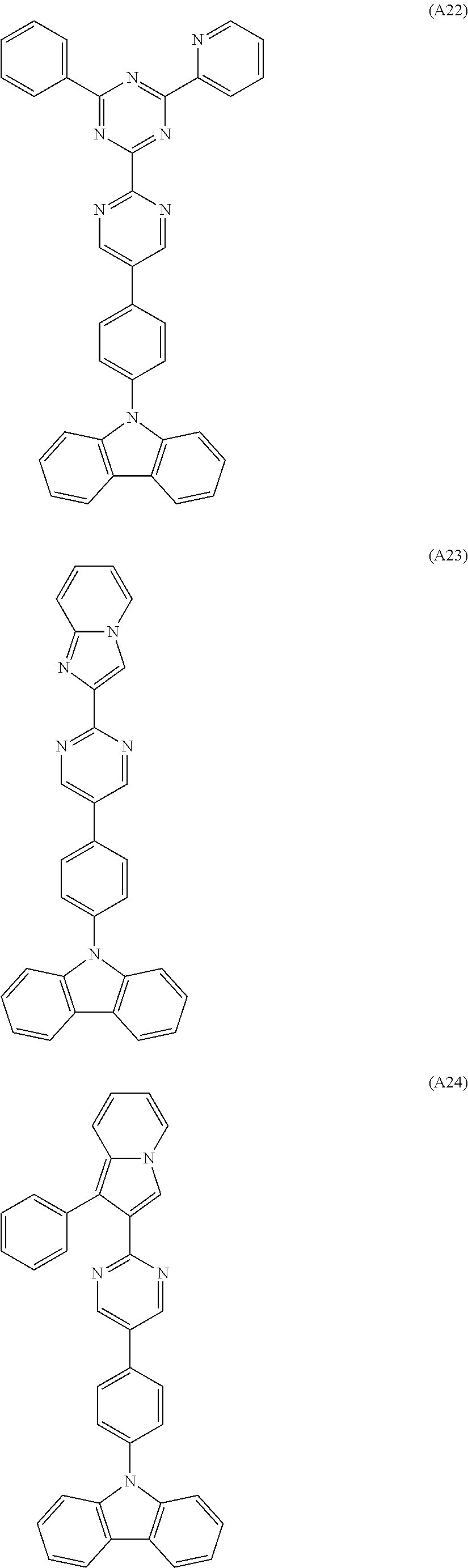


Specific examples of the compound represented by general formula (2) are shown in the following. However, the compound represented by general formula (2) is not limited to these compounds.


It is preferable that the energy gap of the triplet state of a compound represented by general formula (1) or (2) is 2.5 to 3.3 eV and more preferably 2.5 to 3.2 eV.
It is preferable that the energy gap of the singlet state of a compound represented by general formula (1) or (2) is 2.8 to 3.8 eV and more preferably 2.9 to 3.7 eV.
The organic EL device of the present invention comprises an anode, a cathode and an organic thin film layer comprising at least one layer disposed between the anode and the cathode, wherein at least one layer in the organic thin film layer comprises the material for organic electroluminescence devices comprising the compound represented by the above general formula (1) or (2).
It is preferable that the organic EL device of the present invention comprises the material for organic electroluminescence devices comprising the compounds represented by the above general formula (1) or (2) in the light emitting layer, the electron transporting layer or the hole transporting layer.
The organic EL device of the present invention emits bluish light and the purity of color of the emitted light is as excellent as (0.12, 0.10) to (0.17, 0.20). This property is exhibited since the material for organic EL devices comprising the compound represented by general formula (1) or (2) of the present invention has a great energy gap.
It is preferable that the organic EL device of the present invention emits light by a multiplet excitation which is the excitation to the triplet state or higher.
It is preferable that the material for organic electroluminescence devices is a host-material of the organic EL device. The host material is a material into which holes and electrons can be injected and which has the function of transporting holes and electrons and emitting fluorescent light by recombination of holes and electrons.
The compounds represented by general formulae (1) and (2) in the present invention are useful also as the organic host material for phosphorescence devices since the energy gap of the singlet state is as high as 2.8 to 3.8 eV and the energy gap of the triplet state is as high as 2.5 to 3.3 eV.
The phosphorescence device is the organic device which comprises a substance emitting light based on the transition from the energy level of the triplet state to the energy level of the ground singlet state with a stronger intensity than those emitted from other substances, i.e., a phosphorescent material such as organometallic complexes comprising at least one metal selected from Groups 7 to 11 of the Periodic Table, and emits light under an electric field utilizing the so-called phosphorescence.
In the light emitting layer of the organic EL device, in general, the singlet exciton and the triplet exciton are mixed in the formed excited molecules and it is said that the ratio of the amount of the singlet exciton to the amount of the triplet exciton is 1:3 and the triplet exciton is formed in a greater amount. In conventional organic EL devices using the phosphorescence, the exciton contributing to the light emission is the singlet exciton and the triplet exciton does not emit light. Therefore, the triplet exciton is ultimately consumed as heat and the light is emitted by the singlet exciton which is formed in a smaller amount. Therefore, in these organic EL devices, the energy transferred to the triplet exciton in the energy generated by the recombination of holes and electrons causes a great loss.
In contrast, it is considered that, by using the compound of the present invention for the phosphorescence device, the efficiency of light emission three times as great as that of a device using a fluorescence can be obtained since the triplet exciton can be used for emission of light. It is also considered that, when the compound of the present invention is used for the light emitting layer of the phosphorescence device, an excited triplet state having an energy state higher than the excited triplet state of a phosphorescent organometallic complex comprising a metal selected from the Group 7 to 11 of the Periodic Table is formed; the film having a more stable form is formed; the glass transition temperature is higher (Tg: 80 to 160° C.); the holes and the electrons are efficiently transported; the compound is electrochemically and chemically stable; and the formation of impurities which may work as a trap or causes the loss in the light emission is suppressed during the preparation and the use.
The organic EL device of the present invention comprises, as described above, one or more organic thin film layers formed between the anode and the cathode. When the device comprises a single layer, a light emitting layer is formed between the anode and the cathode. The light emitting layer comprises a light emitting material and, further, a hole injecting material for transporting holes injected from the anode to the light emitting material or an electron injecting material for transporting electrons injected from the cathode to the light emitting material. It is preferable that the light emitting material exhibits a very excellent phosphorescent quantum efficiency, has a great ability of transporting both holes and electrons and forms a uniform thin layer. Examples of the organic EL device of the multi-layer type include organic EL device comprising a laminate having a multi-layer construction such as (the anode/the hole injecting layer/the light emitting layer/the cathode), (the anode/the light emitting layer/the electron injecting layer/the cathode) and (the anode/the hole injecting layer/the light emitting layer/the electron injecting layer).
For the light emitting layer, in addition to the compound represented by general formula (1) or (2) of the present invention, conventional host materials, light emitting materials, doping materials, hole injecting materials and electron injecting materials and combinations of these materials may be used, where necessary. By using a multi-layer structure for the organic EL device, decreases in the luminance and the life due to quenching can be prevented and the luminance of emitted light and the efficiency of light emission can be improved with other doping materials. By using other doping materials contributing to the light emission of the phosphorescence in combination, the luminance of emitted light and the efficiency of light emission can be improved in comparison with conventional devices.
In the organic EL device of the present invention, the hole injecting layer, the light emitting layer and the electron injecting layer may each have a multi-layer structure. When the hole injecting layer has a multi-layer structure, the layer into which holes are injected from the electrode is called the hole injecting layer and the layer which receives holes from the hole injecting layer and transports holes to the light emitting layer is called the hole transporting layer. Similarly, when the electron injecting layer has a multi-layer structure, the layer into which electron are injected from the electrode is called the electron injecting layer and the layer which receives electrons from the electron injecting layer and transports electrons to the light emitting layer is called the electron transporting layer. The layers are selected in accordance with the energy levels of the material, heat resistance and adhesion with the organic thin film layers or the metal electrodes.
In the organic EL device of the present invention, the electron transporting layer and/or the hole transporting layer may comprise the material for organic EL devices of the present invention which comprises any of the compounds represented by general formulae (1) and (2). The hole injecting layer, the electron injecting layer and the hole barrier layer may comprise the material for organic EL devices of the present invention. A phosphorescent light emitting compound and the material for organic EL materials of the present invention may be used as a mixture.
Examples of the light emitting material and the host material which can be used for the organic thin film layer in combination with the compound represented by general formula (1) or (2) include anthracene, naphthalene, phenanthrene, pyrene, tetracene, coronen, chrysene, fluoresceine, perylene, phthaloperylene, naphthaloperylene, perynone, phthaloperynone, naphthaloperynone, diphenylbutadiene, tetraphenylbutadiene, coumarine, oxadiazole, aldazine, bisbenzoxazoline, bisstyryl, pyrazine, cyclopentadiene, metal complexes of quinoline, metal complexes of aminoquinoline, metal complexes of benzoquinoline, imines, diphenylethylene, vinylanthracene, diaminoanthracene, diaminocarbazole, pyrane, thiopyrane, polymethine, melocyanine, oxinoid compounds chelated with imidazole, quinacridone, rubrene, stilbene-based derivatives and phosphorescent pigments. However, the light emitting material and the host material are not limited to the compounds described above.
As the light emitting material, phosphorescent organometallic complexes are preferable since the external quantum efficiency of the device can be improved. Examples of the metal in the phosphorescent organometallic complex include ruthenium, rhodium, palladium, silver, rhenium, osmium, iridium, platinum and gold. It is preferable that the organometallic complex is an organometallic compound represented-by the following general formula (3):

In the above general formula, A1 represents a substituted or unsubstituted aromatic hydrocarbon cyclic group or aromatic heterocyclic group which is preferably phenyl group, biphenyl group, naphthyl group, anthryl group, thienyl group, pyridyl group, quinolyl group or isoquinolyl group. Examples of the substituent include halogen atoms such as fluorine atom; alkyl groups having 1 to 30 carbon atoms such as methyl group and ethyl group; alkenyl groups such as vinyl group; alkoxycarbonyl groups having 1 to 30 carbon atoms such as methoxycarbonyl group and ethoxy group; aryloxy groups such as phenoxyl group and benzyloxyl group; dialkylamino groups such as dimethylamino group and diethylamino group; acyl groups such as acetyl group; haloalkyl groups such as trifluoromethyl group; and cyano group.
A2 represents a substituted or unsubstituted aromatic heterocyclic group having nitrogen atom as the atom forming the heterocyclic ring, which is preferably pyridyl group, pirimidyl group, pyrazine group, triazine group, benzothiazole group, benzoxazole group, benzimidazole group, quinolyl group, isoquinolyl group, quinoxaline group or phenanthridine group. Examples of the substituent include the substituents described as the examples of the substituent for the group represented by A1.
The ring having the group represented by A1 and the ring having the group represented by A2 may form one condensed ring. Examples of the condensed ring include 7,8-benzoquinoline group.
Q represents a metal selected from metals of Groups 7 to 11 of the Periodic Table, which is preferably ruthenium, rhodium, palladium, silver, rhenium, osmium, iridium, platinum or gold.
L represents a bidentate ligand, which is preferably selected from ligands of the β-diketone type such as acetylacetonates and pyromellitic acid.
m and n each represent an integer. When Q represents a divalent metal, n=2 and m=0. When Q represents a trivalent metal, n=3 and m=0 or n=2 and m=1.
Specific examples of the organometallic complex represented by the above general formula (3) are shown in the following. However, the organometallic complex is not limited to these compounds.


As the hole injecting material, compounds which have the ability to transport holes, exhibits the excellent effect of receiving holes injected from the anode and the excellent effect of injecting holes to the light emitting layer or the light emitting material, prevents transfer of excitons formed in the light emitting layer to the electron injecting layer or the electron injecting material and has the excellent ability of forming a thin film, are preferable. Examples of the hole injecting compound include phthalocyanine derivatives, naphthalocyanine derivatives, porphyrin derivatives, oxazoles, oxadiazoles, triazoles, imidazoles, imidazolones, imidazolethiones, pyrazolines, pyrazolones, tetrahydroimidazoles, hydrazones, acylhydrazones, polyarylalkanes, stilbene, butadiene, triphenylamine of the benzidine type, triphenylamine of the styrylamine type, triphenylamine of the diamine type, derivatives of the above compounds and macromolecular materials such as polyvinyl-carbazoles, polysilanes and electrically conductive macromolecules. However, the hole injecting material is not limited to these materials.
Among these hole injecting materials, the more effective hole injecting materials are aromatic tertiary amine derivatives and phthalocyanine derivatives. Examples of the aromatic tertiary amine derivative include triphenylamine, tritolylamine, tolyldiphenylamine, N,N′-diphenyl-N,N′-(3-methylphenyl)-1,1′-biphenyl-4,4′-diamine, N,N,N′,N′-(4-methylphenyl)-1,1′-phenyl-4,4′-diamine, phenyl)-1,1′-biphenyl-4,4′-diamine, N,N′-diphenyl-N,N′-dinaphthyl-1,1′-biphenyl-4,4′-diamine, N,N′-(methylphenyl)-N,N′-(4-n-butylphenyl)-phenanthrene-9,10-diamine; N,N-bis(4-di-4-tolylaminophenyl)-4-phenyl-cyclohexane and oligomers and polymers having the skeleton structure of these aromatic tertiary amines. However, the aromatic tertiary amine is not limited to these compounds. Examples of the phthalocyanine (Pc) derivative include phthalocyanine derivatives and naphthalocyanine derivatives such as H2Pc, CuPc, CoPc, NiPc, ZnPc, PdPc, FePc, MnPc, ClAlPc, ClGaPc, ClInPc, ClSnPc, Cl2SiPc, (HO)AlPc, (HO)GaPc, VOPc, TiOPc, MoOPc and GaPc-O—GaPc. However the phthalocyanine derivative is not limited to these compounds.
As the electron injecting material, compounds which have the ability to transport electrons, exhibits the excellent effect of receiving electrons injected from the anode and the excellent effect of injecting electrons to the light emitting layer or the light emitting material, prevents transfer of excitons formed in the light emitting layer to the hole injecting layer and has the excellent ability of forming a thin film, are preferable. Examples of the electron injecting compound include fluorenone, anthraquinodimethane, diphenoquinone, thiopyrane dioxide, oxazoles, oxadiazoles, triazoles, imidazoles, perylenetetracarboxylic acid, quinoxaline, fluorenylidenemethane, anthraquinodimethane, anthrone and derivatives of these compounds. However, the electron injecting material is not limited to these compounds.
Among these electron injecting materials, the more effective electron injecting materials are metal complex compounds and five-membered derivatives having nitrogen. Examples of the metal complex compound include 8-hydroxyquinolinatolithium, bis(8-hydroxyquinolinato)zinc, bis(8-hydroxyquinolinato)copper, bis(8-hydroxyquinolinato)manganese, tris(8-hydroxyquinolinato)aluminum, tris(2-methyl-8-hydroxyquinolinato)aluminum, tris(8-hydroxyquinolinato)-gallium, bis(10-hydroxybenzo[h]quinolinato)beryllium, bis(10-hydroxybenzo[h]quinolinato)zinc, bis(2-methyl-8-quinolinato)chlorogallium, bis(2-methyl-8-quinolinato) (o-cresolato)gallium, bis(2-methyl-8-quinolinato) (1-naphtholato)aluminum and bis(2-methyl-8-quinolinato) (2-naphtholato)-gallium. However the electron injecting material is not limited to these compounds.
As the five-membered derivative having nitrogen, oxazoles, thiazoles, oxadiazoles, thiadiazoles, triazoles and derivatives of these compounds are preferable. Examples of the five-membered derivative having nitrogen include bis(1-phenyl)-1,3,4-oxazole, dimethylPOPOP, 2,5-bis(1-phenyl)-1,3,4-thiazole, 2,5-bis(1-phenyl)-1,3,4-oxadiazole, 2-(4′-tert-butylphenyl)-5-(4″-biphenyl)-1,3,5-oxadiazole, 2,5-bis(1-naphthyl)-1,3,4-oxadiazole, 1,4-bis[2-(5-phenyloxadiazolyl)]benzene, 1,4-bis[2-(5-phenyloxadiazolyl)-4-tert-butylbenzene], 2-(4′-tert-butylphenyl)-5(4″-biphenyl)-1,3,4-thiadiazole, 2,5-bis(1-naphthyl)-1,3,4-thiadiazole, 1,4-bis[2-(5-phenylthiadiazolyl)]benzene, 2-(4′-tert-butylphenyl)-5-(4″-biphenyl)-1,3,4-triazole, 2,5-bis(1-naphthyl)-1,3,4-triazole and 1,4-bis[2-(5-phenyl-triazolyl)]benzene. However, the five-membered derivative having nitrogen is not limited to these compounds.
The property of charge injection can be improved by adding an electron-accepting compound to the hole injecting material and an electron-donating compound to the electron injecting material.
As the electrically conductive material used for the anode of the organic EL device of the present invention, a material having a work function greater than 4 eV is suitable and carbon, aluminum, vanadium, iron, cobalt, nickel, tungsten, silver, gold, platinum, palladium, alloys of these metals, metal oxides such as tin oxides and indium oxide used for ITO substrates and NESA substrates and organic electrically conductive resins such as polythiophene and polypyrrol are used. As the electrically conductive material used for the cathode, a material having a work function smaller than 4 eV is suitable and magnesium, calcium, tin, lead, titanium, yttrium, lithium, ruthenium, manganese, aluminum and alloys of these metals are used. However, the electrically conductive material used for the cathode is not limited to these materials. Typical examples of the alloy include magnesium/silver, magnesium/indium and lithium/aluminum. However, the alloy is not limited to these alloys. The composition of the alloy is controlled by the temperature of the source of vaporization, the atmosphere and the degree of vacuum and a suitable composition is selected. The anode and the cathode may be formed with a structure having two or more layers, where necessary.
The organic EL device of the present invention may comprise an inorganic compound layer between at least one of the electrodes and the above organic thin film layer. Examples of the inorganic compound used for the inorganic compound layer include various types of oxides, nitrides and oxide nitrides such as alkali metal oxides, alkaline earth metal oxides, rare earth oxides, alkali metal halides, alkaline earth metal halides, rare earth halides, SiOx, AlOx, SiNx, SiON, AlON, GeOx, LiOx, LiON, TiOx, TiON, TaOx, TaON, TaNx and C. In particular, as the component contacting the anode, SiOx, AlOx, SiNx, SiON, AlON, GeOx and C are preferable since a stable interface layer of injection is formed. As the component contacting the cathode, LiF, MgF2, CaF2 and NaF are preferable.
In the organic EL device of the present invention, it is preferable that at least one face is sufficiently transparent in the region of the wavelength of the light emitted by the device so that the light emission is achieved efficiently. It is preferable that the substrate is also transparent.
For the transparent electrode, the conditions in the vapor deposition or the sputtering are set so that the prescribed transparency is surely obtained using the above electrically conductive material. It is preferable that the electrode of the light emitting face has a transmittance of light of 10% or greater. The substrate is not particularly limited as long as the substrate has the mechanical and thermal strength and is transparent. Examples of the substrate include glass substrates and transparent films of resins. Examples of the transparent film of a resin include films of polyethylene, ethylene-vinyl acetate copolymers, ethylene-vinyl alcohol copolymers, polystyrene, polymethyl methacrylate, polyvinyl chloride, polyvinyl alcohol, polyvinyl butyral, nylon, polyether ether ketones, polysulfones, polyether sulfones, tetrafluoroethylene-perfluoroalkyl vinyl ether copolymers, polyvinyl fluoride, tetrafluoro-ethylene-ethylene copolymers, tetrafluoroethylene-hexafluoropropylene copolymers, polychlorotrifluoroethylene, polivinylidene fluoride, polyesters, polycarbonates, polyurethanes, polyether imides, polyimides and polypropylene.
In the organic EL device of the present invention, it is possible that a protective layer is formed on the surface of the device or the entire device is covered with a silicone oil or a resin so that stability to the temperature, the humidity and the atmosphere is improved.
For the formation of each layer of the organic EL device of the present invention, any of the dry processes of film formation such as the vacuum vapor deposition, the sputtering, the plasma plating and the ion plating and the wet processes of film formation such as the spin coating, the dipping and the flow coating, can be applied. The thickness of each film is not particularly limited. However, it is necessary that the thickness of the film be set at a suitable value. When the thickness is excessively great, application of a greater voltage is necessary to obtain the same output of the light and the efficiency of light emission decreases. When the thickness is excessively small, pin holes are formed and sufficient light emission cannot be obtained even when an electric field is applied. In general, a thickness in the range of 5 nm to 10 μm is suitable and a thickness in the range of 10 nm to 0.2 μm is preferable.
When the wet process of film formation is used, the material forming each layer is dissolved or suspended in a suitable solvent such as ethanol, chloroform, tetrahydrofuran and dioxane and a thin film is formed from the obtained solution or suspension. Any of the above solvents can be used. For any of the layers, suitable resins and additives may be used to improve the property for film formation and to prevent formation of pin holes in the film. Examples of the resin which can be used include insulating resins such as polystyrene, polycarbonates, polyarylates, polyesters, polyamides, polyurethanes, polysulfones, polymethyl methacrylate, polymethyl acrylate, cellulose and copolymers of these resins; photoconductive resins such as poly-N-vinylcarbazole and polysilanes; and electrically conductive resins such as polythiophene and polypyrrol. Examples of the additive include antioxidants, ultraviolet light absorbents and plasticizers.
As described above, by using the compound represented by general formula (1) or (2) for the organic thin film layer of the organic EL device of the present invention, the organic EL device emitting blue light with a high purity of color can be obtained. This organic EL device can be advantageously used for a photosensitive member for electronic photograph, a planar light emitting member such as a flat panel display of wall televisions, a back light of copiers, printers and liquid crystal displays, a light source for instruments, a display panel, a marking light and an accessory.
The present invention will be described more specifically with reference to examples in the following. However, the present invention is not limited to the examples.
The triplet energy gap and the singlet energy gap of a compound were measured in accordance with the following methods.
(1) Measurement of the Triplet Energy Gap
The lowest excited triplet energy level T1 was measured. The phosphorescence spectrum of a sample was measured (10 μmoles/liter; an EPA (diethyl ether:isopentane:ethanol=5:5:2 by volume) solution; 77K; a quartz cell; FLUOROLOG II manufactured by SPEX Company). A tangent was drawn to the increasing line at the short wavelength side of the phosphorescence spectrum and the wavelength at the intersection of the tangent and the abscissa (the end of light emission) was obtained. The obtained wavelength was converted into the energy.
(2) Measurement of the Singlet Energy Gap
The excited singlet energy gap was measured. Using a toluene solution (10−5 moles/liter) of a sample, the absorption spectrum was obtained by a spectrometer for absorption of ultraviolet and visible light manufactured by HITACHI Co. Ltd. A tangent was drawn to the increasing line at the long wavelength side of the spectrum and the wavelength at the intersection of the tangent and the abscissa (the end of absorption) was obtained. The obtained wavelength was converted into the energy.
The route of synthesis of Compound (A5) is shown in the following.

(1) Synthesis of Intermediate Compound (A)
2,4′-Dibromoacetophenone in an amount of 15 g (54 mmoles) was dissolved into 100 ml of ethanol. To the obtained solution, 7.0 g of sodium hydrogencarbonate and 5.2 g (55 mmoles) of 2-aminopyridine were added and the resultant mixture was heated for 9 hours under the refluxing condition. After the reaction was completed, the mixture was cooled at the room temperature. The formed crystals were separated by filtration and washed with water and ethanol and 12.5 g (the yield: 85%) of Intermediate Compound (A) was obtained.
(2) Synthesis of Compound (A5)
Into a reactor, 6.1 g (19 mmoles) of 3,6-diphenylcarbazole, 6.3 g (23 mmoles) of Intermediate Compound (A), 0.2 g of copper powder, 1.7 g of 18-crown-6 and 2.9 g (21 mmoles) of potassium carbonate were placed and 30 ml of o-dichlorobenzene was added as the solvent. The resultant mixture was heated at 200° C. in a silicone oil bath under a nitrogen stream and the reaction was allowed to proceed for 48 hours. After the reaction was completed, the reaction mixture was filtered under suction before being cooled and the obtained filtrate was concentrated using an evaporator. To the obtained oily product, 30 ml of methanol was added. The formed solid substance was separated by filtration under a reduced pressure and a gray solid substance was obtained. The obtained solid substance was recrystallized from benzene and 3.0 g (the yield: 31%) of white crystals were obtained. It was confirmed by 90 MHz 1H-NMR and FD-MS (the field desorption mass analysis) that the obtained crystals were the target substance (A5). The result of the measurement by FD-MS is shown in the following:
FD-MS calcd. for C37H25N3=511; found: m/z=511 (M+, 100)
The values of the energy gaps were obtained in accordance with the methods described above and the results are shown in Table 3.
The route of synthesis of Compound (A3) is shown in the following.

(1) Synthesis of Intermediate Compound (B)
4-Bromobenzaldehyde in an amount of 15 g (81 mmoles) was dissolved into 300 ml of ethanol. To the obtained solution, 10 g (83 mmoles) of 2-acetylpyridine and 15 g (81 mmoles) of a 28% methanol solution of sodium methoxide were added and the resultant mixture was stirred at the room temperature for 7 hours. After the reaction was completed, the formed crystals were separated by filtration and washed with ethanol and 9:5 g (the yield: 41%) of Intermediate Compound (B) was obtained.
(2) Synthesis of Intermediate Compound (C)
Intermediate Compound (B) in an amount of 9.5 g (33 mmoles) was dissolved into 80 ml of ethanol. To the obtained solution, 5.2 g (34 mmoles) of benzamidine hydrochloride and 2.6 g (65 mmoles) of sodium hydroxide were added and the resultant mixture was heated for 15 hours under the refluxing condition. After the reaction was completed, the mixture was cooled at the room temperature. The formed crystals were separated by filtration and washed with water and ethanol and 3.46 g (the yield: 27%) of Intermediate Compound (C) was obtained.
(3) Synthesis of Compound (A3)
Into a reactor, 6.1 g (19 mmoles) of 3,6-diphenylcarbazole, 8.9 g (23 mmoles) of Intermediate Compound (C), 0.2 g of copper powder, 1.7 g of 18-crown-6 and 2.9 g (21 mmoles) of potassium carbonate were placed and 30 ml of o-dichlorobenzene was added as the solvent. The resultant mixture was heated at 200° C. in a silicone oil bath under a nitrogen stream and the reaction was allowed to proceed for 48 hours. After the reaction was completed, the reaction mixture was filtered under suction before being cooled and the obtained filtrate was concentrated using an evaporator. To the obtained oily product, 30 ml of methanol was added. The formed solid substance was separated by filtration under a reduced pressure and a gray solid substance was obtained. The obtained solid substance was recrystallized from benzene and 3.9 g (the yield: 33%) of white crystals were obtained. It was confirmed by 90 MHz 1H-NMR and FD-MS that the obtained crystals were the target substance (A3). The result of the measurement by FD-MS is shown in the following:
FD-MS calcd. for C45H30N4=626; found: m/z=626 (M+, 100)
The values of the energy gaps were obtained in accordance with the same methods as those in Synthesis Example 1 and the results are shown in Table 3.
The route of synthesis of Compound (A26) is shown in the following.

(1) Synthesis of Intermediate Compound (D)
Into a reactor, 33 g (0.20 moles) of carbazole, 68 g (0.24 moles) of p-bromoiodobenzene, 2.0 g of copper powder, 18 g of 18-crown-6 and 30 g (0.22 moles) of potassium carbonate were placed and 300 ml of o-dichlorobenzene was added as the solvent. The resultant mixture was heated at 200° C. in a silicone oil bath under a nitrogen stream and the reaction was allowed to proceed for 24 hours. After the reaction was completed, the reaction mixture was filtered under suction using a Buchner funnel before being cooled and the obtained filtrate was concentrated using an evaporator. To the obtained oily product, 30 ml of methanol was added. The formed solid substance was separated by filtration under a reduced pressure and a gray solid substance was obtained. The obtained solid substance was recrystallized from benzene and 31 g (the yield: 49%) of white crystals were obtained.
(2) Synthesis of Compound (A26)
Into a reactor, 5.4 g (20 mmoles) of 2-biphenylindole, 7.7 g (24 mmoles) of Intermediate Compound (D), 0.2 g of copper powder, 1.8 g of 18-crown-6 and 3.0 g (22 mmoles) of potassium carbonate were placed and 30 ml of o-dichlorobenzene was added as the solvent. The resultant mixture was heated at 200° C. in a silicone oil bath under a nitrogen stream and the reaction was allowed to proceed for 48 hours. After the reaction was completed, the reaction mixture was filtered under suction before being cooled and the obtained filtrate was concentrated using an evaporator. To the obtained oily product, 30 ml of methanol was added. The formed solid substance was separated by filtration under a reduced pressure and a gray solid substance was obtained. The obtained solid substance was recrystallized from benzene and 1.7 g (the yield: 17%) of white crystals were obtained. It was confirmed by 90 MHz 1H-NMR and FD-MS that the obtained crystals were the target substance (A26). The result of the measurement by FD-MS is shown in the following:
FD-MS calcd. for C38H26N2=510; found: m/z=510 (M+, 100)
The values of the energy gaps were obtained in accordance with the same methods as those in Synthesis Example 1 and the results are shown in Table 3.
The route of synthesis of Compound (A27) is shown in the following.

In accordance with the same procedures as those conducted in Synthesis Example 3 (2) except that 2-biphenyl-3-phenylindole was used in place of 2-biphenylindole, 2.2 g (the yield: 19%) of white crystals were obtained. It was confirmed by 90 MHz 1H-NMR and FD-MS that the obtained crystals were the target substance (A27). The result of the measurement by FD-MS is shown in the following:
FD-MS calcd. for C44H30N2=586; found: m/z=586 (M+, 100)
The values of the energy gaps were obtained in accordance with the same methods as those in Synthesis Example 1 and the results are shown in Table 3.
The route of synthesis of Compound (A11) is shown in the following.

(1) Synthesis of Intermediate Compound (E)
3,6-Biphenyl-9-p-bromophenylcarbazole in an amount of 7.6 g (16 mmoles) was dissolved into 70 ml of ether. To the obtained solution, 12 ml of a hexane solution (1.6 M) of n-butyllithium was added at −60° C. After the resultant solution was stirred at a temperature between −60° C. and 0° C. for 2 hours, the solution was cooled at −60° C. again and a solution obtained by diluting 8.8 g of triisopropyl borate with 10 ml of ether was added dropwise. After the resultant mixture was stirred at a temperature between −60° C. and 0° C. for 2 hours, the reaction was quenched by adding a 5% aqueous solution of hydrochloric acid. The formed crystals were separated by filtration and washed with water and methanol and 4.0 g (the yield: 58%) of Intermediate Compound (E) was obtained.
(2) Synthesis of Compound (A11)
2-(4′-Bromophenyl)imidazo[1,2-a]pyridine in an amount of 2.0 g (7.3 mmoles), 3.5 g (8.0 mmoles) of Intermediate Compound (E), 0.2 g of copper powder and 0.17 g of tetrakis(triphenylphosphine)palladium were dissolved into 30 ml of 1,2-dimethoxyethane. To the resultant solution, 12 ml of a 2.0 M aqueous solution of sodium carbonate was added and the obtained solution was heated for 8 hours under the refluxing condition. After the reaction was completed, the formed solid substance was dissolved into dichloromethane, washed with water and dried with sodium sulfate. After the solvent was removed by distillation, the obtained product was washed with methanol and 2.0 g (the yield: 47%) of yellowish white solid substance was obtained. It was confirmed by 90 MHz 1H-NMR and FD-MS that the obtained solid substance was the target substance (A11). The result of the measurement by FD-MS is shown in the following:
FD-MS calcd. for C43H29N3=587; found: m/z=587 (M+, 100)
The values of the energy gaps were obtained in accordance with the same methods as those in Synthesis Example 1 and the results are shown in Table 3.
The route of synthesis of Compound (A9) is shown in the following.

Intermediate Compound (C) obtained in Synthesis Example 2 in an amount of 2.0 g (5.2 mmoles), 1.7 g (5.8 mmoles) of 4-(9′-carbazolyl)-phenylboric acid and 0.11 g of tetrakis(triphenylphosphine)palladium were dissolved into 20 ml of 1,2-dimethoxyethane. To the resultant solution, 9 ml of a 2.0 M aqueous solution of sodium carbonate was added and the obtained solution was heated for 8 hours under the refluxing condition. After the reaction was completed, the formed solid substance was dissolved into dichloromethane, washed with water and dried with sodium sulfate. After the solvent was removed by distillation, the obtained product was washed with methanol and 1.8 g (the yield: 62%) of yellowish white solid substance was obtained. It was confirmed by 90 MHz 1H-NMR and FD-MS that the obtained solid substance was the target substance (A9). The result of the measurement by FD-MS is shown in the following:
FD-MS calcd. for C39H26N4=550; found: m/z=550 (M+, 100)
The values of the energy gaps were obtained in accordance with the same methods as those in Synthesis Example 1 and the results are shown in Table 3.
The route of synthesis of Compound (A43) is shown in the following.

Under a stream of argon, 2.33 g (10 mmoles) of 2,3-dicyano-5-(p-bromophenyl)-7-methyl-6H-1,4-diazepine, 2 g (12 mmoles) of carbazole, 0.14 g (1.5% by mole) of tris(dibenzylideneacetone)dipalladium, 0.06 g (3% by mole) of tri-t-butylphosphine, 2.0 g (22 mmoles) of sodium t-butoxide and 100 ml of dry toluene were placed into a 200 ml three-necked flask equipped with a condenser and the resultant mixture was heated at 100° C. under stirring for one night. After the reaction was completed, the formed crystals were separated by filtration and washed with 100 ml of methanol and 1.2 g (3 mmoles) (the yield: 30%) of a light yellow powder was obtained. It was confirmed by the measurements of NMR, IR and FD-MS that the obtained powder was the target substance (A43). The result of the measurement by FD-MS is shown in the following:
FD-MS calcd. for C26H17N5=399; found: m/z=399 (M+, 100)
The route of synthesis of Compound (A45) is shown in the following.

Under a stream of argon, 4.5 g (10 mmole) of 2,3-dicyano-5,7-bis(p-bromophenyl)-6H-1,4-diazepine, 4 g (24 mmoles) of carbazole, 0.28 g (1.5% by mole) of tris(dibenzylideneacetone)dipalladium, 0.12 g (3% by mole) of tri-t-butylphosphine, 4.2 g (442 mmoles) of sodium t-butoxide and 160 ml of dry toluene were placed into a 200 ml three-necked flask equipped with a condenser and the resultant mixture was heated at 100° C. under stirring for 18 hours. After the reaction was completed, the formed crystals were separated by filtration and washed with 100 ml of methanol and 1.8 g (2.9 mmoles) (the yield: 29%) of a white powder was obtained. It was confirmed by the measurements of NMR, IR and FD-MS that the obtained powder was the target substance (A45). The result of the measurement by FD-MS is shown in the following:
FD-MS calcd. for C43H26N6=626; found: m/z=626 (M+, 100)
The route of synthesis of Compound (B9) is shown in the following.

Under the atmosphere of argon, 11 g (32 mmole, 2.6 eq) of 4-(2′-phenyl-4′-pyridylpirimidin-6′-yl)phenylboric acid, 5 g (12 mmoles) of 3,6-dibromo-9-phenylcarbazole and 0.55 g (0.48 mmoles, 2% Pd) of tetrakis(triphenylphosphine)palladium(0) were suspended in 100 ml of 1,2-dimethoxyethane. To the resultant suspension, 10.2 g of a 2 M aqueous solution of sodium carbonate (96 mmoles, 3 eq/50 ml) was added and the resultant mixture was heated for 10 hours under the refluxing condition. After the organic layer was separated and concentrated, the product was purified in accordance with the column chromatography and 8.5 g (the yield: 83%) of a white solid substance was obtained. It was confirmed by 90 MHz 1H-NMR and FD-MS that the obtained solid substance was the target substance (B9). The result of the measurement by FD-MS is shown in the following:
FD-MS calcd. for C60H39N7=857; found: m/z=857 (M+, 100)
The values of the energy gaps were obtained in accordance with the same methods as those in Synthesis Example 1 and the results are shown in Table 3.
The route of synthesis of Compound (B11) is shown in the following.

Under the atmosphere of argon, 7.6 g (32 mmole, 2.6 eq) of 4-(imidazopyridin-2′-yl)phenylboric acid, 5 g (12 mmoles) of 3,6-dibromo-9-phenylcarbazole and 0.55 g (0.48 mmoles, 2% Pd) of tetrakis(triphenylphosphine)palladium(0) were suspended in 100 ml of 1,2-dimethoxyethane. To the resultant suspension, 10.2 g of a 2 M aqueous solution of sodium carbonate (96 mmoles, 3 eq/50 ml) was added and the resultant mixture was heated for 10 hours under the refluxing condition. After the organic layer was separated and concentrated, the product was purified in accordance with the column chromatography and 5.7 g (the yield: 76%) of a white solid substance was obtained. It was confirmed by 90 MHz 1H-NMR and FD-MS that the obtained solid substance was the target substance (B11). The result of the measurement by FD-MS is shown in the following:
FD-MS calcd. for C44H29N5=627; found: m/z=627 (M+, 100)
The values of the energy gaps were obtained in accordance with the same methods as those in Synthesis Example 1 and the results are shown in Table 3.
The route of synthesis of Compound (A72) is shown in the following.

(1) Synthesis of Intermediate Compound (F)
In accordance with the same procedures as those conducted in Synthesis Example 2 (1) except that acetophenone was used in place of 2-acetylpyridine, 29.4 g (the yield: 84%) of Intermediate Compound (F) was obtained.
(2) Synthesis of Intermediate Compound (G)
Intermediate Compound (F) in an amount of 9.0 g (31 mmoles), 8.7 g (31 mmoles) of 1-phenylpyridinium bromide and 19.3 g (250 mmoles) of ammonium acetate were suspended into 27 ml of acetic acid and the resultant suspension was heated for 12 hours under the refluxing condition. The reaction solution was then cooled at the room temperature. Toluene and water were added and the resultant mixture was separated into two layers. The organic layer was washed with a 10% aqueous solution of sodium hydroxide and a saturated aqueous solution of sodium chloride, successively, and dried with anhydrous sodium sulfate. After the organic solvent was removed by distillation under a reduced pressure, 27 ml of ethanol was added. The formed crystals were separated by filtration and washed with ethanol and 10.6 g (the yield: 88%) of Intermediate Compound (G) was obtained.
(3) Synthesis of Compound (A72)
Intermediate Compound (G) in an amount of 3.5 g (9 mmoles), 1.7 g (10 mmoles) of carbazole, 0.09 g (0.5 mmoles) of copper iodide and 4.0 g (19 mmoles) of potassium phosphate were suspended into 18 ml of 1,4-dioxane. To the obtained suspension, 0.5 ml (4 mmoles) of trans-1,2-cyclohexanediamine was added. Under the atmosphere of argon, the resultant mixture was heated for 18 hours under the refluxing condition. The reaction solution was then cooled at the room temperature. Methylene chloride and water were added and the resultant mixture was separated into two layers. The organic layer was washed with a 5% aqueous solution of hydrochloric acid and water, successively, and dried with anhydrous sodium sulfate. After the organic solvent was removed by distillation, 15 ml of ethyl acetate was added. The formed crystals were separated by filtration and washed with ethyl acetate and 3.5 g (the yield: 83%) of yellowish white crystals were obtained. It was confirmed by 90 MHz 1H-NMR and FD-MS that the obtained crystals were the target substance (A72). The result of the measurement by FD-MS is shown in the following:
FD-MS calcd. for C35H24N2=472; found: m/z=472 (M+, 100)
The values of the energy gaps were obtained in accordance with the same methods as those in Synthesis Example 1 and the results are shown in Table 3.
The route of synthesis of Compound (A73) is shown in the following.

(1) Synthesis of Intermediate Compound (H)
In accordance with the same procedures as those conducted in Synthesis Example 2 (2) except that Intermediate Compound (F) obtained in Synthesis Example 11 was used in place of Intermediate Compound (B), 7.8 g (the yield: 61%) of Intermediate Compound (H) was obtained.
(2) Synthesis of Compound (A73)
In accordance with the same procedures as those conducted in Synthesis Example 11 (3) except that Intermediate Compound (H) was used in place of Intermediate Compound (G), 3.3 g (the yield: 76%) of yellowish white crystals were obtained. It was confirmed by 90 MHz 1H-NMR and FD-MS that the obtained crystals were the target substance (A73). The result of the measurement by FD-MS is shown in the following:
FD-MS calcd. for C34H23N3=473; found: m/z=473 (M+, 100)
The values of the energy gaps were obtained in accordance with the same methods as those in Synthesis Example 1 and the results are shown in Table 3.
The route of synthesis of Compound (A113) is shown in the following.

In accordance with the same procedures as those conducted in Synthesis Example 11 (3) except that Intermediate Compound (C) obtained in Synthesis Example 2 was used in place of Intermediate Compound (G), 1.5 g (the yield: 50%) of yellowish white crystals were obtained. It was confirmed by 90 MHz 1H-NMR and FD-MS that the obtained crystals were the target substance (A113). The result of the measurement by FD-MS is shown in the following:
FD-MS calcd. for C33H22N4=474; found: m/z=474 (M+, 100)
The values of the energy gaps were obtained in accordance with the same methods as those in Synthesis Example 1 and the results are shown in Table 3.
The route of synthesis of Compound (A98) is shown in the following.

(1) Synthesis of Intermediate Compound (J)
In accordance with the same procedures as those conducted in Synthesis Example 2 (1) except that 3,5-dibromobenzaldehyde was used in place of 4-bromobenzaldehyde and acetophenone was used in place of 2-acetylpyridine, 19.2 g (the yield: 92%) of Intermediate Compound (J) was obtained.
(2) Synthesis of Intermediate Compound (K)
In accordance with the same procedures as those conducted in Synthesis Example 2 (2) except that Intermediate Compound (J) was used in place of Intermediate Compound (B), 5.5 g (the yield: 45%) of Intermediate Compound (K) was obtained.
(3) Synthesis of Compound (A98)
Intermediate Compound (K) in an amount of 3.0 g (6 mmoles), 2.3 g (14 mmoles) of carbazole, 0.12 g (0.6 mmoles) of copper iodide and 4.2 g (20 mmoles) of potassium phosphate were suspended into 21 ml of 1,4-dioxane. To the obtained suspension, 0.8 ml (6 mmoles) of trans-1,2-cyclohexanediamine was added. Under the atmosphere of argon, the resultant mixture was heated for 18 hours under the refluxing condition. The reaction solution was then cooled at the room temperature. Methylene chloride and water were added and the resultant mixture was separated into two layers. The organic layer was washed with water and dried with anhydrous sodium sulfate. After the organic solvent was removed by distillation under a reduced pressure, the residue of distillation was suspended into 21 ml of dioxane. To the obtained suspension, 0.12 g (0.6 mmoles) of copper iodide, 2.9 g (14 mmoles) of potassium phosphate and 0.8 ml (6 mmoles) of trans-1,2-cyclohexanediamine were added. Under the atmosphere of argon, the resultant mixture was heated for 18 hours under the refluxing condition. The reaction solution was then cooled at the room temperature. Methylene chloride and water were added and the resultant mixture was separated into two layers. The organic layer was washed with water and dried with anhydrous sodium sulfate. After the organic solvent was removed by distillation under a reduced pressure, 30 ml of ethyl acetate was added. The formed crystals were separated by filtration and washed with ethyl acetate and 3.3 g (the yield: 80%) of yellowish white crystals were obtained. It was confirmed by 90 MHz 1H-NMR and FD-MS that the obtained crystals were the target substance (A98). The result of the measurement by FD-MS is shown in the following:
FD-MS calcd. for C46H30N4=638; found: m/z=638 (M+, 100)
The values of the energy gaps were obtained in accordance with the same methods as those in Synthesis Example 1 and the results are shown in Table 3.
The route of synthesis of Compound (A105) is shown in the following.

(1) Synthesis of Intermediate Compound (M)
In accordance with the same procedures as those conducted in Synthesis Example 11 (2) except that Intermediate Compound (J) obtained in Synthesis Example 14 (1) was used in place of Intermediate Compound (F), 10.0 g (the yield: 88%) of Intermediate Compound (M) was obtained.
(2) Synthesis of Compound (A105)
In accordance with the same procedures as those conducted in Synthesis Example 14 (3) except that Intermediate Compound (M) was used in place of Intermediate Compound (K), 2.9 g (the yield: 71%) of yellowish white crystals were obtained. It was confirmed by 90 MHz 1H-NMR and FD-MS that the obtained crystals were the target substance (A105). The result of the measurement by FD-MS is shown in the following:
FD-MS calcd. for C47H31N3=637; found: m/z=637 (M+, 100)
The values of the energy gaps were obtained in accordance with the same methods as those in Synthesis Example 1 and the results are shown in Table 3.
The route of synthesis of Compound (A108) is shown in the following.

(1) Synthesis of Intermediate Compound (N)
1,3,5-Tribromobenzene in an amount of 13.0 g (41 mmoles), 10.0 g (45 mmoles) of 3,5-diphenylpyrazole, 0.8 g (4 mmoles) of copper iodide and 11.9 g (86 mmoles) of potassium carbonate were suspended into 50 ml of 1,4-dioxane. To the obtained suspension, 4.9 ml (41 mmoles) of trans-1,2-cyclohexanediamine was added. Under the atmosphere of argon, the resultant mixture was heated for 18 hours under the refluxing condition. The reaction solution was then cooled at the room temperature. Methylene chloride and water were added and the resultant mixture was separated into two layers. The organic layer was washed with water and dried with anhydrous sodium sulfate. After the organic solvent was removed by distillation under a reduced pressure, the remaining product was purified in accordance with the silica gel column chromatography and 2.0 g (the yield: 11%) of Intermediate Compound (N) was obtained.
(2) Synthesis of Compound (A108)
Intermediate Compound (N) in an amount of 2.0 g (4 mmoles), 1.4 g (8 mmoles) of carbazole, 0.08 g (0.4 mmoles) of copper iodide and 2.9 g (14 mmoles) of potassium phosphate were suspended into 15 ml of 1,4-dioxane. To the obtained suspension, 0.5 ml (4 mmoles) of trans-1,2-cyclohexanediamine was added. Under the atmosphere of argon, the resultant mixture was heated for 18 hours under the refluxing condition. The reaction solution was then cooled at the room temperature. Methylene chloride and water were added and the resultant mixture was separated into two layers. The organic layer was washed with water and dried with anhydrous sodium sulfate. After the organic solvent was removed by distillation, the residue of distillation was suspended into 15 ml of 1,4-dioxane. To the obtained suspension, 0.08 g (0.4 mmoles) of copper iodide, 2.9 g (14 mmoles) of potassium phosphate and 0.5 ml (4 mmoles) of trans-1,2-cyclohexanediamine were added. Under the atmosphere of argon, the resultant mixture was heated for 14 hours under the refluxing condition. The reaction solution was then cooled at the room temperature. Methylene chloride and water were added and the resultant mixture was separated into two layers. The organic layer was washed with water and dried with anhydrous sodium sulfate. After the organic solvent was removed by distillation under a reduced pressure, 5 ml of ethanol and 15 ml of ethyl acetate were added. The formed crystals were separated by filtration and washed with a mixed solvent containing ethyl acetate and ethanol in relative amounts by, volume of 5:2 and 2.4 g (the yield: 87%) of yellowish white crystals were obtained. It was confirmed by 96 MHz 1H-NMR and FD-MS that the obtained crystals were the target substance (A108). The result of the measurement by FD-MS is shown in the following:
FD-MS calcd. for C45H30N4=626; found: m/z=626 (M+, 100)
The values of the energy gaps were obtained in accordance with the same methods as those in Synthesis Example 1 and the results are shown in Table 3.
| TABLE 3 | ||||
| Singlet energy | Triplet energy | |||
| Compound | gap (eV) | gap (eV) | ||
| Synthesis Example 1 | A5 | 3.2 | 2.7 |
| Synthesis Example 2 | A3 | 3.1 | 2.7 |
| Synthesis Example 3 | A26 | 3.1 | 2.6 |
| Synthesis Example 4 | A27 | 3.0 | 2.6 |
| Synthesis Example 5 | A11 | 3.0 | 2.7 |
| Synthesis Example 6 | A9 | 3.1 | 2.5 |
| Synthesis Example 9 | B9 | 3.2 | 2.6 |
| Synthesis Example 10 | B11 | 3.2 | 2.7 |
| Synthesis Example 11 | A72 | 3.5 | 2.8 |
| Synthesis Example 12 | A73 | 3.3 | 2.8 |
| Synthesis Example 13 | A113 | 3.2 | 2.7 |
| Synthesis Example 14 | A98 | 3.5 | 2.9 |
| Synthesis Example 15 | A105 | 3.4 | 2.9 |
| Synthesis Example 16 | A108 | 3.7 | 3.0 |
A glass substrate (manufactured by GEOMATEC Company) of 25 mm×75 mm×1.1 mm thickness having an ITO transparent electrode was cleaned by application of ultrasonic wave in isopropyl alcohol for 5 minutes and then by exposure to ozone generated by ultraviolet light for 30 minutes. The glass substrate having the transparent electrode lines which had been cleaned was attached to a substrate holder of a vacuum vapor deposition apparatus. On the surface of the cleaned substrate at the side having the transparent electrode, a film of N,N′-bis(N,N′-diphenyl-4-aminophenyl)-N,N′-diphenyl-4,4′-diamino-1,1′-biphenyl (a film of TPD232) having a thickness of 60 nm was formed in a manner such that the formed film covered the transparent electrode. The formed film of TPD232 worked as the hole injecting layer. On the formed film of TPD232, a film of 4,4′-bis[N-(1-naphthyl)-N-phenylamino]biphenyl (a film of NPD) having a thickness of 20 nm was formed by vapor deposition. The formed film of NPD worked as the hole transporting layer. On the formed film of NPD, a film of the above Compound (A5) having a thickness of 40 nm was formed by vapor deposition. At the same time, Compound (D1) shown in the following was vapor deposited in an amount such that the ratio of the amounts by weight of Compound (A5) to Compound (D1) was 40:3. Compound (D1) is a light emitting Compound having a singlet energy as low as 2.79 eV so that blue light is emitted. The formed mixed film of Compound (A5) and Compound (D1) worked as the light emitting layer. On the film formed above, a film of BAlq shown in the following (Me means methyl group) having a thickness of 20 nm was formed. The film of BAlq worked as the electron injecting layer. Thereafter, Li (the source of lithium: manufactured by SAES GETTERS Company) as the reducing dopant and Alq were binary vapor deposited and an Alq:Li film having a thickness of 10 nm was formed as the second electron injecting layer (the cathode). On the formed Alq:Li film, metallic aluminum was vapor deposited to form a metal cathode and an organic EL device was prepared.
When a direct current voltage of 5.0 V was applied to the organic EL device prepared above, blue light was emitted at a luminance of 150 cd/m2 and an efficiency of the light emission of 6.3 cd/A. The chromatic coordinates were (0.14, 0.16) and the purity of color was excellent.

In accordance with the same procedures as those conducted in Example 1 except that compounds shown in Table 4 were used in place of Compound (A5), organic EL devices were prepared and the voltage of the direct current, the luminance of the emitted light, the efficiency of the light emission, the color of the emitted light and the purity of color were measured. The results are shown in Table 4.
In accordance with the same procedures as those conducted in Example 1 except that a conventional compound BCz shown in the following was used in place of Compound (A5), an organic EL device was prepared and the voltage of the direct current, the luminance of the emitted light, the efficiency of the light emission, the color of the emitted light and the purity of color were measured. The results are shown in Table 4.

In accordance with the same procedures as those conducted in Example 1 except that Compound (C2) shown in the following which is described in Japanese Patent Application Laid-Open No. 2001-288462 was used in place of Compound (A5), an organic EL device was prepared and the voltage of the direct current, the luminance of the emitted light, the efficiency of the light emission, the color of the emitted light and the purity of color were measured. The results are shown in Table 4.

| TABLE 4 | |||||||
| Organic | Luminance | Efficiency | |||||
| host material | of emitted | of light | Color of | ||||
| of light | Voltage | light | emission | emitted | Chromatic | ||
| emitting layer | (V) | (cd/m2) | (cd/A) | light | coordinates | ||
| Example 1 | A5 | 5.0 | 150 | 6.3 | blue | (0.14, 0.16) |
| Example 2 | A3 | 5.8 | 160 | 5.8 | blue | (0.15, 0.17) |
| Example 3 | A26 | 6.0 | 132 | 5.2 | blue | (0.14, 0.16) |
| Example 4 | A27 | 6.0 | 154 | 5.9 | blue | (0.14, 0.16) |
| Example 5 | A11 | 5.2 | 180 | 6.3 | blue | (0.15, 0.17) |
| Example 6 | A9 | 6.2 | 145 | 5.1 | blue | (0.15, 0.16) |
| Example 7 | B9 | 5.7 | 151 | 5.7 | blue | (0.15, 0.17) |
| Example 8 | B11 | 5.0 | 181 | 6.9 | blue | (0.15, 0.17) |
| Comparative | BCz | 8.5 | 70 | 2.4 | blue | (0.14, 0.16) |
| Example 1 | ||||||
| Comparative | C2 | 6.5 | 65 | 2.6 | blue | (0.14, 0.16) |
| Example 2 | ||||||
As shown in Table 4, in comparison with the organic EL devices using conventional compounds BCz and (C2) in Comparative Examples 1 and 2, respectively, the organic EL devices using the compounds of the present invention could be driven at lower voltages and emitted blue light in higher efficiencies. Since the energy gap of the compounds of the present invention is great, light emitting molecules having a great energy gap could be mixed into the light emitting layer and used for the light emission.
A glass substrate (manufactured by GEOMATEC Company) of 25 mm×75 mm×0.7 mm thickness having an ITO transparent electrode was cleaned by application of ultrasonic wave in isopropyl alcohol for 5 minutes and then by exposure to ozone generated by ultraviolet light for 30 minutes. The glass substrate having the transparent electrode lines which had been cleaned was attached to a substrate holder of a vacuum vapor deposition apparatus. On the surface of the cleaned substrate at the side having the transparent electrode, a film of copper phthalocyanine shown in the following (a film of CuPc) having a thickness of 10 nm was formed in a manner such that the formed film covered the transparent electrode. The formed film of CuPc worked as the hole injecting layer. On the formed film of CuPc, a film of 1,1′-bis[4-N,N-di(p-tolyl)aminophenyl]cyclohexane (a film of TPAC) having a thickness of 30 nm was formed. The formed film of TPAC worked as the hole transporting layer. On the formed film of TPAC, a film of the above Compound (A72) having a thickness of 30 nm was formed by vapor deposition and the light emitting layer was formed. At the same time, Ir bis[(4,6-difluorophenyl)pyridinato-N,C2′]picolinate (FIrpic shown in the following) as the phosphorescent Ir metal complex was added. The concentration of FIrpic in the light emitting layer was set at 7% by weight. This layer worked as the light emitting layer. On the film formed above, a film of Alq having a thickness of 30 nm was formed. The film of Alq worked as the electron injecting layer. Thereafter, LiF as the alkali metal halide was vapor deposited in an amount such that the formed film had a thickness of 0.2 nm and, then, aluminum was vapor deposited in an amount such that the formed film had a thickness of 150 nm. The formed film of Alq:Li film worked as the cathode. Thus, an organic EL device was prepared.
When the obtained device was tested by passing the electric current, bluish green light having a luminance of 89 cd/m2 was emitted at a voltage of 6.6 V and a current density of 0.59 mA/cm2. The chromatic coordinates were (0.18, 0.39) and the efficiency of the light emission was 14.98 cd/A.

In accordance with the same procedures as those conducted in Example 9 except that compounds shown in Table 5 were used in place of Compound (A72), organic EL devices were prepared and the voltage of the direct current, the current density, the luminance of the emitted light, the efficiency of the light emission, the color of the emitted light and the purity of color were measured. The results are shown in Table 5.
In accordance with the same procedures as those conducted in Example 9 except that the conventional compound BCz was used in place of Compound (A72), an organic EL device was prepared and the voltage of the direct current, the current density, the luminance of the emitted light, the efficiency of the light emission, the color of the emitted light and the purity of color were measured. The results are shown in Table 5.
In accordance with the same procedures as those conducted in Comparative Example 3 except that 4,4′-bis[N-(1-naphthyl)-N-phenylamino]biphenyl (α-NPD shown in the following) was used for the hole transporting layer in place of the compound TPAC and BAlq shown above was used for the electron transporting layer in place of the compound Alq, an organic EL device was prepared and the voltage of the direct current, the current density, the luminance of the emitted light, the efficiency of the light emission, the color of the emitted light and the purity of color were measured. The results are shown in Table 5.

| TABLE 5 | ||||||||
| Organic | Luminance | Efficiency | ||||||
| host | of | of | ||||||
| material of | Current | emitted | light | Color of | ||||
| light emitting | Voltage | density | light | emission | emitted | Chromatic | ||
| layer | (V) | (mA/cm2) | (cd/m2) | (cd/A) | light | coordinates | ||
| Example 9 | A72 | 6.6 | 0.59 | 89 | 14.98 | bluish | (0.18, 0.39) |
| green | |||||||
| Example 10 | A98 | 6.4 | 0.54 | 86 | 15.89 | bluish | (0.18, 0.40) |
| green | |||||||
| Example 11 | A105 | 6.9 | 0.84 | 99 | 11.76 | bluish | (0.17, 0.40) |
| green | |||||||
| Example 12 | A73 | 6.0 | 1.00 | 99 | 9.91 | bluish | (0.16, 0.39) |
| green | |||||||
| Comparative | BCz | 7.8 | 1.70 | 98 | 5.80 | bluish | (0.16, 0.37) |
| Example 3 | green | ||||||
| Comparative | BCz | 7.6 | 1.09 | 99 | 9.15 | bluish | (0.17, 0.37) |
| Example 4 | green | ||||||
As shown in Table 5, in comparison with the organic EL devices using the conventional compound BCz in Comparative Examples 3 and 4, the organic EL devices using the compounds of the present invention could be driven at a lower voltage and emit blue light at a higher efficiency. Since the energy gap of the compounds of the present invention is great, light emitting molecules having a great energy gap could be mixed into the light emitting layer and used for the light emission.
As described above in detail, by utilizing the material for organic electroluminescence devices comprising the compound represented by general formula (1) or (2) of the present invention, the organic electroluminescence device emitting blue light with a high efficiency of light emission and an excellent purity of color can be obtained. Therefore, the organic electroluminescence device of the present invention is very useful as the light source for various electronic instruments.
Claims (16)
1. A material for organic electroluminescence devices which comprises a compound represented by formula (1) or (2):
(Cz-)nA (1)
Cz(-A)m (2)
(Cz-)nA (1)
Cz(-A)m (2)
wherein Cz represents a substituted or unsubstituted arylcarbazolyl group or a substituted or unsubstituted carbazolylalkylene group;
A represents a group represented by formula (A):
(M)p-(L)q-(M′)r (A)
(M)p-(L)q-(M′)r (A)
wherein M and M′ may be the same or different and each independently represent a substituted or unsubstituted pyrimidine ring,
L represents a single bond, an unsubstituted aryl group having 6 to 30 carbon atoms, an unsubstituted arylene group having 6 to 30 carbon atoms, a substituted or unsubstituted cycloalkylene group having 5 to 30 carbon atoms, or a substituted or unsubstituted heteroaromatic ring having 2 to 30 carbon atoms,
p represents an integer of 0 to 2,
q represents an integer of 1 or 2,
r represents an integer of 0 to 2, and
p+r represents an integer of 1 or greater;
n represents 1 or 3 and m represents an integer of 1 to 3; and
the substituent for Cz is at least one group selected from the group consisting of a halogen atom, a carbazole group, a hydroxyl group, a substituted amino group, an unsubstituted amino group, a nitro group, a cyano group, a silyl group, a trifluoromethyl group, a carbonyl group, a carboxyl group, a substituted alkyl group, an unsubstituted alkyl group, a substituted alkenyl group, an unsubstituted alkenyl group, a substituted aromatic group, an unsubstituted aromatic group, a substituted aralkyl group, an unsubstituted aralkyl group, a substituted aryloxy group, an unsubstituted aryloxy group, a substituted alkyloxyl group, and an unsubstituted alkyloxyl group, and
the substituent for M and M′ is at least one group selected from the group consisting of a halogen atom, a carbazole group, a hydroxyl group, a substituted amino group, an unsubstituted amino group, a cyano group, a silyl group, a trifluoromethyl group, a carbonyl group, a carboxyl group, a substituted alkyl group, an unsubstituted alkyl group, a substituted alkenyl group, an unsubstituted alkenyl group, an unsubstituted aromatic group, a substituted aromatic heterocyclic group, a substituted aralkyl group, an unsubstituted aralkyl group, a substituted aryloxy group, and an unsubstituted aryloxy group.
2. The material for organic electroluminescence devices according to claim 1 , wherein formula (1) or (2) is represented by:
wherein Cz and A are as defined above.
3. The material for organic electroluminescence devices according to claim 1 , wherein the arylcarbazolyl group is bonded to A via the aryl portion of the arylcarbazolyl group or via the carbazolyl portion of the arylcarbazolyl group.
4. An organic electroluminescence device comprising an anode, a cathode and an organic thin film layer comprising at least one layer and disposed between the anode and the cathode, wherein at least one layer in the organic thin film layer comprises a material for organic electroluminescence devices described in claim 1 .
5. The organic electroluminescence device according to claim 4 , wherein the organic thin film layer comprises a light emitting layer and the light emitting layer comprises the material for organic electroluminescence devices.
6. The organic electroluminescence device according to claim 4 , wherein the organic thin film layer comprises a light emitting layer, the light emitting layer comprises an organic host material, and the organic host material comprises the material for organic electroluminescence devices.
7. The organic electroluminescence device according to claim 4 , wherein the organic thin film layer comprises an electron transporting layer and the electron transporting layer comprises the material for organic electroluminescence devices.
8. An organic electroluminescence device comprising an anode, a cathode and an organic thin film layer comprising at least one layer and disposed between the anode and the cathode, wherein the organic thin film layer comprises a light emitting layer and an electron transporting layer between the cathode and the light emitting layer, and the electron transporting layer comprises a material for organic electroluminescence devices which comprises a compound represented by formula (1) or (2):
(Cz-)nA (1)
Cz(-A)m (2)
(Cz-)nA (1)
Cz(-A)m (2)
wherein Cz represents a substituted or unsubstituted arylcarbazolyl group or a substituted or unsubstituted carbazolylalkylene group;
A represents a group represented by formula (A):
(M)p-(L)q-(M′)r (A)
(M)p-(L)q-(M′)r (A)
wherein M and M′ are each independently a pyrimidine group substituted with an unsubstituted aromatic group selected from the group consisting of a phenyl group, a naphthyl group, a biphenyl group, and an unsubstituted heteroaromatic heterocyclic group,
L represents a single bond, a substituted or an unsubstituted aryl group having 6 to 30 carbon atoms, a substituted or an unsubstituted arylene group having 6 to 30 carbon atoms, a substituted or unsubstituted cycloalkylene group having 5 to 30 carbon atoms, or a substituted or unsubstituted heteroaromatic ring having 2 to 30 carbon atoms,
p represents an integer of 0 to 2,
q represents an integer of 1 or 2,
r represents an integer of 0 to 2, and
p+r represents an integer of 1 or greater;
n and m each represent an integer of 1 to 3; and
the substituent for Cz is at least one group selected from the group consisting of a halogen atom, a carbazole group, a hydroxyl group, a substituted amino group, an unsubstituted amino group, a nitro group, a cyano group, a silyl group, a trifluoromethyl group, a carbonyl group, a carboxyl group, a substituted alkyl group, an unsubstituted alkyl group, a substituted alkenyl group, an unsubstituted alkenyl group, a substituted aromatic group, an unsubstituted aromatic group, a substituted aralkyl group, an unsubstituted aralkyl group, a substituted aryloxy group, an unsubstituted aryloxy group, a substituted alkyloxyl group, and an unsubstituted alkyloxyl group.
9. The organic electroluminescence device according to claim 8 , wherein the organic thin film layer comprises a light emitting layer and the light emitting layer comprises a material for organic electroluminescence devices which comprises a compound represented by formula (1) or (2).
10. The organic electroluminescence device according to claim 8 , wherein the organic thin film layer comprises a light emitting layer, the light emitting layer comprises an organic host material, and the organic host material comprises a material for organic electroluminescence devices which comprises a compound represented by formula (1) or (2).
11. The organic electroluminescence device according to claim 8 , wherein formula (1) or (2) is represented by:

wherein Cz and A are as defined above.
12. The organic electroluminescence device according to claim 8 , wherein the arylcarbazolyl group is bonded to A via the aryl portion of the arylcarbazolyl group or via the carbazolyl portion of the arylcarbazolyl group.
13. The material for organic electroluminescence devices according to claim 1 , wherein Cz is a substituted or unsubstituted arylcarbazolyl group having an aromatic group selected from the group consisting of a phenyl group, a naphthyl group, a biphenyl group, and an unsubstituted heteroaromatic heterocyclic group.
14. The material for organic electroluminescence devices according to claim 1 , wherein M and M′ are each independently a pyrimidine group substituted with an unsubstituted aromatic group selected from the group consisting of a phenyl group, a naphthyl group, a biphenyl group, and an unsubstituted heteroaromatic heterocyclic group.
15. The organic electroluminescence device according to claim 8 , wherein only the electron transporting layer comprises a compound represented by formula (1) or (2).
16. The material for organic electroluminescence devices according to claim 1 , wherein the substituent for Cz is not a substituted pyrimidyl group.
Priority Applications (1)
| Application Number | Priority Date | Filing Date | Title |
|---|---|---|---|
| US13/601,300 US8741450B2 (en) | 2002-03-22 | 2012-08-31 | Material for organic electroluminescence devices and organic electroluminescence device using the material |
Applications Claiming Priority (8)
| Application Number | Priority Date | Filing Date | Title |
|---|---|---|---|
| JP2002-081234 | 2002-03-22 | ||
| JP2002081234 | 2002-03-22 | ||
| JP2002-299810 | 2002-10-15 | ||
| JP2002299810 | 2002-10-15 | ||
| US10/393,988 US20040086745A1 (en) | 2002-03-22 | 2003-03-24 | Material for organic electroluminescence devices and organic electroluminescence device using the material |
| US11/150,342 US8580391B2 (en) | 2002-03-22 | 2005-06-13 | Material for organic electroluminescence devices and organic electroluminescence device using the material |
| US13/485,111 US20120298975A1 (en) | 2002-03-22 | 2012-05-31 | Material for organic electroluminescence devices and organic electroluminescence device using the material |
| US13/601,300 US8741450B2 (en) | 2002-03-22 | 2012-08-31 | Material for organic electroluminescence devices and organic electroluminescence device using the material |
Related Parent Applications (1)
| Application Number | Title | Priority Date | Filing Date |
|---|---|---|---|
| US13/485,111 Continuation US20120298975A1 (en) | 2002-03-22 | 2012-05-31 | Material for organic electroluminescence devices and organic electroluminescence device using the material |
Publications (2)
| Publication Number | Publication Date |
|---|---|
| US20120319099A1 US20120319099A1 (en) | 2012-12-20 |
| US8741450B2 true US8741450B2 (en) | 2014-06-03 |
Family
ID=28456229
Family Applications (4)
| Application Number | Title | Priority Date | Filing Date |
|---|---|---|---|
| US10/393,988 Abandoned US20040086745A1 (en) | 2002-03-22 | 2003-03-24 | Material for organic electroluminescence devices and organic electroluminescence device using the material |
| US11/150,342 Active 2026-03-12 US8580391B2 (en) | 2002-03-22 | 2005-06-13 | Material for organic electroluminescence devices and organic electroluminescence device using the material |
| US13/485,111 Abandoned US20120298975A1 (en) | 2002-03-22 | 2012-05-31 | Material for organic electroluminescence devices and organic electroluminescence device using the material |
| US13/601,300 Expired - Lifetime US8741450B2 (en) | 2002-03-22 | 2012-08-31 | Material for organic electroluminescence devices and organic electroluminescence device using the material |
Family Applications Before (3)
| Application Number | Title | Priority Date | Filing Date |
|---|---|---|---|
| US10/393,988 Abandoned US20040086745A1 (en) | 2002-03-22 | 2003-03-24 | Material for organic electroluminescence devices and organic electroluminescence device using the material |
| US11/150,342 Active 2026-03-12 US8580391B2 (en) | 2002-03-22 | 2005-06-13 | Material for organic electroluminescence devices and organic electroluminescence device using the material |
| US13/485,111 Abandoned US20120298975A1 (en) | 2002-03-22 | 2012-05-31 | Material for organic electroluminescence devices and organic electroluminescence device using the material |
Country Status (6)
| Country | Link |
|---|---|
| US (4) | US20040086745A1 (en) |
| EP (2) | EP1489155A4 (en) |
| JP (3) | JP4316387B2 (en) |
| KR (1) | KR100948700B1 (en) |
| TW (2) | TWI306890B (en) |
| WO (1) | WO2003080760A1 (en) |
Cited By (3)
| Publication number | Priority date | Publication date | Assignee | Title |
|---|---|---|---|---|
| US9397299B2 (en) | 2007-05-17 | 2016-07-19 | Semiconductor Energy Laboratory Co., Ltd. | Triazole derivative, and light-emitting element, light-emitting device, and electronic device with the use of triazole derivative |
| US10276637B2 (en) | 2011-05-13 | 2019-04-30 | Idemitsu Kosan Co., Ltd. | Organic EL multi-color light-emitting device |
| US11613531B2 (en) | 2017-09-01 | 2023-03-28 | Kadmon Corporation, Llc | Inhibitors of RHO associated coiled-coil containing protein kinase |
Families Citing this family (218)
| Publication number | Priority date | Publication date | Assignee | Title |
|---|---|---|---|---|
| US7990046B2 (en) * | 2002-03-15 | 2011-08-02 | Idemitsu Kosan Co., Ltd. | Material for organic electroluminescent devices and organic electroluminescent devices made by using the same |
| JP4316387B2 (en) * | 2002-03-22 | 2009-08-19 | 出光興産株式会社 | Material for organic electroluminescence device and organic electroluminescence device using the same |
| JP4036041B2 (en) * | 2002-06-24 | 2008-01-23 | コニカミノルタホールディングス株式会社 | Organic electroluminescence element and display device |
| JP2004123595A (en) * | 2002-10-01 | 2004-04-22 | Daicel Chem Ind Ltd | Azepine compound |
| KR101016164B1 (en) * | 2002-10-09 | 2011-02-17 | 이데미쓰 고산 가부시키가이샤 | Organic electroluminescent device |
| JP4427947B2 (en) * | 2002-11-18 | 2010-03-10 | コニカミノルタホールディングス株式会社 | Organic electroluminescence element and display device |
| JP4707082B2 (en) * | 2002-11-26 | 2011-06-22 | コニカミノルタホールディングス株式会社 | Organic electroluminescence element and display device |
| EP1424381A3 (en) * | 2002-11-26 | 2005-01-19 | Konica Minolta Holdings, Inc. | Organic electroluminescent element, and display and illuminator |
| EP1595933A4 (en) * | 2003-02-20 | 2009-04-08 | Idemitsu Kosan Co | Material for organic electroluminescent device and organic electroluminescent device using same |
| EP2236579B1 (en) * | 2003-04-23 | 2014-04-09 | Konica Minolta Holdings, Inc. | Organic electroluminescent element and display |
| JP4886975B2 (en) * | 2003-10-31 | 2012-02-29 | 株式会社リコー | Electroluminescent device |
| JP4762514B2 (en) * | 2003-09-05 | 2011-08-31 | 株式会社リコー | 3,6-diphenylcarbazole derivative |
| US7795801B2 (en) * | 2003-09-30 | 2010-09-14 | Konica Minolta Holdings, Inc. | Organic electroluminescent element, illuminator, display and compound |
| KR100553752B1 (en) * | 2003-10-13 | 2006-02-20 | 삼성에스디아이 주식회사 | Imidazole ring containing compound and organic electroluminescence display device |
| JP4630637B2 (en) * | 2003-11-21 | 2011-02-09 | キヤノン株式会社 | Organic light emitting device and organic compound |
| CN1934908A (en) * | 2004-01-21 | 2007-03-21 | 出光兴产株式会社 | Host material for organic electroluminescent device and organic electroluminescent device |
| EP1715728A4 (en) * | 2004-02-06 | 2008-04-23 | Idemitsu Kosan Co | Organic electroluminescent device |
| TWI428053B (en) | 2004-02-09 | 2014-02-21 | Idemitsu Kosan Co | Organic electroluminescent element |
| US7011871B2 (en) | 2004-02-20 | 2006-03-14 | E. I. Du Pont De Nemours And Company | Charge transport compounds and electronic devices made with such compounds |
| WO2005083033A1 (en) * | 2004-02-26 | 2005-09-09 | Konica Minolta Holdings, Inc. | Material for organic electroluminescence element, organic electroluminescence element, display device and illumination device |
| KR101120393B1 (en) * | 2004-03-02 | 2012-05-30 | 이데미쓰 고산 가부시키가이샤 | Organic electroluminescent device |
| JP4351935B2 (en) * | 2004-03-10 | 2009-10-28 | 富士フイルム株式会社 | Organic electroluminescence device |
| US9523031B2 (en) * | 2004-05-14 | 2016-12-20 | Idemitsu Kosan Co., Ltd. | Organic electroluminescent device |
| WO2006009024A1 (en) * | 2004-07-23 | 2006-01-26 | Konica Minolta Holdings, Inc. | Organic electroluminescent device, display and illuminating device |
| WO2006013739A1 (en) * | 2004-08-04 | 2006-02-09 | Konica Minolta Holdings, Inc. | Organic electroluminescent device, illuminating device and display |
| JP5055689B2 (en) * | 2004-08-26 | 2012-10-24 | コニカミノルタホールディングス株式会社 | ORGANIC ELECTROLUMINESCENT ELEMENT MATERIAL, ORGANIC ELECTROLUMINESCENT ELEMENT, LIGHTING DEVICE AND DISPLAY DEVICE |
| KR100670778B1 (en) * | 2004-10-11 | 2007-01-17 | 한국전자통신연구원 | Compound for organic semiconductor having triazine group, organic semiconductor thin film and organic semiconductor comprising the same, and methods for preparing the same |
| JP2006131519A (en) * | 2004-11-04 | 2006-05-25 | Idemitsu Kosan Co Ltd | Condensed ring-containing compound and organic electroluminescent element using the same |
| KR100787423B1 (en) * | 2004-11-05 | 2007-12-26 | 삼성에스디아이 주식회사 | Organic electroluminescence display |
| JP4810669B2 (en) * | 2004-11-25 | 2011-11-09 | コニカミノルタホールディングス株式会社 | Organic electroluminescence element, display device and lighting device |
| JP2006151866A (en) * | 2004-11-29 | 2006-06-15 | Canon Inc | Phenanthroline compound and light-emitting element |
| WO2006062062A1 (en) | 2004-12-10 | 2006-06-15 | Pioneer Corporation | Organic compound, charge-transporting material, and organic electroluminescent element |
| JP4797470B2 (en) * | 2004-12-24 | 2011-10-19 | 三菱化学株式会社 | Quinoline derivative and organic EL device containing the same |
| KR20120082938A (en) | 2004-12-24 | 2012-07-24 | 미쓰비시 가가꾸 가부시키가이샤 | Organic compound, charge-transporting material, and organic electroluminescent element |
| WO2006080229A1 (en) * | 2005-01-25 | 2006-08-03 | Pioneer Corporation | Organic compound, charge transport material and organic electroluminescent device |
| JP5098177B2 (en) * | 2005-01-25 | 2012-12-12 | パイオニア株式会社 | Organic compounds, charge transport materials, and organic electroluminescent devices |
| EP1844119A2 (en) * | 2005-01-28 | 2007-10-17 | Basf Aktiengesellschaft | Copolymer comprising monoethylenically unsaturated dicarboxylic acid derivatives |
| JP4311360B2 (en) * | 2005-02-25 | 2009-08-12 | セイコーエプソン株式会社 | LIGHT EMITTING ELEMENT, LIGHT EMITTING DEVICE, AND ELECTRONIC DEVICE |
| EP2479814B1 (en) | 2005-03-28 | 2015-07-22 | Semiconductor Energy Laboratory Co, Ltd. | Light emitting device comprising a carbazole-anthracene derivative |
| EP1883687A1 (en) * | 2005-05-09 | 2008-02-06 | Technische Universität Braunschweig | Light emitting compound for electroluminescent applications |
| JP5261887B2 (en) | 2005-05-17 | 2013-08-14 | 三菱化学株式会社 | Monoamine compound, charge transport material, and organic electroluminescence device |
| US8933622B2 (en) | 2005-05-24 | 2015-01-13 | Pioneer Corporation | Organic electroluminescence element |
| WO2006132012A1 (en) * | 2005-06-09 | 2006-12-14 | Konica Minolta Holdings, Inc. | Organic electroluminescence element, lighting apparatus and display device |
| JPWO2007004563A1 (en) * | 2005-07-06 | 2009-01-29 | 出光興産株式会社 | Organic electroluminescence device |
| JP5167607B2 (en) * | 2005-08-23 | 2013-03-21 | 三菱化学株式会社 | Charge transport material, charge transport material composition, and organic electroluminescent device |
| WO2007026626A1 (en) * | 2005-08-31 | 2007-03-08 | Semiconductor Energy Laboratory Co., Ltd. | Carbazole derivative, material for light emitting element, light emitting element, light emitting device, and electronic device |
| JP2007169268A (en) * | 2005-11-22 | 2007-07-05 | Mitsubishi Chemicals Corp | Organic compound, charge transport material, charge transport material composition, and organic electroluminescent element |
| US7651791B2 (en) | 2005-12-15 | 2010-01-26 | Idemitsu Kosan Co., Ltd. | Material for organic electroluminescence device and electroluminescence device employing the same |
| US9012035B2 (en) * | 2005-12-16 | 2015-04-21 | Pioneer Corporation | Organic electroluminescence device |
| JP5017858B2 (en) * | 2005-12-27 | 2012-09-05 | コニカミノルタホールディングス株式会社 | Organic electroluminescence device |
| US7731377B2 (en) * | 2006-03-21 | 2010-06-08 | Semiconductor Energy Laboratory Co., Ltd. | Backlight device and display device |
| WO2007111263A1 (en) * | 2006-03-27 | 2007-10-04 | Idemitsu Kosan Co., Ltd. | Nitrogen-containing heterocyclic derivative and organic electroluminescent device using same |
| JP5233081B2 (en) * | 2006-05-17 | 2013-07-10 | コニカミノルタ株式会社 | ORGANIC ELECTROLUMINESCENT ELEMENT MATERIAL, ORGANIC ELECTROLUMINESCENT ELEMENT, DISPLAY DEVICE AND LIGHTING DEVICE |
| JP2014197696A (en) * | 2006-05-17 | 2014-10-16 | 三菱化学株式会社 | Composition for organic electroluminescent element |
| JP5555972B2 (en) * | 2006-05-17 | 2014-07-23 | 三菱化学株式会社 | Organic electroluminescence device |
| JP2008024698A (en) * | 2006-06-21 | 2008-02-07 | Mitsubishi Chemicals Corp | Organic compound, charge transport material, charge transport material composition and organic electroluminescent device |
| WO2008026614A1 (en) * | 2006-08-30 | 2008-03-06 | Semiconductor Energy Laboratory Co., Ltd. | Method for synthesizing anthracene derivative and anthracene derivative, light emitting element, light emitting device, electronic device |
| JP4939207B2 (en) * | 2006-12-27 | 2012-05-23 | キヤノン株式会社 | Carbazole compound and organic light emitting device using the same |
| JP5446096B2 (en) * | 2007-02-06 | 2014-03-19 | 住友化学株式会社 | Composition and light-emitting device using the composition |
| US7723722B2 (en) * | 2007-03-23 | 2010-05-25 | Semiconductor Energy Laboratory Co., Ltd. | Organic compound, anthracene derivative, and light-emitting element, light-emitting device, and electronic device using anthracene derivative |
| JP5430073B2 (en) * | 2007-03-30 | 2014-02-26 | ユー・ディー・シー アイルランド リミテッド | Organic electroluminescence device |
| WO2008127057A1 (en) | 2007-04-13 | 2008-10-23 | Cheil Industries Inc. | Material for organic photoelectric device including electron transporting unit and hole transporting unit, and organic photoelectric device including the same |
| US20080286445A1 (en) * | 2007-05-17 | 2008-11-20 | Semiconductor Energy Laboratory Co., Ltd. | Composition, and method of fabricating light-emitting element |
| JP5325402B2 (en) * | 2007-08-03 | 2013-10-23 | ケミプロ化成株式会社 | Novel bicarbazole derivative, host material and organic electroluminescence device using the same |
| KR20090024998A (en) | 2007-09-05 | 2009-03-10 | 제일모직주식회사 | Material for organic photoelectric device comprising electron transporting unit and hole transporting unit, and organic photoelectric device thereby |
| KR100957620B1 (en) * | 2007-11-01 | 2010-05-13 | 제일모직주식회사 | Material for organic photoelectric device, and organic photoelectric device thereby |
| KR20090048299A (en) * | 2007-11-08 | 2009-05-13 | 주식회사 엘지화학 | New compound and organic light emitting device using the same |
| KR101504266B1 (en) | 2007-12-27 | 2015-03-19 | 신닛테츠 수미킨 가가쿠 가부시키가이샤 | Compound for organic electroluminescent device and organic electroluminescent device using the same |
| EP2246370B1 (en) * | 2008-02-22 | 2017-04-12 | Samsung Electronics Co., Ltd. | Polymer compound and organic electroluminescent device using the same |
| JP4830126B2 (en) * | 2008-03-22 | 2011-12-07 | コニカミノルタホールディングス株式会社 | Organic electroluminescence element and display device |
| JP4830127B2 (en) * | 2008-03-22 | 2011-12-07 | コニカミノルタホールディングス株式会社 | Organic electroluminescence element and display device |
| KR101058103B1 (en) | 2008-04-15 | 2011-08-24 | 삼성모바일디스플레이주식회사 | An organic light emitting device comprising a bipyridine compound and an organic film including the same |
| JP5604804B2 (en) * | 2008-04-25 | 2014-10-15 | 住友化学株式会社 | Composition comprising a nitrogen-containing heterocyclic compound |
| EP2123733B1 (en) | 2008-05-13 | 2013-07-24 | Konica Minolta Holdings, Inc. | Organic electroluminescent element, display device and lighting device |
| JP2010013421A (en) * | 2008-07-07 | 2010-01-21 | Chemiprokasei Kaisha Ltd | New bis(dicarbazolylphenyl) derivative, host material using the same and organic electroluminescencent device |
| CN102089282A (en) * | 2008-07-08 | 2011-06-08 | 株式会社半导体能源研究所 | Carbazole derivative, light-emitting element material, light-emitting element, and light-emitting device |
| JP5371312B2 (en) * | 2008-07-28 | 2013-12-18 | ケミプロ化成株式会社 | Novel dicarbazolylphenyl derivative, host material using the same, and organic electroluminescence device |
| JP5338184B2 (en) * | 2008-08-06 | 2013-11-13 | コニカミノルタ株式会社 | Organic electroluminescence element, display device, lighting device |
| TWI458701B (en) * | 2008-08-13 | 2014-11-01 | Ube Industries | Organic sulfide and manufacturing method thereof,and organic electroluminescent device using the organic sulfide |
| KR101174090B1 (en) * | 2008-08-25 | 2012-08-14 | 제일모직주식회사 | Material for organic photoelectric device and organic photoelectric device including the same |
| EP2166001B1 (en) * | 2008-09-19 | 2011-07-20 | Semiconductor Energy Laboratory Co., Ltd. | Carbazole Derivative and Method for Producing the Same |
| JP5481057B2 (en) * | 2008-11-19 | 2014-04-23 | 株式会社東芝 | Organic electroluminescence device |
| KR101233375B1 (en) * | 2008-12-24 | 2013-02-15 | 제일모직주식회사 | Novel compound for organic photoelectric device and organic photoelectric device including the same |
| JP5624784B2 (en) * | 2009-03-31 | 2014-11-12 | 株式会社半導体エネルギー研究所 | Derivatives having heteroaromatic rings, light-emitting elements, light-emitting devices, lighting devices, and electronic devices using derivatives having heteroaromatic rings |
| KR101172052B1 (en) * | 2009-05-08 | 2012-08-07 | 덕산하이메탈(주) | Compound and Organic Electronic Element Using the Same, and Terminal Thereof |
| JP4523992B1 (en) * | 2009-07-31 | 2010-08-11 | 富士フイルム株式会社 | Organic electroluminescence device |
| EP4326036A2 (en) | 2009-07-31 | 2024-02-21 | UDC Ireland Limited | Organic electroluminescent element |
| JP4590020B1 (en) * | 2009-07-31 | 2010-12-01 | 富士フイルム株式会社 | Charge transport material and organic electroluminescent device |
| JP4474493B1 (en) * | 2009-07-31 | 2010-06-02 | 富士フイルム株式会社 | Organic electroluminescence device |
| WO2011034967A1 (en) | 2009-09-16 | 2011-03-24 | Nitto Denko Corporation | Compounds for organic light emitting diode emissive layers |
| US9266851B2 (en) | 2009-10-16 | 2016-02-23 | Idemitsu Kosan Co., Ltd. | Fluorene-containing aromatic compound, material for organic electroluminescent element, and organic electroluminescent element using same |
| DE102009053382A1 (en) | 2009-11-14 | 2011-05-19 | Merck Patent Gmbh | Materials for electronic devices |
| US8617720B2 (en) | 2009-12-21 | 2013-12-31 | E I Du Pont De Nemours And Company | Electroactive composition and electronic device made with the composition |
| JP4691611B1 (en) | 2010-01-15 | 2011-06-01 | 富士フイルム株式会社 | Organic electroluminescence device |
| JP4637271B1 (en) | 2010-01-15 | 2011-02-23 | 富士フイルム株式会社 | Organic electroluminescence device |
| JP5620125B2 (en) | 2010-01-28 | 2014-11-05 | ユー・ディー・シー アイルランド リミテッド | Organic electroluminescence device |
| JP5650932B2 (en) | 2010-01-28 | 2015-01-07 | ユー・ディー・シー アイルランド リミテッド | Organic electroluminescent device and charge transport material |
| EP2544257A4 (en) | 2010-03-05 | 2013-07-17 | Idemitsu Kosan Co | Material for organic electroluminescent element, and organic electroluminescent element using same |
| KR101441177B1 (en) | 2010-04-20 | 2014-09-17 | 이데미쓰 고산 가부시키가이샤 | Organic electroluminescent element using bis-carbazole derivative |
| KR20110122051A (en) * | 2010-05-03 | 2011-11-09 | 제일모직주식회사 | Compound for organic photoelectric device and organic photoelectric device including the same |
| CN102918037B (en) | 2010-06-02 | 2015-05-13 | 捷恩智株式会社 | Carbazole compound, electronic delivery material, organic electroluminescent element, display device and illumination device |
| JP4680322B1 (en) * | 2010-07-09 | 2011-05-11 | 富士フイルム株式会社 | Organic electroluminescence device |
| JP4751955B1 (en) * | 2010-07-09 | 2011-08-17 | 富士フイルム株式会社 | Organic electroluminescence device |
| JP4729642B1 (en) * | 2010-07-09 | 2011-07-20 | 富士フイルム株式会社 | Organic electroluminescence device |
| EP2806008A1 (en) * | 2010-07-30 | 2014-11-26 | Rohm And Haas Electronic Materials Korea Ltd. | Organic electroluminescent device employing organic light emitting compound as light emitting material |
| JP5760779B2 (en) * | 2010-08-06 | 2015-08-12 | 株式会社リコー | Light emitting element and display device |
| JP2012056880A (en) * | 2010-09-08 | 2012-03-22 | Idemitsu Kosan Co Ltd | Indolocarbazole compound, material for organic electroluminescence element, and organic electroluminescence element using the same |
| DE102010046412B4 (en) | 2010-09-23 | 2022-01-13 | Merck Patent Gmbh | metal-ligand coordination compounds |
| DE102011054855B4 (en) * | 2010-10-28 | 2019-07-11 | Lg Display Co., Ltd. | Phosphorescent compound and organic electroluminescent device using the same |
| US8883323B2 (en) | 2010-11-22 | 2014-11-11 | Idemitsu Kosan Co., Ltd. | Organic electroluminescence device |
| US9324950B2 (en) * | 2010-11-22 | 2016-04-26 | Idemitsu Kosan Co., Ltd. | Organic electroluminescence device |
| US9324954B2 (en) | 2010-11-24 | 2016-04-26 | Merck Patent Gmbh | Materials for organic electroluminescent devices |
| DE102010062877A1 (en) * | 2010-12-13 | 2012-06-21 | Osram Opto Semiconductors Gmbh | Organic light emitting device and use of a copper complex in a charge transport layer |
| DE102010054525A1 (en) | 2010-12-15 | 2012-04-26 | Merck Patent Gmbh | Organic electroluminescent device |
| EP2662368A4 (en) | 2010-12-20 | 2014-06-25 | Idemitsu Kosan Co | Aromatic heterocycle derivative and organic electroluminescent element using same |
| EP2655548A2 (en) * | 2010-12-20 | 2013-10-30 | E.I. Du Pont De Nemours And Company | Electroactive compositions for electronic applications |
| DE102010055902A1 (en) | 2010-12-23 | 2012-06-28 | Merck Patent Gmbh | Organic electroluminescent device |
| DE102010055901A1 (en) | 2010-12-23 | 2012-06-28 | Merck Patent Gmbh | Organic electroluminescent device |
| US10541369B2 (en) * | 2011-01-18 | 2020-01-21 | Hodogaya Chemical Co., Ltd. | Compound having substituted bipyridyl group and pyridoinodole ring structure, and organic electroluminescent device |
| WO2012099219A1 (en) | 2011-01-20 | 2012-07-26 | 出光興産株式会社 | Organic electroluminescent element |
| US20130306962A1 (en) * | 2011-02-11 | 2013-11-21 | Universal Display Corporation | Organic light emitting device and materials for use in same |
| EP2690681B1 (en) * | 2011-03-25 | 2019-09-11 | Idemitsu Kosan Co., Ltd | Organic electroluminescent element |
| JP4935937B2 (en) * | 2011-04-01 | 2012-05-23 | コニカミノルタホールディングス株式会社 | Organic electroluminescence element, display device and lighting device |
| KR101311767B1 (en) * | 2011-04-27 | 2013-09-26 | 한국화학연구원 | Novel diamine compound containing terpyridine or phenanthroline and method use the same |
| KR101993015B1 (en) | 2011-06-24 | 2019-06-25 | 이데미쓰 고산 가부시키가이샤 | Organic electroluminescent element |
| KR101887003B1 (en) | 2011-07-21 | 2018-08-13 | 롬엔드하스전자재료코리아유한회사 | Novel organic electroluminescence compounds and organic electroluminescence device using the same |
| JP2013093541A (en) | 2011-10-06 | 2013-05-16 | Udc Ireland Ltd | Organic electroluminescent element and compound and material for organic electroluminescent element usable therefor, and luminescent device, display device and lighting device using the element |
| JP2013084732A (en) | 2011-10-07 | 2013-05-09 | Udc Ireland Ltd | Organic field light-emitting element and light-emitting material for the same, and light-emitting device, display device and illuminating device |
| TW201326120A (en) | 2011-10-26 | 2013-07-01 | Idemitsu Kosan Co | Organic electroluminescence device and material for organic electroluminescence device |
| JP2013118349A (en) | 2011-11-02 | 2013-06-13 | Udc Ireland Ltd | Organic electroluminescent element, material for organic electroluminescent element, and light emitting device, display device and illumination device which employ said organic electroluminescent element |
| JP2013103918A (en) | 2011-11-15 | 2013-05-30 | Udc Ireland Ltd | Charge-transporting material, organic electroluminescent element, and light-emitting device, display device and illumination device characterized by using the element |
| JP6088979B2 (en) | 2011-11-22 | 2017-03-01 | 出光興産株式会社 | Aromatic heterocyclic derivative, material for organic electroluminescence device, and organic electroluminescence device |
| KR102025031B1 (en) | 2011-11-22 | 2019-11-14 | 이데미쓰 고산 가부시키가이샤 | Aromatic heterocyclic derivative, material for organic electroluminescent element, and organic electroluminescent element |
| US9530969B2 (en) | 2011-12-05 | 2016-12-27 | Idemitsu Kosan Co., Ltd. | Material for organic electroluminescence device and organic electroluminescence device |
| JP5898683B2 (en) * | 2011-12-05 | 2016-04-06 | 出光興産株式会社 | Material for organic electroluminescence device and organic electroluminescence device |
| JP6118034B2 (en) | 2012-02-06 | 2017-04-19 | ユー・ディー・シー アイルランド リミテッド | ORGANIC ELECTROLUMINESCENT ELEMENT, COMPOUND USABLE FOR THE SAME, ORGANIC ELECTROLUMINESCENT ELEMENT MATERIAL, AND LIGHT EMITTING DEVICE, DISPLAY DEVICE AND LIGHTING DEVICE USING THE ELEMENT |
| TW201343637A (en) * | 2012-02-29 | 2013-11-01 | Idemitsu Kosan Co | Organic-electroluminescent-element material, and organic electroluminescent element |
| JP2015135836A (en) | 2012-03-29 | 2015-07-27 | 出光興産株式会社 | Organic electroluminescent element and material for organic electroluminescent element |
| JP6195828B2 (en) | 2012-05-24 | 2017-09-13 | 出光興産株式会社 | Material for organic electroluminescence device and organic electroluminescence device using the same |
| EP2858136B1 (en) * | 2012-06-01 | 2021-05-26 | Idemitsu Kosan Co., Ltd | Organic electroluminescence element and material for organic electroluminescence element |
| KR102148539B1 (en) | 2012-06-18 | 2020-08-26 | 토소가부시키가이샤 | Cyclic azine compound, method for producing same, and organic electroluminescent element containing same |
| JP6066132B2 (en) | 2012-07-13 | 2017-01-25 | エルジー・ケム・リミテッド | Heterocyclic compounds and organic electronic devices containing the same |
| JP5959970B2 (en) | 2012-07-20 | 2016-08-02 | 出光興産株式会社 | Organic electroluminescence device |
| KR101536163B1 (en) * | 2012-08-29 | 2015-07-14 | 주식회사 엠비케이 | New organic electroluminescent compounds and organic electroluminescent device comprising the same |
| US20150097162A1 (en) | 2012-09-11 | 2015-04-09 | Jnc Corporation | Material for organic electroluminescent elements, organic electroluminescent element, display device, and lighting device |
| KR101571589B1 (en) | 2012-09-19 | 2015-11-25 | 주식회사 두산 | Organic compound and organic electroluminescent device comprising the same |
| JP2014075556A (en) * | 2012-10-05 | 2014-04-24 | Idemitsu Kosan Co Ltd | Organic electroluminescent element material and organic electroluminescent element using the same |
| JP2014103243A (en) | 2012-11-20 | 2014-06-05 | Samsung Display Co Ltd | Organic el material containing azacarbazole derivative having carbazolyl group, and organic el element using the same |
| US9502667B2 (en) | 2013-01-24 | 2016-11-22 | Idemitsu Kosan Co., Ltd. | Organic electroluminescence |
| JP6317544B2 (en) * | 2013-02-15 | 2018-04-25 | 出光興産株式会社 | Organic electroluminescence device and electronic device |
| JP6376727B2 (en) * | 2013-04-26 | 2018-08-22 | 出光興産株式会社 | Organic electroluminescence device and electronic device |
| WO2014188947A1 (en) * | 2013-05-20 | 2014-11-27 | 保土谷化学工業株式会社 | Novel pyrimidine derivative and organic electroluminescent element |
| US9673401B2 (en) * | 2013-06-28 | 2017-06-06 | Universal Display Corporation | Organic electroluminescent materials and devices |
| KR20150052449A (en) | 2013-11-05 | 2015-05-14 | 삼성디스플레이 주식회사 | Organic light emitting device |
| WO2015072520A1 (en) | 2013-11-13 | 2015-05-21 | 出光興産株式会社 | Compound, material for organic electroluminescent element, organic electroluminescent element, and electronic device |
| KR102184893B1 (en) | 2013-12-04 | 2020-12-01 | 롬엔드하스전자재료코리아유한회사 | Novel organic electroluminescent compounds and organic electroluminescent device comprising the same |
| WO2015097841A1 (en) * | 2013-12-27 | 2015-07-02 | 株式会社日立製作所 | Organic light emitting material, organic light emitting element, and light source using same |
| KR102280686B1 (en) | 2014-02-11 | 2021-07-22 | 삼성전자주식회사 | Carbazole-based compound and organic light emitting device including the same |
| US10403825B2 (en) * | 2014-02-27 | 2019-09-03 | Universal Display Corporation | Organic electroluminescent materials and devices |
| KR101754715B1 (en) * | 2014-04-08 | 2017-07-10 | 롬엔드하스전자재료코리아유한회사 | Multi-component host material and organic electroluminescence device comprising the same |
| JP6378106B2 (en) | 2014-04-16 | 2018-08-22 | 出光興産株式会社 | Compound, organic electroluminescence device and electronic device |
| KR102427918B1 (en) | 2014-04-29 | 2022-08-03 | 롬엔드하스전자재료코리아유한회사 | Electron transport material and an organic electroluminescence device comprising the same |
| JP2017212024A (en) | 2014-08-28 | 2017-11-30 | 出光興産株式会社 | Organic electroluminescent device and electronic equipment |
| WO2016034262A1 (en) | 2014-09-05 | 2016-03-10 | Merck Patent Gmbh | Formulations and electronic devices |
| KR102304719B1 (en) * | 2014-10-01 | 2021-09-27 | 삼성디스플레이 주식회사 | Condensed-cyclic compound and organic light emitting diode comprising the same |
| KR101560102B1 (en) * | 2014-11-20 | 2015-10-13 | 주식회사 엘지화학 | Organic light emitting device |
| US10784446B2 (en) | 2014-11-28 | 2020-09-22 | Idemitsu Kosan Co., Ltd. | Compound, organic electroluminescence element material, organic electroluminescence element and electronic device |
| EP3241248A1 (en) | 2014-12-30 | 2017-11-08 | Merck Patent GmbH | Formulations and electronic devices |
| CN107406415B (en) * | 2015-01-20 | 2021-02-19 | 保土谷化学工业株式会社 | Pyrimidine derivative and organic electroluminescent device |
| DE102015108023A1 (en) * | 2015-01-20 | 2016-07-21 | Cynora Gmbh | Organic molecules, in particular for use in optoelectronic components |
| JP6800879B2 (en) | 2015-03-30 | 2020-12-16 | メルク パテント ゲーエムベーハー | Formulations of organic functional materials containing siloxane solvents |
| EP3307846B1 (en) | 2015-06-12 | 2019-08-14 | Merck Patent GmbH | Esters containing non-aromatic cycles as solvents for oled formulations |
| CN106328816B (en) * | 2015-06-16 | 2018-11-13 | 昆山国显光电有限公司 | A kind of organic electroluminescence device and preparation method thereof |
| JP2018527733A (en) | 2015-08-28 | 2018-09-20 | メルク パテント ゲーエムベーハー | Formulation of organic functional material containing epoxy group-containing solvent |
| WO2017097391A1 (en) | 2015-12-10 | 2017-06-15 | Merck Patent Gmbh | Formulations containing ketones comprising non-aromatic cycles |
| CN108369997B (en) | 2015-12-15 | 2020-03-24 | 默克专利有限公司 | Aromatic group-containing esters as solvents for organic electronic formulations |
| JP7438661B2 (en) | 2015-12-16 | 2024-02-27 | メルク パテント ゲーエムベーハー | Formulations containing solid solvents |
| US11407916B2 (en) | 2015-12-16 | 2022-08-09 | Merck Patent Gmbh | Formulations containing a mixture of at least two different solvents |
| JP6716138B2 (en) * | 2016-01-29 | 2020-07-01 | 国立大学法人山形大学 | Terpyridine derivative, light emitting material comprising the same, and organic EL device using the same |
| EP3417033B1 (en) | 2016-02-17 | 2021-02-24 | Merck Patent GmbH | Formulation of an organic functional material |
| KR20170101128A (en) | 2016-02-26 | 2017-09-05 | 가부시키가이샤 한도오따이 에네루기 켄큐쇼 | Organic compound, light-emitting element, light-emitting device, electronic device, and lighting device |
| DE102016003104A1 (en) | 2016-03-15 | 2017-09-21 | Merck Patent Gmbh | Container comprising a formulation containing at least one organic semiconductor |
| JP2019523997A (en) | 2016-06-16 | 2019-08-29 | メルク パテント ゲーエムベーハー | Formulation of organic functional materials |
| EP3472249B1 (en) | 2016-06-17 | 2022-02-02 | Merck Patent GmbH | Formulation of an organic functional material |
| TW201815998A (en) | 2016-06-28 | 2018-05-01 | 德商麥克專利有限公司 | Formulation of an organic functional material |
| CN109563402B (en) | 2016-08-04 | 2022-07-15 | 默克专利有限公司 | Preparation of organic functional materials |
| US10665792B2 (en) * | 2016-08-24 | 2020-05-26 | Cynora Gmbh | Organic molecules for use in optoelectronic devices |
| KR102436600B1 (en) | 2016-10-31 | 2022-08-25 | 메르크 파텐트 게엠베하 | Formulation of organic functional materials |
| CN109863223B (en) | 2016-10-31 | 2023-06-20 | 默克专利有限公司 | Preparation of organic functional material |
| KR102472751B1 (en) | 2016-12-06 | 2022-11-30 | 메르크 파텐트 게엠베하 | Manufacturing method of electronic device |
| KR102486614B1 (en) | 2016-12-13 | 2023-01-09 | 메르크 파텐트 게엠베하 | Formulation of organic functional materials |
| KR102109545B1 (en) * | 2016-12-22 | 2020-05-12 | 삼성에스디아이 주식회사 | Composition for organic optoelectric device and organic optoelectric device and display device |
| WO2018114883A1 (en) | 2016-12-22 | 2018-06-28 | Merck Patent Gmbh | Mixtures comprising at least two organofunctional compounds |
| TWI791481B (en) | 2017-01-30 | 2023-02-11 | 德商麥克專利有限公司 | Method for forming an organic electroluminescence (el) element |
| TWI763772B (en) | 2017-01-30 | 2022-05-11 | 德商麥克專利有限公司 | Method for forming an organic element of an electronic device |
| JP6317499B2 (en) * | 2017-03-22 | 2018-04-25 | 出光興産株式会社 | Organic electroluminescence device |
| JP7123967B2 (en) | 2017-03-31 | 2022-08-23 | メルク パテント ゲーエムベーハー | Printing method for organic light emitting diodes (OLEDs) |
| JP7200128B2 (en) | 2017-04-10 | 2023-01-06 | メルク パテント ゲーエムベーハー | Formulation of organic functional material |
| KR20200003068A (en) | 2017-05-03 | 2020-01-08 | 메르크 파텐트 게엠베하 | Formulations of Organic Functional Materials |
| EP3431473B1 (en) * | 2017-07-14 | 2019-11-27 | Cynora Gmbh | Organic molecules, in particular for use in optoelectronic devices |
| EP3428164A1 (en) * | 2017-07-14 | 2019-01-16 | Cynora Gmbh | Organic molecules, in particular for use in optoelectronic devices |
| WO2019016184A1 (en) | 2017-07-18 | 2019-01-24 | Merck Patent Gmbh | Formulation of an organic functional material |
| KR20200093653A (en) | 2017-12-15 | 2020-08-05 | 메르크 파텐트 게엠베하 | Formulation of organic functional materials |
| KR102524650B1 (en) | 2018-01-24 | 2023-04-21 | 삼성에스디아이 주식회사 | Compound, composition and organic optoelectronic device and display device |
| CN111712551A (en) | 2018-02-26 | 2020-09-25 | 默克专利有限公司 | Preparation of organic functional material |
| JP7379389B2 (en) | 2018-06-15 | 2023-11-14 | メルク パテント ゲーエムベーハー | Formulations of organic functional materials |
| KR102529109B1 (en) | 2018-08-07 | 2023-05-03 | 엘지디스플레이 주식회사 | Light emitting diode and electroluminescent display device including the same |
| KR20210056432A (en) | 2018-09-24 | 2021-05-18 | 메르크 파텐트 게엠베하 | Method of manufacturing granular material |
| KR20210083347A (en) | 2018-11-06 | 2021-07-06 | 메르크 파텐트 게엠베하 | Method of Forming Organic Elements of Electronic Devices |
| KR102213664B1 (en) | 2018-11-28 | 2021-02-05 | 삼성에스디아이 주식회사 | Compound for optoelectronic device and organic optoelectronic device and display device |
| CN111320626B (en) * | 2018-12-17 | 2022-09-02 | 广东阿格蕾雅光电材料有限公司 | Organic electroluminescent material, preparation method thereof and organic electroluminescent device |
| KR102541446B1 (en) * | 2019-01-22 | 2023-06-09 | 삼성디스플레이 주식회사 | Organic light-emitting device and display including the same |
| WO2021213918A1 (en) | 2020-04-21 | 2021-10-28 | Merck Patent Gmbh | Formulation of an organic functional material |
| CN115867426A (en) | 2020-06-23 | 2023-03-28 | 默克专利有限公司 | Method for producing a mixture |
| JP2023552761A (en) | 2020-12-08 | 2023-12-19 | メルク パテント ゲーエムベーハー | Methods for ink-based and inkjet printing |
| KR20240000559A (en) | 2021-04-23 | 2024-01-02 | 메르크 파텐트 게엠베하 | Formulation of organic functional materials |
| EP4340969A1 (en) | 2021-05-21 | 2024-03-27 | Merck Patent GmbH | Method for the continuous purification of at least one functional material and device for the continuous purification of at least one functional material |
| TW202349760A (en) | 2021-10-05 | 2023-12-16 | 德商麥克專利有限公司 | Method for forming an organic element of an electronic device |
Citations (31)
| Publication number | Priority date | Publication date | Assignee | Title |
|---|---|---|---|---|
| GB1119824A (en) | 1964-07-30 | 1968-07-17 | Nat Res Dev | Derivatives of s-triazine |
| JPH03200889A (en) | 1989-06-30 | 1991-09-02 | Ricoh Co Ltd | Electroluminescent element |
| JPH04316387A (en) | 1991-04-15 | 1992-11-06 | Nippon Telegr & Teleph Corp <Ntt> | Surface light emitting laser |
| JPH07138561A (en) | 1993-11-17 | 1995-05-30 | Idemitsu Kosan Co Ltd | Organic electroluminescent element |
| JPH0812600A (en) | 1994-04-26 | 1996-01-16 | Tdk Corp | Phenylanthracene derivative and organic el element |
| JPH08239655A (en) | 1995-03-06 | 1996-09-17 | Idemitsu Kosan Co Ltd | Organic electroluminescence element |
| JPH11111460A (en) | 1997-10-06 | 1999-04-23 | Toyo Ink Mfg Co Ltd | Organic electroluminescent element material and organic electroluminescent element using the same |
| EP0926216A1 (en) | 1997-12-01 | 1999-06-30 | Chisso Corporation | Organic electroluminescent device using a triarylamine derivative |
| JP2000068059A (en) | 1998-08-24 | 2000-03-03 | Toyo Ink Mfg Co Ltd | Organic electroluminescent element material and organic electroluminescent element using the same |
| JP2000169448A (en) | 1998-12-07 | 2000-06-20 | Minolta Co Ltd | New amino compound and its production, and use |
| JP2001064640A (en) | 1999-08-30 | 2001-03-13 | Toyo Ink Mfg Co Ltd | Material for organic electroluminescence element and organic electroluminescence element by using the same |
| WO2001019939A1 (en) | 1999-09-16 | 2001-03-22 | Ciba Specialty Chemicals Holding Inc. | Fluorescent maleimides and uses thereof |
| US6242115B1 (en) | 1997-09-08 | 2001-06-05 | The University Of Southern California | OLEDs containing thermally stable asymmetric charge carrier materials |
| JP2001160489A (en) | 1999-12-01 | 2001-06-12 | Toyota Central Res & Dev Lab Inc | Organic electroluminescent element |
| JP2001192653A (en) | 1999-10-27 | 2001-07-17 | Fuji Photo Film Co Ltd | New fused heterocyclic compound, light emission element material and light emission element using the same |
| JP2001207167A (en) | 2000-01-24 | 2001-07-31 | Toyo Ink Mfg Co Ltd | Light-emission material for organic electro-luminescent element and organic electro-luminescent element using the same |
| JP3200889B2 (en) | 1991-10-23 | 2001-08-20 | ソニー株式会社 | Image vibration correction device |
| JP2001247858A (en) | 2000-03-07 | 2001-09-14 | Fuji Photo Film Co Ltd | Benzimidazole derivative, luminescent element material and luminescent element |
| JP2001288462A (en) | 2000-04-03 | 2001-10-16 | Toyo Ink Mfg Co Ltd | Organic electroluminescent element material and organic electroluminescent element using the same |
| US20020028329A1 (en) | 2000-07-17 | 2002-03-07 | Fuji Photo Film Co., Ltd. | Light emitting element and azole compound |
| EP1202608A2 (en) | 2000-10-30 | 2002-05-02 | Kabushiki Kaisha Toyota Chuo Kenkyusho | Organic light-emitting devices |
| US20020055014A1 (en) | 2000-08-24 | 2002-05-09 | Fuji Photo Film Co., Ltd. | Light-emitting device and material therefor |
| EP1205527A1 (en) | 2000-03-27 | 2002-05-15 | Idemitsu Kosan Co., Ltd. | Organic electroluminescence device |
| JP2002193952A (en) | 2000-12-25 | 2002-07-10 | Fuji Photo Film Co Ltd | New nitrogen-containing heterocyclic compound, material for light emitting element and light emitting elements using them |
| US20020096995A1 (en) * | 2000-11-16 | 2002-07-25 | Fuji Photo Film Co., Ltd. | Light-emitting device |
| JP2003031371A (en) | 2001-07-17 | 2003-01-31 | Mitsubishi Chemicals Corp | Organic electroluminescent element and blue light emitting element |
| WO2003079736A1 (en) | 2002-03-18 | 2003-09-25 | Isis Innovation Limited | Phosphorescent dendrimers for use in light-emitting devices |
| US20030218418A9 (en) | 2000-10-04 | 2003-11-27 | Mitsubishi Chemical Corporation | Organic electroluminescent device |
| US20050127823A1 (en) | 2002-03-15 | 2005-06-16 | Idemitsu Kosan Co., Ltd. | Material for organic electroluminescent devices and organic electroluminescent devices made by using the same |
| US20050249976A1 (en) | 2002-03-22 | 2005-11-10 | Idemitsu Kosan Co., Ltd. | Material for organic electroluminescence devices and organic electroluminescence device using the material |
| US20070116982A1 (en) | 2004-01-21 | 2007-05-24 | Idemitsu Kosan Co., Ltd. | Host material for organic electroluminescent element and organic electroluminescent element |
Family Cites Families (10)
| Publication number | Priority date | Publication date | Assignee | Title |
|---|---|---|---|---|
| JP3945032B2 (en) * | 1998-08-10 | 2007-07-18 | 東洋インキ製造株式会社 | Luminescent material for organic electroluminescence device and organic electroluminescence device using the same |
| JP4686011B2 (en) | 1999-07-22 | 2011-05-18 | 富士フイルム株式会社 | Novel heterocyclic compound, light emitting device material, and light emitting device using the same |
| JP2002008860A (en) * | 2000-04-18 | 2002-01-11 | Mitsubishi Chemicals Corp | Organic electroluminescenct element |
| JP2002081234A (en) | 2000-09-08 | 2002-03-22 | Iseki & Co Ltd | Door lock device of work vehicle |
| JP4092901B2 (en) | 2000-10-30 | 2008-05-28 | 株式会社豊田中央研究所 | Organic electroluminescence device |
| JP2002299810A (en) | 2001-04-02 | 2002-10-11 | Matsushita Electric Ind Co Ltd | Method of mounting electronic component |
| JP2003022893A (en) | 2001-07-06 | 2003-01-24 | Fuji Photo Film Co Ltd | Luminescent element |
| JP4140323B2 (en) * | 2001-09-19 | 2008-08-27 | 富士ゼロックス株式会社 | Organic electroluminescence device |
| JP4220767B2 (en) * | 2001-12-04 | 2009-02-04 | 日本放送協会 | Organic compounds, organic EL devices and displays |
| ITPD20030058A1 (en) | 2003-03-20 | 2004-09-21 | Orv Spa | IMPREGNATED STRATIFORM PRODUCT USABLE AS |
-
2003
- 2003-03-19 JP JP2003578493A patent/JP4316387B2/en not_active Expired - Lifetime
- 2003-03-19 KR KR1020047014947A patent/KR100948700B1/en active IP Right Review Request
- 2003-03-19 EP EP03712758A patent/EP1489155A4/en not_active Withdrawn
- 2003-03-19 EP EP08156371.0A patent/EP2169028B1/en not_active Expired - Lifetime
- 2003-03-19 WO PCT/JP2003/003329 patent/WO2003080760A1/en active Application Filing
- 2003-03-21 TW TW092106356A patent/TWI306890B/en not_active IP Right Cessation
- 2003-03-21 TW TW097115521A patent/TW200904942A/en not_active IP Right Cessation
- 2003-03-24 US US10/393,988 patent/US20040086745A1/en not_active Abandoned
-
2005
- 2005-06-13 US US11/150,342 patent/US8580391B2/en active Active
-
2008
- 2008-11-07 JP JP2008286590A patent/JP5584406B2/en not_active Expired - Lifetime
-
2012
- 2012-05-31 US US13/485,111 patent/US20120298975A1/en not_active Abandoned
- 2012-08-31 US US13/601,300 patent/US8741450B2/en not_active Expired - Lifetime
-
2013
- 2013-04-18 JP JP2013087646A patent/JP5771644B2/en not_active Expired - Lifetime
Patent Citations (33)
| Publication number | Priority date | Publication date | Assignee | Title |
|---|---|---|---|---|
| GB1119824A (en) | 1964-07-30 | 1968-07-17 | Nat Res Dev | Derivatives of s-triazine |
| JPH03200889A (en) | 1989-06-30 | 1991-09-02 | Ricoh Co Ltd | Electroluminescent element |
| JPH04316387A (en) | 1991-04-15 | 1992-11-06 | Nippon Telegr & Teleph Corp <Ntt> | Surface light emitting laser |
| JP3200889B2 (en) | 1991-10-23 | 2001-08-20 | ソニー株式会社 | Image vibration correction device |
| JPH07138561A (en) | 1993-11-17 | 1995-05-30 | Idemitsu Kosan Co Ltd | Organic electroluminescent element |
| JPH0812600A (en) | 1994-04-26 | 1996-01-16 | Tdk Corp | Phenylanthracene derivative and organic el element |
| JPH08239655A (en) | 1995-03-06 | 1996-09-17 | Idemitsu Kosan Co Ltd | Organic electroluminescence element |
| US6242115B1 (en) | 1997-09-08 | 2001-06-05 | The University Of Southern California | OLEDs containing thermally stable asymmetric charge carrier materials |
| JPH11111460A (en) | 1997-10-06 | 1999-04-23 | Toyo Ink Mfg Co Ltd | Organic electroluminescent element material and organic electroluminescent element using the same |
| EP0926216A1 (en) | 1997-12-01 | 1999-06-30 | Chisso Corporation | Organic electroluminescent device using a triarylamine derivative |
| JP2000068059A (en) | 1998-08-24 | 2000-03-03 | Toyo Ink Mfg Co Ltd | Organic electroluminescent element material and organic electroluminescent element using the same |
| JP2000169448A (en) | 1998-12-07 | 2000-06-20 | Minolta Co Ltd | New amino compound and its production, and use |
| JP2001064640A (en) | 1999-08-30 | 2001-03-13 | Toyo Ink Mfg Co Ltd | Material for organic electroluminescence element and organic electroluminescence element by using the same |
| WO2001019939A1 (en) | 1999-09-16 | 2001-03-22 | Ciba Specialty Chemicals Holding Inc. | Fluorescent maleimides and uses thereof |
| JP2001192653A (en) | 1999-10-27 | 2001-07-17 | Fuji Photo Film Co Ltd | New fused heterocyclic compound, light emission element material and light emission element using the same |
| JP2001160489A (en) | 1999-12-01 | 2001-06-12 | Toyota Central Res & Dev Lab Inc | Organic electroluminescent element |
| JP2001207167A (en) | 2000-01-24 | 2001-07-31 | Toyo Ink Mfg Co Ltd | Light-emission material for organic electro-luminescent element and organic electro-luminescent element using the same |
| JP2001247858A (en) | 2000-03-07 | 2001-09-14 | Fuji Photo Film Co Ltd | Benzimidazole derivative, luminescent element material and luminescent element |
| EP1205527A1 (en) | 2000-03-27 | 2002-05-15 | Idemitsu Kosan Co., Ltd. | Organic electroluminescence device |
| JP2001288462A (en) | 2000-04-03 | 2001-10-16 | Toyo Ink Mfg Co Ltd | Organic electroluminescent element material and organic electroluminescent element using the same |
| US20020028329A1 (en) | 2000-07-17 | 2002-03-07 | Fuji Photo Film Co., Ltd. | Light emitting element and azole compound |
| US20020055014A1 (en) | 2000-08-24 | 2002-05-09 | Fuji Photo Film Co., Ltd. | Light-emitting device and material therefor |
| US6824891B2 (en) | 2000-08-24 | 2004-11-30 | Fuji Photo Film Co., Ltd. | Light-emitting device and material therefor |
| US20030218418A9 (en) | 2000-10-04 | 2003-11-27 | Mitsubishi Chemical Corporation | Organic electroluminescent device |
| EP1202608A2 (en) | 2000-10-30 | 2002-05-02 | Kabushiki Kaisha Toyota Chuo Kenkyusho | Organic light-emitting devices |
| US20020096995A1 (en) * | 2000-11-16 | 2002-07-25 | Fuji Photo Film Co., Ltd. | Light-emitting device |
| JP2002193952A (en) | 2000-12-25 | 2002-07-10 | Fuji Photo Film Co Ltd | New nitrogen-containing heterocyclic compound, material for light emitting element and light emitting elements using them |
| JP2003031371A (en) | 2001-07-17 | 2003-01-31 | Mitsubishi Chemicals Corp | Organic electroluminescent element and blue light emitting element |
| US20050127823A1 (en) | 2002-03-15 | 2005-06-16 | Idemitsu Kosan Co., Ltd. | Material for organic electroluminescent devices and organic electroluminescent devices made by using the same |
| WO2003079736A1 (en) | 2002-03-18 | 2003-09-25 | Isis Innovation Limited | Phosphorescent dendrimers for use in light-emitting devices |
| US20050249976A1 (en) | 2002-03-22 | 2005-11-10 | Idemitsu Kosan Co., Ltd. | Material for organic electroluminescence devices and organic electroluminescence device using the material |
| JP4316387B2 (en) | 2002-03-22 | 2009-08-19 | 出光興産株式会社 | Material for organic electroluminescence device and organic electroluminescence device using the same |
| US20070116982A1 (en) | 2004-01-21 | 2007-05-24 | Idemitsu Kosan Co., Ltd. | Host material for organic electroluminescent element and organic electroluminescent element |
Non-Patent Citations (6)
| Title |
|---|
| Machine translation of JP 2000-169448 A (Jun. 2000). * |
| Patent Abstracts of Japan, JP 2003-178884, Jun. 27, 2003. |
| Patent Abstracts of Japan, JP 2003-231692, Aug. 19, 2003. |
| Robert A. Shaw, et al: "1, 3, 5-Triazines. Part XII. The Reaction of Trichloro-1, 3, 5-triazine (Cyanuric Chloride) with N-Phenyl-pyrrole, -indole, -carbazole, and -diphenylamine, and N-Ethyl-pyrrole, -carbazole, and -diphenylamine" J.C.S Perkin, Transactions II, 1973 pp. 2075-2078. |
| Stefan Brandi, et al.: "An Efficient New Pyrimidine Synthesis-A Pathway to Octupoles" J. Prakt. Chemie, vol. 338 (1996) pp. 451-459. |
| Wayland E. Noland, et al.: "Diels-Alder Reactions of 3-(2-Nitrovinyl) indoles: Formation of Carbazoles and Bridged Carbazoles" J. Heterocyclic Chem., vol. 30, Jan.-Feb. 1993, pp. 183-192. |
Cited By (4)
| Publication number | Priority date | Publication date | Assignee | Title |
|---|---|---|---|---|
| US9397299B2 (en) | 2007-05-17 | 2016-07-19 | Semiconductor Energy Laboratory Co., Ltd. | Triazole derivative, and light-emitting element, light-emitting device, and electronic device with the use of triazole derivative |
| US10790451B2 (en) | 2007-05-17 | 2020-09-29 | Semiconductor Energy Laboratory Co., Ltd. | Triazole derivative, and light-emitting element, light-emitting device, and electronic device with the use of triazole derivative |
| US10276637B2 (en) | 2011-05-13 | 2019-04-30 | Idemitsu Kosan Co., Ltd. | Organic EL multi-color light-emitting device |
| US11613531B2 (en) | 2017-09-01 | 2023-03-28 | Kadmon Corporation, Llc | Inhibitors of RHO associated coiled-coil containing protein kinase |
Also Published As
| Publication number | Publication date |
|---|---|
| WO2003080760A1 (en) | 2003-10-02 |
| TW200304937A (en) | 2003-10-16 |
| KR20040094842A (en) | 2004-11-10 |
| JP4316387B2 (en) | 2009-08-19 |
| US20040086745A1 (en) | 2004-05-06 |
| EP2169028B1 (en) | 2018-11-21 |
| JP5584406B2 (en) | 2014-09-03 |
| US20120319099A1 (en) | 2012-12-20 |
| US8580391B2 (en) | 2013-11-12 |
| EP1489155A1 (en) | 2004-12-22 |
| TWI370839B (en) | 2012-08-21 |
| TWI306890B (en) | 2009-03-01 |
| JPWO2003080760A1 (en) | 2005-07-21 |
| JP2009088538A (en) | 2009-04-23 |
| KR100948700B1 (en) | 2010-03-22 |
| EP2169028A2 (en) | 2010-03-31 |
| JP5771644B2 (en) | 2015-09-02 |
| EP2169028A3 (en) | 2011-02-09 |
| US20050249976A1 (en) | 2005-11-10 |
| US20120298975A1 (en) | 2012-11-29 |
| TW200904942A (en) | 2009-02-01 |
| JP2013175763A (en) | 2013-09-05 |
| EP1489155A4 (en) | 2006-02-01 |
Similar Documents
| Publication | Publication Date | Title |
|---|---|---|
| US8741450B2 (en) | Material for organic electroluminescence devices and organic electroluminescence device using the material | |
| JP3998903B2 (en) | Novel arylamine compound and organic electroluminescence device | |
| US8911886B2 (en) | Material for organic electroluminescent devices and organic electroluminescent devices made by using the same | |
| US7585574B2 (en) | Pyrene derivative and organic electroluminescence device making use of the same | |
| JP3829982B2 (en) | Novel condensed aromatic compound and organic electroluminescence device using the same | |
| US20050158578A1 (en) | Material for organic electroluminescent element and organic electroluminescent element employing the same | |
| US20110297924A1 (en) | Aromatic amine derivative and organic electroluminescent element | |
| US20130306962A1 (en) | Organic light emitting device and materials for use in same | |
| JP4030093B2 (en) | Material for organic electroluminescence device and organic electroluminescence device using the same | |
| JPWO2005033118A1 (en) | Coordination metal compound, material for organic electroluminescence device, material for forming luminescent coating film, and organic electroluminescence device | |
| JP2004352655A (en) | Spiro bond-containing compound and organic electroluminescent element using the same | |
| JP2008147426A (en) | Organic electroluminescence element | |
| JP4568114B2 (en) | Material for organic electroluminescence device and organic electroluminescence device using the same | |
| JP4028996B2 (en) | Material for organic electroluminescence device and organic electroluminescence device using the same | |
| JP2008147425A (en) | Organic electroluminescence element | |
| JP2007266620A (en) | Organic electroluminescence device and material therefor |
Legal Events
| Date | Code | Title | Description |
|---|---|---|---|
| STCF | Information on status: patent grant |
Free format text: PATENTED CASE |
|
| FEPP | Fee payment procedure |
Free format text: PAYOR NUMBER ASSIGNED (ORIGINAL EVENT CODE: ASPN); ENTITY STATUS OF PATENT OWNER: LARGE ENTITY |
|
| MAFP | Maintenance fee payment |
Free format text: PAYMENT OF MAINTENANCE FEE, 4TH YEAR, LARGE ENTITY (ORIGINAL EVENT CODE: M1551) Year of fee payment: 4 |
|
| MAFP | Maintenance fee payment |
Free format text: PAYMENT OF MAINTENANCE FEE, 8TH YEAR, LARGE ENTITY (ORIGINAL EVENT CODE: M1552); ENTITY STATUS OF PATENT OWNER: LARGE ENTITY Year of fee payment: 8 |