US8727078B2 - Selectively incrementally actuated linear eddy current braking system - Google Patents
Selectively incrementally actuated linear eddy current braking system Download PDFInfo
- Publication number
- US8727078B2 US8727078B2 US11/058,880 US5888005A US8727078B2 US 8727078 B2 US8727078 B2 US 8727078B2 US 5888005 A US5888005 A US 5888005A US 8727078 B2 US8727078 B2 US 8727078B2
- Authority
- US
- United States
- Prior art keywords
- module
- array
- eddy current
- permanent magnets
- longitudinal axis
- Prior art date
- Legal status (The legal status is an assumption and is not a legal conclusion. Google has not performed a legal analysis and makes no representation as to the accuracy of the status listed.)
- Active
Links
Images


Classifications
-
- B—PERFORMING OPERATIONS; TRANSPORTING
- B60—VEHICLES IN GENERAL
- B60L—PROPULSION OF ELECTRICALLY-PROPELLED VEHICLES; SUPPLYING ELECTRIC POWER FOR AUXILIARY EQUIPMENT OF ELECTRICALLY-PROPELLED VEHICLES; ELECTRODYNAMIC BRAKE SYSTEMS FOR VEHICLES IN GENERAL; MAGNETIC SUSPENSION OR LEVITATION FOR VEHICLES; MONITORING OPERATING VARIABLES OF ELECTRICALLY-PROPELLED VEHICLES; ELECTRIC SAFETY DEVICES FOR ELECTRICALLY-PROPELLED VEHICLES
- B60L7/00—Electrodynamic brake systems for vehicles in general
- B60L7/28—Eddy-current braking
-
- B—PERFORMING OPERATIONS; TRANSPORTING
- B61—RAILWAYS
- B61H—BRAKES OR OTHER RETARDING DEVICES SPECIALLY ADAPTED FOR RAIL VEHICLES; ARRANGEMENT OR DISPOSITION THEREOF IN RAIL VEHICLES
- B61H7/00—Brakes with braking members co-operating with the track
- B61H7/02—Scotch blocks, skids, or like track-engaging shoes
- B61H7/04—Scotch blocks, skids, or like track-engaging shoes attached to railway vehicles
- B61H7/06—Skids
- B61H7/08—Skids electromagnetically operated
- B61H7/083—Skids electromagnetically operated working with eddy currents
-
- F—MECHANICAL ENGINEERING; LIGHTING; HEATING; WEAPONS; BLASTING
- F16—ENGINEERING ELEMENTS AND UNITS; GENERAL MEASURES FOR PRODUCING AND MAINTAINING EFFECTIVE FUNCTIONING OF MACHINES OR INSTALLATIONS; THERMAL INSULATION IN GENERAL
- F16D—COUPLINGS FOR TRANSMITTING ROTATION; CLUTCHES; BRAKES
- F16D2121/00—Type of actuator operation force
- F16D2121/18—Electric or magnetic
- F16D2121/24—Electric or magnetic using motors
-
- F—MECHANICAL ENGINEERING; LIGHTING; HEATING; WEAPONS; BLASTING
- F16—ENGINEERING ELEMENTS AND UNITS; GENERAL MEASURES FOR PRODUCING AND MAINTAINING EFFECTIVE FUNCTIONING OF MACHINES OR INSTALLATIONS; THERMAL INSULATION IN GENERAL
- F16D—COUPLINGS FOR TRANSMITTING ROTATION; CLUTCHES; BRAKES
- F16D2129/00—Type of operation source for auxiliary mechanisms
- F16D2129/06—Electric or magnetic
- F16D2129/065—Permanent magnets
-
- F—MECHANICAL ENGINEERING; LIGHTING; HEATING; WEAPONS; BLASTING
- F16—ENGINEERING ELEMENTS AND UNITS; GENERAL MEASURES FOR PRODUCING AND MAINTAINING EFFECTIVE FUNCTIONING OF MACHINES OR INSTALLATIONS; THERMAL INSULATION IN GENERAL
- F16D—COUPLINGS FOR TRANSMITTING ROTATION; CLUTCHES; BRAKES
- F16D63/00—Brakes not otherwise provided for; Brakes combining more than one of the types of groups F16D49/00 - F16D61/00
- F16D63/002—Brakes with direct electrical or electro-magnetic actuation
Definitions
- This invention relates to a linear synchronous magnetic motor utilized primarily for braking.
- this invention relates to a linear synchronous magnetic motor utilized for braking that can be incrementally actuated to allow for the application of the variable braking force.
- electrodynamic brakes are activated when the modules of the brake having permanent magnets of alternating polarity face one another, wherein each permanent magnet in each array faces and opposes a magnet of opposite polarity.
- the brakes can be deactivated by displacing one of the modules forward or backward 180 electrical degrees, which causes the magnetic field to diminish to a negligible level.
- such brakes are configured to be either fully in phase or out of phase, i.e., shifting the brakes 180 electrical degrees by fully displacing the module forward or backward or by lowering or raising a module away from the braking zone. It is also known to have such brakes configured to shift from one phase angle to another phase angle, e.g., from 180 electrical degrees to 90 electrical degrees, in order to provide an intermediate level of braking force. But no known system provides for the precise shifting of the modules to selected phase angles to provide the application of a number of selected braking forces.
- a selected phase angle which in turn translates to a selected braking force, could be selected on the basis of a selected condition such as velocity of the incoming vehicle and environmental factors.
- a system that determines the incoming velocity, for example, an object and applies a precise braking force based on that reading would be desirable.
- Such a system would allow for precise braking to occur in the event that the object or vehicle approaching the braking zone is not traveling at the designed or intended velocity due to external or unforeseen influences such as temperature, fluctuations in mass, or variable drag coefficients that are imposed on the moving vehicle.
- the invention is an incrementally actuated eddy current braking system.
- the system comprises first and second primary members, which further comprise arrays of permanent magnets arranged in alternating polarity. The respective magnets of the arrays face one another.
- a means for incremental displacement is drivingly connected to at least one of the primary members.
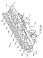
- FIG. 1 is an isometric view of an embodiment of the present invention.
- FIG. 2 is a side elevational view of an embodiment of the present invention.
- FIG. 3 is a view of an embodiment of the present invention viewing the system along line AB in FIG. 2 .
- FIG. 4 is a top view of an embodiment of the present invention.
- FIGS. 5A-5D show the displacement of a module having an array of magnets relative to the other module.
- FIGS. 6 and 7 are graphs of finite-element-analysis models of the present invention.
- FIG. 8 is a schematic of the control system for an embodiment of the invention.
- FIG. 9 is a flow diagram showing an embodiment of the invention.
- FIG. 10 is a schematic of an embodiment of the invention.
- the inventive system 100 is intended to operate in conjunction with a conventional type synchronous linear electrical machine operating as a motor or an electrodynamic brake.
- An example of such a synchronous linear electrical machine operating as a motor or an electrodynamic brake preferably comprises primary members 300 , 500 comprising arrays of at least two permanent magnets 310 - 380 , 510 - 580 of alternating polarity.
- the magnets are preferably attached to back plates 200 , 400 which are preferably mounted on primary mounting plate 11 .
- the magnets along with backplate and plates 10 comprise respective modules 1000 , 2000 .
- a synchronous linear secondary stator member (not shown) accompanies the primary members to provide the synchronous linear electrical machine operating as a motor or an electrodynamic brake.
- a stator member can be mounted on the bottom of any incoming vehicle a fin-like protrusion that passes through the air gap 40 (shown in FIG. 3 ) between primary members 300 , 500 of modules 1000 , 2000 .
- magneto-motive i.e., braking force
- This invention is concentrated on the primary members 300 , 500 movement relative to one another and therefore discussion of a secondary stator member will be minimal.
- the two primary members 300 , 500 oppose each other. It is known to those skilled in the art that if the magnets in opposing primary member arrays 300 , 500 are moved 180 electrical degrees relative to one another (as shown in FIG. 5D ), the electrodynamic brake is fully out of phase and thereby inactive. But if the magnets in the primary member arrays 300 , 500 are incrementally moved relative to one another (as shown in FIGS. 5A-5C ), the magneto-motive force created will correspond to the phase angle created by said relative movement.
- the present invention allows for the incremental movement of a primary member relative to an opposing primary member and in this way provides for a variable electrodynamic braking force.
- the invention comprises two opposing primary members 300 , 500 each comprising arrays of permanent magnets 310 - 380 , 510 - 580 .
- the first primary member 300 is preferably mounted in a stationary fashion.
- the second primary member 500 is mounted to a movable plate 10 .
- the movable plate 10 is preferably an angle weldment.
- the arrays are preferably mounted to a back plate 200 , 400 which is ferromagnetic.
- the magnetic array of the primary member 300 in the first stationarily mounted member directly opposes the magnetic array of the second primary member 500 with magnets of opposite polarity facing each other, for example magnets 310 , 320 , 330 , 340 , 350 , 360 , 370 , and 380 directly face and oppose magnets 510 , 520 , 530 , 540 , 550 , 560 , 570 , and 580 respectively.
- FIGS. 1 and 4 show the positive magnet of the stationary array 310 directly opposing negative magnet 510 of the movable array.
- a carriage 12 is affixed to the movable plate 10 and is slidably engaged with a linear bearing slide 14 .
- a bracket 16 connects the movable plate 10 to a push rod 22 , said push rod 22 being driven by a means for incremental displacement 20 .
- the means for incremental displacement 20 is preferably an optically encoded servo-motor operable to linearly displace the push rod 22 in direction A or B.
- the means for incremental displacement 20 is able to displace the push rod 22 (and therefore the movable plate 10 ) to and from a plurality points along pathway AB.
- the end points of the pathway are only limited by the length of the push rod 22 , the length of the linear slide bearing 14 , or the placement of the cushion bump stops 30 , 32 .
- the incremental displacement in the invention differs from conventional systems, which only allow for displacement to and from only a few fixed points, most often two fixed points. Incremental displacement according to the present invention allows for modules and primary members to be moved to and from anywhere along a displacement path.
- pressurized cushion bump stops 30 and 32 are affixed to the linear bearing slide 14 so as to limit the motion of the system upon contacting the bump stop supports 34 .
- the means for incremental displacement 20 displaces the second primary member 500 a selected or a predetermined distance along direction AB.
- Braking force can be varied by the amount of displacement of the second primary member 500 relative to the first 300 .
- the predetermined displacement distance is determined based on the amount of braking force that is desired to be applied to the moving object having the secondary stator member attached.
- the module 1000 can be moved relative to the stationary module 2000 a plurality of distances based on the desired braking force. To deactivate the brake completely, the secondary movable module 1000 will be moved completely out of phase as discussed above and as shown in FIG. 5D . It should be noted while that it is preferred to have one movable module and one stationary module, the invention also encompasses systems wherein both modules 1000 , 2000 , for example, are movable with respect to one another.
- FIG. 6 shows five finite-element-analysis models.
- FIG. 6 shows velocity versus time.
- FIG. 7 shows force verse versus time.
- series 1 shows as a function of velocity over time, a fully engaged operating set of finned modules without any actuation.
- Series 1 corresponds to the position of the modules shown in FIG. 1 . It can be seen that rate of velocity reduction is greatest when the brake is fully engaged.
- Series 2 shows the brake's effectiveness in reducing velocity when the primary member is moved 45 electrical degrees out of phase according to the present invention.
- Series 2 corresponds to the position of the modules shown in FIG. 5A .
- Series 2 It can be seen in Series 2 that rate of velocity reduction is lowered.
- Series 3 and 4 similarly show a decrease in the rate of reduction and corresponds to the position of the modules shown in FIGS. 5B and 5C respectively and caused by moving the member 90 and 135 electrical degrees out of phase.
- Series 5 shows a brake that is 180 degrees out of phase, which in this example was 5 linear inches of displacement of a primary member.
- Series 5 corresponds to the position of the modules shown in FIG. 5D . It can be seen that at this position, there is no reduction of velocity.
- FIG. 7 shows corresponding levels of braking force generated by the system.
- another embodiment comprises, the means for incremental displacement 20 in communication with a detection device, which detects a condition, for example, the velocity of the incoming vehicle, temperature, humidity or mass of the incoming vehicle.
- a detection device which detects a condition, for example, the velocity of the incoming vehicle, temperature, humidity or mass of the incoming vehicle.
- the velocity detection device can be of the conventional kind, for example, a set of proximity switches or photo-sensors of the conventional type in a conventional arrangement that can determine velocity.
- the velocity detection device 52 reads the velocity V of an incoming vehicle 60 and communicates that velocity to a data processor 54 .
- the data processor 54 comprises an encoded set of instructions 56 and processes the data to calculate the required displacement value DV of the movable module to achieve a desired braking force.
- the instructions 54 can be in the form of software or can be encoded on an embedded chip in the processor.
- the data processor 54 processes the data related to velocity, instructs the means for incremental displacement 20 , and in turn the push rod 22 , to move the desired distance X. In this way, the system provides a system and method that provides a braking level responsive to changes in velocity due to changes in mass, temperature, humidity, and other variables.
Abstract
Description
Claims (21)
Priority Applications (6)
| Application Number | Priority Date | Filing Date | Title |
|---|---|---|---|
| US11/058,880 US8727078B2 (en) | 2004-05-28 | 2005-02-16 | Selectively incrementally actuated linear eddy current braking system |
| EP05755481A EP1751838B1 (en) | 2004-05-28 | 2005-05-27 | Selectively incrementally actuated linear eddy current braking system |
| AU2005251181A AU2005251181A1 (en) | 2004-05-28 | 2005-05-27 | Selectively incrementally actuated linear eddy current braking system |
| PCT/US2005/018788 WO2005119889A1 (en) | 2004-05-28 | 2005-05-27 | Selectively incrementally actuated linear eddy current braking system |
| CA2568417A CA2568417C (en) | 2004-05-28 | 2005-05-27 | Selectively incrementally actuated linear eddy current braking system |
| US14/266,403 US9415693B2 (en) | 2004-05-28 | 2014-04-30 | Selectively incrementally actuated linear eddy current braking system |
Applications Claiming Priority (2)
| Application Number | Priority Date | Filing Date | Title |
|---|---|---|---|
| US57543104P | 2004-05-28 | 2004-05-28 | |
| US11/058,880 US8727078B2 (en) | 2004-05-28 | 2005-02-16 | Selectively incrementally actuated linear eddy current braking system |
Related Child Applications (1)
| Application Number | Title | Priority Date | Filing Date |
|---|---|---|---|
| US14/266,403 Continuation US9415693B2 (en) | 2004-05-28 | 2014-04-30 | Selectively incrementally actuated linear eddy current braking system |
Publications (2)
| Publication Number | Publication Date |
|---|---|
| US20050263356A1 US20050263356A1 (en) | 2005-12-01 |
| US8727078B2 true US8727078B2 (en) | 2014-05-20 |
Family
ID=35064886
Family Applications (2)
| Application Number | Title | Priority Date | Filing Date |
|---|---|---|---|
| US11/058,880 Active US8727078B2 (en) | 2004-05-28 | 2005-02-16 | Selectively incrementally actuated linear eddy current braking system |
| US14/266,403 Active US9415693B2 (en) | 2004-05-28 | 2014-04-30 | Selectively incrementally actuated linear eddy current braking system |
Family Applications After (1)
| Application Number | Title | Priority Date | Filing Date |
|---|---|---|---|
| US14/266,403 Active US9415693B2 (en) | 2004-05-28 | 2014-04-30 | Selectively incrementally actuated linear eddy current braking system |
Country Status (5)
| Country | Link |
|---|---|
| US (2) | US8727078B2 (en) |
| EP (1) | EP1751838B1 (en) |
| AU (1) | AU2005251181A1 (en) |
| CA (1) | CA2568417C (en) |
| WO (1) | WO2005119889A1 (en) |
Cited By (3)
| Publication number | Priority date | Publication date | Assignee | Title |
|---|---|---|---|---|
| US20140231193A1 (en) * | 2004-05-28 | 2014-08-21 | Velocity Magnetics, Inc. | Selectively incrementally actuated linear eddy current braking system |
| US20150091478A1 (en) * | 2013-10-02 | 2015-04-02 | Velocity Magnetics, Inc. | Solid state energy storage and management system |
| US11496075B2 (en) | 2017-10-11 | 2022-11-08 | Velocity Magnetics, Inc. | Using linear synchronous motors for retarding linear motion and conveying systems |
Families Citing this family (16)
| Publication number | Priority date | Publication date | Assignee | Title |
|---|---|---|---|---|
| TW200918380A (en) * | 2007-04-03 | 2009-05-01 | Bombardier Transp Gmbh | Track brake controller |
| NZ575464A (en) | 2009-03-10 | 2010-07-30 | Holmes Solutions Ltd | Improvements in and relating to braking mechanisms |
| CN102167056B (en) * | 2011-04-07 | 2013-05-08 | 江苏大学 | Linear permanent magnetic rail brake |
| NZ619034A (en) | 2013-12-16 | 2015-03-27 | Eddy Current Ltd Partnership | An assembly to control relative speed of movement between parts |
| SG11201701192UA (en) | 2014-08-18 | 2017-03-30 | Eddy Current Ltd Partnership | Tuning of a kinematic relationship between members |
| MX364898B (en) | 2014-08-18 | 2019-05-13 | Eddy Current Lp | Latching devices. |
| CN111817532B (en) | 2014-08-18 | 2023-07-28 | 涡流有限合伙公司 | Adjustment of the movement relationship between components |
| US10035421B2 (en) | 2014-08-20 | 2018-07-31 | Hi Tech Llc | Eddy current braking device for linear systems |
| US11050336B2 (en) | 2014-12-04 | 2021-06-29 | Eddy Current Limited Partnership | Methods of altering eddy current interactions |
| EP3226978A4 (en) | 2014-12-04 | 2018-05-02 | Eddy Current Limited Partnership | Latch activation between elements |
| AU2015355674A1 (en) | 2014-12-04 | 2017-06-08 | Eddy Current Limited Partnership | Eddy current brake configurations |
| EP3226980B1 (en) | 2014-12-04 | 2023-05-10 | Eddy Current Limited Partnership | Energy absorbing apparatus |
| US10693360B2 (en) | 2014-12-04 | 2020-06-23 | Eddy Current Limited Partnership | Transmissions incorporating eddy current braking |
| CN104753311B (en) * | 2015-04-24 | 2017-03-01 | 哈尔滨工业大学 | Long-stroke permanent magnet rectilinear vortex brake |
| CA2984755C (en) | 2015-05-04 | 2023-10-03 | Vekoma Rides Engineering B.V. | Amusement ride with speed trim system |
| BR122021013798B1 (en) | 2015-12-18 | 2023-04-18 | Eddy Current Limited Partnership | VARIABLE OPERATING CONTROL MECHANISM FOR MOTOR SYSTEM |
Citations (32)
| Publication number | Priority date | Publication date | Assignee | Title |
|---|---|---|---|---|
| GB433408A (en) | 1933-12-07 | 1935-08-14 | Raoul Sarazin | Improvements in electrical devices for the absorption of mechanical energy |
| DE1259453B (en) | 1963-09-26 | 1968-01-25 | Ziehl Abegg O H G | Variable speed asynchronous brake motor with squirrel cage for high switching frequency |
| US3794425A (en) * | 1972-08-22 | 1974-02-26 | Shell Oil Co | Scanning infrared spectroscopic analyzer using rotating variable filter |
| GB1456366A (en) | 1972-12-14 | 1976-11-24 | Hawker Siddeley Dynamics Ltd | Linear displacement devices |
| JPS57151263A (en) | 1981-03-13 | 1982-09-18 | Mitsubishi Electric Corp | Eddy current generating rotary disc |
| JPS59172967A (en) | 1983-03-18 | 1984-09-29 | Toshiba Corp | Eddy current brake device |
| US4486638A (en) | 1981-10-16 | 1984-12-04 | La Material Magnetique | Device for converting rotational kinetic energy to heat by generating eddy currents |
| US4767954A (en) | 1986-04-11 | 1988-08-30 | Compact Spindle Bearing Corporation | Solid state commutated linear motor with an ironless multiphase armature |
| US4857786A (en) * | 1987-04-06 | 1989-08-15 | Hitachi, Ltd. | Structure of stepping motor and method of driving the stepping motor |
| DE4137201A1 (en) | 1991-11-12 | 1993-05-13 | Intrasys Gmbh | LINEAR MOTOR OR GENERATOR AND STATOR HERE |
| US5479145A (en) | 1993-09-01 | 1995-12-26 | Northrop Grumman Corporation | Superconducting electromagnet for levitation and propulsion of a maglev vehicle |
| US5757091A (en) | 1995-07-03 | 1998-05-26 | Fanuc Ltd. | Permanent magnet field pole for linear motor |
| US5952742A (en) | 1995-02-03 | 1999-09-14 | Krauss-Maffei Ag | Synchronous linear motor with improved means for positioning and fastening permanent magnets |
| EP0959549A1 (en) | 1998-05-22 | 1999-11-24 | Northmag B.V. | Brushless permanent magnet electric motor |
| DE19817233C1 (en) | 1998-04-17 | 2000-01-05 | Knorr Bremse Systeme | Method for controlling and / or regulating an eddy current brake |
| US6062350A (en) | 1995-04-13 | 2000-05-16 | Alfons Saiko | Braking system for an amusement device |
| US6253887B1 (en) * | 1998-05-22 | 2001-07-03 | Daimlerchrysler Ag | Method and system for braking a vehicle |
| US20010018641A1 (en) * | 1998-08-20 | 2001-08-30 | Honda Giken Kogyo Kabushiki Kaisha | Safety running system for vehicle |
| US6293376B1 (en) | 1999-11-22 | 2001-09-25 | Magnetar Technologies Ltd | Apparatus including eddy current braking system |
| US6326708B1 (en) | 1999-07-06 | 2001-12-04 | Nippon Thompson Co., Ltd. | Slider unit with built-in moving-coil linear motor |
| US20020003510A1 (en) * | 1998-01-16 | 2002-01-10 | Tetsu Shigetomi | Image display apparatus and method for vehicle |
| WO2002007291A1 (en) | 2000-07-17 | 2002-01-24 | Inventio Ag | Secondary part of a linear motor and method for producing the same |
| US6361268B1 (en) * | 1999-06-21 | 2002-03-26 | Sri International | Frictionless transport apparatus and method |
| US6412611B1 (en) | 2000-07-17 | 2002-07-02 | Magnetar Technologies, Ltd | Eddy current brake system with dual use conductor fin |
| US6417584B1 (en) | 1998-02-26 | 2002-07-09 | Anorad Corporation | Magnet configuration for a linear motor |
| JP2002352539A (en) * | 2001-05-23 | 2002-12-06 | Hitachi Ltd | Magnetic disk storage device and method for controlling the same device |
| US6523650B1 (en) | 2000-02-15 | 2003-02-25 | Magnetar Technologies, Inc. | Permanent magnet eddy brake with flux-steering poles |
| DE20119119U1 (en) | 2001-11-23 | 2003-04-10 | Rosner Peter | Popular amusement device with switchable eddy current brake |
| US6633217B2 (en) * | 2001-06-29 | 2003-10-14 | The Regents Of The University Of California | Inductrack magnet configuration |
| US6703754B1 (en) | 2001-10-01 | 2004-03-09 | Ametek, Inc. | Electric motor and brush retaining assembly |
| US20040233417A1 (en) * | 2003-05-20 | 2004-11-25 | Nissan Motor Co., Ltd. | Vehicle external recognition system and related method |
| US6918469B1 (en) | 2000-02-15 | 2005-07-19 | Magnetar Technologies, Inc. | Curvilinear eddy current braking apparatus |
Family Cites Families (3)
| Publication number | Priority date | Publication date | Assignee | Title |
|---|---|---|---|---|
| US5239331A (en) * | 1985-12-11 | 1993-08-24 | Canon Kabushiki Kaisha | Brake device for motor in camera |
| US6155976A (en) * | 1997-03-14 | 2000-12-05 | Nims, Inc. | Reciprocating movement platform for shifting subject to and fro in headwards-footwards direction |
| US8727078B2 (en) | 2004-05-28 | 2014-05-20 | Velocity Magnetics, Inc. | Selectively incrementally actuated linear eddy current braking system |
-
2005
- 2005-02-16 US US11/058,880 patent/US8727078B2/en active Active
- 2005-05-27 EP EP05755481A patent/EP1751838B1/en active Active
- 2005-05-27 WO PCT/US2005/018788 patent/WO2005119889A1/en not_active Application Discontinuation
- 2005-05-27 AU AU2005251181A patent/AU2005251181A1/en not_active Abandoned
- 2005-05-27 CA CA2568417A patent/CA2568417C/en active Active
-
2014
- 2014-04-30 US US14/266,403 patent/US9415693B2/en active Active
Patent Citations (35)
| Publication number | Priority date | Publication date | Assignee | Title |
|---|---|---|---|---|
| GB433408A (en) | 1933-12-07 | 1935-08-14 | Raoul Sarazin | Improvements in electrical devices for the absorption of mechanical energy |
| DE1259453B (en) | 1963-09-26 | 1968-01-25 | Ziehl Abegg O H G | Variable speed asynchronous brake motor with squirrel cage for high switching frequency |
| US3794425A (en) * | 1972-08-22 | 1974-02-26 | Shell Oil Co | Scanning infrared spectroscopic analyzer using rotating variable filter |
| GB1456366A (en) | 1972-12-14 | 1976-11-24 | Hawker Siddeley Dynamics Ltd | Linear displacement devices |
| JPS57151263A (en) | 1981-03-13 | 1982-09-18 | Mitsubishi Electric Corp | Eddy current generating rotary disc |
| US4486638A (en) | 1981-10-16 | 1984-12-04 | La Material Magnetique | Device for converting rotational kinetic energy to heat by generating eddy currents |
| JPS59172967A (en) | 1983-03-18 | 1984-09-29 | Toshiba Corp | Eddy current brake device |
| US4767954A (en) | 1986-04-11 | 1988-08-30 | Compact Spindle Bearing Corporation | Solid state commutated linear motor with an ironless multiphase armature |
| US4857786A (en) * | 1987-04-06 | 1989-08-15 | Hitachi, Ltd. | Structure of stepping motor and method of driving the stepping motor |
| DE4137201A1 (en) | 1991-11-12 | 1993-05-13 | Intrasys Gmbh | LINEAR MOTOR OR GENERATOR AND STATOR HERE |
| US5479145A (en) | 1993-09-01 | 1995-12-26 | Northrop Grumman Corporation | Superconducting electromagnet for levitation and propulsion of a maglev vehicle |
| US5952742A (en) | 1995-02-03 | 1999-09-14 | Krauss-Maffei Ag | Synchronous linear motor with improved means for positioning and fastening permanent magnets |
| US6062350A (en) | 1995-04-13 | 2000-05-16 | Alfons Saiko | Braking system for an amusement device |
| US5757091A (en) | 1995-07-03 | 1998-05-26 | Fanuc Ltd. | Permanent magnet field pole for linear motor |
| US20020003510A1 (en) * | 1998-01-16 | 2002-01-10 | Tetsu Shigetomi | Image display apparatus and method for vehicle |
| US6417584B1 (en) | 1998-02-26 | 2002-07-09 | Anorad Corporation | Magnet configuration for a linear motor |
| DE19817233C1 (en) | 1998-04-17 | 2000-01-05 | Knorr Bremse Systeme | Method for controlling and / or regulating an eddy current brake |
| EP0959549A1 (en) | 1998-05-22 | 1999-11-24 | Northmag B.V. | Brushless permanent magnet electric motor |
| US6253887B1 (en) * | 1998-05-22 | 2001-07-03 | Daimlerchrysler Ag | Method and system for braking a vehicle |
| US20010018641A1 (en) * | 1998-08-20 | 2001-08-30 | Honda Giken Kogyo Kabushiki Kaisha | Safety running system for vehicle |
| US6361268B1 (en) * | 1999-06-21 | 2002-03-26 | Sri International | Frictionless transport apparatus and method |
| US6326708B1 (en) | 1999-07-06 | 2001-12-04 | Nippon Thompson Co., Ltd. | Slider unit with built-in moving-coil linear motor |
| US6293376B1 (en) | 1999-11-22 | 2001-09-25 | Magnetar Technologies Ltd | Apparatus including eddy current braking system |
| US6659237B1 (en) | 1999-11-22 | 2003-12-09 | Magnetar Technologies, Ltd. | Eddy current brake |
| US6533083B1 (en) | 2000-02-15 | 2003-03-18 | Magnetar Technologies, Inc | Eddy current braking apparatus |
| US6918469B1 (en) | 2000-02-15 | 2005-07-19 | Magnetar Technologies, Inc. | Curvilinear eddy current braking apparatus |
| US6523650B1 (en) | 2000-02-15 | 2003-02-25 | Magnetar Technologies, Inc. | Permanent magnet eddy brake with flux-steering poles |
| WO2002007291A1 (en) | 2000-07-17 | 2002-01-24 | Inventio Ag | Secondary part of a linear motor and method for producing the same |
| US6412611B1 (en) | 2000-07-17 | 2002-07-02 | Magnetar Technologies, Ltd | Eddy current brake system with dual use conductor fin |
| JP2002352539A (en) * | 2001-05-23 | 2002-12-06 | Hitachi Ltd | Magnetic disk storage device and method for controlling the same device |
| US6633217B2 (en) * | 2001-06-29 | 2003-10-14 | The Regents Of The University Of California | Inductrack magnet configuration |
| US6703754B1 (en) | 2001-10-01 | 2004-03-09 | Ametek, Inc. | Electric motor and brush retaining assembly |
| US20040262103A1 (en) * | 2001-11-23 | 2004-12-30 | Peter Rosner | Popular amusement device with switchable eddy-current brake |
| DE20119119U1 (en) | 2001-11-23 | 2003-04-10 | Rosner Peter | Popular amusement device with switchable eddy current brake |
| US20040233417A1 (en) * | 2003-05-20 | 2004-11-25 | Nissan Motor Co., Ltd. | Vehicle external recognition system and related method |
Cited By (9)
| Publication number | Priority date | Publication date | Assignee | Title |
|---|---|---|---|---|
| US20140231193A1 (en) * | 2004-05-28 | 2014-08-21 | Velocity Magnetics, Inc. | Selectively incrementally actuated linear eddy current braking system |
| US9415693B2 (en) * | 2004-05-28 | 2016-08-16 | Velocity Magnetics, Inc. | Selectively incrementally actuated linear eddy current braking system |
| US20150091478A1 (en) * | 2013-10-02 | 2015-04-02 | Velocity Magnetics, Inc. | Solid state energy storage and management system |
| US10046644B2 (en) * | 2013-10-02 | 2018-08-14 | Velocity Magnetics, Inc. | Solid state energy storage and management system |
| US20180345797A1 (en) * | 2013-10-02 | 2018-12-06 | Velocity Magnetics, Inc. | Solid State Energy Storage and Management System |
| US11052766B2 (en) * | 2013-10-02 | 2021-07-06 | Velocity Magnetics, Inc. | Solid state energy storage and management system |
| US11602996B2 (en) | 2013-10-02 | 2023-03-14 | Velocity Magnetics, Inc. | Solid state energy storage and management system |
| EP4178074A1 (en) | 2013-10-02 | 2023-05-10 | Velocity Magnetics, Inc. | Capacitive energy storage and management system |
| US11496075B2 (en) | 2017-10-11 | 2022-11-08 | Velocity Magnetics, Inc. | Using linear synchronous motors for retarding linear motion and conveying systems |
Also Published As
| Publication number | Publication date |
|---|---|
| EP1751838A1 (en) | 2007-02-14 |
| WO2005119889A1 (en) | 2005-12-15 |
| EP1751838B1 (en) | 2012-12-19 |
| US9415693B2 (en) | 2016-08-16 |
| CA2568417A1 (en) | 2005-12-15 |
| US20140231193A1 (en) | 2014-08-21 |
| US20050263356A1 (en) | 2005-12-01 |
| CA2568417C (en) | 2015-02-24 |
| AU2005251181A1 (en) | 2005-12-15 |
Similar Documents
| Publication | Publication Date | Title |
|---|---|---|
| US8727078B2 (en) | Selectively incrementally actuated linear eddy current braking system | |
| US10661399B2 (en) | Single-drive rigid-flexible coupling precision motion platform and realization method and application thereof | |
| WO2001038123B1 (en) | Apparatus including eddy current braking system | |
| EP1193847B1 (en) | Slider unit with built-in moving-coil linear motor | |
| WO2007108586A1 (en) | System of railway vehicle using linear motor and non-contact electric power supply system | |
| GB2323716A (en) | Position detector location in a linear actuator | |
| US5245232A (en) | Linear actuator | |
| US7626348B2 (en) | Linear motor door actuator | |
| CN100439741C (en) | Brake apparatus for linear motor and method for positioning movable section of linear motor | |
| CN108025647A (en) | Operating unit for vehicle | |
| EP3471996B1 (en) | Magnetic suspension for a vehicle | |
| AU7923200A (en) | System for controlling movements of a load lifting device | |
| CA2548861C (en) | Linear motor door actuator | |
| US7453172B2 (en) | Linear slide apparatus | |
| EP0353074B1 (en) | Step linear actuator | |
| EP3918280B1 (en) | Position sensor for long stroke linear permanent magnet motor | |
| CN204179915U (en) | Controlled displacement feeding drive system | |
| KR102474188B1 (en) | Mulberry cotton manufacturing apparatus | |
| KR100769047B1 (en) | Linear motor | |
| JP3191867B2 (en) | Optical head transport mechanism | |
| CN102817913A (en) | Air-floatation follow-up device capable of eliminating inertia force influence | |
| CN205363277U (en) | Miniature lathe guide rail control system of permanent magnetism suspension | |
| JP2001160481A (en) | Electromagnetic induction heating device | |
| JP2005117831A (en) | Moving magnet linear actuator | |
| CN115602586A (en) | Pushing device and packaging equipment |
Legal Events
| Date | Code | Title | Description |
|---|---|---|---|
| AS | Assignment |
Owner name: VELOCITY MAGNETICS, INC., PENNSYLVANIA Free format text: ASSIGNMENT OF ASSIGNORS INTEREST;ASSIGNORS:MARZANO, MR. DOMENIC P.;GUSTASON, MR. MICHAEL;WALT DISNEY IMAGINEERING BY PETER STEINMAN, VICE PRESIDENT AND GENERAL COUNSEL;REEL/FRAME:015716/0340;SIGNING DATES FROM 20050127 TO 20050204 Owner name: VELOCITY MAGNETICS, INC., PENNSYLVANIA Free format text: ASSIGNMENT OF ASSIGNORS INTEREST;ASSIGNORS:MARZANO, MR. DOMENIC P.;GUSTASON, MR. MICHAEL;WALT DISNEY IMAGINEERING BY PETER STEINMAN, VICE PRESIDENT AND GENERAL COUNSEL;SIGNING DATES FROM 20050127 TO 20050204;REEL/FRAME:015716/0340 |
|
| STCF | Information on status: patent grant |
Free format text: PATENTED CASE |
|
| MAFP | Maintenance fee payment |
Free format text: PAYMENT OF MAINTENANCE FEE, 4TH YR, SMALL ENTITY (ORIGINAL EVENT CODE: M2551) Year of fee payment: 4 |
|
| MAFP | Maintenance fee payment |
Free format text: PAYMENT OF MAINTENANCE FEE, 8TH YR, SMALL ENTITY (ORIGINAL EVENT CODE: M2552); ENTITY STATUS OF PATENT OWNER: SMALL ENTITY Year of fee payment: 8 |