US8723398B2 - Piezoelectric energy harvesting apparatus - Google Patents
Piezoelectric energy harvesting apparatus Download PDFInfo
- Publication number
- US8723398B2 US8723398B2 US13/303,179 US201113303179A US8723398B2 US 8723398 B2 US8723398 B2 US 8723398B2 US 201113303179 A US201113303179 A US 201113303179A US 8723398 B2 US8723398 B2 US 8723398B2
- Authority
- US
- United States
- Prior art keywords
- energy harvesting
- peh
- piezoelectric energy
- piezoelectric
- array
- Prior art date
- Legal status (The legal status is an assumption and is not a legal conclusion. Google has not performed a legal analysis and makes no representation as to the accuracy of the status listed.)
- Expired - Fee Related, expires
Links
- 238000003306 harvesting Methods 0.000 title claims abstract description 44
- 239000002184 metal Substances 0.000 claims description 11
- 229920001410 Microfiber Polymers 0.000 claims description 2
- 239000002131 composite material Substances 0.000 claims description 2
- 239000003658 microfiber Substances 0.000 claims description 2
- 229920006395 saturated elastomer Polymers 0.000 claims description 2
- 230000008878 coupling Effects 0.000 description 8
- 238000010168 coupling process Methods 0.000 description 8
- 238000005859 coupling reaction Methods 0.000 description 8
- 238000000034 method Methods 0.000 description 7
- 230000007613 environmental effect Effects 0.000 description 6
- 238000003491 array Methods 0.000 description 5
- 230000008859 change Effects 0.000 description 5
- 230000002093 peripheral effect Effects 0.000 description 5
- 238000006073 displacement reaction Methods 0.000 description 4
- 238000004519 manufacturing process Methods 0.000 description 4
- 239000000463 material Substances 0.000 description 3
- 230000003213 activating effect Effects 0.000 description 2
- 239000000919 ceramic Substances 0.000 description 2
- 239000013078 crystal Substances 0.000 description 2
- 238000010586 diagram Methods 0.000 description 2
- 230000000694 effects Effects 0.000 description 2
- 230000003321 amplification Effects 0.000 description 1
- 239000003990 capacitor Substances 0.000 description 1
- 238000010276 construction Methods 0.000 description 1
- 230000007423 decrease Effects 0.000 description 1
- 230000003247 decreasing effect Effects 0.000 description 1
- 230000005611 electricity Effects 0.000 description 1
- 230000004048 modification Effects 0.000 description 1
- 238000012986 modification Methods 0.000 description 1
- 238000003199 nucleic acid amplification method Methods 0.000 description 1
- 230000010287 polarization Effects 0.000 description 1
- 230000008569 process Effects 0.000 description 1
- 230000035939 shock Effects 0.000 description 1
- 238000003860 storage Methods 0.000 description 1
Images


Classifications
-
- H—ELECTRICITY
- H02—GENERATION; CONVERSION OR DISTRIBUTION OF ELECTRIC POWER
- H02N—ELECTRIC MACHINES NOT OTHERWISE PROVIDED FOR
- H02N2/00—Electric machines in general using piezoelectric effect, electrostriction or magnetostriction
- H02N2/18—Electric machines in general using piezoelectric effect, electrostriction or magnetostriction producing electrical output from mechanical input, e.g. generators
- H02N2/186—Vibration harvesters
- H02N2/188—Vibration harvesters adapted for resonant operation
-
- H—ELECTRICITY
- H02—GENERATION; CONVERSION OR DISTRIBUTION OF ELECTRIC POWER
- H02N—ELECTRIC MACHINES NOT OTHERWISE PROVIDED FOR
- H02N2/00—Electric machines in general using piezoelectric effect, electrostriction or magnetostriction
- H02N2/18—Electric machines in general using piezoelectric effect, electrostriction or magnetostriction producing electrical output from mechanical input, e.g. generators
- H02N2/181—Circuits; Control arrangements or methods
Definitions
- the present disclosure relates to a piezoelectric energy harvesting apparatus, and more particularly, to a piezoelectric energy harvesting apparatus that can improve output by fitting the resonance frequency of a piezoelectric energy harvesting array to the frequency of an environmental vibration.
- a piezoelectric energy harvesting device (hereafter, referred to as a “PEH device”) generates the largest electric energy at the resonance frequency, with amplification of the displacement, when the frequency of the environmental vibration and the resonance frequency of the PEH device agree with each other.
- the voltage generated by the PEH device is outputted in the AC (Alternating Current) type.
- a rectifier is used to convert the AC voltage into the DC voltage.
- the rectifier is composed of four or two diodes, in a full-bridge or half-bridge type.
- a capacitor for reducing ripple of the DC voltage is connected to the rear end of the rectifier.
- the DC voltage is used to charge another supercapacitor or a battery, or activate an IC etc. Electric energy that is obtained from small vibrations generated in the peripheral environment is, however, not sufficient as power for activating an IC because the magnitudes are too small. Therefore, a method of increasing output by optimizing the size or the shape of the PEH device or using a multilayer has been researched.
- a piezoelectric ceramic device has a brittle property, such that it is vulnerable to shock etc. and is limited in increasing the size of the device.
- Using the multilayer is not suitable for manufacturing the PEH device, because the manufacturing processes are not yet established.
- As another method of increasing the output of the PEH device there is a method using single crystals having high coupling efficiency and a large piezoelectric constant, which requires very difficult process for manufacture a multilayer.
- a method of improving output, using piezoelectric energy harvesting arrays (hereafter, referred to as ‘PEH arrays’) can be proposed.
- a method that uses a tip mass at the end of a cantilever after optimizing the shape or the size of a single PEH device itself is generally used to fit the resonance frequency of the PEH device to the frequency of an environmental vibration (for example, 1 to 120 Hz).
- the resonance frequencies are determined by an effective electro-mechanical coupling constant.
- a resistor R is connected to the end of the PEH device, with a low vibration applied, and the current flowing through the connected resistor R is measured, or the voltages at both ends of the resistor are measured. Since the frequency where the maximum output is generated changes between the sc resonance frequency and the oc resonance frequency, in accordance with the value of the resistor R, the resonance frequency of the single PEH device can be easily measured.
- the sc resonance frequency and the oc resonance frequency of the PEH array depend on the mechanical state as well as the electric connection states, the electric properties of the PEH array are measured, with the resonance frequency of the single PEH device made fit the frequency of the environmental vibration, after the PEH array is manufactured. In this case, a desired output cannot be achieved due to output saturation, even if the number of PEH devices is increased.
- the present disclosure has been made in an effort to provide a piezoelectric energy harvesting apparatus that can reduce an electric loss by fitting the resonance frequency of a piezoelectric energy harvesting array to the frequency of an environmental vibration, increase the output current by generating output electricity that is proportionate to an increase in the number of piezoelectric energy harvesting devices, and rapidly charge a supercapacitor or a battery.
- An exemplary embodiment of the present disclosure provides a piezoelectric energy harvesting apparatus including: a piezoelectric energy harvesting array that includes a plurality of piezoelectric energy harvesting devices converting an external vibration into electric energy; a plurality of switches that are connected in series to the piezoelectric energy harvesting devices, respectively, and fit the resonance frequency of the piezoelectric energy harvesting array to the frequency of the external vibration by adjusting the resonance frequencies of the piezoelectric energy harvesting devices through the operation of the switches; and at least one or more rectifiers that convert alternating voltage outputted from the piezoelectric energy harvesting array into direct voltage.
- the piezoelectric energy harvesting apparatus can be used in the devices constituting a wireless sensor network, which is require to be charged by themselves due to high output, as power suppliers.
- FIG. 1 is a block configuration diagram showing the configuration of a piezoelectric energy harvesting apparatus according to an exemplary embodiment of the present disclosure.
- FIG. 2 is a cross-sectional view of a PEH device according to an exemplary embodiment of the present disclosure.
- FIG. 3 is a graph showing output current/voltage at the sc resonance frequency of individual PEH devices.
- FIG. 4 is a graph showing output current/voltage at the oc resonance frequency of individual PEH devices.
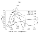
- FIG. 5 is a graph showing output current/voltage at the resonance frequency of a PEH array according to an exemplary embodiment of the present disclosure.
- piezoelectric energy harvesting devices (hereafter, referred to as ‘PEH devices’) are classified into a piezoelectric monomorph composed of a single piezoelectric layer that generates electric output and a non-piezoelectric layer that reinforces the brittle characteristic of the piezoelectric layer and a piezoelectric bimorph in which piezoelectric layers are stacked at both sides of the non-piezoelectric layer.
- PEH devices there is a multilayer PEH device in which several layers are stacked, instead of two piezoelectric layers.
- two piezoelectric layers can be connected in series or in parallel, depending on the polarization direction of two piezoelectric layers.
- the output current is high, while in the series connection, the output voltage is high.
- the output power is not influenced by the shape of the wire connection.
- the optimum resistance that generates the maximum output power is influenced by the connection status of wires, and accordingly, the resonance frequency of the PET device changes. Since the optimum resistance that generates the maximum power output is larger in the series connection than the parallel connection, the output voltage and the output current are produced inversely proportionate. That is, the parallel connection has a low electric impedance, whereas the series connection shows high electric impedance.
- a supercapacitor or a battery Since a supercapacitor or a battery is considerably influenced by the magnitude of the current, they may be charged in the parallel connection with high output current.
- the output power/current of the PEH device can be maximized by fitting the own frequency to the frequency of a peripheral vibration. This frequency is called the resonance frequency of the PEH device.
- the frequency measured with two wires connected (R ⁇ 0) is called a resonance frequency in a short-circuit state (hereafter, referred to as ‘sc resonance frequency) and the frequency measured with two wires opened (R ⁇ ) is called a resonance frequency in an open-circuit state (hereafter, referred to as ‘oc resonance frequency’).
- the PEH device Similar to the wire connection of the piezoelectric bimorph, the PEH device outputs high current when vibrating at the sc resonance frequency, and outputs high voltage when vibrating at the oc resonance frequency. That is, when the PEH device is in the sc state, the maximum current is generated.
- PH array piezoelectric energy harvesting arrays
- the electric properties of the PEH array are measured, with the resonance frequency of the single PEH device made fit the frequencies of the peripheral vibrations, after the PEH array is manufactured. In this case, a desired output cannot be achieved due to output saturation, even if the number of PEH devices is increased.
- the mechanical properties of the PEH array that is, displacement of the PEH array which is caused by a vibration decreases and the decreased displacement reduces the electric output.
- an effective capacitance increases in proportion to the number of the PEH devices due to the parallel connection of the capacitances that the piezoelectric materials have (that is, the piezoelectric materials can be shown by an electric parallel connection state of a current supply and a capacitance).
- a change in effective capacitance has an effect on the electric properties of the PEH array. This is in close connection with the effective electro-mechanical coupling constant of the piezoelectric device.
- the resonance frequency of a piezoelectric device is divided by the effective electro-mechanical coupling constant.
- Keq mechanical effective stiffness of a piezoelectric device
- Meq effective mass
- ⁇ an effective electro-mechanical coupling constant
- a change in effective electro-mechanical coupling constant of a piezoelectric device has the largest effect on not only the frequency, but the electric output, such that output saturation is caused, even though the PEH array increases in the PEH arrays, even if electric output is generated at the resonance frequency in the PEH device.
- an exemplary embodiment of the present disclosure provides a piezoelectric energy harvesting apparatus that can fit the resonance frequency of the PEH array to the frequency of a peripheral vibration.
- FIG. 1 is a block configuration diagram showing the configuration of a piezoelectric energy harvesting apparatus according to an exemplary embodiment of the present disclosure.
- a piezoelectric energy harvesting apparatus includes a PEH array 110 , a plurality of switches 120 , and a rectifier 130 .
- a PEH array 110 includes four PEH devices 112 for the convenience of description in the exemplary embodiment of the present disclosure, PEH array 110 is not limited thereto and may include at least two or more PEH devices 112 , if necessary.
- PEH array 110 includes a plurality of PEH devices 112 that change an external vibration into electric energy.
- PEH devices 112 may include a vibration base 210 , a metal core 220 , a piezoelectric layer 230 , and a tip mass 240 and the components of PEH device 112 are described in detail with reference to FIG. 2 .
- Switches 120 are connected in series to PEH devices 112 , respectively, the resonance frequencies of PEH devices 112 are adjusted by operating the switches, such that resonance frequency of PEH array 110 is fitted to the frequency of an external vibration.
- the output voltage of PEH array 110 becomes the maximum, when all of switches 120 are turned on. Further, at least one or more switches in switches 120 may be turned off such that the output current of PEH array 110 is not saturated.
- Rectifier 130 converts the alternating voltage outputted from PEH array 110 into direct voltage and stores the direct voltage in a storage device 140 .
- FIG. 2 is a cross-sectional view of a PEH device according to an exemplary embodiment of the present disclosure.
- PEH device 112 includes a vibration base 210 , a metal core 220 , a piezoelectric layer 230 , and a tip mass 240 .
- Vibration base 210 functions as a fixing end for PEH device 112 .
- metal core 220 is fixed to vibration base 210 and tip mass 240 is connected to the other end.
- a groove may be longitudinally formed on the top of metal core 220 , as a structure for increasing the displacement of metal core 220 .
- Piezoelectric layer 230 may be formed on or under the metal core 220 and may include a PZT, a PMN-PT, a PZN-PT, a PMN-PZT, and a MFC (micro-fiber composite). Further, it is possible to prevent breaking due to physical stress by forming piezoelectric layer 230 apart from vibration base 210 .
- Tip mass 240 is a weight for applying vibration to PEH device 112 and connected to the other end of metal core 220 . Weight of tip mass 240 may be changed to change the vibration frequency of PEH device 112 .
- FIG. 3 is a graph showing output current/voltage at the sc resonance frequency of individual PEH devices and FIG. 4 is a graph showing output current/voltage at the oc resonance frequency of individual PEH devices.
- ‘ 310 ’ represents the output current of the PEH devices at the sc resonance frequency and ‘ 320 ’ represents the output voltage of the PEH devices at the sc resonance frequency.
- ‘ 410 ’ represents the output current of the PEH devices at the oc resonance frequency and ‘ 420 ’ represents the output voltage of the PEH devices at the oc resonance frequency.
- the output current of the PEH devices becomes the maximum at the sc resonance frequency
- the output voltage of the PEH devices becomes the maximum at the oc resonance frequency
- FIG. 5 is a graph showing output current/voltage at the resonance frequency of a PEH array according to an exemplary embodiment of the present disclosure.
- ‘ 510 ’ represents the output current of the PEH devices at the resonance frequency and ‘ 520 ’ represents the output voltage of the PEH devices at the resonance frequency.
- the existing PET arrays had a limit in increasing the output current due to output saturation, even though the number of PEH devices is increased.
- the PEH array according to the exemplary embodiment of the present disclosure does not causes output saturation, such that it can be seen that the output current increases in proportion to the number of PEH devices.
Abstract
Description
[Formula 1]
ωsc=√{square root over (K eq /M eq)},ωoc=ωsc·√{square root over (1+κ)}
Claims (7)
Applications Claiming Priority (2)
| Application Number | Priority Date | Filing Date | Title |
|---|---|---|---|
| KR1020100129936A KR101727252B1 (en) | 2010-12-17 | 2010-12-17 | Piezoelectric Energy Harvesting Apparatus |
| KR10-2010-0129936 | 2010-12-17 |
Publications (2)
| Publication Number | Publication Date |
|---|---|
| US20120153773A1 US20120153773A1 (en) | 2012-06-21 |
| US8723398B2 true US8723398B2 (en) | 2014-05-13 |
Family
ID=46233457
Family Applications (1)
| Application Number | Title | Priority Date | Filing Date |
|---|---|---|---|
| US13/303,179 Expired - Fee Related US8723398B2 (en) | 2010-12-17 | 2011-11-23 | Piezoelectric energy harvesting apparatus |
Country Status (2)
| Country | Link |
|---|---|
| US (1) | US8723398B2 (en) |
| KR (1) | KR101727252B1 (en) |
Cited By (3)
| Publication number | Priority date | Publication date | Assignee | Title |
|---|---|---|---|---|
| US9647579B2 (en) | 2014-09-11 | 2017-05-09 | Electronics And Telecommunications Research Institute | Energy harvesting device, method for manufacturing the same, and wireless device including the same |
| US20210265556A1 (en) * | 2020-02-26 | 2021-08-26 | Stmicroelectronics S.R.L. | Micro electro mechanical system and manufacturing method thereof |
| US11508900B2 (en) | 2019-11-26 | 2022-11-22 | The Chinese University Of Hong Kong | Human joint energy harvesting apparatus and wearable electronic device comprising the same |
Families Citing this family (10)
| Publication number | Priority date | Publication date | Assignee | Title |
|---|---|---|---|---|
| US9595893B2 (en) * | 2012-07-23 | 2017-03-14 | Schlumberger Technology Corporation | Non-stationary multi-frequency vibration energy harvesting with tunable electrical impedance |
| US9837933B2 (en) | 2013-06-28 | 2017-12-05 | Samsung Electronics Co., Ltd. | Energy harvester using mass and mobile device including the energy harvester |
| US9444031B2 (en) | 2013-06-28 | 2016-09-13 | Samsung Electronics Co., Ltd. | Energy harvester using mass and mobile device including the energy harvester |
| WO2017099458A1 (en) * | 2015-12-08 | 2017-06-15 | 김홍섭 | Vibration piezoelectric sensor and device for checking motor operating state by using same |
| FR3069395A1 (en) * | 2017-07-18 | 2019-01-25 | Commissariat A L'energie Atomique Et Aux Energies Alternatives | PIEZOELECTRIC GENERATOR |
| ES2707207A1 (en) * | 2017-10-02 | 2019-04-02 | Frau Pedro Sabater | DEVICE FOR THE RECOVERY OF ENERGY PRODUCED BY A FORCE (Machine-translation by Google Translate, not legally binding) |
| CN108459176B (en) * | 2018-04-12 | 2023-11-07 | 常州机电职业技术学院 | Piezoelectric energy collection structure based on wind induced vibration and self-powered wind speed measuring device and method |
| KR102241424B1 (en) | 2019-04-09 | 2021-04-20 | 주식회사 커널로그 | Energy harvesting-based controller device |
| KR20210026910A (en) | 2019-09-02 | 2021-03-10 | 삼성전자주식회사 | Method and device for providing power generated from external energy signal |
| NL2026885B1 (en) * | 2020-11-12 | 2022-06-30 | Stem Tech | Ixora Holding B V | System for converting vibrations, in particular sound vibrations into usable electric energy |
Citations (9)
| Publication number | Priority date | Publication date | Assignee | Title |
|---|---|---|---|---|
| US5801475A (en) * | 1993-09-30 | 1998-09-01 | Mitsuteru Kimura | Piezo-electricity generation device |
| US5977690A (en) * | 1997-08-25 | 1999-11-02 | Motorola, Inc. | Piezoelectric switch apparatus for a communication device |
| US20040212276A1 (en) | 2003-04-22 | 2004-10-28 | Paul Brantner | Method and apparatus for an ambient energy battery or capacitor recharge system |
| JP2007173456A (en) | 2005-12-21 | 2007-07-05 | Nec Tokin Corp | Stacked piezoelectric bimorph element, and method of manufacturing same |
| US20080174273A1 (en) * | 2006-09-26 | 2008-07-24 | Shashank Priya | Piezoelectric Energy Harvester |
| US20080252174A1 (en) * | 2007-04-10 | 2008-10-16 | Advanced Cerametrics, Inc. | Energy harvesting from multiple piezoelectric sources |
| US20100072759A1 (en) | 2007-03-21 | 2010-03-25 | The University Of Vermont And State Agricultural College | Piezoelectric Vibrational Energy Harvesting Systems Incorporating Parametric Bending Mode Energy Harvesting |
| KR20100099014A (en) | 2009-03-02 | 2010-09-10 | 서울대학교산학협력단 | Energy harvester |
| US20110057547A1 (en) * | 2009-09-10 | 2011-03-10 | Romy Fain | Apparatus and method for harvesting energy |
-
2010
- 2010-12-17 KR KR1020100129936A patent/KR101727252B1/en active IP Right Grant
-
2011
- 2011-11-23 US US13/303,179 patent/US8723398B2/en not_active Expired - Fee Related
Patent Citations (9)
| Publication number | Priority date | Publication date | Assignee | Title |
|---|---|---|---|---|
| US5801475A (en) * | 1993-09-30 | 1998-09-01 | Mitsuteru Kimura | Piezo-electricity generation device |
| US5977690A (en) * | 1997-08-25 | 1999-11-02 | Motorola, Inc. | Piezoelectric switch apparatus for a communication device |
| US20040212276A1 (en) | 2003-04-22 | 2004-10-28 | Paul Brantner | Method and apparatus for an ambient energy battery or capacitor recharge system |
| JP2007173456A (en) | 2005-12-21 | 2007-07-05 | Nec Tokin Corp | Stacked piezoelectric bimorph element, and method of manufacturing same |
| US20080174273A1 (en) * | 2006-09-26 | 2008-07-24 | Shashank Priya | Piezoelectric Energy Harvester |
| US20100072759A1 (en) | 2007-03-21 | 2010-03-25 | The University Of Vermont And State Agricultural College | Piezoelectric Vibrational Energy Harvesting Systems Incorporating Parametric Bending Mode Energy Harvesting |
| US20080252174A1 (en) * | 2007-04-10 | 2008-10-16 | Advanced Cerametrics, Inc. | Energy harvesting from multiple piezoelectric sources |
| KR20100099014A (en) | 2009-03-02 | 2010-09-10 | 서울대학교산학협력단 | Energy harvester |
| US20110057547A1 (en) * | 2009-09-10 | 2011-03-10 | Romy Fain | Apparatus and method for harvesting energy |
Non-Patent Citations (1)
| Title |
|---|
| Jing-Quan Liu at al., "A MEMS-Based Piezoelectric Power Generator Array for Vibration Energy Harvesting", Microelectronics Journal, vol. 39, pp. 802-806, Feb. 20, 2008. |
Cited By (4)
| Publication number | Priority date | Publication date | Assignee | Title |
|---|---|---|---|---|
| US9647579B2 (en) | 2014-09-11 | 2017-05-09 | Electronics And Telecommunications Research Institute | Energy harvesting device, method for manufacturing the same, and wireless device including the same |
| US11508900B2 (en) | 2019-11-26 | 2022-11-22 | The Chinese University Of Hong Kong | Human joint energy harvesting apparatus and wearable electronic device comprising the same |
| US20210265556A1 (en) * | 2020-02-26 | 2021-08-26 | Stmicroelectronics S.R.L. | Micro electro mechanical system and manufacturing method thereof |
| US11889765B2 (en) * | 2020-02-26 | 2024-01-30 | Stmicroelectronics S.R.L. | Micro electro mechanical system and manufacturing method thereof |
Also Published As
| Publication number | Publication date |
|---|---|
| KR20120068348A (en) | 2012-06-27 |
| KR101727252B1 (en) | 2017-05-02 |
| US20120153773A1 (en) | 2012-06-21 |
Similar Documents
| Publication | Publication Date | Title |
|---|---|---|
| US8723398B2 (en) | Piezoelectric energy harvesting apparatus | |
| US9780698B2 (en) | Piezoelectric energy harvesting array and method of manufacturing the same | |
| JP5380424B2 (en) | Energy harvesting electronics | |
| US20160156287A1 (en) | Half-tube array vibration energy harvesting method using piezoelectric materials | |
| JP2010522438A5 (en) | ||
| Ali et al. | Power analysis for piezoelectric energy harvester | |
| US11245345B2 (en) | Self-resonance tuning piezoelectric energy harvester with broadband operation frequency | |
| KR20110026644A (en) | The piezoelectric energy harvester and manufacturing method thereof | |
| CN108988684B (en) | A kind of absorbing and vibrational energy acquire integrated apparatus | |
| Ali et al. | Design considerations for piezoelectric energy harvesting systems | |
| Yang et al. | Charging capacitors using single crystal PMN-PT and PZN-PT energy harvesters coupled with the SSHI circuit | |
| KR20090082527A (en) | Piezoelectric vibration harvester, generating device with piezoelectric vibration energy harvester and driving method | |
| KR101286714B1 (en) | Piezoelectric energy harvesting device | |
| WO2014013835A1 (en) | Vibration-based power generation device | |
| Kashyap et al. | Distributed Parameter Modeling of Cantilevered-$ d_ {33} $-Mode Piezoelectric Energy Harvesters | |
| Khalatkar et al. | Modeling and simulation of cantilever beam for optimal placement of piezoelectric actuators for maximum energy harvesting | |
| WO2014010385A1 (en) | Vibration electrical power generation device | |
| Taz et al. | Modeling and simulation of piezoelectric energy harvesting device in vehicle suspension system | |
| KR101970213B1 (en) | energy harvesting array and manufacturing method of the same | |
| Mustapha et al. | Experimental comparison of piezoelectric rectifying circuits for energy harvesting | |
| Li et al. | Finite element analysis of a novel piezoelectric arch energy harvester | |
| Chilibon | Influence of Structure Configuration on Strained Devices: A Piezoelectric-oriented survey | |
| Butram et al. | Non traditional proof mass arrangement in cantilever based piezoelectric energy harvester | |
| KR102141074B1 (en) | Piezoelectric energy harvester arranged in a magnetic coupling having a wide operating frequency range | |
| Seddik et al. | Wideband mechanical energy harvester based on piezoelectric longitudinal mode |
Legal Events
| Date | Code | Title | Description |
|---|---|---|---|
| AS | Assignment |
Owner name: ELECTRONICS AND TELECOMMUNICATIONS RESEARCH INSTIT Free format text: ASSIGNMENT OF ASSIGNORS INTEREST;ASSIGNOR:LEE, SANG KYUN;REEL/FRAME:027274/0938 Effective date: 20110809 |
|
| FEPP | Fee payment procedure |
Free format text: PAYOR NUMBER ASSIGNED (ORIGINAL EVENT CODE: ASPN); ENTITY STATUS OF PATENT OWNER: SMALL ENTITY |
|
| STCF | Information on status: patent grant |
Free format text: PATENTED CASE |
|
| MAFP | Maintenance fee payment |
Free format text: PAYMENT OF MAINTENANCE FEE, 4TH YR, SMALL ENTITY (ORIGINAL EVENT CODE: M2551) Year of fee payment: 4 |
|
| FEPP | Fee payment procedure |
Free format text: MAINTENANCE FEE REMINDER MAILED (ORIGINAL EVENT CODE: REM.); ENTITY STATUS OF PATENT OWNER: SMALL ENTITY |
|
| LAPS | Lapse for failure to pay maintenance fees |
Free format text: PATENT EXPIRED FOR FAILURE TO PAY MAINTENANCE FEES (ORIGINAL EVENT CODE: EXP.); ENTITY STATUS OF PATENT OWNER: SMALL ENTITY |
|
| STCH | Information on status: patent discontinuation |
Free format text: PATENT EXPIRED DUE TO NONPAYMENT OF MAINTENANCE FEES UNDER 37 CFR 1.362 |
|
| FP | Lapsed due to failure to pay maintenance fee |
Effective date: 20220513 |