US8708968B2 - Removal of needle shields from syringes and automatic injection devices - Google Patents
Removal of needle shields from syringes and automatic injection devices Download PDFInfo
- Publication number
- US8708968B2 US8708968B2 US13/357,508 US201213357508A US8708968B2 US 8708968 B2 US8708968 B2 US 8708968B2 US 201213357508 A US201213357508 A US 201213357508A US 8708968 B2 US8708968 B2 US 8708968B2
- Authority
- US
- United States
- Prior art keywords
- needle shield
- syringe
- tubular member
- engagement mechanisms
- cap
- Prior art date
- Legal status (The legal status is an assumption and is not a legal conclusion. Google has not performed a legal analysis and makes no representation as to the accuracy of the status listed.)
- Active
Links
Images


Classifications
-
- A—HUMAN NECESSITIES
- A61—MEDICAL OR VETERINARY SCIENCE; HYGIENE
- A61M—DEVICES FOR INTRODUCING MEDIA INTO, OR ONTO, THE BODY; DEVICES FOR TRANSDUCING BODY MEDIA OR FOR TAKING MEDIA FROM THE BODY; DEVICES FOR PRODUCING OR ENDING SLEEP OR STUPOR
- A61M5/00—Devices for bringing media into the body in a subcutaneous, intra-vascular or intramuscular way; Accessories therefor, e.g. filling or cleaning devices, arm-rests
- A61M5/178—Syringes
- A61M5/31—Details
- A61M5/32—Needles; Details of needles pertaining to their connection with syringe or hub; Accessories for bringing the needle into, or holding the needle on, the body; Devices for protection of needles
- A61M5/3202—Devices for protection of the needle before use, e.g. caps
- A61M5/3204—Needle cap remover, i.e. devices to dislodge protection cover from needle or needle hub, e.g. deshielding devices
-
- A—HUMAN NECESSITIES
- A61—MEDICAL OR VETERINARY SCIENCE; HYGIENE
- A61M—DEVICES FOR INTRODUCING MEDIA INTO, OR ONTO, THE BODY; DEVICES FOR TRANSDUCING BODY MEDIA OR FOR TAKING MEDIA FROM THE BODY; DEVICES FOR PRODUCING OR ENDING SLEEP OR STUPOR
- A61M5/00—Devices for bringing media into the body in a subcutaneous, intra-vascular or intramuscular way; Accessories therefor, e.g. filling or cleaning devices, arm-rests
- A61M5/178—Syringes
- A61M5/20—Automatic syringes, e.g. with automatically actuated piston rod, with automatic needle injection, filling automatically
-
- A—HUMAN NECESSITIES
- A61—MEDICAL OR VETERINARY SCIENCE; HYGIENE
- A61M—DEVICES FOR INTRODUCING MEDIA INTO, OR ONTO, THE BODY; DEVICES FOR TRANSDUCING BODY MEDIA OR FOR TAKING MEDIA FROM THE BODY; DEVICES FOR PRODUCING OR ENDING SLEEP OR STUPOR
- A61M5/00—Devices for bringing media into the body in a subcutaneous, intra-vascular or intramuscular way; Accessories therefor, e.g. filling or cleaning devices, arm-rests
- A61M5/178—Syringes
- A61M5/31—Details
- A61M5/32—Needles; Details of needles pertaining to their connection with syringe or hub; Accessories for bringing the needle into, or holding the needle on, the body; Devices for protection of needles
- A61M5/3202—Devices for protection of the needle before use, e.g. caps
-
- A—HUMAN NECESSITIES
- A61—MEDICAL OR VETERINARY SCIENCE; HYGIENE
- A61M—DEVICES FOR INTRODUCING MEDIA INTO, OR ONTO, THE BODY; DEVICES FOR TRANSDUCING BODY MEDIA OR FOR TAKING MEDIA FROM THE BODY; DEVICES FOR PRODUCING OR ENDING SLEEP OR STUPOR
- A61M5/00—Devices for bringing media into the body in a subcutaneous, intra-vascular or intramuscular way; Accessories therefor, e.g. filling or cleaning devices, arm-rests
- A61M5/178—Syringes
- A61M5/31—Details
- A61M5/32—Needles; Details of needles pertaining to their connection with syringe or hub; Accessories for bringing the needle into, or holding the needle on, the body; Devices for protection of needles
- A61M5/3205—Apparatus for removing or disposing of used needles or syringes, e.g. containers; Means for protection against accidental injuries from used needles
- A61M5/321—Means for protection against accidental injuries by used needles
-
- A—HUMAN NECESSITIES
- A61—MEDICAL OR VETERINARY SCIENCE; HYGIENE
- A61M—DEVICES FOR INTRODUCING MEDIA INTO, OR ONTO, THE BODY; DEVICES FOR TRANSDUCING BODY MEDIA OR FOR TAKING MEDIA FROM THE BODY; DEVICES FOR PRODUCING OR ENDING SLEEP OR STUPOR
- A61M5/00—Devices for bringing media into the body in a subcutaneous, intra-vascular or intramuscular way; Accessories therefor, e.g. filling or cleaning devices, arm-rests
- A61M5/178—Syringes
- A61M5/20—Automatic syringes, e.g. with automatically actuated piston rod, with automatic needle injection, filling automatically
- A61M2005/2006—Having specific accessories
-
- A—HUMAN NECESSITIES
- A61—MEDICAL OR VETERINARY SCIENCE; HYGIENE
- A61M—DEVICES FOR INTRODUCING MEDIA INTO, OR ONTO, THE BODY; DEVICES FOR TRANSDUCING BODY MEDIA OR FOR TAKING MEDIA FROM THE BODY; DEVICES FOR PRODUCING OR ENDING SLEEP OR STUPOR
- A61M2205/00—General characteristics of the apparatus
- A61M2205/58—Means for facilitating use, e.g. by people with impaired vision
- A61M2205/581—Means for facilitating use, e.g. by people with impaired vision by audible feedback
-
- A—HUMAN NECESSITIES
- A61—MEDICAL OR VETERINARY SCIENCE; HYGIENE
- A61M—DEVICES FOR INTRODUCING MEDIA INTO, OR ONTO, THE BODY; DEVICES FOR TRANSDUCING BODY MEDIA OR FOR TAKING MEDIA FROM THE BODY; DEVICES FOR PRODUCING OR ENDING SLEEP OR STUPOR
- A61M2207/00—Methods of manufacture, assembly or production
-
- Y—GENERAL TAGGING OF NEW TECHNOLOGICAL DEVELOPMENTS; GENERAL TAGGING OF CROSS-SECTIONAL TECHNOLOGIES SPANNING OVER SEVERAL SECTIONS OF THE IPC; TECHNICAL SUBJECTS COVERED BY FORMER USPC CROSS-REFERENCE ART COLLECTIONS [XRACs] AND DIGESTS
- Y10—TECHNICAL SUBJECTS COVERED BY FORMER USPC
- Y10T—TECHNICAL SUBJECTS COVERED BY FORMER US CLASSIFICATION
- Y10T29/00—Metal working
- Y10T29/49—Method of mechanical manufacture
- Y10T29/49826—Assembling or joining
-
- Y—GENERAL TAGGING OF NEW TECHNOLOGICAL DEVELOPMENTS; GENERAL TAGGING OF CROSS-SECTIONAL TECHNOLOGIES SPANNING OVER SEVERAL SECTIONS OF THE IPC; TECHNICAL SUBJECTS COVERED BY FORMER USPC CROSS-REFERENCE ART COLLECTIONS [XRACs] AND DIGESTS
- Y10—TECHNICAL SUBJECTS COVERED BY FORMER USPC
- Y10T—TECHNICAL SUBJECTS COVERED BY FORMER US CLASSIFICATION
- Y10T29/00—Metal working
- Y10T29/53—Means to assemble or disassemble
Definitions
- Automatic injection devices offer an alternative to manually-operated syringes for administering therapeutic agents into patients' bodies and allowing patients to self-administer therapeutic agents.
- Automatic injection devices may be used to administer medications under emergency conditions, for example, to administer epinephrine to counteract the effects of a severe allergic reaction.
- Automatic injection devices have also been described for use in administering anti-arrhythmic medications and selective thrombolytic agents during a heart attack. See, for example, U.S. Pat. Nos. 3,910,260; 4,004,577; 4,689,042; 4,755,169; and 4,795,433, the entire contents of which are incorporated herein in their entirety by reference.
- Various types of automatic injection devices are also described in, for example, U.S. Pat. Nos.
- an automatic injection device houses a syringe and, when operated, causes the syringe to move forwardly and a needle to project from the housing so that a therapeutic agent contained in the syringe is injected into a patient's body.
- a conventional automatic injection may include one or more needle shields to protect the syringe needle from damage and accidental contact and to maintain sterility of the injection needle.
- Needle shields include a soft needle shield that is formed of a flexible material, and a rigid needle shield that is formed of a rigid, inflexible material and that provide greater mechanical protection to the injection needle.
- Conventional automatic injection devices may also include a removable cap covering the needle shields to provide mechanical protection for the needle shields and to facilitate removal of the needle shields before an injection may be performed.
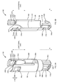
- FIGS. 1A and 1B illustrate an exemplary syringe 100 including a substantially tubular syringe body 102 for holding a therapeutic agent.
- FIG. 1A illustrates a side view of the exemplary syringe 100 .
- FIG. 1B illustrates a cross-sectional view of the exemplary syringe 100 bisected along the longitudinal axis L.
- An injection needle may be coupled at a distal end of the syringe body 102 .
- the injection needle may be covered and protected by a soft needle shield 104 and a rigid needle shield 106 that surrounds the soft needle shield 104 .
- One or more apertures 108 may be provided in a side wall of the rigid needle shield 106 to allow a portion of the soft needle shield 104 to extend through the apertures 108 . This permits the soft needle shield 104 and the rigid needle shield 106 to latch together which, in turn, permits removal of both the soft needle shield 104 and the rigid needle shield 106 when the rigid needle shield 106 is pulled away from the syringe body 102 in the distal direction (represented by arrow R), thereby exposing the injection needle for use in performing an injection.
- a ridged portion 110 may be provided in the exterior surface of the rigid needle shield 106 .
- the ridged portion 110 may include one or more alternating outwardly-projecting ridges interspaced with grooves, and may thereby provide a region of higher friction contact for removal of the rigid needle shield 106 from the syringe.
- Exemplary embodiments provide a needle shield remover that reliably engages with a distal cap of an automatic injection device and with one or more needle shields coupled to a syringe of the device.
- An exemplary needle shield remover includes one or more inwardly-projecting shield engagement mechanisms that reliably engage with the needle shields, and one or more cap engagement mechanisms that reliably engage with the distal cap.
- the needle shield remover reliably removes the needle shields (e.g., a soft needle shield and a rigid needle shield) from the syringe, thereby exposing the injection needle for performing an injection.
- an exemplary needle shield remover is engaged to a needle shield coupled to a syringe, prior to insertion of the syringe and needle shield remover assembly into a housing of the automatic injection device.
- This exemplary assembly method allows visual inspection, outside the housing of the device, to ensure that the needle shield remover is correctly and reliably engaged to the needle shield before the syringe and needle shield remover assembly is inserted into the housing.
- an apparatus for removing a needle shield from a syringe.
- the apparatus includes a tubular member for enclosing the needle shield coupled to the syringe.
- the apparatus also includes one or more cap engagement mechanisms provided at a distal end of the tubular member and configured for engagement with a distal cap provided for covering a distal end of the syringe.
- the apparatus also includes one or more shield engagement mechanisms provided at a proximal end of the tubular member and configured for engagement with the needle shield. When the apparatus is pulled away from the syringe, the one or more shield engagement mechanisms exert force against the needle shield to remove the needle shield from the syringe.
- an automatic injection device in accordance with another exemplary embodiment, includes a syringe, a needle shield coupled to a distal end of the syringe, and a distal cap for covering the needle shield.
- the automatic injection device also includes a needle shield remover disposed between the needle shield and the distal cap.
- the needle shield includes a tubular member for enclosing the needle shield coupled to the syringe, one or more cap engagement mechanisms provided at a distal end of the tubular member and engaged with the distal cap, and one or more shield engagement mechanisms provided at a proximal end of the tubular member and engaged with the needle shield.
- a method for assembling an automatic injection device.
- the method includes coupling a needle shield to a distal end of a syringe.
- the method also includes engaging one or more shield engagement mechanisms of a needle shield remover to the needle shield.
- the method further includes inserting an assembly comprising the syringe, the needle shield and the needle shield remover into a housing of the automatic injection device.
- FIG. 1A illustrates a side view of an exemplary syringe.
- FIG. 1B illustrates a cross-sectional view of the exemplary syringe of FIG. 1A bisected along the longitudinal axis L.
- FIG. 2A illustrates a side view of an exemplary needle shield remover engaged to a syringe.
- FIG. 2B illustrates another side view of the exemplary needle shield remover of FIG. 2A rotated by about 90 degrees.
- FIG. 2C illustrates a cross-sectional perspective view of the exemplary needle shield remover of FIGS. 2A and 2B engaged to a syringe and a distal cap.
- FIG. 2D is a bottom view of the exemplary distal cap of FIG. 2C showing engagement of the needle shield remover to the distal cap.
- FIG. 3A illustrates a perspective view of an exemplary syringe sleeve.
- FIG. 3B illustrates a cross-sectional perspective view of the exemplary syringe sleeve of FIG. 3A bisected along a longitudinal axis L.
- FIG. 4A illustrates a perspective view of an assembly of an exemplary syringe sleeve housing an exemplary syringe that is fitted with an exemplary needle shield remover.
- FIG. 4B illustrates a transverse cross-sectional view of the exemplary assembly of FIG. 4A .
- FIG. 5A illustrates a perspective view of an exemplary needle shield remover.
- FIG. 5B illustrates a cross-sectional perspective view of the exemplary needle shield remover of FIG. 5A bisected along a longitudinal axis L.
- FIGS. 6 illustrates a cross-sectional perspective view of the exemplary needle shield remover of FIGS. 5A and 5B assembled with a syringe and a distal cap.
- FIG. 7 illustrates a cross-sectional perspective view of the exemplary needle shield remover of FIGS. 5A and 5B assembled with a syringe, a distal cap and a syringe sleeve.
- FIG. 8 illustrates a front cross-sectional view of the exemplary assembly of FIG. 7 .
- FIG. 9 illustrates a bottom view of an exemplary distal cap that is applicable to FIGS. 6-8 .
- FIG. 10A illustrates a perspective view of an exemplary needle shield remover.
- FIG. 10B illustrates a cross-sectional perspective view of the exemplary needle shield remover of FIG. 10A bisected along a longitudinal axis L.
- FIGS. 11 illustrates a cross-sectional perspective view of the exemplary needle shield remover of FIGS. 10A and 10B assembled with a syringe and a distal cap.
- FIG. 12 illustrates a cross-sectional perspective view of the exemplary needle shield remover of FIGS. 10A and 10B assembled with a syringe, a distal cap and a syringe sleeve.
- FIG. 13 illustrates a front cross-sectional view of the exemplary assembly of FIG. 12 .
- FIG. 14 illustrates a bottom view of an exemplary distal cap that is applicable to FIGS. 11-13 .
- FIG. 15A illustrates a perspective view of an exemplary needle shield remover.
- FIG. 15B illustrates a cross-sectional perspective view of the exemplary needle shield remover of FIG. 15A bisected along a longitudinal axis L.
- FIGS. 16 illustrates a cross-sectional perspective view of the exemplary needle shield remover of FIGS. 15A and 15B assembled with a syringe and a distal cap.
- FIG. 17 illustrates a cross-sectional perspective view of the exemplary needle shield remover of FIGS. 15A and 15B assembled with a syringe, a distal cap and a syringe sleeve.
- FIG. 18 illustrates a front cross-sectional view of the exemplary assembly of FIG. 17 .
- FIG. 19 illustrates a bottom view of an exemplary distal cap that is applicable to FIGS. 16-18 .
- FIG. 20 illustrates a cross-sectional view of another exemplary needle shield remover bisected along the longitudinal axis L.
- FIG. 21 illustrates a cross-sectional view of another exemplary needle shield remover bisected along the longitudinal axis L .
- FIG. 22 illustrates a cross-sectional view of another exemplary needle shield remover bisected along the longitudinal axis L.
- FIG. 23 illustrates a cross-sectional view of another exemplary needle shield remover bisected along the longitudinal axis L.
- FIG. 24 illustrates a cross-sectional view of another exemplary needle shield remover bisected along the longitudinal axis L.
- FIG. 25 is a flowchart of an exemplary method for assembling an exemplary needle shield remover with a syringe and a distal cap of an automatic injection device, in which the needle shield remover is assembled with a syringe prior to insertion of the syringe into the housing of the device.
- FIG. 26 illustrates a device view of the exemplary method of FIG. 25 by which an exemplary automatic injection device may be assembled.
- FIG. 27 is a flowchart of an exemplary method for assembling an exemplary needle shield remover with a syringe and a distal cap of an automatic injection device, in which the needle shield remover is assembled with a syringe after insertion of the syringe into the housing of the device.
- FIG. 28 is a flowchart of an exemplary method for using an exemplary automatic injection device to administer an injection.
- a removable distal cap includes a mechanism that snaps into position in a gap formed between the syringe body and the needle shield.
- the mechanism in the cap allows the needle shield to be removed as well because of its engagement with the cap.
- a needle shield removal mechanism that consistently fits within the gap formed between the syringe body and the needle shield.
- Exemplary embodiments address the deficiencies in conventional automatic injection devices by providing a needle shield remover that reliably engages and removes one or more needle shields when a removable distal cap is removed from a distal end of the device.
- An exemplary needle shield remover may be provided separately from one or more needle shields and from a removable distal cap covering the distal end of the device.
- the needle shield remover may include one or more inwardly-projecting shield engagement mechanisms that reliably engage with one or more needle shields, and one or more cap engagement mechanisms that reliably engage with the removable distal cap.
- the exemplary needle shield remover reliably removes the needle shields from the syringe, thereby exposing the injection needle for performing an injection.
- U.S. Provisional Patent Application No. 61/435,467 filed Jan. 24, 2011, to which the present application claims priority, teaches some exemplary needle shield removers that employ the concept of “float” relative to a removable distal cap and a needle shield remover attached thereto prior to placement of the removable distal cap onto an automatic injection device.
- U.S. Provisional Patent Application No. 61/435,467, filed Jan. 24, 2011, also teaches some exemplary needle shield removers that are “floatless” and do not employ the concept of “float” relative to a removable distal cap and a needle shield remover attached to an automatic injection device.
- float refers to the structure, function and operation of a needle shield remover and a removable distal cap that form a single assembly and, as part of the assembly, slide relative to each other along a longitudinal axis during attachment to an automatic injection device, where the relative movement exceeds acceptable tolerances that account for manufacturing variations in the assembled components.
- the employment of “float” refers to a single assembly formed of a needle shield remover and a removable distal cap that are pre-assembled before the needle shield remover is engaged to a needle shield. That is, in an automatic injection device that employs “float,” the pre-assembled removable distal cap and needle shield remover form a one-piece assembly that is engaged to the needle shield and the automatic injection device after the syringe is loaded into the automatic injection device.
- the pre-assembled removable distal cap and needle shield remover are engaged to the automatic injection device in at least two steps in which the distal cap is first engaged to the automatic injection device, and subsequently the needle shield remover is engaged to the needle shield by sliding along a longitudinal axis from a first position to an second engaged position while the distal cap remains engaged to the automatic injection device.
- exemplary needle shield removers and distal caps taught in the present application are “floatless” and do not rely on the concept of “float” for correctly and reliably assembling a needle shield remover and a removable distal cap in an automatic injection device.
- the concept of “floatless” or “floatlessness” refers to the structure, function and operation of an exemplary needle shield remover and a removable distal cap that are not pre-assembled as a single assembly and that are not configured to slide relative to each other along a longitudinal axis during attachment to an automatic injection device in order to engage the needle shield remover to the needle shield, where the relative movement exceeds acceptable tolerances that account for manufacturing variations in the assembled components.
- an exemplary needle shield remover is an assembly engaged to a needle shield attached to a syringe prior to insertion of the syringe and needle shield remover assembly into a housing of the automatic injection device.
- the removable distal cap is then engaged to the device in a one-step process in which coupling the distal cap to the distal end of the device housing also engages the distal cap with the needle shield remover.
- the structure, function and operation of the removable distal cap and the needle shield remover in “floatless” embodiments do not accommodate pre-assembly as a one piece assembly and do not accommodate movement of the needle shield remover attached to the removable distal cap from a first position to an engaged position along a longitudinal axis.
- Automatic injection devices that do not rely on the concept of “float” to assemble an exemplary needle shield remover and a distal cap are advantageous over automatic injection devices that rely on the “float” concept. This is because reliance on the relative movement between the needle shield remover and the distal cap in automatic injection devices that use “float” increases the risk of unreliable and incorrect engagement of the needle shield remover with the needle shield, and thereby reduces robustness of the assembly.
- the ability, in exemplary embodiments, to assemble the exemplary needle shield remover with the needle shield outside the device housing and outside the distal cap allows visual inspection of the assembly process to ensure that the needle shield remover is correctly and reliably engaged with a gap between the syringe body and the needle shield.
- automated injection device and “autoinjector,” as used herein, refer to a device that enables a patient to self-administer a therapeutically effective dose of a therapeutic agent, wherein the device differs from a conventional syringe by the inclusion of a mechanism for automatically delivering the therapeutic agent to the patient by injection when the mechanism is engaged.
- vessel and “container,” as used herein, refer to a syringe or cartridge that may be used in an exemplary automatic injection device for holding a dose of a therapeutic agent.
- syringe and “cartridge,” as used herein, refer to a sterile barrel portion of an automatic injection device that is filled with a dose of a therapeutic agent prior to distribution or sale of the device to a patient or other non-medical professional for administration of the therapeutic agent to a patient.
- a distal end of the barrel portion of a syringe may be coupled to a sterile hypodermic injection needle.
- a distal end of the barrel portion of a cartridge may not be coupled to an injection needle. That is, in exemplary embodiments, a syringe may be a cartridge with a pre-attached injection needle coupled to its barrel portion.
- Exemplary embodiments described herein with reference to a syringe assembly may also be implemented using a cartridge assembly.
- exemplary embodiments described herein with reference to a cartridge assembly may also be implemented using a syringe assembly.
- pre-filled syringe refers to a syringe that is filled with a therapeutic agent immediately prior to administration of the therapeutic agent to a patient, and a syringe that is filled with a therapeutic agent and stored in this pre-filled form for a period of time before administration of the therapeutic agent to a patient.
- injection needle and “needle,” as used herein, refer to a needle in an automatic injection device that is inserted into a patient's body to deliver a dose of a therapeutic agent into the patient's body.
- the injection needle may be directly coupled to or may otherwise be in contact with a syringe assembly or a cartridge assembly that holds a dose of the therapeutic agent.
- the injection needle may be indirectly coupled to the syringe or cartridge assembly, for example, via a syringe needle and/or a transfer mechanism that provides fluid communication between the syringe or cartridge assembly and the injection needle.
- thermoplastic material refers to a material that has the property of softening or fusing when heated and of hardening and becoming rigid again when cooled. Thermoplastic materials can be re-melted and cooled repeatedly without undergoing any appreciable chemical change.
- a thermoplastic is a polymer that turns to a liquid when heated and freezes to a very glassy state when cooled sufficiently. Most thermoplastics are high-molecular-weight polymers whose chains associate through weak Van der Waals forces (polyethylene); stronger dipole-dipole interactions and hydrogen bonding (nylon); or even stacking of aromatic rings (polystyrene).
- thermoplastic polymers differ from thermosetting polymers (vulcanized rubber) as they can, unlike thermosetting polymers, be re-melted and re-molded.
- thermoplastic materials are addition polymers; e.g., vinyl chain-growth polymers such as polyethylene and polypropylene.
- pre-injection state refers to a state of an automatic injection device prior to activation of the device, i.e., prior to the start of delivery of a therapeutic agent contained in the device.
- injection state refers to one or more states of an automatic injection device during the delivery of a therapeutic agent contained in the device.
- post-injection state refers to completion of delivery of a therapeutically effective dose of a therapeutic agent contained in the device, or removal of the device from the patient prior to completion of delivery of a therapeutically effective dose of the therapeutic agent.
- patient or “user,” as used herein, refers to any type of animal, human or non-human, that may be administered a substance using exemplary automatic injection devices.
- proximal refers to a portion, end or component of an exemplary automatic injection device that is farthest from an injection site on a patient's body when the device is held against the patient for an injection or for mimicking an injection.
- distal refers to a portion, end or component of an exemplary automatic injection device that is closest to an injection site on a patient's body when the device is held against the patient for an injection or for mimicking an injection.
- planar is used herein, in a broad lay sense, to mean exactly planar or approximately planar within some tolerance from the exactly planar.
- concave is used herein, in a broad lay sense, to mean exactly concave or approximately concave within some tolerance from the exactly concave.
- convex is used herein, in a broad lay sense, to mean exactly convex or approximately convex within some tolerance from the exactly convex.
- elliptical is used herein, in a broad lay sense, to mean exactly elliptical or approximately elliptical within some tolerance from the exactly elliptical.
- oval is used herein, in a broad lay sense, to mean exactly oval or approximately oval within some tolerance from the exactly oval.
- rectangular is used herein, in a broad lay sense, to mean exactly rectangular or approximately rectangular within some tolerance from the exactly rectangular.
- parallel is used herein, in a broad lay sense, to mean exactly parallel or approximately parallel within some tolerance from the exactly parallel.
- straight is used herein, in a broad lay sense, to mean exactly straight or approximately straight within some tolerance from the exactly straight.
- adjacent is used herein, in a broad lay sense, to mean immediately adjacent or approximately adjacent within some tolerance.
- transverse axis is used herein to refer to an axis substantially perpendicular to a longitudinal axis.
- inwardly-projecting is used herein to refer to one or more tabs or teeth on a needle shield remover extending length wise along a longitudinal axis and having a proximal end attached to a tubular structure of the needle shield remover and a distal end detached from the tubular structure of the needle shield remover and projecting inwardly into an inner cavity of the tubular structure.
- a needle shield remover may be provided as a separate component from a needle shield for covering an injection needle and from a removable distal cap for covering a distal end of an automatic injection device.
- the needle shield remover may include one or more cap engagement mechanisms configured for engagement with the removable distal cap so that removal of the distal cap from the device housing automatically removes the needle shield remover as well.
- the needle shield remover may include one or more inwardly-projecting shield engagement mechanisms configured for directly or indirect engagement with a rigid needle shield (in a device that includes a rigid needle shield) and/or a soft needle shield (in a device that includes a soft needle shield but lacks a rigid needle shield). Since the needle shield remover is engaged to the needle shield, when the needle shield remover is removed from the device housing (e.g., by removal of the distal cap engaged to the needle shield remover), this results in the removal of the needle shield engaged to the needle shield remover.
- Exemplary needle shield removers are configured and designed for quick, easy and reliable engagement to both the distal cap and to a needle shield.
- One or more exemplary methods may be used to assemble an exemplary needle shield remover to a needle shield coupled to a syringe.
- an exemplary needle shield remover may be assembled with a needle shield coupled to a syringe after the syringe has been inserted into the housing of the device.
- an exemplary needle shield remover that is provided as a separate component from a distal cap and a syringe—may be assembled with a needle shield coupled to a syringe prior to insertion of the syringe into the housing of the device.
- the ability to assemble the needle shield remover to the needle shield outside the device housing allows visual inspection of the assembly process to ensure that the needle shield remover reliably engages the needle shield on the syringe before the syringe assembly is inserted into the device housing.
- assembly of the exemplary needle shield remover in the automatic injection device allows one to be certain that, when the syringe assembly is inserted into the device housing, the needle shield remover is engaged reliably and correctly with the needle shield, thereby resolving the issue of unreliable positioning of needle shield removal mechanisms in conventional automatic injection devices.
- FIGS. 2A-2D illustrate an exemplary needle shield remover 200 engaged to a syringe 202 and to a distal cap 204 .
- FIG. 2A illustrates a side view of an exemplary needle shield remover engaged to a syringe.
- FIG. 2B illustrates another side view of the exemplary needle shield remover of FIG. 2A rotated by about 90 degrees.
- FIG. 2C illustrates a cross-sectional perspective view of the exemplary needle shield remover of FIGS. 2A and 2B engaged to a syringe and a distal cap.
- FIG. 2D is a bottom view of the exemplary distal cap of FIG. 2C showing engagement of the needle shield remover to the distal cap.
- the length of an exemplary needle shield remover 200 may range from about 10 mm to about 50 mm, but is not limited to this exemplary range.
- FIGS. 2A-2D are presented for the purpose of generally describing the structure, function and operation of an exemplary needle shield remover. Certain specific but non-limiting exemplary embodiments of needle shield removers are described in connection with FIGS. 5-24 .
- an injection needle (not pictured) is coupled to the distal end of the syringe 202 .
- the needle is covered with a soft needle shield 206 that is, in turn, positioned within and covered by a rigid needle shield 208 . Portions of the soft needle shield 206 may extend through one or more apertures in the rigid needle shield 208 as shown in FIG. 2B .
- the exemplary needle shield remover 200 is positioned over the rigid needle shield 208 .
- the needle shield remover 200 may be used to remove all of the needle shields when the needle shield remover 200 is removed from its engagement to the syringe 202 .
- the exemplary needle shield remover 200 may include a single tubular member. In other exemplary embodiments, the needle shield remover 200 may include two, three or more tubular members. In the exemplary embodiment illustrated in FIGS. 2A-2D , the exemplary needle shield remover 200 may include a proximal tubular member 210 that, at its distal edge, is integrally coupled to a distal tubular member 212 in some exemplary embodiments.
- the distal tubular member 212 may have a smaller outer diameter and a shorter length than the proximal tubular member 210 , and may extend along a shorter length of the needle shield remover 200 along the longitudinal axis L than the proximal tubular member 210 .
- a transition portion 214 may extend between the proximal tubular member 210 and the distal tubular member 212 .
- An exemplary transition portion 214 may be a stepped transition, a ramped transition, or a combination of both.
- the distal tubular member 212 may be substantially cylindrical in shape with a substantially circular or oval cross-section.
- the side wall of the distal tubular member 212 may include one or more platform structures that project longitudinally from the face of the distal tubular member 212 toward a removable distal cap.
- a platform structure may include a first longitudinally-projecting portion 216 a , a second longitudinally-projecting portion 216 b , and a transverse portion 216 c that extends between the longitudinally-projecting portions 216 a , 216 b at a distal end of the platform structure.
- the transverse portion 216 c may support one or more cap engagement mechanisms in one exemplary embodiment.
- an exemplary platform structure may support or define or provide one or more cap engagement mechanisms 218 a , 218 b that project radially outwardly from the platform structure.
- Exemplary cap engagement mechanisms may take the form of protrusions, teeth, clips, and other suitable engagement mechanisms.
- Exemplary cap engagement mechanisms 218 a , 218 b may have any suitable dimensions and structure.
- Exemplary lengths of the cap engagement mechanisms may include, but are not limited to, about 1, 2, 2.1, 2.2, 2.3, 2.4, 2.5, 2.6, 2.7, 2.8, 2.9, 3, 3.1, 3.2, 3.3, 3.4, 3.5, 3.6, 3.7, 3.8, 3.9, 4, 4.1, 4.2, 4.3, 4.4, 4.5, 4.6, 4.7, 4.8, 4.9, 5, 5.1, 5.2, 5.3, 5.4, 5.5, 5.6, 5.7, 5.8, 5.9, 6, 6.5, 7 mm, all intermediate numbers, and the like.
- a first cap engagement mechanism 218 a and a second cap engagement mechanism 218 b are provided at opposite sides of the platform structure, i.e., separated from each other by about 180 degrees.
- the cap engagement mechanisms are provided separately and spaced from each other.
- a single cap engagement mechanism may be provided to extend in an annular manner around the platform structure.
- exemplary needle shield removers may include any suitable number of cap engagement mechanisms extending from the platform structure including, but not limited to, one, two, three, four, five, six, seven, and the like.
- each cap engagement mechanism 218 a , 218 b may be coupled to or may be provided integrally with the platform structure, and a second end of each cap engagement mechanism 218 a , 218 b may be suspended over a corresponding gap 220 a , 220 b between the second end of the cap engagement mechanism and the distal tubular member 212 .
- the cap engagement mechanisms 218 a , 218 b may be coupled to the cap 204 so that removal of the cap also automatically removes the needle shield remover 200 .
- FIG. 2C illustrates a cross-sectional perspective view of the removable distal cap 204 in which a central aperture 226 is provided along longitudinal axis L.
- FIG. 2D is a bottom view of a distal face 222 of the distal cap 204 showing engagement of the needle shield remover 200 to the distal cap 204 .
- One or more inwardly-projecting stop portions 228 a , 228 b may be provided at the interior surface of the central aperture 226 of the distal cap 204 .
- the inwardly-projecting stop portions 228 a , 228 b may not extend along the entire periphery of the central aperture 226 .
- the inwardly-projecting stop portions may extend along the entire periphery of the central aperture 226 .
- the one or more cap engagement mechanisms 218 a , 218 b of the needle shield remover 200 may be made to fit through the aperture 226 of the distal cap 204 .
- inwardly-projecting stop portions 228 a , 228 b e.g., flanges or raised edges
- inwardly-projecting stop portions 228 a , 228 b e.g., flanges or raised edges
- the needle shield remover 200 allows the needle shield remover 200 to be reliably engaged to the distal cap 204 upon assembly and during removal of the cap 204 from the device housing, thus causing removal of the distal cap 204 from the device housing to automatically remove the needle shield remover 200 as well. Since the needle shield remover 200 is reliably engaged to one or more needle shields 206 , 208 , removal of the needle shield remover, in turn, automatically removes the needle shields as well.
- the cap engagement mechanisms 218 a , 218 b may snap into place in the aperture 226 of the distal cap 204 so that the inwardly-projecting stop portions 228 a , 228 b are positioned within the gap 220 a , 220 b of the needle shield remover 200 .
- this decrease in the force may be sensed by a user or automatically by an assembly machine to determine that the inwardly-projecting stop portions 228 a , 228 b of the distal cap 204 have been reliably positioned within the gap 220 a , 220 b of the needle shield remover 200 .
- an audible “click” sound may be emitted to provide an audible indication that the distal cap 204 has been successfully engaged with the needle shield remover 200 .
- the proximal tubular member 210 of the needle shield remover 200 may be substantially cylindrical in shape with a substantially circular or oval cross-section.
- the side wall of the first tubular member 210 may enclose and define a substantially cylindrical cavity for housing the injection needle covered by the soft needle shield 206 and the rigid needle shield 208 .
- the side wall of the proximal tubular member 210 may define and/or include one or more inwardly-projecting shield engagement mechanisms 230 a , 230 b that are biased by the side wall to reliably remain positioned within a gap 232 formed between the body of the syringe 202 and the proximal edge of the rigid needle shield 208 .
- a first inwardly-projecting shield engagement mechanism 230 a and a second inwardly-projecting shield engagement mechanism 230 b are provided at opposite sides of the needle shield remover 200 , i.e., separated from each other by about 180 degrees.
- the inwardly-projecting shield engagement mechanisms 230 a , 230 b may be positioned in the gap 232 during the assembly process and may reliably be positioned in the gap during the use of the device.
- the inwardly-projecting shield engagement mechanisms 230 a , 230 b exert force in the direction R against the peripheral edge of the rigid needle shield 208 , thereby pulling the rigid needle shield 208 and the soft needle shield 206 away from the syringe body 202 in the direction R and exposing the injection needle for performing an injection.
- Exemplary inwardly-projecting shield engagement mechanisms 230 a , 230 b may be configured to bias against the gap 232 with a sufficient force to ensure that when the needle shield remover is removed from the device, the needle shield remover 200 remains engaged with the rigid needle shield 208 and thereby reliably removes the rigid needle shield 208 from the body of the syringe 202 .
- Exemplary inwardly-projecting shield engagement mechanisms 230 a , 230 b may be configured to interface with the gap 232 over a sufficient area or width to apply a sufficient force to remove the rigid needle shield when the needle shield remover is pulled away from the syringe.
- a width of an exemplary inwardly-projecting shield engagement mechanism 230 a , 230 b that interfaces with the gap 232 may range from about 3 mm to about 7 mm, but is not limited to this exemplary range.
- the edge of the inwardly-projecting shield engagement mechanisms 230 a , 230 b that interfaces with the gap 232 may be substantially straight.
- the edge of the inwardly-projecting shield engagement mechanisms 230 a , 230 b that interfaces with the gap 232 may be serrated.
- the inner diameter of the needle shield remover 200 at the inwardly-projecting shield engagement mechanisms 230 a , 230 b may be less than the outer diameter of the rigid needle shield 208 .
- the inner diameter of the needle shield remover 200 at the inwardly-projecting shield engagement mechanisms 230 a , 230 b may also be less than the outer diameter of the syringe body 202 .
- the inner diameter of the needle shield remover 200 at the inwardly-projecting shield engagement mechanisms 230 a , 230 b may be substantially equal to the outer diameter of the gap 232 formed between the syringe body and the proximal end of the rigid needle shield 208 .
- This configuration of the inwardly-projecting shield engagement mechanisms 230 a , 230 b allows the shield engagement mechanisms to snap into place at the gap 232 in a reliable and tight manner so that disengagement requires a minimal threshold level of force. This configuration also prevents creep of the inwardly-projecting shield engagement mechanisms 230 a , 230 b out of the gap 232 before the needle shield remover 200 is pulled away from the syringe body.
- An exemplary inner diameter of the needle shield remover 200 may range from about 5 mm to about 20 mm, but is not limited to this exemplary range.
- An exemplary inner diameter of the needle shield remover 200 may range from about 8 mm to about 11 mm in some exemplary embodiments.
- An exemplary inner diameter of the needle shield remover 200 may be about 8.5 mm in an exemplary embodiment.
- An exemplary inner diameter of the needle shield remover 200 may be about 11 mm in another exemplary embodiment.
- the inwardly-projecting shield engagement mechanisms 230 a , 230 b may snap into place at the gap 232 as the needle shield remover 200 is inserted over the rigid needle shield 208 .
- the inwardly-projecting shield engagement mechanisms 230 a , 230 b snap into place at the gap 232 , there may be a decrease in the force experienced against insertion of the needle shield remover 200 over the rigid needle shield 208 .
- this decrease in the force may be sensed by a user or automatically by an assembly machine to determine that the inwardly-projecting shield engagement mechanisms 230 a , 230 b have been successfully engaged to the gap 232 .
- the positioning of the inwardly-projecting shield engagement mechanisms 230 a , 230 b in the gap 232 may emit an audible “click” sound that provides an audible indication that the needle shield remover 200 has been successfully engaged with the rigid needle shield 208 .
- exemplary needle shield removers may include any suitable number of inwardly-projecting shield engagement mechanisms 230 a , 230 b including, but not limited to, one, two, three, four, five, six, seven, and the like.
- Exemplary inwardly-projecting shield engagement mechanisms may take the form of protrusions, teeth, clips, and other suitable engagement mechanisms.
- the one or more inwardly-projecting shield engagement mechanisms 230 a , 230 b are configured and positioned to consistently and reliably fit within the gap 232 formed between the body of the syringe 202 and the proximal edge of the rigid needle shield 208 .
- one or more inwardly-projecting shield engagement mechanisms 230 a , 230 b may be configured and positioned to consistently and reliably engage with an aperture in the rigid needle shield 208 (for example, exemplary aperture 108 illustrated in FIG. 1A ).
- one or more inwardly-projecting shield engagement mechanisms 230 a , 230 b may be configured and positioned to consistently and reliably engage with a ridged portion in the rigid needle shield 208 (for example, exemplary ridged portion 110 illustrated in FIG. 1A ). This allows automatic removal of the rigid needle shield 208 (and an associated soft needle shield 206 ) by the inwardly-projecting shield engagement mechanisms 230 a , 230 b of the needle shield remover 200 , when the needle shield remover 200 is removed from the device housing by engagement of the needle shield remover 200 with a distal cap 204 that is removed by a user.
- one or more inwardly-projecting shield engagement mechanisms 230 a , 230 b of the needle shield remover 200 may be configured and positioned to consistently and reliably engage with the soft needle shield 206 .
- the inwardly-projecting shield engagement mechanisms 230 a , 230 b may be configured and positioned to engage any other suitable component on the rigid needle shield 208 and/or the soft needle shield 206 .
- the inwardly-projecting shield engagement mechanisms 230 a , 230 b are provided in a component separate from the rigid needle shield 208 (i.e., in the needle shield remover 200 ), and the shield engagement mechanisms 230 a , 230 b are not permanently engaged with the rigid needle shield 208 .
- the inwardly-projecting shield engagement mechanisms 230 a , 230 b of the needle shield remover 200 may be permanently engaged with the rigid needle shield 208 , for example, using glue or epoxy.
- the side wall of the proximal tubular member 210 of the needle shield remover 200 may also define one or more cutout portions 234 for allowing a user to view the contents of the syringe 202 and/or to view an end-of-injection indicator from outside the device housing. That is, the cutout portions 234 of the proximal tubular member 210 may align with a transparent inspection window or inspection aperture provided in the device housing to allow a user to view the contents of the syringe 202 and/or to view an end-of-injection indicator from outside the device.
- each cutout portion 234 may have a substantially concave shape or a semicircular shape, but is not limited to these exemplary shapes.
- An exemplary width of the cutout portions may range from about 3 mm to about 7 mm, but is not limited to this exemplary range.
- Exemplary widths of the cutout portions may include, but are not limited to, about 4.0, 4.1, 4.2, 4.3, 4.4, 4.5, 4.6, 4.7, 4.8, 4.9, 5.0, 5.1, 5.2, 5.3, 5.4, 5.5, 5.6, 5.7, 5.8, 5.9, 6.0 mm, and the like.
- One or more additional protrusions and/or grooves may be provided in the exterior surface of the proximal tubular member 210 and/or the distal tubular member 212 in order to facilitate engagement of the needle shield remover 200 with another component of the automatic injection device, e.g., a syringe sleeve that cooperatively engages with and covers a proximal portion of the needle shield remover 200 , a removable cap 204 that covers a distal portion of the needle shield remover 200 , and the like.
- a syringe sleeve that cooperatively engages with and covers a proximal portion of the needle shield remover 200
- a removable cap 204 that covers a distal portion of the needle shield remover 200
- one or more longitudinally-extending grooves 236 a , 236 b may be provided in the exterior surface of the needle shield remover 200 to movably engage with a syringe sleeve.
- the syringe sleeve may allow relative movement of the syringe sleeve and/or the needle shield remover 200 along the longitudinal axis L, but may hold the needle shield remover 200 in a substantially fixed axial orientation relative to the syringe sleeve. This ensures that the cutout portions 234 of the needle shield remover 200 are maintained in alignment with a transparent inspection window or inspection aperture provided in the syringe sleeve and with a transparent inspection window or inspection aperture provided in the device housing, thus allowing a user to view the contents of the syringe 202 and/or to view an end-of-injection indicator through the inspection windows or apertures. Certain exemplary embodiments of syringe sleeves are described in connection with FIGS. 3 and 4 .
- the needle shield remover 200 may be provided as a separate component from the distal cap 204 of the automatic injection device.
- a needle shield remover 200 may be provided integrally with the distal cap 204 , for example, by integrally coupling the cap engagement mechanisms 218 a , 218 b of the needle shield remover 200 with the distal cap 204 of the device.
- An exemplary automatic injection device may include a syringe sleeve that is a structural member for enveloping a portion of a syringe fitted with a needle shield remover.
- the syringe sleeve may be configured to hold and guide the syringe fitted with a needle shield remover, so that the syringe may move forwardly within and relative to the housing of the device from a retracted position (i.e., farther away from the injection site) to an injection position (i.e., closer to the injection site in which the injection needle projects from an open end of the device housing).
- the syringe may rest within the syringe sleeve, and both may be housed within the housing of the automatic injection device.
- exemplary automatic injection devices may not provide a syringe sleeve.
- An exemplary syringe sleeve may include a transparent inspection window or inspection aperture that may be aligned with both a cutout portion of the needle shield remover and an inspection window or inspection aperture provided the device housing, so that the contents of the syringe may be reliably viewed from outside the device housing.
- the syringe sleeve may maintain the needle shield remover in a substantially fixed axial orientation so that the cutout portion of the needle shield remover is aligned with the inspection window or inspection aperture of the syringe sleeve and the device housing. This ensures that movement of the needle shield remover within the device does not lead to obscuration of the inspection window or inspection aperture of the device housing.
- the syringe sleeve may have any suitable configuration, shape and size suitable for accommodating the syringe fitted with the needle shield remover, and for axially orienting the cutout portion of the needle shield remover in alignment with the inspection window or inspection aperture of the device housing.
- the syringe sleeve may be formed of any suitable material including, but not limited to, thermoplastic polymers, e.g., polycarbonates.
- FIG. 3A illustrates a perspective view of an exemplary syringe sleeve 300 .
- FIG. 3B illustrates a cross-sectional perspective view of the exemplary syringe sleeve 300 bisected along a longitudinal axis L.
- the exemplary syringe sleeve 300 may include a tubular member 302 that may be substantially cylindrical in shape with a substantially circular or oval cross-section.
- the side wall of the tubular member 302 may enclose and define a substantially cylindrical cavity for housing a syringe fitted with a needle shield remover.
- the side wall of the tubular member 302 may define and/or include one or more transparent inspection windows or inspection apertures 304 for allowing a user of the device to view the contents of the syringe and/or an indicator.
- the inspection window or inspection aperture of the tubular member 302 may be aligned with the cutout portion of the needle shield remover and with the inspection window or inspection aperture of the automatic injection device housing to provide a clear unobstructed view of the syringe contents and/or an indicator.
- the inspection window or inspection aperture 304 may have any suitable configuration, size and shape for allowing viewing of the contents of the syringe.
- Exemplary shapes of the inspection window or inspection aperture 304 may include, but are not limited to, a substantially elongated oval or elliptical shape, a substantially elongated rectangular shape, and the like.
- the inspection window or inspection aperture 304 may have a longer length along the longitudinal axis L than a width along a transverse axis.
- the entire syringe sleeve 300 may be formed of a transparent material.
- the inspection window or inspection aperture 304 may be the only component of the syringe sleeve 300 that is formed of a transparent material or is an aperture in the tubular member 302 .
- An exterior surface of the tubular member 302 may include one or more raised structures and/or grooves to engage with one or more other components of the automatic injection device.
- An exemplary raised structure may be one or more longitudinally-extending rails 306 , 308 that may fit movably along internal longitudinally-extending grooves and/or protrusions (not pictured) provided on an interior surface of the device housing.
- the rails 306 , 308 may allow the syringe sleeve 300 to move longitudinally relative to the device housing, and may allow the syringe sleeve 300 to be held in a fixed axial orientation relative to the device housing.
- the rails 306 , 308 may extend along the entire length of the tubular member 302 .
- one, two, three, four, five, six rails may be provided in the exterior surface of the tubular member 302 , but the number of rails is not limited to these exemplary numbers.
- Exemplary lengths of the rails 306 , 308 or grooves and/or protrusions in the exterior surface of the tubular member 302 may range from about 1 mm to about 6 mm, but are not limited to this exemplary range.
- An interior surface of the tubular member 302 may include one or more raised structures and/or grooves to engage with one or more other components of the automatic injection device.
- An exemplary raised structure may be one or more longitudinally-extending rails 310 that may fit movably along internal longitudinally-extending grooves and/or protrusions provided on an exterior surface of a needle shield remover.
- the rails 310 may allow the syringe sleeve 300 to move longitudinally relative to the needle shield remover and to allow the needle shield remover to move longitudinally relative to the syringe sleeve 300 .
- the rails 310 may also allow the needle shield remover to be held in a fixed axial orientation relative to the syringe sleeve 300 .
- Exemplary lengths of the rails 310 or grooves on the interior surface of the tubular member 302 may range from about 1 mm to about 6 mm, but are not limited to this exemplary range.
- a proximal portion of the tubular member 302 may be coupled to one or more longitudinally-extending syringe alignment guides 311 , 312 , 314 , 316 for aligning a syringe in a substantially fixed axial orientation relative to the syringe sleeve 300 .
- This ensures that the inspection window or inspection aperture 304 of the tubular member 302 is reliably aligned with a corresponding cutout portion of an exemplary needle shield remover attached to the syringe.
- syringe alignment guides may be used in exemplary syringe sleeves.
- two pairs of syringe alignment guides may be provided so that the pairs are provided on opposite sides of the tubular member 302 .
- a first pair of guides may include a first syringe alignment guide 311 and a second syringe alignment guide 312 .
- a second pair of guides may be provided on an opposite side of the tubular member 302 (i.e., offset from the first pair of guides by about 180 degrees), and may include a third syringe alignment guide 314 and a fourth syringe alignment guide 316 .
- the alignment guides 311 and 312 may be coupled to each other by a first beam 318 extending along a transverse axis between the alignment guides 311 and 312 .
- a tabbed foot 320 may extend outwardly from the first beam 318 to engage with the device housing.
- the alignment guides 311 and 312 may be coupled together by a second flexible beam 322 extending along a transverse axis between the alignment guides 311 and 312 .
- the second flexible beam 322 may provide a stopping position for the proximal end of the syringe. That is, when a flanged proximal end of the syringe reaches the second flexible beam 322 , the syringe may be prevented from farther movement toward the injection site as it has already achieved its injection position.
- the alignment guides 314 and 316 may be coupled to each other by a first beam 324 extending along a transverse axis between the alignment guides 314 and 316 .
- a tabbed foot 326 may extend outwardly from the first beam 324 to engage with the device housing.
- the alignment guides 314 and 316 may be coupled together by a second flexible beam 328 extending along a transverse axis between the alignment guides 314 and 316 .
- the second flexible beam 328 may provide a stopping position for the proximal end of the syringe. That is, when a flanged proximal end of the syringe reaches the second flexible beam 328 , the syringe may be prevented from farther movement toward the injection site as it has already achieved its injection position.
- FIG. 4A illustrates a perspective view of an assembly of an exemplary syringe sleeve 300 housing an exemplary syringe 400 that is fitted with an exemplary needle shield remover 200 at its distal end.
- the syringe alignment guides 311 , 312 , 314 , 316 provided at the proximal portion of the syringe sleeve 300 may align the syringe 400 and hold it in a substantially fixed axial orientation relative to the syringe sleeve 300 . As shown in FIG.
- the needle shield remover 200 and the syringe sleeve 300 overlap each other at some portions, such that the inspection window or inspection aperture 304 of the syringe sleeve 300 overlaps and is aligned with a cutout portion of the needle shield remover 200 .
- FIG. 4B illustrates a transverse cross-sectional view of an exemplary assembly in which an exemplary syringe sleeve 300 that houses an exemplary syringe 400 fitted with an exemplary needle shield remover 200 .
- the exemplary syringe sleeve 300 includes four exemplary longitudinally-extending rails 402 , 404 , 406 , 408 on an interior surface of the exemplary syringe sleeve 300 .
- the syringe sleeve 300 partially encloses an exemplary needle shield remover 200 including four corresponding longitudinal grooves 410 , 412 , 414 , 416 , respectively.
- Each rail of the syringe sleeve 300 may engage with a corresponding groove of the needle shield remover 200 , so that the needle shield remover 200 is held in a substantially fixed axial orientation relative to the syringe sleeve 300 .
- FIGS. 4A and 4B Exemplary components illustrated in FIGS. 4A and 4B that are common to the components illustrated in FIGS. 3A and 3B are described in connection with FIGS. 3A and 3B .
- syringe sleeves other than the exemplary syringe sleeve illustrated in FIGS. 3A , 3 B, 4 A and 4 B may be used in exemplary automatic injection devices.
- FIGS. 5A and 5B illustrate an exemplary needle shield remover 500 having two exemplary inwardly-projecting shield engagement mechanisms for engagement with a rigid needle shield.
- FIG. 5A illustrates a perspective view of the exemplary needle shield remover 500 .
- FIG. 5B illustrates a cross-sectional perspective view of the exemplary needle shield remover 500 of FIG. 5A bisected along a longitudinal axis L.
- the exemplary needle shield remover 500 may include a proximal tubular member 502 that, at its distal edge, is integrally coupled to a distal tubular member 504 in some exemplary embodiments.
- the distal tubular member 504 may have a smaller diameter and a shorter length than the proximal tubular member 502 , and may extend along a shorter length of the needle shield remover 500 along the longitudinal axis L than the proximal tubular member 502 .
- a transition portion 506 may extend between the proximal tubular member 502 and the distal tubular member 504 .
- An exemplary transition portion 506 may be a stepped transition, a ramped transition, or a combination of both.
- the distal tubular member 504 of the needle shield remover 500 may be substantially cylindrical in shape with a substantially circular or oval cross-section.
- the side wall of the distal tubular member 504 may include one or more platform structures that project longitudinally from the face of the distal tubular member 504 toward a removable distal cap.
- a platform structure may include a first longitudinally-projecting portion 508 a , a second longitudinally-projecting portion 508 b , and a transverse portion 508 c that extends between the longitudinally-projecting portions 508 a , 508 b at a distal end of the platform structure.
- the transverse portion 508 c may support one or more cap engagement mechanisms in one exemplary embodiment.
- an exemplary platform structure may support or define or provide a first outwardly-projecting flexible cap engagement mechanism 510 a and a second outwardly-projecting flexible cap engagement mechanism 510 b that project radially outwardly from the platform structure.
- Exemplary cap engagement mechanisms may be any suitable protrusion, projection, teeth, and the like.
- the cap engagement mechanisms 510 a , 510 b are provided at opposite sides of the platform structure, i.e., separated from each other by about 180 degrees.
- exemplary needle shield removers may include any suitable number of cap engagement mechanisms extending from the platform structure including, but not limited to, one, two, three, four, five, six, seven, and the like.
- each cap engagement mechanisms 510 a , 510 b may be coupled to or may be provided integrally with the platform structure, and a second end of each cap engagement mechanism 510 a , 510 b may be suspended over a gap 512 a , 512 b between the cap engagement mechanisms 510 a , 510 b and the distal tubular member 504 .
- the cap engagement mechanisms 510 a , 510 b may be coupled to the distal cap so that removal of the cap also automatically removes the needle shield remover 500 .
- the cap engagement mechanisms 510 a , 510 b of the needle shield remover 500 may be inserted to fit within a central aperture provided in the distal cap such that one or more inwardly-projecting stop portions (e.g., flanges or raised edges) provided in the central aperture of the distal cap reliably engage the gaps 512 a , 512 b of the needle shield remover 500 .
- This engagement allows the needle shield remover 500 to be reliably engaged to the distal cap after assembly and during removal of the distal cap from the device housing, thus causing removal of the distal cap from the device housing to automatically remove the needle shield remover 500 as well. Since the needle shield remover 500 is reliably engaged to one or more needle shields, removal of the needle shield remover, in turn, automatically removes the needle shields coupled to a syringe.
- the needle shield remover 500 may be provided as a separate component from a distal cap of the automatic injection device.
- a needle shield remover may be provided integrally with the distal cap, for example, by integrally coupling the cap engagement mechanisms 510 a , 510 b of the needle shield remover 500 with the distal cap of the device.
- the proximal tubular member 502 of the needle shield remover 500 may be substantially cylindrical in shape with a substantially circular or oval cross-section.
- the side wall of the proximal tubular member 502 may enclose and define a substantially cylindrical cavity 514 for housing the injection needle covered by a soft needle shield and/or a rigid needle shield coupled to a syringe.
- the side wall of the proximal tubular member 502 may define and/or include a first inwardly-projecting shield engagement mechanisms 516 a and a second inwardly-projecting shield engagement mechanism 516 b .
- the first and second inwardly-projecting shield engagement mechanisms 516 a , 516 b may be biased by the side wall to reliably remain positioned within a gap formed between the body of a syringe and the proximal edge of a rigid needle shield.
- Exemplary inwardly-projecting shield engagement mechanisms 516 a , 516 b may be any suitable protrusion, projection, teeth, and the like. In the exemplary embodiment of FIGS.
- the exemplary inwardly-projecting shield engagement mechanisms 516 a , 516 b are provided at opposite sides of the needle shield remover 500 , i.e., separated from each other by about 180 degrees.
- the inwardly-projecting shield engagement mechanisms 516 a , 516 b may be positioned in a gap formed between a syringe body and a rigid needle shield during the assembly process, and may reliably be positioned in the gap during the use of the device.
- the inwardly-projecting shield engagement mechanisms 516 a , 516 b exert force in the direction R against the peripheral edge of the rigid needle shield, thereby pulling the rigid needle shield and the soft needle shield away from the syringe body in the direction R and exposing the injection needle for performing an injection.
- each inwardly-projecting shield engagement mechanisms 516 a , 516 b may be situated at an aperture 518 a , 518 b in the proximal tubular member 502 .
- Each inwardly-projecting shield engagement mechanisms 516 a , 516 b may include a first inclined or radial wall 520 a , 520 b that extends from a proximal base wall of the aperture 518 a , 518 b and projects inwardly into the cavity 514 at a first angle relative to the longitudinal axis L.
- the first inclined or radial wall 520 a , 520 b may be coupled to or may be integrally formed with an inwardly-projecting second inclined or radial wall 522 a , 522 b .
- the second inclined or radial wall 522 a , 522 b may extend from the first inclined or radial wall inwardly into the cavity 514 at a second angle relative to the longitudinal axis L.
- the second angle corresponding to the second inclined or radial wall 522 a , 522 b may be substantially greater than the first angle corresponding to the first inclined or radial wall 520 a , 520 b , so that the first inclined or radial wall 520 a , 520 b extends substantially along the longitudinal axis L and the second inclined or radial wall 522 a , 522 b extends substantially orthogonally to the longitudinal axis L.
- An exemplary first angle may range from about 0 degree to about 20 degrees relative to the longitudinal axis L toward the cavity 514 .
- An exemplary second angle may range from about 30 degrees to about 60 degrees relative to the longitudinal axis L toward the cavity 514 .
- Providing the shield engagement mechanisms 516 a , 516 b as part of the proximal tubular member 502 facilitates robust assembly of the needle shield remover 500 in the automatic injection device. Projection of the inclined or radial walls of the shield engagement mechanisms 516 a , 516 b from the proximal base wall of the aperture 518 a , 518 b inwardly into the cavity 514 also facilitates robust assembly of the needle shield remover 500 in the device.
- expansion of the outer diameter of the needle shield remover 500 is minimized during assembly in order to minimize the risk of the shield engagement mechanisms 516 a , 516 b not being positioned at the gap between the needle shield and the syringe body and to minimize the risk of the shield engagement mechanisms 516 a , 516 b from becoming disengaged from the gap between the needle shield and the syringe body.
- Certain conventional needle shield removers include shield engagement mechanisms that are not formed as a part of a tubular member.
- the shield engagement mechanisms do not extend from a proximal base edge of an aperture or support mechanism.
- These conventional needle shield removers do not minimize a radially outward movement needle shield removers at the shield engagement mechanisms. This radially outward movement of the conventional needle shield removers reduces the robustness of the assembly process as it increases the risk of positioning the shield engagement mechanisms outside a gap formed between the syringe body and the needle shield.
- Exemplary first and second inclined or radial walls may have any suitable dimension and structure.
- Exemplary lengths and widths of the first and second inclined or radial walls may include, but are not limited to, about 1, 2, 2.1, 2.2, 2.3, 2.4, 2.5, 2.6, 2.7, 2.8, 2.9, 3, 3.1, 3.2, 3.3, 3.4, 3.5, 3.6, 3.7, 3.8, 3.9, 4, 4.1, 4.2, 4.3, 4.4, 4.5, 4.6, 4.7, 4.8, 4.9, 5, 5.1, 5.2, 5.3, 5.4, 5.5, 5.6, 5.7, 5.8, 5.9, 6, 6.5, 7 mm, all intermediate numbers, and the like.
- the second inclined or radial walls 522 a , 522 b of the inwardly-projecting shield engagement mechanisms 516 a , 516 b may be configured to be positioned within a gap formed between a syringe body and a proximal edge of a rigid needle shield.
- Each second inclined or radial wall 522 a , 522 b may have a peripheral edge 524 a , 524 b with a width that provides a sufficiently large interface with the rigid needle shield.
- the width of the peripheral edge 524 a , 524 b may range from about 3 mm to about 7 mm, but is not limited to this exemplary range. In an exemplary embodiment, the width is about 4.00 mm.
- the inwardly-projecting first and second inclined or radial walls 520 a , 520 b , 522 a , 522 b cause the inner diameter of the needle shield remover 500 at the inwardly-projecting shield engagement mechanisms 516 a , 516 b to be less than the outer diameter of the proximal end of the rigid needle shield.
- the inwardly-projecting first and second inclined or radial walls 520 a , 520 b , 522 a , 522 b cause the inner diameter of the needle shield remover 500 at the inwardly-projecting shield engagement mechanisms 516 a , 516 b to be less than the outer diameter of the syringe body.
- the inner diameter of the needle shield remover 500 at the inwardly-projecting shield engagement mechanisms 516 a , 516 b may be substantially equal to the outer diameter of the gap formed between the syringe body and the proximal end of the rigid needle shield.
- This configuration of the inwardly-projecting shield engagement mechanisms 516 a , 516 b thereby allows the second inclined or radial walls 522 a , 522 b to snap into place at the gap in a reliable and tight manner so that disengagement requires at least a minimal threshold level of force.
- This configuration also prevents creep of the second inclined or radial walls 522 a , 522 b out of the gap after assembly but before removal by a user.
- the inwardly-projecting shield engagement mechanisms 516 a , 516 b may snap into place at the gap formed between the rigid needle shield and the syringe body, as the needle shield remover 500 is inserted over the rigid needle shield.
- the inwardly-projecting shield engagement mechanisms 516 a , 516 b snap into place at the gap, there may be a decrease in the force experienced against insertion of the needle shield remover 500 over the rigid needle shield.
- this decrease in the force may be sensed by a user or automatically by an assembly machine to determine that the inwardly-projecting shield engagement mechanisms 516 a , 516 b have been successfully engaged to the gap formed between the rigid needle shield and the syringe body.
- the positioning of the inwardly-projecting shield engagement mechanisms 516 a , 516 b in the gap may emit an audible “click” sound that provides an audible indication that the needle shield remover 500 has been successfully engaged with the rigid needle shield.
- the needle shield remover 500 may be provided as a separate component from a needle shield of the automatic injection device.
- a needle shield remover may be provided integrally with the rigid needle shield, for example, by integrally coupling the inwardly-projecting shield engagement mechanisms 516 a , 516 b of the needle shield remover 500 with the rigid needle shield.
- the side wall of the proximal tubular member 502 may also define one or more cutout portions 526 a , 526 b for allowing a user to view of the contents of the syringe and/or to view an indicator from outside the device housing. That is, the cutout portions 526 a , 526 b of the proximal tubular member 502 align with a transparent inspection window or inspection aperture of the device housing to allow a user to view the syringe contents and/or to view an indicator from outside the device.
- a first cutout portion 526 a and a second cutout portion 526 b are provided at opposite sides of the needle shield remover 500 , i.e., separated from each other by about 180 degrees.
- the cutout portions 526 a , 526 b may be provided in an alternating manner with the inwardly-projecting shield engagement mechanisms 516 a , 516 b , all of which are provided at or near the proximal edge of the proximal tubular member 502 .
- each cutout portion 526 a , 526 b may take a substantially concave shape or a semicircular shape, but is not limited to these exemplary shapes.
- one or more additional protrusions and/or grooves may be provided in the exterior surface of the proximal tubular member 502 and/or the distal tubular member 504 in order to facilitate engagement of the needle shield remover 500 with another component of the automatic injection device, e.g., a syringe sleeve that cooperatively engages with and covers a proximal portion of the needle shield remover, a removable cap that covers a distal portion of the needle shield remover, and the like.
- a syringe sleeve that cooperatively engages with and covers a proximal portion of the needle shield remover
- a removable cap that covers a distal portion of the needle shield remover
- one or more longitudinally-extending grooves 528 a , 528 b may be provided in the exterior surface of the needle shield remover 500 to movably engage with a syringe sleeve.
- the syringe sleeve may allow relative movement of the syringe sleeve and/or the needle shield remover along the longitudinal axis L, but may hold the needle shield remover in a substantially fixed axial orientation relative to the syringe sleeve. This ensures that the cutout portions 526 a , 526 b of the needle shield remover 500 are maintained in alignment with a transparent inspection window or inspection aperture of the syringe sleeve and with a transparent inspection window or inspection aperture of the device housing, thus allowing a user to view the contents of the syringe and/or to view an indicator through the inspection windows or inspection apertures.
- FIGS. 6 illustrates a cross-sectional perspective view of the exemplary needle shield remover 500 of FIGS. 5A and 5B assembled with a syringe 600 and a distal cap 800 .
- the assembly lacks a syringe sleeve.
- FIG. 7 illustrates a cross-sectional perspective view of the exemplary needle shield remover 500 of FIGS. 5A and 5B assembled with a syringe 600 and a distal cap 800 .
- the assembly includes a syringe sleeve 700 .
- FIG. 8 illustrates a front cross-sectional view of the exemplary assembly of FIG. 7 including a syringe sleeve 700 .
- FIG. 9 illustrates a bottom view of an exemplary distal cap 800 that is applicable to FIGS. 6-8 .
- An injection needle 604 may be affixed to a distal end of the syringe 600 , a bung 606 may be disposed within the syringe 600 , and a dose of a therapeutic agent 608 may be provided to fill the syringe 600 .
- the injection needle 604 may be covered with a soft needle shield 610 and a rigid needle shield 612 disposed over the soft needle shield 610 .
- the exemplary needle shield remover 500 may be disposed over the rigid needle shield 612 so that the inwardly-projecting shield engagement mechanisms 516 a , 516 b of the needle shield remover 500 fit within a gap between the rigid needle shield 612 and the body of the syringe 600 .
- the cap engagement mechanisms 510 a , 510 b of the needle shield remover 500 may engage with a distal cap 800 provided to cover the distal portion of the device.
- the cap engagement mechanisms 510 a , 510 b may be accommodated within a central aperture 802 provided in the distal cap 800 , so that one or more inwardly-projecting stop portions 804 a , 804 b (e.g., flanges or raised edges) provided in the central apertures 802 of the distal cap 800 are positioned reliably within gaps 512 a , 512 b proximal to the cap engagement mechanisms 510 a , 510 b .
- a single stop portion may extend radially around the periphery of the central aperture 802 .
- a syringe sleeve 700 may be provided over the syringe 600 and the needle shield remover 500 to maintain the needle shield remover 500 in a substantially fixed axial orientation with the device housing.
- FIGS. 6-9 Exemplary components illustrated in FIGS. 6-9 that are common to the components illustrated in FIGS. 2-3 are described in connection with FIGS. 2-3 .
- FIGS. 10A and 10B illustrate an exemplary needle shield remover 1000 having two exemplary inwardly-projecting shield engagement mechanisms for engagement with a rigid needle shield.
- FIG. 10A illustrates a perspective view of the exemplary needle shield remover 1000 .
- FIG. 10B illustrates a cross-sectional perspective view of the exemplary needle shield remover 1000 bisected along a longitudinal axis L.
- the exemplary needle shield remover 1000 may include a proximal tubular member 1002 that, at its distal edge, is integrally coupled to a distal tubular member 1004 in some exemplary embodiments.
- the distal tubular member 1004 may have a smaller diameter and a shorter length than the proximal tubular member 1002 , and may extend along a shorter length of the needle shield remover 1000 along the longitudinal axis L than the proximal tubular member 1002 .
- a transition portion 1006 may extend between the proximal tubular member 1002 and the distal tubular member 1004 .
- An exemplary transition portion 1006 may be a stepped transition, a ramped transition, or a combination of both.
- the distal tubular member 1004 of the needle shield remover 1000 may be substantially cylindrical in shape with a substantially circular or oval cross-section.
- the side wall of the distal tubular member 1004 may include one or more platform structures that project longitudinally from the face of the distal tubular member 1004 toward a removable distal cap.
- a platform structure may include a first longitudinally-projecting portion 1008 a , a second longitudinally-projecting portion 1008 b , and a transverse portion 1008 c that extends between the first and second longitudinally-projecting portions 1008 a , 1008 b at the distal end of the platform structure.
- the transverse portion 1008 c may support one or more cap engagement mechanisms in one exemplary embodiment.
- an exemplary platform structure may support or define or provide a first outwardly-projecting flexible cap engagement mechanism 1010 a and a second outwardly-projecting flexible cap engagement mechanism 1010 b that project radially outwardly from the platform structure.
- Exemplary cap engagement mechanisms may be any suitable protrusion, projection, teeth, and the like.
- the cap engagement mechanisms 1010 a , 1010 b are provided at opposite sides of the platform structure, i.e., separated from each other by about 180 degrees.
- exemplary needle shield removers may include any suitable number of cap engagement mechanisms extending from the platform structure including, but not limited to, one, two, three, four, five, six, seven, and the like.
- each cap engagement mechanisms 1010 a , 1010 b may be coupled to or may be provided integrally with the platform structure, and a second end of each cap engagement mechanism 1010 a , 1010 b may be suspended over a gap 1012 a , 1012 b between the cap engagement mechanisms 1010 a , 1010 b and the distal tubular member 1004 .
- the cap engagement mechanisms 1010 a , 1010 b may be coupled to the distal cap so that removal of the cap also automatically removes the needle shield remover 1000 .
- the cap engagement mechanisms 1010 a , 1010 b of the needle shield remover 1000 may be inserted to fit within a central aperture provided in the distal cap such that one or more inwardly-projecting stop portions (e.g., flanges or raised edges) provided in the central aperture of the distal cap reliably engage the gap 1012 a , 1012 b of the needle shield remover 1000 .
- This engagement allows the needle shield remover 1000 to be reliably engaged to the distal cap after assembly and during removal of the distal cap from the device housing, thus causing removal of the distal cap from the device housing to automatically remove the needle shield remover 1000 as well. Since the needle shield remover 1000 is reliably engaged to one or more needle shields, removal of the needle shield remover, in turn, automatically removes the needle shields coupled to the syringe.
- the needle shield remover 1000 may be provided as a separate component from a distal cap of the automatic injection device.
- a needle shield remover may be provided integrally with the distal cap, for example, by integrally coupling the cap engagement mechanisms 1010 a , 1010 b of the needle shield remover 1000 with the distal cap of the device.
- the proximal tubular member 1002 of the needle shield remover 1000 may be substantially cylindrical in shape with a substantially circular or oval cross-section.
- the side wall of the proximal tubular member 1002 may enclose and define a substantially cylindrical cavity 1014 for housing the injection needle covered by a soft needle shield and/or a rigid needle shield coupled to the syringe.
- the side wall of the proximal tubular member 1002 may define and/or include a first inwardly-projecting shield engagement mechanism 1016 a and a second inwardly-projecting shield engagement mechanism 1016 b .
- the first and second inwardly-projecting shield engagement mechanisms 1016 a , 1016 b may be biased by the side wall to reliably remain positioned within a gap formed between the body of a syringe and the proximal edge of a rigid needle shield.
- Exemplary inwardly-projecting shield engagement mechanisms 1016 a , 1016 b may be any suitable protrusion, projection, teeth, and the like. In the exemplary embodiment of FIGS.
- the exemplary inwardly-projecting shield engagement mechanisms 1016 a , 1016 b are provided at opposite sides of the needle shield remover 1000 , i.e., separated from each other by about 180 degrees.
- the inwardly-projecting shield engagement mechanisms 1016 a , 1016 b may be positioned in a gap formed between a syringe body and a rigid needle shield during the assembly process, and may reliably be positioned in the gap during the use of the device.
- the inwardly-projecting shield engagement mechanisms 1016 a , 1016 b exert force in the direction R against the peripheral edge of the rigid needle shield, thereby pulling the rigid needle shield and the soft needle shield away from the syringe body in the direction R and exposing the injection needle for performing an injection.
- each inwardly-projecting shield engagement mechanisms 1016 a , 1016 b may be situated at an aperture 1018 a , 1018 b that provides an opening in the side wall of the proximal tubular member 1002 .
- Each inwardly-projecting shield engagement mechanisms 1016 a , 1016 b may include an inwardly-projecting inclined or radial wall 1020 a , 1020 b that extends from a proximal base wall of the aperture 1018 a , 1018 b and projects inwardly into the cavity 1014 at an angle relative to the longitudinal axis L.
- An exemplary angle may range from about 30 degrees to about 60 degrees relative to the longitudinal axis L toward the cavity.
- Providing the shield engagement mechanisms 1016 a , 1016 b as part of the proximal tubular member 1002 facilitates robust assembly of the needle shield remover 1000 in the automatic injection device. Projection of the inclined or radial walls of the shield engagement mechanisms 1016 a , 1016 b from the proximal base wall of the aperture 1018 a , 1018 b inwardly into the cavity 1014 also facilitates robust assembly of the needle shield remover 1000 in the device.
- expansion of the outer diameter of the needle shield remover 1000 is minimized during assembly in order to minimize the risk of the shield engagement mechanisms 1016 a , 1016 b not being positioned at the gap between the needle shield and the syringe body and to minimize the risk of the shield engagement mechanisms 1016 a , 1016 b from becoming disengaged from the gap between the needle shield and the syringe body.
- Certain conventional needle shield removers include shield engagement mechanisms that are not formed as a part of a tubular member.
- the shield engagement mechanisms do not extend from a proximal base edge of an aperture or support mechanism.
- These conventional needle shield removers do not minimize a radially outward movement needle shield removers at the shield engagement mechanisms. This radially outward movement of the conventional needle shield removers reduces the robustness of the assembly process as it increases the risk of positioning the shield engagement mechanisms outside a gap formed between the syringe body and the needle shield.
- the proximal tubular member 1002 may be dissected by one or more slots 1001 a , 1001 b that extend substantially parallel to the longitudinal axis L at radial locations between the shield engagement mechanisms 1016 a , 1016 b .
- two exemplary slots 1001 a , 1001 b may be separated from each other on the proximal tubular member 1002 by about 180 degrees.
- the slots 1001 a , 1001 b may facilitate in engaging the shield engagement mechanisms 1016 a , 1016 b of the needle shield remover 1000 with a rigid needle shield.
- the slots 1001 a , 1001 b may allow the shield engagement mechanisms 1016 a , 1016 b to move radially outwardly as the needle shield remover 1000 is inserted coaxially over a needle shield during assembly, which advantageously allows the needle shield remover 1000 to be engaged to the needle shield without requiring the application of a large amount of force opposite to the direction indicated by arrow R.
- Application to a large amount force during assembly can result in damage to the needle shields and the syringe, thereby adversely affecting the reliability of the assembled needle shield remover.
- Exemplary inclined or radial walls may have any suitable dimension and structure.
- Exemplary lengths and widths of the inclined or radial walls may include, but are not limited to, about 1, 2, 2.1, 2.2, 2.3, 2.4, 2.5, 2.6, 2.7, 2.8, 2.9, 3, 3.1, 3.2, 3.3, 3.4, 3.5, 3.6, 3.7, 3.8, 3.9, 4, 4.1, 4.2, 4.3, 4.4, 4.5, 4.6, 4.7, 4.8, 4.9, 5, 5.1, 5.2, 5.3, 5.4, 5.5, 5.6, 5.7, 5.8, 5.9, 6, 6.5, 7 mm, all intermediate numbers, and the like.
- the inclined or radial walls 1020 a , 1020 b of the inwardly-projecting shield engagement mechanisms 1016 a , 1016 b may be configured to be positioned within a gap formed between a syringe body and a proximal edge of a rigid needle shield.
- the inclined or radial wall 1020 a , 1020 b may have a peripheral edge 1024 a , 1024 b with a width that provides a sufficiently large interface with the rigid needle shield.
- the width of the peripheral edge 1024 a , 1024 b may range from about 3 mm to about 7 mm, but is not limited to this exemplary range. In an exemplary embodiment, the width is about 5.3 mm.
- the inwardly-projecting inclined or radial walls 1020 a , 1020 b cause the inner diameter of the needle shield remover 1000 at the inwardly-projecting shield engagement mechanisms 1016 a , 1016 b to be less than the outer diameter of the proximal end of the rigid needle shield. In an exemplary embodiment, the inwardly-projecting inclined or radial walls 1020 a , 1020 b cause the inner diameter of the needle shield remover 1000 at the inwardly-projecting shield engagement mechanisms 1016 a , 1016 b to be less than the outer diameter of the syringe body.
- the inner diameter of the needle shield remover 1000 at the inwardly-projecting shield engagement mechanisms 1016 a , 1016 b may be substantially equal to the outer diameter of the gap formed between the syringe body and the proximal end of the rigid needle shield.
- This configuration of the inwardly-projecting shield engagement mechanisms 1016 a , 1016 b thereby allows the inclined or radial walls 1020 a , 1020 b to snap into place at the gap in a reliable and tight manner so that disengagement requires at least a minimal threshold level of force.
- This configuration also prevents creep of the inclined or radial walls 1020 a , 1020 b out of the gap after assembly but before removal by a user.
- the inwardly-projecting shield engagement mechanisms 1016 a , 1016 b may snap into place at the gap formed between the rigid needle shield and the syringe body, as the needle shield remover 1000 is inserted over the rigid needle shield.
- the inwardly-projecting shield engagement mechanisms 1016 a , 1016 b snap into place at the gap, there may be a decrease in the force experienced against insertion of the needle shield remover 1000 over the rigid needle shield.
- this decrease in the force may be sensed by a user or automatically by an assembly machine to determine that the inwardly-projecting shield engagement mechanisms 1016 a , 1016 b have been successfully engaged to the gap formed between the rigid needle shield and the syringe body.
- the positioning of the inwardly-projecting shield engagement mechanisms 1016 a , 1016 b in the gap may emit an audible “click” sound that provides an audible indication that the needle shield remover 1000 has been successfully engaged with the rigid needle shield.
- the needle shield remover 1000 may be provided as a separate component from a needle shield of the automatic injection device.
- a needle shield remover may be provided integrally with the rigid needle shield, for example, by integrally coupling the inwardly-projecting shield engagement mechanisms 1016 a , 1016 b of the needle shield remover 1000 with the rigid needle shield.
- the side wall of the proximal tubular member 1002 may also define one or more cutout portions 1026 a , 1026 b for allowing a user to view of the contents of the syringe and/or to view an indicator from outside the device housing. That is, the cutout portions 1026 a , 1026 b of the proximal tubular member 1002 align with a transparent inspection window or inspection aperture of the device housing to allow a user to view the syringe contents and/or to view an indicator from outside the device.
- a first cutout portion 1026 a and a second cutout portion 1026 b are provided at opposite sides of the needle shield remover 1000 , i.e., separated from each other by about 180 degrees.
- the cutout portions 1026 a , 1026 b may be provided in an alternating manner with the inwardly-projecting shield engagement mechanisms 1016 a , 1016 b , all of which are provided at or near the proximal edge of the proximal tubular member 1002 .
- each cutout portion 1026 a , 1026 b may take a substantially concave shape or a semicircular shape, but is not limited to these exemplary shapes.
- the distal ends of the cutout portions 1026 a , 1026 b may contiguously join with the dissection slots 1001 a , 1001 b.
- one or more additional protrusions and/or grooves may be provided in the exterior surface of the proximal tubular member 1002 and/or the distal tubular member 1004 in order to facilitate engagement of the needle shield remover 1000 with another component of the automatic injection device, e.g., a syringe sleeve that cooperatively engages with and covers a proximal portion of the needle shield remover, a removable cap that covers a distal portion of the needle shield remover, and the like.
- a syringe sleeve that cooperatively engages with and covers a proximal portion of the needle shield remover
- a removable cap that covers a distal portion of the needle shield remover
- one or more longitudinally-extending grooves 1028 a , 1028 b may be provided in the exterior surface of the needle shield remover 1000 to movably engage with a syringe sleeve.
- the syringe sleeve may allow relative movement of the syringe sleeve and/or the needle shield remover along the longitudinal axis L, but may hold the needle shield remover in a substantially fixed axial orientation relative to the syringe sleeve. This ensures that the cutout portions 1026 a , 1026 b of the needle shield remover 1000 are maintained in alignment with a transparent inspection window or inspection aperture of the syringe sleeve and with a transparent inspection window or inspection aperture of the device housing, thus allowing a user to view the contents of the syringe and/or to view an indicator through the inspection windows or inspection apertures.
- FIGS. 11 illustrates a perspective cross-sectional view of the exemplary needle shield remover 1000 of FIGS. 10A and 10B assembled with a syringe 600 and a distal cap 800 .
- the assembly lacks a syringe sleeve.
- FIG. 12 illustrates a perspective cross-sectional view of the exemplary needle shield remover 1000 of FIGS. 10A and 10B assembled with a syringe 600 and a distal cap 800 .
- the assembly includes a syringe sleeve 700 .
- FIG. 13 illustrates a front cross-sectional view of the exemplary assembly of FIG. 12 including a syringe sleeve 700 .
- FIG. 14 illustrates a bottom view of an exemplary distal cap 800 that is applicable to FIGS. 11-13 .
- An injection needle 604 may be affixed to a distal end of the syringe 600 , a bung 606 may be disposed within the syringe 600 , and a dose of a therapeutic agent 608 may be provided to fill the syringe 600 .
- the injection needle 604 may be covered with a soft needle shield 610 and a rigid needle shield 612 disposed over the soft needle shield 610 .
- the exemplary needle shield remover 1000 may be disposed over the rigid needle shield 612 so that the inwardly-projecting shield engagement mechanisms 1016 a , 1016 b of the needle shield remover 1000 fit within a gap between the rigid needle shield 612 and the body of the syringe 600 .
- the cap engagement mechanisms 1010 a , 1010 b of the needle shield remover 1000 may engage with a distal cap 800 provided to cover the distal portion of the device.
- the cap engagement mechanisms 1010 a , 1010 b may be accommodated within a central aperture 802 provided in the distal cap 800 , so that inwardly-projecting stop portions 804 a , 804 b (e.g., flanges or raised edges) provided in the central aperture of the distal cap are positioned reliably within gaps 1012 a , 1012 b proximal to the cap engagement mechanisms 1010 a , 1010 b.
- a syringe sleeve 700 may be provided over the syringe 600 and the needle shield remover 1000 to maintain the needle shield remover 1000 in a substantially fixed axial orientation with the device housing.
- FIGS. 11-14 Exemplary components illustrated in FIGS. 11-14 that are common to the components illustrated in FIGS. 2-3 are described in connection with FIGS. 2-3 .
- FIGS. 15A and 15B illustrate an exemplary needle shield remover 1500 having three exemplary inwardly-projecting shield engagement mechanisms for engagement with a rigid needle shield.
- FIG. 15A illustrates a perspective view of the exemplary needle shield remover 1500 .
- FIG. 15B illustrates a cross-sectional perspective view of the exemplary needle shield remover 1500 bisected along a longitudinal axis L.
- the exemplary needle shield remover 1500 may include a proximal tubular member 1502 that, at its distal edge, is integrally coupled to a distal tubular member 1504 in some exemplary embodiments.
- the distal tubular member 1504 may have a smaller diameter and a shorter length than the proximal tubular member 1502 , and may extend along a shorter length of the needle shield remover 1500 along the longitudinal axis L than the proximal tubular member 1502 .
- a transition portion 1506 may extend between the proximal tubular member 1502 and the distal tubular member 1504 .
- An exemplary transition portion 1506 may be a stepped transition, a ramped transition, or a combination of both.
- the distal tubular member 1504 of the needle shield remover 1500 may be substantially cylindrical in shape with a substantially circular or oval cross-section.
- the side wall of the distal tubular member 1504 may include one or more platform structures 1508 that project longitudinally from the face of the distal tubular member 1504 toward a removable distal cap.
- a platform structure 1508 may include one or more longitudinally-projecting portions and a transverse portion that extends between the longitudinally-projecting portions at the distal end of the platform structure 1508 .
- one or more platform structures 1508 may support or define or provide a first outwardly-projecting flexible cap engagement mechanism 1510 a , a second outwardly-projecting flexible cap engagement mechanism 1510 b and a third outwardly-projecting flexible cap engagement mechanism 1510 c , that project radially outwardly from the platform structure 1508 .
- Providing three cap engagement mechanisms in this exemplary embodiment provides a larger surface of the needle shield remover that engages with the distal cap than embodiments that include one or two cap engagement mechanism.
- the exemplary needle shield remover 1500 thereby allows reliably removal of the needle shield remover from the syringe when the distal cap is removed before administration of an injection.
- Exemplary cap engagement mechanisms may be any suitable protrusion, projection, teeth, and the like.
- the cap engagement mechanisms 1510 a , 1510 b , 1510 c are spaced from one another around the platform structure 1508 , i.e., separated by about 120 degrees.
- exemplary needle shield removers may include any suitable number of cap engagement mechanisms extending from the platform structure 1508 including, but not limited to, one, two, three, four, five, six, seven, and the like.
- each cap engagement mechanisms 1510 a , 1510 b , 1510 c may be coupled to or may be provided integrally with the platform structure 1508 , and a second end of each cap engagement mechanism 1510 a , 1510 b , 1510 c may be suspended over a gap (e.g., gap 1512 a , 1512 b , 1512 c ) between the cap engagement mechanisms 1510 a , 1510 b , 1510 c and the distal tubular member 1504 .
- a gap e.g., gap 1512 a , 1512 b , 1512 c
- the cap engagement mechanisms 1510 a , 1510 b , 1510 c may be coupled to the distal cap so that removal of the cap also automatically removes the needle shield remover 1500 .
- the cap engagement mechanisms 1510 a , 1510 b , 1510 c of the needle shield remover 1500 may be inserted to fit within a central aperture provided in the distal cap such that one or more inwardly-projecting stop portions (e.g., flanges or raised edges) provided in the central aperture of the distal cap reliably engage the gaps 1512 a , 1512 b , 1512 c of the needle shield remover 1500 .
- This engagement allows the needle shield remover 1500 to be reliably engaged to the distal cap after assembly and during removal of the distal cap from the device housing, thus causing removal of the distal cap from the device housing to automatically remove the needle shield remover 1500 as well. Since the needle shield remover 1500 is reliably engaged to one or more needle shields, removal of the needle shield remover, in turn, automatically removes the needle shields.
- the needle shield remover 1500 may be provided as a separate component from a distal cap of the automatic injection device.
- a needle shield remover may be provided integrally with the distal cap, for example, by integrally coupling the cap engagement mechanisms 1510 a , 1510 b , 1510 c of the needle shield remover 1500 with the distal cap of the device.
- the proximal tubular member 1502 of the needle shield remover 1500 may be substantially cylindrical in shape with a substantially circular or oval cross-section.
- the side wall of the proximal tubular member 1502 may enclose and define a substantially cylindrical cavity 1514 for housing the injection needle covered by a soft needle shield and/or a rigid needle shield.
- the side wall of the proximal tubular member 1502 may define and/or include a first inwardly-projecting shield engagement mechanism 1516 a , a second inwardly-projecting shield engagement mechanism 1516 b , and a third inwardly-projecting shield engagement mechanism 1516 c .
- the first, second and third inwardly-projecting shield engagement mechanisms 1516 a , 1516 b , 1516 c may be biased by the side wall to reliably remain positioned within a gap formed between the body of a syringe and the proximal edge of a rigid needle shield.
- Exemplary inwardly-projecting shield engagement mechanisms 1516 a , 1516 b , 1516 c may be any suitable protrusion, projection, teeth, and the like. In the exemplary embodiment of FIGS. 15A and 15B , the exemplary inwardly-projecting shield engagement mechanisms 1516 a , 1516 b , 1516 c may be spaced from one another around the needle shield remover 1500 , i.e., separated from each other by about 120 degrees.
- the inwardly-projecting shield engagement mechanisms 1516 a , 1516 b , 1516 c may be positioned in a gap formed between a syringe body and a rigid needle shield during the assembly process, and may reliably be positioned in the gap during the use of the device.
- the inwardly-projecting shield engagement mechanisms 1516 a , 1516 b , 1516 c exert force in the direction R against the peripheral edge of the rigid needle shield, thereby pulling the rigid needle shield and the soft needle shield away from the syringe body in the direction R and exposing the injection needle for performing an injection.
- each inwardly-projecting shield engagement mechanism 1516 a , 1516 b , 1516 c may be situated at an aperture 1518 a , 1518 b , 1518 c that provides an opening in the side wall of the proximal tubular member 1502 .
- Each inwardly-projecting shield engagement mechanisms 1516 a , 1516 b , 1516 c may include a first inclined or radial wall 1520 a , 1520 b , 1520 c that extends from a proximal wall of the aperture 1518 a , 1518 b , 1518 c into the cavity 1514 at a first angle relative to the longitudinal axis L.
- the first inclined or radial wall 1520 a , 1520 b , 1520 c may be coupled to or may be integrally formed with an inwardly-projecting second inclined or radial wall 1522 a , 1522 b , 1522 c .
- the second inclined or radial wall 1522 a , 1522 b , 1522 c may extend from the first inclined or radial wall into the cavity 1514 at a second angle relative to the longitudinal axis L.
- the second angle corresponding to the second inclined or radial wall 1522 a , 1522 b , 1522 c may be substantially greater than the first angle corresponding to the first inclined or radial wall 1520 a , 1520 b , 1520 c , so that the first inclined or radial wall 1520 a , 1520 b , 1520 c extends substantially along the longitudinal axis L and the second inclined or radial wall 1522 a , 1522 b , 1522 c extends substantially orthogonally to the longitudinal axis L.
- An exemplary first angle may range from about 0 degree to about 20 degrees relative to the longitudinal axis L toward the cavity 1514 .
- An exemplary second angle may range from about 30 degrees to about 60 degrees relative to the longitudinal axis L toward the cavity 1514 .
- Providing the shield engagement mechanisms 1516 a , 1516 b , 1516 c as part of the proximal tubular member 1502 facilitates robust assembly of the needle shield remover 1500 in the automatic injection device. Projection of the inclined or radial walls of the shield engagement mechanisms 1516 a , 1516 b , 1516 c from the proximal base wall of the aperture 1518 a , 1518 b , 1518 c inwardly into the cavity 1514 also facilitates robust assembly of the needle shield remover 1500 in the device.
- expansion of the outer diameter of the needle shield remover 1500 is minimized during assembly in order to minimize the risk of the shield engagement mechanisms 1516 a , 1516 b , 1516 c not being positioned at the gap between the needle shield and the syringe body and to minimize the risk of the shield engagement mechanisms 1516 a , 1516 b , 1516 c from becoming disengaged from the gap between the needle shield and the syringe body.
- Certain conventional needle shield removers include shield engagement mechanisms that are not formed as a part of a tubular member.
- the shield engagement mechanisms do not extend from a proximal base edge of an aperture or support mechanism.
- These conventional needle shield removers do not minimize a radially outward movement needle shield removers at the shield engagement mechanisms. This radially outward movement of the conventional needle shield removers reduces the robustness of the assembly process as it increases the risk of positioning the shield engagement mechanisms outside a gap formed between the syringe body and the needle shield.
- Exemplary first and second inclined or radial walls may have any suitable dimension and structure.
- Exemplary lengths and widths of the first and second inclined or radial walls may include, but are not limited to, about 1, 2, 2.1, 2.2, 2.3, 2.4, 2.5, 2.6, 2.7, 2.8, 2.9, 3, 3.1, 3.2, 3.3, 3.4, 3.5, 3.6, 3.7, 3.8, 3.9, 4, 4.1, 4.2, 4.3, 4.4, 4.5, 4.6, 4.7, 4.8, 4.9, 5, 5.1, 5.2, 5.3, 5.4, 5.5, 5.6, 5.7, 5.8, 5.9, 6, 6.5, 7 mm, all intermediate numbers, and the like.
- the second inclined or radial wall 1522 a , 1522 b , 1522 c of the inwardly-projecting shield engagement mechanisms 1516 a , 1516 b , 1516 c may be configured to be positioned within a gap formed between a syringe body and a proximal edge of a rigid needle shield.
- Providing three inwardly-projecting shield engagement mechanisms 1516 a , 1516 b , 1516 c in this exemplary embodiment provides a larger surface of the needle shield remover that engages with the rigid needle shield than embodiments that include one or two inwardly-projecting shield engagement mechanism.
- the exemplary needle shield remover 1500 thereby allows reliably removal of the needle shields from the syringe when the needle shield remover is removed before administration of an injection.
- the second inclined or radial wall 1522 a , 1522 b , 1522 c may have a peripheral edge 1524 a , 1524 b , 1524 c with a width that provides a sufficiently large interface with the rigid needle shield.
- the width of the peripheral edge 1524 a , 1524 b , 1524 c may range from about 3 mm to about 7 mm, but is not limited to this exemplary range. In an exemplary embodiment, the width is about 5.4 mm.
- the greater width of the peripheral edge of the second inclined or radial wall 1522 a , 1522 b , 1522 c also provides a larger surface of the needle shield remover that engages with the rigid needle shield than embodiments that include one or two inwardly-projecting shield engagement mechanism, allowing reliable removal of the needle shields from the syringe when the needle shield remover is removed before administration of an injection
- the inwardly-projecting first and second inclined or radial walls cause the inner diameter of the needle shield remover 1500 at the inwardly-projecting shield engagement mechanisms 1516 a , 1516 b , 1516 c to be less than the outer diameter of the proximal end of the rigid needle shield.
- the inwardly-projecting first and second inclined or radial walls cause the inner diameter of the needle shield remover 1500 at the inwardly-projecting shield engagement mechanisms 1516 a , 1516 b , 1516 c to be less than the outer diameter of the syringe body.
- the inner diameter of the needle shield remover 1500 at the inwardly-projecting shield engagement mechanisms 1516 a , 1516 b , 1516 c may be substantially equal to the outer diameter of the gap formed between the syringe body and the proximal end of the rigid needle shield.
- This configuration of the inwardly-projecting shield engagement mechanisms 1516 a , 1516 b , 1516 c thereby allows the second inclined or radial walls 1522 a , 1522 b , 1522 c to snap into place at the gap in a reliable and tight manner so that disengagement requires at least a minimal threshold level of force.
- This configuration also prevents creep of the second inclined or radial walls 1522 a , 1522 b , 1522 c out of the gap after assembly but before removal by a user.
- the inwardly-projecting shield engagement mechanisms 1516 a , 1516 b , 1516 c may snap into place at the gap formed between the rigid needle shield and the syringe body, as the needle shield remover 1500 is inserted over the rigid needle shield.
- the inwardly-projecting shield engagement mechanisms 1516 a , 1516 b , 1516 c snap into place at the gap, there may be a decrease in the force experienced against insertion of the needle shield remover 1500 over the rigid needle shield.
- this decrease in the force may be sensed by a user or automatically by an assembly machine to determine that the inwardly-projecting shield engagement mechanisms 1516 a , 1516 b , 1516 c have been successfully engaged to the gap formed between the rigid needle shield and the syringe body.
- the positioning of the inwardly-projecting shield engagement mechanisms 1516 a , 1516 b , 1516 c in the gap may emit an audible “click” sound that provides an audible indication that the needle shield remover 1500 has been successfully engaged with the rigid needle shield.
- the needle shield remover 1500 may be provided as a separate component from a distal cap of the automatic injection device.
- a needle shield remover may be provided integrally with the distal cap, for example, by integrally coupling the inwardly-projecting shield engagement mechanisms 1516 a , 1516 b , 1516 c of the needle shield remover 1500 with the distal cap of the device.
- one or more additional protrusions and/or grooves may be provided in the exterior surface of the proximal tubular member 1502 and/or the distal tubular member 1504 in order to facilitate engagement of the needle shield remover 1500 with another component of the automatic injection device, e.g., a syringe sleeve that cooperative engages with and covers a proximal portion of the needle shield remover, a removable cap that covers a distal portion of the needle shield remover, and the like.
- FIGS. 16 illustrates a perspective cross-sectional view of the exemplary needle shield remover 1500 of FIGS. 15A and 15B assembled with a syringe 600 and a distal cap 800 .
- the assembly lacks a syringe sleeve.
- FIG. 17 illustrates a perspective cross-sectional view of the exemplary needle shield remover 1500 of FIGS. 15A and 15B assembled with a syringe 600 and a distal cap 800 .
- the assembly includes a syringe sleeve 700 .
- FIG. 18 illustrates a front cross-sectional view of the exemplary assembly of FIG. 17 including a syringe sleeve 700 .
- FIG. 19 illustrates a bottom view of an exemplary distal cap 800 that is applicable to FIGS. 16-18 .
- An injection needle 604 may be affixed to a distal end of the syringe 600 , a bung 606 may be disposed within the syringe 600 , and a dose of a therapeutic agent 608 may be provided to fill the syringe 600 .
- the injection needle 604 may be covered with a soft needle shield 610 and a rigid needle shield 612 disposed over the soft needle shield 610 .
- the exemplary needle shield remover 1500 may be disposed over the rigid needle shield 612 so that the inwardly-projecting shield engagement mechanisms 1516 a , 1516 b , 1516 c of the needle shield remover 1500 fit within a gap between the rigid needle shield 612 and the body of the syringe 600 .
- the cap engagement mechanisms 1510 a , 1510 b , 1510 c of the needle shield remover 1500 may engage with a distal cap 800 provided to cover the distal portion of the device.
- the cap engagement mechanisms 1510 a , 1510 b , 1510 c may be accommodated within a central aperture 802 provided in the distal cap 800 , so that inwardly-projecting stop portions 804 a , 804 b , 804 c (e.g., flanges or raised edges) provided in the central aperture of the distal cap are positioned reliably within gaps 1512 a , 1512 b , 1512 c proximal to the cap engagement mechanisms 1510 a , 1510 b , 1510 c.
- a syringe sleeve 700 may be provided over the syringe 600 and the needle shield remover 1500 to maintain the needle shield remover 1500 in a substantially fixed axial orientation with the device housing.
- FIGS. 16-19 Exemplary components illustrated in FIGS. 16-19 that are common to the components illustrated in FIGS. 2-3 are described in connection with FIGS. 2-3 .
- FIG. 20 illustrates a cross-sectional view of an exemplary needle shield remover 2000 bisected along the longitudinal axis L.
- the needle shield remover 2000 is configured for removing needle shields from a syringe 2002 or an automatic injection device.
- the syringe 2002 may include any type of syringe typically utilized with an automatic injection device having one or more needle shields, such as a soft needle shield 2004 and a rigid needle shield 2006 .
- the soft needle shield 2004 is positioned within the rigid needle shield 2006 , and portions of the soft needle shield 2004 extend through apertures 2008 formed in the rigid needle shield 2006 .
- the needle shield remover 2000 includes a outer wall 2010 which is attached to and depends from (or is formed integrally with) the periphery of an base wall 2012 , and one or more inwardly-facing protrusions or teeth 2014 which are biased by the outer wall 2010 in position within a gap formed between the body of the syringe 2002 and the periphery 2016 of the rigid needle shield 2006 .
- the outer wall 2010 and base wall 2012 may have any desired shape or size (e.g., the needle shield remover 2000 may be cylindrical or other shape), and a plurality of outer walls 2010 may be provided (e.g., if the needle shield remover 2000 is square or rectangular in shape).
- the needle shield remover 2000 defines a cavity that receives the soft needle shield 2004 and the rigid needle shield 2006 .
- a plurality of outer protrusions 2018 may be provided on the outer surface of the outer wall 2010 , to facilitate fixed engagement of the needle shield remover 2000 within a removable cap of an automatic injection device to provide a gripping surface to the removable cap. In this manner the removable cap cooperatively engages with the gripping surface defined by the plurality of protrusions 2018 and the plurality of valleys to reliably remove the rigid needle shield 2006 and the soft needle shield 2004 from the syringe or the automatic injection device.
- the protrusions 2014 exert force against the periphery 2016 of the rigid needle shield 2006 , thereby pulling the rigid needle shield 2006 and the soft needle shield 2004 away from the syringe body 2002 and exposing the needle of the syringe 2002 for use. It is noted that the protrusions 2014 may also be configured to fit within the apertures 2008 of the rigid needle shield 2006 , or to otherwise contact the rigid needle shield 2006 (e.g., to fit within corresponding recesses formed in the rigid needle shield 2006 ).
- FIG. 21 illustrates a cross-sectional view of another exemplary needle shield remover 2100 bisected along the longitudinal axis L.
- the needle shield remover 2100 includes an inner (first) wall 2102 which is positioned coaxially within an outer (second) wall 2104 , and which is coupled to the outer wall 2104 by a hollow projection 2106 extending through an aperture formed in a base wall 2108 that is joined at its periphery to the outer wall 2104 (or formed integrally therewith). Similar to the embodiment shown and discussed above in connection with FIG.
- the inner wall 2102 includes one or more protrusions 2110 extending therefrom which are biased in a gap formed between the syringe body 2112 and the lower periphery 2114 of the rigid needle shield 2116 .
- the inner wall 2102 may be fixedly or rotatably coupled to the outer wall 2104 .
- One or more protrusions 2118 may be formed at a base end of the hollow projection 2106 , so as to couple the base wall 2108 and the outer wall 2104 .
- the inner wall 2102 and the outer wall 2104 may have a circular cross section, an elongated cross section, square cross section, rectangular cross section or any other suitable cross section.
- the outer wall 2104 may be fixedly coupled to inner surfaces of a removable cap of an automatic injection device, and, as shown in FIG. 21 , may include one or more protrusions 2120 to facilitate such coupling and to provide a gripping surface for the removable cap.
- the protrusions may be rings, collars, flanges or other type of protrusion.
- the outer wall 2104 When the outer wall 2104 is pulled away from the syringe body 2112 (as indicated by arrow R), it pulls the inner wall 2102 away from the syringe body 2112 , thereby causing the protrusions 2110 to exert force against the lower periphery 2114 of the rigid needle shield 2116 and to pull the rigid needle shield 2116 and the soft needle shield 2122 away from the syringe 2112 to expose the needle for use.
- the protrusions 2110 may be positioned at other locations, e.g., they may be positioned to extend into the apertures 2124 in the rigid needle shield 2116 or to contact other locations (e.g., corresponding recesses) on the rigid needle shield 2116 .
- FIG. 22 illustrates a cross-sectional view of an exemplary needle shield remover 2200 bisected along the longitudinal axis L.
- the needle shield remover 2200 includes an outer wall 2202 that depends from and is connected to the periphery of a base wall 2204 (or, formed integrally therewith).
- the needle shield remover 2200 may have any shape (e.g., cylindrical or other shape).
- An annular recess 2206 with an annular opening or a plurality of apertures radially spaced circumferentially about the annular recess is provided along one end of the outer wall 2202 , and receives removal element 2208 , for example, an annular washer, ring or pins having one or more protrusions 2218 extending through corresponding apertures formed in the recess 2206 . Ends of the protrusions 2218 are positioned in a gap formed between the syringe body 2212 and the lower periphery 2214 of the rigid needle shield 2216 .
- the needle shield remover 2200 may be fixedly coupled to inner surfaces of a removable cap of an automatic injection device.
- the protrusions 2218 exert force against the lower periphery 2214 of the rigid needle shield 2216 and pull the rigid needle shield 2216 and the soft needle shield 2220 away from the syringe 2212 , thereby exposing the needle for use.
- the removal element 2208 may be positioned so that the protrusions contact other locations, e.g., they may be positioned to extend into the apertures 2222 of the rigid needle shield 2216 or contact other locations of the rigid needle shield 2216 (e.g., they may contact corresponding recesses formed in the rigid needle shield 2216 ).
- FIG. 23 illustrates a cross-sectional view of an exemplary needle shield remover 2300 bisected along the longitudinal axis L.
- the needle shield remover 2300 includes a modified rigid needle shield 2302 having a top aperture 2304 , and a captive component 2306 which is coupled to the rigid needle shield 2302 .
- the captive component 2306 includes a hollow axle 2308 that extends through the aperture 2304 .
- Shoulders 2310 of the rigid needle shield 2302 are captured between a peripheral wall 2312 of the captive component 2306 and a transverse annular wall 2314 formed at a lower end of the axle 2308 and positioned between the shoulders 2310 and the soft needle shield 2316 .
- Portions of the soft needle shield 2316 extend through apertures 2318 formed in the rigid needle shield 2302 .
- Protrusions 2320 are provided at a base end of the axle 2308 for coupling (e.g., by way of snap fit) the captive component 2306 to a removable cap of an automatic injection device.
- the captive component 2306 is pulled away from a syringe (as indicated by arrow R)
- the transverse annular wall 2314 exerts force against the shoulders 2310 , thereby pulling the rigid needle shield 2302 and the soft needle shield 2316 away from a syringe and exposing the needle for use.
- FIG. 24 illustrates a cross-sectional view of an exemplary needle shield remover 2400 bisected along the longitudinal axis L.
- the needle shield remover 2400 includes an outer wall 2402 extending from and connected to (or formed integrally with) a base wall 2404 , and an inner wall 2406 extending from and connected to (or formed integrally with) the base wall 2404 .
- the outer wall 2402 and the inner wall 2406 may be annularly aligned about a central longitudinal axis of the syringe.
- the outer wall 2402 and the inner wall 2406 may have a circular cross section, an elongated cross section, square cross section, rectangular cross section or any other suitable cross section.
- a collar or spring clip 2408 extends through apertures formed in one end 2410 of the inner wall 2406 , and contact the soft needle shield 2412 through the apertures 2414 of the rigid needle shield 2416 .
- One or more protrusions 2418 are formed at the lower end 2410 of the inner wall 2406 and are positioned in a gap formed between the syringe body 2420 and the lower periphery 2422 of the rigid needle shield 2416 .
- the collar/spring clip 2408 stabilizes the protrusions 2418 to prevent them from creeping out of the gap between the syringe body 2420 and the lower periphery 2422 of the rigid needle shield 2416 .
- outer wall 2402 may be fixedly coupled to inner surfaces of a removable cap of an automatic injection device, and, as shown in FIG. 24 , may include one or more protrusions 2424 to facilitate such coupling and to provide a gripping surface for the removable cap.
- the protrusions may be rings, collars, flanges or other type of protrusion.
- the collar 2408 and the protrusions 2418 exert force against the rigid needle shield 2416 , thereby pulling the rigid needle shield 2416 and the soft needle shield 2412 away from the syringe 2420 and exposing the needle for use. It is noted that the collar/spring clip 2408 , and/or the protrusions 2418 , may be positioned to contact other locations of the rigid needle shield 2416 and/or the soft needle shield 2412 .
- the needle shield remover 2400 may be fixedly coupled to inner surfaces of a removable cap of an automatic injection device.
- the various protrusions which contact the rigid needle shield to remove it from the syringe may be permanently attached to the rigid needle shield, e.g., by way of gluing/epoxy.
- the protrusions need not be permanently attached to the rigid needle shield.
- Exemplary needle shield removers are configured and designed for quick, easy and reliable engagement to both a distal cap of an automatic injection device and to one or more needle shields covering an injection needle of the device.
- One or more exemplary methods may be used to assemble an exemplary needle shield remover with the other components of the device.
- an exemplary needle shield remover may be assembled with a syringe after the syringe has been inserted into the housing of the device.
- an exemplary needle shield remover that is provided as a separate component from a distal cap and from a needle shield—may be assembled with a syringe prior to insertion of the syringe into the housing of the device.
- the ability to assemble the exemplary needle shield remover with the syringe outside the device housing allows visual inspection of the assembly process to ensure that the needle shield remover is correctly and reliably engaged with the needle shield on the syringe before the syringe and needle shield remover assembly is inserted into the device housing.
- assembly of the exemplary needle shield remover in the automatic injection device allows one to be certain that, when the syringe assembly is inserted into the device housing, the needle shield remover is engaged reliably and consistently with the needle shield. This resolves the issue of component tolerance and unreliable positioning of needle shield removal mechanisms in conventional automatic injection devices.
- FIG. 25 is a flowchart of an exemplary method 2500 for assembling an exemplary needle shield remover with a syringe and a distal cap of an automatic injection device, in which the needle shield remover is assembled with the syringe prior to insertion of the syringe into the housing of an automatic injection device.
- a suitable injection needle may be coupled to a distal end of the syringe.
- a bung may be disposed within the syringe to seal the contents of the syringe.
- the syringe may be filled with a dose of a therapeutic agent.
- the injection needle may be covered by one or more soft needle shields and/or one or more rigid needle shields.
- a needle shield remover may be engaged to the rigid needle shield attached to the syringe prior to insertion of the syringe into the housing of the device.
- the ability to assemble the exemplary needle shield remover to the syringe outside the device housing allows visual inspection of the assembly process to ensure that the needle shield remover reliably engages the needle shield on the syringe before the syringe assembly is inserted into the device housing.
- one or more inwardly-projecting shield engagement mechanisms of the needle shield remover may be engaged to a gap formed between the proximal end of the rigid needle shield and the syringe body.
- the shield engagement mechanisms may snap into place at the gap and may not be disengaged during the assembly process.
- this decrease in the force may be sensed by a user or automatically by an assembly machine to determine that the inwardly-projecting shield engagement mechanisms have been successfully engaged to the needle shield at the gap.
- positioning of the shield engagement components at the gap may emit an audible “click” sound that provides an audible indication that the needle shield remover has been successfully engaged with the rigid needle shield.
- one or more inwardly-projecting shield engagement mechanisms of the needle shield remover may be engaged to one or more apertures defined in a rigid needle shield. In another exemplary embodiment, one or more inwardly-projecting shield engagement mechanisms of the needle shield remover may be engaged to one or more ridged portions in the exterior surface of the rigid needle shield.
- a syringe sleeve may be engaged with the syringe and needle shield remover.
- the syringe sleeve may be maintained in a substantially fixed axial orientation relative to the device housing.
- the syringe sleeve may, in turn, maintain the needle shield remover in a substantially fixed axial orientation relative to the syringe sleeve.
- This assembly aligns the cutout portions of the needle shield remover with the inspection window or inspection aperture of the syringe sleeve and with the inspection window or inspection aperture of the device housing. This allows a user to view the contents of the syringe and/or an end-of-injection indicator through the inspection window or inspection aperture of the device housing.
- a syringe sleeve may be absent in the automatic injection device and step 2512 may be skipped.
- the axial orientation of the needle shield remover may be manually or automatically adjusted relative to the device housing so that the cutout portions of the needle shield remover are aligned with the inspection window or inspection aperture of the device housing. This allows a user to view the contents of the syringe and/or to view an indicator through the inspection window or inspection aperture of the device housing.
- the syringe, needle shield remover and syringe sleeve assembly may be inserted into the device housing through a proximal end of the device housing.
- a proximal cap may be coupled to the proximal end of the device housing to seal the proximal end.
- a distal cap may be coupled to the distal end of the device housing so that the distal cap is engaged to both the distal end of the housing and to the needle shield remover in one step.
- one or more cap engagement mechanisms of the needle shield remover may fit within a central aperture provided in the distal cap.
- One or more inwardly-projecting stop portions e.g., flanges or raised edges
- the central aperture of the distal cap may snap into place within a gap formed under the cap engagement mechanisms.
- this decrease in the force may be sensed by a user or automatically by an assembly machine to determine that the cap engagement mechanisms have been successfully engaged to the distal cap.
- the engagement of the cap engagement mechanisms with the distal cap may emit an audible “click” sound that provides an audible indication that the needle shield remover has been successfully engaged with the distal cap.
- FIG. 26 illustrates a device view of the exemplary method 2500 of FIG. 25 by which an exemplary automatic injection device may be assembled.
- a syringe assembly 2600 may include a syringe, a needle shield remover 2602 coupled to the syringe, and a syringe sleeve 2604 coupled to the syringe and the needle shield remover 2602 .
- a side wall of the syringe sleeve 2604 may define or include a transparent inspection window or inspection aperture 2606 .
- the syringe assembly 2600 may be assembled before its insertion into a housing 2650 of the automatic injection device.
- the housing 2650 may have a proximal end 2652 that is open during assembly and that may be covered by a proximal cap (not pictured) after the syringe assembly is inserted into the housing 2650 .
- the housing 2650 may have a distal end 2654 that is open during assembly and that may be covered by a distal cap (not pictured) after the syringe assembly is inserted into the housing 2650 .
- a side wall of the housing 2650 may define or include a transparent inspection window or inspection aperture 2656 through which a user may view the contents of the syringe.
- the assembled syringe 2600 may be inserted into the device housing 2650 at the proximal end 2652 in the direction represented by arrow R, so that the distal end of the needle shield remover 2602 is disposed at the distal end 2654 of the device housing 2650 .
- the inspection window or inspection aperture 2656 of the housing 2650 is aligned with the inspection window or inspection aperture 2606 of the syringe sleeve 2604 .
- the transparent inspection window or inspection aperture 2606 of the syringe sleeve 2604 is, in turn, aligned with a cutout portion on the needle shield remover 2602 , thus allowing a user of the device to view the contents of the syringe and/or to view an end-of-injection indicator through the inspection window or inspection aperture 2656 of the device housing 2650 .
- FIG. 27 is a flowchart of an exemplary method 2700 for assembling an exemplary needle shield remover with a syringe and a distal cap of an automatic injection device, in which the needle shield remover is assembled with the syringe after insertion of the syringe into the housing of the device.
- a suitable injection needle may be coupled to a distal end of the syringe.
- a bung may be disposed within the syringe to seal the contents of the syringe.
- the syringe may be filled with a dose of a therapeutic agent.
- the injection needle may be covered by one or more soft needle shields and/or one or more rigid needle shields.
- a syringe sleeve may be engaged to the syringe.
- the syringe sleeve may be maintained in a substantially fixed axial orientation relative to the device housing.
- the syringe sleeve may, in turn, maintain a needle shield remover in a substantially fixed axial orientation relative to the syringe sleeve.
- This assembly aligns the cutout portions of the needle shield remover with the inspection window or inspection aperture of the syringe sleeve and with the inspection window or inspection aperture of the device housing. This allows a user to view the contents of the syringe and/or to view an end-of-injection indicator through the inspection window or inspection aperture of the device housing.
- a syringe sleeve may be absent in the automatic injection device and step 2710 may be skipped.
- the axial orientation of the needle shield remover may be manually or automatically adjusted relative to the device housing so that the cutout portions of the needle shield remover are aligned with the inspection window or inspection aperture of the device housing. This allows a user to view the contents of the syringe and/or to view an end-of-injection indicator through the inspection window or inspection aperture of the device housing.
- the syringe and syringe sleeve assembly may be inserted into the device housing through a proximal end of the device housing.
- a proximal cap may be coupled to the proximal end of the device housing to seal the proximal end.
- a needle shield remover may be engaged to a distal cap of the automatic injection device.
- the distal end of the needle shield remover may fit within a central aperture provided in the distal cap.
- One or more inwardly-projecting stop portions e.g., flanges or raised edges
- the cap engagement mechanisms snap into place at the gap over the inwardly-projecting stop portions in the central aperture of the distal cap, there may be a decrease in the force experienced against insertion of the distal cap over the needle shield remover.
- this decrease in the force may be sensed by a user or automatically by an assembly machine to determine that the cap engagement mechanisms have been successfully engaged to the distal cap.
- the engagement of the cap engagement mechanisms with the distal cap may emit an audible “click” sound that provides an audible indication that the needle shield remover has been successfully engaged with the distal cap.
- the distal cap and needle shield assembly may be coupled to the distal end of the device housing to cover the distal end, so that the needle shield remover is engaged to the needle shield on the syringe.
- one or more inwardly-projecting shield engagement mechanisms of the needle shield remover are engaged to a gap formed between the rigid needle shield and the syringe body.
- the inwardly-projecting shield engagement mechanisms may snap into place at the gap and may not be disengaged during the assembly process. When the inwardly-projecting shield engagement mechanisms snap into place at the gap, there may be a decrease in the force experienced against insertion of the needle shield remover over the rigid needle shield.
- this decrease in the force may be sensed by a user or automatically by an assembly machine to determine that the inwardly-projecting shield engagement mechanisms have been successfully engaged to the needle shield at the gap.
- positioning of the shield engagement components at the gap may emit an audible “click” sound that provides an audible indication that the needle shield remover has been successfully engaged with the rigid needle shield.
- one or more inwardly-projecting shield engagement mechanisms of the needle shield remover may be engaged to one or more apertures defined in a rigid needle shield. In another exemplary embodiment, one or more inwardly-projecting shield engagement mechanisms of the needle shield remover may engaged to one or more ridged portions in the exterior surface of the rigid needle shield.
- FIG. 28 is a flowchart of an exemplary method 2800 for using an exemplary automatic injection device to administer an injection.
- An exemplary automatic injection device may be packaged and pre-filled with a therapeutic agent and may be stored in refrigerated storage before use.
- the packaged automatic injection device may be removed from storage.
- the automatic injection device may be removed from its packaging and any over-wrap and warmed to room temperature, for example, by leaving the device outside the packaging at room temperature or by warming the device.
- the user may view the contents of the device through a transparent inspection window or inspection aperture provided in the device housing to ensure that the device contains a volume of the therapeutic agent and to confirm the clarity of the therapeutic agent, if necessary.
- the injection site on a patient's body may be selected and prepared for the delivery of the therapeutic agent.
- the user of the automatic injection device may remove the distal cap of the automatic injection device that protects the injection needle and any needle shields protecting the needle.
- a needle shield remover provided in the device automatically removes all of the needle shields when the user removes the distal cap.
- the user of the device may position the automatic injection device so that the distal end of the device is positioned at or adjacent to the injection site on the patient's body.
- a firing button on the device may be depressed or otherwise activated to cause the device to perform an injection at the injection site.
- the injection site on the patient's body may receive a therapeutically effective dose of the therapeutic agent administered by the device.
- activating the firing button may cause a syringe to advance within and relative to the device housing so that the injection needle protrudes from an open distal end of the housing, and may cause a bung to move within the syringe to expel the therapeutic agent out of the syringe through the injection needle and into the injection site.
- the automatic injection device may be removed from the injection site on the patient's body and discarded in an appropriate manner.
- Exemplary flowcharts are provided herein for illustrative purposes and are non-limiting examples of methods.
- One of ordinary skill in the art will recognize that exemplary methods may include more or fewer steps than those illustrated in the exemplary flowcharts, and that the steps in the exemplary flowcharts may be performed in a different order than shown.
Abstract
Description
Claims (31)
Priority Applications (5)
| Application Number | Priority Date | Filing Date | Title |
|---|---|---|---|
| US13/357,508 US8708968B2 (en) | 2011-01-24 | 2012-01-24 | Removal of needle shields from syringes and automatic injection devices |
| US14/253,348 US9339610B2 (en) | 2011-01-24 | 2014-04-15 | Removal of needle shield from syringes and automatic injection devices |
| US15/094,364 US10022503B2 (en) | 2011-01-24 | 2016-04-08 | Removal of needle shield from syringes and automatic injection devices |
| US16/022,399 US20180304030A1 (en) | 2011-01-24 | 2018-06-28 | Removal of needle shield from syringes and automatic injection devices |
| US17/237,362 US20220072238A1 (en) | 2011-01-24 | 2021-04-22 | Removal of needle shield from syringes and automatic injection devices |
Applications Claiming Priority (2)
| Application Number | Priority Date | Filing Date | Title |
|---|---|---|---|
| US201161435467P | 2011-01-24 | 2011-01-24 | |
| US13/357,508 US8708968B2 (en) | 2011-01-24 | 2012-01-24 | Removal of needle shields from syringes and automatic injection devices |
Related Child Applications (1)
| Application Number | Title | Priority Date | Filing Date |
|---|---|---|---|
| US14/253,348 Continuation US9339610B2 (en) | 2011-01-24 | 2014-04-15 | Removal of needle shield from syringes and automatic injection devices |
Publications (2)
| Publication Number | Publication Date |
|---|---|
| US20120238961A1 US20120238961A1 (en) | 2012-09-20 |
| US8708968B2 true US8708968B2 (en) | 2014-04-29 |
Family
ID=45562478
Family Applications (5)
| Application Number | Title | Priority Date | Filing Date |
|---|---|---|---|
| US13/357,508 Active US8708968B2 (en) | 2011-01-24 | 2012-01-24 | Removal of needle shields from syringes and automatic injection devices |
| US14/253,348 Active 2032-04-01 US9339610B2 (en) | 2011-01-24 | 2014-04-15 | Removal of needle shield from syringes and automatic injection devices |
| US15/094,364 Active 2032-06-10 US10022503B2 (en) | 2011-01-24 | 2016-04-08 | Removal of needle shield from syringes and automatic injection devices |
| US16/022,399 Abandoned US20180304030A1 (en) | 2011-01-24 | 2018-06-28 | Removal of needle shield from syringes and automatic injection devices |
| US17/237,362 Pending US20220072238A1 (en) | 2011-01-24 | 2021-04-22 | Removal of needle shield from syringes and automatic injection devices |
Family Applications After (4)
| Application Number | Title | Priority Date | Filing Date |
|---|---|---|---|
| US14/253,348 Active 2032-04-01 US9339610B2 (en) | 2011-01-24 | 2014-04-15 | Removal of needle shield from syringes and automatic injection devices |
| US15/094,364 Active 2032-06-10 US10022503B2 (en) | 2011-01-24 | 2016-04-08 | Removal of needle shield from syringes and automatic injection devices |
| US16/022,399 Abandoned US20180304030A1 (en) | 2011-01-24 | 2018-06-28 | Removal of needle shield from syringes and automatic injection devices |
| US17/237,362 Pending US20220072238A1 (en) | 2011-01-24 | 2021-04-22 | Removal of needle shield from syringes and automatic injection devices |
Country Status (25)
| Country | Link |
|---|---|
| US (5) | US8708968B2 (en) |
| EP (3) | EP3473283B1 (en) |
| JP (3) | JP5968914B2 (en) |
| KR (4) | KR101702339B1 (en) |
| CN (2) | CN105709312B (en) |
| AU (3) | AU2012209222B2 (en) |
| BR (1) | BR112013018773A2 (en) |
| CA (2) | CA3010206C (en) |
| CL (1) | CL2013002067A1 (en) |
| CO (1) | CO6831978A2 (en) |
| CR (1) | CR20130400A (en) |
| DO (1) | DOP2013000168A (en) |
| EC (1) | ECSP13012848A (en) |
| ES (2) | ES2859511T3 (en) |
| GT (1) | GT201300183A (en) |
| IL (2) | IL227238A (en) |
| MX (2) | MX342163B (en) |
| MY (2) | MY185270A (en) |
| PE (1) | PE20141543A1 (en) |
| PH (1) | PH12015500495B1 (en) |
| RU (2) | RU2569704C2 (en) |
| SG (3) | SG10201600575WA (en) |
| UA (1) | UA112308C2 (en) |
| WO (1) | WO2012103140A1 (en) |
| ZA (3) | ZA201305030B (en) |
Cited By (24)
| Publication number | Priority date | Publication date | Assignee | Title |
|---|---|---|---|---|
| US20140343507A1 (en) * | 2011-12-15 | 2014-11-20 | Shl Group Ab | Cap Assembly |
| US9017287B2 (en) | 2004-06-23 | 2015-04-28 | Abbvie Biotechnology Ltd | Automatic injection devices |
| US20150217063A1 (en) * | 2012-09-04 | 2015-08-06 | Sanofi-Aventis Deutschland Gmbh | Medicament delivery device with alignment mechanism |
| US9173999B2 (en) | 2011-01-26 | 2015-11-03 | Kaleo, Inc. | Devices and methods for delivering medicaments from a multi-chamber container |
| US9522235B2 (en) | 2012-05-22 | 2016-12-20 | Kaleo, Inc. | Devices and methods for delivering medicaments from a multi-chamber container |
| US20170014578A1 (en) * | 2014-03-28 | 2017-01-19 | Sanofi-Aventis Deutschland Gmbh | Sheath removal mechanism |
| US9764091B2 (en) | 2011-09-09 | 2017-09-19 | Merck Patent Gmbh | Auto-injector for epinephrine injection |
| US20180304030A1 (en) * | 2011-01-24 | 2018-10-25 | Abbvie Biotechnology Ltd | Removal of needle shield from syringes and automatic injection devices |
| US10500347B2 (en) | 2013-08-29 | 2019-12-10 | Sanofi | Cap for a medicament container |
| US10695495B2 (en) | 2015-03-24 | 2020-06-30 | Kaleo, Inc. | Devices and methods for delivering a lyophilized medicament |
| US20200330676A1 (en) * | 2017-10-28 | 2020-10-22 | Novo Nordisk A/S | Syringe holder for a medical injector and method of forming a medical injector assembly |
| US10869966B2 (en) | 2015-02-20 | 2020-12-22 | Regeneron Pharmaceuticals, Inc. | Syringe systems, piston seal systems, stopper systems, and methods of use and assembly |
| US20200405973A1 (en) * | 2011-01-24 | 2020-12-31 | E3D Agricultural Cooperative Association Ltd. | Injector |
| WO2021100039A1 (en) | 2019-11-19 | 2021-05-27 | E3D A.C.A.L | Emergency automatic injection device |
| EP3834865A1 (en) | 2015-08-27 | 2021-06-16 | E3D Agricultural Cooperative Association Ltd. | Reusable automatic injection device |
| US11097065B2 (en) | 2016-06-22 | 2021-08-24 | Antares Pharma, Inc. | Needle-shield remover |
| US20210369977A1 (en) * | 2015-11-27 | 2021-12-02 | Sanofi-Aventis Deutschland Gmbh | Medicament delivery device |
| USD958330S1 (en) | 2018-12-21 | 2022-07-19 | Janssen Pharmaceuticals, Inc. | Injection device accessory |
| US11446446B2 (en) | 2018-12-21 | 2022-09-20 | Janssen Pharmaceuticals, Inc. | Accessory for an injection device including a grip for a needle cap |
| US11478588B2 (en) | 2018-09-21 | 2022-10-25 | Regeneron Pharmaceuticals, Inc. | Needle shield grip devices and related methods |
| US11602599B2 (en) | 2018-12-21 | 2023-03-14 | Janssen Pharmaceuticals, Inc. | Accessory for an injection device including a pivotable cover |
| US11701475B2 (en) | 2018-12-21 | 2023-07-18 | Janssen Pharmaceuticals, Inc. | Accessory including a slot for a flange of an injection device |
| USD999906S1 (en) | 2021-06-24 | 2023-09-26 | UCB Biopharma SRL | Gripper for auto-injector needle shield |
| US11793938B2 (en) | 2018-03-13 | 2023-10-24 | Mcdermott Laboratories Limited | Devices for injecting medicaments and methods of use |
Families Citing this family (86)
| Publication number | Priority date | Publication date | Assignee | Title |
|---|---|---|---|---|
| CN101484199B (en) | 2006-06-30 | 2014-06-25 | 艾伯维生物技术有限公司 | Automatic injection device |
| BRPI0817907B8 (en) | 2007-10-02 | 2021-06-22 | Lamodel Ltd | apparatus for administering a substance to an individual |
| US8052645B2 (en) | 2008-07-23 | 2011-11-08 | Avant Medical Corp. | System and method for an injection using a syringe needle |
| US8177749B2 (en) | 2008-05-20 | 2012-05-15 | Avant Medical Corp. | Cassette for a hidden injection needle |
| US9974904B2 (en) | 2008-05-20 | 2018-05-22 | Avant Medical Corp. | Autoinjector system |
| MX2011011541A (en) | 2009-04-29 | 2012-02-28 | Abbott Biotech Ltd | Automatic injection device. |
| US9233213B2 (en) | 2009-10-16 | 2016-01-12 | Janssen Biotech, Inc. | Palm activated drug delivery device |
| SG10201406636WA (en) | 2009-10-16 | 2014-12-30 | Janssen Biotech Inc | Palm activated drug delivery device |
| US8758301B2 (en) | 2009-12-15 | 2014-06-24 | Abbvie Biotechnology Ltd | Firing button for automatic injection device |
| SG10201503130UA (en) | 2010-04-21 | 2015-06-29 | Abbvie Biotechnology Ltd | Wearable automatic injection device for controlled delivery of therapeutic agents |
| ES2637979T3 (en) | 2011-01-24 | 2017-10-18 | Abbvie Biotechnology Ltd | Automatic injection devices with overmolded grip surfaces |
| ES2725785T3 (en) | 2011-04-20 | 2019-09-27 | Amgen Inc | Self-injector device |
| USD808010S1 (en) | 2012-04-20 | 2018-01-16 | Amgen Inc. | Injection device |
| USD898908S1 (en) | 2012-04-20 | 2020-10-13 | Amgen Inc. | Pharmaceutical product cassette for an injection device |
| TWI614041B (en) * | 2013-03-15 | 2018-02-11 | 安美基公司 | Cassette for an injector |
| JP6336564B2 (en) | 2013-03-15 | 2018-06-06 | アムゲン・インコーポレーテッド | Drug cassette, auto-injector, and auto-injector system |
| US10272207B2 (en) | 2013-03-25 | 2019-04-30 | Shl Medical Ag | Front cap for a medicament delivery device |
| EP2878321A1 (en) * | 2013-11-28 | 2015-06-03 | Sanofi-Aventis Deutschland GmbH | Needle safety device and drug delivery device |
| FR3024040B1 (en) * | 2014-07-28 | 2016-08-19 | Aptar Stelmi Sas | RIGID NEEDLE PROTECTOR, METHOD AND MACHINE FOR ASSEMBLING SUCH RIGID NEEDLE PROTECTOR |
| HRP20191583T4 (en) | 2014-12-03 | 2022-11-25 | Eli Lilly And Company | Needle shield puller cap assembly |
| WO2016128977A1 (en) * | 2015-02-10 | 2016-08-18 | Dali Medical Devices Ltd. | Safe auto-needle device |
| TW201707741A (en) * | 2015-06-03 | 2017-03-01 | 賽諾菲阿凡提斯德意志有限公司 | Grasper for a needle sheath, cap, autoinjector and method of producing a grasper |
| WO2016196934A1 (en) | 2015-06-04 | 2016-12-08 | Medimop Medical Projects Ltd. | Cartridge insertion for drug delivery device |
| TW201711717A (en) * | 2015-06-18 | 2017-04-01 | 賽諾菲阿凡提斯德意志有限公司 | Cap assembly for covering a needle shield and method for assembling the cap assembly |
| GB2541445B (en) * | 2015-08-20 | 2018-04-18 | Owen Mumford Ltd | Injection device |
| AU2016313110B2 (en) * | 2015-08-24 | 2019-04-04 | Dmk Pharmaceuticals Corporation | Syringe devices |
| US10576207B2 (en) | 2015-10-09 | 2020-03-03 | West Pharma. Services IL, Ltd. | Angled syringe patch injector |
| CN112972833B (en) | 2015-10-09 | 2024-01-09 | 西医药服务以色列分公司 | Syringe needle cap remover |
| JP6929284B2 (en) * | 2015-11-27 | 2021-09-01 | サノフィ−アベンティス・ドイチュラント・ゲゼルシャフト・ミット・ベシュレンクテル・ハフツング | Injection device |
| CN109219456B (en) | 2016-01-21 | 2020-05-15 | 西医药服务以色列有限公司 | Force containment in autoinjectors |
| CN109310816B (en) | 2016-01-21 | 2020-04-21 | 西医药服务以色列有限公司 | Needle insertion and retraction mechanism |
| JP6885960B2 (en) | 2016-01-21 | 2021-06-16 | ウェスト ファーマ サービシーズ イスラエル リミテッド | Drug delivery device with visual indicators |
| WO2017161076A1 (en) | 2016-03-16 | 2017-09-21 | Medimop Medical Projects Ltd. | Staged telescopic screw assembly having different visual indicators |
| US10661024B2 (en) * | 2016-03-23 | 2020-05-26 | West Pharmaceutical Services, Inc. | Two piece needle shield puller |
| USD819198S1 (en) | 2016-04-28 | 2018-05-29 | Amgen Inc. | Autoinjector with removable cap |
| US11752275B2 (en) | 2016-07-11 | 2023-09-12 | Shl Medical Ag | RFID tag enabled shield assembly |
| KR20210105444A (en) | 2016-07-11 | 2021-08-26 | 에스에이치엘 메디컬 아게 | Rfid tag enabled needle shield |
| CH712753A2 (en) | 2016-07-28 | 2018-01-31 | Tecpharma Licensing Ag | Separating a needle cap from a product container and method of mounting an injection device. |
| EP3490647B1 (en) | 2016-07-28 | 2021-10-06 | Ypsomed AG | Injection device with outer cap with needle cap remover element and method to assemble an injection device |
| CN109562229B (en) | 2016-08-01 | 2021-07-13 | 西医药服务以色列有限公司 | Anti-rotation medicine barrel pin |
| JP6889725B2 (en) * | 2016-09-30 | 2021-06-18 | テルモ株式会社 | Cap, syringe assembly and prefilled syringe |
| WO2018069031A1 (en) * | 2016-10-13 | 2018-04-19 | Carebay Europe Ltd. | A sub-assembly, a medicament delivery device and a method of assembling a sub-assembly |
| FR3058895B1 (en) * | 2016-11-23 | 2024-01-12 | Nemera La Verpilliere | INJECTION DEVICE HAVING AN IMPROVED SYRINGE CAP REMOVAL DEVICE |
| EP3369444A1 (en) * | 2017-03-01 | 2018-09-05 | Sanofi-Aventis Deutschland GmbH | Encapsulation device, drug delivery device and emergency pack |
| GB201706697D0 (en) * | 2017-04-27 | 2017-06-14 | Ucb Biopharma Sprl | Cap for an injector |
| WO2018202458A1 (en) | 2017-05-01 | 2018-11-08 | Shl Medical Ag | Needle shield remover |
| GB2563029B (en) * | 2017-05-30 | 2022-06-08 | Janssen Pharmaceuticals Inc | Grip accessory for a manual injection device |
| GB2563027B (en) * | 2017-05-30 | 2022-04-06 | Janssen Pharmaceuticals Inc | Grip accessory for a manual injection device |
| CN110869072B (en) | 2017-05-30 | 2021-12-10 | 西部制药服务有限公司(以色列) | Modular drive mechanism for a wearable injector |
| US10828425B2 (en) * | 2017-06-23 | 2020-11-10 | Shl Medical Ag | Needle shield remover and a medicament delivery device comprising the needle shield remover |
| AU2018346905B2 (en) | 2017-10-12 | 2021-04-15 | Eli Lilly And Company | Needle shield puller for drug delivery system |
| US11497858B2 (en) * | 2017-11-07 | 2022-11-15 | Shl Medical Ag | Needle shield remover and a medicament delivery device comprising the needle shield remover |
| CH714489A2 (en) | 2017-12-21 | 2019-06-28 | Tecpharma Licensing Ag | Injection device with a cap for removing a needle cap from a product container and method for preparing such an injection device. |
| US11857767B2 (en) | 2017-12-22 | 2024-01-02 | West Pharma. Services IL, Ltd. | Injector usable with different dimension cartridges |
| US11077242B2 (en) * | 2018-02-07 | 2021-08-03 | Fisher Clinical Services GmbH | Blinding cap for rigid needle shield and related syringe assembly |
| CA3099230A1 (en) | 2018-05-24 | 2019-11-28 | Novartis Ag | Automatic drug delivery device |
| NZ769954A (en) | 2018-05-25 | 2023-06-30 | Adamis Pharmaceuticals Corp | Syringe devices for use in an emergency |
| WO2020015985A1 (en) * | 2018-07-20 | 2020-01-23 | Shl Medical Ag | Safety cap |
| WO2020039009A1 (en) | 2018-08-21 | 2020-02-27 | Novo Nordisk A/S | Shield remover for a syringe |
| TWI772669B (en) * | 2018-09-24 | 2022-08-01 | 瑞士商瑞健醫療股份有限公司 | Needle shield remover and medicament delivery device including the same |
| CN109260549B (en) * | 2018-10-09 | 2020-12-11 | 江苏采纳医疗科技有限公司 | Replaceable component automatic administration syringe |
| WO2020165052A1 (en) | 2019-02-12 | 2020-08-20 | Lonza Ltd | Displacement device, testing device and method for leakage testing of a connection of a tip cap with a syringe |
| MX2021009666A (en) * | 2019-02-26 | 2021-09-08 | Becton Dickinson France | Rigid needle shield remover for autoinjector. |
| MX2021010065A (en) | 2019-02-26 | 2021-09-21 | Becton Dickinson France | Auto-injector with cap. |
| EP3930804A1 (en) * | 2019-02-26 | 2022-01-05 | Becton Dickinson France | Rigid needle shield remover with drop test feature for autoinjector |
| JP2022529901A (en) * | 2019-04-26 | 2022-06-27 | ベクトン ディキンソン フランス | Needle cover with undercut |
| EP4017560A2 (en) * | 2019-08-23 | 2022-06-29 | Amgen, Inc | Drug delivery device with configurable needle shield engagement components and related methods |
| EP4025279A1 (en) * | 2019-09-05 | 2022-07-13 | SHL Medical AG | A delivery member shield remover assembly |
| GB2587390A (en) * | 2019-09-26 | 2021-03-31 | Owen Mumford Ltd | Needle shield remover |
| USD1010811S1 (en) | 2019-09-30 | 2024-01-09 | Amgen Inc. | Handheld drug delivery device |
| US20230355889A1 (en) | 2020-03-27 | 2023-11-09 | Jaroslaw Moleda | Needle-based device based on direct wing-based coupling of a needle shield to a barrel thereof and safety mechanism implemented therein |
| JP2023540426A (en) | 2020-09-08 | 2023-09-25 | ウロテック. カンパニー リミテッド | Method and use thereof for calculating prostate cancer diagnostic score |
| USD973866S1 (en) | 2020-11-05 | 2022-12-27 | Amgen Inc. | Handheld drug delivery device |
| JP2021500643S (en) | 2020-11-05 | 2022-12-27 | Syringe | |
| USD974547S1 (en) | 2020-11-05 | 2023-01-03 | Amgen Inc. | Handheld drug delivery device |
| USD948715S1 (en) | 2020-11-06 | 2022-04-12 | West Pharmaceutical Services, Inc. | Injection needle shield puller |
| CH718181A2 (en) | 2020-12-17 | 2022-06-30 | Ypsomed Ag | Injection device having a cap for removing a needle shield from a product container and method of preparing such a device. |
| CH718182A2 (en) | 2020-12-17 | 2022-06-30 | Ypsomed Ag | Injection device having a cap for removing a needle shield from a product container and method of preparing such a device. |
| WO2022171533A1 (en) * | 2021-02-15 | 2022-08-18 | Shl Medical Ag | Syringe carrier |
| USD985118S1 (en) | 2021-03-10 | 2023-05-02 | Amgen Inc. | Handheld drug delivery device |
| USD985117S1 (en) | 2021-03-10 | 2023-05-02 | Amgen Inc. | Handheld drug delivery device |
| USD985116S1 (en) | 2021-03-10 | 2023-05-02 | Amgen Inc. | Handheld drug delivery device |
| USD985119S1 (en) | 2021-03-30 | 2023-05-02 | Amgen Inc. | Handheld drug delivery device |
| GB2612054A (en) * | 2021-10-20 | 2023-04-26 | Owen Mumford Ltd | Needle shield remover |
| GB2613642A (en) * | 2021-12-13 | 2023-06-14 | Owen Mumford Ltd | A needle shield remover |
| WO2024039707A1 (en) * | 2022-08-18 | 2024-02-22 | Amgen Inc. | Needle shield assembly for a syringe |
Citations (337)
| Publication number | Priority date | Publication date | Assignee | Title |
|---|---|---|---|---|
| US2398544A (en) | 1945-01-06 | 1946-04-16 | Marshall L Lockhart | Hypodermic injector |
| US2459875A (en) | 1944-09-11 | 1949-01-25 | Marvin L Folkman | Syringe and ampoule |
| US2565081A (en) | 1948-09-15 | 1951-08-21 | Emma C Maynes | Device for operating hypodermic syringes |
| US2591457A (en) | 1948-09-15 | 1952-04-01 | Emma C Maynes | Syringe operating device |
| US2701566A (en) | 1950-02-07 | 1955-02-08 | Becton Dickinson Co | Injection apparatus |
| US2752918A (en) | 1949-08-17 | 1956-07-03 | Auguste Rooseboom | Hypodermic injection apparatus |
| US2832339A (en) | 1953-09-02 | 1958-04-29 | Potter Pharmaceutical Corp | Hypodermic injector |
| US2888924A (en) | 1958-02-25 | 1959-06-02 | Russell P Dunmire | Hypodermic syringes |
| US2960087A (en) | 1954-02-16 | 1960-11-15 | Auguste Rooseboom | Hypodermic injection apparatus |
| US3051173A (en) | 1960-05-12 | 1962-08-28 | Alvin P Johnson | Veterinary hypodermic syringe |
| US3055362A (en) | 1956-05-16 | 1962-09-25 | Auguste Rooseboom | Hypodermic injection apparatus |
| US3066670A (en) | 1957-05-31 | 1962-12-04 | Stato A G | Hypodermic injection apparatus |
| US3136313A (en) | 1954-10-27 | 1964-06-09 | Astra Ab | Automatic hypodermic syringe |
| US3314428A (en) | 1963-12-04 | 1967-04-18 | Alvin P Johnson | Veterinary hypodermic syringe |
| US3330279A (en) | 1963-10-18 | 1967-07-11 | Sarnoff | Automatic hypodermic syringe |
| US3403680A (en) | 1964-12-11 | 1968-10-01 | Secr Defence Brit | Hypodermic injection apparatus |
| US3543603A (en) | 1968-01-10 | 1970-12-01 | Rex Chainbelt Inc | Automatic quick release mechanism |
| US3605743A (en) | 1968-10-14 | 1971-09-20 | Raul Olvera Arce | Hypodermic syringe |
| DE2019296A1 (en) | 1970-04-22 | 1971-11-04 | Walter Dr Stein | Injection device, in particular injection syringe with portioned pack |
| US3618603A (en) | 1969-01-29 | 1971-11-09 | Levenson M F | Syringe |
| US3702609A (en) | 1968-11-21 | 1972-11-14 | Maurice Steiner | Hypodermic syringes, in particular self-injecting syringes |
| US3712301A (en) | 1971-01-11 | 1973-01-23 | Survival Technology | Gun type hypodermic injector with rapid cartridge displacement within holder |
| US3742948A (en) | 1969-08-25 | 1973-07-03 | Philips Corp | Hypodermic syringe with radially movable blocking elements |
| US3797489A (en) | 1972-02-10 | 1974-03-19 | Survival Technology | Hypodermic injection device with shock absorbing spring |
| US3797488A (en) | 1972-07-10 | 1974-03-19 | Ampoules Inc | Ampoule applicator with one-way clutch |
| US3882863A (en) | 1973-08-01 | 1975-05-13 | Survival Technology | Hypodermic injection device having cannula covered with resilient sheath |
| US3892237A (en) | 1973-07-17 | 1975-07-01 | Maurice Steiner | Self-injecting syringe |
| US3910260A (en) | 1972-03-01 | 1975-10-07 | Survival Technology | Method and apparatus of treating heart attack patients prior to the establishment of qualified direct contact personal care |
| US3941130A (en) | 1975-03-18 | 1976-03-02 | Tibbs Robert C | Sequential trigger release for injection device |
| US4004577A (en) | 1972-12-04 | 1977-01-25 | Survival Technology, Inc. | Method of treating heart attack patients prior to the establishment of qualified direct contact personal care |
| US4031893A (en) | 1976-05-14 | 1977-06-28 | Survival Technology, Inc. | Hypodermic injection device having means for varying the medicament capacity thereof |
| US4106770A (en) | 1976-09-01 | 1978-08-15 | Gray John M | Hypodermic syringe projectile |
| US4178928A (en) | 1977-08-10 | 1979-12-18 | Tischlinger Edward A | Self injector |
| US4202314A (en) | 1978-11-20 | 1980-05-13 | Busygin Valery P | Device for injection of medicinal preparations |
| US4214584A (en) | 1978-01-11 | 1980-07-29 | Busygin Valery P | Device for administering medicinal preparations |
| US4226235A (en) | 1979-01-25 | 1980-10-07 | Survival Technology, Inc. | Plural injecting device |
| US4258713A (en) | 1979-07-23 | 1981-03-31 | Wardlaw Stephen C | Automatic disposable hypodermic syringe |
| US4261358A (en) | 1979-10-01 | 1981-04-14 | Walter Vargas | Automatic syringe plunger |
| US4275729A (en) | 1979-10-29 | 1981-06-30 | Jules Silver | Adjustable dosage syringe |
| US4394863A (en) | 1981-10-23 | 1983-07-26 | Survival Technology, Inc. | Automatic injector with cartridge having separate sequentially injectable medicaments |
| US4425120A (en) | 1982-04-15 | 1984-01-10 | Sampson Norma A | Shielded hypodermic syringe |
| US4437859A (en) | 1981-08-03 | 1984-03-20 | Drs Infusion Systems, Inc. | Hydraulic syringe drive |
| US4447231A (en) | 1981-07-27 | 1984-05-08 | Duphar International Research B.V. | Automatic injection syringe |
| US4530695A (en) | 1982-12-31 | 1985-07-23 | N.J. Phillips Pty. Limited | Injector |
| US4565543A (en) | 1982-10-27 | 1986-01-21 | Duphar International Research B.V. | Automatic injection device |
| US4573976A (en) | 1984-05-24 | 1986-03-04 | Dolores A. Smith | Shielded needle |
| US4578064A (en) | 1983-12-21 | 1986-03-25 | Survival Technology Inc. | Plural dosage automatic injector with improved safety |
| EP0068864B1 (en) | 1981-06-29 | 1986-08-27 | Sherwood Medical Company | Lancet injector |
| US4624660A (en) | 1984-11-02 | 1986-11-25 | Duphar International Research B.V. | Automatic injection device |
| US4637403A (en) | 1985-04-08 | 1987-01-20 | Garid, Inc. | Glucose medical monitoring system |
| US4664653A (en) | 1986-02-24 | 1987-05-12 | Sagstetter William E | Manually operated reusable injection apparatus |
| US4678461A (en) | 1984-11-01 | 1987-07-07 | Survival Technology, Inc. | Automatic injector with improved glass container protector |
| US4689042A (en) | 1985-05-20 | 1987-08-25 | Survival Technology, Inc. | Automatic medicament ingredient mixing and injecting apparatus |
| US4723937A (en) | 1985-05-20 | 1988-02-09 | Survival Technology, Inc. | Plural dosage automatic injector with a by-pass fitment |
| US4795433A (en) | 1985-05-20 | 1989-01-03 | Survival Technology, Inc. | Automatic injector for emergency treatment |
| US4795432A (en) | 1987-02-19 | 1989-01-03 | Karczmer Claude M | Shield assembly for hypodermic injection devices |
| US4820286A (en) | 1986-05-15 | 1989-04-11 | Duphar International Research B.V. | Automatic injector |
| US4822340A (en) | 1985-10-11 | 1989-04-18 | Duphar International Research B.V. | Automatic injector |
| US4850994A (en) | 1985-10-11 | 1989-07-25 | Physionic Gesellschaft fur Medizin-und, Systemtechnik GmbH | Hypodermic syringe |
| US4852768A (en) | 1987-03-25 | 1989-08-01 | Blendax-Werke R. Schneider Gmbh & Co. | Dosing syringe |
| US4902279A (en) | 1988-10-05 | 1990-02-20 | Autoject Systems Inc. | Liquid medicament safety injector |
| US4923447A (en) | 1989-02-17 | 1990-05-08 | Morgan Michael W | Syringe assembly |
| US4927416A (en) | 1987-12-02 | 1990-05-22 | National Medical Device Corporation | User-protective hypodermic syringe holder |
| US4929237A (en) | 1988-11-07 | 1990-05-29 | David Medway | Hypodermic needle protection device |
| US4955868A (en) | 1988-11-28 | 1990-09-11 | Edward Klein | Disposable safety medical syringe |
| US4966592A (en) | 1989-05-05 | 1990-10-30 | Burns Cameron A | Protective sleeve for hypodermic needle |
| US4994034A (en) | 1989-07-11 | 1991-02-19 | Botich Michael J | Retractable needle hypodermic syringe system |
| US5041088A (en) | 1988-08-23 | 1991-08-20 | Medimech International Ltd. | Multiple chamber automatic injector |
| US5042977A (en) | 1987-05-08 | 1991-08-27 | Wilhelm Haselmeier Gmbh & Co. | Injection device which can be cocked only in the zero position |
| US5049133A (en) | 1989-01-24 | 1991-09-17 | Villen Pascual Joee A | Single-use safety syringe |
| GB2243552A (en) | 1990-03-21 | 1991-11-06 | Transfertec Limited | Improvements in or relating to single-use syringes |
| USD322479S (en) | 1989-06-02 | 1991-12-17 | Terumo Kabushiki Kaisha | Holder for lancet |
| US5085641A (en) | 1989-07-17 | 1992-02-04 | Survival Technology, Inc. | Conveniently carried frequent use auto-injector with improved cap structure |
| US5085642A (en) | 1989-07-17 | 1992-02-04 | Survival Technology, Inc. | Conveniently carried frequent use autoinjector |
| US5092843A (en) | 1990-04-12 | 1992-03-03 | Survival Technology, Inc. | Dispersion multichamber auto-injector |
| US5092842A (en) | 1987-05-08 | 1992-03-03 | Wilhelm Haselmeier Gmbh & Co. | Injection device with a cocking element and a second setting element |
| US5102393A (en) | 1989-07-17 | 1992-04-07 | Survival Technology, Inc. | Autoinjector converted from intramuscular to subcutaneous mode of injection |
| US5104380A (en) | 1988-04-18 | 1992-04-14 | Robert Charles Turner | Syringe with dose metering device |
| US5114410A (en) | 1990-01-17 | 1992-05-19 | Jaime Caralt Batlle | Disposable hypodermic syringe |
| US5114406A (en) | 1986-11-14 | 1992-05-19 | Wilhelm Haselmeier Gmbh & Co. | Injection device for injection, especially self-administered injection, of medicament, including mechanisms for nulling and for selecting dosage, especially for use with multi-dose ampules |
| US5137516A (en) | 1989-11-28 | 1992-08-11 | Glaxo Group Limited | Triggered application device for medicament to be more descriptive of the invention |
| US5163918A (en) | 1990-07-19 | 1992-11-17 | Nardino Righi | Disposable safety syringe |
| US5201708A (en) | 1992-02-03 | 1993-04-13 | Timothy A. Kershenstine | Self-locking safety syringe |
| US5224936A (en) | 1992-10-15 | 1993-07-06 | Brian Gallagher | Automatic self-protecting hypodermic needle assembly |
| WO1993013819A1 (en) | 1992-01-07 | 1993-07-22 | Sti International Limited | Automatic injectors |
| US5242240A (en) | 1991-10-17 | 1993-09-07 | Minnesota Scientific, Inc. | Clamping device for a surgical retractor |
| US5244465A (en) | 1988-10-19 | 1993-09-14 | Byk Gulden Lomberg Chemische Fabrik Gmbh | Reusable injection device for distributing a preselected dose |
| US5259840A (en) | 1991-09-03 | 1993-11-09 | Boris Craig R | Locking syringe |
| US5263934A (en) | 1991-11-28 | 1993-11-23 | Haak Abraham Van Den | Stroke limiting syringe with retractable needle |
| US5267963A (en) | 1992-08-21 | 1993-12-07 | Nicholas Bachynsky | Medication injection device |
| US5267972A (en) | 1992-07-20 | 1993-12-07 | Anderson Wayne W | Hypodermic syringe with needle guard |
| US5267976A (en) | 1990-03-08 | 1993-12-07 | Blue Star Corporation S.A. | Syringe with self-retracting needle |
| RU2004256C1 (en) | 1991-06-26 | 1993-12-15 | Липов Борис Петрович, Сафронов Игорь Николаевич | Injector |
| US5273544A (en) | 1991-06-13 | 1993-12-28 | Duphar International Research B.V. | Injection device |
| USD343897S (en) | 1990-12-21 | 1994-02-01 | Glaxo Group Limited | Auto-injector for medicant |
| US5295975A (en) | 1992-10-28 | 1994-03-22 | Lockwood Jr Hanford N | Hypodermic needle safety device with sliding outer cover |
| US5295965A (en) | 1992-01-07 | 1994-03-22 | Survival Technology, Inc. | Automatic injectors |
| US5298024A (en) | 1992-12-28 | 1994-03-29 | Frank Richmond | Multi-liquid medicament delivery system with reflex valves |
| US5300030A (en) * | 1991-05-30 | 1994-04-05 | Owen Mumford Limited | Injection devices |
| USD346219S (en) | 1991-11-25 | 1994-04-19 | Actimed Plast AB | Erection pump |
| WO1994009839A1 (en) | 1992-11-05 | 1994-05-11 | Sti International Limited | Automatic two-chamber injector |
| US5320609A (en) | 1992-12-07 | 1994-06-14 | Habley Medical Technology Corporation | Automatic pharmaceutical dispensing syringe |
| WO1994013342A1 (en) | 1992-12-11 | 1994-06-23 | Ermanno Greco | A device preset for the automatic intradermal administration of a drug |
| US5334144A (en) | 1992-10-30 | 1994-08-02 | Becton, Dickinson And Company | Single use disposable needleless injector |
| US5342308A (en) | 1988-12-01 | 1994-08-30 | Brief S.R.L. | Single-use syringe with retractable needle |
| US5346480A (en) | 1992-12-14 | 1994-09-13 | Q-Med, Inc. | Syringe with retractable needle |
| US5358489A (en) | 1993-05-27 | 1994-10-25 | Washington Biotech Corporation | Reloadable automatic or manual emergency injection system |
| WO1994026333A1 (en) | 1993-05-13 | 1994-11-24 | Radiometer Medical A/S | Ejection means for ejecting a needle placed in connection with a container and a container device comprising such ejection means |
| US5376080A (en) | 1991-01-30 | 1994-12-27 | Petrussa; Gian L. | Single use retractable needle syringe |
| US5378233A (en) | 1992-11-18 | 1995-01-03 | Habley Medical Technology Corporation | Selected dose pharmaceutical dispenser |
| US5383865A (en) | 1993-03-15 | 1995-01-24 | Eli Lilly And Company | Medication dispensing device |
| US5391151A (en) | 1991-01-15 | 1995-02-21 | Survival Technology, Inc. | Subcutaneous injector |
| US5425715A (en) | 1993-08-05 | 1995-06-20 | Survival Technology, Inc. | Reloadable injector |
| US5433712A (en) | 1993-06-10 | 1995-07-18 | Donald E. Stiles | Self-sheathing hypodermic syringe |
| US5478316A (en) | 1994-02-02 | 1995-12-26 | Becton, Dickinson And Company | Automatic self-injection device |
| US5480387A (en) | 1991-07-24 | 1996-01-02 | Medico Development Investment Company | Injection device |
| US5531705A (en) | 1990-11-30 | 1996-07-02 | Nujenko Pty Ltd | Syringe unit |
| US5569192A (en) | 1992-03-27 | 1996-10-29 | Duphar International Research B.V. | Automatic injector |
| US5591138A (en) | 1995-08-10 | 1997-01-07 | Vaillancourt; Vincent L. | Protected needle assembly |
| US5599309A (en) | 1993-03-24 | 1997-02-04 | Owen Mumford Limited | Injection devices |
| US5616128A (en) | 1992-01-10 | 1997-04-01 | Med-Plastic Ag | Self-injection device |
| US5620421A (en) | 1993-12-09 | 1997-04-15 | Schmitz; William L. | Syringe injector system |
| US5634906A (en) | 1995-12-27 | 1997-06-03 | Habley Medical Technology Corporation | Needle hiding shield for a dose metering syringe |
| US5637094A (en) | 1994-11-04 | 1997-06-10 | Pos-T-Vac, Inc. | Multiple dosage syringe |
| US5645534A (en) | 1994-06-24 | 1997-07-08 | Becton Dickinson And Company | Time of last injection indicator for medication delivery pen |
| US5658259A (en) | 1995-10-19 | 1997-08-19 | Meridian Medical Technologies, Inc. | Dental cartridge assembly auto-injector with protective needle cover |
| US5681291A (en) | 1992-11-19 | 1997-10-28 | Tebro S.A. | Disposable auto-injector for prefilled syringes |
| US5744360A (en) | 1994-07-01 | 1998-04-28 | Baxter International Inc. | Methods for harvesting adipose tissue containing autologous microvascular endothelial cells |
| US5779677A (en) | 1994-01-17 | 1998-07-14 | Laboratoire Aguettant | Automatic drug injector |
| US5807335A (en) | 1995-12-22 | 1998-09-15 | Science Incorporated | Fluid delivery device with conformable ullage and fill assembly |
| US5807346A (en) | 1993-02-08 | 1998-09-15 | Laboratoire Aguettant | Metering instrument, particularly for injecting medicinal liquid |
| US5817111A (en) | 1996-03-28 | 1998-10-06 | Riza; Erol D. | Open loop suture snare |
| US5843036A (en) | 1996-08-23 | 1998-12-01 | Becton Dickinson And Company | Non-dosing cartridge for an injection device |
| US5885250A (en) | 1995-10-11 | 1999-03-23 | Science Incorporated | Fluid delivery device with conformable ullage |
| WO1999022792A1 (en) | 1997-11-03 | 1999-05-14 | Ermanno Greco | Self-injection device |
| WO1999022789A1 (en) | 1997-11-05 | 1999-05-14 | Societe D'etudes Et D'applications Techniques - S.E.D.A.T. | Automatic injector with needle retraction after injection |
| RU2131748C1 (en) | 1993-05-27 | 1999-06-20 | Вашингтон Биотек Корпорейшн | Automatic or manual device for injections of liquid medicinal agent |
| US5928205A (en) * | 1995-03-24 | 1999-07-27 | Owen Mumford Limited | Medical injection devices |
| US5931817A (en) | 1997-09-12 | 1999-08-03 | Becton Dickinson And Company | Pen needle assembly |
| US5957897A (en) | 1994-06-17 | 1999-09-28 | Safe-T-Limited | Hollow needle applicator for cartridged drugs |
| US5957886A (en) | 1995-03-10 | 1999-09-28 | Weston Medical Limited | Spring-Powered dispensing device |
| DE19821933C1 (en) | 1998-05-15 | 1999-11-11 | Disetronic Licensing Ag | Device for administering an injectable product |
| US5984900A (en) | 1991-11-29 | 1999-11-16 | Novo Nordisk A/S | Automatic pen-shaped syringe |
| US5993421A (en) | 1994-12-02 | 1999-11-30 | Science Incorporated | Medicament dispenser |
| US6048336A (en) | 1997-03-03 | 2000-04-11 | Medico | Injection device |
| US6056728A (en) | 1996-02-12 | 2000-05-02 | Rhone- Poulenc Rorer Arzneimittel Gmbh | Device for dispensing discrete doses of a liquid |
| US6077247A (en) * | 1996-06-18 | 2000-06-20 | Owen Mumford Limited | Injection devices |
| US6090382A (en) | 1996-02-09 | 2000-07-18 | Basf Aktiengesellschaft | Human antibodies that bind human TNFα |
| US6090080A (en) | 1996-07-05 | 2000-07-18 | Disetronic Licensing Ag | Injection device for injection of liquid |
| US6090070A (en) | 1997-02-07 | 2000-07-18 | Rhone-Poulenc Rorer Gmbh | Device for administering metered amounts of a liquid medicament |
| US6099503A (en) | 1995-04-18 | 2000-08-08 | Tebro | Reloadable auto-injector |
| US6102896A (en) | 1999-09-08 | 2000-08-15 | Cambridge Biostability Limited | Disposable injector device |
| US6110147A (en) | 1995-07-12 | 2000-08-29 | Societe D'etudes D'applications Techniques-Sedat | Self-protected injection syringe |
| US6149626A (en) | 1997-10-03 | 2000-11-21 | Bachynsky; Nicholas | Automatic injecting syringe apparatus |
| US6159181A (en) | 1998-04-18 | 2000-12-12 | Owen Mumford Limited Of Brook Hill | Injection device |
| US6171285B1 (en) | 1999-10-06 | 2001-01-09 | R. Steven Johnson | Retractable syringe |
| US6203530B1 (en) | 1997-01-28 | 2001-03-20 | Pos-T-Vac, Inc. | Auto-injection device |
| US6210369B1 (en) | 1997-12-16 | 2001-04-03 | Meridian Medical Technologies Inc. | Automatic injector |
| US6213987B1 (en) | 1999-08-02 | 2001-04-10 | Michael N. Hirsch | Shroud for a used hypodermic syringe needle |
| US6221044B1 (en) | 1996-05-02 | 2001-04-24 | Ermanno Greco | Automatic injection device |
| WO2001037908A1 (en) | 1999-11-24 | 2001-05-31 | Safe-T-Limited | Hollow-needle devices |
| US6241709B1 (en) | 1994-05-30 | 2001-06-05 | B D Medico S.A.R.L. | Injection device |
| RU2169584C1 (en) | 2000-01-17 | 2001-06-27 | Лисовой Дмитрий Григорьевич | Injector |
| US20010005781A1 (en) | 1998-10-26 | 2001-06-28 | Thomas Bergens | Autoinjector |
| US6258562B1 (en) | 1996-02-09 | 2001-07-10 | Basf Aktiengesellschaft | Human antibodies that bind human TNFα |
| US6277098B1 (en) | 1996-03-12 | 2001-08-21 | Novo Nordisk A/S | Injection device with electronic presentation of set doses |
| US6277097B1 (en) | 1997-03-25 | 2001-08-21 | Novo Nordisk A/S | Injection system |
| JP2001512038A (en) | 1997-07-16 | 2001-08-21 | オーエン マムフォード リミテッド | Improvements on injection devices |
| US6277099B1 (en) | 1999-08-06 | 2001-08-21 | Becton, Dickinson And Company | Medication delivery pen |
| US6280421B1 (en) | 1998-05-15 | 2001-08-28 | Disetronic Licensing Ag | Automatic injection device |
| WO2001062319A2 (en) | 2000-02-23 | 2001-08-30 | Abbott Laboratories | Syringes and syringe systems for selectively dispensing controlled amounts of a therapeutic substance |
| US6312412B1 (en) | 1998-12-02 | 2001-11-06 | V. C. Saied, M.D. | Apparatus and method for painless intramuscular or subcutaneous injections |
| US6319234B1 (en) | 1997-02-12 | 2001-11-20 | Sergio Restelli | Disposable safety syringe |
| US6319233B1 (en) | 1998-04-17 | 2001-11-20 | Becton, Dickinson And Company | Safety shield system for prefilled syringes |
| US6322540B1 (en) | 2000-03-10 | 2001-11-27 | International Technology Group | Safe needle device for syringe |
| US20010053894A1 (en) | 2000-05-18 | 2001-12-20 | Soren Steenfeldt-Jensen | Dose display for injection device |
| US20020002344A1 (en) | 1996-05-17 | 2002-01-03 | Douglas Joel S. | Methods and apparatus for sampling and analyzing body fluid |
| US20020016563A1 (en) | 2000-06-08 | 2002-02-07 | Hill Robert Leavitt | Wet/dry automatic injector assembly |
| US20020042592A1 (en) | 2000-10-10 | 2002-04-11 | Wilmot John G. | Wet/dry automatic injector assembly |
| US6387074B1 (en) | 1996-11-13 | 2002-05-14 | Astra Aktiebolag | Two-chamber drug delivery device comprising a separating membrane |
| US6387078B1 (en) | 2000-12-21 | 2002-05-14 | Gillespie, Iii Richard D. | Automatic mixing and injecting apparatus |
| US6413237B1 (en) | 2000-08-31 | 2002-07-02 | Becton, Dickinson And Company | Hypodermic syringe with selectively retractable needle |
| US6419658B1 (en) | 1998-01-20 | 2002-07-16 | Sergio Restelli | Disposable safety syringe |
| US20020095120A1 (en) | 2000-08-29 | 2002-07-18 | Andre Larsen | Automatic injection device |
| USD461555S1 (en) | 2000-05-25 | 2002-08-13 | Jean Marc Binet | Safety syringe |
| US20020111587A1 (en) | 2001-02-15 | 2002-08-15 | Edgar Hommann | Injection device for injecting fluid |
| US20020161337A1 (en) | 2000-02-18 | 2002-10-31 | Shaw Derek J | Automatically operable safety shield system for syringes |
| US6475194B2 (en) | 2000-04-05 | 2002-11-05 | Gem Plastics, Inc. | Safety syringe |
| US20020169408A1 (en) | 1997-06-24 | 2002-11-14 | Roberto Beretta | Systems and methods for preparing autologous fibrin glue |
| US20020183690A1 (en) | 2000-10-19 | 2002-12-05 | Yves Arnisolle | Syringe for automatic injection of an extemporaneous mixture |
| US20030004467A1 (en) | 1999-09-13 | 2003-01-02 | Vitro Diagnostics, Inc. | Multi-dose syringe driver |
| US20030004466A1 (en) | 1997-09-29 | 2003-01-02 | Bitdinger Ralf V. | Disposable, pre-filled drug cartridge |
| US20030023203A1 (en) | 1998-11-13 | 2003-01-30 | Elan Pharma International Limited | Drug delivery systems & methods |
| US20030023205A1 (en) | 1991-02-15 | 2003-01-30 | Botich Michael J. | Medical devices with retractable needle |
| US6517517B1 (en) | 2000-06-08 | 2003-02-11 | Mayo Foundation For Medical Education And Research | Automated injection device for administration of liquid medicament |
| US20030050606A1 (en) | 2000-03-01 | 2003-03-13 | Andreas Brand | Variable-length needle covering device of an injection device |
| US6544234B1 (en) | 1998-01-24 | 2003-04-08 | B D Medico S.A.R.L. | Injection device |
| WO2003039633A2 (en) | 2001-11-02 | 2003-05-15 | Meridian Medical Technologies, Inc. | Automatic injector with anti-coring needle |
| US20030105430A1 (en) | 2001-11-30 | 2003-06-05 | Elan Pharma International Limited Wil House | Automatic injector |
| US6575939B1 (en) | 1998-02-04 | 2003-06-10 | Sanofi-Synthelabo | Device for automatic injection of a dose of medicinal product |
| US6589210B1 (en) | 1999-02-17 | 2003-07-08 | Owen Mumford Limited | Injection devices |
| EP1334740A1 (en) | 2002-02-11 | 2003-08-13 | Sergio Restelli | Glass safety syringe and relative safety kit for glass syringe |
| US20030161744A1 (en) | 2002-02-28 | 2003-08-28 | Vilks Clinton S. | Cartridge and pump with axial loading |
| WO2003077968A2 (en) | 2002-03-13 | 2003-09-25 | Eli Lilly And Company | Method of treating a medical condition with a portable medication delivery device |
| US20030187401A1 (en) | 2002-03-27 | 2003-10-02 | Safety Syringes, Inc. | Syringe with integral safety system |
| GB2388033A (en) | 2002-05-02 | 2003-11-05 | Pa Consulting Services | Automatic injection device |
| US20030212362A1 (en) | 2002-05-10 | 2003-11-13 | Roser Bruce J. | Safety injectors |
| WO2003097133A1 (en) | 2002-05-17 | 2003-11-27 | Owen Mumford Limited | Injection device with automatically retractable needle |
| US6656163B1 (en) | 1997-08-21 | 2003-12-02 | Ares-Trading S.A. | Injection devices |
| US6656164B1 (en) | 1999-09-07 | 2003-12-02 | Computer Controlled Syringe, Inc. | Retractable needle device |
| US20030229308A1 (en) | 2002-06-05 | 2003-12-11 | Israil Tsals | Injector adapter and combination thereof |
| US20030236502A1 (en) | 2001-11-09 | 2003-12-25 | De La Serna Pedro E. | Collapsible syringe cartridge |
| US6673035B1 (en) | 1999-10-22 | 2004-01-06 | Antares Pharma, Inc. | Medical injector and medicament loading system for use therewith |
| US20040019326A1 (en) | 2002-06-24 | 2004-01-29 | Scott Gilbert | Reusable, spring driven autoinjector |
| US20040024367A1 (en) | 2002-07-31 | 2004-02-05 | Scott Gilbert | Injection device providing automatic needle retraction |
| US6692469B1 (en) | 1997-07-31 | 2004-02-17 | Ares-Trading S.A. | Injection devices |
| US20040039336A1 (en) | 2000-12-14 | 2004-02-26 | Mikael Amark | Auto-injector |
| US20040039337A1 (en) | 2002-08-21 | 2004-02-26 | Letzing Michael Alexander | Portable safety auto-injector |
| US6712788B2 (en) | 2001-08-03 | 2004-03-30 | Nardino Righi | Automatic safety syringe |
| US6743203B1 (en) | 1999-07-27 | 2004-06-01 | Pharma Consult Ges.M.B.H. | Device for automatically injecting injection liquids |
| US6752798B2 (en) | 2000-07-28 | 2004-06-22 | Mdc Investment Holdings, Inc. | Retractable needle medical device for injecting fluid from a pre-filled cartridge |
| WO2004060451A1 (en) | 2001-10-15 | 2004-07-22 | Retractable Technologies, Inc. | One-use retracting syringe with positive needle retention |
| US6767336B1 (en) | 2003-01-09 | 2004-07-27 | Sheldon Kaplan | Automatic injector |
| US20040147875A1 (en) | 2001-03-14 | 2004-07-29 | Wallace Bruce Ingram | Non-reusable syringe |
| USD494270S1 (en) | 2003-02-04 | 2004-08-10 | Sherwood Services Ag | Electrosurgical pencil with multiple scallops |
| US6773415B2 (en) | 2000-03-01 | 2004-08-10 | Disetronic Services Ag | Disposable injector cap |
| WO2004067068A1 (en) | 2003-01-24 | 2004-08-12 | Alza Corporation | Collapsible syringe cartridge |
| US6796967B2 (en) | 2001-10-22 | 2004-09-28 | Nps Pharmaceuticals, Inc. | Injection needle assembly |
| US20040199117A1 (en) | 2003-04-03 | 2004-10-07 | Becton, Dickinson And Company | Medication delivery pen |
| US6802827B2 (en) | 2001-06-26 | 2004-10-12 | Stig O. Andersson | Hypodermic implant device |
| US6805686B1 (en) | 2003-05-06 | 2004-10-19 | Abbott Laboratories | Autoinjector with extendable needle protector shroud |
| US20040215151A1 (en) | 2001-07-28 | 2004-10-28 | Jeremy Marshall | Injection devices |
| US6817989B2 (en) | 2000-06-23 | 2004-11-16 | Syringus As | Needle covering mechanism, needle holder and hypodermic syringe |
| US20050020984A1 (en) | 2002-02-15 | 2005-01-27 | Lesch Paul R. | Injector with bypass channel |
| US20050020979A1 (en) | 2003-07-22 | 2005-01-27 | Safety Syringes, Inc. | Systems and methods for automatic medical injection with safeguard |
| US20050027255A1 (en) | 2003-07-31 | 2005-02-03 | Sid Technologies, Llc | Automatic injector |
| US20050049550A1 (en) | 2003-09-03 | 2005-03-03 | Fritz Kirchhofer | Mixing device for multiple-chamber ampoule |
| US20050049561A1 (en) | 2003-08-28 | 2005-03-03 | Edgar Hommann | Administering device wtih a protective cap removing device and a needle protecting sleeve locking means |
| US6872194B2 (en) | 2002-01-31 | 2005-03-29 | Safety Syringes, Inc. | Disposable self-shielding syringe guard |
| US20050085776A1 (en) | 2003-10-16 | 2005-04-21 | Edgar Hommann | Injection device for administering a fluid product |
| US20050096597A1 (en) | 2003-11-03 | 2005-05-05 | Becton, Dickinson And Company | Safety shield system for a syringe |
| US20050101919A1 (en) | 2003-11-07 | 2005-05-12 | Lennart Brunnberg | Device for an injector |
| WO2005046765A2 (en) | 2003-11-04 | 2005-05-26 | Meridian Medical Technologies, Inc. | Container for medicament automatic injector and automatic injector adapted therefor |
| US20050124940A1 (en) | 2002-05-02 | 2005-06-09 | Pa Knowledge Limited | Injection device |
| US20050137534A1 (en) | 2002-06-28 | 2005-06-23 | Edgar Hommann | Product delivery device with rapid piston rod setting |
| US20050165362A1 (en) | 2002-05-09 | 2005-07-28 | Adam Slawson | Injector with shielded needle |
| US20050165361A1 (en) | 2002-03-05 | 2005-07-28 | Jeremy Marshall | Multi-spring support for needle syringes |
| US20050165363A1 (en) | 2002-03-18 | 2005-07-28 | Judson Jared A. | Medication dispensing apparatus with gear set for mechanical advantage |
| US20050165360A1 (en) | 2004-01-23 | 2005-07-28 | Kevin Stamp | Injection device |
| US20050171477A1 (en) | 2002-05-23 | 2005-08-04 | Seedlings Life Science Ventures | Apparatus and method for rapid auto-injection of medication |
| US20050171476A1 (en) | 2002-05-24 | 2005-08-04 | Judson Jared A. | Medication injecting apparatus with fluid container piston-engaging drive member having internal hollow for accommodating drive member shifting mechanism |
| US6926697B2 (en) | 2003-05-13 | 2005-08-09 | Robert Malenchek | Adaptor for converting a non-safety syringe into a safety syringe |
| US6932793B1 (en) | 1998-02-14 | 2005-08-23 | Owen Mumford Limited | Medical injection devices |
| WO2005079889A1 (en) | 2004-02-14 | 2005-09-01 | Barry Peter Liversidge | Medical injector handling device |
| US6945960B2 (en) | 1999-11-29 | 2005-09-20 | Mdc Investment Holdings, Inc. | Combination safety needle assembly and medical apparatus |
| US20050209569A1 (en) | 2002-07-02 | 2005-09-22 | Tokumi Ishikawa | Medical automatic medicator |
| US20050222539A1 (en) | 2004-03-30 | 2005-10-06 | Pediamed Pharmaceuticals, Inc. | Automatic injection device |
| US20050222540A1 (en) | 2002-10-15 | 2005-10-06 | Fritz Kirchhofer | Injection device with priming stroke |
| US20050261634A1 (en) | 2002-09-24 | 2005-11-24 | Anders Karlsson | Injecting device |
| WO2005113039A1 (en) | 2004-04-29 | 2005-12-01 | Abbott Laboratories | Autoinjector with extendable needle protector shroud |
| WO2005115513A1 (en) | 2004-05-28 | 2005-12-08 | Cilag Gmbh International | Injection device |
| WO2005115512A1 (en) | 2004-05-28 | 2005-12-08 | Cilag Gmbh International | Injection device |
| US20050273061A1 (en) | 2002-11-25 | 2005-12-08 | Edgar Hommann | Injection apparatus comprising a needle-protecting device |
| WO2005115511A1 (en) | 2004-05-28 | 2005-12-08 | Cilag Gmbh International | Injection device |
| US20050273055A1 (en) | 2002-12-17 | 2005-12-08 | Harrison Nigel D | Injection device |
| US20050273054A1 (en) | 2004-06-03 | 2005-12-08 | Florida Atlantic University | Epinephrine auto-injector |
| WO2005115510A1 (en) | 2004-05-28 | 2005-12-08 | Cilag Gmbh International | Injection device |
| WO2005115509A1 (en) | 2004-05-28 | 2005-12-08 | Cilag Gmbh International | Injection device |
| WO2005115516A1 (en) | 2004-05-28 | 2005-12-08 | Cilag Gmbh International | Injection device |
| WO2005115508A1 (en) | 2004-05-28 | 2005-12-08 | Cilag Gmbh International | Injection device |
| US20050277885A1 (en) | 2002-11-25 | 2005-12-15 | Benjamin Scherer | Auto-injector comprising a resettable releasing safety device |
| US20050277893A1 (en) | 2002-06-22 | 2005-12-15 | Liversidge Barry P | Medical needle assemblies |
| US20050277886A1 (en) | 2002-11-25 | 2005-12-15 | Edgar Hommann | Device for automatically injecting an active agent |
| US6976976B2 (en) | 2002-03-27 | 2005-12-20 | Safety Syringes, Inc. | Syringe with needle guard injection device |
| US20050288633A1 (en) | 2002-12-17 | 2005-12-29 | Peter Jeffrey | Hollow needle applicators |
| US6986760B2 (en) | 2000-08-02 | 2006-01-17 | Becton, Dickinson And Company | Pen needle and safety shield system |
| US20060030819A1 (en) | 2004-08-06 | 2006-02-09 | Meridian Medical Technologies Inc. | Automatic injector |
| US20060036216A1 (en) | 2001-10-15 | 2006-02-16 | Compagnie Plastic Omnium | Safety device for a syringe |
| US7004929B2 (en) | 2002-03-29 | 2006-02-28 | Mdc Investment Holdings, Inc. | Safety pre-filled cartridge injector |
| US20060047250A1 (en) | 2004-08-30 | 2006-03-02 | Hickingbotham Dyson W | Fluid delivery device |
| USD518175S1 (en) | 2003-10-31 | 2006-03-28 | Wilson-Cook Medical Inc. | Handle for medical devices, and medical device assemblies using a handle |
| US20060069350A1 (en) | 2004-09-30 | 2006-03-30 | Buenger David R | Medical syringe injector pen |
| US20060069354A1 (en) | 2004-09-30 | 2006-03-30 | Buenger David R | Syringe activation device |
| US20060100588A1 (en) | 2004-07-23 | 2006-05-11 | Lennart Brunnberg | Needle handling device |
| US20060111666A1 (en) | 2004-09-02 | 2006-05-25 | Edgar Hommann | Auto-pen for a two-chamber ampoule |
| US20060111674A1 (en) | 2002-07-19 | 2006-05-25 | Lionel Vedrine | Device for injecting a product, in particular for medical use |
| WO2006058061A1 (en) | 2004-11-24 | 2006-06-01 | Becton Dickinson And Company | Automatic reconstitution injector device |
| US7056306B1 (en) | 1998-02-05 | 2006-06-06 | Mdc Investment Holdings, Inc. | Fluid sampling device with retractable needle |
| WO2006063015A2 (en) | 2004-12-06 | 2006-06-15 | Washington Biotech Corporation | Container for automatic injector |
| US20060129122A1 (en) | 2004-12-06 | 2006-06-15 | Wyrick Ronald E | Method and apparatus for delivering epinephrine |
| US20060167413A1 (en) | 2003-07-04 | 2006-07-27 | Owen Mumford Limited | Automatic pen-type injector |
| US20060189933A1 (en) | 2005-02-18 | 2006-08-24 | Becton, Dickinson And Company | Safety shield system for a syringe |
| US20060253083A1 (en) | 2005-04-26 | 2006-11-09 | Wenjie Liu | Cylindrical pushrod for needle-retracting safety injector and the needle-retraction controllable safety injector |
| US20070049865A1 (en) | 2003-08-01 | 2007-03-01 | Novo Nordisk A/S | Retraction means for transcutaneous device |
| US20070129674A1 (en) | 2003-10-09 | 2007-06-07 | Liversidge Barry P | Latching blocking mechanisms and safety medical needle assemblies |
| US20070142776A9 (en) | 1997-02-05 | 2007-06-21 | Medtronic Minimed, Inc. | Insertion device for an insertion set and method of using the same |
| US20070161960A1 (en) | 2006-01-12 | 2007-07-12 | Fu-Yuan Li | Lancet device |
| US20070239117A1 (en) | 2006-03-21 | 2007-10-11 | Chelak Todd M | Passive latch ring safety shield for injection devices |
| US7320682B2 (en) | 1999-11-18 | 2008-01-22 | Tyco Healthcare Group Lp | Safety device |
| US20080097337A1 (en) | 2004-07-16 | 2008-04-24 | Unitract Syringe Pty Ltd | Syringe Needle Sheath |
| US20080103453A1 (en) * | 2005-01-08 | 2008-05-01 | Barry Peter Liversidge | Medical Needle Safety Devices |
| US20080208140A1 (en) | 2003-09-26 | 2008-08-28 | Laurent Barrelle | Device For Protecting An Injection Apparatus |
| US20080208125A1 (en) | 2004-06-23 | 2008-08-28 | Owen Mumford Limited | Automatic Injection Devices |
| US20080269692A1 (en) | 2005-10-11 | 2008-10-30 | Adrian Benton James | Apparatus for Injecting a Pharmaceutical |
| US20080300549A1 (en) | 2007-05-31 | 2008-12-04 | Verespej James M | Anti-needle stick safety device or system for use with drugs requiring reconstitution |
| US20090024076A1 (en) | 2000-10-06 | 2009-01-22 | Celleration, Inc. | Nozzle for ultrasound wound treatment |
| US20090024093A1 (en) * | 2005-04-20 | 2009-01-22 | Franck Carrel | Protection device for protecting an injection needle |
| US20090036870A1 (en) | 2006-08-23 | 2009-02-05 | Medtronic Minimed, Inc. | Infusion medium delivery device and method with drive device for driving plunger in reservoir |
| US7497847B2 (en) | 2003-11-03 | 2009-03-03 | Becton, Dickinson And Company | Safety shield system for a syringe |
| WO2009040603A1 (en) | 2007-09-25 | 2009-04-02 | Becton Dickinson France | Autoinjector with deshielder comprising tamper evidence means |
| US20090157012A1 (en) | 2007-12-13 | 2009-06-18 | University Of Victoria Innovation And Development Corporation | Syringe with extendable and retractable needle |
| US20090182284A1 (en) * | 2008-01-11 | 2009-07-16 | Ucb Pharma Sa | Systems and methods for administering medication |
| EP2085104A1 (en) | 2006-09-28 | 2009-08-05 | Bencha International Group Inc. | Medical safety injector and plunger combination for medical safety injection |
| US20090240210A1 (en) | 2005-03-14 | 2009-09-24 | Global Medisafe Holdings Limited | Auto retractable syringe |
| US20090299328A1 (en) | 2008-05-30 | 2009-12-03 | Allergan, Inc. | Injection device for soft-tissue augmentation fillers, bioactive agents and other biocompatible materials in liquid or gel form |
| WO2009155277A1 (en) | 2008-06-20 | 2009-12-23 | West Pharmaceutical Services, Inc. | Automatic injection mechanism with frontal buttress |
| US20100016803A1 (en) * | 2006-10-11 | 2010-01-21 | Barry Peter Liversidge | Safety Needle Pack |
| US7694828B2 (en) | 2005-04-27 | 2010-04-13 | Biomet Manufacturing Corp. | Method and apparatus for producing autologous clotting components |
| GB2465389A (en) | 2008-11-17 | 2010-05-19 | Owen Mumford Ltd | Syringe needle cover remover |
| US20100160894A1 (en) | 2006-06-30 | 2010-06-24 | Julian Joseph F | Automatic injection device |
| US20100160869A1 (en) | 2002-06-22 | 2010-06-24 | Barry Peter Liversidge | Medical Needle Assemblies |
| US7771397B1 (en) * | 2009-05-26 | 2010-08-10 | Shl Group Ab | Needle cover assembly |
| USD622374S1 (en) | 2006-09-06 | 2010-08-24 | Abbott Biotechnology Ltd. | Automatic injection device |
| USD629509S1 (en) | 2006-09-06 | 2010-12-21 | Abbott Biotechnology Ltd. | Automatic injection device |
| US7863426B2 (en) | 2006-04-05 | 2011-01-04 | Abbott Biotechnology Ltd. | Antibody purification |
| US20110054414A1 (en) | 2009-04-29 | 2011-03-03 | Abbott Biotechnology Ltd. | Automatic Injection Device |
| US7919264B2 (en) | 2005-11-01 | 2011-04-05 | Abbott Biotechnology Ltd. | Methods and compositions for determining the efficacy of a treatment for ankylosing spondylitis using biomarkers |
| US20110178500A1 (en) | 2009-12-15 | 2011-07-21 | Shang Sherwin S | Firing button for automatic injection device |
| EP2361648A1 (en) | 2010-02-18 | 2011-08-31 | Sanofi-Aventis Deutschland GmbH | Remover for a protective needle shield |
| US20120022499A1 (en) | 2010-04-21 | 2012-01-26 | Abbott Biotechnology Ltd. | Wearable automatic injection device for controlled delivery of therapeutic agents |
| US20120191047A1 (en) | 2011-01-24 | 2012-07-26 | Elcam Agricultural Cooperative Association Ltd. | Injector |
| JP5014835B2 (en) | 2007-02-28 | 2012-08-29 | 株式会社山越 | Rainwater infiltration dredging and rainwater infiltration hatching method for existing rainwater dredging |
| US20120233834A1 (en) | 2011-03-18 | 2012-09-20 | Abbott Biotechnology Ltd. | Systems, devices and methods for assembling automatic injection devices and sub-assemblies thereof |
| US20120238961A1 (en) | 2011-01-24 | 2012-09-20 | Julian Joseph F | Removal of needle shields from syringes and automatic injection devices |
| US20120289905A1 (en) | 2011-01-24 | 2012-11-15 | Abbott Laboratories | Automatic injection devices having overmolded gripping surfaces |
| USD677380S1 (en) | 2011-01-24 | 2013-03-05 | Abbvie Biotechnology Ltd. | Automatic injection device |
| JP5161712B2 (en) | 2008-09-03 | 2013-03-13 | キヤノン株式会社 | Imaging apparatus and imaging method |
Family Cites Families (16)
| Publication number | Priority date | Publication date | Assignee | Title |
|---|---|---|---|---|
| JPS5319071Y2 (en) | 1973-06-07 | 1978-05-20 | ||
| DE3631229A1 (en) | 1986-09-13 | 1988-03-24 | Basf Ag | MONOCLONAL ANTIBODIES AGAINST HUMAN TUMORNESCROSE FACTOR (TNF) AND THEIR USE |
| US4964866A (en) * | 1989-11-22 | 1990-10-23 | Becton, Dickinson And Company | Needle sheath assembly |
| US5098400A (en) * | 1991-02-14 | 1992-03-24 | Sherwood Medical Company | Needle shield |
| CA2258491A1 (en) | 1996-07-05 | 1998-01-15 | Novo Nordisk A/S | Automatic needle insertion mechanism |
| FR2799375B1 (en) * | 1999-10-07 | 2002-01-18 | Marc Brunel | SINGLE USE INJECTION DEVICE |
| US7001364B1 (en) | 2002-08-13 | 2006-02-21 | Parham Farhi | Needle safety cap device |
| ITTO20040169A1 (en) | 2004-03-15 | 2004-06-15 | Teksid Aluminum S R L | SEALING SYSTEM FOR HIGH PRESSURE AND HIGH TEMPERATURE CONTAINERS |
| EP1755712B8 (en) * | 2004-05-28 | 2018-03-07 | Cilag GmbH International | Injection device |
| GB2438590B (en) | 2006-06-01 | 2011-02-09 | Cilag Gmbh Int | Injection device |
| GB2451664B (en) | 2007-08-08 | 2012-06-20 | Cilag Gmbh Int | Injection device |
| EP3156088B1 (en) | 2008-11-14 | 2018-03-21 | Panasonic Healthcare Holdings Co., Ltd. | Carrying case and syringe system with same |
| WO2010090735A1 (en) * | 2009-02-06 | 2010-08-12 | Becton, Dickinson And Company | Disposable pen needle with re-use prevention features |
| GB0907534D0 (en) * | 2009-05-01 | 2009-06-10 | Owen Mumford Ltd | Injection devices |
| TWI519330B (en) * | 2009-06-02 | 2016-02-01 | 賽諾菲阿凡提斯德意志有限公司 | Medicated module with user selection |
| RU2565388C2 (en) * | 2009-10-21 | 2015-10-20 | Оуэн Мамфорд Лимитед | Automatic device for injections |
-
2012
- 2012-01-24 MY MYPI2015003058A patent/MY185270A/en unknown
- 2012-01-24 KR KR1020137022181A patent/KR101702339B1/en active Application Filing
- 2012-01-24 EP EP18210225.1A patent/EP3473283B1/en active Active
- 2012-01-24 SG SG10201600575WA patent/SG10201600575WA/en unknown
- 2012-01-24 JP JP2013550667A patent/JP5968914B2/en active Active
- 2012-01-24 CA CA3010206A patent/CA3010206C/en active Active
- 2012-01-24 CN CN201610159727.3A patent/CN105709312B/en active Active
- 2012-01-24 EP EP20173063.7A patent/EP3708203A1/en active Pending
- 2012-01-24 BR BR112013018773A patent/BR112013018773A2/en not_active Application Discontinuation
- 2012-01-24 SG SG10201707191UA patent/SG10201707191UA/en unknown
- 2012-01-24 CN CN201280006285.9A patent/CN103608055B/en active Active
- 2012-01-24 CA CA2824454A patent/CA2824454C/en active Active
- 2012-01-24 US US13/357,508 patent/US8708968B2/en active Active
- 2012-01-24 MY MYPI2013701180A patent/MY155753A/en unknown
- 2012-01-24 WO PCT/US2012/022432 patent/WO2012103140A1/en active Application Filing
- 2012-01-24 ES ES18210225T patent/ES2859511T3/en active Active
- 2012-01-24 RU RU2013139355/14A patent/RU2569704C2/en active
- 2012-01-24 MX MX2013008598A patent/MX342163B/en active IP Right Grant
- 2012-01-24 PE PE2013001590A patent/PE20141543A1/en active IP Right Grant
- 2012-01-24 KR KR1020177022776A patent/KR20170097789A/en not_active Application Discontinuation
- 2012-01-24 ES ES12702380T patent/ES2714424T3/en active Active
- 2012-01-24 SG SG2013056411A patent/SG192115A1/en unknown
- 2012-01-24 MX MX2015010697A patent/MX350384B/en unknown
- 2012-01-24 EP EP12702380.2A patent/EP2667914B1/en active Active
- 2012-01-24 AU AU2012209222A patent/AU2012209222B2/en active Active
- 2012-01-24 KR KR1020187011637A patent/KR101989342B1/en active IP Right Grant
- 2012-01-24 RU RU2015146916A patent/RU2695566C2/en active
- 2012-01-24 UA UAA201310406A patent/UA112308C2/en unknown
- 2012-01-24 KR KR1020177002398A patent/KR101853607B1/en active IP Right Grant
-
2013
- 2013-06-27 IL IL227238A patent/IL227238A/en active IP Right Grant
- 2013-07-04 ZA ZA2013/05030A patent/ZA201305030B/en unknown
- 2013-07-18 GT GT201300183A patent/GT201300183A/en unknown
- 2013-07-18 CL CL2013002067A patent/CL2013002067A1/en unknown
- 2013-07-23 DO DO2013000168A patent/DOP2013000168A/en unknown
- 2013-08-19 CR CR20130400A patent/CR20130400A/en unknown
- 2013-08-21 CO CO13198327A patent/CO6831978A2/en active IP Right Grant
- 2013-08-22 EC ECSP13012848 patent/ECSP13012848A/en unknown
-
2014
- 2014-04-15 US US14/253,348 patent/US9339610B2/en active Active
-
2015
- 2015-03-06 PH PH12015500495A patent/PH12015500495B1/en unknown
- 2015-10-09 AU AU2015238907A patent/AU2015238907B9/en active Active
-
2016
- 2016-04-08 US US15/094,364 patent/US10022503B2/en active Active
- 2016-07-05 JP JP2016133266A patent/JP6200558B2/en active Active
- 2016-10-14 ZA ZA2016/07088A patent/ZA201607088B/en unknown
- 2016-10-14 ZA ZA2016/07089A patent/ZA201607089B/en unknown
-
2017
- 2017-07-18 IL IL253556A patent/IL253556B/en active IP Right Grant
- 2017-08-24 JP JP2017161207A patent/JP6850061B2/en active Active
-
2018
- 2018-03-13 AU AU2018201781A patent/AU2018201781B2/en active Active
- 2018-06-28 US US16/022,399 patent/US20180304030A1/en not_active Abandoned
-
2021
- 2021-04-22 US US17/237,362 patent/US20220072238A1/en active Pending
Patent Citations (364)
| Publication number | Priority date | Publication date | Assignee | Title |
|---|---|---|---|---|
| US2459875A (en) | 1944-09-11 | 1949-01-25 | Marvin L Folkman | Syringe and ampoule |
| US2398544A (en) | 1945-01-06 | 1946-04-16 | Marshall L Lockhart | Hypodermic injector |
| US2565081A (en) | 1948-09-15 | 1951-08-21 | Emma C Maynes | Device for operating hypodermic syringes |
| US2591457A (en) | 1948-09-15 | 1952-04-01 | Emma C Maynes | Syringe operating device |
| US2752918A (en) | 1949-08-17 | 1956-07-03 | Auguste Rooseboom | Hypodermic injection apparatus |
| US2701566A (en) | 1950-02-07 | 1955-02-08 | Becton Dickinson Co | Injection apparatus |
| US2832339A (en) | 1953-09-02 | 1958-04-29 | Potter Pharmaceutical Corp | Hypodermic injector |
| US2960087A (en) | 1954-02-16 | 1960-11-15 | Auguste Rooseboom | Hypodermic injection apparatus |
| US3136313A (en) | 1954-10-27 | 1964-06-09 | Astra Ab | Automatic hypodermic syringe |
| US3055362A (en) | 1956-05-16 | 1962-09-25 | Auguste Rooseboom | Hypodermic injection apparatus |
| US3066670A (en) | 1957-05-31 | 1962-12-04 | Stato A G | Hypodermic injection apparatus |
| US2888924A (en) | 1958-02-25 | 1959-06-02 | Russell P Dunmire | Hypodermic syringes |
| US3051173A (en) | 1960-05-12 | 1962-08-28 | Alvin P Johnson | Veterinary hypodermic syringe |
| US3330279A (en) | 1963-10-18 | 1967-07-11 | Sarnoff | Automatic hypodermic syringe |
| US3314428A (en) | 1963-12-04 | 1967-04-18 | Alvin P Johnson | Veterinary hypodermic syringe |
| US3403680A (en) | 1964-12-11 | 1968-10-01 | Secr Defence Brit | Hypodermic injection apparatus |
| US3543603A (en) | 1968-01-10 | 1970-12-01 | Rex Chainbelt Inc | Automatic quick release mechanism |
| US3605743A (en) | 1968-10-14 | 1971-09-20 | Raul Olvera Arce | Hypodermic syringe |
| US3702609A (en) | 1968-11-21 | 1972-11-14 | Maurice Steiner | Hypodermic syringes, in particular self-injecting syringes |
| US3618603A (en) | 1969-01-29 | 1971-11-09 | Levenson M F | Syringe |
| US3742948A (en) | 1969-08-25 | 1973-07-03 | Philips Corp | Hypodermic syringe with radially movable blocking elements |
| DE2019296A1 (en) | 1970-04-22 | 1971-11-04 | Walter Dr Stein | Injection device, in particular injection syringe with portioned pack |
| US3712301A (en) | 1971-01-11 | 1973-01-23 | Survival Technology | Gun type hypodermic injector with rapid cartridge displacement within holder |
| US3797489A (en) | 1972-02-10 | 1974-03-19 | Survival Technology | Hypodermic injection device with shock absorbing spring |
| US3910260A (en) | 1972-03-01 | 1975-10-07 | Survival Technology | Method and apparatus of treating heart attack patients prior to the establishment of qualified direct contact personal care |
| US3797488A (en) | 1972-07-10 | 1974-03-19 | Ampoules Inc | Ampoule applicator with one-way clutch |
| US4004577A (en) | 1972-12-04 | 1977-01-25 | Survival Technology, Inc. | Method of treating heart attack patients prior to the establishment of qualified direct contact personal care |
| US3892237A (en) | 1973-07-17 | 1975-07-01 | Maurice Steiner | Self-injecting syringe |
| US3882863A (en) | 1973-08-01 | 1975-05-13 | Survival Technology | Hypodermic injection device having cannula covered with resilient sheath |
| US3941130A (en) | 1975-03-18 | 1976-03-02 | Tibbs Robert C | Sequential trigger release for injection device |
| US4031893A (en) | 1976-05-14 | 1977-06-28 | Survival Technology, Inc. | Hypodermic injection device having means for varying the medicament capacity thereof |
| US4106770A (en) | 1976-09-01 | 1978-08-15 | Gray John M | Hypodermic syringe projectile |
| US4178928A (en) | 1977-08-10 | 1979-12-18 | Tischlinger Edward A | Self injector |
| US4214584A (en) | 1978-01-11 | 1980-07-29 | Busygin Valery P | Device for administering medicinal preparations |
| US4202314A (en) | 1978-11-20 | 1980-05-13 | Busygin Valery P | Device for injection of medicinal preparations |
| US4226235A (en) | 1979-01-25 | 1980-10-07 | Survival Technology, Inc. | Plural injecting device |
| US4258713A (en) | 1979-07-23 | 1981-03-31 | Wardlaw Stephen C | Automatic disposable hypodermic syringe |
| US4261358A (en) | 1979-10-01 | 1981-04-14 | Walter Vargas | Automatic syringe plunger |
| US4275729A (en) | 1979-10-29 | 1981-06-30 | Jules Silver | Adjustable dosage syringe |
| EP0068864B1 (en) | 1981-06-29 | 1986-08-27 | Sherwood Medical Company | Lancet injector |
| US4447231A (en) | 1981-07-27 | 1984-05-08 | Duphar International Research B.V. | Automatic injection syringe |
| US4437859A (en) | 1981-08-03 | 1984-03-20 | Drs Infusion Systems, Inc. | Hydraulic syringe drive |
| US4394863A (en) | 1981-10-23 | 1983-07-26 | Survival Technology, Inc. | Automatic injector with cartridge having separate sequentially injectable medicaments |
| US4425120A (en) | 1982-04-15 | 1984-01-10 | Sampson Norma A | Shielded hypodermic syringe |
| US4565543A (en) | 1982-10-27 | 1986-01-21 | Duphar International Research B.V. | Automatic injection device |
| US4530695A (en) | 1982-12-31 | 1985-07-23 | N.J. Phillips Pty. Limited | Injector |
| US4578064A (en) | 1983-12-21 | 1986-03-25 | Survival Technology Inc. | Plural dosage automatic injector with improved safety |
| US4573976A (en) | 1984-05-24 | 1986-03-04 | Dolores A. Smith | Shielded needle |
| US4678461A (en) | 1984-11-01 | 1987-07-07 | Survival Technology, Inc. | Automatic injector with improved glass container protector |
| US4624660A (en) | 1984-11-02 | 1986-11-25 | Duphar International Research B.V. | Automatic injection device |
| US4637403A (en) | 1985-04-08 | 1987-01-20 | Garid, Inc. | Glucose medical monitoring system |
| US4755169A (en) | 1985-05-20 | 1988-07-05 | Survival Technology, Inc. | Automatic medicament ingredient mixing and injecting apparatus |
| US4723937A (en) | 1985-05-20 | 1988-02-09 | Survival Technology, Inc. | Plural dosage automatic injector with a by-pass fitment |
| US4795433A (en) | 1985-05-20 | 1989-01-03 | Survival Technology, Inc. | Automatic injector for emergency treatment |
| US4689042A (en) | 1985-05-20 | 1987-08-25 | Survival Technology, Inc. | Automatic medicament ingredient mixing and injecting apparatus |
| US4822340A (en) | 1985-10-11 | 1989-04-18 | Duphar International Research B.V. | Automatic injector |
| US4850994A (en) | 1985-10-11 | 1989-07-25 | Physionic Gesellschaft fur Medizin-und, Systemtechnik GmbH | Hypodermic syringe |
| US4664653A (en) | 1986-02-24 | 1987-05-12 | Sagstetter William E | Manually operated reusable injection apparatus |
| US4820286A (en) | 1986-05-15 | 1989-04-11 | Duphar International Research B.V. | Automatic injector |
| US5114406A (en) | 1986-11-14 | 1992-05-19 | Wilhelm Haselmeier Gmbh & Co. | Injection device for injection, especially self-administered injection, of medicament, including mechanisms for nulling and for selecting dosage, especially for use with multi-dose ampules |
| US4795432A (en) | 1987-02-19 | 1989-01-03 | Karczmer Claude M | Shield assembly for hypodermic injection devices |
| US4852768A (en) | 1987-03-25 | 1989-08-01 | Blendax-Werke R. Schneider Gmbh & Co. | Dosing syringe |
| US5092842A (en) | 1987-05-08 | 1992-03-03 | Wilhelm Haselmeier Gmbh & Co. | Injection device with a cocking element and a second setting element |
| US5042977A (en) | 1987-05-08 | 1991-08-27 | Wilhelm Haselmeier Gmbh & Co. | Injection device which can be cocked only in the zero position |
| US4927416A (en) | 1987-12-02 | 1990-05-22 | National Medical Device Corporation | User-protective hypodermic syringe holder |
| US5104380A (en) | 1988-04-18 | 1992-04-14 | Robert Charles Turner | Syringe with dose metering device |
| US5041088A (en) | 1988-08-23 | 1991-08-20 | Medimech International Ltd. | Multiple chamber automatic injector |
| US4902279A (en) | 1988-10-05 | 1990-02-20 | Autoject Systems Inc. | Liquid medicament safety injector |
| US5244465A (en) | 1988-10-19 | 1993-09-14 | Byk Gulden Lomberg Chemische Fabrik Gmbh | Reusable injection device for distributing a preselected dose |
| US4929237A (en) | 1988-11-07 | 1990-05-29 | David Medway | Hypodermic needle protection device |
| US4955868A (en) | 1988-11-28 | 1990-09-11 | Edward Klein | Disposable safety medical syringe |
| US5342308A (en) | 1988-12-01 | 1994-08-30 | Brief S.R.L. | Single-use syringe with retractable needle |
| US5049133A (en) | 1989-01-24 | 1991-09-17 | Villen Pascual Joee A | Single-use safety syringe |
| US4923447A (en) | 1989-02-17 | 1990-05-08 | Morgan Michael W | Syringe assembly |
| US4966592A (en) | 1989-05-05 | 1990-10-30 | Burns Cameron A | Protective sleeve for hypodermic needle |
| USD322479S (en) | 1989-06-02 | 1991-12-17 | Terumo Kabushiki Kaisha | Holder for lancet |
| US4994034A (en) | 1989-07-11 | 1991-02-19 | Botich Michael J | Retractable needle hypodermic syringe system |
| US5085642A (en) | 1989-07-17 | 1992-02-04 | Survival Technology, Inc. | Conveniently carried frequent use autoinjector |
| US5085641A (en) | 1989-07-17 | 1992-02-04 | Survival Technology, Inc. | Conveniently carried frequent use auto-injector with improved cap structure |
| US5102393A (en) | 1989-07-17 | 1992-04-07 | Survival Technology, Inc. | Autoinjector converted from intramuscular to subcutaneous mode of injection |
| US5137516A (en) | 1989-11-28 | 1992-08-11 | Glaxo Group Limited | Triggered application device for medicament to be more descriptive of the invention |
| US5114410A (en) | 1990-01-17 | 1992-05-19 | Jaime Caralt Batlle | Disposable hypodermic syringe |
| US5267976A (en) | 1990-03-08 | 1993-12-07 | Blue Star Corporation S.A. | Syringe with self-retracting needle |
| GB2243552A (en) | 1990-03-21 | 1991-11-06 | Transfertec Limited | Improvements in or relating to single-use syringes |
| US5092843A (en) | 1990-04-12 | 1992-03-03 | Survival Technology, Inc. | Dispersion multichamber auto-injector |
| US5163918A (en) | 1990-07-19 | 1992-11-17 | Nardino Righi | Disposable safety syringe |
| US5531705A (en) | 1990-11-30 | 1996-07-02 | Nujenko Pty Ltd | Syringe unit |
| USD343897S (en) | 1990-12-21 | 1994-02-01 | Glaxo Group Limited | Auto-injector for medicant |
| US5391151A (en) | 1991-01-15 | 1995-02-21 | Survival Technology, Inc. | Subcutaneous injector |
| US5376080A (en) | 1991-01-30 | 1994-12-27 | Petrussa; Gian L. | Single use retractable needle syringe |
| US20030023205A1 (en) | 1991-02-15 | 2003-01-30 | Botich Michael J. | Medical devices with retractable needle |
| US5300030A (en) * | 1991-05-30 | 1994-04-05 | Owen Mumford Limited | Injection devices |
| US5273544A (en) | 1991-06-13 | 1993-12-28 | Duphar International Research B.V. | Injection device |
| RU2004256C1 (en) | 1991-06-26 | 1993-12-15 | Липов Борис Петрович, Сафронов Игорь Николаевич | Injector |
| US5480387A (en) | 1991-07-24 | 1996-01-02 | Medico Development Investment Company | Injection device |
| US5259840A (en) | 1991-09-03 | 1993-11-09 | Boris Craig R | Locking syringe |
| US5242240A (en) | 1991-10-17 | 1993-09-07 | Minnesota Scientific, Inc. | Clamping device for a surgical retractor |
| USD346219S (en) | 1991-11-25 | 1994-04-19 | Actimed Plast AB | Erection pump |
| US5263934A (en) | 1991-11-28 | 1993-11-23 | Haak Abraham Van Den | Stroke limiting syringe with retractable needle |
| US5984900A (en) | 1991-11-29 | 1999-11-16 | Novo Nordisk A/S | Automatic pen-shaped syringe |
| US5295965A (en) | 1992-01-07 | 1994-03-22 | Survival Technology, Inc. | Automatic injectors |
| WO1993013819A1 (en) | 1992-01-07 | 1993-07-22 | Sti International Limited | Automatic injectors |
| US5616128A (en) | 1992-01-10 | 1997-04-01 | Med-Plastic Ag | Self-injection device |
| US5201708A (en) | 1992-02-03 | 1993-04-13 | Timothy A. Kershenstine | Self-locking safety syringe |
| US5318538A (en) | 1992-02-03 | 1994-06-07 | Timothy Kershenstine | Self-locking safety syringe |
| US5569192A (en) | 1992-03-27 | 1996-10-29 | Duphar International Research B.V. | Automatic injector |
| US5267972A (en) | 1992-07-20 | 1993-12-07 | Anderson Wayne W | Hypodermic syringe with needle guard |
| US5267963A (en) | 1992-08-21 | 1993-12-07 | Nicholas Bachynsky | Medication injection device |
| US5224936A (en) | 1992-10-15 | 1993-07-06 | Brian Gallagher | Automatic self-protecting hypodermic needle assembly |
| US5295975A (en) | 1992-10-28 | 1994-03-22 | Lockwood Jr Hanford N | Hypodermic needle safety device with sliding outer cover |
| US5334144A (en) | 1992-10-30 | 1994-08-02 | Becton, Dickinson And Company | Single use disposable needleless injector |
| WO1994009839A1 (en) | 1992-11-05 | 1994-05-11 | Sti International Limited | Automatic two-chamber injector |
| US5378233A (en) | 1992-11-18 | 1995-01-03 | Habley Medical Technology Corporation | Selected dose pharmaceutical dispenser |
| US5681291A (en) | 1992-11-19 | 1997-10-28 | Tebro S.A. | Disposable auto-injector for prefilled syringes |
| US5320609A (en) | 1992-12-07 | 1994-06-14 | Habley Medical Technology Corporation | Automatic pharmaceutical dispensing syringe |
| WO1994013342A1 (en) | 1992-12-11 | 1994-06-23 | Ermanno Greco | A device preset for the automatic intradermal administration of a drug |
| US5346480A (en) | 1992-12-14 | 1994-09-13 | Q-Med, Inc. | Syringe with retractable needle |
| US5298024A (en) | 1992-12-28 | 1994-03-29 | Frank Richmond | Multi-liquid medicament delivery system with reflex valves |
| US5807346A (en) | 1993-02-08 | 1998-09-15 | Laboratoire Aguettant | Metering instrument, particularly for injecting medicinal liquid |
| US5383865A (en) | 1993-03-15 | 1995-01-24 | Eli Lilly And Company | Medication dispensing device |
| US5599309A (en) | 1993-03-24 | 1997-02-04 | Owen Mumford Limited | Injection devices |
| WO1994026333A1 (en) | 1993-05-13 | 1994-11-24 | Radiometer Medical A/S | Ejection means for ejecting a needle placed in connection with a container and a container device comprising such ejection means |
| US5358489A (en) | 1993-05-27 | 1994-10-25 | Washington Biotech Corporation | Reloadable automatic or manual emergency injection system |
| RU2131748C1 (en) | 1993-05-27 | 1999-06-20 | Вашингтон Биотек Корпорейшн | Automatic or manual device for injections of liquid medicinal agent |
| US5433712A (en) | 1993-06-10 | 1995-07-18 | Donald E. Stiles | Self-sheathing hypodermic syringe |
| US5425715A (en) | 1993-08-05 | 1995-06-20 | Survival Technology, Inc. | Reloadable injector |
| US5620421A (en) | 1993-12-09 | 1997-04-15 | Schmitz; William L. | Syringe injector system |
| US5779677A (en) | 1994-01-17 | 1998-07-14 | Laboratoire Aguettant | Automatic drug injector |
| US5478316A (en) | 1994-02-02 | 1995-12-26 | Becton, Dickinson And Company | Automatic self-injection device |
| US6241709B1 (en) | 1994-05-30 | 2001-06-05 | B D Medico S.A.R.L. | Injection device |
| US5957897A (en) | 1994-06-17 | 1999-09-28 | Safe-T-Limited | Hollow needle applicator for cartridged drugs |
| US5645534A (en) | 1994-06-24 | 1997-07-08 | Becton Dickinson And Company | Time of last injection indicator for medication delivery pen |
| US5744360A (en) | 1994-07-01 | 1998-04-28 | Baxter International Inc. | Methods for harvesting adipose tissue containing autologous microvascular endothelial cells |
| US5637094A (en) | 1994-11-04 | 1997-06-10 | Pos-T-Vac, Inc. | Multiple dosage syringe |
| US5993421A (en) | 1994-12-02 | 1999-11-30 | Science Incorporated | Medicament dispenser |
| US5957886A (en) | 1995-03-10 | 1999-09-28 | Weston Medical Limited | Spring-Powered dispensing device |
| US5928205A (en) * | 1995-03-24 | 1999-07-27 | Owen Mumford Limited | Medical injection devices |
| US6099503A (en) | 1995-04-18 | 2000-08-08 | Tebro | Reloadable auto-injector |
| US6110147A (en) | 1995-07-12 | 2000-08-29 | Societe D'etudes D'applications Techniques-Sedat | Self-protected injection syringe |
| US5591138A (en) | 1995-08-10 | 1997-01-07 | Vaillancourt; Vincent L. | Protected needle assembly |
| US5885250A (en) | 1995-10-11 | 1999-03-23 | Science Incorporated | Fluid delivery device with conformable ullage |
| US5658259A (en) | 1995-10-19 | 1997-08-19 | Meridian Medical Technologies, Inc. | Dental cartridge assembly auto-injector with protective needle cover |
| US5807335A (en) | 1995-12-22 | 1998-09-15 | Science Incorporated | Fluid delivery device with conformable ullage and fill assembly |
| US5634906A (en) | 1995-12-27 | 1997-06-03 | Habley Medical Technology Corporation | Needle hiding shield for a dose metering syringe |
| US7588761B2 (en) | 1996-02-09 | 2009-09-15 | Abbott Biotechnology Ltd. | Human antibodies that bind human TNFα |
| US7541031B2 (en) | 1996-02-09 | 2009-06-02 | Abbott Biotechnology Ltd. | Methods for treating rheumatoid arthritis using human antibodies that bind human TNFα |
| US6509015B1 (en) | 1996-02-09 | 2003-01-21 | Basf Aktiengesellschaft | Human antibodies that bind human TNFa |
| US6090382A (en) | 1996-02-09 | 2000-07-18 | Basf Aktiengesellschaft | Human antibodies that bind human TNFα |
| US6258562B1 (en) | 1996-02-09 | 2001-07-10 | Basf Aktiengesellschaft | Human antibodies that bind human TNFα |
| US7223394B2 (en) | 1996-02-09 | 2007-05-29 | Abbott Biotechnology Ltd | Human antibodies that bind human TNFα |
| US6056728A (en) | 1996-02-12 | 2000-05-02 | Rhone- Poulenc Rorer Arzneimittel Gmbh | Device for dispensing discrete doses of a liquid |
| US6277098B1 (en) | 1996-03-12 | 2001-08-21 | Novo Nordisk A/S | Injection device with electronic presentation of set doses |
| US5817111A (en) | 1996-03-28 | 1998-10-06 | Riza; Erol D. | Open loop suture snare |
| US6221044B1 (en) | 1996-05-02 | 2001-04-24 | Ermanno Greco | Automatic injection device |
| US20020002344A1 (en) | 1996-05-17 | 2002-01-03 | Douglas Joel S. | Methods and apparatus for sampling and analyzing body fluid |
| US6077247A (en) * | 1996-06-18 | 2000-06-20 | Owen Mumford Limited | Injection devices |
| US6090080A (en) | 1996-07-05 | 2000-07-18 | Disetronic Licensing Ag | Injection device for injection of liquid |
| US5843036A (en) | 1996-08-23 | 1998-12-01 | Becton Dickinson And Company | Non-dosing cartridge for an injection device |
| US6387074B1 (en) | 1996-11-13 | 2002-05-14 | Astra Aktiebolag | Two-chamber drug delivery device comprising a separating membrane |
| US6203530B1 (en) | 1997-01-28 | 2001-03-20 | Pos-T-Vac, Inc. | Auto-injection device |
| US20070142776A9 (en) | 1997-02-05 | 2007-06-21 | Medtronic Minimed, Inc. | Insertion device for an insertion set and method of using the same |
| US6090070A (en) | 1997-02-07 | 2000-07-18 | Rhone-Poulenc Rorer Gmbh | Device for administering metered amounts of a liquid medicament |
| US6319234B1 (en) | 1997-02-12 | 2001-11-20 | Sergio Restelli | Disposable safety syringe |
| US6048336A (en) | 1997-03-03 | 2000-04-11 | Medico | Injection device |
| US6277097B1 (en) | 1997-03-25 | 2001-08-21 | Novo Nordisk A/S | Injection system |
| US20020169408A1 (en) | 1997-06-24 | 2002-11-14 | Roberto Beretta | Systems and methods for preparing autologous fibrin glue |
| US20030093036A1 (en) | 1997-07-16 | 2003-05-15 | Owen Mumford Limited | Injection devices |
| EP1364667B1 (en) | 1997-07-16 | 2005-04-13 | Owen Mumford Limited | Improvements relating to injection devices |
| JP2001512038A (en) | 1997-07-16 | 2001-08-21 | オーエン マムフォード リミテッド | Improvements on injection devices |
| US6692469B1 (en) | 1997-07-31 | 2004-02-17 | Ares-Trading S.A. | Injection devices |
| US6656163B1 (en) | 1997-08-21 | 2003-12-02 | Ares-Trading S.A. | Injection devices |
| US5931817A (en) | 1997-09-12 | 1999-08-03 | Becton Dickinson And Company | Pen needle assembly |
| US20030004466A1 (en) | 1997-09-29 | 2003-01-02 | Bitdinger Ralf V. | Disposable, pre-filled drug cartridge |
| US6149626A (en) | 1997-10-03 | 2000-11-21 | Bachynsky; Nicholas | Automatic injecting syringe apparatus |
| WO1999022792A1 (en) | 1997-11-03 | 1999-05-14 | Ermanno Greco | Self-injection device |
| WO1999022789A1 (en) | 1997-11-05 | 1999-05-14 | Societe D'etudes Et D'applications Techniques - S.E.D.A.T. | Automatic injector with needle retraction after injection |
| US6210369B1 (en) | 1997-12-16 | 2001-04-03 | Meridian Medical Technologies Inc. | Automatic injector |
| US6419658B1 (en) | 1998-01-20 | 2002-07-16 | Sergio Restelli | Disposable safety syringe |
| US6544234B1 (en) | 1998-01-24 | 2003-04-08 | B D Medico S.A.R.L. | Injection device |
| US6575939B1 (en) | 1998-02-04 | 2003-06-10 | Sanofi-Synthelabo | Device for automatic injection of a dose of medicinal product |
| US7056306B1 (en) | 1998-02-05 | 2006-06-06 | Mdc Investment Holdings, Inc. | Fluid sampling device with retractable needle |
| US6932793B1 (en) | 1998-02-14 | 2005-08-23 | Owen Mumford Limited | Medical injection devices |
| US6319233B1 (en) | 1998-04-17 | 2001-11-20 | Becton, Dickinson And Company | Safety shield system for prefilled syringes |
| US6159181A (en) | 1998-04-18 | 2000-12-12 | Owen Mumford Limited Of Brook Hill | Injection device |
| DE19821933C1 (en) | 1998-05-15 | 1999-11-11 | Disetronic Licensing Ag | Device for administering an injectable product |
| US6280421B1 (en) | 1998-05-15 | 2001-08-28 | Disetronic Licensing Ag | Automatic injection device |
| US6258068B1 (en) | 1998-05-15 | 2001-07-10 | Disetronic Licensing Ag | Device for administering an injectable product |
| US6371939B2 (en) | 1998-10-26 | 2002-04-16 | Pharmacia Ab | Autoinjector |
| US6270479B1 (en) | 1998-10-26 | 2001-08-07 | Pharmacia Ab | Autoinjector |
| US20010005781A1 (en) | 1998-10-26 | 2001-06-28 | Thomas Bergens | Autoinjector |
| US20030023203A1 (en) | 1998-11-13 | 2003-01-30 | Elan Pharma International Limited | Drug delivery systems & methods |
| US6312412B1 (en) | 1998-12-02 | 2001-11-06 | V. C. Saied, M.D. | Apparatus and method for painless intramuscular or subcutaneous injections |
| US6589210B1 (en) | 1999-02-17 | 2003-07-08 | Owen Mumford Limited | Injection devices |
| US6743203B1 (en) | 1999-07-27 | 2004-06-01 | Pharma Consult Ges.M.B.H. | Device for automatically injecting injection liquids |
| US6213987B1 (en) | 1999-08-02 | 2001-04-10 | Michael N. Hirsch | Shroud for a used hypodermic syringe needle |
| US6277099B1 (en) | 1999-08-06 | 2001-08-21 | Becton, Dickinson And Company | Medication delivery pen |
| US6656164B1 (en) | 1999-09-07 | 2003-12-02 | Computer Controlled Syringe, Inc. | Retractable needle device |
| US6102896A (en) | 1999-09-08 | 2000-08-15 | Cambridge Biostability Limited | Disposable injector device |
| US20030004467A1 (en) | 1999-09-13 | 2003-01-02 | Vitro Diagnostics, Inc. | Multi-dose syringe driver |
| US6171285B1 (en) | 1999-10-06 | 2001-01-09 | R. Steven Johnson | Retractable syringe |
| US6673035B1 (en) | 1999-10-22 | 2004-01-06 | Antares Pharma, Inc. | Medical injector and medicament loading system for use therewith |
| US7320682B2 (en) | 1999-11-18 | 2008-01-22 | Tyco Healthcare Group Lp | Safety device |
| WO2001037908A1 (en) | 1999-11-24 | 2001-05-31 | Safe-T-Limited | Hollow-needle devices |
| US6945960B2 (en) | 1999-11-29 | 2005-09-20 | Mdc Investment Holdings, Inc. | Combination safety needle assembly and medical apparatus |
| RU2169584C1 (en) | 2000-01-17 | 2001-06-27 | Лисовой Дмитрий Григорьевич | Injector |
| US20020161337A1 (en) | 2000-02-18 | 2002-10-31 | Shaw Derek J | Automatically operable safety shield system for syringes |
| WO2001062319A2 (en) | 2000-02-23 | 2001-08-30 | Abbott Laboratories | Syringes and syringe systems for selectively dispensing controlled amounts of a therapeutic substance |
| US20030050606A1 (en) | 2000-03-01 | 2003-03-13 | Andreas Brand | Variable-length needle covering device of an injection device |
| US6773415B2 (en) | 2000-03-01 | 2004-08-10 | Disetronic Services Ag | Disposable injector cap |
| US6322540B1 (en) | 2000-03-10 | 2001-11-27 | International Technology Group | Safe needle device for syringe |
| US6475194B2 (en) | 2000-04-05 | 2002-11-05 | Gem Plastics, Inc. | Safety syringe |
| US20010053894A1 (en) | 2000-05-18 | 2001-12-20 | Soren Steenfeldt-Jensen | Dose display for injection device |
| USD461555S1 (en) | 2000-05-25 | 2002-08-13 | Jean Marc Binet | Safety syringe |
| US20020016563A1 (en) | 2000-06-08 | 2002-02-07 | Hill Robert Leavitt | Wet/dry automatic injector assembly |
| US6517517B1 (en) | 2000-06-08 | 2003-02-11 | Mayo Foundation For Medical Education And Research | Automated injection device for administration of liquid medicament |
| US6817989B2 (en) | 2000-06-23 | 2004-11-16 | Syringus As | Needle covering mechanism, needle holder and hypodermic syringe |
| US6752798B2 (en) | 2000-07-28 | 2004-06-22 | Mdc Investment Holdings, Inc. | Retractable needle medical device for injecting fluid from a pre-filled cartridge |
| US6986760B2 (en) | 2000-08-02 | 2006-01-17 | Becton, Dickinson And Company | Pen needle and safety shield system |
| US20020095120A1 (en) | 2000-08-29 | 2002-07-18 | Andre Larsen | Automatic injection device |
| US6413237B1 (en) | 2000-08-31 | 2002-07-02 | Becton, Dickinson And Company | Hypodermic syringe with selectively retractable needle |
| US20090024076A1 (en) | 2000-10-06 | 2009-01-22 | Celleration, Inc. | Nozzle for ultrasound wound treatment |
| US20020042592A1 (en) | 2000-10-10 | 2002-04-11 | Wilmot John G. | Wet/dry automatic injector assembly |
| US20020183690A1 (en) | 2000-10-19 | 2002-12-05 | Yves Arnisolle | Syringe for automatic injection of an extemporaneous mixture |
| US20040039336A1 (en) | 2000-12-14 | 2004-02-26 | Mikael Amark | Auto-injector |
| US20040054327A1 (en) | 2000-12-21 | 2004-03-18 | Innoject Holdings, Inc. | Automatic mixing and injecting apparatus |
| US6387078B1 (en) | 2000-12-21 | 2002-05-14 | Gillespie, Iii Richard D. | Automatic mixing and injecting apparatus |
| US7736333B2 (en) | 2000-12-21 | 2010-06-15 | West Pharmaceutical Services Of Delaware, Inc. | Automatic mixing and injecting apparatus |
| US20020111587A1 (en) | 2001-02-15 | 2002-08-15 | Edgar Hommann | Injection device for injecting fluid |
| US20040147875A1 (en) | 2001-03-14 | 2004-07-29 | Wallace Bruce Ingram | Non-reusable syringe |
| US6802827B2 (en) | 2001-06-26 | 2004-10-12 | Stig O. Andersson | Hypodermic implant device |
| US20040215151A1 (en) | 2001-07-28 | 2004-10-28 | Jeremy Marshall | Injection devices |
| DE60207576T2 (en) | 2001-07-28 | 2006-06-08 | Owen Mumford Ltd., Woodstock | INJECTION DEVICES |
| US6712788B2 (en) | 2001-08-03 | 2004-03-30 | Nardino Righi | Automatic safety syringe |
| US20060036216A1 (en) | 2001-10-15 | 2006-02-16 | Compagnie Plastic Omnium | Safety device for a syringe |
| WO2004060451A1 (en) | 2001-10-15 | 2004-07-22 | Retractable Technologies, Inc. | One-use retracting syringe with positive needle retention |
| US6796967B2 (en) | 2001-10-22 | 2004-09-28 | Nps Pharmaceuticals, Inc. | Injection needle assembly |
| WO2003039633A2 (en) | 2001-11-02 | 2003-05-15 | Meridian Medical Technologies, Inc. | Automatic injector with anti-coring needle |
| US20030236502A1 (en) | 2001-11-09 | 2003-12-25 | De La Serna Pedro E. | Collapsible syringe cartridge |
| US20030105430A1 (en) | 2001-11-30 | 2003-06-05 | Elan Pharma International Limited Wil House | Automatic injector |
| US6872194B2 (en) | 2002-01-31 | 2005-03-29 | Safety Syringes, Inc. | Disposable self-shielding syringe guard |
| EP1334740A1 (en) | 2002-02-11 | 2003-08-13 | Sergio Restelli | Glass safety syringe and relative safety kit for glass syringe |
| US20050020984A1 (en) | 2002-02-15 | 2005-01-27 | Lesch Paul R. | Injector with bypass channel |
| US20030161744A1 (en) | 2002-02-28 | 2003-08-28 | Vilks Clinton S. | Cartridge and pump with axial loading |
| US20050165361A1 (en) | 2002-03-05 | 2005-07-28 | Jeremy Marshall | Multi-spring support for needle syringes |
| WO2003077968A2 (en) | 2002-03-13 | 2003-09-25 | Eli Lilly And Company | Method of treating a medical condition with a portable medication delivery device |
| US20050165363A1 (en) | 2002-03-18 | 2005-07-28 | Judson Jared A. | Medication dispensing apparatus with gear set for mechanical advantage |
| US6976976B2 (en) | 2002-03-27 | 2005-12-20 | Safety Syringes, Inc. | Syringe with needle guard injection device |
| US20030187401A1 (en) | 2002-03-27 | 2003-10-02 | Safety Syringes, Inc. | Syringe with integral safety system |
| US7004929B2 (en) | 2002-03-29 | 2006-02-28 | Mdc Investment Holdings, Inc. | Safety pre-filled cartridge injector |
| GB2388033A (en) | 2002-05-02 | 2003-11-05 | Pa Consulting Services | Automatic injection device |
| US20050124940A1 (en) | 2002-05-02 | 2005-06-09 | Pa Knowledge Limited | Injection device |
| US20050165362A1 (en) | 2002-05-09 | 2005-07-28 | Adam Slawson | Injector with shielded needle |
| US20030212362A1 (en) | 2002-05-10 | 2003-11-13 | Roser Bruce J. | Safety injectors |
| US6808507B2 (en) | 2002-05-10 | 2004-10-26 | Cambridge Biostability Ltd. | Safety injectors |
| WO2003097133A1 (en) | 2002-05-17 | 2003-11-27 | Owen Mumford Limited | Injection device with automatically retractable needle |
| US20050171477A1 (en) | 2002-05-23 | 2005-08-04 | Seedlings Life Science Ventures | Apparatus and method for rapid auto-injection of medication |
| US20050171476A1 (en) | 2002-05-24 | 2005-08-04 | Judson Jared A. | Medication injecting apparatus with fluid container piston-engaging drive member having internal hollow for accommodating drive member shifting mechanism |
| US20030229308A1 (en) | 2002-06-05 | 2003-12-11 | Israil Tsals | Injector adapter and combination thereof |
| EP2067496B1 (en) | 2002-06-22 | 2011-04-27 | Barry Peter Liversidge | Medical injector |
| US20100160869A1 (en) | 2002-06-22 | 2010-06-24 | Barry Peter Liversidge | Medical Needle Assemblies |
| EP1523360B1 (en) | 2002-06-22 | 2013-09-18 | Barry Peter Liversidge | Medical needle assembly |
| US20050277893A1 (en) | 2002-06-22 | 2005-12-15 | Liversidge Barry P | Medical needle assemblies |
| US20040019326A1 (en) | 2002-06-24 | 2004-01-29 | Scott Gilbert | Reusable, spring driven autoinjector |
| US20050137534A1 (en) | 2002-06-28 | 2005-06-23 | Edgar Hommann | Product delivery device with rapid piston rod setting |
| US20050137571A1 (en) | 2002-06-28 | 2005-06-23 | Edgar Hommann | Administering apparatus with a resettable activating block |
| US20050209569A1 (en) | 2002-07-02 | 2005-09-22 | Tokumi Ishikawa | Medical automatic medicator |
| US20060111674A1 (en) | 2002-07-19 | 2006-05-25 | Lionel Vedrine | Device for injecting a product, in particular for medical use |
| US20040024367A1 (en) | 2002-07-31 | 2004-02-05 | Scott Gilbert | Injection device providing automatic needle retraction |
| US20040039337A1 (en) | 2002-08-21 | 2004-02-26 | Letzing Michael Alexander | Portable safety auto-injector |
| US20050261634A1 (en) | 2002-09-24 | 2005-11-24 | Anders Karlsson | Injecting device |
| US20050222540A1 (en) | 2002-10-15 | 2005-10-06 | Fritz Kirchhofer | Injection device with priming stroke |
| US20050273061A1 (en) | 2002-11-25 | 2005-12-08 | Edgar Hommann | Injection apparatus comprising a needle-protecting device |
| US7361160B2 (en) | 2002-11-25 | 2008-04-22 | Tecpharma Licensing Ag | Injection apparatus comprising a needle-protecting device |
| US20050277885A1 (en) | 2002-11-25 | 2005-12-15 | Benjamin Scherer | Auto-injector comprising a resettable releasing safety device |
| US20050277886A1 (en) | 2002-11-25 | 2005-12-15 | Edgar Hommann | Device for automatically injecting an active agent |
| JP2006507060A (en) | 2002-11-25 | 2006-03-02 | テクファーマ・ライセンシング・アクチェンゲゼルシャフト | Injection device with needle protection device |
| US20050288633A1 (en) | 2002-12-17 | 2005-12-29 | Peter Jeffrey | Hollow needle applicators |
| US20050273055A1 (en) | 2002-12-17 | 2005-12-08 | Harrison Nigel D | Injection device |
| US6767336B1 (en) | 2003-01-09 | 2004-07-27 | Sheldon Kaplan | Automatic injector |
| WO2004067068A1 (en) | 2003-01-24 | 2004-08-12 | Alza Corporation | Collapsible syringe cartridge |
| USD494270S1 (en) | 2003-02-04 | 2004-08-10 | Sherwood Services Ag | Electrosurgical pencil with multiple scallops |
| US20040199117A1 (en) | 2003-04-03 | 2004-10-07 | Becton, Dickinson And Company | Medication delivery pen |
| US20040225262A1 (en) | 2003-05-06 | 2004-11-11 | Fathallah Marwan A. | Autoinjector with extendable needle protector shroud |
| US6805686B1 (en) | 2003-05-06 | 2004-10-19 | Abbott Laboratories | Autoinjector with extendable needle protector shroud |
| US6926697B2 (en) | 2003-05-13 | 2005-08-09 | Robert Malenchek | Adaptor for converting a non-safety syringe into a safety syringe |
| US20060167413A1 (en) | 2003-07-04 | 2006-07-27 | Owen Mumford Limited | Automatic pen-type injector |
| US20050020979A1 (en) | 2003-07-22 | 2005-01-27 | Safety Syringes, Inc. | Systems and methods for automatic medical injection with safeguard |
| US20050027255A1 (en) | 2003-07-31 | 2005-02-03 | Sid Technologies, Llc | Automatic injector |
| US20070049865A1 (en) | 2003-08-01 | 2007-03-01 | Novo Nordisk A/S | Retraction means for transcutaneous device |
| US20050049561A1 (en) | 2003-08-28 | 2005-03-03 | Edgar Hommann | Administering device wtih a protective cap removing device and a needle protecting sleeve locking means |
| US20050049550A1 (en) | 2003-09-03 | 2005-03-03 | Fritz Kirchhofer | Mixing device for multiple-chamber ampoule |
| US20080208140A1 (en) | 2003-09-26 | 2008-08-28 | Laurent Barrelle | Device For Protecting An Injection Apparatus |
| US20070129674A1 (en) | 2003-10-09 | 2007-06-07 | Liversidge Barry P | Latching blocking mechanisms and safety medical needle assemblies |
| US20050085776A1 (en) | 2003-10-16 | 2005-04-21 | Edgar Hommann | Injection device for administering a fluid product |
| USD518175S1 (en) | 2003-10-31 | 2006-03-28 | Wilson-Cook Medical Inc. | Handle for medical devices, and medical device assemblies using a handle |
| US20050096597A1 (en) | 2003-11-03 | 2005-05-05 | Becton, Dickinson And Company | Safety shield system for a syringe |
| US7497847B2 (en) | 2003-11-03 | 2009-03-03 | Becton, Dickinson And Company | Safety shield system for a syringe |
| WO2005046765A2 (en) | 2003-11-04 | 2005-05-26 | Meridian Medical Technologies, Inc. | Container for medicament automatic injector and automatic injector adapted therefor |
| US20050101919A1 (en) | 2003-11-07 | 2005-05-12 | Lennart Brunnberg | Device for an injector |
| US20050165360A1 (en) | 2004-01-23 | 2005-07-28 | Kevin Stamp | Injection device |
| US20070173772A1 (en) * | 2004-02-14 | 2007-07-26 | Liversidge Barry P | Medical injector handling device |
| WO2005079889A1 (en) | 2004-02-14 | 2005-09-01 | Barry Peter Liversidge | Medical injector handling device |
| US20050222539A1 (en) | 2004-03-30 | 2005-10-06 | Pediamed Pharmaceuticals, Inc. | Automatic injection device |
| WO2005113039A1 (en) | 2004-04-29 | 2005-12-01 | Abbott Laboratories | Autoinjector with extendable needle protector shroud |
| WO2005115513A1 (en) | 2004-05-28 | 2005-12-08 | Cilag Gmbh International | Injection device |
| WO2005115512A1 (en) | 2004-05-28 | 2005-12-08 | Cilag Gmbh International | Injection device |
| WO2005115511A1 (en) | 2004-05-28 | 2005-12-08 | Cilag Gmbh International | Injection device |
| WO2005115508A1 (en) | 2004-05-28 | 2005-12-08 | Cilag Gmbh International | Injection device |
| WO2005115516A1 (en) | 2004-05-28 | 2005-12-08 | Cilag Gmbh International | Injection device |
| WO2005115509A1 (en) | 2004-05-28 | 2005-12-08 | Cilag Gmbh International | Injection device |
| WO2005115510A1 (en) | 2004-05-28 | 2005-12-08 | Cilag Gmbh International | Injection device |
| US20050273054A1 (en) | 2004-06-03 | 2005-12-08 | Florida Atlantic University | Epinephrine auto-injector |
| US7938802B2 (en) | 2004-06-23 | 2011-05-10 | Abbott Biotechnology Ltd. | Automatic injection devices |
| US20080208125A1 (en) | 2004-06-23 | 2008-08-28 | Owen Mumford Limited | Automatic Injection Devices |
| US8162887B2 (en) | 2004-06-23 | 2012-04-24 | Abbott Biotechnology Ltd. | Automatic injection devices |
| US20120197209A1 (en) | 2004-06-23 | 2012-08-02 | Abbott Biotechnology Ltd. | Related to automatic injection devices |
| US20080097337A1 (en) | 2004-07-16 | 2008-04-24 | Unitract Syringe Pty Ltd | Syringe Needle Sheath |
| US20060100588A1 (en) | 2004-07-23 | 2006-05-11 | Lennart Brunnberg | Needle handling device |
| US20060030819A1 (en) | 2004-08-06 | 2006-02-09 | Meridian Medical Technologies Inc. | Automatic injector |
| US20060047250A1 (en) | 2004-08-30 | 2006-03-02 | Hickingbotham Dyson W | Fluid delivery device |
| US20060111666A1 (en) | 2004-09-02 | 2006-05-25 | Edgar Hommann | Auto-pen for a two-chamber ampoule |
| US20060069354A1 (en) | 2004-09-30 | 2006-03-30 | Buenger David R | Syringe activation device |
| US20060069350A1 (en) | 2004-09-30 | 2006-03-30 | Buenger David R | Medical syringe injector pen |
| WO2006058061A1 (en) | 2004-11-24 | 2006-06-01 | Becton Dickinson And Company | Automatic reconstitution injector device |
| US20060129122A1 (en) | 2004-12-06 | 2006-06-15 | Wyrick Ronald E | Method and apparatus for delivering epinephrine |
| WO2006063015A2 (en) | 2004-12-06 | 2006-06-15 | Washington Biotech Corporation | Container for automatic injector |
| US20080103453A1 (en) * | 2005-01-08 | 2008-05-01 | Barry Peter Liversidge | Medical Needle Safety Devices |
| US20060189933A1 (en) | 2005-02-18 | 2006-08-24 | Becton, Dickinson And Company | Safety shield system for a syringe |
| US20090240210A1 (en) | 2005-03-14 | 2009-09-24 | Global Medisafe Holdings Limited | Auto retractable syringe |
| US20090024093A1 (en) * | 2005-04-20 | 2009-01-22 | Franck Carrel | Protection device for protecting an injection needle |
| US20060253083A1 (en) | 2005-04-26 | 2006-11-09 | Wenjie Liu | Cylindrical pushrod for needle-retracting safety injector and the needle-retraction controllable safety injector |
| US7694828B2 (en) | 2005-04-27 | 2010-04-13 | Biomet Manufacturing Corp. | Method and apparatus for producing autologous clotting components |
| US20080269692A1 (en) | 2005-10-11 | 2008-10-30 | Adrian Benton James | Apparatus for Injecting a Pharmaceutical |
| US7919264B2 (en) | 2005-11-01 | 2011-04-05 | Abbott Biotechnology Ltd. | Methods and compositions for determining the efficacy of a treatment for ankylosing spondylitis using biomarkers |
| US20070161960A1 (en) | 2006-01-12 | 2007-07-12 | Fu-Yuan Li | Lancet device |
| US20070239117A1 (en) | 2006-03-21 | 2007-10-11 | Chelak Todd M | Passive latch ring safety shield for injection devices |
| US7863426B2 (en) | 2006-04-05 | 2011-01-04 | Abbott Biotechnology Ltd. | Antibody purification |
| US20100160894A1 (en) | 2006-06-30 | 2010-06-24 | Julian Joseph F | Automatic injection device |
| US20120107783A1 (en) | 2006-06-30 | 2012-05-03 | Julian Joseph F | Automatic injection device |
| US20090036870A1 (en) | 2006-08-23 | 2009-02-05 | Medtronic Minimed, Inc. | Infusion medium delivery device and method with drive device for driving plunger in reservoir |
| USD622374S1 (en) | 2006-09-06 | 2010-08-24 | Abbott Biotechnology Ltd. | Automatic injection device |
| USD629509S1 (en) | 2006-09-06 | 2010-12-21 | Abbott Biotechnology Ltd. | Automatic injection device |
| EP2085104A1 (en) | 2006-09-28 | 2009-08-05 | Bencha International Group Inc. | Medical safety injector and plunger combination for medical safety injection |
| US20100016803A1 (en) * | 2006-10-11 | 2010-01-21 | Barry Peter Liversidge | Safety Needle Pack |
| JP5014835B2 (en) | 2007-02-28 | 2012-08-29 | 株式会社山越 | Rainwater infiltration dredging and rainwater infiltration hatching method for existing rainwater dredging |
| US20080300549A1 (en) | 2007-05-31 | 2008-12-04 | Verespej James M | Anti-needle stick safety device or system for use with drugs requiring reconstitution |
| WO2009040603A1 (en) | 2007-09-25 | 2009-04-02 | Becton Dickinson France | Autoinjector with deshielder comprising tamper evidence means |
| US20090157012A1 (en) | 2007-12-13 | 2009-06-18 | University Of Victoria Innovation And Development Corporation | Syringe with extendable and retractable needle |
| US20090182284A1 (en) * | 2008-01-11 | 2009-07-16 | Ucb Pharma Sa | Systems and methods for administering medication |
| US20090299328A1 (en) | 2008-05-30 | 2009-12-03 | Allergan, Inc. | Injection device for soft-tissue augmentation fillers, bioactive agents and other biocompatible materials in liquid or gel form |
| WO2009155277A1 (en) | 2008-06-20 | 2009-12-23 | West Pharmaceutical Services, Inc. | Automatic injection mechanism with frontal buttress |
| JP5161712B2 (en) | 2008-09-03 | 2013-03-13 | キヤノン株式会社 | Imaging apparatus and imaging method |
| GB2465389A (en) | 2008-11-17 | 2010-05-19 | Owen Mumford Ltd | Syringe needle cover remover |
| US20110054414A1 (en) | 2009-04-29 | 2011-03-03 | Abbott Biotechnology Ltd. | Automatic Injection Device |
| US7771397B1 (en) * | 2009-05-26 | 2010-08-10 | Shl Group Ab | Needle cover assembly |
| US20110178500A1 (en) | 2009-12-15 | 2011-07-21 | Shang Sherwin S | Firing button for automatic injection device |
| EP2361648A1 (en) | 2010-02-18 | 2011-08-31 | Sanofi-Aventis Deutschland GmbH | Remover for a protective needle shield |
| US20120022499A1 (en) | 2010-04-21 | 2012-01-26 | Abbott Biotechnology Ltd. | Wearable automatic injection device for controlled delivery of therapeutic agents |
| US20120191047A1 (en) | 2011-01-24 | 2012-07-26 | Elcam Agricultural Cooperative Association Ltd. | Injector |
| US20120238961A1 (en) | 2011-01-24 | 2012-09-20 | Julian Joseph F | Removal of needle shields from syringes and automatic injection devices |
| US20120289905A1 (en) | 2011-01-24 | 2012-11-15 | Abbott Laboratories | Automatic injection devices having overmolded gripping surfaces |
| USD677380S1 (en) | 2011-01-24 | 2013-03-05 | Abbvie Biotechnology Ltd. | Automatic injection device |
| WO2012101629A1 (en) | 2011-01-24 | 2012-08-02 | Elcam Medical Agricultural Cooperative Association Ltd. | Injector |
| US20120233834A1 (en) | 2011-03-18 | 2012-09-20 | Abbott Biotechnology Ltd. | Systems, devices and methods for assembling automatic injection devices and sub-assemblies thereof |
Non-Patent Citations (57)
| Title |
|---|
| "Abbott Receives FDA Approval for New Humira Delivery Device," Press Release, dated Jun. 26, 2006 (color). |
| BD Preventis, Shielding System for Prefilled Syringes, http://www.bd.com/pharmaceuticals/products/safety-engineered.asp, last accessed Aug. 26, 2010. |
| Communication of a Notice of Opposition issued in European Application No. 04822031.3-1526, dated Jan. 6, 2010. |
| Communication pursuant to Article 94(3) EPC issued by the European Patent Office in European Application No. 05758156.3-2320, dated Jan. 18, 2011. |
| Communication pursuant to Article 96(2) EPC issued in European Application No. 04822031.3-1526, dated May 31, 2007. |
| Communication under Rule 112 EPC issued in European Application No. 04822031.3, dated Mar. 13, 2007. |
| Correspondence from Dept. of Health & Human Services, Food and Drug Administration, to Robert Shaw/Owen Mumford, Inc. regarding Section 501(k) notification to market device, dated Mar. 6, 2000. |
| Correspondence from Dept. of Health & Human Services, Food and Drug Administration, to Robert Shaw/Owen Mumford, Inc. regarding Section 501(k) notification to market device, dated Nov. 10, 1999. |
| Decision of Final Rejection issued in Japanese Application No. 2007-517459, dated Jan. 10, 2012. |
| Decision on Grant issued in Russian Application No. 2006145501/14(049694), dated Nov. 2, 2009. |
| Decision on Grant issued in Russian Application No. 2009102986/14(003862), dated Jun. 30, 2011. |
| Examination Report issued in New Zealand Application No. 552340, dated Apr. 27, 2009. |
| Examination Report issued in New Zealand Application No. 552340, dated Aug. 12, 2010. |
| International Preliminary Report on Patentability issued for International Application No. PCT/IL2012/000037; dated Jul. 30, 2013 (6 pages). |
| International Preliminary Report on Patentability issued in International Application No. PCT/GB2005/002487, dated Sep. 7, 2006. |
| International Preliminary Report on Patentability issued in International Application No. PCT/US2004/013278, dated Nov. 1, 2006. |
| International Preliminary Report on Patentability issued in International Application No. PCT/US2007/015095, dated Jun. 19, 2009. |
| International Preliminary Report on Patentability issued in International Application No. PCT/US2010/033012, dated Nov. 1, 2011. |
| International Search Report for International Application No. PCT/IL2012/000037; dated May 15, 2012 (2 pages.). |
| International Search Report issued in International Application No. PCT/GB2005/002487, dated Aug. 19, 2005. |
| International Search Report issued in International Application No. PCT/US2004/013278, dated May 30, 2005. |
| International Search Report issued in International Application No. PCT/US2007/015095, dated Sep. 11, 2008. |
| International Search Report issued in International Application No. PCT/US2010/033012, dated Jul. 2, 2010. |
| International Search Report issued in International Application No. PCT/US2010/060496, dated Feb. 16, 2011. |
| International Search Report issued in International Application No. PCT/US2011/033504, dated Jul. 8, 2011. |
| International Search Report issued in International Application No. PCT/US2012/022433, dated Jul. 5, 2012. |
| International Search Report issued in PCT/US12/022432, mailed Apr. 18, 2012. |
| Notice of Reasons for Rejection issued in Japanese Application No. 2007-517459, dated Aug. 24, 2010. |
| Notice of Reasons for Rejection issued in Japanese Application No. 2007-517459, dated Mar. 8, 2011. |
| Notice of Rejection issued in Japanese Application No. 2009-518284, dated May 29, 2012. |
| Notification of Provisional Rejection issued in Korean Application No. 10-2006-7026814, dated Jul. 19, 2011. |
| Notification of Reexamination issued in Chinese Application No. 200580020958.6, dated Aug. 17, 2010. |
| Office Action issued in Australian Application No. 2005256832, dated Apr. 18, 2011. |
| Office Action issued in Australian Application No. 2005256832, dated Feb. 22, 2010. |
| Office Action issued in Canadian Application No. 2,571,571, dated Oct. 24, 2011. |
| Office Action issued in Chinese Application No. 200580020958.6, dated Sep. 5, 2008. |
| Office Action issued in Chinese Application No. 201010576413.6, dated Nov. 2, 2011. |
| Office Action issued in Mexican Application No. PA/a/2006/015056, dated Apr. 1, 2011. |
| Office Action issued in Mexican Application No. PA/a/2006/015056, dated Jul. 28, 2010. |
| Office Action issued in Russian Application No. 2006145501/14(049694), dated May 21, 2009. |
| Owen Mumford drawing/schematic A of the Plunger-Miniject dated Sep. 5, 1997, Drawing No. AJ 654. |
| Owen Mumford drawing/schematic B of the Plunger-Miniject dated Sep. 5, 1997, Drawing No. AJ 654. |
| Owen Mumford drawing/schematic of the Abbott-Plunger AUTOject Mini, dated Mar. 25, 2002, Drawing No. P02 207. |
| Owen Mumford drawing/schematic of the Plunger-Miniject dated Mar. 30, 1993, Drawing No. AJ 358. |
| Owen Mumford drawing/schematic of the Plunger-Miniject dated Mar. 30, 1993, Drawing No. P93.022. |
| Reexamination Decision issued in Chinese Application No. 200580020958.6, dated Jun. 13, 2011. |
| Rejection Decision issued in Chinese Application No. 200580020958.6, dated Jun. 5, 2009. |
| Summons to Attend Oral Proceedings pursuant to Rule 115(1) EPC, dated Apr. 20, 2012. |
| Written Opinion issued in International Application No. PCT/GB2005/002487, dated Dec. 23, 2006. |
| Written Opinion issued in International Application No. PCT/US2004/013278, dated Oct. 29, 2006. |
| Written Opinion issued in International Application No. PCT/US2007/015095, dated Sep. 11, 2008. |
| Written Opinion issued in International Application No. PCT/US2010/033012, dated Jul. 2, 2010. |
| Written Opinion issued in International Application No. PCT/US2010/060496, dated Feb. 16, 2011. |
| Written Opinion issued in International Application No. PCT/US2011/033504, dated Jul. 8, 2011. |
| Written Opinion issued in International Application No. PCT/US2012/022433, dated Jul. 5, 2012. |
| Written Opinion issued in PCT/US12/022432, mailed Apr. 18, 2012. |
| Written Opinion of International Search Authority for International Application No. PCT/IL2012/000037; dated May 15, 2012 (5 pages). |
Cited By (37)
| Publication number | Priority date | Publication date | Assignee | Title |
|---|---|---|---|---|
| US9017287B2 (en) | 2004-06-23 | 2015-04-28 | Abbvie Biotechnology Ltd | Automatic injection devices |
| US9764090B2 (en) | 2004-06-23 | 2017-09-19 | Abbvie Biotechnology Ltd | Relating to automatic injection devices |
| US20200405973A1 (en) * | 2011-01-24 | 2020-12-31 | E3D Agricultural Cooperative Association Ltd. | Injector |
| US20180304030A1 (en) * | 2011-01-24 | 2018-10-25 | Abbvie Biotechnology Ltd | Removal of needle shield from syringes and automatic injection devices |
| US10183116B2 (en) | 2011-01-26 | 2019-01-22 | Kaleo, Inc. | Devices and methods for delivering medicaments from a multi-chamber container |
| US9173999B2 (en) | 2011-01-26 | 2015-11-03 | Kaleo, Inc. | Devices and methods for delivering medicaments from a multi-chamber container |
| US10765809B2 (en) | 2011-09-09 | 2020-09-08 | Merck Patent Gmbh | Auto-injector for epinephrine injection |
| US10716899B2 (en) | 2011-09-09 | 2020-07-21 | Merck Patent Gmbh | Auto injector with separate needle injection |
| US9764091B2 (en) | 2011-09-09 | 2017-09-19 | Merck Patent Gmbh | Auto-injector for epinephrine injection |
| US9775948B2 (en) | 2011-09-09 | 2017-10-03 | Merck Patent Gmbh | Auto injector with separate needle injection |
| US10357608B2 (en) | 2011-09-09 | 2019-07-23 | Merck Patent Gmbh | Re-loadable auto injector |
| US9827380B2 (en) * | 2011-12-15 | 2017-11-28 | Shl Group Ab | Cap assembly |
| US20140343507A1 (en) * | 2011-12-15 | 2014-11-20 | Shl Group Ab | Cap Assembly |
| US9522235B2 (en) | 2012-05-22 | 2016-12-20 | Kaleo, Inc. | Devices and methods for delivering medicaments from a multi-chamber container |
| US10226583B2 (en) | 2012-05-22 | 2019-03-12 | Kaleo, Inc. | Devices and methods for delivering medicaments from a multi-chamber container |
| US10279127B2 (en) * | 2012-09-04 | 2019-05-07 | Sanofi-Aventis Deutschland Gmbh | Medicament delivery device with alignment mechanism |
| US20150217063A1 (en) * | 2012-09-04 | 2015-08-06 | Sanofi-Aventis Deutschland Gmbh | Medicament delivery device with alignment mechanism |
| US10500347B2 (en) | 2013-08-29 | 2019-12-10 | Sanofi | Cap for a medicament container |
| US11464916B2 (en) | 2013-08-29 | 2022-10-11 | Sanofi | Cap for a medicament container |
| US20170014578A1 (en) * | 2014-03-28 | 2017-01-19 | Sanofi-Aventis Deutschland Gmbh | Sheath removal mechanism |
| US11400233B2 (en) | 2014-03-28 | 2022-08-02 | Sanofi-Aventis Deutschland Gmbh | Sheath removal mechanism |
| US10188802B2 (en) * | 2014-03-28 | 2019-01-29 | Sanofi-Aventis Deutschland Gmbh | Sheath removal mechanism |
| US10869966B2 (en) | 2015-02-20 | 2020-12-22 | Regeneron Pharmaceuticals, Inc. | Syringe systems, piston seal systems, stopper systems, and methods of use and assembly |
| US10695495B2 (en) | 2015-03-24 | 2020-06-30 | Kaleo, Inc. | Devices and methods for delivering a lyophilized medicament |
| EP3834865A1 (en) | 2015-08-27 | 2021-06-16 | E3D Agricultural Cooperative Association Ltd. | Reusable automatic injection device |
| US20210369977A1 (en) * | 2015-11-27 | 2021-12-02 | Sanofi-Aventis Deutschland Gmbh | Medicament delivery device |
| US11097065B2 (en) | 2016-06-22 | 2021-08-24 | Antares Pharma, Inc. | Needle-shield remover |
| US20200330676A1 (en) * | 2017-10-28 | 2020-10-22 | Novo Nordisk A/S | Syringe holder for a medical injector and method of forming a medical injector assembly |
| US11793938B2 (en) | 2018-03-13 | 2023-10-24 | Mcdermott Laboratories Limited | Devices for injecting medicaments and methods of use |
| US11478588B2 (en) | 2018-09-21 | 2022-10-25 | Regeneron Pharmaceuticals, Inc. | Needle shield grip devices and related methods |
| US11850407B2 (en) | 2018-09-21 | 2023-12-26 | Regeneron Pharmaceuticals, Inc. | Needle shield grip devices and related methods |
| USD958330S1 (en) | 2018-12-21 | 2022-07-19 | Janssen Pharmaceuticals, Inc. | Injection device accessory |
| US11446446B2 (en) | 2018-12-21 | 2022-09-20 | Janssen Pharmaceuticals, Inc. | Accessory for an injection device including a grip for a needle cap |
| US11602599B2 (en) | 2018-12-21 | 2023-03-14 | Janssen Pharmaceuticals, Inc. | Accessory for an injection device including a pivotable cover |
| US11701475B2 (en) | 2018-12-21 | 2023-07-18 | Janssen Pharmaceuticals, Inc. | Accessory including a slot for a flange of an injection device |
| WO2021100039A1 (en) | 2019-11-19 | 2021-05-27 | E3D A.C.A.L | Emergency automatic injection device |
| USD999906S1 (en) | 2021-06-24 | 2023-09-26 | UCB Biopharma SRL | Gripper for auto-injector needle shield |
Also Published As
Similar Documents
| Publication | Publication Date | Title |
|---|---|---|
| US20220072238A1 (en) | Removal of needle shield from syringes and automatic injection devices | |
| US6872194B2 (en) | Disposable self-shielding syringe guard | |
| NZ711448B2 (en) | Removal of needle shields from syringes and automatic injection devices | |
| NZ729529B2 (en) | Removal of needle shields from syringes and automatic injection devices | |
| NZ612784B2 (en) | Removal of needle shields from syringes and automatic injection devices |
Legal Events
| Date | Code | Title | Description |
|---|---|---|---|
| AS | Assignment |
Owner name: ABBOTT LABORATORIES, ILLINOIS Free format text: ASSIGNMENT OF ASSIGNORS INTEREST;ASSIGNORS:JULIAN, JOSEPH F.;LI, CHUAN;ANDERSON, PHILIP D.;AND OTHERS;SIGNING DATES FROM 20120511 TO 20120524;REEL/FRAME:028688/0497 |
|
| AS | Assignment |
Owner name: ABBOTT BIOTECHNOLOGY LTD., BERMUDA Free format text: ASSIGNMENT OF ASSIGNORS INTEREST;ASSIGNOR:ABBOTT LABORATORIES;REEL/FRAME:029003/0570 Effective date: 20120921 |
|
| AS | Assignment |
Owner name: ABBVIE BIOTECHNOLOGY LTD., BERMUDA Free format text: CHANGE OF NAME;ASSIGNOR:ABBOTT BIOTECHNOLOGY LTD.;REEL/FRAME:030888/0566 Effective date: 20120625 |
|
| AS | Assignment |
Owner name: ELCAM MEDICAL AGRICULTURAL COOPERATIVE ASSOCIATION Free format text: ASSIGNMENT OF ASSIGNORS INTEREST;ASSIGNORS:RADAY, LIOR;CARMEL, EHUD;MARLI, LIOR;AND OTHERS;REEL/FRAME:030872/0951 Effective date: 20130725 |
|
| STCF | Information on status: patent grant |
Free format text: PATENTED CASE |
|
| CC | Certificate of correction | ||
| MAFP | Maintenance fee payment |
Free format text: PAYMENT OF MAINTENANCE FEE, 4TH YEAR, LARGE ENTITY (ORIGINAL EVENT CODE: M1551) Year of fee payment: 4 |
|
| MAFP | Maintenance fee payment |
Free format text: PAYMENT OF MAINTENANCE FEE, 8TH YEAR, LARGE ENTITY (ORIGINAL EVENT CODE: M1552); ENTITY STATUS OF PATENT OWNER: LARGE ENTITY Year of fee payment: 8 |