US8702811B2 - System and method for determining terrain transitions - Google Patents
System and method for determining terrain transitions Download PDFInfo
- Publication number
- US8702811B2 US8702811B2 US13/451,407 US201213451407A US8702811B2 US 8702811 B2 US8702811 B2 US 8702811B2 US 201213451407 A US201213451407 A US 201213451407A US 8702811 B2 US8702811 B2 US 8702811B2
- Authority
- US
- United States
- Prior art keywords
- terrain
- prosthetic
- actuator
- sensor module
- data
- Prior art date
- Legal status (The legal status is an assumption and is not a legal conclusion. Google has not performed a legal analysis and makes no representation as to the accuracy of the status listed.)
- Active
Links
Images


Classifications
-
- A—HUMAN NECESSITIES
- A61—MEDICAL OR VETERINARY SCIENCE; HYGIENE
- A61F—FILTERS IMPLANTABLE INTO BLOOD VESSELS; PROSTHESES; DEVICES PROVIDING PATENCY TO, OR PREVENTING COLLAPSING OF, TUBULAR STRUCTURES OF THE BODY, e.g. STENTS; ORTHOPAEDIC, NURSING OR CONTRACEPTIVE DEVICES; FOMENTATION; TREATMENT OR PROTECTION OF EYES OR EARS; BANDAGES, DRESSINGS OR ABSORBENT PADS; FIRST-AID KITS
- A61F2/00—Filters implantable into blood vessels; Prostheses, i.e. artificial substitutes or replacements for parts of the body; Appliances for connecting them with the body; Devices providing patency to, or preventing collapsing of, tubular structures of the body, e.g. stents
- A61F2/50—Prostheses not implantable in the body
- A61F2/68—Operating or control means
- A61F2/70—Operating or control means electrical
-
- A—HUMAN NECESSITIES
- A61—MEDICAL OR VETERINARY SCIENCE; HYGIENE
- A61F—FILTERS IMPLANTABLE INTO BLOOD VESSELS; PROSTHESES; DEVICES PROVIDING PATENCY TO, OR PREVENTING COLLAPSING OF, TUBULAR STRUCTURES OF THE BODY, e.g. STENTS; ORTHOPAEDIC, NURSING OR CONTRACEPTIVE DEVICES; FOMENTATION; TREATMENT OR PROTECTION OF EYES OR EARS; BANDAGES, DRESSINGS OR ABSORBENT PADS; FIRST-AID KITS
- A61F2/00—Filters implantable into blood vessels; Prostheses, i.e. artificial substitutes or replacements for parts of the body; Appliances for connecting them with the body; Devices providing patency to, or preventing collapsing of, tubular structures of the body, e.g. stents
- A61F2/50—Prostheses not implantable in the body
- A61F2/60—Artificial legs or feet or parts thereof
- A61F2/64—Knee joints
-
- A—HUMAN NECESSITIES
- A61—MEDICAL OR VETERINARY SCIENCE; HYGIENE
- A61F—FILTERS IMPLANTABLE INTO BLOOD VESSELS; PROSTHESES; DEVICES PROVIDING PATENCY TO, OR PREVENTING COLLAPSING OF, TUBULAR STRUCTURES OF THE BODY, e.g. STENTS; ORTHOPAEDIC, NURSING OR CONTRACEPTIVE DEVICES; FOMENTATION; TREATMENT OR PROTECTION OF EYES OR EARS; BANDAGES, DRESSINGS OR ABSORBENT PADS; FIRST-AID KITS
- A61F2/00—Filters implantable into blood vessels; Prostheses, i.e. artificial substitutes or replacements for parts of the body; Appliances for connecting them with the body; Devices providing patency to, or preventing collapsing of, tubular structures of the body, e.g. stents
- A61F2/50—Prostheses not implantable in the body
- A61F2/60—Artificial legs or feet or parts thereof
- A61F2/66—Feet; Ankle joints
- A61F2/6607—Ankle joints
-
- A—HUMAN NECESSITIES
- A61—MEDICAL OR VETERINARY SCIENCE; HYGIENE
- A61F—FILTERS IMPLANTABLE INTO BLOOD VESSELS; PROSTHESES; DEVICES PROVIDING PATENCY TO, OR PREVENTING COLLAPSING OF, TUBULAR STRUCTURES OF THE BODY, e.g. STENTS; ORTHOPAEDIC, NURSING OR CONTRACEPTIVE DEVICES; FOMENTATION; TREATMENT OR PROTECTION OF EYES OR EARS; BANDAGES, DRESSINGS OR ABSORBENT PADS; FIRST-AID KITS
- A61F2/00—Filters implantable into blood vessels; Prostheses, i.e. artificial substitutes or replacements for parts of the body; Appliances for connecting them with the body; Devices providing patency to, or preventing collapsing of, tubular structures of the body, e.g. stents
- A61F2/50—Prostheses not implantable in the body
- A61F2/68—Operating or control means
- A61F2/70—Operating or control means electrical
- A61F2/72—Bioelectric control, e.g. myoelectric
-
- A—HUMAN NECESSITIES
- A61—MEDICAL OR VETERINARY SCIENCE; HYGIENE
- A61F—FILTERS IMPLANTABLE INTO BLOOD VESSELS; PROSTHESES; DEVICES PROVIDING PATENCY TO, OR PREVENTING COLLAPSING OF, TUBULAR STRUCTURES OF THE BODY, e.g. STENTS; ORTHOPAEDIC, NURSING OR CONTRACEPTIVE DEVICES; FOMENTATION; TREATMENT OR PROTECTION OF EYES OR EARS; BANDAGES, DRESSINGS OR ABSORBENT PADS; FIRST-AID KITS
- A61F2/00—Filters implantable into blood vessels; Prostheses, i.e. artificial substitutes or replacements for parts of the body; Appliances for connecting them with the body; Devices providing patency to, or preventing collapsing of, tubular structures of the body, e.g. stents
- A61F2/50—Prostheses not implantable in the body
- A61F2/76—Means for assembling, fitting or testing prostheses, e.g. for measuring or balancing, e.g. alignment means
-
- A—HUMAN NECESSITIES
- A61—MEDICAL OR VETERINARY SCIENCE; HYGIENE
- A61F—FILTERS IMPLANTABLE INTO BLOOD VESSELS; PROSTHESES; DEVICES PROVIDING PATENCY TO, OR PREVENTING COLLAPSING OF, TUBULAR STRUCTURES OF THE BODY, e.g. STENTS; ORTHOPAEDIC, NURSING OR CONTRACEPTIVE DEVICES; FOMENTATION; TREATMENT OR PROTECTION OF EYES OR EARS; BANDAGES, DRESSINGS OR ABSORBENT PADS; FIRST-AID KITS
- A61F2/00—Filters implantable into blood vessels; Prostheses, i.e. artificial substitutes or replacements for parts of the body; Appliances for connecting them with the body; Devices providing patency to, or preventing collapsing of, tubular structures of the body, e.g. stents
- A61F2/50—Prostheses not implantable in the body
- A61F2002/5003—Prostheses not implantable in the body having damping means, e.g. shock absorbers
- A61F2002/5004—Prostheses not implantable in the body having damping means, e.g. shock absorbers operated by electro- or magnetorheological fluids
-
- A—HUMAN NECESSITIES
- A61—MEDICAL OR VETERINARY SCIENCE; HYGIENE
- A61F—FILTERS IMPLANTABLE INTO BLOOD VESSELS; PROSTHESES; DEVICES PROVIDING PATENCY TO, OR PREVENTING COLLAPSING OF, TUBULAR STRUCTURES OF THE BODY, e.g. STENTS; ORTHOPAEDIC, NURSING OR CONTRACEPTIVE DEVICES; FOMENTATION; TREATMENT OR PROTECTION OF EYES OR EARS; BANDAGES, DRESSINGS OR ABSORBENT PADS; FIRST-AID KITS
- A61F2/00—Filters implantable into blood vessels; Prostheses, i.e. artificial substitutes or replacements for parts of the body; Appliances for connecting them with the body; Devices providing patency to, or preventing collapsing of, tubular structures of the body, e.g. stents
- A61F2/50—Prostheses not implantable in the body
- A61F2002/5016—Prostheses not implantable in the body adjustable
- A61F2002/5018—Prostheses not implantable in the body adjustable for adjusting angular orientation
-
- A—HUMAN NECESSITIES
- A61—MEDICAL OR VETERINARY SCIENCE; HYGIENE
- A61F—FILTERS IMPLANTABLE INTO BLOOD VESSELS; PROSTHESES; DEVICES PROVIDING PATENCY TO, OR PREVENTING COLLAPSING OF, TUBULAR STRUCTURES OF THE BODY, e.g. STENTS; ORTHOPAEDIC, NURSING OR CONTRACEPTIVE DEVICES; FOMENTATION; TREATMENT OR PROTECTION OF EYES OR EARS; BANDAGES, DRESSINGS OR ABSORBENT PADS; FIRST-AID KITS
- A61F2/00—Filters implantable into blood vessels; Prostheses, i.e. artificial substitutes or replacements for parts of the body; Appliances for connecting them with the body; Devices providing patency to, or preventing collapsing of, tubular structures of the body, e.g. stents
- A61F2/50—Prostheses not implantable in the body
- A61F2002/5016—Prostheses not implantable in the body adjustable
- A61F2002/503—Prostheses not implantable in the body adjustable for adjusting elasticity, flexibility, spring rate or mechanical tension
-
- A—HUMAN NECESSITIES
- A61—MEDICAL OR VETERINARY SCIENCE; HYGIENE
- A61F—FILTERS IMPLANTABLE INTO BLOOD VESSELS; PROSTHESES; DEVICES PROVIDING PATENCY TO, OR PREVENTING COLLAPSING OF, TUBULAR STRUCTURES OF THE BODY, e.g. STENTS; ORTHOPAEDIC, NURSING OR CONTRACEPTIVE DEVICES; FOMENTATION; TREATMENT OR PROTECTION OF EYES OR EARS; BANDAGES, DRESSINGS OR ABSORBENT PADS; FIRST-AID KITS
- A61F2/00—Filters implantable into blood vessels; Prostheses, i.e. artificial substitutes or replacements for parts of the body; Appliances for connecting them with the body; Devices providing patency to, or preventing collapsing of, tubular structures of the body, e.g. stents
- A61F2/50—Prostheses not implantable in the body
- A61F2002/5016—Prostheses not implantable in the body adjustable
- A61F2002/5033—Prostheses not implantable in the body adjustable for adjusting damping
-
- A—HUMAN NECESSITIES
- A61—MEDICAL OR VETERINARY SCIENCE; HYGIENE
- A61F—FILTERS IMPLANTABLE INTO BLOOD VESSELS; PROSTHESES; DEVICES PROVIDING PATENCY TO, OR PREVENTING COLLAPSING OF, TUBULAR STRUCTURES OF THE BODY, e.g. STENTS; ORTHOPAEDIC, NURSING OR CONTRACEPTIVE DEVICES; FOMENTATION; TREATMENT OR PROTECTION OF EYES OR EARS; BANDAGES, DRESSINGS OR ABSORBENT PADS; FIRST-AID KITS
- A61F2/00—Filters implantable into blood vessels; Prostheses, i.e. artificial substitutes or replacements for parts of the body; Appliances for connecting them with the body; Devices providing patency to, or preventing collapsing of, tubular structures of the body, e.g. stents
- A61F2/50—Prostheses not implantable in the body
- A61F2/68—Operating or control means
- A61F2/70—Operating or control means electrical
- A61F2002/701—Operating or control means electrical operated by electrically controlled means, e.g. solenoids or torque motors
-
- A—HUMAN NECESSITIES
- A61—MEDICAL OR VETERINARY SCIENCE; HYGIENE
- A61F—FILTERS IMPLANTABLE INTO BLOOD VESSELS; PROSTHESES; DEVICES PROVIDING PATENCY TO, OR PREVENTING COLLAPSING OF, TUBULAR STRUCTURES OF THE BODY, e.g. STENTS; ORTHOPAEDIC, NURSING OR CONTRACEPTIVE DEVICES; FOMENTATION; TREATMENT OR PROTECTION OF EYES OR EARS; BANDAGES, DRESSINGS OR ABSORBENT PADS; FIRST-AID KITS
- A61F2/00—Filters implantable into blood vessels; Prostheses, i.e. artificial substitutes or replacements for parts of the body; Appliances for connecting them with the body; Devices providing patency to, or preventing collapsing of, tubular structures of the body, e.g. stents
- A61F2/50—Prostheses not implantable in the body
- A61F2/68—Operating or control means
- A61F2/70—Operating or control means electrical
- A61F2002/704—Operating or control means electrical computer-controlled, e.g. robotic control
-
- A—HUMAN NECESSITIES
- A61—MEDICAL OR VETERINARY SCIENCE; HYGIENE
- A61F—FILTERS IMPLANTABLE INTO BLOOD VESSELS; PROSTHESES; DEVICES PROVIDING PATENCY TO, OR PREVENTING COLLAPSING OF, TUBULAR STRUCTURES OF THE BODY, e.g. STENTS; ORTHOPAEDIC, NURSING OR CONTRACEPTIVE DEVICES; FOMENTATION; TREATMENT OR PROTECTION OF EYES OR EARS; BANDAGES, DRESSINGS OR ABSORBENT PADS; FIRST-AID KITS
- A61F2/00—Filters implantable into blood vessels; Prostheses, i.e. artificial substitutes or replacements for parts of the body; Appliances for connecting them with the body; Devices providing patency to, or preventing collapsing of, tubular structures of the body, e.g. stents
- A61F2/50—Prostheses not implantable in the body
- A61F2/68—Operating or control means
- A61F2/70—Operating or control means electrical
- A61F2002/705—Electromagnetic data transfer
-
- A—HUMAN NECESSITIES
- A61—MEDICAL OR VETERINARY SCIENCE; HYGIENE
- A61F—FILTERS IMPLANTABLE INTO BLOOD VESSELS; PROSTHESES; DEVICES PROVIDING PATENCY TO, OR PREVENTING COLLAPSING OF, TUBULAR STRUCTURES OF THE BODY, e.g. STENTS; ORTHOPAEDIC, NURSING OR CONTRACEPTIVE DEVICES; FOMENTATION; TREATMENT OR PROTECTION OF EYES OR EARS; BANDAGES, DRESSINGS OR ABSORBENT PADS; FIRST-AID KITS
- A61F2/00—Filters implantable into blood vessels; Prostheses, i.e. artificial substitutes or replacements for parts of the body; Appliances for connecting them with the body; Devices providing patency to, or preventing collapsing of, tubular structures of the body, e.g. stents
- A61F2/50—Prostheses not implantable in the body
- A61F2/76—Means for assembling, fitting or testing prostheses, e.g. for measuring or balancing, e.g. alignment means
- A61F2002/7615—Measuring means
- A61F2002/762—Measuring means for measuring dimensions, e.g. a distance
-
- A—HUMAN NECESSITIES
- A61—MEDICAL OR VETERINARY SCIENCE; HYGIENE
- A61F—FILTERS IMPLANTABLE INTO BLOOD VESSELS; PROSTHESES; DEVICES PROVIDING PATENCY TO, OR PREVENTING COLLAPSING OF, TUBULAR STRUCTURES OF THE BODY, e.g. STENTS; ORTHOPAEDIC, NURSING OR CONTRACEPTIVE DEVICES; FOMENTATION; TREATMENT OR PROTECTION OF EYES OR EARS; BANDAGES, DRESSINGS OR ABSORBENT PADS; FIRST-AID KITS
- A61F2/00—Filters implantable into blood vessels; Prostheses, i.e. artificial substitutes or replacements for parts of the body; Appliances for connecting them with the body; Devices providing patency to, or preventing collapsing of, tubular structures of the body, e.g. stents
- A61F2/50—Prostheses not implantable in the body
- A61F2/76—Means for assembling, fitting or testing prostheses, e.g. for measuring or balancing, e.g. alignment means
- A61F2002/7615—Measuring means
- A61F2002/7635—Measuring means for measuring force, pressure or mechanical tension
-
- A—HUMAN NECESSITIES
- A61—MEDICAL OR VETERINARY SCIENCE; HYGIENE
- A61F—FILTERS IMPLANTABLE INTO BLOOD VESSELS; PROSTHESES; DEVICES PROVIDING PATENCY TO, OR PREVENTING COLLAPSING OF, TUBULAR STRUCTURES OF THE BODY, e.g. STENTS; ORTHOPAEDIC, NURSING OR CONTRACEPTIVE DEVICES; FOMENTATION; TREATMENT OR PROTECTION OF EYES OR EARS; BANDAGES, DRESSINGS OR ABSORBENT PADS; FIRST-AID KITS
- A61F2/00—Filters implantable into blood vessels; Prostheses, i.e. artificial substitutes or replacements for parts of the body; Appliances for connecting them with the body; Devices providing patency to, or preventing collapsing of, tubular structures of the body, e.g. stents
- A61F2/50—Prostheses not implantable in the body
- A61F2/76—Means for assembling, fitting or testing prostheses, e.g. for measuring or balancing, e.g. alignment means
- A61F2002/7615—Measuring means
- A61F2002/764—Measuring means for measuring acceleration
-
- A—HUMAN NECESSITIES
- A61—MEDICAL OR VETERINARY SCIENCE; HYGIENE
- A61F—FILTERS IMPLANTABLE INTO BLOOD VESSELS; PROSTHESES; DEVICES PROVIDING PATENCY TO, OR PREVENTING COLLAPSING OF, TUBULAR STRUCTURES OF THE BODY, e.g. STENTS; ORTHOPAEDIC, NURSING OR CONTRACEPTIVE DEVICES; FOMENTATION; TREATMENT OR PROTECTION OF EYES OR EARS; BANDAGES, DRESSINGS OR ABSORBENT PADS; FIRST-AID KITS
- A61F2/00—Filters implantable into blood vessels; Prostheses, i.e. artificial substitutes or replacements for parts of the body; Appliances for connecting them with the body; Devices providing patency to, or preventing collapsing of, tubular structures of the body, e.g. stents
- A61F2/50—Prostheses not implantable in the body
- A61F2/76—Means for assembling, fitting or testing prostheses, e.g. for measuring or balancing, e.g. alignment means
- A61F2002/7615—Measuring means
- A61F2002/7645—Measuring means for measuring torque, e.g. hinge or turning moment, moment of force
-
- A—HUMAN NECESSITIES
- A61—MEDICAL OR VETERINARY SCIENCE; HYGIENE
- A61F—FILTERS IMPLANTABLE INTO BLOOD VESSELS; PROSTHESES; DEVICES PROVIDING PATENCY TO, OR PREVENTING COLLAPSING OF, TUBULAR STRUCTURES OF THE BODY, e.g. STENTS; ORTHOPAEDIC, NURSING OR CONTRACEPTIVE DEVICES; FOMENTATION; TREATMENT OR PROTECTION OF EYES OR EARS; BANDAGES, DRESSINGS OR ABSORBENT PADS; FIRST-AID KITS
- A61F2/00—Filters implantable into blood vessels; Prostheses, i.e. artificial substitutes or replacements for parts of the body; Appliances for connecting them with the body; Devices providing patency to, or preventing collapsing of, tubular structures of the body, e.g. stents
- A61F2/50—Prostheses not implantable in the body
- A61F2/76—Means for assembling, fitting or testing prostheses, e.g. for measuring or balancing, e.g. alignment means
- A61F2002/7615—Measuring means
- A61F2002/7685—Measuring means located on natural or sound-site limbs, e.g. comparison measuring means
Definitions
- Embodiments of the invention relate to systems and methods for controlling a prosthetic or orthotic limb based on a determined and/or anticipated terrain transition.
- Orthotic devices include external apparatuses used to support, align, prevent, protect, correct deformities of, or improve the function of movable parts of the body.
- Prosthetic devices include apparatuses used as artificial substitutes for a missing body part, such as an arm or leg.
- some conventional prosthetic and orthotic devices have at least one sensor associated therewith that is used to monitor movement of the prosthetic/orthotic device or the individual.
- Such sensors are often subjected to various forces and/or loads that may affect the sensors' readings.
- Certain embodiments of the invention includes a prosthetic or orthotic system that is self-powered and that mimics the natural movement of a healthy limb, and in particular, the movement of a healthy ankle.
- Another embodiment of the invention includes a sensor system and a control system that manage the motion of the prosthetic or orthotic system so as to facilitate movement by the disabled person or amputee.
- One embodiment of the invention includes a system associated with the movement of a limb.
- the system comprises a foot unit; an attachment member having an upper end and a lower end, wherein the lower end is pivotably attached to a first location on the foot unit; and an actuator operatively coupled to the foot unit and to the attachment member, wherein the actuator is configured to actively adjust an angle between the attachment member and the foot unit.
- the foot unit may be a prosthetic or orthotic device.
- Another embodiment of the invention includes a method for controlling a prosthetic ankle device.
- the method comprises monitoring with at least one sensor the movement of an actuatable prosthetic ankle device, wherein the at least one sensor generates data indicative of the movement of the prosthetic ankle device; receiving and processing the data with a control module to determine a current state of locomotion of the actuatable prosthetic ankle device; outputting with the control module at least one control signal based on the determined state of locomotion; and adjusting the actuatable prosthetic ankle device based at least upon the control signal, wherein said adjusting comprises substantially mimicking the movement of a healthy ankle.
- a prosthetic or orthotic system having an ankle-motion-controlled foot.
- the prosthetic or orthotic system comprises, among other things, a lower limb member, an actuator, and a foot unit.
- the actuator is configured to mimic the motion of an ankle by adjusting the angle between the lower limb member and the foot unit.
- the prosthetic or orthotic system also comprises an attachment portion that facilitates coupling of the lower limb member to another prosthetic or orthotic member, to the stump of an amputee, or to another component.
- the prosthetic or orthotic system may also comprise a rechargeable battery to provide power to the actuator or other components of the system.
- Embodiments of the invention include systems for both transtibial and transfemoral amputees.
- a control system may also be provided that manages the movement of the orthosis or the prosthesis.
- the control system manages the movement of an actuator, such as a screw motor. Such motion control provides for movement by the user up inclined surfaces, down declines, or on stairs.
- the control system may be configured to monitor through sensors the movements of a healthy limb and use the measurements to control the movement of the prosthesis or orthosis. The control system may also manage the damping of the actuator or other portions of the orthosis or prosthesis.
- a method for identifying motion of an orthotic or prosthetic device.
- the method comprises receiving data from one or more sensors placed on an orthotic or prosthetic device while the device is moving.
- a waveform is generated from the data received by the sensors.
- a specific motion for the orthotic or prosthetic device is identified by correlating the waveform with known waveforms for particular types of motion. For example, known waveforms may be inputted by a user or downloaded from an external device or system. The waveforms may also be stored in a memory on the prosthetic or orthotic device.
- a method for actuating an ankle-assisting device.
- the device is actuated by providing a computer control to provide relative motion between a first and a second portion of the device.
- the device is an orthosis.
- the device is a prosthesis.
- the computer control predicts future motion of the device.
- the computer control receives input from at least one sensor module that receives information regarding environmental variables and/or the movement or position of the prosthetic or orthotic device.
- the computer control receives input from at least one sensor module that receives information regarding the movement or position of a healthy limb.
- Another embodiment of the invention includes a device configured to be attached to a limb.
- the device comprises a first portion and a second portion, the first and second portions being moveable relative to each other to mimic a natural human joint.
- the device also comprises an actuator coupling the first and second portions together and configured to adjust the angle between the first and second portions.
- the actuator comprises a rotor operatively coupled to a stator and a motor configured to rotate the rotor.
- the device also comprises means for minimizing friction against the rotor.
- Still another embodiment of the invention includes a device configured to be attached to a limb.
- the device comprises a first portion and a second portion, the first and second portions being moveable relative to each other to mimic a natural human joint.
- the device also comprises an actuator coupling the first and second portions together and configured to adjust the angle between the first and second portions.
- the actuator comprises a rotor operatively coupled to a stator and a motor configured to rotate the rotor, wherein the motor is disposed about the rotor.
- the device comprises a prosthetic foot and a pivot assembly attached to the prosthetic foot, the pivot assembly mimicking a natural human ankle joint.
- the device also comprises a support member having an upper end and a lower end, wherein the lower end of the support member is operatively coupled to the pivot assembly.
- the prosthetic device also comprises an actuator operatively coupled to the prosthetic foot and the support member, the actuator configured to adjust an angle between the support member and the prosthetic foot about the pivot assembly, wherein the actuator is selectively locked during a desired phase of a gait cycle of the prosthetic foot.
- an actuator comprising an elongate member extending about a major axis of the actuator.
- the actuator also comprises a rotor rotatably coupled to the elongate member and a stator operatively coupled to the rotor. At least one magnet is disposed between the rotor and the stator, the magnet configured to apply a magnetic force between the rotor and the stator.
- the actuator also comprises a motor configured to rotate the rotor relative to the elongate member, wherein the at least one magnet is configured to minimize friction between the rotor and the stator.
- an actuator comprising an elongate member extending about a major axis of the actuator.
- a rotor is rotatably coupled to the elongate member and a stator operatively coupled to the rotor.
- the actuator also comprises a motor disposed about the rotor and configured to rotate the rotor relative to the elongate member.
- a method of operating a prosthetic device attached to a limb comprises providing a prosthetic device configured to attach to a limb, the device mimicking a natural human joint and having a first portion and a second portion, the portions moveable relative to each other about the joint.
- the method also comprises providing an actuator coupled to the first portion and the second portion, adjusting an angle between the first portion and the second portion and selectively locking the actuator during a desired phase of a gait cycle.
- a method of operating a prosthetic device attached to a limb comprises providing a prosthetic device configured to attach to a limb, the device mimicking a natural human joint and having a first portion and a second portion, the portions moveable relative to each other about the joint.
- the method also comprises providing an actuator coupled to the first portion and the second portion, adjusting an angle between the first portion and the second portion and actively minimizing friction against a rotor of the actuator during a desired phase in a gait cycle.
- a system for sensing a rotational movement of a lower-limb prosthetic device.
- the system includes a prosthetic foot and an attachment member having an upper end and a lower end.
- the system also includes a pivot assembly rotatably coupling the lower end of the attachment member to the prosthetic foot to allow for rotation of the prosthetic foot about a pivot axis extending through the pivot assembly, wherein the pivot assembly is configured to substantially mimic a natural ankle joint
- the system further includes a sensor assembly coupled to the pivot assembly and configured to detect the rotation of the prosthetic foot about the pivot axis, wherein at least a portion of the sensor assembly is configured to rotate about the pivot axis and is securely positioned along the pivot axis to substantially eliminate other movement.
- a system for sensing a rotational movement of a device associated with a lower limb.
- the system includes a foot means for contacting a ground surface and a means for attaching the foot means to a patient.
- the system also includes a means for pivotably coupling the foot means to a lower end of the means for attaching to allow for rotation of the foot means about an axis extending through the means for pivotably coupling, wherein the means for pivotably coupling substantially mimics an ankle joint.
- the system further includes a means for sensing coupled to the means for pivotably coupling, the means for sensing further configured to detect the rotation of the foot means about the axis and to substantially neglect axial and radial movement of the foot means with respect to the axis.
- a system associated with the movement of a limb comprises a sensor module and an attachment member having an upper end and a lower end, wherein the lower end is configured to moveably attach to a foot unit.
- the system also includes a processing module configured to receive data from the sensor module and to output a first signal associated with a terrain variable.
- the system further includes an actuator operatively coupled to the attachment member, wherein the actuator is configured to adjust an angle between the attachment member and the foot unit based at least upon the first signal.
- a system associated with the movement of a limb includes a sensor module and a device configured to be attached to a limb, the device mimicking a natural human joint and having a first portion and a second portion that are moveable relative to each other about the joint.
- the system also includes a processing module configured to receive data from the sensor module and to output a first signal associated with a terrain variable.
- the system further includes an actuator configured to adjust movement between the first and second portions based at least upon the first signal.
- a method for controlling the movement of a device attached to a limb of a patient.
- the method includes receiving first data relating to a posture of a patient; processing the first data to anticipate a terrain transition; outputting second data indicative of the anticipated terrain transition; and controlling a movement and/or at least one physical property of the device attached to the limb based at least upon said second data.
- a machine loadable software program for a processor for controlling the movement of a device associated with a limb.
- the software program includes first computer instructions capable of obtaining sensor data relating to a posture of a patient and second computer instructions capable of calculating from the sensor data an anticipated terrain transition.
- the software program further includes third computer instructions capable of instructing a processor to output a control signal to a device associated with a limb of the patient to adjust the device based at least in part on the anticipated terrain transition.
- a control system for a device associated with a limb includes means for receiving sensor data relating to a movement of a patient and means for processing the sensor data to predict a terrain transition, said means for processing further configured to output a control signal based at least in part on said predicted terrain transition.
- the control system further includes means for controlling a movement of a device associated with a limb of the patient based at least upon said control signal.
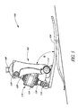
- FIG. 1 is a perspective view of a lower limb prosthesis having an ankle-motion-controlled foot unit according to one embodiment of the invention.
- FIG. 2 is a perspective view of the lower limb prosthesis of FIG. 1 , wherein a cover is removed to show inner components of the prosthesis.
- FIG. 3 is a side view of the lower limb prosthesis of FIG. 2 .
- FIG. 4 is a rear view of the lower limb prosthesis of FIG. 2 .
- FIG. 5 is a side view of the lower limb prosthesis of FIG. 1 with the cover shown partially removed, wherein the ankle-motion-controlled foot is adjusted to accommodate an incline.
- FIG. 6 is a side view of a lower limb prosthesis of FIG. 5 , wherein the ankle-motion-controlled foot is adjusted to accommodate a decline.
- FIG. 7 is a schematic drawing indicating the correlation between an ankle pivot point on an exemplifying embodiment of a prosthetic foot unit with the natural ankle joint of a human foot.
- FIG. 8 is a graph depicting the range of ankle motion of an exemplifying embodiment of a prosthetic or orthotic system during one full stride on a level surface.
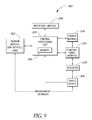
- FIG. 9 is a block diagram of an exemplifying embodiment of a control system architecture of a prosthetic or orthotic system having an ankle-motion-controlled foot.
- FIG. 10 is a table illustrating control signals usable to adjust the ankle angle of a prosthetic or orthotic system according to one embodiment of the invention.
- FIG. 11 is a graph depicting an exemplifying embodiment of the relationship between the control of a prosthetic or orthotic system and the motion of a corresponding sound limb.
- FIG. 12A is a perspective view of another embodiment of a lower limb prosthesis.
- FIG. 12B is a side view of the lower limb prosthesis of FIG. 12A .
- FIG. 12C is a cross-sectional view of the lower limb prosthesis of FIG. 12B along plane M-M.
- FIG. 13 is a perspective view of one embodiment of an actuator which may be used with the lower limb prosthesis of FIG. 12A .
- FIG. 14 is a side-view of the actuator of FIG. 13 .
- FIG. 15 is a rear view of the actuator of FIG. 13 .
- FIG. 16 is a top view of the actuator of FIG. 13 .
- FIG. 17 is a cross-sectional side view of the actuator of FIG. 13 .
- FIG. 18 is an exploded view of the actuator of FIG. 13 .
- FIG. 19 is a flow chart illustrating different phases of motion of the prosthesis shown in FIG. 12A .
- FIG. 20 is a disassembled view of a lower limb prosthesis having an ankle-motion-controlled foot unit according to another embodiment of the invention.
- FIG. 21 is a disassembled view of a sensor assembly usable with the lower limb prosthesis of FIG. 20 .
- FIG. 22 is a flowchart of an exemplifying embodiment of a terrain determination process 800 according to an embodiment of the invention.
- Some embodiments of the invention described herein relate generally to prosthetic and orthotic systems and, in particular, to prosthetic and orthotic devices having an ankle-motion-controlled foot. While the description sets forth various embodiment-specific details, it will be appreciated that the description is illustrative only and should not be construed in any way as limiting the invention. Furthermore, various applications of the invention, and modifications thereto, which may occur to those who are skilled in the art, are also encompassed by the general concepts described herein.
- prosthetic and “prosthesis” as used herein are broad terms and are used in their ordinary sense and refer to, without limitation, any system, device or apparatus usable as an artificial substitute or support for a body part.
- orthotic and “orthosis” as used herein are broad terms and are used in their ordinary sense and refer to, without limitation, any system, device or apparatus usable to support, align, prevent, protect, correct deformities of, immobilize, or improve the function of parts of the body, such as joints and/or limbs.
- ankle device as used herein is a broad term and is used in its ordinary sense and relates to any prosthetic, orthotic or ankle-assisting device.
- transtibial as used herein is a broad term and is used in its ordinary sense and relates to without limitation any plane, direction, location, or cross-section that is located at or below a knee joint of a body, including artificial knee joints.
- transfemoral as used herein is a broad term and is used in its ordinary sense and relates to without limitation any plane, direction, location, or cross-section that is located at or above a knee joint of a body, including artificial knee joints.
- sagittal as used herein is a broad term and is used in its ordinary sense and relates to any description, location, or direction relating to, situated in, or being in or near the median plane (i.e., the plane divides the body lengthwise into right and left halves) of the body or any plane parallel or approximately parallel thereto.
- a “sagittal plane” may also refer to any vertical anterior to posterior plane that passes through the body parallel or approximately parallel to the median plane and that divides the body into equal or unequal right and left sections.
- coronal as used herein is a broad term and is used in its ordinary sense and relates to any description, location, or direction relating to, situated in, or being in or near the plane that passes through the long axis of the body.
- a “coronal plane” may also refer to any plane that passes vertically or approximately vertically through the body and is perpendicular or approximately perpendicular to the median plane and that divides the body into anterior and posterior sections.
- FIG. 1 illustrates one embodiment of a lower limb prosthesis 100 having an ankle-motion-controlled foot with an attachment member.
- the prosthesis 100 comprises an attachment member, in the form of a lower limb member 102 , operatively coupled to a foot unit 104 .
- attachment member is a broad term and is used in its ordinary sense and in a prosthetic foot embodiment relates to, without limitation, any member that attaches either directly or indirectly to the foot unit 104 and is moveable in relation thereto, for example by a pivoting motion, and is used to attach the prosthesis 100 to a stump or intermediate prosthesis.
- the attachment member may take the form of a lower limb member in an ankle-prosthesis embodiment.
- the attachment member may be used to attach to and support a body part, such as with a brace, which also is moveably connected to a second member, such as a foot unit, which would also attach to and support a body part, such as the foot.
- the lower limb member 102 is a generally elongated member with a main longitudinal axis that extends in approximately a tibial direction, that is, a direction that extends generally along the axis of a natural tibia bone.
- FIG. 1 depicts the lower limb member 102 as being a generally vertical orientation.
- the lower limb member 102 may comprise multiple sections.
- the lower limb member 102 may comprise two elongated sections that extend approximately parallel in a tibial direction and that are connected together.
- the lower limb member 102 comprises a two-sided chamber having two substantially symmetrical parts to form a partially enclosed housing.
- the lower limb member 102 may comprise a hollow member, such as a tube-like structure.
- the lower limb member 102 may comprise elongated flat portions or rounded portions.
- the structure of the lower limb member 102 is not elongated.
- the lower limb member 102 may comprise a generally circular, cylindrical, half-circular, dome-shaped, oval or rectangular structure.
- a possible lower limb member is the ankle module and the structures described in U.S. patent application Ser. No. 10/742,455, filed Dec. 18, 2003, entitled “PROSTHETIC FOOT WITH ROCKER MEMBER,” and published on Jun. 23, 2005, as U.S. Patent Publication No. 20050137717A1, the entirety of which is hereby incorporated herein by reference and is to be considered as part of this specification.
- the lower limb member 102 is generally formed of a machine metal, such as aluminum, or a carbon fiber material. In other embodiments of the invention, the lower limb member 102 may comprise other materials that are suitable for prosthetic devices. In one embodiment, the lower limb member 102 advantageously has a height between approximately 12 and 15 centimeters. In other embodiments of the invention, the lower limb member 102 may have a height less than 12 centimeters or height greater than 15 centimeters depending on the size of the user and/or the intended use of the prosthesis 100 . For example, the lower limb member 102 may have a height of approximately 20 centimeters.
- the prosthesis 100 is configured such that the main longitudinal axis of the lower limb member 102 is substantially perpendicular to a lower surface of the foot unit 104 when the prosthesis 100 is in a resting position.
- the lower limb member 102 may be substantially perpendicular to a level ground surface when the foot unit 104 rests on the ground. Such a configuration advantageously provides a user with increased support and/or stability.
- the lower limb member 102 further comprises a cover 106 .
- the cover 106 houses and/or protects the inner components of the lower limb member 102 .
- the cover 106 may be rounded or may be shaped in the form of a natural human leg.
- the lower limb member 102 further comprises an attachment portion 108 to facilitate coupling of the lower limb member 102 .
- the attachment portion 108 of the lower limb member 102 couples the prosthesis 100 to a pylon 110 .
- the attachment portion 108 may be configured to couple the prosthesis 100 to a stump of an amputee or to another prosthetic device.
- FIG. 1 also depicts a control wire 112 usable to provide power to and/or communicate control signals to the prosthesis 100 .
- the foot unit 104 may comprise various types of prosthetic or orthotic feet. As illustrated in FIG. 1 , the foot unit 104 incorporates a design described in Applicant's co-pending U.S. patent application Ser. No. 10/642,125, entitled “LOW PROFILE PROSTHETIC FOOT,” filed Aug. 15, 2003, and published on Feb. 17, 2005, as U.S. Patent Publication No. 20050038524A1, the entirety of which is hereby incorporated by reference and is to be considered as part of this specification.
- the foot unit 104 may comprise a standard LP VARI-FLEX® unit available from ⁇ ssur.
- the foot unit 104 is configured to exert a proportional response to weight or impact levels on the foot unit 104 .
- the foot unit 104 may comprise shock absorption for comfortable loading of the heel and/or for returning expended energy.
- the foot unit 104 may comprise a full-length toe lever with enhanced flexibility so as to provide a stride length for the prosthetic limb that mimics the stride length of the healthy limb.
- the foot unit 104 may comprise a split-toe configuration, which facilitates movement on uneven terrain.
- the foot unit 104 may also include a cosmesis or a foot cover such as, for example, a standard Flex-Foot cover available from ⁇ ssur.
- FIG. 2 depicts the prosthesis 100 with the cover 106 removed.
- a lower end of the lower limb member 102 is coupled to the foot unit 104 at a pivot assembly 114 .
- the lower limb member 102 is coupled to an ankle plate of the foot unit 104 , which extends generally rearward and upward from a toe portion of the foot unit 104 .
- the pivot assembly 114 allows for angular movement of the foot unit 104 with respect to the lower limb member 102 .
- the pivot assembly 114 advantageously comprises at least one pivot pin.
- the pivot assembly 114 comprises a hinge, a multi-axial configuration, a polycentric configuration, combinations of the same or the like.
- the pivot assembly 114 is located on a portion of the foot unit 104 that is near a natural ankle location of the foot unit 104 .
- the pivot assembly 114 may be bolted or otherwise releasably connected to the foot unit 104 .
- FIG. 2 further depicts the prosthesis 100 having an actuator 116 .
- the actuator 116 advantageously provides the prosthesis 100 with the necessary energy to execute angular displacements synchronized with the amputee's locomotion.
- the actuator 116 may cause the foot unit 104 to move similar to a natural human foot.
- the lower end of the actuator 116 is coupled to the foot unit 104 at a first attachment point 118 .
- the foot attachment point 118 is advantageously located on the upper surface of the foot unit 104 on a posterior portion thereof.
- the upper end of the actuator 116 is coupled to the lower limb member 102 at a second attachment point 120 .
- the linear motion (or extension and contraction) of the actuator 116 controls, or actively adjusts, the angle between the foot unit 104 and the lower limb member 102 .
- FIG. 2 depicts the actuator 116 comprising a double-screw motor, wherein the motor pushes or pulls a posterior portion of the foot unit 104 with respect to the lower limb member 102 .
- the actuator 116 comprises other mechanisms capable of actively adjusting an angle, or providing for motion between, multiple members.
- the actuator 116 may comprise a single-screw motor, a piston cylinder-type structure, a servomotor, a stepper motor, a rotary motor, a spring, a fluid actuator, or the like.
- the actuator 116 may actively adjust in only one direction, the angle between the lower limb member 102 and the foot unit 104 .
- the weight of the user may also be used in controlling the angle caused by and/or the movement of the actuator 116 .
- FIG. 2 illustrates the actuator 116 in a posterior configuration, wherein the actuator 116 is located behind the lower limb member 102 .
- the actuator 116 may be used in an anterior configuration, wherein the actuator 116 is located in front of the lower limb member 102 .
- the actuator 116 comprises an auto adjusting ankle structure and incorporates a design, such as described in U.S. Pat. No. 5,957,981, the entirety of which is hereby incorporated by reference and is to be considered as a part of this specification.
- the particular configuration or structure may be selected to most closely imitate the movement and location of a natural human ankle joint and to facilitate insertion of the prosthesis 100 into an outer cosmesis.
- FIG. 2 further depicts control circuitry 122 usable to control the operation of the actuator 116 and/or the foot unit 104 .
- the control circuitry 122 comprises at least one printed circuit board (PCB).
- the PCB may further comprise a microprocessor.
- Software may also reside on the PCB so as to perform signal processing and/or control the movement of the prosthesis 100 .
- the prosthesis 100 includes a battery (not shown) that powers the control circuitry 122 and/or the actuator 116 .
- the battery comprises a rechargeable lithium ion battery that preferably has a power cycle of at least 12 to 16 hours. In yet other embodiments, the power cycle of the battery may be less than 12 hours or may be more than 16 hours.
- the battery comprises a lithium polymer battery, fuel cell technology, or other types of batteries or technology usable to provide power to the prosthesis 100 .
- the battery is removably attached to a rear surface of the lower limb member 102 , to other portions of the prosthesis 100 , or is located remote the prosthesis 100 .
- the prosthesis 100 may be connected to an external power source, such as through a wall adapter or car adapter, to recharge the battery.
- the prosthesis 100 is configured to lock in a neutral position, such as the lower limb member 102 being aligned generally vertical relative to a level ground surface when the foot unit 104 is resting on the level ground surface, when the battery is out of power or enters a low power stage. Such locking provides for operational safety, reliability, and/or stability for a user.
- the prosthesis 100 may also provide a battery status display that alerts the user as to the status (i.e., charge) of the battery.
- the prosthesis 100 locks into a substantially neutral position when the motion control functions of the prosthesis 100 are turned off or disabled by a user.
- a cosmesis material or other dressings may be used with the prosthesis 100 so as to give the prosthesis 100 a more natural look or shape.
- the cosmesis, dressings, or other filler material may be used to prevent contaminants, such as dirt or water, from contacting the components of the prosthesis 100 .
- FIG. 3 depicts a side view of the prosthesis 100 according to one embodiment of the invention.
- the actuator 116 further comprises a main housing 124 , a lower extendable portion 126 , and an upper extendable portion 128 .
- the lower extendable portion 126 couples the main housing 124 of the actuator 116 to the foot unit 104 at the first attachment point 118 .
- the upper extendable portion 128 couples the main housing 124 of the actuator 116 to the lower limb member 102 at the second attachment point 120 .
- the lower extendable portion 126 and/or the upper extendable portion 128 move into and/or out of the main housing 124 of the actuator 116 to adjust an angle between the foot unit 104 and the lower limb member 102 .
- extension of the lower extendable portion 126 and/or the upper extendable portion 128 causes an increase in the angle between the lower limb member 102 and the foot unit 104 .
- a contraction of the lower extendable portion 126 and/or the upper extendable portion 128 causes a decrease in the angle between the foot unit 104 and the lower limb member 102 .
- FIG. 4 illustrates a rear view of the prosthesis 100 depicted in FIGS. 1-3 .
- the cover 106 extends around the posterior portion of the prosthesis 100 to house at least a portion of the actuator 116 such that portions of the actuator 116 are not visible and/or not exposed to the environment.
- FIGS. 5 and 6 illustrate one embodiment of the prosthesis 100 as it adjusts to inclines and declines.
- the prosthesis 100 is depicted as adjusting to an incline.
- the actuator 116 extends so as to decrease an angle ⁇ between the lower limb member 102 and the foot unit 104 (or “dorsiflexion”).
- ⁇ an angle between the lower limb member 102 and the foot unit 104
- the angular range of motion of the prosthesis 100 is from about 0 to 10 degrees from the neutral position. Other embodiments may also facilitate exaggerated dorsiflexion during swing phase.
- FIGS. 5 and 6 further illustrate one embodiment of the attachment portion 108 .
- the attachment portion 108 provides alignment between the natural limb of the amputee and the prosthesis 100 and may be configured so as to decrease pressure peaks and shear forces.
- the attachment portion 108 may be configured to attach to another prosthesis, to the stump of the amputee, or to another component.
- the attachment portion 108 comprises a socket connector.
- the socket connector may be configured to receive a 32 mm-thread component, a male pyramid type coupler, or other components.
- the attachment portion 108 may also comprise, or be configured to receive, a female pyramid adapter.
- FIG. 7 further illustrates a schematic drawing indicating the correlation between an ankle pivot point on a prosthetic foot unit 204 with the natural human ankle joint of a foot.
- the prosthetic foot unit 204 comprises a pivot assembly 214 that corresponds to an ankle joint 240 of a human foot 242 .
- the pivot assembly 114 is located near the mechanical ankle center of rotation of the prosthesis 100 .
- the prosthesis 100 is configured to provide dampening or passive, soft resistance to changes in the angle between the lower limb member 102 and the foot unit 104 .
- An example of a system for controlling such dampening is disclosed in U.S. Pat. No. 6,443,993, which is hereby incorporated herein by reference and is to be considered as a part of this specification.
- dampening of the prosthesis 100 may be provided by hydraulic dampers.
- other components or devices that are known in the art may be used to provide dampening for the prosthesis 100 .
- the dampers may be dynamically controlled, such as through an electronic control system, which is discussed in more detail below.
- the dampers may be controlled through mechanical and/or fluid-type structures.
- the above-described systems may be implemented in prosthetic or orthotic systems other than transtibial, or below-the-knee, systems.
- the prosthetic or orthotic system may be used in a transfemoral, or above-the-knee, system, such as is disclosed in U.S. Provisional Application No. 60/569,512, filed May 7, 2004, and entitled “MAGNETORHEOLOGICALLY ACTUATED PROSTHETIC KNEE;” U.S. Provisional Application No. 60/624,986, filed Nov. 3, 2004, and entitled “MAGNETORHEOLOGICALLY ACTUATED PROSTHETIC KNEE;” and U.S. patent application Ser. No.
- the prosthetic or orthotic system may include both a prosthetic or orthotic ankle and/or a prosthetic or orthotic knee.
- FIG. 9 illustrates a block diagram of one embodiment of a system architecture of a control system 300 for an ankle-motion-controlled foot.
- the control system 300 is usable by the lower limb prosthesis 100 depicted in FIGS. 1-6 .
- the control system 300 is usable by an orthotic system or a rehabilitation system having an ankle-motion-controlled foot, or other motion-controlled limb.
- the control system 300 is based on a distributed processing system wherein the different functions performed by the prosthetic or orthotic system, such as sensing, data processing, and actuation, are performed or controlled by multiple processors that communicate with each other.
- the control system 300 depicted in FIG. 9 processes data received from the sensing module 302 with the CPU 305 .
- the CPU 305 communicates with the control drive module 310 to control the operation of the actuator 316 so as to mimic natural ankle movement by the ankle device 304 .
- the control system 300 may predict how the ankle device 304 may need to be adjusted in order to accommodate movement by the user.
- the CPU 305 may also receive commands from a user and/or other device through the interface module 308 .
- the power module 318 provides power to the other components of the control system 300 . Each of these components is described in more detail below.
- the sensor module 302 advantageously includes a printed circuit board housing, multiple sensors, such as accelerometers, which each measures an acceleration of the ankle device 304 in a different axis.
- the sensor module 302 may comprise three accelerometers that measure acceleration of the ankle device 304 in three substantially, mutually perpendicular axes. Sensors of the type suitable for the sensor module 302 are available from, for example, Dynastream Innovations, Inc. (Alberta, Canada).
- the sensor module 302 may include one or more other types of sensors in combination with, or in place of, accelerometers.
- the sensor module 302 may include a gyroscope configured to measure the angular speed of body segments and/or the ankle device 304 .
- the sensor module 302 includes a plantar pressure sensor configured to measure, for example, the vertical plantar pressure of a specific underfoot area.
- the sensor module 302 may include one or more of the following: kinematic sensors, single-axis gyroscopes, single- or multi-axis accelerometers, load sensors, flex sensors or myoelectric sensors that may be configured to capture data from the user's natural limb.
- the sensor module 302 may be used to capture information relating to, for example, one or more of the following: the position of the ankle device 304 with respect to the ground; the inclination angle of the ankle device 304 ; the direction of gravity with respect to the position of the ankle device 304 ; information that relates to a stride of the user, such as when the ankle device 304 contacts the ground (e.g., “heel strike”), is in mid-stride, or leaves the ground (e.g., “toe-off”), the distance from the ground of the prosthesis 100 at the peak of the swing phase (i.e., the maximum height during the swing phase); the timing of the peak of the swing phase; and the like.
- a stride of the user such as when the ankle device 304 contacts the ground (e.g., “heel strike”), is in mid-stride, or leaves the ground (e.g., “toe-off”), the distance from the ground of the prosthesis 100 at the peak of the swing phase (i.
- the sensor module 302 is configured to detect gait patterns and/or events. For example, the sensor module 302 may determine whether the user is in a standing/stopped position, is walking on level ground, is ascending and/or descending stairs or sloped surfaces, or the like. In other embodiments, the sensor module 302 is configured to detect or measure the heel height of the ankle device 304 and/or determine a static shank angle in order to detect when the user is in a sitting position.
- the sensor module 302 is further configured to measure environmental or terrain variables including one or more of the following: the characteristics of the ground surface, the angle of the ground surface, the air temperature and wind resistance.
- the measured temperature may be used to calibrate the gain and/or bias of other sensors.
- the sensor module 302 captures information about the movement and/or position of a user's natural limb, such as a healthy leg. In such an embodiment, it may be preferable that when operating on an incline or a decline, the first step of the user be taken with the healthy leg. Such would allow measurements taken from the natural movement of the healthy leg prior to adjusting the ankle device 304 .
- the control system 300 detects the gait of the user and adjusts the ankle device 304 accordingly while the ankle device 304 is in a swing phase of the first step. In other embodiments of the invention, there may be a latency period in which the control system 300 requires one or two strides before being able to accurately determine the gait of the user and to adjust the ankle device 304 appropriately.
- the sensor module 302 has a default sampling rate of 100 hertz (Hz). In other embodiments, the sampling rate may be higher or lower than 100 Hz or may be adjustable by a user, or may be adjusted automatically by software or parameter settings. In addition, the sensor module 302 may provide for synchronization between types of data being sensed or include time stamping. The sensors may also be configured so as to have an angular resolution of approximately 0.5 degrees, allowing for fine adjustments of the ankle device 304 .
- the sensor module 302 is configured to power down into a “sleep” mode when sensing is not needed, such as for example, when the user is relaxing while in a sitting or reclining position. In such an embodiment, the sensor module 302 may awake from the sleep state upon movement of the sensor module 302 or upon input from the user. In one embodiment, the sensor module 302 consumes approximately 30 milliamps (mA) when in an “active” mode and approximately 0.1 mA when in a “sleep” mode.
- mA milliamps
- FIG. 9 illustrates the sensor module 302 communicating with the CPU 305 .
- the sensor module 302 advantageously provides measurement data to the CPU 305 and/or to other components of the control system 300 .
- the sensor module 302 is coupled to a transmitter, such as, for example, a Bluetooth® transmitter, that transmits the measurements to the CPU 305 .
- a transmitter such as, for example, a Bluetooth® transmitter
- other types of transmitters or wireless technology may be used, such as infrared, WiFi®, or radio frequency (RF) technology.
- RF radio frequency
- wired technologies may be used to communicate with the CPU 305 .
- the sensor module 302 sends a data string to the CPU 305 that comprises various types of information.
- the data string may comprise 160 bits and include the following information:
- the CPU 305 advantageously processes data received from other components of the control system 300 .
- the CPU 305 processes information relating to the gait of the user, such as information received from the sensor module 302 , determines locomotion type (i.e., gait pattern), and/or sends commands to the control drive module 310 .
- the data captured by the sensor module 302 may be used to generate a waveform that portrays information relating to the gait or movement of the user. Subsequent changes to the waveform may be identified by the CPU 305 to predict future movement of the user and to adjust the ankle device 304 accordingly.
- the CPU 305 may detect gait patterns from as slow as 20 steps per minute to as high as 125 steps per minute. In other embodiments of the invention, the CPU 305 may detect gait patterns that are slower than 20 steps per minute or higher than 125 steps per minute.
- the body of TABLE 1 identifies the source of data used by the CPU 305 in controlling, or actively adjusting, the actuator 316 and the ankle device 304 during the transition from a first state to a second state; wherein “N” indicates that no additional data is needed for the state transition; “L” indicates that the CPU 305 uses transition logic to determine the adjustments to the ankle device 304 during the state transition; and “I” indicates the CPU receives data from an interface (e.g., interface module 308 , external user interface, electronic interface or the like).
- Transition logic usable with embodiments of the invention may be developed by one with ordinary skill in the relevant art. Examples of transition logic used in similar systems and methods to embodiments of the present invention are disclosed in U.S. Provisional Application No.
- the above described states in TABLE 1 are predefined states of the ankle device 304 .
- the “OFF” state may indicate that the functions of the ankle device 304 and the actuator 316 are in an off or suspend mode.
- the “REEL_HEIGHT_CAL” state relates to the measuring of a heel height from a static sensor angle such as, for example, when the ankle device 304 is not in motion.
- the “SENSOR_CAL” state relates to surface angle calibration when the user is walking on a level surface.
- the “NEUTRAL” state relates to when the ankle device 304 is locked in a substantially fixed position.
- the “WALK” state relates to when the user is walking, such as on a level or sloped surface.
- other states are usable with the ankle device 304 in place of, or in combination with, the states identified in TABLE 1.
- states may be defined that correspond to lying down, cycling, climbing a ladder or the like.
- the CPU 305 and/or control system 300 may process or derive data from sources other than those listed in TABLE 1.
- the CPU 305 may perform a variety of other functions.
- the CPU 305 may use information received from the sensor module 302 to detect stumbling by the user.
- the CPU 305 may function as a manager of communication between the components of the control system 300 .
- the CPU 305 may act as the master device for a communication bus between multiple components of the control system 300 .
- the CPU 305 communicates with the power module 318 .
- the CPU 305 may provide power distribution and/or conversion to the other components of the control system 300 and may also monitor battery power or battery life.
- the CPU 305 may function so as to temporarily suspend or decrease power to the control system 300 when a user is in a sitting or a standing position.
- the CPU 305 may also process error handling, such as when communication fails between components, an unrecognized signal or waveform is received from the sensor module 302 , or when the feedback from the control drive module 310 or the ankle device 304 causes an error or appears corrupt.
- the CPU 305 uses or computes a security factor when analyzing information from the sensor module 302 and/or sending commands to the control drive module 310 .
- the security factor may include a range of values, wherein a higher value indicates a higher degree of certainty associated with a determined locomotion type of the user, and a lower security factor indicates a lower degree of certainty as to the locomotion type of the user.
- adjustments are not made to the ankle device 304 unless the locomotion type of the user is recognized with a security factor above a predetermined threshold value.
- the CPU 305 includes modules that comprise logic embodied in hardware or firmware, or that comprise a collection of software instructions written in a programming language, such as, for example C++.
- a software module may be compiled and linked into an executable program, installed in a dynamic link library, or may be written in an interpretive language such as BASIC.
- software modules may be callable from other modules or from themselves, and/or may be invoked in response to detected events or interrupts.
- Software instructions may be embedded in firmware, such as an EPROM or EEPROM.
- hardware modules may be comprised of connected logic units, such as gates and flip-flops, and/or may be comprised of programmable units, such as programmable gate arrays or processors.
- FIG. 9 further depicts CPU 305 including a memory 306 for storing instructions and/or data.
- the memory 306 may store one or more of the following types of data or instructions: an error log for the other components of the control system 300 ; information regarding gait patterns or curves; information regarding past activity of the user (e.g., number of steps); control parameters and set points; information regarding software debugging or upgrading; preprogrammed algorithms for basic movements of the prosthetic or orthotic system; calibration values and parameters relating to the sensor module 302 or other components; instructions downloaded from an external device; combinations of the same or the like.
- the memory 306 may comprise any buffer, computing device, or system capable of storing computer instructions and/or data for access by another computing device or a computer processor.
- the memory 306 is a cache that is part of the CPU 305 .
- the memory 306 is separate from the CPU 305 .
- the memory 306 comprises random access memory (RAM) or may comprise other integrated and accessible memory devices, such as, for example, read-only memory (ROM), programmable ROM (PROM), and electrically erasable programmable ROM (EEPROM).
- the memory 306 comprises a removable memory, such as a memory card, a removable drive, or the like.
- the CPU 305 may also be configured to receive through the interface module 308 user- or activity-specific instructions from a user or from an external device.
- the CPU 305 may also receive updates to already existing instructions.
- the CPU 305 may communicate with a personal computer, a personal digital assistant, or the like so as to download or receive operating instructions.
- Activity-specific instructions may include, for example, data relating to cycling, driving, ascending or descending a ladder, adjustments from walking in snow or sand, or the like.
- the interface module 308 comprises an interface that the user accesses so as to control or manage portions or functions of the prosthetic or orthotic system.
- the interface module 308 is a flexible keypad having multiple buttons and/or multiple light emitting diodes (LEDs) usable to receive information from and/or convey information to a user.
- the LEDs may indicate the status of a battery or may convey a confirmation signal to a user.
- the interface module 308 may be advantageously located on the ankle device 304 .
- the interface module 308 may comprise a USB connector usable for communication to an external computing device, such as a personal computer.
- the interface module 308 comprises an on/off switch.
- the interface module 308 may receive input regarding the user-controlled heel height or a forced relaxed mode of the prosthetic or orthotic system.
- the user may adjust the type of response desired of the prosthesis or enable/disable particular functions of the ankle device 304 .
- the input from the user may be entered directly via the interface module 308 , such as through actuating a button, or user input may be received via a remote control.
- the interface module 308 may comprise a touch screen, buttons, switches, a vibrator, an alarm, or other input-receiving or output structures or devices that allow a user to send instructions to or receive information from the control system 300 .
- the interface module 308 comprises an additional structure, such as a plug, for charging a battery powering the control system 300 , such as at home or in a vehicle.
- the interface module 308 may also communicate directly or indirectly with components of the control system 300 other than the CPU 305 .
- the control drive module 310 is used to translate high-level plans or instructions received from the CPU 305 into low-level control signals to be sent to the actuator 316 .
- the control drive module 310 comprises a printed circuit board that implements control algorithms and tasks related to the management of the actuator 316 .
- the control drive module 310 may be used to implement a hardware abstraction layer that translates the decision processes of the CPU 305 to the actual hardware definition of the actuator 316 .
- the control drive module 310 may be used to provide feedback to the CPU 305 regarding the position or movement of the actuator 316 or ankle device 304 .
- the control drive module 310 may also be used to adjust the actuator 316 to a new “neutral” setting upon detection by the CPU 305 that the user is traveling on an angled surface.
- control drive module 310 is located within the ankle device 304 . In other embodiments, the control drive module 310 may be located on the outside of the ankle device 304 , such as on a socket, or remote to the ankle device 304 .
- the actuator 316 provides for the controlled movement of the ankle device 304 .
- the actuator 316 functions similarly to the actuator 116 described with respect to FIGS. 1-6 , which actuator 116 controls the ankle motion of the prosthesis 100 .
- the actuator 316 may be configured to control the motion of an orthotic device, such as a brace or other type of support structure.
- the ankle device 304 comprises any structural device that is used to mimic the motion of a joint, such as an ankle, and that is controlled, at least in part, by the actuator 316 .
- the ankle device 304 may comprise a prosthetic device or an orthotic device.
- the power module 318 includes one or more sources and/or connectors usable to power the control system 300 .
- the power module 318 is advantageously portable, and may include, for example, a rechargeable battery, as discussed previously.
- the power module 318 communicates with the control drive module 310 and the CPU 305 .
- the power module 318 communicates with other control system 300 components instead of, or in combination with, the control drive module 310 and the CPU 305 .
- the power module 318 communicates directly with the sensor module 302 .
- the power module 318 may communicate with the interface module 308 such that a user is capable of directly controlling the power supplied to one or more components of the control system 300 .
- FIG. 9 depicts two types of links: primary communication links, which are depicted as solid lines between the components, and secondary communication links, which are depicted as dashed lines.
- primary communication links operate on an established protocol.
- the primary communication links may run between physical components of the control system 300 .
- Secondary communication links may operate on a different protocol or level than the primary communication links. For example, if a conflict exists between a primary communication link and a secondary communication link, the data from the primary communication link will override the data from the secondary communication link.
- the secondary communication links are shown in FIG. 9 as being communication channels between the control system 300 and the environment.
- the modules may communicate with each other and/or the environment through other types of communication links or methods. For example, all communication links may operate with the same protocol or on the same level of hierarchy.
- the components of the control system 300 may be integrated in different forms.
- the components can be separated into several subcomponents or can be separated into more devices that reside at different locations and that communicate with each other, such as through a wired or wireless network.
- the modules may communicate through RS232 or serial peripheral interface (SPI) channels. Multiple components may also be combined into a single component. It is also contemplated that the components described herein may be integrated into a fewer number of modules. One module may also be separated into multiple modules.
- control system 300 may include more or fewer components than described above.
- the control system 300 may further include an actuator potentiometer usable to control, or fine-tune, the position of the actuator 316 .
- the user may also use the actuator potentiometer to adjust the heel height of the ankle device 304 .
- the actuator potentiometer communicates with the CPU 305 .
- the control system 300 may include a vibrator, a DC jack, fuses, combinations of the same, or the like.
- FIG. 10 is a table that depicts possible control signals that may be involved in adjusting the ankle angle of a prosthetic or orthotic device when a user is transitioning between different states, or types of locomotion, according to one embodiment of the invention.
- the states listed in a column 402 identify a first state of the user
- the states listed in a row 404 identify a second state of the user, or the state to which the user is transitioning.
- the remainder of the table identifies possible actions that may be taken by the prosthetic or orthotic device with respect to the ankle angle.
- “User set point” is the neutral, or default, value that may be set during shoe heel height adjustment.
- the angles specified are examples of changes to the ankle angle of the prosthetic or orthotic device.
- the ankle angle may be adjusted to the angle of the stairs, such as for example, ⁇ 10 degrees (or 10 degrees dorsiflexion).
- Ankle angles given in the “Incline (up)” and “Decline” columns reflect threshold levels of ankle angle adjustment depending on the angle of the incline.
- the following table illustrates possible ankle motion strategies for one embodiment of the invention.
- the first column of TABLE 2 lists different types of locomotion types or gait patterns that may be frequently detected.
- the second column of TABLE 2 identifies examples of ankle angle adjustment of the prosthetic or orthotic device during the swing phase of each of the identified locomotion types.
- FIG. 11 depicts a graph that illustrates the interaction and relationship between the control of a prosthetic or orthotic leg and the measurements taken from a healthy, sound leg.
- FIG. 11 depicts the movement of a prosthetic or orthotic leg and a healthy leg during one full stride of a user.
- the graph shows the prosthetic or orthotic leg as being in a “stance” position or being planted on a surface, such as the ground.
- the ankle angle of the prosthetic or orthotic leg may decrease (dorsiflexion).
- the ankle angle of the prosthetic or orthotic leg may then increase (plantarflexion) to facilitate natural stride movements.
- the ankle angle of the prosthetic or orthotic leg is not actively adjusted during the stance phase.
- the healthy leg may be in a swinging position, wherein the healthy leg is not in contact with the ground. Between the points of approximately 40% and 60%, both legs are in contact with the ground.
- the prosthetic or orthotic leg is in a swinging position, and the healthy leg is in contact with the ground.
- the graph in FIG. 11 shows that the ankle angle of the prosthetic or orthotic leg is adjusted during the swing phase. This angle adjustment may be based on previous measurements of the healthy leg during the swing phase of the healthy leg. In one embodiment, during the beginning portion of the swing phase of the prosthetic or orthotic leg, the ankle angle of the prosthetic or orthotic leg may decrease. This allows, for example, a toe portion of the prosthetic or orthotic leg to clear stairs. Toward the latter portion of the swing phase of the prosthetic or orthotic leg, the ankle angle of the prosthetic or orthotic leg may then increase before contacting the ground. In other embodiments, the angle adjustment is based on readings taken by sensors on the prosthetic side.
- FIG. 11 is illustrative of the functioning of one embodiment of the invention under certain conditions. Other embodiments or circumstances may require a longer or shorter stance or swing phase and require other adjustments to the angle of the ankle portion of the prosthetic leg.
- FIGS. 12A-12C illustrate another embodiment of a lower limb prosthesis 100 ′ configured to be attached to a human limb.
- the lower limb prosthesis 100 ′ is similar to the lower limb prosthesis 100 illustrated in FIG. 2 , except as noted below.
- the reference numerals used to designate the various components of the lower limb prosthesis 100 ′ are identical to those used for identifying the corresponding components of the lower limb prosthesis 100 in FIG. 2 , except that a “′” has been added to the reference numerals.
- the lower limb prosthesis 100 ′ comprises a first portion 102 ′ coupled to a second portion 104 ′, wherein the portions 102 ′, 104 ′ are moveable relative to each other to mimic a natural human joint.
- the first portion is a lower limb member 102 ′ and the second portion is a prosthetic foot unit 104 ′ operatively coupled to the lower limb member 102 ′ to mimic a natural human ankle joint.
- the foot unit 104 ′ includes a heel portion 104 a ′ at a rear end of the foot unit 104 ′ and a toe portion 104 b ′ at a front end of the foot unit 104 ′.
- the heel and toe portions 104 a ′, 104 b ′ can be unitary. In another embodiment, the heel and toe portions 104 a ′, 104 b ′ can be separate components fastened to each other via, for example, bolts, screws, adhesives and the like.
- the prosthetic foot unit 104 ′ is an LP VARI-FLEX® prosthetic foot commercially available from ⁇ ssur. However, the foot unit 104 ′ can have other configurations or designs.
- the first and second portions can be an upper leg member and a lower leg member, respectively, which are coupled to mimic a natural human knee joint.
- the lower limb prosthesis 100 ′ may also comprise a frame 106 ′ extending between the foot unit 104 ′ and the lower limb member 102 ′.
- an attachment portion 108 ′ of the lower limb member 102 ′ facilitates the coupling of the lower limb member 102 ′ to another member, such as, for example, the pylon 110 depicted in FIGS. 1-4 .
- the attachment portion 108 ′ is a pyramid.
- the lower limb member 102 ′, or support member couples to the foot unit 104 ′ at its lower end via a pivot assembly 114 ′, which is attached to the prosthetic foot unit 104 ′.
- the pivot assembly 114 ′ is attached at about the rear 1 ⁇ 3 of the foot unit 104 ′.
- the pivot assembly 114 ′ can be attached at other locations on the foot unit 104 ′.
- the pivot assembly 114 ′ mimics a natural human ankle joint.
- a cover 106 b ′ is disposed about an actuator 500 of the lower limb prosthesis 100 ′ to substantially protect the actuator 500 and inhibit the intrusion of foreign matter.
- the lower limb prosthesis 100 ′ may also include a control wire, such as the control wire 112 depicted in FIGS. 1-4 , to provide power to and/or communicates control signals to the prosthesis 100 ′.
- the actuator 500 provides the prosthesis 100 ′ with the necessary energy to execute angular displacements synchronized with an amputee's locomotion.
- the actuator 500 couples the first and second portions 102 ′, 104 ′ of the prosthesis 100 ′ together, which in the illustrated embodiment correspond to the lower limb member 102 ′ and the prosthetic foot unit 104 ′.
- the actuator is configured to adjust an angle between the lower limb member 102 ′ and the foot unit 104 ′.
- the actuator 500 couples to the foot unit 104 ′ and the lower limb member 102 ′ at first and second attachment points 118 ′, 120 ′, respectively.
- the prosthesis can include control circuitry to control the operation of the actuator 500 , such as, for example, the control circuitry 122 depicted in FIGS. 2 and 3 .
- FIGS. 13-18 illustrate one embodiment of an actuator 500 that may be used with the lower limb prosthesis 100 ′ discussed above.
- the actuator 500 preferably comprises a stator or top unit 510 having an attachment end 512 and a bottom end 514 .
- the attachment end 512 is a C-shaped clamp (see FIG. 15 ) having a first opening 512 a and a second opening 512 b aligned along a first axis X 1 that extends generally perpendicular to a longitudinal axis Y of the actuator 500 .
- the attachment end 512 can have other suitable configurations.
- the openings 512 a , 512 b are preferably sized to receive a fastener therethrough, such as a bolt, screw, or pin (not shown), to allow the top unit 510 to be fastened to, for example, the upper end of the lower limb member 102 ′ at the second attachment point 120 ′.
- a fastener such as a bolt, screw, or pin (not shown)
- the bottom end 514 of the top unit 510 preferably has a circumferential wall 514 a and a bottom surface 516 .
- the bottom surface 516 curves from the circumferential wall 514 a toward a center of the bottom surface 516 .
- the bottom surface 516 preferably includes a recess portion 518 located generally at the center of the bottom surface 516 .
- the recess portion 518 on the bottom surface 516 of the top unit 510 is preferably sized to receive a ball bearing 522 therein, as further discussed below.
- the circumferential wall 514 a includes a protrusion 520 that extends outward from the wall 514 a .
- the protrusion 520 extends substantially along the entire circumference of the wall 514 a .
- the protrusion 520 can be a plurality of protrusions positioned at discrete locations about the circumference of the wall 514 a.
- the actuator 500 also comprises a first elongate member or rotor 530 with a body extending from a top end 530 a to a bottom end 530 b along a length 532 , and having a diameter 534 .
- the length 532 is between about 25 mm and about 70 mm.
- the diameter 534 is between about 12 mm and about 40 mm. More preferably, the diameter 534 is about 17 mm.
- the rotor 530 has a circumferential flange 536 at the top end 530 a , the flange 536 having a diameter greater than the diameter 534 of the body.
- the top end 530 a has an outer surface 537 that curves generally upward from the circumferential flange toward a center 537 a of the surface 537 .
- the surface 537 defines a recessed portion 538 generally disposed at the center 537 a thereof.
- the recessed portion 538 is preferably contoured to receive the ball bearing 522 therein, such that the ball bearing 522 couples the top unit 510 to the rotor 530 .
- the top unit 510 and the rotor 530 couple to each other solely via the ball bearing 522 .
- the ball bearing 522 is a single ball bearing. However, other suitable bearings can be used.
- a thrust bearing is disposed between the top unit 510 and the rotor 530 .
- the rotor 530 is preferably an elongate nut defining a hollow central portion 539 , which defines a wall 539 a with threads 540 disposed along at least a portion the length of the wall 539 a.
- the ball bearing 522 preferably couples the top unit 510 to the first elongate member 530 .
- the curvature of the surface 537 of the rotor 530 and the curvature of the bottom surface 516 of the top unit 510 define a gap 541 therebetween.
- the gap 541 extends preferably circumferentially about the center 537 a of the surface 537 .
- at least one magnet 542 is disposed in the gap 541 and attached to the surface 537 via, for example, an adhesive.
- a plurality of magnets 542 are disposed about the center 537 a of the surface 537 .
- an annular magnet (not shown) can be disposed on the surface 537 , with the annulus of the magnet aligned with the center 537 a .
- the magnets 542 are preferably configured to exert a magnetic force on the top unit 510 and the rotor 530 , so that the force draws the top unit 510 and the rotor 530 toward each other.
- the actuator 500 also includes a retainer 550 having a height 551 and a wall 552 defining an inner diameter 554 .
- the retainer 550 includes a flange 556 having an inner portion 556 a extending radially inward from the wall 552 and an outer portion 556 b extending radially outward from the wall 522 , wherein the inner and outer portions 556 a , 556 b are preferably disposed at a bottom end of the wall 552 .
- the illustrated embodiment shows the flange 556 as being continuous around the circumference of the retainer 550
- the flange 556 can instead be a plurality of flange members disposed at discrete locations about the circumference of the retainer 556 .
- the inner diameter 554 of the retainer 550 is sized to receive the rotor 530 and the top unit 510 therein.
- the inner diameter 554 of the retainer 550 is preferably at least slightly greater than the diameter of the flange 536 of the rotor 530 , so that the flange 536 of the rotor 530 does not engage the wall 552 of the retainer 550 .
- the inner diameter 554 of the retainer 550 is preferably at least slightly greater than the diameter of at least a portion of the circumferential wall 514 a of the top unit 510 .
- the protrusions 520 on the circumferential wall 514 a of the top unit 510 preferably engage a portion of the wall 552 of the retainer 550 , such that the top unit 510 and the retainer 550 are coupled to each other.
- rotor 530 rotates about, and translates along, the longitudinal axis Y, as further discussed below.
- the rotor 530 remains coupled to the top unit 510 via the ball bearing 522 , but selectively moves in and out of contact with the retainer 550 via the inner flange 556 a , as further described below.
- the rotor 530 moves between contact with the top unit 510 , via the ball bearing 522 , and contact with the retainer 550 via the inner flange 556 a.
- the magnets 560 a , 560 b are magnetized rings with 24 poles. Additionally, as shown in FIG. 17-18 , a spacer 568 is disposed between the first and second magnets 560 a , 560 b . Preferably, the spacer 568 also has a diameter greater than the diameter 534 of the rotor 530 , so that the spacer 568 fits about the rotor 530 . Though the illustrated embodiment depicts two magnets 560 a , 560 b and one spacer 568 , one of ordinary skill in the art will recognize that any number of magnets and spacers can be used.
- the actuator 500 also comprises a sleeve 570 with a cylindrical body 571 having a length 572 and a diameter 574 such that the sleeve 570 fits about the rotor 530 .
- the length 572 is between about 10 mm and about 70 mm, and more preferably about 20 mm.
- the diameter 574 is preferably between about 12 mm and about 40 mm, and more preferably about 17 mm.
- the sleeve 570 has an inner diameter greater than the diameter 534 of the first elongate member 530 , and has an outer diameter that is smaller than the inner diameter of the first and second magnets 560 a , 560 b and the spacer 568 .
- the first and second magnets 560 a , 560 b and the spacer 568 fit about the sleeve 570 , which in turn fits about the rotor 530 .
- the rotor 530 , sleeve 570 , magnets 560 a , 560 b are disposed substantially adjacent each other.
- the sleeve 570 also has a lip 576 that extends circumferentially about the sleeve 570 .
- the lip 576 extends continuously around the sleeve 570 at a radial distance away from a surface of the sleeve 570 substantially equal to a thickness of at least one of the first and second magnets 560 a , 560 b .
- the lip 576 is preferably positioned a distance away from a top end of the sleeve 570 so as to support the first and second magnets 560 a , 560 b and the spacer 568 about the sleeve 570 so that the first and second magnets 560 a , 560 b and the spacer 568 do not extend past the top end of the sleeve 570 .
- the actuator 500 also comprises a motor 580 .
- the motor 580 has a height 582 and an inner surface 586 with an inner diameter 584 , such that the motor 580 can be disposed about the rotor 530 .
- the motor has a length of between about 10 mm and about 60 mm, and more preferably about 25 mm.
- the inner diameter 584 of the motor 580 is preferably between about 15 mm and about 50 mm. In a preferred embodiment, the diameter 584 of the motor 580 is about 22 mm. As illustrated in FIG.
- the motor 580 extends about the rotor 530 , such that the sleeve 570 , the first and second magnets 560 a , 560 b and the spacer 568 are disposed between the rotor 530 and the inner diameter 584 of the motor 580 .
- the motor 580 preferably comprises windings configured to rotate the rotor 530 via the magnets 560 a , 560 b .
- the motor 580 is a stepper motor.
- the motor 580 can be a DC motor, a piezo-electric motor, a DC brushless motor, and a servo motor.
- the actuator also comprises an o-ring 590 and a roller bearing 600 disposed between the motor 580 and a cover portion 610 having a protruding portion 612 .
- the cover 610 preferably houses the motor 580 therein when the actuator 500 is fully assembled.
- a bellows 620 is preferably disposed adjacent a bottom end of the cover 610 . The bellows 620 advantageously inhibits the entry of foreign particles, such as dust and water, into contact with the motor 580 and a second elongate member 630 of the actuator 500 .
- the second elongate member 630 extends along a length 632 and has a diameter 634 .
- the second elongate member 630 is a screw with threads 636 along a portion of the length 632 .
- the screw 630 has an attachment portion 638 at a bottom end thereof with an opening 638 a that extends therethrough along an axis X 2 generally orthogonal to the longitudinal axis Y of the actuator 500 .
- the opening 638 a is preferably sized to receive a fastener therethrough, such as a bolt, a screw or a pin. Accordingly, the attachment portion 638 can be fastened to, for example, the prosthetic foot unit 104 ′ at the first attachment point 118 ′.
- the threads 636 of the screw 630 are adapted to threadingly engage the threads 540 on the nut 530 .
- the threads 636 , 540 on the screw 630 and the nut 530 , respectively are designed to be on the boundary of a self-locking coupling.
- the threads 636 , 540 of the nut 530 and the screw 630 are trapezoidal threads.
- the threads 636 , 540 can be ACME centralized threads with a working diameter of about 14 mm, a pitch of about 2 mm, and about two leads. However, any suitable thread type can be used.
- the threads 636 , 540 are made of Aluminum Bronze and Stainless Steel. However, other suitable metals and alloys can be used.
- the threads 540 in the nut 530 are cut, while the threads 636 in the screw 630 and ground and coated with a coating, such as a permanent oil coating.
- the thread lengths in the nut 530 are configured to provide minimum friction during operation of the actuator 500 , while delivering optimum support and strength to the actuator 500 .
- the threads 540 , 636 of the nut 530 and the screw 630 can have other configurations and be made of other materials to provide a desired performance characteristic.
- the material and coating of the threads, as well as the pitch, working diameter, and number of leads can be varied to provide a different interface friction between the threads 636 , 540 .
- the pitch and configuration of the threads 636 , 530 can be chosen so that a load applied (e.g., along the longitudinal axis Y) to the screw 630 and/or nut 530 assembly will not initiate a self-generated movement of the actuator 500 . That is, the pitch and configuration of the threads 636 , 530 generate a friction force therebetween that is large enough to inhibit the relative rotation of the nut 530 and the screw 630 .
- the pitch and configuration of the threads 636 , 530 can be chosen so that a load applied to the screw 630 and/or nut 530 along the longitudinal axis Y will initiate a self-generated movement of the actuator 500 .
- the screw 630 preferably has a hollow portion 640 extending along a portion of the length 632 .
- the hollow portion 640 reduces the weight of the screw 630 , thereby reducing the weight of the actuator 500 as a whole.
- an adoption ring 650 is disposed about the screw 630 , wherein the ring 650 couples with the bottom end of the bellows 620 .
- the actuator 500 has a compact assembly. As discussed above, the motor 580 is disposed about the rotor 530 , which is disposed about the elongate member or screw 630 . Accordingly, the actuator 500 takes up less space and can have a lower height than other designs. In one preferred embodiment, the actuator 500 has a height of between about 40 mm to about 70 mm in a collapsed configuration, and a height of between about 65 mm to about 130 mm in a fully extended configuration. Additionally, the hollow portion 640 of the screw 630 advantageously reduces the weight of the actuator 500 .
- the actuator 500 advantageously minimizes friction between the stator or top unit 510 and the rotor or nut 530 .
- the ball bearing 522 disposed between the top unit 510 and the nut 530 inhibits the generation of a friction force between the top unit 510 and the nut 530 , thereby allowing the nut 530 to rotate generally freely relative to the top unit 510 .
- the magnets 542 draw the nut 530 toward the top unit 510 , as discussed above. Such a magnetic force lifts the nut 530 from engagement with the inner flange 556 a of the retainer 550 , thereby inhibiting the generation of friction between the retainer 550 and the nut 530 , as further discussed below.
- the magnetic force is strong enough to lift the rotor 530 from engagement with the inner flange 556 a of the retainer in one desired phase of a gait cycle.
- the magnetic force of the magnets 542 is strong enough to lift the rotor 530 from engagement with the inner flange 556 a of the retainer 550 in more than one desired phase of a gait cycle.
- the actuator 500 can also advantageously be selectively locked during a desired phase of a gait cycle.
- the flange 536 of the rotor or nut 530 can engage the inner flange 556 a of the retainer 550 , generating a friction force between the rotor 530 and the retainer 550 to inhibit the rotation of the rotor 530 .
- the friction force that is generated is effectively a locking force that locks the actuator 500 .
- the flanges 536 , 556 a engage when the actuator 500 is in tension.
- the interaction of the threads 636 , 540 of the screw 630 and the nut 530 can also generate a friction force to inhibit the rotation of the screw 630 and the nut 530 relative to each other.
- the interaction of the threads 636 , 540 also generates a locking force that contributes to the locking of the actuator 500 .
- FIG. 19 illustrates a flow chart showing the different phases of a gait cycle 670 of the lower limb prosthesis 100 ′ illustrated in FIGS. 12A-12C .
- the actuator 500 is initially in a state of compression, wherein the flange 536 on the rotor 530 is displaced relative to the inner flange 556 a on the retainer 550 .
- the state of compression in the first phase arises from the operating relationship between the lower limb member 102 ′ and the prosthetic foot unit 104 ′.
- a load is applied on the heel portion 104 a ′ of the foot unit 104 ′ (e.g., due to the weight or locomotion force of the user).
- Said load applies an upward force on the heel portion 104 a ′ of the foot unit 104 ′, causing the toe portion 104 b ′ to move away from the lower limb member 102 ′ by rotating about the main pivot axis of the pivot assembly 114 ′, which in turn applies a compression force on the second elongate member 630 via the first attachment point 118 ′.
- the compression force is transferred from the second elongate member 630 onto the rotor 530 , so that the flange 536 of the rotor 530 moves away from the inner flange 556 a of the retainer 550 .
- the actuator 500 is not actuated during the first phase 672 .
- the pitch of the threads 540 , 636 between the rotor 530 and the second elongated member 630 advantageously generate an interface friction force between the threads 540 , 636 .
- the state of tension in the stance phase is generated by the movement of the lower limb member 102 ′ relative to the prosthetic foot member 104 ′ as the prosthesis 100 ′ transitions into the second phase 674 .
- the locomotion of the user e.g., due to forward movement
- Said load causes a rear portion of the foot unit 104 ′ to move downward, away from the lower limb member 102 ′, which in turn applies a tension force on the second elongate member 630 via the first attachment point 118 ′.
- the tension force is transferred from the second elongate member 630 onto the rotor 530 , so that the flange 536 of the rotor 530 moves toward, and into engagement with, the inner flange 556 a of the retainer 550 .
- said engagement between the flange 536 of the rotor 530 and the inner flange 556 a of the retainer 550 generates a friction force to inhibit the rotation of the rotor 530 .
- the friction force is high enough to act as a brake to prevent the rotation of the rotor 530 .
- the actuator 500 is not actuated during the second phase 674 .
- a third phase 676 the foot unit 104 ′ transitions from a stance phase to a toe-off phase.
- the toe portion 104 b ′ continues to be under load, as in the second phase. Accordingly, the actuator remains substantially in a state of tension, so that the rotor 530 is inhibited from rotating, as discussed above.
- the load on the toe portion 104 b ′ is greater in the third phase than in the second phase of the gait cycle.
- the actuator 500 is not actuated during the third phase 676 .
- the state of compression during the swing phase arises from the operating relationship between the lower limb member 102 ′ and the prosthetic foot unit 104 ′.
- a load is applied to the prosthetic foot unit 104 ′ due to the configuration of the foot unit 104 ′ (e.g., the weight of the foot unit 104 ′), which pulls the toe portion 104 b ′ downward, away from the lower limb member 102 ′.
- the downward force on the toe portion 104 b ′ in turn applies a compression force on the second elongate member 630 via the first attachment point 118 ′.
- the actuator 500 is actuated during the swing phase to adjust the angle between the lower limb member 102 ′ and the prosthetic foot unit 104 ′.
- the ball bearing 522 disposed between the stator 510 and the rotor 530 also inhibit the generation of friction between the rotor 530 and the retainer 550 . Therefore, the actuator 500 is actuated while under a light load, which advantageously reduces the wear and tear on the actuator 500 , providing for an extended operating life.
- the actuator 500 inhibits the rotation of the rotor 530 relative to the second elongate member 630 when in a state of tension.
- the actuator 500 can be operated to inhibit the rotation of the rotor 530 relative to the second elongate member 630 while in compression.
- the actuator 500 can also be arranged so as to allow for the rotation of the rotor 530 relative to the second elongate member 630 when in a tension position.
- the magnets 542 can generate a magnetic force sufficient to draw the rotor 530 away from the inner flange 556 a of the retainer 550 while the actuator 500 is in a state of tension.
- the actuator 500 is actuated during the swing phase 678 of a gait cycle. However, one of ordinary skill in the art will recognize that the actuator 500 can be actuated during more than one phase of a gait cycle.
- a lower limb prosthesis or orthosis includes at least one sensing device coupled thereto and that is substantially isolated from negative external effects or loads.
- the sensing device is capable of measuring angular movement of a prosthetic foot in a single direction while disregarding or filtering out movement and/or loads of the prosthetic foot in other directions.
- the prosthesis 700 includes at least one sensor assembly that advantageously detects rotation of the foot unit about a single axis and substantially neglects axial and radial movement of the foot unit with respect to the axis.
- a sensor assembly may be coupled to and or located near an axis of rotation of the prosthesis 700 .
- the illustrated lower limb prosthesis 700 comprises a foot member 702 connectable by screws 703 to a heel member 704 .
- the foot member 702 and heel member 704 may comprise a foot unit, such as an LP VARI-FLEX® prosthetic foot commercially available from ⁇ ssur.
- the foot member 702 and/or heel member 704 may take on other configurations, or the lower limb prosthesis 700 may operate without a heel member 704 .
- the foot member 702 is configured to rotatably attach to a main frame 706 , or attachment member, about a main pivot pin 708 extending through a base part 710 .
- the main pivot pin 708 and the base part 710 form a pivot assembly that is configured to substantially mimic the natural motion of a healthy human ankle.
- the main pivot pin 708 may allow for dorsiflexion and plantarflexion of the foot member 702 , as is described in more detail previously with respect to the prosthesis 100 of FIGS. 1-6 .
- the illustrated lower limb prosthesis 700 further includes a sensor assembly 720 configured to couple to and extend through the base part 710 of the pivot assembly.
- the sensor assembly 720 is configured to measure movement of at least one portion of the prosthesis 700 in at least one direction.
- the sensor assembly 720 is configured and positioned to measure movement of a portion of the prosthesis 700 in a single direction.
- the sensor assembly 720 is positioned within the main pivot pin 708 and extends along an axis (e.g., a pivot axis) substantially perpendicular to a longitudinal, or vertical, axis of the main frame 706 .
- the illustrated sensor assembly 720 is capable of detecting, or measuring, rotation of the foot member 702 about the axis of the main pivot pin 708 .
- the sensor assembly 720 is secured to the pivot assembly of the prosthesis 700 such that the sensor measurements are not affected by loads or forces in directions other than rotation about the main pivot pin 708 .
- axial or radial movements with respect to the axis of the main pivot pin 708 do not affect the measurements of the sensor assembly 720 .
- FIG. 21 illustrates a disassembled view showing further details of the components of the sensor assembly 720 of FIG. 20 .
- the sensor assembly 720 includes a displacement measurement sensor 722 coupled to an elongated bellow portion 724 through an extender portion 726 .
- relative rotation of the foot member 702 with respect to the main frame 706 is measured by the displacement measurement sensor 722 .
- the main pivot pin 708 is rigidly attached to the base part 710 , and the elongated bellow portion 724 is positioned at least partially within the main pivot pin 708 .
- relative movement of the foot member 702 (and attached base part 710 ) with respect to the main frame 706 causes relative rotation between the elongated bellow portion 724 (and attached extender portion 726 ) with respect to the displacement measurement sensor 722 .
- rotation of the foot member 702 may cause rotation of the elongated bellow portion 724 with respect to the displacement measurement sensor 722 , which may be fixed with respect to the main frame 706 .
- rotation of the foot member 702 may cause rotation of the displacement measurement sensor 722 with respect to the elongated bellow portion 722 , which may be fixed with respect to the main frame 706 .
- the displacement measurement sensor 722 comprises a potentiometer, such as, for example, a linear or logarithmic potentiometer.
- rotation of the elongated bellow portion 724 causes a corresponding rotation of the extender portion 726 and a rotatable input 727 of the potentiometer.
- other types of displacement measurement sensors may be used, such as, for example, rotational position transducers, optical or mechanical encoders, combinations of the same or the like, to measure movement and/or rotation of a component of the prosthesis 700 .
- the elongated bellow portion 724 further includes a plurality of ridges 728 around an outside surface of the bellow portion 724 .
- the ridges 728 advantageously eliminate or substantially reduce the effects of axial (e.g., along the axis of the bellow portion 724 ) and/or radial (e.g., a direction perpendicular to the axis of the bellow portion 724 ) movements and/or loads on measurements by the displacement measurement sensor 722 .
- at least some of the ridges 728 may be located within a component housing at least a portion of the elongated bellow portion 724 .
- such a component may include the main pivot pin 708 depicted in FIG. 20 .
- the ridges 728 may advantageously isolate movement of the elongated bellow portion 724 to rotation about the axis of the elongated bellow portion 724 and the main pivot pin 708 .
- the sensor assembly 720 has been described with reference to particular embodiments, other configurations for the sensor assembly 702 may be used with the prosthesis 700 .
- the main pivot pin 708 may be rigidly attached to the main frame 706 .
- either the displacement sensor 722 or the elongated bellow portion 724 may also be affixed to the main frame 706 such that relative movement of the foot member 702 with respect to the main frame 706 is detected by the displacement measurement sensor 722 .
- the prosthesis 700 may include other types of sensor assemblies usable to detect movement of at least one component of the prosthesis 700 .
- the prosthesis 700 may comprise a ball joint assembly that has its movement constrained in at least one direction by geometric constraints surrounding the ball joint, which constraints may include, for example, one or more pins or flat surfaces that engage one or more surfaces of the ball joint.
- the sensor assembly 720 may include a flexible material that is stiff against twisting forces but allows for longitudinal compression and/or radial movement.
- the sensor assembly and/or prosthesis 700 may advantageously used with a variety of motion-controlled prosthetic and/or orthotic devices, examples of which are described in more detail herein and in U.S. patent application Ser. No. 11/056,344, filed on Feb. 11, 2005, entitled “SYSTEM AND METHOD FOR MOTION-CONTROLLED FOOT UNIT,” and published on Sep. 8, 2005, as U.S. Patent Publication No. 20050197717A1, which is hereby incorporated by reference herein in its entirety and is to be considered a part of this specification.
- embodiments of the invention include prosthetic and/or orthotic devices having at least one sensor module, such as the sensor module 302 depicted in FIG. 9 , that is capable of detecting one or more environmental or terrain variables. For example, measurements by such a sensor module may be used to determine whether a particular walking surface is level, has an incline or decline, and/or if a user is moving up or down stairs.
- sensor module such as the sensor module 302 depicted in FIG. 9
- measurements by such a sensor module may be used to determine whether a particular walking surface is level, has an incline or decline, and/or if a user is moving up or down stairs.
- the sensor module monitors at least one postural change of the patient to determine a terrain variable and/or a terrain transition. For example, the sensor module may monitor at least one postural change of the patient to anticipate or determine a future terrain transition. In certain embodiments, the sensor module advantageously monitors a postural change of the user during a final portion of a stride immediately prior to a terrain transition. Data sent from the sensor module to a processor, such as the CPU 305 of FIG. 9 , may then be processed to anticipate the terrain transition before the user experiences the terrain transition. The determined terrain transition may then be used by the processor to make appropriate adjustments to the prosthetic or orthotic device through adjustment(s) of an actuator, such as the actuator 316 of FIG. 9 or the actuator of FIG. 13 . In such embodiments, the anticipation of the terrain transition and associated adjustment of the prosthetic/orthotic device advantageously eliminates the one-step latency in terrain transition detection that is associated with certain conventional motion-controlled prosthetic/orthotic devices.
- FIG. 22 is a flowchart illustrating a terrain transition determination process 800 according to certain embodiments of the invention. For exemplifying purposes, the process 800 will be described hereinafter with reference to the components of the control system 300 depicted in FIG. 9 .
- the at least one postural change may include, but is not limited to, a change in a center of pressure (COP) of the patient (e.g., the point wherein the resultant of all ground reaction forces act), a change in a center of mass (COM) of the patient (e.g., the hypothetical point wherein all the mass of the patient's body is concentrated), a change in medial-lateral (M-L) displacement, a change in anterior-posterior (A-P) displacement, a change in velocity of the patient, a time duration of a monitored change, combinations of the same or the like.
- the sensor module 302 may also monitor movement and/or positioning of the prosthetic or orthotic device.
- the sensor module 302 may comprise at least one of the following: a load cell, a pressure sensor, an accelerometer, a gyroscope, a potentiometer, combinations of the same or the like.
- the process 800 moves to Block 804 , wherein the CPU 305 processes the data to determine a terrain transition.
- the CPU 305 determines a terrain transition on which the user is currently traveling.
- the CPU 305 determines, or forecasts, an anticipated terrain transition that the user has not yet experienced. Examples of such terrain transitions may include an incline or a decline in the ground surface, a transition to or from stairs (ascending or descending), or the like.
- the CPU 305 may take into account one or more of the following exemplary anticipatory postural adjustment (APA) factors when analyzing the received sensor data to determine an anticipated terrain transition:
- APA anticipatory postural adjustment
- the sensor module 302 may measure postural changes through the use of at least one load cell or pressure sensor, such as placed in the insole of the patient. Acceleration data may be measured by the sensor module 302 through accelerometers or the like.
- the CPU 305 may output control data based at least in part on the determined terrain transition, as is shown in Block 806 .
- the control system 300 may then use this control data to appropriately adjust the prosthetic or orthotic device.
- the control system 300 may communicate with the control drive module 310 to adjust the actuator 316 .
- the control system 300 may adjust the foot unit of an ankle-motion-controlled device to approximately 10 degrees plantarflexion. Examples of other adjustments for terrain transitions are described herein, such as with respect to the chart depicted in FIG. 10 .
- the adjustments to the prosthetic or orthotic device may include an adjustment of at least one physical property of the device in addition to, or in place of, adjustments to movement of the device.
- the control system 300 may adjust a stiffness, a heel height, combinations of the same, or the like, of the prosthetic or orthotic device based at least in part on the determined terrain transition.
- the sensor module 302 may include one or more devices that directly measures characteristics of the environment.
- the sensor module may include one or more devices that measures the distance from the prosthetic or orthotic device to one or more objects or ground surface features near the user.
- the sensor module 302 may comprise one or more light-emitting devices, such as a laser, an ultrasonic sensor, combinations of the same or the like usable to measure distance to one or more objects or to directly detect the features or characteristics of a nearby ground surface.
Abstract
A prosthetic or orthotic system including a sensor module and a processing module usable to determine a terrain variable, such as a terrain transition. In certain examples, the system is capable of anticipating a terrain transition prior to the user experiencing the terrain transition, which may include, for instance, a transition from level ground walking to walking on stairs or may include a change in a slope of the ground surface. In certain embodiments, the system advantageously monitors a posture and/or movement of the patient to anticipate the terrain transition. Furthermore, the system may control an actuator to appropriately adjust the prosthetic or orthotic device to encounter the anticipated terrain transition.
Description
The present application is a divisional application of U.S. application Ser. No. 11/512,645, filed on Aug. 30, 2006, and entitled “SYSTEM AND METHOD FOR DETERMINING TERRAIN TRANSITIONS,” which claims the benefit of priority under 35 U.S.C. §119(e) of U.S. Provisional Application No. 60/714,049, filed on Sep. 1, 2005, and entitled “SYSTEM AND METHOD FOR DETERMINING TERRAIN TRANSITIONS,” the entirety of which each hereby incorporated herein by reference and to be considered a part of this specification.
The subject matter of the present application is also related to the following applications, each of which is incorporated herein by reference in its entirety and is to be considered a part of this specification:
-
- U.S. application Ser. No. 11/367,048, filed Mar. 1, 2006, and entitled “SYSTEMS AND METHODS FOR ADJUSTING THE ANGLE OF A PROSTHETIC ANKLE BASED ON A MEASURED SURFACE ANGLE”;
- U.S. application Ser. No. 11/11/367,049, filed Mar. 1, 2006, and entitled “SYSTEMS AND METHODS FOR ACTUATING A PROSTHETIC ANKLE BASED ON A RELAXED POSITION”;
- U.S. application Ser. No. 11/056,344, filed Feb. 11, 2005, entitled “SYSTEM AND METHOD FOR MOTION-CONTROLLED FOOT UNIT,” and published on Sep. 8, 2005, as U.S. Patent Publication No. 20050197717A1;
- U.S. application Ser. No. 11/057,391, filed Feb. 11, 2005, and entitled “SYSTEM AND METHOD FOR MOTION-CONTROLLED FOOT UNIT,” and published on Sep. 1, 2005, as U.S. Patent Publication No. 20050192677A1;
- U.S. Provisional Application No. 60/544,259, filed Feb. 12, 2004, and entitled “LOWER LIMB PROSTHESIS WITH ANKLE-MOTION-CONTROLLED FOOT”; and
- U.S. Provisional Application No. 60/588,232, filed Jul. 15, 2004, and entitled “PROSTHETIC OR ORTHOTIC SYSTEM WITH ANKLE-MOTION-CONTROLLED FOOT.”
1. Field
Embodiments of the invention relate to systems and methods for controlling a prosthetic or orthotic limb based on a determined and/or anticipated terrain transition.
2. Description of the Related Art
Millions of individuals worldwide rely on prosthetic and/or orthotic devices to compensate for disabilities, such as amputation or debilitation, and to assist in the rehabilitation of injured limbs. Orthotic devices include external apparatuses used to support, align, prevent, protect, correct deformities of, or improve the function of movable parts of the body. Prosthetic devices include apparatuses used as artificial substitutes for a missing body part, such as an arm or leg.
The number of disabled persons and amputees is increasing each year as the average age of individuals increases, as does the prevalence of debilitating diseases such as diabetes. As a result, the need for prosthetic and orthotic devices is also increasing. Conventional orthoses are often used to support a joint, such as an ankle or a knee, of an individual, and movement of the orthosis is generally based solely on the energy expenditure of the user. Some conventional prostheses are equipped with basic controllers that artificially mobilize the joints without any interaction from the amputee and are capable of generating only basic motions. Such basic controllers do not take into consideration the dynamic conditions of the working environment. The passive nature of these conventional prosthetic and orthotic devices typically leads to movement instability, high energy expenditure on the part of the disabled person or amputee, gait deviations and other short- and long-term negative effects. This is especially true for leg orthoses and prostheses.
Furthermore, some conventional prosthetic and orthotic devices have at least one sensor associated therewith that is used to monitor movement of the prosthetic/orthotic device or the individual. Such sensors, however, are often subjected to various forces and/or loads that may affect the sensors' readings.
Certain embodiments of the invention includes a prosthetic or orthotic system that is self-powered and that mimics the natural movement of a healthy limb, and in particular, the movement of a healthy ankle. Another embodiment of the invention includes a sensor system and a control system that manage the motion of the prosthetic or orthotic system so as to facilitate movement by the disabled person or amputee.
One embodiment of the invention includes a system associated with the movement of a limb. In one embodiment, the system comprises a foot unit; an attachment member having an upper end and a lower end, wherein the lower end is pivotably attached to a first location on the foot unit; and an actuator operatively coupled to the foot unit and to the attachment member, wherein the actuator is configured to actively adjust an angle between the attachment member and the foot unit. For example, the foot unit may be a prosthetic or orthotic device.
Another embodiment of the invention includes a prosthetic system for mimicking the natural movement of an ankle. In one embodiment, the prosthetic system comprises a prosthetic foot; a pivot assembly attached to a first position on the prosthetic foot, wherein the first position is near a natural ankle location of the prosthetic foot; a lower limb member extending in a tibial direction, the lower limb member having an upper end and a lower end, wherein the lower end of the lower limb member is operatively coupled to the pivot assembly; and an actuator operatively coupled to the prosthetic foot and to the lower limb member, wherein the actuator is configured to actively adjust an angle between the lower limb member and the prosthetic foot about the pivot assembly.
One embodiment of the invention includes a method for controlling a device associated with the movement of a limb. In one embodiment, the method comprises monitoring with at least one sensor the movement of an actuatable device associated with a limb; generating data indicative of said movement; processing the data with a processing module to determine a current state of locomotion of the actuatable device; and adjusting the actuatable device based on the determined state of locomotion, wherein said adjusting comprises substantially mimicking the movement of a healthy ankle. For example, the actuatable device may be a prosthesis or an orthosis.
Another embodiment of the invention includes a method for controlling a prosthetic ankle device. In one embodiment, the method comprises monitoring with at least one sensor the movement of an actuatable prosthetic ankle device, wherein the at least one sensor generates data indicative of the movement of the prosthetic ankle device; receiving and processing the data with a control module to determine a current state of locomotion of the actuatable prosthetic ankle device; outputting with the control module at least one control signal based on the determined state of locomotion; and adjusting the actuatable prosthetic ankle device based at least upon the control signal, wherein said adjusting comprises substantially mimicking the movement of a healthy ankle.
In one embodiment, a prosthetic or orthotic system is provided having an ankle-motion-controlled foot. The prosthetic or orthotic system comprises, among other things, a lower limb member, an actuator, and a foot unit. The actuator is configured to mimic the motion of an ankle by adjusting the angle between the lower limb member and the foot unit. The prosthetic or orthotic system also comprises an attachment portion that facilitates coupling of the lower limb member to another prosthetic or orthotic member, to the stump of an amputee, or to another component. The prosthetic or orthotic system may also comprise a rechargeable battery to provide power to the actuator or other components of the system. Embodiments of the invention include systems for both transtibial and transfemoral amputees.
In another embodiment of the invention, the prosthetic or orthotic system comprises a sensor system that is used to capture information regarding the position and movement of the prosthetic or orthotic device. This information may be processed in real-time so as to predict appropriate movements for the prosthetic or orthotic device and to adjust the prosthetic or orthotic device accordingly.
In one embodiment of the invention, a system architecture is provided having a sensor module, a central processing unit, a memory, an external interface, a control drive module, an actuator, and an ankle device. The system architecture may receive instructions and/or data from external sources, such as a user or an electronic device, through the external interface.
In one embodiment, a control system may also be provided that manages the movement of the orthosis or the prosthesis. In one embodiment, the control system manages the movement of an actuator, such as a screw motor. Such motion control provides for movement by the user up inclined surfaces, down declines, or on stairs. In one embodiment, the control system may be configured to monitor through sensors the movements of a healthy limb and use the measurements to control the movement of the prosthesis or orthosis. The control system may also manage the damping of the actuator or other portions of the orthosis or prosthesis.
In one embodiment, a method is provided for controlling actuation of a prosthetic or orthotic device. The method comprises providing one or more sensors on an actuatable prosthetic or orthotic device. Data received from the sensors is processed and is used to determine the current state of locomotion for the prosthetic device. A processing unit, using at least a portion of the data received from the sensors, then predicts movement of the prosthetic or orthotic device. In one embodiment, a prosthetic ankle is provided that mimics the movement of a healthy ankle. The one or more sensors may comprise, for example, gyroscopes and/or accelerometers. In another embodiment of the invention, adjustments are not made to the actuatable prosthetic or orthotic device unless the locomotion type of the user is determined by the processing unit to have a security factor above a predetermined threshold value.
In another embodiment, a method is provided for identifying motion of an orthotic or prosthetic device. The method comprises receiving data from one or more sensors placed on an orthotic or prosthetic device while the device is moving. A waveform is generated from the data received by the sensors. A specific motion for the orthotic or prosthetic device is identified by correlating the waveform with known waveforms for particular types of motion. For example, known waveforms may be inputted by a user or downloaded from an external device or system. The waveforms may also be stored in a memory on the prosthetic or orthotic device.
In another embodiment, a method is provided for actuating an ankle-assisting device. The device is actuated by providing a computer control to provide relative motion between a first and a second portion of the device. In one embodiment, the device is an orthosis. In another embodiment, the device is a prosthesis. In one embodiment, the computer control predicts future motion of the device. In another embodiment, the computer control receives input from at least one sensor module that receives information regarding environmental variables and/or the movement or position of the prosthetic or orthotic device. In another embodiment, the computer control receives input from at least one sensor module that receives information regarding the movement or position of a healthy limb.
One embodiment of the invention includes a device configured to be attached to a limb. The device comprises a first portion and a second portion, the first and second portions being moveable relative to each other to mimic a natural human joint. The device also comprises an actuator coupling the first and second portions together and configured to adjust the angle between the first and second portions. The actuator comprises a rotor operatively coupled to a stator and a motor configured to rotate the rotor, wherein the actuator is selectively locked during a desired phase in a gait cycle.
Another embodiment of the invention includes a device configured to be attached to a limb. The device comprises a first portion and a second portion, the first and second portions being moveable relative to each other to mimic a natural human joint. The device also comprises an actuator coupling the first and second portions together and configured to adjust the angle between the first and second portions. The actuator comprises a rotor operatively coupled to a stator and a motor configured to rotate the rotor. The device also comprises means for minimizing friction against the rotor.
Still another embodiment of the invention includes a device configured to be attached to a limb. The device comprises a first portion and a second portion, the first and second portions being moveable relative to each other to mimic a natural human joint. The device also comprises an actuator coupling the first and second portions together and configured to adjust the angle between the first and second portions. The actuator comprises a rotor operatively coupled to a stator and a motor configured to rotate the rotor, wherein the motor is disposed about the rotor.
Another embodiment of the invention includes a prosthetic device configured to be attached to a limb. The device comprises a prosthetic foot and a pivot assembly attached to the prosthetic foot, the pivot assembly mimicking a natural human ankle joint. The device also comprises a support member having an upper end and a lower end, wherein the lower end of the support member is operatively coupled to the pivot assembly. The prosthetic device also comprises an actuator operatively coupled to the prosthetic foot and the support member, the actuator configured to adjust an angle between the support member and the prosthetic foot about the pivot assembly, wherein the actuator is selectively locked during a desired phase of a gait cycle of the prosthetic foot.
In still another embodiment, an actuator is provided, comprising an elongate member extending about a major axis of the actuator. The actuator also comprises a rotor rotatably coupled to the elongate member and a stator operatively coupled to the rotor. At least one magnet is disposed between the rotor and the stator, the magnet configured to apply a magnetic force between the rotor and the stator. The actuator also comprises a motor configured to rotate the rotor relative to the elongate member, wherein the at least one magnet is configured to minimize friction between the rotor and the stator.
In another embodiment of the invention, an actuator is provided, comprising an elongate member extending about a major axis of the actuator. The actuator also comprises a rotor rotatably coupled to the elongate member and a stator operatively coupled to the rotor. A ball bearing is disposed between the rotor and the stator. The actuator also comprises a motor configured to rotate the rotor relative to the elongate member, wherein the ball bearing is configured to minimize friction between the rotor and the stator.
In yet another embodiment of the invention, an actuator is provided, comprising an elongate member extending about a major axis of the actuator. A rotor is rotatably coupled to the elongate member and a stator operatively coupled to the rotor. The actuator also comprises a motor disposed about the rotor and configured to rotate the rotor relative to the elongate member.
In another embodiment, an actuator is provided, comprising an elongate member extending about a major axis of the actuator. The actuator also comprises a rotor rotatably coupled to the elongate member, a retainer disposed about the rotor, and a stator operatively coupled to the rotor. A motor is configured to rotate the rotor relative to the elongate member, wherein the rotor and the retainer selectively engage to inhibit rotation of the rotor.
In another embodiment, a method of operating a prosthetic device attached to a limb is provided. The method comprises providing a prosthetic device configured to attach to a limb, the device mimicking a natural human joint and having a first portion and a second portion, the portions moveable relative to each other about the joint. The method also comprises providing an actuator coupled to the first portion and the second portion, adjusting an angle between the first portion and the second portion and selectively locking the actuator during a desired phase of a gait cycle.
In still another embodiment, a method of operating a prosthetic device attached to a limb is provided. The method comprises providing a prosthetic device configured to attach to a limb, the device mimicking a natural human joint and having a first portion and a second portion, the portions moveable relative to each other about the joint. The method also comprises providing an actuator coupled to the first portion and the second portion, adjusting an angle between the first portion and the second portion and actively minimizing friction against a rotor of the actuator during a desired phase in a gait cycle.
In another embodiment, a system is disclosed for sensing a rotational movement of a lower-limb prosthetic device. The system includes a prosthetic foot and an attachment member having an upper end and a lower end. The system also includes a pivot assembly rotatably coupling the lower end of the attachment member to the prosthetic foot to allow for rotation of the prosthetic foot about a pivot axis extending through the pivot assembly, wherein the pivot assembly is configured to substantially mimic a natural ankle joint The system further includes a sensor assembly coupled to the pivot assembly and configured to detect the rotation of the prosthetic foot about the pivot axis, wherein at least a portion of the sensor assembly is configured to rotate about the pivot axis and is securely positioned along the pivot axis to substantially eliminate other movement.
In another embodiment, a system is disclosed for sensing a rotational movement of a device associated with a limb. The system includes a foot unit and an attachment member having an upper end and a lower end. The system also includes a pivot assembly rotatably coupling the lower end of the attachment member to the foot unit to allow for rotation of the foot unit about an axis extending through the pivot assembly, wherein the pivot assembly is configured to substantially mimic a natural ankle joint. The system further includes a sensor assembly coupled to the pivot assembly and configured to detect the rotation of the foot unit about the axis and to substantially neglect axial and radial movement of the foot unit with respect to the axis.
In another embodiment, a system is disclosed for sensing a rotational movement of a device associated with a lower limb. The system includes a foot means for contacting a ground surface and a means for attaching the foot means to a patient. The system also includes a means for pivotably coupling the foot means to a lower end of the means for attaching to allow for rotation of the foot means about an axis extending through the means for pivotably coupling, wherein the means for pivotably coupling substantially mimics an ankle joint. The system further includes a means for sensing coupled to the means for pivotably coupling, the means for sensing further configured to detect the rotation of the foot means about the axis and to substantially neglect axial and radial movement of the foot means with respect to the axis.
In another embodiment, a system associated with the movement of a limb is disclosed. The system comprises a sensor module and an attachment member having an upper end and a lower end, wherein the lower end is configured to moveably attach to a foot unit. The system also includes a processing module configured to receive data from the sensor module and to output a first signal associated with a terrain variable. The system further includes an actuator operatively coupled to the attachment member, wherein the actuator is configured to adjust an angle between the attachment member and the foot unit based at least upon the first signal.
In another embodiment, a system associated with the movement of a limb is disclosed. The system includes a sensor module and a device configured to be attached to a limb, the device mimicking a natural human joint and having a first portion and a second portion that are moveable relative to each other about the joint. The system also includes a processing module configured to receive data from the sensor module and to output a first signal associated with a terrain variable. The system further includes an actuator configured to adjust movement between the first and second portions based at least upon the first signal.
In another embodiment, a method is disclosed for controlling the movement of a device attached to a limb of a patient. The method includes receiving first data relating to a posture of a patient; processing the first data to anticipate a terrain transition; outputting second data indicative of the anticipated terrain transition; and controlling a movement and/or at least one physical property of the device attached to the limb based at least upon said second data.
In another embodiment, a machine loadable software program for a processor is disclosed for controlling the movement of a device associated with a limb. The software program includes first computer instructions capable of obtaining sensor data relating to a posture of a patient and second computer instructions capable of calculating from the sensor data an anticipated terrain transition. The software program further includes third computer instructions capable of instructing a processor to output a control signal to a device associated with a limb of the patient to adjust the device based at least in part on the anticipated terrain transition.
In another embodiment, a control system for a device associated with a limb is disclosed. The control system includes means for receiving sensor data relating to a movement of a patient and means for processing the sensor data to predict a terrain transition, said means for processing further configured to output a control signal based at least in part on said predicted terrain transition. The control system further includes means for controlling a movement of a device associated with a limb of the patient based at least upon said control signal.
For purposes of summarizing the invention, certain aspects, advantages and novel features of the invention have been described herein. It is to be understood that not necessarily all such advantages may be achieved in accordance with any particular embodiment of the invention. Thus, the invention may be embodied or carried out in a manner that achieves or optimizes one advantage or group of advantages as taught herein without necessarily achieving other advantages as may be taught or suggested herein.
Some embodiments of the invention described herein relate generally to prosthetic and orthotic systems and, in particular, to prosthetic and orthotic devices having an ankle-motion-controlled foot. While the description sets forth various embodiment-specific details, it will be appreciated that the description is illustrative only and should not be construed in any way as limiting the invention. Furthermore, various applications of the invention, and modifications thereto, which may occur to those who are skilled in the art, are also encompassed by the general concepts described herein.
The features of the system and method will now be described with reference to the drawings summarized above. Throughout the drawings, reference numbers are re-used to indicate correspondence between referenced elements. The drawings, associated descriptions, and specific implementation are provided to illustrate embodiments of the invention and not to limit the scope of the invention.
The terms “prosthetic” and “prosthesis” as used herein are broad terms and are used in their ordinary sense and refer to, without limitation, any system, device or apparatus usable as an artificial substitute or support for a body part.
The term “orthotic” and “orthosis” as used herein are broad terms and are used in their ordinary sense and refer to, without limitation, any system, device or apparatus usable to support, align, prevent, protect, correct deformities of, immobilize, or improve the function of parts of the body, such as joints and/or limbs.
The term “ankle device” as used herein is a broad term and is used in its ordinary sense and relates to any prosthetic, orthotic or ankle-assisting device.
The term “transtibial” as used herein is a broad term and is used in its ordinary sense and relates to without limitation any plane, direction, location, or cross-section that is located at or below a knee joint of a body, including artificial knee joints.
The term “transfemoral” as used herein is a broad term and is used in its ordinary sense and relates to without limitation any plane, direction, location, or cross-section that is located at or above a knee joint of a body, including artificial knee joints.
The term “sagittal” as used herein is a broad term and is used in its ordinary sense and relates to any description, location, or direction relating to, situated in, or being in or near the median plane (i.e., the plane divides the body lengthwise into right and left halves) of the body or any plane parallel or approximately parallel thereto. A “sagittal plane” may also refer to any vertical anterior to posterior plane that passes through the body parallel or approximately parallel to the median plane and that divides the body into equal or unequal right and left sections.
The term “coronal” as used herein is a broad term and is used in its ordinary sense and relates to any description, location, or direction relating to, situated in, or being in or near the plane that passes through the long axis of the body. A “coronal plane” may also refer to any plane that passes vertically or approximately vertically through the body and is perpendicular or approximately perpendicular to the median plane and that divides the body into anterior and posterior sections.
In another embodiment, the lower limb member 102 may comprise multiple sections. For example, the lower limb member 102 may comprise two elongated sections that extend approximately parallel in a tibial direction and that are connected together. In another embodiment, the lower limb member 102 comprises a two-sided chamber having two substantially symmetrical parts to form a partially enclosed housing. In another embodiment, the lower limb member 102 may comprise a hollow member, such as a tube-like structure. In other embodiments, the lower limb member 102 may comprise elongated flat portions or rounded portions. In yet other embodiments, the structure of the lower limb member 102 is not elongated. For example, the lower limb member 102 may comprise a generally circular, cylindrical, half-circular, dome-shaped, oval or rectangular structure. One example of a possible lower limb member is the ankle module and the structures described in U.S. patent application Ser. No. 10/742,455, filed Dec. 18, 2003, entitled “PROSTHETIC FOOT WITH ROCKER MEMBER,” and published on Jun. 23, 2005, as U.S. Patent Publication No. 20050137717A1, the entirety of which is hereby incorporated herein by reference and is to be considered as part of this specification.
In one embodiment, the lower limb member 102 is generally formed of a machine metal, such as aluminum, or a carbon fiber material. In other embodiments of the invention, the lower limb member 102 may comprise other materials that are suitable for prosthetic devices. In one embodiment, the lower limb member 102 advantageously has a height between approximately 12 and 15 centimeters. In other embodiments of the invention, the lower limb member 102 may have a height less than 12 centimeters or height greater than 15 centimeters depending on the size of the user and/or the intended use of the prosthesis 100. For example, the lower limb member 102 may have a height of approximately 20 centimeters.
In one embodiment, the prosthesis 100 is configured such that the main longitudinal axis of the lower limb member 102 is substantially perpendicular to a lower surface of the foot unit 104 when the prosthesis 100 is in a resting position. In another embodiment, the lower limb member 102 may be substantially perpendicular to a level ground surface when the foot unit 104 rests on the ground. Such a configuration advantageously provides a user with increased support and/or stability.
As depicted in FIG. 1 , the lower limb member 102 further comprises a cover 106. The cover 106 houses and/or protects the inner components of the lower limb member 102.
In another embodiment, the cover 106 may be rounded or may be shaped in the form of a natural human leg.
The lower limb member 102 further comprises an attachment portion 108 to facilitate coupling of the lower limb member 102. For example, as depicted in FIG. 1 , the attachment portion 108 of the lower limb member 102 couples the prosthesis 100 to a pylon 110. In other embodiments of the invention, the attachment portion 108 may be configured to couple the prosthesis 100 to a stump of an amputee or to another prosthetic device. FIG. 1 also depicts a control wire 112 usable to provide power to and/or communicate control signals to the prosthesis 100.
The foot unit 104 may comprise various types of prosthetic or orthotic feet. As illustrated in FIG. 1 , the foot unit 104 incorporates a design described in Applicant's co-pending U.S. patent application Ser. No. 10/642,125, entitled “LOW PROFILE PROSTHETIC FOOT,” filed Aug. 15, 2003, and published on Feb. 17, 2005, as U.S. Patent Publication No. 20050038524A1, the entirety of which is hereby incorporated by reference and is to be considered as part of this specification. For example, the foot unit 104 may comprise a standard LP VARI-FLEX® unit available from Össur.
In one embodiment, the foot unit 104 is configured to exert a proportional response to weight or impact levels on the foot unit 104. In addition, the foot unit 104 may comprise shock absorption for comfortable loading of the heel and/or for returning expended energy. The foot unit 104 may comprise a full-length toe lever with enhanced flexibility so as to provide a stride length for the prosthetic limb that mimics the stride length of the healthy limb. In addition, as depicted in FIG. 1 , the foot unit 104 may comprise a split-toe configuration, which facilitates movement on uneven terrain. The foot unit 104 may also include a cosmesis or a foot cover such as, for example, a standard Flex-Foot cover available from Össur.
In one embodiment, the linear motion (or extension and contraction) of the actuator 116 controls, or actively adjusts, the angle between the foot unit 104 and the lower limb member 102. FIG. 2 depicts the actuator 116 comprising a double-screw motor, wherein the motor pushes or pulls a posterior portion of the foot unit 104 with respect to the lower limb member 102. In other embodiments, the actuator 116 comprises other mechanisms capable of actively adjusting an angle, or providing for motion between, multiple members. For example, the actuator 116 may comprise a single-screw motor, a piston cylinder-type structure, a servomotor, a stepper motor, a rotary motor, a spring, a fluid actuator, or the like. In yet other embodiments, the actuator 116 may actively adjust in only one direction, the angle between the lower limb member 102 and the foot unit 104. In such an embodiment, the weight of the user may also be used in controlling the angle caused by and/or the movement of the actuator 116.
Furthermore, the actuator 116 is advantageously configured to operate so as to not to emit loud noises, such as intermittent noises, perceptible by the user and/or others. The actuator 116 may also be configured to not operate or adjust if the prosthesis 100 experiences torque, such as in the sagittal plane, that exceeds a certain level. For example, if the torque level exceeds four Newton meters (Nm), the actuator 116 may cease to operate or may issue an alarm.
The actuator 116 may also be substantially enclosed within the cover 106 as shown in FIG. 1 such that the portions of the actuator 116 are not visible and/or exposed to the environment. In another embodiment, the actuator may be at least partially enclosed by the lower limb member 102.
In one embodiment, the prosthesis 100 includes a battery (not shown) that powers the control circuitry 122 and/or the actuator 116. In one embodiment, the battery comprises a rechargeable lithium ion battery that preferably has a power cycle of at least 12 to 16 hours. In yet other embodiments, the power cycle of the battery may be less than 12 hours or may be more than 16 hours. In other embodiments of the invention, the battery comprises a lithium polymer battery, fuel cell technology, or other types of batteries or technology usable to provide power to the prosthesis 100. In yet other embodiments, the battery is removably attached to a rear surface of the lower limb member 102, to other portions of the prosthesis 100, or is located remote the prosthesis 100. In further embodiments, the prosthesis 100 may be connected to an external power source, such as through a wall adapter or car adapter, to recharge the battery.
In one embodiment, the prosthesis 100 is configured to lock in a neutral position, such as the lower limb member 102 being aligned generally vertical relative to a level ground surface when the foot unit 104 is resting on the level ground surface, when the battery is out of power or enters a low power stage. Such locking provides for operational safety, reliability, and/or stability for a user. The prosthesis 100 may also provide a battery status display that alerts the user as to the status (i.e., charge) of the battery. In another embodiment, the prosthesis 100 locks into a substantially neutral position when the motion control functions of the prosthesis 100 are turned off or disabled by a user.
As discussed above, a cosmesis material or other dressings may be used with the prosthesis 100 so as to give the prosthesis 100 a more natural look or shape. In addition, the cosmesis, dressings, or other filler material may be used to prevent contaminants, such as dirt or water, from contacting the components of the prosthesis 100.
For example, to increase an angle between the foot unit 104 and the lower limb member 102, the actuator 116 causes the lower extendable portion 126 and/or the upper extendable portion 128 to contract or withdraw into the main housing 124. For example, at least one of the extendable portions 126, 128 may have a threaded surface such that rotation in one direction (e.g., clockwise) causes the extendable portion to withdraw into the main housing 124 of the actuator. In other embodiments, at least one of the extendable portions 126, 128 comprises multiple telescoping pieces such that, upon contraction, one of the multiple pieces of extendable portion contracts into another of the multiple pieces without withdrawing into the main housing 124. Likewise, to decrease an angle between the foot unit 104 and the lower limb member 102, the lower extendable portion 126 and/or the upper extendable portion 128 may extend from the main housing 124.
In embodiments of the invention having an anterior configuration for the actuator 116, extension of the lower extendable portion 126 and/or the upper extendable portion 128 causes an increase in the angle between the lower limb member 102 and the foot unit 104. Likewise, a contraction of the lower extendable portion 126 and/or the upper extendable portion 128 causes a decrease in the angle between the foot unit 104 and the lower limb member 102.
In addition to operating on inclines and declines, the motion-controlled foot of the prosthesis 100 advantageously accommodates different terrain, operates while traveling up and down stairs, and facilitates level ground walking. In addition, the prosthesis 100 may provide for automatic heel height adjustability. Heel height may be measured, in one embodiment, from an ankle portion of the lower limb member 102 to a ground surface when the foot unit 104 is generally flat to the ground. For example, a user may adjust to various heel heights, such as through pressing one or more buttons, such that the prosthesis 100 automatically aligns itself to the appropriate heel height. In one embodiment, the prosthesis 100 includes a plurality of predetermined heel heights. In yet other embodiments, the prosthesis 100 may automatically adjust the heel height without the need for user input.
As depicted in FIGS. 5 and 6 , the pivot assembly 114 is positioned to mimic a normal human ankle axis. FIG. 7 further illustrates a schematic drawing indicating the correlation between an ankle pivot point on a prosthetic foot unit 204 with the natural human ankle joint of a foot. In particular, the prosthetic foot unit 204 comprises a pivot assembly 214 that corresponds to an ankle joint 240 of a human foot 242. For example, in one embodiment of the invention, the pivot assembly 114 is located near the mechanical ankle center of rotation of the prosthesis 100.
In embodiments as described above, no dampening is provided when adjusting the angular range of motion. In another embodiment of the invention, the prosthesis 100 is configured to provide dampening or passive, soft resistance to changes in the angle between the lower limb member 102 and the foot unit 104. An example of a system for controlling such dampening is disclosed in U.S. Pat. No. 6,443,993, which is hereby incorporated herein by reference and is to be considered as a part of this specification.
For example, when the user is in a standing position, the actuator 116 may provide for increased resistance, or dampening, so as to provide stability to the user. In one embodiment of the invention, dampening of the prosthesis 100 may be provided by hydraulic dampers. In other embodiments of the invention, other components or devices that are known in the art may be used to provide dampening for the prosthesis 100. In addition, in one embodiment of the invention, the dampers may be dynamically controlled, such as through an electronic control system, which is discussed in more detail below. In yet other embodiments, the dampers may be controlled through mechanical and/or fluid-type structures.
It is also recognized that, although the above description has been directed generally to prosthetic systems and devices, the description may also apply to an embodiment of the invention having an orthotic system or device. For example, in one embodiment of the invention, an orthotic system may comprise at least one actuator that actively controls the angle of an orthosis that is used with an injured or debilitated ankle. In addition, the orthotic system may, in addition to the electronic control of the orthotic system, provide for the user's control or natural movement of the injured ankle or leg.
In addition, the above-described systems may be implemented in prosthetic or orthotic systems other than transtibial, or below-the-knee, systems. For example, in one embodiment of the invention, the prosthetic or orthotic system may be used in a transfemoral, or above-the-knee, system, such as is disclosed in U.S. Provisional Application No. 60/569,512, filed May 7, 2004, and entitled “MAGNETORHEOLOGICALLY ACTUATED PROSTHETIC KNEE;” U.S. Provisional Application No. 60/624,986, filed Nov. 3, 2004, and entitled “MAGNETORHEOLOGICALLY ACTUATED PROSTHETIC KNEE;” and U.S. patent application Ser. No. 11/123,870, filed May 6, 2005, entitled “MAGNETORHEOLOGICALLY ACTUATED PROSTHETIC KNEE,” and published on Jun. 22, 2006, as U.S. Patent Publication No. 20060136072A1; each of which is hereby incorporated herein by reference in its entirety and is to be considered as part of this specification. For example, the prosthetic or orthotic system may include both a prosthetic or orthotic ankle and/or a prosthetic or orthotic knee.
In one embodiment, the control system 300 depicted in FIG. 9 processes data received from the sensing module 302 with the CPU 305. The CPU 305 communicates with the control drive module 310 to control the operation of the actuator 316 so as to mimic natural ankle movement by the ankle device 304. Furthermore, the control system 300 may predict how the ankle device 304 may need to be adjusted in order to accommodate movement by the user. The CPU 305 may also receive commands from a user and/or other device through the interface module 308. The power module 318 provides power to the other components of the control system 300. Each of these components is described in more detail below.
In one embodiment, the sensor module 302 is used to measure variables relating to the ankle device 304, such as the position and/or the movement of the ankle device 304 throughout a gait cycle. In such an embodiment the sensor module 320 is advantageously located on the ankle device 304. For example, the sensor module 302 may be located near a mechanical ankle center of rotation of the ankle device 304, such as the pivot assembly 114 of the prosthesis 100 depicted in FIG. 2 . In another embodiment, the sensor module 302 may be located on the user's natural limb that is attached to, or associated with, the ankle device 304. In such an embodiment, the sensors are used to capture information relating to the movement of the natural limb on the user's ankle-device side to adjust the ankle device 304.
In one embodiment, the sensor module 302 advantageously includes a printed circuit board housing, multiple sensors, such as accelerometers, which each measures an acceleration of the ankle device 304 in a different axis. For example, the sensor module 302 may comprise three accelerometers that measure acceleration of the ankle device 304 in three substantially, mutually perpendicular axes. Sensors of the type suitable for the sensor module 302 are available from, for example, Dynastream Innovations, Inc. (Alberta, Canada).
In other embodiments, the sensor module 302 may include one or more other types of sensors in combination with, or in place of, accelerometers. For example, the sensor module 302 may include a gyroscope configured to measure the angular speed of body segments and/or the ankle device 304. In other embodiments, the sensor module 302 includes a plantar pressure sensor configured to measure, for example, the vertical plantar pressure of a specific underfoot area. In yet other embodiments, the sensor module 302 may include one or more of the following: kinematic sensors, single-axis gyroscopes, single- or multi-axis accelerometers, load sensors, flex sensors or myoelectric sensors that may be configured to capture data from the user's natural limb. U.S. Pat. No. 5,955,667, U.S. Pat. No. 6,301,964, and U.S. Pat. No. 6,513,381, also illustrate examples of sensors that may be used with embodiments of the invention, which patents are herein incorporated by reference in their entireties and are to be considered as part of this specification.
Furthermore, the sensor module 302 may be used to capture information relating to, for example, one or more of the following: the position of the ankle device 304 with respect to the ground; the inclination angle of the ankle device 304; the direction of gravity with respect to the position of the ankle device 304; information that relates to a stride of the user, such as when the ankle device 304 contacts the ground (e.g., “heel strike”), is in mid-stride, or leaves the ground (e.g., “toe-off”), the distance from the ground of the prosthesis 100 at the peak of the swing phase (i.e., the maximum height during the swing phase); the timing of the peak of the swing phase; and the like.
In yet other embodiments, the sensor module 302 is configured to detect gait patterns and/or events. For example, the sensor module 302 may determine whether the user is in a standing/stopped position, is walking on level ground, is ascending and/or descending stairs or sloped surfaces, or the like. In other embodiments, the sensor module 302 is configured to detect or measure the heel height of the ankle device 304 and/or determine a static shank angle in order to detect when the user is in a sitting position.
As depicted in FIG. 9 , in one embodiment of the invention, the sensor module 302 is further configured to measure environmental or terrain variables including one or more of the following: the characteristics of the ground surface, the angle of the ground surface, the air temperature and wind resistance. In one embodiment, the measured temperature may be used to calibrate the gain and/or bias of other sensors.
In other embodiments, the sensor module 302 captures information about the movement and/or position of a user's natural limb, such as a healthy leg. In such an embodiment, it may be preferable that when operating on an incline or a decline, the first step of the user be taken with the healthy leg. Such would allow measurements taken from the natural movement of the healthy leg prior to adjusting the ankle device 304. In one embodiment of the invention, the control system 300 detects the gait of the user and adjusts the ankle device 304 accordingly while the ankle device 304 is in a swing phase of the first step. In other embodiments of the invention, there may be a latency period in which the control system 300 requires one or two strides before being able to accurately determine the gait of the user and to adjust the ankle device 304 appropriately.
In one embodiment of the invention, the sensor module 302 has a default sampling rate of 100 hertz (Hz). In other embodiments, the sampling rate may be higher or lower than 100 Hz or may be adjustable by a user, or may be adjusted automatically by software or parameter settings. In addition, the sensor module 302 may provide for synchronization between types of data being sensed or include time stamping. The sensors may also be configured so as to have an angular resolution of approximately 0.5 degrees, allowing for fine adjustments of the ankle device 304.
In one embodiment, the sensor module 302 is configured to power down into a “sleep” mode when sensing is not needed, such as for example, when the user is relaxing while in a sitting or reclining position. In such an embodiment, the sensor module 302 may awake from the sleep state upon movement of the sensor module 302 or upon input from the user. In one embodiment, the sensor module 302 consumes approximately 30 milliamps (mA) when in an “active” mode and approximately 0.1 mA when in a “sleep” mode.
In one embodiment, the sensor module 302 sends a data string to the CPU 305 that comprises various types of information. For example, the data string may comprise 160 bits and include the following information:
-
- [TS; AccX; AccY; AccZ; GyroX, GyroY, GyroZ, DegX, DegY, FS, M];
wherein TS=Timestamp; AccX=linear acceleration of foot along X axis; AccY=linear acceleration of foot along Y axis; AccZ=linear acceleration of foot along Z axis; GyroX=angular acceleration of foot along X axis; GyroY=angular acceleration of foot along Y axis; GyroZ=angular acceleration of foot along Z axis; DegX=foot inclination angle in coronal plane; DegY=foot inclination angle in sagittal plane; FS=logic state of switches in the ankle device 304; and M=orientation of the sensors. In other embodiments of the invention, other lengths of data strings comprising more or less information may be used.
The CPU 305 advantageously processes data received from other components of the control system 300. In one embodiment of the invention, the CPU 305 processes information relating to the gait of the user, such as information received from the sensor module 302, determines locomotion type (i.e., gait pattern), and/or sends commands to the control drive module 310. For example, the data captured by the sensor module 302 may be used to generate a waveform that portrays information relating to the gait or movement of the user. Subsequent changes to the waveform may be identified by the CPU 305 to predict future movement of the user and to adjust the ankle device 304 accordingly. In one embodiment of the invention, the CPU 305 may detect gait patterns from as slow as 20 steps per minute to as high as 125 steps per minute. In other embodiments of the invention, the CPU 305 may detect gait patterns that are slower than 20 steps per minute or higher than 125 steps per minute.
In one embodiment of the invention, the CPU 305 processes data relating to state transitions according to the following table (TABLE 1). In particular, TABLE 1 shows possible state transitions usable with the control system 300. The first column of TABLE 1 lists possible initial states of the ankle device 304, and the first row lists possible second states of the ankle device 304. The body of TABLE 1 identifies the source of data used by the CPU 305 in controlling, or actively adjusting, the actuator 316 and the ankle device 304 during the transition from a first state to a second state; wherein “N” indicates that no additional data is needed for the state transition; “L” indicates that the CPU 305 uses transition logic to determine the adjustments to the ankle device 304 during the state transition; and “I” indicates the CPU receives data from an interface (e.g., interface module 308, external user interface, electronic interface or the like). Transition logic usable with embodiments of the invention may be developed by one with ordinary skill in the relevant art. Examples of transition logic used in similar systems and methods to embodiments of the present invention are disclosed in U.S. Provisional Application No. 60/572,996, entitled “CONTROL SYSTEM AND METHOD FOR A PROSTHETIC KNEE,” filed May 19, 2004, and U.S. application Ser. No. 11/077,177, entitled “CONTROL SYSTEM AND METHOD FOR A PROSTHETIC KNEE,” filed Mar. 9, 2005, and published on Dec. 25, 2005, as U.S. Patent Publication No. 20050283257A1, each of which is hereby incorporated herein by reference in its entirety and is to be considered as a part of this specification.
| TABLE 1 | |||||||||
| TRANSITIONS | |||||||||
| FROM STATE | |||||||||
| TO STATE | OFF | HEEL_HEIGHT_CAL | SENSOR_CAL | NEUTRAL | WALK | STAIRS_UP | STAIRS_DOWN | RELAX | PANTS |
| OFF | N | I | I | I | N | N | N | I | I |
| HEEL— | L | N | N | L | N | N | N | N | N |
| HEIGHT_CAL | |||||||||
| SENSOR_CAL | L | N | N | L | N | N | N | N | N |
| NEUTRAL | I | I | I | N | L | L | L | L | I |
| WALK | I | N | N | L | N | L | L | N | N |
| STAIRS_UP | I | N | N | L | L | N | L | N | N |
| STAIRS_DOWN | I | N | N | L | L | L | N | N | N |
| RELAX | I | N | N | L | N | N | N | N | I |
| PANTS | I | N | N | I | N | N | N | N | N |
In one embodiment, the above described states in TABLE 1 are predefined states of the ankle device 304. For example, the “OFF” state may indicate that the functions of the ankle device 304 and the actuator 316 are in an off or suspend mode. The “REEL_HEIGHT_CAL” state relates to the measuring of a heel height from a static sensor angle such as, for example, when the ankle device 304 is not in motion. The “SENSOR_CAL” state relates to surface angle calibration when the user is walking on a level surface. The “NEUTRAL” state relates to when the ankle device 304 is locked in a substantially fixed position. The “WALK” state relates to when the user is walking, such as on a level or sloped surface. “The “STAIRS_UP” and “STAIRS_DOWN” states relate to when the user is walking, respectively, up and down stairs. The “RELAX” state relates to when the user is in a relaxed position. For example, in one embodiment, the “RELAX” state relates to when a user is in a sitting position with the limb having the ankle device 304 crossed over the other limb. In such an embodiment, the control system 300 may cause the ankle device 304 to move into a maximum plantarflexion position to mimic, for example, the natural position and/or look of a healthy foot. The “PANTS” state relates to when a user is putting on pants, trousers, shorts or the like. In such a state, the control system 300 may, in one embodiment, cause the ankle device 304 to move into a maximum plantarflexion position to facilitate putting the clothing on over the ankle device 304.
In other embodiments of the invention, other states are usable with the ankle device 304 in place of, or in combination with, the states identified in TABLE 1. For example, states may be defined that correspond to lying down, cycling, climbing a ladder or the like. Furthermore, in controlling the state transitions, the CPU 305 and/or control system 300 may process or derive data from sources other than those listed in TABLE 1.
In other embodiments, the CPU 305 may perform a variety of other functions. For example, the CPU 305 may use information received from the sensor module 302 to detect stumbling by the user. The CPU 305 may function as a manager of communication between the components of the control system 300. For example, the CPU 305 may act as the master device for a communication bus between multiple components of the control system 300. As illustrated, in one embodiment, the CPU 305 communicates with the power module 318. For example, the CPU 305 may provide power distribution and/or conversion to the other components of the control system 300 and may also monitor battery power or battery life. In addition, the CPU 305 may function so as to temporarily suspend or decrease power to the control system 300 when a user is in a sitting or a standing position. Such control provides for energy conservation during periods of decreased use. The CPU 305 may also process error handling, such as when communication fails between components, an unrecognized signal or waveform is received from the sensor module 302, or when the feedback from the control drive module 310 or the ankle device 304 causes an error or appears corrupt.
In yet other embodiments of the invention, the CPU 305 uses or computes a security factor when analyzing information from the sensor module 302 and/or sending commands to the control drive module 310. For example, the security factor may include a range of values, wherein a higher value indicates a higher degree of certainty associated with a determined locomotion type of the user, and a lower security factor indicates a lower degree of certainty as to the locomotion type of the user. In one embodiment of the invention, adjustments are not made to the ankle device 304 unless the locomotion type of the user is recognized with a security factor above a predetermined threshold value.
In one embodiment, the CPU 305 includes modules that comprise logic embodied in hardware or firmware, or that comprise a collection of software instructions written in a programming language, such as, for example C++. A software module may be compiled and linked into an executable program, installed in a dynamic link library, or may be written in an interpretive language such as BASIC. It will be appreciated that software modules may be callable from other modules or from themselves, and/or may be invoked in response to detected events or interrupts. Software instructions may be embedded in firmware, such as an EPROM or EEPROM. It will be further appreciated that hardware modules may be comprised of connected logic units, such as gates and flip-flops, and/or may be comprised of programmable units, such as programmable gate arrays or processors.
The memory 306 may comprise any buffer, computing device, or system capable of storing computer instructions and/or data for access by another computing device or a computer processor. In one embodiment, the memory 306 is a cache that is part of the CPU 305. In other embodiments of the invention, the memory 306 is separate from the CPU 305. In other embodiments of the invention, the memory 306 comprises random access memory (RAM) or may comprise other integrated and accessible memory devices, such as, for example, read-only memory (ROM), programmable ROM (PROM), and electrically erasable programmable ROM (EEPROM). In another embodiment, the memory 306 comprises a removable memory, such as a memory card, a removable drive, or the like.
In one embodiment, the CPU 305 may also be configured to receive through the interface module 308 user- or activity-specific instructions from a user or from an external device. The CPU 305 may also receive updates to already existing instructions. Furthermore, the CPU 305 may communicate with a personal computer, a personal digital assistant, or the like so as to download or receive operating instructions. Activity-specific instructions may include, for example, data relating to cycling, driving, ascending or descending a ladder, adjustments from walking in snow or sand, or the like.
In one embodiment, the interface module 308 comprises an interface that the user accesses so as to control or manage portions or functions of the prosthetic or orthotic system. In one embodiment, the interface module 308 is a flexible keypad having multiple buttons and/or multiple light emitting diodes (LEDs) usable to receive information from and/or convey information to a user. For example, the LEDs may indicate the status of a battery or may convey a confirmation signal to a user. The interface module 308 may be advantageously located on the ankle device 304. Furthermore, the interface module 308 may comprise a USB connector usable for communication to an external computing device, such as a personal computer.
In a further embodiment, the interface module 308 comprises an on/off switch. In another embodiment, the interface module 308 may receive input regarding the user-controlled heel height or a forced relaxed mode of the prosthetic or orthotic system. In other embodiments, the user may adjust the type of response desired of the prosthesis or enable/disable particular functions of the ankle device 304. The input from the user may be entered directly via the interface module 308, such as through actuating a button, or user input may be received via a remote control.
The interface module 308 may comprise a touch screen, buttons, switches, a vibrator, an alarm, or other input-receiving or output structures or devices that allow a user to send instructions to or receive information from the control system 300. In another embodiment of the invention, the interface module 308 comprises an additional structure, such as a plug, for charging a battery powering the control system 300, such as at home or in a vehicle. In other embodiments of the invention, the interface module 308 may also communicate directly or indirectly with components of the control system 300 other than the CPU 305.
The control drive module 310 is used to translate high-level plans or instructions received from the CPU 305 into low-level control signals to be sent to the actuator 316. In one embodiment, the control drive module 310 comprises a printed circuit board that implements control algorithms and tasks related to the management of the actuator 316. In addition, the control drive module 310 may be used to implement a hardware abstraction layer that translates the decision processes of the CPU 305 to the actual hardware definition of the actuator 316. In another embodiment of the invention, the control drive module 310 may be used to provide feedback to the CPU 305 regarding the position or movement of the actuator 316 or ankle device 304. The control drive module 310 may also be used to adjust the actuator 316 to a new “neutral” setting upon detection by the CPU 305 that the user is traveling on an angled surface.
In one embodiment of the invention, the control drive module 310 is located within the ankle device 304. In other embodiments, the control drive module 310 may be located on the outside of the ankle device 304, such as on a socket, or remote to the ankle device 304.
The actuator 316 provides for the controlled movement of the ankle device 304. In one embodiment, the actuator 316 functions similarly to the actuator 116 described with respect to FIGS. 1-6 , which actuator 116 controls the ankle motion of the prosthesis 100. In other embodiments of the invention, the actuator 316 may be configured to control the motion of an orthotic device, such as a brace or other type of support structure.
The ankle device 304 comprises any structural device that is used to mimic the motion of a joint, such as an ankle, and that is controlled, at least in part, by the actuator 316. In particular, the ankle device 304 may comprise a prosthetic device or an orthotic device.
The power module 318 includes one or more sources and/or connectors usable to power the control system 300. In one embodiment, the power module 318 is advantageously portable, and may include, for example, a rechargeable battery, as discussed previously. As illustrated in FIG. 9 , the power module 318 communicates with the control drive module 310 and the CPU 305. In other embodiments, the power module 318 communicates with other control system 300 components instead of, or in combination with, the control drive module 310 and the CPU 305. For example, in one embodiment, the power module 318 communicates directly with the sensor module 302. Furthermore, the power module 318 may communicate with the interface module 308 such that a user is capable of directly controlling the power supplied to one or more components of the control system 300.
The components of the control system 300 may communicate with each other through various communication links. FIG. 9 depicts two types of links: primary communication links, which are depicted as solid lines between the components, and secondary communication links, which are depicted as dashed lines. In one embodiment, primary communication links operate on an established protocol. For example, the primary communication links may run between physical components of the control system 300. Secondary communication links, on the other hand, may operate on a different protocol or level than the primary communication links. For example, if a conflict exists between a primary communication link and a secondary communication link, the data from the primary communication link will override the data from the secondary communication link. The secondary communication links are shown in FIG. 9 as being communication channels between the control system 300 and the environment. In other embodiments of the invention, the modules may communicate with each other and/or the environment through other types of communication links or methods. For example, all communication links may operate with the same protocol or on the same level of hierarchy.
It is also contemplated that the components of the control system 300 may be integrated in different forms. For example, the components can be separated into several subcomponents or can be separated into more devices that reside at different locations and that communicate with each other, such as through a wired or wireless network. For example, in one embodiment, the modules may communicate through RS232 or serial peripheral interface (SPI) channels. Multiple components may also be combined into a single component. It is also contemplated that the components described herein may be integrated into a fewer number of modules. One module may also be separated into multiple modules.
Although disclosed with reference to particular embodiments, the control system 300 may include more or fewer components than described above. For example, the control system 300 may further include an actuator potentiometer usable to control, or fine-tune, the position of the actuator 316. The user may also use the actuator potentiometer to adjust the heel height of the ankle device 304. In one embodiment, the actuator potentiometer communicates with the CPU 305. In other embodiments, the control system 300 may include a vibrator, a DC jack, fuses, combinations of the same, or the like.
Examples of similar or other control systems and other related structures and methods are disclosed in U.S. patent application Ser. No. 10/463,495, filed Jun. 17, 2003, entitled “ACTUATED LEG PROSTHESIS FOR ABOVE-KNEE AMPUTEES,” now published as U.S. Publication No. 2004/0111163; U.S. patent application Ser. No. 10/600,725, filed Jun. 20, 2003, entitled “CONTROL SYSTEM AND METHOD FOR CONTROLLING AN ACTUATED PROSTHESIS,” now published as U.S. Publication No. 2004/0049290; U.S. patent application Ser. No. 10/627,503, filed Jul. 25, 2003, entitled “POSITIONING OF LOWER EXTREMITIES ARTIFICIAL PROPRIOCEPTORS,” now published as U.S. Publication No. 2004/0088057; U.S. patent application Ser. No. 10/721,764, filed Nov. 25, 2003, entitled “ACTUATED PROSTHESIS FOR AMPUTEES,” now published as U.S. Publication No. 2004/0181289; and U.S. patent application Ser. No. 10/715,989,” filed Nov. 18, 2003, entitled “INSTRUMENTED PROSTHETIC FOOT,” now published as U.S. Publication No. 2005/0107889; each which is herein incorporated by reference in its entirety and is to be considered as part of this specification. In addition, other types of control systems that may be used in embodiments of the present invention are disclosed in U.S. Provisional Application No. 60/551,717, entitled “CONTROL SYSTEM FOR PROSTHETIC KNEE,” filed Mar. 10, 2004; U.S. Provisional Application No. 60/569,511, entitled “CONTROL SYSTEM AND METHOD FOR A PROSTHETIC KNEE,” filed May 7, 2004; and U.S. Provisional Application No. 60/572,996, entitled “CONTROL SYSTEM AND METHOD FOR A PROSTHETIC KNEE,” filed May 19, 2004, which are herein incorporated by reference in their entireties to be considered as part as this specification.
The following table (TABLE 2) illustrates possible ankle motion strategies for one embodiment of the invention. The first column of TABLE 2 lists different types of locomotion types or gait patterns that may be frequently detected. The second column of TABLE 2 identifies examples of ankle angle adjustment of the prosthetic or orthotic device during the swing phase of each of the identified locomotion types.
| TABLE 2 | |
| Locomotion | |
| Type/Gait | |
| Pattern | Ankle Motion During Swing Phase of Ankle Device |
| Level Ground | Toe clearance during swing |
| Walking | |
| Ascending | Ankle adjusts to dorsiflexion (e.g., 7.5°) |
| Stairs | |
| Descending | Ankle adjusts to dorsiflexion (e.g., 5°) |
| Stairs | |
| Incline (up) | Ankle adjust to dorsiflexion: |
| a) Two incline angle threshold levels (x°, y°) | |
| b) Stepwise (2 steps) angle adjustment (z°, w°) | |
| Example: If incline angle > x°, ankle will adjust to −z°; | |
| if incline angle > y°, ankle will adjust to −w°, wherein | |
| x = 2.5° and y = 5°. | |
| Decline | Ankle adjusts to plantarflexion: |
| a) Two decline angle threshold levels (x°, y°) | |
| b) Stepwise (2 steps) angle adjustment (z°, w°) | |
| Example: If decline angle > x°, ankle will adjust to z°; | |
| if decline angle > y°, ankle will adjust to w°, wherein x = | |
| 2.5° and y = 5°. | |
| Sitting/Relaxed | Set Heel Height |
| Adjust Heel | Stepless heel height adjustment up to 20° plantarflexion |
| Height | |
From approximately point 60% to 100% (the end of the stride), the prosthetic or orthotic leg is in a swinging position, and the healthy leg is in contact with the ground. The graph in FIG. 11 shows that the ankle angle of the prosthetic or orthotic leg is adjusted during the swing phase. This angle adjustment may be based on previous measurements of the healthy leg during the swing phase of the healthy leg. In one embodiment, during the beginning portion of the swing phase of the prosthetic or orthotic leg, the ankle angle of the prosthetic or orthotic leg may decrease. This allows, for example, a toe portion of the prosthetic or orthotic leg to clear stairs. Toward the latter portion of the swing phase of the prosthetic or orthotic leg, the ankle angle of the prosthetic or orthotic leg may then increase before contacting the ground. In other embodiments, the angle adjustment is based on readings taken by sensors on the prosthetic side.
It is to be understood that FIG. 11 is illustrative of the functioning of one embodiment of the invention under certain conditions. Other embodiments or circumstances may require a longer or shorter stance or swing phase and require other adjustments to the angle of the ankle portion of the prosthetic leg.
The lower limb prosthesis 100′ comprises a first portion 102′ coupled to a second portion 104′, wherein the portions 102′, 104′ are moveable relative to each other to mimic a natural human joint. In the illustrated embodiment, the first portion is a lower limb member 102′ and the second portion is a prosthetic foot unit 104′ operatively coupled to the lower limb member 102′ to mimic a natural human ankle joint. The foot unit 104′ includes a heel portion 104 a′ at a rear end of the foot unit 104′ and a toe portion 104 b′ at a front end of the foot unit 104′. In one embodiment, the heel and toe portions 104 a′, 104 b′ can be unitary. In another embodiment, the heel and toe portions 104 a′, 104 b′ can be separate components fastened to each other via, for example, bolts, screws, adhesives and the like. In the illustrated embodiment, the prosthetic foot unit 104′ is an LP VARI-FLEX® prosthetic foot commercially available from Össur. However, the foot unit 104′ can have other configurations or designs. In another embodiment (not shown), the first and second portions can be an upper leg member and a lower leg member, respectively, which are coupled to mimic a natural human knee joint.
As shown in FIG. 12A , the lower limb prosthesis 100′ may also comprise a frame 106′ extending between the foot unit 104′ and the lower limb member 102′. As shown in FIGS. 12A and 12B , an attachment portion 108′ of the lower limb member 102′ facilitates the coupling of the lower limb member 102′ to another member, such as, for example, the pylon 110 depicted in FIGS. 1-4 . In the illustrated embodiment, the attachment portion 108′ is a pyramid. Additionally, the lower limb member 102′, or support member, couples to the foot unit 104′ at its lower end via a pivot assembly 114′, which is attached to the prosthetic foot unit 104′. In the illustrated embodiment, the pivot assembly 114′ is attached at about the rear ⅓ of the foot unit 104′. However, the pivot assembly 114′ can be attached at other locations on the foot unit 104′. Preferably, the pivot assembly 114′ mimics a natural human ankle joint. Additionally, a cover 106 b′ is disposed about an actuator 500 of the lower limb prosthesis 100′ to substantially protect the actuator 500 and inhibit the intrusion of foreign matter. In certain embodiments, the lower limb prosthesis 100′ may also include a control wire, such as the control wire 112 depicted in FIGS. 1-4 , to provide power to and/or communicates control signals to the prosthesis 100′.
With continued reference to FIGS. 12A-12C , the actuator 500 provides the prosthesis 100′ with the necessary energy to execute angular displacements synchronized with an amputee's locomotion. The actuator 500 couples the first and second portions 102′, 104′ of the prosthesis 100′ together, which in the illustrated embodiment correspond to the lower limb member 102′ and the prosthetic foot unit 104′. As discussed further below, the actuator is configured to adjust an angle between the lower limb member 102′ and the foot unit 104′. The actuator 500 couples to the foot unit 104′ and the lower limb member 102′ at first and second attachment points 118′, 120′, respectively. In one embodiment, the prosthesis can include control circuitry to control the operation of the actuator 500, such as, for example, the control circuitry 122 depicted in FIGS. 2 and 3 .
The bottom end 514 of the top unit 510 preferably has a circumferential wall 514 a and a bottom surface 516. In the illustrated embodiment, as shown in FIG. 17 , the bottom surface 516 curves from the circumferential wall 514 a toward a center of the bottom surface 516. The bottom surface 516 preferably includes a recess portion 518 located generally at the center of the bottom surface 516. The recess portion 518 on the bottom surface 516 of the top unit 510 is preferably sized to receive a ball bearing 522 therein, as further discussed below.
As illustrated in FIG. 17 , the circumferential wall 514 a includes a protrusion 520 that extends outward from the wall 514 a. In one embodiment, the protrusion 520 extends substantially along the entire circumference of the wall 514 a. In another embodiment, the protrusion 520 can be a plurality of protrusions positioned at discrete locations about the circumference of the wall 514 a.
The actuator 500 also comprises a first elongate member or rotor 530 with a body extending from a top end 530 a to a bottom end 530 b along a length 532, and having a diameter 534. In one embodiment, the length 532 is between about 25 mm and about 70 mm. In one embodiment, the diameter 534 is between about 12 mm and about 40 mm. More preferably, the diameter 534 is about 17 mm. The rotor 530 has a circumferential flange 536 at the top end 530 a, the flange 536 having a diameter greater than the diameter 534 of the body. The top end 530 a has an outer surface 537 that curves generally upward from the circumferential flange toward a center 537 a of the surface 537. The surface 537 defines a recessed portion 538 generally disposed at the center 537 a thereof. The recessed portion 538 is preferably contoured to receive the ball bearing 522 therein, such that the ball bearing 522 couples the top unit 510 to the rotor 530. In one preferred embodiment, the top unit 510 and the rotor 530 couple to each other solely via the ball bearing 522. In the illustrated embodiment, the ball bearing 522 is a single ball bearing. However, other suitable bearings can be used. In one embodiment (not shown) a thrust bearing is disposed between the top unit 510 and the rotor 530. As shown in FIG. 17 , the rotor 530 is preferably an elongate nut defining a hollow central portion 539, which defines a wall 539 a with threads 540 disposed along at least a portion the length of the wall 539 a.
As discussed above, the ball bearing 522 preferably couples the top unit 510 to the first elongate member 530. Preferably, the curvature of the surface 537 of the rotor 530 and the curvature of the bottom surface 516 of the top unit 510 define a gap 541 therebetween. The gap 541 extends preferably circumferentially about the center 537 a of the surface 537. In a preferred embodiment, at least one magnet 542 is disposed in the gap 541 and attached to the surface 537 via, for example, an adhesive. In the embodiment illustrated in FIG. 18 , a plurality of magnets 542 are disposed about the center 537 a of the surface 537. In another embodiment, an annular magnet (not shown) can be disposed on the surface 537, with the annulus of the magnet aligned with the center 537 a. The magnets 542 are preferably configured to exert a magnetic force on the top unit 510 and the rotor 530, so that the force draws the top unit 510 and the rotor 530 toward each other.
As best seen in FIGS. 17 and 18 , the actuator 500 also includes a retainer 550 having a height 551 and a wall 552 defining an inner diameter 554. The retainer 550 includes a flange 556 having an inner portion 556 a extending radially inward from the wall 552 and an outer portion 556 b extending radially outward from the wall 522, wherein the inner and outer portions 556 a, 556 b are preferably disposed at a bottom end of the wall 552. Though the illustrated embodiment shows the flange 556 as being continuous around the circumference of the retainer 550, one of ordinary skill in the art will recognize that the flange 556 can instead be a plurality of flange members disposed at discrete locations about the circumference of the retainer 556. The inner diameter 554 of the retainer 550 is sized to receive the rotor 530 and the top unit 510 therein.
In the illustrated embodiment, the inner diameter 554 of the retainer 550 is preferably at least slightly greater than the diameter of the flange 536 of the rotor 530, so that the flange 536 of the rotor 530 does not engage the wall 552 of the retainer 550. Similarly, the inner diameter 554 of the retainer 550 is preferably at least slightly greater than the diameter of at least a portion of the circumferential wall 514 a of the top unit 510. The protrusions 520 on the circumferential wall 514 a of the top unit 510 preferably engage a portion of the wall 552 of the retainer 550, such that the top unit 510 and the retainer 550 are coupled to each other.
Preferably, rotor 530 rotates about, and translates along, the longitudinal axis Y, as further discussed below. In one embodiment, the rotor 530 remains coupled to the top unit 510 via the ball bearing 522, but selectively moves in and out of contact with the retainer 550 via the inner flange 556 a, as further described below. In another embodiment, the rotor 530 moves between contact with the top unit 510, via the ball bearing 522, and contact with the retainer 550 via the inner flange 556 a.
As best shown in FIGS. 17 and 18 , a first magnet 560 a and a second magnet 560 b are disposed about a portion of the rotor 530. The first and second magnets 560 a, 560 b preferably have a height 562 a, 562 b and an inner diameter 564 a, 564 b larger than the diameter 534 of the rotor 530, so that the magnets 560 a, 560 b fit about the rotor 530. In one embodiment, the inner diameters 564 a, 564 b of the first and second magnets 560 a, 560 b are between about 12 mm and about 40 mm, and more preferably about 17 mm. In one embodiment, the magnets 560 a, 560 b are magnetized rings with 24 poles. Additionally, as shown in FIG. 17-18 , a spacer 568 is disposed between the first and second magnets 560 a, 560 b. Preferably, the spacer 568 also has a diameter greater than the diameter 534 of the rotor 530, so that the spacer 568 fits about the rotor 530. Though the illustrated embodiment depicts two magnets 560 a, 560 b and one spacer 568, one of ordinary skill in the art will recognize that any number of magnets and spacers can be used.
The actuator 500 also comprises a sleeve 570 with a cylindrical body 571 having a length 572 and a diameter 574 such that the sleeve 570 fits about the rotor 530. In one embodiment, the length 572 is between about 10 mm and about 70 mm, and more preferably about 20 mm. The diameter 574 is preferably between about 12 mm and about 40 mm, and more preferably about 17 mm. Preferably, as shown in FIG. 17 , the sleeve 570 has an inner diameter greater than the diameter 534 of the first elongate member 530, and has an outer diameter that is smaller than the inner diameter of the first and second magnets 560 a, 560 b and the spacer 568. Accordingly, the first and second magnets 560 a, 560 b and the spacer 568 fit about the sleeve 570, which in turn fits about the rotor 530. In a preferred embodiment, the rotor 530, sleeve 570, magnets 560 a, 560 b are disposed substantially adjacent each other.
As best illustrated in FIGS. 17 and 18 , the sleeve 570 also has a lip 576 that extends circumferentially about the sleeve 570. In a preferred embodiment, the lip 576 extends continuously around the sleeve 570 at a radial distance away from a surface of the sleeve 570 substantially equal to a thickness of at least one of the first and second magnets 560 a, 560 b. The lip 576 is preferably positioned a distance away from a top end of the sleeve 570 so as to support the first and second magnets 560 a, 560 b and the spacer 568 about the sleeve 570 so that the first and second magnets 560 a, 560 b and the spacer 568 do not extend past the top end of the sleeve 570.
The actuator 500 also comprises a motor 580. In the illustrated embodiment, the motor 580 has a height 582 and an inner surface 586 with an inner diameter 584, such that the motor 580 can be disposed about the rotor 530. In one embodiment, the motor has a length of between about 10 mm and about 60 mm, and more preferably about 25 mm. the inner diameter 584 of the motor 580 is preferably between about 15 mm and about 50 mm. In a preferred embodiment, the diameter 584 of the motor 580 is about 22 mm. As illustrated in FIG. 17 , the motor 580 extends about the rotor 530, such that the sleeve 570, the first and second magnets 560 a, 560 b and the spacer 568 are disposed between the rotor 530 and the inner diameter 584 of the motor 580. The motor 580 preferably comprises windings configured to rotate the rotor 530 via the magnets 560 a, 560 b. In the illustrated embodiment, the motor 580 is a stepper motor. However, other suitable motor types can be used. For example, the motor 580 can be a DC motor, a piezo-electric motor, a DC brushless motor, and a servo motor.
As best shown in FIG. 18 , the actuator also comprises an o-ring 590 and a roller bearing 600 disposed between the motor 580 and a cover portion 610 having a protruding portion 612. The cover 610 preferably houses the motor 580 therein when the actuator 500 is fully assembled. A bellows 620 is preferably disposed adjacent a bottom end of the cover 610. The bellows 620 advantageously inhibits the entry of foreign particles, such as dust and water, into contact with the motor 580 and a second elongate member 630 of the actuator 500.
The second elongate member 630 extends along a length 632 and has a diameter 634. In the illustrated embodiment, the second elongate member 630 is a screw with threads 636 along a portion of the length 632. In the illustrated embodiment, the screw 630 has an attachment portion 638 at a bottom end thereof with an opening 638 a that extends therethrough along an axis X2 generally orthogonal to the longitudinal axis Y of the actuator 500. The opening 638 a is preferably sized to receive a fastener therethrough, such as a bolt, a screw or a pin. Accordingly, the attachment portion 638 can be fastened to, for example, the prosthetic foot unit 104′ at the first attachment point 118′.
In one preferred embodiment, the threads 636 of the screw 630 are adapted to threadingly engage the threads 540 on the nut 530. Preferably, the threads 636, 540 on the screw 630 and the nut 530, respectively, are designed to be on the boundary of a self-locking coupling. In one preferred embodiment, the threads 636, 540 of the nut 530 and the screw 630, respectively are trapezoidal threads. For example, the threads 636, 540 can be ACME centralized threads with a working diameter of about 14 mm, a pitch of about 2 mm, and about two leads. However, any suitable thread type can be used. In one embodiment, the threads 636, 540 are made of Aluminum Bronze and Stainless Steel. However, other suitable metals and alloys can be used. In one preferred embodiment, the threads 540 in the nut 530 are cut, while the threads 636 in the screw 630 and ground and coated with a coating, such as a permanent oil coating. Advantageously, the thread lengths in the nut 530 are configured to provide minimum friction during operation of the actuator 500, while delivering optimum support and strength to the actuator 500. However, one of ordinary skill in the art will recognize that the threads 540, 636 of the nut 530 and the screw 630 can have other configurations and be made of other materials to provide a desired performance characteristic. For example, the material and coating of the threads, as well as the pitch, working diameter, and number of leads can be varied to provide a different interface friction between the threads 636, 540. In one embodiment, the pitch and configuration of the threads 636, 530 can be chosen so that a load applied (e.g., along the longitudinal axis Y) to the screw 630 and/or nut 530 assembly will not initiate a self-generated movement of the actuator 500. That is, the pitch and configuration of the threads 636, 530 generate a friction force therebetween that is large enough to inhibit the relative rotation of the nut 530 and the screw 630. In another embodiment, the pitch and configuration of the threads 636, 530 can be chosen so that a load applied to the screw 630 and/or nut 530 along the longitudinal axis Y will initiate a self-generated movement of the actuator 500.
As shown in FIG. 17 , the screw 630 preferably has a hollow portion 640 extending along a portion of the length 632. Advantageously, the hollow portion 640 reduces the weight of the screw 630, thereby reducing the weight of the actuator 500 as a whole. As shown in FIG. 18 , an adoption ring 650 is disposed about the screw 630, wherein the ring 650 couples with the bottom end of the bellows 620.
Advantageously, the actuator 500 has a compact assembly. As discussed above, the motor 580 is disposed about the rotor 530, which is disposed about the elongate member or screw 630. Accordingly, the actuator 500 takes up less space and can have a lower height than other designs. In one preferred embodiment, the actuator 500 has a height of between about 40 mm to about 70 mm in a collapsed configuration, and a height of between about 65 mm to about 130 mm in a fully extended configuration. Additionally, the hollow portion 640 of the screw 630 advantageously reduces the weight of the actuator 500.
In operation, the actuator 500 advantageously minimizes friction between the stator or top unit 510 and the rotor or nut 530. The ball bearing 522 disposed between the top unit 510 and the nut 530 inhibits the generation of a friction force between the top unit 510 and the nut 530, thereby allowing the nut 530 to rotate generally freely relative to the top unit 510. Additionally, the magnets 542 draw the nut 530 toward the top unit 510, as discussed above. Such a magnetic force lifts the nut 530 from engagement with the inner flange 556 a of the retainer 550, thereby inhibiting the generation of friction between the retainer 550 and the nut 530, as further discussed below. In a preferred embodiment, the magnetic force is strong enough to lift the rotor 530 from engagement with the inner flange 556 a of the retainer in one desired phase of a gait cycle. In another embodiment, the magnetic force of the magnets 542 is strong enough to lift the rotor 530 from engagement with the inner flange 556 a of the retainer 550 in more than one desired phase of a gait cycle.
The actuator 500 can also advantageously be selectively locked during a desired phase of a gait cycle. As illustrated in FIG. 17 , the flange 536 of the rotor or nut 530 can engage the inner flange 556 a of the retainer 550, generating a friction force between the rotor 530 and the retainer 550 to inhibit the rotation of the rotor 530. Thus, the friction force that is generated is effectively a locking force that locks the actuator 500. In one preferred embodiment, the flanges 536, 556 a engage when the actuator 500 is in tension. Additionally, as discussed above, the interaction of the threads 636, 540 of the screw 630 and the nut 530 can also generate a friction force to inhibit the rotation of the screw 630 and the nut 530 relative to each other. Thus, the interaction of the threads 636, 540 also generates a locking force that contributes to the locking of the actuator 500.
The operation of the actuator 500 during the operation of the lower limb prosthesis 100′ by a user will now be described. FIG. 19 illustrates a flow chart showing the different phases of a gait cycle 670 of the lower limb prosthesis 100′ illustrated in FIGS. 12A-12C . In a first phase 672 of the gait cycle 670, during heel strike of the foot unit 104′, the actuator 500 is initially in a state of compression, wherein the flange 536 on the rotor 530 is displaced relative to the inner flange 556 a on the retainer 550.
The state of compression in the first phase arises from the operating relationship between the lower limb member 102′ and the prosthetic foot unit 104′. During heel strike, a load is applied on the heel portion 104 a′ of the foot unit 104′ (e.g., due to the weight or locomotion force of the user). Said load applies an upward force on the heel portion 104 a′ of the foot unit 104′, causing the toe portion 104 b′ to move away from the lower limb member 102′ by rotating about the main pivot axis of the pivot assembly 114′, which in turn applies a compression force on the second elongate member 630 via the first attachment point 118′. The compression force is transferred from the second elongate member 630 onto the rotor 530, so that the flange 536 of the rotor 530 moves away from the inner flange 556 a of the retainer 550.
In one preferred embodiment, the actuator 500 is not actuated during the first phase 672. However, to inhibit the rotation of the rotor 530 relative to the second elongate member 630 during the first phase 672 due to the applied load, the pitch of the threads 540, 636 between the rotor 530 and the second elongated member 630 advantageously generate an interface friction force between the threads 540, 636.
The lower limb prosthesis 100′ transitions into a second phase 674 where the foot unit 104′ is in a stance phase. During said transition, the actuator 500 transitions from a state of compression to a state of tension, so that a friction force is generated between the flange 536 of the rotor 530 and the inner flange 556 a of the retainer 550, as discussed above.
The state of tension in the stance phase is generated by the movement of the lower limb member 102′ relative to the prosthetic foot member 104′ as the prosthesis 100′ transitions into the second phase 674. As the prosthesis 100′ moves through the second phase 674, the locomotion of the user (e.g., due to forward movement) applies a load on the lower limb member 102′, urging the lower limb member 102′ toward the toe portion 104 b′ of the prosthetic foot unit 104′, thus placing a load on the toe portion 104 b′. Said load causes a rear portion of the foot unit 104′ to move downward, away from the lower limb member 102′, which in turn applies a tension force on the second elongate member 630 via the first attachment point 118′. The tension force is transferred from the second elongate member 630 onto the rotor 530, so that the flange 536 of the rotor 530 moves toward, and into engagement with, the inner flange 556 a of the retainer 550. As discussed above, said engagement between the flange 536 of the rotor 530 and the inner flange 556 a of the retainer 550 generates a friction force to inhibit the rotation of the rotor 530. In one preferred embodiment, the friction force is high enough to act as a brake to prevent the rotation of the rotor 530. Furthermore, in one preferred embodiment, the actuator 500 is not actuated during the second phase 674.
In a third phase 676, the foot unit 104′ transitions from a stance phase to a toe-off phase. In toe-off, the toe portion 104 b′ continues to be under load, as in the second phase. Accordingly, the actuator remains substantially in a state of tension, so that the rotor 530 is inhibited from rotating, as discussed above. In one embodiment, the load on the toe portion 104 b′ is greater in the third phase than in the second phase of the gait cycle. In one preferred embodiment, the actuator 500 is not actuated during the third phase 676.
In a fourth phase 678, the prosthetic foot unit 104′ is in a swing phase between toe-off and heel-strike, wherein the foot 104′ is not in contact with a support surface. In the fourth phase 678, the actuator 500 is in a compression position. As discussed above, while in compression the flange 536 on the rotor 530 is separated from the inner flange 556 a of the retainer 550, thereby allowing the rotor 530 to rotate generally freely relative to the retainer 550.
The state of compression during the swing phase arises from the operating relationship between the lower limb member 102′ and the prosthetic foot unit 104′. During the swing phase, a load is applied to the prosthetic foot unit 104′ due to the configuration of the foot unit 104′ (e.g., the weight of the foot unit 104′), which pulls the toe portion 104 b′ downward, away from the lower limb member 102′. The downward force on the toe portion 104 b′ in turn applies a compression force on the second elongate member 630 via the first attachment point 118′. The compression force is transferred from the second elongate member 630 onto the rotor 530, so that the flange 536 of the rotor 530 moves away from the inner flange 556 a of the retainer 550. The rotor 530 is thus able to rotate generally freely relative to the retainer 550. In one embodiment, the movement of the flange 536 of the rotor 530 away from the inner flange 556 a of the retainer 550 is facilitated by the magnets 542, which draw the rotor 530 toward the top unit or stator 510 and away from the retainer 550, thus inhibiting the generation of friction during the swing phase.
In one preferred embodiment, the actuator 500 is actuated during the swing phase to adjust the angle between the lower limb member 102′ and the prosthetic foot unit 104′. Advantageously, the ball bearing 522 disposed between the stator 510 and the rotor 530 also inhibit the generation of friction between the rotor 530 and the retainer 550. Therefore, the actuator 500 is actuated while under a light load, which advantageously reduces the wear and tear on the actuator 500, providing for an extended operating life.
As discussed above, in one embodiment the actuator 500 inhibits the rotation of the rotor 530 relative to the second elongate member 630 when in a state of tension. However, one of ordinary skill in the art will recognize that in another embodiment the actuator 500 can be operated to inhibit the rotation of the rotor 530 relative to the second elongate member 630 while in compression. Moreover, in another embodiment the actuator 500 can also be arranged so as to allow for the rotation of the rotor 530 relative to the second elongate member 630 when in a tension position. For example, in one embodiment the magnets 542 can generate a magnetic force sufficient to draw the rotor 530 away from the inner flange 556 a of the retainer 550 while the actuator 500 is in a state of tension. Additionally, as discussed above, the actuator 500 is actuated during the swing phase 678 of a gait cycle. However, one of ordinary skill in the art will recognize that the actuator 500 can be actuated during more than one phase of a gait cycle.
Though the operation of the actuator 500 is discussed above in relation to a lower limb prosthesis 100′, one of ordinary skill in the art will recognize that the actuator 500 can also be used with an orthotic device to adjust the angle of a first portion and a second portion of the orthotic device. Additionally, the actuator 500, as described in the embodiments above, can advantageously be used to selectively lock the orthotic device during a desired phase of locomotion, as well as to minimize friction between the rotor 530 and the retainer 550 during the actuation of the actuator 500 to facilitate the operation of the orthotic device.
In certain embodiments of the invention, a lower limb prosthesis or orthosis includes at least one sensing device coupled thereto and that is substantially isolated from negative external effects or loads. For example, in certain embodiments, the sensing device is capable of measuring angular movement of a prosthetic foot in a single direction while disregarding or filtering out movement and/or loads of the prosthetic foot in other directions.
For example, FIG. 20 illustrates a disassembled view of a lower limb prosthesis 700 having an ankle-motion-controlled foot unit. For ease of reference and depiction, certain components, such as certain bolts, washers, bearing plugs and the like, are not shown and described with reference to the illustrated prosthesis 700. A skilled artisan would recognize however, from FIG. 20 and the disclosure herein which components, or equivalents thereof, may be used with the depicted components of the illustrated prosthesis 700.
In certain embodiments, the prosthesis 700 includes at least one sensor assembly that advantageously detects rotation of the foot unit about a single axis and substantially neglects axial and radial movement of the foot unit with respect to the axis. For example, such a sensor assembly may be coupled to and or located near an axis of rotation of the prosthesis 700.
With reference to FIG. 20 , the illustrated lower limb prosthesis 700 comprises a foot member 702 connectable by screws 703 to a heel member 704. As shown, the foot member 702 and heel member 704 may comprise a foot unit, such as an LP VARI-FLEX® prosthetic foot commercially available from Össur. In yet other embodiments, the foot member 702 and/or heel member 704 may take on other configurations, or the lower limb prosthesis 700 may operate without a heel member 704.
As illustrated, the foot member 702 is configured to rotatably attach to a main frame 706, or attachment member, about a main pivot pin 708 extending through a base part 710. In certain embodiments, the main pivot pin 708 and the base part 710 form a pivot assembly that is configured to substantially mimic the natural motion of a healthy human ankle. For example, the main pivot pin 708 may allow for dorsiflexion and plantarflexion of the foot member 702, as is described in more detail previously with respect to the prosthesis 100 of FIGS. 1-6 .
The prosthesis 700 further includes an actuator 712 operatively coupled to the foot member 702 through the base part 710. In particular, the actuator 712 couples to a lower pin 714 that allows for rotation of a bottom portion of the actuator 712 with respect to the base part 710 secured to a top, rear portion of the foot member 702. In certain embodiments, the actuator 712 is advantageously capable of adjusting at least one angle between the main frame 706 and the foot member 702, such that the foot member 702 rotates about the main pivot pin 708 of the pivot assembly. In certain embodiments, the actuator 712 comprises any one of the various types of actuators disclosed herein and is capable of actively adjusting the angle between the main frame 706 and the foot member 702 based on one or more signals received from an electronic control system.
As shown in FIG. 20 , the lower limb prosthesis 700 optionally further includes a keypad 716 to receive user input and a rear cover 718 that partially covers the actuator 712. The prosthesis 700 may also include other devices and/or couplings to facilitate attachment of the prosthesis 700 to a limb, such as a stump, of an amputee.
The illustrated lower limb prosthesis 700 further includes a sensor assembly 720 configured to couple to and extend through the base part 710 of the pivot assembly. In certain embodiments, the sensor assembly 720 is configured to measure movement of at least one portion of the prosthesis 700 in at least one direction. In certain preferred embodiments, the sensor assembly 720 is configured and positioned to measure movement of a portion of the prosthesis 700 in a single direction.
For example, as illustrated in FIG. 20 , at least a portion of the sensor assembly 720 is positioned within the main pivot pin 708 and extends along an axis (e.g., a pivot axis) substantially perpendicular to a longitudinal, or vertical, axis of the main frame 706. The illustrated sensor assembly 720 is capable of detecting, or measuring, rotation of the foot member 702 about the axis of the main pivot pin 708. Furthermore, in certain embodiments, the sensor assembly 720 is secured to the pivot assembly of the prosthesis 700 such that the sensor measurements are not affected by loads or forces in directions other than rotation about the main pivot pin 708. For example, in certain embodiments, axial or radial movements with respect to the axis of the main pivot pin 708 do not affect the measurements of the sensor assembly 720.
Measurements of such rotation may be performed by the sensor assembly 720 in several ways. In certain embodiments, the main pivot pin 708 is rigidly attached to the base part 710, and the elongated bellow portion 724 is positioned at least partially within the main pivot pin 708. In such embodiments, relative movement of the foot member 702 (and attached base part 710) with respect to the main frame 706 causes relative rotation between the elongated bellow portion 724 (and attached extender portion 726) with respect to the displacement measurement sensor 722. For instance, rotation of the foot member 702 may cause rotation of the elongated bellow portion 724 with respect to the displacement measurement sensor 722, which may be fixed with respect to the main frame 706. In other embodiments, rotation of the foot member 702 may cause rotation of the displacement measurement sensor 722 with respect to the elongated bellow portion 722, which may be fixed with respect to the main frame 706.
In certain embodiments, the displacement measurement sensor 722 comprises a potentiometer, such as, for example, a linear or logarithmic potentiometer. In such embodiments, rotation of the elongated bellow portion 724 causes a corresponding rotation of the extender portion 726 and a rotatable input 727 of the potentiometer. In yet other embodiments, other types of displacement measurement sensors may be used, such as, for example, rotational position transducers, optical or mechanical encoders, combinations of the same or the like, to measure movement and/or rotation of a component of the prosthesis 700.
As illustrated in FIG. 21 , the elongated bellow portion 724 further includes a plurality of ridges 728 around an outside surface of the bellow portion 724. In certain embodiments, the ridges 728 advantageously eliminate or substantially reduce the effects of axial (e.g., along the axis of the bellow portion 724) and/or radial (e.g., a direction perpendicular to the axis of the bellow portion 724) movements and/or loads on measurements by the displacement measurement sensor 722. For instance, at least some of the ridges 728 may be located within a component housing at least a portion of the elongated bellow portion 724. In certain preferred embodiments, such a component may include the main pivot pin 708 depicted in FIG. 20 . In such embodiments, the ridges 728 may advantageously isolate movement of the elongated bellow portion 724 to rotation about the axis of the elongated bellow portion 724 and the main pivot pin 708.
In yet other embodiments, the elongated bellow portion 724 may include a plurality of grooves or other surface features that isolate movement of the elongated bellow portion 724 to a single direction. In yet other embodiments, the sensor assembly 720 may function without the extender portion 726 or the ridges 728. For example, the sensor assembly 720 may include a flexible compression membrane that couples the displacement measurement sensor 722 to the main pivot pin 708 and that absorbs unwanted movement (e.g., axial and/or radial movement).
Although the sensor assembly 720 has been described with reference to particular embodiments, other configurations for the sensor assembly 702 may be used with the prosthesis 700. For example, the main pivot pin 708 may be rigidly attached to the main frame 706. In such embodiments, either the displacement sensor 722 or the elongated bellow portion 724 may also be affixed to the main frame 706 such that relative movement of the foot member 702 with respect to the main frame 706 is detected by the displacement measurement sensor 722.
In yet other embodiments of the invention, the prosthesis 700 may include other types of sensor assemblies usable to detect movement of at least one component of the prosthesis 700. For example, the prosthesis 700 may comprise a ball joint assembly that has its movement constrained in at least one direction by geometric constraints surrounding the ball joint, which constraints may include, for example, one or more pins or flat surfaces that engage one or more surfaces of the ball joint. In yet other embodiments, the sensor assembly 720 may include a flexible material that is stiff against twisting forces but allows for longitudinal compression and/or radial movement.
Furthermore, it will be understood that the sensor assembly and/or prosthesis 700 may advantageously used with a variety of motion-controlled prosthetic and/or orthotic devices, examples of which are described in more detail herein and in U.S. patent application Ser. No. 11/056,344, filed on Feb. 11, 2005, entitled “SYSTEM AND METHOD FOR MOTION-CONTROLLED FOOT UNIT,” and published on Sep. 8, 2005, as U.S. Patent Publication No. 20050197717A1, which is hereby incorporated by reference herein in its entirety and is to be considered a part of this specification.
As discussed previously herein, embodiments of the invention include prosthetic and/or orthotic devices having at least one sensor module, such as the sensor module 302 depicted in FIG. 9 , that is capable of detecting one or more environmental or terrain variables. For example, measurements by such a sensor module may be used to determine whether a particular walking surface is level, has an incline or decline, and/or if a user is moving up or down stairs.
In certain embodiments, the sensor module monitors at least one postural change of the patient to determine a terrain variable and/or a terrain transition. For example, the sensor module may monitor at least one postural change of the patient to anticipate or determine a future terrain transition. In certain embodiments, the sensor module advantageously monitors a postural change of the user during a final portion of a stride immediately prior to a terrain transition. Data sent from the sensor module to a processor, such as the CPU 305 of FIG. 9 , may then be processed to anticipate the terrain transition before the user experiences the terrain transition. The determined terrain transition may then be used by the processor to make appropriate adjustments to the prosthetic or orthotic device through adjustment(s) of an actuator, such as the actuator 316 of FIG. 9 or the actuator of FIG. 13 . In such embodiments, the anticipation of the terrain transition and associated adjustment of the prosthetic/orthotic device advantageously eliminates the one-step latency in terrain transition detection that is associated with certain conventional motion-controlled prosthetic/orthotic devices.
The terrain transition determination process 800 begins at Block 802, wherein the CPU 305 receives from the sensor module 302 data relating to patient posture. For example, the sensor module 302 may monitor at least one anticipatory postural change that occurs prior to heel off during a stride of the patent. In certain embodiments, the at least one postural change may include, but is not limited to, a change in a center of pressure (COP) of the patient (e.g., the point wherein the resultant of all ground reaction forces act), a change in a center of mass (COM) of the patient (e.g., the hypothetical point wherein all the mass of the patient's body is concentrated), a change in medial-lateral (M-L) displacement, a change in anterior-posterior (A-P) displacement, a change in velocity of the patient, a time duration of a monitored change, combinations of the same or the like. In certain embodiments, the sensor module 302 may also monitor movement and/or positioning of the prosthetic or orthotic device.
In certain embodiments, and as discussed in more detail herein with respect to FIG. 9 , the sensor module 302 may comprise at least one of the following: a load cell, a pressure sensor, an accelerometer, a gyroscope, a potentiometer, combinations of the same or the like.
After the CPU 305 receives the data from the sensor module 302, the process 800 moves to Block 804, wherein the CPU 305 processes the data to determine a terrain transition. In certain embodiments, the CPU 305 determines a terrain transition on which the user is currently traveling. In certain embodiments, the CPU 305 determines, or forecasts, an anticipated terrain transition that the user has not yet experienced. Examples of such terrain transitions may include an incline or a decline in the ground surface, a transition to or from stairs (ascending or descending), or the like.
For example, the CPU 305 may take into account one or more of the following exemplary anticipatory postural adjustment (APA) factors when analyzing the received sensor data to determine an anticipated terrain transition:
-
- A) M-L displacement during level walking is less than M-L displacement prior to transitioning to walking up or down stairs;
- B) A-P displacement prior to a transition to walking down stairs differs from A-P displacement prior to a transition to walking up stairs;
- 1) Anterior displacement of COP is greater prior to transition to walking up stairs than prior to transition to walking down stairs;
- 2) Posterior displacement of COP is greater prior to transition to walking down stairs than prior to transition to walking up stairs;
- C) M-L displacement prior to transition to walking up stairs is greater than M-L displacement prior to transition to walking down stairs
- D) Forward velocity decreases to a lower amount at end of APA with higher staircases;
- E) COM acceleration substantially matches ankle acceleration if stair steps are approximately 16 centimeters or higher;
- F) A higher velocity corresponds to a longer APA; and
- G) COM forward translation is less during level ground walking than COM forward translation prior to walking up stairs.
In certain embodiments, the sensor module 302 may measure postural changes through the use of at least one load cell or pressure sensor, such as placed in the insole of the patient. Acceleration data may be measured by the sensor module 302 through accelerometers or the like.
Once the CPU 305 determines the terrain transition, the CPU 305 may output control data based at least in part on the determined terrain transition, as is shown in Block 806. The control system 300 may then use this control data to appropriately adjust the prosthetic or orthotic device. For example, the control system 300 may communicate with the control drive module 310 to adjust the actuator 316. For instance, if a patient is transitioning from level ground walking to walking down stairs, the control system 300 may adjust the foot unit of an ankle-motion-controlled device to approximately 10 degrees plantarflexion. Examples of other adjustments for terrain transitions are described herein, such as with respect to the chart depicted in FIG. 10 . In certain embodiments, the adjustments to the prosthetic or orthotic device may include an adjustment of at least one physical property of the device in addition to, or in place of, adjustments to movement of the device. For example, the control system 300 may adjust a stiffness, a heel height, combinations of the same, or the like, of the prosthetic or orthotic device based at least in part on the determined terrain transition.
The terrain transition determination process 800 may be used with a wide variety of prosthetic or orthotic devices, such as, for example, knee devices and/or ankle devices. Furthermore, the process 800 need not evaluate all the factors listed above with respect to Block 804, and/or the process 800 may evaluate other factors in making a determination of an anticipated terrain transition.
In certain other embodiments of the invention, the sensor module 302 may include one or more devices that directly measures characteristics of the environment. For example, the sensor module may include one or more devices that measures the distance from the prosthetic or orthotic device to one or more objects or ground surface features near the user. In certain embodiments, the sensor module 302 may comprise one or more light-emitting devices, such as a laser, an ultrasonic sensor, combinations of the same or the like usable to measure distance to one or more objects or to directly detect the features or characteristics of a nearby ground surface.
While certain embodiments of the inventions have been described, these embodiments have been presented by way of example only, and are not intended to limit the scope of the inventions. Indeed, the novel methods and systems described herein may be embodied in a variety of other forms. For example, the foregoing may be applied to the motion-control of joints other than the ankle, such as a knee or a shoulder. Furthermore, various omissions, substitutions and changes in the form of the methods and systems described herein may be made without departing from the spirit of the inventions. The accompanying claims and their equivalents are intended to cover such forms or modifications as would fall within the scope and spirit of the inventions.
Claims (33)
1. A method of controlling the movement of a prosthetic ankle device, the prosthetic ankle device comprising a prosthetic foot, a lower limb member, and an actuator, the prosthetic foot being configured to pivot relative to the lower limb member, the method comprising:
receiving first data identifying a change in a posture of a user occurring while moving on a first terrain with a prosthetic ankle device attached to a limb of the user;
processing with a computing device the first data to determine a terrain transition from the first terrain to a second terrain, wherein the first terrain is different from the second terrain, and wherein said receiving first data and said determining the terrain transition occurs prior to any portion of the user moving on the second terrain;
outputting second data indicative of the determined terrain transition; and
controlling with the computing device a movement of the prosthetic ankle device based at least upon said second data, wherein said controlling comprises at least actively adjusting an angle of a joint of the prosthetic ankle device prior to moving on the second terrain in order to accommodate the different second terrain identified from the first data.
2. The method of claim 1 , wherein the first data is received from at least one accelerometer.
3. The method of claim 2 , wherein the first data is also received from at least one gyroscope.
4. The method of claim 1 , wherein the first data is received from at least one load sensor.
5. The method of claim 1 , wherein the first data is received from at least one flex sensor.
6. The method of claim 1 , further comprising actively adjusting an angle of the joint of the prosthetic ankle device based on a measurement of torque.
7. The method of claim 6 , wherein the measurement of torque is a measurement of torque in a sagittal plane.
8. The method of claim 1 , wherein receiving first data further comprises monitoring for an anticipatory change of a user during a final portion of a stride prior to any portion of the user moving on the second terrain.
9. The method of claim 1 , wherein the first data identifies a change in medial-lateral displacement.
10. The method of claim 1 , wherein the first data identifies a change in anterior-posterior displacement.
11. The method of claim 1 , wherein the first data identifies a change in velocity.
12. The method of claim 1 , wherein the first data identifies a change in acceleration.
13. The method of claim 1 , wherein the first data identifies a terrain transition between level ground walking and stairs.
14. The method of claim 1 , wherein the first data identifies a terrain transition between level ground walking and an incline or decline.
15. The method of claim 1 , wherein the first data identifies a change in a center of pressure.
16. The method of claim 1 , wherein the first data identifies a change in a center of mass.
17. A method of controlling the movement of a prosthetic ankle device, the prosthetic ankle device comprising a prosthetic foot, a lower limb member, and an actuator, the prosthetic foot being configured to pivot relative to the lower limb member and the actuator comprising a motor configured to provide for powered movement between the prosthetic foot and the lower limb member, the method comprising:
operating the prosthetic ankle device on a first terrain, wherein said operating the prosthetic ankle device on the first terrain comprises adjusting the actuator in a first manner;
monitoring with a sensor module located on the prosthetic ankle device an anticipatory change of a user during a stride prior to the prosthetic ankle device reaching a second terrain different from the first terrain;
processing data received from the sensor module to determine a terrain transition from the first terrain to the second terrain prior to the prosthetic ankle device reaching the second terrain; and
operating the prosthetic ankle device on the second terrain, wherein said operating the prosthetic ankle device on the second terrain comprises adjusting the actuator in a second manner different from the first manner based on the determined terrain transition.
18. The method of claim 17 , wherein the sensor module comprises at least one accelerometer.
19. The method of claim 18 , wherein the sensor module further comprises at least one gyroscope.
20. The method of claim 17 , wherein the sensor module comprises at least one load sensor.
21. The method of claim 17 , wherein the first data is received from at least one flex sensor.
22. The method of claim 17 , further comprising operating the actuator based on a measurement of torque.
23. The method of claim 22 , wherein the measurement of torque is a measurement of torque in a sagittal plane.
24. The method of claim 17 , wherein the sensor module monitors a change in posture of the user.
25. The method of claim 17 , wherein the sensor module monitors an anticipatory change of a user during a final portion of a stride prior to the user reaching the second terrain.
26. The method of claim 17 , wherein the sensor module detects a change in medial-lateral displacement.
27. The method of claim 17 , wherein the sensor module detects a change in anterior-posterior displacement.
28. The method of claim 17 , wherein the sensor module detects a change in velocity.
29. The method of claim 17 , wherein the sensor module detects a change in acceleration.
30. The method of claim 17 , wherein the sensor module detects a terrain transition between level ground walking and stairs.
31. The method of claim 17 , wherein the sensor module detects a terrain transition between level ground walking and an incline or decline.
32. The method of claim 17 , wherein the sensor module detects a change in a center of pressure.
33. The method of claim 17 , wherein the sensor module detects a change in a center of mass.
Priority Applications (1)
| Application Number | Priority Date | Filing Date | Title |
|---|---|---|---|
| US13/451,407 US8702811B2 (en) | 2005-09-01 | 2012-04-19 | System and method for determining terrain transitions |
Applications Claiming Priority (3)
| Application Number | Priority Date | Filing Date | Title |
|---|---|---|---|
| US71404905P | 2005-09-01 | 2005-09-01 | |
| US11/512,645 US8852292B2 (en) | 2005-09-01 | 2006-08-30 | System and method for determining terrain transitions |
| US13/451,407 US8702811B2 (en) | 2005-09-01 | 2012-04-19 | System and method for determining terrain transitions |
Related Parent Applications (1)
| Application Number | Title | Priority Date | Filing Date |
|---|---|---|---|
| US11/512,645 Division US8852292B2 (en) | 2005-09-01 | 2006-08-30 | System and method for determining terrain transitions |
Publications (2)
| Publication Number | Publication Date |
|---|---|
| US20120232672A1 US20120232672A1 (en) | 2012-09-13 |
| US8702811B2 true US8702811B2 (en) | 2014-04-22 |
Family
ID=37745875
Family Applications (3)
| Application Number | Title | Priority Date | Filing Date |
|---|---|---|---|
| US11/512,645 Active 2028-10-03 US8852292B2 (en) | 2005-09-01 | 2006-08-30 | System and method for determining terrain transitions |
| US13/451,407 Active US8702811B2 (en) | 2005-09-01 | 2012-04-19 | System and method for determining terrain transitions |
| US14/491,595 Abandoned US20150073566A1 (en) | 2005-09-01 | 2014-09-19 | System and method for determining terrain transitions |
Family Applications Before (1)
| Application Number | Title | Priority Date | Filing Date |
|---|---|---|---|
| US11/512,645 Active 2028-10-03 US8852292B2 (en) | 2005-09-01 | 2006-08-30 | System and method for determining terrain transitions |
Family Applications After (1)
| Application Number | Title | Priority Date | Filing Date |
|---|---|---|---|
| US14/491,595 Abandoned US20150073566A1 (en) | 2005-09-01 | 2014-09-19 | System and method for determining terrain transitions |
Country Status (4)
| Country | Link |
|---|---|
| US (3) | US8852292B2 (en) |
| EP (1) | EP1942843B1 (en) |
| CN (1) | CN101453964B (en) |
| WO (1) | WO2007027808A2 (en) |
Cited By (21)
| Publication number | Priority date | Publication date | Assignee | Title |
|---|---|---|---|---|
| US9078774B2 (en) | 2004-12-22 | 2015-07-14 | össur hf | Systems and methods for processing limb motion |
| US9149938B1 (en) * | 2014-04-11 | 2015-10-06 | Harris Corporation | Robotic exoskeleton with adaptive viscous user coupling |
| US9271851B2 (en) | 2004-02-12 | 2016-03-01 | össur hf. | Systems and methods for actuating a prosthetic ankle |
| US9358137B2 (en) | 2002-08-22 | 2016-06-07 | Victhom Laboratory Inc. | Actuated prosthesis for amputees |
| US9526635B2 (en) | 2007-01-05 | 2016-12-27 | Victhom Laboratory Inc. | Actuated leg orthotics or prosthetics for amputees |
| US9526636B2 (en) | 2003-11-18 | 2016-12-27 | Victhom Laboratory Inc. | Instrumented prosthetic foot |
| US9561118B2 (en) | 2013-02-26 | 2017-02-07 | össur hf | Prosthetic foot with enhanced stability and elastic energy return |
| US9649206B2 (en) | 2002-08-22 | 2017-05-16 | Victhom Laboratory Inc. | Control device and system for controlling an actuated prosthesis |
| US9707104B2 (en) | 2013-03-14 | 2017-07-18 | össur hf | Prosthetic ankle and method of controlling same based on adaptation to speed |
| US9808357B2 (en) | 2007-01-19 | 2017-11-07 | Victhom Laboratory Inc. | Reactive layer control system for prosthetic and orthotic devices |
| US9895240B2 (en) | 2012-03-29 | 2018-02-20 | Ösur hf | Powered prosthetic hip joint |
| US10195057B2 (en) | 2004-02-12 | 2019-02-05 | össur hf. | Transfemoral prosthetic systems and methods for operating the same |
| US10251762B2 (en) | 2011-05-03 | 2019-04-09 | Victhom Laboratory Inc. | Impedance simulating motion controller for orthotic and prosthetic applications |
| US10265195B2 (en) | 2016-10-13 | 2019-04-23 | Dephy, Inc. | Unidirectional actuated exoskeleton device |
| US10390974B2 (en) | 2014-04-11 | 2019-08-27 | össur hf. | Prosthetic foot with removable flexible members |
| US10543109B2 (en) | 2011-11-11 | 2020-01-28 | Össur Iceland Ehf | Prosthetic device and method with compliant linking member and actuating linking member |
| US10575970B2 (en) | 2011-11-11 | 2020-03-03 | Össur Iceland Ehf | Robotic device and method of using a parallel mechanism |
| US10765581B2 (en) | 2018-03-27 | 2020-09-08 | Dephy, Inc. | Spool for winch actuator |
| US11047693B1 (en) * | 2015-09-11 | 2021-06-29 | Philip Raymond Schaefer | System and method for sensing walked position |
| US20210259858A1 (en) * | 2018-05-30 | 2021-08-26 | Saphenus Medical Technology Gmbh | Training device for stimulating nerve cell ends in a training manner, and a corresponding prosthesis |
| US11234888B2 (en) | 2018-07-10 | 2022-02-01 | Dephy, Inc. | Wearable joint augmentation system |
Families Citing this family (51)
| Publication number | Priority date | Publication date | Assignee | Title |
|---|---|---|---|---|
| US20090030530A1 (en) * | 2002-04-12 | 2009-01-29 | Martin James J | Electronically controlled prosthetic system |
| US20050107889A1 (en) | 2003-11-18 | 2005-05-19 | Stephane Bedard | Instrumented prosthetic foot |
| US20060184280A1 (en) * | 2005-02-16 | 2006-08-17 | Magnus Oddsson | System and method of synchronizing mechatronic devices |
| CN1984623B (en) | 2004-03-10 | 2011-04-13 | 奥瑟Hf公司 | Control system and method for a prosthetic knee |
| US8801802B2 (en) * | 2005-02-16 | 2014-08-12 | össur hf | System and method for data communication with a mechatronic device |
| SE528516C2 (en) | 2005-04-19 | 2006-12-05 | Lisa Gramnaes | Combined active and passive leg prosthesis system and a method for performing a movement cycle with such a system |
| CN101453964B (en) | 2005-09-01 | 2013-06-12 | 奥瑟Hf公司 | System and method for determining terrain transitions |
| JP4975755B2 (en) | 2005-11-14 | 2012-07-11 | チャス.エー.ブラッチフォード アンド サンズ リミテッド | Adjusting device for lower limb prosthesis |
| DE102006021802A1 (en) | 2006-05-09 | 2007-11-15 | Otto Bock Healthcare Ip Gmbh & Co. Kg | Control of a passive prosthetic knee joint with adjustable damping |
| US7985265B2 (en) | 2006-12-14 | 2011-07-26 | Chas. A. Blatchford & Sons Limited | Prosthetic ankle and foot combination |
| GB0701662D0 (en) | 2006-12-14 | 2007-03-07 | Blatchford & Sons Ltd | A lower limb prosthesis |
| JP5560045B2 (en) | 2007-02-22 | 2014-07-23 | ブラッチフォード プロダクツ リミテッド | Ankle and foot prosthesis assembly |
| US10842653B2 (en) | 2007-09-19 | 2020-11-24 | Ability Dynamics, Llc | Vacuum system for a prosthetic foot |
| DE102007053389A1 (en) | 2007-11-07 | 2009-05-20 | Otto Bock Healthcare Ip Gmbh & Co. | Method for controlling an orthopedic joint |
| US8628585B2 (en) | 2007-12-14 | 2014-01-14 | Blatchford Products Limited | Lower limb prosthesis |
| US8828093B1 (en) | 2008-04-15 | 2014-09-09 | Rehabilitation Institute Of Chicago | Identification and implementation of locomotion modes using surface electromyography |
| JP2012501739A (en) * | 2008-09-04 | 2012-01-26 | アイウォーク・インコーポレーテッド | Hybrid terrain adaptive lower limb system |
| US9017418B2 (en) * | 2009-05-05 | 2015-04-28 | össur hf | Control systems and methods for prosthetic or orthotic devices |
| EP2442712B1 (en) * | 2009-06-17 | 2019-09-11 | Össur hf | Feedback control systems and methods for prosthetic or orthotic devices |
| DE102009030995A1 (en) * | 2009-06-30 | 2011-01-05 | Fraunhofer-Gesellschaft zur Förderung der angewandten Forschung e.V. | Active prosthetic device with terrain detection and method for controlling an active prosthetic device |
| CA2769975A1 (en) * | 2009-07-01 | 2011-01-06 | Rex Bionics Limited | Control system for a mobility aid |
| WO2011096965A2 (en) * | 2009-11-04 | 2011-08-11 | Vanderbilt University | Systems and control methodologies for improving stability in powered lower limb devices |
| US9114029B2 (en) | 2011-09-20 | 2015-08-25 | össur hf | Dorsi-plantar prosthetic ankle module |
| US9737419B2 (en) | 2011-11-02 | 2017-08-22 | Bionx Medical Technologies, Inc. | Biomimetic transfemoral prosthesis |
| WO2013188510A2 (en) | 2012-06-12 | 2013-12-19 | Iwalk, Inc. | Prosthetic, orthotic or exoskeleton device |
| WO2014016424A1 (en) | 2012-07-27 | 2014-01-30 | Proteor | Hydraulic system for a knee-ankle assembly controlled by a microprocessor |
| DE202012008119U1 (en) * | 2012-08-27 | 2013-11-28 | Canyon Bicycles Gmbh | Steering stop for bicycle handlebars |
| US10524699B2 (en) * | 2012-12-26 | 2020-01-07 | Rochester Institute Of Technology | Method and system for monitoring terrain and gait and predicting upcoming terrain |
| CN104224411B (en) * | 2013-06-24 | 2017-03-22 | 苏州大学 | Method for providing affected limb side knee joint reference motions in real time |
| US20170055880A1 (en) * | 2014-04-22 | 2017-03-02 | The Trustees Of Columbia University In The City Of New York | Gait Analysis Devices, Methods, and Systems |
| US20200000373A1 (en) * | 2014-04-22 | 2020-01-02 | The Trustees Of Columbia University In The City Of New York | Gait Analysis Devices, Methods, and Systems |
| CN104027191B (en) * | 2014-07-02 | 2016-02-03 | 河北工业大学 | A kind of road conditions recognition system of above-knee prosthesis |
| CN104027225B (en) * | 2014-07-02 | 2018-12-07 | 河北工业大学 | A kind of road conditions recognition methods |
| US9259838B1 (en) * | 2014-07-24 | 2016-02-16 | Google Inc. | Systems and methods for ground plane estimation |
| US10213324B2 (en) * | 2014-08-28 | 2019-02-26 | Rehabilitation Institute Of Chicago | Minimum jerk swing control for assistive device |
| DE102014116240B4 (en) * | 2014-11-07 | 2016-06-09 | medi prosthetics GmbH | Medical device as or for a prosthetic foot with a joint device designed for pivoting the prosthetic foot in the pronation and supination direction |
| US9731416B1 (en) * | 2015-03-11 | 2017-08-15 | Google Inc. | Legged robot passive fluid-based ankles with spring centering |
| US9883815B2 (en) | 2015-04-20 | 2018-02-06 | Össur Iceland Ehf | Electromyography with prosthetic or orthotic devices |
| US9594377B1 (en) * | 2015-05-12 | 2017-03-14 | Google Inc. | Auto-height swing adjustment |
| WO2016187927A1 (en) * | 2015-05-22 | 2016-12-01 | 广东奥飞动漫文化股份有限公司 | Gyroscope control system and control method therefor |
| US10500081B2 (en) | 2015-06-12 | 2019-12-10 | Becker Orthopedic Appliance Company | Triple action orthotic ankle joint and methods |
| US11395753B2 (en) | 2015-06-12 | 2022-07-26 | Becker Orthopedic Appliance Company | Orthotic joint devices, joint device components, and methods |
| EP3349697A1 (en) * | 2015-09-18 | 2018-07-25 | Össur Iceland EHF | Magnetic locking mechanism for prosthetic or orthotic joints |
| CN105511465B (en) * | 2015-12-02 | 2017-08-04 | 歌尔股份有限公司 | A kind of gait control method and apparatus of biped robot |
| US10568749B2 (en) * | 2016-06-02 | 2020-02-25 | Wisconsin Alumni Research Foundation | Prosthetic manipulator and method therefor |
| US11285031B2 (en) * | 2017-05-01 | 2022-03-29 | Arizona Board Of Regents On Behalf Of The University Of Arizona | Active assist orthotic |
| US10874539B2 (en) | 2017-05-05 | 2020-12-29 | Becker Orthopedic Appliance Company | Configurable orthosis and method of definitive orthotic design, fabrication and validation |
| WO2019177022A1 (en) * | 2018-03-13 | 2019-09-19 | BionicM株式会社 | Assistance device and control method therefor |
| CN108498285A (en) * | 2018-04-10 | 2018-09-07 | 超微(上海)骨科医院管理股份有限公司 | A kind of five degree of freedom ankle rehabilitation parallel robot for simulating walking with VR |
| DE102020004339B4 (en) * | 2020-07-20 | 2022-03-03 | Otto Bock Healthcare Products Gmbh | Method for controlling a prosthesis or orthosis |
| CN113499173B (en) * | 2021-07-09 | 2022-10-28 | 中国科学技术大学 | Real-time instance segmentation-based terrain identification and motion prediction system for lower artificial limb |
Citations (365)
| Publication number | Priority date | Publication date | Assignee | Title |
|---|---|---|---|---|
| US2568051A (en) | 1947-10-10 | 1951-09-18 | John G Catranis | Artificial leg |
| US2619652A (en) | 1947-09-18 | 1952-12-02 | A J Hosmer Corp | Artificial limb |
| US2859451A (en) | 1956-11-05 | 1958-11-11 | Hans A Mauch | Hydraulic system |
| US3316558A (en) | 1963-11-12 | 1967-05-02 | La Vaughn L Mortensen | Prosthetic leg with a hydraulic knee control |
| US3417409A (en) | 1965-09-28 | 1968-12-24 | Wilhelm J Teufel | Cam operated hydraulic knee joint for an artificial leg |
| US3501776A (en) | 1966-08-30 | 1970-03-24 | Tno | Electropneumatic converter for operating an artificial limb |
| US3659294A (en) | 1969-05-03 | 1972-05-02 | Bock Orthopaed Ind | Adjustable link for prosthetic limb |
| US3701368A (en) | 1971-06-23 | 1972-10-31 | Rca Corp | Fabrication of liquid crystal devices |
| CH543277A (en) | 1971-09-27 | 1973-10-31 | Battelle Memorial Institute | Replacement prosthesis for part of a lower limb |
| US3791375A (en) | 1971-09-29 | 1974-02-12 | E Pfeiffer | Device for sensing and warning of excessive ambulation force |
| US3820168A (en) | 1970-05-01 | 1974-06-28 | Bock O Orthopaedische Ind Fa K | System for operating a prosthetic limb |
| US3866246A (en) | 1972-11-14 | 1975-02-18 | Us Navy | Shoulder disarticulation prosthetic system |
| US3871032A (en) | 1974-03-08 | 1975-03-18 | Forsch Orthopadie Technik | Artificial hydraulic ankle joint |
| FR2293185A1 (en) | 1974-12-02 | 1976-07-02 | Bernard Jean | Artificial leg with actuator - has unit on good leg moved by body weight coupled by flexible guide to receiver |
| US3995324A (en) | 1975-09-12 | 1976-12-07 | The United States Of America As Represented By The Administrator Of The National Aeronautics And Space Administration | Actuator device for artificial leg |
| US4005496A (en) | 1974-06-28 | 1977-02-01 | Hosmer/Dorrance Corporation | Prosthetic knee joint |
| US4023215A (en) | 1976-02-17 | 1977-05-17 | Moore Robert R | Locking prosthetic knee |
| US4030141A (en) | 1976-02-09 | 1977-06-21 | The United States Of America As Represented By The Veterans Administration | Multi-function control system for an artificial upper-extremity prosthesis for above-elbow amputees |
| US4064569A (en) | 1976-09-23 | 1977-12-27 | Campbell Harry E | Artificial polycentric knee joint |
| US4065815A (en) | 1976-09-28 | 1978-01-03 | Sen Jung Chen | Hydraulically controlled artificial leg |
| US4094086A (en) | 1976-01-22 | 1978-06-13 | Fabrique Nationale Herstal S.A. En Abrege Fn | Adjusting device for double-barrelled guns |
| US4100918A (en) | 1977-03-25 | 1978-07-18 | Indiana University Foundation | Dynamic orthotic knee extension assist device |
| US4179759A (en) | 1978-02-16 | 1979-12-25 | Smith James A | Artificial leg having a lockable knee joint |
| US4209860A (en) | 1978-02-13 | 1980-07-01 | The United States of America as represented by the Administrator of Veterans' Affairs | System and method for multifunctional control of upper limb prosthesis via EMg signal identification |
| US4212087A (en) | 1978-11-16 | 1980-07-15 | Mortensen Lavaugh L | Prosthetic leg with a hydraulic control |
| US4310932A (en) | 1978-09-27 | 1982-01-19 | Naeder Max | Artificial knee-joint |
| US4314379A (en) | 1979-02-26 | 1982-02-09 | Agency Of Industrial Science & Technology, Ministry Of International Trade & Industry | Apparatus for discrimination of myoelectric potential patterns |
| US4354676A (en) | 1978-10-13 | 1982-10-19 | Pepsico, Inc. | Exerciser |
| US4386891A (en) | 1981-04-23 | 1983-06-07 | General Motors Corporation | Rotary hydraulic vane pump with undervane passages for priming |
| US4387472A (en) | 1980-10-02 | 1983-06-14 | Medical Center Prosthetics, Inc. | Torque absorber with biofeedback |
| US4433679A (en) | 1981-05-04 | 1984-02-28 | Mauldin Donald M | Knee and elbow brace |
| US4458367A (en) | 1981-06-09 | 1984-07-10 | J. E. Hanger & Company Limited | Knee joint for artificial limbs |
| US4518307A (en) | 1982-09-29 | 1985-05-21 | The Boeing Company | Compliant robot arm adapter assembly |
| US4521924A (en) | 1983-03-01 | 1985-06-11 | University Of Utah | Electrically driven artificial arm |
| US4556956A (en) | 1983-09-16 | 1985-12-03 | General Electric Company | Adjustable gain controller for valve position control loop and method for reducing jitter |
| US4558704A (en) | 1983-12-15 | 1985-12-17 | Wright State University | Hand control system |
| US4569352A (en) | 1983-05-13 | 1986-02-11 | Wright State University | Feedback control system for walking |
| US4578083A (en) | 1983-05-16 | 1986-03-25 | Williams Allton C | Artificial leg |
| US4600357A (en) | 1984-02-21 | 1986-07-15 | Heath Company | Gripper force sensor/controller for robotic arm |
| US4602619A (en) | 1984-10-02 | 1986-07-29 | Wolf Susan G | Method and device for producing variable spinal traction |
| US4617920A (en) | 1984-02-10 | 1986-10-21 | Charles Carsalade | Device for facilitating the practice of downhill skiing |
| US4649934A (en) | 1985-06-07 | 1987-03-17 | Faro Medical Technologies, Inc. | Joint laxity measurement |
| US4657470A (en) | 1984-11-15 | 1987-04-14 | Westinghouse Electric Corp. | Robotic end effector |
| US4657000A (en) | 1981-07-23 | 1987-04-14 | Dynasplints Systems, Inc. | Adjustable splint and securing means therefor |
| DE3543291A1 (en) | 1985-12-07 | 1987-06-11 | Bosch Gmbh Robert | Hydraulic shock absorber (damper) |
| US4685927A (en) | 1985-05-28 | 1987-08-11 | Ott Bock Orthopaedische Industrie Besitz- und Verwaltungs-Komanditgesells chaft | Braked knee joint |
| US4685926A (en) | 1985-05-28 | 1987-08-11 | Otto Bock Orthopaedische Industrie Besitz- und Verwaltungs-Kommanditgesel lschaft | Arrestable knee joint |
| US4711242A (en) | 1986-02-18 | 1987-12-08 | Wright State University | Control system for knee joint |
| US4711450A (en) | 1982-06-01 | 1987-12-08 | Mcarthur Jim | Multi-mode exercising apparatus |
| US4726404A (en) | 1986-12-15 | 1988-02-23 | Habley Medical Technology Corporation | Combination container and air removal fixture for simplified filling of an implantable hydraulic device |
| US4730625A (en) | 1986-12-15 | 1988-03-15 | Faro Medical Technologies Inc. | Posture monitoring system |
| US4760850A (en) | 1986-05-15 | 1988-08-02 | Wright State University | Method for balancing assistance |
| US4770662A (en) | 1987-07-13 | 1988-09-13 | Giampapa Vincent C | Sensate vibratory prosthesis |
| US4776852A (en) | 1985-12-11 | 1988-10-11 | Bubic Frank R | Artificial musculoskeletal mechanism |
| US4776326A (en) | 1985-07-09 | 1988-10-11 | Protectair Ltd. | Modular lower limb bracing system |
| US4790522A (en) | 1988-02-25 | 1988-12-13 | Trw Inc. | Electroviscous fluid control device |
| SU1447366A1 (en) | 1985-03-04 | 1988-12-30 | Украинский Научно-Исследовательский Институт Протезирования, Протезостроения, Экспертизы И Восстановления Трудоспособности Инвалидов | Apparatus for controlling prostheses of the lower extermities |
| US4795474A (en) | 1985-11-06 | 1989-01-03 | Otto Bock Orthopadische Industrie Besitz - Und Verwaltungs-Kg | Rotary joint especially for a knee prosthesis |
| US4805455A (en) | 1987-04-24 | 1989-02-21 | Myo-Tech Corp. | Muscle testing apparatus and method |
| US4808187A (en) | 1987-10-05 | 1989-02-28 | Iowa State University Research Foundation, Inc. | Tactile stimulus receptor for a hand prosthesis |
| US4814661A (en) | 1986-05-23 | 1989-03-21 | Washington State University Research Foundation, Inc. | Systems for measurement and analysis of forces exerted during human locomotion |
| US4838251A (en) | 1986-06-02 | 1989-06-13 | Chignon Jean Jacques P | Dynamic knee brace |
| US4843921A (en) | 1988-04-18 | 1989-07-04 | Kremer Stephen R | Twisted cord actuator |
| US4854428A (en) | 1987-09-22 | 1989-08-08 | Otto Bock Orthopadische Industrie Besitz- Und Verwaltungs-Kg | Double-acting hydraulic piston-and-cylinder device |
| CN2043873U (en) | 1988-11-21 | 1989-09-06 | 张红军 | One-sided mobile artificial legs |
| US4865024A (en) | 1988-10-21 | 1989-09-12 | Hensley Dvid E | Extension deceleration orthosis |
| US4872803A (en) | 1983-11-30 | 1989-10-10 | Fujitsu Limited | Force controlling system |
| US4876944A (en) | 1988-03-03 | 1989-10-31 | Duke University | Pneumatic limb control system |
| US4878913A (en) | 1987-09-04 | 1989-11-07 | Pfizer Hospital Products Group, Inc. | Devices for neural signal transmission |
| US4892554A (en) | 1987-12-21 | 1990-01-09 | Robinson David L | Prosthetic foot |
| US4893648A (en) | 1987-10-02 | 1990-01-16 | Otto Bock Orthopadische Industrie Besitz - Und Verwaltungs - Kg | Control valve |
| US4919418A (en) | 1988-01-27 | 1990-04-24 | Miller Jan W | Computerized drive mechanism for exercise, physical therapy and rehabilitation |
| US4928676A (en) | 1989-02-27 | 1990-05-29 | Timothy Pansiera | Knee brace with flexible secondary joint |
| US4944755A (en) | 1986-10-21 | 1990-07-31 | Air Muscle Limited | Motorized joint |
| US4958705A (en) | 1987-10-30 | 1990-09-25 | Otto Bock Orthopadische Industrie Besitz-Und Verwaltungs - Kg | Hydraulic controller, especially for the movement of a prosthetic joint |
| DE3923057A1 (en) | 1989-07-13 | 1991-01-24 | Bernd Dr Ing Kuenne | Knee-joint prosthesis with free wheel - allows lower leg to be swung to straight position |
| DE3923056A1 (en) | 1989-07-13 | 1991-01-24 | Bernd Dr Ing Kuenne | Knee-joint with free-wheel - is fitted with brake which is controlled by sensor inside prosthesis |
| US4989161A (en) | 1987-02-27 | 1991-01-29 | Kabushiki Kaisha Toshiba | Control unit for a multi-degree-of freedom manipulator |
| GB2201260B (en) | 1987-02-07 | 1991-02-13 | Christopher Charles Box | A method of control of a mechanised artificial leg |
| US4994086A (en) | 1989-08-09 | 1991-02-19 | United States Manufacturing Company | Universal modular frame for above-knee endoskeletal prosthesis |
| US5020790A (en) | 1990-10-23 | 1991-06-04 | Board Of Supervisors Of Louisiana State University And Agricultural And Mechanical College | Powered gait orthosis |
| US5033291A (en) | 1989-12-11 | 1991-07-23 | Tekscan, Inc. | Flexible tactile sensor for measuring foot pressure distributions and for gaskets |
| US5044360A (en) | 1989-12-26 | 1991-09-03 | United States Manufacturing Company | Orthosis with variable motion controls |
| US5062856A (en) | 1988-03-25 | 1991-11-05 | Kabushiki Kaisha Kobe Seiko Sho | Teaching playback swing-phase-controlled above-knee prosthesis |
| US5062857A (en) | 1990-06-05 | 1991-11-05 | Advanced Prosthestetics Development Corporation | Myoelectrically controlled knee joint locking device |
| US5086785A (en) | 1989-08-10 | 1992-02-11 | Abrams/Gentille Entertainment Inc. | Angular displacement sensors |
| US5092902A (en) | 1990-08-16 | 1992-03-03 | Mauch Laboratories, Inc. | Hydraulic control unit for prosthetic leg |
| EP0380060A3 (en) | 1989-01-24 | 1992-04-15 | Robert D. Singer | Electronic range of motion apparatus for orthosis, prothesis and cpm machine |
| SU1731210A1 (en) | 1988-08-29 | 1992-05-07 | Л.А. Максименко | Active prosthesis of a lower extremity provided with bioelectric control means |
| US5112296A (en) | 1991-04-30 | 1992-05-12 | The Board Of Supervisors Of Louisiana State University | Biofeedback activated orthosis for foot-drop rehabilitation |
| US5112356A (en) | 1988-03-04 | 1992-05-12 | Chas A. Blatchford & Sons Limited | Lower limb prosthesis with means for restricting dorsi-flexion |
| US5133774A (en) | 1988-03-25 | 1992-07-28 | Kabushiki Kaisha Kobe Seiko Sho | Teaching playback swing-phase-controlled above-knee prosthesis |
| US5133773A (en) | 1988-03-25 | 1992-07-28 | Kabushiki Kaisha Kobe Seiko Sho | Teaching playback swing-phase-controlled above-knee prosthesis |
| US5139525A (en) | 1989-07-31 | 1992-08-18 | Kristinsson Oessur | Prosthetic foot |
| US5153496A (en) | 1990-09-27 | 1992-10-06 | Baxtrer International Inc. | Cell monitor and control unit for multicell battery |
| US5174168A (en) | 1987-09-09 | 1992-12-29 | Kabushiki Kaisha Komatsu Seisakusho | Flexible robot arm |
| US5181931A (en) | 1990-01-26 | 1993-01-26 | Otto Bock Orthopaedische Industrie Besitz- und Verwaltungs-Kommanditgesel lschaft | Swivel connection between two parts of an orthopedic technical aid |
| US5197488A (en) | 1991-04-05 | 1993-03-30 | N. K. Biotechnical Engineering Co. | Knee joint load measuring instrument and joint prosthesis |
| US5201772A (en) | 1991-01-31 | 1993-04-13 | Maxwell Scott M | System for resisting limb movement |
| US5217500A (en) | 1990-01-12 | 1993-06-08 | Phillips L Van | Prosthetic leg |
| US5219365A (en) | 1988-03-31 | 1993-06-15 | Sabolich, Inc. | Prosthetic foot |
| US5230672A (en) | 1991-03-13 | 1993-07-27 | Motivator, Inc. | Computerized exercise, physical therapy, or rehabilitating apparatus with improved features |
| US5246465A (en) | 1991-04-19 | 1993-09-21 | Richard G. Rincoe | Prosthetic knee joint |
| US5252102A (en) | 1989-01-24 | 1993-10-12 | Electrobionics Corporation | Electronic range of motion apparatus, for orthosis, prosthesis, and CPM machine |
| US5252901A (en) | 1990-11-30 | 1993-10-12 | Honda Giken Kogyo Kabushiki Kaisha | System for controlling locomotion of legged walking robot |
| US5253656A (en) | 1991-05-23 | 1993-10-19 | Rincoe Richard G | Apparatus and method for monitoring contact pressure between body parts and contact surfaces |
| EP0358056B1 (en) | 1988-09-07 | 1993-10-20 | Schütt & Grundei Orthopädietechnik GmbH | Knee joint for a leg prosthesis |
| US5265890A (en) | 1990-12-03 | 1993-11-30 | Peter J. Balsells | Seal with spring energizer |
| US5277281A (en) | 1992-06-18 | 1994-01-11 | Lord Corporation | Magnetorheological fluid dampers |
| US5282460A (en) | 1992-01-06 | 1994-02-01 | Joyce Ann Boldt | Three axis mechanical joint for a power assist device |
| US5284330A (en) | 1992-06-18 | 1994-02-08 | Lord Corporation | Magnetorheological fluid devices |
| DE4229330A1 (en) | 1992-09-02 | 1994-03-10 | Ludger Springob | Limb function restoration using somatronic device - has microchip which responds to detected movement of sound limb to provide signals for stimulating impaired limb |
| FR2623086B1 (en) | 1987-11-17 | 1994-03-18 | Adcro Section Ceraval | PROSTHETIC KNEE CONTROLLED BY A MICROPROCESSOR |
| US5314498A (en) | 1990-04-02 | 1994-05-24 | Gramnaes Finn | Artificial toggle joint |
| GB2244006B (en) | 1990-05-04 | 1994-05-25 | Blatchford & Sons Ltd | An artificial limb |
| US5323650A (en) | 1993-01-14 | 1994-06-28 | Fullen Systems, Inc. | System for continuously measuring forces applied to the foot |
| US5327790A (en) | 1992-06-19 | 1994-07-12 | Massachusetts Institute Of Technology | Reaction sensing torque actuator |
| US5336269A (en) | 1992-06-09 | 1994-08-09 | Liberty Mutual Insurance Co. | Method and apparatus for switching degrees of freedom in a prosthetic limb |
| US5357696A (en) | 1992-05-01 | 1994-10-25 | Gray Frank B | Device for measuring force applied to a wearer's foot |
| US5376137A (en) | 1991-03-14 | 1994-12-27 | Chas. A. Blatchford & Sons Limited | Artificial leg with hydraulic knee flexion resistance |
| US5376133A (en) | 1990-04-02 | 1994-12-27 | Gramnaes; Finn | An adjustable resilient foot prosthesis |
| US5376128A (en) | 1992-08-31 | 1994-12-27 | The United States Of America As Represented By The Administrator Of The National Aeronautics And Space Administration | Control system for prosthetic devices |
| US5382373A (en) | 1992-10-30 | 1995-01-17 | Lord Corporation | Magnetorheological materials based on alloy particles |
| US5383939A (en) | 1991-12-05 | 1995-01-24 | James; Kelvin B. | System for controlling artificial knee joint action in an above knee prosthesis |
| US5394132A (en) | 1993-07-19 | 1995-02-28 | Poil; James E. | Magnetic motion producing device |
| US5397287A (en) | 1991-02-06 | 1995-03-14 | Lindfors; Kai | Muscle exercising device |
| US5405510A (en) | 1992-05-18 | 1995-04-11 | Ppg Industries, Inc. | Portable analyte measuring system for multiple fluid samples |
| US5405410A (en) | 1992-08-12 | 1995-04-11 | Ohio Willow Wood Company | Adjustable lower limb prosthesis having conical support |
| US5405407A (en) | 1992-02-24 | 1995-04-11 | Nabco Limited | Cylinder for artificial leg |
| US5405409A (en) | 1992-12-21 | 1995-04-11 | Knoth; Donald E. | Hydraulic control unit for prosthetic leg |
| US5408873A (en) | 1994-07-25 | 1995-04-25 | Cleveland Medical Devices, Inc. | Foot force sensor |
| US5413611A (en) | 1992-07-21 | 1995-05-09 | Mcp Services, Inc. | Computerized electronic prosthesis apparatus and method |
| US5422558A (en) | 1993-05-05 | 1995-06-06 | Astec International Ltd. | Multicell battery power system |
| US5437611A (en) | 1993-12-01 | 1995-08-01 | Orthotic Rehabilitation Products, Inc. | Dynamic brace joint |
| US5443521A (en) | 1992-12-21 | 1995-08-22 | Mauch Laboratories, Inc. | Hydraulic control unit for prosthetic leg |
| US5443528A (en) | 1992-11-17 | 1995-08-22 | Allen; Scott | Coil spring prosthetic foot |
| US5443524A (en) | 1992-06-09 | 1995-08-22 | Kabushiki Kaisha Kobe Seiko Sho | Teaching playback swing-phase-controlled above knee prosthesis |
| US5472412A (en) | 1994-04-05 | 1995-12-05 | Mauch Laboratories, Inc. | Limb brace with adjustable hydraulic resistance unit |
| US5476441A (en) | 1993-09-30 | 1995-12-19 | Massachusetts Institute Of Technology | Controlled-brake orthosis |
| GB2260495B (en) | 1991-10-04 | 1996-02-07 | Steeper Hugh Ltd | An orthotic or prosthetic walking brace |
| US5504415A (en) | 1993-12-03 | 1996-04-02 | Electronic Power Technology, Inc. | Method and apparatus for automatic equalization of series-connected batteries |
| USD372536S (en) | 1994-05-28 | 1996-08-06 | Otto Bock Orthopaedische Industrie Besitz-Und Verwaltungs-Kommanditgesell Schaft | Knee joint brace |
| US5545232A (en) | 1994-02-22 | 1996-08-13 | Otto Bock Orthopadische Industrie Besitz-und Verwaltungs-Kommanditgesesll schaft | Device for mutual pivoting connection of parts of an orthopaedic apparatus |
| US5545233A (en) | 1992-10-02 | 1996-08-13 | Biedermann Motech Gmbh | Swing phase control device |
| US5551525A (en) | 1994-08-19 | 1996-09-03 | Vanderbilt University | Climber robot |
| US5563458A (en) | 1995-03-08 | 1996-10-08 | Ericson; Paul L. | Apparatus and method for sensing surface flexure |
| US5566479A (en) | 1995-03-21 | 1996-10-22 | Gray; Frank B. | Shoe contruction for use by diabetic persons |
| US5571210A (en) | 1992-06-02 | 1996-11-05 | Pro-Pel Ab | Adjustable foot prosthesis |
| US5571212A (en) | 1995-01-10 | 1996-11-05 | M+Ind (Model & Instrument Development Corporation | Prosthetic ankle joint for pivotally connecting a residual limb to a prosthetic foot |
| US5583476A (en) | 1990-07-13 | 1996-12-10 | Sensitron, Inc. | Flexible potentiometer |
| US5586557A (en) | 1994-05-31 | 1996-12-24 | Bcam International, Inc. | Functional ambulation performance scoring device |
| US5624389A (en) | 1994-05-30 | 1997-04-29 | Otto Bock Orthopadische Industrie Besitz-und Verwaltungs-Kommanditgesells chaft | Knee joint orthosis |
| US5642096A (en) | 1992-03-20 | 1997-06-24 | Paromed Medizintechnik Gmbh | Device for prevention of ulcers in the feet of diabetes patients |
| US5645590A (en) | 1994-11-25 | 1997-07-08 | Otto Rock Orthopadische Industrie Besitz-und Verwaltungs-Kommanditgesesll schaft | Pivot device between parts of an orthopedic aid |
| US5645752A (en) | 1992-10-30 | 1997-07-08 | Lord Corporation | Thixotropic magnetorheological materials |
| US5650704A (en) | 1995-06-29 | 1997-07-22 | Massachusetts Institute Of Technology | Elastic actuator for precise force control |
| US5656915A (en) | 1995-08-28 | 1997-08-12 | Eaves; Stephen S. | Multicell battery pack bilateral power distribution unit with individual cell monitoring and control |
| US5662693A (en) | 1995-06-05 | 1997-09-02 | The United States Of America As Represented By The Secretary Of The Air Force | Mobility assist for the paralyzed, amputeed and spastic person |
| USD383542S (en) | 1995-02-13 | 1997-09-09 | Otto Bock Orthopadishe Industrie Besitz-und VerWaltungs-Kommanditgesellsc haft | Prosthetic knee joint |
| US5670077A (en) | 1995-10-18 | 1997-09-23 | Lord Corporation | Aqueous magnetorheological materials |
| US5678448A (en) | 1994-01-14 | 1997-10-21 | Fullen Systems, Inc. | System for continuously measuring forces applied by the foot |
| US5683615A (en) | 1996-06-13 | 1997-11-04 | Lord Corporation | Magnetorheological fluid |
| US5695527A (en) | 1992-11-17 | 1997-12-09 | Medonics L.L.C. | Coil prosthetic foot |
| US5704946A (en) | 1996-03-13 | 1998-01-06 | United States Manufacturing Company | Multi-purpose prosthetic knee component |
| US5704945A (en) | 1995-02-24 | 1998-01-06 | Otto Bock Orthopaedische Industrie Besitzund Verwaltungs-Kommanditgesells chaft | Brake-action knee joint |
| US5711746A (en) | 1996-03-11 | 1998-01-27 | Lord Corporation | Portable controllable fluid rehabilitation devices |
| US5728174A (en) | 1994-03-31 | 1998-03-17 | Biedermann Motech Gmbh | Swing phase control for an artificial knee joint |
| US5728170A (en) | 1995-09-08 | 1998-03-17 | Otto Bock Orthopaedische Industrie Besitz- und Verwaltungs-Kommanditgesel lschaft | Below-knee prosthesis |
| US5746774A (en) | 1994-09-09 | 1998-05-05 | The University Of Toledo | Knee joint mechanism for knee disarticulation prosthesis |
| US5749533A (en) | 1995-08-03 | 1998-05-12 | Daniels; John J. | Fishing reel with electronically variable brake for preventing backlash |
| US5755813A (en) | 1995-03-31 | 1998-05-26 | Otto Bock Orthopaedische Industrie Besitz-Und Verwaltungs-Kommanditgesell Schaft | Prosthetic brake joint |
| US5755812A (en) | 1995-03-07 | 1998-05-26 | Otto Bock Orthopaedische Industrie Besitz-Und Verwaltungs-Kommanditgesell Schaft | Below-knee prosthesis having an adapter displaceable on a spherical segment surface |
| US5779735A (en) | 1996-05-17 | 1998-07-14 | Molino; Joseph L. | Knee unit for above-knee prosthetic leg |
| US5800561A (en) | 1996-05-15 | 1998-09-01 | Massachusetts Institute Of Technology | Power-assisted upper extremity orthosis |
| US5800568A (en) | 1996-02-16 | 1998-09-01 | Model & Instrument Development Corporation | Prosthetic ankle and walking system |
| US5810752A (en) | 1992-04-29 | 1998-09-22 | Otto Bock Orthopaedische Industrie Besitz- Und Verwaltungs Kg | Knee joint orthosis |
| US5823309A (en) | 1997-05-23 | 1998-10-20 | General Motors Corporation | Magnetorheological transmission clutch |
| US5842547A (en) | 1996-07-02 | 1998-12-01 | Lord Corporation | Controllable brake |
| USD402368S (en) | 1996-07-29 | 1998-12-08 | Otto Bock Orthopaedische Industrie Besitz- und Verwaltungs-Kommanditgesel lschaft | Knee joint |
| EP0628296B1 (en) | 1993-06-11 | 1998-12-23 | CHAS. A. BLATCHFORD & SONS LIMITED | Prosthesis control system |
| GB2301776B (en) | 1995-06-08 | 1999-03-03 | Ian Coker | Apparatus for helping persons to walk |
| US5878851A (en) | 1996-07-02 | 1999-03-09 | Lord Corporation | Controllable vibration apparatus |
| US5888212A (en) | 1997-06-26 | 1999-03-30 | Mauch, Inc. | Computer controlled hydraulic resistance device for a prosthesis and other apparatus |
| USD407490S (en) | 1997-08-28 | 1999-03-30 | Otto Bock Orthopaedische Industrie Besitz Und Verwaltungs Kommanditgesellschaft | Knee joint orthotic device |
| US5888239A (en) | 1995-06-09 | 1999-03-30 | Otto Bock Orthopaedische Industrie Besitz-Und Verwaltungs-Kommanditge-Sel lschaft | Jointless foot prosthesis |
| US5888246A (en) | 1994-03-12 | 1999-03-30 | Royal Infirmary Of Edinburgh Nhs Trust | Motor drive system and linkage for hand prosthesis |
| US5888213A (en) | 1997-06-06 | 1999-03-30 | Motion Control, Inc. | Method and apparatus for controlling an externally powered prosthesis |
| GB2302949B (en) | 1995-07-01 | 1999-04-14 | Univ Salford | A transducer |
| US5895430A (en) | 1998-02-06 | 1999-04-20 | O'connor; Roderick S. | Prosthesis for long femur and knee disarticulation amputation |
| US5899869A (en) | 1997-12-22 | 1999-05-04 | Barrack, Jr.; Herb J. | Orthopedic appliance with weight activated brake and variable extension assist |
| US5900184A (en) | 1995-10-18 | 1999-05-04 | Lord Corporation | Method and magnetorheological fluid formulations for increasing the output of a magnetorheological fluid device |
| US5906767A (en) | 1996-06-13 | 1999-05-25 | Lord Corporation | Magnetorheological fluid |
| EP0718951B1 (en) | 1994-12-20 | 1999-06-16 | Alcatel | Electrical power supply device especially for portable apparatuses |
| DE19754690A1 (en) | 1997-12-10 | 1999-07-01 | Biedermann Motech Gmbh | Leg prosthesis with an artificial knee joint with a control device |
| US5919149A (en) | 1996-03-19 | 1999-07-06 | Allum; John H. | Method and apparatus for angular position and velocity based determination of body sway for the diagnosis and rehabilitation of balance and gait disorders |
| US5929332A (en) | 1997-08-15 | 1999-07-27 | Brown; Norma | Sensor shoe for monitoring the condition of a foot |
| DE19521464C2 (en) | 1995-06-13 | 1999-08-19 | Leuven K U Res & Dev | Procedure for controlling the knee brake of a prosthetic knee joint and thigh prosthesis |
| US5941913A (en) | 1996-10-10 | 1999-08-24 | Chas. A Blatchford & Sons Limited | Above-knee lower limb prosthesis and a shin component for the prosthesis |
| US5947238A (en) | 1997-03-05 | 1999-09-07 | Lord Corporation | Passive magnetorheological fluid device with excursion dependent characteristic |
| US5948021A (en) | 1998-02-24 | 1999-09-07 | Hosmer-Dorrance Corporation | Hydraulic cylinders for limb gait control |
| EP0654254B1 (en) | 1993-11-15 | 1999-09-08 | Otto Bock Orthopädische Industrie Besitz- und Verwaltungs-Kommanditgesellschaft | Prosthetic joint |
| US5955667A (en) | 1996-10-11 | 1999-09-21 | Governors Of The University Of Alberta | Motion analysis system |
| US5957981A (en) | 1995-02-21 | 1999-09-28 | Gramtec Innovation Ab | Adjustable prosthesis joint |
| US5960918A (en) | 1998-03-27 | 1999-10-05 | Behr America, Inc. | Viscous clutch assembly |
| US5967273A (en) | 1997-10-17 | 1999-10-19 | Eaton Corporation | Magneto-rheological fluid coupling |
| US5972035A (en) | 1996-04-15 | 1999-10-26 | Chas. A. Blatchford & Sons, Limited | Specification of an artificial limb |
| US5982156A (en) | 1997-04-15 | 1999-11-09 | The United States Of America As Represented By The Secretary Of The Air Force | Feed-forward control of aircraft bus dc boost converter |
| US5998930A (en) | 1996-10-24 | 1999-12-07 | Motorola Inc. | Electronic ballast with two-step boost converter and method |
| US6006412A (en) | 1994-11-30 | 1999-12-28 | Bergmann Orthotic Lab, Inc. | Method for preparing an orthotic appliance |
| US6007582A (en) | 1996-03-29 | 1999-12-28 | Ortho Europe Limited | Prosthetic foot with means for energy storage and release |
| GB2338653A (en) | 1998-06-26 | 1999-12-29 | Blatchford & Sons Ltd | A lower limb prosthesis |
| USRE36521E (en) | 1992-04-01 | 2000-01-18 | Otto Bock Orthopaedische Industrie Besitz - Und Verwaltungs Kg | Connecting part between leg prosthesis components |
| US6039091A (en) | 1998-08-03 | 2000-03-21 | Mentor Corporation | Filling device for use in manufacturing of gel filled prostheses |
| US6080123A (en) | 1998-09-14 | 2000-06-27 | Pansiera; Timothy Thomas | Orthotic joint with radial hydraulic force transfer |
| US6086616A (en) | 1998-04-03 | 2000-07-11 | Nabco Limited | Prosthetic leg with extension auxiliary mechanism |
| US6091977A (en) | 1995-04-07 | 2000-07-18 | The University Of Miami | Sensor |
| US6093162A (en) | 1998-11-16 | 2000-07-25 | Fairleigh; Angela | Dynamic splint for post-operative treatment of flexible implant arthroplasty of the fingers |
| US6095486A (en) | 1997-03-05 | 2000-08-01 | Lord Corporation | Two-way magnetorheological fluid valve assembly and devices utilizing same |
| US6113642A (en) | 1996-06-27 | 2000-09-05 | Mauch, Inc. | Computer controlled hydraulic resistance device for a prosthesis and other apparatus |
| US6117177A (en) | 1999-03-12 | 2000-09-12 | Teh Lin Prosthetic & Orthopaedic Inc. | Artificial knee joint having a swing phase control member |
| US6129690A (en) | 1998-07-29 | 2000-10-10 | Empi Corp. | Unidirectional resistance pivot assembly for a splint |
| US6129766A (en) | 1997-05-30 | 2000-10-10 | College Park Industries, Inc. | Prosthetic foot assembly having improved resilient cushions and components |
| CN2400072Y (en) | 1999-12-10 | 2000-10-11 | 郑嘉宝 | Improved knee joint |
| US6139586A (en) | 1998-03-11 | 2000-10-31 | Otto Bock Orthopaedische Industrie Besitz- und Verwaltungs-Kommanditgesel lschaft | Prosthesis brake joint |
| US6165226A (en) | 1997-09-03 | 2000-12-26 | Otto Bock Orthopaedische Industrie Besitz- Und Verwaltungs- Kommanditgesellschaft | Orthosis joint |
| US6168634B1 (en) | 1999-03-25 | 2001-01-02 | Geoffrey W. Schmitz | Hydraulically energized magnetorheological replicant muscle tissue and a system and a method for using and controlling same |
| US6183425B1 (en) | 1995-10-13 | 2001-02-06 | The United States Of America As Represented By The Administrator Of The National Aeronautics And Space Administration | Method and apparatus for monitoring of daily activity in terms of ground reaction forces |
| US6185614B1 (en) | 1998-05-26 | 2001-02-06 | International Business Machines Corp. | Method and system for collecting user profile information over the world-wide web in the presence of dynamic content using document comparators |
| US6195921B1 (en) | 1999-09-28 | 2001-03-06 | Vinncente Hoa Gia Truong | Virtual intelligence shoe with a podiatric analysis system |
| USD439339S1 (en) | 1998-03-25 | 2001-03-20 | Otto Bock Orthopaedische Industrie Besitz-Und Verwaltungs-Kommanditgessellschaft | Knee joint |
| US6206934B1 (en) | 1998-04-10 | 2001-03-27 | Flex-Foot, Inc. | Ankle block with spring inserts |
| US6206933B1 (en) | 1995-09-22 | 2001-03-27 | Chas. A. Blatchford & Sons Limited | Knee prosthesis |
| US6206932B1 (en) | 1998-11-24 | 2001-03-27 | Timothy Johnson | Alignment device for a prosthetic limb |
| US6241775B1 (en) | 1999-05-25 | 2001-06-05 | Chas. A. Blatchford & Sons Ltd. | Specification of an artificial limb |
| EP1107420A2 (en) | 1999-12-03 | 2001-06-13 | Onemocall Co., Ltd | Power supply circuit |
| USD446304S1 (en) | 2000-04-29 | 2001-08-07 | Otto Bock Orthopaedische Industrie Besitz- Und Verwaltungs-Kommanditgesellschaft | Knee joint prosthesis |
| JP2001277175A (en) | 2000-03-30 | 2001-10-09 | Hiroshima Pref Gov | Multi-fingered movable robot hand and its gripping control method |
| US6301964B1 (en) | 1997-10-14 | 2001-10-16 | Dyhastream Innovations Inc. | Motion analysis system |
| EP1169982A1 (en) | 2000-07-04 | 2002-01-09 | Francis Artigue | Modulare, active prosthesis for arms and forearms |
| US6342076B1 (en) | 1996-01-22 | 2002-01-29 | Handevelop Ab | Prosthetic device for joints |
| US6352144B1 (en) | 1996-11-21 | 2002-03-05 | Advanced Fluid Systems Limited | Flow-control valve and damper |
| US6361570B1 (en) | 1997-10-24 | 2002-03-26 | Lothian Primary Care Nhs Trust | Upper limb prosthesis |
| US6373152B1 (en) | 1999-12-17 | 2002-04-16 | Synergy Scientech Corp. | Electrical energy storage device |
| EP1125825A3 (en) | 2000-02-18 | 2002-04-24 | Delphi Technologies, Inc. | Variable road feedback device for steer-by-wire systems |
| US6395193B1 (en) | 2000-05-03 | 2002-05-28 | Lord Corporation | Magnetorheological compositions |
| GB2367753B (en) | 1997-08-15 | 2002-05-29 | Blatchford & Sons Ltd | A lower limb prosthesis |
| KR20020041137A (en) | 2000-11-27 | 2002-06-01 | 김정규 | Multi-functioning artificial foot |
| US6409695B1 (en) | 1999-07-27 | 2002-06-25 | John D. Connelly | Ankle-foot orthotic |
| GB2328160B (en) | 1997-08-15 | 2002-07-03 | Blatchford & Sons Ltd | A lower limb prosthesis |
| US20020087216A1 (en) | 1996-02-16 | 2002-07-04 | Atkinson Stewart L. | Prosthetic walking system |
| JP2002191654A (en) | 2000-12-22 | 2002-07-09 | Tama Tlo Kk | Walking prosthesis |
| US6425925B1 (en) | 1998-10-01 | 2002-07-30 | Schütt & Grundei Orthopädietechnik GmbH | Leg exoprosthesis for adaptation to a thigh stump |
| US6430843B1 (en) | 2000-04-18 | 2002-08-13 | Nike, Inc. | Dynamically-controlled cushioning system for an article of footwear |
| US6436149B1 (en) | 1994-09-30 | 2002-08-20 | Richard G. Rincoe | Artificial ankle joint and prosthetic devices formed therewith |
| US6443995B1 (en) | 2000-12-22 | 2002-09-03 | Barry W. Townsend | Prosthetic foot |
| US6443993B1 (en) | 2001-03-23 | 2002-09-03 | Wayne Koniuk | Self-adjusting prosthetic ankle apparatus |
| US6451481B1 (en) | 1999-04-21 | 2002-09-17 | Samsung Sdi Co., Ltd. | Lithium polymer battery |
| JP2002533161A (en) | 1998-12-24 | 2002-10-08 | ビーダーマン・モテーク・ゲゼルシャフト・ミット・ベシュレンクタ・ハフツング | Leg prosthesis with knee prosthesis and method for controlling leg prosthesis |
| US6485519B2 (en) | 2001-01-29 | 2002-11-26 | Bristol-Myers Squibb Company | Constrained prosthetic knee with rotating bearing |
| US6494039B2 (en) | 2000-03-01 | 2002-12-17 | Massachusetts Institute Of Technology | Force-controlled hydro-elastic actuator |
| GB2334891B (en) | 1998-03-04 | 2002-12-24 | Blatchford & Sons Ltd | Lower limb prosthesis and control unit |
| US6500210B1 (en) | 1992-09-08 | 2002-12-31 | Seattle Systems, Inc. | System and method for providing a sense of feel in a prosthetic or sensory impaired limb |
| US20030019700A1 (en) | 2001-07-25 | 2003-01-30 | Michael Wittig | Magnetorheological fluid damper |
| US6522266B1 (en) | 2000-05-17 | 2003-02-18 | Honeywell, Inc. | Navigation system, method and software for foot travel |
| GB2343848B (en) | 1998-11-03 | 2003-03-05 | Richard Vavasour Hammond | Prosthesis control unit |
| US6574655B1 (en) | 1999-06-29 | 2003-06-03 | Thomson Licensing Sa | Associative management of multimedia assets and associated resources using multi-domain agent-based communication between heterogeneous peers |
| US6587728B2 (en) | 2001-03-30 | 2003-07-01 | Neurocontrol Corporation | Systems and methods for performing prosthetic or therapeutic neuromuscular stimulation using an external, battery powered controller with power conservation features |
| US6589287B2 (en) | 1997-04-29 | 2003-07-08 | Lundborg Goeran | Artificial sensibility |
| US6599439B2 (en) | 1999-12-14 | 2003-07-29 | Delphi Technologies, Inc. | Durable magnetorheological fluid compositions |
| US6602295B1 (en) | 1999-05-24 | 2003-08-05 | Ohio Willow Wood Company | Prosthetic foot having shock absorption |
| US6610101B2 (en) | 2000-03-29 | 2003-08-26 | Massachusetts Institute Of Technology | Speed-adaptive and patient-adaptive prosthetic knee |
| US6613097B1 (en) | 1999-06-28 | 2003-09-02 | Ohio Willow Wood Company | Swing phase control for an artificial lower limb |
| JP2003250824A (en) | 2002-02-28 | 2003-09-09 | Honda Motor Co Ltd | Parallel link mechanism and artificial joint device using the same |
| US6645252B2 (en) | 2001-01-26 | 2003-11-11 | Honda Giken Kogyo Kabushiki Kaisha | Drive unit for prosthetic limb |
| US6663673B2 (en) | 2000-06-30 | 2003-12-16 | Roland J. Christensen | Prosthetic foot with energy transfer medium including variable viscosity fluid |
| US6671531B2 (en) | 1999-12-09 | 2003-12-30 | Masimo Corporation | Sensor wrap including foldable applicator |
| US6679920B2 (en) | 2000-01-11 | 2004-01-20 | Biedermann Motech Gmbh | Device and method for remote maintenance of an electronically controllable prosthesis |
| US6695885B2 (en) | 1997-02-26 | 2004-02-24 | Alfred E. Mann Foundation For Scientific Research | Method and apparatus for coupling an implantable stimulator/sensor to a prosthetic device |
| US20040064195A1 (en) | 2002-07-15 | 2004-04-01 | Hugh Herr | Variable-mechanical-impedance artificial legs |
| US20040083007A1 (en) | 2002-10-29 | 2004-04-29 | Molino Joseph L. | Prosthetic device |
| US6733180B2 (en) | 2000-12-11 | 2004-05-11 | Matsushita Electric Industrial Co., Ltd. | Method of manufacturing dynamic pressure bearing device, and dynamic pressure bearing device |
| US6740123B2 (en) | 2001-03-30 | 2004-05-25 | I.N.A.I.L. Centro Per La Sperimentazione Ed Applicazione Di Protesi E Presidi Ortopedici Per Gli Infortuni Sul Lavoro | System for the control and monitoring of functional device for the disabled with energy from outside the body and a method for the remote control thereof |
| US6740125B2 (en) | 2002-03-28 | 2004-05-25 | Otto Bock Healthcare Gmbh | Knee-joint prosthesis with a hydraulic damping cylinder |
| US6764520B2 (en) | 2000-01-20 | 2004-07-20 | Massachusetts Institute Of Technology | Electronically controlled prosthetic knee |
| US6770045B2 (en) | 1998-09-18 | 2004-08-03 | Becker Orthopedic Appliance Company | Orthosis knee joint |
| US6780343B2 (en) | 2000-07-31 | 2004-08-24 | Bando Chemical Industries Ltd. | Stably dispersed magnetic viscous fluid |
| US6805677B2 (en) | 2000-09-20 | 2004-10-19 | John Castle Simmons | Wheel-less walking support and rehabilitation device |
| US6813582B2 (en) | 2002-07-31 | 2004-11-02 | Point Research Corporation | Navigation device for personnel on foot |
| US6811571B1 (en) | 2000-05-02 | 2004-11-02 | Van L. Phillips | Universal prosthesis with cushioned ankle |
| USD499487S1 (en) | 2003-10-29 | 2004-12-07 | Victhom Human Bionics Inc. | Leg prosthesis |
| EP1166726B1 (en) | 2000-06-20 | 2005-01-19 | Medi Bayreuth Weihermüller & Voigtmann GmbH & Co. KG | Brake knee joint |
| USD501925S1 (en) | 2003-10-29 | 2005-02-15 | Victhom Human Bionics, Inc. | Leg prosthesis |
| US6855170B2 (en) | 2000-08-25 | 2005-02-15 | Gramtec Innovation Ab | Device in a leg prosthesis |
| US6876135B2 (en) | 2001-10-05 | 2005-04-05 | Sri International | Master/slave electroactive polymer systems |
| US6875241B2 (en) | 2000-06-30 | 2005-04-05 | Roland J. Christensen, As Operating Manager Of Rjc Development Lc, General Partner Of The Roland J. Christensen Family Limited Partnership | Variable resistance cell |
| US20050107889A1 (en) | 2003-11-18 | 2005-05-19 | Stephane Bedard | Instrumented prosthetic foot |
| US20050137717A1 (en) | 2003-12-18 | 2005-06-23 | Finn Gramnas | Prosthetic foot with rocker member |
| US6918308B2 (en) | 2001-08-10 | 2005-07-19 | Biedermann Motech Gmbh | Sensor device, in particular for a prosthesis, and prosthesis having such a sensor device |
| CN1215614C (en) | 2001-03-19 | 2005-08-17 | 日本压着端子制造株式会社 | Electric connector and transmission line |
| US20050216097A1 (en) | 2004-03-16 | 2005-09-29 | Jerome Rifkin | Tensegrity joints for prosthetic, orthotic, and robotic devices |
| US6955692B2 (en) | 2003-02-17 | 2005-10-18 | Eska Implants Gmbh & Co. | Leg prosthesis |
| US6966882B2 (en) | 2002-11-25 | 2005-11-22 | Tibion Corporation | Active muscle assistance device and method |
| US6966933B2 (en) | 2003-10-21 | 2005-11-22 | Roland J. Christensen, As Operating Manager Of Rjc Development, Lc, General Partner Of The Roland J. Christensen Family Limited Partnership | Prosthetic foot with an adjustable ankle and method |
| US20050283257A1 (en) | 2004-03-10 | 2005-12-22 | Bisbee Charles R Iii | Control system and method for a prosthetic knee |
| US7025792B2 (en) | 2003-10-24 | 2006-04-11 | Collier Milo S | Vacuum-assisted prosthetic device |
| US7029500B2 (en) | 2002-04-12 | 2006-04-18 | James Jay Martin | Electronically controlled prosthetic system |
| US7042197B2 (en) | 2001-12-21 | 2006-05-09 | Energy Storage Systems Pto Ltd | Control circuit |
| US20060122711A1 (en) | 2002-08-22 | 2006-06-08 | Stephane Bedard | Actuated leg prosthesis for above-knee amputees |
| US7063727B2 (en) | 2000-10-26 | 2006-06-20 | Van L. Phillips | Foot prosthesis having cushioned ankle |
| US20060136072A1 (en) | 2004-05-07 | 2006-06-22 | Bisbee Charles R Iii | Magnetorheologically actuated prosthetic knee |
| US7066896B1 (en) | 2002-11-12 | 2006-06-27 | Kiselik Daniel R | Interactive apparatus and method for developing ability in the neuromuscular system |
| US20060184252A1 (en) | 2005-02-16 | 2006-08-17 | Magnus Oddsson | System and method for data communication with a mechatronic device |
| US20060184280A1 (en) | 2005-02-16 | 2006-08-17 | Magnus Oddsson | System and method of synchronizing mechatronic devices |
| US7101487B2 (en) | 2003-05-02 | 2006-09-05 | Ossur Engineering, Inc. | Magnetorheological fluid compositions and prosthetic knees utilizing same |
| US7131998B2 (en) | 2003-04-18 | 2006-11-07 | Stmicroelectronics S.R.L. | Device for measuring the relative angular position of two bodies with respect to a point, and articular prosthesis provided therewith |
| US20060249315A1 (en) | 2005-03-31 | 2006-11-09 | Massachusetts Institute Of Technology | Artificial human limbs and joints employing actuators, springs, and variable-damper elements |
| US20060259153A1 (en) | 2005-05-13 | 2006-11-16 | Chang-Yu Mechanical System Ltd. | Artificial knee with cushion function |
| US7137998B2 (en) | 2002-08-22 | 2006-11-21 | Victhom Human Bionics Inc | Positioning of lower extremities artificial proprioceptors |
| US7164967B2 (en) | 2000-05-04 | 2007-01-16 | Iguana Robotics, Inc. | Biomorphic rhythmic movement controller |
| US20070027557A1 (en) | 2003-08-15 | 2007-02-01 | Jonsson Orn I | Low profile prosthetic foot |
| US20070043449A1 (en) | 2005-03-31 | 2007-02-22 | Massachusetts Institute Of Technology | Artificial ankle-foot system with spring, variable-damping, and series-elastic actuator components |
| US7182738B2 (en) | 2003-04-23 | 2007-02-27 | Marctec, Llc | Patient monitoring apparatus and method for orthosis and other devices |
| US20070050047A1 (en) | 2005-09-01 | 2007-03-01 | Ragnarsdottlr Heidrun G | System and method for determining terrain transitions |
| US7198071B2 (en) | 2003-05-02 | 2007-04-03 | Össur Engineering, Inc. | Systems and methods of loading fluid in a prosthetic knee |
| US20070123997A1 (en) | 2005-03-31 | 2007-05-31 | Massachusetts Institute Of Technology | Exoskeletons for running and walking |
| US20070162152A1 (en) | 2005-03-31 | 2007-07-12 | Massachusetts Institute Of Technology | Artificial joints using agonist-antagonist actuators |
| EP0902547B1 (en) | 1997-09-15 | 2007-08-01 | Research In Motion Limited | Improved power supply system for a packet-switched radio transmitter |
| US7295892B2 (en) | 2002-12-31 | 2007-11-13 | Massachusetts Institute Of Technology | Speed-adaptive control scheme for legged running robots |
| US7308333B2 (en) | 2002-01-31 | 2007-12-11 | Melco Industries, Inc. | Computerized stitching including embroidering |
| US7313463B2 (en) | 2005-03-31 | 2007-12-25 | Massachusetts Institute Of Technology | Biomimetic motion and balance controllers for use in prosthetics, orthotics and robotics |
| US7396337B2 (en) | 2002-11-21 | 2008-07-08 | Massachusetts Institute Of Technology | Powered orthotic device |
| US7410338B2 (en) | 2002-05-22 | 2008-08-12 | Organisation Intergouvernementale Dite Agence Spatiale Europeenne | Exoskeleton for the human arm, in particular for space applications |
| US7410471B1 (en) | 1998-09-18 | 2008-08-12 | Becker Orthopedic Appliance Company | Orthosis knee joint and sensor |
| US7410472B2 (en) | 2005-02-22 | 2008-08-12 | Ottawa Health Research Institute | Articulating joint |
| US7431737B2 (en) | 2004-02-12 | 2008-10-07 | össur hf. | System and method for motion-controlled foot unit |
| US7462201B2 (en) | 2003-10-21 | 2008-12-09 | Freedom Innovations, Llc | Prosthetic foot with an adjustable ankle and method |
| US7485152B2 (en) | 2005-08-26 | 2009-02-03 | The Ohio Willow Wood Company | Prosthetic leg having electronically controlled prosthetic knee with regenerative braking feature |
| US7503900B2 (en) | 2003-07-03 | 2009-03-17 | Honda Motor Co., Ltd. | Kinematic quantification of gait asymmetry based on bilateral cyclograms |
| US7520904B2 (en) | 2003-10-21 | 2009-04-21 | Freedom Innovations, Llc | Prosthetic foot with an adjustable ankle and method |
| US7531006B2 (en) | 2005-09-01 | 2009-05-12 | össur hf | Sensing system and method for motion-controlled foot unit |
| US7575602B2 (en) | 2002-03-19 | 2009-08-18 | The Board Of Trustees Of The University Of Illinois | System and method for prosthetic fitting and balancing in joints |
| US7588604B2 (en) | 2002-11-21 | 2009-09-15 | Nabco Limited | Prosthetic leg with knee braking function |
| US20090299480A1 (en) | 2007-01-05 | 2009-12-03 | Victhom Human Bionics Inc. | Joint Actuation Mechanism for a Prosthetic and/or Orthotic Device Having a Compliant Transmission |
| US7637959B2 (en) | 2004-02-12 | 2009-12-29 | össur hf | Systems and methods for adjusting the angle of a prosthetic ankle based on a measured surface angle |
| US7641700B2 (en) | 2002-08-30 | 2010-01-05 | Honda Giken Kogyo Kabushiki Kaisha | Joint device for artificial leg, method of controlling the joint device, and control unit |
| US7655050B2 (en) | 2005-07-29 | 2010-02-02 | Freedom Innovations, Llc | Computer controlled prosthetic knee device |
| US20100131101A1 (en) | 2008-11-20 | 2010-05-27 | Erik Daniel Engeberg | Signal Modulator for Visual Indicator |
| US7736394B2 (en) | 2002-08-22 | 2010-06-15 | Victhom Human Bionics Inc. | Actuated prosthesis for amputees |
| US20100160844A1 (en) | 2007-01-05 | 2010-06-24 | Benoit Gilbert | High Torque Active Mechanism for Orthotic and/or Prosthetic Devices |
| US20100185124A1 (en) | 2004-03-10 | 2010-07-22 | Ossur Engineering, Inc. | Control system and method for a prosthetic knee |
| US7794505B2 (en) | 2005-02-02 | 2010-09-14 | Ossur Hf. | Sensing systems and methods for monitoring gait dynamics |
| US7811333B2 (en) | 2004-12-22 | 2010-10-12 | Ossur Hf | Systems and methods for processing limb motion |
| US7815689B2 (en) | 2003-11-18 | 2010-10-19 | Victhom Human Bionics Inc. | Instrumented prosthetic foot |
| US20100324699A1 (en) | 2005-03-31 | 2010-12-23 | Massachusetts Institute Of Technology | Model-Based Neuromechanical Controller for a Robotic Leg |
| US7918808B2 (en) | 2000-09-20 | 2011-04-05 | Simmons John C | Assistive clothing |
| US7942935B2 (en) | 2005-03-29 | 2011-05-17 | Motion Control | Device and system for prosthetic knees and ankles |
| US8048172B2 (en) | 2005-09-01 | 2011-11-01 | össur hf | Actuator assembly for prosthetic or orthotic joint |
| US8048007B2 (en) | 2005-02-02 | 2011-11-01 | össur hf | Prosthetic and orthotic systems usable for rehabilitation |
| US8057550B2 (en) | 2004-02-12 | 2011-11-15 | össur hf. | Transfemoral prosthetic systems and methods for operating the same |
| US8075633B2 (en) | 2003-09-25 | 2011-12-13 | Massachusetts Institute Of Technology | Active ankle foot orthosis |
| US8083807B2 (en) | 2005-10-26 | 2011-12-27 | Otto Bock Healthcare Gmbh | Method for adjusting a leg prosthesis and verifying the adjustment, and apparatus for the measurement of forces or moments in a leg prosthesis |
| US8087498B2 (en) | 2003-04-17 | 2012-01-03 | Victhom Human Bionics Inc. | High power/weight ratio braking device based on shape memory material technology |
| US8109890B2 (en) | 2002-02-07 | 2012-02-07 | Ecole Polytechnique Federale De Lausanne-Service Des Relations Industrielles | Body movement monitoring device |
| US8142370B2 (en) | 2004-11-09 | 2012-03-27 | Northeastern University | Electro-rheological fluid brake and actuator devices and orthotic devices using the same |
| JP5161668B2 (en) | 2008-06-24 | 2013-03-13 | 大成建設株式会社 | Filling material filling method and plug member |
Family Cites Families (43)
| Publication number | Priority date | Publication date | Assignee | Title |
|---|---|---|---|---|
| DE1069827B (en) | 1956-11-26 | |||
| JPS5932453Y2 (en) | 1981-12-07 | 1984-09-11 | 本田技研工業株式会社 | Mold clamping device in molding machine |
| JPS5971747U (en) | 1982-11-05 | 1984-05-16 | 井田 喜久夫 | Purchase order record book |
| JPS59189843U (en) | 1983-05-31 | 1984-12-17 | スタンダ−ド興産株式会社 | Water-repellent waterproofing construction method for cement-based secondary products |
| JPS6081530U (en) | 1983-11-09 | 1985-06-06 | 若山 敏次 | Belly band |
| JPS61146340A (en) | 1984-12-20 | 1986-07-04 | ヴア−ジニア・ケミカルズ・インコ−ポレイテツド | Storable and pumpable aqueous slurry and its production |
| JP2501862B2 (en) | 1988-03-25 | 1996-05-29 | 社会福祉法人兵庫県社会福祉事業団 | Thigh prosthesis and stance phase swing leg phase discrimination device for thigh prosthesis |
| US5062673A (en) | 1988-12-28 | 1991-11-05 | Kabushiki Kaisha Toyota Chuo Kenkyusho | Articulated hand |
| JPH0724766Y2 (en) | 1989-03-20 | 1995-06-05 | シャープ株式会社 | Timer |
| JP2918258B2 (en) | 1989-12-12 | 1999-07-12 | 株式会社ユニシアジェックス | Variable damping force type shock absorber |
| EP0503775A1 (en) | 1991-03-14 | 1992-09-16 | CHAS. A. BLATCHFORD & SONS LIMITED | An artificial leg |
| JPH05123348A (en) | 1991-11-09 | 1993-05-21 | Imasen Gijutsu Kenkyusho:Kk | Foot part of artificial leg |
| JP3181957B2 (en) | 1991-12-16 | 2001-07-03 | モーク・ラボラトリーズ・インコーポレーテッド | Hydraulic pressure control unit for prosthesis |
| GB2270473B (en) | 1992-09-14 | 1996-01-17 | Blatchford & Sons Ltd | An artificial leg |
| GB9222732D0 (en) | 1992-10-29 | 1992-12-09 | Andrews Brian | Improvements in or relating to orthoses and prosthesis |
| US5425780A (en) * | 1993-05-25 | 1995-06-20 | Flatt; Wayne P. | Ankle, foot, and lower leg prosthetic device |
| US5954621A (en) | 1993-07-09 | 1999-09-21 | Kinetecs, Inc. | Exercise apparatus and technique |
| DE4410730C1 (en) | 1994-03-28 | 1995-06-08 | Biedermann Motech Gmbh | Servo-hydraulic swing phase control for artificial knee joint |
| DE19520585C2 (en) | 1995-06-06 | 1999-11-25 | Bock Orthopaed Ind | Seat orthotic system |
| US6122960A (en) * | 1995-12-12 | 2000-09-26 | Acceleron Technologies, Llc. | System and method for measuring movement of objects |
| WO1997027822A1 (en) | 1996-01-30 | 1997-08-07 | John Chilver | Artificial muscle |
| DE19709006A1 (en) | 1997-03-05 | 1998-09-24 | Biedermann Motech Gmbh | Spring device for a prosthetic leg |
| JPH11345A (en) | 1997-06-12 | 1999-01-06 | Imasen Gijutsu Kenkyusho:Kk | Ankle joint device for artificial leg |
| WO1999000075A1 (en) | 1997-06-26 | 1999-01-07 | Mauch, Inc. | Computer controlled hydraulic resistance device for a prosthesis and other apparatus |
| WO1999005991A2 (en) | 1997-08-01 | 1999-02-11 | Alt Artificial Limb Technology Ltd. | Walk induced energy accumulator |
| JPH1156885A (en) | 1997-08-25 | 1999-03-02 | Nabco Ltd | Motor-driven artificial hand |
| JPH11215793A (en) | 1998-01-26 | 1999-08-06 | Sony Corp | Driving equipment |
| WO1999055261A1 (en) | 1998-04-28 | 1999-11-04 | Gramtec Innovation Ab | Knee prosthesis |
| WO2000027318A1 (en) * | 1998-11-10 | 2000-05-18 | Mauch, Inc. | Computer controlled hydraulic resistance device for a prosthesis and other apparatus |
| GB9921026D0 (en) | 1999-09-06 | 1999-11-10 | Blatchford & Sons Ltd | A lower limb prosthesis |
| FI110159B (en) | 1999-12-17 | 2002-12-13 | Respecta Oy | Lower extremity prosthesis |
| NL1017771C2 (en) | 2001-04-04 | 2002-10-07 | Otto Bock Austria Ges M B H | Device for mutually pivotal connection of an orthopedic device. |
| JP4156933B2 (en) | 2001-05-16 | 2008-09-24 | フォンダシオン スイス プール レ シベルテーゼ | Device for retraining and / or training of human lower limbs |
| GB0116503D0 (en) * | 2001-07-06 | 2001-08-29 | Univ Reading | Rotatable joint stop mechanism |
| US7209788B2 (en) | 2001-10-29 | 2007-04-24 | Duke University | Closed loop brain machine interface |
| CA2380945A1 (en) | 2002-04-08 | 2003-10-08 | Powergenix Systems, Inc. | Hybrid battery configuration |
| JP4508873B2 (en) | 2002-11-01 | 2010-07-21 | オットー ボック ヘルスケアー エルピー | Prosthetic pressure / temperature monitoring device |
| JP2005000500A (en) | 2003-06-13 | 2005-01-06 | Yaskawa Electric Corp | Foot joint electric device |
| EP1684676A1 (en) | 2003-11-18 | 2006-08-02 | Victhom Human Bionics Inc. | Instrumented prosthetic foot |
| KR100716973B1 (en) | 2004-02-21 | 2007-05-10 | 삼성전자주식회사 | Information storage medium containing text subtitle data synchronized with AV data, and reproducing method and apparatus |
| GB0419480D0 (en) * | 2004-09-02 | 2004-10-06 | Univ Surrey | Movement description and analysis |
| SE528516C2 (en) | 2005-04-19 | 2006-12-05 | Lisa Gramnaes | Combined active and passive leg prosthesis system and a method for performing a movement cycle with such a system |
| CA2645319C (en) * | 2006-03-09 | 2015-09-15 | The Regents Of The University Of California | Power generating leg |
-
2006
- 2006-08-30 CN CN2006800394721A patent/CN101453964B/en not_active Expired - Fee Related
- 2006-08-30 WO PCT/US2006/033917 patent/WO2007027808A2/en active Application Filing
- 2006-08-30 EP EP06802640.0A patent/EP1942843B1/en active Active
- 2006-08-30 US US11/512,645 patent/US8852292B2/en active Active
-
2012
- 2012-04-19 US US13/451,407 patent/US8702811B2/en active Active
-
2014
- 2014-09-19 US US14/491,595 patent/US20150073566A1/en not_active Abandoned
Patent Citations (413)
| Publication number | Priority date | Publication date | Assignee | Title |
|---|---|---|---|---|
| US2619652A (en) | 1947-09-18 | 1952-12-02 | A J Hosmer Corp | Artificial limb |
| US2568051A (en) | 1947-10-10 | 1951-09-18 | John G Catranis | Artificial leg |
| US2859451A (en) | 1956-11-05 | 1958-11-11 | Hans A Mauch | Hydraulic system |
| US3316558A (en) | 1963-11-12 | 1967-05-02 | La Vaughn L Mortensen | Prosthetic leg with a hydraulic knee control |
| US3417409A (en) | 1965-09-28 | 1968-12-24 | Wilhelm J Teufel | Cam operated hydraulic knee joint for an artificial leg |
| US3501776A (en) | 1966-08-30 | 1970-03-24 | Tno | Electropneumatic converter for operating an artificial limb |
| US3659294A (en) | 1969-05-03 | 1972-05-02 | Bock Orthopaed Ind | Adjustable link for prosthetic limb |
| US3820168A (en) | 1970-05-01 | 1974-06-28 | Bock O Orthopaedische Ind Fa K | System for operating a prosthetic limb |
| US3701368A (en) | 1971-06-23 | 1972-10-31 | Rca Corp | Fabrication of liquid crystal devices |
| CH543277A (en) | 1971-09-27 | 1973-10-31 | Battelle Memorial Institute | Replacement prosthesis for part of a lower limb |
| US3791375A (en) | 1971-09-29 | 1974-02-12 | E Pfeiffer | Device for sensing and warning of excessive ambulation force |
| US3866246A (en) | 1972-11-14 | 1975-02-18 | Us Navy | Shoulder disarticulation prosthetic system |
| US3871032A (en) | 1974-03-08 | 1975-03-18 | Forsch Orthopadie Technik | Artificial hydraulic ankle joint |
| US4005496A (en) | 1974-06-28 | 1977-02-01 | Hosmer/Dorrance Corporation | Prosthetic knee joint |
| FR2293185A1 (en) | 1974-12-02 | 1976-07-02 | Bernard Jean | Artificial leg with actuator - has unit on good leg moved by body weight coupled by flexible guide to receiver |
| US3995324A (en) | 1975-09-12 | 1976-12-07 | The United States Of America As Represented By The Administrator Of The National Aeronautics And Space Administration | Actuator device for artificial leg |
| US4094086A (en) | 1976-01-22 | 1978-06-13 | Fabrique Nationale Herstal S.A. En Abrege Fn | Adjusting device for double-barrelled guns |
| US4030141A (en) | 1976-02-09 | 1977-06-21 | The United States Of America As Represented By The Veterans Administration | Multi-function control system for an artificial upper-extremity prosthesis for above-elbow amputees |
| US4023215A (en) | 1976-02-17 | 1977-05-17 | Moore Robert R | Locking prosthetic knee |
| US4064569A (en) | 1976-09-23 | 1977-12-27 | Campbell Harry E | Artificial polycentric knee joint |
| US4065815A (en) | 1976-09-28 | 1978-01-03 | Sen Jung Chen | Hydraulically controlled artificial leg |
| US4100918A (en) | 1977-03-25 | 1978-07-18 | Indiana University Foundation | Dynamic orthotic knee extension assist device |
| US4209860A (en) | 1978-02-13 | 1980-07-01 | The United States of America as represented by the Administrator of Veterans' Affairs | System and method for multifunctional control of upper limb prosthesis via EMg signal identification |
| US4179759A (en) | 1978-02-16 | 1979-12-25 | Smith James A | Artificial leg having a lockable knee joint |
| US4310932A (en) | 1978-09-27 | 1982-01-19 | Naeder Max | Artificial knee-joint |
| US4354676A (en) | 1978-10-13 | 1982-10-19 | Pepsico, Inc. | Exerciser |
| US4212087A (en) | 1978-11-16 | 1980-07-15 | Mortensen Lavaugh L | Prosthetic leg with a hydraulic control |
| US4314379A (en) | 1979-02-26 | 1982-02-09 | Agency Of Industrial Science & Technology, Ministry Of International Trade & Industry | Apparatus for discrimination of myoelectric potential patterns |
| US4387472A (en) | 1980-10-02 | 1983-06-14 | Medical Center Prosthetics, Inc. | Torque absorber with biofeedback |
| US4386891A (en) | 1981-04-23 | 1983-06-07 | General Motors Corporation | Rotary hydraulic vane pump with undervane passages for priming |
| US4433679A (en) | 1981-05-04 | 1984-02-28 | Mauldin Donald M | Knee and elbow brace |
| US4458367A (en) | 1981-06-09 | 1984-07-10 | J. E. Hanger & Company Limited | Knee joint for artificial limbs |
| US4657000A (en) | 1981-07-23 | 1987-04-14 | Dynasplints Systems, Inc. | Adjustable splint and securing means therefor |
| US4711450A (en) | 1982-06-01 | 1987-12-08 | Mcarthur Jim | Multi-mode exercising apparatus |
| US4518307A (en) | 1982-09-29 | 1985-05-21 | The Boeing Company | Compliant robot arm adapter assembly |
| US4521924A (en) | 1983-03-01 | 1985-06-11 | University Of Utah | Electrically driven artificial arm |
| US4569352A (en) | 1983-05-13 | 1986-02-11 | Wright State University | Feedback control system for walking |
| US4578083A (en) | 1983-05-16 | 1986-03-25 | Williams Allton C | Artificial leg |
| US4556956A (en) | 1983-09-16 | 1985-12-03 | General Electric Company | Adjustable gain controller for valve position control loop and method for reducing jitter |
| US5012591A (en) | 1983-11-30 | 1991-05-07 | Fujitsu Limited | Force controlling system |
| US4872803A (en) | 1983-11-30 | 1989-10-10 | Fujitsu Limited | Force controlling system |
| US4558704A (en) | 1983-12-15 | 1985-12-17 | Wright State University | Hand control system |
| US4617920A (en) | 1984-02-10 | 1986-10-21 | Charles Carsalade | Device for facilitating the practice of downhill skiing |
| US4600357A (en) | 1984-02-21 | 1986-07-15 | Heath Company | Gripper force sensor/controller for robotic arm |
| US4602619A (en) | 1984-10-02 | 1986-07-29 | Wolf Susan G | Method and device for producing variable spinal traction |
| US4657470A (en) | 1984-11-15 | 1987-04-14 | Westinghouse Electric Corp. | Robotic end effector |
| SU1447366A1 (en) | 1985-03-04 | 1988-12-30 | Украинский Научно-Исследовательский Институт Протезирования, Протезостроения, Экспертизы И Восстановления Трудоспособности Инвалидов | Apparatus for controlling prostheses of the lower extermities |
| US4685927A (en) | 1985-05-28 | 1987-08-11 | Ott Bock Orthopaedische Industrie Besitz- und Verwaltungs-Komanditgesells chaft | Braked knee joint |
| US4685926A (en) | 1985-05-28 | 1987-08-11 | Otto Bock Orthopaedische Industrie Besitz- und Verwaltungs-Kommanditgesel lschaft | Arrestable knee joint |
| US4649934A (en) | 1985-06-07 | 1987-03-17 | Faro Medical Technologies, Inc. | Joint laxity measurement |
| US4776326A (en) | 1985-07-09 | 1988-10-11 | Protectair Ltd. | Modular lower limb bracing system |
| US4795474A (en) | 1985-11-06 | 1989-01-03 | Otto Bock Orthopadische Industrie Besitz - Und Verwaltungs-Kg | Rotary joint especially for a knee prosthesis |
| DE3543291A1 (en) | 1985-12-07 | 1987-06-11 | Bosch Gmbh Robert | Hydraulic shock absorber (damper) |
| US4776852A (en) | 1985-12-11 | 1988-10-11 | Bubic Frank R | Artificial musculoskeletal mechanism |
| US4711242A (en) | 1986-02-18 | 1987-12-08 | Wright State University | Control system for knee joint |
| US4760850A (en) | 1986-05-15 | 1988-08-02 | Wright State University | Method for balancing assistance |
| US4814661A (en) | 1986-05-23 | 1989-03-21 | Washington State University Research Foundation, Inc. | Systems for measurement and analysis of forces exerted during human locomotion |
| US4838251A (en) | 1986-06-02 | 1989-06-13 | Chignon Jean Jacques P | Dynamic knee brace |
| US4944755A (en) | 1986-10-21 | 1990-07-31 | Air Muscle Limited | Motorized joint |
| US4726404A (en) | 1986-12-15 | 1988-02-23 | Habley Medical Technology Corporation | Combination container and air removal fixture for simplified filling of an implantable hydraulic device |
| US4730625A (en) | 1986-12-15 | 1988-03-15 | Faro Medical Technologies Inc. | Posture monitoring system |
| GB2201260B (en) | 1987-02-07 | 1991-02-13 | Christopher Charles Box | A method of control of a mechanised artificial leg |
| US4989161A (en) | 1987-02-27 | 1991-01-29 | Kabushiki Kaisha Toshiba | Control unit for a multi-degree-of freedom manipulator |
| US4805455A (en) | 1987-04-24 | 1989-02-21 | Myo-Tech Corp. | Muscle testing apparatus and method |
| US4770662A (en) | 1987-07-13 | 1988-09-13 | Giampapa Vincent C | Sensate vibratory prosthesis |
| US4878913A (en) | 1987-09-04 | 1989-11-07 | Pfizer Hospital Products Group, Inc. | Devices for neural signal transmission |
| US5174168A (en) | 1987-09-09 | 1992-12-29 | Kabushiki Kaisha Komatsu Seisakusho | Flexible robot arm |
| US4854428A (en) | 1987-09-22 | 1989-08-08 | Otto Bock Orthopadische Industrie Besitz- Und Verwaltungs-Kg | Double-acting hydraulic piston-and-cylinder device |
| US4893648A (en) | 1987-10-02 | 1990-01-16 | Otto Bock Orthopadische Industrie Besitz - Und Verwaltungs - Kg | Control valve |
| US4808187A (en) | 1987-10-05 | 1989-02-28 | Iowa State University Research Foundation, Inc. | Tactile stimulus receptor for a hand prosthesis |
| US4958705A (en) | 1987-10-30 | 1990-09-25 | Otto Bock Orthopadische Industrie Besitz-Und Verwaltungs - Kg | Hydraulic controller, especially for the movement of a prosthetic joint |
| FR2623086B1 (en) | 1987-11-17 | 1994-03-18 | Adcro Section Ceraval | PROSTHETIC KNEE CONTROLLED BY A MICROPROCESSOR |
| US4892554A (en) | 1987-12-21 | 1990-01-09 | Robinson David L | Prosthetic foot |
| US4919418A (en) | 1988-01-27 | 1990-04-24 | Miller Jan W | Computerized drive mechanism for exercise, physical therapy and rehabilitation |
| US4790522A (en) | 1988-02-25 | 1988-12-13 | Trw Inc. | Electroviscous fluid control device |
| US4876944A (en) | 1988-03-03 | 1989-10-31 | Duke University | Pneumatic limb control system |
| US5112356A (en) | 1988-03-04 | 1992-05-12 | Chas A. Blatchford & Sons Limited | Lower limb prosthesis with means for restricting dorsi-flexion |
| US5133774A (en) | 1988-03-25 | 1992-07-28 | Kabushiki Kaisha Kobe Seiko Sho | Teaching playback swing-phase-controlled above-knee prosthesis |
| US5133773A (en) | 1988-03-25 | 1992-07-28 | Kabushiki Kaisha Kobe Seiko Sho | Teaching playback swing-phase-controlled above-knee prosthesis |
| US5062856A (en) | 1988-03-25 | 1991-11-05 | Kabushiki Kaisha Kobe Seiko Sho | Teaching playback swing-phase-controlled above-knee prosthesis |
| US5219365A (en) | 1988-03-31 | 1993-06-15 | Sabolich, Inc. | Prosthetic foot |
| US4843921A (en) | 1988-04-18 | 1989-07-04 | Kremer Stephen R | Twisted cord actuator |
| SU1731210A1 (en) | 1988-08-29 | 1992-05-07 | Л.А. Максименко | Active prosthesis of a lower extremity provided with bioelectric control means |
| EP0358056B1 (en) | 1988-09-07 | 1993-10-20 | Schütt & Grundei Orthopädietechnik GmbH | Knee joint for a leg prosthesis |
| US4865024A (en) | 1988-10-21 | 1989-09-12 | Hensley Dvid E | Extension deceleration orthosis |
| CN2043873U (en) | 1988-11-21 | 1989-09-06 | 张红军 | One-sided mobile artificial legs |
| EP0380060A3 (en) | 1989-01-24 | 1992-04-15 | Robert D. Singer | Electronic range of motion apparatus for orthosis, prothesis and cpm machine |
| US5252102A (en) | 1989-01-24 | 1993-10-12 | Electrobionics Corporation | Electronic range of motion apparatus, for orthosis, prosthesis, and CPM machine |
| US4928676A (en) | 1989-02-27 | 1990-05-29 | Timothy Pansiera | Knee brace with flexible secondary joint |
| DE3923056A1 (en) | 1989-07-13 | 1991-01-24 | Bernd Dr Ing Kuenne | Knee-joint with free-wheel - is fitted with brake which is controlled by sensor inside prosthesis |
| DE3923057A1 (en) | 1989-07-13 | 1991-01-24 | Bernd Dr Ing Kuenne | Knee-joint prosthesis with free wheel - allows lower leg to be swung to straight position |
| US5139525A (en) | 1989-07-31 | 1992-08-18 | Kristinsson Oessur | Prosthetic foot |
| US4994086A (en) | 1989-08-09 | 1991-02-19 | United States Manufacturing Company | Universal modular frame for above-knee endoskeletal prosthesis |
| US5086785A (en) | 1989-08-10 | 1992-02-11 | Abrams/Gentille Entertainment Inc. | Angular displacement sensors |
| US5033291A (en) | 1989-12-11 | 1991-07-23 | Tekscan, Inc. | Flexible tactile sensor for measuring foot pressure distributions and for gaskets |
| US5044360A (en) | 1989-12-26 | 1991-09-03 | United States Manufacturing Company | Orthosis with variable motion controls |
| US5217500A (en) | 1990-01-12 | 1993-06-08 | Phillips L Van | Prosthetic leg |
| US5181931A (en) | 1990-01-26 | 1993-01-26 | Otto Bock Orthopaedische Industrie Besitz- und Verwaltungs-Kommanditgesel lschaft | Swivel connection between two parts of an orthopedic technical aid |
| US5376133A (en) | 1990-04-02 | 1994-12-27 | Gramnaes; Finn | An adjustable resilient foot prosthesis |
| US5314498A (en) | 1990-04-02 | 1994-05-24 | Gramnaes Finn | Artificial toggle joint |
| GB2244006B (en) | 1990-05-04 | 1994-05-25 | Blatchford & Sons Ltd | An artificial limb |
| US5062857A (en) | 1990-06-05 | 1991-11-05 | Advanced Prosthestetics Development Corporation | Myoelectrically controlled knee joint locking device |
| US5583476A (en) | 1990-07-13 | 1996-12-10 | Sensitron, Inc. | Flexible potentiometer |
| US5092902A (en) | 1990-08-16 | 1992-03-03 | Mauch Laboratories, Inc. | Hydraulic control unit for prosthetic leg |
| US5153496A (en) | 1990-09-27 | 1992-10-06 | Baxtrer International Inc. | Cell monitor and control unit for multicell battery |
| US5020790A (en) | 1990-10-23 | 1991-06-04 | Board Of Supervisors Of Louisiana State University And Agricultural And Mechanical College | Powered gait orthosis |
| US5252901A (en) | 1990-11-30 | 1993-10-12 | Honda Giken Kogyo Kabushiki Kaisha | System for controlling locomotion of legged walking robot |
| US5265890A (en) | 1990-12-03 | 1993-11-30 | Peter J. Balsells | Seal with spring energizer |
| US5201772A (en) | 1991-01-31 | 1993-04-13 | Maxwell Scott M | System for resisting limb movement |
| US5397287A (en) | 1991-02-06 | 1995-03-14 | Lindfors; Kai | Muscle exercising device |
| US5230672A (en) | 1991-03-13 | 1993-07-27 | Motivator, Inc. | Computerized exercise, physical therapy, or rehabilitating apparatus with improved features |
| US5376137A (en) | 1991-03-14 | 1994-12-27 | Chas. A. Blatchford & Sons Limited | Artificial leg with hydraulic knee flexion resistance |
| US5197488A (en) | 1991-04-05 | 1993-03-30 | N. K. Biotechnical Engineering Co. | Knee joint load measuring instrument and joint prosthesis |
| US5246465A (en) | 1991-04-19 | 1993-09-21 | Richard G. Rincoe | Prosthetic knee joint |
| US5112296A (en) | 1991-04-30 | 1992-05-12 | The Board Of Supervisors Of Louisiana State University | Biofeedback activated orthosis for foot-drop rehabilitation |
| US5253656A (en) | 1991-05-23 | 1993-10-19 | Rincoe Richard G | Apparatus and method for monitoring contact pressure between body parts and contact surfaces |
| GB2260495B (en) | 1991-10-04 | 1996-02-07 | Steeper Hugh Ltd | An orthotic or prosthetic walking brace |
| EP0549855B1 (en) | 1991-12-05 | 1996-03-27 | Otto Bock Orthopädische Industrie Besitz- und Verwaltungs-Kommanditgesellschaft | System for controlling artificial knee joint action in an above knee prosthesis |
| US5571205A (en) | 1991-12-05 | 1996-11-05 | James; Kelvin B. | System for controlling artificial knee joint action in an above knee prosthesis |
| US5383939A (en) | 1991-12-05 | 1995-01-24 | James; Kelvin B. | System for controlling artificial knee joint action in an above knee prosthesis |
| US5282460A (en) | 1992-01-06 | 1994-02-01 | Joyce Ann Boldt | Three axis mechanical joint for a power assist device |
| US5405407A (en) | 1992-02-24 | 1995-04-11 | Nabco Limited | Cylinder for artificial leg |
| US5642096A (en) | 1992-03-20 | 1997-06-24 | Paromed Medizintechnik Gmbh | Device for prevention of ulcers in the feet of diabetes patients |
| USRE36521E (en) | 1992-04-01 | 2000-01-18 | Otto Bock Orthopaedische Industrie Besitz - Und Verwaltungs Kg | Connecting part between leg prosthesis components |
| US5810752A (en) | 1992-04-29 | 1998-09-22 | Otto Bock Orthopaedische Industrie Besitz- Und Verwaltungs Kg | Knee joint orthosis |
| US5357696A (en) | 1992-05-01 | 1994-10-25 | Gray Frank B | Device for measuring force applied to a wearer's foot |
| US5405510A (en) | 1992-05-18 | 1995-04-11 | Ppg Industries, Inc. | Portable analyte measuring system for multiple fluid samples |
| US5571210A (en) | 1992-06-02 | 1996-11-05 | Pro-Pel Ab | Adjustable foot prosthesis |
| US5443524A (en) | 1992-06-09 | 1995-08-22 | Kabushiki Kaisha Kobe Seiko Sho | Teaching playback swing-phase-controlled above knee prosthesis |
| US5336269A (en) | 1992-06-09 | 1994-08-09 | Liberty Mutual Insurance Co. | Method and apparatus for switching degrees of freedom in a prosthetic limb |
| US5277281A (en) | 1992-06-18 | 1994-01-11 | Lord Corporation | Magnetorheological fluid dampers |
| US5284330A (en) | 1992-06-18 | 1994-02-08 | Lord Corporation | Magnetorheological fluid devices |
| US5327790A (en) | 1992-06-19 | 1994-07-12 | Massachusetts Institute Of Technology | Reaction sensing torque actuator |
| US5413611A (en) | 1992-07-21 | 1995-05-09 | Mcp Services, Inc. | Computerized electronic prosthesis apparatus and method |
| US5405410A (en) | 1992-08-12 | 1995-04-11 | Ohio Willow Wood Company | Adjustable lower limb prosthesis having conical support |
| US5376128A (en) | 1992-08-31 | 1994-12-27 | The United States Of America As Represented By The Administrator Of The National Aeronautics And Space Administration | Control system for prosthetic devices |
| DE4229330A1 (en) | 1992-09-02 | 1994-03-10 | Ludger Springob | Limb function restoration using somatronic device - has microchip which responds to detected movement of sound limb to provide signals for stimulating impaired limb |
| US6500210B1 (en) | 1992-09-08 | 2002-12-31 | Seattle Systems, Inc. | System and method for providing a sense of feel in a prosthetic or sensory impaired limb |
| US5545233A (en) | 1992-10-02 | 1996-08-13 | Biedermann Motech Gmbh | Swing phase control device |
| US5645752A (en) | 1992-10-30 | 1997-07-08 | Lord Corporation | Thixotropic magnetorheological materials |
| US5382373A (en) | 1992-10-30 | 1995-01-17 | Lord Corporation | Magnetorheological materials based on alloy particles |
| US5443528A (en) | 1992-11-17 | 1995-08-22 | Allen; Scott | Coil spring prosthetic foot |
| US5571213A (en) | 1992-11-17 | 1996-11-05 | Allen; Scott | Prosthetic foot |
| US5695527A (en) | 1992-11-17 | 1997-12-09 | Medonics L.L.C. | Coil prosthetic foot |
| US5405409A (en) | 1992-12-21 | 1995-04-11 | Knoth; Donald E. | Hydraulic control unit for prosthetic leg |
| US5443521A (en) | 1992-12-21 | 1995-08-22 | Mauch Laboratories, Inc. | Hydraulic control unit for prosthetic leg |
| US5323650A (en) | 1993-01-14 | 1994-06-28 | Fullen Systems, Inc. | System for continuously measuring forces applied to the foot |
| US5422558A (en) | 1993-05-05 | 1995-06-06 | Astec International Ltd. | Multicell battery power system |
| US5893891A (en) | 1993-06-11 | 1999-04-13 | Chas. A. Blatchford & Sons Limited | Prosthesis control system |
| EP0628296B1 (en) | 1993-06-11 | 1998-12-23 | CHAS. A. BLATCHFORD & SONS LIMITED | Prosthesis control system |
| US5394132A (en) | 1993-07-19 | 1995-02-28 | Poil; James E. | Magnetic motion producing device |
| US5476441A (en) | 1993-09-30 | 1995-12-19 | Massachusetts Institute Of Technology | Controlled-brake orthosis |
| EP0654254B1 (en) | 1993-11-15 | 1999-09-08 | Otto Bock Orthopädische Industrie Besitz- und Verwaltungs-Kommanditgesellschaft | Prosthetic joint |
| US5437611A (en) | 1993-12-01 | 1995-08-01 | Orthotic Rehabilitation Products, Inc. | Dynamic brace joint |
| US5504415A (en) | 1993-12-03 | 1996-04-02 | Electronic Power Technology, Inc. | Method and apparatus for automatic equalization of series-connected batteries |
| US5678448A (en) | 1994-01-14 | 1997-10-21 | Fullen Systems, Inc. | System for continuously measuring forces applied by the foot |
| US5545232A (en) | 1994-02-22 | 1996-08-13 | Otto Bock Orthopadische Industrie Besitz-und Verwaltungs-Kommanditgesesll schaft | Device for mutual pivoting connection of parts of an orthopaedic apparatus |
| US5888246A (en) | 1994-03-12 | 1999-03-30 | Royal Infirmary Of Edinburgh Nhs Trust | Motor drive system and linkage for hand prosthesis |
| US5728174A (en) | 1994-03-31 | 1998-03-17 | Biedermann Motech Gmbh | Swing phase control for an artificial knee joint |
| US5472412A (en) | 1994-04-05 | 1995-12-05 | Mauch Laboratories, Inc. | Limb brace with adjustable hydraulic resistance unit |
| USD372536S (en) | 1994-05-28 | 1996-08-06 | Otto Bock Orthopaedische Industrie Besitz-Und Verwaltungs-Kommanditgesell Schaft | Knee joint brace |
| US5624389A (en) | 1994-05-30 | 1997-04-29 | Otto Bock Orthopadische Industrie Besitz-und Verwaltungs-Kommanditgesells chaft | Knee joint orthosis |
| US5586557A (en) | 1994-05-31 | 1996-12-24 | Bcam International, Inc. | Functional ambulation performance scoring device |
| US5408873A (en) | 1994-07-25 | 1995-04-25 | Cleveland Medical Devices, Inc. | Foot force sensor |
| US5551525A (en) | 1994-08-19 | 1996-09-03 | Vanderbilt University | Climber robot |
| US5746774A (en) | 1994-09-09 | 1998-05-05 | The University Of Toledo | Knee joint mechanism for knee disarticulation prosthesis |
| US6436149B1 (en) | 1994-09-30 | 2002-08-20 | Richard G. Rincoe | Artificial ankle joint and prosthetic devices formed therewith |
| US6187051B1 (en) | 1994-11-25 | 2001-02-13 | Otto Bock Orthopadische Industrie Besitz-Und Verwaltungs-Kommanditgesesllschaft | Pivot device between parts of an orthopedic aid |
| US5645590A (en) | 1994-11-25 | 1997-07-08 | Otto Rock Orthopadische Industrie Besitz-und Verwaltungs-Kommanditgesesll schaft | Pivot device between parts of an orthopedic aid |
| US5888236A (en) | 1994-11-25 | 1999-03-30 | Otto Bock Orthopadische Industrie Besitz Und Verwaltungs Kommanditgesellschaft | Pivot device between parts of an orthopedic aid |
| US6006412A (en) | 1994-11-30 | 1999-12-28 | Bergmann Orthotic Lab, Inc. | Method for preparing an orthotic appliance |
| US6061577A (en) | 1994-12-20 | 2000-05-09 | Alcatel | Electrical power supply circuit, in particular for portable appliances |
| EP0718951B1 (en) | 1994-12-20 | 1999-06-16 | Alcatel | Electrical power supply device especially for portable apparatuses |
| US5571212A (en) | 1995-01-10 | 1996-11-05 | M+Ind (Model & Instrument Development Corporation | Prosthetic ankle joint for pivotally connecting a residual limb to a prosthetic foot |
| USD383542S (en) | 1995-02-13 | 1997-09-09 | Otto Bock Orthopadishe Industrie Besitz-und VerWaltungs-Kommanditgesellsc haft | Prosthetic knee joint |
| US5957981A (en) | 1995-02-21 | 1999-09-28 | Gramtec Innovation Ab | Adjustable prosthesis joint |
| US5704945A (en) | 1995-02-24 | 1998-01-06 | Otto Bock Orthopaedische Industrie Besitzund Verwaltungs-Kommanditgesells chaft | Brake-action knee joint |
| US5755812A (en) | 1995-03-07 | 1998-05-26 | Otto Bock Orthopaedische Industrie Besitz-Und Verwaltungs-Kommanditgesell Schaft | Below-knee prosthesis having an adapter displaceable on a spherical segment surface |
| US5563458A (en) | 1995-03-08 | 1996-10-08 | Ericson; Paul L. | Apparatus and method for sensing surface flexure |
| US5566479A (en) | 1995-03-21 | 1996-10-22 | Gray; Frank B. | Shoe contruction for use by diabetic persons |
| US5755813A (en) | 1995-03-31 | 1998-05-26 | Otto Bock Orthopaedische Industrie Besitz-Und Verwaltungs-Kommanditgesell Schaft | Prosthetic brake joint |
| US6091977A (en) | 1995-04-07 | 2000-07-18 | The University Of Miami | Sensor |
| US5662693A (en) | 1995-06-05 | 1997-09-02 | The United States Of America As Represented By The Secretary Of The Air Force | Mobility assist for the paralyzed, amputeed and spastic person |
| GB2301776B (en) | 1995-06-08 | 1999-03-03 | Ian Coker | Apparatus for helping persons to walk |
| US5888239A (en) | 1995-06-09 | 1999-03-30 | Otto Bock Orthopaedische Industrie Besitz-Und Verwaltungs-Kommanditge-Sel lschaft | Jointless foot prosthesis |
| DE19521464C2 (en) | 1995-06-13 | 1999-08-19 | Leuven K U Res & Dev | Procedure for controlling the knee brake of a prosthetic knee joint and thigh prosthesis |
| US5650704A (en) | 1995-06-29 | 1997-07-22 | Massachusetts Institute Of Technology | Elastic actuator for precise force control |
| GB2302949B (en) | 1995-07-01 | 1999-04-14 | Univ Salford | A transducer |
| US5749533A (en) | 1995-08-03 | 1998-05-12 | Daniels; John J. | Fishing reel with electronically variable brake for preventing backlash |
| US5656915A (en) | 1995-08-28 | 1997-08-12 | Eaves; Stephen S. | Multicell battery pack bilateral power distribution unit with individual cell monitoring and control |
| US5728170A (en) | 1995-09-08 | 1998-03-17 | Otto Bock Orthopaedische Industrie Besitz- und Verwaltungs-Kommanditgesel lschaft | Below-knee prosthesis |
| US6206933B1 (en) | 1995-09-22 | 2001-03-27 | Chas. A. Blatchford & Sons Limited | Knee prosthesis |
| US6183425B1 (en) | 1995-10-13 | 2001-02-06 | The United States Of America As Represented By The Administrator Of The National Aeronautics And Space Administration | Method and apparatus for monitoring of daily activity in terms of ground reaction forces |
| US5900184A (en) | 1995-10-18 | 1999-05-04 | Lord Corporation | Method and magnetorheological fluid formulations for increasing the output of a magnetorheological fluid device |
| US5670077A (en) | 1995-10-18 | 1997-09-23 | Lord Corporation | Aqueous magnetorheological materials |
| US6342076B1 (en) | 1996-01-22 | 2002-01-29 | Handevelop Ab | Prosthetic device for joints |
| US6350286B1 (en) | 1996-02-16 | 2002-02-26 | Seattle Orthopedic Group, Inc. | Prosthetic ankle and walking system |
| US20020087216A1 (en) | 1996-02-16 | 2002-07-04 | Atkinson Stewart L. | Prosthetic walking system |
| US5800568A (en) | 1996-02-16 | 1998-09-01 | Model & Instrument Development Corporation | Prosthetic ankle and walking system |
| US5711746A (en) | 1996-03-11 | 1998-01-27 | Lord Corporation | Portable controllable fluid rehabilitation devices |
| US5704946A (en) | 1996-03-13 | 1998-01-06 | United States Manufacturing Company | Multi-purpose prosthetic knee component |
| US5919149A (en) | 1996-03-19 | 1999-07-06 | Allum; John H. | Method and apparatus for angular position and velocity based determination of body sway for the diagnosis and rehabilitation of balance and gait disorders |
| US6007582A (en) | 1996-03-29 | 1999-12-28 | Ortho Europe Limited | Prosthetic foot with means for energy storage and release |
| US5972035A (en) | 1996-04-15 | 1999-10-26 | Chas. A. Blatchford & Sons, Limited | Specification of an artificial limb |
| US5800561A (en) | 1996-05-15 | 1998-09-01 | Massachusetts Institute Of Technology | Power-assisted upper extremity orthosis |
| US5779735A (en) | 1996-05-17 | 1998-07-14 | Molino; Joseph L. | Knee unit for above-knee prosthetic leg |
| US5683615A (en) | 1996-06-13 | 1997-11-04 | Lord Corporation | Magnetorheological fluid |
| US5906767A (en) | 1996-06-13 | 1999-05-25 | Lord Corporation | Magnetorheological fluid |
| US6113642A (en) | 1996-06-27 | 2000-09-05 | Mauch, Inc. | Computer controlled hydraulic resistance device for a prosthesis and other apparatus |
| US5842547A (en) | 1996-07-02 | 1998-12-01 | Lord Corporation | Controllable brake |
| US5878851A (en) | 1996-07-02 | 1999-03-09 | Lord Corporation | Controllable vibration apparatus |
| USD402368S (en) | 1996-07-29 | 1998-12-08 | Otto Bock Orthopaedische Industrie Besitz- und Verwaltungs-Kommanditgesel lschaft | Knee joint |
| US5941913A (en) | 1996-10-10 | 1999-08-24 | Chas. A Blatchford & Sons Limited | Above-knee lower limb prosthesis and a shin component for the prosthesis |
| US5955667A (en) | 1996-10-11 | 1999-09-21 | Governors Of The University Of Alberta | Motion analysis system |
| US5998930A (en) | 1996-10-24 | 1999-12-07 | Motorola Inc. | Electronic ballast with two-step boost converter and method |
| US6352144B1 (en) | 1996-11-21 | 2002-03-05 | Advanced Fluid Systems Limited | Flow-control valve and damper |
| US6695885B2 (en) | 1997-02-26 | 2004-02-24 | Alfred E. Mann Foundation For Scientific Research | Method and apparatus for coupling an implantable stimulator/sensor to a prosthetic device |
| US6095486A (en) | 1997-03-05 | 2000-08-01 | Lord Corporation | Two-way magnetorheological fluid valve assembly and devices utilizing same |
| US5947238A (en) | 1997-03-05 | 1999-09-07 | Lord Corporation | Passive magnetorheological fluid device with excursion dependent characteristic |
| US5982156A (en) | 1997-04-15 | 1999-11-09 | The United States Of America As Represented By The Secretary Of The Air Force | Feed-forward control of aircraft bus dc boost converter |
| US6589287B2 (en) | 1997-04-29 | 2003-07-08 | Lundborg Goeran | Artificial sensibility |
| US5823309A (en) | 1997-05-23 | 1998-10-20 | General Motors Corporation | Magnetorheological transmission clutch |
| US6129766A (en) | 1997-05-30 | 2000-10-10 | College Park Industries, Inc. | Prosthetic foot assembly having improved resilient cushions and components |
| US6537322B1 (en) | 1997-05-30 | 2003-03-25 | Christopher Lyle Johnson | Prosthetic foot assembly having improved resilient cushions and components |
| US5888213A (en) | 1997-06-06 | 1999-03-30 | Motion Control, Inc. | Method and apparatus for controlling an externally powered prosthesis |
| US5888212A (en) | 1997-06-26 | 1999-03-30 | Mauch, Inc. | Computer controlled hydraulic resistance device for a prosthesis and other apparatus |
| GB2367753B (en) | 1997-08-15 | 2002-05-29 | Blatchford & Sons Ltd | A lower limb prosthesis |
| GB2328160B (en) | 1997-08-15 | 2002-07-03 | Blatchford & Sons Ltd | A lower limb prosthesis |
| US5929332A (en) | 1997-08-15 | 1999-07-27 | Brown; Norma | Sensor shoe for monitoring the condition of a foot |
| US6517585B1 (en) | 1997-08-15 | 2003-02-11 | Chas. A. Blatchford & Sons Limited | Lower limb prosthesis |
| USD407490S (en) | 1997-08-28 | 1999-03-30 | Otto Bock Orthopaedische Industrie Besitz Und Verwaltungs Kommanditgesellschaft | Knee joint orthotic device |
| US6165226A (en) | 1997-09-03 | 2000-12-26 | Otto Bock Orthopaedische Industrie Besitz- Und Verwaltungs- Kommanditgesellschaft | Orthosis joint |
| EP0902547B1 (en) | 1997-09-15 | 2007-08-01 | Research In Motion Limited | Improved power supply system for a packet-switched radio transmitter |
| US6513381B2 (en) | 1997-10-14 | 2003-02-04 | Dynastream Innovations, Inc. | Motion analysis system |
| US6301964B1 (en) | 1997-10-14 | 2001-10-16 | Dyhastream Innovations Inc. | Motion analysis system |
| US5967273A (en) | 1997-10-17 | 1999-10-19 | Eaton Corporation | Magneto-rheological fluid coupling |
| US6361570B1 (en) | 1997-10-24 | 2002-03-26 | Lothian Primary Care Nhs Trust | Upper limb prosthesis |
| US6423098B1 (en) | 1997-12-10 | 2002-07-23 | Biedermann Motech Gmbh | Leg prosthesis with an artificial knee joint provided with an adjustment device |
| DE19754690A1 (en) | 1997-12-10 | 1999-07-01 | Biedermann Motech Gmbh | Leg prosthesis with an artificial knee joint with a control device |
| US5899869A (en) | 1997-12-22 | 1999-05-04 | Barrack, Jr.; Herb J. | Orthopedic appliance with weight activated brake and variable extension assist |
| US5895430A (en) | 1998-02-06 | 1999-04-20 | O'connor; Roderick S. | Prosthesis for long femur and knee disarticulation amputation |
| US5948021A (en) | 1998-02-24 | 1999-09-07 | Hosmer-Dorrance Corporation | Hydraulic cylinders for limb gait control |
| US6719806B1 (en) | 1998-03-04 | 2004-04-13 | Chas. A. Blatchford & Sons Limited | Lower limb prosthesis and control unit |
| GB2334891B (en) | 1998-03-04 | 2002-12-24 | Blatchford & Sons Ltd | Lower limb prosthesis and control unit |
| US6139586A (en) | 1998-03-11 | 2000-10-31 | Otto Bock Orthopaedische Industrie Besitz- und Verwaltungs-Kommanditgesel lschaft | Prosthesis brake joint |
| USD439339S1 (en) | 1998-03-25 | 2001-03-20 | Otto Bock Orthopaedische Industrie Besitz-Und Verwaltungs-Kommanditgessellschaft | Knee joint |
| US5960918A (en) | 1998-03-27 | 1999-10-05 | Behr America, Inc. | Viscous clutch assembly |
| US6086616A (en) | 1998-04-03 | 2000-07-11 | Nabco Limited | Prosthetic leg with extension auxiliary mechanism |
| US6206934B1 (en) | 1998-04-10 | 2001-03-27 | Flex-Foot, Inc. | Ankle block with spring inserts |
| US6185614B1 (en) | 1998-05-26 | 2001-02-06 | International Business Machines Corp. | Method and system for collecting user profile information over the world-wide web in the presence of dynamic content using document comparators |
| GB2338653A (en) | 1998-06-26 | 1999-12-29 | Blatchford & Sons Ltd | A lower limb prosthesis |
| US6129690A (en) | 1998-07-29 | 2000-10-10 | Empi Corp. | Unidirectional resistance pivot assembly for a splint |
| US6039091A (en) | 1998-08-03 | 2000-03-21 | Mentor Corporation | Filling device for use in manufacturing of gel filled prostheses |
| US6080123A (en) | 1998-09-14 | 2000-06-27 | Pansiera; Timothy Thomas | Orthotic joint with radial hydraulic force transfer |
| US7410471B1 (en) | 1998-09-18 | 2008-08-12 | Becker Orthopedic Appliance Company | Orthosis knee joint and sensor |
| US6770045B2 (en) | 1998-09-18 | 2004-08-03 | Becker Orthopedic Appliance Company | Orthosis knee joint |
| US6425925B1 (en) | 1998-10-01 | 2002-07-30 | Schütt & Grundei Orthopädietechnik GmbH | Leg exoprosthesis for adaptation to a thigh stump |
| GB2343848B (en) | 1998-11-03 | 2003-03-05 | Richard Vavasour Hammond | Prosthesis control unit |
| US6093162A (en) | 1998-11-16 | 2000-07-25 | Fairleigh; Angela | Dynamic splint for post-operative treatment of flexible implant arthroplasty of the fingers |
| US6761743B1 (en) | 1998-11-24 | 2004-07-13 | Timothy Johnson | Alignment device for a prosthetic limb |
| US6206932B1 (en) | 1998-11-24 | 2001-03-27 | Timothy Johnson | Alignment device for a prosthetic limb |
| US6755870B1 (en) | 1998-12-24 | 2004-06-29 | Biedermann Motech Gmbh | Leg prosthesis with an artificial knee joint and method for controlling a leg prosthesis |
| JP2002533161A (en) | 1998-12-24 | 2002-10-08 | ビーダーマン・モテーク・ゲゼルシャフト・ミット・ベシュレンクタ・ハフツング | Leg prosthesis with knee prosthesis and method for controlling leg prosthesis |
| US6117177A (en) | 1999-03-12 | 2000-09-12 | Teh Lin Prosthetic & Orthopaedic Inc. | Artificial knee joint having a swing phase control member |
| US6168634B1 (en) | 1999-03-25 | 2001-01-02 | Geoffrey W. Schmitz | Hydraulically energized magnetorheological replicant muscle tissue and a system and a method for using and controlling same |
| US6451481B1 (en) | 1999-04-21 | 2002-09-17 | Samsung Sdi Co., Ltd. | Lithium polymer battery |
| US6602295B1 (en) | 1999-05-24 | 2003-08-05 | Ohio Willow Wood Company | Prosthetic foot having shock absorption |
| US6241775B1 (en) | 1999-05-25 | 2001-06-05 | Chas. A. Blatchford & Sons Ltd. | Specification of an artificial limb |
| US6613097B1 (en) | 1999-06-28 | 2003-09-02 | Ohio Willow Wood Company | Swing phase control for an artificial lower limb |
| US6574655B1 (en) | 1999-06-29 | 2003-06-03 | Thomson Licensing Sa | Associative management of multimedia assets and associated resources using multi-domain agent-based communication between heterogeneous peers |
| EP1066793B1 (en) | 1999-07-06 | 2008-08-20 | Garmin Ltd. | Motion analysis system |
| US6409695B1 (en) | 1999-07-27 | 2002-06-25 | John D. Connelly | Ankle-foot orthotic |
| US6195921B1 (en) | 1999-09-28 | 2001-03-06 | Vinncente Hoa Gia Truong | Virtual intelligence shoe with a podiatric analysis system |
| EP1107420A2 (en) | 1999-12-03 | 2001-06-13 | Onemocall Co., Ltd | Power supply circuit |
| US6671531B2 (en) | 1999-12-09 | 2003-12-30 | Masimo Corporation | Sensor wrap including foldable applicator |
| CN2400072Y (en) | 1999-12-10 | 2000-10-11 | 郑嘉宝 | Improved knee joint |
| US6599439B2 (en) | 1999-12-14 | 2003-07-29 | Delphi Technologies, Inc. | Durable magnetorheological fluid compositions |
| US6373152B1 (en) | 1999-12-17 | 2002-04-16 | Synergy Scientech Corp. | Electrical energy storage device |
| US6679920B2 (en) | 2000-01-11 | 2004-01-20 | Biedermann Motech Gmbh | Device and method for remote maintenance of an electronically controllable prosthesis |
| US6764520B2 (en) | 2000-01-20 | 2004-07-20 | Massachusetts Institute Of Technology | Electronically controlled prosthetic knee |
| EP1125825A3 (en) | 2000-02-18 | 2002-04-24 | Delphi Technologies, Inc. | Variable road feedback device for steer-by-wire systems |
| US6494039B2 (en) | 2000-03-01 | 2002-12-17 | Massachusetts Institute Of Technology | Force-controlled hydro-elastic actuator |
| US6610101B2 (en) | 2000-03-29 | 2003-08-26 | Massachusetts Institute Of Technology | Speed-adaptive and patient-adaptive prosthetic knee |
| JP2001277175A (en) | 2000-03-30 | 2001-10-09 | Hiroshima Pref Gov | Multi-fingered movable robot hand and its gripping control method |
| US6430843B1 (en) | 2000-04-18 | 2002-08-13 | Nike, Inc. | Dynamically-controlled cushioning system for an article of footwear |
| USD446304S1 (en) | 2000-04-29 | 2001-08-07 | Otto Bock Orthopaedische Industrie Besitz- Und Verwaltungs-Kommanditgesellschaft | Knee joint prosthesis |
| US6811571B1 (en) | 2000-05-02 | 2004-11-02 | Van L. Phillips | Universal prosthesis with cushioned ankle |
| US6395193B1 (en) | 2000-05-03 | 2002-05-28 | Lord Corporation | Magnetorheological compositions |
| US7164967B2 (en) | 2000-05-04 | 2007-01-16 | Iguana Robotics, Inc. | Biomorphic rhythmic movement controller |
| US6522266B1 (en) | 2000-05-17 | 2003-02-18 | Honeywell, Inc. | Navigation system, method and software for foot travel |
| EP1166726B1 (en) | 2000-06-20 | 2005-01-19 | Medi Bayreuth Weihermüller & Voigtmann GmbH & Co. KG | Brake knee joint |
| US6663673B2 (en) | 2000-06-30 | 2003-12-16 | Roland J. Christensen | Prosthetic foot with energy transfer medium including variable viscosity fluid |
| US6875241B2 (en) | 2000-06-30 | 2005-04-05 | Roland J. Christensen, As Operating Manager Of Rjc Development Lc, General Partner Of The Roland J. Christensen Family Limited Partnership | Variable resistance cell |
| EP1169982A1 (en) | 2000-07-04 | 2002-01-09 | Francis Artigue | Modulare, active prosthesis for arms and forearms |
| US6780343B2 (en) | 2000-07-31 | 2004-08-24 | Bando Chemical Industries Ltd. | Stably dispersed magnetic viscous fluid |
| US6855170B2 (en) | 2000-08-25 | 2005-02-15 | Gramtec Innovation Ab | Device in a leg prosthesis |
| US6805677B2 (en) | 2000-09-20 | 2004-10-19 | John Castle Simmons | Wheel-less walking support and rehabilitation device |
| US7918808B2 (en) | 2000-09-20 | 2011-04-05 | Simmons John C | Assistive clothing |
| US7063727B2 (en) | 2000-10-26 | 2006-06-20 | Van L. Phillips | Foot prosthesis having cushioned ankle |
| KR20020041137A (en) | 2000-11-27 | 2002-06-01 | 김정규 | Multi-functioning artificial foot |
| US6733180B2 (en) | 2000-12-11 | 2004-05-11 | Matsushita Electric Industrial Co., Ltd. | Method of manufacturing dynamic pressure bearing device, and dynamic pressure bearing device |
| US6443995B1 (en) | 2000-12-22 | 2002-09-03 | Barry W. Townsend | Prosthetic foot |
| JP2002191654A (en) | 2000-12-22 | 2002-07-09 | Tama Tlo Kk | Walking prosthesis |
| US6743260B2 (en) | 2000-12-22 | 2004-06-01 | Barry W. Townsend | Prosthetic foot |
| US6645252B2 (en) | 2001-01-26 | 2003-11-11 | Honda Giken Kogyo Kabushiki Kaisha | Drive unit for prosthetic limb |
| US6485519B2 (en) | 2001-01-29 | 2002-11-26 | Bristol-Myers Squibb Company | Constrained prosthetic knee with rotating bearing |
| CN1215614C (en) | 2001-03-19 | 2005-08-17 | 日本压着端子制造株式会社 | Electric connector and transmission line |
| US6443993B1 (en) | 2001-03-23 | 2002-09-03 | Wayne Koniuk | Self-adjusting prosthetic ankle apparatus |
| US6587728B2 (en) | 2001-03-30 | 2003-07-01 | Neurocontrol Corporation | Systems and methods for performing prosthetic or therapeutic neuromuscular stimulation using an external, battery powered controller with power conservation features |
| US6740123B2 (en) | 2001-03-30 | 2004-05-25 | I.N.A.I.L. Centro Per La Sperimentazione Ed Applicazione Di Protesi E Presidi Ortopedici Per Gli Infortuni Sul Lavoro | System for the control and monitoring of functional device for the disabled with energy from outside the body and a method for the remote control thereof |
| US20030019700A1 (en) | 2001-07-25 | 2003-01-30 | Michael Wittig | Magnetorheological fluid damper |
| US6918308B2 (en) | 2001-08-10 | 2005-07-19 | Biedermann Motech Gmbh | Sensor device, in particular for a prosthesis, and prosthesis having such a sensor device |
| US6876135B2 (en) | 2001-10-05 | 2005-04-05 | Sri International | Master/slave electroactive polymer systems |
| US7042197B2 (en) | 2001-12-21 | 2006-05-09 | Energy Storage Systems Pto Ltd | Control circuit |
| US7308333B2 (en) | 2002-01-31 | 2007-12-11 | Melco Industries, Inc. | Computerized stitching including embroidering |
| US8109890B2 (en) | 2002-02-07 | 2012-02-07 | Ecole Polytechnique Federale De Lausanne-Service Des Relations Industrielles | Body movement monitoring device |
| JP2003250824A (en) | 2002-02-28 | 2003-09-09 | Honda Motor Co Ltd | Parallel link mechanism and artificial joint device using the same |
| US7118601B2 (en) | 2002-02-28 | 2006-10-10 | Honda Giken Kogyo Kabushiki Kaisha | Parallel linkage and artificial joint device using the same |
| EP1340478B1 (en) | 2002-02-28 | 2007-10-10 | Honda Giken Kogyo Kabushiki Kaisha | Parallel linkage and artificial joint device using the same |
| US7575602B2 (en) | 2002-03-19 | 2009-08-18 | The Board Of Trustees Of The University Of Illinois | System and method for prosthetic fitting and balancing in joints |
| US6740125B2 (en) | 2002-03-28 | 2004-05-25 | Otto Bock Healthcare Gmbh | Knee-joint prosthesis with a hydraulic damping cylinder |
| US7029500B2 (en) | 2002-04-12 | 2006-04-18 | James Jay Martin | Electronically controlled prosthetic system |
| US7393364B2 (en) | 2002-04-12 | 2008-07-01 | James J. Martin | Electronically controlled prosthetic system |
| US7410338B2 (en) | 2002-05-22 | 2008-08-12 | Organisation Intergouvernementale Dite Agence Spatiale Europeenne | Exoskeleton for the human arm, in particular for space applications |
| US20040064195A1 (en) | 2002-07-15 | 2004-04-01 | Hugh Herr | Variable-mechanical-impedance artificial legs |
| US6813582B2 (en) | 2002-07-31 | 2004-11-02 | Point Research Corporation | Navigation device for personnel on foot |
| US20100262260A1 (en) | 2002-08-22 | 2010-10-14 | Victhom Human Bionics, Inc. | Actuated prosthesis for amputess |
| US7137998B2 (en) | 2002-08-22 | 2006-11-21 | Victhom Human Bionics Inc | Positioning of lower extremities artificial proprioceptors |
| US7867284B2 (en) | 2002-08-22 | 2011-01-11 | Victhom Human Bionics Inc. | Control device and system for controlling an actuated prosthesis |
| US7736394B2 (en) | 2002-08-22 | 2010-06-15 | Victhom Human Bionics Inc. | Actuated prosthesis for amputees |
| US7314490B2 (en) | 2002-08-22 | 2008-01-01 | Victhom Human Bionics Inc. | Actuated leg prosthesis for above-knee amputees |
| US20060122711A1 (en) | 2002-08-22 | 2006-06-08 | Stephane Bedard | Actuated leg prosthesis for above-knee amputees |
| US20130035769A1 (en) | 2002-08-22 | 2013-02-07 | Victhom Human Bionics, Inc. | Actuated leg prosthesis for above-knee amputees |
| US20110137429A1 (en) | 2002-08-22 | 2011-06-09 | Victhom Human Bionics, Inc. | Control device and system for controlling an actuated prosthesis |
| US7147667B2 (en) | 2002-08-22 | 2006-12-12 | Victhom Human Bionics Inc. | Control system and method for controlling an actuated prosthesis |
| US7641700B2 (en) | 2002-08-30 | 2010-01-05 | Honda Giken Kogyo Kabushiki Kaisha | Joint device for artificial leg, method of controlling the joint device, and control unit |
| US20040083007A1 (en) | 2002-10-29 | 2004-04-29 | Molino Joseph L. | Prosthetic device |
| US7066896B1 (en) | 2002-11-12 | 2006-06-27 | Kiselik Daniel R | Interactive apparatus and method for developing ability in the neuromuscular system |
| US7588604B2 (en) | 2002-11-21 | 2009-09-15 | Nabco Limited | Prosthetic leg with knee braking function |
| US7396337B2 (en) | 2002-11-21 | 2008-07-08 | Massachusetts Institute Of Technology | Powered orthotic device |
| US6966882B2 (en) | 2002-11-25 | 2005-11-22 | Tibion Corporation | Active muscle assistance device and method |
| US7295892B2 (en) | 2002-12-31 | 2007-11-13 | Massachusetts Institute Of Technology | Speed-adaptive control scheme for legged running robots |
| US6955692B2 (en) | 2003-02-17 | 2005-10-18 | Eska Implants Gmbh & Co. | Leg prosthesis |
| US8087498B2 (en) | 2003-04-17 | 2012-01-03 | Victhom Human Bionics Inc. | High power/weight ratio braking device based on shape memory material technology |
| US7131998B2 (en) | 2003-04-18 | 2006-11-07 | Stmicroelectronics S.R.L. | Device for measuring the relative angular position of two bodies with respect to a point, and articular prosthesis provided therewith |
| US7182738B2 (en) | 2003-04-23 | 2007-02-27 | Marctec, Llc | Patient monitoring apparatus and method for orthosis and other devices |
| US7198071B2 (en) | 2003-05-02 | 2007-04-03 | Össur Engineering, Inc. | Systems and methods of loading fluid in a prosthetic knee |
| US7101487B2 (en) | 2003-05-02 | 2006-09-05 | Ossur Engineering, Inc. | Magnetorheological fluid compositions and prosthetic knees utilizing same |
| US7503900B2 (en) | 2003-07-03 | 2009-03-17 | Honda Motor Co., Ltd. | Kinematic quantification of gait asymmetry based on bilateral cyclograms |
| US20070027557A1 (en) | 2003-08-15 | 2007-02-01 | Jonsson Orn I | Low profile prosthetic foot |
| US8007544B2 (en) | 2003-08-15 | 2011-08-30 | Ossur Hf | Low profile prosthetic foot |
| US8075633B2 (en) | 2003-09-25 | 2011-12-13 | Massachusetts Institute Of Technology | Active ankle foot orthosis |
| US8287477B1 (en) | 2003-09-25 | 2012-10-16 | Massachusetts Institute Of Technology | Active ankle foot orthosis |
| US7462201B2 (en) | 2003-10-21 | 2008-12-09 | Freedom Innovations, Llc | Prosthetic foot with an adjustable ankle and method |
| US6966933B2 (en) | 2003-10-21 | 2005-11-22 | Roland J. Christensen, As Operating Manager Of Rjc Development, Lc, General Partner Of The Roland J. Christensen Family Limited Partnership | Prosthetic foot with an adjustable ankle and method |
| US7520904B2 (en) | 2003-10-21 | 2009-04-21 | Freedom Innovations, Llc | Prosthetic foot with an adjustable ankle and method |
| US7025792B2 (en) | 2003-10-24 | 2006-04-11 | Collier Milo S | Vacuum-assisted prosthetic device |
| USD501925S1 (en) | 2003-10-29 | 2005-02-15 | Victhom Human Bionics, Inc. | Leg prosthesis |
| USD499487S1 (en) | 2003-10-29 | 2004-12-07 | Victhom Human Bionics Inc. | Leg prosthesis |
| US20120191221A1 (en) | 2003-11-18 | 2012-07-26 | Victhom Human Bionics Inc. | Instrumented prosthetic foot |
| US20050107889A1 (en) | 2003-11-18 | 2005-05-19 | Stephane Bedard | Instrumented prosthetic foot |
| US20080046096A1 (en) | 2003-11-18 | 2008-02-21 | Stephane Bedard | Instrumented prosthetic foot |
| US7815689B2 (en) | 2003-11-18 | 2010-10-19 | Victhom Human Bionics Inc. | Instrumented prosthetic foot |
| US8323354B2 (en) | 2003-11-18 | 2012-12-04 | Victhom Human Bionics Inc. | Instrumented prosthetic foot |
| US7955398B2 (en) | 2003-11-18 | 2011-06-07 | Victhom Human Bionics, Inc. | Instrumented prosthetic foot |
| US20110130847A1 (en) | 2003-11-18 | 2011-06-02 | Victhom Human Bionics Inc. | Instrumented prosthetic foot |
| US20050137717A1 (en) | 2003-12-18 | 2005-06-23 | Finn Gramnas | Prosthetic foot with rocker member |
| US20110245931A1 (en) | 2004-02-12 | 2011-10-06 | össur hf | Systems and methods for actuating a prosthetic ankle |
| US20110224804A1 (en) | 2004-02-12 | 2011-09-15 | Ossur Hf | Systems and methods for actuating a prosthetic ankle |
| US7637959B2 (en) | 2004-02-12 | 2009-12-29 | össur hf | Systems and methods for adjusting the angle of a prosthetic ankle based on a measured surface angle |
| US7896927B2 (en) | 2004-02-12 | 2011-03-01 | össur hf. | Systems and methods for actuating a prosthetic ankle based on a relaxed position |
| US7431737B2 (en) | 2004-02-12 | 2008-10-07 | össur hf. | System and method for motion-controlled foot unit |
| US7811334B2 (en) | 2004-02-12 | 2010-10-12 | Ossur Hf. | System and method for motion-controlled foot unit |
| US8057550B2 (en) | 2004-02-12 | 2011-11-15 | össur hf. | Transfemoral prosthetic systems and methods for operating the same |
| US20120016492A1 (en) | 2004-02-12 | 2012-01-19 | össur hf. | Transfemoral prosthetic systems and methods for operating the same |
| US7637957B2 (en) | 2004-02-12 | 2009-12-29 | össur hf | System and method for motion-controlled foot unit |
| US20110106274A1 (en) | 2004-02-12 | 2011-05-05 | Ossur Hf | System and method for motion-controlled foot unit |
| US20100185124A1 (en) | 2004-03-10 | 2010-07-22 | Ossur Engineering, Inc. | Control system and method for a prosthetic knee |
| US20050283257A1 (en) | 2004-03-10 | 2005-12-22 | Bisbee Charles R Iii | Control system and method for a prosthetic knee |
| US20050216097A1 (en) | 2004-03-16 | 2005-09-29 | Jerome Rifkin | Tensegrity joints for prosthetic, orthotic, and robotic devices |
| US7691154B2 (en) | 2004-05-07 | 2010-04-06 | össur hf | Systems and methods of controlling pressure within a prosthetic knee |
| US7455696B2 (en) | 2004-05-07 | 2008-11-25 | össur hf | Dynamic seals for a prosthetic knee |
| US20060136072A1 (en) | 2004-05-07 | 2006-06-22 | Bisbee Charles R Iii | Magnetorheologically actuated prosthetic knee |
| US8142370B2 (en) | 2004-11-09 | 2012-03-27 | Northeastern University | Electro-rheological fluid brake and actuator devices and orthotic devices using the same |
| US20100324456A1 (en) | 2004-12-22 | 2010-12-23 | Ossur Hf | Systems and methods for processing limb motion |
| US7811333B2 (en) | 2004-12-22 | 2010-10-12 | Ossur Hf | Systems and methods for processing limb motion |
| US7862620B2 (en) | 2005-02-02 | 2011-01-04 | össur hf | Sensing systems and methods for monitoring gait dynamics |
| US7867285B2 (en) | 2005-02-02 | 2011-01-11 | össur hf | Sensing systems and methods for monitoring gait dynamics |
| US8048007B2 (en) | 2005-02-02 | 2011-11-01 | össur hf | Prosthetic and orthotic systems usable for rehabilitation |
| US7794505B2 (en) | 2005-02-02 | 2010-09-14 | Ossur Hf. | Sensing systems and methods for monitoring gait dynamics |
| US8122772B2 (en) | 2005-02-02 | 2012-02-28 | össur hf | Sensing systems and methods for monitoring gait dynamics |
| US20060184280A1 (en) | 2005-02-16 | 2006-08-17 | Magnus Oddsson | System and method of synchronizing mechatronic devices |
| US20060184252A1 (en) | 2005-02-16 | 2006-08-17 | Magnus Oddsson | System and method for data communication with a mechatronic device |
| US7410472B2 (en) | 2005-02-22 | 2008-08-12 | Ottawa Health Research Institute | Articulating joint |
| US7942935B2 (en) | 2005-03-29 | 2011-05-17 | Motion Control | Device and system for prosthetic knees and ankles |
| US20100324699A1 (en) | 2005-03-31 | 2010-12-23 | Massachusetts Institute Of Technology | Model-Based Neuromechanical Controller for a Robotic Leg |
| US20070123997A1 (en) | 2005-03-31 | 2007-05-31 | Massachusetts Institute Of Technology | Exoskeletons for running and walking |
| US7313463B2 (en) | 2005-03-31 | 2007-12-25 | Massachusetts Institute Of Technology | Biomimetic motion and balance controllers for use in prosthetics, orthotics and robotics |
| US20060249315A1 (en) | 2005-03-31 | 2006-11-09 | Massachusetts Institute Of Technology | Artificial human limbs and joints employing actuators, springs, and variable-damper elements |
| US20070043449A1 (en) | 2005-03-31 | 2007-02-22 | Massachusetts Institute Of Technology | Artificial ankle-foot system with spring, variable-damping, and series-elastic actuator components |
| US20070162152A1 (en) | 2005-03-31 | 2007-07-12 | Massachusetts Institute Of Technology | Artificial joints using agonist-antagonist actuators |
| US20060259153A1 (en) | 2005-05-13 | 2006-11-16 | Chang-Yu Mechanical System Ltd. | Artificial knee with cushion function |
| US7655050B2 (en) | 2005-07-29 | 2010-02-02 | Freedom Innovations, Llc | Computer controlled prosthetic knee device |
| US7485152B2 (en) | 2005-08-26 | 2009-02-03 | The Ohio Willow Wood Company | Prosthetic leg having electronically controlled prosthetic knee with regenerative braking feature |
| US8048172B2 (en) | 2005-09-01 | 2011-11-01 | össur hf | Actuator assembly for prosthetic or orthotic joint |
| US7531006B2 (en) | 2005-09-01 | 2009-05-12 | össur hf | Sensing system and method for motion-controlled foot unit |
| US20070050047A1 (en) | 2005-09-01 | 2007-03-01 | Ragnarsdottlr Heidrun G | System and method for determining terrain transitions |
| US8083807B2 (en) | 2005-10-26 | 2011-12-27 | Otto Bock Healthcare Gmbh | Method for adjusting a leg prosthesis and verifying the adjustment, and apparatus for the measurement of forces or moments in a leg prosthesis |
| US20100160844A1 (en) | 2007-01-05 | 2010-06-24 | Benoit Gilbert | High Torque Active Mechanism for Orthotic and/or Prosthetic Devices |
| US20090299480A1 (en) | 2007-01-05 | 2009-12-03 | Victhom Human Bionics Inc. | Joint Actuation Mechanism for a Prosthetic and/or Orthotic Device Having a Compliant Transmission |
| US20130144402A1 (en) | 2008-03-24 | 2013-06-06 | össur hf. | Transfemoral prosthetic systems and methods for operating the same |
| JP5161668B2 (en) | 2008-06-24 | 2013-03-13 | 大成建設株式会社 | Filling material filling method and plug member |
| US20100131101A1 (en) | 2008-11-20 | 2010-05-27 | Erik Daniel Engeberg | Signal Modulator for Visual Indicator |
Non-Patent Citations (149)
| Title |
|---|
| "MT9 Inertial 3D Motion Tracker," Xsens Technologies B.Y., available at http://www.xsens.com/download/MT9-brochure.pdf (at least as early as Oct. 2004), printed Jul. 20, 2006, 2 pages. |
| A. Nakagawa, Intelligent Knee Mechanism and the Possibility to Apply the Principle to the Other Joints, Engineering in Medicine and Biology Society, Proceedings of the 20th Annual International Conference of the IEEE, vol. 20, No. 5, Dec. 1998, pp. 2282-2287. |
| Abbas, et al., Neural Network Control of Functional Neuromuscular Stimulation Systems: Computer Stimulation Studies, 1995. |
| Advanced Materials & Processes, Sep. 2003, vol. 9, Issue 161, pp. 29-30, 3 pages. |
| Aminian et al., Estimation of Speed and Incline of Walking Using Neural Network, IEEE Transactions on Instrumentation and Measurement, vol. 44, No. 3, Jun. 1995, at 743. |
| Andrews, BIJ., et al., Hybrid FES Orthosis Incorporating Closed Loop Control and Sensory Feedback, J. Biomed. Eng. 1988, vol. 10, April, 189-195. |
| Assembly and Adjustment Instructions for 1P50-R, pp. 1-21, PROTEOR, Sep. 2004. |
| Au, et al., "An EMG-Position Controlled System for an Active Ankle-Foot Prosthesis: An Initial Experimental Study" Rehabilitation Robotics, 2005, ICORR 2005., 9th International Conference in Chicago, IL, Jun. 28-Jul. 1, 2005, Piscataway, NJ, IEEE, Jun. 28, 2005, pp. 375-379, XP008078417. |
| Au, et al., An EMG-Position Controlled System for an Active Ankle-Foot Prosthesis: An Initial Experimental Study, Rehabilitation Robotics, Jun. 2005, pp. 24-31. |
| Bachmann, et al., Inertial and Magnetic Tracking of Limb Segment Orientation for Inserting Humans into Synthetic Environments, 2000. |
| Bar, A., et al., "Adaptive Microcomputer Control of an Artificial Knee in Level Walking," J. Biomechanical Eng., vol. 5, pp. 145-150, 1983. |
| Baten, Inertial Sensing in Ambulatory Back Load Estimation, 1996. |
| Blaya, et al., "Adaptive Control of a Variable-Impedance Ankle-Foot Orthosis to Assist Drop-Foot Gait," IEEE Transactions on Neural Systems and Rehabilitation Engineering, vol. 12, No. 1; pp. 24-31, Mar. 2004. |
| Blaya, Force-Controllable Ankle Foot Orthosis (AFO) to Assist Drop Foot Gait, Feb. 2003 (believed to be catalogued on or after Jul. 8, 2003. |
| Blumentritt, Siegmar, Ph.D., et al., Design Principles, Biomedical Data and Clinical Experience With A Polycentric Knee Offering Controlled Stance Phase Knee Flexion: A Preliminary Report, Journal of Prothetics and Orthotics, 1997, vol. 1, Issue 9, pp. 18-24. |
| Bogert, et al., A Method for Inverse Dynamic Analysis Using Accelerometry, 1995. |
| Bortz, A New Mathematical Formulation for Strapdown Inertial Navigation, 1971. |
| Bouten, A Triaxial Accelerometer and Portable Data Processing Unit for the Assessment of Daily Physical Activity, 1997. |
| Bouten, Carlifin V., et al., Assessment of Energy Expenditure for Physical Activity Using a Triaxial Accelerometer. Med. Sci. Sports Exerc., vol. 26, No. 12, pp. 151-1523, 1994. |
| Carlson et al., "Smart Prosthetics Based on Magnetorheological Fluids", 8th Annual Symposium on Smart Structures and Materials, Mar. 2001. |
| Carlson, J. David, What makes a Good MR Fluid?, 8th International Conference on Electrorheological (ER) Fluids and magnetorheological (MR) Suspensions, Nice 7 pages, Jul. 9-13, 2001. |
| Claiborne Jr., C.J., "Making Inodes Behave,", Linux Journal, Publ. by SSC Inc, USA, Feb. 2001, No. 82, pp. 94-99. |
| Complaint for Patent Infringement filed Nov. 15, 2011, Össur hf v. iWalk, Inc. (involving U.S. Pat. No. 7,431,737 and 7,896,927), Case No. SACV11-01759 AN, 85 pages. |
| Copes-Bionic Ankle, The Most Significant Development in Ankle Prosthetics in Over a Half Century, 1985. |
| Crago, et al., New Control Strategies for Neuroprosthetic Systems, 1996. |
| Dai R, et al., Application of Tilt Sensors in Functional Electrical Stimulation. IEEE Trans. Rehab. Eng. 1996; 4(2):63-71. |
| Declaration of Diane Geraci dated Jun. 26, 2012, including Exhibits A, B, and C, submitted as Appendix A3 to the Request for Ex Parte Reexamination of U.S. Patent No. 7,431,737, filed Dec. 5, 2012 (Reference No. 299, above), and submitted as Appendix A5 to the Request for Ex Parte Reexamination of U.S. Patent No. 7,896,927, filed Dec. 5, 2012 (Reference No. 300, above). |
| Declaration of Steven A. Gard, Ph.D., in Support of Ossur's Responsive Claim Construction Brief Regarding Purported Indefiniteness of Three Disputed Claim Terms, filed Feb. 19, 2013, Össur hf v. iWalk, Inc. (involving U.S. Pat. Nos. 7,431,737 and 7,896,927), Case No. 12-CV-11061 FDS, 47 pages. |
| Defendant iWalk's Amended Answer and Counterclaim filed Feb. 3, 2012, Össur hf v. iWalk, Inc. (involving U.S. Pat. Nos. 7,431,737 and 7,896,927), Case No. SACV-01759 JST, 94 pages. |
| Defendant iWalk's Answer and Counterclaim to Plaintiff's Complaint for Patent Infringement filed Jan. 6, 2012, Össur hf v. iWalk, Inc. (involving U.S. Pat. Nos. 7,431,737 and 7,896,927), Case No. SACV-01759 AN, 95 pages. |
| Defendant iWalk's First Amended Answer and Counterclaim to Plaintiffs' Complaint for Patent Infringement filed Jan. 26, 2012, Össur hf v. iWalk, Inc. (involving U.S. Pat. Nos. 7,431,737 and 7,896,927), Case No. SACV-01759 AN, 20 pages. |
| Defendant iWalk's Preliminary Invalidity Contentions filed Nov. 30, 2012, Össur hf v. iWalk, Inc. (involving U.S. Pat. Nos. 7,431,737 and 7,896,927), Case No. 12-CV-11061 FDS, 157 pages. |
| Defendant iWalk's Reply in Support of Its Motion to Transfer Venue, filed Apr. 23, 2012, Össur hf v. iWalk, Inc. (involving U.S. Pat. Nos. 7,431,737 and 7,896,927), Case No. SACV 01759, 18 pages. |
| Dietl, et al., Der Einsatz von Elektronik bei Prothesen zur Versorgung der unteren Extremitat, Med. Orth. Tech. 117 1997, pp. 31-35. |
| Elliott, Scott B., MR Microprocessor-Controlled Swing and Stance, Presentation to American Academy of Orthotists & Prosthetists, Feb. 4, 2004. |
| European Office Action dated Sep. 10, 2010 in Application No. 06 802 640.0, filed Aug. 30, 2006. |
| European Office Action dated Sep. 7, 2010 in Application No. 05 723 136.7, filed Feb. 11, 2005. |
| Ferris, D. P., et al., An Ankle-Foot Orthosis Powered by Artificial Pneumatic Muscles, Journal of Applied Biomechanics, May 21, 2005, pp. 189-197. |
| Fisekovic, et al., New Controller for Functional Electrical Stimulation Systems, 2000. |
| Flowers, et al., Journal of Biomechanical Engineering: Transactions of the ASME; Feb. 1977, pp. 3-8. |
| Foerster, et al., Detection of Posture and Motion by Accelerometry-A Validation Study in Ambulatory Monitoring, 1999. |
| Foxlin, et al., Miniature 6-DOF Inertial System for Tracking HMDs, 1998. |
| Fujita, K. et al., Joint Angle Control with Command Filter for Human Ankle Movement Using Functional Electrical Stimulation, Proceedings of the 9th Annual Conference of the IEEE Engineering in Medicine and Biology Society, Nov. 13-16, 1987. |
| Gelat, Thierry et al., Adaptation of the gait initiation process for stepping on to a new level using a single step, Exp Brain Res (2000) 133:538-546, Jun. 21, 2000, pp. 9. |
| Graps, A., An Introduction to Wavelets, IEEE Computational Science & Engineering, 1995. |
| Grimes, Donald L., An Active Multi-Mode Above-Knee Prosthesis Controller, Massachusetts Institute of Technology 1979, 158 pages, 1979. |
| Gronqvist, Raoul et al., Human-centered approaches in slipperiness measurement, Ergonomics, Oct. 20, 2001, vol. 44, Issue 13, pp. 1167-1199 (32 pages). |
| Hanafusa et al., "A Robot Hand with Elastic Fingers and Its Application to Assembly Process," pp. 337-359, Robot Motion, Brady et al., MIT Press, Cambridge, MA, 1982. |
| Hanson, James P. et al., Predicting slips and falls considering required and available friction, Ergonomics, 1999, vol. 42, Issue 12, pp. 1619-1633 (15 pages). |
| Hashimoto et al., "An instrumented compliant wrist using a parallel mechanism," Japan/USA Symposium on Flexible Automation, vol. 1, pp. 741-744, ASME, 1992. |
| Hayes, W.C., et al., Leg Motion Analysis During Gait by Multiaxial Accelerometry: Theoretical Foundations and Preliminary Validations. Journal of Biomechanical Engineering, vol. 105, Aug. 1983, p. 283-289. |
| Herr, et al., "User-adaptive control of a magnetorheological prosthetic knee", Industrial Robot: an International Journal, vol. 30, No. 1, (2003) pp. 42-55. |
| Herr, et al., Patient-Adaptive Prosthetic and Orthotic Leg Systems, 12th Nordic Baltic Conference on Biomedical Engineering and Medical Physics, Proceedings of the International Federation for Medical & Biological Engineering, 2002. |
| Herr, Hugh, Presentation at "Experiencing the Frontiers of Biomedical Technology," (Mar. 10-11, 2003). |
| Heyn, Andreas, et al., The Kinematics of the Swing Phase Obtained From Accelerometer and Gyroscope Measurements, 18th Annual International Conference of the IEEE Engineering in Medicine and Biology Society, Amsterdan 1996, p. 463-464. |
| Hill, Stephen W. et al., Altered kinetic strategy for the control of swing limb elevation over obstacles in unilateral below-knee amputee gait, Journal of Biomechanics, 1999, vol. 32, pp. 545-549 (5 pages). |
| Howard, "Joint and Actuator Design for Enhanced Stability in Robotic Force Control," Ph.D. thesis, Massachusetts Inst. of Technology, Dept. of Aeronautics and Astronautics, 1990. |
| International Preliminary Report on Patentability for Appl. No. PCT/US2007/005292 dated Sep. 12, 2008. |
| International Search Report and Written Opinion mailed Aug. 19, 2005, Appl. No. PCT/US2005/004878, 15 pages. |
| International Search Report and Written Opinion, mailed May 11, 2007, International Application No. PCT/2006/033658, 17 pages. |
| International Search Report and Written Opinion, mailed May 11, 2007, International Application No. PCT/US2006/033917, 10 pages. |
| iWalk's Identification of Disputed Claim Terms and Proposed Constructions, served Feb. 1, 2013, Össur hf v. iWalk, Inc. (involving U.S. Pat. Nos. 7,431,737 and 7,896,927), Case No. SACV11-01759 JST (MLGx), 5 pages. |
| iWalk's Markman Tutorial and Presentation, Feb. 25, 2013, Össur hf v. iWalk, Inc. (involving U.S. Pat. Nos. 7,431,737 and 7,896,927), Case No. 12-CV-11061 FDS, 94 pages. |
| iWalk's Opening Claim Construction Brief filed Feb. 8, 2013, Össur hf v. iWalk, Inc. (involving U.S. Pat. Nos. 7,431,737 and 7,896,927), Case No. 12-CV-11061 FDS, 33 pages. |
| iWalk's Responsive Claim Construction Brief filed Feb. 19, 2013, Össur hf v. iWalk, Inc. (involving U.S. Pat. Nos. 7,431,737 and 7,896,927), Case No. 12-CV-11061 FDS, 19 pages. |
| Jones, S. F. et al., The gait initiation process in unilateral lower-limb amputees when stepping up and stepping down to a new level, Clinical Biomechanics, 2005, vol. 20, pp. 405-413 (9 pages). |
| Jonic, et al., Three Machine Learning Techniques for Automatic Determination of Rules to Control Locomotion, 1999. |
| Kidder, Steven M., et al., A System for the Analysis of Foot and Ankle Kinematics During Gait. EEE Transactions on Rehabilitation Engineering, vol. 4, No. 1, Mar. 1996. |
| Kirkwood, et al., Automatic Detection of Gait Events: A Case Study Using Inductive Learning Techniques, 1989. |
| Kirsner, Scott, A Step in the Right Direction Biomedical Horizons Expanding, Boston Globe, Mar. 17, 2003. |
| Kooij, et al., A Multisensory Integration Model of Human Stance Control, 1998. |
| Kostov, et al., Machine Learning in Control of Functional Electrical Stimulation Systems for Locomotion, 1995. |
| Kuster, M., et al., Kinematic and kinetic comparison of downhill and level walking, Clinical Biomechanics, 1995, vol. 10, Issue 2, pp. 79-84 (6 pages). |
| LaFortune, Mario A., Three Dimensional Acceleration of the Tibia During Walking and Running. J. Biomechanics vol. 24, No. 10, pp. 877-886, 1991. |
| Lee, S., Activity and Location Recognition Using Wearable Sensors, Pervasive Computing, IEEE, 2002. |
| LeFebvre, W., "Permissions and Access Control Lists", UNIX Review's Performance Computing, Publ. by Miller Freeman, USA, Oct. 1998, vol. 16, No. 11, pp. 59-61. |
| Lelas, et al., Hydraulic versus Magnetorheological-based Electronic Knee Protheses: A Clinical Comparison, Harvard Medical School, Dept.. of Phys. Med. and Rehab., Boston, MA, pp. 16-Jan. |
| Light, L.H., et al., Skeletal Transients on Heel Strike in Normal Walking with Different Footwear, . Biomechanics, vol. 13, 1980, pp. 477-480. |
| Luinge H.J., Inertial Sensing of Movement. Doctoral Thesis, Twente University Press, Enschede, Netherlands (2002) p. 9-13. |
| Mayagoitia, Ruth E., et al., Accelerometer and Rate Gyroscope Measurement of Kinematics: An Inexpensive Alternative to Optical Motion Analysis Systems. Journal of Biomechanics 35 (2002) 537-542. |
| Memorandum and Order on Claim Construction, Aug. 8, 2013, Össur hf v. iWalk, Inc. (involving U.S. Pat. Nos. 7,431,737 and 7,896,927), Case No. 12-CV-11061 FDS, 51 pages. |
| Memorandum of Points and Authorities in Support of Defendant iWalk's Motion to Transfer Venue, filed Apr. 2, 2012, Össur hf v. iWalk, Inc. (involving U.S. Pat. Nos. 7,431,737 and 7,896,927), Case No. SACV-01759 JST, 19 pages. |
| Moe-Nilssen, A New Method for Evaluating Motor Control in Gait Under Real-Life Environmental Conditions, Parts 1-The instrument; Part 2: Gait Analysis, 1997. |
| Morris, J.R. W., Accelerometry-A Technique for the Measurement of Human Body Movements, J. Biomechanis, 1973, vol. 6, pp. 729-736. |
| Moseley, Anne M. et al., High- and low-ankle flexibility and motor task performance, Gait and Posture, 2003, vol. 18, pp. 73-80 (8 pages). |
| Murray, M. Pat, et al. Walking Patterns of Normal Men, The Journal of Bone and Joint Surgery, vol. 46-A, No. 2, Mar. 1694. |
| Nadeau, S. et al., Frontal and sagittal plane analyses of the stair climbing task in healthy adults aged over 40 years: what are the challenges compared to level walking?, Clinical Biomechanics, 2003, vol. 18, pp. 950-959 (10 pages). |
| Namespaces in XML, World Wide Web Consortium Working Draft Sep. 16, 1998; Tim bray (Textuality); Dave Hollander (Hewlett-Packard Company); Andrew Layman (Microsoft). |
| OSSUR Academy, 2004 Course Descriptions, OSSUR North America, 16 pages. |
| Ossur and iWalk's Disputed Claim Terms and Proposed Constructions, exchanged Feb. 5, 2013, Össur hf v. iWalk, Inc. (involving U.S. Pat. Nos. 7,431,737 and 7,896,927), Case No. SACV11-01759 JST (MLGx), 7 pages. |
| Ossur's Claim Construction and Prehearing Statement filed Oct. 1, 2012, Össur hf v. iWalk, Inc. (involving U.S. Pat. Nos. 7,431,737 and 7,896,927), Case No. 12-CV-11061-FDS, 17 pages. |
| Össur's Claim Construction Presentation, Feb. 25, 2013, Össur hf v. iWalk, Inc. (involving U.S. Pat. Nos. 7,431,737 and 7,896,927), Case No. 12-CV-11061 FDS, 81 pages. |
| Ossur's First Amended Preliminary Infringement Disclosures, served Jan. 2013, Össur hf v. iWalk, Inc. (involving U.S. Pat. Nos. 7,431,737 and 7,896,927), Case No. 12-CV-11061 FDS, 192 pages. |
| Ossur's Identification of Claim Terms and Proposed Constructions served Feb. 1, 2013, Össur hf v. iWalk, Inc. (involving U.S. Pat. Nos. 7,431,737 and 7,896,927), Case No. SACV11-01759 JST (MLGx), 8 pages. |
| Ossur's Opening Claim Construction Brief filed Feb. 8, 2013, Össur hf v. iWalk, Inc. (involving U.S. Pat. Nos. 7,431,737 and 7,896,927), Case No. 12-CV-11061 FDS, 48 pages. |
| Ossur's Reply to iWalk's Amended Counterclaims and Demand for Jury Trial filed Feb. 9, 2012, Össur hf v. iWalk, Inc. (involving U.S. Pat. Nos. 7,431,737 and 7,896,927), Case No. SACV11-01759 JST, 8 pages. |
| Ossur's Responsive Claim Construction Brief filed Feb. 19, 2013, Össur hf v. iWalk, Inc. (involving U.S. Pat. Nos. 7,431,737 and 7,896,927), Case No. 12-CV-11061 FDS, 23 pages. |
| Otto Bock Orthopadische Industrie GMBH & Co., C-Leg Fitting Statistics (Abstract), Mar. 2000, 4 pages. |
| Otto Bock Orthopadische Industrie, C-LEG A new dimension in amputee mobility, Otto Bock Data Sheet, 1997. |
| Otto Bock Orthopadische Industrie, The Electronic C-Leg Compact Leg Prosthesis System: Instructions for Use, 2002. |
| Otto Bock Orthopadische Industrie, The Electronic C-Leg Knee Joint System, Instructions for Use; 2002. available at http://www.ottobockus.com/products/lower-limb-prosthetics/c-leg-instructions.pdg, 32 pages (printed Jul. 20, 2006). |
| Otto Bock, Quality for Life, Software C-Soft, Menu-driven setting of the C-Leg, 2004 1 page. |
| Otto, Judith, "Prosthetic Knees: What's Currently New and Impressive?", The O&P Edge, http://www.oandp.com/edge/issues/articles/2003-10-03.sp, Oct. 2003, 4 pages. |
| Otto, Judith, "Prosthetic Knees: What's on the Way?", The O&P edge, http://www.oandp.com/edge/issues/ articles/2003 -10-02 .asp, Oct. 2003, 5 pages. |
| Perry, Jacquelin, MD, Gait Analysis: Normal and Pathological Function, Ch. 4, pp. 51-53, 85-87, 1992. |
| Peter H. Veltink et al. (1993), The Feasibility of Posture and Movement Detection by Accelerometry, in 15th Annual International Conference of the IEEE Engineering in Medicine and Biology Society, Oct. 28-31, 1993, San Diego, CA, 1230-1231. |
| Petrofsky, Jerrold S., et. al., Feedback Control System for Walking in Man. Comput. Biol. Med. vol. 14, No. 2, pp. 135-149, 1984. |
| Pfeffer et al. , "Experiments with a Dual-Armed, Cooperative, Flexible-Drivetrain Robot System," Proc. 1993 IEEE Int. Conf. on Robotics & Automation, vol. 3, pp. 601-608, May 5, 1993. |
| Plaintiff Ossur's Preliminary Proposed Claim Constructions, served Sep. 20, 2012, Össur hf v. iWalk, Inc. (involving U.S. Pat. Nos. 7,431,737 and 7,896,927), Case No. SACV11-01759 JST (MLGx), 10 pages. |
| Popovik et al., Control Aspects of Active Above-Knee Prosthesis, International Journal of Man-Machine Studies, vol. 35, Issue 6, Dec. 1991, at 751. |
| Popovik, D., et al., Optimal Control For An Above-Knee Prosthesis With Two Degrees Of Freedom, J. Biomechanics, 1995, vol. 1, Issue 28, pp. 89-98. |
| Powers, Christopher M. et al., Stair ambulation in persons with transtibial amputation: An analysis of the Seattle LightFootTM, Journal of Rehabilitation Research and Development, Jan. 1997, vol. 34, Issue 1, pp. 9-18 (10 pages). |
| Proteor, Assembly and Adjustrnent Instructions for IP50-R, pp. 1-21, Sep. 2004. |
| R. Tomovic et al., A Finite State Approach to the Synthesis of Bioengineering Control Systems, IEEE Transactions on Human Factors in Electronics, vol. HFE-7, No. 2, Jun. 1966. |
| Rao, Sreesha S. et al., Segment Velocities in Normal and Transtibial Amputees: Prosthetic Design Implications, IEEE Transactions on Rehabilitation Engineering, Jun. 1998, vol. 6, Issue 2, pp. 219-226 (8 pages). |
| Redacted version of Defendant iWalk's Preliminary Non-Infringement Contentions filed Nov. 30, 2012, Össur hf v. iWalk, Inc. (involving U.S. Pat. Nos. 7,431,737 and 7,896,927), Case No. 12-CV-11061 FDS, 20 pages. |
| Redacted version of Plaintiff Ossur's Disclosure of Asserted Claims and Infringement Contentions, filed Jun. 11, 2012, Össur hf v. iWalk, Inc. (involving U.S. Pat. Nos. 7,431,737 and 7,896,927), Case No. SACV11-01759 JST (MLGx), 223 pages. |
| Redfern, Mark S. et al., Biomechanics of descending ramps, Gait and Posture, 1997, vol. 6, pp. 119-125 (7 pages). |
| Reiner, Robert et al., Stair ascent and descent at different inclinations, Gait and Posture, 2002, vol. 15, pp. 32-44 (13 pages). |
| Reitman, J. S., et al., Gait Analysis in Prosthetics: Opinions, Ideas, and Conclusions, Prosthetics and Orthotics International, 2002, 26, 50-57. |
| Request for Ex Parte Reexamination of U.S. Patent No. 7,431,737 (without Appendices A2-A10), Control No. 90/012,731, filed Dec. 5, 2012. |
| Request for Ex Parte Reexamination of U.S. Patent No. 7,896,927 (without Appendices A1-A7), Control No. 90/012,732, filed Dec. 5, 2012. |
| Response to Apr. 8, 2009 Final Office Action dated Jul. 17, 2009 in co-pending U.S. Appl. No. 11/056,344, filed Feb. 11, 2005. |
| Response to Jun. 3, 2009 Office Action dated Jul. 17, 2009 in co-pending U.S. Appl. No. 12/117,633, filed May 8, 2008. |
| Robinson, David W. et al., Series Elastic Actuator Development for a Biomimetic Walking Robot, MIT Leg Laboratory, 1999. |
| Robinson, David William, Design and Analysis of Series Elasticity in Closed-Loop Actuator Force Control, MIT Department of Mechanical Engineering, Jun. 1996. |
| Schmalz T. et al., Energy Efficiency of Trans-Femoral Amputees Walking on Computer-Controlled Prosthetic Knee Joint "C-Leg" in 3 pages, Otto Bock et al. 1998. |
| Sekine, et al., Classification of Waist-Acceleration Signals in a Continuous Walking Record, 2000. |
| Sin S. W., et al., Significance of Non-Level Walking on Transtibial Prosthesis Fitting with Particular Reference to the Effects of Anterior-Posterior Alignment, Journal of Rehabilitation Research and Development vol. 38 No. 1, Jan./Feb. 2001, p. 1-6. |
| Smidt, G.L., et al., An Automated Accelerometry System for Gait Analysis, J. Biomechanics. 1977, vol. 10, pp. 367-375. |
| State-Of-The Art Prosthetic Leg Incorporates Magneto-Rheological Technology, Medical Product Manufacturing News, Nov. 2000, pp. 4. |
| Suga, T., et al., "Newly designed computer controlled knee-ankle-foot orthosis (Intelligent Orthosis)", Prosthetics and Orthotics International, 1998, 22, 230-239. |
| Sugano et al., "Force Control of the Robot Finger Joint equipped with Mechanical Compliance Adjuster," Proc. 1992 IEEE/RSJ Int. Conf. on Intell. Robots & Sys., pp. 2005-2013, Jul. 1992. |
| Thakkar, Sneha, Energy Economy Gait Analysis of an Autoadaptive Prosthetic Knee, Master's Thesis submitted to the Dept. of Electrical Engineering and Computer Science, MIT, Dept. of Electrical Engineering and Computer Science, MIT, 2002, pp. 1-58. |
| Tong, et al., Virtual Artificial Sensor Technique for Functional Electrical Stimulation, 1998. |
| Tong, Kaiyu and Malcolm H. Granat, A Practical Gait Analysis System Using Gyroscopes, Medical Engineering & Physics, vol. 21, No. 2, Mar. 1999, at 87-94. |
| Townsend M A et al., "Biomechanics and modeling of bipedal climbing and descending." Journal of Biomechanics 1976, vol. 9, No. 4, pp. 227-239, XP008078405. |
| Transcript of Markman Hearing held Feb. 25, 2013, Össur hf v. iWalk, Inc. (involving U.S. Pat. Nos. 7,431,737 and 7,896,927), Case No. 12-CV-11061 FDS, 120 pages. |
| U.S. Appl. No. 60/371,974 to Martin, filed Apr. 12, 2002. |
| Van Der Loos, H.F.M., et al, ProVAR Assistive Robot System Architecture, Proceedings of the 1999 IEEE International Conference on Robotics & Automation; Detroit, Michigan, May 1999. |
| Veltink, et al., Detection of Static and Dynamic Activities Using Uniaxial Accelerometers, 1996. |
| Wilkenfeld, Ari Ph.D., et al., An Auto-Adaptive External Knee Prosthesis, Artificial Intelligence Laboratory, MIT, Cambridge, Massachusetts, Sep. 2000, pp. 3. |
| Wilkenfeld, Ari, Ph.D., Biologically inspired autoadaptive control of a knee prosthesis, Dissertation Abstract, MIT, Cambridge, Massachusetts, Sep. 2000, pp. 1. |
| Willemsen, A. Th. M., et al., Real-Time Gait Assessment Utilizing a New Way of Accelerometry. J. Biomechanics vol. 23, No. 8, pp. 859-863, 1990. |
| Willemsen, Antoon Th. M., et al., Automatic Stance-Swing Phase Detection from Accelerometer Data for Peroneal Nerve Stimulation. IEEE Trasnactions on Biomedical Engineering, vol. 37, No. 12, Dec. 1990, p. 1201-1208. |
| Williamson, Matthew M., Series Elastic Actuators, Massachusetts Institute of Technology Artificial Intelligence Laboratory, A.I. Technical Report No. 1524, Jan. 1995. |
| Woodward, M I, et al., Skeletal Accelerations Measured During Different Exercises. Proceedings of the Institution of Mechanical Engineers, Part H: Journal of Engineering Medicine 1993 207:79, DOI: 10.1243/PIME—PROC—1993—207—274—02. |
| Wu, Ge, The Study of Kinematic Transients in Locomotion Using the Integrated Kinematic Sensor, IEEE Transactions on Rehabilitation Engineering, vol. 4, No. 3, Sep. 1996, p. 193-200. |
| Zamiska, Nicholas, Bionic Knee ‘Learns’ How to Walk, 1 page, The Wall Street Journal, Jul. 6, 2004. |
Cited By (37)
| Publication number | Priority date | Publication date | Assignee | Title |
|---|---|---|---|---|
| US9358137B2 (en) | 2002-08-22 | 2016-06-07 | Victhom Laboratory Inc. | Actuated prosthesis for amputees |
| US9649206B2 (en) | 2002-08-22 | 2017-05-16 | Victhom Laboratory Inc. | Control device and system for controlling an actuated prosthesis |
| US9526636B2 (en) | 2003-11-18 | 2016-12-27 | Victhom Laboratory Inc. | Instrumented prosthetic foot |
| US9271851B2 (en) | 2004-02-12 | 2016-03-01 | össur hf. | Systems and methods for actuating a prosthetic ankle |
| US10195057B2 (en) | 2004-02-12 | 2019-02-05 | össur hf. | Transfemoral prosthetic systems and methods for operating the same |
| US9078774B2 (en) | 2004-12-22 | 2015-07-14 | össur hf | Systems and methods for processing limb motion |
| US9526635B2 (en) | 2007-01-05 | 2016-12-27 | Victhom Laboratory Inc. | Actuated leg orthotics or prosthetics for amputees |
| US11007072B2 (en) | 2007-01-05 | 2021-05-18 | Victhom Laboratory Inc. | Leg orthotic device |
| US10405996B2 (en) | 2007-01-19 | 2019-09-10 | Victhom Laboratory Inc. | Reactive layer control system for prosthetic and orthotic devices |
| US9808357B2 (en) | 2007-01-19 | 2017-11-07 | Victhom Laboratory Inc. | Reactive layer control system for prosthetic and orthotic devices |
| US11607326B2 (en) | 2007-01-19 | 2023-03-21 | Victhom Laboratory Inc. | Reactive layer control system for prosthetic devices |
| US10299943B2 (en) | 2008-03-24 | 2019-05-28 | össur hf | Transfemoral prosthetic systems and methods for operating the same |
| US11185429B2 (en) | 2011-05-03 | 2021-11-30 | Victhom Laboratory Inc. | Impedance simulating motion controller for orthotic and prosthetic applications |
| US10251762B2 (en) | 2011-05-03 | 2019-04-09 | Victhom Laboratory Inc. | Impedance simulating motion controller for orthotic and prosthetic applications |
| US10543109B2 (en) | 2011-11-11 | 2020-01-28 | Össur Iceland Ehf | Prosthetic device and method with compliant linking member and actuating linking member |
| US10575970B2 (en) | 2011-11-11 | 2020-03-03 | Össur Iceland Ehf | Robotic device and method of using a parallel mechanism |
| US9895240B2 (en) | 2012-03-29 | 2018-02-20 | Ösur hf | Powered prosthetic hip joint |
| US10940027B2 (en) | 2012-03-29 | 2021-03-09 | Össur Iceland Ehf | Powered prosthetic hip joint |
| US11285024B2 (en) | 2013-02-26 | 2022-03-29 | Össur Iceland Ehf | Prosthetic foot with enhanced stability and elastic energy return |
| US10369019B2 (en) | 2013-02-26 | 2019-08-06 | Ossur Hf | Prosthetic foot with enhanced stability and elastic energy return |
| US9561118B2 (en) | 2013-02-26 | 2017-02-07 | össur hf | Prosthetic foot with enhanced stability and elastic energy return |
| US11576795B2 (en) | 2013-03-14 | 2023-02-14 | össur hf | Prosthetic ankle and method of controlling same based on decreased loads |
| US9707104B2 (en) | 2013-03-14 | 2017-07-18 | össur hf | Prosthetic ankle and method of controlling same based on adaptation to speed |
| US10695197B2 (en) | 2013-03-14 | 2020-06-30 | Össur Iceland Ehf | Prosthetic ankle and method of controlling same based on weight-shifting |
| US10390974B2 (en) | 2014-04-11 | 2019-08-27 | össur hf. | Prosthetic foot with removable flexible members |
| US9474632B2 (en) | 2014-04-11 | 2016-10-25 | Harris Corporation | Robotic exoskeleton with fall control and actuation |
| US11446166B2 (en) | 2014-04-11 | 2022-09-20 | Össur Iceland Ehf | Prosthetic foot with removable flexible members |
| US9339396B2 (en) | 2014-04-11 | 2016-05-17 | Harris Corporation | Robotic exoskeleton multi-modal control system |
| US9149938B1 (en) * | 2014-04-11 | 2015-10-06 | Harris Corporation | Robotic exoskeleton with adaptive viscous user coupling |
| US11047693B1 (en) * | 2015-09-11 | 2021-06-29 | Philip Raymond Schaefer | System and method for sensing walked position |
| US11852493B1 (en) * | 2015-09-11 | 2023-12-26 | Vortant Technologies, Llc | System and method for sensing walked position |
| US10265195B2 (en) | 2016-10-13 | 2019-04-23 | Dephy, Inc. | Unidirectional actuated exoskeleton device |
| US11304827B2 (en) | 2016-10-13 | 2022-04-19 | Dephy, Inc. | Unidirectional actuated exoskeleton device |
| US10765581B2 (en) | 2018-03-27 | 2020-09-08 | Dephy, Inc. | Spool for winch actuator |
| US11400008B2 (en) | 2018-03-27 | 2022-08-02 | Dephy, Inc. | Dynamic mounting mechanism for an exoskeleton |
| US20210259858A1 (en) * | 2018-05-30 | 2021-08-26 | Saphenus Medical Technology Gmbh | Training device for stimulating nerve cell ends in a training manner, and a corresponding prosthesis |
| US11234888B2 (en) | 2018-07-10 | 2022-02-01 | Dephy, Inc. | Wearable joint augmentation system |
Also Published As
| Publication number | Publication date |
|---|---|
| US20150073566A1 (en) | 2015-03-12 |
| CN101453964A (en) | 2009-06-10 |
| US8852292B2 (en) | 2014-10-07 |
| US20120232672A1 (en) | 2012-09-13 |
| EP1942843A2 (en) | 2008-07-16 |
| CN101453964B (en) | 2013-06-12 |
| WO2007027808A2 (en) | 2007-03-08 |
| EP1942843B1 (en) | 2017-03-01 |
| WO2007027808A3 (en) | 2007-06-28 |
| US20070050047A1 (en) | 2007-03-01 |
Similar Documents
| Publication | Publication Date | Title |
|---|---|---|
| US8702811B2 (en) | System and method for determining terrain transitions | |
| US9351854B2 (en) | Actuator assembly for prosthetic or orthotic joint | |
| US7531006B2 (en) | Sensing system and method for motion-controlled foot unit | |
| US8657886B2 (en) | Systems and methods for actuating a prosthetic ankle | |
| US10299943B2 (en) | Transfemoral prosthetic systems and methods for operating the same | |
| EP1933775B1 (en) | System and method for motion-controlled foot unit | |
| AU2005215769B2 (en) | System and method for motion-controlled foot unit |
Legal Events
| Date | Code | Title | Description |
|---|---|---|---|
| STCF | Information on status: patent grant |
Free format text: PATENTED CASE |
|
| MAFP | Maintenance fee payment |
Free format text: PAYMENT OF MAINTENANCE FEE, 4TH YEAR, LARGE ENTITY (ORIGINAL EVENT CODE: M1551) Year of fee payment: 4 |
|
| MAFP | Maintenance fee payment |
Free format text: PAYMENT OF MAINTENANCE FEE, 8TH YEAR, LARGE ENTITY (ORIGINAL EVENT CODE: M1552); ENTITY STATUS OF PATENT OWNER: LARGE ENTITY Year of fee payment: 8 |