US8699166B2 - Magnetic head drive device with micro-actuators of end arms rotating in a direction opposite micro-actuators of intermediate arms - Google Patents
Magnetic head drive device with micro-actuators of end arms rotating in a direction opposite micro-actuators of intermediate arms Download PDFInfo
- Publication number
- US8699166B2 US8699166B2 US12/963,111 US96311110A US8699166B2 US 8699166 B2 US8699166 B2 US 8699166B2 US 96311110 A US96311110 A US 96311110A US 8699166 B2 US8699166 B2 US 8699166B2
- Authority
- US
- United States
- Prior art keywords
- micro
- actuators
- arms
- magnetic head
- drive device
- Prior art date
- Legal status (The legal status is an assumption and is not a legal conclusion. Google has not performed a legal analysis and makes no representation as to the accuracy of the status listed.)
- Active, expires
Links
- 239000000725 suspension Substances 0.000 claims abstract description 10
- 230000006641 stabilisation Effects 0.000 claims description 11
- 238000011105 stabilization Methods 0.000 claims description 11
- 230000035945 sensitivity Effects 0.000 description 7
- 238000006243 chemical reaction Methods 0.000 description 5
- 230000007246 mechanism Effects 0.000 description 3
- 238000000034 method Methods 0.000 description 3
- 230000005284 excitation Effects 0.000 description 2
- 230000003247 decreasing effect Effects 0.000 description 1
- 238000010586 diagram Methods 0.000 description 1
- 230000000694 effects Effects 0.000 description 1
- 238000012986 modification Methods 0.000 description 1
- 230000004048 modification Effects 0.000 description 1
- 230000001629 suppression Effects 0.000 description 1
Images


Classifications
-
- G—PHYSICS
- G11—INFORMATION STORAGE
- G11B—INFORMATION STORAGE BASED ON RELATIVE MOVEMENT BETWEEN RECORD CARRIER AND TRANSDUCER
- G11B5/00—Recording by magnetisation or demagnetisation of a record carrier; Reproducing by magnetic means; Record carriers therefor
- G11B5/48—Disposition or mounting of heads or head supports relative to record carriers ; arrangements of heads, e.g. for scanning the record carrier to increase the relative speed
- G11B5/4806—Disposition or mounting of heads or head supports relative to record carriers ; arrangements of heads, e.g. for scanning the record carrier to increase the relative speed specially adapted for disk drive assemblies, e.g. assembly prior to operation, hard or flexible disk drives
- G11B5/4833—Structure of the arm assembly, e.g. load beams, flexures, parts of the arm adapted for controlling vertical force on the head
-
- G—PHYSICS
- G11—INFORMATION STORAGE
- G11B—INFORMATION STORAGE BASED ON RELATIVE MOVEMENT BETWEEN RECORD CARRIER AND TRANSDUCER
- G11B5/00—Recording by magnetisation or demagnetisation of a record carrier; Reproducing by magnetic means; Record carriers therefor
- G11B5/48—Disposition or mounting of heads or head supports relative to record carriers ; arrangements of heads, e.g. for scanning the record carrier to increase the relative speed
- G11B5/4806—Disposition or mounting of heads or head supports relative to record carriers ; arrangements of heads, e.g. for scanning the record carrier to increase the relative speed specially adapted for disk drive assemblies, e.g. assembly prior to operation, hard or flexible disk drives
- G11B5/4813—Mounting or aligning of arm assemblies, e.g. actuator arm supported by bearings, multiple arm assemblies, arm stacks or multiple heads on single arm
-
- G—PHYSICS
- G11—INFORMATION STORAGE
- G11B—INFORMATION STORAGE BASED ON RELATIVE MOVEMENT BETWEEN RECORD CARRIER AND TRANSDUCER
- G11B5/00—Recording by magnetisation or demagnetisation of a record carrier; Reproducing by magnetic means; Record carriers therefor
- G11B5/48—Disposition or mounting of heads or head supports relative to record carriers ; arrangements of heads, e.g. for scanning the record carrier to increase the relative speed
- G11B5/4806—Disposition or mounting of heads or head supports relative to record carriers ; arrangements of heads, e.g. for scanning the record carrier to increase the relative speed specially adapted for disk drive assemblies, e.g. assembly prior to operation, hard or flexible disk drives
- G11B5/4873—Disposition or mounting of heads or head supports relative to record carriers ; arrangements of heads, e.g. for scanning the record carrier to increase the relative speed specially adapted for disk drive assemblies, e.g. assembly prior to operation, hard or flexible disk drives the arm comprising piezoelectric or other actuators for adjustment of the arm
Definitions
- Arm vibrations can negatively affect the performance of a hard disk drive (HDD). Even if arm vibrations are reduced, it is still difficult to completely suppress the arm vibrations.
- HDD hard disk drive
- FIGS. 1-3 illustrate examples of an actuator, in accordance with embodiments of the present invention.
- FIG. 4 illustrates an example of a comparison of the frequency responses of intermediate arms and both-end arms according to prior art.
- FIG. 5 illustrates an example of a comparison of the frequency responses of intermediate arms according to prior art.
- FIG. 6 illustrates examples of frequency responses, in accordance with an embodiment of the present invention.
- FIGS. 7-8 illustrate examples of a sensitivity function, in accordance with embodiments of the present invention.
- FIG. 9 illustrates an example of a magnetic disk device, in accordance with an embodiment of the present invention.
- a phase loss of the controller is reduced and high positional location accuracy is achieved. Moreover, stability of the control system is guaranteed, by reducing the number of excited arm modes to a single mode and by ensuring that the frequency responses of the excited arm modes of all of the heads are in phase.
- a magnetic head drive device includes: a suspension that supports a magnetic head that performs recording/reproduction of information on a magnetic disk surface; a micro-actuator that produces minute movement of the suspension; and a main actuator that produces rotary movement of the magnetic head by applying current to a coil that is installed at the end of the actuator, and that supports the micro-actuator.
- the main actuator includes both-end arms having a single micro-actuator at both ends of the main actuator, and an intermediate arm having two micro-actuators.
- the intermediate arm(s) is in an intermediate section of the main actuator.
- the micro-actuators of the end arms are driven in the same direction and the micro-actuator of the intermediate arm is driven in the opposite direction to the drive direction of both of the micro-actuators of the end arms.
- the main actuator includes a plurality of intermediate arms and a plurality of end arms.
- an arm comprising the main actuator comprises two intermediate arms and two end arms.
- the main actuator includes a single intermediate arm and two end arms.
- a micro-actuator is driven by a piezoelectric element.
- a control circuit drives the micro-actuator, wherein the control circuit performs gain stabilization control using a notch filter.
- a control circuit drives the micro-actuator, wherein the control circuit performs phase stabilization control of the excited arm mode.
- a hard disk drive uses the magnetic head drive device.
- a phase loss produced by the notch filter that is provided for dealing with arm modes and that presents an obstacle to improvement of the control bandwidth of a magnetic head drive device provided with a micro-actuator can be reduced and whereby high-precision positional location of the magnetic head can be achieved.
- FIG. 9 is a view showing the overall layout of a magnetic disk device 1 .
- the magnetic disk device 1 comprises: a magnetic disk 2 on which is recorded magnetic information; a spindle motor 3 that rotates the magnetic disk 2 ; and a magnetic head 4 that reads/writes magnetic information while levitating slightly with respect to the surface of the magnetic disk 2 ; and an actuator 5 that is equipped with the magnetic head 4 at its tip.
- a printed circuit board that performs control of the spindle motor 3 and/or actuator 5 is mounted (e.g., by a screw) on the face opposite the spindle motor 3 or actuator 5 , with respect to the casing in which the spindle motor 3 and actuator 5 are accommodated.
- the magnetic head 4 at the tip of the actuator 5 is slightly levitated over the surface of the magnetic disk 2 by rotating the spindle motor 3 that supports the magnetic disk 2 , so that this magnetic head 4 moves in the target radial direction of the magnetic disk 2 and reading/writing of information is performed while positional location of the magnetic head 4 is effected onto the prescribed track on the surface of the magnetic disk 2 .
- FIG. 2 shows a diagram of the actuator.
- the actuator 5 that performs positional location of the magnetic head 4 has two head positional locating mechanisms: the first of these is a positional locating mechanism using a main actuator 7 that rotates the magnetic head 4 by applying current to the coil 6 of the voice coil motor, in order to obtain a prescribed rotary moment.
- a further positional locating mechanism uses a plurality of micro-actuators 8 .
- Main actuator 7 comprises the coil 6 of the rotary section of the voice coil motor, a coil holder 9 that holds the coil 6 , and arms 11 that support micro-actuators 8 at their tips. Also, of the plurality of arms 11 , a single micro-actuator 8 is connected at the tips of the two upper and lower end arms 12 and two, upper and lower, micro-actuators 8 are connected at the tip of these intermediate arms 13 that are arranged between these upper and lower end arms 12 .
- the numbers of the magnetic heads 4 at the tips of the micro-actuators 8 are sequentially defined, from the bottom, as head number 0 , head number 1 , head number 2 . In the case of an actuator with six heads, the head numbers run up to and including 5 .
- the magnetic head 4 at the tip of a suspension 10 is moved by deformation of a piezoelectric element 14 that is produced when different voltages are applied to left and right piezoelectric elements 14 at the tip of the arm 11 of the main actuator 7 . Since, in order to positionally locate a prescribed magnetic head 4 , voltage is applied to all of the piezoelectric elements 14 , the magnetic heads 4 in respect of which positional location is not performed are also subjected to swinging movement. The positionally located head is therefore subject to the effect of vibration of the arm 11 due to deformation of the piezoelectric elements 14 of the heads other than the head that is being positionally located, and the drive reactions of the piezoelectric elements 14 . In contrast, in conventional technology, the drive reaction of the piezoelectric elements is reduced by arranging for the drive directions of the heads of odd number and even number to be opposite.
- FIG. 4 is a graph showing a comparison of the head frequency response of the arms at both ends (head number 0 ) and an intermediate arm 13 (head number 1 ) in a six-head actuator.
- FIG. 5 is a graph showing a comparison of the head frequency response of two intermediate arms 13 (head numbers 1 , 2 ).
- the mode seen at 7.5 kHz in FIG. 4 is a mode called the “tilt mode”, in which the gain rises from the baseline. In the tilt mode, the phases of the arms at both ends and the intermediate arms are opposite, so the gain rises from the baseline over a wide range. Consequently, the frequency width of the corresponding notch filter is also large.
- the mode of small gain seen at 8.5 kHz is a mode called the “arm mode”: this mode is excited by the drive reaction produced by driving the piezoelectric elements 14 .
- the phases of the arm modes are in phase, so the frequency range of the notch filter can be small.
- the arm modes are in anti-phase.
- a mode is present termed the “suspension mode”, in which the suspension 10 undergoes considerable deformation.
- the frequency response produced by the piezoelectric element drives differs considerably between the arms at both ends and the intermediate arms. This is because, whereas, in the case of the piezoelectric elements of the intermediate arms, the upper and lower piezoelectric elements are driven in opposite directions, so the drive reactions cancel out. In the case of the piezoelectric elements of the arms at both ends, the drive reactions cannot cancel each other out. In other words, in the conventional technology, there are two problems. First, in the vicinity of 8 kHz, a plurality of arm modes are present, including a tilt mode.
- the frequency characteristic of the suspension mode is different between the arms at both ends and the intermediate arms.
- the phase loss can be reduced by providing dummy actuators on the arms at both ends, so that, with regard to the mode of the suspension in the vicinity of 20 kHz, the frequency response is the same in the arms at both ends and intermediate arms 13 .
- the arm modes in the vicinity of 8 kHz a plurality of modes including a twisting mode or tilt mode of vibration outside the plane are excited, so it is necessary to employ a notch filter of large frequency width and phase loss is generated.
- the number of excited modes is reduced to a single mode (or reducing the number of excited modes). Furthermore, in order to reduce the frequency width that is covered by the notch filter employed, it is ensured that the frequency response is in-phase for all of the heads in the excited arm modes.
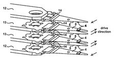
- the number of magnetic disks 2 is three and in which an actuator 5 has six magnetic heads 4 . Since the number of magnetic heads 4 is six, there are two respective intermediate arms 13 between the arms 12 at both ends in each case.
- the drive directions of the piezoelectric elements 14 of the two intermediate arms 13 are specified as being in the opposite direction to that of the arms 12 at both ends.
- the drive directions are shown in FIG. 1 .
- the drive direction of a piezoelectric element 14 can be specified by changing the upper and lower surfaces of the piezoelectric element 14 . Also, the drive direction of the piezoelectric element 14 can be changed over using the preamplifier by providing a control circuit.
- the arm mode is a mode in which balance is achieved by the arms 11 or actuator 5 .
- the arm mode in which the intermediate arms 13 move in anti-phase is a mode in which balance is achieved by the intermediate arms 13 , so little excitation of the both-end arms 12 takes place. The same applies in the case of the arm mode in which the arms 12 at both ends move in anti-phase.
- the phase lag produced by the notch filter can be reduced by reducing the number of excited modes to a single mode, and ensuring that all of the heads of the excited mode are in phase.
- a control system is available apart from gain stabilization control.
- phase loss can be reduced by decreasing the frequency width employed for the notch filter.
- a control system in which phase stabilization is applied to the excited arm mode Regarding the drive system of the piezoelectric elements, the two intermediate arms 13 and the arms 12 at both ends are respectively driven in the same direction, and the piezoelectric elements 14 of the intermediate arms 13 and the arms 12 at both ends are driven in the opposite direction.
- phase stabilization control is that, if the excited modes are in phase, it is possible to achieve control irrespective of the gain of the excited arm mode and, furthermore that vibration produced by errors in positional location at the frequency of the mode in which phase stabilization control is performed can be forcibly suppressed.
- the control bandwidth can be improved by mounting a micro-actuator 8 , so low-band torque noise and/or external disturbance of the low-frequency region, such as disk flutter can be suppressed, but vibration produced by errors in positional location i.e. flutter produced by arm vibration at frequencies above the control band cannot be suppressed.
- FIG. 7 shows a comparison of the sensitivity function obtained with the first embodiment and the sensitivity function of the prior art.
- FIG. 8 shows a comparison of the sensitivity function obtained with the second embodiment and the sensitivity function of the prior art. It can be seen from FIG. 7 that, in one embodiment, as seen in particular in the vicinity of 2300 Hz, by reducing the phase loss, the gain of the sensitivity function is lowered in the lower frequency band, so stable control can be achieved. Also, another embodiment, as seen in the vicinity of 8500 Hz in FIG. 8 , the sensitivity function is no more than 0 dB at the frequency of the arm mode, so it can be seen that arm flutter can be suppressed.
- a six-head actuator 5 is utilized, an actuator 5 having four magnetic heads 4 at the upper and lower surfaces of two magnetic disks 2 is utilized. Also, if the phase of the arm modes of all of the heads is the same, the a six-headed actuator or an actuator having for magnetic heads are utilized even when the adjacent arm modes are more than one.
Abstract
Description
Claims (7)
Applications Claiming Priority (2)
| Application Number | Priority Date | Filing Date | Title |
|---|---|---|---|
| JP2009281627A JP5473126B2 (en) | 2009-12-11 | 2009-12-11 | Magnetic head driving device and magnetic disk device using the same |
| JP2009-281627 | 2009-12-11 |
Publications (2)
| Publication Number | Publication Date |
|---|---|
| US20110141614A1 US20110141614A1 (en) | 2011-06-16 |
| US8699166B2 true US8699166B2 (en) | 2014-04-15 |
Family
ID=44142627
Family Applications (1)
| Application Number | Title | Priority Date | Filing Date |
|---|---|---|---|
| US12/963,111 Active 2032-10-10 US8699166B2 (en) | 2009-12-11 | 2010-12-08 | Magnetic head drive device with micro-actuators of end arms rotating in a direction opposite micro-actuators of intermediate arms |
Country Status (2)
| Country | Link |
|---|---|
| US (1) | US8699166B2 (en) |
| JP (1) | JP5473126B2 (en) |
Cited By (1)
| Publication number | Priority date | Publication date | Assignee | Title |
|---|---|---|---|---|
| CN106887242A (en) * | 2015-12-15 | 2017-06-23 | 株式会社东芝 | Disk device, drive circuit and control method |
Families Citing this family (2)
| Publication number | Priority date | Publication date | Assignee | Title |
|---|---|---|---|---|
| US8699186B1 (en) | 2013-02-22 | 2014-04-15 | Magnecomp Corporation | DSA suspension with mid-load beam mounted dual actuators |
| CN106033675B9 (en) | 2014-12-24 | 2019-04-26 | 株式会社东芝 | Disk set and the control method executed in disk set |
Citations (10)
| Publication number | Priority date | Publication date | Assignee | Title |
|---|---|---|---|---|
| JP2000260140A (en) | 1999-03-09 | 2000-09-22 | Nec Corp | Magnetic head positioning mechanism and its driving system |
| JP2002074872A (en) | 2000-09-05 | 2002-03-15 | Fujitsu Ltd | Head shifter |
| US6542326B1 (en) * | 1999-10-28 | 2003-04-01 | Seagate Technology Llc | Microactuator-induced reactive forces for fine positioning a sensor |
| US6600619B1 (en) * | 1999-02-22 | 2003-07-29 | Seagate Technology Llc | Vibration control of piezoelectric microactuator |
| US6621653B1 (en) * | 2000-06-09 | 2003-09-16 | Hitachi Global Storage Technologies Netherlands B.V. | Secondary actuator system for mode compensation |
| US6624982B2 (en) * | 2000-03-24 | 2003-09-23 | Hitachi, Ltd. | Magnetic disk recording apparatus |
| US6765743B2 (en) * | 2001-04-18 | 2004-07-20 | Hitachi Global Storage Technologies Netherlands. B.V. | Micro-actuator transducer stack inertia cancellation control |
| US6922305B2 (en) * | 2002-11-18 | 2005-07-26 | Hitachi Global Storage Technologies Netherlands B.V. | Apparatus and method for reducing vibrational excitation in storage devices with dual stage actuators |
| US6972924B1 (en) * | 2004-04-02 | 2005-12-06 | Western Digital Technologies, Inc. | Disk drive attenuating excitation of arm vibration mode by simultaneously driving secondary actuator for non-active head |
| US7027253B1 (en) * | 2004-08-06 | 2006-04-11 | Maxtor Corporation | Microactuator servo control during self writing of servo data |
Family Cites Families (1)
| Publication number | Priority date | Publication date | Assignee | Title |
|---|---|---|---|---|
| JP4283979B2 (en) * | 2000-08-21 | 2009-06-24 | 株式会社日立グローバルストレージテクノロジーズ | Positioning control device |
-
2009
- 2009-12-11 JP JP2009281627A patent/JP5473126B2/en active Active
-
2010
- 2010-12-08 US US12/963,111 patent/US8699166B2/en active Active
Patent Citations (11)
| Publication number | Priority date | Publication date | Assignee | Title |
|---|---|---|---|---|
| US6600619B1 (en) * | 1999-02-22 | 2003-07-29 | Seagate Technology Llc | Vibration control of piezoelectric microactuator |
| JP2000260140A (en) | 1999-03-09 | 2000-09-22 | Nec Corp | Magnetic head positioning mechanism and its driving system |
| US6542326B1 (en) * | 1999-10-28 | 2003-04-01 | Seagate Technology Llc | Microactuator-induced reactive forces for fine positioning a sensor |
| US6624982B2 (en) * | 2000-03-24 | 2003-09-23 | Hitachi, Ltd. | Magnetic disk recording apparatus |
| US6621653B1 (en) * | 2000-06-09 | 2003-09-16 | Hitachi Global Storage Technologies Netherlands B.V. | Secondary actuator system for mode compensation |
| JP2002074872A (en) | 2000-09-05 | 2002-03-15 | Fujitsu Ltd | Head shifter |
| US6697211B2 (en) | 2000-09-05 | 2004-02-24 | Fujitsu Limited | Magnetic head drive device |
| US6765743B2 (en) * | 2001-04-18 | 2004-07-20 | Hitachi Global Storage Technologies Netherlands. B.V. | Micro-actuator transducer stack inertia cancellation control |
| US6922305B2 (en) * | 2002-11-18 | 2005-07-26 | Hitachi Global Storage Technologies Netherlands B.V. | Apparatus and method for reducing vibrational excitation in storage devices with dual stage actuators |
| US6972924B1 (en) * | 2004-04-02 | 2005-12-06 | Western Digital Technologies, Inc. | Disk drive attenuating excitation of arm vibration mode by simultaneously driving secondary actuator for non-active head |
| US7027253B1 (en) * | 2004-08-06 | 2006-04-11 | Maxtor Corporation | Microactuator servo control during self writing of servo data |
Cited By (3)
| Publication number | Priority date | Publication date | Assignee | Title |
|---|---|---|---|---|
| CN106887242A (en) * | 2015-12-15 | 2017-06-23 | 株式会社东芝 | Disk device, drive circuit and control method |
| US9824707B2 (en) * | 2015-12-15 | 2017-11-21 | Kabushiki Kaisha Toshiba | Disk apparatus, driver circuit, and control method |
| CN106887242B (en) * | 2015-12-15 | 2019-07-30 | 株式会社东芝 | Disk device, driving circuit and control method |
Also Published As
| Publication number | Publication date |
|---|---|
| JP5473126B2 (en) | 2014-04-16 |
| JP2011123960A (en) | 2011-06-23 |
| US20110141614A1 (en) | 2011-06-16 |
Similar Documents
| Publication | Publication Date | Title |
|---|---|---|
| US9437230B2 (en) | And method of operation of micro-milliactuators and micro-microactuators | |
| US6879466B1 (en) | Disk drive including an actuator with a constrained layer damper disposed upon an actuator body lateral surface | |
| US6816343B1 (en) | Disk drive including an actuator coil with side segments equally overlapping inner and outer magnet sets | |
| US6922305B2 (en) | Apparatus and method for reducing vibrational excitation in storage devices with dual stage actuators | |
| US8797690B2 (en) | Mass balanced flexure gimbal for head gimbal assembly sway mode control | |
| US20180358038A1 (en) | Techniques For Reducing Dynamic Coupling Of System Modes In A Dual Actuator Hard Disk Drive | |
| JP2006190452A (en) | Microactuator, damper, head gimbal assembly, and disk drive using the same | |
| US20050286162A1 (en) | Disk drive device and method of assembling disk drive device | |
| JP2004296074A (en) | Head-gimbal assembly of hard disk drive | |
| US6947260B2 (en) | System and method of damping vibration on coil supports in high performance disk drives with rotary actuators | |
| US7515377B2 (en) | Storage apparatus and control method for detecting vibration produced during seeking | |
| US8699166B2 (en) | Magnetic head drive device with micro-actuators of end arms rotating in a direction opposite micro-actuators of intermediate arms | |
| US6961202B2 (en) | Data storage device having acceleration sensor attached to circuit board for detecting vibrations in planar rotation direction along circuit board | |
| US8305714B2 (en) | Voice-coil motor with voice coils configured oriented in the same direction and substantially overlayed to reduce head vibrations in a disk drive | |
| US20160078890A1 (en) | Head gimbal assembly and storage device provided with the same | |
| US7903377B2 (en) | System, method, and apparatus for an independent flexible cable damper for reducing flexible cable fatigue in a hard disk drive | |
| US7814643B2 (en) | Method for reducing off-track gain for a disk drive actuator | |
| JP2008010063A (en) | Disk drive device and head assembly used therefor | |
| JP4257852B2 (en) | Actuator with improved dynamic characteristics and disk drive having the same | |
| US11348607B1 (en) | Management of actuator dynamics in a multiple actuator hard disk drive with an unequal number of heads on the two outer arms of each actuator | |
| US10593370B1 (en) | Reducing vibration of data storage device in a data storage system | |
| US20080278849A1 (en) | Flow balancer for track misregistration improvement | |
| US9019655B1 (en) | Hard disk drive disk clamp having reduced radial stiffness | |
| US20060007599A1 (en) | System, method, and apparatus for high performance, four-piece suspension with extended hinge plate | |
| JPH11328890A (en) | Head actuator mechanism and magnetic disk device having the same |
Legal Events
| Date | Code | Title | Description |
|---|---|---|---|
| AS | Assignment |
Owner name: HITACHI GLOBAL STORAGE TECHNOLOGIES, NETHERLANDS, Free format text: ASSIGNMENT OF ASSIGNORS INTEREST;ASSIGNORS:SUZUKI, KENJI;NAKAGAWA, SHINSUKE;SHIMIZU, TOSHIHIKO;AND OTHERS;REEL/FRAME:025543/0099 Effective date: 20101124 |
|
| AS | Assignment |
Owner name: HGST NETHERLANDS B.V., NETHERLANDS Free format text: CHANGE OF NAME;ASSIGNOR:HITACHI GLOBAL STORAGE TECHNOLOGIES NETHERLANDS B.V.;REEL/FRAME:029341/0777 Effective date: 20120723 Owner name: HGST, NETHERLANDS B.V., NETHERLANDS Free format text: CHANGE OF NAME;ASSIGNOR:HGST, NETHERLANDS B.V.;REEL/FRAME:029341/0777 Effective date: 20120723 |
|
| FEPP | Fee payment procedure |
Free format text: PAYOR NUMBER ASSIGNED (ORIGINAL EVENT CODE: ASPN); ENTITY STATUS OF PATENT OWNER: LARGE ENTITY |
|
| STCF | Information on status: patent grant |
Free format text: PATENTED CASE |
|
| AS | Assignment |
Owner name: WESTERN DIGITAL TECHNOLOGIES, INC., CALIFORNIA Free format text: ASSIGNMENT OF ASSIGNORS INTEREST;ASSIGNOR:HGST NETHERLANDS B.V.;REEL/FRAME:040826/0327 Effective date: 20160831 |
|
| MAFP | Maintenance fee payment |
Free format text: PAYMENT OF MAINTENANCE FEE, 4TH YEAR, LARGE ENTITY (ORIGINAL EVENT CODE: M1551) Year of fee payment: 4 |
|
| AS | Assignment |
Owner name: JPMORGAN CHASE BANK, N.A., AS AGENT, ILLINOIS Free format text: SECURITY INTEREST;ASSIGNOR:WESTERN DIGITAL TECHNOLOGIES, INC.;REEL/FRAME:052915/0566 Effective date: 20200113 |
|
| MAFP | Maintenance fee payment |
Free format text: PAYMENT OF MAINTENANCE FEE, 8TH YEAR, LARGE ENTITY (ORIGINAL EVENT CODE: M1552); ENTITY STATUS OF PATENT OWNER: LARGE ENTITY Year of fee payment: 8 |
|
| AS | Assignment |
Owner name: WESTERN DIGITAL TECHNOLOGIES, INC., CALIFORNIA Free format text: RELEASE OF SECURITY INTEREST AT REEL 052915 FRAME 0566;ASSIGNOR:JPMORGAN CHASE BANK, N.A.;REEL/FRAME:059127/0001 Effective date: 20220203 |
|
| AS | Assignment |
Owner name: JPMORGAN CHASE BANK, N.A., ILLINOIS Free format text: PATENT COLLATERAL AGREEMENT - A&R LOAN AGREEMENT;ASSIGNOR:WESTERN DIGITAL TECHNOLOGIES, INC.;REEL/FRAME:064715/0001 Effective date: 20230818 |