US8667775B1 - Reverse flow engine core having a ducted fan with integrated secondary flow blades - Google Patents
Reverse flow engine core having a ducted fan with integrated secondary flow blades Download PDFInfo
- Publication number
- US8667775B1 US8667775B1 US12/536,426 US53642609A US8667775B1 US 8667775 B1 US8667775 B1 US 8667775B1 US 53642609 A US53642609 A US 53642609A US 8667775 B1 US8667775 B1 US 8667775B1
- Authority
- US
- United States
- Prior art keywords
- flow
- fan
- gear case
- blades
- blisk
- Prior art date
- Legal status (The legal status is an assumption and is not a legal conclusion. Google has not performed a legal analysis and makes no representation as to the accuracy of the status listed.)
- Active, expires
Links
Images


Classifications
-
- F—MECHANICAL ENGINEERING; LIGHTING; HEATING; WEAPONS; BLASTING
- F01—MACHINES OR ENGINES IN GENERAL; ENGINE PLANTS IN GENERAL; STEAM ENGINES
- F01D—NON-POSITIVE DISPLACEMENT MACHINES OR ENGINES, e.g. STEAM TURBINES
- F01D5/00—Blades; Blade-carrying members; Heating, heat-insulating, cooling or antivibration means on the blades or the members
- F01D5/34—Rotor-blade aggregates of unitary construction, e.g. formed of sheet laminae
-
- F—MECHANICAL ENGINEERING; LIGHTING; HEATING; WEAPONS; BLASTING
- F01—MACHINES OR ENGINES IN GENERAL; ENGINE PLANTS IN GENERAL; STEAM ENGINES
- F01D—NON-POSITIVE DISPLACEMENT MACHINES OR ENGINES, e.g. STEAM TURBINES
- F01D15/00—Adaptations of machines or engines for special use; Combinations of engines with devices driven thereby
- F01D15/12—Combinations with mechanical gearing
-
- F—MECHANICAL ENGINEERING; LIGHTING; HEATING; WEAPONS; BLASTING
- F02—COMBUSTION ENGINES; HOT-GAS OR COMBUSTION-PRODUCT ENGINE PLANTS
- F02C—GAS-TURBINE PLANTS; AIR INTAKES FOR JET-PROPULSION PLANTS; CONTROLLING FUEL SUPPLY IN AIR-BREATHING JET-PROPULSION PLANTS
- F02C3/00—Gas-turbine plants characterised by the use of combustion products as the working fluid
- F02C3/04—Gas-turbine plants characterised by the use of combustion products as the working fluid having a turbine driving a compressor
- F02C3/107—Gas-turbine plants characterised by the use of combustion products as the working fluid having a turbine driving a compressor with two or more rotors connected by power transmission
-
- F—MECHANICAL ENGINEERING; LIGHTING; HEATING; WEAPONS; BLASTING
- F02—COMBUSTION ENGINES; HOT-GAS OR COMBUSTION-PRODUCT ENGINE PLANTS
- F02C—GAS-TURBINE PLANTS; AIR INTAKES FOR JET-PROPULSION PLANTS; CONTROLLING FUEL SUPPLY IN AIR-BREATHING JET-PROPULSION PLANTS
- F02C7/00—Features, components parts, details or accessories, not provided for in, or of interest apart form groups F02C1/00 - F02C6/00; Air intakes for jet-propulsion plants
- F02C7/12—Cooling of plants
- F02C7/16—Cooling of plants characterised by cooling medium
- F02C7/18—Cooling of plants characterised by cooling medium the medium being gaseous, e.g. air
-
- F—MECHANICAL ENGINEERING; LIGHTING; HEATING; WEAPONS; BLASTING
- F02—COMBUSTION ENGINES; HOT-GAS OR COMBUSTION-PRODUCT ENGINE PLANTS
- F02K—JET-PROPULSION PLANTS
- F02K3/00—Plants including a gas turbine driving a compressor or a ducted fan
- F02K3/02—Plants including a gas turbine driving a compressor or a ducted fan in which part of the working fluid by-passes the turbine and combustion chamber
- F02K3/04—Plants including a gas turbine driving a compressor or a ducted fan in which part of the working fluid by-passes the turbine and combustion chamber the plant including ducted fans, i.e. fans with high volume, low pressure outputs, for augmenting the jet thrust, e.g. of double-flow type
- F02K3/062—Plants including a gas turbine driving a compressor or a ducted fan in which part of the working fluid by-passes the turbine and combustion chamber the plant including ducted fans, i.e. fans with high volume, low pressure outputs, for augmenting the jet thrust, e.g. of double-flow type with aft fan
-
- B—PERFORMING OPERATIONS; TRANSPORTING
- B33—ADDITIVE MANUFACTURING TECHNOLOGY
- B33Y—ADDITIVE MANUFACTURING, i.e. MANUFACTURING OF THREE-DIMENSIONAL [3-D] OBJECTS BY ADDITIVE DEPOSITION, ADDITIVE AGGLOMERATION OR ADDITIVE LAYERING, e.g. BY 3-D PRINTING, STEREOLITHOGRAPHY OR SELECTIVE LASER SINTERING
- B33Y80/00—Products made by additive manufacturing
-
- Y—GENERAL TAGGING OF NEW TECHNOLOGICAL DEVELOPMENTS; GENERAL TAGGING OF CROSS-SECTIONAL TECHNOLOGIES SPANNING OVER SEVERAL SECTIONS OF THE IPC; TECHNICAL SUBJECTS COVERED BY FORMER USPC CROSS-REFERENCE ART COLLECTIONS [XRACs] AND DIGESTS
- Y02—TECHNOLOGIES OR APPLICATIONS FOR MITIGATION OR ADAPTATION AGAINST CLIMATE CHANGE
- Y02T—CLIMATE CHANGE MITIGATION TECHNOLOGIES RELATED TO TRANSPORTATION
- Y02T50/00—Aeronautics or air transport
- Y02T50/60—Efficient propulsion technologies, e.g. for aircraft
Definitions
- Embodiments of the disclosure relate generally to the field of ducted fan engines and more particularly to embodiments for integral central blading in the fan for secondary air ducting for cooling of components in a reverse flow turbine engine.
- Ducted fan engines provide high bypass ratios for an efficient propulsion system for air vehicles.
- the fan element provides thrust using air displaced through the nacelle or duct surrounding the fan.
- the motive element for the fan a reciprocating engine or turbojet core is axially aligned with the fan and the fan airflow is directed around the engine or core. Configurations with tractor or pusher style fan/engine integrations may be employed.
- a tractor style engine and fan arrangement may be particularly beneficial where integration of the engine and fan in a blended wing body configuration is desired.
- a turboprop engine provides shaft connection in a tractor arrangement which provides an attractive integrated configuration.
- turboprop engines typically employ a reverse flow arrangement. Use of such reverse flow turbine engines in a ducted fan may result in complex flow arrangements or reduced efficiencies due to the airflow requirements of the engine.
- Exemplary embodiments provide a ducted fan having an engine core driving a fan blisk.
- the fan blisk incorporates a set of thrust fan blades extending from an outer hub and a set of integral secondary flow blades extending intermediate an inner hub and the outer hub.
- a nacelle provides a first flow duct for the thrust fan blades and a secondary flow duct carries flow from the integral secondary flow blades for cooling of components of the engine core.
- an embodiment incorporates reverse flow turbine ducted fan with a reverse flow turbine engine core including a power shaft driven through a gear case and having a fan attachment shaft.
- a fan blisk is attached to the fan attachment shaft and spaced from the gear case by a pressure plate engaging a flange.
- the fan blisk incorporates a set of thrust fan blades extending from an outer hub, a set of integral secondary flow blades extending intermediate an inner hub and the outer hub.
- the flange spans the inner hub with the gear case and flange forming a cooling air plenum.
- a nacelle provides a first flow duct for primary air flow from the thrust fan blades and a plurality of interconnected base gores for stator blades extending to the nacelle provide a structure to support a gear case shroud aligned with the outer hub and carrying secondary air flow from the integral secondary flow blades.
- An air diffuser extends from the gear case shroud and a tail cone having inlets positioned to receive exit flow from the diffuser provides inlet combustion air for the reverse flow turbine engine core.
- a concentric spinner engages the inner and outer hub for secondary air flow.
- a method for fabrication and operation of the exemplary embodiments includes machining thrust blades intermediate an outer hub and a nacelle inner radius in a fan blisk and machining secondary flow blades intermediate an inner hub and the outer hub.
- the fan blisk is then mounted on a fan shaft and a nacelle is provided for flow from the thrust blades.
- a secondary flow path is provided for flow from the secondary flow blades.
- machining the attachment flange in the inner hub is accomplished for relief volumes and weight reduction apertures.
- the method provide for improved operation of a reverse flow turbine engine by providing a fan blisk with primary air flow and secondary air flow.
- Primary flow from the blisk is routed through a nacelle for thrust while secondary flow from the blisk is routed through a plenum.
- Airflow from the plenum may then be employed for cooling components of the reverse flow turbine engine.
- the fan blisk with primary air flow and secondary air flow is formed with thrust flow blades on the blisk between an outer hub and the nacelle secondary flow blades on the blisk between an inner and outer hub.
- cooled component is a gear case
- cooled supporting the plenum as a gear case shroud is accomplished with stators extending from the nacelle.
- a diffuser is also provided for segregating thrust and secondary flow exiting the gear case shroud.
- a tail cone is provided having inlets positioned to receive exit flow from the diffuser to provide inlet combustion air for the reverse flow turbine engine.
- FIG. 1 is an isometric partial section view of an embodiment of a fan blisk integration with a reverse flow turbine engine
- FIG. 2 is a side section view of the embodiment of FIG. 1 with the fan blisk and stator blades eliminated for clarity;
- FIG. 3 is a front view of the fan blisk of the embodiment of FIG. 1 with integral cooling blades;
- FIG. 4 is a side section view of the fan blisk of FIG. 3 along line 4 - 4 ;
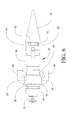
- FIG. 5 is an isometric view of the reverse flow turbine engine showing the gear case and tail cone details
- FIG. 6 is a top view of the reverse flow turbine engine of FIG. 5 ;
- FIG. 6A is a top view of the reverse flow turbine engine with a section view of the fan blisk as shown in FIG. 4 added for clarity of the assembly;
- FIG. 7 is a front pictorial view of the nacelle, stator blades, gear case shroud and gear case cooling fan with the fan blisk eliminated for clarity;
- FIG. 8 is a flow chart of a method of implementing the embodiment disclosed herein.
- FIG. 1 shows an embodiment employing a reverse flow turbine engine core 10 driving a fan blisk 12 .
- Stators 14 extending from base gores 15 provide aerodynamic flow control as well as structural continuity with a nacelle 16 .
- an integral fan shroud 18 is carried by the nacelle 16 providing an inner radius 17 of the nacelle closely matched to the fan thrust blade tip radius for maximized performance.
- the fan shroud may also provide burst protection in the event of blade separation.
- the nacelle which provides ducting of the primary thrust air flow from the fan thrust blades is supported by a pylon 20 which also supports the engine core with a clamp bracket 23 .
- a tail cone 22 with inlets for the engine core is supported from the engine core as will be described in greater detail subsequently.
- Secondary flow from the secondary flow blades in the fan blisk is separated from the primary flow by ducting and is available for usage associated with the engine or alternative secondary air flow requirements.
- Alternative exemplary uses of the secondary flow may be as bleed air for pressurization or pneumatic actuation systems, or lift control such as boundary layer injection.
- stator base gores 15 integrally form or are attached to a gear case shroud 24 , as will be further described with respect to FIG. 7 , as the secondary air flow duct. Shaping of the stator base gores provides appropriate aerodynamics for the thrust flow.
- a flow diffuser 25 extends from the gear case shroud for the purpose of internal aerodynamic efficiency.
- Exhaust ports 26 from an exhaust plenum 28 for the reverse flow engine core with flow elbows removed in FIG. 2 allow visibility of the power shaft 30 from the engine core extending through the exhaust plenum.
- a fan shaft 32 extends from the drive gears in the gear case to engage the fan blisk.
- the configuration of FIG. 2 is particularly adapted to be employed in, but not limited to, a blended wing body application such as the Boeing X-48B.
- Additional applications/uses for turbofans incorporating the embodiments defined herein include: Radio Controlled (hobby) aircraft, Unmanned Aerial Vehicles (UAVs), Remotely Piloted Vehicles (RPV5), Drones and potentially piloted aircraft.
- the fan blisk 12 is shown in detail in FIGS. 3 and 4 .
- a 12.0 inch diameter blisk is employed.
- Multiple thrust blades 40 extend from an outer hub 42 .
- An inner hub 44 supports an attachment flange 46 which spans the inner hub as a web and incorporates a central bore 48 to receive fan shaft 32 .
- Optional weight reduction apertures 50 are provided in the attachment flange.
- Integral secondary flow blades 52 extend between inner hub 44 and outer hub 42 , providing structural continuity for supporting the outer hub and providing a secondary air flow, which for the embodiment shown is employed as cooling airflow for gear case 24 .
- Outer hub 42 has the same exiting inner diameter 54 and outer diameter 56 as the inlet of gear case shroud 24 .
- Airflow generated by the integral secondary flow blades flows from the fan blisk through the gear case shroud and gear case itself, as will be described in greater detail subsequently, and exits through the flow diffuser 25 .
- Use of a prime number of fan blades is employed to minimize harmonic resonance in the fan blisk 12 .
- the fan blisk described for the exemplary embodiment of the drawings uses the prime number thirteen fan blades. Alternate (non prime) blade counts as well as fan diameters ranging from 9.0 inches to 14.0 inches may also be employed to meet the intended thrust requirements or alternative embodiments.
- the reverse flow turbine engine core 10 employs a compressor and turbine section 60 with an annular inlet 62 at the rear of the core for combustion air.
- Expander 64 carries the exhaust gases to the exhaust plenum 28 for outlet through exhaust ports 26 .
- Exhaust elbows 66 direct the exhaust gas flow rearward for thrust recovery.
- Power shaft 30 extends to planetary reduction gearing in gear case 68 to provide power to the fan shaft 32 to drive the fan blisk as previously described.
- a support flange 70 with attachment lugs 72 provides forward structural attachment for the engine core, which in the embodiment shown are attached to the gear case duct.
- a pressure plate 74 is provided for mounting of the fan blisk which spaces the fan blisk mounting flange 46 from the gear case.
- a cooling fan 76 is integrated in the gear case and receives a portion of the secondary air for internal cooling flow as will be described subsequently.
- FIG. 7 shows gear case shroud 34 supported by stator base gores 15 with multiple stator blades 14 extending to the nacelle 16 .
- the embodiment disclosed employs a prime number of stator blades also to minimize harmonic resonances.
- eleven stator blades 14 are employed. Cooling airflow from the integral secondary flow blades in the fan blisk is directed through the gear case shroud cooling the outer wall of the gear case. Additionally, airflow is drawn into the volume aft of the blisk attachment pressure plate 74 which forms a plenum 75 for flow entrainment by fan 76 into the gear case.
- the pressure plate is spaced forward from fan 76 in the gear case front face and in combination with volume cutouts 51 in the blisk flange provides volume for the plenum 75 .
- Flow from the integral secondary flow blades provides pressurization of the plenum assisting flow entrainment by cooling fan 76 .
- alternate stator blade counts and diameters may also be employed to meet the thrust requirements of alternative embodiments.
- Tail cone 22 includes inlets 82 in the upper and lower quadrants of the profile.
- the diffuser minimizes aerodynamic losses of the thrust flow by controlling the flow expansion aft of the stators between the inner geometric profile of the nacelle and outer profile of the diffuser. Aft of the secondary air plenum, the secondary air continues to flow between the outer profile of the engine and inner profile of the diffuser which provides an outer boundary for the secondary flow until the thrust flow is expanded sufficiently for mixing with the secondary flow.
- the thrust and secondary flows are combined to provide a single flow path as the air exits the nacelle. A portion of the combined flow is ingested into the engine as inlet flow for combustion air through inlets 82 to the engine core inlet 62 .
- Tail cone 22 is closed or flattened in the lateral quadrants 84 of the tail cone forward profile to reduce ingestion of hot exhaust gas from the horizontally oriented exhaust elbows 66 .
- a dual concentric spinner having inner cap 90 and an outer toroidal cap 92 is attached to the inner and outer hubs 44 , 42 of the fan blisk using attachment stubs 94 , 96 each having a bore 98 (as seen in FIGS. 3 and 4 ) to receive a securing fastener. Secondary airflow is drawn through the dual concentric spinner for flow entrainment by the integral secondary flow blades. Inner spinner cap 90 may contribute to the plenum volume for the gear case cooling air with flow through weight reduction apertures 50 as best seen in FIG. 4 .
- a method for providing secondary airflow for a reverse flow turbine engine and exemplary use of the secondary flow for the embodiment disclosed herein is outlined in FIG. 8 .
- a fan blisk is formed by machining nylon thrust blades intermediate an outer hub and a nacelle inner radius, step 802 . Additional materials such as aluminum and manufacturing processes such as molding, diffusion bonding, super plastic forming, autoclaving, selective laser sintering (SLS) or other rapid prototyping technologies may be employed to manufacture the blisk to its outer mold line specifications.
- Secondary flow blades are formed intermediate an inner hub and the outer hub, step 804 . The secondary flow blades may be formed using alternative processes as previously described for the thrust blades.
- the attachment flange engaging the inner hub may be additionally machined or otherwise formed for relief volumes and weight reduction apertures, step 806 .
- the fan blisk is mounted on a fan shaft and spaced from an engine core by a pressure plate to form a plenum, step 808 .
- a concentric spinner with inner cap and outer toroidal cap is mounted to the inner and outer hubs respectively, step 810 , to accelerate flow as it enters the secondary flow blades.
- a secondary flow path, in the embodiment shown, a gear case shroud, is provided for direction of secondary flow, step 812 .
- the secondary flow is directed by the gear case shroud around a gear case for cooling and airflow received into the plenum is directed into the gear case by a cooling fan, step 814 .
- a diffuser is provided for directing secondary flow exiting the gear case shroud, step 816 , and mixing with thrust flow exiting the nacelle, step 818 .
- a tail cone is provided having inlets positioned to receive exit flow from the diffuser, step 820 , to provide inlet combustion air for the reverse flow turbine engine, step 822 .
Abstract
Description
Claims (14)
Priority Applications (1)
| Application Number | Priority Date | Filing Date | Title |
|---|---|---|---|
| US12/536,426 US8667775B1 (en) | 2009-08-05 | 2009-08-05 | Reverse flow engine core having a ducted fan with integrated secondary flow blades |
Applications Claiming Priority (1)
| Application Number | Priority Date | Filing Date | Title |
|---|---|---|---|
| US12/536,426 US8667775B1 (en) | 2009-08-05 | 2009-08-05 | Reverse flow engine core having a ducted fan with integrated secondary flow blades |
Publications (1)
| Publication Number | Publication Date |
|---|---|
| US8667775B1 true US8667775B1 (en) | 2014-03-11 |
Family
ID=50192652
Family Applications (1)
| Application Number | Title | Priority Date | Filing Date |
|---|---|---|---|
| US12/536,426 Active 2033-09-22 US8667775B1 (en) | 2009-08-05 | 2009-08-05 | Reverse flow engine core having a ducted fan with integrated secondary flow blades |
Country Status (1)
| Country | Link |
|---|---|
| US (1) | US8667775B1 (en) |
Cited By (24)
| Publication number | Priority date | Publication date | Assignee | Title |
|---|---|---|---|---|
| US20130008144A1 (en) * | 2011-07-05 | 2013-01-10 | Gallagher Edward J | Efficient, low pressure ratio propulsor for gas turbine engines |
| US20130014488A1 (en) * | 2011-07-05 | 2013-01-17 | Gallagher Edward J | Efficient, low pressure ratio propulsor for gas turbine engines |
| US9470093B2 (en) | 2015-03-18 | 2016-10-18 | United Technologies Corporation | Turbofan arrangement with blade channel variations |
| WO2018009420A1 (en) * | 2016-07-06 | 2018-01-11 | General Electric Company | Turbine engine and method of assembling |
| US9909505B2 (en) | 2011-07-05 | 2018-03-06 | United Technologies Corporation | Efficient, low pressure ratio propulsor for gas turbine engines |
| US9914170B2 (en) | 2014-06-13 | 2018-03-13 | Hamilton Sundstrand Corporation | Method for making an integrally bladed rotor with hollow blades |
| US20180370647A1 (en) * | 2017-06-21 | 2018-12-27 | General Electric Company Polska SP z o.o. | Exhaust stub for an aircraft engine assembly |
| US10294821B2 (en) | 2017-04-12 | 2019-05-21 | General Electric Company | Interturbine frame for gas turbine engine |
| US10336449B2 (en) * | 2015-04-20 | 2019-07-02 | Sikorsky Aircraft Corporation | Engine installation of vertical take-off and landing (VTOL) aircraft |
| US10393019B2 (en) | 2016-07-28 | 2019-08-27 | Pratt & Whitney Canada Corp. | Assembly and method for influencing flow through a fan of a gas turbine engine |
| US10539020B2 (en) | 2017-01-23 | 2020-01-21 | General Electric Company | Two spool gas turbine engine with interdigitated turbine section |
| US10544793B2 (en) | 2017-01-25 | 2020-01-28 | General Electric Company | Thermal isolation structure for rotating turbine frame |
| US10544734B2 (en) | 2017-01-23 | 2020-01-28 | General Electric Company | Three spool gas turbine engine with interdigitated turbine section |
| US10605168B2 (en) | 2017-05-25 | 2020-03-31 | General Electric Company | Interdigitated turbine engine air bearing cooling structure and method of thermal management |
| US10655537B2 (en) | 2017-01-23 | 2020-05-19 | General Electric Company | Interdigitated counter rotating turbine system and method of operation |
| US10669893B2 (en) | 2017-05-25 | 2020-06-02 | General Electric Company | Air bearing and thermal management nozzle arrangement for interdigitated turbine engine |
| US10718265B2 (en) | 2017-05-25 | 2020-07-21 | General Electric Company | Interdigitated turbine engine air bearing and method of operation |
| US10787931B2 (en) | 2017-05-25 | 2020-09-29 | General Electric Company | Method and structure of interdigitated turbine engine thermal management |
| US10876407B2 (en) | 2017-02-16 | 2020-12-29 | General Electric Company | Thermal structure for outer diameter mounted turbine blades |
| CN112189079A (en) * | 2018-05-24 | 2021-01-05 | 赛峰飞机发动机公司 | Fabric comprising aramid fibers for protecting blades from impacts |
| GB2587668A (en) * | 2019-10-02 | 2021-04-07 | Advanced Mobility Res And Development Ltd | Systems and methods for aircraft |
| US11060406B2 (en) | 2019-10-11 | 2021-07-13 | Pratt & Whitney Canada Corp. | Rotor for gas turbine engine |
| US11428160B2 (en) | 2020-12-31 | 2022-08-30 | General Electric Company | Gas turbine engine with interdigitated turbine and gear assembly |
| US11814152B2 (en) | 2020-07-20 | 2023-11-14 | The Boeing Company | Methods and apparatus for accelerating an aircraft fuselage boundary layer via a fan powered by an auxiliary power unit of the aircraft |
Citations (38)
| Publication number | Priority date | Publication date | Assignee | Title |
|---|---|---|---|---|
| US1414418A (en) * | 1920-06-28 | 1922-05-02 | Zeppelin Luftschiffbau | Cooling device for aerial vehicles |
| US1611658A (en) * | 1925-07-22 | 1926-12-21 | Magni Pietro | Driving apparatus for high-speed locomotive craft |
| US1927921A (en) * | 1931-07-25 | 1933-09-26 | Francis T Courtney | Spinner for aircraft propellers |
| US2330622A (en) * | 1939-04-01 | 1943-09-28 | Ramshorn Reinhard | Guiding and controlling device for cowlings |
| US2407223A (en) * | 1945-01-09 | 1946-09-10 | United Aircraft Corp | Engine cooling and charging apparatus |
| US2504181A (en) * | 1950-04-18 | Double compound independent rotor | ||
| US2546420A (en) * | 1944-03-28 | 1951-03-27 | Power Jets Res & Dev Ltd | Internal-combustion turbine power plant |
| US2622688A (en) * | 1949-12-06 | 1952-12-23 | United Aircraft Corp | Spinner construction with boundary layer control |
| US2704434A (en) * | 1950-03-20 | 1955-03-22 | Heinz E Schmitt | High pressure ratio gas turbine of the dual set type |
| US2726725A (en) * | 1952-04-07 | 1955-12-13 | Mark R Nichols | Propeller spinner utilizing boundary control by blowing |
| US3131536A (en) * | 1961-06-30 | 1964-05-05 | Bristol Siddeley Engines Ltd | Jet propulsion power plants of the combustion turbine type |
| US3253406A (en) * | 1966-05-31 | Turbine propulsion unit | ||
| US3494539A (en) * | 1967-04-03 | 1970-02-10 | Rolls Royce | Fluid flow machine |
| US3549272A (en) * | 1967-12-12 | 1970-12-22 | Snecma | Improvements in or relating to blading arrangement for turbomachines |
| US3589132A (en) * | 1969-06-04 | 1971-06-29 | Garrett Corp | Gas turbine engine |
| US3703081A (en) * | 1970-11-20 | 1972-11-21 | Gen Electric | Gas turbine engine |
| US3779486A (en) * | 1970-09-26 | 1973-12-18 | Great Britain & Northern Irela | Gas turbine engines |
| US3859785A (en) * | 1973-12-17 | 1975-01-14 | Curtiss Wright Corp | Turbine engine with integral compressor and alternator rotor |
| US3867813A (en) * | 1971-10-05 | 1975-02-25 | Mtu Muenchen Gmbh | Turbojet engine for vertical or short take-off and landing airplanes |
| US3903690A (en) * | 1973-02-12 | 1975-09-09 | Gen Electric | Turbofan engine lubrication means |
| US3916620A (en) * | 1974-05-16 | 1975-11-04 | Hawker Siddeley Dynamics Ltd | Propulsive ducted fans |
| US4005575A (en) * | 1974-09-11 | 1977-02-01 | Rolls-Royce (1971) Limited | Differentially geared reversible fan for ducted fan gas turbine engines |
| US4037409A (en) * | 1975-03-06 | 1977-07-26 | Motoren- Und Turbinen-Union Munchen Gmbh | Gas turbine engine for vehicles |
| US4380897A (en) * | 1979-11-14 | 1983-04-26 | Bbc Brown, Boveri & Company Limited | Gas turbine containing an additional combustion gas compressor |
| US4765135A (en) * | 1986-10-29 | 1988-08-23 | Societe Nationale D'etude Et De Construction De Moteurs D'aviation "S.N.E.C.M.A." | Gas turbine engine |
| US5103635A (en) * | 1989-09-27 | 1992-04-14 | Societe Nationale D'etude Et De Construction De Moteurs D'aviation "S.N.E.C.M.A." | Contra-rotating fan engine |
| US5105618A (en) * | 1989-04-26 | 1992-04-21 | Societe Nationale D'etude Et De Construction De Moteurs D'aviation "S.N.E.C.M.A." | Counterrotating fan engine |
| US5562419A (en) * | 1995-06-06 | 1996-10-08 | General Electric Company | Shrouded fan blisk |
| US5816042A (en) * | 1996-12-27 | 1998-10-06 | United Technologies Corporation | Flow diverter system for multiple streams for gas turbine engines |
| US6217283B1 (en) * | 1999-04-20 | 2001-04-17 | General Electric Company | Composite fan platform |
| US6494032B2 (en) * | 2000-03-11 | 2002-12-17 | Rolls-Royce Plc | Ducted fan gas turbine engine with frangible connection |
| US6751946B2 (en) * | 2002-01-18 | 2004-06-22 | Kamdax Development Ltd. | Ducted fan integrated power plant unit having propeller with central blade wheel |
| US6868664B2 (en) * | 2000-12-22 | 2005-03-22 | United Technologies Corporation | Main propulsion engine system integrated with secondary power unit |
| US20060102780A1 (en) * | 2004-09-17 | 2006-05-18 | Robert Parks | Ducted spinner for engine cooling |
| US7322180B2 (en) * | 2004-02-06 | 2008-01-29 | Snecma Moteurs | Turbo-jet engine with fan integral with a drive shaft supported by first and second bearings |
| US20080095628A1 (en) * | 2004-12-01 | 2008-04-24 | United Technologies Corporation | Close Coupled Gearbox Assembly For A Tip Turbine Engine |
| US7475549B2 (en) * | 2005-08-03 | 2009-01-13 | Hamilton Sundstrand Corporation | Thermal management system for a gas turbine engine |
| US7490460B2 (en) * | 2005-10-19 | 2009-02-17 | General Electric Company | Gas turbine engine assembly and methods of assembling same |
-
2009
- 2009-08-05 US US12/536,426 patent/US8667775B1/en active Active
Patent Citations (39)
| Publication number | Priority date | Publication date | Assignee | Title |
|---|---|---|---|---|
| US3253406A (en) * | 1966-05-31 | Turbine propulsion unit | ||
| US2504181A (en) * | 1950-04-18 | Double compound independent rotor | ||
| US1414418A (en) * | 1920-06-28 | 1922-05-02 | Zeppelin Luftschiffbau | Cooling device for aerial vehicles |
| US1611658A (en) * | 1925-07-22 | 1926-12-21 | Magni Pietro | Driving apparatus for high-speed locomotive craft |
| US1927921A (en) * | 1931-07-25 | 1933-09-26 | Francis T Courtney | Spinner for aircraft propellers |
| US2330622A (en) * | 1939-04-01 | 1943-09-28 | Ramshorn Reinhard | Guiding and controlling device for cowlings |
| US2546420A (en) * | 1944-03-28 | 1951-03-27 | Power Jets Res & Dev Ltd | Internal-combustion turbine power plant |
| US2407223A (en) * | 1945-01-09 | 1946-09-10 | United Aircraft Corp | Engine cooling and charging apparatus |
| US2622688A (en) * | 1949-12-06 | 1952-12-23 | United Aircraft Corp | Spinner construction with boundary layer control |
| US2704434A (en) * | 1950-03-20 | 1955-03-22 | Heinz E Schmitt | High pressure ratio gas turbine of the dual set type |
| US2726725A (en) * | 1952-04-07 | 1955-12-13 | Mark R Nichols | Propeller spinner utilizing boundary control by blowing |
| US3131536A (en) * | 1961-06-30 | 1964-05-05 | Bristol Siddeley Engines Ltd | Jet propulsion power plants of the combustion turbine type |
| US3494539A (en) * | 1967-04-03 | 1970-02-10 | Rolls Royce | Fluid flow machine |
| US3549272A (en) * | 1967-12-12 | 1970-12-22 | Snecma | Improvements in or relating to blading arrangement for turbomachines |
| US3589132A (en) * | 1969-06-04 | 1971-06-29 | Garrett Corp | Gas turbine engine |
| US3779486A (en) * | 1970-09-26 | 1973-12-18 | Great Britain & Northern Irela | Gas turbine engines |
| US3703081A (en) * | 1970-11-20 | 1972-11-21 | Gen Electric | Gas turbine engine |
| US3867813A (en) * | 1971-10-05 | 1975-02-25 | Mtu Muenchen Gmbh | Turbojet engine for vertical or short take-off and landing airplanes |
| US3903690A (en) * | 1973-02-12 | 1975-09-09 | Gen Electric | Turbofan engine lubrication means |
| US3859785A (en) * | 1973-12-17 | 1975-01-14 | Curtiss Wright Corp | Turbine engine with integral compressor and alternator rotor |
| US3916620A (en) * | 1974-05-16 | 1975-11-04 | Hawker Siddeley Dynamics Ltd | Propulsive ducted fans |
| US4005575A (en) * | 1974-09-11 | 1977-02-01 | Rolls-Royce (1971) Limited | Differentially geared reversible fan for ducted fan gas turbine engines |
| US4037409A (en) * | 1975-03-06 | 1977-07-26 | Motoren- Und Turbinen-Union Munchen Gmbh | Gas turbine engine for vehicles |
| US4380897A (en) * | 1979-11-14 | 1983-04-26 | Bbc Brown, Boveri & Company Limited | Gas turbine containing an additional combustion gas compressor |
| US4765135A (en) * | 1986-10-29 | 1988-08-23 | Societe Nationale D'etude Et De Construction De Moteurs D'aviation "S.N.E.C.M.A." | Gas turbine engine |
| US5105618A (en) * | 1989-04-26 | 1992-04-21 | Societe Nationale D'etude Et De Construction De Moteurs D'aviation "S.N.E.C.M.A." | Counterrotating fan engine |
| US5103635A (en) * | 1989-09-27 | 1992-04-14 | Societe Nationale D'etude Et De Construction De Moteurs D'aviation "S.N.E.C.M.A." | Contra-rotating fan engine |
| US5562419A (en) * | 1995-06-06 | 1996-10-08 | General Electric Company | Shrouded fan blisk |
| US5816042A (en) * | 1996-12-27 | 1998-10-06 | United Technologies Corporation | Flow diverter system for multiple streams for gas turbine engines |
| US6102329A (en) * | 1996-12-27 | 2000-08-15 | United Technologies Corporation | Flow diverter system for multiple streams for gas turbine engine |
| US6217283B1 (en) * | 1999-04-20 | 2001-04-17 | General Electric Company | Composite fan platform |
| US6494032B2 (en) * | 2000-03-11 | 2002-12-17 | Rolls-Royce Plc | Ducted fan gas turbine engine with frangible connection |
| US6868664B2 (en) * | 2000-12-22 | 2005-03-22 | United Technologies Corporation | Main propulsion engine system integrated with secondary power unit |
| US6751946B2 (en) * | 2002-01-18 | 2004-06-22 | Kamdax Development Ltd. | Ducted fan integrated power plant unit having propeller with central blade wheel |
| US7322180B2 (en) * | 2004-02-06 | 2008-01-29 | Snecma Moteurs | Turbo-jet engine with fan integral with a drive shaft supported by first and second bearings |
| US20060102780A1 (en) * | 2004-09-17 | 2006-05-18 | Robert Parks | Ducted spinner for engine cooling |
| US20080095628A1 (en) * | 2004-12-01 | 2008-04-24 | United Technologies Corporation | Close Coupled Gearbox Assembly For A Tip Turbine Engine |
| US7475549B2 (en) * | 2005-08-03 | 2009-01-13 | Hamilton Sundstrand Corporation | Thermal management system for a gas turbine engine |
| US7490460B2 (en) * | 2005-10-19 | 2009-02-17 | General Electric Company | Gas turbine engine assembly and methods of assembling same |
Cited By (39)
| Publication number | Priority date | Publication date | Assignee | Title |
|---|---|---|---|---|
| US10288009B2 (en) | 2011-07-05 | 2019-05-14 | United Technologies Corporation | Efficient, low pressure ratio propulsor for gas turbine engines |
| US20130014488A1 (en) * | 2011-07-05 | 2013-01-17 | Gallagher Edward J | Efficient, low pressure ratio propulsor for gas turbine engines |
| US9121368B2 (en) * | 2011-07-05 | 2015-09-01 | United Technologies Corporation | Efficient, low pressure ratio propulsor for gas turbine engines |
| US9121412B2 (en) * | 2011-07-05 | 2015-09-01 | United Technologies Corporation | Efficient, low pressure ratio propulsor for gas turbine engines |
| US10605202B2 (en) | 2011-07-05 | 2020-03-31 | United Technologies Corporation | Efficient, low pressure ratio propulsor for gas turbine engines |
| US11073157B2 (en) | 2011-07-05 | 2021-07-27 | Raytheon Technologies Corporation | Efficient, low pressure ratio propulsor for gas turbine engines |
| US9909505B2 (en) | 2011-07-05 | 2018-03-06 | United Technologies Corporation | Efficient, low pressure ratio propulsor for gas turbine engines |
| US9926885B2 (en) | 2011-07-05 | 2018-03-27 | United Technologies Corporation | Efficient, low pressure ratio propulsor for gas turbine engines |
| US10012150B2 (en) | 2011-07-05 | 2018-07-03 | United Technologies Corporation | Efficient, low pressure ratio propulsor for gas turbine engines |
| US20130008144A1 (en) * | 2011-07-05 | 2013-01-10 | Gallagher Edward J | Efficient, low pressure ratio propulsor for gas turbine engines |
| US10233868B2 (en) | 2011-07-05 | 2019-03-19 | United Technologies Corporation | Efficient, low pressure ratio propulsor for gas turbine engines |
| US9914170B2 (en) | 2014-06-13 | 2018-03-13 | Hamilton Sundstrand Corporation | Method for making an integrally bladed rotor with hollow blades |
| US10358924B2 (en) | 2015-03-18 | 2019-07-23 | United Technologies Corporation | Turbofan arrangement with blade channel variations |
| US11118459B2 (en) | 2015-03-18 | 2021-09-14 | Aytheon Technologies Corporation | Turbofan arrangement with blade channel variations |
| US11466572B2 (en) | 2015-03-18 | 2022-10-11 | Raytheon Technologies Corporation | Gas turbine engine with blade channel variations |
| US9470093B2 (en) | 2015-03-18 | 2016-10-18 | United Technologies Corporation | Turbofan arrangement with blade channel variations |
| US10336449B2 (en) * | 2015-04-20 | 2019-07-02 | Sikorsky Aircraft Corporation | Engine installation of vertical take-off and landing (VTOL) aircraft |
| US10563516B2 (en) | 2016-07-06 | 2020-02-18 | General Electric Company | Turbine engine and method of assembling |
| WO2018009420A1 (en) * | 2016-07-06 | 2018-01-11 | General Electric Company | Turbine engine and method of assembling |
| US10393019B2 (en) | 2016-07-28 | 2019-08-27 | Pratt & Whitney Canada Corp. | Assembly and method for influencing flow through a fan of a gas turbine engine |
| US10655537B2 (en) | 2017-01-23 | 2020-05-19 | General Electric Company | Interdigitated counter rotating turbine system and method of operation |
| US10539020B2 (en) | 2017-01-23 | 2020-01-21 | General Electric Company | Two spool gas turbine engine with interdigitated turbine section |
| US10544734B2 (en) | 2017-01-23 | 2020-01-28 | General Electric Company | Three spool gas turbine engine with interdigitated turbine section |
| US10544793B2 (en) | 2017-01-25 | 2020-01-28 | General Electric Company | Thermal isolation structure for rotating turbine frame |
| US10876407B2 (en) | 2017-02-16 | 2020-12-29 | General Electric Company | Thermal structure for outer diameter mounted turbine blades |
| US10294821B2 (en) | 2017-04-12 | 2019-05-21 | General Electric Company | Interturbine frame for gas turbine engine |
| US10605168B2 (en) | 2017-05-25 | 2020-03-31 | General Electric Company | Interdigitated turbine engine air bearing cooling structure and method of thermal management |
| US10787931B2 (en) | 2017-05-25 | 2020-09-29 | General Electric Company | Method and structure of interdigitated turbine engine thermal management |
| US10669893B2 (en) | 2017-05-25 | 2020-06-02 | General Electric Company | Air bearing and thermal management nozzle arrangement for interdigitated turbine engine |
| US10718265B2 (en) | 2017-05-25 | 2020-07-21 | General Electric Company | Interdigitated turbine engine air bearing and method of operation |
| US20180370647A1 (en) * | 2017-06-21 | 2018-12-27 | General Electric Company Polska SP z o.o. | Exhaust stub for an aircraft engine assembly |
| CN112189079A (en) * | 2018-05-24 | 2021-01-05 | 赛峰飞机发动机公司 | Fabric comprising aramid fibers for protecting blades from impacts |
| CN112189079B (en) * | 2018-05-24 | 2022-12-23 | 赛峰飞机发动机公司 | Fabric comprising aramid fibers for protecting blades from impacts |
| GB2587668A (en) * | 2019-10-02 | 2021-04-07 | Advanced Mobility Res And Development Ltd | Systems and methods for aircraft |
| WO2021064376A3 (en) * | 2019-10-02 | 2021-06-24 | Electric Aviation Group Ltd | Systems and methods for aircraft |
| WO2021064380A3 (en) * | 2019-10-02 | 2021-06-24 | Electric Aviation Group Ltd | Systems and methods for aircraft |
| US11060406B2 (en) | 2019-10-11 | 2021-07-13 | Pratt & Whitney Canada Corp. | Rotor for gas turbine engine |
| US11814152B2 (en) | 2020-07-20 | 2023-11-14 | The Boeing Company | Methods and apparatus for accelerating an aircraft fuselage boundary layer via a fan powered by an auxiliary power unit of the aircraft |
| US11428160B2 (en) | 2020-12-31 | 2022-08-30 | General Electric Company | Gas turbine engine with interdigitated turbine and gear assembly |
Similar Documents
| Publication | Publication Date | Title |
|---|---|---|
| US8667775B1 (en) | Reverse flow engine core having a ducted fan with integrated secondary flow blades | |
| US8667774B2 (en) | Coannular ducted fan | |
| US8826641B2 (en) | Thermal management system integrated pylon | |
| EP2578843B1 (en) | Combined Pump system for size reduction of thermal management heat exchangers and optimized ventilation to the aircraft cabin | |
| EP3284942B1 (en) | Direct drive aft fan engine | |
| US10920713B2 (en) | Compression cowl for jet engine exhaust | |
| US20110171007A1 (en) | Convertible fan system | |
| US20110167792A1 (en) | Adaptive engine | |
| EP2085600B1 (en) | Thermal management system integrated pylon | |
| US11661894B2 (en) | Geared turbine engine with relatively lightweight propulsor module | |
| EP2971729B1 (en) | Gas turbine engine and ventilation system | |
| US11655767B2 (en) | Gearbox for an engine | |
| US20220282925A1 (en) | Multi-fluid heat exchanger | |
| US11834961B2 (en) | Coolant transfer system and method for a dual-wall airfoil | |
| EP4209672A1 (en) | Three-stream gas turbine engine control | |
| CN114991963A (en) | Three-flow engine with heat exchanger | |
| EP3628589B1 (en) | Active laminar flow control structural plenums fastened | |
| US20170057649A1 (en) | Integrated aircraft propulsion system | |
| Kisska et al. | Reverse flow engine core having a ducted fan with integrated secondary flow blades | |
| US11674438B1 (en) | Thermal management system | |
| US20230358170A1 (en) | Diffuser with passlets | |
| CN117823282A (en) | Thermal management system |
Legal Events
| Date | Code | Title | Description |
|---|---|---|---|
| AS | Assignment |
Owner name: AIR FORCE, UNITED STATES OF AMERICA AS REPRESENTED Free format text: CONFIRMATORY LICENSE;ASSIGNOR:BOEING COMPANY, THE;REEL/FRAME:023953/0782 Effective date: 20091112 |
|
| STCF | Information on status: patent grant |
Free format text: PATENTED CASE |
|
| MAFP | Maintenance fee payment |
Free format text: PAYMENT OF MAINTENANCE FEE, 4TH YEAR, LARGE ENTITY (ORIGINAL EVENT CODE: M1551) Year of fee payment: 4 |
|
| MAFP | Maintenance fee payment |
Free format text: PAYMENT OF MAINTENANCE FEE, 8TH YEAR, LARGE ENTITY (ORIGINAL EVENT CODE: M1552); ENTITY STATUS OF PATENT OWNER: LARGE ENTITY Year of fee payment: 8 |